J74927A-A-RT-00006 B5-Brynhild Comparative Assessment Report
61
Confidential – Do not disclose without authorisation © Copyright Genesis Oil and Gas Consultants, Ltd. Printed copy is uncontrolled Report Comparative Assessment (CA) Report Prepared for: Lundin Norway AS Client Doc. No.: 21488-TEFMC-000-Z-RA-00002 Prepared by: Genesis Pavilion 3, Aspect 32, Prospect Road, Arnhall Business Park, Westhill, AB32 6FE, UK Tel: +44 (0)1224 615100 Fax: +44 (0)1224 615111 www.genesisoilandgas.com Project Title: Brynhild Decommissioning Project Document No: J74927A-A-RT-00006 Date: Jan, 2020 Rev No. Date Description Issued by Checked by Approved by Client Approval Orig. Client B1 A 28/03/19 Issued for client review JW MMcF AH B2 B 10/05/19 Updated and re-issued for OPRED review J Wilson A Hossain A Hossain T Wideroe B3 C 26/07/19 Updated incorporating OPRED comments received 10July19 and re-issued for Client Review J Wilson A Hossain A Hossain B4 D 23/08/19 Issued for OPRED 2 nd review J Wilson A Hossain A Hossain T Wideroe B5 01 07/01/20 Issued for Consultation (Final) J Wilson A Hossain A Hossain L Hanken
Transcript of J74927A-A-RT-00006 B5-Brynhild Comparative Assessment Report

Confidential – Do not disclose without authorisation © Copyright Genesis Oil and Gas Consultants, Ltd. Printed copy is uncontrolled
Report
Comparative Assessment (CA) Report
Prepared for: Lundin Norway AS Client Doc. No.: 21488-TEFMC-000-Z-RA-00002
Prepared by: Genesis Pavilion 3, Aspect 32, Prospect Road, Arnhall Business Park, Westhill, AB32 6FE, UK
Tel: +44 (0)1224 615100
Fax: +44 (0)1224 615111
www.genesisoilandgas.com
Project Title: Brynhild Decommissioning Project Document No: J74927A-A-RT-00006 Date: Jan, 2020
Rev No. Date Description Issued by
Checked by
Approved by
Client Approval Orig. Client
B1 A 28/03/19 Issued for client review JW MMcF AH
B2 B 10/05/19 Updated and re-issued for OPRED review
J Wilson A Hossain A Hossain T Wideroe
B3 C 26/07/19 Updated incorporating OPRED comments received 10July19 and re-issued for Client Review
J Wilson A Hossain A Hossain
B4 D 23/08/19 Issued for OPRED 2nd review J Wilson A Hossain A Hossain T Wideroe
B5 01 07/01/20 Issued for Consultation (Final) J Wilson A Hossain A Hossain L Hanken

Project Title: Brynhild Decommissioning Project - Comparative Assessment Report
Document & Rev No: J74927A-A-RT-00006/B6
Date: Jan, 2020
Confidential – Do not disclose without authorisation © Copyright Genesis Oil and Gas Consultants, Ltd. Printed copy is uncontrolled Page 2 of 61
Contents
ABBREVIATIONS ................................................................................................................... 5
HOLDS LIST ........................................................................................................................... 7
REVISION HISTORY .............................................................................................................. 8
1.0 EXECUTIVE SUMMARY ................................................................................................ 9
2.0 PROJECT OVERVIEW ................................................................................................ 11
2.1 Field Description .................................................................................................. 11
2.2 Field History and Current Status .......................................................................... 16
2.3 Regulatory Responsibility .................................................................................... 17
2.4 Environmental and Social Overview .................................................................... 17 2.4.1 Metocean Conditions .................................................................................. 17
2.4.2 Sediments ................................................................................................... 17
2.4.3 Biological Environment ............................................................................... 18
2.4.4 Conservation Designations ......................................................................... 18
2.4.5 Socio Economic Environment ..................................................................... 18
2.5 Inclusions, Exclusions and Boundaries for CA .................................................... 19 2.5.1 Inclusions .................................................................................................... 19
2.5.2 Exclusions ................................................................................................... 20
2.5.3 Boundaries .................................................................................................. 21
3.0 EVALUATION WORKSHOP CONSIDERATIONS ....................................................... 25
3.1 Decommissioning options considered ................................................................. 25 4.0 OVERVIEW OF THE CA PROCESS............................................................................ 34
4.1.1 Overview ..................................................................................................... 34
4.1.2 OPRED Guide to Comparative Assessment ............................................... 34
4.2 Industry Guidelines .............................................................................................. 35 4.2.1 The CA Process .......................................................................................... 35
4.2.2 Evaluation Method ...................................................................................... 36
4.2.3 Pipeline Grouping ....................................................................................... 37
4.3 Evaluation Workshop Details ............................................................................... 37
4.4 Evaluation Workshop Tools ................................................................................. 37 4.4.1 Qualitative Assessment - Rating Guide Table ............................................ 37
4.4.2 Decommissioning Fact Sheets ................................................................... 37
4.4.3 Evaluation / Rating Workbook ..................................................................... 38
4.5 Mechanics of Rating the Options ......................................................................... 38 5.0 COMPARATIVE ASSESSMENT EVALUATION RESULTS......................................... 39

Project Title: Brynhild Decommissioning Project - Comparative Assessment Report
Document & Rev No: J74927A-A-RT-00006/B6
Date: Jan, 2020
Confidential – Do not disclose without authorisation © Copyright Genesis Oil and Gas Consultants, Ltd. Printed copy is uncontrolled Page 3 of 61
5.1 Conclusions and Recommendations ................................................................... 39
5.2 Key influencing factors in ranking of the options: ................................................ 39 5.2.1 Option 2c): Remediate in-situ - Exposed sections cut and removed .......... 39
5.2.2 Option 2b): Remediate in-situ - Exposed sections trenched and buried ..... 40
5.2.3 Option 2a): Remediate in-situ - Exposed sections rock covered ................ 40
5.2.4 Option 3): Decommission in-situ (Do nothing) ............................................ 40
5.2.5 Option 1a): Total Removal – by Reverse Reeling ....................................... 41
6.0 REFERENCES ............................................................................................................. 42
APPENDIX A: CA WORKSHOP DETAILS............................................................................ 43
Date, Time and Venue .................................................................................................. 43
Participants ................................................................................................................... 43 APPENDIX B: EVALUATION RATING GUIDE TABLE ......................................................... 44
APPENDIX C: WORKSHOP FACT SHEETS – BY CRITERIA ............................................. 45
Technical Fact Sheets .................................................................................................. 45
Environmental Fact Sheets .......................................................................................... 45
Safety Fact Sheets ....................................................................................................... 46 APPENDIX D: EVALUATION RESULTS TABLES - SUMMARIES ....................................... 47
Visual Rating Results ................................................................................................... 47
Overall Narrative Summary .......................................................................................... 48 APPENDIX E: EVALUATION RESULTS TABLES – DETAILED BY CRITERIA ................... 49
Technical & Safety Criteria ........................................................................................... 49
Social and Economic Criteria ....................................................................................... 50
Environmental Criteria .................................................................................................. 51 APPENDIX F: ENVID RESULTS .......................................................................................... 52

Project Title: Brynhild Decommissioning Project - Comparative Assessment Report
Document & Rev No: J74927A-A-RT-00006/B6
Date: Jan, 2020
Confidential – Do not disclose without authorisation © Copyright Genesis Oil and Gas Consultants, Ltd. Printed copy is uncontrolled Page 4 of 61
Figures & Tables Figures
Figure 2-1: Field Location ............................................................................................................. 12 Figure 2-2: Field Location showing adjacent facilities .................................................................. 13 Figure 2-3: Field Layout ............................................................................................................... 14 Figure 2-4: Location of Existing Rock Cover Along the Production Pipeline and Umbilical. ........ 15 Figure 2-5: Location of Existing Rock Cover Along the WI Pipeline ............................................. 15 Figure 2-6: PL3083 (Production Line) and PLU3085 (Umbilical) UKCS Boundaries ................... 23 Figure 2-7: PL3084 (WI Line) UKCS Boundaries ......................................................................... 23 Figure 2-8: PL3083/ PLU3085 Tie-in at RBM showing GRP covers and Pierce Production Line 24 Figure 3-1: Typical Mass Flow Excavator .................................................................................... 27 Figure 3-2: Seabed Dredging Unit ................................................................................................ 27 Figure 3-3: Typical Reel Lay Vessel ............................................................................................. 28 Figure 3-4: Typical Pipelay Barge ................................................................................................ 29 Figure 3-5: Reverse S-Lay of a Flexible Pipeline to a CSV .......................................................... 29 Figure 3-6: Pipeline Cut into Sections for Recovery ..................................................................... 30 Figure 3-7: Hydraulic Shears ........................................................................................................ 31 Figure 3-8: Rock Dump Vessel .................................................................................................... 32 Figure 3-9: Trenching / Jetting Unit .............................................................................................. 32 Figure 4-1: Comparative Assessment Phases ............................................................................. 36
Tables
Table 2-1: Summary of Rock Cover in UKCS .............................................................................. 16 Table 2-2: Pipelines and Umbilical in the UKCS - Dimensions and Boundary Points .................. 19 Table 2-3: Pipelines and Umbilical in the UKCS – Materials Inventory ........................................ 19 Table 2-4: Pipelines and Umbilical in the NCS - dimensions and boundary points ...................... 20 Table 2-5: Pipelines and Umbilical in the NCS – Materials Inventory .......................................... 20 Table 3-1: Recommendations from Pre-screening Study ............................................................ 26 Table 4-1: OPRED Guidance Notes on Assessment Criteria and Sub-Criteria ........................... 35 Table 4-2: Evaluation Method A – Comparative Impact ............................................................... 36

Project Title: Brynhild Decommissioning Project - Comparative Assessment Report
Document & Rev No: J74927A-A-RT-00006/B6
Date: Jan, 2020
Confidential – Do not disclose without authorisation © Copyright Genesis Oil and Gas Consultants, Ltd. Printed copy is uncontrolled Page 5 of 61
ABBREVIATIONS
AS Aksjeselskap
CA Comparative Assessment
CNS Central North Sea
CoP Cessation of Production
CSV Construction Support Vessel
C&P Contracting and Procurement
Defra Department for Environment Food and Rural Affairs
dia. Diameter
DSV Dive Support Vessel
DOB Depth of Burial
DP Decommissioning Programme
EA Environmental Appraisal
ENVID Environmental Impact Identification
ESAS European Seabirds at Sea
Fig Figure
FJSS Flowline Jumper Support Structure
FPSO Floating Production Storage and Offloading (Vessel)
GRP Glass Reinforced Plastic
GVI General Visual Inspection
ICES Integrated Council for the Exploration of the Seas
IDC Inter Discipline Check
km kilometres
KP Kilometre Point (on a pipeline)
m meters
m/s Meters per second
MBES Multibeam Echo Sounder
MCZ Marine Conservation Zones
Misc Miscellaneous
MPE Ministry of Petroleum and Energy (Norway)
NCS Norwegian Continental Shelf
NCMPA Nature Conservation Marine Protected Area
NMPi National Marine Plan interactive (Scottish Government)

Project Title: Brynhild Decommissioning Project - Comparative Assessment Report
Document & Rev No: J74927A-A-RT-00006/B6
Date: Jan, 2020
Confidential – Do not disclose without authorisation © Copyright Genesis Oil and Gas Consultants, Ltd. Printed copy is uncontrolled Page 6 of 61
OD Outside Diameter
ODU Offshore Decommissioning Unit
OGUK Oil and Gas UK
OPRED Offshore Petroleum Regulator for Environment and Decommissioning (part of the UK Department for Business, Energy and Industrial Strategy)
OSPAR Oslo-Paris Convention
PL Pipeline
PLET Pipeline End Termination
PIP Pipe - in - Pipe
PVA Particularly Valuable Areas
Q Quarter
RAM Risk Assessment Matrix
RBM Riser Base Manifold
ROV Remotely Operated Vehicle
ROVSV Remotely Operated Vehicle Support Vessel
SAC Special Areas of Conservation
SCANS Small Cetaceans in European Atlantic waters and the North Sea
SIMOPS Simultaneous Operations
SOSI Seabird Oil Sensitivity Index
SPA Special Protection Area
SPS Subsea Production System
Te Tonne
TOP Top of Pipe
UAP Unallocated Provision
UKCS United Kingdom Continental Shelf
WI Water Injection

Project Title: Brynhild Decommissioning Project - Comparative Assessment Report
Document & Rev No: J74927A-A-RT-00006/B6
Date: Jan, 2020
Confidential – Do not disclose without authorisation © Copyright Genesis Oil and Gas Consultants, Ltd. Printed copy is uncontrolled Page 7 of 61
HOLDS LIST
HOLD SECTION DESCRIPTION
1 2.1/ Fig 2.1 and 2.5.3 Figs 2.6 & 2.8
Potential scope boundary relocation for PL3083 and PLU3084 at Pierce Field tie-in
2 2.1/ Fig 2.1 and 2.5.3 Fig 2.7
Potential scope boundary relocation for PL3084 at Pierce Field tie-in

Project Title: Brynhild Decommissioning Project - Comparative Assessment Report
Document & Rev No: J74927A-A-RT-00006/B6
Date: Jan, 2020
Confidential – Do not disclose without authorisation © Copyright Genesis Oil and Gas Consultants, Ltd. Printed copy is uncontrolled Page 8 of 61
REVISION HISTORY
REV DATE DESCRIPTION
A1 25/03/19 Issued for IDC
B1 28/03/19 Issued for Client Review
B2 10/05/19 Client comments incorporated and updated and issued for OPRED review
B3 26/07/19 Updated incorporating OPRED comments received 10July19 and re-issued for Client Review

Project Title: Brynhild Decommissioning Project - Comparative Assessment Report
Document & Rev No: J74927A-A-RT-00006/B6
Date: Jan, 2020
Confidential – Do not disclose without authorisation © Copyright Genesis Oil and Gas Consultants, Ltd. Printed copy is uncontrolled Page 9 of 61
1.0 EXECUTIVE SUMMARY This Brynhild Comparative Assessment (CA) Report is one of two documents submitted for consultation in support of the Brynhild Decommissioning Programme [1], along with the Brynhild Environmental Appraisal (EA) [2]. Both documents are available online at both the OPRED and Lundin websites during the consultation period and are also available in hard copy at Lundin offices.
The Brynhild Field operator, Lundin Norway AS (Lundin) is in the process of preparing their Decommissioning Programme (DP) for the Brynhild Field tie-back to the Haewene Brim Floating, Production, Storage and Offloading (FPSO) vessel at the Pierce Field.
Production from the field commenced in December 2014 with peak oil production in 2015. Production ceased in 2018, due to the field being no longer economically viable.
The field is located in the Norwegian Continental Shelf (NCS) of the Central North Sea (CNS) whereas the tie-ins at the FPSO are located in the United Kingdom Continental Shelf (UKCS). There is approximately 37 kilometres (km) between the Brynhild Field and the tie-ins at the Pierce Field. However, only 12km of each line is located within the UKCS. The two pipelines (one 6”/10” dia. pipe-in-pipe production and one 6” dia. water injection (WI) line) and one 127mm dia. umbilical associated with this tie-back straddle the UKCS / NCS median line.
The pipelines and umbilical are trenched and buried for most of their length with the umbilical laid in the same trench as the production line and the WI line laid in a separate trench running parallel to the production line.
Lundin are already in consultation with the Norwegian Regulators regarding submission of the required abandonment plan associated with Norwegian regulatory requirements, the Decommissioning Programme being submitted to the Offshore Petroleum Regulator for Environment and Decommissioning (OPRED) and hence this CA Report, covers the subsea infrastructure in the UKCS only.
Robust evidence has been gathered in terms of determining quantities and status of the pipelines and umbilical associated with the field, by review of separate survey reports carried out over the operational life of the field. A review of this evidence has determined the burial depth of the pipelines and umbilical and stability of the seabed is such that the lines currently trenched and buried are predicted to remain so. The pipelines and umbilical are trenched and buried to a depth of >1.0m to top of pipe (TOP), the few areas that did not achieve this burial depth have had remedial rock cover applied. Rock cover has also been applied at pipeline crossings and at pipeline/ umbilical ends where they transition to the surface to tie-in to structures at the Pierce Field. The rock cover berms have been designed and specified to be over trawlable.
Further protection is provided immediately adjacent to the tie-in of the production pipeline and umbilical to the structure at the Pierce Field, this protection is in the form of Glass Reinforced Plastic (GRP) covers. Most mattresses and all grout bags provide stabilisation at pipelines crossings and are already rock covered. There are only five exposed mattresses, these provide protection to the WI pipeline local to the tie-in at the Pierce Field.
From review of the surveys there are no spans or exposures along the length of the pipelines or umbilical, protection features currently cover all exposures at pipeline/umbilical ends where they tie-into structures. As it is proposed to remove all structures; exposed mattresses and the GRP protection covers (HOLD 1) from the seabed, the exposed sections of pipeline and umbilical created by removal of these items amounts to approximately 70m of pipeline and 20m of umbilical.
The decommissioning options for the pipelines and umbilical have been subjected to a process of CA to assist the Lundin project team to determine the preferred decommissioning strategy in

Project Title: Brynhild Decommissioning Project - Comparative Assessment Report
Document & Rev No: J74927A-A-RT-00006/B6
Date: Jan, 2020
Confidential – Do not disclose without authorisation © Copyright Genesis Oil and Gas Consultants, Ltd. Printed copy is uncontrolled Page 10 of 61
compliance with the OPRED Guidance Notes [3]. This report documents the CA process followed and provides the results and recommendations from the CA.
The decommissioning options considered were:
1. Full Removal, with all removed materials returned onshore for recycle and disposal.
2. Remediate in-situ, by leaving the trenched and buried and rock covered sections of line in-situ, whilst remediating the exposed sections by one of the following sub options:
a. Rock Cover in-situ;
b. Trenched and Buried in-situ;
c. Cut-and Lift with all removed materials returned onshore for recycle and disposal.
3. Leave in-situ:
a. Do Nothing, except pre and post surveys to determine status of the lines.
All three decommissioning options and their sub options listed above, including Full Removal of all pipelines and umbilical have been carried through to the conclusion of the CA process.
The CA has concluded that Option 2c, to remediate in-situ, by leaving the trenched and buried sections of line in-situ and cutting and lifting the exposed sections of the line and returning them onshore for recycle and disposal should be the proposed decommissioning option for both pipelines and the umbilical.
This decision to remediate the trenched and buried lines in-situ is acknowledged in the proposed post project survey and monitoring strategy within the Decommissioning Programme [1].
However, due to there being only slight differences in performance of each pipeline end remediation option when evaluated across all criteria during the CA, Lundin will consider all three pipeline end remediation options (2a, 2b and 2c) via a tendering exercise, going forward.
Note: The Brynhild EA has evaluated the worst-case scenario for decommissioning considering the three pipeline end remediation options.
Any change in preference from the proposed decommissioning option 2c) because of the outcome of this tendering exercise will require discussion with OPRED and their prior agreement to any change being adopted.
Project Title: Brynhild Decommissioning Project - Comparative Assessment Report
Document & Rev No: J74927A-A-RT-00006/B6
Date: Jan, 2020
Confidential – Do not disclose without authorisation © Copyright Genesis Oil and Gas Consultants, Ltd. Printed copy is uncontrolled Page 11 of 61
2.0 PROJECT OVERVIEW
2.1 Field Description The Brynhild Development is located within production licence PL148, in the Norwegian Sector of the North Sea, in block 7, bridging the border between blocks 7/7 and 7/4. It is located 10km from the UKCS median line and approximately 265km east of Aberdeen. See Figure 2-1: Field Location and Figure 2-2: Field Location showing adjacent facilities.
Four subsea wells were drilled at the field: three production wells and one WI well. One of the production wells was later converted to a WI well, resulting in two production wells and two WI wells at the time of Cessation of Production (CoP).
The wells were drilled at a single manifold and are connected to the Haewene Brim Floating, Production, Storage and Offloading (FPSO) vessel, which also serves the Pierce Field in the UK licence Block 23/27a of the CNS. Production from the field is tied back via a production pipeline (PL3083), WI is provided to the field via a WI pipeline (PL3084) and monitoring, control and chemical injection are provided from the FPSO via an umbilical (PLU3085).
All Brynhild subsea infrastructure tie-ins to the existing Pierce subsea infrastructure within the existing 500m exclusion zone at the FPSO. See Figure 2-3: Field Layout .
Water depths along the pipeline route varies from 80 m at the Brynhild drill centre to 86.5 m at the FPSO location. The two pipelines and one umbilical are c. 37 km in length and are trenched and buried along most of their length, except where they transition to the seabed at the tie-in points at both the manifold at Brynhild and at the infrastructure tie-ins at Pierce. Rock cover has been applied as protection at the approach to these tie-ins. Removeable Glass Reinforced Plastic (GRP) protection covers are provided local to the tie-ins.
The production pipeline and umbilical are laid in the same trench, whilst the WI pipeline is laid in a separate trench parallel trench. For the most part the trenched lines are backfilled and buried to a depth of at least 1.0 m. Where this depth of coverage was not achieved or at pipeline crossings, spot rock cover was added to provide additional protection.
Where rock cover has been applied, the berm profile has been designed and specified to be over trawlable.
The position of rock cover is shown in Figure 2-4 and Figure 2-5. Table 2-1 summarises the total volumes of rock, number of locations and range of rock berm lengths within the UKCS.

Project Title: Brynhild Decommissioning Project - Comparative Assessment Report
Document & Rev No: J74927A-A-RT-00006/B6
Date: Jan, 2020
Confidential – Do not disclose without authorisation © Copyright Genesis Oil and Gas Consultants, Ltd. Printed copy is uncontrolled Page 12 of 61
Figure 2-1: Field Location

Project Title: Brynhild Decommissioning Project - Comparative Assessment Report
Document & Rev No: J74927A-A-RT-00006/B6
Date: Jan, 2020
Confidential – Do not disclose without authorisation © Copyright Genesis Oil and Gas Consultants, Ltd. Printed copy is uncontrolled Page 13 of 61
Figure 2-2: Field Location showing adjacent facilities

Project Title: Brynhild Decommissioning Project - Comparative Assessment Report
Document & Rev No: J74927A-A-RT-00006/B6
Date: Jan, 2020
Confidential – Do not disclose without authorisation © Copyright Genesis Oil and Gas Consultants, Ltd. Printed copy is uncontrolled Page 14 of 61
Figure 2-3: Field Layout
HOLD 1
HOLD 2
HOLDs relate to boundary between Brynhild and Pierce Decommissioning responsibility
HOLD 1

Project Title: Brynhild Decommissioning Project - Comparative Assessment Report
Document & Rev No: J74927A-A-RT-00006/B6
Date: Jan, 2020
Confidential – Do not disclose without authorisation © Copyright Genesis Oil and Gas Consultants, Ltd. Printed copy is uncontrolled Page 15 of 61
Figure 2-4: Location of Existing Rock Cover Along the Production Pipeline and Umbilical.
Figure 2-5: Location of Existing Rock Cover Along the WI Pipeline

Project Title: Brynhild Decommissioning Project - Comparative Assessment Report
Document & Rev No: J74927A-A-RT-00006/B6
Date: Jan, 2020
Confidential – Do not disclose without authorisation © Copyright Genesis Oil and Gas Consultants, Ltd. Printed copy is uncontrolled Page 16 of 61
PARAMETER PRODUCTION PIPELINE/UMBILICAL WI PIPELINE
Total length of rock berm 2, 059m 1,039m
Total number of rock locations
9 7
Range of lengths of rock berm
12m to 194m plus 625 m on production line at approach to FPSO and 1,021 m on umbilical at approach
to Riser Base Manifold (RBM) tie-in at FPSO
5m to 205m plus 622 m on approach to
WI tie in at FPSO
Table 2-1: Summary of Rock Cover in UKCS
2.2 Field History and Current Status Production from the field commenced in December 2014 with peak oil production in 2015. Production ceased in 2018, due to the field being no longer economically viable. Field life extension and reuse options have been considered and were all found to be sub-economic such that CoP was agreed in Q2 2018.
Prior to shutting in the wells, the production line was flushed with three volumes of treated freshwater directly downhole and before the last barrier test of all four wells was conducted in February 2018. The status of the wells was re-defined to “temporarily abandoned without monitoring”.
The Pierce Field continues in operation longer term and will be subject to its own DP at the appropriate time. The boundaries of the Brynhild/ Pierce infrastructure are described in detail in Section 2.5.3.
A subsea infrastructure inventory survey and status review has been completed ahead of this CA. The status review was completed on survey data presented at the time of the study. The types of surveys completed are given below:
General Visual Inspection (GVI) –Identifies any anomalies along the pipelines by way of visual inspection.
Multibeam Echo Sounder (MBES) – Provides an image of the seabed along the route of the pipeline, from that, the exposure points and lengths can be identified.
Depth of Burial (DOB) – This survey acquires the depth of burial data confirming the level of coverage of the pipeline.
The three surveys completed since the field was installed in 2014 and have been assessed as part of the status review:
A 2015 survey was completed by DOF subsea and included a GVI of the pipelines and structures and a DOB of the pipelines (entire length).
The 2016 survey was completed by DeepOcean and was a GVI of the Brynhild template structure only.
The 2017 survey was completed by Ross Offshore and was a GVI with MBES survey on the pipelines (entire length).
The pipeline surveys run from Bynhild Manifold (KP0) to the Haewene Brim FPSO at the Pierce Field (KP37 approx.).

Project Title: Brynhild Decommissioning Project - Comparative Assessment Report
Document & Rev No: J74927A-A-RT-00006/B6
Date: Jan, 2020
Confidential – Do not disclose without authorisation © Copyright Genesis Oil and Gas Consultants, Ltd. Printed copy is uncontrolled Page 17 of 61
The burial status of the pipelines reported elsewhere in this report reflect accurately the results of these surveys.
2.3 Regulatory Responsibility The Brynhild field infrastructure straddles the UK / Norway sector median line. Accordingly, the requirements of the regulators of both sectors require to be fulfilled.
Lundin, the field operators are already in consultation with the Norwegian Regulators, the Ministry of Petroleum and Energy (MPE) and have submitted the final version of the project Disposal Plan (Avslutningsplan) as required in Norway.
Lundin have also been granted an exemption by the Norwegian Regulators from the requirement for an impact assessment, provided that necessary permits are obtained pursuant to the Pollution Control Act for activities that may cause pollution.
Following agreement with UK and Norwegian Regulators, the DP and supporting CA (this document) will only address the infrastructure located within the UKCS.
Approximately 12 km of each of the pipelines and the umbilical are laid within the UKCS. As described in Section 2.1, for the most part, the pipelines and umbilical are trenched and buried, or rock covered.
As this CA Report addresses the UKCS infrastructure only it is only based on the current UKCS regulatory and legislative environment.
2.4 Environmental and Social Overview A full and detailed description of the environmental and social baseline in the area of the field in the UKCS and a description of the environmental and socio-economic receptors associated with the area is provided in the EA [2], therefore, this section within the CA report provides only a brief summary.
In 2010 Lundin commissioned Fugro to carry out a pre-installation pipeline route survey between the Brynhild Field drill centre and the Haeweme Brim FPSO location. The results from this survey have been used to support the baseline description in the EA. In addition, Shell have shared the results from an environmental survey carried out at the Pierce Field in 2013. The results from this survey have also been used to support the baseline description in the EA.
The pre-installation pipeline route survey covered an area of 36.5 km x 1 km. Across this area, data was acquired using single beam and multibeam echo sounders, side scan sonar, photography and sampling.
2.4.1 Metocean Conditions
The general morphology along the pipeline route is ‘gently undulating with minor ridges and troughs’ whilst the general gradient along the route is < 5º.
2.4.2 Sediments
The seabed survey along the pipeline route resulted in predominantly low to moderate acoustic reflectivity, indicative of silty sand. Patches of higher reflectivity were present throughout the survey area and these were interpreted as outcropping clay and / or gravelly / shell sediments. Seabed photography taken across the survey area was in broad agreement with the side scan sonar data, which showed the sediments in the area to be homogenous and to comprise poorly sorted fine to

Project Title: Brynhild Decommissioning Project - Comparative Assessment Report
Document & Rev No: J74927A-A-RT-00006/B6
Date: Jan, 2020
Confidential – Do not disclose without authorisation © Copyright Genesis Oil and Gas Consultants, Ltd. Printed copy is uncontrolled Page 18 of 61
very fine sand, with sporadic patches of coarse sediments i.e. cobbles, stones and shell debris. These findings were supported by subsequent particle size analysis which confirmed the sediments comprise fine to very fine sand.
2.4.3 Biological Environment
No Annex I habitats were identified across the surveyed area.
2.4.4 Conservation Designations
The closest designated area in UK waters is the East of Gannet and Montrose Fields Nature Conservation NCMPA, located c. 48 km west of the Haewene Brim FPSO. This has been designated for the presence of Arctica islandica (ocean quahog) aggregations (including sands and gravels as their supporting habitat), and offshore deep-sea muds. At this distance none of the proposed decommissioning activities are expected to impact on this area or any other designated areas in the UKCS.
The Brynhild infrastructure located within Norwegian waters occurs within an area considered valuable for its mackerel spawning grounds and is therefore considered a PVA. None of the proposed decommissioning activities (either in UK or Norwegian waters) are expected to have a significant impact on spawning mackerel in the area.
2.4.5 Socio Economic Environment
Commercial Fisheries
The Brynhild infrastructure within the UKCS occurs within ICES rectangle 43F2. The EA presents information on fishing activity in the area. A review of the information collated by the Scottish Government suggests that fishing effort in the area is relatively low in comparison to the surrounding area. The impact of decommissioning activities on fishing activity, in particular legacy impacts associated with infrastructure decommissioned in situ has been considered in the EA and in the CA. Other Activities in the Area
The Lomond and Erskine platforms are c. 15.5km and c. 19km respectively from the Haewene Brim end of the infrastructure. The Mungo and Lomond platforms are c. 22.5km and c. 24km respectively from the Brynhild Field. At these distances none of the proposed decommissioning activities will impact on these installations.
According to OGA (2016), shipping densities within Block 23/27a are considered low.
There are no telecommunications cables, aggregate extraction areas, military exercise areas or renewable energy developments within the vicinity of the proposed decommissioning activities (Scottish Government NMPi.).

Project Title: Brynhild Decommissioning Project - Comparative Assessment Report
Document & Rev No: J74927A-A-RT-00006/B6
Date: Jan, 2020
Confidential – Do not disclose without authorisation © Copyright Genesis Oil and Gas Consultants, Ltd. Printed copy is uncontrolled Page 19 of 61
2.5 Inclusions, Exclusions and Boundaries for CA
2.5.1 Inclusions
PL # DESCRIPTION LENGTH
(km) OD FROM TO
PL3083 Production PIP 11.962 273.1mm (10”)/ 168.3mm (6”)
UK/Norwegian Median Line
PLET at the pipeline
Jumper (PL3083)
Jumper (Production PIP)
0.130 168.3mm (6”) PLET at the pipeline Brynhild/ Pierce RBM
PL3084 WI Pipeline 12.280 168.3mm (6”) Pipeline End Flange Tie-in at Pierce
UK/Norwegian Meridian Line
PLU3085 Umbilical 12.060 127mm Pierce/Brynhild RBM UK/Norwegian Meridian Line
Table 2-2: Pipelines and Umbilical in the UKCS - Dimensions and Boundary Points
PL # DESCRIPTION CARBON
STEEL
CORROSION RESISTANT
ALLOY
PLASTICS AND MISC.
PIPE COATINGS
INSULATION ALUMINIUM
ALLOY
TOTAL WEIGHT IN
AIR
PL3083 Production PIP 967.2 349.7 31.9 20.0 2.0 1,370.9
Jumper (PL3083)
Jumper (Production PIP)
7.7 1.5 7.8 1.5 - 18.5
PL3084 WI Pipeline 524.1 - 17.8 - 1.0 542.9
TOTAL 1,499.0 351.2 57.5 21.5 3.0 1,932.3
PL # DESCRIPTION CARBON
STEEL
CORROSION RESISTANT
ALLOY
PLASTICS AND MISC. PIPE COATINGS
COPPER TOTAL
WEIGHT IN AIR
PLU3085 Umbilical 14.4 10.2 240.8 1.3 266.7
TOTAL 14.4 10.2 240.8 1.3 266.7
All material inventory quantities are in metric tonnes
Table 2-3: Pipelines and Umbilical in the UKCS – Materials Inventory

Project Title: Brynhild Decommissioning Project - Comparative Assessment Report
Document & Rev No: J74927A-A-RT-00006/B6
Date: Jan, 2020
Confidential – Do not disclose without authorisation © Copyright Genesis Oil and Gas Consultants, Ltd. Printed copy is uncontrolled Page 20 of 61
2.5.2 Exclusions
Decommissioning of the pipelines and umbilical in the NCS are being managed by Lundin directly with Norwegian regulators and are listed here for reference only.
PL # DESCRIPTION LENGTH
(km) OD (mm) FROM TO
PL3083 Production PIP 25.027 273.1 (10”)/168.3 (6”) Brynhild Template UK/Norwegian Median Line
PL3084 WI Pipeline 24.968 168.3 (6”) UK/Norwegian Median Line
Brynhild Template
PLU3085 Umbilical 25.285 127mm UK/Norwegian Median Line
Brynhild Template
Table 2-4: Pipelines and Umbilical in the NCS - dimensions and boundary points
PL # DESCRIPTION CARBON
STEEL
CORROSION RESISTANT
ALLOY
PLASTICS AND MISC.
PIPE COATINGS
INSULATION ALUMINIUM
ALLOY
TOTAL WEIGHT IN AIR
PL3083 Production PIP 2,040.6 737.4 79.2 43 4.3 2,904.4
PL3084 WI Pipeline 1,066.9 - 39.6 - 2 1,108.5
TOTAL 3,107.5 737.4 118.8 43 6.2 4,012.9
PL # DESCRIPTION CARBON
STEEL
CORROSION RESISTANT
ALLOY
PLASTICS AND MISC. PIPE COATINGS
COPPER TOTAL
WEIGHT IN AIR
PLU3085 Umbilical 29.9 21 499.9 2.8 553.7
TOTAL 29.9 21 499.9 2.8 553.7
All material inventory quantities are in metric tonnes
Table 2-5: Pipelines and Umbilical in the NCS – Materials Inventory
Structures
The Pipeline End Termination (PLET) Structure and associated GRP protection cover, the Flowline Jumper Support Structures (FJSS) and associated GRP protection covers are proposed to be fully removed and returned onshore for recycle and therefore have been excluded from the CA. See HOLD 1
Mattresses
There are 36 prefabricated concrete mattresses (239Te) associated with Brynhild in the UKCS.
Most of these mattresses (31 off and 197Te) provide stabilisation below the pipelines at crossings and are currently fully rock covered. It is proposed that these mattresses will remain abandoned in-situ beneath the rock cover, and therefore have been excluded from the CA.
Five mattresses offer protection to PL3084 (the WI Pipeline) at the approach between existing rock cover and the tie-in at the Pierce tie-in point (see Figure 2-7). These mattresses were installed in

Project Title: Brynhild Decommissioning Project - Comparative Assessment Report
Document & Rev No: J74927A-A-RT-00006/B6
Date: Jan, 2020
Confidential – Do not disclose without authorisation © Copyright Genesis Oil and Gas Consultants, Ltd. Printed copy is uncontrolled Page 21 of 61
2014, are therefore relatively new and in good condition. It is the intention that these mattresses be recovered and returned to shore for re-use, recycle or disposal, and therefore have been excluded from the CA.
Other Protection Features
There are 432 grout bags (11Te) associated with Brynhild in the UKCS. All of these grout bags provide stabilisation below the pipelines at crossings and are currently fully rock covered. It is proposed that these will remain abandoned in-situ beneath the rock cover, and therefore have been excluded from the CA.
There is 44,355Te of rock cover associated with Brynhild in the UKCS. The location of the rock cover is described in Section 2.1 and Table 2-1 and shown in Figure 2-4, Figure 2-5, Figure 2-6 and Figure 2-7.
The CA evaluation has considered total removal of the buried pipelines and umbilical as an option for decommissioning, see Sections 3.1, this option included recovery of the lines from below the rock cover. Had the results of the evaluation recommended total recovery of the pipelines and umbilical then a CA evaluation of the options for management of the rock berms would have been carried out, however this was not necessary. See results of Pipelines and Umbilical CA in Section 5.0.
Since the existing rock cover berms are proposed to be decommissioned in-situ, with activity at pipeline exposed ends planned to minimise existing rock cover disturbance, they have therefore have been excluded from the CA.
Drill Cuttings
There are no drill cuttings associated with Brynhild in the UKCS.
2.5.3 Boundaries
Project Boundaries
The physical overall project boundaries for the Brynhild Field have been defined as:
Production Pipeline (PL3083):
o From the outlet connection point on the Brynhild Subsea Production System (SPS) Manifold to Brynhild Inlet on the Pierce RBM. The Pierce field will remain in operation and decommissioning of the RBM and downstream infrastructure will be the Pierce operator’s responsibility.
WI Pipeline (PL3084):
o From the termination flange (on the seabed) on the WI pipeline at Pierce to the Brynhild SPS Manifold. The Pierce operator will be responsible for decommissioning the WI infrastructure upstream of this termination flange.
Umbilical (PLU3085):
o From the connection point at the Brynhild/ Pierce RBM (at Pierce) to the connection point on Brynhild SPS Manifold, the Pierce field will remain in operation and decommissioning of the RBM and inboard infrastructure will be the Pierce operator’s responsibility.
CA Boundaries
However, since the DP, the CA and the EA reports cover the infrastructure in the UKCS only the boundaries for the CA have been confirmed as:

Project Title: Brynhild Decommissioning Project - Comparative Assessment Report
Document & Rev No: J74927A-A-RT-00006/B6
Date: Jan, 2020
Confidential – Do not disclose without authorisation © Copyright Genesis Oil and Gas Consultants, Ltd. Printed copy is uncontrolled Page 22 of 61
Production Pipeline (PL3083):
o From UKCS/ NCS median line to Brynhild Inlet on the Pierce RBM. The Pierce field will remain in operation and decommissioning of the RBM and downstream infrastructure will be the Pierce operator’s responsibility. See Figure 2-6;
WI Pipeline (PL3084):
o From the termination flange (on the seabed) on the WI pipeline at Pierce to the UKCS/ NCS median line. The Pierce operator will be responsible for decommissioning the WI infrastructure upstream of this termination flange. See Figure 2-7;
Umbilical (PLU3085):
o From the connection point at the Brynhild RBM (at Pierce) to the UKCS/ NCS median line, the Pierce Field will remain in operation and decommissioning of the RBM and inboard infrastructure will be the Pierce operator’s responsibility. See Figure 2-6.
HOLD 1: The GRP covers are all located within the FPSO 500m exclusion zone and are installed to protect PL3083 and PLU3085 at the RBM. These GRP covers also protect an existing Pierce production line tie-in and therefore the GRP covers will need to be replaced after PL3083 and PLU3085 had been decommissioned to retain the protection to the live Pierce production line. (See Figure 2-6 and Figure 2-8).
Lundin are currently in discussion with the Pierce Operators regarding the potential to relocate the boundary of decommissioning for PL3083 and PLU3085 to immediately upstream of the GRP cover. This would mean the Pierce operator would take responsibility for the decommissioning of the Brynhild sections of the lines below the GRP cover during a future Pierce decommissioning project and would eliminate the requirement and risks to the live Pierce production line to remove and replace the GRP cover during the decommissioning of the Brynhild lines.
Note: The CA has been carried out and the results reported here are based on PL3083 and PLU3085 below the GRP cover being decommissioned as part of the Brynhild Project. HOLD 2: The current boundary for the WI Line PL3084 is at a tie-in flange which may require diver intervention to disconnect the flange. Lundin are currently in discussion with the Pierce Operators to consider if they will take responsibility for disconnection at this tie-in during a forthcoming diving campaign in the area in Spring 2019 and at least one year before the Brynhild decommissioning campaign.
An assessment of the scope involved in recovery of the adjacent five exposed mattresses and cutting and removal of the 30m section of exposed WI line is also under consideration, which may result in the relocation of the boundary of Brynhild scope at this location (See Figure 2-7).
Note: The CA has been carried out and the results reported here are based on PL3084 and being decommissioned at the current boundary location as part of Brynhild Project.

Project Title: Brynhild Decommissioning Project - Comparative Assessment Report
Document & Rev No: J74927A-A-RT-00006/B6
Date: Jan, 2020
Confidential – Do not disclose without authorisation © Copyright Genesis Oil and Gas Consultants, Ltd. Printed copy is uncontrolled Page 23 of 61
Figure 2-6: PL3083 (Production Line) and PLU3085 (Umbilical) UKCS Boundaries
Figure 2-7: PL3084 (WI Line) UKCS Boundaries

Project Title: Brynhild Decommissioning Project - Comparative Assessment Report
Document & Rev No: J74927A-A-RT-00006/B6
Date: Jan, 2020
Confidential – Do not disclose without authorisation © Copyright Genesis Oil and Gas Consultants, Ltd. Printed copy is uncontrolled Page 24 of 61
Figure 2-8: PL3083/ PLU3085 Tie-in at RBM showing GRP covers and Pierce Production Line
Brynhild/ Pierce RBM
Brynhild

Project Title: Brynhild Decommissioning Project - Comparative Assessment Report
Document & Rev No: J74927A-A-RT-00006/B6
Date: Jan, 2020
Confidential – Do not disclose without authorisation © Copyright Genesis Oil and Gas Consultants, Ltd. Printed copy is uncontrolled Page 25 of 61
3.0 EVALUATION WORKSHOP CONSIDERATIONS
3.1 Decommissioning options considered Pre-screening
OPRED Guidance Notes [3] and Oil & Gas UK (OGUK) Guidelines [4] recommend that a pre-screening exercise is completed on all potential decommissioning options, to create a short list of options to be carried into the CA Workshop.
In line with these recommendations, a Subsea Decommissioning Options Review and Pre-screening exercise was carried out some weeks before the CA Workshop. This report described the pre-screening process and provided the basis for the short-listed options to be taken forward.
The options subject to pre-screening were:
1. Total removal of the pipelines and umbilical and return to shore for recycling or disposal, removal options considered were:
a) Total Removal by Reverse Reeling;
b) Total Removal by Reverse S-Lay;
c) Total Removal by Cut and Lift.
2. Remediate in-situ, includes decommissioning the already trenched and buried and rock covered sections of the pipelines and umbilical in-situ and remediating the exposed sections of the lines by:
a) The application of more rock cover;
b) Trenching and burial;
c) Cut and Lift.
3. Decommission the pipelines and umbilical in-situ, includes decommissioning the already trenched and buried and rock covered sections of the pipelines and umbilical in-situ and not remediating the exposed sections of the lines i.e.:
a) Do nothing.
Table 3-1 is an extract from the original pre-screening report and identifies: the options considered initially; the options pre-screened out by the study; and the options to be carried forward into the CA Workshop.
Detailed descriptions of the methods evaluated in the pre-screening study are provided in this section.

Project Title: Brynhild Decommissioning Project - Comparative Assessment Report
Document & Rev No: J74927A-A-RT-00006/B6
Date: Jan, 2020
Confidential – Do not disclose without authorisation © Copyright Genesis Oil and Gas Consultants, Ltd. Printed copy is uncontrolled Page 26 of 61
CO
MP
ON
EN
T
TY
PE
/ A
S-L
AID
C
ON
DIT
ION
CO
MP
ON
EN
T
DE
SC
RIP
TIO
N
BO
UN
DA
RY
LE
NG
TH
(KM
)
WE
IGH
T
(TE
)
EX
PO
SE
D
LE
NG
TH
(M)
1. TOTAL REMOVAL BY 2. REMEDIATE IN SITU BY 3.
DECOMM IN-SITU
a) Reverse Reeling
b) Reverse S-Lay
c) Cut and Lift
a) Exposed sections rock covered
b) Exposed sections trenched and buried
c) Exposed sections Cut and Remove
Do Nothing
Rigid pipeline/Umbilical
Trenched and buried
Spot Rock Cover certain areas
PL3083: 10”/6” Production P-i-P
KP25.03-KP36.99
11.97 1369 11
× ×
Production Jumper Spool
PLET –
RBM 0.138 20 412
PLU3085: Umbilical
KP25.29-KP37.35
12.06 267 213
PL3084: 10” WI
KP24.97-KP37.25
12.28 543 304
Table 3-1: Recommendations from Pre-screening Study
denotes this decommissioning option was to be carried through to the CA workshop for evaluation.
× denotes this decommissioning option has been screened out in the pre-screening study and will not be evaluated in the CA workshop.
Notes: 1. Nominally < 1m exposed sections on seabed at PLET and RBM tie-ins, when GRP protective covers are removed.
2. 41m becomes exposed when GRP protective covers are removed (19m at RBM tie-in and 22m at PLET tie-in).
3. 21m becomes exposed when GRP protective covers are removed at RBM tie-in.
4. 30m section becomes exposed at FPSO approach where pipeline is laid on seabed and protected by five prefabricated mattresses.

Project Title: Brynhild Decommissioning Project - Comparative Assessment Report
Document & Rev No: J74927A-A-RT-00006/B6
Date: Jan, 2020
Confidential – Do not disclose without authorisation © Copyright Genesis Oil and Gas Consultants, Ltd. Printed copy is uncontrolled Page 27 of 61
Total Removal Options – Common Activity
For all total removal options mass flow excavation would be required along the length of the pipelines (approximately 24 km in total) to expose the pipelines and umbilical for recovery.
The type of a mass flow excavator that may be used is shown in Figure 3-1. This type of equipment uses powerful propellers to generate large volumes of seawater flow that can be directed at buried infrastructure. Seabed disturbance is significant.
Figure 3-1: Typical Mass Flow Excavator
Typically, a mass flow excavator is capable of excavating pipelines at a rate of a few kilometres per day. The excavator may be deployed from a utility vessel taking advantage of lower day rates.
Fine control is not possible due to the high flowrates and so mass flow excavation is not suitable where displacing large volumes would be counterproductive, i.e. where seabed and debris would be blown away from one infrastructure area only to build up in another infrastructure area.
Where more precise control is required over the spread of debris a subsea dredge unit may be used. A typical dredging unit is presented together with the principle of its operation shown in Figure 3-2. As the debris is sucked away rather than blown, the operation can be much neater than a mass flow excavator. Debris may be deposited in a pre-determined location away from other areas of the structure being excavated.
This type of dredging technique is adopted where small areas of dredging are proposed and is not suited to dredging activity extending along pipelines of many kilometres as the equipment is not readily mobile. Figure 3-9 shows an alternative jetting and trenching tool which has been fitted onto a tracked vehicle. Although, this type of equipment may be more mobile than that shown in Figure 3-2 it is not again suited to activity on pipelines of many kilometres.
Figure 3-2: Seabed Dredging Unit
It is therefore anticipated that to recover the pipelines and umbilical associated with Brynhild, that a mass flow excavator would be adopted.

Project Title: Brynhild Decommissioning Project - Comparative Assessment Report
Document & Rev No: J74927A-A-RT-00006/B6
Date: Jan, 2020
Confidential – Do not disclose without authorisation © Copyright Genesis Oil and Gas Consultants, Ltd. Printed copy is uncontrolled Page 28 of 61
Option 1a): Total Removal by Reverse Reeling
In this option, the pipelines and umbilical would be fully recovered from the seabed by reverse reeling and returned to shore for recycling or disposal. The approximate sequence of operations would be as follows:
1. Excavate pipeline/ umbilical from seabed, using a mass flow excavator deployed from a Remotely Operated Vehicle (ROV) Support Vessel (ROVSV) crane;
2. ROV to attach recovery clamp to end of pipeline/ umbilical and connect to reel lay vessel winch wire;
3. Recover pipeline/ umbilical to reel lay vessel and wind on to deck reels;
4. Repeat #2 and #3 for remaining pipeline and umbilical;
5. Transit to shore and offload recovered pipelines and umbilical.
Figure 3-3: Typical Reel Lay Vessel
The capacity of currently available reel lay vessels range from 2,000Te to 5,600Te. Multiple trips to shore may be required depending on the quantity of material to be recovered. Based on the types and quantities of pipelines and umbilical associated with Brynhild a smaller reel lay vessel would be adequate, but based on pipelines and umbilical total lengths, at least two trips onshore would be required to offload. It should be noted that to date only small diameter pipelines (<6” OD) and umbilcals have been recovered adopting this method and no PiP configurations have been recovered.
Details and durations anticipated for the steps involved are summarised in the Technical Fact Sheets in Appendix C.
To ensure a clear seabed option was retained for the CA, Option 1a was not screened out during the pre-screening study and was carried forward into the CA workshop for further evaluation
Option 1b): Total Removal by Reverse S lay
In this option, the pipelines and umbilical would be fully recovered from the seabed by reverse S-lay and returned to shore for recycling or disposal. A pipelay barge (Figure 3-4) would be mobilised for the recovery of rigid pipelines whereas flexible pipelines and umbilicals could be recovered to a smaller Construction Support Vessel (CSV) (Figure 3-5) or even an anchor handler. The approximate sequence of operations would be as follows:
1. Excavate lines from seabed, using a mass flow excavator deployed from a ROVSV crane;

Project Title: Brynhild Decommissioning Project - Comparative Assessment Report
Document & Rev No: J74927A-A-RT-00006/B6
Date: Jan, 2020
Confidential – Do not disclose without authorisation © Copyright Genesis Oil and Gas Consultants, Ltd. Printed copy is uncontrolled Page 29 of 61
2. ROV to attach recovery clamp to end of pipeline and connect to S-lay vessel winch wire;
3. Recover pipeline to S-lay vessel, secure in tensioner and cut into long sections on deck (usually two pipe joints ~24m);
4. Repeat #2 and #3 for remaining lines;
5. Transit to shore and offload recovered pipeline(s).
Depending on the quantity of material to be recovered it may be more cost efficient to transfer cut sections to a supply vessel which would make multiple trips to and from shore.
Figure 3-4: Typical Pipelay Barge
Figure 3-5: Reverse S-Lay of a Flexible Pipeline to a CSV
Details and anticipated durations for the steps involved are summarised in the Technical Fact Sheets in Appendix C. Option 1b) was screened out during the pre-screening study due to:
There is no industry track record of recovering rigid pipelines adopting reverse S-Lay techniques, whereas there is some experience with reverse reel techniques, albeit with smaller diameter pipelines than those in Brynhild;

Project Title: Brynhild Decommissioning Project - Comparative Assessment Report
Document & Rev No: J74927A-A-RT-00006/B6
Date: Jan, 2020
Confidential – Do not disclose without authorisation © Copyright Genesis Oil and Gas Consultants, Ltd. Printed copy is uncontrolled Page 30 of 61
The pipelay barge required for reverse S-lay is much larger than a reverse reel vessel required for Option 1a), leading to more energy usage and project cost;
The pipelay barge would be on-station, almost 3 times longer than a reverse reel vessel required under Option 1a), leading to more energy usage and project cost;
The amount of material handling, when loading the S-lay configuration onto the vessel whilst on-station and when unloading at the quayside, or to a supply boat alongside, requires much more deck crew interaction, and over a longer duration than reverse reel techniques under option 1a), leading to potentially more risk exposure for the deck crew and the onshore crew at quayside.
Option 1c): Total Removal by Cut and Lift
In this option, the pipelines and umbilical would be fully recovered from the seabed and returned to shore for recycling or disposal. The approximate sequence of operations would be as follows:
1. Excavate pipeline(s) from seabed, using a mass flow excavator deployed from a ROVSV crane;
2. ROV (or divers) to assist with the deployment of cutting tools (typically hydraulic shears) to cut the pipeline into 24 m sections;
3. ROV (or divers) to attach rigging to the cut sections to allow recovery to surface via the Dive Support Vessel (DSV) / ROVSV crane;
4. Repeat #2 and #3 for remaining lines;
5. Transit to shore and offload recovered lines.
Depending on the quantity of material to be recovered it may be more cost efficient to transfer cut sections to a supply vessel or tug/cargo barge which would make multiple trips to and from shore. Based on quantities of pipelines involved at Brynhild, it anticipated that at least three round trips to shore be required.
Figure 3-6: Pipeline Cut into Sections for Recovery

Project Title: Brynhild Decommissioning Project - Comparative Assessment Report
Document & Rev No: J74927A-A-RT-00006/B6
Date: Jan, 2020
Confidential – Do not disclose without authorisation © Copyright Genesis Oil and Gas Consultants, Ltd. Printed copy is uncontrolled Page 31 of 61
Figure 3-7: Hydraulic Shears
Details and anticipated durations of the steps involved are summarised in the Technical Fact Sheets in Appendix C.
The cut and lift technique described above is a proven technology and has a track record in the industry, at least for shorter sections of pipeline. However, Option 1c) was screened out during the pre-screening study due to:
The duration that a ROVSV would need to be on-station is 84 times longer than a reverse reel vessel would be on-station for a reverse reel vessel under Option 1a) leading to significantly more energy usage and project cost.
The significantly extended activity durations, compared to Option 1a) and the extended duration being dependant on ROV/ hydraulic shears deployment, is more exposed to weather constraints and equipment downtime, leading to greater uncertainty of project schedule and cost. The anticipated extended execution duration is likely to lead to at least two summer campaigns being required to complete the work.
The amount of material handling, when loading sections of recovered pipeline onto vessel deck and when unloading at the quayside, or to a supply boat or barge alongside, requires much more deck crew interaction, and over a longer duration than reverse reel techniques under option 1a), leading to potentially more risk exposure for the deck crew and the onshore crew.
Option 2a): Remediate In-situ (Trenched and Buried Sections Decommissioned In-Situ) - Exposed Sections Rock Covered
In this option, the trenched and buried sections of pipeline and umbilical would remain in place. The exposed pipeline/ umbilical ends at the trench transitions/ tie-ins would be covered with rock deployed from a rock-dumping vessel. The amount of rock cover would be in line with industry practice and would be agreed with all regulatory consultees during the works authorisation process.
Future surveys of the pipelines left in-situ would be required to confirm that no further exposures develop.

Project Title: Brynhild Decommissioning Project - Comparative Assessment Report
Document & Rev No: J74927A-A-RT-00006/B6
Date: Jan, 2020
Confidential – Do not disclose without authorisation © Copyright Genesis Oil and Gas Consultants, Ltd. Printed copy is uncontrolled Page 32 of 61
Figure 3-8: Rock Dump Vessel
Option 2a) was not screened out during the pre-screening study and was carried forward into the CA workshop for further evaluation
Option 2b): Remediate In-situ (Trenched and Buried Sections Decommissioned In-Situ) - Exposed Sections Trenched and Buried
In this option, the trenched and buried sections of pipeline and umbilical would remain in place. The exposed pipeline/ umbilical ends at the trench transitions/ tie-ins would be trenched and buried using a trenching / jetting unit deployed from an ROVSV crane. The trenching strategy would be in line with industry practice and would be agreed with all regulatory consultees during the works authorisation process.
Future inspections of the pipelines/ umbilical left in-situ would be required to confirm that no further exposures develop.
Figure 3-9: Trenching / Jetting Unit

Project Title: Brynhild Decommissioning Project - Comparative Assessment Report
Document & Rev No: J74927A-A-RT-00006/B6
Date: Jan, 2020
Confidential – Do not disclose without authorisation © Copyright Genesis Oil and Gas Consultants, Ltd. Printed copy is uncontrolled Page 33 of 61
Option 2b) was not screened out during the pre-screening study and was carried forward into the CA workshop for further evaluation.
Option 2c): Remediate In-situ (Trenched and Buried Sections Decommissioned In-Situ) - Exposed Sections Cut and Removed
In this option, the trenched and buried sections of pipeline and umbilical would remain in place. The exposed pipeline/ umbilical ends at the trench transitions/ tie-ins would be cut and removed to full trench depth. The approximate sequence of operations would be as follows:
1. Excavate pipeline/ umbilical local to exposed sections to full trench depth using a mass flow excavator deployed from a ROVSV / Diving Support Vessel (DSV) crane;
2. ROV (or divers) to assist with the deployment of cutting tools (typically hydraulic shears) to cut the pipeline sections at the initial exposure and into suitable lengths for transport to shore;
3. ROV (or divers) to attach rigging to the cut sections to allow recovery to surface via the DSV / ROVSV crane;
4. Return cut sections to shore.
Future inspections of the pipelines left in-situ would be required to confirm that no further exposures develop.
Option 2c) was not screened out during the pre-screening study and was carried forward into the CA workshop for further evaluation.
Option 3: Decommission In-situ (Do Nothing)
In this option, the trenched and buried sections and the exposed pipeline/ umbilical ends at the trench transitions/ tie-ins would remain on the seabed with no further remedial action performed. Future inspections of the pipelines left in-situ would be required to confirm that no further exposures develop.
Option 3 was not screened out during the pre-screening study and was carried forward into the CA workshop for further evaluation.
Project Title: Brynhild Decommissioning Project - Comparative Assessment Report
Document & Rev No: J74927A-A-RT-00006/B6
Date: Jan, 2020
Confidential – Do not disclose without authorisation © Copyright Genesis Oil and Gas Consultants, Ltd. Printed copy is uncontrolled Page 34 of 61
4.0 OVERVIEW OF THE CA PROCESS
4.1.1 Overview
The decommissioning of offshore oil and gas installations and pipelines on the UKCS is controlled through the Petroleum Act 1998, as amended by the Energy Acts. The OPRED Guidance Notes on Decommissioning of Offshore Oil and Gas Installations and Pipelines under the Petroleum Act 1998 [3] describes UK policy which shall form the basis of the approach to be adopted for the Brynhild pipelines, umbilical, structures, mattresses and stabilisation / protection features, this is summarised below.
The recommended process to be adopted for comparative assessment are laid out in 2015 Oil & Gas UK Ltd (OGUK) “Guidelines in CA in Decommissioning Programmes – 2015” [4]
4.1.2 OPRED Guide to Comparative Assessment
Reference Annex A of OPRED Guidance Notes [3]:
The comparative assessment process enables operators to objectively and transparently assess several different decommissioning options;
Where an operator identifies a decommissioning option that will see infrastructure remain in the marine environment a comparative assessment of a reasonable number of options must be provided to demonstrate how the preferred decommissioning solution has been identified;
A comparative assessment is a mandatory requirement for all pipeline decommissioning;
The purpose of the CA will be to compare options, examine if there are real differences and identify the “most preferred” option.
Pipelines with a potential leave in situ option
Where decommissioning of a pipeline in-situ is proposed,a comparative assessment of the options is required. A two-stage process with an early option screening process to narrow options is permissible.
Stage 1: Option Screening
Identify a comprehensive list of potential decommissioning options;
Identify the criteria against which each option will be considered;
Complete an evidence-based evaluation to reduce the number of reasonable/technically feasible options to a short-list;
Expert review of evaluation results to assure the outcome and choice of options to be carried forward to a more detailed comparative assessment.
Stage 2: Detailed Comparative Assessment process
Adopting shortlisted options from Stage 1, undertake a detailed comparative assessment of each option;
Decommissioning options to be assessed against five criteria: safety, environmental, technical, societal and economic (See Table 4-1);
Assessments must be evidenced based, using existing data where possible or gathering additional or new information as appropriate;
Decisions must be transparent, and regulators and stakeholders must understand the rationale underpinning the assessment and decision-making process.

Project Title: Brynhild Decommissioning Project - Comparative Assessment Report
Document & Rev No: J74927A-A-RT-00006/B6
Date: Jan, 2020
Confidential – Do not disclose without authorisation © Copyright Genesis Oil and Gas Consultants, Ltd. Printed copy is uncontrolled Page 35 of 61
Note: Having described the Brynhild Field infrastructure, pipelines status and forecast future condition of the pipelines and umbilical, and their location to OPRED ODU, before the CA commenced, the ODU have confirmed that a non-complex, qualitative CA (including base case of full removal) using the traffic light system will be appropriate for a project of this nature. In addition, the attendance of OPRED and other stakeholders at the CA workshop was not deemed necessary.
Assessment Criteria Matters to be considered (i.e. Sub-criteria)
Technical Feasibility Risk of major project failure
Safety Risk to personnel
Risk to other users of the sea
Risk to those on land
Environmental Marine Impacts
Other environmental compartments (including emissions to the atmosphere
Energy/ resource consumption
Other environmental consequences (including cumulative effects)
Societal Fisheries impacts
Amenities
Communities
Economic
Table 4-1: OPRED Guidance Notes on Assessment Criteria and Sub-Criteria
4.2 Industry Guidelines In 2015 Oil & Gas UK Ltd (OGUK) commissioned the development of “Guidelines in Comparative Assessment in Decommissioning Programmes [4],
The guidelines were published to support UK Industry in the preparation of DPs; specifically, on how to manage the CA process and encourage a consistent approach to the processes used in completing and in reporting of CA in DPs.
4.2.1 The CA Process
The OGUK Guidelines [4] provide advice on the phases that the CA process has been divided into; Scoping, Screening, Preparation, Evaluation, Recommendation, Review and Submissions Phases, as described further in Figure 4-1.

Project Title: Brynhild Decommissioning Project - Comparative Assessment Report
Document & Rev No: J74927A-A-RT-00006/B6
Date: Jan, 2020
Confidential – Do not disclose without authorisation © Copyright Genesis Oil and Gas Consultants, Ltd. Printed copy is uncontrolled Page 36 of 61
Figure 4-1: Comparative Assessment Phases
4.2.2 Evaluation Method
In line with Regulator expectations, Evaluation Method A as defined in the OGUK Guidelines [4] has been adopted. Method A does not apply numerical scoring.
Under this Evaluation Method, colour coding represents the relative preference of the options with respect to the criteria, see Table 4-2.
Performance Comparative Impact
Most Preferred Lower Impact
Moderate Impact
Least Preferred Higher Impact
No Preference No significant impact across options1
Table 4-2: Evaluation Method A – Comparative Impact
1 OPRED Guidance Notes [3] Annex A identifies that “The preferred option should be selected by focusing on the matters where the impacts of the options are significantly different”; therefore, where there is no significant difference between the options the sub-criterion across the options should be colour coded grey.

Project Title: Brynhild Decommissioning Project - Comparative Assessment Report
Document & Rev No: J74927A-A-RT-00006/B6
Date: Jan, 2020
Confidential – Do not disclose without authorisation © Copyright Genesis Oil and Gas Consultants, Ltd. Printed copy is uncontrolled Page 37 of 61
Since no numerical scoring will be adopted, the application of weightings across the criteria to be evaluated cannot be applied i.e. all criteria will be given equal weighting.
4.2.3 Pipeline Grouping
There are only two pipelines and one umbilical to be evaluated, all lines are fully trenched and buried to the required depth or have spot rock cover applied in the form of rock berms. The rock berms have been designed and specified to be over trawlable.
Exposed sections of both pipelines and umbilical line are similar and are relatively short in length, the exposures are also only located at tie-ins to structures either to be removed or at the boundary of the project scope.
The size and status of the lines, the decommissioning options available for each line and the impacts from the decommissioning options being evaluated are sufficiently similar that the lines have been grouped together into one group for CA.
There is a flexible production jumper between the PLET and the RBM which is 6” dia. x 130m long, although OPRED guidance notes [3] indicate an expectation that a jumper such as this should be removed and returned onshore for recycle, in this instance the jumper is fully rock covered except for small exposures at either end where it ties into the structures. This therefore has been designated as a candidate for CA of the decommissioning options and has been be included in the same group as the two pipelines and one umbilical during the evaluation.
4.3 Evaluation Workshop Details Details of the workshop timing and participants is provided in Appendix A. The workshop was facilitated by Genesis and a broad range of participants from both Lundin, Shell (Pierce Operators), TechnipFMC (execution experts) and Genesis were selected to ensure the widest possible cover in terms of specific engineering expertise and knowledge of the facility.
4.4 Evaluation Workshop Tools
4.4.1 Qualitative Assessment - Rating Guide Table
A draft project specific guide table for each sub-criterion to be comparatively assessed qualitatively was prepared and is included in Appendix B. This table was published to ensure workshop participants were aligned in the application of RED/ AMBER/ GREEN rating against each sub-criterion.
Comments on this draft guide table were solicited a few weeks before the workshop and comments received were incorporated, to ensure participants agreed with the ranges and differences identified by RED/ AMBER/ GREEN rating for each sub-criterion.
This guide table was referenced throughout the Evaluation Workshop by participants.
4.4.2 Decommissioning Fact Sheets
Decommissioning fact sheets were prepared and published as part of the CA Workshop Terms of Reference (ToR) issued to all participants a few weeks before the workshop. The Fact Sheets are included in Appendix C. These fact sheets were referenced by the participants throughout the workshop.
The authors of the factsheets participated in the evaluation workshop and, when required, were able to expand and clarify the facts during the workshop.

Project Title: Brynhild Decommissioning Project - Comparative Assessment Report
Document & Rev No: J74927A-A-RT-00006/B6
Date: Jan, 2020
Confidential – Do not disclose without authorisation © Copyright Genesis Oil and Gas Consultants, Ltd. Printed copy is uncontrolled Page 38 of 61
4.4.3 Evaluation / Rating Workbook
An evaluation/ rating workbook template, specific to the needs of the CA, was prepared before the workshop and published for information as part of the CA Workshop ToR.
The evaluation/ rating workbook was then populated during the workshop to identify the basis of, and to record the ratings agreed during the evaluation. The results were reviewed and agreed by all participants during the workshop.
A copy of the fully populated and agreed workbook is provided in Appendix D.
4.5 Mechanics of Rating the Options The evaluation / rating workbook described in Section 4.4.3 was live on screen and was populated during the workshop.
The evaluation steps were:
a) Evaluation of each sub-criterion in turn, assessing and rating across each decommissioning option for that criterion. This ensured a true comparison of the options for each sub-criterion was completed;
b) When appropriate, a comment was added in the cell being rated to record the reasoning for the rating. These comments have then been used to record the summary narrative in Section 5.0 of this report;
c) Steps a) and b) were repeated for each sub-criterion in turn until all sub-criteria had been assessed for all decommissioning options;
d) Summating the ratings was not completed until each criterion was fully evaluated and rated individually. This avoided the possibility of the summation results influencing ratings across subsequent criteria assessment;
e) Once the evaluation of all criteria was completed a summary page was collated and viewed to determine an overall ranking for each decommissioning option:
i. The decommissioning option with the most number of sub criteria rated as red, was considered to be the least preferred option;
ii. The decommissioning option with the least number of sub criteria rated as red and the most number of sub criteria rated GREEN, was considered to be the most preferred option;
iii. Other options were ranked in order, based on relative numbers of RED, AMBER and GREEN that the sub-criteria have attracted.
On completion of the evaluation, the workshop participants were canvassed on both the process and the results and whether they felt there was sufficiently clear difference between the rankings across the options.
The option to carry out a sensitivity analysis of the results was considered, however the conclusion of the participants at the workshop was that the rankings were sufficiently clear that a sensitivity analysis was not required.
Section 5.0 provides a summary of results from the workshop.

Project Title: Brynhild Decommissioning Project - Comparative Assessment Report
Document & Rev No: J74927A-A-RT-00006/B6
Date: Jan, 2020
Confidential – Do not disclose without authorisation © Copyright Genesis Oil and Gas Consultants, Ltd. Printed copy is uncontrolled Page 39 of 61
5.0 COMPARATIVE ASSESSMENT EVALUATION RESULTS
5.1 Conclusions and Recommendations The order of ranking of the five decommissioning options evaluated in the CA workshop are as follows:
1. Option 2c): Remediate in-situ (trenched and buried sections decommissioned in-situ) - Exposed sections cut and removed;
2. Option 2b): Remediate in-situ (trenched and buried sections decommissioned in-situ) - Exposed sections trenched and buried;
3. Option 2a): Remediate in-situ (trenched and buried sections decommissioned in-situ) - Exposed sections rock covered;
4. Option 3): Decommission in-situ (Do nothing)
5. Option 1a): Total removal by reverse reeling Option 2c) is the most preferred option with option 1a) being the least preferred option.
The CA workshop has concluded that Option 2c should be the proposed decommissioning option for both pipelines and the umbilical.
However, due to there being only slight differences in performance of each pipeline end remediation option when evaluated across all criteria during the CA, Lundin will consider all three pipeline end remediation options (2c, 2b and 2a) via a tendering exercise, going forward.
Any change in preference from the proposed decommissioning option 2c) because of the outcome of this tendering exercise will require discussion with OPRED and their prior agreement to any change being adopted.
Note: The Brynhild EA has evaluated the worst-case scenario for decommissioning considering the three pipeline end remediation options.
It was also agreed during the workshop that Option 3) – Decommission in-situ (Do nothing) and Option 1a) - Total Removal by Reverse Reeling, will be discounted at this stage as not recommended.
5.2 Key influencing factors in ranking of the options: Refer to the Evaluation Results Tables - Summaries in Appendix D for detailed narrative on the ratings basis across all sub-criteria and all options. Section 5.2 provides a high-level summary of the key differentiators between the options only.
5.2.1 Option 2c): Remediate in-situ - Exposed sections cut and removed
This option was rated GREEN overall, the most preferred option and should be carried forward as the proposed decommissioning option in the DP [1].
Rated as GREEN against all the main criteria except for potential Safety Risk to project personnel, both on board the vessel on station and on land. The safety risk was associated with the fact the personnel on the vessel and at the quayside would have to handle the exposed sections of pipeline that would be recovered, by comparison to the other remediate in-situ decommissioning options, where the exposed sections were decommissioned on the seabed.

Project Title: Brynhild Decommissioning Project - Comparative Assessment Report
Document & Rev No: J74927A-A-RT-00006/B6
Date: Jan, 2020
Confidential – Do not disclose without authorisation © Copyright Genesis Oil and Gas Consultants, Ltd. Printed copy is uncontrolled Page 40 of 61
It was considered that the risks involved with handling the recovered materials was tolerable as only a small amount of material, in relatively short sections was being recovered and any risks could be mitigated by the adoption of correct handling procedures carried out by suitable trained personnel, equipped with the appropriate tools and personal protection equipment.
5.2.2 Option 2b): Remediate in-situ - Exposed sections trenched and buried
This option was rated GREEN overall.
Rated as GREEN against all the main criteria, except for Technical Uncertainty (rated AMBER) as it was considered that it would be difficult to deploy existing trenching and burial equipment to the short lengths of exposed pipelines located between existing rock berms (gaps of only 15m and 30m).
It was agreed that this uncertainty would be tested with contractors during the tender phase leading to execution of the scope.
5.2.3 Option 2a): Remediate in-situ - Exposed sections rock covered
This option was rated GREEN overall.
Rated GREEN against all the main criteria, except for Residual Legacy Risk (rated AMBER) as it was considered that the introduction of additional rock cover berms would potentially introduce more likelihood of future snagging hazards to trawlers, compared to cutting or lifting (Option 2c) or trenching and burying (Option 2a) the exposed sections, due to the rock berms becoming unstable over time if they were over trawled.
It was agreed that the residual risk of this occurrence was only marginally worse that the other remediate in-situ options as the new rock cover would be applied as a minor extension to existing rock cover berms and that the specification of the new berms to be over trawlable and by carrying out over trawl trials afterwards would prove mitigation to this risk.
5.2.4 Option 3): Decommission in-situ (Do nothing)
This option was rated AMBER overall.
Rated GREEN for technical and project safety as the only activity involved was limited to future monitoring surveys only.
Rated RED for legacy risk, since exposed sections of the pipelines and umbilical would be left un-remediated on the seabed and could create snagging hazards to trawlers.
Rated as AMBER for both Societal and Economic as
Societal rating has been influenced by fishing impact only. i.e. Following the removal of the 500m exclusion zone at Pierce when the FPSO is decommissioned and moves off station, it is considered that there will be a higher potential for some fishing impact, compared to other decommissioning options, caused by, either damage to trawler equipment at exposed ends of lines left on seabed, or by the fishing industry introducing self-imposed exclusion zones, due to these exposures.
Economic rating is influenced by the uncertainty of future costs, should the exposed ends of pipeline become problematic and cause repeated snagging events with trawlers. Since liability remains in perpetuity, this could result in Lundin having to revisit the status of the lines and take remedial action.

Project Title: Brynhild Decommissioning Project - Comparative Assessment Report
Document & Rev No: J74927A-A-RT-00006/B6
Date: Jan, 2020
Confidential – Do not disclose without authorisation © Copyright Genesis Oil and Gas Consultants, Ltd. Printed copy is uncontrolled Page 41 of 61
5.2.5 Option 1a): Total Removal – by Reverse Reeling
This option was rated RED overall and the least preferred option. This option was rated GREEN for Residual Legacy Risk and Societal criteria. This was based on the fact that full removal of the pipelines and umbilical would pose the least risk to future trawler snagging and hence less societal impact to loss of fishing areas than all other decommissioning options as clean seabed would be the end state. Rated RED under Technical criteria, due to the significant risk of major project failure as there is concern that there is no track record and much uncertainty over the ability to recover the pipelines with this technique. If the reel vessel was mobilised to reel in the pipelines and failed, the potential to re-think recovery methods could result in demobilisation of the campaign until new methods or techniques could be developed. Unnecessary disturbance to the seabed would have already been caused without recovery of the pipelines, and this this would be seen as a major project failure.
Under Technical Complexity - operational issues were also raised, regarding how to recover the PiP line and how to safely recover the first end from the seabed whilst maintaining alignment and integrity of both pipelines, how to pack it on the reel and continue packing line during recovery.
In addition, but at lesser extent, there is uncertainty with the potential behaviour of tensioners when pulling back old pipe (both the PiP and WI line) as there might be potential for slippage. It also may be necessary to introduce water jetting equipment in front of tensioner to clean the pipe as it is reeled.
Although there was less difficulty anticipated with reverse reel of the umbilical, as the umbilical was in the same trench as the PiP production line, it was not considered appropriate to use different recovery techniques for the PiP line and umbilical as they are both in the same trench. An overall campaign strategy to limit the number of vessels types to be mobilised and on-station would be preferable.
Rated RED under Safety criteria overall.
Rated RED in terms of Safety to project personnel both offshore and onshore due to the significant amount of materials to be handled on the reel vessel deck and at the quayside when the reels must be offloaded.
Rated AMBER in terms of risks to other users of the seas, during project execution, and in terms of the likelihood of a high consequence event, since once the reverse reeling operation is underway, it is relatively more difficult for the reeling vessel to undertake emergency actions to avoid collision, should other vessels encroach into the work area. Although accepted that the reverse reeling activity is of relatively short duration activity of < 2 days and risks of other vessels encroaching during this time could be mitigated.
It is also highlighted that a new Pierce gas pipeline is planned to be installed to cross-over the Brynhild WI pipeline line soon, and before the Brynhild line could be removed. This will mean, that should this option be selected, part of the Brynhild line will be to be left in place for future decommissioning with Pierce infrastructure.

Project Title: Brynhild Decommissioning Project - Comparative Assessment Report
Document & Rev No: J74927A-A-RT-00006/B6
Date: Jan, 2020
Confidential – Do not disclose without authorisation © Copyright Genesis Oil and Gas Consultants, Ltd. Printed copy is uncontrolled Page 42 of 61
6.0 REFERENCES
REF # DESCRIPTION
1 Brynhild Decommissioning Programme (DP), covering infrastructure in the UKCS
21488-TEFMC-000-Z-RA-00004 Rev 0
2 Brynhild Environmental Appraisal (EA), covering infrastructure in the UKCS
21488-TEFMC-000-Y-RA-00005 Rev 0
3 OPRED Guidance Notes – Decommissioning of Offshore Oil and Gas Installations and Pipelines under the Petroleum Act 1998, Offshore Petroleum Regulator for Environment and Decommissioning (November 2018)
4 Oil and Gas UK Guidelines for CA in Decommissioning Programmes, October 2015

Project Title: Brynhild Decommissioning Project - Comparative Assessment Report
Document & Rev No: J74927A-A-RT-00006/B6
Date: Jan, 2020
Confidential – Do not disclose without authorisation © Copyright Genesis Oil and Gas Consultants, Ltd. Printed copy is uncontrolled Page 43 of 61
APPENDIX A: CA WORKSHOP DETAILS
Date, Time and Venue Date: Thursday 21st February 2019
Start time: 8.30 – 14.00
Venue: Moray Room, Genesis Office, Aspect 32, Pavilion 3 Prospect Road, Arnhall Business Park, Westhill, AB32 6FE
Participants The following personnel will participate in the Evaluation Workshop
Lundin
Tom Widerøe Project manager
Geir Olav Fjeldheim Environmental Advisor
Gjermund Mathisen
(via SKYPE)
Subsea Controls Engineer
Daniel Forchhammer
(via SKYPE)
Project Engineer
Shell
A Jones Operations Focal Point– Pierce Facility
TechnipFMC
Damir Cobanov Project Engineering Manager
Genesis
Adnan Hossain Study Manager
John Wilson Senior Consultant Decommissioning
Michael McFadden Senior Consultant Decommissioning
Gemma Lang Subsea Lead Decommissioning
Martha O’Sullivan Consultant Environmental Engineer
Elizabeth Diplock Principle Environmental Engineer
Louis Findlay Skills Group Manager – Technical Safety & Risk

Project Title: Brynhild Decommissioning Project - Comparative Assessment Report
Document & Rev No: J74927A-A-RT-00006/B6
Date: Jan, 2020
Confidential – Do not disclose without authorisation © Copyright Genesis Oil and Gas Consultants, Ltd. Printed copy is uncontrolled Page 44 of 61
APPENDIX B: EVALUATION RATING GUIDE TABLE
Risk of Major Project FailureSchedule unlikely to slip beyond estimated schdule plus contingencies applied.Scope is straightforward and understood
Some minor uncertainties. Potential for extended duration > 1month but < 2 months beyond schedule but within same campaign/season
Major uncertainties. Potential for extended activity delaying project end by > 3 months, and causing a 2nd campaign
Technical Complexity & Challenges
No new technology or working practice required.Option has good industry track record in the basin and can be executed by contractors with significant previous experience of all activities involved.
No new technology or working practice required.Option has some industry track record in the basin and can be executed by contractors with some previous experience of most activities involved.
New Technology or Untried working practice required.Option has limited or no industry track record in the basin, nor within the contracting community.
Risk to Project PersonnelNo vessel SIMOPS. No materials handling on deck.
Low vessel SIMOPSLimited materials handling on deck (No toxic or high risk materials, no heavy loads)
High level vessel SIMOPsSignificant Materials handling on deck (involving either toxic or high risk materials, or heavy loads)
Risk to other Users of the SeaNo increased risk to fishing trawlers than currently infrastructure.
Some additional risk to fishing vessels due to suspended structures on the perimeter of the field that could have been removed
Increased risk from structures / exposed sections of pipeline or protection or stabilisation features from over trawling
Risk to those on Land negligable materials returned to shoreRelatively small volumes of decommisioned materials returned for disposalNo contaminated materials anticipated
Significant volume of materials returned for dismantling and disposalContaminated materials to be managed
High consequence event, e.g. damage to major oil and gas
trunk lines, helicopter accident, or snagging of a fishing vessel.
Short vessel campaigns no heli crew change No SIMOPS (single vessel onstation at any time)No major lifting operations
Prolonged vessel campaign -Helicopter operations likely to support crew changesMedium SIMOPS risk (with 2 vessels on-station together)Some lifting operations - Recovered equipment to be lifted onto vessels for backload.
Prolonged vessel campigns -Helicopter operations required to support crew changes High level vessel SIMOPS Risk ( with 3 or more vessels on-station together)Major Lifting operationsLarge piece equipment to be deployed from back of vessel Subsea cutting requiredRecovered structures to be lifted onto vessels for backload
Potential Impact of Accidental Spills
Any impact on the receptors is considered low and not detectable.
Localised impact on receptors (no coastal impacts anticipated).
Widespread (including coastlines) detectable impact on receptors.
Disturbance to Seabed
Any impacts on the seabed are of low significance. Seabed impacts are out with designated areas.
Localised changes to the seabed are possible e.g. addition of rock to sandy seabed area.
Widespread mid-to long term (2 + years) degradation of the seabed.
Discharges to Sea
No / minor permitted discharges of hydrocarbons / chemicals from decommissioning activities.
Potential for unplanned discharges of hydrocarbons / chemicals not resulting in noticeable environmental impact.
Potential for unplanned discharges of hydrocarbons / chemicals resulting in noticeable environmental impact.
Impact of Underwater Noise on Marine Mammals
Noise generated is not expected to exceed existing background levels.
Noise generated could exceed existing background levels resulting in noticeable displacement of cetaceans.
Physical injury to cetacean species could be possible.
Energy Use and Atmospheric Emissions (vessels and end
points)
Any effects are low and undetectable. Any effects are detectable. Noticeable impact on local populations.
Waste Management
Shipboard waste only. Shipboard waste and short lengths of pipelines/umbilicals backloaded for reuse/recycle/disposal.
Shipboard waste and full lengths of pipelines/umbilicals backloaded for reuse/recycle/disposal.
Impact of Physical Presence of Materials left on the Seabed(only on benthic species- not fishing)
No additional material added (e.g. rock dump) to support decommissioning activities. Benthic species in area are widespread.
Some additional material added (e.g. rock dump) to support decommissioning activities. Benthic species in area are widespread.
Significant impact on a designated species.
Impact of Long-term Degradation (e.g. plastics or wax at exposed sections)
Any potential impact to the sediment and associated ecology is expected to be barely detectable.
Detectable impact to the sediment and associated ecology.
Detectable impacts to sediments and water column and associated ecologies.
Fisheries Impact See Safety - Risk to other users of the sea See Safety - Risk to other users of the sea See Safety - Risk to other users of the sea
Community Disturbance - impacts onshore.
See environmental - same as waste (onshore) See environmental - same as waste (onshore) See environmental - same as waste (onshore)
Workforce Welfare & Local Employment
Extra employment benefits from disposal activity onshore
In line with durations and number of vessels, no new employment onshore
No new jobs created.
Cost Lowest CostCosts between lowest and highest to be ranked accordingly, if within 20% lowest also rank Green, if within 20% of highest also rank Red
Highest Cost
Cost UncertaintyPotential Cost growth above budget + UAP + contingency is unlikely
Potential Cost growth > 25% but < 50% Potential Cost growth > 50%
RATING LOW MODERATE HIGH
EC
ON
OM
IC
RIS
K
Assessment
Criteria
SA
FE
TY
EN
VIR
ON
ME
NT
AL
SO
CIE
TA
LT
EC
HN
ICA
L
FE
AS
IBIL
ITY

Project Title: Brynhild Decommissioning Project - Comparative Assessment Report
Document & Rev No: J74927A-A-RT-00006/B6
Date: Jan, 2020
Confidential – Do not disclose without authorisation © Copyright Genesis Oil and Gas Consultants, Ltd. Printed copy is uncontrolled Page 45 of 61
APPENDIX C: WORKSHOP FACT SHEETS – BY CRITERIA
Technical Fact Sheets The following is a Summary of the Options to be evaluated. More detailed information and a breakdown of these summaries was be presented to the participants at the Evaluation Workshop and can be made available upon request.
Vessel durations and SIMOPS durations were used when developing the Safety Assessment Fact sheets below.
Quantity of materials returned onshore and quantity of materials to landfill, were used to evaluate potential community disturbance under Societal criteria.
Cost estimates, were used to evaluate the Economic Criteria
Environmental Fact Sheets The following table served as a guide to aid scoring the environmental sub-criteria in the CA. However, the ENVID workshop results were also considered. The ENVID workshop results are provided in Appendix E.
Note 1: Though duration of vessel campaigns will differ between options, the significance of impact of underwater noise on marine mammals is expected to be the same for all options.
Note 2: Though duration of vessel campaigns will differ between options, the significance of impact of energy use and emissions is expected to be the same for all options.
3. Decommission in-situ
a) Reverse Reeling
b) Reverse S-Lay
c. Cut-and-Lifta. Exposed
Sections Rock-Covered
b. Exposed Sections
Trenched and Buried
c. Exposed Sections Cut and
RemovedDo Nothing
Total vessel days 42 (114%) 74 (200%) 635 (1716%) 44 (119%) 43 (116%) 43 (116%) 37 (100%)Vessel SIMOPS days 0 8 252 0 0 0 0Mob and demob days 14 29 23 17 14 14 11Number vessel transit days 2 (286%) 4 (571%) 10.7 (1529%) 1.3 (186%) 1.3 (186%) 1.3 (186%) 0.7 (100%)Quantity of materials returned to shore (Te) 2194 2194 2194 0 0 8 0Quantity of materials for land fill (Te) 316.8 316.8 316.8 0 0 0 0Quantity of materials left on or in seabed (Te) 0 0 0 2194 2194 2186 2194Quantity of rock cover applied (Te) 0 0 0 636 0 0 0Cost estimate (kGBP) 3655 (180%) 8067 (398%) 26319 (1298%) 2448 (121%) 2363 (117%) 2363 (117%) 2028 (100%)
Pre‐screened out Pre‐screened out
Decommissioning Option
1. Total Removal by2. Remediate in-situ(trenched and buried, and rock covered sections left in-situ)
Technical Differentiators
1. Total Removal 3. Leave in-situ
a. By Reverse Reelinga. Exposed Sections Rock-
Coveredb. Exposed Sections Trenched
and Buriedc. Exposed Sections Cut and
RemovedDo Nothing
Potential impact of accidental spills
Disturbance to seabed Highest Mid Mid Mid Lowest
Discharges to sea Permitted discharges from cut ends of lines
Possible that no additional discharges
Possible that no additional discharges
Permitted discharges from cut ends of lines
Possible that no additional discharges
Project underwater noise (vessel and cutting noise)Highest level of impact in terms of duration
Mid length vessel campaign Mid length vessel campaign Mid length vessel campaignLeast impact at time of execution, though possibly more ongoing surveys (See Note 1 below)
Project vessel energy use and emissions offshore
Highest level of offshore emissions during execute due to longest vessel campaign, though less ongoing surveys
Short offshore campaign, possibly more post decommissioning surveys relative to Option 1
Short offshore campaign, possibly more post decommissioning surveys relative to Option 1
Short offshore campaign, possibly more post decommissioning surveys relative to Option 1
Lowest level of offshore emissions during execute, though possibly more ongoing surveys (See Note 2 below)
Emissions associated with creating new materials to replace that decommissioned in situ and
emissions associated with recycling (te of CO2)Lowest Same as Option 3 Same as Option 3
Slightly lower than Option 3 (no significant difference)
Highest (though only marginally higher than Option 2c: no significant difference)
Waste ManagementLargest volume of material to be managed
Same as Option 3 Same as Option 3Short lengths of line to be managed
Only Ship waste to be managed
Impact of Physical Presence of Materials left on the Seabed(only on benthic species- not fishing)
Only option expected to cause an impact, through introduction of hard substrate (though not considered significant).
Impact of long term degradation (plastic or wax) No impactPossible impact on water column, though not considered to be significant.
Some impact on sediment, though not expected to be significant.
A loss of total fuel inventory from a vessel associated with any of the options would be the same. Therefore, expect that in the CA all options treated the same.
Basis of Score
Decommissioning Option2. Remediate in-situ

Project Title: Brynhild Decommissioning Project - Comparative Assessment Report
Document & Rev No: J74927A-A-RT-00006/B6
Date: Jan, 2020
Confidential – Do not disclose without authorisation © Copyright Genesis Oil and Gas Consultants, Ltd. Printed copy is uncontrolled Page 46 of 61
Safety Fact Sheets Safety factsheets were developed from an independent safety assessment of each decommissioning option carried out a few weeks before the CA workshop.
1. Total Removal 3. Decommission in-situ
a. By Reverse Reelinga. Exposed Sections Rock-
Coveredb. Exposed Sections Trenched and Buried
c. Exposed Sections Cut and Removed
Do Nothing Notes
Duration of Campaign/ number of vessels (i.e. total vessel days)
36 days 43 days 41 days 41 days 37 days
± 20% not seeing enough variation in vessel activity relative
to each option to see real differentiation
Duration of Diving Campaign/ Divers/ Diving Bells (i.e. diver days)
Some diving required to assist removal activities
Some diving required to assist removal activities
Some diving required to assist removal activities
Some diving required to assist removal activities
No Diving Required.
Handling complexity on deck/ toxic or hazardous materials.
all removed and handled on deck
Proportion removed or handled on deck
Proportion removed or handled on deck
Proportion removed or handled on deck
minimal/ nothing on deck
Interference liklihood based on estimate of project vessel transits
Similar Vessel days (±20%) assume similar interaction
with other users
Similar Vessel days (±20%) assume similar interaction
with other users
Similar Vessel days (±20%) assume similar interaction
with other users
Similar Vessel days (±20%) assume similar interaction
with other users
Similar Vessel days (±20%) assume similar interaction
with other usersaligned to vessel days above
Ability to apply risk mitigation at site
Once operation underway - relatively more difficult to
undertake emergency actions
Some interaction with seabed and therefore some liklihood able to undertake emergency
actions.
Some interaction with seabed and therefore some liklihood able to undertake emergency
actions.
Some interaction with seabed and therefore some liklihood able to undertake emergency
actions.
Minimal/ no interaction with seabed and therefore most
likely able to undertake emergency actions.
Residual risk based on footprint left exposed on seabed (% of original scope)
nothing left% remaining on seabed
with rock covernothing left nothing left all left in-situ
Fishing type and frequency in the areaSame area, same fishing intensity and therefore based on risk as a result of fishing interaction above
Seabed stability - liklihood of future exposure of buried / remaining infrastructure
nothing leftSomething left on seabed and therefore exposed to
instability if it occurs.
Something left on seabed and therefore exposed to
instability if it occurs.
Something left on seabed and therefore exposed to
instability if it occurs.
Something left on seabed and therefore exposed to
instability if it occurs.
Quantity of materials returned to shore (Te)Maximum materials
returned to shoreMinimum materials returned to shore
Minimum materials returned to shore
Relatively more materials returned to shore.
No materials returned to shore
Handl ing complexi ty in yard, toxic or hazardous
materia ls
Aligned to quantity of materials returned to yard above.
Duration of campaign/ number of vessels (i.e. number of flights/ crew changes)
Possible specialist vendors or crew changes
required due to type of work
Possible specialist vendors or crew changes
required due to type of work
Possible specialist vendors or crew changes
required due to type of work
Possible specialist vendors or crew changes
required due to type of work
Assumed no crew change for duration of vessel
activity.aligned to vessel days above
Proximity to major operational trunk lines and subsea infrastructure
Full removal requires interaction with existing
hydrocarbon and fibre optic lines.
No interaction envisaged in specific areas of work
(being remote from line crossings)
No interaction envisaged in specific areas of work
(being remote from line crossings)
No interaction envisaged in specific areas of work
(being remote from line crossings)
No interaction.
Risk to Project Personnel
Risk to Other Users of the Sea
Risk to those on Land
High Consequence events e.g. damage to major oil and gas trunklines, helicopter events, diving accidents (above) or snagging potetial for fishing vessels (above).
Basis of Score
Decommissioning Option2. Remediate in-situ
(trenched and buried sections left in-situ)

Project Title: Brynhild Decommissioning Project - Comparative Assessment Report
Document & Rev No: J74927A-A-RT-00006/B6
Date: Jan, 2020
Confidential – Do not disclose without authorisation © Copyright Genesis Oil and Gas Consultants, Ltd. Printed copy is uncontrolled Page 47 of 61
APPENDIX D: EVALUATION RESULTS TABLES - SUMMARIES
Visual Rating Results This table was collated from the evaluation results from the individual criteria and sub criteria assessment results provided in Appendix E. The table was collated to enable a holistic view of the ratings of each option across all sub criteria on one screen and hence enable the workshop participants to review and agree the ranking of each option, based on colour emphasis of each option. i.e. most reds will be the least preferred option, whilst most greens will be most preferred option.
MAIN OPTIONS TOTAL REMOVAL LEAVE IN SITU
Sub-Options Number 1a) 2a) 2b) 2c) 3
Sub Criteria/ / Sub Options REVERSE REELING EXPOSED SECTIONS ROCK COVERED EXPOSED SECTIONS TRENCHED & BURIED EXPOSED SECTIONS CUT & REMOVED DO NOTHING
Risk of Major Project Failure
Technical Complexity & Challenges
Risk to Project PersonnelMarginal amber, could be green, by correct handling procedures and only <100m pipe landed on deck
Project Risk to other Users of the Sea
Residual Risk to other Users of the Sea
Risk to those on LandMarginal amber, could be green, by correct handling procedures and only <100m pipe returned onshore
High consequence event
Fisheries Impact
Community Disturbance - impacts onshore.
Workforce Welfare & Local Employment
Cost
Potential for Growth
Potential Impact of Accidental Spills
Disturbance to Seabed
Discharges to Sea
Impact of Underwater Noise
Energy Use and Atmospheric Emissions
Waste Management
Impact of Long-term Degradation
Impact of Materials left on the Seabed
Overall Rating
Ranking 5 3 2 1 4
EN
VIR
ON
ME
NT
AL
COST
SOCIETAL
SAFETY
Assessment Criteria
REMEDIATE IN SITU
TECHNICAL

Project Title: Brynhild Decommissioning Project - Comparative Assessment Report
Document & Rev No: J74927A-A-RT-00006/B6
Date: Jan, 2020
Confidential – Do not disclose without authorisation © Copyright Genesis Oil and Gas Consultants, Ltd. Printed copy is uncontrolled Page 48 of 61
Overall Narrative Summary This Narrative Summary provides an explanation and clarification of the key issues and drivers that caused a particular colour rating for each main criterion against each option. The issues against each sub criterion that underlie, these summary ratings are provided in detail for each sub criterion in Appendix E.
MAIN OPTIONS TOTAL REMOVAL LEAVE IN SITU
Sub-Options Number 1a) 2a) 2b) 2c) 3
Sub Criteria/ / Sub Options REVERSE REELING EXPOSED SECTIONS ROCK COVERED EXPOSED SECTIONS TRENCHED & BURIED EXPOSED SECTIONS CUT & REMOVED DO NOTHING
TechnicalNo track record and uncertainty over ability to recover the pipelines with this technique was decider on rating Red
Scope is straightforward and understood + No new technology or working practice required.
Some uncertainty in creating trenches over such short distances and in close proximity to other lines
Scope is straightforward and understood + No new technology or working practice required.
Scope is limited to monitoring surveys only + No new technology or working practice required.
Project SafetyMore equipment and materials handling on vessel deck and onshore when back loading than other options. Significant personnel intervention required when reverse reeling rigid lines.
Minimal equipment handling on vessel deck + No materials returned onshore
Minimal equipment handling on vessel deck + No materials returned onshore
Removed sections of exposed pipelines and umbilical to handled on deck. Potential for residues in pipe and umbilical exposed to deck crew
Scope is limited to monitoring surveys only. Minimal equipment handling on vessel deck
Residual/ Legacy Risk No risk everything removed and seabed remediatedNew rock covered sections could become destabilised over time leading to snagging hazard
No exposures left on seabed, lines either trenched and buried or rock covered by established rock berms
No exposures left on seabed, lines either trenched and buried or rock covered by established rock berms
Exposed sections of lines left on the seabed will become potential snagging hazards to trawlers
SocietalInfluenced by fishing impact only. No negative impact to fishing as everything removed and seabed remediated
Influenced by fishing impact only. Negligible impact to fishing potentially caused by existing, but established rock berms
Influenced by fishing impact only. Negligible impact to fishing potentially caused by existing, but established rock berms
Influenced by fishing impact only. Negligible impact to fishing potentially caused by existing, but established rock berms
Influenced by fishing impact only. Potentially some fishing impact by damage to trawler equipment at exposed sections of pipeline on seabed, or by fishing industry introducing self imposed exclusion zones
Economic80% more expensive than lowest cost. No potential for cost growth due to legacy issues
Only 21% more expensive than lowest cost. Negligible potential for cost growth due to legacy issues
Only 17% more expensive than lowest cost. Negligible potential for cost growth due to legacy issues
Only 17% more expensive than lowest cost. Negligible potential for cost growth due to legacy issues
Lowest project cost, but highest potential for cost growth due to legacy issues/ subsequent remedial action
EnvironmentalInfluenced mainly by extent of seabed disturbance + Potential discharges to sea and use of landfill for returned non-recyclable materials
Low environmental impact across all criterion, possible exception is release of residues from pipelines left in seabed after long term degradation
Low environmental impact across all criterion, possible exception is release of residues from pipelines left in seabed after long term degradation
Low environmental impact across all criterion, possible exception is release of residues from pipelines left in seabed after long term degradation
Low environmental impact across all criterion, possible exception is release of residues from pipelines left in seabed after long term degradation
Least preferred Ranked 5th
Ranked 3rd Ranked 2ndMost Preferred
Ranked 1stRanked 4th
Discounted DiscountedAlthough 2c) is preferred option, it is only marginally better than 2b) and 2a). Therefore, it is proposed that all 3 remediate in-situ options may be carried through to execution tendering stage to allow the execution market to influence the strategy to be adopted
REMEDIATE IN SITU
OVERALL SCORE / RANKING
SU
MM
AR
Y

Project Title: Brynhild Decommissioning Project - Comparative Assessment Report
Document & Rev No: J74927A-A-RT-00006/B6
Date: Jan, 2020
Confidential – Do not disclose without authorisation © Copyright Genesis Oil and Gas Consultants, Ltd. Printed copy is uncontrolled Page 49 of 61
APPENDIX E: EVALUATION RESULTS TABLES – DETAILED BY CRITERIA
Technical & Safety Criteria
MAIN OPTIONS TOTAL REMOVAL LEAVE IN SITU
Sub-Options Number 1a) 2a) 2b) 2c) 3
Sub Criteria/ / Sub Options REVERSE REELING EXPOSED SECTIONS ROCK COVERED EXPOSED SECTIONS TRENCHED & BURIED EXPOSED SECTIONS CUT & REMOVED DO NOTHING
Risk of Major Project Failure
Umbilical recovery has a good track record with this method. However limited experience with WI line of this size. PiP Pipelines similar to the production line have never been recovered using this method. More uncertainty on scope with likelihood to grow particularly for PiP and potentially the WI line than other options.
Scope is straightforward and understood.Rated the same as other remediate in-situ options, however less favoured than 2a) and 2c), as slightly more risk of project remob, see criterion technical complexity.
Scope is straightforward and understood.Scope is limited to monitoring surveys only, which is straightforward and understood.
RATING
Technical Complexity & Challenges
Operational issues raised on recovery of PiP line and how to safely recover first end, pack it on the reel and continue packing line during recovery.In addition, but at lesser extent, behaviour of tensioners when pulling back old pipe (PiP and WI line) might be concern from slippage aspect. However water jetting equipment might be placed in front of tensioner to clean the pipe.Based on PiP should be red, WI line and Umbilical amber.
The application of rock cover, whilst tried and tested, controlled application adjacent to the exposed section of the live Pierce production line at the RBM tie-in will require procedures and methods to be developed.
Creating trenches over such short distances will be difficult. Trenching normally needs circa 50m transition from seabed to bottom of trench.Trenching at the RBM, where space is limited and distance between lines and the live Pierce production line will be challenging.
No new technology or working practice required. No new technology or working practice required.
RATING
Uncertainty over ability to recover the PiP line with this technique was decider on rating Red
Sections of exposed line at RBM would be rated amber, but green for exposed sections at other areas
Risk to Project PersonnelMore equipment handling on vessel deck than other options. Significant personnel intervention required when reverse reeling, tensioning and packing recovered pipelines on vessel deck.
Minimal equipment handling on vessel deck. Minimal equipment handling on vessel deck.
Minimal equipment handling on vessel deck.Removed sections of exposed pipelines and umbilical to handled on deck. Potential for residues in pipe and umbilical sections recovered, exposed to deck crew.
Minimal Equipment handling on vessel deck.
RATING
Project Risk to other Users of the SeaOnce operation underway - relatively more difficult for the reeling vessel to undertake emergency actions to avoid collision, however reverse reeling relatively short duration activity of < 2 days.
Minor interaction with seabed and therefore likelihood that the vessel would be able to undertake emergency actions to avoid collision and relatively short duration activity.
Minor interaction with seabed and therefore likelihood that the vessel would be able to undertake emergency actions to avoid collision and relatively short duration activity.
Minor interaction with seabed and therefore likelihood that vessel would be able to undertake emergency actions to avoid collision and relatively short duration activity.
Minimal/ no interaction with seabed and therefore most likely survey vessel would be able to undertake emergency actions to avoid collision.
RATING
Risk to those on LandMaximum materials returned to shore. Unreeling PiP production line and WI line to quayside will be problematic to maintain tension and to then cut in sections.
No decommissioned materials returned to shore, but equipment used in decommissioning to be mobilised and demobilised and cleaned at quayside.
No decommissioned materials returned to shore, but equipment used in decommissioning to be mobilised and demobilised and cleaned at quayside.
Relatively small volumes of decommissioned materials returned for disposal, only minor potential for HC or chemical residues in pipe.
No decommissioned materials returned to shore, only survey equipment.
RATING
High consequence event, e.g. damage to major oil and gas trunk lines, helicopter accident, diving accident or snagging of a fishing
vessel.
Decommissioning activities are in close proximity to the expopsed section of the live Pierce production line tie -in at the RBM.Also a new Pierce Gas pipe line will be installed to cross-over (above) the Brynhild WI pipeline line. This will mean, that should this option be selected, part of the Brynhild line will be to be left in place for future decommissioning with Pierce infrastructure.
Decommissioning activities are in close proximity to the exposed section of the live Pierce production line tie-in at the RBM.
Decommissioning activities are in close proximity to the exposed section of the live Pierce production line tie-in at the RBM.
Decommissioning activities are in close proximity to the exposed section of the live Pierce production line tie-in at the RBM.
Only survey vessel activity.
RATING(Consequence rather than risk)
Although two red and two amber, the project risk when handling materials is seen as a greater influence.
Residual / Legacy Risk to other Users of the Sea
No residual risk as all facilities are recovered from seabed. Note seabed (trenches or scars created during recovery of pipelines) would have to be remediated under this option.
Majority of pipelines and umbilical's are left on/in the seabed, but are either fully trenched and buried or rock covered.Therefore there is only small potential risk of snagging in circumstances where for future exposure of the pipeline occurs due to instability in the rock cover - or in gaps between cover, caused by trawing activity.Application of extra rock cover with this option increases volume of area of potential instability compared to 2b) and 2c)
Majority of pipelines and umbilical's are left on/in the seabed, but are either fully trenched and buried or rock covered.Therefore there is only small potential risk of snagging in circumstances where for future exposure of the pipeline occurs due to instability in the rock cover - or in gaps between cover, caused by trawing activity. Identified as marginally less risk than 2a) as exposed sections are trenched and buried, with less chance of future exposure than the application of extra rock cover.
Majority of pipelines and umbilical's are left on/in the seabed, but are either fully trenched and buried or rock covered.Therefore there is only small potential risk of snagging in circumstances where for future exposure of the pipeline occurs due to instability in the rock cover - or in gaps between cover, caused by trawing activity. Identified as marginally less risk than 2a) as exposed sections are cut and removed, with no chance of future exposure.
Once the protection covers (GRP and mattresses are removed the exposed lines, if left on the seabed, will become potential snagging hazards to trawlers.
RATING
TECHNICAL: OVERALL RATING - BASED ON AVERAGE
REMEDIATE IN SITU
SAFETY: OVERALL RATING - BASED ON DISCUSSION
SAFETY: OVERALL RATING - BASED ON AVERAGE
Assessment Criteria
SA
FE
TY
(RE
SID
UA
L /
L
EG
AC
Y)
SA
FE
TY
(PR
OJ
EC
T R
ISK
)T
EC
HN
ICA
L
TECHNICAL: OVERALL RATING - BASED ON DISCUSSION

Project Title: Brynhild Decommissioning Project - Comparative Assessment Report
Document & Rev No: J74927A-A-RT-00006/B6
Date: Jan, 2020
Confidential – Do not disclose without authorisation © Copyright Genesis Oil and Gas Consultants, Ltd. Printed copy is uncontrolled Page 50 of 61
Social and Economic Criteria
MAIN OPTIONS TOTAL REMOVAL LEAVE IN SITU
Sub-Options Number 1a) 2a) 2b) 2c) 3
Sub Criteria/ / Sub Options REVERSE REELING EXPOSED SECTIONS ROCK COVERED EXPOSED SECTIONS TRENCHED & BURIED EXPOSED SECTIONS CUT & REMOVED DO NOTHING
Fisheries Impact
No snagging hazards, therefore no potential loss of trawling equipment and therefore loss of income to fishermen. No need for fishermen to introduce self imposed restricted fishing areas as all facilities recovered from seabed. Note seabed trenches created during recovery of pipelines would have to be made good.
Majority of pipelines and umbilical's are left on/in the seabed, either fully trenched and buried or rock covered where the rock berms are overtrawlable.There is small potential for future exposure and snagging if rock covered areas become unstable due to trawilng activity, or in the short gaps between existing rock berms. Therefore there is a negligable chance of loss of income to fishing industry due to snagging and loss of trawling equipment, or self-imposed restricted fishing areas.
Majority of pipelines and umbilical's are left on/in the seabed, either fully trenched and buried or rock covered where the rock berms are overtrawlable.There is small potential for future exposure and snagging if rock covered areas become unstable due to trawilng activity, or in the short gaps between existing rock berms. Therefore there is a negligable chance of loss of income to fishing industry due to snagging and loss of trawling equipment, or self-imposed restricted fishing areas.
Majority of pipelines and umbilical's are left on/in the seabed, either fully trenched and buried or rock covered where the rock berms are overtrawlable.There is small potential for future exposure and snagging if rock covered areas become unstable due to trawilng activity, or in the short gaps between existing rock berms. Therefore there is a negligable chance of loss of income to fishing industry due to snagging and loss of trawling equipment, or self-imposed restricted fishing areas.
Majority of pipelines and umbilical's are left on/in the seabed, either fully trenched and buried or rock covered where the rock berms are overtrawlable.However there is and increased potential for snagging on exposed pipeline ends left on seabed, once Pierce field is decommissioned and 500m exclusion zone is removed, compared to options 2a)2b) and 2c). Exposures could be added to FishSafe but could still result in snagging and loss of trawling equipment or self imposed restricted fishing areas, leading to loss of income to fishing industry.
RATING
Community Disturbance - impacts onshore.
RATING
Workforce Welfare & Local Employment
RATING
Influenced by fisheries impact only. Influenced by fisheries impact only. Influenced by fisheries impact only. Influenced by fisheries impact only. Influenced by fisheries impact only.
Cost80% more expensive than lowest cost option. Could be rated amber as overall cost for most expensive options is less than £4M. Not significant in decommissioning project terms
Only 21% more expensive than lowest cost option.Not significant in decommissioning project terms
Only 17% more expensive than lowest cost option.Not significant in decommissioning project terms
Only 17% more expensive than lowest cost option.Not significant in decommissioning project terms
Lowest cost option
RATING
Legacy Potential for GrowthOnce everything is removed and seabed is remediated, there is no potential for legacy growth.
Main pipellines and umbilical are buried > 1m below seabed and should remain so. Areas where rock berms remain could become unstable due to future trawling activity over time. But unlikely due to design, existing rock berms remain stable with no evidence of damage due to overtrawling since installation.However since more rock cover is added with this option, it has been rated as marginally more risk of legacy growth compared to 2b) and 2c) where only existing rock cover is left in-situ.
Main pipellines and umbilical are buried > 1m below seabed and should remain so. Areas where existing rock berms remain could become unstable due to future trawling activity over time. But unlikely due to design, existing rock berms remain stable with no evidence of damage due to overtrawling since installation.
Main pipellines and umbilical are buried > 1m below seabed and should remain so. Areas where existing rock berms remain could become unstable due to future trawling activity over time. But unlikely due to design, existing rock berms remain stable with no evidence of damage due to overtrawling since installation.
Leaving exposed pipeline ends once protection covers and matresses are removed and the Pierce 500m exclusion zone is removed could result in snagging of trawling equipment. Depending on frequency and severity of snagging the regulator could request the operator to revisit this strategy, leading to additional cost to remediate the situation.
RATING
REMEDIATE IN SITU
OVERALL RATING - BASED ON AVERAGE
Assessment Criteria
OVERALL RATING - BASED ON AVERAGE
SO
CIE
TA
L
This is a very small decommissioning project, with a small amount of infrastructure being returned to shore, even with total removal option. Also very short duration activity in disposal of materials onshore. Therefore no significant difference in terms of workforce welfare and local employment, across the options.
This is a very small decommissioning project, with a small amount of infrastructure being returned to shore, even with total removal option. Also very short duration activity in disposal of materials onshore. Therefore no significant difference in terms of community disturbance across the options.
EC
ON
OM
IC

Project Title: Brynhild Decommissioning Project - Comparative Assessment Report
Document & Rev No: J74927A-A-RT-00006/B6
Date: Jan, 2020
Confidential – Do not disclose without authorisation © Copyright Genesis Oil and Gas Consultants, Ltd. Printed copy is uncontrolled Page 51 of 61
Environmental Criteria
MAIN OPTIONS TOTAL REMOVAL LEAVE IN SITU
Sub-Options Number 1a) 2a) 2b) 2c) 3
Sub Criteria/ / Sub Options REVERSE REELING EXPOSED SECTIONS ROCK COVERED EXPOSED SECTIONS TRENCHED & BURIED EXPOSED SECTIONS CUT & REMOVED DO NOTHING
Potential Impact of Accidental Spills
Disturbance to Seabed
Recovery of buried pipelines and umbilical will require a trench to be excavated which in some areas along the pipelines and umbilical could measure up to 3-4 m in width. Disturbed sediments during trenching could settle on the seabed up to 200 m from the trench - though at those distances, expected to be a thin veneer of no more than a few millimeters. In some areas clay berms could be created as a result of excavating.More disturbance will occur with this option in comparison to other options but impact on species is negligible, and short term.
Localised changes to seabed only where additional rock cover is introduced at exposed pipeline ends (estimated to be an additional 636Te rock added). Relatively minor impact as the additional rock is added adjacent to, and aligned with existing rock berms which accounts for over 44,300Te of rock already on the seabed at this location.
Localised trenching at exposed pipeline ends only, approximately 100m of combined length, by comparison to the 31km of pipeline and umbilical already trenched and buried in the area this is not regarded as an impact.
Minimum disturbance and associated only with cutting locally at the point where the pipelines / umbilical exit the existing rock berms only (5 separate locations).
No disturbance.
Discharges to Sea
As the pipelines and umbilical's are recovered from the seabed, residues remaining in the lines will be discharged to sea. E.g. oxygen scavenger and trace HC in the production line, diluted and small levels of biocide in inhibited seawater in the WI line, residual fluids in umbilical cores,mainly PLONOR chemicals, with one blocked core containing residual quatity of demulsifier.
Impact of Underwater Noise on Marine Mammals
Energy Use and Atmospheric Emissions (vessels and end points)
Waste ManagementNon recyclable wastes in umbilical and in PiP insulation and pipeline coatings will be more under this option (Circa 300Te to Landfill).
<100m of exposed pipe and umbilical returned to shore, insignificant quantities to landfill.
All materials left on or in the seabed.
Impact of Long-term Degradation (e.g. plastics or wax at exposed
sections)No materials left on or in seabed.
Similar circumstances as 2a), 2b and 2c) there is <100m of pipeline/ umbilical in total left exposed, equivalent to .005 of 1% of total buried pipeline length. Therefore regarded as not significant.
0 0 0
Impact of Physical Presence of Materials left on the Seabed
(only on benthic species- not fishing)
The majority of the length of the pipelines and umbilical are trenched and buried to >1.0m below seabed (31km of pipeline in total in the UKCS) with the existing spot rock cover (berms) applied during original installation phase for a further 5.5km combined length of the lines ( >44,300 Te of rock). The buried pipelines and existing rock berms are already well established on the seabed. Only small quantities of new rock cover (636 Te) is to be added under option 2a) and only approximately 200m of seabed is to be additionally trenched under option 2b). The relative impact of each option to the bethnic community is not significantly different across the options
All materials left on seabed under options 2a), 2b) and 2c are buried to > 1.0M below seabed or rock covered, with no exposed sections capable of releasing . Rated amber as future degradation of lines combined with destabilisation of rock berms could result in release of residues. Noted that the inner pipe of the production line is Corrosion Resistant Alloy.
Although similar residues will be left in the pipelines and umbilical as discussed under option 1a), these will not be discharged to sea during execution of the scope, they will remained buried below seabed or under rock berms. Potential release of contents as a result of long term degradation of the lines, is considered under a separate environmental criterion below and does not influence the rating under discharge to sea.
All materials left on/in the seabed under options 2a) and 2b).
REMEDIATE IN SITU
RATING
RATING
RATING
RATING
Assessment Criteria
EN
VIR
ON
ME
NT
AL
RATING
RATING
RATING
RATING
This is a very small decommissioning project, with vessel activity ranging between 36 and 43 days duration across the options, also, similar types of vessels involved across the options and will be in compliance with Lundin marine assurance standards and be MARPOL Compliant. Therefore potential impact of accidental spills is low and is not a significant differentiator across the options.
This is a very small decommissioning project, with vessel activity ranging between 36 and 43 days across the options, also, similar types of vessels involved across the options and will be in compliance with Lundin marine assurance standards and be MARPOL Compliant. Therefore energy use and atmospheric emissions during the project execution will not be significantly different from background statistics during normal operation, and is not a significant differentiator across the options.
None of the options involve explosives or the requirement to drive piles, which is the greatest cause of concern w.r.t. the impact of underwater noise for on marine mammals or fish. The noise associated with vessel use, cutting or rock dump activities will not have a significant impact on marine mammals or fish in the area. Therefore the potential impact of underwater noise is not a significant differentiator across the options.
Project Title: Brynhild Decommissioning Project - Comparative Assessment Report
Document & Rev No: J74927A-A-RT-00006/B6
Date: Jan, 2020
Confidential – Do not disclose without authorisation © Copyright Genesis Oil and Gas Consultants, Ltd. Printed copy is uncontrolled Page 52 of 61
APPENDIX F: ENVID RESULTS The project ENVID workshop was held 20th February 2019 and the participants were:
Lundin
Geir Olav Fjeldheim Environmental Advisor
TechnipFMC
Damir Cobanov Project Engineering Manager
Genesis
Martha O’Sullivan Consultant Environmental Engineer (ENVID Chair)
Elizabeth Diplock Principle Environmental Engineer (ENVID Scribe)
John Wilson Senior Consultant Decommissioning
Michael McFadden Senior Consultant Decommissioning
Gemma Lang Subsea Lead Decommissioning
Aspects considered in the ENVID included:
Energy use and emissions to air;
Physical presence of vessels and drilling rig;
Physical presence of infrastructure decommissioned in situ;
Discharges to sea;
Disturbance to the seabed;
Underwater noise;
Visual impacts;
Waste generation;
Resource use;
Unplanned events; and
Yard activities e.g. noise, odour etc.
The aspects associated with each activity were assessed in terms of their impact on the receptors in the area. For example, the use of vessels would result in emissions to air, discharges to sea, underwater noise, physical use of space and, if anchored, disturbance to the seabed. Receptors potentially impacted by these aspects include air quality, climate, marine mammals, seabirds, other users of the sea, seascape and benthic communities (if vessels are anchored).
Four categories of Receptor Sensitivity were applied ranging from ‘Low’ to ‘Very High’, as shown in the table below.

Project Title: Brynhild Decommissioning Project - Comparative Assessment Report
Document & Rev No: J74927A-A-RT-00006/B6
Date: Jan, 2020
Confidential – Do not disclose without authorisation © Copyright Genesis Oil and Gas Consultants, Ltd. Printed copy is uncontrolled Page 53 of 61
Category Receptor Sensitivity
Environmental Definition
(a) Low
Flora/Fauna/Habitats - within the impacted area: Population sizes are considered to be of little to no geographical importance. Species do not have designated conservation status and are of IUCN ‘Least Concern’. No designated habitat/sites. Impacted species are widespread in the North East Atlantic region.
Air quality: Emissions may impact on other nearby installations. Water quality: Open offshore water body. Cultural heritage sites: Site integrity is already compromised. Resource availability: (e.g. landfill sites, diesel use) Renewable and/or abundant. Third party users: Have capacity to absorb change without impact.
(b) Medium
Flora/Fauna/Habitats – within the impacted area: Significant numbers of at least one receptor of national importance (e.g. PMFs). Significant numbers of a species which is listed as IUCN ‘Near Threatened’. Nationally designated habitat/sites (e.g. PMFs). Species may be of regional value.
Air quality: Populated areas nearby. Water quality: Semi-enclosed water body with good flushing. Cultural heritage sites: Site is of local heritage importance. Resource availability: (e.g. landfill sites, diesel use) Renewable and/or available. Third party users: Have capacity to absorb change without significant impact.
(c) High
Flora/Fauna/Habitats – within the impacted area: Significant numbers of at least one receptor of regional (European) importance (e.g.
Annex II / IV species and OSPAR designations). Significant numbers of a species which are listed as IUCN ‘Vulnerable’. Regionally designated habitats/sites (e.g. OSPAR designations and Annex I habitats:
SACs and SPAs). Locally distinct sub-populations of some species may occur.
Air quality: Densely populated areas nearby. Water quality: Semi-enclosed water body with limited flushing. Cultural heritage sites: Site is of regional heritage importance. Resource availability: (e.g. landfill sites, diesel use) Not renewable and/or limited availability. Third party users: Have low capacity to absorb change and significant impact is likely to occur.
(d) Very High
Flora/Fauna/Habitat – within the impacted area: Significant numbers of at least one receptor of international importance. Significant numbers of a species which are listed as IUCN ‘Endangered’ or ‘Critically
Endangered’. Internationally designated habitats/sites (e.g. Ramsar sites). At least one receptor is endemic (unique) to the area.
Air quality: Very densely populated area with sensitive receptors such as schools and hospitals. Water quality: Enclosed water body with no flushing. Cultural heritage sites: Site is of international heritage importance. Resource availability: (e.g. landfill sites, diesel use) Not renewable and/or scarce availability. Third party users: Have no capacity to absorb change e.g. unemployment due to long term closure of fisheries.
With respect to the emission of greenhouse gases, climate is considered a global receptor rather than a local receptor. The categories identified above do not capture definitions for climate change. This is because the sensitivity status of climate is considered to be ‘Very High’ in line with the 2014 Climate Change Report produced by the Intergovernmental Panel on Climate Change (IPCC, 2014).

Project Title: Brynhild Decommissioning Project - Comparative Assessment Report
Document & Rev No: J74927A-A-RT-00006/B6
Date: Jan, 2020
Confidential – Do not disclose without authorisation © Copyright Genesis Oil and Gas Consultants, Ltd. Printed copy is uncontrolled Page 54 of 61
Definitions for the Magnitude of Effect on the receptors, are presented in the table below. Prior to determining the Magnitude of Effect, industry recognised ‘base case’ mitigation measures are assumed to be applied e.g. the mobilisation of contracted vessels are MARPOL compliant.
Magnitude Level
Magnitude of Effect
Description
Environmental Impact Social Impact
0
Positive/No effect
Regulatory compliance or
Company goals are not a concern.
No environmental concerns:
Positive environmental impact e.g. retaining a 500 m zone resulting in a ‘protected area’.
No significantly negative environmental effects.
No public concerns:
Possible enhancement in the availability of a resource benefitting the persons utilising the area e.g. removal of 500 m zones results in return of access to fishing grounds.
No impacts on sites or features of cultural heritage. No impact on resource or landfill availability.
1
Negligible
Regulatory compliance or
Company goals are not breached.
Negligible environmental effects:
Any effects are unlikely to be discernible or measurable and will reverse naturally.
No beaching or transboundary impacts.
Limited local public awareness and no concerns:
An intermittent short-term decrease in the availability of a resource which is unlikely to be noticed e.g. vessels working out-with existing 500 m exclusion zones could temporarily impact on a shipping route or fishing area.
Undiscernible changes to a site or feature of cultural heritage that do not affect key characteristics and are not above background changes.
Undiscernible use of a resource (e.g. diesel, rock cover or landfill).
2
Minor
Regulatory compliance is not
breached.
Minor, localised, short term, reversible effect:
Any change to the receptor is considered low, would be barely detectable and at same scale as existing variability.
Recover naturally with no Company intervention required.
No beaching or transboundary impacts.
Some local public awareness and concern:
A temporary (<1 year) decrease in the availability or quality of a resource e.g. access to fishing grounds may temporarily be inhibited due to presence of vessels.
Minor changes to a site or feature of cultural heritage that do not affect key characteristics.
Minor use of a resource (e.g. diesel, rock cover or landfill).
3
Serious
Possible minor breach of regulatory
compliance.
Detectable environmental effect within the project area:
Medium localised changes to the receptor are possible.
Localised Company response may be required. No beaching or transboundary impacts.
Regional / local concerns at the community or stakeholder level which could lead to complaints:
Medium decrease in the short-term (1-2 years) availability or quality of a resource affecting usage e.g. bring a rig on site for 1-2 years.
Nuisance impacts e.g. marine growth odour coming from yards. Partial loss of a site or feature of cultural heritage. Moderate use of a resource (e.g. diesel, rock cover or landfill).
4
Major effect
Possible major breach of regulatory
compliance.
Severe environmental damage extending beyond the project area:
High, widespread mid-term (2-5 years) degradation of the receptor.
Company response (with Corporate support) required to restore the environment.
Possible beaching and/or transboundary impacts.
National stakeholder concerns leading to campaigns affecting the Company’s reputation:
High mid-term (2-5 year) decrease in the availability or quality of a resource affecting usage e.g. closure of fishing grounds.
Substantial loss or damage to a site or feature of cultural heritage.
High use of a resource (e.g. diesel, rock cover or landfill).
5
Critical effect
Major breach of regulatory
compliance resulting in project
delays and prosecution.
Persistent severe environmental damage:
Very high, widespread long-term (>5 years) degradation to the receptor that cannot be readily rectified.
Major impact on the conservation objectives of internationally/nationally protected sites.
Full Corporate response required. Major beaching and/or transboundary impacts.
International public concern and media interest affecting the Company’s reputation: Very high decrease in availability of a resource and potentially
livelihood of users for > 5 years e.g. hydrocarbons on beaches affecting tourism or tainting of fish resulting in the long-term closure of fishing grounds.
Total loss of a site or feature of cultural heritage. Significant use of a resource (e.g. diesel, rock cover or landfill).
The following tables are extracted from the ENVID report and provided for reference.

Project Title: Brynhild Decommissioning Project - Comparative Assessment Report
Document & Rev No: J74927A-A-RT-00006/B6
Date: Jan, 2020
Confidential – Do not disclose without authorisation © Copyright Genesis Oil and Gas Consultants, Ltd. Printed copy is uncontrolled Page 55 of 61

Project Title: Brynhild Decommissioning Project - Comparative Assessment Report
Document & Rev No: J74927A-A-RT-00006/B6
Date: Jan, 2020
Confidential – Do not disclose without authorisation © Copyright Genesis Oil and Gas Consultants, Ltd. Printed copy is uncontrolled Page 56 of 61

Project Title: Brynhild Decommissioning Project - Comparative Assessment Report
Document & Rev No: J74927A-A-RT-00006/B6
Date: Jan, 2020
Confidential – Do not disclose without authorisation © Copyright Genesis Oil and Gas Consultants, Ltd. Printed copy is uncontrolled Page 57 of 61
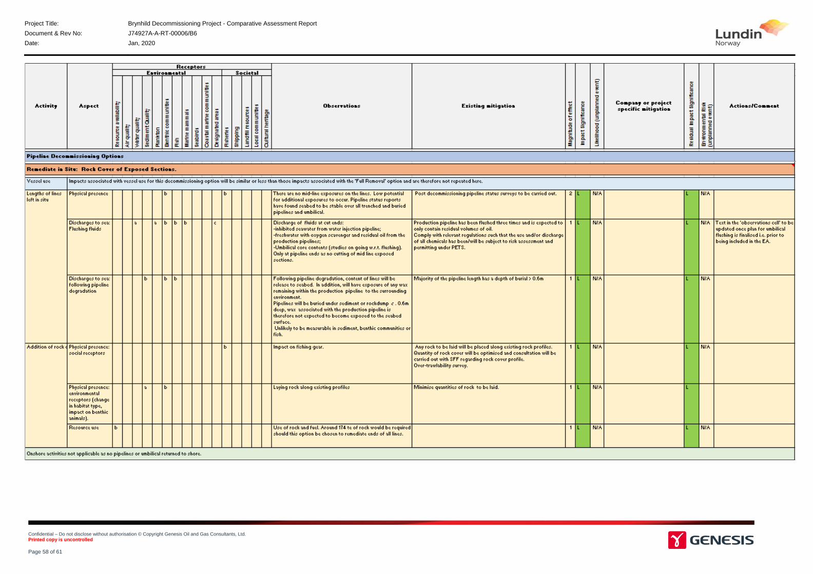
Project Title: Brynhild Decommissioning Project - Comparative Assessment Report
Document & Rev No: J74927A-A-RT-00006/B6
Date: Jan, 2020
Confidential – Do not disclose without authorisation © Copyright Genesis Oil and Gas Consultants, Ltd. Printed copy is uncontrolled Page 58 of 61

Project Title: Brynhild Decommissioning Project - Comparative Assessment Report
Document & Rev No: J74927A-A-RT-00006/B6
Date: Jan, 2020
Confidential – Do not disclose without authorisation © Copyright Genesis Oil and Gas Consultants, Ltd. Printed copy is uncontrolled Page 59 of 61

Project Title: Brynhild Decommissioning Project - Comparative Assessment Report
Document & Rev No: J74927A-A-RT-00006/B6
Date: Jan, 2020
Confidential – Do not disclose without authorisation © Copyright Genesis Oil and Gas Consultants, Ltd. Printed copy is uncontrolled Page 60 of 61
Where cut point is at the transition from an existing rock berm, existing rock cover will be re‐profiled locally to cover the cut end. No new rock cover will be imported
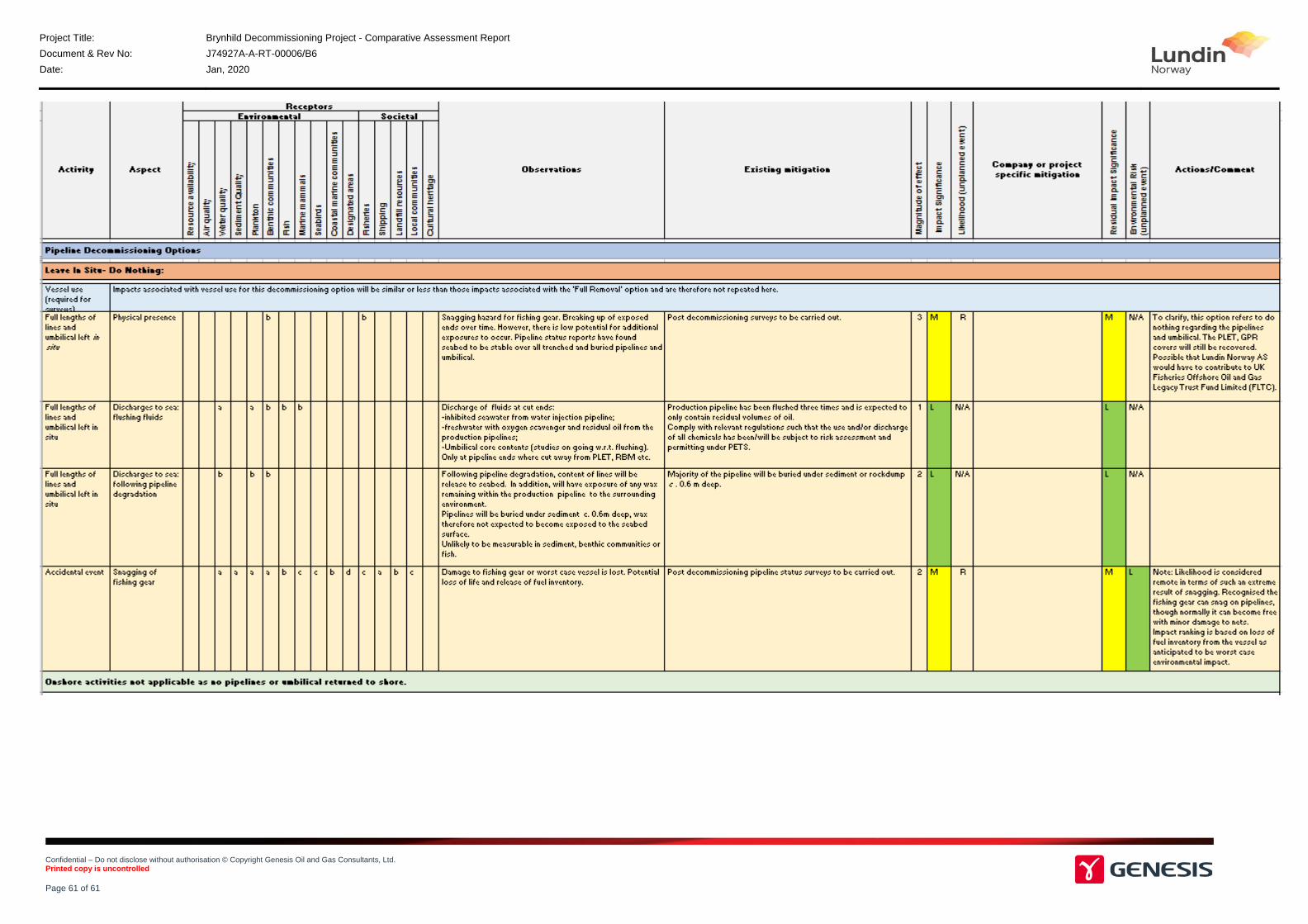
Project Title: Brynhild Decommissioning Project - Comparative Assessment Report
Document & Rev No: J74927A-A-RT-00006/B6
Date: Jan, 2020
Confidential – Do not disclose without authorisation © Copyright Genesis Oil and Gas Consultants, Ltd. Printed copy is uncontrolled Page 61 of 61