J. w. Vanderhoff, andY. N. Liu - Lehigh Universitydigital.lib.lehigh.edu/fritz/pdf/390_6.pdf · J....
61
,. POLYMER-IMPREGNATED CONCRETE: LABORATORY STUDIES E. Dahl-Jorgensen, W. F. Chen, M.ASCE, J. A. Manson, J. w. Vanderhoff, andY. N. Liu Fritz Engineering Laboratory, Materials Research Center and Center for Surface and Coatings Research Lehigh University Bethlehem, Pa. 18015 May 15, 1974 Submitted for publication by ASCE; also for presentation at the ASCE-EIC/RTAC Joint Transportation Convention, Montreal, Quebec July 15-19, 1974
Transcript of J. w. Vanderhoff, andY. N. Liu - Lehigh Universitydigital.lib.lehigh.edu/fritz/pdf/390_6.pdf · J....

,.
POLYMER-IMPREGNATED CONCRETE: LABORATORY STUDIES
E. Dahl-Jorgensen, W. F. Chen, M.ASCE, J. A. Manson,
J. w. Vanderhoff, andY. N. Liu
Fritz Engineering Laboratory,
Materials Research Center
and
Center for Surface and Coatings Research
Lehigh University
Bethlehem, Pa. 18015
May 15, 1974
Submitted for publication by ASCE; also for presentation at the ASCE-EIC/RTAC Joint Transportation Convention, Montreal, Quebec
July 15-19, 1974

•
•
POLYMER-IMPREGNATED CONCRETE: LABORA'IDRY STUDIES
KEY WORDS: bridges (structures); concrete (polymerimpregnated); deformation; ductility; durability; materials; permeability (salt); polymers; strength of materials; structural engineering; testing. •
ABSTRACT: To aid in the development of polymer-impregnated Portland cement (PIC) for highway bridge deck and other structural applications, a laboratory study of several process and material parameters was conducted. It was shown that (1) stress-strain behavior could be varied over a wide range, from ductile to brittle, by using combinations of a plasticizing and/or crosslinking comonomer with methyl methacrylate; (2) the presence of a realistic level of salt (up to 1%) in concrete has little effect on polymer loading and mechanical properties, but requires more rigorous drying; (3) while high temperatures (750°F) accelerate drying but decrease strength, subsequent polymer impregnation essentially yields a PIC with properties similar to a conventionally dried material; and (4) salt penetration (short-time, static) in mortars is reduced an order of magnitude by polymer impregnation, regardless of whether the polymer is glassy or rubbery. Thus, strong PICs can be prepared under a variety of drying and salt contamination conditions, and the mechanical behavior of PIC can be tailored to various specifications by varying polymer composition, without diminishing PIC's improved resistance to salt penetration.
REFERENCE: "Polymer-Impregnated Concrete: Laboratory Studies", E. Dahl-Jorgensen, w. F. Chen, M.A?CE, J. A. Manson, Y. N. Liu, and J. w. Vanderhoff, presented at the ASCE-EIC/RTAC Joint Transportation Convention, Montreal, Quebec, July 15-19, 1974 .
•
•
POLYMER-IMPREGNATED CONCRETE: LABORATORY STUDIESa
1 2 3 By E. Dahl-Jorgensen , W. F. Chen , M.ASCE, J. A. Manson ,
J. W. Vanderhoff4
, and. Y. N. Liu5
INTRODUCTION
Of the many new composites,one of the most interesting and poten-
tially useful in engineering applications is polymer-impregnated con-
crete (PIC). Previously-cured concrete is impregnated with monomer,
which is then polymerized within the pore system to give a composite
comprised of two interpenetrating networks-polymer and cement. Stein-
berg, Dikeou, et al. (6,16) have demonstrated that PIC composites show
remarkable mechanical properties and corrosion resistance. These re-
sults have been confirmed by studies of PIC in other laboratories (3-5,
9,11,14,15,18).
Because PIC effectively resists penetration by water and salt
solutions, several research programs (3,6,8,12,16) have been initiated
to apply PIC technology to highways, in particular, to bridge decks, in
which the corrosion of steel reinforcing rods by de-icing salts is a
pressing problem. In addition, the high levels of strength, modulus,
and toughness in PIC are of intrinsic interest in structural design
(3-5,9-11,14,15,18).
For the past two years, a major project on polymer impregnation
aPresented at the July 15-19, 1974, ASCE-EIC/RTAC Joint Transportation Convention, Montreal, Quebec; it was subsequently available as a ronference volume.
Res. Asst., Fritz Engineering Laboratory, Lehigh University, Bethl~hem, Pa. 18015. ·
Assoc. Prof., Dept. of Civil Engineering, Lehigh University, Bethlehem, Pa. 18015.
3prof., Chern., and Dir., Polymer Laboratory, Materials Research CenteE, Lehigh University, Bethlehem, Pa., 18015.
Prof., Chern., and Assoc. Dir., Center for Surface and Coatings Research, Lehigh University, Bethlehem, Pa. 18015.
5Res. Asst., Dept. of Chemical Engineering, Lehigh University, Bethlehem, Pa~ 18015.

of salt-contaminated but structurally sound bridge decks has been con
ducted by a joint Lehigh-Pennsylvania State University team (10). Paral
lel studies on controlling ductility in PIC by varying the composition
of the polyme~ have also been conducted in these laboratories (4,5,11).
The two subjects are obviously interrelated, for the ability of PIC to
resist salt penetration,especially after freeze-thaw cycling, may well
depend on the nature of the polymer used. Thus, both mechanical and
salt penetration behavior should be of interest in a variety of applica-
tions.
To support the specific problem of bridge deck impregnation in
the field, andm investigate more generally the interaction between
mechanical properties and salt permeability, laboratory studies of the
following phenomena were begun: (1) effects of residual salt on the
drying,impregnation,polymerization, and mechanical properties of PIC,
(2) high temperature (750°F) drying, (3) salt penetration into PIC of
various types, (4) optimization of the polymer composition in terms
of stress-strain behavior; and (5) inhibition of corrosion by impregna
tion. This paper describes progress with the first four subjects, using
methyl methacrylate (MMA), n-butyl acrylate (BA), and trimethylolpro
pane trimethacrylate (TMPTMA) as monomers, either alone or in various
combinations. Progress with the fifth subject, and with the impregna
tion of slabs in the laboratory, and a deck in the field, is described
separately (3,12).
CONCRETE AND MORTAR SPECIMENS
Typical Portland cement concrete cylinders, 3 x 6 in (7.5 x 15.2
em) in size were used for all tests except those of salt penetration,
for which standard Portland cement mortar cylinders, 1 x 2 in (2.5 x 5.1
em) in size, were used.
Concrete Cylinde~s.- One formulation for the concrete mix was used
throughout: water; type I Portland cement; fine aggregate, siliceous
2

•
stone crushed to a fineness modulus of 2.83; and coarse aggregate,
limestone having a maximum size of ~in (1.3 em) (both aggregates as
specified in ASTM C33-67). The respective weights were as follows:
1:2:4.3:4.7. As described below, four batches were made altogether;
two of the batches contained an air-entraining admixture, "Darex",
Table 1 shows the concrete mix, and Table 2 the recorded slump and en
trained air, for all four batches.
After compaction in 3 x 6 in (7.6 x 15.2 em) cylindrical cardboard
molds, and standing for 24 hr, the cardboard was removed and the specimens
were cured for 28 days in a foggy room at 90 to 100% R.H.
The Four Concrete Batches.- The four batches (Table 2) were mixed
and treated as follows (with appropriate controls in each case):
(1) Cylinders cast from the first mix, which contained no air
entraining admixture, are designated AI, AII, and BI to BIV. The AI
specimens were impregnated using MMA only, whereas the AII specimens
contained 60% MMA and 40% BA. Specimens BI to BIV were impregnated
with 10% TMPTMA together with various combinations of MMA and BA.
(2) Cylinders cast from the second mix, which contained no air
entraining admixture, are referred to as CI and CII. These specimens
were immersed in a 3% aqueous salt solution, CI twice and CII once,
after subsequent drying but before impregnation with MMA. This was
done to simulate the effect of salt contamination encountered in bridge
decks and its effect on strength and final polymer loading on the PIC.
(3) A third set of specimens, which did contain an air-entraining
admixture, was also prepared for salt contamination since it appeared
from experience with the CI and CII cylinders that longer drying
periods were required to reach constant weight, when salt was present.
These specimens were designated as D, DI, and DII.
(4) The fourth se~EI and EII, was prepared to investigate the
effect of two drying systems developed for use on concrete slabs (12).
3

, .. , Cylinders which were unimpregnated but otherwise similar to the spec-
imens in the four groups were used as controls in all cases.
Mortar Cylinders.- Standard Portland cement mortar cylinders, 1 x
2 in (2.5 x 5.0 em) were used for the salt penetration experiments;
MMA and BA monomer systems were used to represent a glassy and a rub-
bery polymer, respectively. The cylinders were prepared using a 12:24:
64 water-Type II Portland cement-Ottawa silica sand (ASTM C-109) mix
and cured under water for 28 days at room temperature.
DRYING AND SALT CONTAMINATION: CONCRETE
All concrete cylinders, except the EI-EII series and its controls,
were dried in a hot-air high-velocity oven to constant weight. Mortar
0 specimens were oven-dried as well, at 150 C for 3 hr. Since the latter
were not salt-contaminated, the following discussion refers to concrete
specimens only, whose treatments follow.
Specimens AI, AII, BI to BI~and their controls were dried at
260°F (l25°C) for 24 hr before impregnation.
After drying at 260°F (l25°C) for 24 hr, specimens CII were im-
mersed in a 3% salt (sodium chloride) solution for 24 hr, and then re-
dried at the same temperature for 24 hr before impregnation with MMA.
The CI specimens were treated in a similar manner, except for a repeti-
tion of the salt immersion before the final drying and impregnation(Table 3).
Since it was found that the ultimate strength of the CI and CII
PIC specimens were somewhat lower than expected, additional cylinders
were prepared for salt contamination, and constancy of weight after
drying carefully checked (initially, all specimens had been dried at
260°F (l25°C) for 24 hr). Specimens D were submerged in plain water,
whereas the DI and DII specimens were kept in the 3% salt solution for
48 hr before drying. The weight was recorded at the beginning of the
drying period, and at 17, 49, and 66 hrs at 260°F (l25°C). After an
average weight loss of 90 gm at l7'hr, constant weight was attained
4

•
for the D series specimens; drying was continued for an additional 32
hr for the DI and DII specimens.
After the first 17 hr of drying for the DI and DII specimens, the
average weight loss was 78 gm. During the next 49 hr they lost an addi
tional average weight of 10 gm, giving a total average loss of 88 gm,
close to the value noted for the D specimens. The DII cylinders were
finally immersed in the salt solution for 48 hr, and dried at 260°F
(125°C) for 60 hr. Table 3 shows the final weight percentages of salt
in the CI, CII, DI, and DII specimens.
In order to simulate drying of a bridge deck, drying tests (spec
imens EI) were also conducted using a propane burner constructed with a
hood directing the flame towards the concrete surface (12). An elec
tric motor moved the hood back and forth over an approximately 3-ft
(1.0 m) range (Fig.l). The 3 x 6 in (7.5 x 15.2 em) cylinders designated
EI were dried for 8 hr under 1 to 2 in of sand; the temperature in the
sand reached approximately 750°F (400°C). The recorded weight after
drying showed that the specimens had been thoroughly dried when com
pared to the oven dried specimens. No visible cracks were noted after
the drying had been completed.
A kerosene burner was also tried as a possible drying method for
bridge decks (specimens EII). As shown in Fig. 2, the burner forced
air at high velocity into a built-up enclosure. The airflow circulated
through the enclosure,and a thermostat shut the burner off and on when
the air temperature inside reached 250°F (120°C) or 225°F (107°C),
respectively. The drying of 16 3 x 6 in (7.5 x 15.2 em) cylinders
was conducted outside during and after a light rainfall for 12 hrs.
Since, however this procedure removed less than SO% of the estimated
free water in the specimens, these cylinders were removed from the
enclosure and oven dried at 260°F (l25°C) for an additional 12 hr
before impregnation.
5

•
IMPREGNATION AND POLYMERIZATION
With both concrete and mortar cylinders, 0.5% (by weight, based
on monomer) azo-bis-isobutyronitrile (AZN), dissolved in the desired
monomer, was used as polymerization initiator (4,5,10,11). Impregna
tion and polymerization were effected by slightly different means for
the concrete and mortar specimens.
Concrete Cylinders.- The vessel (Fig. 3) used for impregnation
of the 3 x 6 in concrete cylinders has been described in an earlier
investigation(4,5). Briefly, the vessel consists of a steel pipe welded
to a bottom flange and equipped with a cover which can be bolted to an
upper open flange.
After drying, the concrete cylinders were cooled down, placed in
the impregnation vessel, and subjected to both vacuum and pressure.
Air was removed from the specimens by a vacuum pump at 29 in of mercury
(100 KN/m2) for 1~ hr before the various monomer combinations contain~
ing 0.5% AZN was induced into the vessel. The vessel was then pressur
ized with nitrogen at 60 psi (414kN/m2) for 1~ hr to speed up the
penetration of monomer. After removal from the vessel the specimens
were polymerized under hot water at 160°F to 175°F (70 to 80°C) for 4
hr. This method has proved to be simple and to give little loss of
monomer in the specimens (14,15).
The polymer loading of the specimens after polymerization was
calculated as the increase in weight after polymerization in percent
of the initial dry weight. The polymer loadings are given in Table 4.
Mortar Cylinders.- After drying in an air oven for 3 hr at 150°C,
specimens were placed in a vacuum chamber and subjected to vacuum for
15 min, then immersed in monomer (MMA or BA) for 3 hr at atmospheric
pressure. The monomer-impregnated cylinders were then immersed in a
70°C water bath for 4 hr, to polymerize the monomer. These conditions
of drying, impregnating, and polymerization were sufficient to ensure
6
reasonably complete filling of the specimen void space. The polymer
loadings were 5-7%, based on dried weight.
MECHANICAL TESTS (CONCRETE)
Procedures.- A modification of the standard splitting tensile
test (ASTM C496-66) was developed for an earlier investigation (4,5).
The set-up, shown in Fig. 4,has the advantage that the lateral strain
can be automatically recorded as a function of load. A strain gauge
was glued to the bottom plane surface of each specimen, horizontally
in the center of the specimen.
The specimens used for compression tests (ASTM C39-66) were
capped with high-strength gypsum plaster to assure plane parallelism
of the ends. Two clip-type extensometers were fixed on either side of
the specimen between two rings. This set-up, also designed for an
earlier investigation (4,5), has proved to be reliable, capable of
reuse, and unaffected by the brittle, explosive failure of PIC (Fig. 5).
The load-strain relationships were recorded automatically on a
X-Y plotter for both the tension and compression tests.
Results.- Essentially uniform impregnation and complete conver-
sion to polymer were achieved for all the PIC specimens, as shown by
visual and microscopic examination, and by the observation of at most
a faint odor due to unreacted monomer (in only a few specimens on
freshly broken surfaces). The effects of salt content and of air-~
entrainment on final polymer loading are shown in Table~3;and 4. Earlier
studies with mortars containing up to 3% salt had shown a significant
decrease in monomer penetration rate, and in steady-state monomer
loading, in proportion to the amount of salt present (17). In con-
trast, at the 1% salt level used in this study, any decrease in load-
ing is masked by the normal range of variability from specimen to
+ specimen (about - 0.5%). A slight effect of air entrainment on load-
ing, due to the consequent increase in porosity, may, however be noted.
7

Table 5 lists the ultimate strengths and values of YoungYs modulus
(in compression) for all the specimens, and Figs. 6 to 15, inclusive,
give the stress-strain and load-strain curves themselves.
As shown in Figs. 6 and 7, the AI specimens, impregnated with 100%
MMA, display the now familiar linear stress (or load)-strain relation
ship (4-6,11,16) almost up to the point of ultimate brittle failure.
In comparison, the AII specimens, impregnated with a 60/40 MMA/BA mix~
ture, show a significant increase in ductility and only a 20% reduction
in strength compared to the AI specimens. These results agree well with
trends in results reported earlier for PIC's containing other composi
tions of MMA and BA (4,11), as well as with mortar specimens.
Effects of adding the crosslinking agent TMPTMA are shown in
Table 5 and Figs. 8 and 9, for specimens BI to BIV, inclusive; composi
tions are given in Table 4. It is seen that the addition of 10% TMPTMA
as crosslinking agent to various combinations of MMA and BA increases
the Young's modulus of PIC, but has a complex effect on strength.
While 10% TMPTMA causes a decrease in both tensile and compressive
strengths for the case of 100% MMA, the compressive strengths for the
MMA-BA combinations with TMPTMA pass through a maximum for a 60:30:10
mixture, the maximum value being similar to the value for 100% MMA.
In all cases, however, the use of TMPTMA tends to reduce ultimate strain,
and ductility (in the sense of yielding).
Figs. 10 and 11 show the stress (load)-strain behavior of the salt
contaminated specimens, CI and CII containing 0.8% and 0.4% salt, re
spectively. In this case 100% MMA had been used for impregnation.
Clearly, at least in these specimens, salt contamination prior to im
pregnation reduces the ultimate strength somewhat-by 15-20% in compres
sion, and by 30-37% in tension-though the reduction is small in com
parison with the relative increase due to impregnation. Results for
the DI and DII specimens(0.5% and 1.0% salt, respectively) which had
8
undergone extended drying prior to impregnation, are given in Figs. 12
and 13, along with data for the uncontaminated specimens D. Since the
DI and DII specimens all show higher loadings and higher strength than
the CI and CII series, the additional drying and air voids in the DI and
DII series appear to be ultimately responsible for the improved behavior.
As shown by Figs. 14 and 15, and Table S, high temperature drying
with the propane burner at 750°F (400°F) results in a 16% decrease in
tensile and compressive strengths of the high-temperature-dried spec
imens (EI) in comparison to the much less rigorously dried specimens
(EII). On the other hand, in compression, specimens EI exhibit as high
levels of strength as any observed in the study.
CHLORIDE PENETRATION IN PIC
In view of the generally improved resistance of PIC to corrosion,
e.g., by acids and sulfates (6,16), it may be expected that penetration
by chloride ion may also be reduced, in comparison with the unimpreg
nated matrix. However, several questions do arise: (1) in practice,
polymer impregnation does not fill all the available capillary pores;
(2) the matrix-polymer bond may conceivably undergo degradation during
service, especially under freeze-thaw cycling; and (3) in principle,
both the inherent permeability to salts and the stability of the matrix
polymer bond depend on the state of polymer (i.e., whether it is glassy
and brittle, or rubbery and tough).
To determine the relative effectiveness of various polymers in
PIC on reducing chloride penetration, static tests using standard Port
land cement mortar specimens are being conducted for a period of 18 mo;
similar tests (not reported here) under freeze-thaw cycling conditions are
also under way. Two monomers were used: MMA, which yields a glassy,
brittle polymer at room temperature, and BA, which yields a rubbery,
tough polymer. For the chloride determination, a new technique was
developed using electron microprobe analysis to follow salt migration
9

. '·
..
in the cement phase.
Procedures.- After impregnation by procedures described above,
the mortar cylinders were exposed to 8% aqueous CaC12·2H2o solutions
(13). Following the convenient procedure of Ost and Montfore (13),
solutions were contained in covered polyethylene sheaths tightly fitted
on the cylinders and adjusted to extend above the top surface for
about 1 in. The curved surfaces of the cylinders were closely wrapped
with waterproof tape to insure the axial flow; a screen support was
used to provide free circulation of air underneath. After different
exposure periods, cylinders were broken and the chloride concentration
determined at different depths by electron microprobe analysis (1,7).
At a given depth, small specimens were removed, coated with a thin
carbon layer (1,7), three areas in the cement phase--80 x 100 ~m (8
-3 ) x 10) x 10 cm)-scanned, and 10-sec counts (for chloride ion taken
in duplicate. Although the absolute numerical values include all
chloride content,and thus exceed those corresponding to "free" chloride
determinations by other techniques, the values provide a relative
measure of chloride ions available for corrosive reactions.
Results.- Preliminary results show that after only one month of
exposure, the plain mortar shows a significant amount of chloride
[1.6% Cl or 6% CaCl2·2H20) at a depth of 0.25 in (0.6 em)] at
different depths in the mortar (Fig. 16). Howeve1~for both BA and
MMA-impregnated mortars, only traces of chloride [ < 0.1% Cl(= 0.4%
CaCl2 ·2H20) by weight of cement paste] were found at a depth of 0.25
in. At lower depths, the chloride values from electron microprobe
fall into the range of background scatter, so that detection of deeper
penetration in the impregnated mortars will require much larger ex-
posure times. At least for a 1-mo exposure, both BA and MMA impreg-
nated mortars give similar results.
10

SUMMARY AND CONCLUSIONS
This study has demonstrated the preparation of a variety of PIC
composites under different drying conditions and with varying degrees
of salt contamination. The effects of such process parameters, and
also polymer composition, on stress-strain and salt-penetration charac
teristics have been studied selectively. Specific observations may
be summarized and conclusions drawn.
(1). As suggested in earlier studies (4,11), the brittle behavior
of PIC impregnated with MMA can be modified by incorporating a monomer,
BA, which confers a degree of rubberiness to the resultant copolymer.
A 60/40 MMA/BA combination shows a pronounced increase in ductility
compared to a 100% MMA impregnated specimen, at the expense of only
a 20% reduction in the ultimate strength.
(2). Incorporation of a crosslinking agent, TMPTMA, in the monomer mix
ture has several effects: a slight decrease in tensile and compressive
strengths in the case of MMA alone; a slight decrease in tensile strength
for all MMA/BA compositions studied (up to 40% BA); a slight decrease
to a negligible change in compressive strength, depending on the con
centration of BA; and a general reduction in ultimate strain and duc
tility, along with an increase in Young's modulus. Thus, a wide variety
of stress-strain and ductility characteristics can be obtained by· suit
able variation in monomer composition.
(3). Polymer loading is increased by the case of an air entrainment
agent, presumably due to a consequent increase in porosity.
(4). Although larger concentrations of salt are known to reduce poly-
mer loading (171 the presence of 1% sodium chloride in a matrix con-
crete has little practical effect on the amount of polymer loading
attainable, as long as specimens are dried adequately. Adequate drying
does appear to take longer with salt-contaminated than with uncontaminated
concrete. Well-dried salt-contaminated specimens show strengths and
11

..
!I
moduli at least as high as untreated ones, if comparison is made at
equal polymer loadings.
(5) In a separate study(9), high-temperature drying (750°F) has been
shown to be useful in the field impregnation of a bridge .deck. In this
study, it is seen that, although such drying may well induce cracRs and
microcracks which lower the strength of conc~ete, impregnation restores
or heals any cracks so that the -final PIC is as strong in compression,
and almost as strong in tension, as conventionally dried material.
(6) Impregnation of Portland cement mortar with polymers of MMA or
BA (glassy and rubbery, respectively) reduces calcium chloride pene-
tration, after 1 month's exposure to an 8% solution, by an order of
magnitude, regardless of the state (rubbery or glassy) of the polymer
used. Presumably, the behavior of copolymers, e.g., of MMA and BA,
will be similar. Completion of freeze-thaw cycling tests (in progress)
will, of course, be necessary to complete the picture of the role of the
polymer.
In conclusion, it may seen that use of polymer impregnation of
concrete can be effected under a range of drying and salt contamination
conditions, and that ductility and strength can be varied considerably
by changing the polymer composition, while maintaining improved static
salt permeability. These conclusions should be relevant to impregna
tion of bridge decks and to the design of PIC for structural applica-
tions in general.
ACKNCJNLEDGMENTS
Part of this work was conducted within NCHRP Project 18-2, "Poly-
mers in Highway Concrete" (Lehigh and Pennsylvania State University),
Prine. Invest., J. A. Manson, ~nd was sponsored by the American Asso-
ciation of State Highway Officials, in cooperation with the Federal
Highway Administration, conducted in the National Cooperative Highway
Research Program, which is administered by the Highway Research Board
12

of the National Academy of Sciences - National Research Council.
(The opinions and conclusions expressed or implied in this paper are
those of the research contractor. They are not necessarily those of
the Highway Research Board, the National Academy of Sciences, the
Federal Highway Administration, the American Association of State
Highway Officials, or of the individual states participating in the
National Cooperative Highway Research Program.) Partial support by
the Pennsylvania Science and Engineering Foundation, Department of
Commerce, Commonwealth of Pennsylvania, is also gratefully acknowl
edged. Invaluable assistance with experimental work was provided
by H. C. Mehta.
Table 1: Concrete mix
Water/cement ratio (by weight) 0.5
Water,lb (kg) 24.4 (11.1)
Cement,lb (kg) 48.8 (22.1)
Sand,lb (kg) 104.5 (47.4)
Coarse aggregate,lb (kg) 113.5 (51. 5)
13

Table 2: Concrete mix properties
Air-entraining Entrained Slump in admixture "Darex", in air, inches(centimeters) cubic centimeters %
AI,AII; BI-'BIV; controls 0 5 2 (5)
CI,CII; controls 0 4 2 (5)
D; DI, DII; controls 10 7 2. 75 (7)
EI,EII; controls 7.5 6 2.5 (6.4)
Table 3: Salt contamination in PIC
Specimen weight percent salt in Series dry specimens
CI 0.8
CII 0.4
D o.o DI 0.5
DII 1.0
14

Table
Specimens Number of Specimens.
AI 4
AII 8
BI 4
BII 8
BIII 8
BIV 8
CI 8
CII 8
D 8
DI 8
DII 8
EI 8
EII 8
4: Polymer Loading
Polymer
100% MMA
60% MMA + 40% BA
90% MMA + 10% TMPTMA
70% MMA + 20% BA + 10% TMPTMA
60% MMA + 30% BA + 10% TMPTMA
SO% MMA + 40% BA + 10% TMPTMA
100% MMA
100% MMA
100% MMA
100% MMA
100% MMA
100% MMA
100% MMA
15
Average Polymer
(% Loading by
4.8
4.3
5.2
4.6
4.9
5.1
5.1
4.9
7.7
7.7
7.1
7.4
6.8
weight)

Table 5: Ultimate strengths
... Specimen Tensile Compressive Young' s modulus*
strength strength2
ksi x 103 (kN/mm2) ksi (N/mm2) ksi (N/mm )
AI 1.38 (9.52) 18.6 (128.6) 7.5 (51. 8)
AII 1.13 (7.81) 14.4 ( 99.1) 4.0 (27.9)*
A control o.so (3.42) 5.5 ( 38.0) 3.4 (23.2)*
BI 1.10 (7.57) 16.1 (110.9) 7.8 (53.7)
BII 0.94 (6.47) 16.4 (113.4) 7.1 (49.3)
BIII 1.01 (6.98) 18.4 (126.7) 7.1 ( 49.3)
BIV 1.18 (8.15) 17.8 (122.7) 7.1 (49.3)
B control 0.44 (3.05) 5.4 ( 37.0) 4.1 (28.3)*
CI 0.87 (5.98) 15.9 (109.9) 5.7 (39.4)
CII 0.90 (6.22) <14.9 (103.0) 5.7 (39.4)
CI control o. 48 (3.29) 5.0 ( 34.5) 4.4 (30.3)*
CII control 0.51 (3.54) 3.8 ( 26.1) 3.6 (24.6)*
D l. 45 (10.01) 19.6 (135.2) 6.7 (45.9)
DI l. 40 (9.64) 18.8 (129.7) 5.8 (40.0)
DII 1.38 (9.52) 19.9 (137.3) 6.3 (43.5)
D control 0.39 (2.68) 4.2 ( 29.9) 2.3 (15. 5P" DI control 0.42 (2.93) 4.5 ( 31.1) 2.9 (19.7)*
DII control o. 47 (3.22) 4.8 ( 31.1) 3.6 (24.5)*
EI 1.18 (8.18) 19.4 (133.9) 6.4 (43.8)
EII l. 47 (10.13) 19.6 ('135.2) 6.4 ( 43.8)
EI control 0.42 ( 2. 93) 4.7 ( 32.4) 3.4 (23.1)*
EII control 0.50 ( 3.42) 5.6 ( 38.6) 3.7 (25.2)*
*Young's modulus for AII and all controls is the "secant modulus" measured at a stress one-half the ultimate value. The "tangent modulus" is given for the other specimens. Values based on compressive tests.
16

" APPENDIX I. - REFERENCES
1. ·Abd-El-Bary, M., Manson, J. A., and Goldstein, J. I., "Electron Microprobe Investigation into the .Diffusion of Ions through Polymers", Journal of Materials Science (London), Vol. 5, 1970, pp. 898-900.
2. Berman, H. A., "Determination of Chloride in Hardened Portland Cement Paste, Mortar, and Concrete". Report No. FHWA-RD-72-12, Federal Highway Administration, Sept., 1972.
3. Cady, P. D., "Development of Field Methods for the Use of Polymer Impregnated Concrete in Bridge Deck Applications", presented at the ASCE-EIC/RTAC Joint Transportation Convention, Montreal, Quebec, July, 1974; see also this journal, pp.
4. Chen, W. F. and Dahl-Jorgensen, E., "Polymer-Impregnated Concrete as a Structural Materialn. Magazine of Concrete Research, Vol. 26, No. 86, March 1974, pp. 16-
5. Chen, W. F., and Dahl-Jorgensen, E., "Stress-strain properties of Polymer Modified Concrete". Polymers in Concrete. American Concrete Institute Publication SP40-17, 1973, pp. 347-358.
6. Dikeou, J. T., et. al., "Concrete-Polymer Materials, Fourth Topical Report", USBR REC-ERC-72-10 & BNL 50328, Brookhaven National Laboratory, Upton, N. Y., and U. S. Bureau of Reclamation, Denver, Col., Jan., 1972.
7. Fletcher, K. E., "Electron Probe Analysis of Silicate Building Materials", Chemistry and Industry (London), Sept., 1969, pp. 1325-1328.
8. Fowler, D. W., Houston, J. T., and Paul, D. R., "Polymer-Impregnated Concrete Surface Treatments for Highway Bridge Decks", paper presented at symposium on Polymers in Concrete, American Concrete Institute meeting, Atlantic City, N. J., March, 1973.
9. Manning, D. G. and Hope, B. B., "The Influence of Porosity and Partial Drying on Properties of Polymer Impregnated Mortar". Polymers in Concrete.American Concrete Institute Publication SP 40-9, 1973, pp. 191-203.
10. Manson, J. A., Chen, W. F., Vanderhoff, J. w., Cady, P. D., and Kline, D. E., Quarterly Reports, NCHRP Project 18-2 "Polymers in Highway Concrete", Lehigh and Pennsylvania State Universities, 1972-1974.
11. Manson, J. A., Chen, W. F., Vanderhoff, J. W., Liu, Y.-N., DahlJorgensen, E., and Mehta, H., "Stress-Strain Behavior of PolymerImpregnated Concrete", Polymer Preprints, Vol. 14, No. 2, Aug., 1973, pp.l203-1209.
12. Mehta, H. c., Chen, W. F., Manson, J. A., and Vanderhoff, J. W., ''Polymer-Impregnated Concrete: Field Studies"· presented· at the ASCEEIC/RTAC Joint Transportation Convention, Montreal, Quebec, July, 1974; see also this journal, pp.
17

• 13 • Ost, B., and Monfore, G. E., "Penetration of Chloride into Concrete 71 , Journal of the PCA Research and Development Laboratories, Vol. 8, No.1, Jan., 1966, pp. 46-52.
14. Sopler, B., Project Cl49. Polymerbetong. (Concrete-polymer mateials.) Report No. 2, Trondhe~m, Cement and Concrete Research Inst~tute of the Technical University of Norway, January,l971. (In Norwegian, summary in English).
15. Sopler, B., Project Cl49. "Polymerbetong". (Polymer-concrete mateials.) Report No. 3. Field test using polymerized curb stones. Trondheim, Cement and Concrete Research Institute of the Technical University of Norway, December,l971. (In Norwegian, summary in English).
16. Steinberg, M. et al., "Concrete-Polymers, Second Topical Report", USBR REC-OCE-70-1 & BNL 50218 (T-560), Brookhaven National Laboratory, Upton, N. Y., and U.S. Bureau of Reclamation, Denver, Col., Dec., 1969.
17. Vanderhoff, J. W. , Hoffman, J. D. , and Manson, J. A. , "PolymerImpregnated Concrete: Rate of Penetration of Monomer", Polymer Preprints, Vol. 14, No.2, Aug., 1973, pp. 1136-1142.
18. Whiting, D. A. , Blankenhorn, P. R. , and Kline, R. E. , "Epoxy Impregnation of Portland Cement Concrete", Polymer Preprints, Vol. 14, No. 2, Aug., 1973, pp. 1154-1156.
18

Fig . 1. Propane burner for drying concrete.
Fig . 2. Kerosene burner for drying concrete .
19

Fig. 3 . Monomer impregnation vessel for concrete .
Fig. 4. Splitting tensile test.
20

•
Fig. 5. Compression test : (A) Test set up •
Fig. 5. Compression test : (B) Close-up of the strain measuring device.
21

•
•
•
100~
0 100 200 300 400 500 TENSILE STRAIN, in./ in. x 10- 8
Fig. 6. Tensile load-strain curves for concrete impregnated with MMA/BA (60/40) mixture.
15 100 An
en ...: N
E en- 10 E (/) ...... w z a:: ~ 50 (/)
0 2000 6000 COMPRESSIVE STRAIN, in./in. x 10- 8
Fig. 7. Compressive stress-strain curves for concrete impregnated with MMA/BA (60/40) mixture.
22

•
•
0
BISZ: 150
I 00 . 200 300 400 TENSILE STRAIN, in./ir:t x 10-6
100 z ::.:::
Fig. 8. Tensile load-stress curves for concrete • impregnated with various combinations of MMA, BA, and TMPTMA (Table 4).
15
ui 10 fJ)
w cr 1-fJ)
em
~--- Control
0 1000 2000 3000 COMPRESSIVE STRAIN, in./ in. x 10-6
50
N
E E ....... z
Fig. 9. Compressive stress-strain curves concrete impregnated with various combinations of MMA, BA, and TMPTMA (Table 4).
23

..
150
CI Q.
100 z ~
err Control
C I Control 50
0 100 200 300 TENSILE STRAIN, in./in. x 10- 6
Fig. 10. Tensile load-strain curves for saltcontaminated concrete impregnated with MMA (Tables 3, 4).
CI 15 en 100
00"10 C/) w a:: 1-C/)
0 1000 2000 3000 COMPRESSIVE STRAIN, in./in.x 10- 6
50
N
E E ....... z
Fig. 11. Compressive stress-strain curves for salt-contaminated concrete impregnated with MMA (Tables 3, 4).
24

• 150
100~
0 100 200 300 TENSILE STRAIN, in./in.x 10-1
Fig. 12. Tensile load-strain curves for saltcontaminated concrete impregnated with MMA (Tables 3, 4).
1000 2000 3000 4000 COMPRESSIVE STRAlN, in./in.x 10-e
DII DI
100
!SO
... E ~ z
Fig. 13. Compressive stress-strain curves for salt-contaminated concrete impregnated with MMA (Tables 3, 4).
25

•
0
Fig. 14.
20
15
0
100 TENSILE
----En Control
100 z :lil::
----EI Control 50
Tensile load-strain curves for concrete dried with the propane and kerosene burners and impregnated with MMA. (Table 4).
EI
-----En Control =---- E I Control
100
N
50
E E
...... z
Fig. 15. Compressive stress-strain curves for concr.ete dried with the propane and kerosene burners and impregnated with MMA (Table 4).
26

(f) w J: u z
·z
J: .... a.. w 0
..
2
o •: PBA Impregnated
ll. &: PMMA Impregnated
0 0.5 1.0 1.5 PERCENT OF CHLORINE BY WEIGHT OF CEMENT PASTE
Fig. 16. Effect of polymer impregnation on chloride penetration in Portland. cement mortar cylinders after 1-mo immersion in 8% calcium chloride solution.
0
-N •a )(
2-(f) a:: w .... w ~
z
4~
2.0
a.. w 0

•
..
•
POLYMER-IMPREGNATED CONCRETE: FIELD STUDIES
H. C. Mehta, J. A. Manson, W. F. Chen, M.ASCE, and J. W. Vanderhoff
Fritz Engineering Laboratory
Materials Research Center,
and
Center for Surface and Coatings Research
Lehigh University
Bethlehem, Pennsylvania 18015
May 22, 1974
Submitted for publication by ASCE; also for presentation at the
ASCE-EIC/RTAC Joint Transportation Convention
Montreal, Quebec, Canada
July 15-19, 1974

•
POLYMER-IMPREGNATED CONCRETE: FIELD STUDIES
KEY WORDS: bridges (structures); concrete (polymer-impregnated); construction materials; corrosion; drying; durability; materials testing; polymers; polymerization (steam); slabs.
ABSTRACT: The principles developed in the laboratory for polymer impregnation of concrete to depths below the top layer of steel reinforcing rods were applied to the impregnation of large concrete slabs and a bridge deck. These principles include drying of the concrete to the desired depth of impregnation, allowing sufficient time for complete impregnation with monomer (e. g •• using pressure to increase the rate of penetration), and selecting the monomer, not only for its cost and the properties of its polymer, but also for its rate and uniformity of penetration. The concrete slabs and bridge deck were dried thoroughly using a propane torch assembly (temperature at surface 700°F or 372°C, at 4-inch (10-cm) depth 250° F or 121 o C), impregnated with a 16-in (41-cm) diameter pressure impregnator at 15-80 psi (104-552 kN/m2), wrapped or covered with a polyethylene film, and polymerized for 5-8 hours using steam from a pressure cooker. The monomer was a 90:10 methyl methacrylate-trimethylolpropane trimethacrylate mixture containing 0.5% azobisisobutyronitrile initiator. The slabs were impregnated to their full 6-inch (15-cm) thickness, the bridge deck to a depth of at least 5 inches (12.5 em). The polymer-impregnated slabs show increased compressive and split-tensile strengths, decreased water absorption, and improved resistance to corrosion, freeze-thaw cycling, abrasion, and acid-etching. The polymer-impregnated bridge deck shows decreased water absorption and improved resistance to acid-etching. These improvements give promise of exceptional durability in practice.
REFERENCE: "Polymer-Impregnated Concrete: Field Studies," H. C. Mehta, J. A. Manson, W. F. Chen, M.ASCE, and J. W. Vanderhoff, presented at the ASCE-EIC/RTAC Joint Transportation Convention, Montreal, Quebec, July 15-19, 1974 .

•
•
•
POLYMER-IMPREGNATED CONCRETE: F1ELD STUDIESa
By H. C. Mehta1, J. A. Manson2, W. F. Chen3, M.ASCE, and J. W. Vanderhoff4
INTRODUCTION
Every highway department is confronted with the problem of deterioration of concrete
bridge slabs, as well as reduced skid resistance and unacceptable wear rates of their surfaces.
In large part, this deterioration is the result of cracking and spalling of the concrete, which
in turn is the result of its property deficiences - high permeability, low strength, poor dur
ability, sensitivity to freezing and thawing. The deterioration eventually results in corrosion
of the top layer of steel reinforcing rods. The extensive use of deicing salts during winter
increases the salt concentration in the bridge deck to a critical level, so that it permeates
through the surface cracks and the highly-permeable concrete surface layer down to the rein
forcing rods and causes their corrosion. This corrosion is aggravated by successive freezing
and-thawing cycles which cause subsurface fractures and surface potholes in the concrete.
Other mechanisms of deterioration are also operative, e. g., differential expansion and con
traction and high wear rates due to high traffic loads and studded tires.
Various methods have been tried to protect the bridge deck surfaces, e. g. , waterproof
ing the surface with coatings, membranes, or overlays, coating the reinforcing steel with
epoxy resins, and repatching the potholes. All of these methods alleviate the problem tem
porarily, but none shows promise of long-term protection or reduction in repair costs.
Eventually, all of the systems break down, resulting in penetration of salt solution, corrosion
of the reinforcing steel, and spalling of the concrete. The spalling - the primary cause of
this deterioration -could be prevented if the macrocracks, micropores, and microcap
illaries of the concrete layer above the reinforcing steel were sealed with an impermeable
solid substance that would prevent penetration of the salt solution.
One approach to achieve this objective is the use of polymer-impregnated concrete(7-9, ·
12, 13, 18-20) In hi h . 1 ed . d ·oo th t · . t s approac , previous y-cur concrete 1s r1 to remove e wa er
from its void spaces and impregnated with a liquid monomer or prepolymer which fills these
aPresented at the July 15-19, 1974, ASCE-EIC/RTAC Joint Transportation Convention, Montreal, Quebec; it was subsequently available as a conference volume ..
1 Res. Asst., Fritz Engineering Laboratory, Lehigh University, Bethlehem, Pa., 18015. 2Prof., Chern., and Dir., Polymer Laboratory, Materials Research Center, Lehigh
University, Bethlehem, Pa., 18015. 3 Assoc. Prof., Dept. of Civil Engineering, Lehigh University, Bethlehem, Pa., 18015. 4Prof., Chern., and Assoc. Dir., Center for Surface and Coatings, Lehigh University,
Bethlehem, Pa. , 18015.

•
voids; then, the monomer or prepolymer is polymerized to form an interpenetrating network
of polymer throughout the concrete. These polymer-impregnated-concrete composites have
been shown to be impermeable to water and salt solutions, and to have superb resistance to
freezing-and-thawing, chemical attack, and abrasion; moreover, their compressive, tensile,
dtl bo at h h f (7,8,13,18,19) an exural strengths are a ut 30070 greater t an t ose o unmodified concrete •
Although these excellent properties of polymer-impregnated concrete have been demon
strated in the laboratory, the technology for its application to bridge decks in the field has
not yet been developed. The ultra:fine pore structure of concrete makes it difficult to dry and
impregnate thick concrete slabs to a sufficient depth. The problem is complicated by the fact
that the methods that were so successful in the laboratory are not directly applicable to the
field, e. g., the bridge deck cannot be put into an oven for drying or into a pressure chamber
for impregnation. In the field, the <;lrying and impregnation of the slabs would almost cer
tainly have to be accomplished from one side of the slab.
Earlier work at the Brookhaven National Laboratory and the U.S. Bureau of Reclamation
<7' 8• 18• 19) and the University of Texas at Austin (9
) showed that 2-inch (5-cm) penetrations
of new or badly-deteriorated decks could be achieved within a reasonable time by surface
drying and monomer-ponding (i. e. , impregnation at atmospheric pressure) techniques. The
goal of the Lehigh-Pennsylvania State University team (13
), however, is to achieve a 4-inch
(10-cm) penetration in sound salt-contaminated decks. Such a penetration would allow the
interpenetrating network of polymer to envelope the top layer of reinforcing steel and seal
off the capillary channels of the concrete, to prevent the permeation of salt solutions and sub
sequent corrosion of the steel. To accomplish this deeper penetration requires greatly
enhanced rates of drying and impregnation because:
(1) Both the rate of water evaporation and monomer impregnation are proportional to the
square root of time (13
' 20
), so that the deeper the desired depth of drying or impregnation,
the longer the time required to achieve it, e. g. , it takes 5 days to achieve a 6-inch (15-cm)
penetration into thoroughly-dried concrete using the monomer-ponding technique (13
) (also
see Figure 7).
(2) The rates of drying and impregnation of salt-contaminated concrete are slower than
those of uncontaminated concrete (2
0) (also see Table I) because the salt clogs the capillary
pores and restricts the movement of water and monomer.
The purpose of this paper is to describe the current status of work carried out to over
come these problems and develop field drying and impregnation techniques.
2

•
WORK DETAILS
The experimental work on 24 x 24 x 6 inch (61 x 61 x 15 em) thick concrete slabs comprised
the following:
(1) Development of apparatus and techniques for impregnation of the slabs with various
monomer systems.
(2) Evaluation of the effectiveness of the technique in terms of:
(a) the properties and condition of the concrete slab;
(b) the drying of the slab preparatory to impregnation;
(c) the properties of the polymer-impregnated concrete, especially durability, skid
resistance, abrasion resistance, strength, and permeability.
(3) Demonstration of the techniques in the field, with the goal of schieving a 4-inch pene
tration.
I. Test Specimens. The 24 x 24 x 6 inch concrete slab specimens were prepared from a
conventional non-air-entrained 1.00:1.92:6.10:6.75 water-portland cement (type 1)-coarse
sand-limestone aggregate (1 inch or 2.5 em maximum) mix with a cement factor of 485 lbs/yd3
(287 kg/m3) and 28-days-average compressive strength of 4750 psi (32800 kN/m2). The mea
sured air content was 3% with slump of 2.5-3.0 inches (6.35-7.62 em). ·The slabs were given
a normal trowel finish and were cured in the fog room (90-100% relative humidity) for at
least 28 days before use in drying and impregnation tests. All slabs contained a nominal
steel reinforcement at a 4-inch (10-cm) depth to simulate the structure of the bridge deck.
II. Drying of the Concrete Slabs. The major problem in achieving deep impregnations in
. d t d . th h h . (10,11,13,17) h concrete 1s a equa e ry1ng ra er t ant e monomer penetration per~ . . T e
monomer or prepolymer impregnant fills only those yoid spaces from which the water has
been removed by drying, so that the penetration proceeds until the impregnant reaches the
water remaining in these spaces and then stops. •
There is little information in the literature on the drying of concrete, and what informa
tion is available describes the slow drying at low temperatures (i. e. , less than 100° C). These
low temperatures require unacceptably long times to dry a bridge deck adequately for mono
mer impregnation, e. g., the use of such methods as natural heating, infrared heating, elec
tric blankets, or a combination of these methods, requires from 3 to 30 months to adequately
dry a bridge deck (1). Thus, to prepare polymer-impregnated concrete, the drying must be
carried out at temperatures above 100° C in order to remove water to the desired depth
within a practical time <16).
To determine the rate of drying, the 6-inch (15-cm) thick slabs were heated in an oven
3

at 250° F (121 o C), and their weights were determined at various times using an insulated
load cell. Figure 1 shows a slab mounted in the oven with the arrangement for measuring
the load, and Figure 2 shows a typical drying-rate curve. The results of many such exper
iments showed that the drying was complete within about 45 hours. Moreover, the rate of
water loss was proportional to the square root of the drying time, indicating that the drying
process is diffusion-controlled. These results for the 6-inch (15-cm) thick slabs dried from
both sides are equivalent to a 3-inch (7 .5-cm) thick slab dried from only one side.
To develop suitable methods for drying concrete slabs in the field, drying experiments
were carried out using a fixed propane torch assembly (Figure 3) to dry both small and
large slabs in the laboratory as well as a bridge deck in the field. The details of these drying
experiments will be reported elsewhere<14
); however, this flame-drying method compares
well with drying methods used by others, e. g. , gas-fired infrared, radiofrequency, micro
wave, hot air, and electro-osmotic drying(2
, 5' 13
). This method gives high surface temper
atures (e. g., 700° For 372° C), which means potential savings in time and labor. For exam
ple, in drying a 72 x 72 x 8 inch (183 x 183 x 20 em) concrete slab (PennDOT A-A specification),
only 7.5 hours were required for the temperature at the 4-inch (10-cm) depth to reach 250° F
(12rC), and in drying a bridge deck in the field at subfreezing temperatures, only 9 hours
were required for the temperature at the 4-5-inch (10-13-cm) depth to reach 250° F. Tem
peratures such as these make it practical to dry and impregnate concrete to the depths
reported here (6 inches (15 em) in the laboratory and 5 inches (12.5 em) in the field).
Ill. Impregnation and Polymerization. The completely-dried 24 x 24 x 6 inch (61 x 61 x 15 em)
concrete slabs were positioned on supports with their lower surfaces exposed and subjected
to impregnation from their upper surfaces. Figure 4 shows a conceptual representation of a
pressure impregnation device, and Figure 5 shows a prototype device based on this concept
used on the 6-inch (15-cm) thick slabs. This prototype device consisted of a 6x 10 inch
(15 x 25 em) chamber welded to a 20 x 20 x 1 inch (51 x 51 x 2.5 em) steel plate. This chamber
was equipped with suitable gages and valves to permit convenient filling with monomer anp
pressurization during impregnation. It was also equipped with a vacuum pump to evacuate
the concrete substrate before impregnation. The device was fitted with a 16-inch (41-cm)
circular gasket and bolted to the slab. This method of attachment was used to equalize the
pressure so as not to exceed the maximum allowable live load for bridge decks (usually 150
• psi or 10.6 kg/cm2). The monomer mixture used was a 90:10 methyl methacrylate (MMA)
trimethylolpropane trimethacrylate (TMPTMA) or isobutyl methacrylate (IBMA)-trimethylol
propane trimethacrylate mixture containing 0.5% azobisisobutyronitrile (AZN) initiator.
4

•
The first slab was dried and impregnated at a pressure of 30 psi (207 kN/m2). After
17 hours, a dark spreading patch of monomer appeared on the underside of the slab; by 24
hours, this patch bad grown to a diameter of 18 inches (46 em), larger than the diameter of
the area impregnated from the upper surface. At this point, the impregnation device was
removed, and a 0.5-inch (1.3-cm) layer of sand was spread over the area enclosed by the
gasket and wetted with additional monomer, to minimize evaporative losses during poly
merization<9•13>. The slab was then wrapped in polyethylene film, and live steam was
played on its surface for 5 hours to polymerize the monomer mixture. After polymerization,
the polymer loading of this slab was determined to be about 5.5%.
When the slab was broken, only a slight odor of monomer was detected, indicating that
the polymerization had proceeded to high conversion. Moreover, the appearance of the
fracture cross-section (Figure 6) was similar to that of other polymer-impregnated speci
mens. The dark polymer-impregnated region can readily be distinguished from the light
unimpregnated region. The diameter of the impregnated region was 21 inches (53 em) on the
upper surface and 18 inches (46 em) on the lower surface of the slab, indicating that the
impregnating monomer had spread laterally beyond the 16-inch (41 em) diameter enclosed
by the gasket. Also, the lighter 0.25-inch (0.64-cm) surface layer on the bottom indicated
that some monomer was lost from the lower surface by evaporation. Examination of the
fracture cross-section with a magnifying glass showed that, in the polymer-impregnated
region, fracture occurred through the aggregate particles, but in the unimpregnated region,
it occurred around the particles.
Despite these minor deficiencies, this first slab impregnation was successful in that it
achieved the deepest impregnation in sound concrete reported to date. To confirm and ex
tend this result, other slabs were dried and impregnated (Table 1). The parameters inves
tigated included the pressure applied during impregnation, evacuation after drying and be-. . fore impregnation, the substitution of isobutyl methacrylate for methyl methacrylate in the
monomer mixture, the use of hot-water ponding instead of steam to polymerize the mono
mer, and the presence of salt as a contaminant in the concrete substrate.
In these experiments, the pressure was varied from 30 to 80 psi (207 to 552 kN/m2).
The impregnation proceeded smoothly in all cases, but there was some leakage of monomer
around the gasket at pressures greater than 60 psi (414 kN/m2). An increase in the pres-
• sure decreased the time required for penetration to the full 6-inch (15-cm) depth, e. g. ,
from 17-24 hours for 30 psi to 2.0-3.5 hours for 80 psi. These times are expressed as
ranges; the first value denotes the first appearance of monomer on the underside of the
slab, and the second value the time required for complete impregnation. Apparently, the
5

•
monomer mixture penetrates first through the channels and microcracks from which the
water has been removed and only later fills the micropores and large voids as it spreads
both downward and laterally through the slab.
Figure 7 shows the variation of percent penetration (based on a 6-inch (15-cm) slab
thickness) with time as a function of applied pressure. The rate of penetration increased
strongly with increasing pressure. These results may be combined with the relationship
developed earlier(13 • 20) to ~elate the depth of penetration h into mortar or concrete of
given porosity to the time.!. and pressure gradient t:J. P to give the equation:
(1)
where K1 is a function of the pore radius and contact angle of the monomer on the concrete
substrate, and y and 11 are the surface tension and viscosity, respectively, of the mono
mer mixture. Thus, the depth of penetration h varies linearly with tl.P instead of with 1
(AP)2 as predicted by the usual analysis of capillary forces. Therefore, the time re-
quired to reach a given depth his proportional to ~2. Evacuation was used on all slabs described in Table I except slab 1A. Slab 2 was
evacuated for 2.0 hours at 25 inches (63.5 em) Hg, but all other slabs were evacuated for
1.5 hours at 28 inches (71 em) Hg.
Isobutyl methacrylate was substituted for methyl methacrylate in two slabs in this
study because it is less volatile and therefore less subject to loss by evaporation. More
over, polyisobutyl methacrylate is more flexible and less brittle than polymethyl meth
acrylate and thus may be better able to withstand repetitive freezing-and-thawing cycles.
All of the slabs were polymerized for 5-8 hours using steam except slab 2 which was
polymerized overnight using hot-water ponding on its surface. During the course of the
polymerization, the temperature of the water dScreased from 140° F (60°C) to 100° F (43°C),
and some monomer was lost by evaporation from the underside of the slab.
The effect of salt contamination is shown by slabs 2 and 5, which were dried to con
stant weight, soaked in salt solution to constant weight, and then redried to constant weight.
From the increase in weight, slab 3 contained 0.25-0.35% salt and slab 5 0. 70-0.85% salt;
the difference was attributed to the higher concentration of salt solution in which slab 7 was
soaked. Table I and Figure 7 show that slightly slower rates of penetration and slightly
lower polymer loadings were observed for the salt-contaminated slabs (4.5% and 5.0% as
compared with 5.0-5.5% for uncontaminated slabs). In comparison, the maximum salt con
centration found in bridge decks is usually less than 0.3% and the salt contamination is
6

•
usually limited to the top 2-inches (5.1 em) of the deck (13
), so the decrease in rate of pene
tration observed here may not be significant in the field.
Figure 7 also compares results for atmospheric-pressure impregnations of a 4-inch
(10-cm) core taken from a salt-contaminated bridge deck and a 3 x 6 inch (7 .6 x 15.2 em)
cylinder prepared in the laboratory. The core and cylinder were dried completely and im
pregnated from one surface. The time required for impregnation to the 6-inch depth was
greater for the bridge deck core than for the laboratory cylinder. Possible reasons are
salt contamination plugging the pores, a different porosity of the concrete, or both.
The morphology of the polymer-impregnated specimens shows the efficacy of the
pressurized impregnation method. Figure 8 compares fracture cross-sections of cores
from salt-contaminated unimpregnated concrete slab 5 and polymer-impregnated concrete
slab 2; Figure 13 shows the acid-etched and polished core sections from various slabs
after freeze-thaw testing; Figure 14 shows the acid-etched and polished core sections
taken from the polymer-impregnated bridge deck. In all cases, the polymer-impregnated
regions can be distinguished from the unimpregnated regions by the difference in color
ation; all polymer-impregnated samples show a uniform dark coloration that indicates
the completeness of the impregnation. Also, fracture cross-sections of slabs 6 and 7
(in which the impregnation was deliberately terminated before it was complete) show a
well-defined and uniform boundary between the unimpregnated and polymer-impregnated
regions; this boundary is 2.00-2.25 inches (5.1-5. 7 em) below the surface for slab 6 and
3.25-3.50 inches (8.3-8.9 em) for slab 7.
IV. Testing of Polymer-Impregnated Slabs. The foregoing polymer-impregnated con
crete slabs prepared with the prototype impregnation device were tested further to demon
strate that their properties were comparable to those of laboratory specimens. Cores from
the polymer-impregnated and control slabs were compared with those taken from control
slabs and impregnated in a closed chamber using the normal laboratory procedure<3
• 4
•13>.
The tests emphasized the durability properties because of the deterioration of bridge decks
observed in the field. These tests included freeze-thaw, compressive and split-tensile
strength, water absorption, corrosion, abrasion resistance, and acid-etching tests.
The drilling operation for taking the cores was accomplished with more difficulty for
the polymer-impregnated specimens than for the control specimens, the former behaving
like granite.
IV-A. Freeze-Thaw Tests. Freeze-thaw tests (ASTM Designation C671) were carried
out on 3-inch (7 .5-cm) diameter cores taken from the 6-inch (15-cm) slabs of salt-contam-
7

inated and uncontaminated polymer-impregnated concrete. Unimpregnated control specimens
of both types were also tested. Two methods of impregnation ~ere used: surface impreg
nation of the slabs and vacuum-pressure impregnation of the cores in a closed chamber.
The monomer system used throughout was the 90:10 methyl methacrylate-trimethylolpropane
trimethacrylate mixture containing 0.5% azobisisobutyronitrile initiator. Three specimens
were tested for each treatment level. As defined in J\STM C671, the freeze-thaw tests were
carried out until the specimen either failed or ten cycles were completed.
Table II shows the results of the freeze-thaw tests. The cores are identified by two
numbers; the first number gives the slab number and the second number the core number
from that slab, e. g. , core 4-2 is core 2 from slab 4. Some cores from unimpregnated con
trol slabs were impregnated in the vacuum-pressure chamber and polymerized under standard
laboratory conditions; these are denoted by the letter I. While ASTM C671 defines the end
of the period of frost immunity as the point at which the dilation is more than twice the dila
tion of the previous cycle, the concrete specimen may be considered to fail when the dilation
exceeds 400-500 microinches (10-13 IJm), the elastic limit for a 6-inch specimen (70-80
microinch/inch). All of the unimpregnated control specimens failed quickly - the salt
contaminated specimens in the first cycle and the uncontaminated specimens in the third
cycle. This poor frost resistance may be explained by the fact that the concretes used in
this study were not the air-entrained type. The earlier failure of the salt-contaminated
specimens is also in agreement with field observations.
All of the polymer-impregnated specimens (with one exception) displayed exceptional
resistance to freezing and thawing, independent of whether the specimen was uncontaminated
or salt-contaminated. This exceptional performance in the presence of salt loadings as high
as 12 lbs/cu yd (7 .11 kg/m3) shows the potential of polymer-impregnated concrete as a
means to alleviate deterioration of highways and bridge decks. The single anomalous spec-•
imen (2-6) was subjected to an additional 25 freeze-thaw cycles (non-instrumented) to ex
pose the freeze-thaw-susceptible part of the specimen. During these cycles, the lower part
of the .specimen deteriorated badly and separated from the upper part, indicating that the
impregnation was incomplete in this lower part. Similar behavior was also observed when
the remaining portion was acid-etched and polished (Figure 13).
IV-B. Compressive and Split-Tensile Strength Tests. Table III compares strength
measurements made both in direct compression and split tension of cores subjected to freeze
thaw testing and control cores not subjected to this test. The core identification is the same
as that used in Table II. The variations include cores from both unimpregnated and polymer
impregnated slabs, cores from both uncontaminated and salt-contaminated slabs, cores
8

•
from unimpregnated control slabs that were impregnated and polymerized in the laboratory
(e. g., 4-5 I), and the substitution of isobutyl methacrylate for methyl methacrylate in the
monomer mixture. In general, the strengths of these cores were not as great as those of
3 x 6 inch (7 .5 x 15 em) cylindrical specimens cast in the laboratory, presumably because of
possible distortion and cracking during the core-drilling operation and incomplete impreg
nation (for the polymer-impregnated cores).
Although the number of specimens tested is necessarily small and the results show the
usual experimental scatter, some generalizations can be made. Before freeze-thaw testing,
the strengths of the polymer-impregnated cores were 2.5-3.0 times greater than those of
the unimpregnated cores. After freeze-thaw testing, ~he strengths of the polymer-impreg
nated cores were the same or even slightly greater because of the annealing during heating
for 60 hours at 100°C (after freeze-thaw testing, the cores were subjected to the water
absorption test, redried, and then used in the strength tests). The strengths of the unim
pregnated cores from salt-contaminated slabs decreased after freeze-thaw testing because
the cores were dried at high temperatures (>> 100° C) before they were contaminated with
salt and redried for the water absorption test (this is observed even for specimens not sub
jected to freeze-thaw testing, e. g. , compare the strengths of cores 4-5 and 5-6 in compression
and cores 4-8 and 5-6 in tension). The strengths of the uncontaminated unimpregnated cores
were slightly greater after freeze-thaw testing, however, because the control cores ·not
subjected to freeze-thaw testing were not dried before the strength test, while the corres
ponding cores subjected to freeze-thaw testing were dried only once at low temperatures
(220° For 104°C), for the water absorption test. The polymer impregnation seems to heal
the microcracks formed during high-temperature drying as no such strength reduction was
observed for salt-contaminated cores after impregnation from this work and other tests on
laboratory specimens (6
). The presence or abseJ;tce of salt contamination, or the substitution
of isobutyl methacrylate for methyl methacrylate in the monomer mixture, had little or no
effect on the strengths of the polymer-impregnated cores before or after freeze-thaw testing.
IV-C. Water Absorption Tests. Table IV shows the results of water absorption tests
run on v~rious freeze-thaw-tested cores and control cores. The cores were saturated by
soaking in water for 24 hours at room temperature and then weighed to the nearest gram;
these water-saturated cores were heated in an oven for 60 hours at 220° F (104° C) to drive
• off the evaporable water and were then reweighed; the difference between the two weights
was taken as the total water absorption of the core. The core identification of Table IV is
the same as that used in Tables II and III.
The following generalizations can be made from these results.
9

•
(1) The water absorption of the polymer-impregnated cores was less than 0.5-1.5% of
the total weight of the core and was only 10-20% of that of the unimpregnated cores, in good
agreement with the 83-95% reduction in water absorption reported for polymer-impregnated
cylindrical specimens cast and impregnated in the laboratory under controlled conditions (1
B).
(2) There was no significant difference in water absorption between freeze-thaw-tested
polymer-impregnated cores and polymer-impregnated cores and polymer-impregnated cores
not subjected to this test, demonstrating again that polymer-impregnated concrete is remark
ably resistant to freezing and thawing.
(3) The wate~: absorption was greater for cores taken from control slabs and impregnated
in the laboratory vacuum-pressure chamber than for cores taken from polymer-impregnated
slabs (e. g., compare the average of 19.3% for cores 5-5 I, 5-8 I. and 5-91 with 12.9% for
cores 2-1, 2-2, and 2-6), even though the polymer loading was greater for the former
(perhaps the polymer fills the pores of the latter type in a different manner).
(4) A single polymer-impregnated core taken from a bridge deck impregnated in the
field (see "FIELD IMPREGNATIONS") showed lower water absorption than cores taken from
polymer-impregnated slabs, indicating that equally good or better results may be expected
from the field trials than from the laboratory impregnations.
IV-D. Corrosion Tests. Some slabs were cored in such a way that a section of the
steel reinforcing rods placed at the 4-inch (10-cm) depth was removed as an integral part
of the core. This was done deliberately to determine whether the monomer had permeated
the porous concrete matrix around the rods and whether the filling of the pores in this matrix
by polymer would inhibit corrosion of the rods. If the channels left around the rods by evap
oration of water were not filled with polymer, water could permeate these channels during
the freeze-thaw tests and corrode the rods, causing severe dilation and eventual failure of
the concrete.
The reinforcing rods in cores from uncontaminated slabs, both polymer-impregnated
(slab 1) and unimpregnated (slab 4), showed no sign of corrosion after freeze-thaw testing,
indicating that the presence of salt is necessary for corrosion. However, the reinforcing
rods in cores from the unimpregnated salt-contaminated slab 5 showed considerable corrosion
after freeze-thaw testing, while those in cores from the polymer-impregnated salt-contaminated
slab 2 showed no visible signs of corrosion. Figure 9 shows scanning electron photomicro
graphs of the near-end sections of the reinforcing rods, depicting corrosion in core 5-3
and none in core 2-1. Thus, although no quantitative measurements have been made, the
impregnation of porous concrete with monomer and its subsequent polymerization prevents
corrosion of the reinforcing rods, perhaps by immobilizing the contaminating salt by elim
inating the water flux that carries it through the concrete to the rods. 10

•
•
The development of polymer-impregnated concrete technology may influence the present
policy of replacing bridge decks when the salt content at the level of the top reinforcing rods
reaches 2 lb/yd3 (1.2 kg/m3) (21
), since the polymer-impregnated cores tested here contained
12 lbs/yd3 (7 .1 kg/m3) of salt, yet showed no evidence of corrosion.
IV-E. Abrasion Tests. One of the problems of bridge decks is rapid surface wear. To
determine whether polymer impregnation can improve surface wearability, an accelerated
test method was sought that would be representative of the field conditions of rolling and slid
ing friction accompanied by high impact. Of the many test methods proposed, no one method
can predict the actual abrasion resistance of concrete in service because of the sensitivity
of abrasion resistance of concrete to the details of testing, proportioning, placing, finishing,
curing, and protection.
IV-E-1. Test Apparatus. For this work, the ball bearing abrasion test method was
selected in preference to sand blasting, grinding wheels, and other abrasive devices because
it comes the closest to the actual abrasive action in the field. This method depends upon the
abrasive action of rapidly rotating steel balls under load on a wet concrete surface. Water
is used to flush loose particles from the test path, bringing the ball into contact with sand
and stone particles still bonded to the concrete surface, thus providing impact as well as
sliding friction.
Figure 10 shows that the apparatus consists of a motor-driven hollow vertical shaft
resting on and turning ball bearings which rest on the concrete surface. As the ball bearings
cut into the concrete surface, depth-of-wear readings can be taken continuously as a function
of time without stopping the test. The abrasion tool is comprised of eight 23/32 or 0. 71875-
inch (18.26-mm) diameter steel balls equally spaced in a retaining ring, to form a ball circle
of 2.5 inches (36.5 mm) diameter. The wear tool is given a breaking-in period of 300 seconds,
during which the balls become slightly textured and distorted so that their apparent diameter
is slightly larger. During the remainder of the tests, the balls were reduced in diameter to
a value slightly less than the original diameter due to the sliding friction. The wear tool was
discarded when the diameter of the steel balls was reduced to 0. 7175 inches (18.22 mm).
The hollow vertical drive shaft is provided with a flanged bearing plate as its lower end
grooved to match the ball circle of the abrasion tool and a centered 1/8-inch (3.2 mm) dia
meter orifice to permit a constant flow of water. The drive shaft is provided with an adjust
ment of plumbness to the test surface. The total load on the ball bearing is 27 lbs (12.25 kg)
including the weight of the drive motor, hollow drive shaft, and contained water. The motor
is capable of turning the drive shaft at 1000 rpm under load. The dial indicator has a 0.5-inch
(12.8-mm) travel and reads to the nearest 0.0001 inch (0.0025 mm).
11

•
,
A one-gallon (3.8-liter) plastic tank mounted on the motor base supplies water, which
flows by gravity through the hollow drive shaft and orifice in the flange plate onto the concrete
surface.
The machine base is provided with a vacuum hold-down device with three support points.
IV-E-2. Test Specimens. Eight 24 x 24 x 6 inch (61x 61 x 15 em) slabs were prepared and
impregnated with various monomer mixtures (Table V). The slabs were aged for 30 days,
dried thoroughly, impregnated with monomer, and polymerized. Slab 13 was impregnated
with partially polymerized styrene; after two hours, this viscous solution had penetrated less
than 0.033 inches (0.8 mm) into the substrate so the impregnation was discontinued. The ex
cess monomer solution was removed from the surface and mixed with dry sand in 1:1 ratio.
This mixture was spread over the surface of the slab, the slab was wrapped with polyethylene
film, and steam-polymerized. Slab 14 was prepared similarly by mixing dry sand with the
excess 90:10 methyl methacrylate-trimethylolpropane trimethacrylate mixture on the surface
and polymerizing.
· For the abrasion test, the slabs were clamped securely on rigid stands and leveled, to
approximate the rigidity of a slab in place. This procedure was considered satisfactory,
even though the rate of wear measured by this method is affected by sample sizes smaller
than a slab in place, because the purpose of this work was to compare the abrasion resis
tance of polymer-impregnated concrete with that of unimpregnated concrete rather than to
determine the abrasion resistance of a polymer-impregnated concrete slab in place per se.
IV-E-3. Abrasion Test Results. Three or more tests were made on representative
surfaces of each slab and averaged to give the depth of wear-time curves shown in Figures
11 and 12 and the values for average depth of wear given in Table V. The average depth of
wear of the polymer-impregnated slabs was significantly smaller than that of the unimpreg
nated control slabs. For example, the improvement in abrasion resistance measured at 1200
seconds was 80-90% for the methyl methacrylate monomer mixture, 50-60% for the isobutyl
methacrylate monomer mixture, and 600-700% for the styrene-sand topping.
The polymer-impregnated slabs also showed more uniform abrasion resistance than
the unimpregnated control slabs; those curves of Figures 11 and 12 for the polymer-impreg
nated slabs resemble more a half-parabola inclined toward the time axis than the unimpreg
nated control slabs, which show much more abrasion on the surface than at greater depth.
• The styrene-sand topping on slab 13 proved remarkably resistant to abrasion (curve 8,
Figure 12); the abrasion test gave only a slight polishing action to the surface. When the
styrene-sand toppi~ was removed before testing, the initial rate of wear was much greater,
about 50% of that for the unimpregnated control slab; as the surface was worn away, the rate
12

•
of wear decreased but eventually exceeded that of the control slab, indicating that the viscous
partially-polymerized styrene used for the impregnation had penetrated only slightly below /
the surface.
The rate of wear for the methyl methacrylate-sand topping (slab 14, curve 9, Figure 12)
was considerably greater than for the styrene-sand topping of slab 13, perhaps because poly
styrene is harder and more brittle than polymethyl methacrylate. However, the rate of wear
for the methyl methacrylate-sand topping of slab 14 was the same as that for the slabs im
pregnated with the methyl methacrylate monomer mixture. perhaps because in this case the.
impregnation proceeded to some distance below the surface. The rate of wear for the slab
impregnated with the isobutyl methacrylate monomer mixture was slightly greater than that
for the slab impregnated with the methyl methacrylate monomer mixture. . .
It is interesting that the steel balls used for abrasion testing of the polymer-impregnated
slabs were worn away very little or not at all during the test compared with the substantial
reduction in diameter of the steel balls used for the unimpregnated control slabs.
IV-F. Acid-Etching Tests. One core from each concrete slab was sawed lengthwise;
one half was etched by soaking in 18.5% aqueous hydrochloric acid for 2 hours, and the
other was polished to show the morphology and coloration. Figure 13 compares the appear
ance of the acid-etched half with that of the polished half after freeze-thaw testing (control
cores 2-7 and 4-1 were not subjected to freeze-thaw). Acid-etching caused disintegration
of the unimpregnated cores; the cementitious matrix was broken down and the aggregate par
ticles were attacked and dissolved. The polymer-impregnated cores showed remarkable
resistance to the acid-etching; the cementitious matrix was unaffected by the acid while the
aggregate particles were eaten away. The polished sections show clearly the uniform colora
tion of the polymer-impregnated cores.
Figure 14 shows cores from the highway bridge deck treated in the same manner. These
polymer-impregnated cores show the same remarkable resistance to acid-etching as did the
polymer-impregnated cores from the slabs; the cementitious matrix was unaffected by the
acid-etching while the aggregate particles were eaten away. This resistance to acid-etching
was uniform over the whole 5-inch (12. 7-cm) depth of the core, indicating that the impregna
tion and polymerization was complete to that depth. This is supported by the uniform colora
tion of the polished sections. The polymerized monomer-sand-topping was also unaffected
by the acid-etching. Thus, the results of this first field impregnation are as good as those
of the laboratory impregnations.
FIELD IMPREGNATIONS
To achieve monomer penetrations of 4 inches or more, several requirements must be
13

..
•
met: (1) the concrete substrate must be dried to the desired depth; (2) sufficient time must
be allowed for the impregnation and polymerization; (3) the monomer system must be
selected, not only for its cost and the mechanical properties of its polymer, but also for
its rate and uniformity of penetration.
These operating rules were demonstrated by a field impregnation test using the bridge
that is part of the Pennsylvania Department of Transportation (PennDOT) test track facility
constructed near State College, Pennsylvania, by agreement with Pennsylvania State Univer
sity. This bridge, which had been subjected to a known loading and deicing salt (NaCl, CaC12)
history, is an ideal substrate for test impregnations in the field.
With the cooperation of the Pennsylvania State University team (2
, 13
), the drying, im
pregnation, and polymerization were carried out in the following sequence: (1) an area of
the bridge deck was dried for 10 hours using the propane torch assembly (Figure 3); (2) the
pressure impregnator (Figures 4 and 5) was used to impregnate an area 16 inches (41 em)
in diameter for 8 hours at a pressure of 15-20 psi (100-128 kN/m2); (3) the impregnated
concrete was polymerized by feeding steam from a pressure cooker (10-13 psi or 69-90 kN/m2
pressure) into the impregnation chamber and also over the surface of the deck for 10 hours.
Thermocouples were installed in the bridge deck to monitor the temperature during drying.
The monomer used was the 90:10 methyl methacrylate-trimethylolpropane trimethacrylate
mixture containing 0.5% azobisisobutyronitrile initiator.
The deck was dried thoroughly in 10 hours using the propane torch assembly; during
this time the temperature at the 4-to-5-inch depth reached 250° F (12r C). No cracking of
the surface was observed, even though the surface temperature was about 700° F (372° C).
Unexpectedly, the ambient temperature dropped to subfreezing levels during the impregnation;
this hindered proper sealing of the gasket and resulted in leakage of monomer. Nevertheless,
the impregnation and subsequent polymerization were successful. Examination of a 4-inch
core taken from the polymer-impregnated area followed by etching in 18.5% hydrochloric acid
showed that the impregnation was complete to a depth of at least 5 inches (12. 7 em). In some
areas, the impregnation was complete throughout the whole 7.5-inch (19.0-cm) depth of the
slab, as indicated _by the appearance of a dark spreading patch of monomer on the underside,
which eventually covered an area equal to one-half of the area impregnated from the upper
surface. A slight odor of monomer was detected when the core was removed; however, the
polymer loading at the 5-inch depth was sufficient to give fracture through rather than around
the aggregate particles. Also, the bugholes were completely filled with polymer to the 4-inch
(10-cm) depth. Thus, although the design of the drier and impregnator must be developed
further, this first field trial demonstrated that practical impregnations can be attained within
a reasonable time by pressure impregnation at 15-20 psi.
14

Figure 15 shows a conceptual scale-up of the foregoing pressure impregnation technique
which features pressurization and polymerization units operating simultaneously. This tech
nique would enable the treatment of large areas of a bridge deck with minimum interference
with traffic flow.
CONCLUSIONS
The following conclusions may be drawn from this work.
(1) Concrete may be impregnated with monomer to any desired depth provided it is
thoroughly dried to that depth; this drying may be accomplished in the laboratory and in the
field using a propane torch assembly (Figure 3). .l
(2) The rate of impregnation is proportional to the applied pressure and the time 2; thus,
the impregnation of concrete slabs to any desired depth can be accomplished within a reason-
able time using a pressurized impregnation device bolted to the bridge deck or slab (Fig. 4 and 5).
(3) Polymerization of monomer-impregnated concrete slabs has been accomplished to
6-inch (15 em) depths in the laboratory and to at least 5-inch (12.5 em) depths in the field,
using azobisisobutyronitrile initiator and low-pressure steam for heating.
(4) All test results indicate that the polymer impregnation is dense and uniform to the
stated depths both in the laboratory and in the field; the goal of field impregnation to a depth
below the top layer of steel reinforcing rods has been achieved on a small scale.
(5) The polymer-impregnated concrete cores from slabs impregnated from one surface
show excellent freeze-thaw resistance, 80-90% reduction in water absorption, increased com
pressive and split-tensile strength, good corrosion resistance in the presence of salt, and im
proved abrasion and acid-etching resistance; the single core from the first field impregnation
shows even better reduction in water absorption and equivalent acid-etching resistance.
ACKNOWLEDGMENTS
Part of this work was conducted under NCHJ:.tP Project 18-2 "Polymers in Highway Con
crete" (Lehigh University and Pennsylvania State University) sponsored by the American
Association of State Highway Officials, in cooperation with the Federal Inghway Administra
tion, conducted in the National Cooperative Highway Program, which is administered by the
Highway Research Board of the National Academy of Sciences-National Research Council (the
"' opinions and conclusions expressed or implied in this paper are those of the authors and are
not necessarily those of the Highway Research Board, the National Academy of Sciences, the
Federal Highway Administration, the American Association of State Highway Officials, or of
individual states participating in the National Cooperative Highway Research Program). Par
tial support by the Pennsylvania Science and Engineering Foundation, Department of Commerce,
Commonwealth of Pennsylvania is also gratefully acknowledged.
15

#
"
The authors also acknowledge gratefully the following:
(1) The Pennsylvania State University team (2
, 13) for carrying out the freeze-thaw tests
and for their cooperation and help during the field impregnation experiment.
(2) Einar Dahl-Jorgensen, Yu-Nan Liu, and Charles F. Ifittinger, Lehigh University,
for their help in carrying out the field impregnation experiment.
(3) The Pennsylvania Department of Transportation, for its permission to carry out the
field impregnation experiment at PennDOT-PSU test track facility.
(4) Blake Fentress, Lone Star Research Laboratories, for recommending the abrasion
resistance test, and Richard C. Baker, Kalman Floor Company, Inc., for allowing us to use
their equipment and procedure for the tests.
APPENDIX I. - REFERENCES
1. Abrams, M. S., and Orals, D. C., "Concrete Drying Methods and Their Effect on Fire Resistance, 11 Moisture in Materials in Relation to Fire Tests, STP 385, ASTM, Philadelphia, 1965, pp. 52-71.
2. Cady, P. D., "Development of Field Methods for the Use of Polymer Impregnated Concrete in Bridge Deck Applications, 11 presented at the ASCE-EIC/RTAC Joint Transportation Convention, Montreal, Quebec, July 1974; see also this journal, pp.
3. Chen, W. F., and Dahl-Jorgensen, E., "Polymer-Impregnated Concrete as a structural Material, 11 Magazine of Concrete Research, Vol. 26, No. 86, March 1974, pp. 16-20.
4. Chen, W. F., and Dahl, Jorgensen, E., "stress-strain Properties of Polymer Modified Concrete, 11 Polymers in Concrete. American Concrete Instltute Publication SP40-17, 1973, pp. 347-358.
6. Cohan, H. J., FHWA Contract No. P0-2-1-1214 "Surface Impregnation of Concrete Bridge Decks, 11 U. S. Bureau of Reclamation, Progress Reports, 1973.
6. Dahl-Jorgensen, E., Chen., W. F., MaDson, J. A., and Vanderhoff, J. W., "PolymerImpregnated Concrete: Laboratory Studies, 11 presented at the ASCE-EIC/RTAC Joint Transportation Convention, Montreal, Quebec, July 1974; see also this journal, pp.
7. Di.keou, J. T., et al., "Concrete-Polymer Materials.. Third Topical Report, 11 USBR REC-ERC-71-6 and BNL (T-602), Brookhaven National Laboratory, Upton, N.Y., and U. S. Bureau of Reclamation, Denver, Col., January 1971.
8. Dikeou, J. T., et al., "Concrete-Polymer Materials. Fourth Topical Report," USBR REC-ERC-72-10 and BNL 50328, Brookhaven National Laboratory, Upton; N.Y., and U. S. Bureau of Reclamation, Denver, Col. , January 1972.
9. Fowler, D. W., et al., Research Report 114-1 "Polymer Impregnated Concrete for Highway Applications, 11 Center for ffighway Research, University of Texas at Austin, February 1973.
16

I , .. I I
r
..
10. Fowler, D. W., Houston, J. T., and Paul, D. R., "Polymer-Impregnated Concrete Surface Treatments for Highway Bridge Decks," paper presented at symposium "Polymers in Concrete," American Concrete Institute meeting, Atlantic City, N.J., March 1973.
11. Manning, D. G. , and Hope, B. B. , "The Influence of Porosity and Partial Drying on the Properties of Polymer Impregnated Mortar," Polymers in Concrete. American Concrete Institute Publication SP 40-9, 1973, pp. 191-203.
12. Manson, J. A., Chen. W. F., Vanderhoff, J. W., Liu, Y.-N., Dahl-Jorgensen, E., "Stress-Strain Behavior of Polymer-Impregnated Concrete," Polymer Preprints, VoL 14, No. 2, August 1973, pp. 1203-1208.
13. Manson, J. A., et al., NCHRP Project 18-2 "Use of Polymers in lfighway Concrete," Quarterly Progress Reports, October 1972-March 1974.
14. Mehta, H. C., et al., "Quick Methods of Drying Concrete and Their Applications to Bridge Deck Preparation for Impregnation with Polymers," paper prepared for presentation at Ilighway Transportation Board meeting, 1975.
15. NCHRP Synthesis of Highway Practice 4, "Concrete Bridge Deck Durability," 1970.
16. Pihlajavaara, S. E. , "A Practical Estimation of the Drying of Concrete," paper presented at Brunauer Colloquium, CBI, Stockholm, May 1973.
17. Sopler, B., FCB Project C169 Polymer Betong. (Concrete-Polymer Materials), Report No. 2, Cement and Concrete Research Institute, Technical University of Trondheim, Norway, January 1971 (in Norwegian with English summary).
18. Steinberg, M. , et al. , "Concrete-Polymer Materials, First Topical Report," BNL 50134 (T-509) and USBR General Report No. 41, Brookhaven National Laboratory, Upton, N.Y., and U.S. Bureau of Reclamation, Denver, Col., December 1968.
19. Steinberg, M., et al., "Concrete-Polymer Materials, Second Topical Report," USBR REC-OCE-70-1 and BNL 50218 (T-560), Brookhaven National Laboratory, Upton, N.Y., and U. S. Bureau of Reclamation, Denver, Col., December 1969.
20. Vanderhoff, J. W., Hoffman, J. D., and Manson, J. A., "Polymer-Impregnated Concrete: Rate of Penetration of Monomer," Polymer Preprints, Vol. 14, No. 2, August 1973, pp. 1136-1141.
21. Wilkes, W. J., "Deck Deterioration," letter to the editor, Civil Engineering, ASCE, April 1974, pp. 24-25 .
17

...... 00
• ..
TABLE I
Drying and Impregnation of 24 x 24 x 6 inch Concrete Slabs
Impregnation Predicted Methac3late Vacuum Pressure in Depth in Time in Time in Polymer
Slab Salt Content Ester Treatment psi (kN/m2) inches (em) hours hours2 Loading
1A none MMA none 30(207) 6(15) 17-24 18 5.5%
1 none MMA 2 hrs at 25 40(276) 6(15) 7.0-8.5 7-103
5. 5% in (63. 5 em) Hg
2 0.3%4
MMA standard 5
60(414) 6(15) 5.0-7.5 4.0-5.5 6
5. O%
4 none none (unimpregnated control slab) --------------------------------------------
5 o. 3%4
none (unlmpregnated control slab) -----:---------------------------------------
5 1. 2
3 7 6 none IBMA standard 60(414) 2. 0-2. 25 2. 0
(5. 0-5. 7)
7 o. 75%4
IBMA standard 5
60(414) 3.25-3.50 5. 5 7
(B. 3-8. 9)
8 none MMA standard5 80(552) 6(15) 2.0-3.5 2-33
5.5%
------------.---------------------------------------------------------------------------Monomer-impregnated concrete polymerized for 5-B hours with steam except slab 1 which used hot-water ponding overnight.
1 - 90:10 methacrylate ester-trimethylolpropane trimethacrylate mixture containing 0.5% azobisisobutyronltrile initiator.
~ = ~:~~~~:!:: ~:=~:..g~oh:~a:~: ~~r slab 1A assuming vacuum treatment produces pressure gradient of 6 psi (41 kN/m2). 4 - 0.3% salt= 12 lbs/yd3 or 7.1 kg/m3; o. 75% salt ... 30 lbs/yd3 or 17 .B kg/m3. 5 - standard vacuum treatment - 1.5 -hours at 28 inches (71 em) Hg. 6 - predicted time for uncontaminated slab. 7 - impregnation deliberately terminated before completion to show effect of partial impregnation.

... • •
TABLE II
Freeze-Thaw Resistance (ASTM C671) of Polymer-Impregnated Concrete
1 Freeze-Thaw Dilation in microinches (cycle)
Core Impregnation Salt Content (1) (2) (3) (4) (5) (6) (7) (8) (9) (10)
4-2 none (unlmpregnated none 60 30 660 930 1000 1560 1250 1500 1480 1460 4-3 control slab) 70 180 1130 1230 1520 1900 1830 + + + 4-7 70 30 1100 1220 1700 2080 + + + +
5-1 none (unlmpregnated 2 o. 3% + +
5-2 control slab) + + -5-3 + +
5-5 I lab impregnation of core o. 3%2
30 20 20 20 20 30 20 30 30 30 6-8 I from unimpregnated slab3 30 30 20 20 30 30 0 40 30 30 6-9 I 20 20 0 30 40 30 0 60 40 30
..... 4-4 I · lab impregnation of core 3
• none 100 30 40 40 20 50 30 20 20 10 !.0
4-5 I from unimpregnated slab 60 30 30 30 20 40 20 20 10 30 4-9 I 50 30 30 20 20 20 30 20 20 30
2-1 surface impregnation o. 3%2
40 10 10 30 20 30 30 • 30 40 2-2 of slab4 30 20 10 20 20 20 20 • 40 30 2-6 840 1690 2500 _6
1-2 surface impregnation none 40 20 0 30 0 30 0 30 20 • 1-3 of slab5 20 20 10 20 10 20 0 20 20 20 1-5 40 40 20 20 20 20 0 20 10 30
+=off scale 1 - 90:10 methyl methacrylate-trimethylolpropane trlmethacrylate mixture containing 0. 5% - • no test run azobisisobutyronltrlle initiator. . • = equipment malfunction 2 - 0~ 3% salt .. 12 lbs/yd3 or 7. 1 kg/m3.
3 - laboratory vacuum (1. 6 hours)-pressure (60 psi) chamber. 4- 1. 6 hours vacuum (28 inches or 71 em Hg); 60 psi pressurization. 6 - 2. 0 hours vacuum (25 inches or 63. 6 em); 40 psi pressurization. 6 - after 3rd cycle, specimen cycled an additional 26 times; bottom portion of core visibly
deteriorated (apparently not impregnated).

N 0
.. . TABLE III
Compressive and Tensile Strengths of Polymer-Impregnated Concrete Before and After Freeze-Thaw Testing (ASTM C671)
1 Salt
Impregnation Content
surface impregnation none of slab2
surface impregnation 0.3%5
of slab4
none (unimpregnated none control slab)
none (unimpregnated 0.3% 5
control slab)
surface impregnation of slab6
none
lab impregnation of none core from unimpreg-nated slab7
lab impregnation of core from unimpregnated slab7
5 0.3%
Before Freeze-Thaw Testing Compressive Strength Tensile Strength Core in psi (kN/m2
) Core in psi (kN/m2)
1-63 8850 (61000) 1-13 910 (6280)
2-3 10260 (70800) 2-5 850 (5870)
4-6 3790 (26100) 4-8 530 (3620)
5-6 3540 (24400) 5-6 420 (2860)
6-63 8850 (61000) 6-4
3 830 (5710)
After Freeze-Thaw Testing Compressive Strength Tensile Strength Core in psi (kN/m2
) Core in psi (kN/m2)
1-33 8520 (58800) 1-53 900 (6240)
2-2 12030 (83000) 2-1 1050 (7240)
4-3 4080 (28100) 4-2 560 (3850)
5-1 2970 (20500) 5-2 310 (2160)
------------ ----------
4-5 I 11610 (80080) 4-4 I 1020 (7010)
5-9 I 11130 (76760) 5-5 I 980 (6750)
1 - 90:10 methyl methacrylate-trimethylolpropane trimethacrylate mixture containing 0. 5% azobisisobtityronitrile initiator.
2 - 2. 0 hours vacuum (25 inches or 63.5 em Hg); 40 psi pressurization.
3 - partially impregnated.
4 - 1.5 hours vacuum (28 inches or 71 em Hg); 60 psi pressurization.
5- 0.3% salt= 12 lbs/yd3 or 7.1 kg/m3•
6 - 1.5 hours vacuum (28 inches or 71 em Hg); 60 psi pressurization; isobutyl methacrylate substituted for methyl methacrylate.
7 -laboratory vacuum (1.5 hours)-pressure (60 psi) chamber.

TABLE IV
Water Absorption of Polymer-Impregnated Concrete Before and After Freeze-Thaw Testing
% Reduction in Water Absortr tion ComEared to
Water Absorption Controls Controls
1 %based on subjected to not subjected
Impregnation Salt Core grams conc-rete freeze-thaw to freeze-thaw
surface impregnation none 1-23 27 1.59 } of sla}>2 1-33 24 1.41 77.6 75.7 1-53 22 1.25
surface impregnation .().3%5 2-1 12 0.672 } of slab4 2-2 13 0.740 87.1 86.7 2-66 14 0.884
lab impregnation of none 4-41 18 1.07 } core from 4-51 19 1.12 83.2 81.5 unimpregnated slab 7 4-91 17 1. 02
lab impregnation of 0.3%5 5-51 21 1.17 } core from 5-91 19 1.09 80.7 80.4 unimpregnated slab7 5-8 I 20 1.17
impregnated bridge 12 0.539 91.5 89.2 deck core
none (unimpregnated none 4-2 104 6. 07 } control slab) 4-3 113 6.55 f- • 4-7 110 6.36
none (unimpregnated 0.3%5 5-1 105 5.82 } control slab) 5-;2 107 5. 96 5-3 107 5.94
surface im~regnation none 6-6 10 0.592} of slab 4 • • 9 6-4., 9 0.542 90.9 90.6
surface imfregnation 0.3%5 '·2l!r7 9 0.509 of slab4•
none (unimpregnated none 4-1 108 6.17 control slab)9
none (unimpregnated 0.3%5 5-4 102 5.89 control slab)9
--------------------------------------------------------------1 - 90:10 methyl methacrylate-trimethylolpropane trimetbacrylate mixture containing 0.5%
azobisisobutyronitrile initiator. 2 - 2.0 hours vacuum (25 inches or 63.5 em Hg); 40 psi pressurization. 3 - partially impregnated. .. 4- 1.5 h~mrs vacuum (28 inches or 71 em Hg); 60 psi pressurization • 5- 0.3% salt= 12 lbs/yd3 or 7.1 kg/m3. 6 - unimpregnated region of core failed in freeze-thaw test. 7 -laboratory vacuum (1.5 hours)-pressure (60 psi) chamber. 8 - isobutyl methacrylate substituted for methyl methacrylate. 9 - cores not subjected to freeze-thaw test.
21
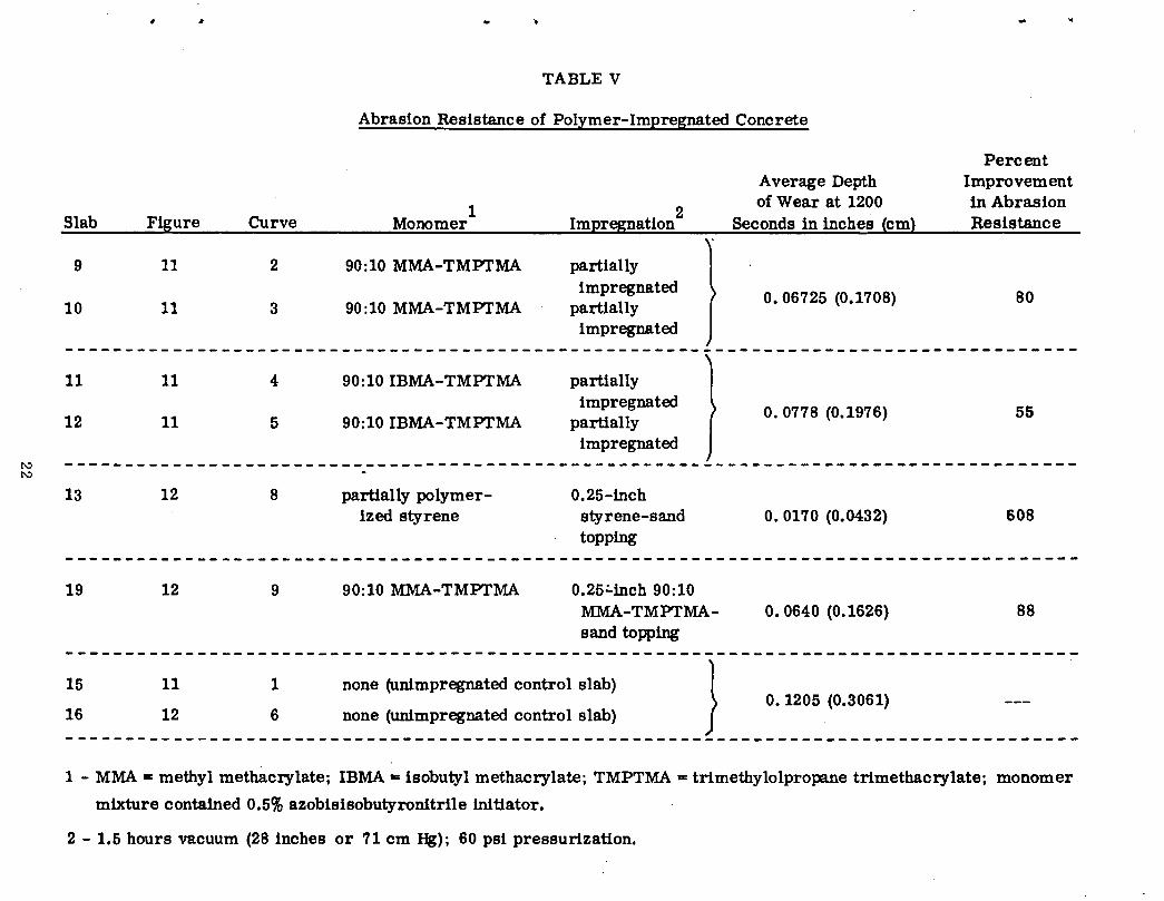
Slab Figure Curve
9 11 2
10 11 3
11 11 4
12 11 5
TABLE V
Abrasion Resistance of Polymer-Impregnated Concrete
1 Monomer
90:10 MMA-TMPTMA
90:10 MMA-TMPTMA
90:10 IBMA-TMPTMA
90:10 IBMA-TMPTMA
Impregnation 2
partially impregnated
partially impregnated
partially impregnated
partially impregnated
Average Depth of Wear at 1200
Seconds in inches (em)
o. 06725 (0.1708)
0. 0778 (0.1976)
Percent Improvement in Abrasion Resistance
80
55
~ ------------------------------------------------------------------------------------~
13 12 8
19 12 9
15 11 1
16 12 6
partially polymerized styrene
90:10 MMA-TMPTMA
0.25-inch styrene-sand topping
0.25.:..inch 90:10 MMA-TMPTMAsand topping
none (unimpregnated control slab)
J none (unimpregnated control slab)
0. 0170 (0.0432) 608
o. 0640 (0.1626) 88
o. 1205 (0.3061)
------------------------------------------------------------------------------------1 - MMA • methyl methacrylate; IBMA -= isobutyl methacrylate; TMPTMA = trimethylolpropane trimethacrylate; monomer
mixture contained 0.5% azobisisobutyronitrile initiator.
2 - 1.6 hours vacuum (28 inches or 71 em Hg); 60 psi pressurization.

..
..
Figure 1. Concrete slab mounted in oven for drying; weight loss measured by load cell
(not shown).
(f)
lfl6 g w 0::: ;::)
t;; 40 6 ::!:
24" x 24" x 6" Slob Spec. Oven Dried at 250°F
TIME IN HOURS
Figure 2. Typical dz:ying-rate curve for oven-drying of 24 x 24 x 6 inch (61 x 61 x 15 em)
thick concrete slab at 250°F (12rC).
23

.,
•
..
Figure 3. Propane torch assembly used in fast drying of concrete slabs and bridge deck.
--- ~
Monomer vesMI
24" zo•
zo•
.... ~~-==~~ . /~/ "' . // ,, I' \~ ,, I I II d I I IJ \\ 'I \\ I '' /I •'~ ~//.
'::::::::.--~~/
Figure 4. Conceptual representation of a pressure impregnation device.
24

j
•
..
Figure 5. Prototype pressure impregnation device bolted to concrete slab and mounted
on supports.
Figure 6. Fracture cross-section of first impregnated slab (lA) .showing polymer
impregnated and unimpregnated regions (note that fracture occurred through
the aggregate j>articles in the polymer-impregnated region and around the
particles in the unimpregnated region).
25

w ~ ~ 100 CJ)
>-c <{ w t- 75 CJ)
~ z 0 50 -~ a:: t-w z w 0..
~ 0
•
Slabs Cylinder Penetration l::P(K~:552 414 276 207 0 0 l:lP(psl) ·• 80 60 40 30 Opsl Opal (4• Bridge Core)
--lttft-~- --- 6" (I !5.24 em)
~I I I I I I I I I I I 4 11
( IOcm)
II; I ---
II I II I I
II I I 2"(5cm) --J/1 I Ill I ;I;
2 4 6 8 10 12
( Tl ME) ~~ hr. ~2
Figure 7. Variation of monomer penetration into a 6-inch (15-cm) concrete slab with time as a function of applied pressure: e cylinder; A slab (note for comparison, bridge deck core impregnated in the laboratory(13) at: E1 75 psi; X 0 psi.
\.D N

•
•
A B
Figure 8. Fracture cross-sections of cores from: A. salt-contaminated unimpregnated
concrete slab 5; B. polymer-impregnated concrete slab 2 (note uniform dark
coloration and difference of fracture mode of polymer-impregnated core) .
/
Figure 9. Scanning electron photomicrographs of the near-end sections of steel reinforcing
rods in salt-contaminated concrete slabs after freeze-thaw testing; A. polymer-
impregnated core 2-1; B. unimpregnated core 5-3.
27

•
•
BALL BlARING ABRASION TEST MACHINE
Figure 10 . Abrasion test apparatus.
~ ~ <I w ;!::
15 .... .... 0 0
:I: :I: ..... ..... <1- • (l_
10 ~ w 0
5
TIME IN SECONDS
Figure 11. Variation of depth of wear with time for polymer-impregnated and unimpreg
nated concrete slabs.
28

•
f'llrtiolly PolymeriMd Styrene Surfo<:e T reotmeot
Figure 12. Variation of depth of wear with time for polymer-impregnated, polymer-sand
topped, and unimpregnated concrete slabs.
2- 7 5- 3 1- 2 4- 7 5- 81 4-1 4- 91 2- 6
2- 7 5- 3 1- 2 4-7 5- 81 4-1
Figure 13. Sawed cross-sections of cores subjected to freeze-thaw testing: A. acid-etched;
B. polished (note virtually complete disintegration of cementitious matrix and
aggregate particles in unimpregnated cores).
29

,_
Figure 14. 4-inch (10-cm) core from polymer-impregnated bridge deck: A. acid-etched;
B. polished section (note limestone aggregate particles are eaten away, but
cementitious matrix is unaffected).
Water or Steam Supply
20' 20' 20'
Normal Traffic Flow
Normal Traffic Flow
lmpreQnotlon
Figure 15. Conceptual scale-up of pressure impregnation technique used here.
30