J Series Serial Commands Technical Reference - QED Productions
90
J Series Serial Commands Technical Reference Information 1 of 90 020-100796-01 Rev. 1 (10-2011) J Series Serial Commands Technical Reference Information INTRODUCTION This document describes the serial protocol, consisting of ASCII text messages, used to control an J Series projector remotely. CONNECTION AND USE: Once you have connected your computer to either the RS232 IN or RS422 IN port (depending on which standard is supported by your computer) or to the ETHERNET port on a projector, you can remotely access projector controls and image setups, issue commands or queries, and receive replies. Use these bi-directional messages to: • Control multiple projectors • Obtain a projector’s status report • Diagnose performance problems NOTES: 1) Refer to the User Manual provided with the projector for all cable requirements and other connection details. 2) Some commands are operational only when projector is powered up. UNDERSTANDING MESSAGE FORMAT Messages can be one of three types: • Set - A command to set a projector parameter at a specific level, such as changing to a certain channel. • Request - A request for information, such as what channel is currently in use. • Reply - The projector returns the data in response to a request or as confirmation of a command. All “remote control” information passes in and out of the projector as a simple text message consisting of a three letter command code, an optional four letter subcode and any related data. When a parameter for a specific source is being accessed, the four letter subcode will be added on to the command code. A number of optional features (message acknowledges, checksums, and network addressing) can be included. Generally, most commands include 0 or 1 data fields or parameters. Where applicable, a message may expand to include additional parameters of related details.
Transcript of J Series Serial Commands Technical Reference - QED Productions

J Series Serial CommandsTechnical Reference Information
INTRODUCTION
This document describes the serial protocol, consisting of ASCII text messages, used to control an J Series projector remotely. CONNECTION AND USE:Once you have connected your computer to either the RS232 IN or RS422 IN port (depending on which standard is supported by your computer) or to the ETHERNET port on a projector, you can remotely access projector controls and image setups, issue commands or queries, and receive replies. Use these bi-directional messages to: • Control multiple projectors • Obtain a projector’s status report • Diagnose performance problems NOTES: 1) Refer to the User Manual provided with the projector for all cable requirements and other connection details. 2) Some commands are operational only when projector is powered up.
UNDERSTANDING MESSAGE FORMAT
Messages can be one of three types:• Set - A command to set a projector parameter at a specific level, such as changing to a certain channel. • Request - A request for information, such as what channel is currently in use.• Reply - The projector returns the data in response to a request or as confirmation of a command.All “remote control” information passes in and out of the projector as a simple text message consisting of a three letter command code, an optional four letter subcode and any related data. When a parameter for a specific source is being accessed, the four letter subcode will be added on to the command code. A number of optional features (message acknowledges, checksums, and network addressing) can be included. Generally, most commands include 0 or 1 data fields or parameters. Where applicable, a message may expand to include additional parameters of related details.
J Series Serial Commands Technical Reference Information 1 of 90020-100796-01 Rev. 1 (10-2011)

The smallest step size for any parameter is always 1. For some controls (i.e. Size) the value displayed on the screen has a decimal point. (e.g. 0.200 to 4.000) In this case, the values used for the serial communications is an integer value (e.g. 200 to 4000), not the decimal value seen on the screen.Regardless of message type or origin, all messages use the same basic format and code. Opening and closing round brackets (parentheses) surround each message, see Table 1 - Message Formats. Table 1 - Message Formats
BASIC MESSAGE STRUCTURE
The following component fields comprise a standard ASCII message. Optional fields, such as extra characters for special modes, restrictions or added functionality, are shown in italics, with the exception of Notes. • START AND END OF MESSAGE: Every message begins with the left “(“character and ends with the
right “)“character. NOTE: If the start character is received before an end character of the previous message, the partial (previous) message is discarded.
• PREFIX CHARACTERS (OPTIONAL): For acknowledgement that the projector has responded, and/or to maximize message integrity, insert one or two special characters before the 3-character function code:
$ - Simple Acknowledgment, which will cause a ‘$’ character to be sent back from the projector when it has finished processing the message, see Maximizing Message Integrity. # - Full Acknowledgment, which will cause an echo of the message as a reply to be sent back from the projector when it has finished processing the message, see Maximizing Message Integrity.& - Checksum, which will allow a checksum to be put as the last parameter in the message for verification at the projector, see Maximizing Message Integrity.
• PROJECTOR NUMBERS (OPTIONAL): To control a selected projector or controller within a group, include its assigned number or address just before the three-character ASCII function code, see Network Operation.
• FUNCTION CODE: The projector function you wish to work with, such as channel selection or gamma, is represented by a three-character ASCII code (A-Z, upper or lower case). This function code appears immedi-ately after the leading “(“that starts the message. In messages sent to the projector that do not have a subcode, a space between the function code and the first parameter (or special character) is optional.
SOURCE MESSAGE FORMAT FUNCTION EXAMPLES
From Controller (Code Data) SET (set contrast of main image to 500)
(CON500) or (CON 500)
(Code+Subcode Data) SET (set contrast of PIP image to 500)
(CON+PIIP500) or (CON +PIIP 500)
From Controller (Code ?) REQUEST (what is current con-trast?)
(CON?) or (CON ?)
(Code+Subcode ?) REQUEST (what is contrast of PIP image?)
(CON+PIIP?) or (CON+PIIP ?)
From Projector (Code Data) REPLY (contrast is 500) (CON!500)
(Code+Subcode Data) REPLY (PIP contrast is 500) (CON+PIIP!500)
2 of 90 J Series Serial Commands Technical Reference Information020-100796-01 Rev. 1 (10-2011)

• +SUBCODE: The projector function you wish to work with may have one or more subcodes that will allow you to select a specific source, image, channel or subfunction. The subcode is represented by a four-character ASCII code (A-Z, upper or lower case, and 0-9). This subcode appears immediately after the function code, with a “+” character to separate the code and subcode. If there is no subcode, the “+” is also omitted. In mes-sages sent to the projector that do have a subcode, a space between the subcode and the first parameter (or special character) is optional.
• REQUEST/REPLY SYMBOLS: If the controller is requesting information from the projector, a “?” ques-tion mark appears directly after the function code. If the projector is replying, a “!” exclamation mark appears directly after the function code. For set messages to the projector, neither of these characters appear — data directly follows the code and subcode.
• OTHER SPECIAL FUNCTIONS (OPTIONAL): To add functionality to the current message, include one or more of the following special characters between the function code/subcode and the first parameter. If more than one, add them in any order, see Flow Control .
C Control Class InquiryD Default value/TextE Enable Control Inquiry. G Access Group Inquiry. H Return the Help text for a control. L Return a list of options for ‘list’ controls. M Find min/max adjustments (i.e., range). N Return the name of the control. T Return the type of control (i.e. Slidebar etc.).
• DATA: The value for a given projector state, such as “on” or “off”, appears in ASCII-decimal format directly after the request/reply symbol. You can add an optional space after the symbol—i.e., before the data—in a set message, but data in replies follow the “!” symbol without a space. Other details to remember about data:
• All values returned by the projector (reply messages) have a fixed length, regardless of the actual value. For a specific parameter the length will always be the same (e.g. contrast is always returned as 3 charac-ters, projector number is always returned as 5 characters). The minimum parameter size is 3 characters. Values that are less than the predefined size will be padded with leading zeros as needed. Parameters which have negative signs are zero padded after the negative sign, and will have one less digit to make space for the sign.
• If entering a negative number, there must be a space between the code/subcode and the value e.g. (CRM3) and (CRM 3) can both be used when the number is positive. (CRM -2) is acceptable, but (CRM-2) is not.
• Data in set messages to the projector do not require padding with zeros. • Within each message, multiple parameters of data must be separated by one “space” character. • Text parameters such as channel names are enclosed in double quotes following the data, as in “Name”.
• TEXT PARAMETERS: Most data is simply a numerical value, however some messages also require text. For example, a channel naming message typically includes a text-based name - enclose this text in double quotation marks, as in “Tilt the Wagon”. Use all characters as desired except for the following special char-acters shown in the left column below—these require a 2-character combination, see Table 2 - Special Char-acters for Text.
J Series Serial Commands Technical Reference Information 3 of 90020-100796-01 Rev. 1 (10-2011)

Table 2 - Special Characters for Text
SAMPLE MESSAGES AND THEIR MEANING
Table 3 - Sample Messages and Their Meaning
If you want this... Enter this... Description
\ \\ Backslash
” \” Quote
( \( Left Bracket
) \) Right Bracket
0x0A \n New line - if the text can be displayed on more than one line, this will set the line break.
\h## Sends one arbitrary code defined by the 2 hexadecimal digits ##
For a Single Projector
Message Format Function Example
(Code Data) SET (set contrast of main image to 500) (CON500)
(Code+Subcode Data) SET (set contrast of PIP image to 500) (CON+PIIP500)
(Code?) REQUEST (what is current contrast?) (CON?)
(Code+Subcode?) REQUEST (what is contrast of PIP image?) (CON+PIIP?)
(Code!Data) REPLY (contrast is 64) (CON!64)
(Code+Subcode!Data) REPLY (PIP contrast is 64) (CON+PIIP!64)
($Code Data) SET AND ACKNOWLEDGE MESSAGE (mes-sage processed?)
($CON64)
(&Code+Subcode Data Checksum) SET WITH CHECKSUM (&CON64 240)
For a Specific Projector within a Network with 1 Controller present
Message Format Function Example
(Dest Addr Code Data) SET (turn projector #5 on) (5pwr1)
($Dest Addr Code Data) SET AND ACKNOWLEDGE MESSAGE (message processed?ffr55)
($5pwr1)
For a Specific Projector within a Network with Multiple Controllers present
Message Format Function Example
(Dest Addr Src Code?) REQUEST (get contrast from projector #5 to controller #2)
(5 2con?)
4 of 90 J Series Serial Commands Technical Reference Information020-100796-01 Rev. 1 (10-2011)

WHAT IS ACTUALLY SENT IN A MESSAGE
Although you will send and read messages as strings of ASCII characters, the actual message travels as a sequence of bytes. Each character in this sequence requires 1 byte. See example below, which illustrates a “lamp limit is 2000 hours” reply from the projector.
MAXIMIZING MESSAGE INTEGRITY
For additional reassurance and/or maximum message integrity, you can insert one or two special characters:ACKNOWLEDGMENTS: If you want assurance from the projector (or group of projectors) that a set message has been processed, request an acknowledgement. The acknowledgement is returned after the message has been received and fully executed by the projector (i.e. in the case of a source switch it is not sent until the switch is complete). If the message is not able to execute for some reason (i.e. invalid parameters, time-out, etc) a NAK is returned instead (not-acknowledge). Note that requesting an acknowledgement serves no purpose when included in a request message, since the acknowledgement will be redundant to the actual reply from the projector. However, if requested, the “$” acknowledgement from the projector will follow the reply.
There are two types of acknowledgements:• SIMPLE ACKNOWLEDGEMENTS: Insert a “$” character just after the start code “(“. This will only
return a ‘$’. This will only return a '$' on success, or a '^' on failure (NAK).• FULL ACKNOWLEDGEMENTS: Insert a “#” character just after the start code “(“. This will return
the message sent, as a reply.This is a quick way to confirm success with set messages, and is particularly useful with long-distance communication links or where the projectors and/or images are not visible from the controller. Acknowledge-ments can also be a type of flow control.
For a Specific Projector within a Network with Multiple Controllers present
Message Format Function Example
($Dest Addr Src Code Data) SET AND ACKNOWLEDGE MESSAGE (is message from controller #2 processed by pro-jector #5)
($5 2con?)
(Dest Addr Src Code!Data) REPLY (from projector #5 to controller #2: contrast is 64)
(002 005con!064)
ASCII = ( L P L ! 2 0 0 0 )
HEX = 0x28 0x4 0x50 0x28 0x21 0x32 0x30 0x30 0x30 0x29
J Series Serial Commands Technical Reference Information 5 of 90020-100796-01 Rev. 1 (10-2011)

• CHECKSUMS: For maximum message integrity, add a checksum character “&” just after the start code “(“. You must then also include the correct checksum total (0-255) just before the “)” end code. Make sure to add a space before the calculated checksum to separate it from the last data parameter:
The checksum is the low byte of the sum of the ASCII values of all characters between the “(“and the beginning of the checksum, but not including either. It does include the space in front of the checksum. Calculate the checksum for the above “set contrast to 64” command as follows: CHECKSUM EXAMPLE = & + c + o + n + 6 + 4 + ‘space’ = 26h+63h +6Fh +6E h +36h +$34h +$20h = 01F0h= F0h when only the low byte is used = 240The projector collects all of the message bytes as defined in the first byte of the message, then creates its own checksum value for comparison with the checksum included in the controller’s message. If the values match, the message is considered to have been correctly received—otherwise the message is discarded. NOTES: 1) ‘h’ indicates a hex number. 2) If a “request” message has a checksum so will the reply. 3) If using both “acknowledge” and “checksum”, either character can occur first.
MESSAGE ERRORS
If a command cannot be performed (e.g. syntax error), you will receive a descriptive error indicating the problem. For example: (ITP)(65535 00000 ERR00005 "ITP: Too Few Parameters")For more examples of a descriptive error, see Table 4 - Descriptive Error.Table 4 - Descriptive Error
Error Code Error Description Error Code Error Description
3 "Invalid Parameter" 107 "Exceeded List Size"
4 "Too Many Parameters" 108 "Exceeded Text Size"
5 "Too Few Parameters" 109 "Invalid Pointer"
6 "Channel not found" 110 "Communication Timeout"
7 "Command not executed" 111 "Communications Failure"
8 "Checksum error" 112 "Failed to set Hardware"
9 "Unknown request" 113 "Bad File"
10 "Error receiving serial data" 114 "Memory Failure"
101 "Control Not Found" 115 "Not Implemented"
102 "Subcontrol Not Found" 116 "Invalid Security Token"
103 "Wrong Control Type" 117 "Invalid Access Group"
104 "Invalid Value" 118 "System Busy - Try Again Later"
105 "Disabled Control" ?? "Unknown Error"
106 "Invalid Language"
6 of 90 J Series Serial Commands Technical Reference Information020-100796-01 Rev. 1 (10-2011)

ACCESSING SPECIFIC CHANNELS OR INPUTS
For several commands (for example, ASR, Auto Channel Select) you can direct the message to particular channel, input or image. To do this, include a subcode after the function code. Example:
(ASR 1)Enable Auto Channel Select for the channel being used by the Main image(ASR+MAIN 1)Enable Auto Channel Select for the channel being used by the Main image(ASR+PIIP 1)Enable Auto Channel Select for the channel being used by the PIP image(ASR+SECD 1)Enable Auto Channel Select for the channel being used by the Secondary image(ASR+C003 1)Enable Auto Channel Select for channel 3(BBL+IN12 30)Set the bottom blanking value on slot 1 input 2 to value 30
It is only possible to set parameters from a specific channel or input if that parameter is stored separately for each channel or input. This function cannot be used for parameters that are specified for the projector as a whole such as projector address. The serial commands listed in the document specify which subcodes are applicable to each function.The PIP and Secondary images both refer to the image on the secondary image path. Depending on your projector model type, either PIP or secondary commands will be applicable to this image. However, for serial commands, PIIP and SECD can be used interchangeably as shown within this document.
FLOW CONTROL
Normally messages can be sent to the projector before processing of earlier messages is complete—the projector will just store messages in a buffer until ready to process. However, if a series of messages is sent it is possible that the projector may not be able to process them as fast as they arrive and the buffer will become full. If this happens, the projector will send the 13h (Xoff) code to instruct the controller (or any devices preparing to transmit) to cease transmission. At this point, the controller must respond immediately and send no more than 10 extra characters or they may be lost (i.e., the projector is able to accommodate the receipt of up to 10 more bytes after it sends 13h (Xoff)). When the buffer is once again available, the projector will send a 11h (Xon) command to resume transmission. NOTE: Xon and Xoff controls apply to both directions of communication. The projector will not send more than 3 characters after it has received a 13h (Xoff) code.
NETWORK OPERATION
Up to 1000 projectors can be linked together in a chain with the ‘OUT’ port on one connected to the ‘IN’ port on the next. A controller connected to the ‘IN’ port on the first projector can control them all, either by broadcasting messages which have no address and are thus seen by all projectors, or by directing messages to specific projector addresses. To work with a specific projector in a group, the projectors must first be assigned a unique I.D.—either a projector number or an Ethernet IP address. Insert the number of the target projector between the starting ‘(’ and the 3-character ASCII code.
J Series Serial Commands Technical Reference Information 7 of 90020-100796-01 Rev. 1 (10-2011)

Table 5 - Message for Specific Projector
Each projector compares the message address with its own address and, if matching, responds and processes the message. If the address does not match, the message is passed on until it reaches the intended projector. Although messages without an address are always broadcast, you can also broadcast by including the reply destination address 65535. This ensures that replies go to a specific controller address rather than being broadcast. The projector will also include its address. Table 6 - Message for Projector from a Specific Controller
If you have more than one controller on a network, ensure to include both a source address and a destination address. With a single controller on the network, its address is never required. Place the source address between the destination address and 3-character code, including a space before and after as shown. NOTE: Replies from a projector do not contain an address unless the request message includes both a destination address and a source address—i.e., a reply to a request having only a destination address will not have any source address.
Table 7 - Message for Specific Projector from a Specific Controller
( Addr Code Data )
( Dest Src Code Data )
( Dest Src Code Data )
Examples
Command Message from Controller Reply from Projector
Turn Projector #5 on. (5pwr1) {none}
What is the contrast level in Projector 30? (30con?) (CON!127)
Return Contrast from Projector #30 to Controller #2. (30 2con?) (00002 00030con!127)
8 of 90 J Series Serial Commands Technical Reference Information020-100796-01 Rev. 1 (10-2011)

DESCRIPTION OF CONTROL TYPES
SUBCLASSES
• Power Down Controls - These controls are accessible when the projector is in Standby power mode (i.e. power off) as well as when powered on.
• Power Up Controls - These controls are only accessible when the system electronics are fully powered (not necessarily lamp on).
CONTROL GROUPS
• Unsaved Controls - These controls are not saved to flash. The settings are not maintained between power sessions.
• Saved Controls - These controls are saved to flash. The settings are persistent between power sessions.
• Preference Controls - These controls are transferable from one projector to another. Example: NET+SUB0 (projector subnet).
• Configuration Controls - These controls are projector specific settings. They are non-transferable between projectors. Example: NET+ETH0 (projector IP address).
• Channel Controls - These settings are specific to a particular input signal. Example: BRT (signal bright-ness).
• Option Card Controls - These settings are specific to a particular option card type / slot combination.
ACCESS LEVELS
• Operator - Command is available at the operator level log in.
• Advanced - Command is available at the advanced operator level log in.
• Admin - Command is available at the administrator level log in.
• Service - Command is available at the service level log in.
J Series Serial Commands Technical Reference Information 9 of 90020-100796-01 Rev. 1 (10-2011)

SUMMARY LIST OF SERIAL COMMANDS
(ACE) Auto Color Enable (BRT) Brightness (FAS) Fan Assist Switch
(ACO) Adaptive Contrast (BRU) Brightness Uniformity (FCS) Focus Lens Position Adjust-ment
(ACT) Active Window (CCD) Output Color Default (FIL) Filter
(ADR) Address (CCI) Interpolated Color (FLE) Frame Lock Enable
(AGC) Automatic Gain Control (CCS) Select Output Color (FLW) Serial Flow Control
(AIC) Auto Input Cycling (CHA) Channel (FMD) Film Mode Detect
(AIL) Auto Input Level (CLE) Color Enable (FRD) Frame Delay
(ALT) Active Loop-Through (CLP) Clamping (FRF) Free Run Frequency
(APJ) Active Projector (CLR) Color (FRZ) Freeze Image
(APR) Aperture (CON) Contrast (FTB) Fade to Black
(APW) Auto Power Up (CRM) Chroma/Luma Delay (GAM) Gamma Correction
(ARO) Aspect Ratio Overlay (CSP) Color Space (GIA) Analog BNC Grounded Input Selection
(ASH) Auto Shutdown (DED) Dual DVI EDID Type Selection
(GID) Video Decoder Grounded Input Selection
(ASR) Auto Channel Select (DEF) Defaults (GIO) General Purpose Input/Output
(ASU) Auto Setup (DLG) Data Logging (GMS) VDIC Grouped-Inputs Mode
(BBL) Bottom Blanking (DMX) DMX/ArtNet (GNB) Green Black Level
(BDR) Baud Rate (DRK) 3D Dark interval (GND) Green Drive
(BGC) Base Gamma Curve (DTL) Detail (GOG) Green Odd Pixel Gain
(BGF) Base Gamma Function (DTO) Detail Overshoot (GOO) Green Odd Pixel Offset
(BGS) Base Gamma Slope (DTT) Detail Threshold (HDC) DHDIC Dual-Link Configu-ration
(BKY) Broadcast Key Mode (EBB) Blacklevel Blending (HIS) Lamp History
(BLB) Blue Black Level (EBL) Edge Blending (HLP) Serial Help
(BLD) Blue Drive (EME) Error Message Enable (HLT) Projector Health
(BOG) Blue Odd Pixel Gain (ESC) Edit Secondary Channel Set-ting
(HOR) Horizontal Position
(BOO) Blue Odd Pixel Offset (FAD) Fade Time (ILS) Intelligent Lens System
10 of 90 J Series Serial Commands Technical Reference Information020-100796-01 Rev. 1 (10-2011)

(ILV) ILS Settings Valid (MDE) Serial Mode (PMT) Picture Mute
(INM) Channel ‘In Menu’ (MFT) Menu Font (PNG) Ping
(ITG) Test Pattern Grey (MLK) Channel Memory Lock (PPA) Position Preset Aspect
(ITP) Internal Test Pattern (MNR) Mosquito Noise Reduction (PPP) PIP Position Preset
(KEN) Keypad IR Sensor Disable (MNU) Menu Settings and Config-uration
(PPS) PIP Swap
(KEY) Key Mode Emulation (MSH) Menu Shift Horizontal (PRT) Serial Port
(LBL) Left Blanking (MSP) Menu Location (PTL) Serial Protocol
(LCB) Lens System Calibration (MSV) Menu Shift Vertical (PVP) PIP Vertical Position
(LCD) LCD Backlight (NAM) Channel Name (PWR) Power
(LDT) Level Detector (NET) Network Setup (PXP) Pixel Phase
(LDV) Level Detector Value (NRB) Block Artifact Reduction (PXT) Pixel Tracking
(LHO) Lens Horizontal Position Adjustment
(NRD) General Noise Reduction (RAL) Remote Access Level
(LLC) LiteLoc Calibration (NTR) Network Routing (RBL) Right Blanking
(LMV) Adjust Lens Position/Lens Move
(OPP) Odd Pixel Phase (RDB) Red Black Level
(LOC) Local Settings (OSD) On Screen Display (RDD) Red Drive
(OST) OSD Transparency (ROG) Red Odd Pixel Gain
(LOS) Loop Out Source Selection (PBC) PIP Border Color (ROO) Red Odd Pixel Offset
(LPI) Lamp Intensity (PBW) PIP Border Width (RQR) RGB Quantization Range
(LPL) Lamp Life (PDT) Peak Detector (RTE) Real Time Events
(LPM) Lamp Mode (PHP) PIP Horizontal Position (SHU) Shutter
(LPP) Lamp Power (PHS) PIP Horizontal Size (SIN) Select Input
(LVO) Lens Vertical Offset Posi-tion Adjustment
(PIP) Picture In Picture (SIZ) Size
(MBE) Message Box Enable (PJH) Projector Hours (SMP) Sampling Mode
(MCS) Menu Cascading Enable (PLK) User Lockouts (SOR) Screen Orientation
J Series Serial Commands Technical Reference Information 11 of 90020-100796-01 Rev. 1 (10-2011)

(SPS) Splash Screen (TDM) 3D Mode (TTM) THIC Transmitter Mode Configuration
(SPT) Split Screen (TDN) Invert 3D Input (TXE) Texture Enhancement
(SST) System Status (TDO) 3D Sync Out (UID) User ID
(STD) Video Standard (TDT) 3D Test Pattern (VBL) Video Black Input
(SZP) Size Presets (TED) Twin HDMI EDID type selection
(VRT) Vertical Position
(TBL) Top Blanking (TIL) Tiling Control (VST) Vertical Stretch
(TDD) 3D Emitter Delay (TMD) Time/Date (WRP) Warp / Keystone
(TDI) 3D Sync Input (TNT) Tint (ZOM) Lens Zoom Position Adjust-ment
12 of 90 J Series Serial Commands Technical Reference Information020-100796-01 Rev. 1 (10-2011)

DETAILED SERIAL COMMAND DESCRIPTIONS
(ACE) AUTO COLOR ENABLE
CONTROL GROUP: Preference SUBCLASS: Power Up ACCESS LEVEL: Operator
DESCRIPTIONAutomatically select Color Enable based on the control being adjusted. If enabled, this control allows the projec-tor to automatically change the color enable control when the user is using the OSD interface to adjust controls such as input levels, odd pixel, and brightness uniformity. This is an unsaved control, which can only be set when powered on, and only affects the operation of the On Screen Menus.
SUBCODE<No Subcode>
DESCRIPTION OF USEEnable/Disable auto color controls.
EXAMPLES:(ACE 0) - Disable Auto Color (ACE 1) - Enable Auto Color
(ACO) ADAPTIVE CONTRAST
CONTROL GROUP: Input SUBCLASS: Power Up ACCESS LEVEL: Operator
DESCRIPTIONAdaptive Contrast Enhancement dynamically expands the contrast of the output image producing vibrant images with seamless response to scene changes and fades. The adaptive contrast function implements a dynamic non-linear mapping between the input and output contrast levels based on frame-by-frame luminance histogram mea-surement of the input image.
SUBCODEINxy
DESCRIPTION OF USESet the adaptive contrast for slot x, input y. Range 0-15.
MAIN Set the adaptive contrast for main video. Range 0-15.
PIIP or SECD Set the adaptive contrast for PIP or Secondary video. Range 0-15.
EXAMPLE:(ACO 8) - Set adaptive contrast for main image to 50% strength.
(ACT) ACTIVE WINDOW
CONTROL GROUP: Input SUBCLASS: Power Up ACCESS LEVEL: Operator (Read Only)
DESCRIPTIONThis control defines the input active window in pixels. The production aperture is available for analog sources only, but not for decoded analog signals. The aperture is set once on every auto setup or on new signal detection when a channel for that signal is not present. The aperture defines the maximum window in which blanking con-trols can be opened up to, relative to the active portion of the signal. This is a read only control.
SUBCODEINxy
DESCRIPTION OF USESet the adaptive contrast for slot x, input y.
MAIN Set the adaptive contrast for main video.
PIIP or SECD Set the adaptive contrast for PIP or Secondary video.
J Series Serial Commands Technical Reference Information 13 of 90020-100796-01 Rev. 1 (10-2011)

(ACT) Active Window con’t
EXAMPLES:(ACT?) - Returns the active window for main video. (ACT+PIIP?) - Returns the active window for PIP video. (ACT+IN12?) - Returns the active window for slot 1 input 2.
(ADR) ADDRESS
CONTROL GROUP: Preference SUBCLASS: Power Down ACCESS LEVEL: Operator
DESCRIPTIONSet/Query Device Address on ASCII Protocol network. Required only for RS232 connections that are daisy chained to allow directed messages.
SUBCODE<No Subcode>
DESCRIPTION OF USEValid Address range is 0 to 999. Reserved broadcast address is 65535.
EXAMPLES:(65535 ADR 0) - Set all devices to address 0. (0 ADR 5) - Set first device at address 0 to address to 5. (65535 1001ADR?) - Query address for all devices and return results to address 1001. Expected response to previous query (01001 00005ADR!005).
(AGC) AUTOMATIC GAIN CONTROL
CONTROL GROUP: Input SUBCLASS: Power Up ACCESS LEVEL: Operator
DESCRIPTIONEnable/disable the Automatic Gain Control. This control allows the decoder to automatically track the sync amplitude of the incoming signal. Turn this control off if you are experiencing strange color artifacts, indicating an incompatibility between the source and the AGC.
SUBCODEINxy
DESCRIPTION OF USESet the AGC on slot x, input y to the specified state of either enable or disable.
MAIN Set automatic gain control on main image.
PIIP or SECD Set automatic gain control on PIP or Secondary image.
EXAMPLES:(AGC 1) - Enable AGC on main video. (AGC+MAIN 0) - Disable AGC on main video. (AGC+PIIP 1) - Enable on PIP video. (AGC?) - Returns the current AGC state on main video. (AGC+PIIP ?) - Returns the current AGC state on PIP video. (AGC+IN12 ?) - Returns the current AGC state on slot 1 input 2.
14 of 90 J Series Serial Commands Technical Reference Information020-100796-01 Rev. 1 (10-2011)

(AIC) AUTO INPUT CYCLING
CONTROL GROUP: Preference SUBCLASS: Power Down ACCESS LEVEL: Operator
DESCRIPTIONWhen enabled, the system will continually search for the next valid signal when no signal is present or when loss of sync occurs on the current user selected input. In the case of multiple signals to choose from, the order is based on slot, followed by inputs on that slot.
SUBCODE<No Subcode>
DESCRIPTION OF USEEnable or disable auto input cycling.
EXAMPLES:(AIC 0) - Disable auto input cycling. (AIC 1) - Enable auto input cycling.
(AIL) AUTO INPUT LEVEL
CONTROL GROUP: Unsaved SUBCLASS: Power Up ACCESS LEVEL: Operator
DESCRIPTIONIf enabled, this control allows the projector to continuously monitor the input signal levels of the analog inputs and make adjustments as needed. Whenever the projector detects a level that would lead to the crushing of black or white levels, it adjusts the input offset or gain to compensate. If the input signal is not being crushed, the pro-jector will do nothing. The Auto Input Level feature should only be used when the current source requires further input level adjustment. There must be at least 12 consecutive white pixels in the image in order to use Auto Input Levels. The monitor period will run for 10 seconds after being issued. Auto setup or source switching will stop the level period. To use this control, turn it on, wait for the blacklevel and drive values to stabilize, and turn it off or wait for the 10 seconds. When Auto Input level is turned off, the current drive and blacklevel values are main-tained. This control only applies to analog BNC or Dual DVI cards.
SUBCODEMAIN
DESCRIPTION OF USEPerform auto input level on the main image.
PIIP or SECD Perform auto input level on PIP or Secondary image.
EXAMPLES:(AIL 1) - Perform auto input level on the main image. (AIL+PIIP 1) - Perform auto input level on the PIP image.
(ALT) ACTIVE LOOP-THROUGH
CONTROL GROUP: Preference SUBCLASS: Power Down ACCESS LEVEL: Operator
DESCRIPTIONIn situations where a Twin HDMI Input card is being used to loop signals out to another projector, this feature ensures that video signals continue to be looped out when the projector enters Standby power mode. Note that when the projector is in Standby mode (and this feature is enabled), limited channel control is available - inputs can be switched, can perform Auto Setup and some limited input settings can be modified.
SUBCODE<No Subcode>
DESCRIPTION OF USEEnable or disable active loop-through.
J Series Serial Commands Technical Reference Information 15 of 90020-100796-01 Rev. 1 (10-2011)

(ALT) Active Loop-Through con’t
EXAMPLES:(ALT 1) - Enable Standby active loop-through. (ALT 0) - Disable Standby active loop-through.(ALT?) - Get the current Standby active loop-through setting.
(APR) APERTURE
CONTROL GROUP: Preference SUBCLASS: Power Up ACCESS LEVEL: Operator
DESCRIPTIONThe Optical Aperture control sets the diameter of the light path. It is used to trade off between contrast and bright-ness. Larger values increase contrast and decrease brightness. This is done in the optical path rather than electron-ically which is how the Contrast and Brightness controls function.
SUBCODE<No Subcode>
DESCRIPTION OF USESet aperture open/close.
EXAMPLES:(APR 0) - Set aperture to full open. (APR 17) - Set aperture to full close.
(APJ) ACTIVE PROJECTOR
CONTROL GROUP: Unsaved SUBCLASS: Power Down ACCESS LEVEL: Operator
DESCRIPTIONTemporarily enable or disable the IR and wired keypad inputs to a specific projector in a network of projectors. When a projector is disabled, the only key that works is PROJ. The next time the projector is powered up again, it will revert to fully enabled. The built-in keypad will always be fully functional. This control does not overwrite the Front IR, Back IR and Wired Keypad settings.
SUBCODE<No Subcode>
DESCRIPTION OF USEEnable or disable IR remote control access to the projector.
EXAMPLES:(APJ 1) - Projector is active (IR remote control access is enabled). (APJ 0) - Projector is not active (IR remote control access is temporarily disabled). (APJ?) - Is the IR remote control access is active or not.
(APW) AUTO POWER UP
CONTROL GROUP: Preference SUBCLASS: Power Down ACCESS LEVEL: Operator
DESCRIPTIONWhen the A/C switch is turned on, the projector will automatically change from Stand-by Mode to Power On Mode, if there has been an AC interruption in the previous power cycle.
SUBCODE<No Subcode>
DESCRIPTION OF USEEnable or disable auto power up.
16 of 90 J Series Serial Commands Technical Reference Information020-100796-01 Rev. 1 (10-2011)

(APW) Auto Power Up con’t
EXAMPLES:(APW 0) - Projector will remain in Standby Mode until the user presses the power key. (APW 1) - Projector will auto power up when A/C power is switched on if it was in a powered on state (i.e. not in standby mode) when the A/C power was powered off in the previous power cycle.
(ARO) ASPECT RATIO OVERLAY
CONTROL GROUP: Unsaved SUBCLASS: Power Up ACCESS LEVEL: Operator
DESCRIPTIONEnables or disables Aspect Ratio layer over Image layer.
SUBCODE<No Subcode>
DESCRIPTION OF USEEnable or disable aspect ratio overlay.
EXAMPLES:(ARO 1) - Turn on Aspect Ratio Overlay. (ARO 0) - Turn off Aspect Ratio Overlay.
(ASH) AUTO SHUTDOWN
CONTROL GROUP: Saved SUBCLASS: Power Down ACCESS LEVEL: Operator
DESCRIPTIONWhen Auto Shutdown Mode has been selected, and no projector activity has been seen for the activation time-out period, the projector will enter a power saving mode in which the lamps will dim and the shutter close. If this con-dition persists for an additional time-out period the projector will automatically go to standby. The presence of any activity within this is combined interval will cancel Auto Shutdown and return the projector to normal opera-tion.
SUBCODE<No Subcode>
DESCRIPTION OF USEEnable or disable Auto Shutdown Operation.
SBTO Set the uninterrupted time-out period that must elapse before pro-jector will enter Standby Mode (The second time-out period or Standby time-out).
ALTO Set the uninterrupted time-out period that must elapse time of activity loss until Auto Shutdown is activated (The first time-out period or Activation time-out).
EXAMPLES:(ASH 1) - Turn on Auto Shutdown Mode. (ASH 0) - Turn off Auto Shutdown Mode.(ASH+SBTO 10) - Set standby time-out to 10 minutes.(ASH+ALTO 10) - Set source activity loss time-out to 10 minutes.
J Series Serial Commands Technical Reference Information 17 of 90020-100796-01 Rev. 1 (10-2011)

(ASR) AUTO CHANNEL SELECT
CONTROL GROUP: Channel SUBCLASS: Power Up ACCESS LEVEL: Operator
DESCRIPTIONThe Auto Channel Select option allows the projector to select the channel memory best suited to the input signal. If the current channel does not allow Auto Channel Select, the projector will not attempt to select a new channel when the signal changes. If the current channel does allow Auto Channel Select, then upon signal detection, an existing channel will be chosen. If a match is not found a new channel will be created.
SUBCODEC0xx
DESCRIPTION OF USEEnable/disable Auto Channel Select on channel (xx=channel num-ber from 01 to 99).
MAIN Enable/disable Auto Channel Select on the channel being used by main.
PIIP or SECD Enable/disable Auto Channel Select on the channel being used by PIP or Secondary.
EXAMPLES:(ASR?) - Get Auto Channel Select state for channel being used by main. (ASR+MAIN?) - Get Auto Channel Select state for channel being used by main. (ASR+PIIP?) - Get Auto Channel Select state for channel being used by PIP. (ASR 1) - Enable Auto Channel Select for the channel being used by main. (ASR+PIIP 1) - Enable Auto Channel Select for the channel being used by PIP. (ASR+MAIN 0) - Disable Auto Channel Select for the channel being used by main. (ASR+C001 0) - Disable Auto Channel Select for channel 1.
(ASU) AUTO SETUP
CONTROL GROUP: Unsaved SUBCLASS: Power Up ACCESS LEVEL: Operator
DESCRIPTIONThis control tells the projector to automatically adjust as many parameters as it can to produce the optimal setup for the current input. NOTE: If main and PIP/Secondary video are using the same channel, the auto setup will act on both, regardless of the sub-code being used. In some cases for analog video, the user can select the format that best suits their source. This selection helps the auto setup get the correct settings for the tracking and phase controls for analog sources that contain the same number of active lines, but have a different aspect ratios. - All digital and decoder option cards do not allow options for auto setup since digital hardware provides enough information to perform the correct auto setup.- Analog PC graphics sources (4/5-wire sync) present a list of formats based on the current active lines detected in the video.- Analog Video Sources (3 wire sync on green) always have the options ‘standard’ and ‘advanced’. Video sources use a look up table to determine their format based on video standards. The ‘advanced’ auto setup selection mea-sures the start pixel and start line whereas ‘standard’ uses the table values as is.
SUBCODEMAIN
DESCRIPTION OF USEPerform a standard auto setup on the main video.
18 of 90 J Series Serial Commands Technical Reference Information020-100796-01 Rev. 1 (10-2011)

(ASU) Auto Setup con’t
PIIP or SECD Perform a standard auto setup on the picture in picture or Second-ary video.
FRZE Hides temporary image artifacts that may appear during the auto setup procedure.
EXAMPLES:(ASU) - Perform standard auto setup on main video. (ASU+FRZE 1) - Freeze image during auto setup.(ASU+FRZE 0) - Disable image freezing during auto setup.(ASU+MAIN) - Perform standard auto setup on main video. (ASU+PIIP) - Perform standard auto setup on PIP.
(BBL) BOTTOM BLANKING
CONTROL GROUP: Input SUBCLASS: Power Up ACCESS LEVEL: Operator
DESCRIPTIONSet the number of lines to blank (turn to black) at the bottom of the image. This can be used to blank out any unwanted data near the bottom edge of the image. A positive amount of blanking makes the image smaller. A negative amount of blanking makes the image larger. Negative blanking is only applicable to analog signals, when the autosetup has not been able to set the image size correctly. It is preferable not to use negative blanking, but to run autosetup again, ensuring that the content has active pixels on each edge of the image. The maximum amount of bottom blanking allowed is half the image height minus 10. For negative blanking, the image size can only be increased to the limit of the sync.
SUBCODEINxy
DESCRIPTION OF USESet the bottom blanking for slot x, input y.
MAIN Set the bottom blanking for the main image.
PIIP or SECD Set the bottom blanking for the PIP or Secondary image.
EXAMPLES:(BBL 40) - Set bottom blanking to 40 on main video. (BBL+MAIN 40) - Set bottom blanking to 40 on main video. (BBL+PIIP 40) - Set bottom blanking to 40 on PIP video. (BBL+IN32 40) - Set bottom blanking to 40 on slot 3 input 2. (BBL?) - Returns the bottom blanking value on main video. (BBL+PIIP?) - Returns the bottom blanking value on PIP video. (BBL+IN12?) - Returns the bottom blanking value on slot 1 input 2.
J Series Serial Commands Technical Reference Information 19 of 90020-100796-01 Rev. 1 (10-2011)

(BDR) BAUD RATE
CONTROL GROUP: Preference SUBCLASS: Power Down ACCESS LEVEL: Advanced
DESCRIPTIONSet the baud rate for a serial communications port. For RS232 IN and RS232 OUT, the default is 115200. For RS422, the default is 19200. The default communications settings for all ports is 8 data bits, no parity. Valid baud rates, with the values to select them, are: 0 = 1200 1 = 2400 2 = 9600 3 = 19200 4 = 38400 5 = 57600 6 = 115200
SUBCODEPRTA
DESCRIPTION OF USESet the baud rate on port A (RS232 IN).
PRTB Set the baud rate on port B (RS232 OUT).
PRTC Set the baud rate on port C (RS422).
EXAMPLES:(BDR+PRTA 6) - Set baud rate on port A to 115200 bits per second. (BDR+PRTA?) - Get baud rate (BRD+PRTA!"115200").
(BGC) BASE GAMMA CURVE
CONTROL GROUP: Input SUBCLASS: Power Up ACCESS LEVEL: Operator
DESCRIPTIONThis control lets you select the gamma table. You can select from one of the standard tables, or select an arbitrary gamma table that has been downloaded into the projector. A separate PC utility is needed to do this. The 2.22 table is a simple power curve. The standard table is a modified 2.22 curve with an optimized linear portion in the low end of the curve. This is the same as selecting a custom table and setting the function to be 2.22 and the slope to be 1.0. Selecting Gamma Function from the drop down list enables the Gamma Function and Gamma Slope controls.Valid values are: 0 = Standard 1 = 2.22 2 = Gamma Function
SUBCODEINxy
DESCRIPTION OF USESet the base gamma curve for slot x, input y.
MAIN Set the base gamma curve for main video.
PIIP or SECD Set the base gamma curve for PIP or Secondary video.
EXAMPLES:(BGC 0) - Set main video to the standard base gamma table. (BGC+MAIN 0) - Set main video to the standard base gamma table. (BGC+IN32 0) - Set slot 3 input 2 to the standard base gamma table.
20 of 90 J Series Serial Commands Technical Reference Information020-100796-01 Rev. 1 (10-2011)

(BGF) BASE GAMMA FUNCTION
CONTROL GROUP: Input SUBCLASS: Power Up ACCESS LEVEL: Operator
DESCRIPTIONDefines the gamma power curve to be used when the gamma table value is set to ‘Gamma Function’. This value, combined with gamma slope setting, determines the gamma table to be used. The curve is generally a power curve with a small linear segment at the bottom defined by the slope. The valid range is 100-300, where 100 is 1.0 linear and 300 is a 3.00 power curve.
SUBCODEINxy
DESCRIPTION OF USESet the base gamma curve for slot x, input y.
MAIN Set the base gamma curve for main video.
PIIP or SECD Set the base gamma curve for PIP or Secondary video.
EXAMPLES:(BGF 100) - Set the base gamma function to 1.0 for main video. (BGF+MAIN 300) - Set the base gamma function to 3.0 for main video. (BGF+IN32 222) - Set the base gamma function to 2.22 for slot 3 input 2.
(BGS) BASE GAMMA SLOPE
CONTROL GROUP: Input SUBCLASS: Power Up ACCESS LEVEL: Operator
DESCRIPTIONDefines the slope to be used for the base custom gamma table in the small linear section at the bottom of the curve. This slope can be used to bring the low level blacks in the image in or out. This slope, combined with the gamma function, defines the custom gamma table. The valid range is 50-200, where 50 is a slope of 0.5 and 200 is a slope of 2.00.
SUBCODEINxy
DESCRIPTION OF USESet the base gamma curve for slot x, input y.
MAIN Set the base gamma curve for main video.
PIIP or SECD Set the base gamma curve for PIP or Secondary video.
EXAMPLES:(BGS 100) - Set the base gamma slope to 1.0 for main video. (BGS+MAIN 200) - Set the base gamma slope to 2.0 for main video. (BGS+IN32 150) - Set the base gamma slope to 1.5 for slot 3 input 2.
(BKY) BROADCAST KEY MODE
CONTROL GROUP: Preference SUBCLASS: Power Down ACCESS LEVEL: Operator
DESCRIPTIONToggle Broadcast Key Mode to select whether all key presses received by the projector will be relayed to all other projectors on the network.
SUBCODE<No Subcode>
DESCRIPTION OF USEEnable or disable broadcast key mode.
J Series Serial Commands Technical Reference Information 21 of 90020-100796-01 Rev. 1 (10-2011)

(BKY) Broadcast Key Mode con’t
EXAMPLES:(BKY 1) - Enable Broadcast Key. (BKY 0) - Disable Broadcast Key. (BKY?) - Get current Broadcast key state.
(BLB) BLUE BLACK LEVEL
CONTROL GROUP: Input SUBCLASS: Power Up ACCESS LEVEL: Operator
DESCRIPTIONBlue black level is used to compensate for relative variations in the blacklevels between Red, Green and Blue. This is available on all cards expect the Video decoder. The correct setting achieves maximum contrast without crushing white or black. When the drive and black level controls are set correctly for a signal, the Comprehensive Color Adjustment, including color temperature, will work as expected. The drive and black level controls should not be used to setup a specific color temperature as this will require separate color temperature adjustments to be made for each signal.
SUBCODEINxy
DESCRIPTION OF USESet the blue black level on slot x, input y to the specified value in the range of -255 to 255.
MAIN Set the blue black level on the main video to the specified value in the range -255 to 255.
PIIP or SECD Set the blue black level on the PIP or Secondary video to the spec-ified value in the range of -255 to 255.
EXAMPLES:(BLB 128) - Set blue black level to 128 on main video. (BLB+MAIN 128) - Set blue black level to 128 on main video. (BLB+PIIP 100) - Set blue black level to 100 on PIP video. (BLB+IN32 100) - Set blue black level to 100 on slot 3 input 2. (BLB?) - Returns the current blue black level value on main video. (BLB+PIIP ?) - Returns the current blue black level value on PIP video. (BLB+IN12 ?) - Returns the current blue black level value on slot 1 input 2.
(BLD) BLUE DRIVE
CONTROL GROUP: Input SUBCLASS: Power Up ACCESS LEVEL: Operator
DESCRIPTIONThe blue drive level is used to compensate for different amounts of attenuation between the Red, Green and Blue in the signal. This is available on all cards expect the Video decoder. The correct setting achieves maximum contrast without crushing white or black. When the drive and black level controls are set correctly for a signal, the Comprehensive Color Adjustment, including color temperature, will work as expected. The drive and black level controls should not be used to setup a specific color temperature as this will require separate color temperature adjustments to be made for each source.
SUBCODEINxy
DESCRIPTION OF USESet the blue drive on slot x, input y to the specified value in the range of -255 to 255.
22 of 90 J Series Serial Commands Technical Reference Information020-100796-01 Rev. 1 (10-2011)
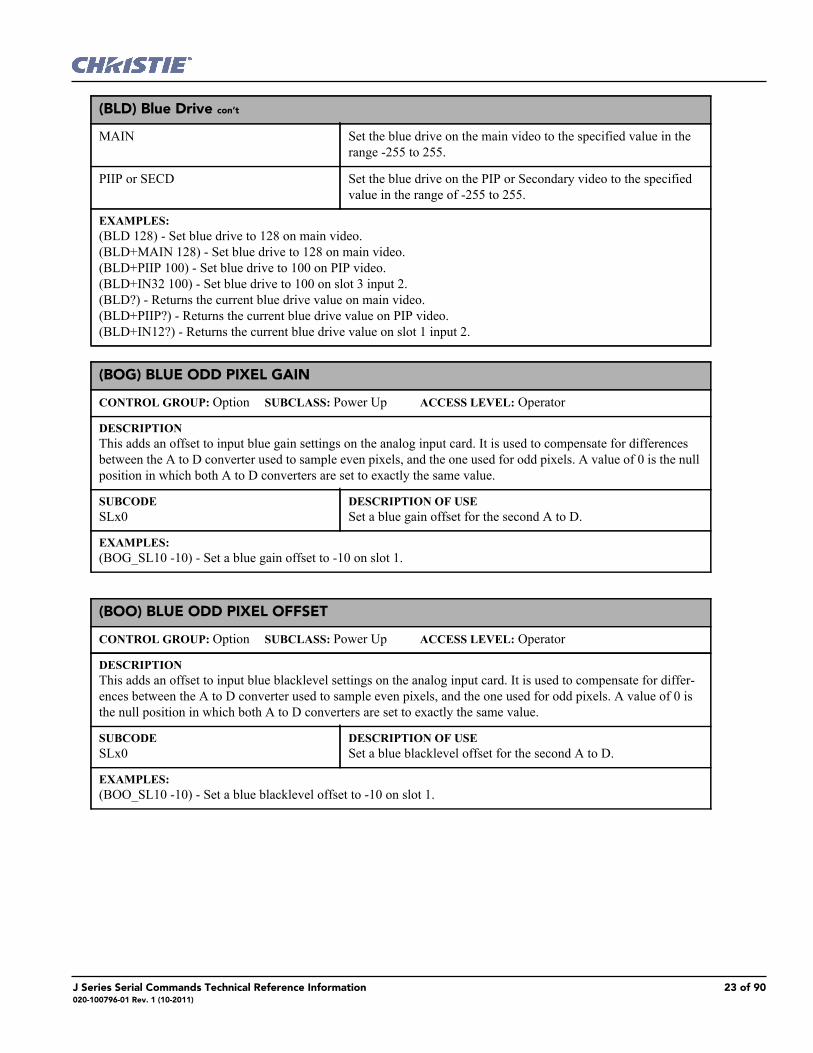
(BLD) Blue Drive con’t
MAIN Set the blue drive on the main video to the specified value in the range -255 to 255.
PIIP or SECD Set the blue drive on the PIP or Secondary video to the specified value in the range of -255 to 255.
EXAMPLES:(BLD 128) - Set blue drive to 128 on main video. (BLD+MAIN 128) - Set blue drive to 128 on main video.(BLD+PIIP 100) - Set blue drive to 100 on PIP video. (BLD+IN32 100) - Set blue drive to 100 on slot 3 input 2. (BLD?) - Returns the current blue drive value on main video. (BLD+PIIP?) - Returns the current blue drive value on PIP video. (BLD+IN12?) - Returns the current blue drive value on slot 1 input 2.
(BOG) BLUE ODD PIXEL GAIN
CONTROL GROUP: Option SUBCLASS: Power Up ACCESS LEVEL: Operator
DESCRIPTIONThis adds an offset to input blue gain settings on the analog input card. It is used to compensate for differences between the A to D converter used to sample even pixels, and the one used for odd pixels. A value of 0 is the null position in which both A to D converters are set to exactly the same value.
SUBCODESLx0
DESCRIPTION OF USESet a blue gain offset for the second A to D.
EXAMPLES:(BOG_SL10 -10) - Set a blue gain offset to -10 on slot 1.
(BOO) BLUE ODD PIXEL OFFSET
CONTROL GROUP: Option SUBCLASS: Power Up ACCESS LEVEL: Operator
DESCRIPTIONThis adds an offset to input blue blacklevel settings on the analog input card. It is used to compensate for differ-ences between the A to D converter used to sample even pixels, and the one used for odd pixels. A value of 0 is the null position in which both A to D converters are set to exactly the same value.
SUBCODESLx0
DESCRIPTION OF USESet a blue blacklevel offset for the second A to D.
EXAMPLES:(BOO_SL10 -10) - Set a blue blacklevel offset to -10 on slot 1.
J Series Serial Commands Technical Reference Information 23 of 90020-100796-01 Rev. 1 (10-2011)

(BRT) BRIGHTNESS
CONTROL GROUP: Input SUBCLASS: Power Up ACCESS LEVEL: Operator
DESCRIPTIONThe Brightness control adjusts the offset applied to the input signal. It has exactly the same effect as adjusting the input levels, except that it operates an all 3 colors and can be used to make quick adjustments. For precise control, the input level adjustments should be used. If the setting is too high, black portions of the image are displayed as dark grey, making the image appear washed-out. If the setting is too low, dark greys are displayed as deep black and detail is lost in the darkest parts of the image. This condition is known as 'crushing'. When adjusting, start from a lower setting and adjust upwards until just above the point where black is crushed.
SUBCODEINxy
DESCRIPTION OF USESet the brightness on slot x, input y to the specified value in the range of -1000 to 1000.
MAIN Set the brightness on the main video to the specified value in the range -1000 to 1000.
PIIP or SECD Set the brightness on the PIP or Secondary video to the specified value in the range of -1000 to 1000.
EXAMPLES:(BRT 500) -Set brightness to 500 on main video (BRT+MAIN 500) - Set brightness to 500 on main video. (BRT+PIIP -250) - Set brightness to -250 on PIP video. (BRT+IN32 100) - Set brightness to 100 on slot 3 input 2. (BRT?) - Returns the current brightness value on main video. (BRT+PIIP ?) - Returns the current brightness value on PIP video. (BRT+IN12 ?) - Returns the current brightness value on slot 1 input 2.
(BRU) BRIGHTNESS UNIFORMITY
CONTROL GROUP: Preference SUBCLASS: Power Down ACCESS LEVEL: Operator
DESCRIPTIONEnable/Disable brightness uniformity and adjust brightness uniformity output.
SUBCODESLCT
DESCRIPTION OF USEEnable/Disable Brightness Uniformity.
CRSA Enable/Disable BRU Coarse Adjustment.
UITL Get/Set the percent of gain at top left corner.
UIML Get/Set the percent of gain at left side.
UIBL Get/Set the percent of gain at bottom left corner.
UITR Get/Set the percent of gain at top right corner.
UIMR Get/Set the percent of gain at right side.
UIBR Get/Set the percent of gain at bottom right corner.
UIH1 Get/Set the percent of gain at left turn point.
24 of 90 J Series Serial Commands Technical Reference Information020-100796-01 Rev. 1 (10-2011)

(BRU) Brightness Uniformity con’t
UIH2 Get/Set the percent of gain at right turn point.
UI1P Get/Set position of left turn point.
UI2P Get/Set position of right turn point.
GAIN Get/Set overall gain.
UIRT Restore all parameters to factory default.
EXAMPLES:(BRU+ENAB?) - Get current state of brightness uniformity, 0 is disabled, 1 is enabled.(BRU+ENAB 1) - Enable brightness uniformity.
(CCD) OUTPUT COLOR DEFAULT
CONTROL GROUP: Preference SUBCLASS: Power Up ACCESS LEVEL: Operator
DESCRIPTIONSpecifies the default color adjustment to use for new channels. This allows the user to specify a standard color and have that color applied by default to all new sources. The user may override this for any specific channel.
SUBCODE<No Subcode>
DESCRIPTION OF USEApply a default table to use while running auto setup when a YNF filter is not in place.
DYNF Apply a default table to use while running auto setup when a YNF filter is in place.
EXAMPLE:(CCD 0) - Make new channels using the MAX drive table.
(CCI) INTERPOLATED COLOR
CONTROL GROUP: Input SUBCLASS: Power Up ACCESS LEVEL: Operator
DESCRIPTIONThis control generates an output color map based on interpolating the values for the standard color temperatures in the range of 3200K-9300K. It effectively allows you to adjust the color temperature of the image. The selected output color table must be on 'Color Temperature' to enable this control.
SUBCODEINxy
DESCRIPTION OF USESet the interpolated color temperature for slot x, input y.
MAIN Set the interpolated color temperature for main video.
PIIP or SECD Set the interpolated color temperature for PIP or Secondary video.
EXAMPLE:(CCI 9300) - Set the interpolated color temperature to 9300K for main video.
J Series Serial Commands Technical Reference Information 25 of 90020-100796-01 Rev. 1 (10-2011)

(CCS) SELECT OUTPUT COLOR
CONTROL GROUP: Input SUBCLASS: Power Up ACCESS LEVEL: Operator
DESCRIPTIONSelects which of several predefined and 4 user defined color maps to use for a specific input signal. 0 = MaxDrives - All color adjustments are turned off allowing the projector to run at maximum brightness. 2 = Color Temperature - This will allow you to specify a color temperature between 3200 and 9300 based on the setting of the Color Temperature control. Color temperature is expressed in degrees Kelvin [3200, 5400, etc.]. Lower numbers give a reddish white, higher numbers appear bluish. There are four standard settings. 9300K is close to the white of many computer monitors. 6500K is the standard for color video, in both standard- and high-definition forms. 5400K is a standard for graphics and black-and-white video. 3200K is useful if the projected image is to be filmed or shot as part of a studio set that is illuminated with incandescent lights. For all color tem-peratures, the color primaries [red, green & blue] are unchanged and reflect the native colors of the projector. 3 = SD Video - Optimized for SD video. This will allow you to adjust the color of red, green and blue, as well as the color of white. 4 = HD Video - Optimized for HD video. This will allow you to adjust the color of red, green and blue, as well as the color of white. 5 = User 1 - Selects a user defined sets of color adjustments. 6 = User 2 - Selects a user defined sets of color adjustments. 7 = User 3 - Selects a user defined sets of color adjustments. 8 = User 4 - Selects a user defined sets of color adjustments. The set of 4 User Defined settings are defined in the configuration menu.
SUBCODEINxy
DESCRIPTION OF USESelect the color temp setting for slot x, input y.
MAIN Select the color temp setting for main video.
PIIP or SECD Select the color temp setting for PIP or Secondary video.
EXAMPLE:(CCS 0) - Set the color temp setting to max drives for main video.
(CHA) CHANNEL
CONTROL GROUP: Unsaved SUBCLASS: Power Up ACCESS LEVEL: Operator
DESCRIPTIONSelect the channel to use, in the range 1-99. Switching channels will switch to the appropriate option card/input. If the signal signature in the channel does not match the signal on the channel's input, the channel change will switch to the “auto-channel” or to the channel that was defined for the signal signature that is on the channel's input. This command will fail if the data in the channel file does not match the current system hardware. This command can also be used to copy, delete and edit certain channel properties.
SUBCODECOPY
DESCRIPTION OF USEMake a copy of a channel, and assign it a unique number (option-ally, specify a new channel number).
DLET Delete a channel.
MAIN Set the channel being used by main.
PIIP or SECD Set the channel being used by PIP or Secondary.
INFO Display the information on the current channel.
26 of 90 J Series Serial Commands Technical Reference Information020-100796-01 Rev. 1 (10-2011)

(CHA) Channel con’t
EXAMPLES:(CHA?) Get current active channel. (CHA 10) Set main to channel 10. (CHA+PIIP 99) Set PIP to channel 99. (CHA+COPY 1) Make a copy of channel 1, using the next free channel number. (CHA+COPY 1 20) Make a copy of channel 1, and copy to channel 20 (will fail if 20 already exists). (CHA+DLET 0) Delete all unlocked channels. (CHA+DLET 20) Delete channel 20.
(CLE) COLOR ENABLE
CONTROL GROUP: Unsaved SUBCLASS: Power Up ACCESS LEVEL: Operator
DESCRIPTIONThis control allows the three primary colors (red, green and blue) to be turned on or off separately. It is used to look at the colors one at a time or in pairs when doing convergence, light measurements, etc. The list of values for this command are: 0 = White 1 = Red 2 = Green 3 = Blue 4 = Yellow 5 = Cyan 6 = Magenta
SUBCODE<No Subcode>
DESCRIPTION OF USESelect color or colors to display.
EXAMPLE:(CLE 1) - Display red portion of image only. (CLE 5) - Display green and blue portion of image only. (CLE 0) - Display image normally (all primaries).
(CLP) CLAMPING
CONTROL GROUP: Input SUBCLASS: Power Up ACCESS LEVEL: Operator
DESCRIPTIONFor all analog signals a clamping pulse is generated that defines where in the signal a black reference can be found. The Clamp Location sets the clamping pulse to one of three possible locations: tip, back porch & tri-level. For most signals the correct position is backporch, just after the sync pulse. If the signal has no back porch and there is no sync pulse in the RG or B signals, clamping can occur at the front or tip of the sync pulse. For HDTV signals [1080i & 720p] the clamp must be moved past the positive pulse of the tri-level sync pulse, so the tri-level option is correct. For almost all other signals, backporch is correct. Sync tip is needed only if the backporch is too small. For many signals, this control will have no effect. Change this setting only if the image appears unusually dim, has horizontal streaks, or shows significant color drift. Value Range: 0 = backporch 1 = sync tip 2 = tri-level
J Series Serial Commands Technical Reference Information 27 of 90020-100796-01 Rev. 1 (10-2011)

(CLP) Clamping con’t
SUBCODEINxy
DESCRIPTION OF USESet the black level clamping for slot x, input y.
MAIN Set the black level clamping for main video.
PIIP or SECD Set the black level clamping for PIP or Secondary video.
EXAMPLES:(CLP 1) - Set the black level clamping for main video to sync tip. (CLP+MAIN 1) - Set the black level clamping for main video to sync tip. (CLP+IN32 1) - Set the black level clamping for slot 3 input 2 to sync tip.
(CLR) COLOR
CONTROL GROUP: Input SUBCLASS: Power Up ACCESS LEVEL: Operator
DESCRIPTIONThis control adjusts the saturation (amount) of color in a video image.
SUBCODEINxy
DESCRIPTION OF USESet the color saturation on slot x, input y to the specified value in the range of 0-1000.
MAIN Set the color saturation on the main video to the specified value in the range 0-1000.
PIIP or SECD Set the color saturation on the PIP or Secondary video to the spec-ified value in the range of 0-1000.
EXAMPLES:(CLR 500) - Set color saturation to 500 on main video. (CLR MAIN 500) - Set color saturation to 500 on main video. (CLR PIP 250) - Set color saturation to 250 on PIP video. (CLR IN32 100) - Set color saturation to 100 on slot 3 input 2. (CLR ?) - Returns the current color saturation value on main video. (CLR PIP ?) - Returns the current color saturation value on PIP video. (CLR IN12 ?) - Returns the current color saturation value on slot 1 input 2.
(CON) CONTRAST
CONTROL GROUP: Input SUBCLASS: Power Up ACCESS LEVEL: Operator
DESCRIPTIONThis control sets the image contrast by adjusting the gain applied to the input signal. It has exactly the same effect as adjusting the input levels, except that it operates an all 3 colors and can be used to make quick adjustments. For precise control, the input level adjustments should be used. If the setting is too high, bright portions of the image that are not quite at peak white are displayed as peak white and detail is lost in the brightest parts of the image. This condition is known as 'crushing'. If the setting is too low, the image will be dimmer than it need be. Start from a lower setting and adjust upwards until just below the point where white is crushed.
SUBCODEINxy
DESCRIPTION OF USESet the contrast on slot x, input y to the specified value in the range of 0-1000.
28 of 90 J Series Serial Commands Technical Reference Information020-100796-01 Rev. 1 (10-2011)

(CON) Contrast con’t
MAIN Set the contrast on the main video to the specified value in the range 0-1000.
PIIP or SECD Set the contrast on the PIP or Secondary video to the specified value in the range of 0-1000.
EXAMPLES:(CON 500) - Set contrast to 500 on main video. (CON+MAIN 500) - Set contrast to 500 on main video. (CON+PIIP 250) - Set contrast to 250 on PIP video. (CON+IN32 100) - Set contrast to 100 on slot 3 input 2. (CON?) - Returns the current contrast value on main video. (CON+PIIP ?) - Returns the current contrast value on PIP video. (CON+IN12 ?) - Returns the current contrast value on slot 1 input 2.
(CRM) CHROMA/LUMA DELAY
CONTROL GROUP: Input SUBCLASS: Power Up ACCESS LEVEL: Operator
DESCRIPTIONChroma/Luma delay adjusts the time delay between the chroma and the luminance signals in decoded signals. Adjust the delay to eliminate shadows occurring with adjacent colors. It is useful only for video images processed by decoder cards.
SUBCODEINxy
DESCRIPTION OF USESet the luma delay on slot x, input y to the specified value in the range of -3 pixel to 3 pixel.
MAIN Set the luma delay on the main video to the specified value in the range -3 pixel to 3 pixel.
PIIP or SECD Set the luma delay on the PIP or Secondary video to the specified value in the range of -3 pixel to 3 pixel.
EXAMPLES:(CRM 3) - Set luma delay to 3 pixel on main video. (CRM MAIN 3) - Set luma delay to 3 pixel on main video. (CRM PIP 3) - Set luma delay to 3 pixel on PIP video. (CRM IN32 -3) - Set luma delay to -3 pixel on slot 3 input 2. (CRM ?) - Returns the current luma delay on main video. (CRM PIP ?) - Returns the current luma delay on PIP video. (CRM IN12 ?) - Returns the current luma delay on slot 1 input 2.
J Series Serial Commands Technical Reference Information 29 of 90020-100796-01 Rev. 1 (10-2011)

(CSP) COLOR SPACE
CONTROL GROUP: Input SUBCLASS: Power Up ACCESS LEVEL: Operator
DESCRIPTIONThis control specifies which color space the input signal uses. This determines how the color components are decoded for accurate color in the display. Color space control only applies to analog input signals. Although the proper color space is normally determined automatically by the projector, you can override the setting. Use RGB unless you are using component video. Use YPbPr(SDTV) for most video sources. Use YPbPr(HDTV) for high definition signals. NOTE: When certain RGB signals are first connected, the projector may not initially recognize them as RGB and may incorrectly decode their color information as YPbPr(SDTV). These signals can include: RGB signals in NTSC, PAL, SECAM frequency ranges, Scan-doubled sync-on-green, Scan-quadrupled sync-on-green. For these signals, change the Color Space to RGB, then define a new channel for future use. Values are: 0 = RGB 1 = YPbPr (SDTV) 2 = YPbPr (HDTV)
SUBCODEINxy
DESCRIPTION OF USESet the color space on slot x, input y.
MAIN Set the color space on main video.
PIIP or SECD Set the color space on PIP or Secondary video.
EXAMPLES:(CSP 1) - Set color space to YPbPr(SDTV) on main video. (CSP+MAIN 2) - Set color space to YPbPr(HDTV) on main video. (CSP+PIIP 1) - Set color space to YPbPr(SDTV) on PIP video. (CSP+IN32 1) - Set color space to YPbPr(SDTV) on slot 3 input 2. (CSP?) - Returns the current color space value on main video. (CSP+PIIP?) - Returns the current color space value on PIP video. (CSP+IN12?) - Returns the current color space value on slot 1 input 2.
(DED) DUAL DVI EDID TYPE SELECTION
CONTROL GROUP: Option SUBCLASS: Power Up ACCESS LEVEL: Operator
DESCRIPTIONSet the preferred EDID Timings on the Dual DVI input card. Available Models are:0 = Default1 = 3D2 = Custom
SUBCODESLxy
DESCRIPTION OF USESet the EDID timings on slot x to the specified type.
EXAMPLES:(DED+SL31 1) - Set EDID type to 1 (3D) on slot 3 input 1.(DED+SL12 ?) - Returns the current EDID type on slot 1 input 2.
30 of 90 J Series Serial Commands Technical Reference Information020-100796-01 Rev. 1 (10-2011)

(DEF) DEFAULTS
CONTROL GROUP: Unsaved SUBCLASS: Power Down ACCESS LEVEL: Admin
DESCRIPTIONThis control will reset all preference and configuration settings in the device to their default values. The value of 111 must be sent. This helps prevent accidental use of this control.
SUBCODE<No Subcode>
DESCRIPTION OF USERestore all factory defaults.
EXAMPLES:(DEF 111) - Restore all preferences, configurations, options, and unsaved controls to default.
(DLG) DATA LOGGING
CONTROL GROUP: Preference SUBCLASS: Power Down ACCESS LEVEL: Advanced
DESCRIPTIONSet data logging level. Levels are: 0 = Minimum logging of activities. Logging system errors, warnings and 'events' (i.e. power on/off, lamp on/off, user login/logout). 1 = Standard logging. Most activities logged - errors, warnings, events, and other info. 2 = Maximum logging. All activities are logged.
SUBCODE<No Subcode>
DESCRIPTION OF USESelect data logging level.
EXAMPLES: (DLG1) set current logging level to 1. (DLG?) get current logging level. Response is (DLG!001).
(DMX) DMX/ARTNET
CONTROL GROUP: Preference SUBCLASS: Power Up ACCESS LEVEL: Operator
DESCRIPTIONThe DMX control sets options for the DMX interface. It allows a user to select whether they want to receive data from both the DMX input card (inserted into the card cage in one of the input slots), or via ArtNet, an Ethernet based DMX protocol which monitors UDP port 6454. The Input termination (2 Watt, 120 Ohm) is required on the last DMXC card in a loop through configuration. (i.e. only on the last projector). Termination may be either hardware (by plugging in a termination dongle, etc) or may be switched in by software, but should not be both. Note that hardware termination is recommended, because software termination is only in place when the projector has AC applied. If there are cases where the network is required to be terminated without AC applied to the last projector, then a hardware terminator should be used
J Series Serial Commands Technical Reference Information 31 of 90020-100796-01 Rev. 1 (10-2011)

(DMX) DMX/Artnetcon’t
SUBCODE<No Subcode>
DESCRIPTION OF USESelects the source of the DMX/ArtNet input:0 = DMX Input Card and ArtNet - Monitors for data on both the DMX input card (if plugged in) and ArtNet. If the DMX card is actively receiving data, ArtNet will be ignored. 1 = DMX Input Card Only - Only monitors the DMX card for input 2 = ArtNet Only - Only monitors ArtNet for input 3 = Disabled - Both interfaces are disabled
CHAN Sets the base channel for the DMX device. Generally used if there are multiple projectors on a single subnet/universe i.e. the first pro-jector would use base channel 0. If using the basic personality (20 channels), the 2nd projector should use base channel 21. The DMX specification allows for overlap, but this is likely undesir-able. Note: The Base channel setting must allow enough space for the channels required by the selected personality.i.e. If the Basic Personality is selected, the Base Channel may be in the range 1-492. If the Advanced Personality is selected, the Base Channel may be in the range 1-448
PERS Sets the DMX personality. A personality represents a set of chan-nels the application will monitor for changes.Values:Show (0) - A minimal personality composed of controls most likely to be used while a show is runningSetup (1) - Contains all of the show controls plus additional con-trols used for setting up a showZAP (2) - Special personality which uses locks for critical func-tions (cannot be used with an all-slider type board.
TERM Switches termination resistance in/out of the circuit. If software termination is to be used on the DMX input card, this control should be enabled. If this control is not enabled, a physical termi-nator should be used. It may be necessary to clear this setting upon card removal. By default SW termination is disabled.
UNVS This control specifies which universe the projector belongs to, so it can filter out all other data packets. The Universe applies to ArtNet only, and does not apply to the DMXC input card.
SUBN This control sets the subnet for this projector. This is not to be con-fused with a subnet mask. A subnet identifies a set of universes. The subnet and universe in combination uniquely identify the channels a projector is listening on. The Subnet applies to ArtNet only, and does not apply to the DMXC input card.
FLTR If you have a noisy Analog to Digital converter in your DMX/Art-Net device (output oscillates between two values), this filter can be used to eliminate the input noise at the cost of fine control resolu-tion in some controls. By default this filter is set to 0 (Off). It is not recommended to use this feature unless you are experiencing prob-lems with your DMX input.
32 of 90 J Series Serial Commands Technical Reference Information020-100796-01 Rev. 1 (10-2011)
(DMX) DMX/ArtNet con’t
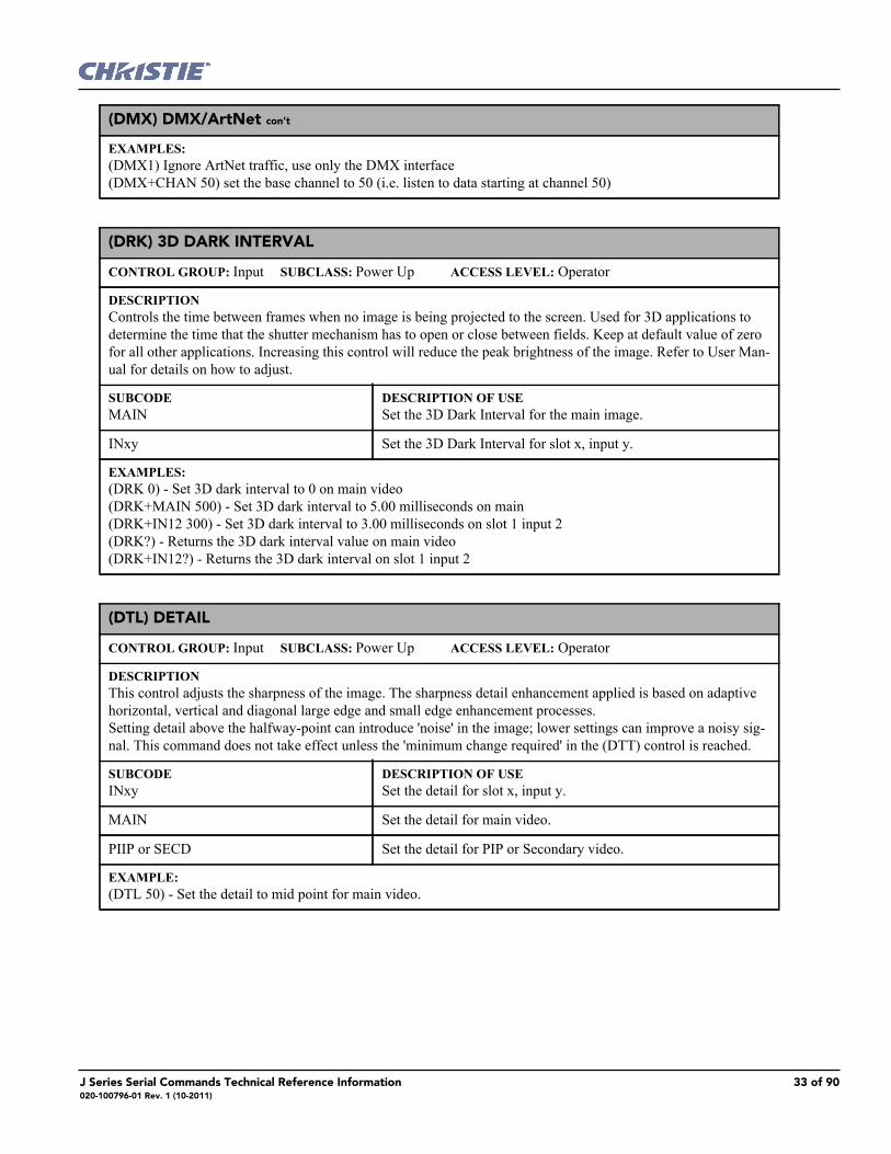
EXAMPLES:(DMX1) Ignore ArtNet traffic, use only the DMX interface(DMX+CHAN 50) set the base channel to 50 (i.e. listen to data starting at channel 50)
(DRK) 3D DARK INTERVAL
CONTROL GROUP: Input SUBCLASS: Power Up ACCESS LEVEL: Operator
DESCRIPTIONControls the time between frames when no image is being projected to the screen. Used for 3D applications to determine the time that the shutter mechanism has to open or close between fields. Keep at default value of zero for all other applications. Increasing this control will reduce the peak brightness of the image. Refer to User Man-ual for details on how to adjust.
SUBCODEMAIN
DESCRIPTION OF USESet the 3D Dark Interval for the main image.
INxy Set the 3D Dark Interval for slot x, input y.
EXAMPLES:(DRK 0) - Set 3D dark interval to 0 on main video(DRK+MAIN 500) - Set 3D dark interval to 5.00 milliseconds on main (DRK+IN12 300) - Set 3D dark interval to 3.00 milliseconds on slot 1 input 2(DRK?) - Returns the 3D dark interval value on main video(DRK+IN12?) - Returns the 3D dark interval on slot 1 input 2
(DTL) DETAIL
CONTROL GROUP: Input SUBCLASS: Power Up ACCESS LEVEL: Operator
DESCRIPTIONThis control adjusts the sharpness of the image. The sharpness detail enhancement applied is based on adaptive horizontal, vertical and diagonal large edge and small edge enhancement processes. Setting detail above the halfway-point can introduce 'noise' in the image; lower settings can improve a noisy sig-nal. This command does not take effect unless the 'minimum change required' in the (DTT) control is reached.
SUBCODEINxy
DESCRIPTION OF USESet the detail for slot x, input y.
MAIN Set the detail for main video.
PIIP or SECD Set the detail for PIP or Secondary video.
EXAMPLE:(DTL 50) - Set the detail to mid point for main video.
J Series Serial Commands Technical Reference Information 33 of 90020-100796-01 Rev. 1 (10-2011)

(DTO) DETAIL OVERSHOOT
CONTROL GROUP: Input SUBCLASS: Power Up ACCESS LEVEL: Operator
DESCRIPTIONDetail overshoot / undershoot control is provided to minimize ringing on the enhanced edges detail and texture effects.
SUBCODEINxy
DESCRIPTION OF USESet the detail overshoot for slot x, input y.
MAIN Set the detail overshoot for main video.
PIIP or SECD Set the detail overshoot for PIP or Secondary video.
EXAMPLE:(DTO 50) - Set the detail overshoot to mid point for main video.
(DTT) DETAIL THRESHOLD
CONTROL GROUP: Input SUBCLASS: Power Up ACCESS LEVEL: Operator
DESCRIPTIONDetail threshold selects a filter sensitivity to noise. A higher value may improve noisy sources especially for higher settings of detail. This control sets the minimum change required before the detail (DTL) function is activated. This allows images to be sharpened without increasing the background noise.
SUBCODEINxy
DESCRIPTION OF USESet the detail threshold for slot x, input y.
MAIN Set the detail threshold for main video.
PIIP or SECD Set the detail threshold for PIP or Secondary video.
EXAMPLE:(DTT 50) - Set the detail threshold to mid point for main video.
(EBB) BLACKLEVEL BLENDING
CONTROL GROUP: Config SUBCLASS: Preference ACCESS LEVEL: Operator
DESCRIPTIONThe Black Level Blending control allows for Black Level Blending. Black Level Blending is the process of mod-ifying the pixels in the bright overlapping areas that result from the overlapping of two or more images. Correct adjustment eliminates uneven black levels by matching up black area hues with a target area hue (the intersection of the center lines), and adjusting the overlaps (edges) surrounding the target area. Use the black test pattern to perform this function.
SUBCODESLCT
DESCRIPTION OF USEEnables or disables black level blending mode, or choose a saved twist black level blending preset.
CNTV Changes edge blending black level in the center zone.
TOPV Changes edge blending black level in the top zone.
LFTV Changes edge blending black level in the left zone.
34 of 90 J Series Serial Commands Technical Reference Information020-100796-01 Rev. 1 (10-2011)

(EBB) Blacklevel Blending con’t
RHTV Changes edge blending black level in the right zone.
BTMV Changes edge blending black level in the bottom zone.
TLTV Changes edge blending black level in the top-left zone.
TRTV Changes edge blending black level in the top-right zone.
BLTV Changes edge blending black level in the bottom-left zone.
BRTV Changes edge blending black level in the bottom-right zone.
LFTW Changes edge blending black level width of the left zone.
RHTW Changes edge blending black level width of the right zone.
TOPW Changes edge blending black level width of the top zone.
BTMW Changes edge blending black level width of the bottom zone.
RSTD Reset all black level blending parameters to default values.
EXAMPLE:(EBB+CNTV 100) - Set black level blend offset of center zone to 100.(EBB+LFTW 200) - Set black level blend width of left zone to 200.(EBB+RHTW?) - Get black level blend width of right zone.
(EBL) EDGE BLENDING
CONTROL GROUP: Config/Preference SUBCLASS: Power Up ACCESS LEVEL: Operator
DESCRIPTIONThis control the edge blending settings so that any of the four edges can be blended with an adjacent projector to achieve an overlapped and seamless image.
SUBCODESLCT
DESCRIPTION OF USEEnables or Disables standard edge blending mode, or choose a saved Twist blending preset.
LFTW Changes edge blending width of the left edge.
LFTM Changes edge blending curve midpoint of the left edge.
LFTS Changes edge blending curve slope at the midpoint on the left edge.
RHTW Changes edge blending width of the right edge.
RHTM Changes edge blending curve midpoint of the right edge.
RHTS Changes edge blending curve slope at the midpoint on the right edge.
TOPW Changes edge blending width of the top edge.
TOPM Changes edge blending curve midpoint of the top edge.
J Series Serial Commands Technical Reference Information 35 of 90020-100796-01 Rev. 1 (10-2011)
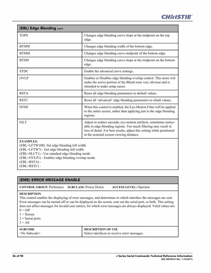
(EBL) Edge Blending con’t
TOPS Changes edge blending curve slope at the midpoint on the top edge.
BTMW Changes edge blending width of the bottom edge.
BTMM Changes edge blending curve midpoint of the bottom edge.
BTMS Changes edge blending curve slope at the midpoint on the bottom edge.
STDC Enable the advanced curve settings.
OVLP Enables or Disables edge blending overlap control. This more will make the active portion of the Blend zone very obvious and is intended to make setup easier.
RSTA Reset all edge blending parameters to default values.
RSTC Reset all ‘advanced’ edge blending parameters to efault values.
DTHF When this control is enabled, the Eye-Motion Filter will be applied to the entire screen, rather than applying just to the edge blending regions.
FILT Adjust to reduce saccadic eye-motion artifacts, sometimes notice-able in edge blending regions. Too much filtering may result in loss of detail. For best results, adjust this setting while positioned at the nominal screen-viewing distance.
EXAMPLES:(EBL+LFTW100) -Set edge blending left width.(EBL+LFTW?) - Get edge blending left width. (EBL+SLCT1) - Use standard edge blending mode.(EBL+OVLP1) - Enables edge blending overlap mode. (EBL+RSTA) -(EBL+RSTC) -
(EME) ERROR MESSAGE ENABLE
CONTROL GROUP: Preference SUBCLASS: Power Down ACCESS LEVEL: Operator
DESCRIPTIONThis control enables the displaying of error messages, and determines to which interface the messages are sent. Error messages can be turned off or can be displayed on the screen, sent out the serial port, or both. This setting does not affect messages for invalid user entries, for which error messages are always displayed. Valid values are: 0 = Off 1 = Screen 2 = Serial ports 3 = All
SUBCODE<No Subcode>
DESCRIPTION OF USESelect interfaces to receive error messages.
36 of 90 J Series Serial Commands Technical Reference Information020-100796-01 Rev. 1 (10-2011)

(EME) Error Message Enable con’t
EXAMPLES:(EME ?) Get current Error Message Enable state. (EME 1) Direct error messages to the screen.
(ESC) EDIT SECONDARY CHANNEL SETTING
CONTROL GROUP: Preference SUBCLASS: Power Up ACCESS LEVEL: Operator
DESCRIPTIONIn Interleaved 3D mode, this control allows the user the option to independently control primary and secondary channel settings, or to use the same setting for both links. By default, this control is unchecked, meaning any set-tings applied to the primary input will also be applied to the secondary input. In this case, the secondary channel settings cannot be set directly by the user. When checked, the secondary channel settings become editable.
SUBCODE<No Subcode>
DESCRIPTION OF USESet primary/secondary channel independence for Interleaved 3D mode.
EXAMPLE:(ESC 1) Enable editing of secondary channel/input settings.
(FAD) FADE TIME
CONTROL GROUP: Preference SUBCLASS: Power Down ACCESS LEVEL: Operator
DESCRIPTIONControls the amount of time it takes to fade between images on a source switch. It also fades in the PIP and OSD if possible.
SUBCODE<No Subcode>
DESCRIPTION OF USETime in hundredths of a second to allow the fade. Range 0 - 150 where 150 = 1.5 seconds, 1 = 10ms, 0 = off.
EXAMPLE:(FAD 100) - Fade for 1 second.
(FAS) FAN ASSIST SWITCH
CONTROL GROUP: Saved SUBCLASS: Power Down ACCESS LEVEL: Operator
DESCRIPTIONEnables or disables the ability for all fans to operate at maximum speed during a thermal over-temp condition.
SUBCODE<No Subcode>
DESCRIPTION OF USEEnable or disable maximum fan operation.
EXAMPLES:(FAS 1) - Turn on fan assist.(FAS 0) - Turn off fan assist.
J Series Serial Commands Technical Reference Information 37 of 90020-100796-01 Rev. 1 (10-2011)

(FCS) FOCUS LENS POSITION ADJUSTMENT
CONTROL GROUP: Configuration SUBCLASS: Power Up ACCESS LEVEL: Operator
DESCRIPTIONMove the focus motor to a specified position. The default data range is -1200 to 1200. The range may change after running the Lens Calibration function, which determines the full range allowed by the hardware.
SUBCODE<No Subcode>
DESCRIPTION OF USEAdjust the lens focus offset to a specific position.
EXAMPLE:(FCS 500) - Move lens focus to position 500.
(FIL) FILTER
CONTROL GROUP: Input SUBCLASS: Power Up ACCESS LEVEL: Operator
DESCRIPTIONApply an internal Low Pass Filter to the current input signal, before the A/D conversion in analog cards. This removes high frequency noise from input signals. HDTV is typically used for 720p and 1080i video sources. The high bandwidth filter should be used for 1080p or higher frequency sources. Valid values are: 0 = Off 1 = HDTV-High Bandwidth 2 = HDTV 3 = EDTV 4 = SDTV
SUBCODEINxy
DESCRIPTION OF USESet the filter for slot x, input y.
MAIN Set the filter for main video.
PIIP or SECD Set the filter for PIP or Secondary video.
EXAMPLES:(FIL 2) - Set the filter for main video to HDTV. (FIL+MAIN 2) - Set the filter for main video to HDTV. (FIL+IN32 2) - Set the filter for slot 3 input 2 to HDTV.
(FLE) FRAME LOCK ENABLE
CONTROL GROUP: Preference SUBCLASS: Power Up ACCESS LEVEL: Operator
DESCRIPTIONThis control enables or disables Frame Lock, which controls how the projector controls the output frame timing based on the input signal. When set to Frame Lock, output image frames are locked to the input if possible. When locked, the output is always locked to the primary input, never the PIP image. Free Run sets the output to close to 60Hz for all sources. This control must be set to locked if a 3D-Stereo signal is used.
SUBCODE<No Subcode>
DESCRIPTION OF USEEnables or Disables frame lock.
38 of 90 J Series Serial Commands Technical Reference Information020-100796-01 Rev. 1 (10-2011)

(FLE) Frame Lock Enable con’t
EXAMPLES:(FLE 0) - Free Run output.(FLE 1) - Enables frame lock. (FLE ?) - Get frame lock enabled status.
(FLW) SERIAL FLOW CONTROL
CONTROL GROUP: Preference SUBCLASS: Power Down ACCESS LEVEL: Advanced
DESCRIPTIONSet the flow control for a serial communications port.
SUBCODEPRTA
DESCRIPTION OF USESet the mode on port A (RS232 IN).
PRTB Set the mode on port B (RS232 OUT).
PRTC Set the mode on port C (RS422).
EXAMPLES:(FLW+PRTA "NONE") - Set no flow control on port A. (FLW+PRTA "SOFTWARE") - Set flow control on port A to software. (FLW+PRTA?) - Get flow control (FLW+PRTA!"SOFTWARE")
(FMD) FILM MODE DETECT
CONTROL GROUP: Input SUBCLASS: Power Up ACCESS LEVEL: Operator
DESCRIPTIONEnable or disable film motion detection. This is only available for interlaced or segmented frame sources. Valid values are: 0 = Disabled 1 = Auto 2 = PsF
SUBCODEINxy
DESCRIPTION OF USESet the film mode detect for slot x, input y.
MAIN Set the film mode detect for main video.
PIIP or SECD Set the film mode detect for PIP or Secondary video.
EXAMPLE:(FMD 1) - Enable auto film mode detect for main video.
J Series Serial Commands Technical Reference Information 39 of 90020-100796-01 Rev. 1 (10-2011)

(FRD) FRAME DELAY
CONTROL GROUP: Preference SUBCLASS: Power Up ACCESS LEVEL: Operator
DESCRIPTIONDelays the output signal timing relative to the input signal timing by a fraction of a frame, and up to several frames. The minimum latency can vary based on the amount of scaling applied to the image. When using key-stone or warping, an additional latency is required, depending on the amount of warp. The control is only avail-able when the input signal is frame locked. In free run mode, or in cases where the signal cannot be frame locked, the minimum latency defined by the scaling and keystoned/warp is applied to the signal.
SUBCODE<No Subcode>
DESCRIPTION OF USESet the amount of delay.
EXAMPLE:(FRD 1500) - Delay 1.5 frames.
(FRF) FREE RUN FREQUENCY
CONTROL GROUP: Preference SUBCLASS: Power Up ACCESS LEVEL: Operator
DESCRIPTIONThis controls sets the output video vertical frequency.
SUBCODE<No Subcode>
DESCRIPTION OF USESet the output vertical frequency, used when running in ‘Free Run” mode. See (FLE) Frame Lock Enable.
EXAMPLES:(FRF 5000) - Set free run frequency to 50 Hz. (FRF ?) - Get free run frequency.
(FRZ) FREEZE IMAGE
CONTROL GROUP: Unsaved SUBCLASS: Power Up ACCESS LEVEL: Operator
DESCRIPTIONFreeze the display image. This allows a detailed examination of a single frame of an otherwise moving image. Switching channels/inputs automatically switches the projector to unfrozen.
SUBCODEMAIN
DESCRIPTION OF USEFreeze or un-freeze the main image (1=freeze, 0=unfreeze).
PIIP or SECD Freeze or un-freeze the PIP or Secondary image (1=freeze, 0=unfreeze).
EXAMPLE:(FRZ+MAIN 1) - Freeze the main image.
(FTB) FADE TO BLACK
CONTROL GROUP: Preference SUBCLASS: Power Up ACCESS LEVEL: Operator
DESCRIPTIONFades the image to/from black over the time period specified.
40 of 90 J Series Serial Commands Technical Reference Information020-100796-01 Rev. 1 (10-2011)

(FTB) Fade to Black con’t
SUBCODE<No Subcode>
DESCRIPTION OF USESet the image intensity 0-1000, where 1000 = 100.0% image, and 0 = 0% image (black)
TIME Set a fade time in milliseconds 0 - 10000.
SLCT Select a fade. 0 = fade to black and 1 = fade back to image.
EXAMPLES:(FTB500) - Set image intensity to 50.0%. (FTB+TIME3000) - Set the fade time to 3 seconds.(FTB+SLCT 0) - Fade to black over the time specified by. (FTB+TIME x) (FTB+SLCT 1) - Restore image over the time specified by (FTB+TIME x).
(GAM) GAMMA CORRECTION
CONTROL GROUP: Preference SUBCLASS: Power Down ACCESS LEVEL: Operator
DESCRIPTIONThe Gamma Correction control is used to correct ambient conditions affecting the display. The Gamma control affects the shape of the curve determining what grey shades are displayed for a given amount of signal input between minimum (black) and maximum (white). This is done by performing a linear transform from the user selected gamma channel setting. The normal point is 0, meaning the selected gamma table is used unaltered. If there is a lot of ambient light, the image can become washed out, making it difficult or impossible to see details in dark areas. Increasing the gamma correction setting can compensate for this by transforming the curve towards a gamma of 1.0. Decreasing the control shall transform the gamma towards a gamma of 3.0.
SUBCODE<No Subcode>
DESCRIPTION OF USESet the interpolated gamma level.
EXAMPLES: (GAM 100) - Set gamma to 1.0 curve. (GAM?) - Returns current gamma curve.
(GIA) ANALOG BNC GROUNDED INPUT SELECTION
CONTROL GROUP: Option SUBCLASS: Power Up ACCESS LEVEL: Operator
DESCRIPTIONSet the input signal grounding method to single-ended or differential. Valid values are: 0 = Differential (default) 1 = Single-ended
SUBCODESLxy
DESCRIPTION OF USESet the input signal grounding method for the specified slot and input.
EXAMPLES:(GIA+SL31 1) - Set grounding on slot 3 input 1 to single-ended. (GIA+SL11 ?) - Returns the current grounding method of slot 1 input 1.
J Series Serial Commands Technical Reference Information 41 of 90020-100796-01 Rev. 1 (10-2011)

(GID) VIDEO DECODER GROUNDED INPUT SELECTION
CONTROL GROUP: Option SUBCLASS: Power Up ACCESS LEVEL: Operator
DESCRIPTIONSet the input signal grounding method to single-ended or differential. Valid values are: 0 = Differential (default) 1 = Single-ended
SUBCODESLxy
DESCRIPTION OF USESet the input signal grounding method for the specified slot and input.
EXAMPLES:(GID+SL31 1) - Set grounding on slot 3 input 1 to single-ended. (GID+SL16 ?) - Returns the current grounding method of slot 1 input 6.
(GIO) GENERAL PURPOSE INPUT/OUTPUT
CONTROL GROUP: Config SUBCLASS: Power Down ACCESS LEVEL: Advanced
DESCRIPTIONControl or monitor the state of the General Purpose Inputs and Outputs. The strings have one character for each hardware connector pin, and from left to right, correspond to the pin num-bers 2,3,4,6,7,8,9. (Pin 1 is 12V and Pin 5 is Ground - they cannot be read, set or configured).A low state (or value of 0) will be read on an input pin if the circuit attached to the pin is open. A high state (or value of 1) will be read on an input pin if the circuit attached to the pin is shorted to ground. This corresponds to a switch closing event.
SUBCODECNFG
DESCRIPTION OF USESet the Direction for the individual pins to inputs or outputs.
STAT Get the state of all Inputs, or set the state of all outputs.
EXAMPLES:(GIO+STAT?) - Get status of all the inputs. Returns (GIO+STAT!"LLLLLLL") - All inputs are low. (GIO+STAT "HXLHLLL") - Set status of the GPOs - 2 high, 3 no change, 4 Low, 6 High, 7 Low, 8 Low, 9 Low. (GIO+STAT "HHHXXXX" 500) - Will pulse the first three pins (physical connector pins 2, 3 & 4) for 500 ms. (GIO+STAT "111XXXX" 500) - Same pulsing pattern as above (1's and 0's still work for pulsing - but preferred method is to use H and Ls) (GIO+STAT "XXXHLXX" 1000) - Will pulse pin 6 in a low/high/low pattern and pin 7 high/low/high for 1000 ms. (GIO+STAT "XXX10XX" 1000) - Same pulsing pattern as above (1's and 0's still work for pulsing - but preferred method is to use H and Ls) (GIO+CNFG "IIOOOIO") - Set pins 2, 3 and 8 to Input, 4, 6, 7 and 9 to Output (letter 'Oh', not zero) (GIO+CNFG "OOxxxxx") - Set pins 2, and 3 to Output, ignore the rest (letter 'Oh', not zero)
42 of 90 J Series Serial Commands Technical Reference Information020-100796-01 Rev. 1 (10-2011)

(GMS) VDIC GROUPED-INPUTS MODE
CONTROL GROUP: Option SUBCLASS: Power Down ACCESS LEVEL: Operator
DESCRIPTIONAllows users to select a mode to group the last 3 BNC connectors (input 4/5/6) on a Video Decoder Input Card. valid options are: 0 = 3 CVBS sources 1 = 1 SVideo Source + 1 CVBS source 2 = 1 YPrPb (Component) source
SUBCODESLx0
DESCRIPTION OF USESet a grouping mode for the last 3 BNC connectors on Video Decoder card in the selected slot.
EXAMPLES:(GMS+SL10 0) - Use 3 BNC connectors for CVBS source. (GMS+SL10 1) - Use 3 BNC connectors for 1 SVideo and 1 CVBS sources. (GMS+SL10 2) - Use 3 BNC connectors for 1 YPbPr(component) source.(GMS+SL10 ?) - Get the current mode setting.
(GNB) GREEN BLACK LEVEL
CONTROL GROUP: Input SUBCLASS: Power Up ACCESS LEVEL: Operator
DESCRIPTIONGreen black level is used to compensate for relative variations in the blacklevels between Red, Green and Blue. This is available on all cards expect the Video decoder. The correct setting achieves maximum contrast without crushing white or black. When the drive and black level controls are set correctly for a signal, the Comprehensive Color Adjustment, including color temperature, will work as expected. The drive and black level controls should not be used to setup a specific color temperature as this will require separate color temperature adjustments to be made for each signal.
SUBCODEINxy
DESCRIPTION OF USESet the green black level on slot x, input y to the specified value in the range of -255 to 255.
MAIN Set the green black level on the main video to the specified value in the range -255 to 255.
PIIP or SECD Set the green black level on the PIP or Secondary video to the specified value in the range of -255 to 255.
EXAMPLES:(GNB 128) - Set green black level to 128 on main video. (GNB+MAIN 128) - Set green black level to 128 on main video. (GNB+PIIP 100) - Set green black level to 100 on PIP video. (GNB+IN32 100) - Set green black level to 100 on slot 3 input 2. (GNB?) - Returns the current green black level value on main video. (GNB+PIIP ?) - Returns the current green black level value on PIP video. (GNB+IN12 ?) - Returns the current green black level value on slot 1 input 2.
J Series Serial Commands Technical Reference Information 43 of 90020-100796-01 Rev. 1 (10-2011)
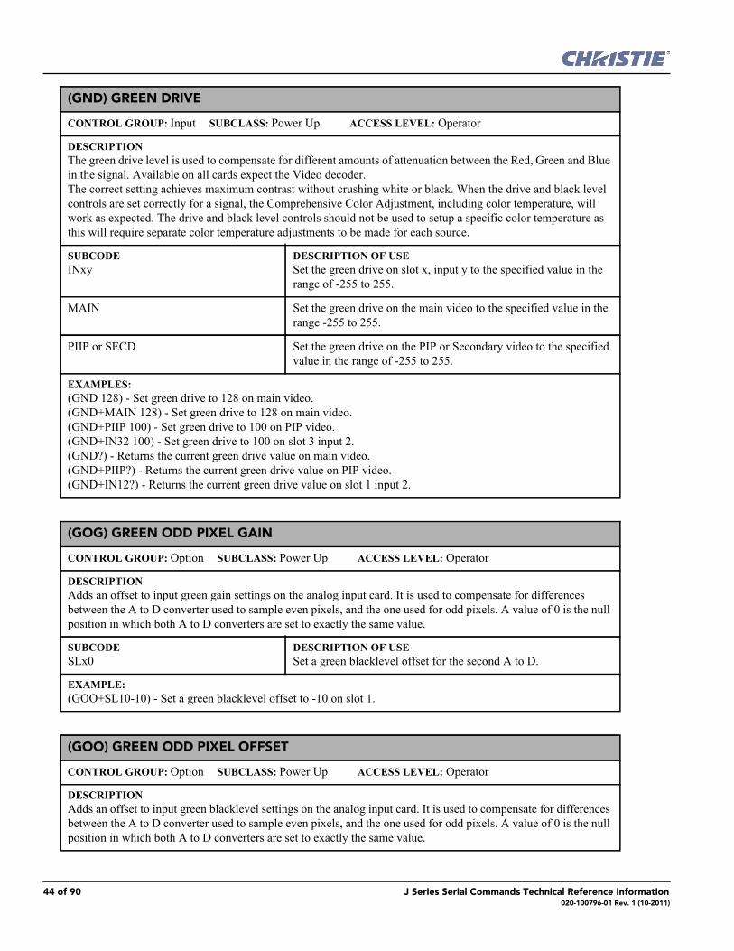
(GND) GREEN DRIVE
CONTROL GROUP: Input SUBCLASS: Power Up ACCESS LEVEL: Operator
DESCRIPTIONThe green drive level is used to compensate for different amounts of attenuation between the Red, Green and Blue in the signal. Available on all cards expect the Video decoder. The correct setting achieves maximum contrast without crushing white or black. When the drive and black level controls are set correctly for a signal, the Comprehensive Color Adjustment, including color temperature, will work as expected. The drive and black level controls should not be used to setup a specific color temperature as this will require separate color temperature adjustments to be made for each source.
SUBCODEINxy
DESCRIPTION OF USESet the green drive on slot x, input y to the specified value in the range of -255 to 255.
MAIN Set the green drive on the main video to the specified value in the range -255 to 255.
PIIP or SECD Set the green drive on the PIP or Secondary video to the specified value in the range of -255 to 255.
EXAMPLES:(GND 128) - Set green drive to 128 on main video. (GND+MAIN 128) - Set green drive to 128 on main video. (GND+PIIP 100) - Set green drive to 100 on PIP video. (GND+IN32 100) - Set green drive to 100 on slot 3 input 2. (GND?) - Returns the current green drive value on main video. (GND+PIIP?) - Returns the current green drive value on PIP video. (GND+IN12?) - Returns the current green drive value on slot 1 input 2.
(GOG) GREEN ODD PIXEL GAIN
CONTROL GROUP: Option SUBCLASS: Power Up ACCESS LEVEL: Operator
DESCRIPTIONAdds an offset to input green gain settings on the analog input card. It is used to compensate for differences between the A to D converter used to sample even pixels, and the one used for odd pixels. A value of 0 is the null position in which both A to D converters are set to exactly the same value.
SUBCODESLx0
DESCRIPTION OF USESet a green blacklevel offset for the second A to D.
EXAMPLE:(GOO+SL10-10) - Set a green blacklevel offset to -10 on slot 1.
(GOO) GREEN ODD PIXEL OFFSET
CONTROL GROUP: Option SUBCLASS: Power Up ACCESS LEVEL: Operator
DESCRIPTIONAdds an offset to input green blacklevel settings on the analog input card. It is used to compensate for differences between the A to D converter used to sample even pixels, and the one used for odd pixels. A value of 0 is the null position in which both A to D converters are set to exactly the same value.
44 of 90 J Series Serial Commands Technical Reference Information020-100796-01 Rev. 1 (10-2011)

(GOO) Green Odd Pixel Offset con’t
SUBCODESLx0
DESCRIPTION OF USESet a green blacklevel offset for the second A to D.
EXAMPLE:(GOO+SL10-10) - Set a green blacklevel offset to -10 on slot 1.
(HDC) DHDIC DUAL-LINK CONFIGURATION
CONTROL GROUP: Option SUBCLASS: Power Down ACCESS LEVEL: Operator
DESCRIPTIONSelect whether to use the 2 inputs as separate inputs, or combined as a dual-link. Select 'Automatic' to let the card decide, based on the input signal. If the card cannot determine this, it will assume 2 single links. Valid values are: 0 = Automatic 1 = 2 Single Links 2 = Dual Link
SUBCODESLx0
DESCRIPTION OF USESet a single/dual-link mode for the DHDIC.
EXAMPLES:(HDC+SL10 0) - Use Automatic detection for DHDIC on slot 1. (HDC+SL40 1) - Use 2 Single Links for DHDIC on slot 4. (HDC+SL10 2) - Use Dual-link for DHDIC on slot 1. (HDC+SL10 ?) - Get the current dual-link mode for DHDIC on slot 1.
(HIS) LAMP HISTORY
CONTROL GROUP: Configuration SUBCLASS: Power Down ACCESS LEVEL: Status
DESCRIPTIONRetrieve the history of installed lamp entries, including the current lamp. There is an individual entry for each lamp in the history. The format for each entry is: (HIS!AAA BBB "C" "D" "E" "F" GGG HHH "I") A = List IndexB = Lamp NumberC = Serial NumberD = Install DateE = Uninstall DateF = Lamp TypeG = Total Number of StrikesH = Number of Failed StrikesI = Hours in (h:m) format
SUBCODE<No Subcode>
DESCRIPTION OF USERetrieve the lamp history for the lamps that have been installed in both lamp positions.
LMP1 Retrieve the lamp history for the lamps that have been installed in position 1.
J Series Serial Commands Technical Reference Information 45 of 90020-100796-01 Rev. 1 (10-2011)

(HIS) Lamp History con’t
EXAMPLES:(HIS?) (HIS!000 001 "12A345B" "20:00:27 23/09/2008" "03:10:39 24/09/2008" "2462732-00" 010 000 0435)(HIS!000 002 "8995474C" "10:10:39 23/09/2008" "06:15:31 15/10/2008" "2462732-00" 005 001 0201)
(HLP) SERIAL HELP
CONTROL GROUP: Unsaved SUBCLASS: Power Down ACCESS LEVEL: Status
DESCRIPTIONQuery a list of all available serial commands, with brief descriptions and current enabled states.
SUBCODE<No Subcode>
DESCRIPTION OF USERequest entire command help listing, or list for a single command.
EXAMPLES:(HLP?) - Retrieve entire command help listing. (HLP? "BRT") - Retrieve all subcodes/descriptions/enables for BRT control.
(HLT) PROJECTOR HEALTH
CONTROL GROUP: Unsaved SUBCLASS: Power Down ACCESS LEVEL: Operator
DESCRIPTIONAny system health errors are placed on the troubleshooting queue. The queue, which contains the problems and a suggested solution for each one, is read-only. All problems in the queue are read using their index number, which starts from 0.Problems are assigned priorities:1) Critical - will result in failure to operate or shutdown2) High - will result in significant loss of functionality but the projector may continue to run3) Low - will result in minor loss of functionality which will not seriously affect projector
SUBCODELSOL
DESCRIPTION OF USEList solutions.
LALL List one or all problems and solutions.
EXAMPLES:(HLT?) - Returns all queued problems. (HLT? 3) - Returns problem index 3 in the queue.(HLT+LSOL? 4) - Returns the solution hint for problem index 4 in the queue.(HLT+LALL?) - Returns all queued problems and their solutions.(HLT+LALL? 3) - Returns problem index 3 and its’ solution.
(HOR) HORIZONTAL POSITION
CONTROL GROUP: Input SUBCLASS: Power Up ACCESS LEVEL: Operator
DESCRIPTIONMove the horizontal position of the image left or right.
SUBCODEMAIN
DESCRIPTION OF USESet the horizontal position for the main image.
46 of 90 J Series Serial Commands Technical Reference Information020-100796-01 Rev. 1 (10-2011)
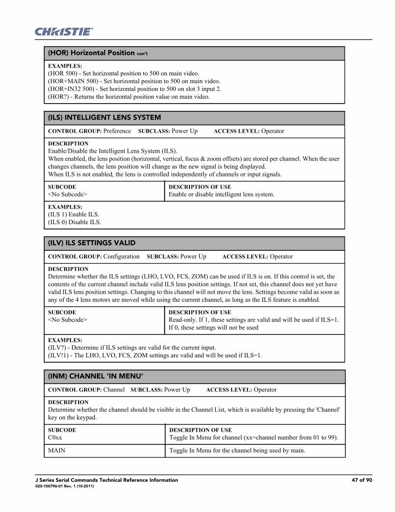
(HOR) Horizontal Position con’t
EXAMPLES:(HOR 500) - Set horizontal position to 500 on main video. (HOR+MAIN 500) - Set horizontal position to 500 on main video. (HOR+IN32 500) - Set horizontal position to 500 on slot 3 input 2. (HOR?) - Returns the horizontal position value on main video.
(ILS) INTELLIGENT LENS SYSTEM
CONTROL GROUP: Preference SUBCLASS: Power Up ACCESS LEVEL: Operator
DESCRIPTIONEnable/Disable the Intelligent Lens System (ILS). When enabled, the lens position (horizontal, vertical, focus & zoom offsets) are stored per channel. When the user changes channels, the lens position will change as the new signal is being displayed. When ILS is not enabled, the lens is controlled independently of channels or input signals.
SUBCODE<No Subcode>
DESCRIPTION OF USEEnable or disable intelligent lens system.
EXAMPLES:(ILS 1) Enable ILS. (ILS 0) Disable ILS.
(ILV) ILS SETTINGS VALID
CONTROL GROUP: Configuration SUBCLASS: Power Up ACCESS LEVEL: Operator
DESCRIPTIONDetermine whether the ILS settings (LHO, LVO, FCS, ZOM) can be used if ILS is on. If this control is set, the contents of the current channel include valid ILS lens position settings. If not set, this channel does not yet have valid ILS lens position settings. Changing to this channel will not move the lens. Settings become valid as soon as any of the 4 lens motors are moved while using the current channel, as long as the ILS feature is enabled.
SUBCODE<No Subcode>
DESCRIPTION OF USERead-only. If 1, these settings are valid and will be used if ILS=1. If 0, these settings will not be used
EXAMPLES:(ILV?) - Determine if ILS settings are valid for the current input. (ILV!1) - The LHO, LVO, FCS, ZOM settings are valid and will be used if ILS=1.
(INM) CHANNEL ‘IN MENU’
CONTROL GROUP: Channel SUBCLASS: Power Up ACCESS LEVEL: Operator
DESCRIPTIONDetermine whether the channel should be visible in the Channel List, which is available by pressing the 'Channel' key on the keypad.
SUBCODEC0xx
DESCRIPTION OF USEToggle In Menu for channel (xx=channel number from 01 to 99).
MAIN Toggle In Menu for the channel being used by main.
J Series Serial Commands Technical Reference Information 47 of 90020-100796-01 Rev. 1 (10-2011)

(INM) Channel ‘In Menu’ con’t
PIIP or SECD Toggle In Menu for the channel being used by PIP or Secondary.
EXAMPLES:(INM?) - Get channel in-menu state for channel used by main. (INM+MAIN?) - Get channel in-menu state for channel used by main. (INM+PIIP?) - Get channel in-menu state for channel used by PIP. (INM 1) - Show in-menu for the channel being used by main. (INM+PIIP 1) - Show in-menu for the channel being used by PIP. (INM+MAIN 0) - Hide in-menu for the channel being used by main. (INM+C001 0) - Hide in-menu for channel 1.
(ITG) TEST PATTERN GREY
CONTROL GROUP: Unsaved SUBCLASS: Power Up ACCESS LEVEL: Operator
DESCRIPTIONSpecify the grey level to use for the 'Grey' flat field internal test pattern. Range 0-1023. The level defaults to 512 on power up.
SUBCODE<No Subcode>
DESCRIPTION OF USESet grey level.
EXAMPLE:(ITG 512) - Set test pattern grey to mid point.
(ITP) INTERNAL TEST PATTERN
CONTROL GROUP: Unsaved SUBCLASS: Power Up ACCESS LEVEL: Operator
DESCRIPTION
Puts a test pattern on the screen or queries the test pattern currently displayed. Select which test pattern to display from the list: 0 = Off 1 = Grid 2 = Grey Scale 16 3 = White 4 = Flat Grey 5 = Black 6 = Checker 7 = 13 Point 8 = Color Bars 11 = Aspect Ratio 12 = Edge Blend 14 = Boresight
SUBCODE<No Subcode>
DESCRIPTION OF USEEnable, disable or change standard test patterns.
48 of 90 J Series Serial Commands Technical Reference Information020-100796-01 Rev. 1 (10-2011)

(ITP) Internal Test Pattern con’t
EXAMPLES:(ITP 0) - Disable test patterns - revert to previous input signal. (ITP 1) - Set test pattern to the grid pattern.
(KEN) KEYPAD IR SENSOR DISABLE
CONTROL GROUP: Preference SUBCLASS: Power Down ACCESS LEVEL: Operator
DESCRIPTIONEnable or disable the IR or wired keypad sensors. You cannot disable the keypad that is currently being used.
SUBCODEFRNT
DESCRIPTION OF USESet to 1 to enable the front IR keypad sensor, 0 to disable.
REAR Set to 1 to enable the rear IR keypad sensor, 0 to disable.
WIRE Set to 1 to enable the wired keypad jack, 0 to disable.
EXAMPLES:(KEN+REAR 1) - Enable rear IR sensor. (KEN+FRNT 0) - Disable front IR sensor. (KEN+WIRE?) - Get current wired jack enabled state.
(KEY) KEY MODE EMULATION
CONTROL GROUP: Unsaved SUBCLASS: Power Down ACCESS LEVEL: Operator
DESCRIPTIONUse Key Codes to emulate button presses on the IR or wired keypads.
SUBCODE<No Subcode>
DESCRIPTION OF USESpecify value of key to be emulated.
EXAMPLES:(KEY 46) - Send the Power key (down/press). (KEY 174) - Send the Power key (up/release). (KEY?) - View the last emulated key that was sent.
(LBL) LEFT BLANKING
CONTROL GROUP: Input SUBCLASS: Power Up ACCESS LEVEL: Operator
DESCRIPTIONSet the number of lines to blank (turn to black) at the left of the image. This can be used to blank out any unwanted data near the left edge of the image. A positive amount of blanking makes the image smaller. A negative amount of blanking makes the image larger. Negative blanking is only applicable to analog signals, when the autosetup has not been able to set the image size correctly. It is preferable not to use negative blanking, but to run autosetup again, ensuring that the content has active pixels on each edge of the image. The maximum amount of left blanking allowed is half the image width minus 10. For negative blanking, the image size can only be increased to the limit of the sync.
SUBCODEINxy
DESCRIPTION OF USESet the left blanking for slot x, input y.
J Series Serial Commands Technical Reference Information 49 of 90020-100796-01 Rev. 1 (10-2011)

(LBL) Left Blanking con’t
MAIN Set the left blanking for the main image.
PIIP or SECD Set the left blanking for the PIP or Secondary image.
EXAMPLES:(LBL 40) - Set left blanking to 40 on main video. (LBL+MAIN 40) - Set left blanking to 40 on main video. (LBL+PIIP 40) - Set left blanking to 40 on PIP video. (LBL+IN32 40) - Set left blanking to 40 on slot 3 input 2. (LBL?) - Returns the left blanking value on main video. (LBL+PIIP?) - Returns the left blanking value on PIP video. (LBL+IN12?) - Returns the left blanking value on slot 1 input 2.
(LCB) LENS SYSTEM CALIBRATION
CONTROL GROUP: Configuration/Preference/Unsaved SUBCLASS: Power Up ACCESS LEVEL: Opera-tor
DESCRIPTIONThis control calibrates the lens mount system for each of the 4 lens axes (horizontal, vertical, zoom and focus) to determine home positions, the motor travel ranges, and the motor backlash values. The Lens Calibration proce-dure is needed for all new lenses in order for the ILS feature to perform reliably. This control can also reset the lens to horizontal or vertical home positions, and configure if a reset or calibration routine should be run automat-ically on power up or lens insertion.
SUBCODE <No Subcode>
DESCRIPTION OF USERun calibration on all 4 lens motors (no param required).
HORZ Run calibration on Horizontal motor.
VERT Run calibration on Vertical motor.
FOCS Run calibration on Focus motor.
ZOOM Run calibration on Zoom motor.
HOME Return the lens to the horizontal and vertical home position. Focus and zoom are unaffected.
APWR Enable automatic lens reset on system power-up (checkbox). This is recommended to ensure maximum positional accuracy for the ILS feature, particularly if the lens is subject to manual movement between power sessions. This reset will only take place if the ILS feature is enabled.
ANEW Enable automatic lens calibration when a new lens is inserted (checkbox). This is highly recommended since different lenses have different characteristics.
STAT Get the current status for lens motor calibration.
LNID Get the lens ID.
50 of 90 J Series Serial Commands Technical Reference Information020-100796-01 Rev. 1 (10-2011)

(LCB) Lens System Calibration con’t
MNZF Enable manual zoom/focus control. When set the zoom and focus motors are de-energized and will not be under the control of ILS. Zoom and focus will be adjustable by hand. If not set, all lens motors will be under ILS control and users should not attempt to adjust manually, as this will damage the motors.
LOCK Lock all lens motors, preventing the lens from moving. This overrides all other lens functions.
EXAMPLES:
(LCB) - Calibrate all motors (LCB+STAT?) - Get the current status for lens motor calibration. (LCB+HOME) - Reset H & V motors to their optical home position. (LCB+APWR 1) - Enable Auto Lens Reset on Power-Up. (LCB+ANEW 0) - Disable Auto Lens Calibration on lens insertion. (LCB+ANEW?) - Get state of Auto Lens Calibration. (LCB+LOCK1) - Lock all lens motors in their current positions.(LCB+MNZF 1) - Set manual zoom/focus mode. You can adjust the motors by hand now. (LCB+MNZF 0) - Re-energize zoom/focus motors. The motors will automatically re-locate the center flag and stay at their center position.
(LCD) LCD BACKLIGHT
CONTROL GROUP: Preference SUBCLASS: Power Down ACCESS LEVEL: Operator
DESCRIPTIONControls the backlight options for the LCD Keypad. Backlight time-out length, backlight intensity (brightness) and forcing backlight to stay off.
SUBCODEKEEP
DESCRIPTION OF USE0 - backlight always on, 1 - backlight always off, 2 - timer (see examples).
LEVL (0-25) - Backlight Intensity Level (brightness). 0 for off, 25 for max.
TIME (5 - 600) - Time in seconds the backlight will remain on after a key is pressed.
EXAMPLES:(LCD+TIME 5) - 5 seconds after a key is pressed on the keypad, the backlight will go off. (LCD+TIME 600) - 10 minutes after a key is pressed on the keypad, the backlight will go off. (LCD+KEEP 0) - Backlight will always stay on. (LCD+KEEP 1) - Backlight will always stay off. (LCD+KEEP 2) - Backlight will stay on for the number of seconds set in LCD+TIME. The backlight will always stay on if an alarm is raised or if you are on the lcd test screen. (LCD+LEVL 25) - Maximum lcd backlight brightness. (LCD+LEVL 10) - Low lcd backlight brightness.
J Series Serial Commands Technical Reference Information 51 of 90020-100796-01 Rev. 1 (10-2011)

(LDT) LEVEL DETECTOR
CONTROL GROUP: Unsaved SUBCLASS: Power Up ACCESS LEVEL: Operator
DESCRIPTIONThis Level Detector control changes the gamma table settings to make it easy for the user to adjust the input lev-els. It causes the data to be processed so that all levels below a specified value are set to black (0) and all above and including it are set to white (1024). This control takes place before the scaler/deinterlacer.
SUBCODE<No Subcode>
DESCRIPTION OF USEEnable or disable level detector.
EXAMPLES:(LDT 1) - Turn on level detector. (LDT 0) - Turn off level detector.
(LDV) LEVEL DETECTOR VALUE
CONTROL GROUP: Unsaved SUBCLASS: Power Up ACCESS LEVEL: Operator
DESCRIPTIONThe Level Value control specifies the value to be used by the level detector. The range is 1-1023. This control takes place before the scaler/deinterlacer.
SUBCODE<No Subcode>
DESCRIPTION OF USESet level detector valve.
EXAMPLE:(LDV 500) - Set level detector to 500. All data greater than or equal to 500 will be shown in the image.
(LHO) LENS HORIZONTAL POSITION ADJUSTMENT
CONTROL GROUP: Configuration SUBCLASS: Power Up ACCESS LEVEL: Operator
DESCRIPTIONAdjust the lens to a specific horizontal position. This control moves the image horizontally by moving the whole display area. This is different from the 'Position' control which moves the image electronically within a fixed display area.
SUBCODE<No Subcode>
DESCRIPTION OF USEMove the lens mount to a specified horizontal position. The default data range is -2050 to 2050.
EXAMPLE:(LHO 500) - Move lens mount to position 500 on the horizontal axis.
52 of 90 J Series Serial Commands Technical Reference Information020-100796-01 Rev. 1 (10-2011)

(LLC) LITELOC CALIBRATION
CONTROL GROUP: Preference SUBCLASS: Power Up ACCESS LEVEL: Service
DESCRIPTIONCalibrate the LiteLoc sensor. This control will be disabled until the projector is ready to be calibrated, so the fol-lowing conditions must be met first:
i) The projector must have Dual lamps on.ii) The lamps must have warmed up for at least 5 minutes.
The calibration will take approximately 1 1/2 minutes to complete. The shutter will be closed for the duration of the calibration, and will open again when the calibration is complete.“Constant Intensity” mode cannot be used if the LiteLoc sensor has not been calibrated.
SUBCODE<No Subcode>
DESCRIPTION OF USECalibrate the sensor.
EXAMPLE:(LLC) - Initiate the calibration cycle.
(LMV) ADJUST LENS POSITION/LENS MOVE
CONTROL GROUP: Unsaved SUBCLASS: Power Up ACCESS LEVEL: Operator
DESCRIPTIONAdjust all 4 lens motors simultaneously, or move any lens motor arbitrarily (i.e. move motor indefinitely, rather than to some absolute position).
SUBCODE<No Subcode>
DESCRIPTION OF USEMove all lens motors with (LMV h v z f) where h, v, z, f represent the horizontal, vertical, zoom and focus position information.
HSTP Move the horizontal lens motor a relative # steps.
VSTP Move the vertical lens motor a relative # steps.
FSTP Move the focus lens motor a relative # steps.
ZSTP Move the zoom lens motor a relative # steps.
HRUN Start/stop/reverse the horizontal lens motor.
VRUN Start/stop/reverse the vertical lens motor.
FRUN Start/stop/reverse the focus lens motor.
ZRUN Start/stop/reverse the zoom lens motor.
EXAMPLES:(LMV 1000 1500 500 -500) - Set the lens to H:1000, V:1500, Z:500, F:-500(LMV+HRUN1) - Start to move horizontal motor toward positive max position(LMV+VRUN0) - Stop the vertical motor.(LMV+ZRUN-1) - Start to move horizontal motor toward negative max position(LMV+HSTP45) - Move the horizontal motor 45 steps in the positive direction(LMV+ZSTP-300) - Move the zoom motor 300 steps in the negative direction
J Series Serial Commands Technical Reference Information 53 of 90020-100796-01 Rev. 1 (10-2011)

(LOC) LOCAL SETTINGS
CONTROL GROUP: Preference SUBCLASS: Power Down ACCESS LEVEL: Advanced
DESCRIPTIONSet the localization options such as Language and display options for temperature units.
SUBCODELANG
DESCRIPTION OF USESet the system language:0 - English1 - French2 - German3 - Spanish4 - Italian5 - Chinese6 - Japanese7 - Korean
TEMP Set the temperature units. 0 - Celsius1 - Fahrenheit
EXAMPLES:(LOC+TIME 1) - Set timezone to standard 12 hour.(LOC+TIME?l) - Get list of formats. (LOC+TIME?)(LOC+TIME!001) - Get time format.
(LOS) LOOP OUT SOURCE SELECTION
CONTROL GROUP: Preference SUBCLASS: Power Up ACCESS LEVEL: Operator
DESCRIPTIONThis control is used to configure the HDMI output options and selects the loop out source for the transmitters of the THIC card. Selecting 'Direct Loop' will directly pass-through the HDMI input signals: on the same Twin HDMI Input Card, the Input1 signal is looped to Output1 and the Input2 signal is looped to Output2. Selecting 'Main/PIP Loop' will loop the Main & PIP video to the outputs, regardless from which card these signals origi-nate. The Main video signal is looped to Output1 and the PIP video signal is looped to Output2. Selecting 'Dis-able' will shut off the HDMI outputs completely.
SUBCODE<No Subcode>
DESCRIPTION OF USESet loop out source selection
EXAMPLES: (LOS 0) - Shut off loop out(LOS 1) - Set loop out source to be "local" on slot 1(LOS 2) - Set loop out source to be the "Main/PIP" images(LOS ?) - Get loop out source selection on slot 1
54 of 90 J Series Serial Commands Technical Reference Information020-100796-01 Rev. 1 (10-2011)

(LPI) LAMP INTENSITY
CONTROL GROUP: Preference SUBCLASS: Power Up ACCESS LEVEL: Operator
DESCRIPTIONAdjust the lamp intensity (% of full).
SUBCODE<No Subcode>
DESCRIPTION OF USESet lamp intensity.
EXAMPLE:(LPI 80) - Set the intensity set point to 80.
(LPL) LAMP LIFE
CONTROL GROUP: Saved SUBCLASS: Power Down ACCESS LEVEL: Operator
DESCRIPTIONSet the number of lamp hours of usage at which a warning must be given. When that number of hours is reached on either lamp, a warning message will be added to the status system indicating that the lamp should be changed. This is a user settleable limit only, and does not guarantee any number of hours for lamp life. This control has no bearing on lamp warranty and is not tied to actual lamp life in any way. The default is 0, which means that the fea-ture is off and no warning will be generated.
SUBCODE<No Subcode>
DESCRIPTION OF USESet the limit for the lamp hours warning.
EXAMPLES:(LPL 2000) - A system health warning will be displayed when the lamp has run for 2000 hours.(LPL 0) - Lamp life monitoring is not used.
(LPM) LAMP MODE
CONTROL GROUP: Preference SUBCLASS: Power Up ACCESS LEVEL: Operator
DESCRIPTIONSelects the lamp power control method, which determines how the lamp power and intensity are controlled. If 'Maximum Brightness', the lamp burns as brightly as possible. Select 'Intensity' mode to maintain a specific brightness level over time - as the lamp ages, the projector will increase power as needed to closely maintain the required output from the lamp. Select 'Power' to specify the power level supplied to the lamp. Both 'Intensity' and 'Power' modes allow you to extend lamp life. Valid values are: 0 = Maximum Brightness 1 = Constant Intensity 2 = Constant Power
SUBCODE<No Subcode>
DESCRIPTION OF USESet the lamp operation to be power, maximum, or intensity con-trolled.
EXAMPLE:(LPM 2) - Control lamp(s) with constant power.
J Series Serial Commands Technical Reference Information 55 of 90020-100796-01 Rev. 1 (10-2011)

(LPP) LAMP POWER
CONTROL GROUP: Preference SUBCLASS: Power Up ACCESS LEVEL: Operator
DESCRIPTIONSet the lamp power in Watts. This actually scales the power to lamp gain, the true control parameter. The Power control represents the amount of power sent to the lamps. Power increases when operating in Intensity mode, until it reaches its maximum. The value remains stable when in Max Brightness or Power mode. If using Power mode, setting a lower power level reduces brightness and extends lamp life.
SUBCODE<No Subcode>
DESCRIPTION OF USESet the Lamp power.
EXAMPLE:(LPP 300) - Sets lamp power to 300W.
(LVO) LENS VERTICAL OFFSET POSITION ADJUSTMENT
CONTROL GROUP: Configuration SUBCLASS: Power Up ACCESS LEVEL: Operator
DESCRIPTIONAdjust the lens to a specific vertical position. This control moves the image horizontally by moving the whole display area. This is different from the 'Position' control which moves the image electronically within a fixed display area.
SUBCODE<No Subcode>
DESCRIPTION OF USEMove the lens mount to a specified vertical position. The default data range is -2050 to 2050.
EXAMPLE:(LVO 500) - Move lens mount to position 500 on the vertical axis.
(MBE) MESSAGE BOX ENABLE
CONTROL GROUP: Preference SUBCLASS: Power Down ACCESS LEVEL: Operator
DESCRIPTIONThis control enables the displaying of groups of message boxes on the OSD.
SUBCODEAUTO
DESCRIPTION OF USEEnable or disable the pop-up of automatic message boxes. These are messages to the user that are not directly triggered by user actions. Examples are signal information, function limitation or auto calibration message boxes.
USER Enable or disable the pop-up of message boxes that are directly triggered by user actions. Examples are gamma or lens control message boxes.
3DST Enable or disable the pop-up of message boxes that are triggered by 3D setup errors.
56 of 90 J Series Serial Commands Technical Reference Information020-100796-01 Rev. 1 (10-2011)

(MBE) Message Box Enable con’t
EXAMPLES:(MBE+AUTO ?) - Get current auto message boxes enable state. (MBE+ AUTO 0) - Set auto message boxes to not be displayed.(MBE+AUTO 1) - Set auto message boxes to be displayed.(MBE +USER ?) - Get current user message boxes enable state.(MBE+USER 0) - Set user message boxes to not be displayed.(MBE+USER 1) - Set user message boxes to be displayed.
(MCS) MENU CASCADING ENABLE
CONTROL GROUP: Preference SUBCLASS: Power Down ACCESS LEVEL: Operator
DESCRIPTIONEnable or disable cascading menus. When disabled, a single menu level will be displayed at a time. NOTE: When Tiling is enabled, this function is not available, the menu is in a fixed position and is non-cascading.
SUBCODE<No Subcode>
DESCRIPTION OF USEEnable or disable cascading.
EXAMPLES:(MCS ?) - Get the current state of this setting. (MCS 0) - Disable cascading menus.(MCS 1) - Enable cascading menus.
(MDE) SERIAL MODE
CONTROL GROUP: Preference SUBCLASS: Power Down ACCESS LEVEL: Advanced
DESCRIPTIONSet the mode for a serial communications port. Settings such as bits, parity and stop bits are grouped together into one selection.
SUBCODEPRTA
DESCRIPTION OF USESet the mode on port A (RS232 In).
PRTB Set the mode on port B (RS232 Out).
PRTC Set the mode on port C (RS422).
EXAMPLES:(MDE+PRTA "8N1") - Set mode on port A to 8-bit, no parity, 1 stop bit.(MDE+PRTA "7E1") - Set mode on port A to 7-bit, even parity, 1 stop bit. (MDE+PRTA "7O1") - Set mode on port A to 7-bit, odd parity, 1 stop bit. (MDE+PRTA?) - Get mode (MDE+PRTA!"8N1").
(MFT) MENU FONT
CONTROL GROUP: Preference SUBCLASS: Power Down ACCESS LEVEL: Operator
DESCRIPTIONSet the font size used by OSD.
J Series Serial Commands Technical Reference Information 57 of 90020-100796-01 Rev. 1 (10-2011)

(MFT) Menu Font con’t
SUBCODE<No Subcode>
DESCRIPTION OF USEView/Set Choose large font or small font as the font used by OSD.
EXAMPLES:(MFT ?) - Get current font option used by the OSD. 0 is small font, 1 is large font. (MFT 1) - Use large font as the OSD font.
(MLK) CHANNEL MEMORY LOCK
CONTROL GROUP: Channel SUBCLASS: Power Up ACCESS LEVEL: Operator
DESCRIPTIONLock a channel from being edited.
SUBCODEC0xx
DESCRIPTION OF USELock channel (xx=channel number from 01 to 99).
MAIN Lock the channel being used by main.
PIIP or SECD Lock the channel being used by PIP or Secondary.
EXAMPLES:(MLK?) - get channel locked state for channel used by main. (MLK+MAIN?) - Get channel locked state for channel used by main. (MLK+PIIP?) - Get channel locked state for channel used by PIP. (MLK 1) - Lock the channel being used by main. (MLK+PIIP 1) - Lock the channel being used by PIP. (MLK+MAIN 0) - Unlock the channel being used by main. (MLK+C001 0) - Unlock channel 1.
(MNR) MOSQUITO NOISE REDUCTION
CONTROL GROUP: Input SUBCLASS: Power Up ACCESS LEVEL: Operator
DESCRIPTIONMosquito Noise Reduction (MNR) dynamically adapts to image content, effectively reducing mosquito artifacts around sharp edges in DCT based compression.
SUBCODEINxy
DESCRIPTION OF USESet the mosquito noise reduction for slot x, input y.
MAIN Set the mosquito noise reduction for main video.
PIIP or SECD Set the mosquito noise reduction for PIP or Secondary video.
EXAMPLE:(NRB 32) - Set the mosquito noise reduction to mid point for main video.
58 of 90 J Series Serial Commands Technical Reference Information020-100796-01 Rev. 1 (10-2011)

(MNU) MENU SETTINGS AND CONFIGURATION
CONTROL GROUP: Preference SUBCLASS: Power Down ACCESS LEVEL: Operator
DESCRIPTIONSet menu type, view OSD state, read menu structure.
SUBCODE<No Subcode>
DESCRIPTION OF USEView/change the current state of the OSD (0=presentation, 1=main, 2=submenu).
EXAMPLE:(MNU?)(MNU!0)
(MSH) MENU SHIFT HORIZONTAL
CONTROL GROUP: Preference SUBCLASS: Power Up ACCESS LEVEL: Operator
DESCRIPTIONChange the horizontal position of the main menu. If the position is not from one of the preset positions, MSP will be changed to custom.
SUBCODE<No Subcode>
DESCRIPTION OF USEView/set the horizontal position of the main menu.
EXAMPLES:(MSH ?) - Get current horizontal position of main menu. (MSH 50) - Set main menu horizontal position to 50 pixels from left edge.
(MSP) MENU LOCATION
CONTROL GROUP: Preference SUBCLASS: Power Up ACCESS LEVEL: Operator
DESCRIPTIONSet the default menu position on the screen. Valid options are: 0 = 4:3 TopLeft 1 = 4:3 Inset 1 2 = 4:3 Inset 2 3 = 16:9 TopLeft 4 = 16:9 Inset 1 5 = 16:9 Inset 2 NOTE: When Tiling is enabled, this function is not available, the menu is in a fixed position (top-left) and is non-cascading.
SUBCODE<No Subcode>
DESCRIPTION OF USEView/set the preset menu position.
EXAMPLES:(MSP ?) Get current menu position preset. (MSP 0) Set main menu position to 4:3 TopLeft, the top left corner of screen.
J Series Serial Commands Technical Reference Information 59 of 90020-100796-01 Rev. 1 (10-2011)

(MSV) MENU SHIFT VERTICAL
CONTROL GROUP: Preference SUBCLASS: Power Up ACCESS LEVEL: Operator
DESCRIPTIONChange the vertical position of the main menu. If the position is not from one of the preset positions, MSP will be changed to custom.
SUBCODE<No Subcode>
DESCRIPTION OF USEView/set the vertical position of main menu.
EXAMPLES:(MSV ?) - Get current vertical position of main menu. (MSV 50) - Set main menu vertical position to 50 pixels from top edge.
(NAM) CHANNEL NAME
CONTROL GROUP: Channel SUBCLASS: Power Up ACCESS LEVEL: Operator
DESCRIPTIONChannel Name is optional text assigned to a channel and can appear in the Channel Setup menu, Channel Edit menu, the channel list and the Status menu.
SUBCODEC0xx
DESCRIPTION OF USESet the channel name for the channel (xx=channel number from 01 to 99).
MAIN Set the channel name for the channel being used by main.
PIIP or SECD Set the channel name for the channel being used by PIP or Second-ary.
EXAMPLES:(NAM?) - Get current active channel name for main video. (NAM+MAIN?) - Get channel name being used by main. (NAM+PIIP?) - Get channel name being used by PIP. (NAM "Test") - Set channel name being used by main to 'Test'. (NAM+PIIP "Test") - Set channel name being used by PIP to 'Test'. (NAM+MAIN "Test") - Set channel name being used by main to 'Test'. (NAM+C001 "Test") - Set channel name for channel 1 to 'Test.'
(NET) NETWORK SETUP
CONTROL GROUP: Config/Preference SUBCLASS: Power Down ACCESS LEVEL: Admin
DESCRIPTION
Set or request the network setup for this device.
SUBCODEDOMA
DESCRIPTION OF USESet the domain name
ETH0 Set the IP address for the first ethernet controller.
GATE Set the network gateway.
60 of 90 J Series Serial Commands Technical Reference Information020-100796-01 Rev. 1 (10-2011)

(NET) Network Setup con’t
HOST Set the host name.
MAC0 Gets the MAC address of the first ethernet controller.
PORT Set the PORT number.
SUB0 Set the network subnet mask for the first ethernet controller.
EXAMPLES:(NET+ETH0 "192.168.1.35") - Set new IP address on the first ethernet controller. (NET+GATE "192.168.0.1") - Set the gateway. (NET+SUB0 "255.255.255.0") - Set the subnet mask on the first ethernet controller. (NET+HOST "MyHostName") - Set the host name. (NET+DOMA "MyDomainName") - Set the domain name. (NET+ETH0 ?) - Retrieve IP address from first controller. (NET+ETH0! 192.168.1.35). (NET+ETH0 ?) - Retrieve IP address from second controller. (NET+ETH1! 192.168.1.36). (NET+MAC0 ?) - Retrieve MAC address from first controller. (NET+MAC0! 00:12:3F:7B:76:B4). (NET+GATE ?) - Retrieve default gateway. (NET+GATE! 192.168.0.1). (NET+PORT "3002") - Set the Port number.(NET+PORT ?) - Retrieve the Port number. (NET+PORT! 3002).
(NRB) BLOCK ARTIFACT REDUCTION
CONTROL GROUP: Input SUBCLASS: Power Up ACCESS LEVEL: Operator
DESCRIPTIONBlock Artifact Reduction (BAR) locates and reduces block edges produced by discrete cosine transform (DCT) based compression processing.
SUBCODEINxy
DESCRIPTION OF USESet the BAR for slot x, input y.
MAIN Set the BAR for main video.
PIIP or SECD Set the BAR for PIP or Secondary video.
EXAMPLE:(NRB 32) - Set the BAR to mid point for main video.
(NRD) GENERAL NOISE REDUCTION
CONTROL GROUP: Input SUBCLASS: Power Up ACCESS LEVEL: Operator
DESCRIPTIONAdaptive general noise reduction selects a filter sensitivity to noise. A higher value may improve noisy sources, although it will soften the image.
SUBCODEINxy
DESCRIPTION OF USESet the noise reduction for slot x, input y.
MAIN Set the noise reduction for main video.
PIIP or SECD Set the noise reduction for PIP or Secondary video.
J Series Serial Commands Technical Reference Information 61 of 90020-100796-01 Rev. 1 (10-2011)

(NRD) General Noise Reduction con’t
EXAMPLE:(NRD 32) - Set the noise reduction to mid point for main video.
(NTR) NETWORK ROUTING
CONTROL GROUP: Preference SUBCLASS: Power Down ACCESS LEVEL: Operator
DESCRIPTIONSet routing for ASCII messages.
SUBCODE<No Subcode>
DESCRIPTION OF USEUsed to enable or disable daisy chaining.0 = RS232, RS422 & Ethernet communications are all separate from one another1 = RS422 port(s) is/are connected to the RS232 network2 = The Ethernet port is connected to the RS232 network3 = RS232, RS422 & Ethernet are all connected to each other
EXAMPLES:(NTR?l) - List routing options. (NTR 0) - Each connection is routed separately. (NTR 3) - Full daisy-chaining.
(OPP) ODD PIXEL PHASE
CONTROL GROUP: Option SUBCLASS: Power Up ACCESS LEVEL: Operator
DESCRIPTIONAdds an offset to the pixel phase setting on this card. It is used to compensate for differences between the A to D converter used to sample even pixels, and the one used for odd pixels. A value of 0 is the null position in which both A and D converters are set to exactly the same value.
SUBCODESLx0
DESCRIPTION OF USESet a pixel phase offset for the second A to D.
EXAMPLE:(OPP+SL10 -1) - Set a pixel phase offset to -1 on slot 1.
(OSD) ON SCREEN DISPLAY
CONTROL GROUP: Unsaved SUBCLASS: Power Down ACCESS LEVEL: Operator
DESCRIPTIONDisplay or Hide the OSD screen.
SUBCODE<No Subcode>
DESCRIPTION OF USETurn on/off OSD display.
EXAMPLES:(OSD ?) - Get current state of OSD. 0 when OSD is hidden, 1 when OSD is displayed. (OSD 0) - Turn off OSD display. The OSD will run in the background, even though it is not visible.
62 of 90 J Series Serial Commands Technical Reference Information020-100796-01 Rev. 1 (10-2011)

(OST) OSD TRANSPARENCY
CONTROL GROUP: Preference SUBCLASS: Power Up ACCESS LEVEL: Operator
DESCRIPTIONEnable or Disable on screen display transparency.
SUBCODE<No Subcode>
DESCRIPTION OF USEEnable or disable OSD transparency.
EXAMPLE:(OST 1) - Enable OSD transparency.
(PBC) PIP BORDER COLOR
CONTROL GROUP: Preference SUBCLASS: Power Up ACCESS LEVEL: Operator
DESCRIPTIONThis control lets you choose the color of the optional border around the picture-in-picture image. The border can be disabled by setting the border width PBW to zero. Valid options are: 0 = Black 1 = Dark Red 2 = Dark Green 3 = Dark Yellow 4 = Dark Blue 5 = Dark Magenta 6 = Dark Cyan 7 = Dark Grey 8 = Light Grey 9 = Red 10 = Green 11 = Yellow 12 = Blue 13 = Magenta 14 = Cyan 15 = White
SUBCODE<No Subcode>
DESCRIPTION OF USE Select border color for PIP window.
EXAMPLE:(PBC 0) - Select black PIP border.
(PBW) PIP BORDER WIDTH
CONTROL GROUP: Preference SUBCLASS: Power Up ACCESS LEVEL: Operator
DESCRIPTIONSelects whether a border should be placed around the PIP window. Setting the width to zero (0) will remove the border. Setting it to 1 will enable the border.
SUBCODE<No Subcode>
DESCRIPTION OF USESelect border width for PIP window.
EXAMPLE:(PBW 10) - Select PIP border width of 10.
J Series Serial Commands Technical Reference Information 63 of 90020-100796-01 Rev. 1 (10-2011)

(PDT) PEAK DETECTOR
CONTROL GROUP: Unsaved SUBCLASS: Power Up ACCESS LEVEL: Operator
DESCRIPTIONEnables or disables the peak detector test mode. This is used to aid in setup of input levels. For each color, pixel values very near black will be displayed black, pixel values very near peak level will be displayed full on. All oth-ers will be displayed in mid level grey. Input levels for each color should be adjusted so that black pixels in the image just turn black, and full on pixels just turn full on. When adjustment is completed this control should be disabled to allow display of all grey levels. This control takes place before the scaler/deinterlacer.
SUBCODE<No Subcode>
DESCRIPTION OF USEEnable or disable peak detector.
EXAMPLES:(PDT 1) - Turn on peak detector. (PDT 0) - Turn off peak detector.
(PHP) PIP HORIZONTAL POSITION
CONTROL GROUP: Preference SUBCLASS: Power Up ACCESS LEVEL: Operator
DESCRIPTIONSets the horizontal position of the PIP window. Specifies where to place the center of the PIP window horizon-tally on the panel in pixels.
SUBCODE<No Subcode>
DESCRIPTION OF USESet PIP horizontal position.
EXAMPLES:(PHP 100) - Set PIP horizontal position to 100 pixels. (PHP?)(PHP!100) - Get PIP horizontal position.
(PHS) PIP HORIZONTAL SIZE
CONTROL GROUP: Preference SUBCLASS: Power Up ACCESS LEVEL: Operator
DESCRIPTIONSets the size (width) of the PIP window in pixels. The active portion of the input signal, as determined by blank-ing controls, will be scaled to fit into the PIP window. The height of the PIP window will be set to maintain the aspect ratio of the image being captured, as determined by the vertical stretch control.
SUBCODE<No Subcode>
DESCRIPTION OF USESet PIP horizontal size.
EXAMPLES:(PHS 100) - Set PIP size to 100 pixels. (PHS?)(PHS!100) - Get PIP size.
64 of 90 J Series Serial Commands Technical Reference Information020-100796-01 Rev. 1 (10-2011)

(PIP) PICTURE IN PICTURE
CONTROL GROUP: Preference SUBCLASS: Power Up ACCESS LEVEL: Operator
DESCRIPTIONThis control enables or disables 'Picture in Picture' (PIP) mode. When this control is enabled for the first time, the first valid video signal starting at slot 1 input 1 is routed to the PIP window. If no signals are present, the first available slot/input combination is selected. PIP and image transition effects (seamless switching) both require resources to configure a second image process-ing path. Therefore these two features cannot be active at the same time.
SUBCODE<No Subcode>
DESCRIPTION OF USEEnable or disable PIP window.
EXAMPLES:(PIP 0) - Disables PIP video. (PIP 1) - Enables PIP video. (PIP 2) - Enables PBP video (picture-by-picture)(PIP ?) - Returns the state of the PIP control. i.e. (PIP! 1) - PIP enabled.
(PJH) PROJECTOR HOURS
CONTROL GROUP: Unsaved SUBCLASS: Power Down ACCESS LEVEL: Operator
DESCRIPTIONReports the number of hours elapsed on the projector. This control is read-only.
SUBCODE<No Subcode>
DESCRIPTION OF USERead projector hours.
EXAMPLE:(PJH ?) - Returns hours elapsed on projector.
(PLK) USER LOCKOUTS
CONTROL GROUP: Preference SUBCLASS: Power Down ACCESS LEVEL: Admin
DESCRIPTIONUser lockouts provide a way to lock various controls in the system, protecting them against accidental or unwanted user adjustment.
SUBCODE<No Subcode>
DESCRIPTION OF USESet/get a sequence of codes/subcodes that are locked out from user adjustment.
ENBL Set the master enabled switch - when unselected, user locks are ignored.
J Series Serial Commands Technical Reference Information 65 of 90020-100796-01 Rev. 1 (10-2011)

(PLK) PIP User Lockouts con’t
EXAMPLES:(PLK L"*") - Locks all codes/subcodes in the system (except the PLK and PWR control, which are unlockable) (PLK U"*") - Unlocks all codes/subcodes in the system, regardless of which method was used to lock them (PLK L"SIN*") - Locks all subcodes within the SIN control (PLK U"SIN+PIIP") - Following the previous example, this unlocks SIN+PIIP, leaving all other SIN subcodes locked (PLK L"SIN*" L"GAM") - Locks all SIN subcodes, and locks the GAM code (PLK?)(PLK!L"SIN*" L"GAM") - Returns the list of user lockouts
(PMT) PICTURE MUTE
CONTROL GROUP: Unsaved SUBCLASS: Power Up ACCESS LEVEL: Operator
DESCRIPTIONMutes the displayed image (image goes black) without closing the mechanical shutter. When the image is muted, all DMD mirrors will be turned to the off position.
SUBCODE<No Subcode>
DESCRIPTION OF USEMute/Unmute the image.
EXAMPLES:(PMT 1) - Mutes the picture. (PMT 0) - Unmutes the picture.
(PNG) PING
CONTROL GROUP: Configuration SUBCLASS: Power Down ACCESS LEVEL: Status
DESCRIPTION
This command returns basic projector information to the user which includes the type of device & main software version. Note that some devices have multiple CPUs each with its own software version. Only the software version of what is considered to be the master CPU, is returned here. The return parameters are: Type, Major, Minor, Beta. The beta value is optional meaning it is an engineering build and has not been validated. Note: List of devices: 40 = ACT, 41 = Cinema, 42 = CinemaMini, 43 = Media Block, 44 = M Series, 46 = J Series
SUBCODE<No Subcode>
DESCRIPTION OF USERead projector information.
EXAMPLE:(PNG?)(PNG!41 001 000 234) - Indicates 'Cinema' type, software: 1 major, 0 minor, 234 beta.
66 of 90 J Series Serial Commands Technical Reference Information020-100796-01 Rev. 1 (10-2011)

(PPA) POSITION PRESET ASPECT
CONTROL GROUP: Preference SUBCLASS: Power Down ACCESS LEVEL: Operator
DESCRIPTIONWhen enabled, this control ensures that during auto setup for any source, its aspect ratio is maintained when its default size is calculated. This is similar to cases where a stretch is defined for a source in the lookup table. If dis-abled and no stretch is defined, the source is scaled to fit the screen.
SUBCODE<No Subcode>
DESCRIPTION OF USEMaintain or do not maintain aspect during auto setup.
EXAMPLES:(PPA 0) - Disables maintain aspect during auto setup. (PPA 1) - Enables maintain aspect during auto setup.
(PPP) PIP POSITION PRESET
CONTROL GROUP: Preference SUBCLASS: Power Up ACCESS LEVEL: Operator
DESCRIPTIONChoose a preset location and size for the PIP window. The Location settings will adjust the size and position of the window. Blanking will not be affected. While in split screen mode, several channel controls that resize image will be disabled. These controls are size, H-Position and V-Position. Valid values are: 0 = Top Right 1 = Top Left 2 = Bottom Left 3 = Bottom Right
SUBCODE<No Subcode>
DESCRIPTION OF USESelect PIP window location.
EXAMPLE:(PPP 0) - Select top left preset position.
(PPS) PIP SWAP
CONTROL GROUP: Preference SUBCLASS: Power Up ACCESS LEVEL: Operator
DESCRIPTIONThis control swaps the current main and PIP inputs. It will swap the inputs regardless if there are valid signals on either of the inputs.
SUBCODE<No Subcode>
DESCRIPTION OF USESwap Main and PIP input.
EXAMPLE:(PPS) - Swap inputs.
J Series Serial Commands Technical Reference Information 67 of 90020-100796-01 Rev. 1 (10-2011)

(PRT) SERIAL PORT
CONTROL GROUP: Preference SUBCLASS: Power Down ACCESS LEVEL: Status
DESCRIPTIONGet a list of serial ports available on the device.
SUBCODE<No Subcode>
DESCRIPTION OF USERead serial ports.
EXAMPLE:(PRT?1) - Get list of ports.
(PTL) SERIAL PROTOCOL
CONTROL GROUP: Preference SUBCLASS: Power Down ACCESS LEVEL: Advanced
DESCRIPTIONSet the protocol for a serial communications port.
SUBCODEPRTA
DESCRIPTION OF USESet the protocol on port A (RS232 In) pass through
PRTB Set the protocol on port B (RS232 Out).
PRTC Set the protocol on port C (RS422).
EXAMPLES:(PTL+PRTA "RAW") - Set protocol on port A to a pass through raw data protocol. (PTL+PRTA "CHRISTIE") - Set protocol on port A to a Christie Digital serial protocol. (PTL+PRTA?) - Get protocol (PTL+PRTA!"RAW").
(PVP) PIP VERTICAL POSITION
CONTROL GROUP: Preference SUBCLASS: Power Up ACCESS LEVEL: Operator
DESCRIPTIONSets the vertical position of the PIP window. Specifies where to place the center of the PIP window vertically on the panel in pixels.
SUBCODE<No Subcode>
DESCRIPTION OF USESet vertical position of PIP window.
EXAMPLES:(PVP 100) - Set PIP vertical position to 100 pixels. (PVP?)(PVP!100) - Get PIP vertical position.
68 of 90 J Series Serial Commands Technical Reference Information020-100796-01 Rev. 1 (10-2011)

(PWR) POWER
CONTROL GROUP: Unsaved SUBCLASS: Power Down ACCESS LEVEL: Operator
DESCRIPTIONChange the power state of the projector.
Possible values:0 = Power-Off (to Standby mode)1 = Power-On (to Lamps On mode)10 = Cooldown lamp is cooling down. Controlled by lamp (read-only)11 = Warmup lamp is warming up. Controlled by lamp (read-only)20 = AutoShutdown mode 1 (read only)21 = AutoShutdown mode 2 (read only)22 = AutoShutdown mode 3 (read only)23 = Emergency Shutdown, ending in Power Off
SUBCODERBFS
DESCRIPTION OF USEReboots the projector into failsafe mode. The projector must be in Standby mode before initiating this command
EXAMPLES:(PWR?) - Get projector power status. (PWR1) - Turn the lamp and all electrical power on. (PWR0) - Set the projector to standby mode.(PWR+RBFS 1) - Reboot into failsafe mode.
(PXP) PIXEL PHASE
CONTROL GROUP: Input SUBCLASS: Power Up ACCESS LEVEL: Operator
DESCRIPTIONPixel Phase adjusts the phase of the pixel sampling clock relative to the incoming signal. This allows you to fine tune the sampling point within one pixel. Adjust the Pixel Phase when the image (usually from an RGB source) shows shimmer. Note that if the shimmer is concentrated in vertical bands with little or no shimmer between the bands, then it is likely that Pixel Tracking needs adjustment. Pixel Tracking must be set correctly before adjusting Pixel Phase. Pixel Phase can only be set on Analog input cards. The range is 0-31.
SUBCODEINxy
DESCRIPTION OF USESet the pixel phase for slot x, input y.
MAIN Set the pixel phase for the main image.
PIIP or SECD Set the pixel phase for the PIP or Secondary image.
EXAMPLES:(PXP 16) - Set pixel phase to 16 on main video. (PXP+MAIN 16) - Set pixel phase to 16 on main video. (PXP+PIIP 16) - Set pixel phase to 16 on PIP video. (PXP+IN32 16) - Set pixel phase to 16 on slot 3 input 2. (PXP?) - Returns the pixel phase value on main video. (PXP+PIIP?) - Returns the pixel phase value on PIP video. (PXP+IN12?) - Returns the pixel phase value on slot 1 input 2.
J Series Serial Commands Technical Reference Information 69 of 90020-100796-01 Rev. 1 (10-2011)

(PXT) PIXEL TRACKING
CONTROL GROUP: Input SUBCLASS: Power Up ACCESS LEVEL: Operator
DESCRIPTIONPixel Tracking adjusts the position of the pixel sampling clock to match the input signal. It can only be set on Analog input cards. If adjusted incorrectly, flickering or vertical bars of noise appear across the image. Adjust Pixel Tracking so that the noise either disappears or fills the image. If it fills the image, use Pixel Phase to elimi-nate the noise. The range is 600-3000.
SUBCODEINxy
DESCRIPTION OF USESet the pixel tracking for slot x, input y.
MAIN Set the pixel tracking for the main image.
PIIP or SECD Set the pixel tracking for the PIP or Secondary image.
EXAMPLES:(PXT 600) - Set pixel tracking to 600 on main video. (PXT+MAIN 600) - Set pixel tracking to 600 on main video. (PXT+PIIP 600) - Set pixel tracking to 600 on PIP video. (PXT+IN32 600) - Set pixel tracking to 600 on slot 3 input 2. (PXT?) - Returns the pixel tracking value on main video. (PXT+PIIP?) - Returns the pixel tracking value on PIP video. (PXT+IN12?) - Returns the pixel tracking value on slot 1 input 2.
(RAL) REMOTE ACCESS LEVEL
CONTROL GROUP: Preference SUBCLASS: Power Down ACCESS LEVEL: Admin
DESCRIPTION
Set the remote serial protocol access level for a serial communications port. Note: Valid selections are 0 - No Access, 1 - Login Required, 2 - Free Access Default value is 1 - Login required.
SUBCODE<No Subcode>
DESCRIPTION OF USESet the access level on Ethernet all ports.
PRTA Set the access level on port A (RS232 In).
PRTB Set the access level on port B (RS232 Out).
PRTC Set the access level on port C (RS422).
EXAMPLES:(RAL 0) - Disable remote serial protocol access level for all Ethernet ports. (RAL?) - Get access level for Ethernet ports (RAL!0). (RAL+PRTA 2) - Set remote serial protocol access level on port A (RS232 In) to free access. (RAL+PRTA?) - Get access level (RAL+PRTA!2).
70 of 90 J Series Serial Commands Technical Reference Information020-100796-01 Rev. 1 (10-2011)

(RBL) RIGHT BLANKING
CONTROL GROUP: Input SUBCLASS: Power Up ACCESS LEVEL: Operator
DESCRIPTIONSet the number of lines to blank (turn to black) at the right of the image. This can be used to blank out any unwanted data near the right edge of the image. A positive amount of blanking makes the image smaller. A negative amount of blanking makes the image larger. Negative blanking is only applicable to analog signals, when the autosetup has not been able to set the image size correctly. It is preferable not to use negative blanking, but to run autosetup again, ensuring that the content has active pixels on each edge of the image. The maximum amount of right blanking allowed is half the image width minus 10. For negative blanking, the image size can only be increased to the limit of the sync.
SUBCODEINxy
DESCRIPTION OF USESet the right blanking for slot x, input y.
MAIN Set the right blanking for the main image.
PIIP or SECD Set the right blanking for the PIP or Secondary image.
EXAMPLES:(RBL 40) - Set right blanking to 40 on main video. (RBL+MAIN 40) - Set right blanking to 40 on main video. (RBL+PIIP 40) - Set right blanking to 40 on PIP video. (RBL+IN32 40) - Set right blanking to 40 on slot 3 input 2. (RBL?) - Returns the right blanking value on main video. (RBL+PIIP?) - Returns the right blanking value on PIP video. (RBL+IN12?) - Returns the right blanking value on slot 1 input 2.
(RDB) RED BLACK LEVEL
CONTROL GROUP: Input SUBCLASS: Power Up ACCESS LEVEL: Operator
DESCRIPTIONRed black level is used to compensate for relative variations in the blacklevels between Red, Green and Blue. Available on all cards expect the Video decoder. The correct setting is when the maximum contrast is achieved without crushing white or black. When the drive and black level controls are set correctly for a signal, the Comprehensive Color Adjustment, including color tem-perature, will work as expected. The drive and black level controls should not be used to setup a specific color temperature as this will require separate color temperature adjustments to be made for each signal.
SUBCODEINxy
DESCRIPTION OF USESet the red black level on slot x, input y to the specified value in the range of -255 to 255.
MAIN Set the red black level on the main video to the specified value in the range -255 to 255.
PIIP or SECD Set the red black level on the PIP or Secondary video to the speci-fied value in the range of -255 to 255.
J Series Serial Commands Technical Reference Information 71 of 90020-100796-01 Rev. 1 (10-2011)

(PLK) PIP User Lockouts con’t
EXAMPLES:(RDB 128) - Set red black level to 128 on main video. (RDB+MAIN 128) - Set red black level to 128 on main video. (RDB+PIIP 100) - Set red black level to 100 on PIP video. (RDB+IN32 100) - Set red black level to 100 on slot 3 input 2. (RDB?) - Returns the current red black level value on main video. (RDB+PIIP ?) - Returns the current red black level value on PIP video. (RDB+IN12 ?) - Returns the current red black level value on slot 1 input 2.
(RDD) RED DRIVE
CONTROL GROUP: Input SUBCLASS: Power Up ACCESS LEVEL: Operator
DESCRIPTIONThe red drive level is used to compensate for different amounts of attenuation between the Red, Green and Blue in the signal. Available on all cards expect the Video decoder. The correct setting achieves maximum contrast without crushing white or black. When the drive and black level controls are set correctly for a signal, the Comprehensive Color Adjustment, including color temperature, will work as expected. The drive and black level controls should not be used to setup a specific color temperature as this will require separate color temperature adjustments to be made for each source.
SUBCODEINxy
DESCRIPTION OF USESet the red drive on slot x, input y to the specified value in the range of -255 to 255.
MAIN Set the red drive on the main video to the specified value in the range -255 to 255.
PIIP or SECD Set the red drive on the PIP or Secondary video to the specified value in the range of -255 to 255.
EXAMPLES:(RDD 128) - Set red drive to 128 on main video. (RDD+MAIN 128) - Set red drive to 128 on main video. (RDD+PIIP 100) - Set red drive to 100 on PIP video. (RDD+IN32 100) - Set red drive to 100 on slot 3 input 2. (RDD?) - Returns the current red drive value on main video. (RDD+PIIP ?) - Returns the current red drive value on PIP video. (RDD+IN12 ?) - Returns the current red drive value on slot 1 input 2.
(ROG) RED ODD PIXEL GAIN
CONTROL GROUP: Option SUBCLASS: Power Up ACCESS LEVEL: Operator
DESCRIPTIONAdds an offset to input red gain settings on the analog input card. It is used to compensate for differences between the A to D converter used to sample even pixels, and the one used for odd pixels. A value of 0 is the null position in which both A to D converters are set to exactly the same value.
SUBCODESLx0
DESCRIPTION OF USESet a red gain offset for the second A to D.
72 of 90 J Series Serial Commands Technical Reference Information020-100796-01 Rev. 1 (10-2011)

(ROG) Red Odd Pixel Gain con’t
EXAMPLE:(ROG+SL10 -10) - Set a red gain offset to -10 on slot 1.
(ROO) RED ODD PIXEL OFFSET
CONTROL GROUP: Option SUBCLASS: Power Up ACCESS LEVEL: Operator
DESCRIPTIONAdds an offset to input red blacklevel settings on the analog input card. It is used to compensate for differences between the A to D converter used to sample even pixels, and the one used for odd pixels. A value of 0 is the null position in which both A to D converters are set to exactly the same value.
SUBCODESLx0
DESCRIPTION OF USESet a red blacklevel offset for the second A to D.
EXAMPLE:(ROO+SL10 -10) - Set a red gain offset to -10 on slot 1.
(RQR) RGB QUANTIZATION RANGE
CONTROL GROUP: Input SUBCLASS: Power Up ACCESS LEVEL: Operator
DESCRIPTIONSelect RGB quantization range, 0 = full(0~255), 1 = limited(16~235).
SUBCODEINxy
DESCRIPTION OF USESet the RGB quantization range for slot x, input y.
MAIN Set the RGB quantization range for main video.
PIIP or SECD Set the RGB quantization range for PIP or Secondary video.
EXAMPLE:(RQR 1) - Set RGB quantization range to limited, expanding numbers to the full range.
(RTE) REAL TIME EVENTS
CONTROL GROUP: Unsaved SUBCLASS: Power Down ACCESS LEVEL: Operator
DESCRIPTIONReal time events allow custom user actions to occur based on a system trigger. There are various triggers in the system such as power up, channel change, errors, or based on time. Time can be absolute, (e.g. 12:00:00 on December 25, 2008) or relative (e.g. 5 hours and 30 minutes from now). Special function keys can also be used as a trigger. An example would be pressing Func+1 on the remote. Events can also be connected to external hard-ware triggers via the General Purpose IO port (GPIO).
J Series Serial Commands Technical Reference Information 73 of 90020-100796-01 Rev. 1 (10-2011)

(RTE) Real Time Events con’t
Single Occurrence Events:(RTE T YYYY/MM/DD HH:MM:SS S "description" "command")
Daily Occurring Event:(RTE T YYYY/MM/DD HH:MM:SS YYYY/MM/DD D R "description" "command")where the first date and time is the start date and occurrence timethe second date is the end dateR is the "Repeat Every" interval i.e. repeat every R days
Weekly Occurring Event:(RTE T YYYY/MM/DD HH:MM:SS YYYY/MM/DD W R "D" "description" "command")where the first date and time is the start date and occurrence timethe second date is the end dateR is the "Repeat Every" interval i.e. repeat every R weeksD is the weekday or weekdays that the command should run on:M = MondayTu = TuesdayW = WednesdayTh = ThursdayF = FridayS = SaturdaySu = Sundayi.e. "MT" will run on Monday and Tuesday "TTh" will run on Tuesday and Thursday "MTWFSSu" will run on Monday, Tuesday, Wednesday, Friday, Saturday, and Sunday
Monthly Occurring Event:(RTE T YYYY/MM/DD HH:MM:SS YYYY/MM/DD M R "description" "command")where the first date and time is the start date and occurrence timethe second date is the end dateR is the "Repeat Every" interval i.e. repeat on the same date every R monthsNOTE: If there are not 31 days in the next run cycle month, the event will not run in that month.
Function Key Events:(RTE F K "description" "command")where K = the specific function key (1-5,7-9). Key 6 is reserved and cannot be used.DMX Events:(RTE M C "description" "command")where C = channel (54-63)
74 of 90 J Series Serial Commands Technical Reference Information020-100796-01 Rev. 1 (10-2011)

cont.
System Events:(RTE S E T "description" "command")where E is the event to respond to:0 = Boot Up1 = Power On/OffT = 0 (Either a Power On or Off event)T = 1 (Power On only)T = 2 (Power Off only)2 = Any System Error3 = Good Signal4 = No Signal5 = Input Change6 = Channel ChangeT = channel (where channel is 1-99)
GPIO Events:(RTE G "AAAAAAA" "description" "command")where A is GPIO input for each pin:= X (don't care)= H (when pin is high) - See (GIO) General Purpose Input/Output= L (when pin is low) - See (GIO) General Purpose Input/Output
Delete All Events:(RTE X *)
Delete a single event:(RTE X A)where A is the event to be deleted (0-??)
EXAMPLES:Single Occurrence Events:(RTE T 2008/12/25 11:48:00 S "description" "(SHU 1)") - close the shutter at 11:48:00 on December 25, 2008 (RTE T 2009/01/01 23:00:00 S "description" "(CHA 2)") - switch to channel 2 on January 1, 2009 at 23:00:00
Daily Occurring Event:(RTE T 2009/01/01 23:00:00 2009/02/01 D 1 "description" "(PWR 1)") - power on the projector every day at 23:00:00, starting from January 1, 2009 until February 1, 2009 (RTE T 2009/01/01 23:00:00 2009/02/01 D 2 "description" "(PWR 1)") - power on the projector every other day at 23:00:00, starting from January 1, 2009 until February 1, 2009 (RTE T 2009/01/01 23:00:00 2009/02/01 D 5 "description" "(PWR 1)") - power on the projector every fifth day at 23:00:00, starting from January 1, 2009 until February 1, 2009
J Series Serial Commands Technical Reference Information 75 of 90020-100796-01 Rev. 1 (10-2011)

(RTE) Real Time Events con’t
cont.Weekly Occurring Event:(RTE T 2009/01/01 23:00:00 2009/03/01 W 1 "SSu" "description" "(PWR 0)") - power off the projector every week, on Saturday and Sunday at 23:00:00, starting from January 1, 2009 until March 1, 2009 (inclusive)
(RTE T 2009/01/01 23:00:00 2009/03/01 W 2 "MTWThF" "description" "(PWR 1)") - power on the projector every other week, on every weekday at 23:00:00, starting from January 1, 2009 until March 1, 2009 (inclusive)
(RTE T 2009/01/01 23:00:00 2009/03/01 W 5 "MTWThF" "description" "(PWR 1)") - power on the projector every fifth week, on every weekday at 23:00:00, starting from January 1, 2009 until March 1, 2009 (inclusive)
Monthly Occurring Event:(RTE T 2009/01/1 23:00:00 2010/01/01 M 1 "description" "(PWR 0)") - power off the projector on the 1st day of every month at 23:00:00, starting January 1, 2009 until January 1, 2010 (inclusive)
(RTE T 2009/01/10 23:00:00 2010/01/01 M 12 "description" "(PWR 0)") - power off the projector on the 12th day of every 12 months at 23:00:00, starting January 12, 2009 until January 1, 2010 (inclusive)
(RTE T 2009/01/31 23:00:00 2010/01/01 M 2 "description" "(PWR 0)") - power off the projector every other month on day 31 starting January 31, 2009 until January 1, 2010 (inclusive)
Function Key Events:(RTE F 1 "description" "(SHU 0)") - open the shutter if Func+1 is pressed on the remote (RTE F 2 "description" "(SHU 1)") - close the shutter if Func+2 is pressed on the remote
DMX Events:(RTE M 55 "description" "(SHU 0)") - open the shutter when the DMX channel 55 is moved into the range of 192-255 (RTE M 56 "description" "(SHU 1)") - close the shutter when the DMX channel 56 is moved into the range of 192-255
System Events:(RTE S 1 1 "description" "(CLE 5)") - change color to cyan when system powers up (RTE S 6 25 "description" "(SHU 1)") - close the shutter if channel 25 is selected
GPIO Events:(RTE G "XXXXXXX" "description" "(PWR 1)") - turn on the projector if we receive any GPIO input (RTE G "" "description" "(PWR 1)") - turn on the projector if we receive any GPIO input (RTE G "XX" "description" "(PWR 1)") - turn on the projector if we receive any GPIO input(RTE G "XXXXXLH" "description" "(PWR 0)") - turn off the projector if pin 6 is set to low and pin 7 is high (RTE G "HH" "description" "(FRZ 0)") - freeze the image if pins 1 and 2 are set to high (RTE G "XXHHXXH" "description" "(FRZ 0)") - freeze the image if pins 3,4,7 are set to high(RTE G "LLHXX" "description" "(FRZ 0)") - freeze the image if pins 1,2 are set to Low and pin 3 is set to high(RTE G "LLH" "description" "(FRZ 0)") - freeze the image if pins 1,2 are set to Low and pin 3 is set to high
76 of 90 J Series Serial Commands Technical Reference Information020-100796-01 Rev. 1 (10-2011)
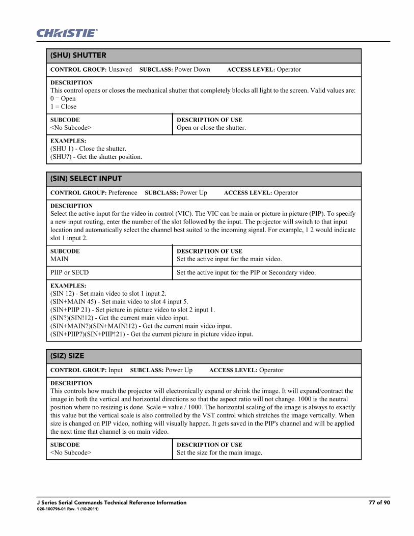
(SHU) SHUTTER
CONTROL GROUP: Unsaved SUBCLASS: Power Down ACCESS LEVEL: Operator
DESCRIPTIONThis control opens or closes the mechanical shutter that completely blocks all light to the screen. Valid values are: 0 = Open 1 = Close
SUBCODE<No Subcode>
DESCRIPTION OF USEOpen or close the shutter.
EXAMPLES:(SHU 1) - Close the shutter. (SHU?) - Get the shutter position.
(SIN) SELECT INPUT
CONTROL GROUP: Preference SUBCLASS: Power Up ACCESS LEVEL: Operator
DESCRIPTIONSelect the active input for the video in control (VIC). The VIC can be main or picture in picture (PIP). To specify a new input routing, enter the number of the slot followed by the input. The projector will switch to that input location and automatically select the channel best suited to the incoming signal. For example, 1 2 would indicate slot 1 input 2.
SUBCODEMAIN
DESCRIPTION OF USESet the active input for the main video.
PIIP or SECD Set the active input for the PIP or Secondary video.
EXAMPLES:(SIN 12) - Set main video to slot 1 input 2. (SIN+MAIN 45) - Set main video to slot 4 input 5. (SIN+PIIP 21) - Set picture in picture video to slot 2 input 1. (SIN?)(SIN!12) - Get the current main video input. (SIN+MAIN?)(SIN+MAIN!12) - Get the current main video input. (SIN+PIIP?)(SIN+PIIP!21) - Get the current picture in picture video input.
(SIZ) SIZE
CONTROL GROUP: Input SUBCLASS: Power Up ACCESS LEVEL: Operator
DESCRIPTIONThis controls how much the projector will electronically expand or shrink the image. It will expand/contract the image in both the vertical and horizontal directions so that the aspect ratio will not change. 1000 is the neutral position where no resizing is done. Scale = value / 1000. The horizontal scaling of the image is always to exactly this value but the vertical scale is also controlled by the VST control which stretches the image vertically. When size is changed on PIP video, nothing will visually happen. It gets saved in the PIP's channel and will be applied the next time that channel is on main video.
SUBCODE<No Subcode>
DESCRIPTION OF USESet the size for the main image.
J Series Serial Commands Technical Reference Information 77 of 90020-100796-01 Rev. 1 (10-2011)

(SIZ) Size con’t
EXAMPLES:(SIZ 500) - Set size to 500 on main video. (SIZ?) - Returns the size value on main video.
(SMP) SAMPLING MODE
CONTROL GROUP: Input SUBCLASS: Power Up ACCESS LEVEL: Operator
DESCRIPTIONThis control sets the color sampling mode for a digital signal to either YCbCr 4:4:4, RGB or YCbCr 4:2:2. Although the proper sampling mode is determined automatically by the projector, you can override the setting. Valid values are: 0 = YCbCr 4:4:4 (or RGB) 1 = YCbCr 4:2:2
SUBCODEINxy
DESCRIPTION OF USESet the sampling mode on slot x, input y.
MAIN Set the sampling mode on main video.
PIIP or SECD Set the sampling mode on PIP or Secondary video.
EXAMPLES:(SMP 1) - Set sampling mode to YCbCr422 on main video. (SMP+MAIN 0) - Set sampling mode to YCbCr444 on main video. (SMP+PIIP 1) - Set sampling mode to YCbCr422 on PIP video. (SMP+IN32 1) - Set sampling mode to YCbCr422 on slot 3 input 2. (SMP?) - Returns the current sampling mode value on main video. (SMP+PIIP?) - Returns the current sampling mode value on PIP video. (SMP+IN12?) - Returns the current sampling mode value on slot 1 input 2.
(SOR) SCREEN ORIENTATION
CONTROL GROUP: Preference SUBCLASS: Power Up ACCESS LEVEL: Operator
DESCRIPTIONSelects the orientation of the displayed image. It can be displayed normally, inverted horizontally, inverted verti-cally, or inverted in both directions, as required by the projector installation. Valid values are: 0 = Front Projection 1 = Rear Projection 2 = Front Projection Inverted 3 = Rear Projection Inverted
SUBCODE<No Subcode>
DESCRIPTION OF USESelect screen orientation.
EXAMPLE:(SOR 0) - Set image orientation to Front projection.
78 of 90 J Series Serial Commands Technical Reference Information020-100796-01 Rev. 1 (10-2011)

(SPS) SPLASH SCREEN
CONTROL GROUP: Preference SUBCLASS: Power Up ACCESS LEVEL: Operator
DESCRIPTIONUpload a User Splash Screen (logo) bitmap and configure splash screen display options.
SUBCODE<No Subcode>
DESCRIPTION OF USEView/Set option indicating when a logo is displayed. Valid values are: 0 = Always off 1 = Display on Startup only 2 = Display on Startup and when there is no Signal
BACK View/Set logo background color.
DLET Delete user logo from storage flash.
SLCT View/Set which logo to display. Valid values are: 0 = Default Splash Screen 1 = User Splash Screen
XPOS View/Set logo horizontal position.
YPOS View/Set logo vertical position.
EXAMPLES:(SPS ?) - Get the display option. If 0, logo is always off. 1, logo is displayed at start up, etc. (SPS 2) - Set the display option. Logo will be displayed when there is no signal. (SPS+SLCT 0) - Use Christie logo. (SPS+BACK 225) - Set background color of user logo screen to Blue. Value format: 0xRRGGBB (must be con-verted to decimal).(SPS+DLET 1) - Delete user logo from flash.(SPS+SIMG 1) - Set option to show logo image on user logo screen.(SPS+SIMG 0) - Set option to hide logo image and only display background color on user logo screen.(SPS+XPOS 50) Move the logo image on user logo screen to 50th pixel from left screen edge.(SPS+YPOS 50) - Move the logo image on user logo screen to 50th pixel from top screen edge.
(SPT) SPLIT SCREEN
CONTROL GROUP: Unsaved SUBCLASS: Power Up ACCESS LEVEL: Operator
DESCRIPTIONSplit screen enable control. Allows a snap shot of the main image to be presented on the right side of the screen to allow evaluation of advanced image processing features. All resizing controls are honoured on both images. How-ever, image processing controls only happen on the left side image. Changing inputs, channels or test patterns will disable this control. PIP operation must be disabled prior to enabling this control. Valid options are: 0 = Off 1 = Side 2 = Top
SUBCODE<No Subcode>
DESCRIPTION OF USESelect split screen method.
J Series Serial Commands Technical Reference Information 79 of 90020-100796-01 Rev. 1 (10-2011)

(SPT) Split Screen con’t
EXAMPLES:(SPT 1) - Turn on split screen to the side. (SPT 0) - Turn off split screen.
(SST) SYSTEM STATUS
CONTROL GROUP: Preference SUBCLASS: Power Down ACCESS LEVEL: Status
DESCRIPTIONRetrieve the various system status groups.
SUBCODE<No Subcode>
DESCRIPTION OF USEReturns information on all status groups, with one message per item.
ALRM Returns a summary of any active alarms.
CONF Returns configuration data - model, serial number, build date, etc.
COOL Returns cooling data - cooling fans, air flow, etc.
HLTH Returns system health.
LAMP Returns LAMP operational data.
SIGN Returns signal data - frequency, etc.
SYST Returns system data - power, hours of use, shutter open, etc.
TEMP Returns temperature data.
VERS Returns version numbers.
EXAMPLES:(SST+ALRM?) returns (SST+ALRM!000 002 "101" "Prism temperature") where parameters are P1=index number, P2=error level, P3=value, P4=description. Error level is 0=no errors or warnings, 1=warning, 2=error, 3=error and warning.
80 of 90 J Series Serial Commands Technical Reference Information020-100796-01 Rev. 1 (10-2011)

(STD) VIDEO STANDARD
CONTROL GROUP: Input SUBCLASS: Power Up ACCESS LEVEL: Operator
DESCRIPTION
This control displays or sets the current video standard that is decoding the input signal. You can allow the projector to automatically determine the standard or you can specify a specific standard from the selection list.
0 = Auto. Automatically determined by decoder. 1 = PAL is a commonly used format in much of Europe, China, Australia and some South American and African countries. 2 = NTSC is a commonly used format in North America and Japan. 3 = SECAM is a format found primarily in France, Eastern Europe and much of Africa. 4 = NTSC44 is a tape-only standard and is usually used with hybrid signals used to provide compatibility with video material of another TV format without a complete translation. 5 = PAL-M is a format found primarily in Brazil. 6 = PAL-NC is a format found primarily in Argentina and Chile and some other Latin American countries. 7 = PAL-60 Only those standards that have similar horizontal and vertical frequencies to the current input source are enabled.
SUBCODEINxy
DESCRIPTION OF USESet the video standard on slot input y to the specified value in the range of known video standards.
MAIN Set the video standard on the main video to the specified value in the range of known video standards.
PIIP or SECD Set the video standard on the PIP or Secondary video to the speci-fied value in the range of known video standards.
EXAMPLES:(STD 0) - Set video standard to 0 (PAL) on main video. (STD+MAIN 1) - Set video standard to 1(NTSC_M) on main video. (STD+PIIP 0) - Set video standard to 0(PAL) on PIP video. (STD+IN32 3) - Set video standard to 3(NTSC_4_43) on slot 3 input 2. (STD ?) - Returns the current video standard on main video. (STD+PIIP ?) - Returns the current video standard value on PIP video. (STD+IN12 ?) - Returns the current video standard value on slot 1 input 2.
(SZP) SIZE PRESETS
CONTROL GROUP: Unsaved SUBCLASS: Power Up ACCESS LEVEL: Operator
DESCRIPTIONSets the image to one of several preset size/position presets. 0 = Default 1 = None 2 = Full Screen 3 = Full Width 4 = Full Height 5 = Anamorphic 6 = Custom
J Series Serial Commands Technical Reference Information 81 of 90020-100796-01 Rev. 1 (10-2011)

(SZP) Size Presets con’t
SUBCODE<No Subcode>
DESCRIPTION OF USESet preset size type.
EXAMPLE:(SZP 1) - Set the size preset to no resizing.
(TBL) TOP BLANKING
CONTROL GROUP: Input SUBCLASS: Power Up ACCESS LEVEL: Operator
DESCRIPTIONSet the number of lines to blank (turn to black) at the top of the image. This can be used to blank out any unwanted data near the top edge of the image. A positive amount of blanking makes the image smaller. A negative amount of blanking makes the image larger. Negative blanking is only applicable to analog signals, when the autosetup has not been able to set the image size correctly. It is preferable not to use negative blanking, but to run autosetup again, ensuring that the content has active pixels on each edge of the image. The maximum amount of top blanking allowed is half the image height minus 10. For negative blanking, the image size can only be increased to the limit of the sync.
SUBCODENix
DESCRIPTION OF USESet the top blanking for slot x, input y.
MAIN Set the top blanking for the main image.
PIIP or SECD Set the top blanking for the PIP or Secondary image.
EXAMPLES:(TBL 40) - Set top blanking to 40 on main video. (TBL+MAIN 40) - Set top blanking to 40 on main video. (TBL+PIIP 40) - Set top blanking to 40 on PIP video. (TBL+IN32 40) - Set top blanking to 40 on slot 3 input 2. (TBL?) - Returns the top blanking value on main video. (TBL+PIIP?) - Returns the top blanking value on PIP video. (TBL+IN12?) - Returns the top blanking value on slot 1 input 2.
(TDD) 3D EMITTER DELAY
CONTROL GROUP: Input SUBCLASS: Power Up ACCESS LEVEL: Operator
DESCRIPTIONAdjust the output 3D emitter delay to match the active glasses to the L/R frames of the projector. Proper adjust-ment of this delay will eliminate cross talk and odd colors caused by timing differences between the glasses and the projected image. The user specified delay is added after sync locking.
SUBCODEMAIN
DESCRIPTION OF USESet the 3D Emitter Delay for the main image.
INxy Set the 3D Emitter Delay for slot x, input y.
82 of 90 J Series Serial Commands Technical Reference Information020-100796-01 Rev. 1 (10-2011)

(TDD) 3D Emitter Delay con’t
EXAMPLES:(TDD 2000) - Set 3D Emitter Delay to 20.00 milliseconds on main video. (TDD+MAIN 1000) - Set 3D Emitter Delay to 10.00 milliseconds on main. (TDD+IN12 2500) - set 3D Emitter Delay to 25.00 milliseconds on slot 1 input 2. (TDD?) - Returns the 3D Emitter Delay value on main video. (TDD+IN12?) - Returns the 3D Emitter Delay value on slot 1 input 2.
(TDI) 3D SYNC INPUT
CONTROL GROUP: Input SUBCLASS: Power Up ACCESS LEVEL: Operator
DESCRIPTIONThe 3D sync signal is generated by the 3D source to ensure left/right eye content is synchronized to the projector and to the user. The 3D Stereo cable has 2 inputs for right eye - left eye signals. This control specifies which of the 2 right-left eye input signals on the cable is active. It is important to ensure that the correct 3D sync input is selected (either Input A or Input B) with each 3D signal source. If there is no external sync, then choose None and the sync will be generated internally. This allows the content to be displayed, however, there is a 50% chance that the content will be displayed with the left/right eyes swapped or inverted. This function is not used in Interleaved 3D mode as each eye gets a dedicated input and no 3D sync input is required.
SUBCODEMAIN
DESCRIPTION OF USESet the 3D Sync Input for the main image.
INxy Set the 3D Sync Input for slot x, input y.
EXAMPLES:(TDI 0) - Set 3D Sync Input to 'A' on main video (TDI+MAIN 1) - Set 3D Sync Input to 'B' on main (TDI+IN12 2) - Set 3D Sync Input to 'Internal' on slot 1 input 2 (TDI?) - Returns the 3D Sync Input value on main video (TDI+IN12?) - Returns the 3D Sync Input value on slot 1 input 2
J Series Serial Commands Technical Reference Information 83 of 90020-100796-01 Rev. 1 (10-2011)

(TDM) 3D MODE
CONTROL GROUP: Input SUBCLASS: Power Up ACCESS LEVEL: Operator
DESCRIPTIONSelect the 3D mode:Off: 3D operation is disabled.Auto 3D: Attempts to automatically determine which 3D mode to use.Native 3D: All content is shown at native frame rate from 96-120Hz input and output.Frame Doubled 3D: 3D Content from a single 48-60Hz signal (24/30Hz per eye) are displayed twice to provide a 3D content to be viewed at 96-120Hz to the user.Dual Input 3D: Content from two independent 48-60Hz “passive” frame locked sources are interleaved into a native 96-120Hz native frame rate. This requires an optional input module and both signals must be from the same signal type. Side-by-Side 3D: Content is transmitted with each eye above one another in a single frame at half resolution, and is extracted and scaled to show in an alternate-frame sequence.Top/Bottom 3D: Content is transmitted with each eye above one another in a single frame at half resolution, and is extracted and scaled to show in an alternate-frame sequence.Frame Packed 3D: Content is transmitted with each eye at full resolution in a double-sized frame, and extracted to show in an alternate-frame sequence. This mode is typically used for BlueRay-3D movies and 3D video gaming.
SUBCODEMAIN
DESCRIPTION OF USESet the 3D Mode for the main image.
INxy Set the 3D Mode for slot x, input y.
EXAMPLES:(TDM 0) - Set 3D Mode to 'Off' on main video. (TDM+MAIN 1) - Set 3D Mode to "Native 3D" on main. (TDM+IN12 2) -Set 3D Mode to "Frame Doubled" on slot 1 input 2. (TDM?) - Returns the 3D Mode value on main video. (TDM+IN12?) - Returns the 3D Mode value on slot 1 input 2.
(TDN) INVERT 3D INPUT
CONTROL GROUP: Input SUBCLASS: Power Up ACCESS LEVEL: Operator
DESCRIPTIONAdjust the output 3D emitter delay to match the active glasses to the L/R frames of the projector. Proper adjust-ment of this delay will eliminate cross talk and odd colors caused by timing differences between the glasses and the projected image. The user specified delay is added after sync locking.
SUBCODEMAIN
DESCRIPTION OF USESet the 3D input inversion for the main image.
INxy Set the 3D input inversion for slot x, input y.
EXAMPLES:(TDN 1) - Set 3Dinput inversion to 'inverted' on main video. (TDN+MAIN 0) - Set 3D input inversion to 'not inverted' on main. (TDN+IN12 0) - Set 3D input inversion to 'not inverted' on slot 1 input 2. (TDN?) - Returns the 3D input inversion value on main video. (TDN+IN12?) - Returns the 3D input inversion value on slot 1 input 2.
84 of 90 J Series Serial Commands Technical Reference Information020-100796-01 Rev. 1 (10-2011)

(TDO) 3D SYNC OUT
CONTROL GROUP: Input SUBCLASS: Power Up ACCESS LEVEL: Operator
DESCRIPTIONThis defines if the 3D Sync is output and controls how it is processed. It is only valid when a cable is used to con-nect stereo 3D signals to the projector via the GPIO port. When there is no 3D signal, Sync Output should be 'Off'. Typically only the last projector in the 3D Stereo cable chain is connected to the emitter and should specify 'To Emitter'. All other projectors should select 'To Next Input' if other projectors are used in the chain. When power is off, the output becomes locked to the input - when power is restored, the user specified state is restored.
SUBCODEMAIN
DESCRIPTION OF USESet the 3D Sync Out for the main image.
INxy Set the 3D Sync Out for slot x, input y.
EXAMPLES:(TDO 0) - Set 3D Sync Out to 'off' on main video (TDO+MAIN 1) - Set 3D Sync Out to 'To Emitter' on main (TDO+IN12 2) - Set 3D Sync Out to 'To Next' on slot 1 input 2 (TDO?) - Returns the 3D Sync Out value on main video (TDO+IN12?) - Returns the 3D Sync Out value on slot 1 input 2
(TDT) 3D TEST PATTERN
CONTROL GROUP: Unsaved SUBCLASS: Power Up ACCESS LEVEL: Operator
DESCRIPTIONEnables a 3D test pattern for diagnostics. The scrolling diagonal lines indicate how well left and right are syn-chronized. If ghosting is occurring, the input may have to be switched or inverted. Adjustments to the emitter delay can also help correct the synchronization.
SUBCODE<No Subcode>
DESCRIPTION OF USEEnable or disable 3D test pattern.
EXAMPLES:(TDT 1) - Enable 3D test pattern (TDT 0) - Disable 3D test pattern
(TED) TWIN HDMI EDID TYPE SELECTION
CONTROL GROUP: Option SUBCLASS: Power Up ACCESS LEVEL: Operator
DESCRIPTIONSet the preferred EDID Timings on the Twin HDMI input card. Available Models are:0 = Default1 = 3D2 = Custom
SUBCODESLxy
DESCRIPTION OF USESet the EDID timings on slot x to the specified type.
J Series Serial Commands Technical Reference Information 85 of 90020-100796-01 Rev. 1 (10-2011)

(TED) Twin HDMI EDID Type Selection con’t
EXAMPLES:(TED+SL31 1) - Set EDID type to 1 (3D) on slot 3 input 1.(TED+SL12?) - Returns the current EDID type on slot 1 input 2.
(TIL) TILING CONTROL
CONTROL GROUP: Preference SUBCLASS: Power Up ACCESS LEVEL: Operator
DESCRIPTIONSet the projector as part of a tiled array.
SUBCODESLCT
DESCRIPTION OF USEEnable or disable tiling.
RTOT Set the total number of rows in the projector array.
CTOT Set the total number of columns in the projector array.
RVAL Set the row number of this projector.
CVAL Set the column number of this projector.
EXAMPLES:(TIL+SLCT 1) - Enable tiling. (TIL+RTOT 2) - Set the total number of rows of projectors to 2. (TIL+CTOT 2) - Set the total number of columns of projectors to 2. (TIL+RVAL 2) - Set the projector to be in the 2nd row.(TIL+CVAL 1) - Set the projector to be in the 1st column.
(TMD) TIME/DATE
CONTROL GROUP: Preference SUBCLASS: Power Down ACCESS LEVEL: Admin
DESCRIPTIONSet the date, time or time zone.
SUBCODEDATE
DESCRIPTION OF USESet the date in the form yyyy/mm/dd.
TIME Set the local time in the form hh:mm:ss Note: Currently, time must be set using 24hr clock (regardless of LOC+TIME setting).
EXAMPLES: (TMD+TIME "17:50:45") - Set new local time. (TMD+DATE "2007/02/30") - Set the local date. (TMD+TIME?) - Get local time (TMD+TIME! 17:50:45).
86 of 90 J Series Serial Commands Technical Reference Information020-100796-01 Rev. 1 (10-2011)

(TNT) TINT
CONTROL GROUP: Input SUBCLASS: Power Up ACCESS LEVEL: Operator
DESCRIPTIONTint adjusts the balance of red-to-green in your image. It is useful only for video images processed by decoder cards.
SUBCODEINxy
DESCRIPTION OF USESet the tint level on slot x, input y to the specified value in the range of -45 deg to 45 deg.
MAIN Set the tint level on the main video to the specified value in the range -45 deg to 45 deg.
PIIP or SECD Set the tint level on the PIP or Secondary video to the specified value in the range of -45 deg to 45 deg.
EXAMPLES:(TNT 40) - Set tint level to 40 on main video. (TNT MAIN 40) - Set tint level to 40 on main video. (TNT PIP 20) - Set tint level to 20 on PIP video. (TNT IN32 40) - Set tint level to 40 on slot 3 input 2. (TNT ?) - Returns the current tint level on main video. (TNT PIP ?) - Returns the current tint level on PIP video. (TNT IN12 ?) - Returns the current tint level on slot 1 input 2.
(TTM) THIC TRANSMITTER MODE CONFIGURATION
CONTROL GROUP: Option SUBCLASS: Power Down ACCESS LEVEL: Operator
DESCRIPTIONSelect a working mode for one of the transmitters on the THIC card.0 = 'Default' to select 12-bit per channel HDMI output1 = 'Compatible' to select 8-bit per channel HDMI output2 = 'DVI only' to select 8-bit per channel DVI output
SUBCODESLxy
DESCRIPTION OF USESet transmitter working mode for THIC card.
EXAMPLES:(TTM+SL11 0) - Use 12 bit HDMI output for THIC on slot1 input 1. (TTM+SL42 1) - Use 8 bit HDMI output for THIC on slot4 input 2. (TTM+SL11 2) - Use 8 bit DVI output for THIC on slot1 input 1. (TTM+SL12 ?) - Get the transmitter working mode for THIC on slot1 input 2.
J Series Serial Commands Technical Reference Information 87 of 90020-100796-01 Rev. 1 (10-2011)

(TXE) TEXTURE ENHANCEMENT
CONTROL GROUP: Input SUBCLASS: Power Up ACCESS LEVEL: Operator
DESCRIPTIONApplies texture detail enhancement based on adaptive horizontal, vertical and diagonal large edge and small edge enhancement processes.
SUBCODEINxy
DESCRIPTION OF USESet the texture enhancement for slot x, input y.
MAIN Set the texture enhancement for main video.
PIIP or SECD Set the texture enhancement for PIP or Secondary video.
EXAMPLE:(TXE 50) - Set the texture enhancement to 50% for main video.
(UID) USER ID
CONTROL GROUP: Unsaved SUBCLASS: Power Down ACCESS LEVEL: None
DESCRIPTIONAllows users to login to the serial interface.
SUBCODE<No Subcode>
DESCRIPTION OF USEEnter user ID and password.
EXAMPLES:(UID "username" "password") - Login a user. (UID) - Logout the current user, also happens automatically when a new user logs in. (UID?)(UID!"username" 01) - Display the current logged in user and their access level.
(VBL) VIDEO BLACK INPUT
CONTROL GROUP: Input SUBCLASS: Power Up ACCESS LEVEL: Operator
DESCRIPTIONThis control affects the black level for video signals. Most NTSC video standards include an offset to black which is useful for setting up CRT projectors. Set this control to 7.5 IRE if the video black level seems excessively ele-vated. Set to 0 IRE if video black levels are crushed. This control applies to analog cards with YUV color space only. Valid values are: 0 = 0 IRE 1 = 7.5 IRE
SUBCODEINxy
DESCRIPTION OF USEGet the video black level for slot x, input y.
MAIN Set the video black level for main video.
PIIP or SECD Set the video black level for PIP or Secondary video.
EXAMPLES:(VBL 1) - Set the video black level for main video to 7.5IRE. (VBL+MAIN 1) - Set the video black level for main video to 7.5IRE. (VBL+IN32 0) - Set the video black level for PIP video to 0IRE. (VBL?) - Returns the video black level on main video.
88 of 90 J Series Serial Commands Technical Reference Information020-100796-01 Rev. 1 (10-2011)
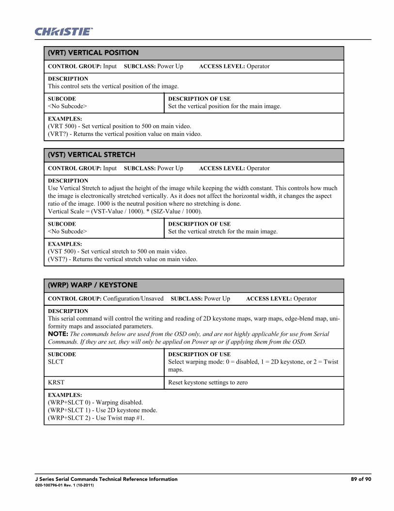
(VRT) VERTICAL POSITION
CONTROL GROUP: Input SUBCLASS: Power Up ACCESS LEVEL: Operator
DESCRIPTIONThis control sets the vertical position of the image.
SUBCODE<No Subcode>
DESCRIPTION OF USESet the vertical position for the main image.
EXAMPLES:(VRT 500) - Set vertical position to 500 on main video. (VRT?) - Returns the vertical position value on main video.
(VST) VERTICAL STRETCH
CONTROL GROUP: Input SUBCLASS: Power Up ACCESS LEVEL: Operator
DESCRIPTIONUse Vertical Stretch to adjust the height of the image while keeping the width constant. This controls how much the image is electronically stretched vertically. As it does not affect the horizontal width, it changes the aspect ratio of the image. 1000 is the neutral position where no stretching is done. Vertical Scale = (VST-Value / 1000). * (SIZ-Value / 1000).
SUBCODE<No Subcode>
DESCRIPTION OF USESet the vertical stretch for the main image.
EXAMPLES:(VST 500) - Set vertical stretch to 500 on main video. (VST?) - Returns the vertical stretch value on main video.
(WRP) WARP / KEYSTONE
CONTROL GROUP: Configuration/Unsaved SUBCLASS: Power Up ACCESS LEVEL: Operator
DESCRIPTIONThis serial command will control the writing and reading of 2D keystone maps, warp maps, edge-blend map, uni-formity maps and associated parameters. NOTE: The commands below are used from the OSD only, and are not highly applicable for use from Serial Commands. If they are set, they will only be applied on Power up or if applying them from the OSD.
SUBCODESLCT
DESCRIPTION OF USESelect warping mode: 0 = disabled, 1 = 2D keystone, or 2 = Twist maps.
KRST Reset keystone settings to zero
EXAMPLES:(WRP+SLCT 0) - Warping disabled. (WRP+SLCT 1) - Use 2D keystone mode.(WRP+SLCT 2) - Use Twist map #1.
J Series Serial Commands Technical Reference Information 89 of 90020-100796-01 Rev. 1 (10-2011)

(ZOM) LENS ZOOM POSITION ADJUSTMENT
CONTROL GROUP: Configuration SUBCLASS: Power Up ACCESS LEVEL: Operator
DESCRIPTIONAdjust the lens zoom to a specific position.
SUBCODE<No Subcode>
DESCRIPTION OF USEMove the zoom motor to a specified position. The default data range is -1200 to 1200. The range may change after running the Lens Calibration function, which determines the full range allowed by the hardware.
EXAMPLE:(ZOM 500) - Move lens zoom to position 500.
90 of 90 J Series Serial Commands Technical Reference Information020-100796-01 Rev. 1 (10-2011)