J. Micromech. Microeng. 21 (2011) 054013 (9pp) Thermal ... · existence of surface cracks in PDMS...
9
IOP PUBLISHING JOURNAL OF MICROMECHANICS AND MICROENGINEERING J. Micromech. Microeng. 21 (2011) 054013 (9pp) doi:10.1088/0960-1317/21/5/054013 Thermal fracture of oxidized polydimethylsiloxane during soft lithography of nanopost arrays Wes W Tooley, Shirin Feghhi, Sangyoon J Han, Junlan Wang and Nathan J Sniadecki 1 Department of Mechanical Engineering, Universityof Washington, Seattle, WA 98195-2600, USA E-mail: [email protected] Received 31 October 2010, in final form 29 January 2011 Published 28 April 2011 Online at stacks.iop.org/JMM/21/054013 Abstract During the fabrication of nanopost arrays for measuring cellular forces, we have observed surface cracks in the negative molds used to replicate the arrays from a silicon master. These cracks become more numerous and severe with each replication such that repeated castings lead to arrays with missing or broken posts. This loss in pattern fidelity from the silicon master undermines the spatial resolution of the nanopost arrays in measuring cellular forces. We hypothesized that these cracks are formed because of a mismatch in the coefficient of thermal expansion (CTE) of polydimethylsiloxane (PDMS) and its oxidized surface layer. To study the fracture of PDMS due to thermal effects, we treated circular test samples of PDMS with oxidizing plasma and then heated them to cause surface cracks. These cracks were found to be more abundant at 180 ◦ C than at lower temperatures. Finite element analysis of a bilayer material with a CTE mismatch was used to validate that thermal stresses are sufficient to overcome the fracture toughness of oxidized PDMS. As a consequence, we have ascertained that elevated temperatures are a significant detriment to the reproducibility of nanoscale features in PDMS during replica molding. S Online supplementary data available from stacks.iop.org/JMM/21/054013/mmedia (Some figures in this article are in colour only in the electronic version) Introduction Soft lithography is a set of manufacturing techniques for the fabrication of micro- and nanoscale structures [1]. It complements silicon-based fabrication techniques because it uses an elastic material, polydimethylsiloxane (PDMS), to replicate intricate features made in silicon or photoresist in a rapid and inexpensive manner [2]. Soft lithography is quite versatile in biological applications for it can be used to form fluid channels for biosensor platforms [3–5], flexible stamps for patterning biomolecules and cells [6], and topological surfaces for mimicking the native cellular environment [7]. PDMS is biocompatible and its surface can be functionalized with extracellular matrix proteins that facilitate the adhesion 1 Author to whom any correspondence should be addressed. of cells and allow for their long-term culture on PDMS devices [8, 9]. Since PDMS is also mechanically flexible, it can be used to replicate arrays of posts for measuring cellular forces [10–13]. Recently, nanopost arrays have been produced, which provide better spatial resolution of cellular forces than micropost arrays due to the higher density of flexible PDMS post sensors underneath a cell (figure 1)[12]. PDMS is an organosilicon polymer that is synthesized from dimethylsiloxane oligomers with vinyl-terminated end groups, dimethylvinylated and trimethylated silica filler, a platinum catalyst, a cross-linking agent, dimethylmethylhydrogen siloxane, and an inhibitor, tetramethyltetravinyl cyclotetrasiloxane [8]. This mixture undergoes a hydrosilylation reaction which results in silicon- carbon bonding between the siloxane oligomers and silica filler to create a solid, elastic material. Heat is typically added 0960-1317/11/054013+09$33.00 1 © 2011 IOP Publishing Ltd Printed in the UK & the USA
Transcript of J. Micromech. Microeng. 21 (2011) 054013 (9pp) Thermal ... · existence of surface cracks in PDMS...
IOP PUBLISHING JOURNAL OF MICROMECHANICS AND MICROENGINEERING
J. Micromech. Microeng. 21 (2011) 054013 (9pp) doi:10.1088/0960-1317/21/5/054013
Thermal fracture of oxidizedpolydimethylsiloxane during softlithography of nanopost arraysWes W Tooley, Shirin Feghhi, Sangyoon J Han, Junlan Wang andNathan J Sniadecki1
Department of Mechanical Engineering, University of Washington, Seattle, WA 98195-2600, USA
E-mail: [email protected]
Received 31 October 2010, in final form 29 January 2011Published 28 April 2011Online at stacks.iop.org/JMM/21/054013
AbstractDuring the fabrication of nanopost arrays for measuring cellular forces, we have observedsurface cracks in the negative molds used to replicate the arrays from a silicon master. Thesecracks become more numerous and severe with each replication such that repeated castingslead to arrays with missing or broken posts. This loss in pattern fidelity from the silicon masterundermines the spatial resolution of the nanopost arrays in measuring cellular forces. Wehypothesized that these cracks are formed because of a mismatch in the coefficient of thermalexpansion (CTE) of polydimethylsiloxane (PDMS) and its oxidized surface layer. To study thefracture of PDMS due to thermal effects, we treated circular test samples of PDMS withoxidizing plasma and then heated them to cause surface cracks. These cracks were found to bemore abundant at 180 ◦C than at lower temperatures. Finite element analysis of a bilayermaterial with a CTE mismatch was used to validate that thermal stresses are sufficient toovercome the fracture toughness of oxidized PDMS. As a consequence, we have ascertainedthat elevated temperatures are a significant detriment to the reproducibility of nanoscalefeatures in PDMS during replica molding.
S Online supplementary data available from stacks.iop.org/JMM/21/054013/mmedia
(Some figures in this article are in colour only in the electronic version)
Introduction
Soft lithography is a set of manufacturing techniques forthe fabrication of micro- and nanoscale structures [1]. Itcomplements silicon-based fabrication techniques because ituses an elastic material, polydimethylsiloxane (PDMS), toreplicate intricate features made in silicon or photoresist ina rapid and inexpensive manner [2]. Soft lithography is quiteversatile in biological applications for it can be used to formfluid channels for biosensor platforms [3–5], flexible stampsfor patterning biomolecules and cells [6], and topologicalsurfaces for mimicking the native cellular environment [7].PDMS is biocompatible and its surface can be functionalizedwith extracellular matrix proteins that facilitate the adhesion
1 Author to whom any correspondence should be addressed.
of cells and allow for their long-term culture on PDMS devices[8, 9]. Since PDMS is also mechanically flexible, it can beused to replicate arrays of posts for measuring cellular forces[10–13]. Recently, nanopost arrays have been produced,which provide better spatial resolution of cellular forces thanmicropost arrays due to the higher density of flexible PDMSpost sensors underneath a cell (figure 1) [12].
PDMS is an organosilicon polymer that issynthesized from dimethylsiloxane oligomers withvinyl-terminated end groups, dimethylvinylated andtrimethylated silica filler, a platinum catalyst, a cross-linkingagent, dimethylmethylhydrogen siloxane, and an inhibitor,tetramethyltetravinyl cyclotetrasiloxane [8]. This mixtureundergoes a hydrosilylation reaction which results in silicon-carbon bonding between the siloxane oligomers and silicafiller to create a solid, elastic material. Heat is typically added
0960-1317/11/054013+09$33.00 1 © 2011 IOP Publishing Ltd Printed in the UK & the USA

J. Micromech. Microeng. 21 (2011) 054013 W W Tooley et al
(a)
(b)
(c)
Figure 1. (a) SEM image of the PDMS nanopost array made bydouble-casting from a silicon master. (b) Immunofluorescenceimage of 3T3 fibroblast on the nanopost array (blue: DAPI; green:phalloidin; red: posts). (c) Traction force vectors were measured byanalyzing the deflection of the nanoposts. This relationship is givenby F = ( 3
4 πEr4/h3) d, where F is the cell’s traction force, E is theYoung modulus, d is the deflection, r is the radius, and h is theheight of the post.
during the organometallic cross-linking reaction to speed upthe curing process. Once cured, the polymer has a coefficientof thermal expansion (CTE) of 3.1 × 10⁻⁴ K−1 [14–16].The Young modulus of PDMS can range between 0.7 and3.5 MPa, depending on the mixing ratio, curing temperature,and baking time [17–20]. The Young modulus of PDMS islower than silicon-based or metallic materials and allows forit to undergo large elastic deformations during its removalfrom a master template with micro- or nanoscale features.
For the nanopost arrays, a double-casting process is usedto replicate the arrays in PDMS from a single silicon master
Figure 2. Schematic of the double-casting process to form nanopostarrays made from PDMS.
(figure 2). Several identical copies of the arrays are neededfor experiments on cellular traction forces, so a fast and cost-effective replication process is needed [21]. During double-casting, uncured PDMS is cast against a master template witharrays of posts to create a negative that contains arrays of holes.The negatives are subsequently treated with oxidizing plasmato create silanol groups on the surface of the PDMS [22–24],which are then reacted with a fluorinated alkyltrichlorosilaneto render a low surface energy coating on the negative [22,23, 25]. Next, uncured PDMS is poured into the negatives,thermally cured, and peeled to release the newly formed arraysof posts. Although the double-casting process as describedpertains specifically to arrays of posts, it has also been usedto create patterns for stamps used in microcontact printing[25] and nanostructured topographies used to increase cellularadhesion [26].
During the double-casting process, we have observedsurface cracks in the negative molds after casting(figure 3). These cracks are small and are generally considereda minor issue for soft lithography of microscale features.However, they raise a concern that soft lithography may havelimits in replicating features at the nanoscale (figure 4). Theexistence of surface cracks in PDMS is well known andhas been observed when PDMS is subjected to prolongedplasma treatments [27, 28], when stretched, plasma-treated,and released to cause the surface layer to buckle [29, 30], orvice versa when PDMS is plasma-treated and then stretchedin order to fracture the surface [31, 32]. Plasma treatmentof PDMS forms a brittle, superficial layer that is tens to
2

J. Micromech. Microeng. 21 (2011) 054013 W W Tooley et al
(a) (b)
(c) (d )
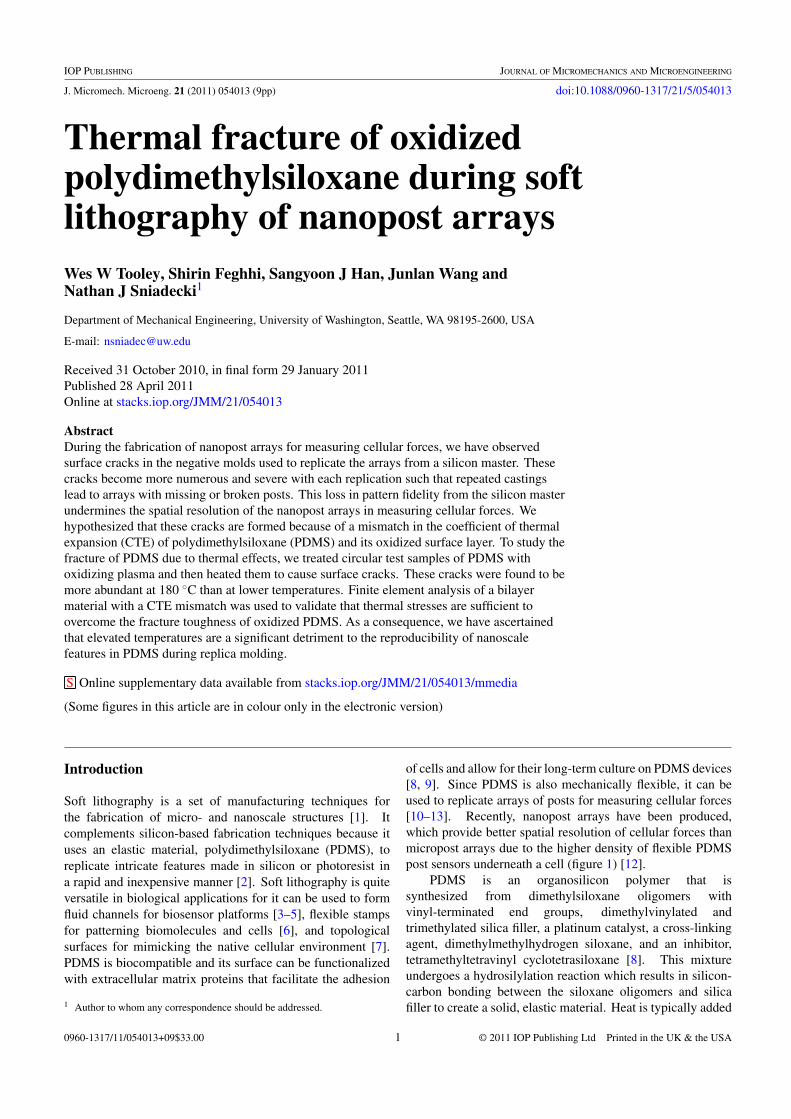
Figure 3. (a) Schematic diagram of the negative molds show thatthey contain arrays of holes that are surrounded by flat, rectangularregions with the same depth as the holes. (b) Phase contrast imageof a negative mold before casting the post arrays. The surface of thenegative has been plasma-treated and fluoro-silanized, but crackswere not observed on the surface. The same negative mold is shownafter (c) two and (d) four castings. The black arrows indicate thecracks present after the initial casting, the white arrowheads indicatebranching, secondary cracks, and the white arrows indicate de novocracks.
hundreds of nanometers in thickness and has a higher oxygenand lower carbon content than pure PDMS [28, 33, 34].It is often referred to as a ‘silica-like layer’ even thoughits density and structure are not the same as pure silica[34]. Mechanical stress can be used to fracture the silica-like layer, but it has also been suggested that the crackscan arise from thermal stresses induced by a CTE mismatchbetween the underlying bulk PDMS and the silica-likelayer [35].
In this study, we investigated the role of thermal effects insurface crack formation during the soft lithography replicationof nanopost arrays. Previous studies on the fracturing ofoxidized PDMS have focused on mechanically applied strainsas the mechanism for crack formation [28, 33], but therole of thermal expansion in initiating surface cracks hasnot been well addressed. In the double-casting process,we observed that surface cracks accumulate with repeateduse of the negative molds and tend to branch from pre-existing cracks. Subsequently, we adopted a testing methodwhere circular test samples of PDMS were plasma-treated andthen heated to induce thermal strains that initiated surfacefractures. We found that increasing the heating temperature ofthe test samples led to a significant increase in the densityof these cracks. To complement the experimental study,we performed a finite element analysis to approximate themaximum stress in the oxidized PDMS layer due to a CTEmismatch and confirmed that it was sufficient to inducefracture.
(a)
(b)
Figure 4. (a) SEM image of nanopost arrays cast from negativemolds that had surface cracks. (b) SEM image of nanoposts showthat surface cracks cause posts to be broken off and missing fromwithin the array.
Materials and methods
Fabrication of PDMS posts
Uncured PDMS was prepared by mixing PDMS (Sylgard 184,Dow Corning) at a 10:1 ratio of the base to the curing agentand degassing under vacuum until all of the air bubbles wereremoved. Negative molds were formed by pouring PDMS overa silicon master template consisting of arrays of nanoposts.The fabrication of the silicon master has been describedpreviously [12]. The negatives were cured for 10 min at110 ◦C, and then peeled from the master template (figure 2).The negatives were subjected to 90 s of air plasma (Plasma PrepII, SPI supplies) at a pressure of 0.3 mbar, current of 100 mA,and power of 100 W and then silanized with (tridecafluoro-1,1,2,2-tetrahydrooctyl)-1-trichlorosilane (T2492-KG, UnitedChemical Technologies) in a desiccator under vacuum for over14 h.
Once silanized, the negatives were used repeatedly tocast arrays of posts. The arrays were formed by pouringPDMS into the negatives and curing at 110 ◦C for 2 h. Aplasma-treated glass slide was placed on top of the liquidPDMS before curing to create a rigid backing to the PDMS inorder to aid in peeling. After each casting, the surface of thenegatives was imaged under phase contrast microscopy (NikonTiE) with a 10× objective and cooled CCD camera (Clara,Andor Technology) to identify cracks that arose during softlithography. The orientation of each crack within the phase
3

J. Micromech. Microeng. 21 (2011) 054013 W W Tooley et al
contrast images was measured using custom-written codethat used functions in MATLAB’s image processing toolbox(Mathworks). The cracks were also analyzed using a scanningelectron microscope (SEM) (FEI Sirion) that was operatedwith a working distance of 5 mm and a voltage of 5 kV. Afilm of gold-palladium was sputtered onto the negative moldsto a thickness of approximately 7 nm before high resolutionimaging.
To test whether the surface cracks affected the alignmentand regularity of the nanoposts, arrays were cast from negativemolds with no visible cracks and from negative molds thatwere severely cracked. The arrays were immunofluorescentlystained with 5 μg ml−1 of DiI solution and their deflectionswere analyzed as previously described [12, 13]. Briefly, theaverage displacement per post was measured for each arrayby comparing the top and bottom centroid position of thenanoposts. This analysis was used to determine whether thenanoposts were distorted as a result of surface cracks.
Circular PDMS test samples
Uncured PDMS was prepared as described before and cast for1 h at 110 ◦C between two fluoro-silanized glass plates.Spacers made from 1 mm thick glass slides were placedbetween the glass plates to maintain a consistent PDMS sheetthickness. An American standard paper hole puncher wasused to cut 8 mm diameter test samples from the PDMS sheet.The top surfaces of the test samples were cleaned with Scotch R©
adhesive tape to remove dust and debris. The test samples werethen placed onto a glass slide so that they could be transportedand inspected. Plasma treatment of the surface of the testsamples was performed as described previously. The sampleswere then heated in gravity convection ovens at 150 or 180 ◦Cfor 1 h and allowed to cool before imaging the induced surfacecracks with phase contrast microscopy.
To quantify the density of the cracks on the surface ofthe test samples, phase contrast images were taken at fourcardinal points along the perimeter of each of the samples:north, south, east, and west. Image analysis of the density ofthe surface cracks in the collected images was conducted usinga custom-written code in MATLAB. Specifically, each imagewas binarized by thresholding above 33.3% of the maximumpixel intensity for the samples heated to 150 ◦C and 16.9%for the samples heated to 180 ◦C. The two threshold valueswere found by trial-and-error in order to achieve a faithfulsegmentation that partitioned out the surface cracks from thevisible debris in the PDMS or optical obstructions in the lightpath from the microscopy objective to the camera. Oncebinarized, the crack density in each image was quantified bydividing the number of pixels for the cracks by the total numberof pixels in the image. The results of the image analysis werestatistically compared with Student’s t-test.
Finite element modeling
A two-dimensional finite element model of a bilayer materialconsisting of a thin silica-like top layer and a PDMS baselayer was constructed in ANSYS 11.0 (figure 10(a)). The
two-dimensional model was a simplification of the three-dimensional circular PDMS samples because a circular diskcan be described mathematically as a rectangular shape thatis revolved about a central axis. The top layer was modeledwith a thickness of 50 nm, which we based upon the depthof the cracks we measured using atomic force microscopy(dimension 3100 AFM). Simulations were run with a Young’smodulus value that was varied between 10 MPa and 70 GPa,which are within previous estimates for oxidized PDMS [20,29, 30, 33, 34, 36]. Additionally, Poisson’s ratio of 0.2and CTE of 0.55 × 10⁻⁶ K−1 were used for the silica-likelayer since they are typical values for silica glass materials[37]. The underlying PDMS layer was given a thickness of1 mm, Young’s modulus of 3 MPa, and Poisson’s ratio of0.499, since PDMS can be assumed to be an incompressiblematerial. The CTE value used for PDMS was 3.1 × 10⁻⁴
K−1, which we verified by measuring the change in lengthof PDMS samples in an oven at elevated temperatures. Theboundary condition at the top surface was modeled as a freesurface that could expand under thermal effects, while thebottom surface was modeled with a fixed boundary conditiondue to adhesion and friction with the underlying glass slide.One end of the bilayer material was assigned a free surfaceboundary condition, while the other end was given a symmetricboundary condition since it was coincident with the centralaxis of revolution. A finite element mesh using quadratic,solid, eight-node elements (PLANE183) was constructed. Atemperature rise of 90 or 160 K was imposed on the model toinduce thermal expansion. The stress in the radial directionin the silica-like layer was reported since it causes mode Ifracture. Convergence in the result of each simulation wasconfirmed using multiple meshing densities.
Results and discussion
Surface cracks increase with repeated castings
Arrays of nanoposts were cast repeatedly from the samenegative mold to create identical PDMS replicas of a siliconmaster. Four flat, rectangular regions surround each array ofnanoposts and acted as stiff, support structures to prevent theposts from buckling during microcontact printing (figure 3(a))[10, 12, 21]. Phase contrast images of the negatives beforecasting the post arrays, but after plasma treatment and fluoro-silanizing, showed that there were no visible cracks on thesurface of the negatives (figure 3(b)). After casting, however,cracks were seen to span the surface of the negatives andgrew worse with additional replications (figures 3(c) and (d)).The black arrows indicate the initial cracks that formed onthe negative which remained present throughout the mold’slifetime of usage. Under phase contrast, these cracks appearto be darker and more pronounced with additional replications.
Once a crack had formed, it could act as an initiation pointfor new cracks. The white arrow heads indicate secondarycracks which arise after the initial cracks and intersect withthem. It is likely that the initial cracks provide pre-crackdefects or act as stress risers for the secondary cracks. The
4

J. Micromech. Microeng. 21 (2011) 054013 W W Tooley et al
(a)
(b)
Figure 5. (a) SEM images show that cracks form after the firstcasting with the negative mold. The cracks were present near theholes in the negative mold but were not seen on the walls of theholes. (b) SEM image of a wide surface crack with smallerbranching cracks.
formation of cracks within the array of post holes was muchless common than in the surrounding regions. They tendedto arise after several replications and were seen to formde novo and end abruptly (white arrows). Additionally,cracks that started in the surrounding regions were seen topropagate across the array of holes. These cracks appearedjagged and were seldom seen to generate branching, secondarycracks. The presence of cracks within the array of holes is amajor concern as they can cause posts to break off at theirbases, which undermines the spatial resolution of the arrays(figures 4(a) and (b)).
Surface cracks are wide and shallow
In an attempt to better understand the dimensions of thesesurface cracks and the resulting implications for fabricatingnanopost arrays, negative molds were imaged with a SEMafter a single casting (figure 5). The cracks that formed duringthe first castings had widths up to 500 nm, while the branchingcracks had widths that were on average 50 nm (figure 5(b)).These values fall within the ranges seen previously whensurface fracture was induced on plasma-treated PDMS samples[31–33]. The cracks found near the array of holes were seento split and deviate around the edge of the holes, or in someinstances, a crack was seen to intersect with a hole (figure 5(a)).From the samples examined, surface cracks were confined tothe regions between the posts and the cracks did not propagatedown the walls of the holes. Even though the holes can actas stress risers and cause fractures in their local vicinity, they
(a)
(b)
(c)
Figure 6. (a) Diagram of the stresses at the separation interface inthe negative mold during the peeling process. (b) Phase contrastimage taken during peeling of the post arrays from the negativemold. Surface cracks in the negative (black arrows) are seen to bealigned perpendicular to the peeling interface. Replicated crack-likefeatures are seen on the cast post arrays (white arrowheads). Avideo of the peeling process is available in the supplementary data atstacks.iop.org/JMM/21/054013/mmedia. (c) Angle histogram plotof crack orientation on a negative mold.
also act to impede the growth of cracks [38]. A crack thatintersects a hole is less likely to grow in length because the
5

J. Micromech. Microeng. 21 (2011) 054013 W W Tooley et al
Figure 7. Schematic of inducing thermal fractures on PDMS testsamples. A circular section is cut from a sheet of PDMS and itssurface is treated with oxidizing plasma. The sample is then heated,causing the formation of concentric surface cracks. The dashedregion indicates one of the four cardinal points along the perimeterthat was imaged under phase microscopy for each sample.
(a) (b)
(c) (d )
Figure 8. (a), (b) Phase contrast image of thermally fracturedPDMS test samples heated at 150 and 180 ◦C, respectively.(c), (d) Binarized image of the phase contrast images. The pixelcount for each image was used to calculate the surface crack density.
Figure 9. Surface crack densities in test samples increase withtemperature. Quantification of crack density was conducted inMATLAB for phase images taken at four cardinal points at theperimeter of each sample (N = 4 for each temperature analyzed).The error bars represent standard deviation in the 16 images. Theasterisk denotes p < 0.01 (Student’s t-test).
infinitely small radius of curvature of its tip becomes the radiusof the hole it intersects. This is analogous to the effect of smallholes that are drilled in high strength materials to arrest thegrowth of cracks by blunting the sharpness of its tip.
(b)
(a)
Figure 10. (a) Finite element model of thermal expansion of PDMSwith a silica-like layer. (b) Simulated maximum radial tension as afunction of Young’s modulus of the silica-like layer for atemperature change �T of 90 and 160 K. The horizontal dashedlines indicate the stress required to overcome the fracture toughnessK of the silica-like layer for a 10 nm pre-crack defect.
The inspection of the nanopost arrays under the SEMshowed that the dimensions of the height and length of the postsare relatively unaffected by the surface cracks (figures 4(a)and (b)). Additionally, we compared nanopost arrays castfrom severely cracked negative molds with arrays cast frommolds without any visible cracks to determine whether thenanoposts remained perpendicular to the surface of the array.If cracks in the negative molds caused the nanoposts to be tiltedor distorted, then they would not be suitable for measuringcellular traction forces because they would give a false readingof the local traction force of a cell. By comparing the centroidpositions of the top and bottom of nanoposts within the arrays,the average displacement per post was calculated and foundto be statistically indistinguishable: 77 ± 56 nm for arraysfrom severely cracked molds versus 85 ± 72 nm for arraysfrom uncracked molds (p > 0.23, Student’s t-test). Thus, thesurface cracks lead to wear and tear on the negative molds thatultimately cause missing posts within the arrays.
The images of dark cracks from phase contrast microscopyin figure 3 are likely an effect of optical diffraction [39].We deduce that the cracks appear to be more pronouncedbecause the surface topology at a crack causes the optical pathof the phase light to be diffracted. The SEM images wereinconclusive as to the source of fracture; no defects or debriswere seen at the surface of the negatives that could initiate theformation of cracks. Moreover, the cracks were seen underthe SEM to remain open after their formation. This wouldsuggest that the underlying PDMS layer is in compression
6
J. Micromech. Microeng. 21 (2011) 054013 W W Tooley et al
and the silica-like layer is in tension. Once fracture occurs,the mismatch in stress between the layers is alleviated andthe silica-like layer moves apart, while the underlying PDMSexpands back to its stress-free state.
Cracks do not arise due to peeling
It is debatable whether the process of peeling the nanopostarrays from the negative molds could cause surface cracks. Wenote that, in general, tensile stresses acting in a perpendiculardirection to a crack can increase its length by opening it undermode I fracture. The applicability of this mode of fracture foroxidized PDMS is supported by previous studies where tensilestresses were used to create nanogrooves or nanochannels,since these cracks were formed perpendicular to the appliedstress [31, 32]. Additionally, compressive stresses used tobuckle the silica-like layer of PDMS also caused cracks thatwere perpendicular to the direction of the wrinkles [29, 30].These cracks arise from Possion’s effect where compressioncauses tensile strain in the perpendicular direction. Thus, theseexamples strongly support that tensile stress causes the brittlesilica-like layer of PDMS to fracture.
In analyzing the stresses that arise during peeling, weconsidered three kinds of stresses acting on the surface ofa negative mold: a tensile normal stress from the adhesionenergy between the negative and the array (σ adhesion), a tensilebending stress from flexing the negative mold away from thearray (σ bending), and a shear stress from sliding the negativeagainst the array (τ ) (figure 6(a)). The direction of σ adhesion
and τ would cause cracks that penetrate underneath the silica-like layer and delaminate the oxide layer from the bulkPDMS. Since we did not observe delamination of the negativemolds, the influence of these stresses can be considered tobe negligible. The direction of σ bending would cause cracksto form that are perpendicular to the direction of pealing, orin other words, aligned parallel to the separation interface.Cracks with this alignment were seldom observed (figure 6(b)).When the directions of the surface cracks in a negative moldwere analyzed, their orientations were distributed widelyand a strong preference in the direction was not observed(figure 6(c)). Thus, the randomness in the direction ofthe cracks indicates that peeling does not cause the surfacefractures.
Video microscopy of the peeling process canprovide an additional insight into the origin ofthe cracks (available in the supplementary data atstacks.iop.org/JMM/21/054013/mmedia). While observ-ing the separation of the array from the negative mold duringthe peeling process, the separation interface tended to forma trailing meniscus along the length of the cracks. Oneexplanation for the meniscus is that the surface energy ishigher at the exposed cracks than at the fluoro-silanated oxidelayer [22]. This higher surface energy would require morework to separate the array from the exposed surface of thecracks. However, a more likely explanation is that the trailingmeniscuses are due to cracks that open during the curingprocess and allow uncured PDMS to flow into them, formingcovalent bonds with the newly exposed PDMS. These stronger
bonds require significantly more work to break them in orderto separate the array from the negative mold. Additionally,this explanation is supported by observations of mirroredfeatures of the cracks in the post arrays and the negative moldsseen under phase contrast (white arrowheads, figure 6(b)).Thus, the large strain energy of the trailing meniscus and thereplicated crack-like features in the nanopost arrays indicatesthat fracture occurs prior to the peeling process.
Thermal fracture in circular PDMS samples
To examine whether thermal expansion is sufficient to inducecracking, test samples were cut from PDMS, oxidized inplasma to form the brittle silica-like layer, and then subjected totwo different elevated temperatures to cause thermal expansion(figure 7). Cracks on the surface of the test samples were seento form a pattern of concentric circles. Higher densities ofcracks were at the perimeter of the samples in comparison tothe centers of the samples. Phase contrast microscopy of thecracks that formed at the perimeter revealed that the crackswere more pronounced and abundant when the samples wereheated to the higher temperature (figures 8(a) and (b)). Atthe higher temperature, there was an increased occurrence ofcracks aligned in the radial direction that connected concentriccircles together. Image thresholding was used to producebinary images where the cracks were segmented and could bequantified (figures 8(c) and (d)). After heating to a temperatureof 150 ◦C, the average crack density within an image was 8.6± 1.2% for 4 test samples and 16 images (figure 9). Samplesheated to 180 ◦C had an average crack density of 14.1 ± 1.7%,which was statistically different than those at 150 ◦C (p <
0.01, Student’s t-test). Thus, the fractures induced by heatingthe test samples of PDMS with a silica-like layer suggest adirect correlation between change in temperature and crackformation density.
Finite element modeling of thermal fracture
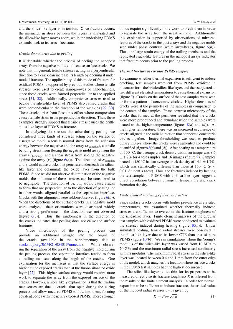
Since surface cracks occur with higher prevalence at elevatedtemperatures, we examined whether thermally inducedstresses are sufficient to overcome the fracture toughness ofthe silica-like layer. Finite element analyses of the circulartest samples with oxidized PDMS were conducted to evaluatethe stresses induced during heating (figure 10(a)). Undersimulated heating, tensile radial stresses were observed inthe silica-like layer due to its lower CTE than that of purePDMS (figure 10(b)). We ran simulations where the Young’smodulus of the silica-like layer was varied from 10 MPa to70 GPa and the maximum radial stress increased nonlinearlywith its modulus. The maximum radial stress in the silica-likelayer was located between 0.4 and 1 mm from the outer edgeof the model, which matches the location where surface cracksin the PDMS test samples had the highest occurrence.
The silica-like layer is too thin for its properties to bemeasured directly so its fracture toughness K is inferred fromthe results of the finite element analysis. In order for thermalexpansion to be sufficient to induce fracture, the critical valueof the induced radial stresses σT is given by
K = FσT
√πa (1)
7

J. Micromech. Microeng. 21 (2011) 054013 W W Tooley et al
where F is the geometric shape factor and a is the length of thepre-crack defect within the structure of the oxidized PDMS[40]. The fracture toughness K of a material under a planestress condition can be related to the strain energy release rateG by
G = K2/E (2)
where E is the material’s Young’s modulus [40]. Forequation (2), the effects of plasticity within PDMS and itsbrittle silica-like layer are considered to be negligible. Anestimate of strain energy release rate of oxidize PDMS hascome from one previous study (G = 0.1–0.3 J m−2) [33], butthe Young’s modulus E has been found to have a wide rangeof values. It has been estimated to be between 11 [34] and220 MPa [20] from indentation tests and between 15 [30] and790 MPa [29] from the analysis of buckled films. The variationin the moduli comes mostly from different oxidizing times andconditions in the formation of the silica-like layer. Together,these estimates give the fracture toughness of the silica-likelayer to be between 0.001 and 0.015 MPa m
12 , which is far
lower than values for fused silica, K = 0.5 MPa m12 , and more
closely resembles the toughness of organo-silicate glass, K =0.01–0.05 MPa m
12 [41].
To examine the thermally induced fracture mechanicsgiven by equation (1), we estimated the length of the pre-crack defects to be 10 nm, since nanoparticles of this size areable to diffuse through pores within PDMS [42, 43]. Since thepre-crack defects are much smaller than the thickness of thesilica-like layer, the geometric shape factor can be assumed tobe unity (F = 1). If a fracture toughness of 0.001 MPa m
12 is
assumed, then a thermal stress greater than 5 MPa would causefracture. Given the results of the finite element simulation,this would require that the Young’s modulus of the silica-likelayer be greater than 100 MPa in order for fracture to occur inthe test samples (�T = 160 K) and 190 MPa for fracture tooccur during casting (�T = 90 K). Likewise, if the silica-likelayer has a higher fracture toughness (K = 0.01 MPa m
12 ),
then its Young’s modulus needs to be greater than 1.2 and2.5 GPa, respectively. Thus, our estimations indicate thatCTE mismatch can cause fracture in oxidized PDMS and thatits Young’s modulus is on the higher end of values previouslyreported.
Conclusion
With this study we have addressed the possibility thatthermal stresses play a significant role in surface crackformation on plasma-oxidized PDMS negative molds duringsoft lithography replication. Negative molds are subjected toboth mechanical and thermal stresses during the fabricationof nanopost arrays. To evaluate the effect of only thermalstrains, studies on thermal expansion were conducted withoutany mechanical factors from peeling or geometry of the array.These studies show that the high CTE of PDMS causes theunderlying layer to exert tensile stresses on the less-compliant,silica-like layer. It is likely that within the oxidized PDMS,there is a distribution in the size of pre-crack defects (a inequation (1)). At the lower temperatures, the corresponding
tensile stress would be strong enough to cause fracture in onlythe largest pre-crack defects. At the highest temperature weexamined (180 ◦C), the tensile stress would be strong enough tofracture both the large and small pre-crack defects and therebylead to the observed increase in crack density with elevatedtemperatures.
This work shows that surface cracks are a concern inthe manufacturability of nanopost arrays because the crackingleads to missing posts. Double-casting is helpful in havingone master template for the post arrays that is then replicatedinto many substrates for biological experiments. It is also costeffective, more efficient, and less wasteful to the environmentto reuse the negative molds. However, the wear on thenegative molds increases with each casting and underminesthe nanoscale pattern fidelity of the replication process. Tomitigate the wear, we recommend using lower temperaturesduring the manufacturing process to reduce the thermallyinduced stresses. Each negative mold should only be used fora few replications of the arrays before discarding it. Direct-casting of PDMS into a master template of holes is a fasterprocess that is mostly fracture free since it does not requireplasma treatment, but it is also susceptible to degradation ofthe expensive silicon molds when PDMS becomes stuck in theholes.
While the scope of our findings pertains mostly tothe fabrication of the nanopost arrays, oxidized PDMS haswidespread use in modifying the surface chemistry of PDMSfor functionalization or bonding layers of PDMS together toform microfluidic channels. Most of the assays or applicationsassociated with PDMS devices are conducted at roomtemperature, but in some instances, elevated temperatures areused, e.g., polymer chain reactions or thermal micropumps.The thermal degradation of the silica-like layer on PDMS canbe detrimental to the usefulness and reliability of these devices.
Acknowledgments
We thank Corey Pollock and Mamidala Ramulu for helpfuldiscussions and assistance and appreciate the generosityof Ana Wieman and the UW Engineering UndergraduateResearch Program. This work was supported in part by fundsfrom the National Science Foundation’s Research Experiencefor Undergraduates (WT), the NSF CAREER Award, and theNational Institutes of Health (HL097284).
References
[1] Xia Y N and Whitesides G M 1998 Soft lithography Angew.Chem. Int. Ed. 37 551–75
[2] Whitesides G M, Ostuni E, Takayama S, Jiang X andIngber D E 2001 Soft lithography in biology andbiochemistry Annu. Rev. Biomed. Eng. 3 335–73
[3] McDonald J C, Duffy D C, Anderson J R, Chiu D T, Wu H,Schueller O J and Whitesides G M 2000 Fabrication ofmicrofluidic systems in poly(dimethylsiloxane)Electrophoresis 21 27–40
[4] Sia S K and Whitesides G M 2003 Microfluidic devicesfabricated in poly(dimethylsiloxane) for biological studiesElectrophoresis 24 3563–76
8

J. Micromech. Microeng. 21 (2011) 054013 W W Tooley et al
[5] Quake S R and Scherer A 2000 From micro- tonanofabrication with soft materials Science 290 1536–40
[6] Ruiz S A and Chen C S 2007 Microcontact printing: a tool topattern Softw. Matter 3 168–77
[7] Sniadecki N J, Desai R A, Ruiz S A and Chen C S 2006Nanotechnology for cell-substrate interactionsAnn. Biomed. Eng. 34 59–74
[8] Lee J N, Jiang X, Ryan D and Whitesides G M 2004Compatibility of mammalian cells on surfaces ofpoly(dimethylsiloxane) Langmuir 20 11684–91
[9] Gomez-Sjoberg R, Leyrat A A, Pirone D M, Chen C Sand Quake S R 2007 Versatile, fully automated,microfluidic cell culture system Anal. Chem. 79 8557–63
[10] Tan J L, Tien J, Pirone D M, Gray D S, Bhadriraju K andChen C S 2003 Cells lying on a bed of microneedles: anapproach to isolate mechanical force Proc. Natl Acad. Sci.USA 100 1484–9
[11] du Roure O, Saez A, Buguin A, Austin R H, Chavrier P,Siberzan P and Ladoux B 2005 Force mapping in epithelialcell migration Proc. Natl Acad. Sci. USA 102 2390–5
[12] Yang M T, Sniadecki N J and Chen C S 2007 Geometricconsiderations of micro- to nanoscale elastomeric postarrays to study cellular traction forces Adv. Mater.19 3119–23
[13] Liang X M, Han S J, Reems J A, Gao D and Sniadecki N J2010 Platelet retraction force measurements using flexiblepost force sensors Lab Chip 10 991–8
[14] Grzybowski B A, Brittain S T and Whitesides G M 1999Thermally actuated interferometric sensors based on thethermal expansion of transparent elastomeric mediaRev. Sci. Instrum. 70 2031–7
[15] Govindaraju A, Chakraborty A and Luo C 2005Reinforcement of PDMS masters using SU-8 trussstructures J. Micromech. Microeng. 15 1303–9
[16] Kunnavakkam M V, Houlihan F M, Schlax M, Liddle J A,Kolodner P, Nalamasu O and Rogers J A 2003 Low-cost,low-loss microlens arrays fabricated by soft-lithographyreplication process Appl. Phys. Lett. 82 1152–4
[17] Fuard D, Tzvetkova-Chevolleau T, Decossas S, Tracqui Pand Schiavone P 2008 Optimization ofpoly-di-methyl-siloxane (PDMS) substrates for studyingcellular adhesion and motility Microelectron. Eng.85 1289–93
[18] Khanafer K, Duprey A, Schlicht M and Berguer R 2009Effects of strain rate, mixing ratio, and stress-straindefinition on the mechanical behavior of thepolydimethylsiloxane (PDMS) material as related to itsbiological applications Biomed. Microdevices 11 503–8
[19] Lotters J C, Olthuis W, Veltink P H and Bergveld P 1997 Themechanical properties of the rubber elastic polymerpolydimethylsiloxane for sensor applications J. Micromech.Microeng. 7 145–7
[20] Bar G, Delineau L, Hafele A and Whangbo M H 2001Investigation of the stiffness change in, the indentationforce and the hydrophobic recovery of plasma-oxidizedpolydimethylsiloxane surfaces by tapping mode atomicforce microscopy Polymer 42 3627–32
[21] Sniadecki N J and Chen C S 2007 Microfabricated siliconeelastomeric post arrays for measuring traction forces ofadherent cells Methods Cell Biol. 83 313–28
[22] Chaudhury M K and Whitesides G M 1991 Directmeasurement of interfacial interactions betweensemispherical lenses and flat sheets ofpoly(dimethylsiloxane) and their chemical derivativesLangmuir 7 1013–25
[23] Chaudhury M K and Whitesides G M 1992 Correlationbetween surface free-energy and surface constitutionScience 255 1230–2
[24] Duffy D C, McDonald J C, Schueller O J A andWhitesides G M 1998 Rapid prototyping of microfluidicsystems in poly(dimethylsiloxane) Anal. Chem. 70 4974–84
[25] Grzybowski B A, Haag R, Bowden N and Whitesides G M1998 Generation of micrometer-sized patterns formicroanalytical applications using a laser direct-writemethod and microcontact printing Anal. Chem. 70 4645–52
[26] Miller D C, Thapa A, Haberstroh K M and Webster T J 2004Endothelial and vascular smooth muscle cell function onpoly(lactic-co-glycolic acid) with nano-structured surfacefeatures Biomaterials 25 53–61
[27] Owen M J and Smith P J 1994 Plasma treatment ofpolydimethylsiloxane J. Adhes. Sci. Technol. 8 1063–75
[28] Befahy S, Lipnik P, Pardoen T, Nascimento C, Patris B,Bertrand P and Yunus S 2010 Thickness and elasticmodulus of plasma treated PDMS silica-like surface layerLangmuir 26 3372–5
[29] Bowden N, Huck W T S, Paul K E and Whitesides G M 1999The controlled formation of ordered, sinusoidal structuresby plasma oxidation of an elastomeric polymer Appl. Phys.Lett. 75 2557–9
[30] Efimenko K, Rackaitis M, Manias E, Vaziri A, Mahadevan Land Genzer J 2005 Nested self-similar wrinkling patterns inskins Nature Mater. 4 293–7
[31] Huh D, Mills K L, Zhu X, Burns M A, Thouless M Dand Takayama S 2007 Tuneable elastomeric nanochannelsfor nanofluidic manipulation Nat. Mater. 6 424–8
[32] Zhu X Y, Mills K L, Peters P R, Bahng J H, Liu E H, Shim J,Naruse K, Csete M E, Thouless M D and Takayama S 2005Fabrication of reconfigurable protein matrices by crackingNat. Mater. 4 403–6
[33] Mills K L, Zhu X Y, Takayama S C and Thouless M D 2008The mechanical properties of a surface-modified layer onpolydimethylsiloxane J. Mater. Res. 23 37–48
[34] Hillborg H, Tomczak N, Olah A, Schonherr H and Vancso G J2004 Nanoscale hydrophobic recovery: a chemical forcemicroscopy study of UV/ozone-treated cross-linkedpoly(dimethylsiloxane) Langmuir 20 785–94
[35] Hillborg H and Gedde U W 1998 Hydrophobicity recovery ofpolydimethylsiloxane after exposure to corona dischargesPolymer 39 1991–8
[36] Song J, Tranchida D and Vancso G J 2008 Contact mechanicsof UV/ozone-treated PDMS by AFM and JKR testing:mechanical performance from nano- to micrometer lengthscales Macromolecules 41 6757–62
[37] Callister W D 2007 Materials Science and Engineering: AnIntroduction 7th edn (New York: Wiley)
[38] Kobayash A S, Wade B G and Maiden D E 1972 Photoelasticinvestigation on crack-arrest capability of a hole Exp. Mech.12 32–7
[39] Murphy D B 2001 Fundamentals of Light Microscopy andElectronic Imaging (New York: Wiley)
[40] Dowling N E 2007 Mechanical Behavior of Materials:Engineering Methods for Deformation, Fracture, andFatigue 3rd edn (Upper Saddle River, NJ: Pearson/PrenticeHall)
[41] Volinsky A A, Vella J B and Gerberich W W 2003 Fracturetoughness, adhesion and mechanical properties of low-kdielectric thin films measured by nanoindentationThin Solid Films 429 201–10
[42] Roman G T and Culbertson C T 2006 Surface engineering ofpoly(dimethylsiloxane) microfluidic devices usingtransition metal sol–gel chemistry Langmuir 22 4445–51
[43] Roman G T, Hlaus T, Bass K J, Seelhammer T Gand Culbertson C T 2005 Sol–gel modifiedpoly(dimethylsiloxane) microfluidic devices with highelectroosmotic mobilities and hydrophilic channel wallcharacteristics Anal. Chem. 77 1414–22
9