J.,ho::;.o. UNITED STATES DEPARTMENT OF THE … RIVER STORAGE PROJECT ... Diversion and Outlet...
57
UNITED STATES DEPARTMENT OF THE INTERIOR BUREAU OF RECLAMATION Tb,omas J. ?,ho::;.o. AIR AND HYDRAULIC MODEL STUDIES OF THE , LEFT DIVERSION TUNNEL OUTLET WORKS FOR GLEN CANYON DAM COLORADO RIVER STORAGE PROJECT...,.,,.ARIZO. NA Hy,drraulie LabGratory Report N,o. Hyd-468 DIVISION OF ENGINEERING LABORATORIES ' ,, . COMMISSIONER'S OFFICE DENVER, COLORADO September 28, 1960
Transcript of J.,ho::;.o. UNITED STATES DEPARTMENT OF THE … RIVER STORAGE PROJECT ... Diversion and Outlet...

UNITED STATES DEPARTMENT OF THE INTERIOR
BUREAU OF RECLAMATION
Tb,omas J. ?,ho::;.o.
AIR AND HYDRAULIC MODEL STUDIES OF THE ,
LEFT DIVERSION TUNNEL OUTLET WORKS
FOR GLEN CANYON DAM
COLORADO RIVER STORAGE PROJECT...,.,,.ARIZO.NA
Hy,drraulie LabGratory Report N,o. Hyd-468
DIVISION OF ENGINEERING LABORATORIES
' ,, .
COMMISSIONER'S OFFICE DENVER, COLORADO
September 28, 1960

CONTENTS
Purpose • • • • • • • • • Conclusions • • • • • • • Acknowledgment • • • • • Intr:oduction • • • • • • • The Models • • • • • • • Investigation • • • • • • •
. . . . . . . . . . . . . . . . . . . . . . . . . . . . .• . . . . . . . . . . . . . . . . . . . . . . . . . . . . . . . . . . . . . . . . . . . . . . . . . . . . . . . . . . .. .. - ,. . ·• .. .
Page
1 1 2 3 4 6
Diversion and Outlet Tunnel Flow Capacities .. • . • • • • 6 Bellmouth Entrance.s.;,-Air Model Studies • • • • • • • • • 7 Co~duit Shape Downstream From Gates • • • . • . . • • 8 Conduit Alinement Downstream From Gate.a • • • • • • • • · 9
Parallel Conduits • • • • . • • • • • • • • • • • Converging Conduits • • • • • • • • • • • • • • Floor Defle-ctor--Center Conduit • • • • . • • • •
. . • • • •
TUilllel Design in Flow Impact Area. • • . . . . . . . . . Air Demand • • • • • • . . . • • • • . . . . . . . Flip Bucket at TUilllel Exit. • • • • . . . . . . . . .
Deflector Walls on the· Bucket • • • • • • • • • • • • Two-stage Bucket Construction. . • • • • • • • , • • Adopted Flip Bucket Design •. •. • • • • • . • • , • • Air Vent. . . . . . . . . . . . . . . . . . . . . . Concrete Pa$g Downstream From Bucket ••••••
Bellmouth Entrances--Hydraulic Model Studies . . . . . . References . . . . . . . . . . . . . . . . . . . . . . . .
9 10 10
11 12 12
13 14 15 15 16
16
17
Sam Peng
Sticky Note
None set by Sam Peng
Sam Peng
Sticky Note
MigrationNone set by Sam Peng
Sam Peng
Sticky Note
Unmarked set by Sam Peng
Sam Peng
Sticky Note
None set by Sam Peng
Sam Peng
Sticky Note
MigrationNone set by Sam Peng
Sam Peng
Sticky Note
Unmarked set by Sam Peng

CONTENTS ( Continued)
I..ocation Map . • . . . • . . . . . . . • . Glen Canyon Dam and Powerplant- -Plan . • • . • Qlen Canyon Dam and Powerplant-:..Elevation and Sections .. Diversion -Tunnels . • . . . . . • • • • . • • • • Left Spillway • • • . • · • • . • . . • • . • . . • • • Left Diversion Tunnel Outlet Works . • • • • • • • • • . • 7. 0- by 10. 5-foot Outlet Gates • • • . • • • . • . • • Model for Tunnel Entrance Calibration. • . • • • Model .for Conduit Bellmouth Studies. . • • • • • • • . . • 1:24 Scale Models for Conduit Bellmouth and Conduit
Alinement Studies • • • • . . • • • • • • • • . . • . • • Water Model for Gate Conduit Shape and AlinementStudies •• Overall Hydraulic Model • . • • • • • • • • • • • • . Model and Prototype Topography at Portal • • • •1 • • • • • Left Diversion Tunnel Trashrack Structure • • • • • • . . • Discharge Curves • • • • • . • • . • • • • • • • • . Flow into Diversion Tunnel Portal • • • • • • • • . • • Pressures on Rectangular Bellmouth Inlets • • . • • • • • • Pressure Factors for Rectangular Bellmouth Inlets • • • • • 7. 0- by 10. 5-foot Outlet Gates Installation • • • • • • . • • Tunnel Flow Conditions--Parallel Conduits--
Equal. Gate Openings • • • • • • • • • • • • • . • • • • Tunnel Flow Conditions--Parallel Conduits--
Left and Right Gates • • • . • • • . . • • • • . . • Tunnel Flow Conditions--Parallel Conduits--Center Gate Tunnell Flow Conditions--Parallel Conduits--
Left and Center . . . . . . . . . . . . . . . . . . . . . Tunnel,Flow Conditions--Parallel Conduits--Left Gate •. Tunnel Flow Conditions--Converged Conduits--
Left and Right Gates • • • . . . . . . . . . . . . • Tunnel Flow Conditions--Converged Conduits--
Floor Deflector . . • . . . . . • . • . . . • • • • • . Pressures at Joint of Plug Section and Tunnel. . • . • • Flip Buckets and Leff Wall .Deflectors . • . . • . • Flow from Flip Bucket--Left Wall Deflected 20. 5 Feet. . . • Flow from Flip Bucket--Left Wall Sloped. . . . . . . • . . Flow from Adopted Bucket--Left Wall Deflected 12. 5 Feet •.• Flow from Adopted Bucket--Left Wall Deflected 12. 5 Feet .•. Flow from Adopted, Bucket--Left Wall Deflected 12. 5 Feet •.. Flow From 1st Stage of Proposed 2 Stage Construction • • . Effect of Air .Vent With Low Velocity Flows Air-Vent for Flip Bucket . . . . . . . . . .
ii
Figure
1 2
.3 4 5 6 7 8 9
10 11 12 13 14 15 16 17
· 18 19
20
21· 22
23 24
25
26 27 28 29 30 31 32 33 34 35 36
Sam Peng
Sticky Note
None set by Sam Peng
Sam Peng
Sticky Note
MigrationNone set by Sam Peng
Sam Peng
Sticky Note
Unmarked set by Sam Peng
Sam Peng
Sticky Note
None set by Sam Peng
Sam Peng
Sticky Note
MigrationNone set by Sam Peng
Sam Peng
Sticky Note
Unmarked set by Sam Peng

UNITED STATES DEPARTMENT OF THE INTERIOR
BUREAU OF RECLAMATION
Commissioner's Office., Denver Laboratory Report No. Hyd-468 Division of Engineering Laboratories Compiled by: W. P. Simmons.,_ Jr. Hydraulic Laboratory Bra:nch Checked by: W. E. Wagner Denver., Colorado Review.ed by: J. _ W. Ball Date: September 28., 1960 Submitted by: H. M. Martin
Subject: Air and hydraulic model studies of the left diversion tunnel outlet works for Glen Canyon Dam--Colorado River Storage Project., Arizona
PURPOSE
The studies were conducted to develop a reliable., trouble-free., highcapacity outlet works design for the left diversion tunnel to control
· releases of water during construction of the dam and during the early period of storage in the reservoir at heads up to 410 feet and discharges up to 32., 700 cfs.
CONCLUSIONS
1~ A satisfactory outlet works can be obtained with 3 conduits spaced 12 feet 6 inches apart and provided with regulating slide gates 7 feet wide by 10 . 5 feet high. (Figure 19)
- 2. Rectangular bellmouth conduit entrances with elliptically curved surfaces provide good boundary surface press~res under all operating conditions (Figures 9 and 17).
3. Steel liners are desirable in the bellmouths and in the conduits leading to the gates.to insure smooth, continuous flow boundaries · free from surface irregularities that could cause local cavitation (Figure 19) .
4. Slide gates of the .type developed for Palisades Dam outlet works 1 / will provide excellent., trouble-free regulation of flow through the -outlet conduits (Figure 7). A guard gate and a service gate of this same basic design will be placed one behind the other in each .conduit.
)
5. -Twenty-four-inch-diameter ducts connected to a 7-foot-wide by 5-foot-high passage leading to the downstream face of the plug., and opening into the 41-foot-diameter tunnel (Figure 6)., will supply adequate air to the top of the conduits just downstream from the control gates. ·
1 / Refers to reference at end of report.
Sam Peng
Sticky Note
None set by Sam Peng
Sam Peng
Sticky Note
MigrationNone set by Sam Peng
Sam Peng
Sticky Note
Unmarked set by Sam Peng
Sam Peng
Sticky Note
None set by Sam Peng
Sam Peng
Sticky Note
MigrationNone set by Sam Peng
Sam Peng
Sticky Note
Unmarked set by Sam Peng

6. The conduits downstream from the gates should be parallel, horizontal, 7 feet wide, 14. 5 feet high and free from surface irregularities that could produce cavitation (Figure 6). Steel lining.extending a:cross the floor and 13 feet up the walls is desirable.
7 . A deflector 6 feet long and 6 inches high, on the floor at the downstream end of the center conduit, will direct that outlet's flow on a longer trajectory to produce better fl.ow conditions in the downstream tunnel (Figure 11).
8 . Better flow conditions occur in the tunnel if the keyway or conic tunnel plug section is replaced by straight 41-foot-diameter tunnel. This alternative is costly and not justified by the moderate improvement in performance. The keyway section, which is needed for strength in the final tunnel closure# should remain as originally proposed.
9. Unsymmetrical fl.ow releases from the three outlets result in sideto-side swinging flow in the circular tunnel (Figures 23 and 24). This swinging persists to the outlet portal. No difficulty occurs in the tunnel due to this action.
10. Swinging flow affects the direction in which water leaves the flip bucket at the tunnel portal, and under some operating conditions, water strikes the lower portions of the left canyon wall (Figures 2 9-34) .
11. Deflecting the left wall of the flip bucket to the right tends to prevent water from striking the canyon wall (Figures 29-34). A 20. 5-foot deflection works well for all symmetrical and unsymmetrical outlet flows, but is too severe for the larger spillway flows. A sloped left wall of less deflection keeps almost all the w~ter off the canyon wall, but is _ unsatisfactory with spillway flows. A 12. 5-foot deflection with a vertical wall allows an appreciable portion of the water .to strike the lower canyon wall during certain outlet flows, but is ideal for spillway flows.
12. Constructing the flip bucket in two stages, with only part of the curved invert present during outlet releases, does not significantly· decrease the amount or intensity of water impingement on the canyon wall with either symmetrical or unsymmetrical flows approaching the bucket.
13. The full bucket with the left wall vertical and deflected 12. 5 feet at the downstream end may be used for both outlet works and spillway releases. Water .will impinge on the lower canyon wall during small outlet releases (Figures 31-33). The impingement will be greatest with certain unsymmetrical flows, and s:u~h operation is to be avoided wherever possible.
ACKNOWLEDGEMENT
The outlet works design ·evolved for final use was obtained through close cooperation between engineers in the Mechanical and Dams
2
Sam Peng
Sticky Note
None set by Sam Peng
Sam Peng
Sticky Note
MigrationNone set by Sam Peng
Sam Peng
Sticky Note
Unmarked set by Sam Peng
Sam Peng
Sticky Note
None set by Sam Peng
Sam Peng
Sticky Note
MigrationNone set by Sam Peng
Sam Peng
Sticky Note
Unmarked set by Sam Peng

Branches of the Division of Design, and the Hydraulic Laboratory Branch of the Division of Engineering Laboratories, Denver, Colorado.
INTRODUCTION
Seven hundred and ten feet high, 1,400 feet long at the crest, and standing across the Colorado River in Arizona 13 miles south of the Utah border, Glen Canyon Dam constitutes the principal feature in the farreaching Colorado River Storage Project (Figure 1). It is a massive concrete arch structure founded on sandstone and impounds a reservoir with a surface area up to 164,000 acres and a capacity of 28 million acre-feet (Figures 2 and 3). The reservoir, when full, will extend 186 miles up the Colorado River and 71 miles up the San Juan. The water will be used for irrigation and domestic purposes, for industrial and mineral development in the region, and for the development of power at the dam's 8-unit 930, 000-kw powerplant. Other l,)enefits such as flood control and recreation will also be enjoyed. ·
During early construction of the dam, the river will be diverted through two 41-foot-diameter concrete-lined diversion tunnels. One tunnel, with the inlet invert at elevation 3136 .10, passes around the damsite through the right canyon wall (Figure 4). The other, with the inlet invert at elevation 3171 . 2 5, passes through the left wall. After construction of the dam has advanced sufficiently, the upstream portions of these diversion tunnels will be abandoned and permanent seals, or plugs, will be installed to close them (Figures 3 and 5). The downstream portions will then be connected to the spillway tunnels that slope down to meet them, thereby completing the reservoir spillway facilities (Figures 3 and 5).
From practical and economic· points of view, water storage should start as soon as the water is available and sufficient construction has been achieved. During such storage, water must be released through or around the dam to meet previous commitments. To fulfill these conditions, some form of outlet works must be provided. Unfortunately, due to the relative narrowness of the canyon and the appreciable space requirements of the penstocks, the inlets to the river outlets must be placed at elevation 3374 (Figure 3). This means that a lake 265 feet deep must be impounded before the river outlets can release water. They therefore cannot be used to make releases during the early reservoir storage period.
To provide the necessary river control for the interim period, an outlet structure will be built into the left diversion tunnel plug (Figures 4 and 6) . It consists of three 7 -foot wide by 10. 5-foot high rectangular passages in the plug, followed by the same size high-head slide gates and by 7-foot wide by 14. 5-foot high conduits that discharge into the downstream tunnel. Bellmouth inlets are provided at the conduit entrances in the upstream face of_the plug. An emergency gate and a service gate are provided one behind the other in each conduit. The gates are of the slide type
. (Figure 7) developed and used successfully at Palisades Dam for a number of years at various gate openings with heads up t~ 200 feet.
3
Sam Peng
Sticky Note
None set by Sam Peng
Sam Peng
Sticky Note
MigrationNone set by Sam Peng
Sam Peng
Sticky Note
Unmarked set by Sam Peng
Sam Peng
Sticky Note
None set by Sam Peng
Sam Peng
Sticky Note
MigrationNone set by Sam Peng
Sam Peng
Sticky Note
Unmarked set by Sam Peng

The tunnel plug outlet works will be constructed during the low flow period in the fall and winter of 1961-62. During this construction, all of the river flow will be diverted past the dam site through the right diversion tunnel. After the construction is completed, massive reinforced concrete gates will be lowered and permanently sealed in the right diversion tunnel entrance to close it permanently. After this closure, and up to the time the lake has risen enough, and overall construction has advanced enough, all flows past the dam must be released
· by the left diversion tunnel outlet works .
The importance of reliable, continuous, trouble-free operation of this tunnel outlet works is apparent. Proper releases of water for downstream commitments depend upon it functioning without a falter for the time needed to bring the reservoir up to working level. This length of time depends upon how much water is available for storage and upon how rapidly construction advances on tne dam and related structures. Estimates of the time range from a minimum of 3 years to a probable maximum of 7 years. After the reservoir reaches a service level and the river outlet works and turbines can be operated, the tunnel outlet gates will be closed and the conduits filled and sealed with concrete. The remaining section of tunnel plug will then be installed to complete the plug and permanently seal the upstream part of the tunnel. The final connection to the left spillway tunnel can then be made (Figure 5).
The need for long-term satisfactory outlet works performance made model studies very desirable. By means of these studies hydraulic deficiencies could be discovered and corrected and the best possible combination of reliable, trouble-free operation and construction economy could be obtained. The model studies were therefore made, and a discussion. of the studies and their results is presented in this report.
THE MOOELS
Three models were used in the various tests of the overall tunnel and outlet works systems. The first tests cpncerned the relationship of reservoir head to rate of flow into the diversion tunnel. A simplified 1:41 scale model was used for the tests (Figure 8) ·. It consisted of a water supply, a head box 4 feet wide by 7 feet long, a sloping plywood headwall that represented the talus slope at the tunnel entrance, the .short excavated inlet channel, the concreted tunnel entrance, the tra.shrack frame, and the tunnel bend. A sheet metal slide gate at the end of the tunnel section regulated the depth of flow in part of the tests.
The second tests were made to .study bellmouth shapes for the entrances to the three dU.tlet conduits. Air was used as the flowing fluid and a 1:24 scale model was constructed (Figures 9 and l0A). The model components were made of soldered light gage galvanized sheet metal. A pipe 60 inches long and_ 20. 5 inches in diameter represented the 41-foot-diameter tunnel upstream from the plug. Three 3. 5-inch wide by 5.25-inch high conduits represented the prototype 7-foot wide.by 10. 5-foot high conduits. Sheet" metal gates at the downstream end of
4
Sam Peng
Sticky Note
None set by Sam Peng
Sam Peng
Sticky Note
MigrationNone set by Sam Peng
Sam Peng
Sticky Note
Unmarked set by Sam Peng
Sam Peng
Sticky Note
None set by Sam Peng
Sam Peng
Sticky Note
MigrationNone set by Sam Peng
Sam Peng
Sticky Note
Unmarked set by Sam Peng

the model conduits enabled various gate openings to be set. The model sections were placed on the inlet of a conventional centrifugal blower so air was drawn from the atmosphere into the model. The rate of air flow was measured by flat plate orifices placed on the end of the 10-inchdiameter blower outlet pipe. A 20-horsepower electric motor drove the blower.
One-sixteenth-inch-diameter piezometers were provided in critical areas on the bellmouths (Figure 9). Care was taken to make these openings normal to the flow surface, flush, burr-free, and without change in direction or dimension for a distance of at least 3/16 inch (three opening diameters) from the surface. This is in accord with usual piezometry requirements 2/ .and was achieved by extending 1/16-inch-inside-diameter brass tubes through the sheet metal walls, soldering them in place, a:nd cutting, trimming and then smoothing them to conform to the flow surfaces. The pressures measured by the piezometers were read on U-tubes filled with water. Readings were estimated to the nearest one-hundredth of an inch.
A 1:24 scale hydraulic model was used for a third test series to determine the conduit alinement needed downstream from the gates to obtain satisfactory tunnel flow conditions. Three outlet conduits with regulating gates were connected with flexible hoses to a water supply manifold (Figures l0B and 11). Transparent plastic was used for the con~uits downstream from the gates so the flow could be visually studied. The final tunnel plug keyway section was represented by a portion of a:
. cone. A semicircular .sheet metal trough 20. 5 inches in diameter and 24 fe~t long represented the tunnel. A semicircular transparent plastic cover 12 feet long completed the tunnel section near the gates.. The remainder of the tunnel top was left open. Pi.ezometers were provided in the outlet works conduits just upstream from the gates so·that the pressure heads could be measured and appropriate operating heads could be set on the model.
Water was supplied to the model by 12-inch centrifugal pumps contained in the central laboratory water supply system. Calibrated venturi meters in the piping system provided the means for measuring rate of flow. The water returned to the laboratory reservoir and was recirculate~ after passing through the model.
The tests for conduit alinement showed that unsymmetrical operation of the gates produced a side-to-side .swinging flow in the tunnel. Thus, under certain conditions, flow approached the flip bucket at the end of the tunnel with a sideward component and struck the canyon wall. The nature of the sandstone in_ the canyon wall with its open cracks or seams · lying in line with the fiow m,ade this possibility unattractive. To deter-
. mine the flow conditions in the region of the bucket, and to determine the final overall performance of the tunnel and outlet system., another 1:24 scale model was ·assembled (Figure 12). This model consisted of a 12-inch supply from the laboratory water system., an expanding section to a 20. 5-inch-diameter 6-foot 10-inch long pipe., the tunnel plug bellmouth inlet and conduit section, the control gates, the downstream
5
Sam Peng
Sticky Note
None set by Sam Peng
Sam Peng
Sticky Note
MigrationNone set by Sam Peng
Sam Peng
Sticky Note
Unmarked set by Sam Peng
Sam Peng
Sticky Note
None set by Sam Peng
Sam Peng
Sticky Note
MigrationNone set by Sam Peng
Sam Peng
Sticky Note
Unmarked set by Sam Peng

conduits, the downstream tunnel, the flip bucket, and the topography at the tunnel portal. The bellmouth inlet and conduit section was the same one used in the air tests. The lightly built sheet metal components of this section required reinforcement to withstand the higher loads imposed by the water model. This was achieved by encasing the entire section in concrete while not disturbing the piezometer tubes or flow surfaces. By this means it became possible to obtain both air and water data on the same section, thereby obtaining a direct and interesting comparison of results.
The 44-foot long section of tunnel extending from the outlet conduits to the flip buck of the overall model was shorter than the 53-foot length obtained by scaling down the prototype tunnel. This difference in length had no significant effect on the'test results, as will be discussed later in the report. A gaging station installed near the end of the tunnel just upstream from its connection with the flip bucket enabled measurement of the flow velocities entering the bucket.
The model bucket was made of 1/16-inch thick sheet metal accurately formed to shape and soldered. Piezometers were provided for measurement of significant pressures.
The topography in the. tail box was produced by placing horizontal wooden contour line templates at appropriate elevations within the box, covering them with metal lath, and applying a 1/2-inch thick coat of sand-cement concrete. Final details of the canyon wall were hand molded using field · measurements and photographs as guides (Figure 13).
INVESTIGATION
Diversion and Outlet Tunnel Flow Capacities .
. At very low reservoir elevations small flows will enter the left diversion tunnel (Figure 14). With such small flows, and with the outlet gates open and at a considerably lower elevation than the inlet, the flow control point will occur at the tunnel entrance. Critical flow is expected just inside the tunnel. Computations to determine the flow rates at given reservoir elevations would, to a great extent, depend upon assumed loas values for the inlet structure. Information on these· values for these particular conditions was meager and model studies were made to obtain the relationship of water surface elevation to rate of flow.
The topography of the talus slope and the ·excavation through it to the tunnel entrance were not known with precision at the time the tests were made. Specific details were therefore not included in the model. However, the general features of the slope and excavated channel were represented by surfaces formed of plywood. The prototype tunnel entrance ls rounded, starting with a 3 ~foot 6-inch radius at the crown and progressively decreasing to a 6-inch radius at the horizontal diameter, and continuing with the 6-inch radius to the invert (Figure 14).
6
Sam Peng
Sticky Note
None set by Sam Peng
Sam Peng
Sticky Note
MigrationNone set by Sam Peng
Sam Peng
Sticky Note
Unmarked set by Sam Peng
Sam Peng
Sticky Note
None set by Sam Peng
Sam Peng
Sticky Note
MigrationNone set by Sam Peng
Sam Peng
Sticky Note
Unmarked set by Sam Peng
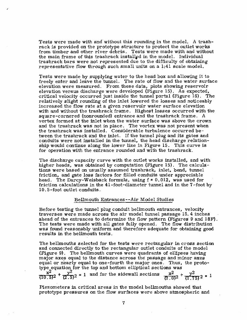
Tests were made with and without this rounding in the model. A trashrack is provided on the prototype structure to protect the outlet works from timber and other river debris. Tests were made with and without the main frame of this trashrack insta~d in the model. Individual trashrack bars were not represented due to the difficulty of obtaining representative flow through such small units on a ~:41 scale model.
Tests were made by .supplying water to the head box and allowing it to freely enter and leave the tunnel. The rate of flow and the water surface elevation were measured. From these data., plots showing reservoir elevation versus discharge were developed (Figure 15). As expected., critical velocity occurred just inside the tunnel portal (Figure 16). The relatively slight rounding of the inlet lowered the losses and noticeably increased the flow rate at a given reservoir water surface elevation with a,nd without the trashrack frame. Highest losses occurred with the square-cornered (nonrounded) entrance and the trashrack frame. A vortex formed at the inlet when the water surface was above the crown and the trashrack was not in place. The vortex was not present when the trashrack was installed. Considerable turbulence occurred between the trashrack a·nd the inlet. If the tunnel plug and its gates and conduits were not installed in the tunnel, the head discharge relationship would continue along the lower line in Figure 15. This curve is for operation with the entrance rounded and with the trashrack.
The discharge capacity curve with the outlet works installed., and with higher heads., was obtained by computation (Figure 15). The calculations were based on_usually assumed trashrack., inlet, bend., tunnel friction., and gate loss factors for filled conduits under appreciable head. The Darcy-Weisback formula, using f = 0.012, was used for friction calculations in the 41-foot-diameter tunnel and in the 7-foot by 10. 5-foot outlet conduits.
Bellmouth Entrances--Air Model Studies
Before testing the tunnel plug conduit bellmouth entrances., velocity traverses were made across the air model tunnel passage 15. 4 inches ahead of the entrances to determine the flow pattern (Figures 9 and 18F). The tests were made with all gates fully opened. The flow distribution was found- reasonably uniform and therefore adequate for obtaining good results in the bellmouth tests.
The bellmouths selected for the tests were rectangular in cross section and connected directly to the rectangular outlet conduits of the model (Figure 9). The bellmouth curves were quadrants of ellipses having major axes equal to the distance across the passage and minor axes . equal or nearly equal to one-fourth the major ones. Thus., the prototype equation for the top and bottom elliptical sections was .,.,,.,_x .... 2.,..2 + .......I:..2 = 1 and for the sidewall sections x2 2 + _E_2 _ 1 cto. 5) 12 ~ 5) (1. o) cr~aJ -Piezometers in critical areas in the model bellmouths showed that prototype pressures on the flow surfaces were above atmospheric and
7
Sam Peng
Sticky Note
None set by Sam Peng
Sam Peng
Sticky Note
MigrationNone set by Sam Peng
Sam Peng
Sticky Note
Unmarked set by Sam Peng
Sam Peng
Sticky Note
None set by Sam Peng
Sam Peng
Sticky Note
MigrationNone set by Sam Peng
Sam Peng
Sticky Note
Unmarked set by Sam Peng

therefore satisfactory during operation with all gates fully opened (Figure 17A). Similarly, all pressures were satisfactory with any 2 gates fully opened and the other one fully closed (Figure 17 A). The closed. gate could be either a side gate or the center gate. Also, satisfactory pressures occurred when any one gate was operated fully opened and the other 2 gates were fully closed (Figure 17 A). Partially opened gates produced higher pressure gradients in the conduits and higher pressures on the bellmouth surfaces than full gate openings . Such operation was therefore satisfactory. It was concluded that the initial design for the rectangular bellmouth entrances was entirely satisfactory and should be used in the prototype structure. The pressure data, expressed in,. the more generally usable form of a dimensionless pressure factor, -~-h-, are given in Figure 18. In this .
hv pressure factor, ~h equals the piezometric pressure referred to the conduit centerline minus the conduit centerline pressure at the down-
-2 stream end of the bellmouth, and hv equals the velocity head~ .., of the flow in the conduit. g
Although the bellmouth shapes produced greater than atmospheric pressures on the flow surfaces, small surface irregularities and roughnesses could cause local regions of su.batmospheric pressure and cavitation. To guard against such surface roughnesses in the final passage, and thus to avert any localized cavitation, steel lining will be _u-sed in the bellmouth sections and in the conduits to the gates (Figure 19). By this means, carefully curved, long-lived, smooth flow surfaces will be maintained. ·
Conduit Shape Downstream From Gates
The cross-sectional shape and height of the conduits downstream from the regulating gates was important in that they must provide sufficient space for air above the jet. Alinement of the conduits and gates was important to minimize splashing and turbulence in the downstream tunnel where the outlet flows strike.
A 'hydraulic model with flexible connections upstream from the control gates and transparent conduits downstream from the gates was used for the tests (Figures lOB and 11). The initial 7. 5-foot-wide by 12. 5-foothigh conduits were found adequate for flows at partial gate openings, but lacking in sufficient height for flows at full openings. This occurred because the flow leaving the 10. 5-foot-high gates slowed and became deeper as it traveled downstream through the conduits. At the same time, air mixed with the water at the top of the jets and further increased their depths. As a result, the 12. 5-foot-high conduits tended to fill at the downstream end,. thereby occasionally.,. but very abruptly, changing the hydraulic conditions in the conduits and gates, anddrastically lowering the pres.sure .gradients. To alleviate this condition, the roofs of the conduits were sloped upward from the 12. 5-foot height at the gates to a:.14. 5-foot height at the downstream ends (Figure. 11). This allowed adequate space for aeration above the expanded jets. However, the
8
Sam Peng
Sticky Note
None set by Sam Peng
Sam Peng
Sticky Note
MigrationNone set by Sam Peng
Sam Peng
Sticky Note
Unmarked set by Sam Peng
Sam Peng
Sticky Note
None set by Sam Peng
Sam Peng
Sticky Note
MigrationNone set by Sam Peng
Sam Peng
Sticky Note
Unmarked set by Sam Peng

sloping roof of this design required special forming during construction. A design with a uniform height of 14. 5 feet was therefore suggested (Figure 11). The final design, as used in the prototype structure, uses the 14. 5-foot-high conduit with 18-inch, 45° fillets in the top corners (Figures 6 and 19).
Steel lining will be placed on the conduit floors and walls downstrea:in from the gates (Figure 19) to insure smooth, straight surfaces without discontinuities that might induce local pressure reductions and cavitation_. These smooth, straight walls and the slide gate design already proved satisfactory at Palisades Dam are expected to produce reliable, troublefree service.
Conduit Alinement Downstream From Gates
Parallel Conduits
The conduits were first placed horizontal, parallel, and 12 feet 6 inches apart on center lines for ease of accommodation in the plug (Figure 11). Tests showed that acceptable flow conditions occurred in the tunnel when the three gates were operated at equal openings ( Figure 20). At a 100-foot head with the gates full open, the center jet struck the tunnel invert fairly well downstream from the tunnel plug section (Station 23+78. 20) (Figure 12). The side jets struck partly on the joint at Station 23+78. 20. Heavy splash occurred, rising above the tunnel center line. At a 100-foot head and 75 percent gate openings, the impact points were the same as those observed at 100 percent gate opening. Splash continued between the jets, rising to about 60 percent of the tunnel height. At a 200-foot head, the center impact point with 100 percent and 75 percent gate openings was about 25 feet past the tunnel joint. At a 350-foot head, it was 60 feet downstream. Conditions for 50 and 25 percent gate openings were generally similar to those for larger gate openings but there was less splashing and spray.
When the center gate was closed and flow maintained through the two side gates, a large fin formed in the center of the tunnel where the jets came down the sides of the passage. and collided (Figure 21). This fin rose to the crown of the tunnel with low heads and large gate openings and wavered from side to side. The fin peaked at Station 24+58 with a 100-foot head and at Station 24+92 with a 350-foot head.
Operation with just the center gate produced fins that flowed up each side of the tunnel ( Figure 22). The action was particularly severe at low heads when the fins were somewhat unstable and rose higher first on one side of the conduit and then on the other side. No regular periodicity was not~d. Farther downstream, the side fins were drawn downward by gravity and collided to form a large central fin. This, in turn, was transformed back into side fins, etc. The phenomena repeated several times with only slight attenuation in the length of the model conduit.
9
Sam Peng
Sticky Note
None set by Sam Peng
Sam Peng
Sticky Note
MigrationNone set by Sam Peng
Sam Peng
Sticky Note
Unmarked set by Sam Peng
Sam Peng
Sticky Note
None set by Sam Peng
Sam Peng
Sticky Note
MigrationNone set by Sam Peng
Sam Peng
Sticky Note
Unmarked set by Sam Peng
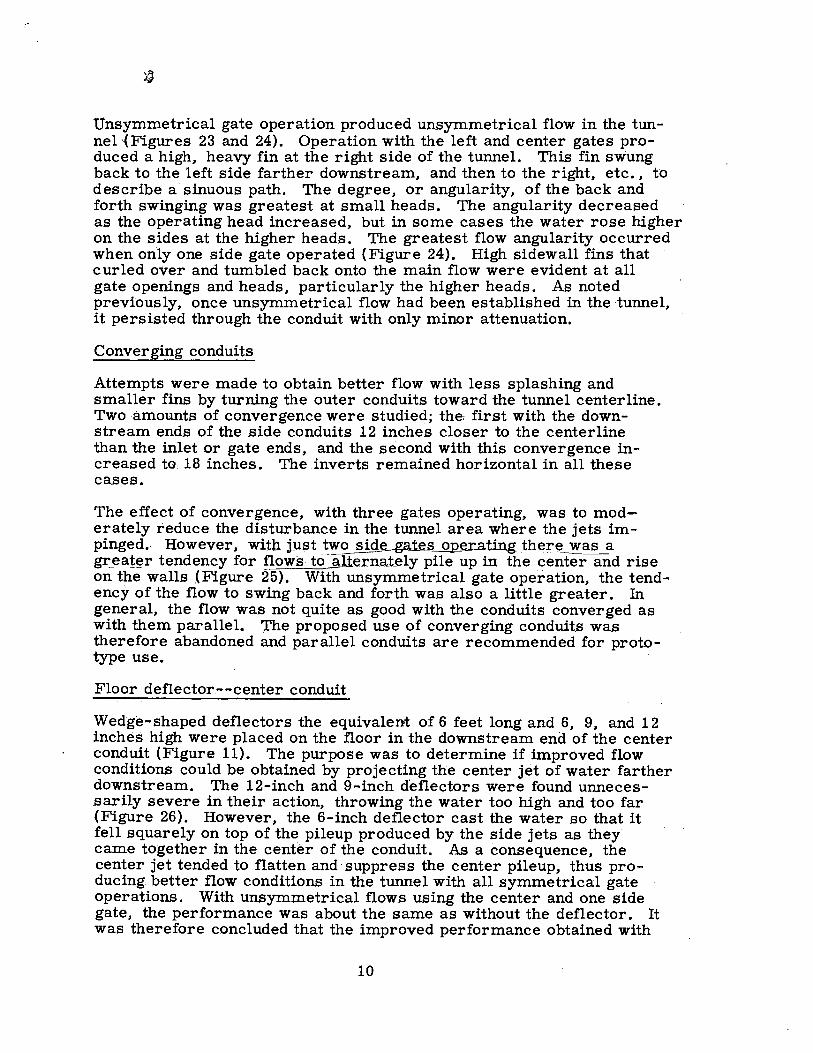
Unsymmetrical gate operation produced unsymmetrical flow in the tunnel·{ Figures 23 and 24). Operation with the left and center gates produced a high, heavy fin at the right side of the tunnel. This fin swung back to the left side farther downstream, and then to the right, etc •• to describe a sinuous path. The degree. or angularity. of the back and forth swinging was greatest at small heads. The angularity decreased as the operating head increased, but in some cases the water rose higher on the sides at the higher heads. The greatest flow angularity occurred when only one side gate operated {Figure 24). High sidewall fins that curled over and tumbled back onto the main flow were evident at all gate openings and heads, particularly the higher heads. As noted previously, once unsymmetrical flow had been established in the tunnel, it persisted through the conduit with only minor attenuation.
Converging conduits
Attempts were made to obtain better flow with less splashing and smaller fins by turning the outer conduits toward the tunnel centerline. Two -amounts of convergence were studietj; the: first with the downstream ends of the side conduits 12 inches closer to the centerline than the inlet or gate ends, and the second with this convergence increased to: 18 inches. The inverts remained horizontal in all these cases.
The effect of convergence, with three gates operating, was to moderately reduce the disturbance in the tunnel area where the jets impinged. However, witn_just two side gates operating _th~!"e was a g;r:ea!~r te_ndency for flows- to-alt.ernat.ely pile up in the center and rise on the walls (Figure 25). With unsymmetrical gate operation, the tendency of the flow to swing back and forth was also a little greater. In general, the flow was not quite as good with the conduits converged as with them parallel. 'l'he proposed use of converging conduits was therefore abandoned and parallel conduits are recommended for prototype use.
Floor deflector.--center conduit
Wedge-shaped deflectors the equivalent of 6 feet long and 6, 9, and 12 inches high were placed on the floor in the downstream end of the center conduit (Figure 11). The purpose was to determine if improved flow conditions could be obtained by projecting the center jet of water farther downstream. The 12-inch and 9-inch deflectors were found unnecessarily severe in their action, throwing the water too high and too far (Figure 26). However, the 6-inch deflector cast the water so that it fell squarely on top of the pileup produced by the side jets as they came together in the center of the conduit. As a consequence, the ce.nter jet tended to flatten and· suppress the center pileup, thus producing better flow conditions in the tunnel with all symmetrical gate operations~ With unsymmetrical flows using the center and one side
· gate, the performance was about the same as without the deflector. It was therefore concluded that the improved performance obtained with
10
Sam Peng
Sticky Note
None set by Sam Peng
Sam Peng
Sticky Note
MigrationNone set by Sam Peng
Sam Peng
Sticky Note
Unmarked set by Sam Peng
Sam Peng
Sticky Note
None set by Sam Peng
Sam Peng
Sticky Note
MigrationNone set by Sam Peng
Sam Peng
Sticky Note
Unmarked set by Sam Peng
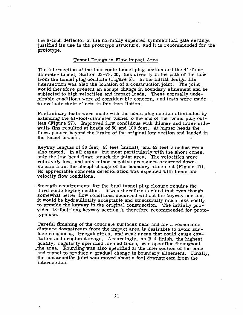
the 6-inch deflector at the normally expected symmetrical gate settings justified its use in the prototype structure, and it is recommended for the · prototype.
Tunnel Design in Flow Impact Area
The intersection of the last conic tunnel plug section and the 41-footdiameter tunnel, Station 23+7 8. 20, lies directly in the path of the flow from the tunnel plug conduits (Figure 6). In the initial design this intersection was also the location of a construction joint; The joint would therefore present an abrupt change in boundary alinement and be subjected to high velocities and impact loads. These normally undesirable conditions were .of considerable concern, and tests were made to evaluate their effects in this installation.
Preliminary tests were made with the conic plug section eliminated by extending the 41-foot-diameter tunnel to the end of the tunnel plug outlets (Figure 27). Improved flow conditions with thinner and lower sidewalls fins resulted at heads of 50 and 100 feet .. At higher heads the flows passed beyond the limits of the original key section and landed in the tunne 1 proper.
Keyway lengths of 30 feet, 43 feet (initial), and 49 feet 6 inches were also tested. In all cases, but most particularly with the short cones, only the low-head flows struck the joint area. The velocities were relatively low, and only minor negative pressures occurred downstream from the abrupt change of the boundary alinement (Figure 27). No appreciable concrete deterioration was expected with these low velocity flow conditions.
Strength requirements for the final tunnel plug -closure require the third conic keying section. It was therefore decided that even though somewhat better flow conditions occurred without the keyway section, it would be hydraulically acceptable and structurally much less costly to provide the keyway in the original construction. The initially provided 43-foot-long keyway section is therefore recommended for prototype use.
Careful finishing of the concrete surfaces near and for a reasonable distance downstream from th~ impact area is desirable to avoid surface roughness, irregularities, and weak areas that could cause cavitation and erosion damage. Accordingly, an F-4 finish, the highest quality, regularly specified formed finish, was specified throughout
.the area. Rounding was also specified at the intersection of the cone and tunnel to produce a gradual change in boundary alinement. Finally, the construction joint was moved about a foot downstream from the intersection.
11
Sam Peng
Sticky Note
None set by Sam Peng
Sam Peng
Sticky Note
MigrationNone set by Sam Peng
Sam Peng
Sticky Note
Unmarked set by Sam Peng
Sam Peng
Sticky Note
None set by Sam Peng
Sam Peng
Sticky Note
MigrationNone set by Sam Peng
Sam Peng
Sticky Note
Unmarked set by Sam Peng

Air Demand l~'!
Air must .be admitted into the outlet conduits just downstream from the · gates to insure that flow will occur with a free water surface in the conduits at all gate openings and to meet the air entrainment requirements. Adequate air (and tunnel dimensions) will prevent flow changes from free discharge conditions to fully filled conditions as gate openings approach 100 percent. Such changes in flow conditions are usually un- • desirable because they abruptly change the trajectory and nature of the · flow, adversely affect the regime into which the gates discharge, and · ower the pressure gradient at the gate and in the conduit to greatly ncourage cavitation and damaging erosion.
To provide adequately sized ducts to supply this air, computations were made of the expected demand. The procedure used is based on a elationship of air demand versus Froude n1J.mber of the emerging jet t the vena contracta 4/. Substitution of the 7-foot by 10. 5-foot dimenions and the 410-foofbead of the Glen Canyon gates into the relationhip produced a maximum predicted air demand of 2, 175 cfs per gate.
This compares favorably with the 2, 120 cfs discharge predicted by in:.. creasing on an area basis the 1,300 cfs measured air demand of the 5-oot by 9-foot sluice gates .at Pine Flat Dam under a 370-foot head 3/.
Normally flow velocities lower than 300 fps are desired in air ducting o outlet valves to minimize noise and any possibility of danger to
personnel at the duct inlet. On this basis a duct 36 inches in diameter would be required for each gate. Space and structural limitations within he cramped confines of the tunnel plug made this size difficult, and a 24-inch-diameter duct at each gate was us.ed instead (Figures 6 and 19). This will pro.duce a 690-fps velocity if the maximum air demand of 2, 175 cfs is attained. Actually, such a demand is unlik~ly because the 10-foot required head will probably not occur during the operating ·
period of the tunnel plug outlet works. The 24-inch-diameter ducts are ample for all likely demands for air. They are co;nsidered satisactory for the very high release.s because noise is not a factor in the emote area of this outlet works. Also, the element of danger is nonxistent because the inlet to the 7-foot-wide by 5-foot-high air passage upplying the three 24-inch ducts is in the downstream top portion of he plug and thus beyond the reach of operating personnel (Figure 6).
Flip Bucket at Tunne 1 Exit
The tendency for :flows to swing from side to side in the tunnel when unsymmetrical conditions have been set up by unequal gate openings was discussed. The swinging is undesirable because it allows water o enter the flip bucket, at the end of the tunnel with a definite sideward
velocity component. This component may .carry the flow to the right toward the center of the river or to the left toward the canyon wall,· depending on the position of the swinging flow as it approaches the bucket (Figure 12). Unfortunately the sandstone canyon walls above elevation 3155 contain vertical joints or cracks that lie in line ~ith the flowing water. It is therefore best that the canyon wall not be subjected to heavy sustained water impact.
12
Sam Peng
Sticky Note
None set by Sam Peng
Sam Peng
Sticky Note
MigrationNone set by Sam Peng
Sam Peng
Sticky Note
Unmarked set by Sam Peng
Sam Peng
Sticky Note
None set by Sam Peng
Sam Peng
Sticky Note
MigrationNone set by Sam Peng
Sam Peng
Sticky Note
Unmarked set by Sam Peng

To investigate whether or not heavy impact would occur on the wall, and to develop corrective measures to prevent or control such impact, additional model studies were made. A tail box containing the outlet flip bucket and canyon wall was added to the model, and the tunnel section was made 44 feet long (Figure 12). Actually, a 55-foot long tunnel was needed to represent the full 1, 316-foot prototype tunnel, but this length could not be used because of laboratory space limitations. The shorter length was not critical in subsequent tests because the pattern of swinging could be easily adjusted by selective gate .settings and operating heads. This allowed any type or direction of swinging to be produced at the flip bucket and any prototype condition could be represented.
The basic bucket used in the tests was the design found best for spillway operation (Figures 12 and 28). The development of this bucket and its performance with spillway flows is discussed in Report No. Hyd-469 5/. A large deflector is incorporated in the left side of the bucket to throw water away from the left canyon wall and into the river channel. Changes in this deflector and in the bucket floor were .studied in the outlet works test.
Deflector Walls on the Bucket
Three series of tests were made, each with a different degree of deflection in the left wall of the bucket (Figure 28). In the first the downstream 70 feet of the wall was angled to the right so that it reached the conduit centerline (Figure 28B). This was equivalent to a prototype deflection of 20. 5 feet. The wall was vertical.
This bucket and deflector design was quite effective in keeping outlet flows away from the canyon wall ( Figure 29). Even with the most adversely swinging flows entering the bucket, the water was thrown clear of the rock. However, the flow was rough and ro.se in a rather narrow and very high jet during high head releases. Furthermore, tests made in the 1:64 scale, spillway model 5/ showed that this amount of deflection was too much for large spillway flows.
The second test series was made using less deflection on the bucket wall. Experience suggested that it was desirable to retain heavy de':"' flection at the bottom of the wall to intercept the main stream that tended to pass under water already turned. Somewhat less deflection at the top of the wall was expected to produce a broader and lower jet. The wall was, therefore, made with a sloped surface starting at Station 37+26. 00 and terminating at Station 37+96. 00 (Figure 28B). The bottom of the wall at Station 37+96. 00 was set 20. 5 feet to the right to coincide with the conduit center line. The top was set over 12. 5· feet. This sloped surface intersected the vertical surface of the original wall of the basic bucket.
The sloped deflector wall was less effective in turning the water into the river channel than the vertical 20. 5-foot deflected wall, and some of the flow plunged down onto the lower portions of the canyon wall (Figure 30). The impact was greatest when unsymmetrical flows
13
Sam Peng
Sticky Note
None set by Sam Peng
Sam Peng
Sticky Note
MigrationNone set by Sam Peng
Sam Peng
Sticky Note
Unmarked set by Sam Peng
Sam Peng
Sticky Note
None set by Sam Peng
Sam Peng
Sticky Note
MigrationNone set by Sam Peng
Sam Peng
Sticky Note
Unmarked set by Sam Peng

entered the flip bucket. At all heads, discharges, ~nd gate openings, the jet was broader and not as high as the jet fr9m the first bucket. Considerable roughness persisted. ·
The third test serie.s was made with the bucket wall vertical and deflected 12. 5 feet at the downstream end, i.e., the original wall of the basic bucket (Figure 28A). This corresponds to the design found best for spillway flows. Even with symmetrical nonswinging flows entering , the bucket, the deflector wall did not turn the flow sufficiently to keep . it off the canyon wall (Figure.a 31, 32, and 33). As a result, appreciable impact occurred low on the wall, particularly at heads of about 150 to 200 feet. No significant impact occurred high on the canyon wall. At increased heads. the flows traveled farther downstream to the region where the wall recedes from the water path. Thus the impact on the lower wall becomes less at higher heads, and occurs in an are0; remote from the excavated channel and bucket. A jump occurred in the tumiel or in the bucket at heads lower than about 125 feet (Figure 31B). The discharge at a 125-foot head, with 3 gates fully opened, is about 18,000 cfs.
Greatest impact on the canyon wall occurs when unsymmetrical or swinging flows approach the bucket (Figure 33). Worst conditions in the vicinity of the bucket were encountered at a head of 200 feet with a center and a side gate fully opened. At heads greater than 200 feet, a .great deal of water struck the canyon wall, but at a relatively great distance from the bucket. At lower heads, the force ofiim.pact became less and the point of-impact moved closer to the bucket.
Piezometers in the flip bucket enabled measurements of the pressures acting on the flow surfa~e (Figure 28A). All pressures were .satisfactory, although the pressure.near the end of the ·upward curve close to the bucket lip was 6. 2 feet of water below atmospheric. This is consistent with other data and is apparently a characteristic of all flip buckets 6 /. Three gates were operated fully opened during the tests at a 410:-foot head with Q = 32, 700 cfs. A flow velocity equivalent to 104 fe·et per .second .occurred at the bucket.
Two-stage Bucket Construction
A different concept for protecting the canyon wall was proposed in which only the bucket portion below elevation 3143. 74 would be constructed ;for outlet works releases. This partial bucket would greatly reduce the trajectory height and length of the water. The model bucket was modified to represent the proposed first stage of the 2-stage construction by ;r-~oving part of the invert curve and replacing it with a flat apron (Figures 28C and 34A). The right and left walls remained at full height and the left wall was defle.cted 12. 5 feet. A 1-inch-diameter air vent was provided on each side of the model bucket just downstream from lip at the start of the apron to admit air to the underside of the jet.
Flow passed fairly quietly through the partial bucket. At discharge.a of 10, 200 cfs or less, a jump formed in the tunnel and flow passed
14
Sam Peng
Sticky Note
None set by Sam Peng
Sam Peng
Sticky Note
MigrationNone set by Sam Peng
Sam Peng
Sticky Note
Unmarked set by Sam Peng

relatively slowly over the lip. Water stood in the vents and only a sideward "roll" of water occurred between the main jet and the very lowest canyon rock. Flows equal to or greater than 13, 600 cfs swept out the jump and more "rolling" water occurred along the channel invert between the jet and the canyon wall (Figure 34B). Air in small quantitie.s was taken in the vents at 13, 600 cfs, and in larger quantities at 16, 200 cfs. Closing the vents at the latter flow caused the jet to depress to the apron. With 19, 000 cfs, the jet sprang free from the apron beyond the lip and received all necessary aeration from downstream (Figure 34C). Closure of the vents had no noticeable effect on the jet. Heavy, direct impact of part of the main jet occurred on the lower canyon wall. At higher heads, the flow conditions remained about the same except that the point of impact moved farther downstream.
Pressures measured on the bucket at various discharges through the three fully opened gates are presented in Figure 28C.
The rather limited protection afforded the canyon wall at small discharge by this two-stage design was more than offset-by heavy impact relatively near the bucket at larger discharges. Furthermore, additional costs would be incurred if the bucket were constructed in two stages. Therefore, no further consideration was given to constructing the bucket in two stages.
Adopted Flip Bucket Design
Analysis of data obtained with the full flip bucket with the left wall deflected 12. 5 feet (the one most suited for spillway flows) showed that appreciable jet impact occurred at moderate heads on the lower canyon wall rtear the bucket. However, it was believed that the areas being struck were not the one.s providing primary support to the main canyon wall. Thus, because the water impact would not damage or undermine the main supporting areas, there was little risk of rock falls onto the bucket or into the outlet channel. Impact at moderate heads was therefore not believed dangerous. At high heads, the impact was so far downstream from the bucket that no damage at the bucket would be expected. It was decided that the bucket and left deflector wall found best for spillway flows would be acceptable for tunnel plug outlet works flow.$, and it was adopted for prototype use (Figure 28A).
Air Vent
During low velocity tests where a hydraulic jump occurred in the tunnel so that water passed relatively .slowly over the bucket lip and right hand wall (Figure 35), an intermittent .gurgling and vibration was noted. This disturbance was caused by sporadic inhalations of air to the under.side of the water passing over the lip. With each inhalation, and .subsequent evacuation of air, the position of the water stream shifted. Normal aeration to the area was precluded by the curtain of water pas.sing over the bucket lip and wall. Smooth flow conditions could be established by splitting the curtain of water to allow air to freely enter beneath the .stream.
15
Sam Peng
Sticky Note
None set by Sam Peng
Sam Peng
Sticky Note
MigrationNone set by Sam Peng
Sam Peng
Sticky Note
Unmarked set by Sam Peng
Sam Peng
Sticky Note
None set by Sam Peng
Sam Peng
Sticky Note
MigrationNone set by Sam Peng
Sam Peng
Sticky Note
Unmarked set by Sam Peng
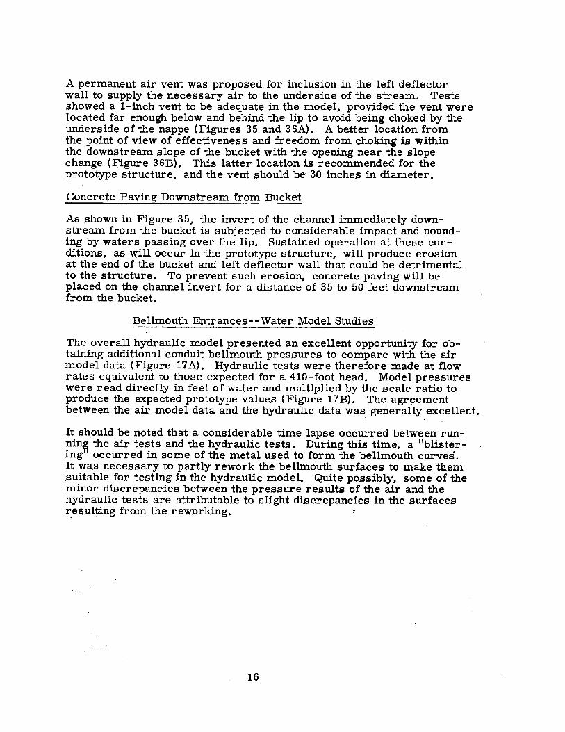
A permanent air vent was proposed for inclusion in the left deflector wall to supply the necessary air to the underside ·of the stream. Tests showed a 1-inch vent to be adequate in the model, provided the vent were located far enough below and behind the lip to avoid being choked by the underside of the nappe (Figures 35 and 36A). A better location from the point of view of effectiveness and freedom from choking is within the downstream slope of the bucket with the· opening near the slope change (Figure 36B). This latter location is recommended for the prototype structure, and the vent should be 30 inches in diameter.
Concrete Paving Downstream from Bucket
As shown in Figure· 35, th.e invert of the channel immediately downstream from the bucket is subjected to considerable impact and pounding by waters passing over the lip. Sustained operation at these conditions, as will occur in the prototype structure, will produce erosion at the end of the bucket and left deflector wall that could be detrimental to the structure. To prevent such erosion, concrete paving will be placed on the channel invert for a distance of 35 to 50 feet downstream from the bucket.
Bellmouth Entrances--Water Model Studies
The overall hydraulic model presented an.excellent opportunity for obtaining additional conduit bellmouth pressures to compare with the air model data (Figure 17A). Hydraulic tests were therefore made at flow rates equivalent to those expected for a 410-foot head. Model pressures were read directly in feet of water and multiplied by the scale ratio to produce the expected prototype value.s (Figure 17B). The agr~ement between the air model data and the hydraulic data was_ generally excellent.
It should be noted that a considerable time lapse occurred between runninft the air tests and the hydraulic tests. During this time, a "blister- · ing occurred in some of the metal used to form the bellmouth curve.a. It was necessary to partly rework the bellmouth surfaces to make them suitable f9r testing in the hydraulic model. Quite possibly, some of the minor discrepancies between the pressure results of the air and the hydraulic tests are attributable to slight discrepancies in the surfaces ~esulting from the reworking.
16
Sam Peng
Sticky Note
None set by Sam Peng
Sam Peng
Sticky Note
MigrationNone set by Sam Peng
Sam Peng
Sticky Note
Unmarked set by Sam Peng
Sam Peng
Sticky Note
None set by Sam Peng
Sam Peng
Sticky Note
MigrationNone set by Sam Peng
Sam Peng
Sticky Note
Unmarked set by Sam Peng

:
REFERENCES
1. "Hydraulic Model Studies of the 7-foot 6-inch by 9-foot 0-inch Palisades Regulating Slide Gate," W. P. Simmons, Jr., Report No. Hyd-387, USBR
2. "Pie-zometer Investigations," Allen, C. M., and L. J. Hooper, Transactions, ASME, Volume 54, 1932, pages 1-16
3. "Field Investigation of Spillways and Outlet Works," Guyton, Benson, Paper No. 532, Journal of the Hydraulics Division, ASCE, February 1958
4. ''Hydraulic Design Criteria, " Sheets 050-1 and -2, Corps of Engineers
5. "Hydraulic Model Studies of Glen Canyon Dam Spillways and Outlet Works," T. J. Rhone, Report No. Hyd-469, USBR
6. "Improved Tunnel Spillway Flip Buckets, " T. J. Rhone and A. J. Peterka, Journal, Hydraulics Division; Proceedings, ASCE, December 1959
17
Sam Peng
Sticky Note
None set by Sam Peng
Sam Peng
Sticky Note
MigrationNone set by Sam Peng
Sam Peng
Sticky Note
Unmarked set by Sam Peng

WASH
C 0 C
10
KEY MAP
.i
w
E
A
L
y
0
FIGURE I REPORT HYD. 468
E
s A N
A N
~-' ·-·-·-·r·
UNITED ,STATES DEPARTMENT OF THE INTERIOR
BUREAU OF RECI-AMATION
COLORADO RIVER STORAGE PROJECT Ml ODLE RIVER ,QIV.--GLEN CANYON UNIT- ARIZ.-UTAH
GI.EN CANYON DAM LOCATION MAP
Sam Peng
Sticky Note
None set by Sam Peng
Sam Peng
Sticky Note
MigrationNone set by Sam Peng
Sam Peng
Sticky Note
Unmarked set by Sam Peng
Sam Peng
Sticky Note
None set by Sam Peng
Sam Peng
Sticky Note
MigrationNone set by Sam Peng
Sam Peng
Sticky Note
Unmarked set by Sam Peng

~I fl
~
~c \:, '~t-,0?l 1/ "'<"
Intersection of£ sp1/fway with axrs of crest-Sta 20+00 N 2,161,414, ___ ~ E 627, 178- /\-,,
+-
" ~--
---- -----ect ion __ - - - - -er -Gotfotfor~rn-- - --
P ~
;ock /-:::- -ck tro~es-:-,/ , penstotructu~/ , / 5
oo'\ , ./ _ sto 1i;5 r- , Ax's2,160!;so ' ,1e~-
N 626, Q(\c\,{01 E ,\ )0' '-. ,
11°1 e? 001\,0~
'i\
E 627,500 C) C)
"'
, do River orrdge - -_co1oro
c01,0RAV
--------7 0
f-lvfR
+--
\
~
\- 0\10(\ I cO" \ \ et__-----~ cir cu' \ \
er I , -1orrt' / ~(\? ,-----------
/
l ~s~ ~,l I
.._-__ ;_,_ -- _5,;1tc11Yard
~t---
l FIGURE 2
REPORT HYO. 468 3- 8 w 57 _RI REVISED ALINENENT OF SPILLWAY APPROACH CHANNELS
'> ~ ~L-- =< --. 7/r--'
,oo 100 2.00 ,oo
SCALE OF FEET
fl 3085 :!:---,::-:-">- ~ UNITED STATES
DEPARTMENT OF THE INTERIOR
8-'REAU OF R£C:_.:1MATl0N
COLORADO RIVER STORAGE PROJECT MIDDLE RIVER DIV.- GLEN CANYON UNIT-ARIZ.- UTAH
GLEN CANYON DAM AND POWER PLANT
-
3
9oo~ _a.;(~------gl ," '".' :::;c: ~-;~- :;:;~:::;;o:>ru~- -C) 7tiJ ~-APPROVEO~SS~ --- ---
PLAN
! at CHECKEDlf,a.__ -I "' \ ~-

,--Service road ' brtdge
----
1
15Spcs@60' \ ' \ I -- ,----1
\ :
I \ I River outlets trash
rack strus~ures-,,-, I I \ \'
' '
~. """"""'' tunnel
Max. WS.~[L!!!}:.l
Crest-Et. 3648---, E/. 3635-'"j y_
Axis of crest ,,-~ Sta. 20 + oo--'
\ \
\
Gate erection plotform-,1
('"l90 Ton gantry crone
-----ic 11'-Penstock trashrac. k I ____ Y
,, structures----+--, -----if Flootwell mtake-
(if Rive'r outlet El 3425 intakes-El, 3374
', ' '-,
,_
,-Plane of centers,_: Axis Sta. !O•OO
--
·Vista canopy
,-Elevator tower -' Jop afdam-EI 3715 ,,
,---Service road : bridge
40',J.c470',-- ,,20 I I ,_, '--~l l
-.. ;-?!o~k ~umb~r 1 ·6_5p_ct 60: (60
I j
/ /
/
/' /
/'
/
-i;'
\ \ )
/
i
'<.original ground surface at axis
:- if Right spillway ~ tunnel
-Gate hoist
Top of dam- El. 3715;>
Gate chamber-
El 33 74----,
--Ut,t,ty gallery
-6"Dia. air vent
_ ---Gate service shaft
-:l\---Access galleries ,f
--Contraction jomt
0
'--96" W outlet pipe
,,--Machine shop
;xl '
,,-El. 3179
Drainage gallery-: ----Adtt to dramage gallery
SECTION THRU RIVER OUTLETS
FIGURE 3 REPORT HYD. 468
(96" Hollow-jet valve
--contraction joints /,,1 :-;---='-
-Top of dam-
'·---Assumed line of excavation at axis
UPSTREAM ELEVATION (DEVELOPED ALONG AXIS)
,,_ ,,-\--Service roods :--:_--~,------
,---5o'Dio. ~; '"""'"
Max. WS. El 3711 ,: \
Nor WS. El 3700-'
Min ws. for power operation- El 3490--f El 3470--,
------Original ground surface
Filling line gallery---"
Pump chamber gallery. ___ ,,--
Foundation gallery---- --
El 3715
Drainage gallery,,:
\ ,,--Contraction ;oint
-15'-o"w penstock
·-aackfill
3700
w zw "' ~ a er Q"' - z" >- a: ~ <( 6 "" >,: 3720
>>-<I) Wo w 1- a ,.J <I) .J 6 f/) WO w" >-a:>- 3700
CL W a:.,_,
~; 0 0 ..... > •:,
a: ,.J a:" 0 W = 3680 WW <I> CL <!)a: a: w <I) w "w a: a: >
3660 a:
3600
3500
3400
3300
3200 ' r,
3640 3100
c·if 112, 500 K. w generator
I I
Reservotr orer-· l !7R--1 .J-l--H u-I ,n,- ~c. '-1--"""T'-_ __.1...-1--
13-r" ,_J,,.., - k- J- "' Reservoir capacity '
~ !/1,,,,
~
J.-,~
V'
I
j/(',.,,,-1
i:::;t-"1 I [_ J.--1 I
7, I
,1- 7 ;
-
-
I 1:'- .-- 4·96"0utiets ,_J.-- ,,,,
'- Present 01/water ,_,_
I ,..U-t-1--1-t !
'- Spillway di~ e I ' 1 -
! -1 , I i
I _j_
10 IO 20 25
RESERVOIR CAPACITY- l,000,000 A.F. RESERVOIR AREA- 10,000 ACRES
SPILLWAY DISCHARGE-10,000C.fS. DISCHARGE FOR T.W. ELEVATION-10,000 C.F.S.
RIVER OUTLETS D1SGHARGE-1,ooo G.F.S.
l !
'
' '
I
30
3180
3170
3160
3150
3140
3130
3120 ••
2-300Tonpowerplontcranes TAILWATER, AREA, CAPACITY, AND DISCHARGE CURVES
,-Gantry crone _ __.,_-,;;;.M:;:.ox, rw E/3/83
,---R,prap NOTE Final foundation may vary widely from assumed
excavation Imes shown.
z 0 .:: " > w
~
ffi >-
" "' ,.J
" >-
~ SECTION THRU PENSTOCK AND POWER PLANT
Sta 26 + II 72------,:,,
S 0 0,0035~
--
:
~~;;;~~;~:~~-~--~4~! 'iDiia~s:e~cit/~On~===============~=:;;Ll~K~:~~::_~~-r\£:'-109. 92' R.
' - -Sta. 35 +22± ~.i-, : \'-, ,_.,,..------; ' -, -Sta 37•77
100 100
SCALE OF FEET
·El 3153.40
SECTION THRU RIGHT SPILLWAY TUNNEL
,oo 300
UNI TED STA TES
DEPARTMENT OF THE INTERIOR BUREAU OF RECLAMATION
COLORADO RIVER STORAGE PROJECT
MIDDLE RIVER DIV. -GLEN CANYON UNIT- ARIZONA-UTAH
GLEN CANYON DAM AND POWER PLANT
EL EVA TION AND SECTIONS
DRAWN _____ E_-~~'-:.· ___ SUBMITTED. _____ CJ_.,.,;t:...~ ________ _
::::::~~:°~~ ::::::::~~;;~ --. ----_ -i! ~~~:oc. c;;;,-;.-,;-~;;,-;EER
557-0-73

=
~ 3800~
0
-COFFEROAM
OOLO.re.4..Do
~
DIVERSION TUNNEL CJ-RIGHT
~ ~
GLEN. CANYON DAM .
... .. ·•.
r~~
--·coFFEROAM
EL .3130.5·-----.
·3200-----
3800 ..,~
GLEN CANYON LEFT DIVERSION TUNNEL
OUTLET WORKS DIVERSION TUNNELS
"' ·'" ",, 0-"' G> -tc "':II
~"' ...... .. ..

/'
~
C,
,,-Top of hoist bridge-EU730.00
~~ .n' co,, n-~'-' '9 /'.c;,,.
:"'°-,: ......... _
(if' "B"Grout hales @ 20't crs., 25'tdeep
~
~~ ···For details of surfacing,
see Dwg. 557-0- I 79
Pipes or drilled hales in tunnel arch far placing mortar or grout by grouting methods. Location as directed.··
Rings of 1{radial grout holes --- --
' _.--Rings of1{radio/ grout '<" holes @ 20~ crs., 20~ deep.
Alternate rings of1f radio/ groutholes--~Li-~~ ';;;I,
PLAN
Pipes or drilled hales 1n tunnel arch for placing mortar or grout by grouting methods. Location as directed, ..
1j Std pipe---._
Alternate rings o~ 1-j"radia/ grout ho/es< \
' :,3"orainage holes · '
-1---offset 2{std. pipe ,: header 24"from ring of
Cap------
'A" Line
(3 "orainage holes
\' 2!9"0ownstream ' of and vaflable
upstream of :· ~ta.23>26.24'
---4"std.pipe '\ Rings of if r~diol grout
\ ho(es @ 20 _ crs., '-. 30± deep~-
-<· ... , , 110 . 1 .. \l'·'I . '.~ .. , l_// 3"dra1nage holes. I~ - . - %;~ -~
HALF SE:CTION UNSUPPORTED
TYPICAL GROUTING DETAILS TYPICAL DRAINAGE DETAILS
'('-'-
TYPICAL GROUTING DETAILS TYPICAL ORA/NAG£ DETAILS SECTION C·C
El. 3182.0/J._
~
~-_..-' ------------~~ ~~~ ..JL, )("°"
OI 81 ~
COLORADO RIVER ·----->-
"'' a:
,--Wrop mpples with paper to prevent bonding with / concrete. After completion of grouting or dolling
/ of drain hales, remove mpples and paper In grout hales fill all nipple recesses with drypack.In drainage holes, except drain outlets in roof,plug coupling and
J'I o;,,~(':'/ n1pp~: recesses with drypack.
, · C.std pipe '---Coupling
DcTAIL Z TYPICAL SURFACE CONNECTION
FOR If, 2f: AND 4"STD. PIPE
; rr __ f
Roof support bal~,: !
~ ~,t·_:f
"/{Line.--
Steel nblDW'------·
•0-0ptiono/ foot beam omitted
·--optional foot beam
HALF SE:CTION STRUCTURAL STEEL RIBS
WITH LINER PLATES
HALF SE:CTION HALF SE:CTION ROOF SUPPORT
BOLTS STRUCTURAL STEEL RIBS
WITH METAL LAGGING
DE:TAIL U
DE:TAIL V
fabric -'-+
DE:TAIL OF CHAIN LINK FABRIC WITH ~------ SECTION B·B
TYPICAL TUNNEL SUPPORTS
I ROOF SUPPORT BOLTS
TYPICAL SUPPORT DETAILS
~ -~
-"" ~ ---f Std. pipe extended into rock, to be ca lked with lead wool or grouted
·--·i;'Std. coupling or swagep1pe end.
--tf''a'' Grout holes,25'.±. deep.
DETAIL Y
_,-"\ ,v,
\::% 'R.
\,®{;~ ',;% %',<,=>%
@,~ :,.li"':,;;.,,--
~-\0.,. ~-'f'% ye\.....,>-<, o-,r__.... %\~ ~'0 :.~,% '~ ~~'~ \, ~ ':°b :-0 '~ ,\\
Sta.23+26.24----,.;
..-r-Lining thickness varies. r_:,
Sta.24+30.30
-- ........ __
-~ "'&
!:)
.,<
SECTION E·E .__:·#// Anchor ba~@) icrs':both ways, B'min. ,/ embedment into sound rock,and / grouted in p/ace.---------------------
SEC Tl ON F-F
f<---Concrete from Sta. 26+1172 ta Sta. 36+52± to be--: placed before diversion of river is begun.
->j
,-Rings af 1f radial grout hales@) 2o't crs., / ___ 40'±deepto extend 200'± upstream.,.
-:------"' -- -- --100':t -- --
·<>, ,--!f'Radial grout holes in tunnel : ___ J ___ a_r~~,!..O} deep i ,Jl.31820D
LINER PLATES ONLY STRUCTURAL STEEL RIBS ONLY
TYPICAL TUNNEL SUPPORTS
1{ Radial grout holes @ 40'± crs.,20'± deep-----
1{ Radial grout holes @
20'± crs., 20'± deep----?'yt~·
"a"L. .,{_· we--- ,·.
" .. "
SECTION D-D or_;::: -400 '± - )=,=,±=I ,c:i~~L/'j/ft, E ~ r: J' Keyed joints in qravity wa/1-.
',(~
-<7F STA. 27+12t TO STA.34-t-30I
t I t --Construction joint e"---Transitldn-- ,,-El.3152.94
~lape:D003~":tw - -~=-~:-=:_ __ t: ,-E/3130 ~
CONCRETE FINISHES Tunnel below f or spring line ____________ J4 or U3 Tunnel below Ii from Sto. 23•20 to Sta. 26+15 ____ .F4 with special
finish ar UJ lntef!or surfaces downstream of Sta 36 • 52z F4 ar U3 All other surfaces ___________________ f2 or U2
NOTES "a' Grout holes to be drilled and grouted after completion of
excavation far intake structure and prior to placement of concrete m mlake struoture. Radial grout hales in tunnel to be drilled and grouted after lining is completed.
Drainage hales to be drilled after all grouting is completed. Chamfer all exposed corners f unless otherwise specified. Reinforcement in spillway tunnel /ming required but not shown.
J-B- 5 7 ~I REV/SEO ALINEMENT OF APPROACH CHANNEL
o,71/'J~ IS UNITED STATES
DEPARTMENT OF THE INTERIOR BUREAU OF RECLA.MAT/ON
COLORADO RIVER STORAGE PROJECT MIDDLE RIVER DIV.- GLEN CANYON UNIT--ARIZONA -UTAH
GLEN CANYON DAM LEFT SPILLWAY
PLAN AND SECTIONS
TYPICAL SECTION THRU TRANSITION Sta. 26 •11.12 -- --~
SECTION A·A
DL>- EL>- , Sta. 36+ 52± - _,; -----10.00'--->l
-<-' F Contraction joints:
.,.: Sta. 39 ,o,.-- ;:::;;, __ " ::~::.::: ·:~:;;;;;:;;;·~·:_-__ _
CHECKEo-'J1l-C. ~,A._...o.PPROVED ___ -{~~G,N_E_ER- - -
DENVER, COLORADO, NOV. 19, /966 557-0-87

Trashrack structure-,,,,
SCALE OF FEET
,,Construction raise to be used Extent of final tunnel plug-, ' for air supply
~---- '(__ : ,Outlet gates; : \ / -~-_e;
?//, -------------~----- ___________ _ __ Ef_~o-:-, :\::_, L_ __ ~-- '---- - ------ ------- .--u 3153±
FIGURE 6 REPORT HYO. 468
E/3170.67-; , _E/3I3137···• --"T __
Sta. 6+85.50····-,, Sta. 22+o3 20-~ >---Sta 23+78.20 ': Sta.
36+
94.oo- ___ ->-1 3133. 58 Sta. 26+11.72---r
El 3156 00- ,- -·
El. 313737-·,:,
ELEVATION ALONG f 41' DIA. CONCRETE LINED DI-VERSION TUNNEL
Gate operating chamber ---
El. 3/88.00-,
-<7A ,-3" Ventilating pipe
,-7'x5' Access adit for : backfilling chamber
er>-
Note.- Remfarcement for gate operating cl>-chamber, 1',5' access add,gates and conduits not shown. Gates to be left ,n place and gate
Ji_ Diversion tunnel.El. 315787 opera/mg chamber, dawns/ ream section of f ___ ______ -~-- _ conduits, r'x 5' access add, and 5x 7 'access adit .7'-o"x/4'-6" Condulf(ste to dam to be backfille,d and grouted before
lined bottom and sides) fmal section of tunne, plug 1s pieced
SECTIONAL ELEVATION THRU OUTLET GATES
20 0 20 40
SCALE Of FEET
SECTION A-A
0 5 10 15 20
SCALE OF FEET
.-Original concrete lining
:,·f Diversion tunnel, El. 315787
-:,
. " '" ::,, ~ ' ..:.~ !'"~,
SECTION C-C
I 0 IC
SCALE OF FEET
El. 3156.00-
15
SECTION 8-B
.-Original concrete • tunnel lining
Diversion tunnel, El. 315787
WIOENED ACCESS ADIT IN TUNNEL PLUG ANO REVISED NOTE
RE:V/SED TO CONFORM TO THE DETAIL DRAWINGS TO DATE.
UNITED STATES DEPARTMENT OF THE INTERIOR
BUREAU OF RECLAMATION COLORADO RIVER STORAGE PROJECT
MIODLE RIVER DIV-GLEN CANYON UNIT-·ARIZONA-UTAH
GLEN CANYON DAM L £FT DIVERSION TUNNEL
OUTLET WORKS
DRAWN J.L TRACED_~_,/~~-~~- - - - - ·.SUBMITTED ___ _Q._;;(;~ CHECKED_<':t/...L ______ RECOMMENDED _7~~ ---, ~,_...l.,.,_APPROVED~ --- ---- - - ----
DENVER, COLORADO, JAN 30, /9~8

·.;, _, T
' '
FLOW>
h~G-u~~d--------B~ o:-~- }1' Service gate hoist
~J;f;.111 - :: ll~-
9'-0~---- --- ----~
.:---~ i ,--- " ~N~ .ff ff • 11\
Ill I
Ill
3t l&J ;;
:c:: q: ..J a.
q: I
q:
:c:: 0 i: u llJ 1/)
@( L
::t:
I
~/:ii:
~
~
FIGURE 7 REPORT-HY-o--:-468
~
~ e: :c:: u,O :.::i::: 3t q: 0 :s QI&.!
..J LA., I&.! ..J
iQ~~I 11--~ 111 ~ I 11/il:r II [] II~ b 11u II ~ru ., I t~i- ~
..J q:
' ' ' ' '
w 0
-- _ ---------12'-Jff----
r---------- -- --------- ------------- ----------------------
,-With hanger stud in ;/ disengaged position
;--:-22,:'!>t<_ - - - - - --- - - -- - - - -----11' 9 :t--' ' ' ' ' :
~
®
(.) I
(.)
3t l&J :::,.
~1
0 0
_J Ill ? L ~ I ~ en ta
~ 'cS~ ~ll\4 i4i
sf 0 0
~
L (.)
~ '='-~ "" " ""
' _} L !J
(.) Q Q
---------------_y
:c:: :c:: Oo ~j:: ~q: 1/)t LA. ..J ..J l&J q: :i:
It: q: ~ ~ iii
~ q: (.!)
l&J (.)
:;;
~ ~ ~~i: '--, ---- '-5:Z:overa/1-------------------------------- 40 16
r ~ ~ --- nl
I
:c:: 3t 0 :i: 1/)
<D
----->t< ----3'-o"----- -j-, ' ' ' ' ' ' ' I I 11
: -: -/
® (.!)l;,
"" "' ~
:g i
~
:c:: 0 j::
~ l&J ..J l&J
..J q: :c:: 0 i: (.) l&J 1/)
l&J 1-q: (.!)
Q It: q: :::, (.!)
?!!:.Al
~ ~ I ~Ll
Q I
Q
3t l&J :::,.
ASSEMBLY-LIST OF DRAWING$ _________________ _ ASSEMBLY- SECTIONS ____________________ _ LIST OF PARTS -MATERIALS ______ ,_ ______ _ UPSTREAM BONNEL ___________ - -- ---- __________ -- - ____ 557- D - 687 DOWNSTREAM BONNET- BONNET COVER---- _____ - - - ________ 557 - D - 688 UPSTREAM BODY ______________ - - --------- -------- ---- .557-D- 689 DOWNSTREAM BODY - GUARD GATE ____ - ------------- ____ 557-D- 690 DOWNSTREAM BODY-SERVICE GATE_ ______________________ 557-D- 691 LEAF ________________________________ ----------------557-D - 692 CYLINDER - PISTON - STEM - NUTS ________________________ _ 557 -D - 693 INDICATOR PARTS-BOTTOM BODY COVER-CYLINDER HEAD .• 557-D-694 SEAL PARTS - DOWEL - STUDS ______ -- ____________ --- ____ 55 7- D - 695 BELLMDUTH LINER ______________ -------- ____ - --- -- ----557 - D - 696 UPSTREAM LINER$ ___________ -- --- --- - - -- - -- --- -----557 - D - 697 DOWNSTREAM LINERS ________________ - ____ - -- - - - --- - .557 - D- 698
DOWNSTREAM CONSTRUCTION JOINT LINER __ --- ----- ---- - _557 - D - 699 GREASE PIPING -LADDER - HANDLING EQUIPMENT ____________ 551-0 -ITTO
REFERENCE DRAWING JNSTA LLATION __________________________________ ----------557-D- 683
P/EZ0METER PIPING- STA. 22+03.20 TD 22+-5/. 70 _____ - - - - -- - ___ 557- D - 1636 PIEZ0METER PIPING-STA. 22•51.70 TD 22+63.20--------------.557-0- 1644
PART ill WAS PART~-
UNITED STATES DEPARTMENT OF THE INTERIOR
BUREAU OF RECLA MAT/ON OOLORADO RIVE:R STORAGE: PRO.JE:CT
MIDDLE: RIVE:R D111.-GLE:N OANYON UNIT--ARIZONA-UTAH
GLEN CANYON DAM LEFT DIVERSION TUNNEL - OUTLET WORKS
7.0' x /0.5' OUTLET GATES ASSEMBLY-LIST OF DRAWING~
:::::~-~~:~E:~::::::::~~~~~~~~~: r-- ~- c~ ...... o .. --ira'"~,~Yi't7i~u"' . -- --- -- ·---DENVER, COLQR.-...,u, ..,e_._,. _,;4, 1:11':JCII
SHEET I OF 17 557 - D - 684

I'------ -- --------- --- --------89.9" ----- -- - -----------------+-! ~ .. 12" -...»+<--------------------72" ---------------------- 59"k.. I I B I • I
' JI
' JI ' JI ' '
11
' 1' ' 11 I II AL+-- d
11 11
I IJ ' 11 ! l!. :..,. .. -Chute---:: : ::
' I ....,il,!!fL_
1 !--Sond botto111------1-.. ~--, I
_ .. I I I I ' !
I I J n I J I •• ----~
.:,1 ·j--T ·- --!:-··
I : ~ WI
I ' i ~,.,JI.O.el ___ .... 4 I I I I
' ' '
-I? ' "" ' l e
"'
a1 +-1 .... I 01 :!:.I -aJ "-'1
-B
PLAN
-----Adopter ring required -----32.e·--:·--- - ' ~2.1" to join pipe to back --------a4.9---- -- _ _, of heodwoll.
SEGn'IONAL ELEVATION A-A
A-SCHEMATIC VIEW-OVERALL MODEL
\ ,-12" Elbow/ I __ ___,,__
I I
/
,--Sheet metal slide gote
SECTION 8-B
DETAIL A DETAIL B
8-INLET DETAILS
j0,93'4: ~, ~-j'
FIGURE 8 RE PORT HYD. 468
,,-Oetoil-C
SECTION C-C HALF SEC. PIPE HALF SEC. TRASHRACK
DETAIL C
TRASHRACK DETAILS
0-TRASHRACK
GLEN CANYON LEFT DIVERSION TUNNEL OUTLET WORKS
MODEL FOR TUNNEL ENTRANCE CALIBRATION 1: 41 SCALE

' I
+
FLOW ____ ,_ ----------t-
+
20 or 22 Ga. Galv. Iron-_,,
(Left) Conduit
(Center) Conduit 2---
(Right) Conauit 3-----
--·See templates for bellmouth shapes
PLAN
r---5.0- ->-:-< ---------60.0 - ~ ' '
T---~ I I I
: r I I I I I I I I I I I
I I • 10 Io 1": ,o IN I : I I I I -+-----1---1 I I I I I I I ' I ' I . ' o, "'I l.0/ <:-', I I : I
I
' i _i_ I
_t ___ ,_ __ -.11
FLOW ____ ,_
595
0.3o'\\0.60')
Velocity traverse stations-,_
' I \+
FLOW ___ ,_ -+-+------- --------
+
!-x• y•
··10 52 + u2= I
.., "' '?
T
I .. I + I + ,
I
+-,.--
i I · ja l i 'T t--+--1__ I I 1· I : ' ! t -+ t '
-1· -- - -- -- - -- - --+- -- + i ~ - --- ---- ·- -,--- l, .. ·-- -----+ • 1·.---~4.68"--1668\T3-:3s"i- - _117361_1_ _______ 1 I .,; -,,_m· - "" ------ ' _j '.
·tt265~) \5.-4-01- - I, I, ~ t' ; _------r-----t-__ _j__ I \ I I _;_ I ! - I _ _;_
ELEVATION
o-- ------- ------ ----
, II Ga.
'
--;.,j~ -----
' '
·14.0-- --- - - ----+--------12.0-----,
' : 3-16 Ga. Sheet metal : slide gates.. ____ _
I
' -----!!---"-
Open Joint in conduits taped closed in tests
' I I I I
' 0
'··Sheet metal bellmouths and conduits
·-------24 Equally spaced ¼ bolts on 22.5 B.C. L!
B
0.30'-
ELEVATION
,,--K + v2 -1 / 72 T:f5'2-
".?
f .. -I i l T1 -i
-i---+---··1-- -------i 8 68- ---i------ --7' ·i ·--+------j-6 68 ----t-- -- ----, +---+---+---+-- -+- ---+---
. .J----!--4 68 +------1 I I ~~~2?r---7 I i i 1:.----t- I I I I \
PLAN
TYPICAL PIEZOMETER SPACING Piezometer openings fi1 diameter
- -T-
5; ~
__ _i_
12" Std. Flange
1 12" Std. Pipe (existing)·--:
TO INLET OF BLOWER >-
Smooth, flush, ~---, burr-free opening ----._d--~ I~-_ 9q_•
j ___ ~:: ,,-Flow surface
·-solder
~ 1.0. Bross tubing-/
TYPICAL PIEZOMETER INSTALLATION
SECTION A -A
Fl GURE 9 REPORT HYO. 468
' ··--conduit '1.'s
SECTION B-B
0
+
<>
•
EXPLANATION
Left conduit, floor, inside corner. Left conduit, outside wall, bottom corner
Right conduit, inside wall '1..
Right conduit, top '1... Right conduit, inside wall, top corner.
Center conduit, top '1.. Center conduit, side '1..
GLEN CANYON LEFT DIVERSION TUNNEL OUTLET WORKS
AIR MODEL FOR CONDUIT BELLMOUTH STUDIES 1•24 SCALE

A - Air model for conduit bellmouth studies
B - Water model for conduit alinement studies
GLEN CANYON LEFT DIVERSION TUNNEL OUTLET WORKS
1 :24 Scale Models For Conduit Bellmouth and Conduit Alinement Studies
Figure 10 Report Hyd 468

FROM LABORATORY, PUMP -----
595
0 0000000
: I
0 0 0 0 0
0 0 0 0 0
FIGURE II REPORT HYO~
---->-DISCHARGE INTO
LABORATORY RESERVOIR
/
Petcock-/
I I I
I II I ---6.00-"'
I (
'',,4" I.D. Rodia tor hose req'd -3 pieces@24" long
:' __ ....... --::-- 0000000
Nate: The three rectangular conduits ore \ , not connected ta the downstream structure): ,, , , ,, ,{_
12"L.W.Piph
~
i
PLAN
" 7e 34.5 -- ------ -- - -- ---- -------------->j
_,.,,---Recommended design I r~-- ~-~-~--;r-==~-------- ~~;] "'=' Initial design--' ',Sloped design ·.;, ~ ~ ~ N ~ ~ (.0 FLOW (.0 l I I --->-- I I
Li __ 1~================d--·Li
,--22 "Diam. tonk 25" long ,,,,/ 11 gage or heavier
FLOW
ELEVATION _J B
GATE -TO -TUNNEL CONDUIT DESIGNS
3-3.5"x5.25" Regulating slide gates 4" long---------
3-3.5"x6.25" Plastic conduits 34.5'' long
f Plastic walls--,,
,--0.93"
,-c- - -- - ---24. 5 ----- - -- ---,+<--------18-00---------:v
3.50'~: f-<l
SECTION B -B
A
i>--
~-1 ,.,.;,,,
'
I ,,,
r---;o~-~ ?_IJ &11222 !::
l-f-J
FLOW:::--
ELEVATION
Recommended design-,,
END VIEW
FLOOR DEFLECTORS -CENTER CONDUIT
,,20.5" Diam. / outlet tunnel
~
" "
/ ,,Plastic top section
>..,o: >o o!«
•\\
\\,, See transition details-'// Na fl onges on downstream plost ic sections·'
"'"' .,o '"' .... .. ..,
1,4"0.o. Seamless tubing
·, ___ Droi n
\ 16 Go. sheet iron----'
'
'··,4"0.o.xo.oa3" Woll seamless steel tubing
ELEVATION
Top of opening in plastic flange--, )
0 60~>; ><- ->, f-c-0 60" ,/ Face off ofter weld,,· : ,, : , · ,/
/3.5\ 5.~511
Rectangular i-c.- 2_00~ \ I r---3. 50--: ! ,,,,,,__,, I conduit : '\ ,~~-- + \ • I I ,, 1. J. \ P1ezometer on top 'E. I : - _L_ --r= _ :
s. of each conduit---------- : ~ ,i it;=:~, 1 ~ : ~-..... " II, I I I • I - I --t-x : "'' : I ,- I I a, I I
' ' @=~ =i
N ~ ~ u "' a, O I 0. I ~ I ' V I I I I I I
---\--11: ' ' I ' I ) 11 I II I II
t-i-=-'--+--~~- _t - 1 l 1: ~-3 [email protected] 1~.J ----,,~ I-<- ---4. oo-- _,....,_ _ -- - - ------ -10.00- -- ------ ------->-k- - ------ --- ----- -10. 50- ·--- - -- ----:-J
Weld al I joints
TRANSITION DETAILS
~------5.?Qu _______ J ci
FLANGES 3 Required -\"mild steel 3 Required - \'plastic for upstream ends
of plastic conduits
o 501~¾- k~2.50 11
L A
t-<-- --
' : ____ _
SECTION A -A
7 ' w ,,/ '·--------------Sheet metal bottom section-.--
GLEN CANYON LEFT DIVERSION TUNNEL OUTLET WORKS
WATER MODEL FOR GATE CONDUIT SHAPE AND ALINEMENT STUDIES
J:24 SCALE

q
"" >, 11100111 !I -~ Ill · -"~ '< )\
"' "' .i~
_L __ _
·o ~
rr----n
f ~-1 1-8~--~80~~- -~ ~2-~.---.,~--f "·Galvanized iron : : : · ; o.s"->,r<'- · N i bottom section
-- ~ I
~ -- --3'-oM -------~ --- -- - - - -- -- 6- 1011
- - - --- --/-·- --- - --*- -2'-4''.. _ - -~- --21
-10.511
- - - --¥- - 21-r- --">;<'-- --- - - -----,f-- -441
- d' ------
PLAN VIEW
~ ·5
~
, Standard 12' steel pipe
,/ __ .-16 Gage block iron\-··- ••
.. ,, s m
8 "' .e A 0 g,
1 r>- ~ +-., -~ If" ~
(/)
"' ~ "' ., .,, ~
"' "' ,,; B K . "' -<7 ,,; I
"' => 'i5 0 C:
"' "' 0
Sheet metal-lined toil box- - ----------
Open channel semi-circular conduit to here (Station 36+96)·---.
,-Sheet metal section
/ :,-Plastic top section 1e' long I ',,
IL~ ~ Elev. 3157.8~\
+- n:or Flow ~ . ·r·· ., ~ ~.< ... ~ll"t ...... / --=;-_:""'" "'~"' ·--t-·~ - J O ::'.:;,.,, "'';t,;.i '':~i,i,';- ,.,, ,,. ''""' ~ Ill * Ill Ill ~> rent plastic co u, , T,m~ _.,J
•••
SECTION A-A (Enlarged)
L>A
ELEVATION VIEW
B Galvanized iron
bottom section··
' . : •,;., -ffi
r<·35~~ Jtt~3.5~~ wr-3.5"~----~ . . - -N
<O . ' __ __i_
C.,.--6 25'.- -- -6 25'--' . .
SECTION B-8 ( Enlarged)
~1 s. o~->;<-- --- -35.o~-- --~
' ' ' '
Excavated channel Invert elevation 3131.0-- -;:
' / ,,_·I03°R.
3140
' ' n I II I II I
l::::-':-=---
. ' 0
·,!., '
'··El. 32 75
C -<7
11 I H 16.5-->f"-- - ----- -50.0- - - - -----"'<
' ' t \ ,, '
1
ti ---------1· --------r : I
JLLEl3157.0:
'"J-,
"' I'-' · - ': ,_-- ·~ Conduit
:: ,, ' ,, ~- - --3 3. 75~ - -- ->ii<- -1.25"
-<J C
r<- ---- --- -- ---s~ s r------- --- -~
~ Conduit
I
:--------41-0"-- ----~
SECTION C-C
3/50
PLAN
3131
;c··-~ Conduit
3,zo
,-, ..:I"
FIGURE 12 REPORT HYO. 468
-------~--
'
11111111 --+ . ' 0
'
,-~ ,,Floor ot El. 3120----~--:,-"
/
------ L
---r
-10'-o'-- - - -- - - - - - - -- -- -- -- --- -->i
' . ----- ---- :------~--~ c---------------7-0-------- ----- -'! ____ ~_ ! .:
2" x 12' Tailgate-- ••.
2" X 4'. .•. I II'
t<-12-->l
GLEN CANYON
' ' : .. ~ IC!-~
0 ' ·' ' ~ : ' '
_____ L_t.i
LEFT DIVERSION TUNNEL OUTLET WORKS OVERALL HYDRAULIC MODEL
1:24 SCALE
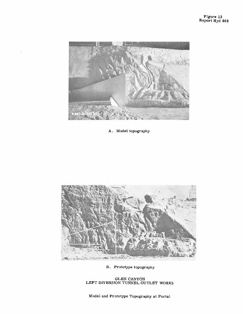
A. Model topography
B. Prototype topography
GLEN CANYON LEFT DNERSION TUNNEL OUTLET WORKS
Model and Prototype Topography at Portal
Figure 13 Report Hyd 468

£1,3258.42-\
_,,-Grovel, graded from ,ftv tf
I " '' '' ' \
\ ~er -r -~---m1J; ",/·t \ ,v~b ''d ,'?: ~. " ! · . '/ 1: '(Wo1i'l<k"'
'
9 ... Q)
ii
!? ~ @,
~ ~ .... i
Sta. ~ + 59.07,/
:
:o ·''\
:/'n,\~,!!
SECTION A-A
-Slope
DETAIL Z
__ -Construct,on joint, top of mit,o/ tunnel portal, ,- - -El. 3227.67-- - ___ ,,-
portal
-Construction joint
__ f 41°0" Dia. diversion tunnel. See Dwg 557-0-531.
---70
--•--Sta. 6+ 95,00
Grovel, graded f ..l.'.' , .. ram 16 to 12 _\
->i f<- 9" Roof bl~ckout-\ •I - I
r--~-2!6" 7 ,, ,,,,-Symmetrical about € ,,!;,,:\!, r M~:"'
y y /
3'6f 1<- /" =o -,;,
' ' ,5'1 I 311
---12'7 a-----*-- 8'109---
7Fit- -T
/ 0
_,JF~-.\ l / l's ;3'' Dia. weep holes _____ _
·t··"-Rib blackouts
, (ii) JO ± crs. each way-~.: · '"':
---------------- ------1l---- -~-0
-- ---- ----30'0~
1/'. ',.~'-Radius varies
from 3c5" Iv 6" ..:, ~
!
0
-- --30'0~--
~'-~:-Protect rib blockou~'s with : / ;,---6"R\ wood fillers sec rely , / __ .a:''
,- _,,, fastened ,n place during : __ ..:-----
-- -- aperat,on as ,nit al , ___ -
;\ tunnel portal-- -------: _
l , ,, ---- - _,,L_ ___ -1/!¾'r-""I
T 3 D,a weep holes @
1
10' ± crs
0 o·:1 ,'0·
HALF SECTION B-B HALF SECTION B-B SHOWING BLOCKOUTS
·~:·'I 6": -~ .<::.·. ·;:,·.· ··C:::, iti
' '..~I
,--
"' ":'
i. £1.316711---,.,,_
SECT/ON G-G
~1A ,--Sta. 6 + 95_00
,-Construction joint
:-----------=-t-~----t----------
lnit,al portal----.,
FIGURE 14 REPORT HYO. 468
---\ "' ,Reference f /,/ \ plane \ \ / /,,
\ \ \ \ ','f-. ',, I
) ' ,;'/,
\ <-,- ,' \ ,I:,~-
\ <:>~//// ,A 0>~--.,,.,,..,.,....~~ ,,,,,,-- --::,,..~ ',r,, ,,,,, 6' / ?"....-, /
,,.-'\ ,~ / ~ / 50 I
,,--,,,,,,-- \ ,,..,,....~:\_,..,.. ;r ,,_~o-,, ,/"~ (:i ,i lk-,e4•~l~
~~\-/ /! I ''°(I I .,,, / I I l'
\ _,,,,..,,, / I , I I
X,,...,,, ~, /,, / I I
,,,,,-,- ' ,,"'J~ I I
./ ', ,Cl,c..: / /
'-, // 11....., ;1
,, "- / I ::,-.... I
,,0; ""-,// / / /
/' I ;,· ' I r, . . ,' , 1 ~ 1 "- D1vers,on
/ ',.j l,i,; / tunnel-,,
/ 'ft/ / , r-
1'- I /
HALF SECTION C-C
I
,------Initial par/a/----- -- --'F,
Assumed rock line. /,--- 3" Dia. weep holes___ · · ',j : ....
Contraction joint location to be determined ,n the field---- \-~-----------------·
rfs 3'.'.Dio. weep holes ~
@IO+ crs. each way- - - -'j::,- ,,..
-"'-(;El.3170_6 7,o:>._-r ----5',t---
I
\ ,,----., '
---t---- \ "..._..._ ..................... 7 //',,,, -~--</:6,:_
_ \_5 Spa\ces @30°=!~~':,, '··----------.,
's,,,
~:',,,,
:'i Troshrack structure\ ',,
' I Symmetnca/ about If ', upstream from reference plane J
,-P.C. Sta. 6+86. 70
, __ Sta. 6 + 85. 50
CONCRETE REQUIREMENTS
FINISHES: All ~urfoces ________________________________ J2 oru2
STRENGTH:
Concrete design based an a compressive strength of not
less than 3000 lbs. per sq. in. at 28 days
NOTES
Chamfer ¾" or toa/ oil exposed corners unless otherwise
specified.
Reinforcement required but not shown. Ribs and columns nat ta be placed with initial tunnel
portal_
~ ;'-, '-L.5•00'
,--'l Troshrock structure I Symmetrical about If upstream from reference plane J.
REVISED TRASHRACK STRUCTURE BASE
ADDED CONSTRUCTION JOINTS AND NOTES SHOWING PARTS OF
STRUCTURE TD BE PLACED AS INITIAL TUNNEL PORTAL i ;· I:
+-----7--+/ ,,
~ r---
f Diversion tunnel
REVISED ELEVATIDNSDN SECTIONS A-A,B-B,E-EANO
DETAIL Z. ADDED STATIONS ON SECTION A-A.
REVISED AND REDRAWN. CHANGED LOCATION AND MADE
REFERENCE PLANE VERTICAL,
UNITED STATES
DEPARTMENT OF 'THE INTERIOR
BUREAU OF RECLAMATION
COLORADO RIVER STORAGE PROJECT
MIDDLE RIVER DIV. ·GLEN CANYON UNIT - ARIZONA-UTAH
DETAIL Y
GLEN CANYON DAM LEFT DIVERSION TUNNEL TRASHRACK STRUCTURE
SECTION F-F :::::~:£~:~.~:;~~- =~==~:::N:~~ -~~Q:~-~~~_::~ ----- ------HALF SECTION E-E
CMEC,<ED P.e.o.- M. F. _ A PPROVE°cH,EF- DESIG~;~~ K::;,~~ER ______ _
OENVER,COLDFfADO, FES. 17) /9!58 5 57-D-610

= 3641
,so,
355,
352
... : 3481 .. I
z 0
~ 3441 .. > ... ..J ... ~ 3401 .. ... n: ::, II)
)
)
)
)
'
'
' n: 33601 ... ~ 3 n: 0 3321 > n: ... ., ... n:
3281
3241
3201
'
'
'
~ ~ 3210
~ V o Entrance slightly rounded ,without trash rack frame ~ ...
~ <> Entrance slightly rounded, with trash rack frame ... + Square -cornered entrance.without troshrack frame ~.& ~ ... • Square -cornered entrance,with trashrack frame ..
I z 3202
~ ~ !:! ... .. >
~ " Free Flaw Into Circular Tunnel ...
..J
,£, ... (Critical velocity and depth occurring just inside tunnel portal) ~ 3194
~ V .. ... n: ::, .,
/ 16,000 20,000 24,000
n: ... !c 3186
/ 3 / n: 0 V ->
1" n: ... / .,
: 3178
I / I ,-Invert of Tunnel Entrance @ 3171.25 /
• - _,L I I I I V 31700 4,ooo a.ooo 12,000 / DISCHARGE -C.F.S. vv /
V .... _,,,/' Tunnel flaw without plug and conduits, _
with rounded entrance and troshrack:·· J --.....
----- .-----,;:,_,.-Invert af Tunnel Entrance @ 3171.25
/ /v V
/ /
·--Flow with tunnel plug outlet works in place -three gate full open
Gate It. elevations -3156.00
I ,-' -Reservoir water level with t" inlet crown
I I
I I
: I
316~0 4,000 8,000 12,000 16,000 20.000 24,000 28,000 32,000
DISCHARGE -C.F.S.
GLEN CANYON LEFT DIVERSION TUNNEL OUTLET WORKS
DISCHARGE CURVES DATA FROM 1:41 SCALE MODEL AND COMPUTATIONS
13640
' ,600
,560
' ,520
, ,480
3440
,400
' 360
' 320
, ,280
,240
, ,200
, 160 36,000
., 'll'TI o., G) -tc :,:::0 ~: :o

A. Res. Elev. 3190 Q = 6,000
B. Res. Elev. 3199 Q = 12,500
C. Res. Elev. 3212 Q = 24,000
D. Res. Elev. 3222 Q = 34,900
Portal Invert Elev. 3171. 25
GLEN CANYON LEFT DIVERSION TUNNEL OUTLET WORKS
Flow Into Diversion Tunnel Portal -Rounded Entrance
1:41 Model
Figure 16 Report Hyd 468

,.,
300 ..i.----,----,---,----,
0:
~250 .. 3: u. 0
~200~"-:-\~-+----r-----1 w u. I
!/) 0:
~ 1501--v~rt----r---- I w ::; 0 N w
~ 100 l--~~\l-----t----1 I .. w 0:
~ I' '> l,,.< I w 50 I \ti 0: 0..
5 10 15 20 DISTANCE FROM ENTRANCE-FEET
SIDE CONDUITS
300 .-----.---------...----........
a:
~250 1-.----+----f-------t---, ; u. 0 1- \ ::: 200 l-----\---+----t----,---7 u. I
!/)
0: w \ ~ 1501--.:::::~1--+----t----,---, ::; 0 N w
a: \ 'I I I ~ 100 I 4 , .. w 0: ::, !/)
~ 501-----i\-___:-,___f-------t---, 0: 0..
0 ._ ___ ._ ___ ._ _______ __,
0 5 10 15 20
DISTANCE FROM ENTRANCE-FEET
CENTER CONDUIT
ALL GATES OPEN Q=32,700
300 .+----,---,---T---,
0: w I-; 250 t""~-----,L----l----l-----_J
u. 0
l-
~200 rw--t----+-----+---_J I
!/)
0: w lwl50 ::; 0 N w 0..
,_ 100 I ~ 111, I I I .. , "' . . I w 0: ::, !/)
~ 5c, I ,ti..1,--:;'.'~~::----il::o.---c::---t----_J ~' ~ "- I
0 .._ ___ ....._ _________ ...._ ___ __,
0 5 10 15 20 DI STAN CE FROM ENTRANCE- FEET
SIDE CONDUITS
0: w I..
300
3:2 50
u. 0
1-w ~200
I !/)
a: w 1-w ::, 150
0 N w 0..
~ 100
w 0: ::, !/) !/)
W 50 0: 0..
0
\
\
__.
0 5 10 15 20
DISTANCE FROM ENTRANCE- FEET
CEN.TER CONDUIT
ALL GATES OPEN Q= 32,700
~0 ...... ----.-----,------,-------,
0: w I- 250 .. 3: u. 0
~ 200 ~~t--+----t---7-w u. I
!/)
0: w 1-w 150 ::; 0 N w a:
~ 100 ~--+~rl-----t--- I:
w 0: ::, !/)
~ 50 ~--~~~:;:::~-,--=-_ 1 _ _,.~: 0..
5 10 15 20 DISTANCE FROM ENTRANCE- FEET
SIDE CONDUIT
~0-----.----------,-----........
0:
~250 .. 3:
~ I \ / With right hand conduit open I :;; 200 . \ / I I I . w u. I
!/)
a: w 1-w ::; 0 N w i.
left hand conduit open.
~ 100 l----.+.41------t-----+----.. w 0: ::, !/) !/)
w 50 0: 0..
0 L... __ ....J. __ _;..,._-==!::::..i..... __ __J
0 5 10 15 20 DISTANCE FROM ENTRANCE-FEET
CENTER CONDUIT
CENTER AND ONE SIDE GATE OPEN Q= 22,000
300 r+----.-----,-----r------,
a: w i250 r\--t----+-----+----1 u. 0
g200 ~rr-t----+----J ____ J
I !/) a: w i 150 r,1rtt----+-----+----- I 0 N w 0..
~100 r--ttt----+-----+---_J w 0: ::, !/) !/)
~ 50 I \ ~°'-= ·,-, ::J>-t-o.. --= ~ I I
O'----'---------------___, 0 5 10 15 20
DISTANCE FROM ENTRANCE-FEET
SIDE CONDUIT
A. AIR MODEL STUDIES
300 ,-----.-----,------,------,
0:
~250 ; ,-,-+---I-- J ~With right hond conduit open.
;20010,_v I w
\ u. I
!/)
0: ~ l~:-With left hond conduit open. I wl50 ~~ I I I
::; 0 N '!! 0..
~ 1001----.'<+----t-----+-----I .. w 0: ::, !/) !/)
~ 50 I------Hl~---t-----+-----
0..
0 .__ ___ .._ ___ _._ ___ ...._ ___ __,
0 5 10 15 20 DISTANCE FROM ENTRANCE- FEET
CENTER CONDUIT
CENTER AND ONE SIDE GATE OPEN Q= 22,000
300 .... -----,..-------------
0:
~250 .. 3: u. 0
:;;200~ ~ 7---t------+--- l I
!/) 0: w 1-w ::; 0 N w 0..
~ 100 r-ti~\t-----l----J __ _ w 0: ::, !/) !/) ~ 50 r----'\\t--.::~~4-;::-----IL~-- I 0.. ,
5 IO 15 20 DISTANCE FROM ENTRANCE- FEET
SIDE CONDUITS
BOTH SIDE GATES OPEN Q= 22,000
300 n---...... ----..... ----,.-----,
0: w250 I-.. 3: u. 0
,-200 w w u. I
!/)
0: w r 150 w ::; 0 N w a: : ,oo ,-r,~----+---~L---1 0: ::, !/)
~ 50 I ~n __ 0.. ,~<c-"-~<~=r--~-- ~11----·· I
0 L...---J.....----'----..1.---__J 0 5 10 15 20
DISTANCE FROM ENTRANCE- FEET
SIDE CONDUITS
BOTH SIDE GATES OPEN Q = 22,000
EXPLANATION B. HYDRAULIC MODEL STUDIES
o = Left conduit, floor, inside corner.
o = Left conduit, outside wall, bottom corner.
• = Right conduit, inside wall ~-
+ = Right conduit, top ~.
¢ = Right conduit, inside wall, top corner.
• = Center conduit, top•~
• = Center conduit, side~ Dato expressed in prototype dimensions for H = 410 feet.
300 ·, 0: I \ w 1- 250 .. 3: u. 0
I-W 200 w u. I
!/) 0: w I-w 150 ::; 0 N w 0..
~ 100
w 0: ::, !/) !/)
w 50 0: 0..
0 0 5 10 15 20
DISTANCE FROM ENTRANCE- FEET
SIDE CONDUIT
ONE SI DE GATE 0 PEN Q= 11,050
300 r'T---...... ----..------.---........
0: I W250 I.. 3: u. 0
t;; 200 N~t----t-----+----1----_J w u. I
!/)
0:
~ I 50 I T'l='I\ I I I I ::; 0 N w a: ,_100 .. w a: ::, !/) !/)
~ 50 I \ ~= .. ....,., .J: ::::n " L-- .:Cl----1 0..
0 .__ ___ .._ ___ ..._ ___ ..... __ __.
0 5 10 15 20 DISTANCE FROM ENTRANCE- FEET
SIDE CONDUIT
ONE SIDE GATE OPEN Q=ll,050
300
0: w 1---250 .. 3: u. 0
lw200 w u. I
!/)
0: w 1-w 150 ::; 0 N w a: ~ 100
w 0: ::, !/) !/)
~ 50 0..
0
11-.
FIGURE 17 REPORT HYO. 468
\ \1
\ \
... "-- ~ ~--._ _______
L-----
0 5 10 15 20
DISTANCE FROM ENTRANCE-FEET
CENTER CONDUIT
CENTER GATE OPEN Q= 11,050
300 .----...... ----.----...... ----
a: w I- 250 .. 3: u. 0
1-w 200 w u.
I !/) 0: w ~ 150 ::; 0 N w a: ~ 100
w 0: ::, !/) !/)
w 0: 50 0..
0 ....., ___ ._ ___ ._ _______ ___.
0 5 10 15 20 DISTANCE FROM ENTRANCE-FEET
CENTER CONDUIT
CENTER GATE OPEN
Q= 11,050
GLEN CANYON LEFT DIVERSION TUNNEL OUTLET WORKS
PRESSURES ON RECTANGULAR BELLMOUTH INLETS
1:24 SCALE AIR AND HYDRAULIC MODELS

0.8
0,4
""I· <I"'
-0.2 0
0.8
I
0 . '" "'I • 0,4
<I"'
0
-0.2
0.8
0.4
0
,.
0,4
lo
.:A
0,4
0.8
0,8
CENTER CONDUIT
I
1,2 1,6
SIDE CONDUITS
A I
0
1,2 1.6
DISTANCE FROM INLET CONDUIT DIAMETER
A. ALL GATES OPEN
+
2,0 2,4
~
2,0 2,4
0.8
0.4
"I. <I"
0
·0.2
0,8
-=1 • 0.4 <I""
·0.2
0,8
0
,_
•
0
u
0
• "
0.4
I~ +
0
1.::.
0,4
CENTER CONDUIT
~
0.8 1.2 , .. SIDE CONDUITS
' • • 0 ' 111. u
o.e 1,2 1,6
DISTANCE FROM INLET CONDUIT DIAMETER
2,0
. 2,0
B. CENTER AND ONE SIDE GATE OPEN
I·
HGtlRE 18 REPOllT HYD. 468
2,4
• 2,4
""I • <I"' II + "I • 0.4
<I" .
0 +
0
.. 0.2
0,8
011
"'I· <I"'
•0,2
...
V
0 0,4
1•
. b. •
0.8
• ~ i ,
1,2 1,6
DISTANCE FROM INLET CONDUIT DIAMETER
~
2,0
0. BOTH .SIDE GATES OPEN
I
-0.2 2.4 0
1,2
1,1
(> 0
ii
0.4
' ~ lli
0.8 1.2 1,6
DISTANCE FROM INLET
CONDUIT DIAMETER
2.0
0. ONE SIDE GATE OPEN, ONLY
0 0
" 0 A . o<. GI ,. . .. -
2,4
• • . . . lo . 0 0 . 9 0 •
•
0 0,4 o.e
-• •
1,2 1,6
DISTANCE FROM INLET CONDUIT DIAMETER
lo • 2.0 2.4
0
0,8
0,7 0 ,10 ,20 .so i!-0 .60 .60
DISTANCE FROM WALL CONDUIT DIAMETER
.10 ,BO J>O
E. CENTER GATE OPEN ONLY F. VELOCITY DISTRIBUTION IN TUNNEL 0.75 Diameter Upstream from Bellmouths
NOTES
Pressure Factor "' ~/
6h • Piezometer pressure referred to 'l, minus conduit pressures ot downslreom end of bellmoulh.
hv = Velocity head in conduit at downstream end of bellmouth.
ond D a Width of stroighl conduit for sidewoll piezometers. a Height of conduit for floor ond ceiling piezometers.
GLEN CANYON
Al I Gotes Open
EXPLANATION
o .. Left conduit, floor, inside corner. o = Left conduit, outside wall, bottom corner. A a Righi conduit, inside WOii '!.. , = Righi conduit, top 4.. o a Righi conduit, inside won, top corner. • ... Center conduit, top t • "'" Center conduit, side q_
LEFT DIVERSION TUNNEL OUTLET WORKS PRESSURE FACTORS FOR RECTANGULAR BELLMOUTH .INLETS
DATA FROM P24 SCALE AIR MODEL
.
1,0
\

tifrilJ·.'~
. ' .
.
,,·Cut 3'extra strong pipe to fit slope of / bellmauth and weld into place, centered : between ribs as shown, ofter liners
·:_. ; ore placed and a/ined. (See Section ·-·----r--- ---- ------- --- ---
. 0. ·d 0
·:.O ,e; C> ·"
E-E
/
'·upstream body-'
, ,. SECTION F-F ·-J-14 NPT. Grout connection
I See Construction Specification for detailed grouting instructions J r-< ----7~8"---->-t
~ Weld B! to fill, ~ to fil, and §g to M r 11 'ofter grouting controct1an joint at ! G _ Sto.22+1a.20.(See Specif1cotionsl
SECTION
REFERENCE
G·G
DRAWINGS 7. 0
1
x 10.5' OUTLET GATES ASSEMBLY-LIST OF DRAWING$ ___________ 557-D-684
CONTROL INSTALLATION· LIST OF ORAW!NG$ ______ 557-D-/469
~
Ce,sfro<f,~. ;_~n. f ;
~ ~-~ V ~\ 1· /- 2"Min ° [I ~, : D <:~,of: ',1sbestos sheet pocking, \ .. "), < 145
· " ·:. <·.- ... ·· · !±£ on sides and bottom
\, -, • .;, SECTION K-K of expansion joint.
ANCHOR BARS FOR GATE AND CONDUIT
AL/NEMENT BOLTS--PIEZOMETER PIPING
STA.22+03.20 TO 22+5t.70
PIEZOMETER PIPING
.557- D-1 D20
_____ 557- D-1636
'· ·"\,m.1.-.1
L
STA. 22+ 51. 70 TO 22+63. 20. __ .557· o- 1644
EXCLUDED EQUIPMENT The manufacturer will not ,,e required to furnish equipment which is not co(led
for on the fist of parts and materials, Owg. 557·0-686oron the details.
INSTALLATION NOTES
FIGURE 19 REPORT HYD. 468
not shown)
The guard gates. service gates, and liners wi(f hove been match marked in pairs by
the shop. After the gates and liners ore assembled, all joints in the ffuidway shall be flush. Any offsets shall be faired to adjacent surfaces at a slope of I, 20.
,-Position
·6·.. ·-~·
D
SECTION B-8
/ indicator 22
The concrete shofl be carefully placed during embedment of the gotes ond liners to ovoid distortion. During concrete placement the olinement of the gote seo(s
shall be checked ond the gates readjusted tf necessary to compensate for any shifting which has occurred. I See Construction Specification far
ed concrete p(ocement 1·nstructions.)
6 - 2:., ~9
o.
,. c-/32
GREASE PIPE TESTING After installing grease piping but
before concreting, plug grease outlets in seal seats and apply grease at 500 ps.i at inlets.
Caution: Remove plugs ofter testing.
PIEZOMETER PIPING
Piezometer piping installed in outlet conduit No. 2 only
PART~ WAS~ IN SECTION B·B. I" VENT HOLES AOOEO
TO PART~ !...!!______§__CT/ON F-F.
{;,;~~~~-il~4',~~~+;1c<~'.F~Jd·-j .. SECTION A-A
UNITED STATES DEPARTMENT OF THE INTERIOR
BUREAU OF RECLAMATION
COLORADO RIVER STORAGE PROJECT
MIDDLE RIVER DIV.- GLEN CANYON UNIT--ARIZONA- UTAH
G L £ N CANYON DAM LEFT DIVERSION TUNNEL - OUTLET WORKS
7.0' x 10.5' OUTLET GATES INSTALLATION
::::::~j£~~:::::::;.:~:ffi~/_:_~-~~ OEN VER, COLORADO, DEC. 24,1958
SHEET" I OF / 557-D-683

3 Gates full open, Q = 17,250
3 Gates 50% open, Q = 6. 880
3 Gates full open Q = 32,300 cfs
3 Gates 50% open, Q = 12,860
A - 100-Foot Head
B - 350-Foot Head
GLEN CANYON
Figure 20 Reoort Hyd 468
3 Gates 75% open, Q = 10,880
3 Gates 25% open, Q = 3,440
3 Gates 7 5% open, Q = 20, 340
Gates 25% open, Q = 4,870
LEFT DIVERSION TUNNEL OUTLET WORKS
Tunnel Flow Conditions With Parallel Conduits - Three gates open equally 1:24 Model

Figure 21 Report Hyd 468
L & R Gates full open, Q = 11,510
L & R Gates 50% open, Q = 4,590
L & R Gates 50% open, Q = 8,580
L & R Gates 75% open, Q = 7,250
L & R Gates 25% open, Q = 2, 300
A - 100 Foot Head
L & R Gates 75% open, Q = 13,570
L & R Gates 25% open, Q = 4, 300
B - 350 Foot Head
GLEN CANYON LEFT DIVERSION TUNNEL OUTLET WORKS
Tunnel Flow Conditions With Parallel Conduits - Left and Right Gates Open Equally. Center Gate Closed
1:24 Model
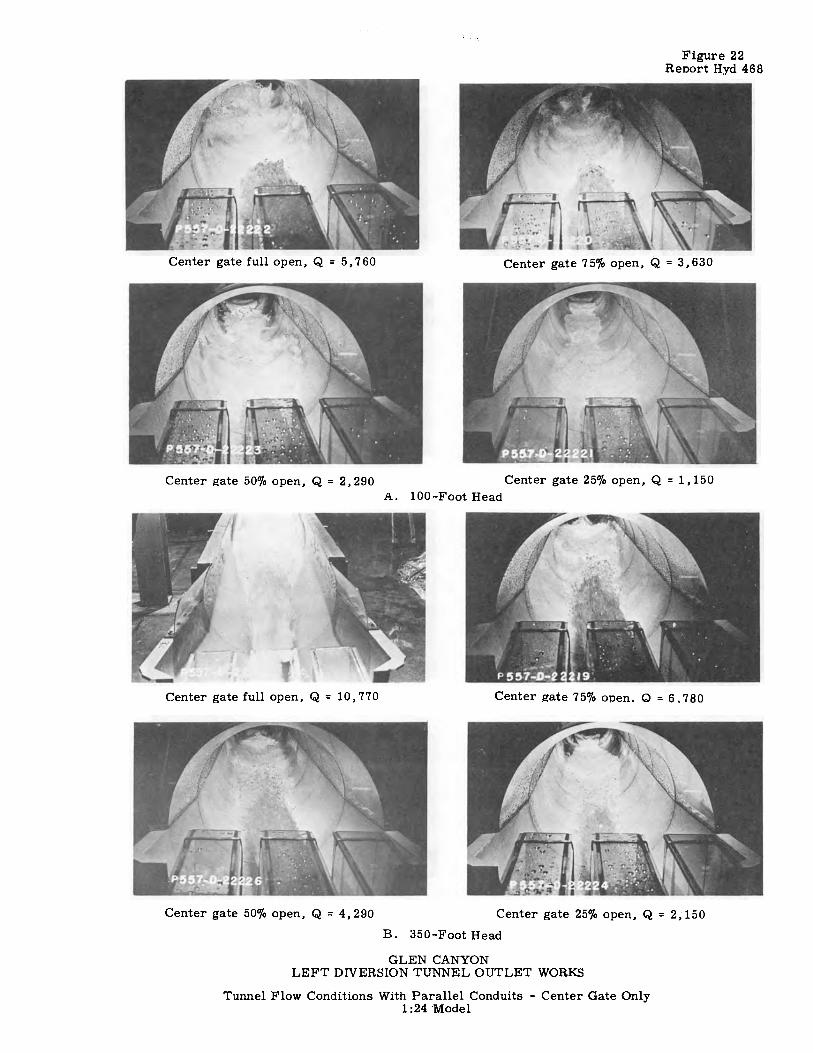
Figure 22 Report Hyd 468
Center gate full open, Q = 5,760 Center gate 75o/o open, Q = 3,630
Center JZate 50% open, Q = 2,290 Center gate 25% open, Q = 1,150 A. 100-Foot Head
Center gate full open, Q = 10,770 Center jlate 75% open. Q = 6. 780
Center gate 50% open, Q = 4,290 Center gate 25% open, Q = 2; 150
B. 350-Foot Head
GLEN CANYON LEFT DIVERSION TUNNEL OUTLET WORKS
Tunnel Flow Conditions With Parallel Conduits - Center Gate Only 1:24 'Model

Figure 23 Report Hyd 468
L & C Gates full open, Q = 11,510
L & C Gates 50% open, Q = 4,590
L & C Gates Full open, Q = 21, 500
L & C Gates 50% open, Q = 8,580
A - l 0Q_Foot Head
B - 350 Foot Head
GLEN CANYON
L & C Gates 75% open, Q = 7, 250
L & C Gates 25% open, Q = 2,300
L & C Gates 75% open, Q = 13,570
L & C Gates 25% open, Q = 4,300
LEFT DIVERSION TUNNEL OUTLET WORKS
Tunnel Flow Conditions With Parallel Conduits - Left and Center Gate Open Equally. Right Gate Closed.
1:24 Model

Left gate full open, Q = 5,·760
Left a-ate 50% open, Q = 2,290 A. 100 Foot Head
Left gate full open, Q = 10,770
Left gate 50% open, Q = 4,290
B. 350 Foot Head
GLEN CANYON
Figure 24 Report Hyd 468
Left gate 75% open, Q = 3,630
Left gate 25% open, Q = 1, 150
Left gate 75% open, Q = 6,780
Left gate 25% open, Q = 2,150
LEFT DIVERSION TUNNEL OUTLET WORKS
Tunnel Flow Conditions With Parallel Conduits - Left Gate Only 1:24 Model
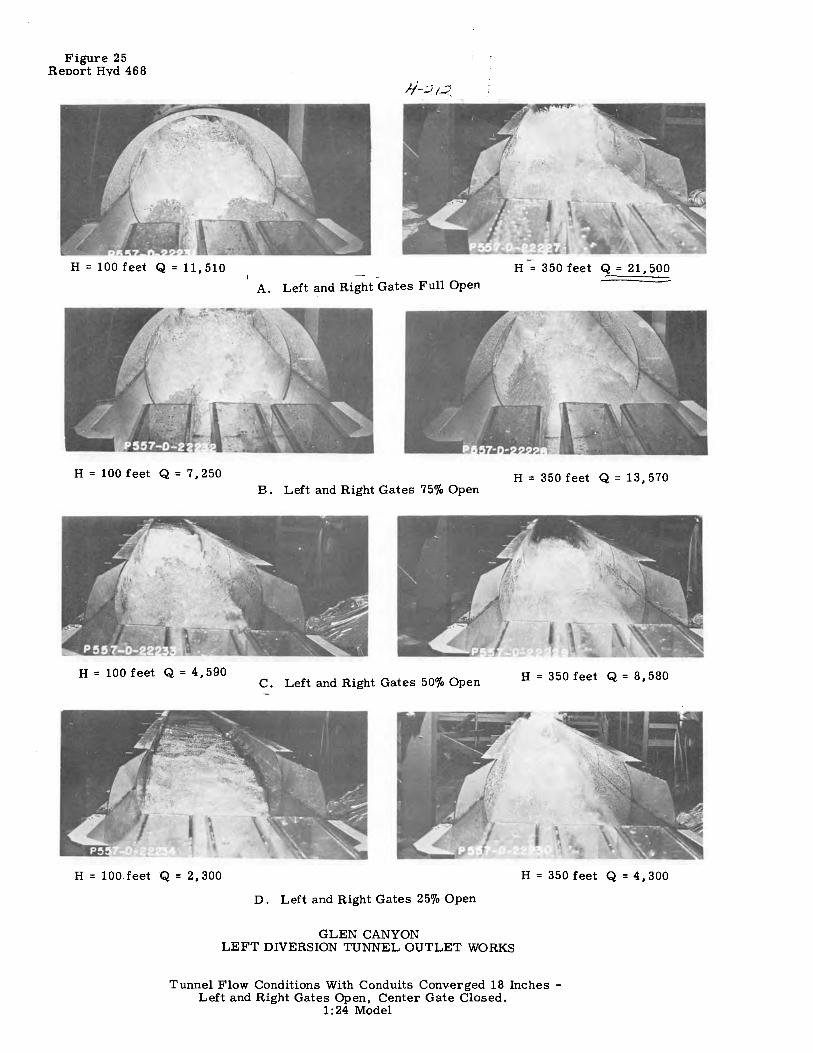
Figure 25 Reoort Hvd 468
H = 100 feet Q = 11,510
H=l00feet Q=7,250
H = 100 feet Q = 4,590
H = 100 feet Q = 2,300
H = 350 feet Q = 21,500
A. Left and Right Gates Full Open
H = 350 feet Q = 13,570 B. Left and Right Gates 75% Open
C. Left and Right Gates 50% Open H = 350 feet Q = 8,580
H = 350 feet Q = 4,300
D. Left and Right Gates 25% Open
GLEN CANYON LEFT DIVERSION TUNNEL OUTLET WORKS
Tunnel Flow Conditions With Conduits Converged 18 Inches -Left and Right Gates Open, Center Gate Closed.
1:24 Model

12..:foch deflector 6-Inch deflector A. 100 Foet Head - 3 Gates Full Open, Q = 17,250
Figure 26 Report Hyd 468
12-Inch deflector 6-Inch deflect9r1nch deflector B. 100 Foot Head - 3 Gates 75% Open, Q = 10, 880
12-lnch deflector 6-Inch deflector
C. 350 Foot Head - 3 Gates Full Open, Q = 32, 300
12-Inch deflector 6-lnch deflector D. 350 Foot Head - 3 Gates 75% open, Q = 20, 340
GLEN CANYON LEFT DIVERSION TUNNEL OUTLET WORKS
Tunnel Flow Conditions with Floor Deflector in Center Conduit and Side Conduits Converged 18 Inches
1:24 Model

595
,,-conic plug section Tunnel plug =9 / A Outlet section-, -IO \ r>-
{ _j, )' --
FIGURE 27 REPORT HYO. 468
'r.--~-'~/::-(:/IT=.:·""· ---r... ___ --1_~ --~- 1
i-oT.~~:~-611 .=1--,--- Flow >-,-=ia_/.;_\_f....,§1--+-~! ___________ ~i _ ... ," __ _ ( \ +,,,,45•t
',1 conduits------ .,,.__ -o -_o,
,3 -4
·=~-::.tiI <t r -f·<--I r ," , ~e:.:·:'!~)::,.·------7',,J_-:_:-=:j~-----""1:;t:..':c.---_-_--_-_-2 _ __._4, -- Invert
:, :- :\ s"a 30" f : .. ___ . rom 5!0"-->-; !----- L _____ .,_. Joint
L>-A
,_,-Piez's 3 a 4
' 'Piez·s I a 2
SECTION A-A
ELEVATION
A. PIEZOMETER LOCATIONS
DISCHARGE HEAD- CONDUIT PIEZOMETERS CONE LENGTH
C.F.S FEET ALINEMENT I 2 3 4
PARALLEL 16.6 16.3 -1.7 1.9 7,000 16.5
CONVERGED 9" 17.1 16.6 -1.2 2.2
PARALLEL 19.0 2Q2 7.7 10.1 9,000 27.3
CONVERGED fl' IQ3 11.5 8.9 10.8
30'-011 PARALLEL 10.3 11.5 10.8 13.7 12,200 50.1
CONVERGED 9" 10.3 11.5 12.2 14.7
PARALLEL 6.3 6.5 1.7 3.6
15,000 76.0 CONVERGED 9" 7.7 7.7 3.1 6.0
CONVERGED 12" 8.2 8.2 3.1 5.5 -PARALLEL 5.0 6.5 -1.7 1.4 7,000 16.5
CONVERGED 9" - - - -PARALLEL 12.0 12.2 -3.8 1.0
431-011 9,000 27.3
CONVERGED 9" 12.0 12.2 -2.9 1.2 ( INITIAL DESIGN-
RECOMMENDED FOR USE) PARALLEL 23.0 23.0 0.2 4.8 12,000 50.0
9" CONVERGED 2.2 24.5 2.2 5.8
PARALLEL 9.3 10.1 5.5 10.3 15,000 76.0
CONVERGED 9" 9.3 10.1 8.9' 12.7
PARALLEL 7.7 9.1 -1.0 1.1 9,000 27.3
CONVERGED 9" 6.7 7.7 -0.1 1.9
491 -611 PARALLEL 2Q9 19.4 0 3.6
12,000 50.0 CONVERGED 12" 23.0 21.6 1.0 3.6
PARALLEL 16.8 17.8 6.7 10.3 15,000 76.0
CONVERGED 12" 15.1 16.8 11.3 13.7
B. PIEZOMETER PRESSURES-FEET OF WATER, PROTOTYPE THREE GATES OPERATED FULLY OPENED
' GLEN CANYON
LEFT DIVERSION TUNNEL OUTLET WORKS PRESSURES AT JOINT OF CONIC PLUG SECTION AND TUNNEL
DATA FROM 1: 24 SCALE MODEL

FIGURE 28 REPORT HYD. 468
I ,-Sta. 36+96,QO ~••••15.Q~u•of,c,.•••••••••••••35,QO!••••--••••~
: : : Sheet metal surface of/4ucket-....... .
.---·Solder joint
,. ~ .,--i I.D. brass tubing
d l: 2.5• tube dla!'y~
TYPICAL PIEZOMETER DETAIL
,I
Wall tap horizontal·····
Al.;,.. ! l . / 1 ----End of Rt. wall """·---14.B0-.. ~----20.20:---->;
PLAN ¥ PIEZ.
HEAD 46.1 41.5 -6.2 2.2 0.2 7.4 } 8i"J Piezometer Pressures, Feet of Water, Prototype
3 Gates fully opened, Qc 32,700 cfs.
SECTION A-A
SECTIONAL ELEVATION E-E
A-ADOPTED FLIP BUCKET AND LEFT WALL DEFLECTOR
PLAN MAXIMUM DEFLECTOR
c2:·sgg11 C PL AN SECTION C-C
f--i ~ ~ '
DI...,...
SECTION 8-8 WARPED DEFLECTOR
8-TESTED LEFT WALL DEFLECTORS
' ' L----14.B0'--.,;+-----·22.2<>'J···_,,j
PL AN ~
PIEZ. I 4 HEAD 0.1 -2.& -1.9 -1.9 -1.1 -1.4 -1.1 Vents opened HEAD -2.2 -s.3 -10.& -2.s -3.3 -3.e 0.1 Vents closed
O• 16,150 cfs.
1:~~z~l 3'.3 f-!.s f-~.sf-~f-~.7 f-~11t-~sl O=- 32. 100 cfs.
Piezometer PresS1Jres, Feet of Water, Prototype 3 Gates fully opened
j___ ®li __ t ~----1s.eo'!.---;-o-------22.9e~~;,:.-~0 ... ~--20.ss!!----~ _. ~
SECTIONAL ELEVATION F-F SECTION D-D
C-PROPOSED FIRST STAGE OF TWO STAGE CONSTRUCTION
GLEN CANYON LEFT DIVERSION TUNNEL OUTLET WORKS
FLIP BUCKETS AND LEFT WALL DEFLECTORS 1'24 SCALE MODEL

A. Bucket viewed from upstream
Figure 29 Report Hyd 468
B. 3 Gates. H = 200 1• Q = 23,000 C. 3 Gates, H = 410', Q = 33,000
D. R & C Gates, H = 200 1 , Q = 15,000 E. R & C Gates, H = 400 1 , Q = 21,000
GLEN CANYON LEFT DIVERSION TUNNEL OUTLET WORKS
Flow From Flip Bucket With Vertical Left Wall Deflected 20. 5 feet to Conduit Centerline
1:24 Model

Figure 30 Report Hyd 468
A. Bucket viewed from downstream
B. 3 Gates, H = 150 1, Q = 19,000 C. 3 Gates, H = 410', Q = 33,000
D. L. & C. Gates, H = 200 1 , Q = 15,000 E. L. & C. Gates, H = 400 1 , Q = 21,000
GLEN CANYON LEFT DNERSION TUNNEL OUTLET WORKS
Flow From Flip Bucket With Sloped Left Wall - Bottom Deflected 20. 5' - Top Deflected 12. 5 feet
1.24 Model
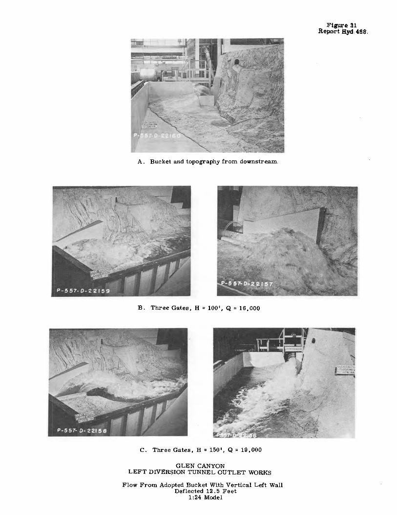
A. Bucket and topography from downstream
B. Three Gates, H = 100', Q = 16,000
C. Three Gates, H = 150 1 , Q = 19,000
GLEN CANYON LEFT DIVERSION TUNNEL OUTLET WORKS
Flow From Adopted Bucket With Vertical Left Wall Deflected 12 . 5 Feet
1:24 Model

Figure 32 Report Hyd 468
A. Three Gates, H = 200', Q = 23,000
B. Three Gates, H = 300 ', Q = 28,000
C. Three Gates, H = 410', Q = 33,000
GLEN CANYON LEFT DIVERSION TUNNEL OUTLET WORKS
Flow From Adopted Bucket With Vertical Left Wall Deflected 12. 5 Feet
1 :24 Model
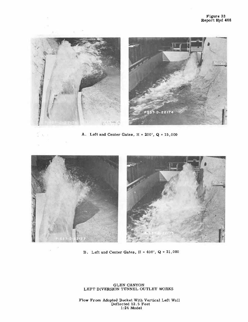
A. Left and Center Gates, H = 200', Q = 15,000
B. Left and Center Gates, H = 400', Q = 21,000
GLEN CANYON LEFT DIVERSION TUNNEL OUTLET WORKS
Flow From Adopted Bucket With Vertical Left Wall Deflected 12 . 5 Feet
1:24 Model
Figure 33 Report Hyd 468

Figure 34 Report Hyd 468
A. Prooosed 1st stae:e construction
C. H=150',Q=l9,000
E. H = 410 1 , Q = 33,000
Three Gates Open
GLEN CANYON
B. H = 75'. Q = 13,600
D. H=300 1,Q=28,000
F. H = 410 ', Q = 33,000
LEFT DIVERSION TUNNEL OUTLET WORKS
Flow From 1st Stage of Proposed 2-Stage Bucket Construction 1:24 Model

Vent closed
Vent closed
Vent closed
A. Q=5,000cfs
B. Q = 10,000 cfs
C. Q = 15,000 cfs
GLEN CANYON LEFT DIVERSION TUNNEL OUTLET WORKS
Effect Of Air Vent With Low Velocity Flows Over Bucket Lip - 3 gates full open
Vent open
Vent open
Vent open
Figure 35 Report Hyd 468

595
FIGURE 36 REPORT HYO. 468
~1.251~ ~ I I ,,/ \ /--Initial location
I ! ,,/"" ',, I , I
'!".• .... , ','J... •.':~·. I~ ,)"("' <!
~ I >t / ~ ..
-~~- ~.)(. ', -.~ ', )' 1 1mproved location
I ,,
I. D. Vent
·-~,.:
A. LOCATION OF MODEL VENTS - 1:24 SCALE
Bucket lip, El. 3157.00.) s"-+1 ~2'..o'~ " I I· I _t _____ ,: I
=~--:,- /---30" Dia conduit , I I I I
/ ,,,---EL 3152.50
B. RECOMMENDED PROTOTYPE VENT
GLEN CANYON LEFT DIVERSION TUNNEL OUTLET WORKS
AIR VENT FOR FLIP BUCKET
GPO 8414111