J} - digitool.library.mcgill.cadigitool.library.mcgill.ca/thesisfile51989.pdf · has been,measured...
152
" -', J} EijTRAINMENT OF PARTICLES FROM AGGRIGATIVE tLUltn-ZED BEDS l, (7 t< , by " .. . / Bafa Edward George Il , , l' \ A Thesis Submitted to the Faculty of Graduate Studies apd Research in Partial Fulfilment the Requirement fpr,' ,the Degree of ,Master of E;ngineerinq 1\ " " .tJ:. , , r' \ ' " , Chemical MeGill University Monqeal li ' Auqust 1976 1''' .. ' .. b /,,' ,l'l' ... 0 1 , 0" " , b IJ! S P. .S J 1 '- j 1 ,
Transcript of J} - digitool.library.mcgill.cadigitool.library.mcgill.ca/thesisfile51989.pdf · has been,measured...

"
-',
J}
EijTRAINMENT OF PARTICLES FROM AGGRIGATIVE tLUltn-ZED BEDS l, ~
(7 t< ~ ,
by "
.. . /
Bafa Edward George
Il
, ,
l' \
A Thesis Submitted to the Faculty of Graduate Studies apd Research in Partial Fulfilment ~f the
Requirement fpr,' ,the Degree of ,Master of E;ngineerinq 1\ "
" .tJ:.
, , 1\;~t1 r'
\ '
" ,
Chemical En9ineeri~9 MeGill University Monqeal
Depai;~ent li >:~ ~"I ' Auqust 1976
1''' '~},.., .. ' .. ~ b /,,' ,l'l' ...
0 1 , 0"
" , b IJ! S P. .S J
1 '- j '~
1
,

0-
• ' li 1
i
. b ..
ua;
-ABSTRACT
The volume of particles'ejected into the.~reeboa~d .;
by single bubbles erupting\atqthe surface of a fluidized bed
has been,measured for three materials: FCC catalyst, silica
&\nd and ballotini. The volume of ejected particles, norma-.
lized with respect to bUQble volume, increases ,nearly linearl~ " '
with bubblé volume for the conditions studied. The velocity
distribution.of ejecteâ particles has 'been deduc~d from experi-r"
men~al vertical profiles of particle volumes. Eject~d particles
have velocities of the sam~der of magnitude, but generally ,
larger than the velocity of the bubble causing 'the ejection,
with SOt of the ejected particles having an initial velocity of
2.1 u~ or greater. It has also been shown that thé vast majo
rit y of ejected particles originate from'bubble wakes. A simple
mechanistic model has been proposed for predicting entrainment .I 1
curves and the transport disen~aging height. This model takes
into acqount the bed itself, the freeboard region and the inter
face. It is based on
function derived from
Deviations between
r~cal correlations proba~ resu~. from - ~
wall effects, particle interacti6 s, '<?
particle segreqa~on in
"
"Jo .' ,u ... <. ; ... 1
results or empi-'" choking affects, sid~
~
recirculation
,C
--

-r
f
j , 1 ... / /
-ii-
1 ,
RESUME , '
'Le volume de~. particules qui sont projet~es au
dessus du lit par des bulles isolées qui font éruption â
la surface d'~n lit fluidisé a été mesuré pour trois maté-. '
'~ riaux: catalyseur, de cr~qu,age de fluides, sable de si'lice
et ballotini. . ~ , ,
Le volume des particules éjectées, normalisé
. '.
par rapport au volume des bulles a~gmente a peu pra~ linéaire
ment avec le volume des bulles pour le's "'conditior'ls étudiées.
La distribution de la vitesse des particuies projetées ~ été , ~'" - - '1'
déduite des profils ve):'ticaux, expérimèntaux Çles ~-6lumeso, des
partidules. Les particules projetées ont des vites~es a.,/ , .~
m~e ordre de grahdeur, mais généralement plus 6levêes que _ 1 •
, '
celles de's bulles correspondantes, 50% des particùles éject~es - . ' "
ont un~ v~tesse initiale de 2.1 UB ou supêrieure. ' On a pr9uvé, '\ ' '.
aussi, que la majorité des particules éject~es proviennent du .... .1 •
, '\ ~ '. ,
sillage c des bu~les. Un mOdale mécanique SJ.~pl~. ~ ~ 'propo,t
pour la P~diction'd~s courbes d'entratnement et de l~~auteur , " de dégagement. Ce modèle tient compte de l'a phase dense "" ,
, . , "-
. " con'benant les bulles, de l' espace l~bre a~ gé's"us du 'lit ~lU~~. '
disé et de l" inte~face entre les de~x., .-S~, f~o?1~le est basé ", ''''''J ' -,; ~ -
1 sur la fonction de dissipation de la vitè,j:-'~ de la bul'le d~r,!- " >"l~':- t
1,~ t fi, vée de la théorie de la d'issipation des je~s libre:$': ' Les ", "f' / i
. . ~! fi' ,
",.,..." , .4, ..
.... ....

'~ . ~! l '\
h, i
, , ' ! ;, .., , ' - ~ ~ ,-.:t ~ ,-. ., } . -
""";,-'"-~"""""'.~' <.""~~~~ .. ~,...'~...........-.... _"'>!: ... '"' ... :'Y>*,,""''''''~~" _____ ~~~~ _,~_,_. ___ '~'_"'_~'~"'_~-_""'~~"""" ,".-. ~-"'"'!"'_. c""'"
! ~!
~ -iii-
fj
\~
\iffêr.ences ~ntre le mod~l~ et les rêsuLtats . ~
ou ~es cor~êlations .ernpirt,ques pro iennent
d'effets d'engorgement, ~'effets d p~rois
d'interactions entre pa~~~cules, de rec~rcu des pal7ti-
cules et de la sêgrêga ~ion des parficu es ans le lit même. 1
(
~
1, (, .~
j
! t , '
>
r 1
/
, \
, '''''A , D
" .• 3"':
1 ,.ç
r
1"
y
J

\
"
)
'. , Q
-iv-
ACKNOWLEDGEMENTS
l would like to express my gratitude to my' research ,
supervisor Dr. John R. Grace for.his gUfdance and help in the
~ompletion of this work.
Thanks are alsordue ~o: . >
National Research Council of Can~d~,and th~ Max Binz r
Bursary for financial support; • 0
T Mr. A. Krish~and his staff for their prompt attention
whenever their assistance was requested; ,\ \
Dr. M. Avedesian for their stimulating ~:)
discussions throuqhout the coarse of thi research;
Mr. L. Nq for his help in nq the figures;
my parent's and my brother Dhia who proN'ided me with .'
the oppOrtunity to persue my graduate education; . , , \
and Miss A. Arkiletian for her typing and la~oratory
assistance. Ir
. , . ./ 1
'-
, , '", .
Q

)
'.
III'! r
\ , . \
l' l '
ABSTRACT
, ACKNOo/LEDGEMENTS
TABLE 1 OF C6NTENTS f 1
LIST OF FI~URES
LIST OF ,TABLES
NOMENCt..ATURE
1 1 1
1
.1 "
TABL& OF CONT§NTS
: 1
~ 1
p
CHAPTER 1;,' REVIEW AND COMPAtuSON OF EXISTING CORRELATIONS FOR THE PREDICTION OF TRANSPORT DISENGAGING HEIGHTS AND ENTRàINMENT RATES IN FLUIDIZED ~EDS
Il 1.1. INTRODUCTION , 1.2. TRANSPORT DI-SENGA~ING HEIGHT
, \ \
1.2.1. Introduction' a 1.2.2. Existing correlations
1.2.2.1. Zenz and, Weil 1.2.2.2. Soroko, Mikha1ev and Mukh1enov
? 1.2.2.3. Fourno1, Bèrgougnou and Baker 1.2.2.4. f .. Çheremisinoff and Rao .. 1.2.2.5. Do, Grace and C1i~t
C'
1. 3.. EN'l'RAINMENT AND ELUTRIATION
1.3.1. Introduction 1.3.2. E1utriation 1 •. 3. 2 • 1. Yag i' and Aochi
'v, "1. 3 • 2 • 2 • Wen and Hashinqer, '1:3.2.3, Zenz and Weil
\ '\ ,
\1'.3.2.4.,. Lewis, Gi11i1and and L4ng. 1.3.2.5 •. F~~rno1, Bergougnou and ijaker
. . ....
<S . "
; 1 $ i)l., " .
Page
i
iv
v
, ix
xi
xii
1
1
2
2 2 4 5. 5 6 6
8
S 10 10
L 10 11
":- 1,2 13
, .
Il
, 1
t
~
r 1 Il
'il' 1 ~ tJ-!...,.....,.u.,,-t ... ''''i.,,-:-,.,.~--t~,-..-.-~_ -~+i- .... 'r
. "\,
0
•
,
! 1
(\ i
i.~.2.6. 1.3.2.7.
, " . -V~-./
. Merr!èk and Bigh1ey Leva and Wen
1.4. .. RESULTS ,
1. 5.
, 1.4.1. TDH Results 1,.4"2; E1utriatüm Rate Results
CO~CLUSIONS AND JUSTIFICATION FOR FÙRTHER RESEARCH
•
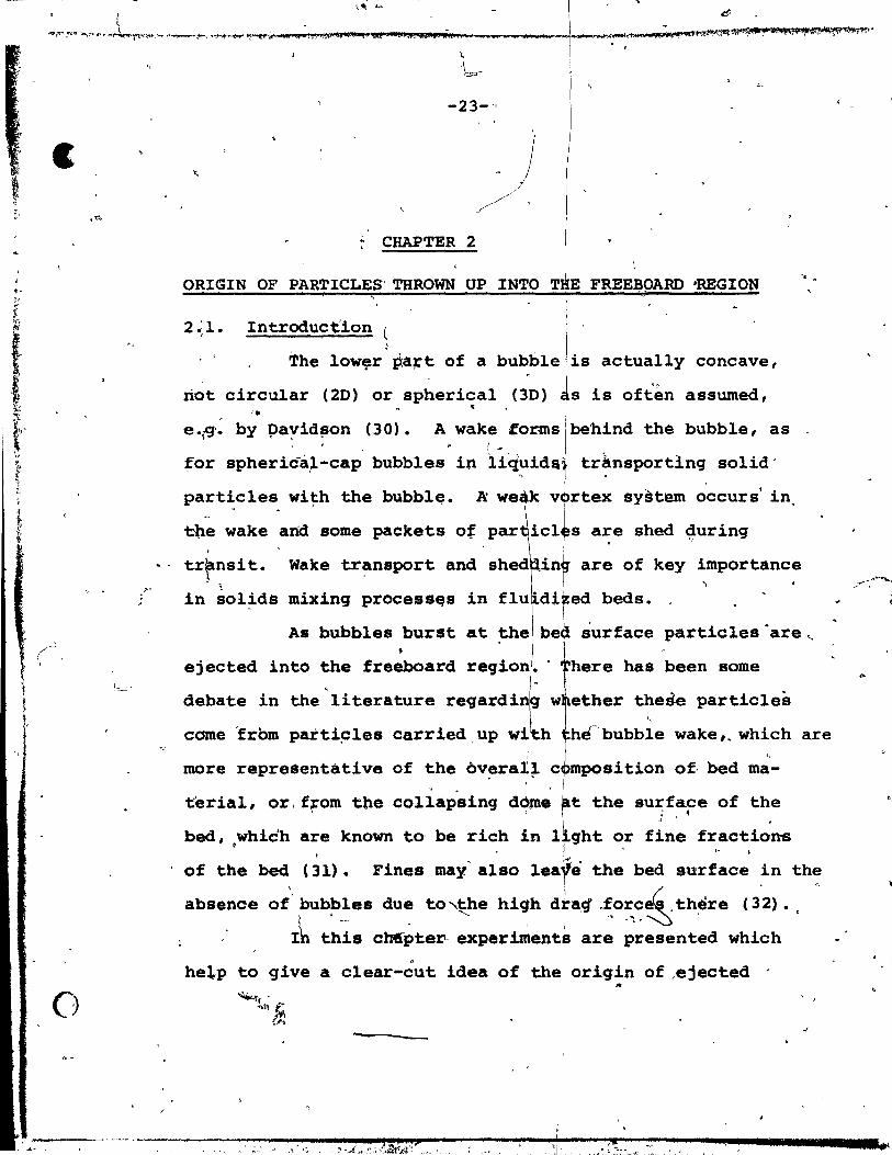
CHAPTER 2: 9RIGIN OF P~~ICLES 'l'BROWN UP INTO
2.1.
~~.,~ . 2.3.
2.4.
~ FRE~BOARD REG~
INTRODUCTION ~
PARTICLE CATCBING DEVICE
ISOKlNETIÇ SAMPLING /
EXPERIMENTAL
2'.4.!. 2.4.2. 2.4.3. 2.4,.4.
Equipment , Calculat~on of Bubble Diameter Experimental Procedure Separation of Coke from Sand in Analysinq Collected Samples
2.5. RESULTS AND DISCUSSION
CHAPTER 3: V9LUME OF EJECTED PART ICLES,
3.1. EX~ERlMENTAL
"
\ , 3.1.1. Equipment and Materials 3.1.2. Procedure
.. 3. 2. FRONTAL BuBBLE DIAMETER
3.3. NORMALIZED VOLUME OF EJE~TED PARTICLES . AS A FUNCTION OF BUBBLE DIAMETER
" .
"
3.4.' PARTICLES CAUGHT' As A,FUNCTION OF HEla~T AND DEDUCEO VELOCITY'OISTRIBUTION OF EJEC~ED PARTICLES , ' " .
Page 14 15 '
17
17 19
21
23
23
24
26
33
33 34 36 38
3"9
43
43
43 46
49
49'
53
•
"
Q
,il Il
l.
)
'II ,
-",~~-
,
1 i .'
q
, J
'01
1
' ..... ;
~ ~,..I!'~' ____ "~"" ___ "'''''''I-"~.",,, ",~~"",'''(f ,_~~_'*'t lI:.o?IHe e 'i!f.!'-~~~~.""'_'-J _____ ___ 4' __ .... ....r~_, __ .... ,.....,. .... 'ff~.I""1 .... ~r.il.' """l'I~'<j....,..!~
"
CHAPTER 4: MODELLING OF ENTRAINMENT FROM FLUIDIZED BEDS
4 ;1. BU~BLE DI~TER\CORRELATIONS
4.2. BUBBLE FORMATION BY INJECTED GAS
4.3. BUBBLE RISE VELOCITY
-+'4. VISIBLE BUBBLE FLOW
4.5. BUBBLE VELOCITY DISSIPATION
4.6. ENTRAINMENT MODEL
ÇHAPTER 5: . APPLICATION OP' ENTRAINMENT MODEL
5. 1. MASS FLUX OF EJECTED PARTICLES AT THE SURFACE OF THE BED
'-.-, Page
59
59
69
70
71
72
75
80
80
5. 2. ENTllAINMENT ABOVE THE 'l'OH (ELUTRIATION RATE) 81 ~ . 5 • 3 • ESTIMATION OF 'l'HE ENTRAINMENT CU~VE
5.3.1. Mass Flux of Partic1es 5.3.2. Mass Concent~ation of Partic1es
5.4. CONCLUSION
; CHAPTER 6: DISCUSSDONS AND SUGGESTIONS FOR
p:uTURE WORR ,
6.1. VERTICAL PNEUMATIC CONVEYING
6.1.1. ~.1.2. 6.1.3. 6.1.4.
Introduction
J .,' 6.1.5. , "--'-~-:-~ ~.-1-.. 6 .. "
Zenz and Othmer . Leunq, Wi1es and Nick1in Nakamura and Capes' , Know1ton and Bachovchin Resu1t~ and Discussion
t ,. • ,
J\ --,~ 1 '6 • 2 ~ ,,!. WALL EFFECTS
J~ ..
6.3. !~; t»ARTICLE SEGR!:GATION IN THE BEO
84
86" 86
96
98
98
'f '(~~ 98 '1 99
99 101 102 102
105
106
'.
f,
\,

o
/
... viii-
. 6,.4. BUBBLE SIZE DISTRIBUTION'
6. 5. EFFECT OF PARTICLE INTERACTIONS IN THE FREEBOARO
.J 6.6. CONCLUSION AND SUGGESTIONS ~bR FUTURE WORK
J
APPENDICES
" ' (A)
(B-F\
Procedure for Calculating Elutriation Rates
Operating Conditions, and Elutriation Rates qompu~ations
(G) Statistical Tests to Establish Effect of Suction Pres8ur~ on Weight .of Collected . Particles
Representative Particle Collection Rèsults "
(H)
(l) Partiele Trajectory Model Computer Programme ~
o . REFERENCES \~
. ,
Page
107
108
"' 109
110
110
113-117
118
,121 '
1;27
133
»
1..
" '
, 1 • ..
•
1
~ 0
1)
Figure
l. .. 'l
l.~
2.1
2.2
2.3
2.4
'r
l ,
2.5
3.1
3.2
~.3
3.4-
3.5
3.6
'.
",
. ' "
-ix ...
, '
LIST OF FIGURES
.. CaPtion
Effect ôf stratification.on elutriatian for glass spheres
Co;relation of elutriation for single size gla8& sphe~es ~
Side' view~particle catchinq device
Representative and nonrepresentative particulate .amplinq conditions
Simplified' line diaqram of th, bubble inj action device ' . ..j •
",
,Page
16
16
25
27
35
Line diagram of the genera! exper~ental 37 setup ,
Weiqht fraction of surface partiel es .captured as f~netiQn of trae,r 1aye~
~ thickn... . ~ i,.
Determination of the minimum f1uidizing velocity for silica sand
"
Geometrieal construction of a typie~ area from which ejected partielê re eollected
41
Frontal bub~le d1amej.~ver,.us (vo~ume 50 of injeeted bubble)~ 3 ,
f. ., Normalizéd volume of'ejected partiçl.s as 52 • function of buPble dlameter ~~
vertical profile of'partiele volumes at d·ifferent height8 ~n the freebOard - ' \ Radial profiles of partiele volumes _\at different height:s in the freeboard 1, , ,
f
\. .
'.~'
54
55
, . . .....J.
• 'J
, '"
'.
}' 1.
",
•
"
1 l
•
.i "#
''Pic;ur E7
3.7
4.1
4.2
.. 4.5
4.6
, 5.1 ,1
,
.15 • 2
,"'
,/
5.3
5.4
s.s S.6
S.7
5.8
S.9~
. "
..
l "
.' /
\
;'. " ., ' , ' " l' •
4 t; ... ' ~.. .. i U HtU .. bt M".. 44 il" ,~;. 'J Uwau "",, el! :~
.~
. ~ • 1 . < •
ca~tj.on
Cum~lative distribution of particle vertical ~jeetion.v&locities
Bubbl~diametér versus U - Umf ' . Bubble di~ete~.versus heiqht, f,or U - Umf -i 5, 10 cm/s .' , Bubble di~eter versus heiqht, fo~ iU - Umf - 13,19,.31 C$/s
Bub6 e d1~.ter ver.u~·u - Umf ' tor. • 2S cm -. . , , . Bubble diameter versus. U - Û f' for, three, different bed heigJhr.8_.
No~lized gas velocity in .~~ freeboàrd reg ion ," ;':
.... 1 . "
. 64
65
66
67
68
, 74 /
" 1 ,
, . " ,. ..,.
J
0' Pârticle size distribution of Fce 85, 'l
" Practional mass fluxes for D • 225: andL150 ~m p
To~l and f~acyional mass'fluxes (96~' 59.5 and~9 lUIl)
, . ,-~ "
Mass D • p.
Mas.
concentration curv.s for 150' llm
copce~tration for D - 96 llM , ~. p " ~
Mass conc~ntration,for'Dp - 59.5 llm
Mass concentrati~~ for Op - 29 lJ~ , Total masa conee!itra.tion for Dp .,96, 59.5 a~d 29 lJm . . Total P4rticle ~ss concentration in
' .. the freeboard . ,
. , l '
si f ' '
,87
88
89
, '
90 '"' 'if' .~. ..-.... 91" . ,....;,.-,;~
92
93
95 f"
. ,
" , .~

'-
, ; r
.f •. . r
" (
,~)
,.
, ,
J '>f'{l J.. ':/';1,.'
•
..
b
. "
Table "l', "
'1.2
1.3
1.4 î
2.1
2.,2
3.1
4.1
4.2
5.1 )
~
, ........
, . . - .
.. -xi-
1 ,.
;
,.,
LIST OF TABLBS
Title
,-
Eltperimental conditio s for 'entrain-ment and transpq senqaginq heiqht in fluid zed beds
ms results
, Elutriation ra>e results for~nd 1 IM..utriation rate reaults for FCC
./ ,
Weight' of collected partieles: va~iation w!èh sucti~n pressure
Oriqin of ~articles expertmenta1' re~sul~, '
.< Material pr1perties ", ,.," r, ' , ,
•
~
l' .' Exp8riinent~l work, ir~9ardinq bubl?l:e .-. J -
, . 'populations in ,fr~ly bubblinq~ three~dimensional fluidized beds
o
" S~unmary of bub~le diameter correlations
,for freely bubplinq fluidized.bed~ . ~ ... ... r'f"r r.
.: Re.ulta (or par,t~cle mass flux at the surface '
.. . 5.2 'Elutriation ra~e re.ulta
;
6.1 "Super~icial solld mass f1uxo rates ~
.'
\ \ ~ 1 ,
.::
" ) . ~
.,;,. .... , Ji.
, ft
'. l,
.. 18
" 2> ,
20 .""' ~
31 1 -.J..~
.~
40-
'44 !
60 . ' . ,"",
:-1'
"
,62
82 if.
~ \j1
83 , . '"
104
c
-,~ ,
."..
1 • - ~
t.-

<·V ~,
•
.; . ~:jçr,;ç!i&.fJJ4u+ ; iA.=-EtifDJ( lP+'. 4 3".";»4 S 41$11.'24 li'''.M.I'' •• ' pm J J 6 .... lA iAé'NU U ; 1 l
.... ii@iiJfk""A .... ~.t4"_._, ",,,, •
J..' •
1
--1 . ,1-' .... J
/ .
1"'.
~ <'
(_
'i,j
fp
fW
G y
.9 ~,
GB
-xii-
)
NOMENCLATURE
" bed cro.s-8ec~ional area
drag coefficient
total concentration of particle species i
concentration of particle of size Dpi and initial velocity v j
measured particle concentration
true particle concéntration , r
,bubble diameter -~,
'. ,
, , ,
, ~on~l diametc:r of
, partie le diameter
the·e~upting bubble
1
average ~article diameter , .
"~tlqa~ partie le di~eter di*er of the veuel .
entrainment flux
Mo> flux of particlesvat the ~urface
flux of par~cles of 8ize I?pl and initial ! "l~it~~ ~~
partie le-wall friction 108ses " ~,.. ~
fraction of bùbble occupied by~he wake ,/
superficial so~id mass flow rate ;;
acceleratio~~e to 9r~~ity
visible bUbble flow rate '
.. .. , •
J
..
" .

\ .
(
. '. "~.~ 1 itJ ............ uô ...... ~, ........ ,. al ,,,"p,",,,.:;,,' ~"""'~,*,,'~".I!"II!MVI!IIII!IIII'QI!,*,ltJflPlle ... ae"""d ____ ._,._._.""'''''' .......... _*''''''''''. __ 6_. _av ... "'_e 1Il!I.1&"""; """"';:"'''''"..,li4f'1l11'''P' ""'! .... """""""M""', .............• -...
h
h max
K*
n
t
° UB
,Ueh
°mf
Os
°sl
,Ot
Ux v
v
fi: ,
'" 'F "
. -xiii-
variable heiqht
max~ height reached by a freeboard
static bed height -.. ., e~utriation constant
specifie elutriation rate constant
total number of holes in the·distributor ? .
., 0
radius of jet at the orifice
volumetrrê flow rate of 8011ds o
standard dev1at10n
time
superficial ga8 velocity
bubble veloe1ty
chokinq velocity
min~ flu1dizing velocity
auperficial 8011d velocity.
partielé slip veloc1ty
partiele terminal velocity
centre lin. velocity of ga8 jet
partiele val ity
bubble vol
average gas ~eloeity
initial partiele velocity •
veloeity of qas sample in nozzle
t
•
-~ . - , . , ~
.~- t' .... ,'~"Iif ! .... ,~~~~_,~ .... j* i!tl's/;'IlJiW_~.1iIJ"9l$l_:t.~~~h,_ 'JiUW*i\A\M~~~~t.~\~~1i'''''"'-r'~''''~'''·;''··'';··'''rr--''' ".'
\",
1 1 ,
v ps
Vpt,Vp '"
v ·s W
Wch W -
0
Wop < -Opc Wio
,.6
x
xif xit
y
B
\
-xiv- l'
(
average solids velocity
particle velocity in th~ u~ard and 'downward direction respectively
stack velocity "
total bed weight
solid mass flux at choking
weight of solids of size 0 in the bed
'weight fraction of particles whose Op
weiqht fraction of species i in the proper
'sample Mean
•
< Ope
bed
volume fraction of partiyles in the bed '. volume fraction of particles in the riser
(freeboard)
normalized centre line veloci,ty of gas jet
normalized distance
Greek SymbolS\
fluid density
particle density
sol id density
fluid vlscosity
1
voida'ge' of suspension at ehoking cond~tions , -=--~- ('
-voidage at minimum fluidizing conditions
volume of ejected partiel es normalized with respect tO,bubble volume
., •

! ' . , .. '
" , .
1 . ' "
If "~~~~~_In_<j,,g, ........... J:;_'I ~_.~ __ ~.~ __ .......,_. ___ -.----...-_;of~_""'IL'I' .... _'!:!!I"'.~!i9"'~1"~ .... "...- .. .,.,\ t-~<._...,..~_ "
-1-
. CHAPTER 1
, 1 '.
RÉVIEW AND COMPARISON OF EXISTING CORRELATIONS FOR THE PREDICTION OF T~SPORT DISENGAGING HEIGHTS AND
ENTRAINMENTrRATES IN FLUIDIZEO B~
1.1. INTRODUCTION \
The prediction of 'entrainm~nt rates and transport
diseng4ging'heiqhts is an~Jmportant àspect of fluidized
. beds, affectinq the size of the column and of sepa~ation
equipment requ~ed. A.fewapplications exist in which
elutriation of SQi!ds is~,t to good advantage, e.g. for
~ " separ~tion of valuab1e con tituents in a mineral from ma-, . terial of low or high densi ty. In addition, .there is evi-
",
dence (e.g_ 'see (l)J ~ substantial frac,!:lon of the over-"
al1 conversion may take place in:the freeb6ard region of
fluidized bed reactors. In some p~oeesses (e.g_ see 2 ),
the solid product str~am is taken~rom partic1es collected
by cyclones. It is therefore ~Rortant to be able to pre-• 1
dict the flux and concentration of particles above a dense
phase fluidized bed as.a function of op~rating conditions.
and equipment v~ables.
At t~e presenf time, entrainment rates and trans
port disengag'inq heights for f,luidized beds are genera11y
based on one or more empirical or semi-empirical correlations.
Thare are a number of these 'to choose from (3 - 12). This i" 1
chapter'presents a criti~al re~ew\ofl Many of these correla-1
! .
r.

•
"
. ' 1
.,
tions and some comparison of their predictions.
1.2 •. Transport Disengaginq Height fi
" 1.2.1. Introduction /),
The section of the vessel between the surfaée of
the dense phase and the top of the vessel is called the )
, . freeboard. The p~rpose of th~freeboard is to 'disengage
solids from the qas stream. . r--
Bubbles erupt·, at the surface
of the bed ejecting particles into tne fr,~eboard region.
This bursting of bUbbl~ls~ causes an irregular velooity
profile Across the freeboard (3 ,13). Some distance above
-the bed sur~ace, the velocity tends to become more Uniform
and,smil1 partiel es are carried away with ~e gas st~eam, ~4
their ~erminal velocity being general1y lees an th. superfi-, 1 ' , cial g,as velocity.'IIt Large particles generally fall:back to
the be~ surface due to their larger terminal' vel~cities.
The tr.nsport disengaging height (TOB) may be defined as ~ ~ '\. ,f
the he~ght of the vessel which is re~ired',o,dis.niaq~
these ~arqer~article8. from further; upward movement. 1 .,(,
1. 2. 2. :, Existinq Correl"a tions . . r: , {::1 • •
, Table (1.1) sununarises work done ~o
correlation for the calculation of 'ITOH. 86me
deviloP a general
of/the findings
'lit S~e experimental observations (2 ,13) show that'in pra~tice a s~ll fraction of larqer particles with Qt
, !arger than U also find their way out of ehe Ded. , !
. ~ 1 j
•
1 1 j

_'1 ; 1 leM,: -~V.'1"'7'1!f'. _ & 2 )))iJ4lJU'- _ _ ~a2L4 il glaSSJ tS.!t 1 Je lti.~.,.-:,~;-"~:-c,-
-. ft -.; '1 ~."
)- ~ , .....
. -:: b.~,"'l~ -. .!~. ;1' ot".x ..
" .. i "~~~ ~':~ -i
Investigator
Zenz and We'll (3)
.Soroko, Mikhalev, and '
For
TABLE (1.1) Experimental Conditions
Entrainment and Transport Disengaging In Fluidized Beds ,.
Height
Vessel Gas Distributor Partic1es
.....
Experiments Characteristic (cm)
Superficia1 Gas Ve10city
(cm/s) (cm) - . --Entrainment of Dt =5-S00 Air
FCC, Steady State operation
Dt =20,30,90 -
Various Designs
, Various Designs
FCC with Size
Distribution
Abrasion Resistant Cata11'~t o =0.075, 0',:1,
p ')..;::}'J
30.5-152.5
Muhh1enov ( 4 ) ". \".,,~ ,O. 15, O. 25 . 'j: -i
i!-: !,~
,.,
lournol, Bergougnou, Baker (5)-
Yagi and Aochi (10)
~- 1 Wen and :~ Hashinger "_ .. ' (11)
l 0 •
LeW1S,
Gi11ard and Lang (9)
Merrick and High1ey ( 8)
Entrainment of Fee, Steady State Operation 1
D =61 t
;Air " ~"'\
Grid
....
FCC, Geometric Mean Dp=58 \lIn by Weight
-ElutriatiQn, 2 and Multi-
Dt-S.2,7.l -Air Fixed ,.sand,
Bed of Seed. Glass,
'comPOllent . f\nf:;3.1-12 Batch ana Steady St;ate Operations E1utriation, 2 Dt =5.1,10.2 and Multicomponent
Air, Be
Batch Operations Entrainment, 1 Component Steady State
Elutriation and Abrasion, Batch and Steady State
Dt=1.9-14.6 Air
Bmf=10.2-71 ,
Cross-section Air 91.4x91. 4
and 9l.4?<45.7
Steel Balls
Fi1ter Cloth
. -Glass Spheres, Coal powder
Wire Mesh Glass, Iron, Screen on Polystytenè, Fixed Bed CC
Coal
<"
;,
, 11-22
92-1
1"
22-132
28-476
'. " 61-244
-.
• ,
Internals
None-
With and Witho~ . stabili ing Grid '.
None
;.!>,
tI!-=t
." None
-...:: .. ..., - ~r
1 w 1
<;>
, ,
With and without 'Stirrer or Wire Obstruction
None
-;)
,'>l-.. ~"t ........ ;.~
) "': ..
"
i
l 1 :
l ~ t ~
î j
i \ f
~
1 ~
~ r-1
j ;
t i ,
,1_ teh? hu .. · ... )I?cre~~·.br,d 7'rt")"&0 d€t"t't't .. p .,. rHtmrtWt*2t'r'r$tc $S'$té~tis'!t,=W,:.,. ... ,s SP"S-iPSttt-ptnm 'f"~.''fs .. nH'UgttVtfV~~~~~, .,n~ ...... ~.(.~~_; s1È;;;rtTlrr~

L ~ .1
(;"
1
. '"-~:,.,._~~~-.-,.-~-,..,~,.,..,._, -.• _~,.)~"",~ ,...,.."ii{..~"",~:.........,-,...,.,~ .. ,~~,u~. _~, ~._ . __ .:. __ ~ ••. ~, _, •. _ ~'"" . ~'" n~'-"-f--' ~ . ..k- 1-- • 04: J.
,<;1 i .....
-4-
of various vestigators are as follows:
1.2.2.1. Z nz and Weil
(a)
/'
spherical
his model expresses the par~icle velocity, v, for
articles travelling above the bed without collision
and unde~,a conatantaverage
v • vi exp (- at)
gas velocity, U,
- (Ut -,U) t
as: )-
f.' where a - 18 ~/pp O! ' 1
(1.1)
and vi - initial ve10city of ejected partic1e •.
This equation was derived by integrating the egJation of
mot;on' fo a part.!cle. The maximum height tra~elled by
coarse partic1es was derived as: 1 / v
max~um • a- (vi - (~U) ~n (1 + ~Ut--F~u ) )
kno
can be used to estimate the ..
Th~ shortcoming of this. correlation , ,
is t; o once Vi
uSe of
(1. 2)
drag-Reynolds numb~r relationsh' in lts 'derivation. . (b)', Empirica1 Correlation
Zenz and +il (3) also presented
gra hical COrrel&tiJn Wh,ich relates the TOH
n empirica1
o superficial
gas ve10city and bed diameter. The correlation is np~ app~i-\
cable either as U + Umf where TOR approaches zero or as
U + Ut for the large~t particles where lar~e scale pneumatic
~onveying occurs. Another limitation ia that the correlation
makes no reference ta gas or solid properties such as density. ''if"
The correlation was based on data taken under a variety of
operating con~~ions, but with rather smal1 (principally
" m._......-___ ---.-.·_ .. r_ .... --. ________ • ii"'.-----" , ..... ,,,,'" .:--,

r. ,~ ,
Î
.,.,..." 1
-5-
cracking catalyst) particles. For these reasons, the eorre
lation should be considered merely to give an approx~te
and rather conservative estimate of 'l'OH.
1
1.2.2.2. Boroko, Mikhalev, and Mukhlenov
Soroko et al (4) developeÇl empirical èorrJlatio~a for calculating the minimum freeboard height,.TDH, with and
, w{thout a stabilizing grid. ' The" correlations are as follows:
'!'DH ,. 1200 Ho Râ· 55 Arl • l (Ll) '(without stabilizl,ng grid)
and 'l'OH - 730 Ho ,Re1 • 45 Ar l : 1 (1.4) (with stabilizing grid)
The first of these correlations waal' reported to be valid for:
lS < Re - ~ < 300
'" g03 P -P f
19.5)( 103 < Ar • .:.=:t-.~ < 650 x l0 3 , v 0 ,p f 'r
Partiales of abrasion-resistant cata1yst with diameter, Op' - l
of 0.075, 0.1, 0.15 and 0.25 cm were used in the experiments:
The maximum height of ascent of particles was measured using
motion pictures. The above correlations do not describe
comp1etely the ejection of 801id particles, the mechanism of,
which requires a more profound study, but they can be used
to give onè'estimate of the TOR. ~ .
1.2.2.3. Fournol, Bergouqnou and Baker
The set of ex,périments performed by Fournol' et al (5) , "
confirm the existance 9f a TOR above whie~ the entrainment
,..', ... 4** l' ,l'

• ,r;:
, " "'1
~;{,?'t-">~""'?*"",~".,...,.-......-..,yt~_"""""'''''' ...... ~1r'?' • J):! ~.~ .. < .. +" • .,~--.-_~~_ p __ ~_ ~ __ _
_ ______ ,. ___ .. _ ......... __ "' .... 1" .. v.,--i-"
rate and Mean particle size become essen~ial~ constant.
This TOH cou1d be corre1ated in the expertments reported as .., , the heiqht above the bed surface at which the inverse" Froude
n~er, gh / u2 - 1000 2
Therefore,TDH - 1000 ~ (1.5) ""
''l'hus- the TOH was found proportional to u2 compared to the
ul • 55 dependance indicated by Soroko et al. Thrs correlation •
is restricted to FCC aince the experimenta1 data were gene-
rated using FCC partic1es on1y.
1.2.2.4 •. 'Cheremisinoff and Rao
Cheremisinoff and Rao (6) develo,ed a semi-empirical
model for calculating the TOH. They used the correlation
described by Lewis et al. ~ i~ the following form:
F - F ~ exp (-a.1 'l'OH)
l'
, t f
,t,
where F - allowab1e entrainment rate which m~st be specified. ,
F.'. entrainment rate at the TOH.
a - constant, obtainable from Lewis et al (9). "
In order to use their model, the appropriate value of a ~ust be ) ,
( , , obtàin~: for the particles fl\1idized, the column diameter, and
, the gas velocity.'< The value used, by them ,to fit the data of
Taft. -(14) was 0.018 cm -1. ',:
" " 1. 2.2.5. ' particle Trajector)" Model
A simple and reason~odel was proposed by "
1
Do et al. (7) to describe the motior of ejected.particles
"~,
J 11_ ,-b

--------~------~------~'r , • v
,
\.
.......
-7-
in the freeboard. Drag forces were calculated using an
empirical fit to the standard drag curve, assuming particles . "
to be hyàrodynamica~ly spherical and neglècting particle -
particle interactions. The ~itial partie le velocity was
~, ~~ssumed to ~e aboüt twice the velocity of the largest bubble
in the bed to account for bubble coalescence (7).
The equation of 'mo~ion of the particle, derived
from a force balance can be wr~tten:
dv 3 Co Pf vR 1 vR 1 ( p - Pf g ëIt • - i
P (1.6) P~ Op Pp
whère vR • v - U ia the partie le velocity l!elative to that ,,~
of the gas stream
and db v· dt ia the ahsolute partiele veloeity direeted
yertically upwards.
Equation (1.6) can also be applied to diverging " \
tapered sections by allowing, U, to be ~ function of height, h.
~umerical integration of equation (1.6) using the fourth -
order Kutta Merson process, with the iniëial conditions:
at t - 0
~ vas used to obtain instantaneous values for v and h in the ,. freeboard.
Large partie~es were shawn to penetra te ta greater
heights than intermediate size partiales for the conditions
conaidèr~d, although the latter May hAv~ greater resiaence
, .. ,.'. .'~.'t"".;
-8 ..
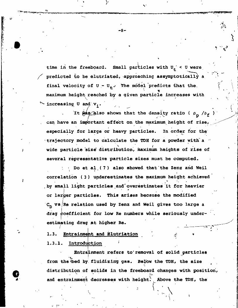
time in the freeboard. Small par~icles with Ut < U were
Î predicted to be elutriated, .approaching asSymJ?totic~ a
" .
- j 0
final velocity of U ,- Ute' ~he môdel predicts fhat the. 111
maximum height reached by a given particle increases with '\
t '
\ \ ,
~ increasin<Jo U and',vi ." '.
o "oIt ~lSO shown that the den.~i,~y rati'O ( Pp IPf ) ° • J,
can have an i~~tant effect on the m:aximum. height of rise, ___ ~~~ . o •
especially for large or heavy particles. In order for thEf !.ç.. ~
'trajectory model to calculate the mB for a po~der ~itl'ï a -. - '... ~ "
wide particle 'size distribution:, inax~um heights of rise of
seve'ral repres~ntative partic'le sizes must be computed.
: . Do et al (7) a180 showed tha t . the Zenz and Weil '; ...
correlation (3) upderestimates the I:UXimum height aéhieved "
.by ~ma' 1 light particles.and·overestimates ~it f~r heavier . . or lar er particles. This arises because the modified
'ÇD Re relation used by Zenz and Weil gives too large a , ,
drag oeffioient for low Re numbers while seriously under-
ting drag _t higher Re.
1. 3. t and Elutri'ation
1.3.1. Introd tian 5
/
--'--~ , . ,
nment refers to'removal of solid particles -, -~, .
from the ~bed by. fluidizing g&s. Be~'bw the TDH, the size
distributi~n.of ~o~ids in the freeboa7d changes with position,
and entrainme"nt decreases with hei9ht~';'o- ÀbOve the TDB, the' -, r /' .
~ :. \ 1 \

--1 .... , ... ~. •
~ ~".* .. P"':(t $'13III"0;"",;p M4,*,\lif;l),*,j;lj!~"tti" t";II~"'*."""'1t ZAd'" a*"i!f.ItMlIi m,"" 1""" -..tt1lI.!-, _~ __ ...:)~_ .. _1_ .... 4**' .... ' .O!!jeAlWidj "",""",..,.";.~!L.;*=<jil~~1t . ,'tt; ~ r . "
c" ; ... -
\
size distribution and entrainment rate ~ecome constant ( 3 , 5 ) • 1... ~ 1 ..
. Elutriation is the proêess whereby ~ller par~icle~ . -fJ
are eontinuously removed f~om a bed composed of a ~fctrum
o~ particles of different sizes.· In a con~inuous op?eration
of a fluidized bed, fine particles may be ôr~qinally pte
sent, or they May bè'pr~uced from ~arger particles by attri
tion -( 8 ) •
Elutriated fines are usually returned to the . ~
system by separation equipmen~sueh as cyclones or e!ectro-
static preeipitators in orde~~ min~ise catalyst cost~ , t
abate pollution and maintain' reaction rate; ·(15). A knowleëlS}e ,~, 'II ~"rfittt, ;S"..,. 1 "). 6 't
of entrainment above the bed is ,necessaty for the efttcient 1
design of solids recovery equipment. "
,. 1 ~ •
Nwnerous entrainment studies...:have been,. ca;ried . ! l '" , _ 1
, l)'" .. 'f'
out. Two factors ,haVt hirtdered qeneral applic~tion of the • ,r ...
resul ts to ~ommf'clal flUidiz~o bed desi~n. FArS;'l ma t
inveatigatora '(e.g. Bynian, Lev. , and Osberg) have wor ~ o ~ ''7 f ",
on single component or two component partiel~ siz st"ems1
these are not representlltive of ,commercial ~nits. ,·Bed , ,
, " f
hydrodynamiclJ may differ ~n the ,two cas~s sinee ft smdbth· , ' '(" ,
fLuidization ià promoted by a wide distribution of partie le . . siies. Secondly, most etudies were conducted in small co-
'.. ) (~ 1
lumns of diam,ter 15 cm o.r 'lesa (9 ,116). rf'. ,
Theae lnveatig~tiobs i'"~ ,
prôvidé a qu~litative understand~n9 of antrainm~nt, but do .]
. ,
, 1

. ' ~
,
• ,
v l' " ... "d'..gT(\~'''''-~;'''~#~.f'!~'ft(1!l ;;t..tt~" _~""!O"'''b''';4iYii"""*" .... g44ij1"",,GJ'''''I&''''''''>''''''lWi,,"paNlaA..-UI!l\ll$&lII'lsu .... ..,a=_. ____ ....... ___ ....... _ •• __ ........ _N~J4.;.;",....,..if\'II'l!I! ... ~!llft\\llf"'''~!I ,N_fT~
."~.,. 1 , ,
( '-;;'10~
' . ., r,
not provide ade~ate data for the desiin of large 1ndustrial
beds (S·). ! )
1.3.2. E1utriation ......~ .. ~
;., • 1 \ , 1.3.2.1. Ya9:i and Aoc hi. ,,,,
""
By, ~eans .~ dimensional ana,lysis ',.r,,'a corre'lation ~ . . ~ . ~" ~
for the s~ecific elutJ:iation rat~ constant,), K*, has been
proposed bY Yagi and Aochi (10). They summ~ri~~ their 1 ~. • Ji
, r / '
own dat,a 'a~ other' data -,(17,18) in a graphie al forme " " ;.
ThÉdr . f • -.'
corre,lat'ion 'is: ,. ,
" ~
'K* 0 . l? lJf
f U 0 P 0.01'c'. ~ P f
,f
- \
1.12 }
t, (1.7) • r' , " ,<
, . '-' ~ , , " ".
'However, many inve.t~SJators .(e.g. ,Large ~et al ,(13), Av~d~$ian', .. '
( 2» have reported tha t s~me 1arq~, partie les wi th t!t 1 ~ U .. ca~
'. also be elutriated. The above correlation c~nottadc~t . "-o •
for ,this observation since it fails at~t - U.
1.3.2.2. Wen and Rashinqer
" '" ,
Wèn and Bàshinger (11) proposéd a ge~er~~ized ~-; ~pirical correl.tio~ for e~alua~n9·~e s~cific elutrit ' 1
" :tion rate cons;tant 'in two _an~ mUlti-d~mp(!)nent pa,;-ticle', . -). / l ,/ ,JJ. ':;
s~~t1,\baséd on .expeJ;"~n~~l:. da~a of Osberg and Char.J.è·sworth.t.;
(ig) ," Leva (20), Himan (21">', Yagi and Aochi (lO) and themselves. Il( , ~ 'If .,' The co;iel~tion covers the rang.:
'"
1 ~ i / i ) 311
1
~

1 ~
,.
,.
e
. , • 4# 1,. ," ~4A; 11 ~ ,. _Qi hM! ~ UtY4f U4- ~:li!
-11-Il 1
' ..
0.004 < D < O.OlS' cm p. \ "
0.00016' < pi < 0.00'12 g;'~3 • ' . 3' ~.3 < Pp~< S.O q/cm
,;. \ .
22 < Uo< 132 cm/s
and is given b~:
R* _ ~ (U 2. Ut Op 0.729" 10:5 Ut) 0.5 Pf
lia 1.7 )( ~ qD ). ( ) . Pt ( U - 0 t
)
~ - Pf 1.15 0 - Ut q.lO ""p -
( n ) (Ut ) t"f .
P ' : JJf
K* was' found to be independent of fines concentration uP'
to 25\, but abOve 2~' K* was found to decrease. For high -
fines concentrati~n, K* vas to be obtained from: , :
...
J.
K*)' .. K*) (~TO.48 , > 25' fines < 25' fines v. ~ ft (~. 9)
~,
" where C" concentration of fines.
This correlation again faila to account,for the e1utriation
of large particles with Ut 2! u. j'
, 1.3.2.3. Zenz and Weil -. /.'
. ~
Zenz 'and Weil ~ 3 ) have proposed a semi-empiric~l
model to calcula te elutriat~on flux, based on the assumptioÎD ...
that solids ejected i?to the freeboard due to bursting bubbles
are eomprised of the whole spectrum of partiele sizes cons ti-, '
. 1 , .
1.
" ! -------~ ..... --.,,-.---~~r:<_T'_.::'4-_:o_--__ .... _
•
"
1 l ) ,
.. 1 j
~

o
• .~
--~---
, (
.... , tutinq the bed in th~ s~e relative proportions. ~e TOH
'Î
\:
as èonsidered as the height at which the velocity is ~ni~
form and_ equal. to U across the enti~e cross-section of th&
eeboard, (i.e. jets from burstinq bubbles have completely
dissipa'ted) • At the TOB aIl ,particles havinq Ut qreater
th an U were assumed to have ~ropped back int~the bed.
A basic feature of this model is that at a~d above the TOR,
the total entrainment is/the summation of~the compo~ent , .'
saturation rates, i.e. the maximum amount of solids which
can be conveyed by the gas ,stream. These saturation rates ,
were calcuiated usinq the procedure outlined in Reference (3).
On~ ward of 'caution in usinq their qraphical correlation
of saturation carryinq oapaçity ia tha€ the U~/90pP~ axis.
is not dimensionless. Their qraphical correlation was
based on data obtained for horizontal cocurrent disperse
phase flow and ihey reported that the situation is identical
for horizontal and ver~ical lines for uniform size partiales.
1.3.2.4. Lewis, Gilliland, and Lang
Lewis et al ( 9), J.l.ë!tvAt{."Ç0rre ~a ted entrainment rate, P
( lb / ft2s ) by: '., "".r'~ cl • ., ", . \ . , \ ~
F + AhU-
- -C exp ( bo u2 ) (1.10)
U • • • \
\ / in .jhich-- A and C are funàt.ions of column diameter and solid,
\ -"
;,
, "

o
.... il alllfTM"
•
-13-
-. particle properties, and:
. '
( lb j ft )! (1.11)
Because of the complex interaction of the variables affecting , '
entrainment, the above correlation ca~not be app1ied to
columns of different di~eter, or partiales having different
'properties than glass spheres or cracking catalyst. 'It was,
also reported by Fournol et al (5)' that the above correlation
does not, fit their entrainment dàta, for FCC in a 61 cm diameter
column.
l'. 3.2.5. Fournol, Berqou~nou, and Baker
Entrainment above the surface of a large fluidized
bed of cracking cata1yst j'has, been studied by Fournol et al (5) \... - (
using a point sampling technique. Their experimental results,
may be summa~ized lB foll<?ws: _ jJ , 1
(a) ,,~he partic~e size tU,stribution of e( n, trai~ed
was found to be log-normal. \
particles
• (b) Radial profiles of entrainment rate and Mean particle • • ~,size were relatively flat.
(c) Data did not ~it the,expr.s.ion derived by Lewis, et al
(Eqtiat.ion (1.1è)) l. 1 •
The effect of superficial velocity on the flux.was
reported to~e pronoun~ed for high U. The dependance became b : 1
.~le,s marked as 9 was decreased and as the height above the
bed increased.
'-
l 1

•
" ,
o
-14-
. Fournol et al presented their correlation in
Î
graphical form. The entrainment rate was plo~ted against
the inverse ,Froude number (9h/U2). The plot can be divi
ded into three distinct regions. At low ~h/u2 the entrain-
ment rate drops off rapidly in the region where the mo
mentum o'f the bursting bubbles is of importance. This
decreas~ ~e;t.0~e i~ss marke:' as gh/U2 is increased. For
gh/U2 > 10 ° entrainment becomes essential1y constant.
1
c;,;
Hence entrainment rate at the TDH can he read directly from
their graphicà1 correlation, corresponding to g~u2 - ~OOO. '~
1.3.2.6. Herrick and Highley
Herrick and High1ey (S ) have correlated elutrla
tion rate constants from data obtained in a la~ge pilot scale
fluidized bed combustion plant. Their correlation is:
u U F • 130 G exp ( _ 10.4 (~)0.5( mf )0.25) x U • U Umf . '(1.12)
where Fx. elutriation r~te oonstant for
particles of size x ( M/L2T )
and G - mass flow ra,;te of fluidizing gas.
Merrick and Highley reported that this correlation predicts 1
considerably different rate constant results, for very fine
particles and also for particles whose Dp ~ Dpe' from rates
predieted using the Wen and Hashinqer cor~elation.
• 1 j
lIB ' ....

1
-
0,'
r .
~\ ~'f!~ ",f!" , .... "'!~-_·~'t· .. ....".r....,.. ... ~-~r~ ..... ~-"""f'>''<'':._~"..·~ot\.~'''''~., .... ~~~'t'~~~...-.v~ _ _ ... ...,....... ... __ .... ~~, ....
-15-
1.3.l.7. Leva and Wen
In order to explain qual~tatively the phenomena ,..' .. '
of elutriation, Leva and Wen (12) assumed that a fluidized bed
may be represented, by an emulsion phase and a bubble phase.
Bubbles are assumed spherical and accompanied by wakes.
The fraction of bubble volume occupied by the wake, is denoted
by fw' They also assumed that the dense phase, thrown up
due to the bursting of bubbles at the surface, has a voidage ..
equal t~", t~~~,_ of the bed at Umf·, J " 'The rate of, solids transpQl:t in the$~,.,ake ,-of bubbles
was der~yed (assuming the two-phase ~~ry of fluidization) as:
( U - Umf ) (1.13)
. Leva and Wen al~p reported that only a sma1l fraction of
;" j':t --solids carried up by the wake is elutriated. This can be
seen fram Figur;~ (1.1,1,2). In Figure (1.1) the elutriation
rate 'f~m a~ed\of a si~gle sized particles is presented.
, In Figure (1.2) Leva and Wen correlated e1utriation ~ate from
stratification of fines by bubbles. The correlation rs based
on single-size particfes and an extension to mu1ti-size part1Lcles
w~s suggeated. As ia evident from bath Figures, on1y a fraction
of a percent of -the solids carrted up by the wake ia e1utriated.

JO
\ .
"
o
......
-16-Pl 102 te
tnE-4 Q I-tZ ~ ..... 0
~ . tnE'4 ~
~O OQ..
CIl
Pl~rz:I E-t ~
~E-4:i 1ô3
""
F1GIlRE (1.1"
~ -2
Effect of stratification on elutriation fo glass spheres (Lewis ~t al., 196~7 Wen and Hash .ger, 196.0)
!i 1 0 __ ....--.--r-r-r~-...---r--r-r"'"l"'TT""...--.,.---r-:I Pl
~
• 1;.
• '(. ,-~,
U '- Ut 3 ( ) u4f (cm4 ) "
Ut' . m
/ /
FIGURE (i.2f: Cor~elation of elutriation for single size glass spheres (Lewis et a!.., 1962, Wen and Hashinger,. 1960)
* The differ~nt data points correspond to di~ferent mono-disperse particle s,izes.
. ,.,4 ...• , . ,Mv ..... J,,,..a..t •.••.. , .. It"_ • M.'

• , ,
~~ ",..,.~._ .... .,.,~~ ___ ~ ~_ .... ,~ ,...~ ~~.,.,.,..,. .. """"",,~~""'f~"""'I1i''' Il:art4 _ .;;11 .. ~.,._~....,_.,. .... -.-_~_.,. ri __ ~ ..... ~~ ___ ~~~tR'~~r~J~'''~p,~~.~,.
..
.'
\ \
-17-
~ ;
i
1.4. Results \ \
/ 1 1.4.1. TOR Resu1ts
" , Table (1. 2)'· -shows TOH resul ts obtained from the
correlations outlined for t7e fo1lowing representative Qpe
ting conditions: 'r- - -,
D • 327 P
i Dt • 61 c
1
1.
U • 52.4, SS -and1124 cm/s
,!Iem~ l Pp • 2.64
lIf • 0.00 18 q/~F s
Pf • 0.00 9/cin3 .. 1
These conditions ~o respon~ to.~ediwa size sand f1uidized by air. ,
lues of l'PH, . predicted by Do et· aL, in 1
comparisbn ~ith the ther c~rrelations ls due to the &ssumption
of constant 9as velo ity - U in the freeboard. ~This assumption
has been modified-~n the present wor~ as described in Chapter (4) 1
to account for velee tY. dis8i~\ion -in the freebo~d based 'on
the theory of free j t di8.ipation,'brinqinq TOR values within
the scatter of the 0 her co~re1ations. The fact that the
FourJo1 et al carrel tian prédicts"much hiqher val~es for TOR •
than moat of. the othe~ correlations is because tt i. restricted i
ta FCC typeCi.e. smal~) p~rticles (see sect~on 1.2.2.3.). ! "'! . , , ,
/

e 1
•
• ~_"r ab
•
\ -l'8-
• ..
'\ 1
TAB E (1.2) 1
TOH Prad for Repre
D' ferent Mode1s or Correlations o 'ratinq Conditions and Properties
Referencél
-, Do et al
.
Soroko et al
Zenz and Weil (Mechanistic ~el)
\ \ 1
1
1 J
Zenz and WE!i1 ('Empirical Correlation)
Fourno1 et al
,
........ ' :.,'
Transport
t1 - 0.53 (mis)
r .9
1.2
2.2
28
Disenqaqinq 1
t1 = 0.88 (m/s)
0.9
'2.1
2.3
2.5
79
Heiqht (m)
t1 -;. 1. 24 (mis)
1. :2 1
3.5 .
3.0
3.5
157 \ 1
~ Il
1
/ ,
\
\
\
\
1 1 \

•
o
~
" .... kr"""l"'"~:-iI.o":fl*''''''1l' ..... ~I~{f'~ ......... ''''P" ......... __ ~_
-19-
.~--'... ,....,.". • ........-... .r __ ~~~J?;.:""!II .".. .. - "' • ... ,""'f"'~~-r-, .ro-"~-~~ "'\_~
"
Jt!
1.4.2. Elutriation Rate Results ,
Tables (1.3) and (1.4) show elutriation rates obtained
from five correlations outlined earlier (Yagi and Aochi, Wen
and Hashingey, Zenz and Weil, FournQl et al, Merrick and \ l ~,.
Highley) for operating conditions representative of sorne
industrial processes. The particle size distribution in the
bed proper and othe~ operating variables for these results
~ppear in appendices (B)' and (E). These elutriation rates'
were calculated (see Appendix A) for a continuously operated
~luidized "bed with all entrained material being returned
(100% collection efriciency).
Table (1.3) show$ good agreement between the Yagi
and Aochi, and Wen and Hashinger correlatio~s at both superfi
cial gas' ve/ocities~ This ia not surprising since the Wen
~nd Hashinger correlation is based on the data of Yagi and
Aochi as weli as o~her8. For the Zell.z correlation the agree .. . , ,
ment with the other tWo'correlations ~~ r~asonable at low~ /'
U, but predictio~s deviate at higher 9a& velocity (e.g. at
U - 124 cm/s, by a factor of 5) •
. Table (1.4) 8how~ typical discrepancies between
elutriation rates predicted by competing correlations. While
the Yagi and Aochi,correlation predicts a rate five times
larger than the rate predicted by ~ournol et al, Merrick and
"
, / F pp 'IfF. Il

(i,
o
/.
~-20-
TABLE (1.3)
E1utriation·Rate Resu1ts for Sand U = 52.5, 124 cm/s
Correlation E1utriation Rate ( 9/ cm2s ) U = 52.5 cm/s U = 124 cm/s
Y~9i and Aochi
Wen and Hashinger
Zenz
0.0031
0.0035
0.0025
TABLE (1.4)
~lutriation Rate Results for Fce U - 21.9 cm/s
Il!
0.178
0.206
0.896
Correlation Elutriation Rate
. (9' / cm2s,) "" "\ Yagi.and Aochi 0.0022
Fournol et al 0.0004 "-
~
Herrick and 0.225 High1ey
r
. '

• '" ~""<"'f~ --.... ""4~ _~,... .... _»1;-''''' _. ____ ~.""'"I"<"":::- " ___ , .. .,....~._._~~""'1Ç,,~~J"""' ... ""~~r""~~,,"' ..... _____ .... ~~~ .. ,""",_,,, __ -...--.-_.-v~~_~'Fm~# ~~."~",,," .. ~, -,
c
l
()
-21-
HighlèY predict an elutriation rate more than two orders of
magnitude larger than Yagi and Aochi and about three orders
of magnitude larger than Fournol et al. The discrepancy
between Yagi and Aochi t and Fournol et al i8 partly due to
the fact that thé former is only applicable in the range:
41 < D < 147 ~m p
whereas, for fine cracking catalyst,·approximately 25% by
weight of' the particles have Op < 41 ~m. Therefore the Yagi .
and Aochi (or, '- for that matter, the Wen 'an,~ Hashinger) corre
lation is not expecteQ to give good predictions of elutriation
rates of small particles. Appendices (C), (0) and (F) show compu
tations of specifie elutriation' rate constants and total elutria-
tion rates using four,different correlations.
1.s •
• Conclusions and Justifica'tion for Further Research
At the pre~ent ~ime, entrai~e~t o ,
disengaging height~~or fluidized beds are , /'
ra~es and transport
generally based " on one or more empirical or semi-empir~cal correlations.
A number of these co~relations have been reviewed and discussed
in th!s chapter. UnfortUnately, there are often large discre
pancies between predictions of the vari6us correlations.
AlI these correlations are restricted.to certain types-of
solid8 and/or certain bed sizes. None of the correlations
is widely accepted as giving accurate predictions of entrainment
. ,
•
--------------~------~~-~--
/
, .
\ ...,.
-22-,
(
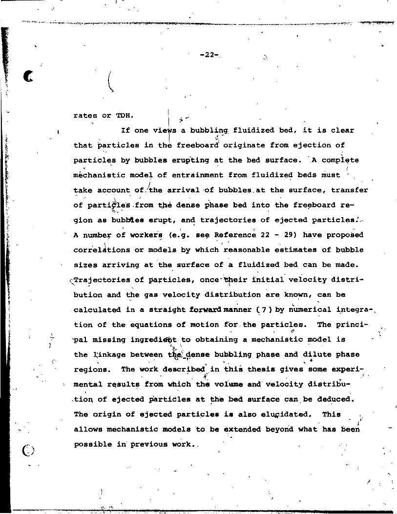
rates or TDH. \ ....
" If one viets : bubbl~:q fluidized bed. it ia clear
that particles in the freeboard originate from ejection of \
particles by bubbles eruP'tinq at the bed surface. . A compl~te , '" 1
méchanistic mode~ of entrainment from fluidized beds must ' ,
take account Of/the arrival'of bubbles.at the ~urfa.ce, trans'fer ,~ ~ "
\ .. of partifle'S .from t,l1é dense phase bed into the fre!!board re-
,t.. . ,
g10n as bubl:4es erupt, an,! trajectories of ejected particles:.,. 1 0 .. ,
A number of worker's (e.q_ se~ Reference 22 - 29) ha,ve proposed , .-l, ..
corr'elzttions or models by which reasonable estimates of bubble
sizes arriving at 'the surface of a fluidized bed can be made. , ' '
~Tra?ectories of ~~;'ticles, once"'~eir il)itial velocity distri-"
bution and the gas velocity distribution are known, can be , . • k
calculated in a straiqht forwa:r:d manner (7 ) by numeriaal iJltegra-,
tion of the equations of motion for. the particles. The princi-
" 'pal missing ingredi~t to obtaining a mechanistic model is L \ ' ,
the ~inkage between t~~~~en8e bubblinq phase and d~lute phase , .
ragions. The work descr~be~:(in this thesis qives some experi-~.. J' j. •
mental r~sult~ from which' the volume and'velo~ity distribu-
.tio~ of ejected partieles at the bed surface can.be deduced. , This t The orig1n of ejected part1~les is also elqçidated.
~.
. ; allows mechanistic models 'ta be extended beyond what has been
possible in' previous wark •. .' ,
, )
•
1
, ,
'.
m .
•
c
t-
" or J
i ~,
,1 li-.::
~., '\, (
}, ~
~ f
\e.- .
o
.. CHAPTER 2
ORIGIN OF PARTICLES'THROWN UP INTO THE FREE~PARD 'REGIO~ ; < y
1 2 ~,l. Introduction \
the low~r part of a bUbble[iS actually concave,
not circular (20) or spherical (3D) As is often assumed,
e.9: b; pavid!'On . (3 Q; . A • W~k~ _ ·.f'O""'S i behind the bubble, as
For spheridâ~,-cap bubbles in li~id!il, tr~nsportlnq solid 0
part~cles wi~h the bubbl~. A:. weàk v~rtex syètem a'ccurs' in,
~e wake and some packets of par icl s a~e shed gurinq
are of key importance 1
in solide mixinq process~s in fIu"di ed beds.
As bubbles burst at the be surface particles"are"
ejected into the freeboard region.· here has been some
debate in the"literature reqardinb W ether theSe particles
come 'frbm patti~les carried. up Wi~h wake,,, which are 1
more repr$sentative of the ôv~ra]~ , .
of· bed ma-
~eria1, or/from tbe c011apsinq do~e t the surface of the , 1; . ~
bed, whidh are known to be rich in 1 ght or fine fractions ,
of the bed (31). Fines may' a1so 1ea4 e the bed surface in the
absence of'. ~b!>~e8 due ta ~e hi~h d~a.9' ï.or,c~ thêre (3'2).. ..
Ih this c~pter· experlments are presented which o
help to give a c1ear-cut idea of the oriqin of ,ejected ..
,
> .:1·, < •• ~.~.~~~~ ... ~\,_.,~:, •
5 l

-, -
. '" ;,
,.,. '"
.r~ --.,
e,
. , ,~
o· l
0'
partieles.< It,is shown tha~ ejected partie1es oiiqinate.
primari1y trom the wake f ;:-:-
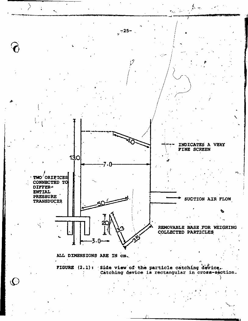
2.2. Partie le Catching
. . ~
of e:L0ng bubbles.
Déviee . ,
, A ,-,eatching deviee ft • was li<
c1es &ject~ into the freeboard.
designed to capt-gre-.parti-
This was constructed from , , ,.. 1 ~
a 24 gauge st'ain~S's steel sheoaet, wi th one; facepJ!la'cde of _____ r
p1èx'1g1ass to allow the performance of the assemb1y and ,the' y .-
amount of col1ected solid$ to be observed. A ·line diàgram ~ ,
r_ of the devt6e is shown in F'igure (2~ 1». , The bottom of the
. . , --deviee "18 r~ovab1é so that the n~er of co1i~cted partic1es "~ l, , '. _
can readil~,be weigh&a. Pivots are inc1uded tQ a1l9w.both 0
... '... _j~ \ f 7~ the 81it width and''th,_ angle ot the deflectin~ baffle to"be
• , " < * ('t adjusted. There are two out lets from the deyice, both
(
covered by fine-mesh scr_ens to prevent en~ained particles f ~ ~
from escaping. One of these ou~lets can be eonnected to a f • _
.. ' 't',' source ,.~ Naçû~ to permi ~ isokinetic samp~lng, as determinêd
by measuring.the pressur~ differenee betw~en two4 screen-, '
covered,orifices, each 0.5 ~m internal d~ametèr, one inside
\
\
•
an~ one DUt8idi ~he i~t sli~ at the bOttom,of the device. • •
.." Th~ Bressure differenc& \as measured using a sensi ti ve press~re ,
'.
J
transducer (MKS Baratron type 77). The catching d~vice was , ,
.c1amped tightly to a .rigid support which could be',mQved ve~i-
ca11'y or .horizonta11y ta Posi~'ion the .slit at t~e d~'~ired 6 "'"
~ o
position in the freeboard.
\'
\ \ ..
4
> .' ,
~~'1""""'~""""",,-_m_,"_'_'''''~_'' __ M __ ' ___ .. _11' ;_, """il","' "A.""'*";_~*,""_4.'"'t __ L""!SUC ..... _________ ... ........: ......... ! U,;&UJI.
, . TWOJORI~ICES ,l CONNECTED T
OIFFER-i EN'l'lAL PRESsutœ TRANSDUCE~
1 0 "'---7·
"
...--3.0--
-:-25-)'-
1
,
. \ .
- ,
I~ .
<
. ,
J.-~- INDlCA~S A Vl!tRY \ - FINE SClŒEN
1- , ~ 1
. .
--.~ SUCTION A:tl~' FLOW
. :
'\
REMOVABLE BASE.FOR WÉIGHING COLLECTEO l'ARTICLES ' , -
ALts DIMENSIONS ARE IN cm., ft> ,
FIGURE (2.1) J 'Side view' of' the ,partiele c~tch!nq d~i'C~ '-'Catchinq d~vice i8 rectangular in croBs-s~etion.
" ' .. '1 '" 1 \
, . "
l ,
/'
, 0
, /', , 'f
7 fl
J
Jl~!j
• c
i
•
-26-
) In the next section performance tests of this
~ catchinq device are discussed • .,.
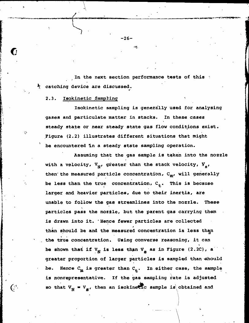
2.3. Isokinetic Samp!ing
Isokinetic sampling is generally used for analysing
qases and particulate matter in stacks. In these cases
steady sta~e or near steady state gas flow condit}ons existe
,Figure (2.2) illustrates different situations that might
be encountered ~n a steady state samplinq operation.
Assuming that the gas sample is t~ken into the nozzle
with a velocity, VN, greater than the stack velocity, Ys'
then" the measured particle concentration, Cm' will generally
he less than the true coneentration, Ct. This is because
larger and heavier particles, due to their inertia, are
unable to follow the q8S streamlines into the nozzle. These ')
particles pasl the nozile, but the parent gas carrying them
is drawn into it. "Bence fewer particles are collected , ~
than s,hould he and the measured concentration is Iess th~n ç •
the t~u~ concentration. Using converse reasoning, it can
he shown that if YN is less th~n Vs as in Figure (2.2C), a"
qreater proportion of larqer particles is sampled than ~hou1d
he. Bence c~ is greater than Ct. In,either case, the sampl~
is nonrepresentative. If the qas samplinq ~ate ls adjusted
so ~hat VN - Vs' then an isokinA-c sample is\obtained and
\ )
\ t.

L ',;
!'I ~,
,;,.
:<
~I '\' ~, ...
'"
• . " tt·. r~ f,. ft
,..,
~
!O ~,
1
-------
=, .. PI"" • '" ._. ~._-.->-"';i42 2 . i _ pa & 42 ; il Z l li,.. » . .' ~--''''.'''-. '.,", ,
>
r",
~
-
! 1
"
(a)
-----------
---------
1 1 VN
ft t fi Vs
v > V N, \"s
.Cm <~
. "
""
S~ple is not representative due >to curvabure of gas streamlines.
Particles deviate from streamlines due te their inerti~
-~-
>1-
(b)
l VN
Vs V = V N s
Cm = Ct
10
>
1
~.
Sample is representative
. 'p
1 VN
,~
Vs (c) VN < Vs
Cm > Ct
Sample is not representative
• . ,
d
FIGURE (2.2): Representat.ive and non represent.ative particulate sampling conditions.
' • .,;.,..J,-"'h .... .... .I)-...dcor~4 lM St'! ~~ _ ..... ~:Qtx,r*itiistt'f'ât
~
~ 1
t ' ~ ~
1 i

, '
~ .... -;...k"_n~' -, _,._~ ... _~..,...,.,.~_>-~._ ~""''''''''r.~'''-''''''' ~,t~~""""~""*1~~.'!~~ ...... ~ __ ,t'><" __ • __ ,,,~_ ~_~'_~ __ 'rl"_"""' ___ ···":;'N'J ._-<" ,c.~""\'''''~' '1.
c -28-
the sample is representative providing the inner diamete~
of the sampling tube is large with respect to the particle
diameter. Non-isokinetic sampling+causes errors both i~ the i
~
size distribution and mass concentration d'termined. These,
errors oocur primarily for large particles. Very small ones,
e.g. particles le~s than 3 microns in size generally fol~ow'
gas stream lines ~uite accurately and are effectively col1ected
regardl~ss of the sampling rate.
For the cue of bubb1,es bursting at the surface of
a fluidized bed, the process is an unsteady state one. A
"puff" or jet of air is emitted by the bubble as it burstskat
the surface. This puff dissipates as it travels into the , ,
freeboard règion. In the present work, the parti~le catching .
,device had it .. two orifices'connected to the pressure.;transdu-'j - , .. ,. cer, with the pressure difference due. to the bubble bursting
'producing a noticeable deflection on a fast-response voltmeter ,. tlI JI'
" measuring the output from the transducer. ~he catching de\ \ \vice was used to scan a large area above the bursting bubb1e. \
\~pertments to test the performance of the éatch~~g deVice
ere carried out in a cylindrical pyrex col~, ,4.S,·.1 cm ~ \
internal diameter ank 110 cm ta1l equipped witn a p~rfo~ated 4-
plate distributor. Particles used were silica sand having
Pp - 300 microns and Umf - 6.9 cm/s. When the ~ackground gas
• , 0
.,,, " .... " ~~ ....... -#r~".-_ .. '''' ..... ,..-or-.f1>III' ,_ ....... _~""~....-~ __ ~~~""#>l"IMo-1~:n....".,..,., ........... _ ... ~~ .. "'""" ... ...,..".,._ .. """" ....... _ .. ~~_ .. __ .......... ~"""'~"!'e.~""---=_f"",.,!-T''''''''''1~~~'l.-''I"~''.,._.,,-
(:
-29-
flow rate was set at about 1.1' x Umf , the pressure differen~\ . between the two orifices, inside and outside the catching
1
device inlet read from the meter varied be~ween ± 0.00005 am
H20 with the Mean eqUaljto zero. This pressure difference
c'orresponds to a velocity fluctuation of the order of .:t. 9 cm/s,
of the sarne order as the background velocity. In other words,
the pressure drop through the catching device with just the 1
background flow of air (no bubb~es present) ~as tao smalf ta
give a measurable difference in velocity between the inside .. and the outside of the device even with the sensitive transdu-
cer employed. Hence there was no need to apply suction to
maintain isokinetic sampling during steady state operation,
i.e. wh~n °no bubbles were bursting at the, bed surface.
When bubbles were injected and broke thé surface,
there was a deflection of up to 0.0035 cm H20 which corresponds
to' a velocity of the arder of 13 cm/s, of the same order as the
bubble velocity. The sign of this deflection was sometimes "
posi~ive and sometimes negative depending dn the position of the
catching device relative to the bursting bubble. This deflec
tion indicates that particle ejection at the surf~ce is accomp
lished by a "p~ff" .. of air from the bursting bubble. If such a
P~ff is like a jet (3), one mi~t anticipat~ an instanta~eous
velocity profile which would ~e approximately Gaussian sa that
there would be substantial velocity gradient~ leading ta
hig er instantaneous velocities at one of the
'-'---~-""-----. , , ' 1 >\ ,.. r:, \ / '~~. ,
.'-
1 _~~~~ ....... ....tt.tT: .. ~.
l , t
-30-
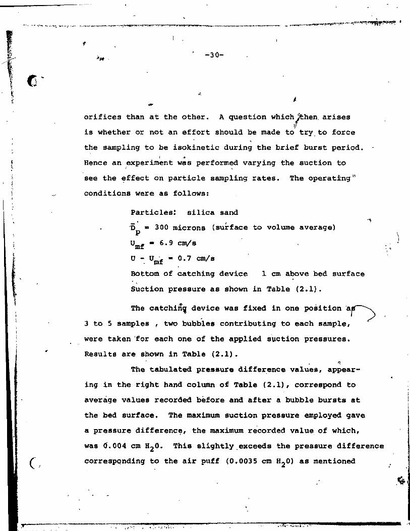
-orifices than at the other. A question Which~hen, arises
is whether or not an effort should be made ta try_ to force
the sampling to ~e isokinetic during the brief burst periode r ,.
Hence an experiment was performed varying the suction to r
see the ~ffect on partie le samp1ing rates. The operat±ng~
conditions were as follows:
Particles! silica sand
-0 - 300 microns (surface to volume average) p
Umf - 6.9 cm/s
u - U· - 0.7 cmls mf
Bottam of catching device 1 cm above bed surface ,
Suction pressure as shown in Table (2.1).
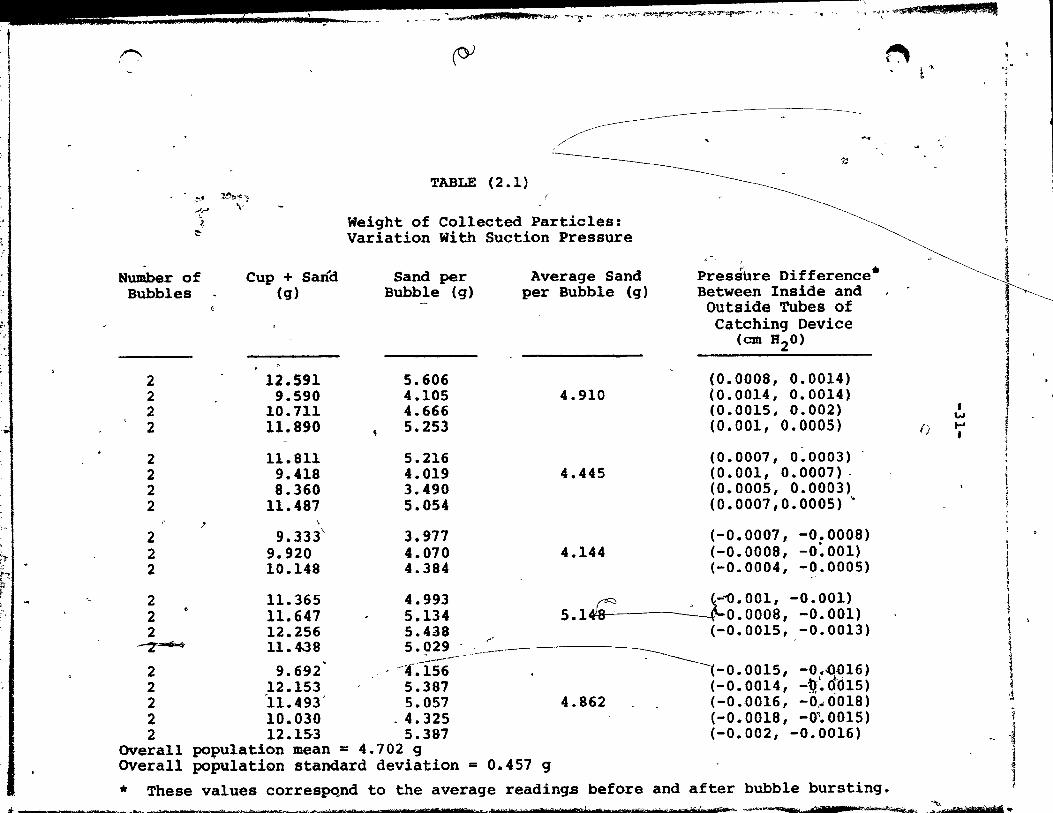
The catchi~~ de~ice was fixed in one position ar--:> 3 to 5 samples , two bubbles contributing to each sample,
were taken 'for each one of the app1ied suc tian pressures.
Results are shawn in Table (2.1). '\\
The tabulated pressure differ,ence values, appear-
ing in the right hand column of Table (2.1), correspond ta
average values recorded before and after a bubble bursts at
the bed surface. The maximum suction pressure employed gave
a pressure differenc~, the maximum re'corded value, of which,
was Ô.004 cm 820. This slightly.exceeds the pressure difference
correspQnding to the air puff (0.0035 cm H20) as mentioned
) .. i
:
.~
_ ,!!.t .. fUt. . __ ~, -. .--,oUDH.) .0'_.- ~",~- ,~<-"'-"'~~-'4""","""~"'" -0, - -f '.4»"'$ .... Ma! $" 1 .' ,- ,~ ", . ~ ~, -
1 1
';
,.-...., . . (Y
.;:
TABLE (2.1) ~., ~~1 ..".,J
\.
~ :-:
Weight of Co11ected Partic1es: Variation With Suction Pressure
< " ,
Humber of Bubb1es
Cup + Sari'd (g)
Sand per Bubb1e (g)
Average Sand per Bubb1e (g)
Presshre Difference· Between Inside and
12.591 5.606 9.590 4.105
10.711 4.666 Il.890 5.253
11.811 5.216 9.418 4.019 8.360 3.490
11.487 5.054 -' \
9.333\ 3.977 9.920 4.070 10.148 4.384
11.365 4.993 11.647 5.134 12.256 5.438 11.438 5.Q29
- --~---_ ...
9.692 _ - -~ .156 12.153 5.387 "!1.493' 5.057 10.030 - 4.325 12.1S3 5.387
povu1ation mean = 4.702 9 population standard deviation
/
== 0.457 9
4.910
4.445
4.144
Outside Tubes of Catching Deviee
(cm B 20)
(0.0008, 0.0014) (0.0014, 0.0014) (0.0015, 0.002) (0.001, 0.0005)
(0.0007, 0.0003) (0.001, 0.0007)(0.0005, 0.0003) (0.0007,0.0005) "
(-0.0007, -0.0008) (-0.0008, -0:001) (-0.0004, -0.0005)
r= " ~-1).001, -0.001) 5.1~0.0008t -0.001)
(-0.0015, -0.0013)
4.862
-0.0015, -0.G016) (-0.0014, -P'~Œd15) (-0.0016, -0~0018) (-0.0018, -0~0015) (-0.002, -0.0016)
~
* These values correspqnd to the average readings before and after bubb1e bursting.
l ..
f)
1 w ... 1
.,
j l i i ! \
l 1 1
1 f J . ,
\
1 i
1 t '
1 'l
* 4 j
1 1
.. ____ ~ .... __ .. ~ _ .•• ~~-....tb..-.i"""-~~ ___ .......... _.~.-.-..... ~~,-", UètMt ms .•. ",,-.. ~.%AIJ5.> • .. .... : M. h1t t"tidlra.MillAM ftbshrr .::s"hÙ $f-~'" ~~-~, aM n~~",- ~.H :e:ère nda}tu1ft' ...
.

.'
.,
.-f ,
•
(l
-32-
\ above. The suction pump 'employéd limited the fe "Of higher "
suction pressu~~. St~tistica1 tests were performed using
the data of Table (2.1) whicQ~help to show bhat there was .- -noAsignificapt difference betw+en the average weights sampled
at live deffer~nt suction rates with a confidence revel of
95' (see Appendix: (; ). Bence ~e may conclude, qualitatively i
at 1east, that suction has a n~gligible effect on sampling
rates for the above conditions. Since the suction applied
was far in excess of that requireâ to achieve isokinetic ,
conditions correaponding to background (ateady state) condi
tions, it appears that no special attention is required ~o
achieve isok~etic sampling for the background conditions
of this work.
It may be concluded that isoklnetic sampling was
not necessary during the brief burst period for the fol1owing
reasons:
(a,) .\
The non-uniform instantaneous velocity profile in the
g~S when the bubble bursts ia a phenomena natu~ally associa-
ted with the burat!ng proceas.' Tc suppress it wou1d interfere «
with the process un?er investigation.
. (b) It i~ certainly ~ossible that there i8 a time 1ag between
the arriva1 of the maximum in the gas ve1oc,ity and the arriva1
of the majority of particles. Jn that case, one would over-. \ compensate by~roviding ~ufficient suction (or blowing) s6 that
":>
" 11 ë s 77' nr.
}I
" )'. j
(-'
-33-
r
... the peak dynamic pressure difference corresponded to zero.
2. 4 • EXPERIMENTAL
2.4.1. §quipment
Experiments were carried ou~ in a pyrex column
of 10.8 cm diameter, 150 cm high. Operation was semi
batchwise with no solid recycling. The grid consisted of
two 0.32 cm thick porous steel plates supp~rted on a
mesh. The f1uidizinq '9as was air whose f1,9w rate was mea
sured with a calibrated rotameter. The solids used for this
'. set of experiments wer~ si11ca' partic1es. "Flint silica
cparse type"~ h~ving a mean surface to volume diameter of
"
0.0358 cm and a measured minimum fluidizing velocity of 9.3 cm/s:
t)
The particle ~atching device shown in Figure (2.1) -[/
was mounted in such a way that the slit opening (3.4 x 4.9 crnY
was 3 cm- above the bed surface with the centre of the slit
on the axis of the bed. ~The copper bubble injection tube,
0.5 cm "i.d., was immersed in the bed, 26 cm below the surface.
This tube was fixed 50 that bubb1e~were injected at the bed
axis. Reproducible bubble vol~eB were provided by connecting
a solenoid valve to a timing device which a1lowed the time t
between injections and the time of openinq ,to be adjusted to
desired levels. The volum~ of qas injected was meas~red by
1 1
~( 1
--------~------------_,_';_' --------- '

.. "
1 l , }
('
,
/'
..... ,
having a second solenoid upstream of the first with a
'~oir of known volume in between, connec~ed to a
pressure gauge.
2.4.2. Calculation of Bubble Diameter
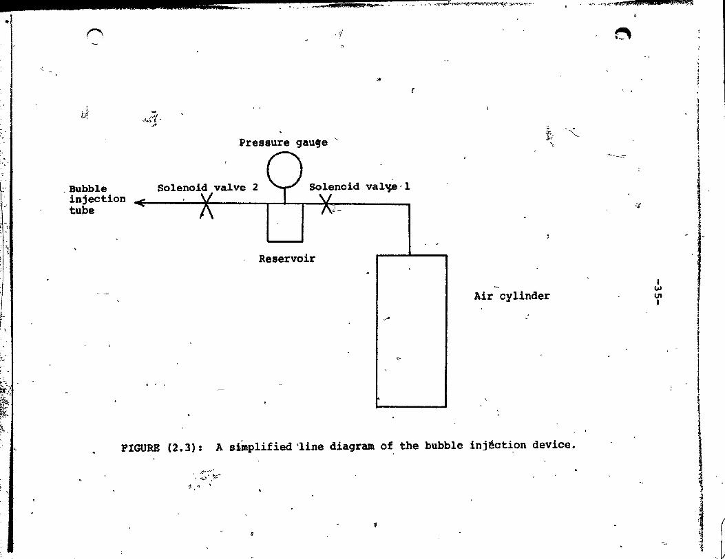
Figure (2.3) shows a simp1ified 1ine diagram
of the bubb1e injection device. The bubble size was set
by adjusting the t~~ing of the solenoid or the
pressure in the reservoir,or both. So1enoid valve 1 was
'\.opened to pressurise the reservoir to the required pressure
and 'was then c1osed. 'So1enoid valve 2 was then opèned
for a short preset time, adjusted by a precision timer
device, to depressurise the reservoir. A bubb1e then forms
at the tip of the copper tube 10wered in the bed. The size
of the bubb1e at the position of injection is ca1cu1ated as
shown in the' -'~11owing examp1e:
(1) Ca1culate the number of moles of air injected into
a bubb1e:
Pressure drop' read from pressur~ gauge - 246.2 cm H20 , \/
Average diameter of the reservoir - 10.8 cm
Height of reservoir ~ 15.2 cm
~sing the equation of state: 1.\
\.< PV • Z~T where the compressibi1ity fa~tor Z is tûken to be unit y
for air under t~e experimental conditions.
_ i j il JE il 22 Lib 2;;;; ' .... ~_dAi; .~.I.Ji_"· . - .... u"-"':::;;;;:;;;:--'~~"'3',"""~'r'
•
"
-.>
. '
tt 1 ~I •
:1,1:
"(~~
~.~ ~~.
J:o;.~~
Kt;. ~ ..
<.
(';
~
. Bubble injection tu~e
''1
>1.;1 '
Pressure gau~e "
Solenoid valve 2
i--
Reservoir
-*
~ .. ~ "
val~-l
Air cylinder
~ ..
'"
FIGURE (2.3): A stmplified 'Iine diagram of the bubble injêction device.
............ ~, +' ... )" ,~;'"
-j .....
~
B
.... "~ ~""""i~"'~.'&C lR45Jô9%:
~
- ........... --:=--
.... -..
1 W Ut 1
1
~
t t i
1
! 1
1 1
1
1
1 j ( l l
(j
,.
- , f
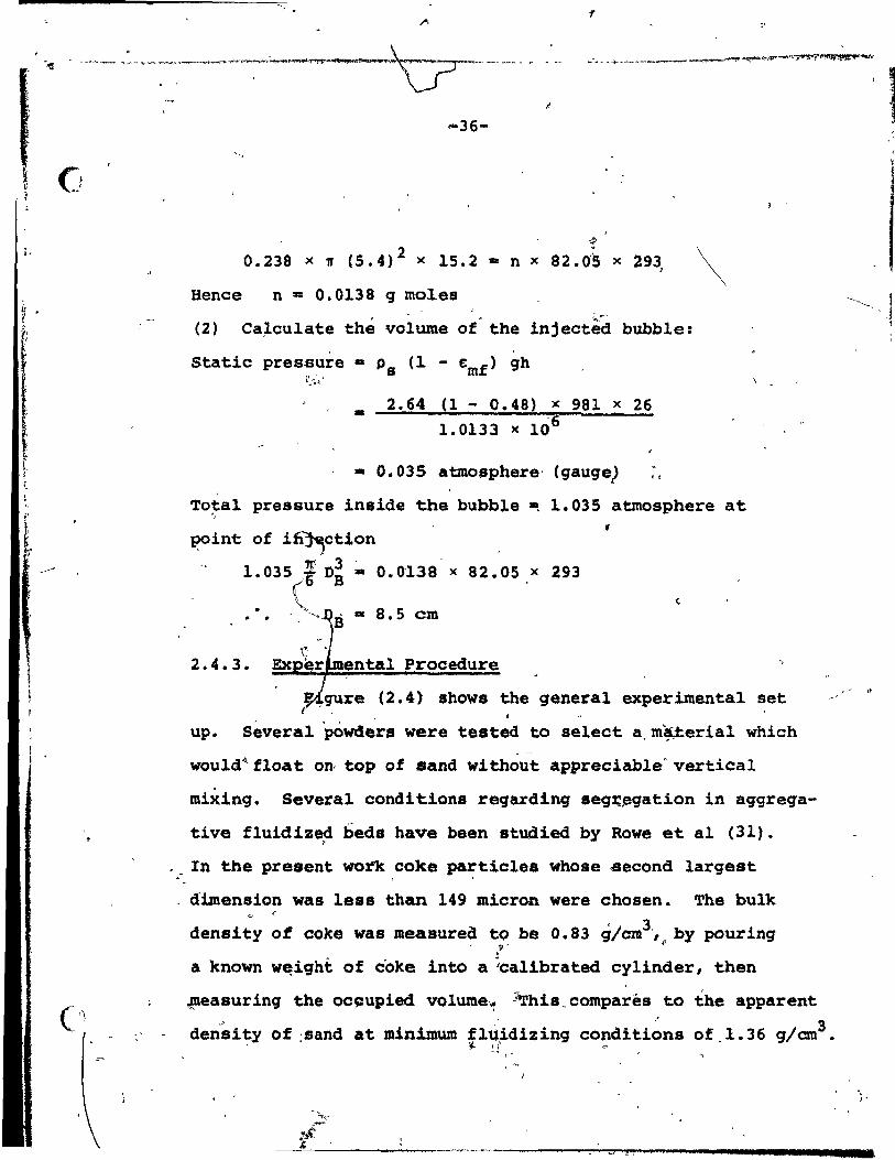
-36-
0.238 x 'If (5.4)2 x 15.2 - nx 82.0"5 x 293 )
Bence n - 0.0138 9 moles
(2) Ca~culate thé volume of the inject~ bubb1e:
Static pressure
- 2.64 (1 - 0.48) x 981 x 26
1. 0133 x 106
- 0.035 atmosphere' (gauge) .,
\
Total pressure inside the bubble ~ 1.035 atmosphere at .. point of i~ction
1.035 -i D~ ,. 0.0'138 x 82.05 x 293 ( •• ~ !III 8.5 cm
2.4.3. Procedure
l -
t ,~re (2.4) shows the general experimental set , "
up. Severa1 powders were tested to select a,m~erial which - -
would~float on, top of sand without appreciab1e'vertical
mixing. Several conditions regarding seg~~gation in aggreqa
tive fluidized beds have been studied by Rowe et al (31). ,
", In the present work coke particles whose second 1argest
dimension was 1ess than 149 micron were chosen. The bulk " r
density of coke was measured tQ be 0.83 g/cm3',~by pouring , S"
a known w~iqht of coke into a ~a1ibrated cylinder, then ,
~easuring the oc~upied volume~ ;~his.compares to the apparent .'
densi~y of :sand at minimum flUidizing conditions of.l.36 g/cm3 • 1/. ~f
,..,' i J
1
~"',l
. J'
•
1

]
~
".
" 1
" r. "\
I~
!: 1 ~ ;.
,r"\., .
r
A Air cylinder
8 Fluidized bec!
0 Distributor
M Manometer 1
p j ~
Pressure gauge
R Rotameter f. .
S . ~i}bbid valve
T
V
•
''ro air supply
I~jection tube • ~o
.Valve· .. t"~~.,. t;
~ .,
j
-.
1. 'Il ..... ~, ...
R M --
\
"
1)
, ' ,.\
'.
8
-T ~~ .. ,.. "Il
..).; .. ..-
\\
fi'
, \
.. --- 0 -\-1
-FIGURE (2.4): Line diagram o,f the general eXperimental setup.
f
A
;.
1 w -..J ,
i. t 1 1, 1
,.
; , '. ',' " '.' .. if. . " pp l , ,~ r • k?_~ _____ , ~~_~_,-"_'____ .;&,_.; _.... .. am T7 TI # ..... '1 r'Swes n 'tÎ'lifo17f:sm?%" rtS h~"'''''-'~df l> ....... "'~s-fbutm 7 ,_
"

\'
Cl 'J ..
, .
( ,~"
,J
.... __ T
•
-38-
"
The coke part~clea had the advantage that they segregate
readi~y to form a pure sur~ace 'la~r at t~e low o~erating •
superficial air veloeity used (9.8 cm/s) and their 'black \
,~
colour allowed this segregat'iqn to be verified readily. '. '
This choiee of sup,rfieial air velocity,also minimised
attrition of coke particles and redueed elutriation of 1 .
these ligpt and small coke particles, relativè to sand
p~rtieles~ ~
[ 'l'he total ,weight of sand poured ,into the bed . ... -" , , - ri, ,
.was lO.21,kg. 'A thin, layer of coke par~icles (init~ally
5.5 g) was carefu,liy sprinkled.l,over the bed s1,lrfaee and " -. . ' /
t:he bed wa,. fluid~zed air veloei ty o'f· 9. 8 omIs for .
about half an hour. little mixing,o~ c~ke and, sand t'
was observed. bùbbles w~e injected into the bed
~nd s~les vere collected in the catcping'device, analysis ~ . i , . ,
.~ein9 ,:aar~ied out ,~:~e~ ,three bÜ~ble, eruptiQns. ,~\The. ~~~-
ness of the coke ,layer'vas increased ~or each run by addi~ . . '
,~, 1.
more coke, then !epeating the sampling 'procedure outline~
above.
2.4~4. "
~~ , ,~ //
separa~i~n of Coke From Sand in Anaiysing C611ected Samples
i
'l'he difference in Specifie gravit y between,coke
(1.9) and sand (2.,64) provided a method of gravity,separ,- .,,' ! ' , " ,
tion.' ·An appropriate liquid, l, i - dibromo-et~anel was .Iused +- '. ~
o • ..
~.~".': ,7' •. !t''V- 4 .'". "
l'
..
j
-'Of .. "
, ,
"
o arll-'· ..... ~ ... ~f'<Pf~"I~'lir.!W ....... A filA tt.$. A4tcatl!oL.ilbSi ~ . ~~' ___ '_'. _______ """""""'7?'!~~'!!!!t
...
,
..
-39-
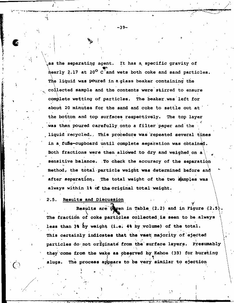
\ 4..as the separatil1g agent. It has a. specifie gravit y of
"<,
~earlY 2.17 at 200 c~nd wets both coke and sand particles.
TlliqUid was poured in a ql~ss beaker containing the
co lected sample and the'contents were'stirred to ensure \
c~m~lete wettinq of particles. The beaker,was'left for
abo~t 20 minutes for the sand and coke to settle out at' '
the bottom and top surfaces re$pectively. The top layer , if
, '
es liquid recycled., This proCedure was 'repeated several t . ,
in a, fuSe-cupboard until complete separation was obtain
,<,\ Both fraction~ w~ré then. allowed '.to dry and wei~hed. on a
sensitive balance. ,To check the accuracy of the , ,
method, the total-particle weight was determined before and , '
b ~ ,
aftet' separatlo~. ,The tota.l weight of the two *4amples waS ~
always w!thin l' Cf the original total' weiqht.
2'.5. Re,aul ta and Oiscuss,ion l ' , ' ·,t , Rea~lt. arê-~n in Table (2.2) and in Figure
The fractidn of coke parti,eles co-llected. ia seen to be, alwa.ys
less than ~, hy wèigh~ (i.e~ 4' by ,volume) of the total. , ,
v '1 ,--
This certainly indiclltes that the và .. ~ majority of'éj~cted • , 0
particles do-not or}ginate from the' surface layera. - , ~ . "
,
P;re.wnably
they"come trom the ~ak~ as observed bN K~e (33) for bursting v (/ ." .. 1 • ., . C'.) ç" slugs. Thè procetJs a~p=,!~r8 to be ~ery aimUar t~ ejection
, , , .
, ,
.'

, ,
~ ;,
1 t
1 1
\ r
C
" J 1 \
\ \ \
\
.
-40-
r
TABLE (2.2)
Origin of Particles Experimental Results
J Sample . Weight of Thickness of Weight of
Coke Layer Coke ~ayer Coke (g) at Incipient Col1ected
~ Conditions (g) (cm) Per Bubb1e
:1
1 5.5 0.07 0.017
2 6.5 0.0 6 0.065
3 8.0 o. OS 0.108
4 ·'r 9.5 0.125 0.086
5 11. 0 ~ 0.147 0.101 .riJ
6 12.5 0.164 \ , 0.143; 1 1
fI \:- 7 15.0 0.197 0.128 ; 1 1
& i ~~~~
~ .. ~- ,) ,/ /,
/~~ 1
~~
1 •
l J
Weig,ht of Weight Frac- 1 Sand, tion of Coke 1
Co11ected Co11ected l (g) ,
Per Bubb1e Per Bubb1e
7.535 0.23
6.286 1.02 1
5.697 1 '.1.86
4.264 .1.97
4.608 2.14
5.488 2.54
, 4.234 2.92
\,
"

..
3.0
o o
,1
-41-,..
. \
e'
• 1 • 1 • 1 l '
• • r'
•
• 0.1 0.2
TBIClCNBSS OF COD LAYER AT INCIPIENT CONDITIONS (cm)
FIGURE (2.5): ,eight fraction of surface p rticles captured as function of tracer layer th! kness. "
"
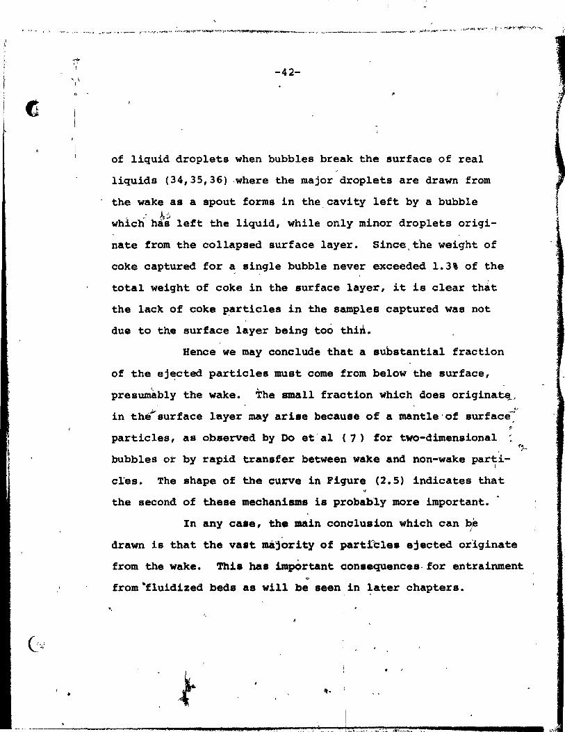
., ....... M ,~ ... _ .......... _""_"-'~""'- ~~~...,~ ... , ... ",",,""'" ,_~ ..... ~ .. -,..""''''l<_. _ _. .. _ .. il..,.'''''."..~'-....... - ...... -~ ... -_~ ~ ..... ____ ...,. ___ ........ ..,..".+o ... ~, ~ ",.J.J~"....,.T-- ... - "".<oI-tI<4t .... ,.e .. ,." j' ~~"..,.y~..,,~,.((..,~
-" 1
"
•
-42-
of liquid drop lets when bubbles break the surface of real
liquids (34,35,36) ,where the major droplets are drawn from
the wake as a spout forms in the,cavity left by a bubble r .: b-~ ~.
which has left the liquid, while only m~nor droplets or1gi-
na te from the collapsed surface layer. Since,the weight of
coke captured for ~ single bubble never exceeded 1.3\ of the 1
total weight of coke in the surface layer, it is clear that
the lack of coke ~articles in the samples captured was not
due to the surface layer béing too thi~.
Hence we may conclude that a substantial fraction
of the ej~cted particles must come from below the surface,
presumàbly the wake. The small fraction which 40es originatq,
in the(surface layer may ariae because of a mantle'of surface~
particles, as observed by Do et' al (1) for two-dimensional :
bubbles or by rapid transfer between waxe and non-wake parti-1
cres. The shape of the curve in Figure (2.5) indicates that
the second of these mechanisms is probably more important.
In any case, the main conclusion which can bp
-1". ,t-
drawn is that the vast majority of partrcles ejected orlginate
from the wake. This bas impOrtant consequences-for entrainment
from 4fluidized beds as will be seen in later chapters.
4t •
1 ---=----------____ 1 ... '_ .• u-.-....... ~~~.:_tl"::"'~.,'l~._ .. ':'!:" .. ~,:::_: .. ,"::. .. ~·?.!r.'.';;l~;:~.""~ ... ~ .. ~"~. - ... ---____ 1 Lv"
t
(-, JI
1 l' /
1 1 1
-43-
'.
CHAPTER 3
VOLUME OF EJECTED PARTICLES
3 • 1. XPERlMENTAL
3.1.1. Equipment and Materials
Experiments were carried out in a pyrex column ,
of 45.7 cm i.d., 110 cm high, with no solids being recycled.
id wal~ a perforated plate. Air was used as the fluid-1
ga~ ~hile extra-dry compressed air was used to in je ct
the bed. Three different types of
silica sand, bal10tini and FeC catalyst.
\
tics of these particles are presented in Table (3.1).
were
drop
e fluidizing velocities at incipient conditions
in the &onventi9nal way by plotting bed pressure
superficial gas velocity for both increasing
and ecre' sing gas Iflows, as shown in" Figure (3.1). i'he inter
cept of t e two straight line segments give a value for Umf.
The abui
two nt'er
~,' usi
of Umf are averages, each obtained from
The void fraction at Umf,was calcu1ated
Papparent· Ps {l (3.1)
The ty,of the solids, Ps ' was measured u~ing a Pyç,nometer
and , while the apparent density was méasured by measur-, ~
ing the olume of a g~ven,weight of particles in a bed in-
cipientl fluidized.
. ..
R1 Il T
,. ) t
f
. '.

"
, 1
'1
~ è
~ ~.
~
r~
"
.'
.:..:-, 3'~
G ,I!!; ",
i~
~.
~ :"-'"
TABLE (3.1) : Materia1 Properties
Material O.S. Sieve Opening Rang~ Weight' Total Weight Pp (g/cc) (microns) (kg)
s
-"11'.1'\.1' 9 Si1ica ' -40+50 -420+297 ~ '~', ~ft ~ ~4 Sand
-50+70 -297+210 41 , -70+100 -210+149 31
-100+140 -149+105 14
-:1"0~:200 -105+74 4
-74 1
---------200 )
b
FeC Catalyst'
Ba110tini
-100+140 ,
-140+200
-200+270
-270+400
-400
-50+60
,.-149+105
-i05+74
-74+53
-53+37
-37.
-297+250
' 13.96 45.36 2.0
35.7Et .. 23.20
13.98
13.08
'f> . '100 120.20 2.46
li ,
Emf (cm~~)
0.48 6.9
0.72 0.4
0.45 5.2
~ 8t
~
~)
~
•
...
1 ~ .... 1
/
1
1 ~
,1
.
l J !
1
1 l
~ ~ 4
l ~
1 '~
1 1
" a . 55 $ ~ ??S Hnm ms p' J'''E1_Plilli)' 1" "aM rn_pm .-r'_1F ; 2' _\~ ~"îi'i1t1Jlr,. ' - ..
fi
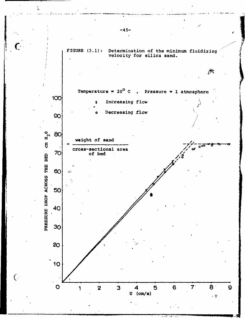
•
100
90
c::> 80 ("101
te
fi
~ 70
/XI
~ 6Q E-t
CIl CIl
i CJ 50 < ~
i Q
~ 40
c ,CIl CIl
m 30
20
<:'
10
C·' Q
-45-" .'
"
//-"" ., FIGURE (3.1): petermination of the minimum fluidizinq // .1
velocity for silica sand. ~
Temperature :II 200 C , Pressure - 1 atmosphere
• Increasinq flow } 0 Decreasinq flow \
/ weiqht of sand
+ -7Ç!-- tt~ lb «* /. / 0.0 cross-sec tional area / or
of bed /, /,: , ,
:.. ~
1 2 3 4 5 6 7' 8' 9 u (cm/a) ,f)
. . ,
($ Gi ;" t" hfJ .. • J; •• ; ,,~~ , , . ..,
\
.>
-46-
Two tubes of different diameter were used to in-
ject bubbles into tneJ~f1uidized bed under the following
conditions:
TÙbe Oiameter 1. d. (cm)
0.50
0.75
-.
Bubble Oiameter rem)
<10
<15
3.1.2. Procedure
Positio~ of Injection Tube
Below Bed Surface (cm)
30
45
Experiments were conducted by injecting single
bubbles into beds fluidized auch that U.l.05 Umf • This
background flow rate'waa chosen i~~ccordance with X-ray
measurements of Rowé and' Partridq~ (38) discussed in Sec-. ~
tion (4.2). For operatIon at U - 1.05 Umf , the!e was little "--"" ,
problem of injected bubbles breaking up ot deviatinq signi-
ficantly from the axis of the column. '
The slit of the catchinq device was positioned 0.5 cm
above the bed surface 80 that particles had to travel a
distance of about 4.5~ or more in order to be captured.
For an initial vertical par~icle velocity of the same order
as the bubble velocity,the trajectory model (see Ch~pter, 4) _L
, ,
assures that aIL particles under investigation would be able
to reach this heiqht and., thus wou Id he collected. Prior to
injection of bubbles, the bed was fluidi~ed vi90rously\fo.~ l'r
~

?.. ~ Q'?
, ..
:J ~ -,.'.r .... .."'.,,~~·~'",po<'~~ ... ---~~~~~<>c~ .... -"'_ ..... _ . .,. ___ '"-.,, • ... ..", .... __ ~_ ..... ~ ~_~ ................... ..- , ....... ''l''''Il'. ...
...
-47-
30 minutes to minimize segregation effects. The catching D
device was placed at different radial positions and two·'
to five sarnples weighed at each of thesépositibns. Each
sarnple in·turn represented two to ten bubbles, the larger . number further from the axis of the CQlumn where fewer
partiales were caught for each bubble. The bubble size was
set for each run by adjusting the time of opening of the
solenoid or the pressure in the reservoir or both (see
Chapter 2). Figure (3.2) shows a geometrical construction ,
of a typiaal area fram which ejected particles were colleeted.
Representative sample results of weiçht of particles collected
for various bubble diameters and for the' t~ee different ,
types of particles are shown in appendices (Ha) to (Hf). To
aceount for the blockeà area of the slit due to'the presence
of the 0.5 cm i.d. tube, the total area of which represents
8' of the total 81it area (3 x 4~~ ~ in cross section),
the total weiqht of partieles aauqht br the catchinq device
must be mult:.iplied by a .factor of l :08 •
CinE photographs were taken from9above of bubb1es
breakinq the surface pf the bed. The mean diameter, Df' of
the eruption dome was then measured from;
N j!lDij 1/3 ~
Df • 1 1 (3.2) N
where N la the total number \
of observ~tions. \
~
Sb ,

$,
-48-
" . . ' .
.
24 20 ~ 21 17 , . -
1
23 19 . 1 16
Id" .~2, 18 2 15 1 J ~ 1 • 1 -
.' ,
. 13 4 3 14
Ij
"
/
12 5 6 11 J , ,.
, , ~
. 10 7 8 9
,
FIGURE (3.2): Geometrical construction of a ty'pical area trom which ejected particles were collected. The numbera here are uaed, for identification purposes.only.
,
,
,
.

.' ,
".
•
o
•
j' " " 1
-49-'-
3.2. Frontal Bubble Diameter
Followinq Harrison and LeungO(39) we expect
Of - XVl/3 (3.3)
where K is a constant. By the method of least-squares
Kwas found to be 1.75 for sand. Henee we can write: •
sinee v·· + 0' (3.4)
(3.5)
The constant of proportionality ls near1y 9%
lower than the corresponding value obtained by Harri,on
and Leung ,(-1.55). ft
The corresponding equations found for FCC are:
Of - 1. 10 v1/3
or Of - 0.89 0, (3.6)
(3.7)
The .+esults for both types of partie1es are shown
in Figure (3.3).
3.3. Normal1zed Volume~f Ejected Particles a8 a Function of Bubble Diameter
The volume of ejected.part1e1es was ca1culated by
dividinq the weight of ejected particles (sUmmed over the
entire cross-section) by ~e apparent density of solid par-. ,
7
j
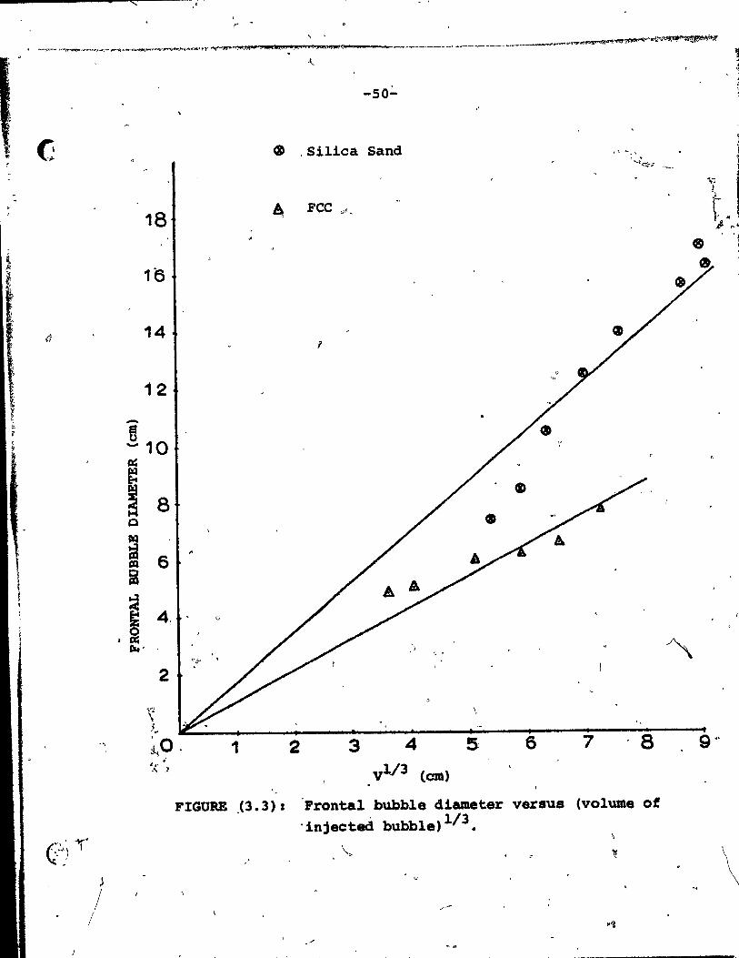
i ~' 1
1. " ~ , j
(]
~
/ /
• sc:::: "
, ..
-50:"
~ ,Silica Sand
18 ~ FCC "t,
1e
14 r
12
-!10 ~
~ 8 Cl GD lk1
iiI " III 6 i
~ 4, G
, fi 1lI4' " .
~,l" ,
2
\ \,
'i -~
~~O . 1 2 3 4 5 '"
.. _, :1
FIGURE (3.3):
vl / 3 (cm)
'Frontal bubble diameter "injected bubble)l/3.
~
"
~
f>
"
6 7 '8
versus (volume of
\

! , 1 •
• 'r
, ~'fI'~'-"""t-~1I"""'~_t~ ____ ~O!t~~' "4'l!lap • .,.,,~!~""""'._""'''''''' 1iA_i1 ___ r' ______ ......... _,_~.~N'I'_: .. ~~ l~
G
. . ,
/ 1.
-51-
ticles: 'The results, nor.màlfzed with to the volume
of the injee~ed,gas, a~hown in Figure 3.4} for si1ica
sand, ballotini 'and ckcking c~talyst parti~les. !Erro~ bars~ are shown on the figure. It is seen th~ the normal~zed .. '---
volume of ejeet~ partieles inereases approximAtely,linearly , \ ~
with bub91e volume for the range of siz~s studied in uhe
present w6rk. ,The least'squares fits for the three types'
of partieles ar.e as follows: "J "
Silie& sand ~ • 0.0142 DB - 0.091 (6. 4s.DB'14. 5) {3.8)
Ballotini ~ . 0.0209 Os - 0.123 (6. 8~B~14 ~,~) (3.9)
Fee ~ . 0.0258 DB -~0.014 (3 .-8s.Dss'9. 0) (3.10)
" where t is the volume of partieles eaptured divided by the
volume of gas inj~eted to fo~ th~,bubble and DB ls in units Q
of eentimetres. In all 'three eaaes the in~ereept at Da • 0 ("0-- , le neg&tive, suggeàting that ,very small bubblea May ejeet
a~negligible volume 'of partieles. The inerease in relative
volume of ej~eted partieles vith inereaae ~n bubble aize • ' l ' •
" probably results fr~ the ineteaaing'wake fraction (deereas- . . , \. " ,,' . \ j ing included '~ngle) 'whieb oeeurs aa bubble. increaàe in '-
• • 1
size (38,40). Averàge value a , of vake ft-action, f:w' obtained
fram X - ray photog:z::.aptùl for .aimilar partieles (38) are ,~+SQ. jj ... \
.' sho.wn in Figure (,3.4). Îl,t is noteworthy'that· rankinq ,4:11e
~ .... f o· .. i
, thiee systems in the order,.of i~ereiaaing, fw gives the same
" ~
-- . , l~

\ ,U' ~ ~ 1 , " \
..... "",.'t''h"l."'". ... I~'"'1t'!~ .... ~.t'fr1 ... '~............,.. .. ,, ..... .. ll .. """'""i!: .............. !t<J_"<1!\'III_. ___ ~ .... ' ____ _ __ ~ _____ ......... ____ .. .,.. ,., ____ ~ ~''Olllfllljpc?J. :"""'. ne" ,et"",,..": ; ...... ___ ~ ... '" iBIl'ftW4 UA." x7.~~2U .. tA5f!~
, L
... -52-" ..
• a
'4D FCC " 035
.\ J'
. Ballotini
\ ...
~ Silica Sand .. .. 1-~ "
., :
f
" 1 o. \1 0
lI.I' q "',
Ba\.oti~i J " ,
.. (Il ')
~ " fw tJ ,~ \)
.t-t \
.....
= ' , 0
\) , O. -.. f...
.1 Q..
Q " ,1 ~ ;-
,~ ~~ 5 "
II -1
)
(l " .,:'
O. J. f. Sand ~ 1 W ... f! . " ~ .... ~~
~ ,-
~ ) " go .. ~Q15 N . ...
! 1 . \).~ /,
" . , .
" QlO ~ 1
~'" .
, , .'t 1 .; --. 1
1 ; ·0
1 l~ ~
" ~ '. i ," a
------... l' 1 .'" , ,. e, \
~ T ! '. 0 2,
" 4 6 - 8. ~ 10 12 ~ '14 16 18 '
BUBBLE DIAMBTBR (~)
func~~ , - ..
1 . rIGUIU!: (3.4), Normalized volume of ,ejected particle~ •• of bubble diameter .. ~
, , ."
l ~ ~. . .... , < .,., 'A.".~:-t-r .. W/(, ~lt_1'Ih.·~ ... :'-.1"."',.'.~ . .,.s!.'l ... L,~ ,u.,' uft:;!:::tI~.'(.~~~ .. :~~ .. ~~Jl,;J"':~'!1.',~. ~;..,.;:'i:;,~.7'." ~ '", ~'" i. ,

, , ( ' .; )
..
-53-
"
l,
as ~anking in order of increasing relative ejection
Further, t is ,always Iess ~~an fw' but app~ars "
, , to approach fw wi th increasing bubble size,. Both of these
~findings are 8gain consistènt ~~th the importance of bubble ...
wakes in.determining partiele ejection in fluidized beds
as discussed in c~aptèr 2. \
3.4. Pa~ticles Ca~ght)lâ, a' Function of Height and Oedueed Velocity Oistribution of Ejected Particles ,
The bal~ot~ni particles were sievea to a narrow
\ .. ~ze range' (:-297 + .·J2~~ lJlI\). The procedurE! of' th~ previous , !: ~..,
section was re~~~1! b~: with a single bubble size and the,
catehing device now scanning the er6~s~sectional ar~a at . . ' , f ", ~ r _?
a series of vertical ~sitions in Qrder tO'give~a profile ," Ci" - ~ ~ !fi ..,,,.,
of the tot~l amount of'solide as a function of heiqht and };
•
~ \
radial position. The,vertical profile is given in Figure (3.5) •
As expected, the 'yolpme o~ solidsfalls off steadily. No . , par,tieles 'were found' above a height of 90 cm above the bed
surface for the conditions studied. Radial profiles are •
shown in Figure' (3.6) for different heights. As expected, 1
the profiles becam~ ,flatter when pro~e~ing avay from tne ~ ë) 1). #
o
position of ejection. The slight asymmetry of ehe profiles ,
,i8 presumably due to injeeted bubbles not rising perfectly
v.~tically'atOng the bed axi~ •.
, . , l
1
~-----------'~'._~_~I~~""""""",,~,,~

1 •
" y
"f.
, , i.
-~ ~ ~,
~ CJ
.1-4
~.
r ~
~ .f 0
PC 1.,
t!) , .... ~
1
o
PIGUU (3.5).
..../' Partiales: Ballotini
'. . \. . \
~
:.
~ ~
, .
·50, . 60' '70 BBIG8'1'~VZ DBD SUlU'ACE (cm) • c
;- ~r .. "tt,
Vertlcal p~ofil. Of;~ticl. voiume. at 41fferent h.iqbt.~ln:th. freeboard.(sampling over entire cro •• - •• cti~n.~ -.ch h8i9h.). 1

24 r ,
22
20
18
";.16 -
4
2
1 1
'~
-55-
.f
'1
76543210123 DlS'1'ANCB FROM JUBILE CINTU {cm)
" ~ h· A:S cm 2h·· .. 7.5em 3 h - 11.5 cm 4 h • 13.5 cm 5 h • 19.5 cm 6 h • 24.5 cm
',lt
't
r 7, 8 d~
~ FIGURE (3.6) 1 Radial profil •• of p~tlcle volum •• at clitferent hei9hta, in the.tr.,board •
. , ",
J,
1
...
J

?,.
)
" -56-
( ,
...
Sinee the size distribution of partieles used /
for this series of experiments was narrow, a reasonable
estimate of the veloeity distribution (more properly the
distribution of vertical velocity eomponents) of ejeeted
p~rtieles 'èan be deduced. Eor this'purpose the equation
bf motion can be written as given by Do et a~ (7) and
integrated numerically for different'initiàl partie le velo-'"
eiti.s. The piaeewise ~it 9f the revi.ed 8tandard drag ~ 1
eurve given by Clift et al. (41) was u.ed in preference to
the empirical cD .. ttla relationahi~ u.ed i~ Reference (7 ) • 1
Parti~le8 w~re a •• umed tO,he monodisrerse and .pherieal with
diameter 273 ~, while partiel. inte~actions, added maS8 and 1
history effejtà were neqlected. Th~ air wa8 a.sumed to
have a atead; up~~~ v.~ocity &qual lio the background 8uper
fieial fluidizinq velocity (5.4 amt.). Figure (3.5) allows , '
the weight fraction' of material rea+hing diffèrent heights 1
and going no hi9~.r te he aetermine4 and numerieal integra-, ~
tion of the equation of motion for !the vertical direction# 1 •
usinq the Xutta Merson teehnique giv.. the eorre.ponding '1 '"
ejeetion V~citY. "i «, .. : &. '1
, The r •• ~lting eumulativel~i.tribut~on of partie le
~.rtieal ejection ve10cltiea ia plotte4 in Figure (3.7). • 1 •
I~ i~ seen that ejeete4 pa~ticl.a ~av. v.loci~ie. which are • 1
of :the s.. order of magnitude, but generally larger than { .'
i 1
, , 1

..,.
..
,.p
,-
-" ..
,Ç,\ ~,-
=~
700 -... f ->t ~ H
8 e el ~ ~ a, ,~ H-~ H :;z:
"" H
o
1 ,
,.
10
""
o $!
~3.0
FIGURE (3.7): Cumulative distribution of partie le election velocities. 12.0
l __ -.
,11. '" 't1
- 9.0 :1 .,1
0 V. 1
~ "
7.0 u13jlo-
• . 0 . Ut
~ 1
/ 5.0
.0
'3.0 ..
1 2.0 ~.l
,..- ... _ ...... '~ ~
1.0 ;
~ ~30 40 50 60, 70 00 90 1CX)
CUMULATIVE WEIGB'l' , \ i
" • Sir:) M «" =mM '- ' -'''h~.~~ • q Qin 'Cw ....... vtrmfî T[J~
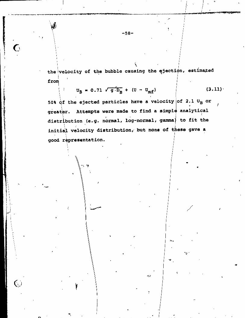
·1··· 1 ) .
1 •
__ ......j ___ IlAJ;te ... ~ ","4"h,.~1;i1f.f/~~IJ!iM
.-\~
-58-1 !
\. the velocity of the bubble causinq the ~jecti estimaJ:ed
(3.11)0
50% the ejected particles have a velocity of 2.1 UB or 1
Attempts were made to find a analytical "
bution (e.g. normal, log-normal, to fit the
initia velocity distribution,· but ese gave a
good r presentation.
...
,
• .r C'
-59'"
CHAPT·ER 4
. MODELLING OF ENTRAINMENœ FROM FLUIDIZED BEOS
The objective of this chapt~r is to develop a modei .~or
entrainJ'l'ent based on the arr-ival of bubbles -at the be~. surface.
4.1. Bubble Diameter Correlations' / /
1
There have been nutnerous' experimenta,l studies
aimed at characterising bubble behaviour ,in fluidize~beds.
Table (4.1) liata different investiqators and operating condi-,
tians for their experiment •• '
A number of correlations for estimation of the
Mean bubble'diameter have been proposed, examplea are c:;
Mori and Wan (22), Werther (23), Rowe and' Everett (24), ,
Geldar~ (25), Kato and Wen (26), Pa;k et al (27). ~itehead
and Young (28) and Yaeui and Johanaon (29). Table (4.2)~
aummariBes some of these correlations.
The Mori and Wen (22) correla~ion includea" the
effect of bed diameter on the mean bubble diameter. Experi
mental measurements of Werther (23) have,shown that bed ~ \
diameter do.e have a signifieant affect on bubble growth.
Theae observations bave a1ao been 8upported by theoretieal -.
~ ~
analy8is of the growth and cQ~lescence of bubblea in !lui-
dized beda (Chiba et al -(42),' Clitt and Grace (43), Miwa
~t al (44) ) wh!ch shows tha~.6B depends on bed di_eter,
distance~âbove the di8tributo~ and initi~l b~Rble di~eter 9
1 , f,

"'\
L i! ! %1 tA '.1$ ;as;:: A"I< .~~~.,4:d"'$:~).;;a __ i\"lIt(\!,P;!::,~~~ - --,. -', • ,~,.. tif" a ll't. 4! 4l\h$ CHi .,Qii!4L'+i'*'''''''l''!
~ 1_.; 1 '..;.../
"
TABLE ( 4 .1-)
~
~ ~perimental Work Regardinq Subble populations in Free1y Bubb1ing Three-Dimensi9na1 F1uidized Beds
XDvestiqators Experimental Dt(cm) Distributor Particles , , 'r~ique ,
Mor! and Wen .s130 (;1.975) f"
1fertber (1974-) Capacitanc::e 10,20, 45,100
'Fryer (1974) ;.\
22.9 , Chiba (1973) 20
. Rove dei X-raya 30x20 Everett (19;72) •
• / 30x30
• . Ge1dart (1972) Cinê-c&mera 30.-8
Porous Plate
,
Bubble Cap,
Per·forated.
Porous
Porous,
Quar~ Sand
Sand
Cru.hed Silica
Alumina Ballotini Glass Power'
. carbon , Quartz
Rounded
Dp(cm) Umf U-Umf (cm/s) (cm/s)
Q~006S SO.045 55 S20 ,S48
0.0083 1.8. 7.2 \
0.0071 1.7 7.99
0.0089 ,0.53 4.77-201.4 0.021 2.85 2.85-19.95 0.021 2.54 1.27-3.tll 0.0325 8.0 4.80-11.20
0.Q268 5'.50 4.13-9.63 0.0296 8.0 2.40-5.60 O'.~ 2. 75 ,~;30-15. 40
~
'-
Gas Obsesxations Bubb1es
Air Rise Velocity, Length, Size Distrib)1tion Gas Flow
Air
Air
Diameter and
Frequency
1 0\ o 1
Sand •
0.0128 0.0275
1.2 1.92-8.04 ~., -Frontal -- . Diaméter
Anqu1ar , Sand' 0'.0075 Air
• 0.025 • . 0.041
l
i t
1 i
! 1 i
1 1 i i
1 Park- et al (1969)
Blectroreaiativity
10.0 Porous Stain1ess
Steel
Conductive Coke
0.0086 0.0156 0.0344
0.63 1.83 6.8
1.89 0.92-9.15 3.4-13.6
Air "'-!- .... .. ~
-?- ~
-: ~.'
~ . . ~ i :t 1 r scôv r 7 7 t Tt mal 'WH'" ---.....1· no Nt ·'Sixt; ; nr r) tt,i
t"

~ v- , ..;........:..;
'-
Inves~i9a~ors Experimen~al Dt(cm) Distribu~or Particles Technique "
Cooke et al 60 Drilled rCoal . (1968) Plate
Whitehead arid Light" 61«61 Bubb1e Silica Young (1967) Absorption 122x122 Cap Sand • 1 _
-f
Kunii et al capacitaDCe· 20 Cuvas on M.S.Catalyst (196"1_~:- -- ---- -- 40 Perforated ~- Plate
.'
Wl.nter (1966) Silica '<, Gel
Toei et al (1965)
3.0)(10 Porous Glass Beads
Kobayasbi et al Lig~~ ~ li-, .1.Q (1965) AbSorp~ion '"
Remero anà Smith (19"65)
Biraki e~ al (.1965)
~ ~ ~ .~ .. ~
x - ray
Perfora~ed Crushed 4 Silica
Porous Glass "- "
FCC ) CaulYst·
&
...... ~
,j
D (cm) 't~ P .
0.025
0.15 -. ..
0.015 ..
0.0213
o.
0.021
0.0071
0.015
s. p
,Umf
(cm/s)
2.5
'2.0 1-48.0
2.25
2.85
~
~ j U-Umf (cm/s)
Gas Observations l' on
Bubbles !
2-14.75 2.75-13.25
17.0
Air Diame~er J
Diameter ~ir
Air Diameter and'
Frequency
1.13-6.75 Air
2.85-24.8 Air Diameter, 1
velocity,~ Partic1es 1
in Bubbles
Air
Bauagarten and X !. ray Piqford (1960) Absorption
7.63)(15.3 Porous Glass Beads 0~0074 0.727 0.73-59 Air Diameter and
Growth Rate of
Bubb1es
1
1 '. Yaaui and Light 10.2 . Johanson (1958) Absorption
"
\
"
Poroua Sintered, Metal
Ceramic
Silic~ Sand
Coal Glass Beads
Steal Siev~ V.O.P. Cata1yst
'0.007-0.023
0.045 0.0242 0.p175
0.006
19.4 . 7.56 4.70
0.418
\\
9.7-14.55 3.78-11.34 3.78-12.
0.4-3.76
..
Vertical ~en9th,
Air Velocity and
Frequency
i

'""_'f:'1"- .......... _,~"~ •• ~~~_ ... _ ..... t"". __ ~_ .... _,,~-,.-'W""J~*1 _.,*III$lf.MlM5;.~L1' """';;" li 141 •• air _._ .. ____ --..._~~! .. ~tn~'li'II-,.g jb8~
Q (j
@ 1
r'
-62-
TABL~ (4.2)
Summary of Bubble Di~eter C rrelations for Freely / 'Bubbl:ing F1uidize Beda
(For range of conditions etudie 1 consult original references) . Mori and Wen (1975): DB - Dam-( sm-Dao) exp (-a.lb/D t )
where Dam - 0.652 (At CU-Umf»2/5
and
or
Werther (1.974):
o ' 4 Rowe and Evarett
(1972) :
Geldart (1.972):
whara
Dao -
Dao • 0.347
DB • 0.853
, , 2
CU-Umf) • for porous pl~te diatributor
At (U-Umf)/n) 2/5 for perforaeed plate diatributor
(l+0.272(U-U~f»1/3(1+0.0684 h)1.21
1
DB • -A+Bh+C ~)+Dh(~)+!(~)2 ml ml mf
DB • 0.027 h (U-Umf)0.94+Dao
o ". ~ 43' «U U )A ln) 0.'4/",0.2 Be ': -m! t ':J'
Kato and Wan (1969), _Os • u ' 1.4 Pp Op ( 0::' h+Dso
mt
whera
Park et a1., (1969)
Whi tehead and, Younq (1967):
YaauilaneS Johanaon (1958):
Dao • fA ' (~(O- »0·~/90.2 'If' ft mf'"
D • 33.3 Dl • S ( U _1)°·77 h B ',P u~ .
DB • 9.76 ( )0.33(0.032 h)0.S4
:f " ,

•
io "Ito '"''&;1''' are ,. tIil_.OMM'4:t1i,
-63-
'r
/
at the distributor plate as well as on ~he qa$ flow rate • .
Some experùnental data and correspondinq predictions
fram several correlations are plotted in Figures (4.1 to 4.5). b
For the conditions studied, the correlations of Mori and Wen
"'(22) and Werther (23) predict lower values for the, mean •
bubble diameter than experimental data of Geldart (25) and
other workera. Geldart's correlation predicts bubble dia-, ,
• meters for U - O~f • 13,19 and 31 cm/s whiïf are in reaaona-
ble agreement ~ith the experimental data of Cooke et al (45)
as shown in Figure (4.3).
In the present work, a r~asonable estimate for
Da ia obtained by aveFaqing the values predicted by the
correlations of Mori and Wen (22) 1 w,rt;.her (23) and Geldart
'(25) pro~ided that Geldart's correlation predicta bubble'
diametera les. than th. bed radiu8.'~This choiee for est1mating , "
bubble diameter provides a compromise between Geldart's
correla~tion, which agr ••• r ••• onably with experimental data 1 -
1 shown in Figures (4.1 to 4.5), and the Mori and Wen corre-
lation which is more recent, agrees re.8on~lY with recent ~-
data like that of Werther, and accounts fo ~he effeet ~
bed diaœeter on,mean bubble diameter:
lt i. worth notinq that all correlations seem ta ,
deviate more at h!qher values of 0 - Umt and h~9he~ bed
heiqhta.
1
..

\ \ ---:\---- ' ...
\ CI
, ... , .... AdJ,etH"Ui2!ilMlUaf! ! 1
-64-
'. ~
Mori and Wen $;orrelation 'J
18
16
14
12
1
-e -
4
2
(',: q~i
,0
--- Ge1dart correlation
------ Werther correlation
---- Ge1dart'data ... ,"
~ 1 h - 60 cm
2, h - 40 cm
3 h - 20 cm,
l' 1
1 2 ;,3 1 5 , ~ - Vat (cm/a)'
1"/'. P
FIGURE (4.'1) t Bu~bl. 4;ameter veraua . \
6 7 . 8
, ..... 2 ,;'
9
. - \
r "
, .
,
U -: ~ for .3 bec! heiqhta.

o
G
" - .
-ft --ca Cl
o
10
Il,.
-65-
...
Mori and Wen correlation
--- Geldart eorrelat~on
--_.- Werther correlation .. '
2 U - umf • 5 cm/a
1 1 l : ,
',0 20 40 ,~ 60 ;. BO" , 100',' 1aQ ti .IGIT. (CIl)
- , . ~ PlGUBB (4.2) i Bubble 41am,ter versua be1ght.
" , "
• r
,1
, ~ 1
,- -
....
o
140 ~ 160:' 1€O •
l' -, - ,

, li 1 ~
AL" ~ ~~ ... v~ ....... .... "" .... 'Y>.r"r~"~ .. ~I"~_~~--q~...1~'D,~'Wi lhl ... __ ,.,~ __ -_ ............ , 44.4 (Â"~h"~~'i~f)*$J4.,~(Il\'tI~I,,,,..,.. .-~
• 1
(
o
"
i/
<
" "
ft •. , J
J_
. '
!
, C il .~ Ir ':, rl r i!t '
1 L~ 11 " If ,II ,
1/ " /, )1
J, ~
/.1 "J! l,
. III
Q'
, . .. ,1
.. -66-
d \
t \
Mori and Wen correlation
Geldart correlation
• 1 ~' -:....._._._ Werthet correlation
_ .. _ .. ~ Da,ta of Cooke et al
J.
"~)I '10 3q 40 50'\"' .., -' BBXGB'l' (cm~ "
eo 20 . ' If 1 //). "
"
PXauRs' (4.!) J BUbble diameter v.~.u. h.19ht • " ' ::' ,,/ , , .
" , '.
l
"
70·
ot
. ï (.
a •
lit
/

, .
\ , , r
, 0
en , ~:.
"
r
"
-,
\ 1
..
l ;
ri
/
11
10
8
,7
6
-8 5 -al
Q'
4
'1 3
,('
2
1
0 ...
,,'
'-- PlGURB
? -, 0'
l _
\.
'\ '-67- " J
: 0
i -"" &'
~ " ~
Mori and Wen correlation •
Gerdart correlatio~ .f. ....
_._._.- W~rther correlation
1 ,2
(4 .. 4) 1
\,
• 1 , 'l'.
, . , .
- ~ . ot Yasui~and Johanson
ÎJ
\.
:!-
'6· 7. 8
u :- :~mf fOZ"",h ~ 25 cm. ..' ' ,J
" "
...
" .,.
J ,
,'.
..

•
t,."
\0-f ' \ i l f f
~ ~
10
9
8
, • .. 7
a . '"
6 ..
- 5 \ 8 -
CQ Q
([~ 4
1
f
3 "
, ,
4 •• sM; l ,.,ft AHN. "' __ Jill b cl •
-68-
.... ,
- ,..'
---Mori and Wen co~relation
~Géldart correlation
_._'- Werther correlation
_ .. _~_, Data of Park et al:
1 h -30 cm l
2 il • 20 cm
3 h - 10 cm
'é
/' ~ /' :...r .. / '
. (,./ // . / ?
p/ .- h//
#'
. /~ , ~ .iI
~-"
J 'fi" ? , ~ 2
/,/ --~ --~-
,t'
, '
1 fi ~
,
3
---
,
l'

"
\
a t,l, 111111"1 1 ,
LI -69-
4.2. Bubble Format~n by Injected Gas G
If 9a. il injected tftrough an orifice into a ,
'fluidized bed,Q~ubbl •• fo~, detach .n4 rise to ,the bed .. surfacee It has be.n found (Rowe and Partridge (38) ), tha~'
the aize ot bubble produced vari •• linearly'vith the yolume
of !njected gal, but the a1ze de;~nd' strongly upon th~ background floy' ot the flu~i1zin9 9as. Rowe and-Partridqe
(38) reporte<! that th.re i. • threshild volume of injeoted
9a8 below which ,non bubbles fom when the bed 1a at Umfe
E2çce •• qas above thi. thr.aho1d volume, reported to he 40 cm3 :.
for the expertmental conditiona 'studied, would form a bubble
'ot only 701 of tb~' axc •• s :VOl~,~~ rem&ini~g g •• leaking
-~-~bl. lnt~ the den •• phase. The thresho.d vo- '
l~e wa. tound - 1:0 c!ecr.~.. as U". vas. in~rea.e4· beyènd ,Umf 1 "
., ~ :; , . .. ,
until at U, • 1.05 u.,.the volume of bubb1ea formed i. equal • q • ",:--~
to the volume of injeote4' 9 ••• • At bigher supert1o~as
v~lociti •• , ~h. bubbl~ formelS ~y he apprec~~arger ___ ~ - f
than th~ !njecte4 volume' c!~. ta bub~é~le.c.nce. Harrison
and L~un9 (39) .... ureeS the"front.l cU.~ter of bubbl~ domea
•• 811191. inj.,t:ed bubbl.~ b~Jc. the 8urface of a fluidilec! 4 ~ ,If ; .,), ' " , < ~~~' ,.'~,. , , '
beèl. J'rom a 1a~i. nWQbu "qf 4ataf .l.l .• ~th the auperficial :-
9a. V.loCi i:.;- !l:~- ,5 to ~O. ~. ~~t 'r~lted for' 1no.1pient . , ' , . . ., "
flUi4J.~.t,i,o.i, trhe~ t~~, '~;'r~! . '.; " ,. ,n ' '--1/3 ' ' -' "- t. ',"
Df -iII: 1,_ 92:v- . ) f " ','" ':'
- ~. '\ ' ...... ~ J ...
• f! , ,', 1, ~ l , ~',)" ~ , ~ - , ' ~ 4 , ~ , ,
" ~ .. , " .
\ ':<'/;"'-<'è:' Ji: "
" }: ~;" " 1_'_' _' __ . __________ •

o • wmr~)i"..~'I~_ 01(1!!S Ui'. oH; ,_m. lualll J 11/111 .... • -1: ________________ . ___ '4_._aLA""r._LQ~h_ •• AM4.n, •• , ... U.-__
f , ,-~
t l' r< r r
~ \
~
Q
"
o
., "
l,
, .
1
-70-
•
'. or Of ··1.548 'DB ' .... (4.2)
, ' l '", where'oB ~s the sphere,equivale t diameter of the injected
volume of 9as, V, not neeessari y equal to the actual ,)
bubble volume as the bubble hes the bed surface • ., .
4.3 Bubble 'iae Velocitx
, Several investigato; have measured the ri se ve10-
city of bubblea in fluidized b da using varyin9 experimental ~. \..
technique.,. Harrison ana Leun (39) 06S.rv8d the time in-. \
terval ,~etween the injection 0 th~ bubb1e at the base o~ li-
the" bed and its arrival At. th bed surface in a .bed 61 cm , .
square in cros.~.eetion·wit.h U ~ 5 tQ lOt abova Umf • They l " , 0
obtaineda
UB • 0.71 91/2
V1/
' •
( (4.3)
, . ~ or equiva1ently Us ,- 0.637 9 B' (4.4)'
"'lere Da 18 tb ,;..~ equ:LVa~ellt ~i_t:~. Tbe volW118 .of' "
I·g~. infted ~~ecS f~ 25" ~ 10,000' .çm3. '~é aJid P~"tr:1d9.
. _(38) \ls\, X - ray pho~J:'.pJ)y ~to I;"e •• uret b~le di~t~r8
. and ~i •• ve1ocit1e.'-.riel obta1ned •• !milar corJ:'e1âtions 1.
'- UB ,- 1C {g'fijl2 ,.' ' .: ( :, ,
'l'he .,c,oefficieht, ic, :'Wa. ïôund by ~.a.t 8qu~re.: for
(4.,5)
~ch o~ ~9 '41ff.rani:. .. ~r!f'~'~· ~ v~rled ~ro. 0.8 to :~ .. 2· (
~it:h à.r:vù ... va;_ Of\M4~ ~nd 7.~.~1~ ~~3.U"~. • ' \', ' , ~ J' , !. - • v.
~ < ~ '\ . '" ~ ~. ,~' 'f"~) ---' 4 .\~ ~.. ' " 'l' _
, , .,' /'/" l" ,,,"" ')" • . .
, '. ' .. : .:::' .>.,~~:;~ft:'f..' ç;~.'!!:::<i~l·< ;~}::j .' l ' l, ' ,

.. \
1 1 ~' "'~~~~~'~U_.,j.,~ ___ ._·_;_' ___ "":tllft ____ ._,_~_'--,.. "- ~ , , .. , 'J SI l' .... il 1 ••• 0 t '.'!ld "li
f ' f
1
• , l t
"
..
1 , 1
, ,
J •
;:;
J -71-
, ..
15t of thi. value. \ .
For J{ • 0.94
UB • 0.67' {q Os .,
(4.6) " f
For .warma of bubblas it is common (e.q. see Davidson "
and H rison (30),) to add a tarm (U - Umf ,: .. r
UB • 0.71 {q 6B +' (U - Umf ' (4.7)
thi. term was oriqinally add\d due -to continuity
derations (Nicklln (46», it ia preferable to view it
as elY,an ~Pir~cal addition' to ~he ;e~c~ty in isolation \ \. -j .
h arises due to bubble inter~ctiona (TU%ne~ (47), Grace
~ation (4.'7) aqrees reasonably w).th 1 •
and Harrison (48». - Ir'
ex rimental data for bubblea rising in awarms (e.g. o , " L ), "
se. (49Q' •. . ' 1 ..
- . ç, 4.4 Visible Bubble Plow
Th. visible bubble flow rate at the bed surfa~è ta l r
,
\

"",
\
~.'
-72-
4.5 Bubb1e Ve10city Dissipation
-T~e surface 'of a f1uidized bed may be consideradAs . ~
1
a plane in which are located a numbe' of nozz1es whieh ïnt~r-
mitten~ly jet gas irito the space abo e. The intermittent~ ~
nozz1es correspondUto gas bubb1es b rsting at the bed surface.' . From the theory ofaxissymmetric·fr e jet dissipati9n lnto
stagna'nt. ga8 'of the lame f1uid (Abr ovien (51», the centre •
1ine ve1ocity, Ux ' of a steady lent gas jet dacaya
. according to: Ux -. 1 Uo
.. ~ x • x + 0.29 a
(x" < -
(x"
0.96 Ro 1. '1 a
0.·96 Ro ~ ) a
Ro • radius ôf the jet .t the orifice
a • dimen.ionl ••• con.tant, 'approx~tely ,eq\lal , l , . - ,
to 0.071 ..... • -,
(4.9a)
[.1 (4.9b)
-.
Aaauming that the initia~ diameter of bubb1e-induced
jata in the fra.board- • DB" BqUationa (4.9a and b) auggeat . .r:-' . '
that jeta in tbe treeboard m:l.ght,4ecay according te'a rela-
tionahip of the forma'"
.. .
. , ) ,
, -' ~ ,
,~ ,;- J: '. ' ~ ...
1 (4.10)
(4 ~ 11)
\
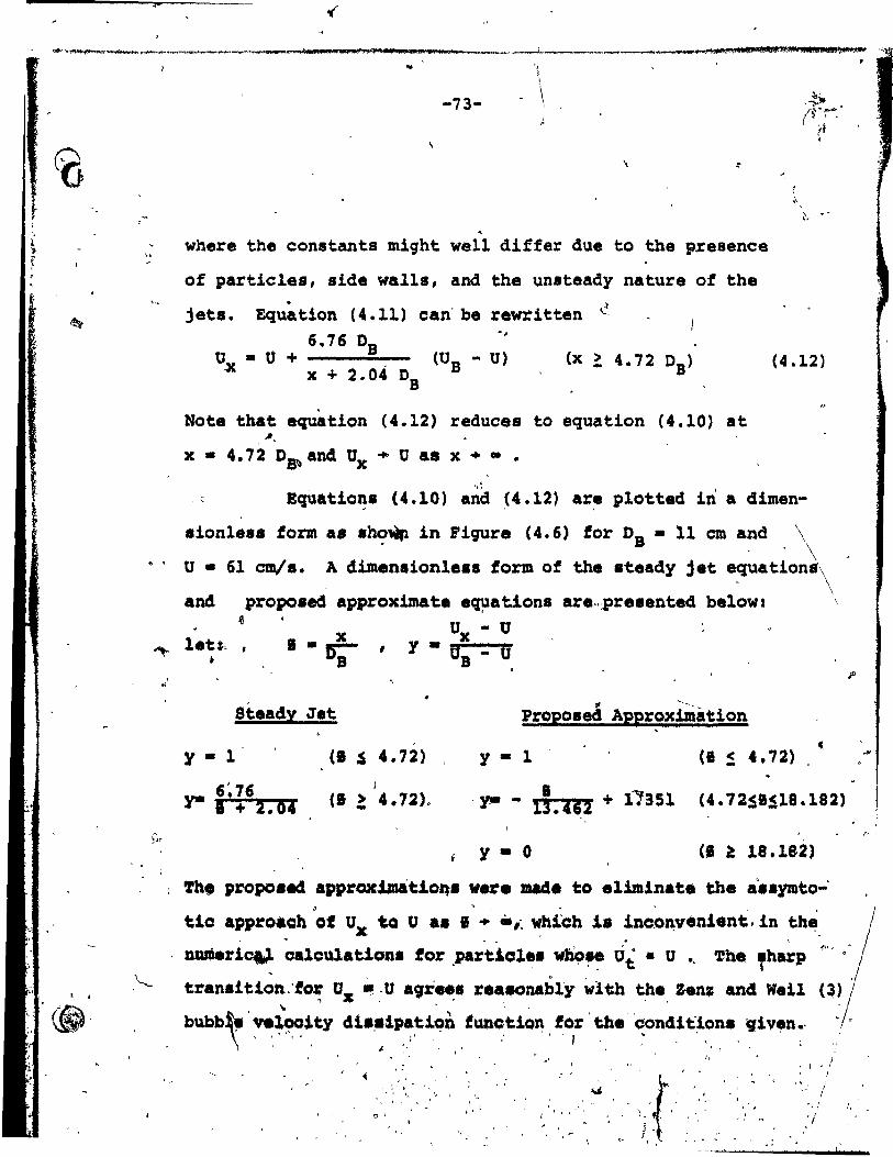
, "
\ F ,
~ ... ~",~,...,-... __ ~ ______ ~_ .. .,._, _____ ,.,..., .... , ........ _, _, _ •• 11_'_4 .. __ ._ .... ~ _ .. ?' .... _______ IIIl_ .. _zl ... ""'klifIi\ ... U _'il"'IfI!I!;I;IU""l!""'''''''',:~t'''II!tj ..... m •• $III'IIWI~I!!."","''''_'Il!I_ H,
~
~
... "
-73- - \
, where the constants might well differ due to the presence
of partieles, side wall., and the unsteady nature of the
jets. Equation (4.11) can' be rewritten ~
Note that equation (4.12) reduees to equation (4.10) at
x • 4. 72 D~ and Ux ... U as x .. • •
, \ .' "
(4.12 )
. ' EqUatio~s (4.10) a~d (4.12) are plotted in a dimen-
sionless form as .ho~ in Figure C4.6) for DB • 11 cm and \ . , ' \ o • 61 cm!". A dimen.ionles. form of the ateady j et e~a tions\
, \
and proposeeS approxima te .~ation8 are,.,presented below2 \ ~
""" let:.. • 1. x
Da , o - u x y • U - U B ,
• 1
, "
Ste.dy Jet # -••.•
Proposed Approximation (
CI .s 4.72) y - 1 (1 ~ 4.72) y • l'
6~76 y- 1 + 2.04 'y- - 1;.462 + 1~a51 (4.72SIS18.182)
y • 0 CI a 18.182)
The pJ:Opoaec1 approx.tJD&ti~ ver. made to el1minate the .'.symto-'
tic .ppro.ch DOf Ux ta U •• 1 + .,~ ~hi~h is inco~v.n1.nt, 1n th~,
numeri~ ~.lcu1atiQns for ,pa~tiol.s ~~~ tii • u '. ~b. fhatp
transition:to~ Uz ~:u agr.~s r.a~nably vlth t:he, Zen; ane! Wel1 ... " ,
bubb~ . ~~itY dJ. •. ~l~~~:n . !Üft~t.ion . ~~r . ~:.' ',!on4i t~~~. _ ~:l ven~' , t.. \ f, •
" , \ ~ ~ <- '~
, i J~
, ~ " ~ 1
" ' " '
, .. '
, l >! 1
",,' 1 "'./
:1
,
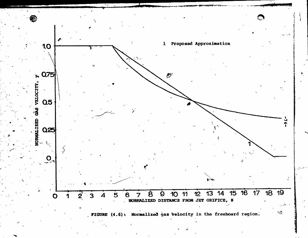
~ ~ ',. ..
l'
lit
-'. ~
JI.
-~.
....
~ ----_----......-~ ~ "- ~ __ .. ~ '?~ ~P!~U: LU 4 ;: @WilH;Z;SP..,
" " J
-"tP 0 ~ 'fi l. ,i 1 '1.
r
1-,
~
~,,-
"
" , .,
J
~ " i (; ,
" , -. ..... 1
!
tO 1 %cc ..
.. i: H .
8 .'~ Q5 ~a
O..y, "'z- ~
~.
(
o
5
,'-*
Q
•
~ ';
. - ,
. --' ".----- . • d •
o 1 2", 3 4 5 6 1
7
l Proposed Approximation
\ ". ..
~ '- ~.. 1 ... ~.
-4
'( '",-
~~ -
, . 1 • • 1 1 1 • 1 ) 1 • 8 9 '10 11 12 13 14 15 16 17 18 19
DORHALIZED D1STANCE FROM JET ORIFICE, B
FIGURE (4.6): Normalize<J gas \relocity in t.he freeboa'rd raglon: '''''~
s,-
• ..... ... 1
1
,.
......
l_.;:·-': -

•
" A { ___ ... _,_~~_._~_, ____________________ ~ _____________________ ~ _________ ._*_,~"~~~~W~~~d.~~.'~~~",,~~~M.~
o
1 ,.
o. -7\5-
4.6. Entrainment
Entra~nment of partie les- from tLuidi~ed beds ia
determinediPY what '~appen8'Within the d~n8~-Pha.e bed. what \ ' happens at t~e surfape as particles are transferred into the 1 •
dil:ute phase 'reqion~ \, and the trajeetories of partieles in
the freeboard. Any ~oherent'model of entrainment must takèl
\ \ "
all three of theae fjetèra int,o coneideration. .The model in
the present work, dgea\ thia aa followa: .
. '
Dense-phase, Bed: 1\0 Correlations already diseuased in this
chapter are \1884', to eatimate the size and veloeity of
"bubbles arrivinq'at the' bed surface. Specific~lly, the
Mort and Wen, Werther, and Geldart correlations are averaged Q , ;j • -
to provide an eat1ma~e of th~ mean aize of bubbl.e arrivinq . -Jf
at the bed surface as di.cus.ad in Section ,,{4.1.)\ -Equation " .
\.
(4.7) is used to eetimate the velooity of th.s. bubbles.
4.
Tran.fer of Particl •• into Di1ute Phase. The volum. of
partiele. ejected by .1n91e bub~el has be.n detemined as , , . , .
dilCu •• ed in Chapter (3) tor th~ee repre.entative typea
of,partiel.a. Tbe veloeity 4i.~rtbutio~ of partieles haa , . ,
alao been d~uced uaing mea.urementa taken at different '.
haighta abOya the,~ .u;tao~ fqr n~~~ly moAod1.Plr.~ part~-~ . . "
cle •• The •• 'mea.urementa are &lao dl.oQ •• e4 in Chapter (3). 1 ~ Il ,
- • \> ~
The f:L~"in9 t~rj.~~~g parti~l~s, ,oJ:igina1:e fZ'iII~ily' tram,
; l "1 ..

'\
o
ment
(a)
ra ... * 1 _ ..
-76-
bubble wakes indieates"that ejeeted partieles should
be representative of the size distribution of particles
within the bed as' a ~Role.*
" \ Partiele Motion Within the Freeboard: From the results
of the two preeeding paragraphs, we ean estimate ~he
distribution of partiele velocities and the flux o~ particles
with each velocity. Trajectories can then be calculated
using a simple fluid mechanical model whieh bala~ces gra-
vit y, inertia and drag forces for particles in' the free-.~ ~
board. This i8 e8sentially identical to that described~
by Do et al (1), but.w~th small modifications, especially
the add~tiqn of jet dissipation ~n the fréeboard;as de~cribed
in Section (4.5.),to raplac. constant lupJrficial gas velo
city used by Do et al. l '
The numerical calCU1\tions'to predict TDH and entrain
bath halow anc:Vabo91 the 'TDR proeeeds as follows: . ;
Calculate ~itical partic~. diameter, Dpc' corresponding
to partiele. vith Ut • u.
~ - ~ . • Partie le segragation may occur under certain operating condition. a. reported by Rove and'Ni.now (31) .and Chen and le.irns
c (62). ln thi. cale amA1I o~119ht partieles se9regate at the .' top of the bed wh!l. large qr hean partial.. ..ttl.lout at the bottotn •. ' Under auah aon4±tions ejeetad partiel •• mi9ht--:~-"
. conta in • ...11er' fraction ot the amall, or 1ight partieles th.J1 the be~ _proper • '
.II
1 .( .1"

.. ~- '~J\t .... ~"",..,....,........,., ................ .,...) _ ........ _"'",",'_*._43_' _ ...... ___ ....... "" ........ *"''''''''' .... 1&'''''"' ... tt:_ ........ """._. ___ .. ,_. __ .:.-... _____ _ ... id a Il lM! .!8I*",.4 .... !.-AJ%WJ" .. , ... ~
o
~
':'77-
(b) Subdivide tne bed partie le size distribution into a
) number of repre~e~tative partiele sizes bath above and below
...
, . TOH i. prédieted usi~ the modified trajectory mOGel
..."
eorrespondinq to the ,maximùm heiqht, hmax ' reach~ ~y partieles
whose Op ,> Ope vith t~e-hig~est value of vi" A check vas
made to ~ompute ~ for repreaentative:part~ele~ vith Op > 0 pc
80 that the lar~est value of ~ was ehosen ta represent TOH.
Sinee,bubbles vhieh coalesce AS they reach the bed surface Q
have been shown to qive part+çularly el\ergetic, 'eruptions vith ~.:~':J
abou~ twice the normal value of vi' aafer estimates of TDH are,
obtained by doublinq the hiqheet bubble veloeit~ value, Us' in
conjunction vith the hiqheat (vi/US~ ratio.
(d) Calculate the flux of particles ejected at the bed surface,
Po' tram \
po • 0 Pp (1 - Cmf> , G.s/A (M/L2T) (4:13)
...,
where GB • i (U - Um!' A " (L3/T) , (4.14 )
"''Y ~.,.
The noxmal~. vol~. of ejacted partieles, " is caleulated
~ from f!igure (3 •. 4). '.
\
(e) Par particl.s with Uti~~ U, the mass flux for.~ach part!el~ . f\ '
ai.e fraction 18 2011pùta4 from the product of. F 0 e.nè!~ the- weight "
fract.ion of the, partiele .1... ~i. flux li ••• =e4 cons~nt a8 ' 1
a function of heiqht in the fr •• board. por each partie le lize 1 \ • ,~ ~ ~ •
and lnitial,pa~ticl. v,locity the ~~icle concentration '(MlL3) .tI,
, ,

, l'
r'
"
éJJ:;:., , , <
\\yI ,
.'
" . • 0
.' ,
111111_'. • 1 •• 11 _ .. t81 14." .;l'A'',~~~S!fII'\!I! • ~
. ~ \ . -,
. ;~ , J
i8 com?uted from:
-78-,
"
Ci'j • Fi'j/Vp (4.15)
where ~Ci'j • coneenttatio~ of partiele of size Dpi '.nd ~ ~ \
, . ~, in~ tia4 p~rtiele veloci ty v j .
, ' ,
Fi'j • Flux,of;partiele \t aize Dpi and initial . " veloei ty v j •
o ,
Yp • P~tiele valoeity computed from trajeetor-y\
model.
The total'eone~ntration of aach partiele s~ze' fraction ia
, eomputed by awmning, '" .. i.e.:
~ jaN , " Ci - t Ci'j
j-l
"'(f) For patt~cles returning'to:tJle bed (Uti >'U), the fl~, , ,
Fi' j' is computed ·ali a ,functlon of' hei~ht. The total flux
eorre~~ndin9 to a pa~ticle of aize, Dpi' i~ computed' ~y .ubtf~~ting the fl~ ,of the partie le, vith tbè lowest v1 trom
\
, "
','\t~e têita~~t,a4 flux corr •• pènd.1ng to t'_ ,partiele slze ,frac~ ~-10" \ "\'1' .-
i tiop. opee ~ has bèen r.ac~~ for. th... article. ,_ Thi.
:\ proc:èdure 18 repeated for the next lowe't j ,and sO' on u~ th_ '
, •
. ~
freeboard until zero flux, for that partie e .1ze,~d.s obtained \ , / ',. , ·1
/ at,the ~ corr_.po~dinq to the hi9hest v lue of ~j. The
,
._. upward and downward partie~e mas. tion 18 cOJlputecl , ' \.
fram: , . '. • 11 ~
'~ ,\
•. ,~x/ .d~ '" \, (:,<
• <il . .' ~
. 'J

\ • , .
,f ,', .. 1r"'~"l"tW. ... ~ ___ , _ ...... _____ ._ .. _._ ... ""' __ .... "" __ ....... _'"'"FJIIFIIIt .......... ____ ....... I_....."..-........ ' _____ "'--___ ..,.~.-...... _aIl! ____ "
\'; t
, 1
, 1
-7.9-
,<) J'
( . }.
(4.17) " .
: ~nd (4.18) ) 1 • 1 The total p~rticle ,masiJ . . coneentrat1pn is·Jthe,n obta1ned by-t
,0, ,
....
,;
~ 'i-,,,, ~- ~, '" .,
summing the upward\and downward,poncentrations. j J '" ' u
,(9) The to~al part\cle flux and total partiele mass concentra-.: .. .( li'" l j
tion ar,e obt.ined by ~~ng th.' 'fractional co~tribution8 of
flux and ma •• ,concentl\ation for each particie fraction.
"
1
J~ , J Q
~I
" :::!.
p
j',.
•
Q
.,.
, ~ .
, ,l-
\
\ \
1
~'.
'" , \
~-tt
'1
"
, '('
" ;,.1:
. 1
.. ' 1 , Î
1 * " i'
, "
o
. " . .
:
" '
~ , • ; t.,' ,. ~: 1:" ~ 1 t
\' '- ~ --'---~-_:' '~'-":~~~',--,L'--: "~.~} .. > "':;'.
, ,
'b
" '" .f __ f;_~ \.~ ~~~-=-~',--"'~"'-~~' r l j
~, .
, .
, .
1
,~ .
• </'
"
. "
1
, ...... 1 "
. , lMoi .. " a,." __ ,œ 18.
-80-o
(
·.U,'t li "]
, ~ ..
O ' , . \, ~ -.
CBAPTER 5
>APPLICATION OF ENTRAINMENT MODEL 1 '........ 5.1,. Mass Flux of Ejected Partieles at the Surface of the Bed
, .
-
~r-... ! j" ~I -:' fi
. The mass flux of ej~eted partieles 'and the distri
bution of partie,le velocities Jlt the bed surface. -must be 1
:Jcnown in order ta caleulàte pa~tiele t~ajectoriJ' and entr~'in-. ment i~ the freeboard- both balo" and. above the TDB. ,Thè mas.
flux of partiales at ehe bed surfac. may ~ estimate~ simply,
as: '/ , l
, M -,- p . (1 - EJQf) t (p o J P,. (5.L)'
~
" ".. , .. , (
where t. l'a ,obtained f~rOJQ, 'Cbapter' ~3), Figure (3.,4). ,This " - '
éffeetively as.~. that the viàible bubble flow i8 half "
', .. t~~ 9iV~Y tPe two~phase theory. Recently same light"has ,
been shed a,n entrainment at the surface of thé bed (Large et al
(13» that"makes éomparison vith this estimate' possible. ;:" 0
,Large e~ al bave 'measured bath total, partiele aseending flux "
and,fractional 'entrainment for par~ieles.of a KnOWn s~ze IJ • ~
distribution at variou8 heighta above ~ bed surface. The~ . , then COlllputed partiele ascending fl~ at the: sw:face " F 0'-
by extrapolati~q f'ractional entrainment eurves to heig~t,
zero*and a.suminq the relation:
. ' ..
" '
" .'.r
, .
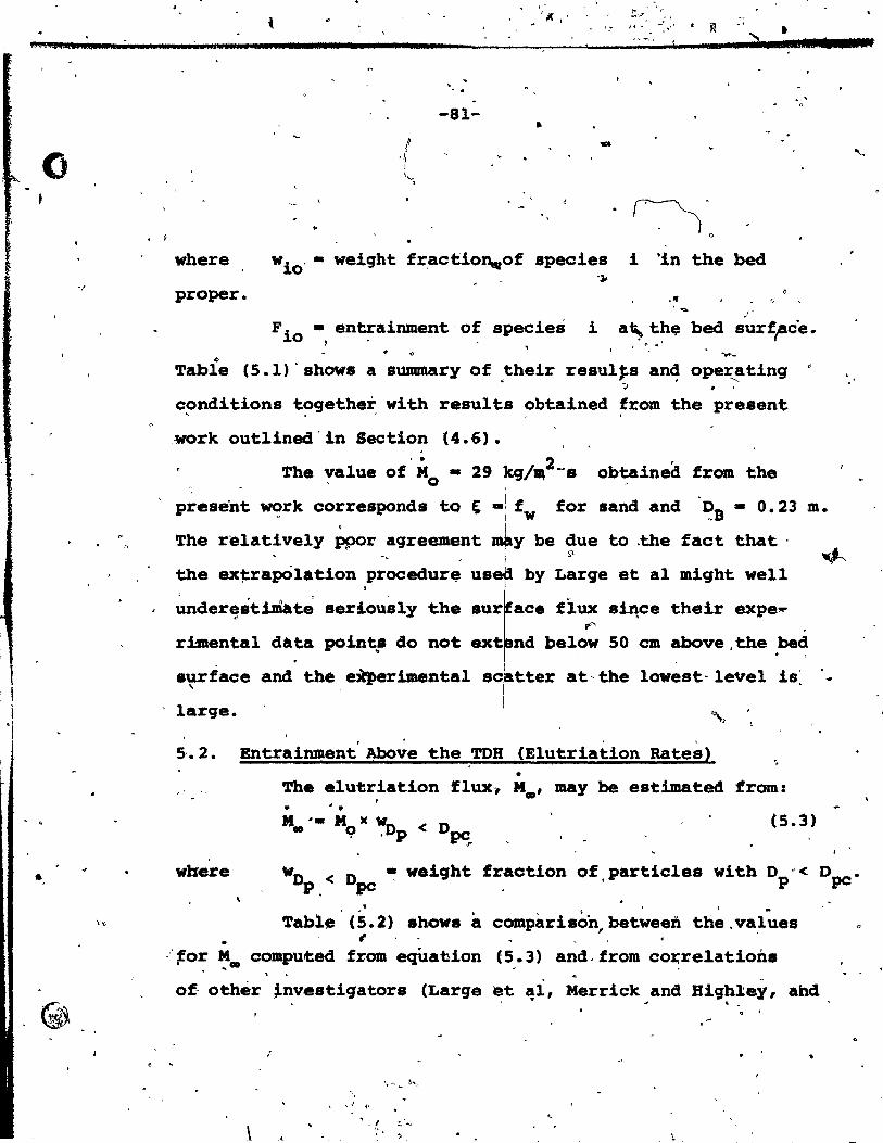
P.c. Z:AW
o
"/
" ,
•
. ,
• 1
fA J' .. ). a ua 1 bd
vhere
proper.
"
-81-
~. o
vio' • weiqht fr,act::io~of species i 'in the bed 'Jo
r
. ' o
F io ., en~ainment'o~ species i a~ th~ bed $urf,.ac"e. , '.
~
'l'able (5.1)' shows a summary of .their resu1~s an~ oper-....ating .' ~ . .
conditions together with results obtained fram the present , .'
,work outlined'in Section (4.6).
'l'he yalue Of'Mo • 29 kg/~2_8 obtained fram the
present ~rk corresponds tQ t -: fw ,
for sand and ~B - 0.23 m. ,
'l'he rélative1y ppor agreement y be due to .the fact that . ...
the ex~apOlation procedurf;t us by Large et al might weIl
~er~stiM~t~ seriously the ace flux s~ce their expe~ 1'"
riinenta1 data points do not nd below 50 cm above, the bed ~
surface and the ell'perimental tter at- the lowest- lavel is~ , large.
. ,
5'.2. Entrainment Above the TOR (Elutriation Rates) ",
• Tb. elutriation flux" N., may be est~ted from: . . . . M '. M )( w,O
• 9 .p<D~ r
(5.3)
[ TI '
where Wo ~ weight fraction of,particles ~ith Dp'< Dpc. P < Ope
, . Table (5.2) shows a comparison,between the.values
• i :'~or M. compu~ed fram eqUabion (5.3) and,from cOI:'relations
.. ..... ... 0-
"
of othér ~nv.stiqators (Large et ~l, Merrick and Biqhley, and . -. . ;
-, ,( (1
\
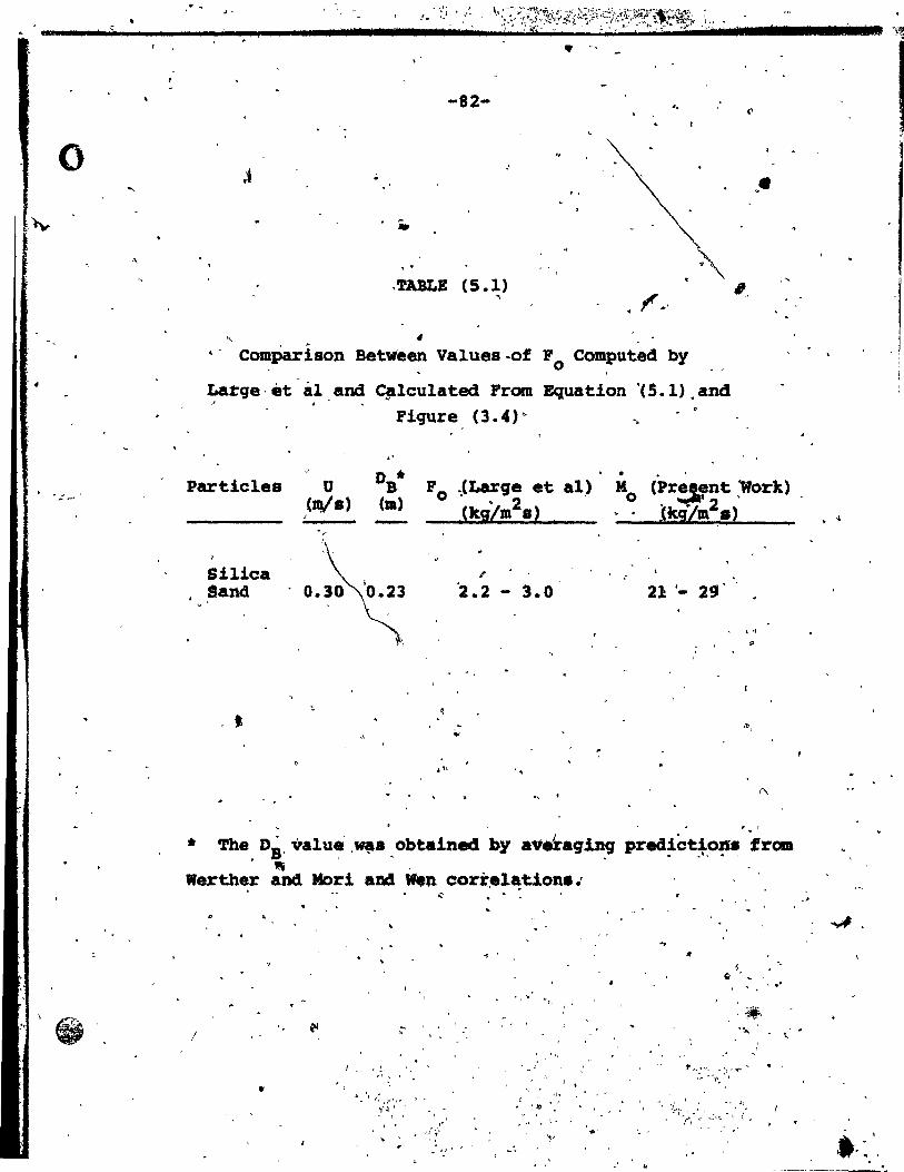
i.'IIo ln L Il
o
•
,. ~-~
S' . "
-82- '.
. ,
.. .TABLE (5.1)
"
" CDmPar1son Between Values-of Fo Computed by
Larqe,èt al and C,lculated From Equation ·(S.l).and "
Figure (3.4)"
.' •
••
,-..
Par tic les U D * S. Fo . JLarge et al) Ho (Present 'Work) (uVs) (m) ~kiLm2s)
..... "
lkg-Lm2s} 1
, 1
Silica ., ,-
Sand 0.30 '2.2 3.0 21 . - 29' ,
• '1
"
.\
." " .
* The, DB' valu~ ,,,, • . obtained by a\f~a9'in,g prea~o~,o!l~ 'frca ", -
Werther and Mori and .. n cori:.l~tion • .' '
, '
'" '
- , . ,1 . ,
1 !A 1 t, .. ' ~ <
•
" l ,/;
" ~~ ~ J' ~
"
, . , "
',~ t .. ' " '
"
"
, .' , -, -'Ii~' ... ~I
",--~ .. ~:~.,.",
nI ['dl'~
.~---'-

~- 'l.., ~ ..
~~'-____________ ~_·~~_-~_"_' __ ~'· __ """.d.:.~.,.t.~,~_,~_"_: ___ ,,~t~~~t~~;~,f~~~~:~~::~,~,~:~r~~~,~:~'~'~:~~'J._;~:~~\~;:_:~_::_".~"F.':.J"l"'.-""""'[~
o
"1-
,.
-83-
Il ..
..
~ . TABLE (5.2)
. ", .
E1utriation Rate Resulta Computed From ~. 0
~ati9n (5.3) ~~~ ~r9m Other Investigators
Operatinq C~nditions S~lids U (ID/a)
FCC.,
-D - 60 J,1m p-... umf: - 0.4 ~,
)
'sâridÎs2 Luqe· et al)
Umf III è cm/a
0.61
.,.-'
0.30
Elùtrlation Rate (kg/m2.) Present Large,et al 'HerriCk- 'Zenz
WOrk and and ___ ~~_I. Hiqhley ~!!!1:!
• 33.8 N.A. ' 29.5
.\,'\ t< .-
,-" 1.26 o.oa B.A. ','R.A.' 1
ri
" '
" ,
1
• -: ....... j' 9to ,
• • partiel.s. Sand wit:hr.l~. 4is~~tiOn a8 given'by )La!:ge et fl (13), type. S2. , '-
.. ,-"!l,
J -,r-: '. ,>
.. " '
.. ~<'
"~,~, < ,;(
-; d
, . , •
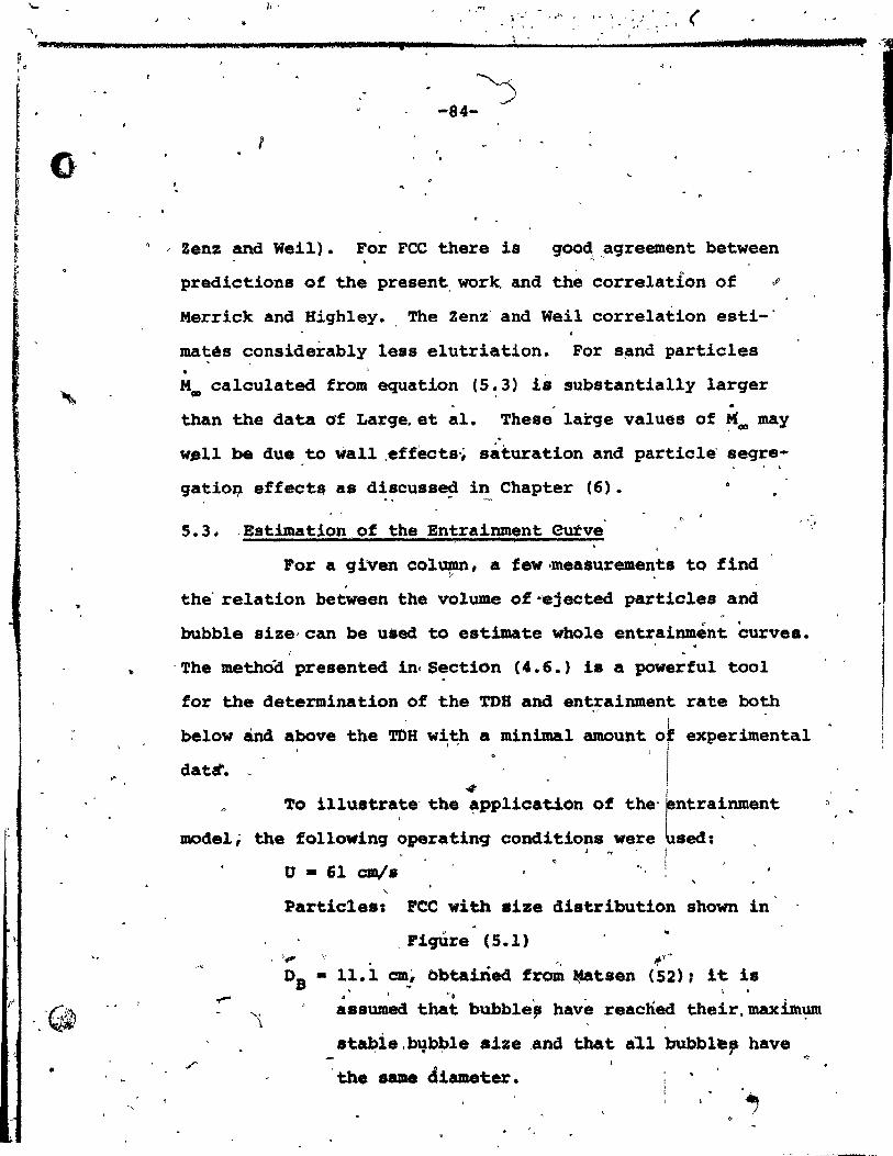
1.-
"\ , "" ...... 11 ~I" •..... ,.
F , . ,
0
~
~
..
,"
..
.. -
'.
/, ' , .-1 , , , - ( ;; - , ,h , ' " - ,
.'
1 1. 1 • , •.. • n .1 li .. Il 1.
, ,
~ -84-
1 , ,
f
Zenz and Weil). For FCC there ia goo~, ,agreement between
predictions of the present, work and the correlation of ~
Merrick and Highley. , The Zenz' and Weil correlation esti-'
ma~és ~onsiderably less elutriation. For s~nd particles . M. calculated from equation (5.3) i8 sub8tantially larqer
. . than the data of Large. et al. Theae large values of~. may
well be due to wall ,effecta'~ saturation and partie le' segre
gatioQ effects as di.cu.sed in Chapter (6). , ",.".. '''--
5.3. -Estimation of the Entrainment eutve' o '
For a given co1umn, a few ·measurements to find ~
, the' relation between the volume of-ejeeted particles and
1
, "
bubble size-can be used to estimate whole entrainment curves. , .
r
,
'The methoa presented in(Section (4.6.) is a powerful tool
for the determination of the TOR and entrainment rate both , 1
the TOU with a mintm&l amount of l ' 1 1
! 4 i
To illustrate' the ~pplication of the'rntra~nment
below and above experimental
dat~.
model; the following operating conditions were ~sed: J.,. 1
! , o • 61 cm/a "-
Partieles: FCC with 8ize distribution shown in
,FiqUre (5.1) ..
,~, 't, .if" ....
Os • 11.1 cm! bbta1ned fro~ .. tsen (52); it is , \ ".
a8.umed that bubble, have reached their,maxim~
8t~ie.bqb~le size ,and that a~l bubbl~, have .,.
the same diameter •
1.1111 ~
1 •
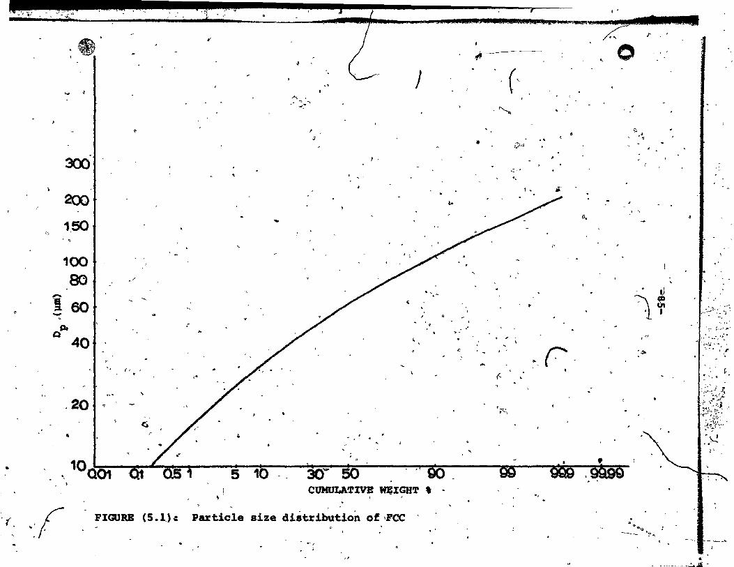
- " J
, . J .... ..,. ..,
~
, d
300 1 •
..
200
1,50 '::.
.. ~
100 80.1 .1' . ,
Î60 .: -~ l' ...
"
Q 40
.;
1 .:. ; .. "
.,., ...
20 t ?
G
• ,- t.
go 10Q01 Qi ..
\
,,' 10 30 .... 50 5
CUHOLA'1'IVE QIGH'l' , ;
'f. -:! , . Particle size distribution of,POC FIGURE (S .1,)-1
",
.1
t..
. " . . o
. '
il
•
...
(~
. "-..
v,<!j
~7 •
"
f-
'r";
~
.0
';'
!I.,
l'
r
"
f'
;-7 o ".
,
'" .~
, ,
\~ '1 J
." .~
~. >2I,..l1,
---- ~.>I,.
"
. ..-'
.:>:~'J .
:::~ ~~ .. ' ~ <
.. ~;.:~ ~:\."~ . .. ~. JI
1. ~ "!, .... -t .... ,r"l' ~ "~:;:"~ ';?~·t,: ~~{~~<l
.~.'-...!.
"
-= ._--_....:..~

_.
o
, .
,/ 1.
'. i •
/ 1
l '
•
, ..
.:
",,' / '
, /
/11' // .. 1
/ i
-86-
"
S.l,l. ~MaSS.Fl'ï'!f!f partic1es,, •
.Figur~ (;(5.2) ~hows frae~ional mas( fluxes for
partiele spEiciesi, with D • 225 and 150 }.lm. The procedure '1 p,
for c~lculating mass fluxes for eaeh species of .partia1es . ... .. is outlined i~ Se~ti~~ ,r). 'Fig~e (5. 3) ~hows the .
fractional ~ss fluxes for partie le speeies ~ith Dp • 96,
59.5 and 29/ }.lm, as well as the total partie1e mass flux ~ . .
1 ~b~ained. ~y aumming' the ,fractional ~I!fS ~:7luxes. The near-
flatness;of the total mass flux eurve,. Figure (5.3), is ~ "
due to the high weight fraetionof partieles' (95\) whQse -
5.3.'2. Mass Concentrat"ion iof . Partirles
,Figure (5,,4) shows the masa concentration of .
~acen4'inq and d~scendin~ partiel~s and the total ma.a - . , 'co~e~tration of 150 lJDl speeies particl~s.
/ "PiqUres (5.5 to 5.7) show the mass concentration ;"
'of partieles of .peeies whose Dp ( - 96,' 59.5 and 29 pm) < .opc.
1 The deduced 'initial partiele velocity .distribution wàs used \
to g8nerate the curves ahcnm in":ea~li of these ,Figures.
Figure (5.8) show.~he tota~,fractionai mas. co~eentration
Bach 01 the three curves ~
1
"
:-",
. ,
./ .. "
. .
. '
" . ~
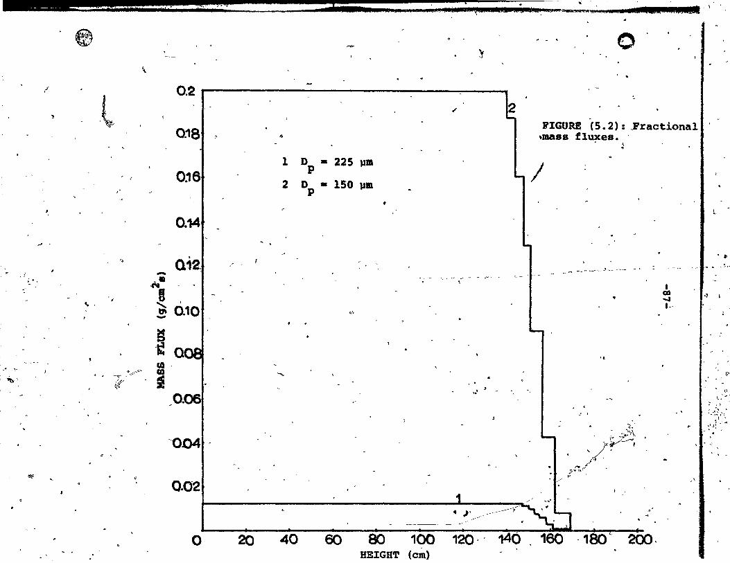
- '!y L j ;;; " .. , ~; li •• ; ~;st CIUe.ait U4, lb'''',_'~.",;"".· • 'BU lii%lidl' \ j'j 'r rlr J
1
,
,J' ,
" ; ..
.<
~\
~
~ ~1
\
~
l 0.2 -, ------.-.:=--------~-__,
0:\8
0:16
0.14
" Q12. -•• 1 -
,
0.10 ....
~ '~ QI CQ .
o -Ç' ca • < ~~.~' , se
,0.06
-004· <
0.02
o 20
"
1
2
'"
40
D - 225 lIJIl P
D - 150 lIm p
0'
•
,
60 80
<1'
.. '
. )'/ 100 120·' 140
HEIGHT (cm)
-.
o
"
FIGURE (5.2): .Fractional ,mass fluxes. .
1 ~
~ '--~ ......... ,) ,-~-'--
..
'(
~~. -
,/~~ .... ~-'
;-.... tt,;;/
t .,/" 1"
160 ,180 200·
1 QI) ~
l"
l
••
.,
(;>
\1
'" ::- >~.r , "\ ' '1_ ~ .. ~,~
l ' i'_,,,,, ~I ~;
• ,>
. \ ,

o
o
1
. . ~ .. Î~
Par~icles: 'II •
FCC, . .0' - 61 e'lil/s - t
l''\I~--------------- - - -,:- ___ ____ ..... ___ T::,o.:.;:t;;:àl. .... _:_
1.0
0:1
0.05 0.04
O.O~
002
i
l'
, . . " "
"}
..
, ...
,
\
" '
•
.. 0
:t ___ _
- \
-.
, •
..
,
~O~O~~'-40-··-·--~80-----~--~-1-eo---~~~,~,--~~~O~-.~~1 o HBl:GuT. (qm) "
" FJ:GORE (5.3)1 Total and fracti~n.l, .... ,- tlux ••• . ;" '.. ..,.
, . ,.,

*41.
0
"
""
"
",
'"
, '
'f
1
ao .. (\
..;
00
-""e 0·015 ........ ~.,
'" -~ ....
1 /
M 0.01 u . " 'fi)
fi)
i ~ tJ
, \ - -~- - .-.. - -- .. -
\ .... '~
,:ai .. ,
•
.. ,
-89-
, .
Total
LI
•
. . .... .
\
.'
, . ~ )
'.
,
, .
-
-
o 20 40 60 / 100 ~120 ,14Q. 1
.:,
fIGURE (5.4): ~ J
Mase CO:::.::: of .~eDdiD9 ~ de. Î ing -partiele. and the 1\,ota1 ma ... . eQnce~tratzaibr D ... • 150 J.lIIl -- ~ ._-~ :-., .: .
l,
"
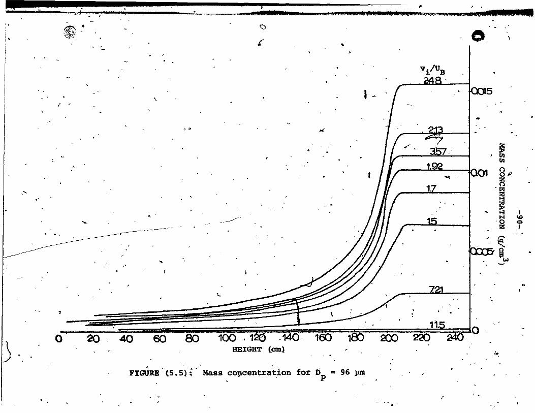
, . -1 _J .. 1.12 SU 6 ""4" ........ .. ........... "'_.' .. ;.& .... __ ... ,& ....... "",",1_''"'''''"",,*
1 •
i :~
"
'f'
.'
..
1
t5T-:\ • .*'~ .,~~>
,.
....
o
\
"
. ~ "
o '" #tl'
~
•
-~.
'"
~. . .
o ~ 40 60 80 1~. '12(5 .~~. 160 ~OO 200' 22011.5 a4d 10
HEIGBT (cm)
FIGURE' (S.S') i' Maaa cOllcentration for Dp = 96 l1lIl ."
" T
..
~ en 0 0"" ~ .~
... ! 1 H 'D
'0 0 l2: •
... ~ Qw .. -
..
J.o.
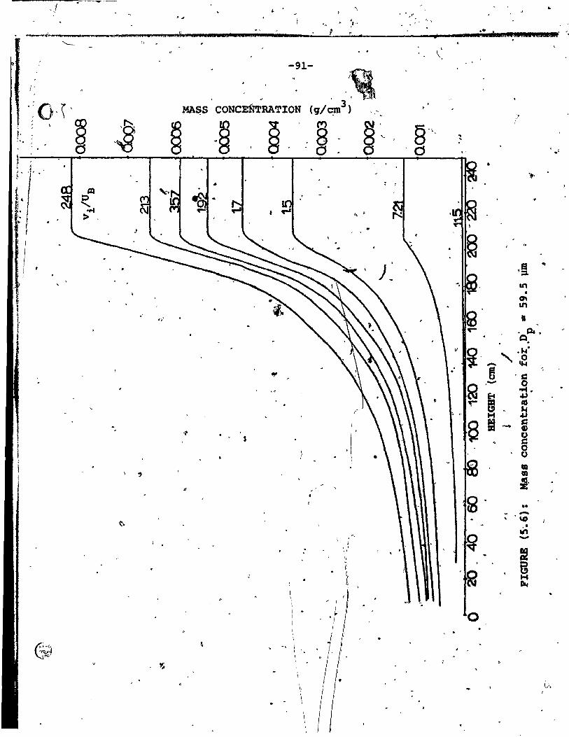
-1 '\ .. .. , 'J , . .- , " , > ,J' .' ! ,- ,lU Jil Maa ,.,,,.,.. "
f .... ' ... ... •• \1 ..... ::a:etUtid 1;1", 'QAt Bts ast .. .. iii U
'- ~
\
" . -91-
.\& " -:0,\ ' ~~S CONCEM'RATION (g/~3)" , -"
~ ~ '~ 1 ; § ~ -~ ~
M S'C, l' 8 .. ", :-
CS 0 0 CS ' , .' ~ • " .1
'r ... # ! 1
1%1 lJ ...... ....
10. '
1 >
1 }~ .~ .. .
1
an •
0\ &Il
~/~ fa n ~ . a..
Cl . " ~' ".~' - "" .' B 'c • - 0
Q .... "
& ~ • ,- lU ... !i
6 = c . - CI) "!' 0 J, C
0 0
ca ., ca
" i·
• ~
. •• ,. -, \0 , .
,~ ." -. ' ,
= " "
~ g 'Q H
II.
'. 1 .
0 1 1
1 • \ " 1
., G"1 '. r "~t' 1
',~ \ ,., ,
1 , t\ \,
1 \
1

~--_ ... ~. '5' ;;1 ... IW04!PJJU"4ii4Pt 2;;q2Jl",,~''''''''''''-'''''''''''''-
,
~
c~
" ri
1 .. <)
~. , ... •
0
" ,
"
, '.
'.
,
~ 't~}, . """'" '
• e
c.
j\
(,
-, .
~---
'~ " 0 . ~ , ..
(}J, , ,
, , "'. ..
I~ ,>
~
.. , , .
.. ....
'"
#
. ' '0 •
" ..
t ..
'l!
• a
"""7
co
...
•
"'-
1A
.",
~ , ' . •
:'. \
•
\'
•
, ~
•
(.,
.. , ..
,
~
'"
.<
ç
f'
o' ..
'"
'(
. '
.r.- -1 , o ,. "''-w0 """" '" C1:J5
c 1". -.",. 1,004
,~.~ (Il
'. ;-
8 ~
15 ,1 -~ 'CX)2 ~ ~ • ~ N
H " ,0 z , ~ "-B
7. . .001 _w
-:r
_~_. _ \ ro "". ..~ _~~~ _______ -"'---- J ___ ~ ______ ~ a~ • . •
"
-,
•
•
'"
"
•
,. , .
of'-" , " " ,
,'" Hf.).
). , .. ' -: .. .• ?oi(~~--': ~' .. ~/'l.fi.;1 1 .':~':.."_1 ... ~ ... _ " __ ~ " '~:~i~:~:. .. ~ ~~~,,,~~, ~ \~~~~
~~~\)r~ :-)
2b .(0 eO~,' 8J: 190 1~~~-:1~, 100 100 ,3X) 220 '·240 ~
~ \~ ... ,," JI. •
BBIGB'r. (Cil) • " " //
" • - " .. ~ss conc'êntrati;on for Dp - 2~ )lm J FIGURE (5.7): >-
., "".
'.' 0 J " .
.----...--'
-..
-------___ ... "'''''- ,~I_l:·f:t.. ~

_ -Hl '\ : . ' B. 1 _ ~...; , _,j U • _ .J.- ,, ______ • : .. , Vi.: AI'! J' el;$~iM"" ... ", .. ...-........ ... l • dl ar il ..... . '..
,
' .. ~
of!
•
, ..
•
"
~ 'l.
J
1 ,,1
;> ~ \
<:> :-
If:\ ~
" "'y
~ 1 ...
/' "
, , , .. '\....
1 D o~ 96 pm ':;;--" . P.- 1
0, " .
... ~,
il
" ~ o
(\"' fi' ~r f ~ - -
.~
, 6' 20
..
. '2 D '- 59.5 )III ~
P, . '. ~
j,. D _c; 29 pa 1 .. P
:;'. 0. ~ ! ,
! •
A~ •
~ ~ . 2 l:~ -
l'
! \ .
, 0 3. ~
.. ~/.
/'. , .~ 1.. ,: ~
"
" ", /, "
..
.~ .. .
. " ~
?"" ';
.,.
t> .... "'-:l;./-' ~ J
."1 -;:--,/
40 ~ .
FIGURE' (5.8):
~
rD
"
.___ 120' 340 . ~ BBIGB'f (cm) ~
"
160, 100 ~ 220
.Total .. mass concentrations fO~ ,Dp .. 96, 59.5 ~nd 29 pm ,<
"
J'
o .C17
.06
,05
~
;b4 r\ .... (Il'
Q 0
'Pi œ 1, 1 '\1)
~ w.. 'H' 1
~ i .02 -\Q
......... <..' r ",9
tA) -~
~",01 1
JL."O ••
, '" . ,
, ..
"0 ~ .
....;: ..
II:;
",~,t ...
1 ... > . . , .. ' ;. ,of:
, . '0' - ,.. . ~:
,.'
,- ~~~.~ :. ... ~, .. ~ ''I;f"t~' •
~{~~:i::: ~
c ~ \' .,
'<
~.
- __ .<l<
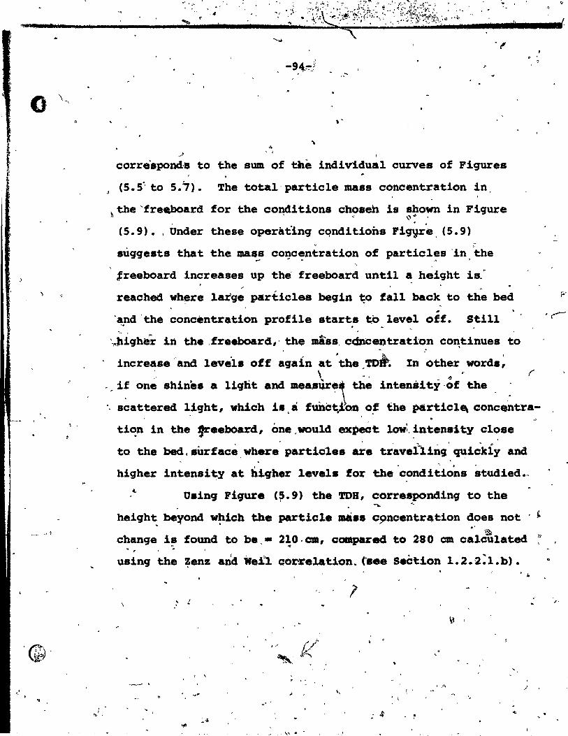
. "
~, ,
1 '" ,
. ..
" ",1 ) , 1
corre'spond'. ta the sum of tÀe individual ourve. of !'iqures
(5 .. 5" ta 5.7). The total-particle mass concentration in,
~the'fre~ard for the co~itions ch~seh ia ~90~ in Figure
(5.9). ,Under these operàtlnq cqnditions FiqVre, (5.9)
sùqgests that the masa
:réeboard increases up .
" ;
concen~ration of partieles 'in the .,. '" .~ ) ,
the' freeboard until a height ls." .
reachad wh~re large particle8 begin ~o fall back to the bed ..
'~~d 'the concentration profile starte ta level off. Still ~ .... , 1'" ~ ,
'-,.Jlighér in the ,freeboard,' the màss, cQncentration co~t.inues t.o
increase "and levèls off ~gain at. 'the _TD~~ In :ôther words~
. ' o
.' \ '. " 1" r , if one shines a liqbt. and measùre! the intensity,of the .
. .- s~attered light, whicb i. ,a funct.J:on o~ the ~rticlE\ con~~t:ra-. t.i~n in the !reeboard, one .would expeat low~. intensity close
•• \,..,~ .' .. p
ta the bed.8ûrface,Where partiel.s are traverling ~ickly and
higher intensity at hiqher levela for the 'conditions studied •.
Uainq Pi9ure (~.9) the TOS, corresponding to t.he
height be~ond which the partiel. .... c9ncentr4tion does not ~ .. ' Ill' 'al
change i!J founeS ta be. - 2;0. cm, compa.:e4 ta 280 cm calculated /'.7
• #'
usinq the ~enz and 1re!l correlation. (' •• e seètion 1.2.2:l.b). , ..
,/ Il ~: ~
. \ , ~ . ,..;;
" ~ . 1
.J
, .'
.. ~ ~
'"' .
,;'

e
·fII
Q14
-~ 012 B . ........
' •. /~ .. !
~. ~ ,'h",' lïC ".~, ~ 1·' , i(
8 ), "· .. 1'
'"
"
,0
"
\
....
.({ , .
;"~\'
).,-'
- ' ~,,':.!~ ~
;. ~ ,
:;'IL ~ -' ·1 ~ ~ '.(- ~~
",'
"J'
J'
" 20 4b
~ PlGURB (5.9),
;s,
è
, "
)
.~
-, , • 1 l
1
eo ~ "
? '
,""J
"
100 120" 140 BBIGH'l' '(çm)
.1
....
r '\
.. ' ..
160 18J 2(X)
~tal particl~mâS8 concentration in the'freeboard <,
'.'
(~
,~ ~
., .
,
220 240 _.
o
~
~, ."
1 ID Ut 1
1.,
'/ J
~
,'.
~,.,.,~
, ,
"
-;: • ~ I~ . -- ,;.'; ;:~'" ~ . " ,.. .... .".' ~
~~~->. -, i
~.'-;:)~,~.: - ,~~~~!:!--:;;~";"1.t;f, ~:~~':J
• ;~,.t t~~~~-~,
i':~: !~-,( " (-~-:
~
>,
t;
, *1% m ..il.
'" 4 !Ii •
o
"
"
•
, -.
"
, -96-
, l
,,'
5.4. Conclusion ~ 1\. .. '
A model for predicting the whole entra~nment curve
and the TOB has been dëveloped. This model is based on ~
an effective'bubble velocity dissipation function derived
from the theory of free jet dissipation. ana a velocity pro
file of ~jected par~icles_ deduced from-experimental measure-- - ~ \\ -
men~s of axial particle collection fo~mono-dispersed ballo-
tini beads. The volume of' eje~ted, particles at the bed ~
surface and ~ts variation vith bubble dlameter are the only , ,
• necessary experimental data requir~ by this mOdel.
Predictions'of TOU and maS8 flux at the surface 1 t ~ "
agree reasonably vith predictions of some.other'but by·no
1 Le Il '
means al1 other inv.stigators. The overall shapé8 of fractiona1 l ,~ •
and total partielè flux •• appear to be reasonab1e. Entrain-
ment rates above the TOS lie within the scatter of results
obtained fram CompetiDg correlàtioD.. However, these -
entrainment repults (above the ~H) are larger than measured
recent1y (e.g_ by Large et al). The reaSODS for this
diacrepancy may he due te the followinq limitations in the
entrainment moèhll,1 , ,
(a) The exiatence of a max~'aolids concentration above ,.. - .. ~, .. - ~~ ;j .. . . ,
which particles in the freeboard will choke aad fall baçk
to' the bec! surface has not ~en éonsidered.
,

• ,0
o
•
.. f ~ 1 r -97- , ..
! (b)
~
Wall effe~ts in the freeboard and reciroulation of , ,
solids near the wall are-neglected •
", (c) In practice, ·th~re will be a distribution of bubble
sizes at the bed sUrface. . ,
(d) particlé.segre9at!~n effects in the ~ itsel~ ~ve
been ignOl"ed. -
Detailed con.ideratio~ of'tbe above points is
presented in Chapter (6).
\
"
'.
,. -\
'--(1' ...
"
" .... ~ . 11 ~ \ ~ .... ,J ,. ~(
~. ~! J
'<-
l .0
,/ ,
\
.. 1) \
<.. l.J_

• ~_~l~ __________________________ _
o
"
','
" " '",-
"
~ -98-
.'
DISCUSSIONS AND SUGGESTIONS FOR FUTURE WORK
6.1. ~e~tical Pneumatic Con~eying .. 6.1.1. \ Introduction
.. 1 . /
In vertical pneumatic tran the part;cles are e ~
. often "carJ:ied 'ri.ras a~ apparently evenly ispersed suspension
with low volumetrie concentration (generally le,s than S,') • , .
If-" the carrying g&S velocity ia gradually'reduced at the . ,
samè mas{ flow rate o~ solids, the in-line soli4s concentration ci
increases. A poin~ will b$ reached where the càrrying ga8. ,. '\ . ,
velocity is insufficient to support the particle8 as a uni-
form sU8penaion~ Thé entire suspension collapaes and 1s
then transported up the coltDÎtn 'in sluq flow. The choking 1
velocity is defined as the velocity at which transition
fram upfl~ of solids ~s a thin suspe~ion- (often referred
-to as lean phase flow) to ~lugging flow (sometim~s referred
to Âs dense-phase flow) occurs.l
Th~ mass flow T~te of S~lids. 1 '",;;
·at the point of chokinq is considered the maximuni aafe j 1
sOli~ transport per unit flow of gas in vertic,ali pneumatic
transport (Stemerding (53}). Several ~tudies haJe been • 1
,. 1
carried out to predict the choking velocity in èonnection

.. .,.."
•
, . AL tl4 A • Q • ..seàd = eJi li.'"
o
~ W
-99-
/
/ with optimum design of vertical conveying units. A cri- .-
/
tieal review of sorne of the ~ore reeent studies ~s presenied
Lh~r,e.
(. j
'\
\;.
6 .1. 2~. Zenz and Othmer
:') Zenz and Ojmmer (54) reported that saltation (for .r ,
flow in horizontal pipes) and ehoklng (for flow in vertical
pipes) velocitiea are almost equal -for ~iform-size particles,
while mixed-size materials give s'a.ltation velocities three ,.... ,0
t~" six times as great as the corresponding/ ch.ok~ng veloei ties.
They recommended the use of the geometrie'wèigh~-mean partie le , .
diameter to caleulate the ehokinq velocity in verticaL convey-~ , .
i' ing of material of non-unifo,rm par'ticle size when U > Ut of" ,
the larg8st partieles. Results oA chokinq for 18 runs were
correlated graphically by piotting (G/UPf) vs. ,u2/9DpP~ ,
where G· - superficial mass flowof solids at chokinq, Ib/ft2s. , .
This, correlation is of doubtful value as it does not take
into aceount ~e terminal'veloeity of the partieles. F~ther-
, 2 2 ' . more,t?e quantity U /g~~ps i8 ~ot dimensionless.
\
6.1.3. Leunq, Wiles, and Nicklin . ,
Leung et,al (5S)<deri~ a correlation to predict
1 ehoking flow rates of solids in vertieal pneumatic convey-
inq by a.s~ng:
/
, ,
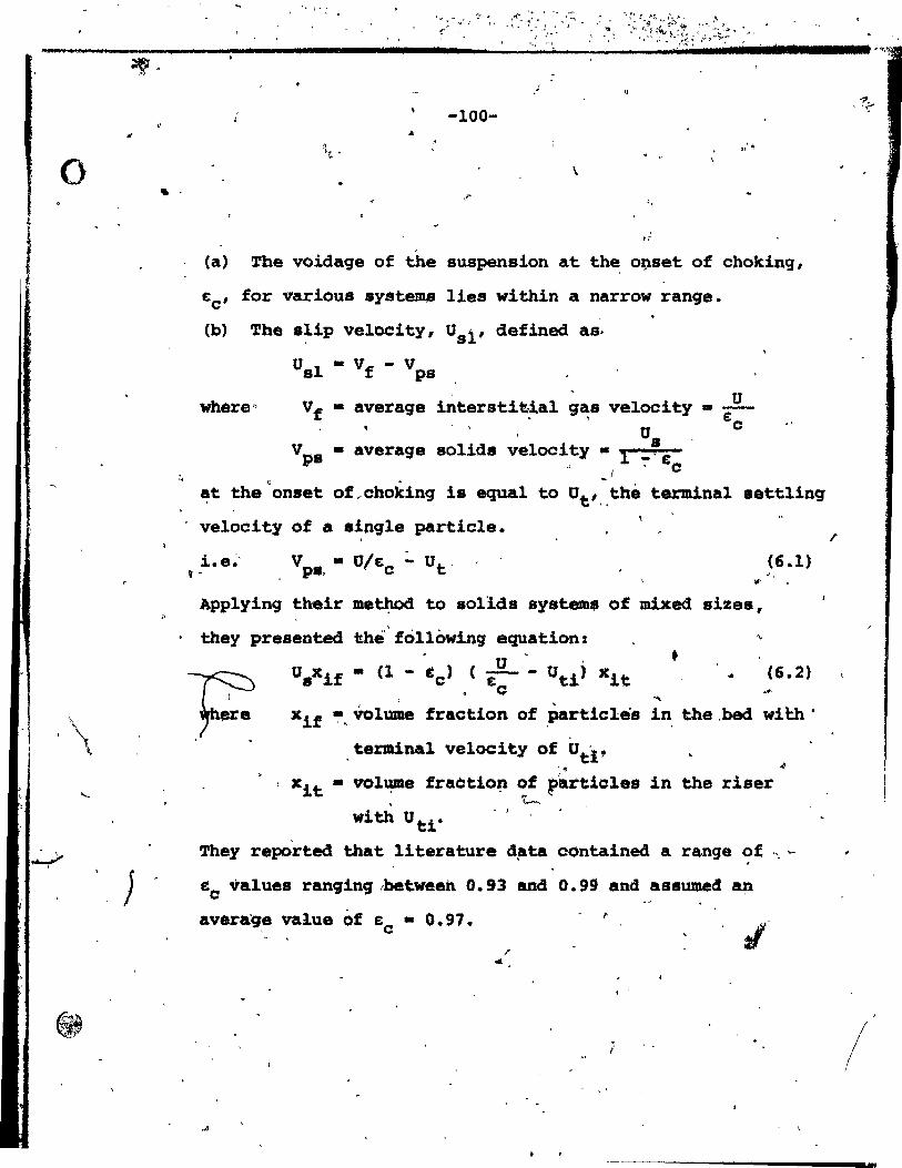
.... * lA
o
\
J
. -
Il
J
-100-
III'''' . .. \
le
(a) The voidage of the suspension at the o~set of choking,
~e' for various systems lies within a narrow range.
(b) The slip veloeity, Usi' defined as,
Usl - Vf - Vps u where" Vf - average interstit~al g~s veloeity • ---E:e U
vps - average solids velocity • 1 _~& " 'e
c. _1
at the onset of ,ehoking is equa.l to Ut'. ,thë terminal settling
veloeity of a single partiele.
i.e~· ~ 2
v • U/~ :. Ut. pa, e
Applying their .e~ to aollda system. of mixed sizes,
(6.1)
. they preaented itht{ following equation: U .
Usxif • (1 - te) (~- Uti) Q
• • (6.2)
,
xif~. Volume fraction of partieles in the.bed wi~h'
,terminal velocity of Utl , .~
xit • vol~e fraètio~ ~f partiel es in the riser , ;".-.
with Utr - )
They reported that literature d~ta contained a range ~f " ~
&e values rangingrbetween 0.93 and 0.99 and assumed a~
average value of &0 - 0.91. ~
,.
.A - >
2 ,. 2~.,
i
/
..
o
, -rll J 1&1 1 ~;
, -101-
" 6.1.4. Nakamura and Capes /:~'rrr.
Na:kam\U~ and C~pes (56), ·developed. two modela fOl:
vertical pneumatic conveying, a uniform flow model at hi!h
gas velocities and an annular flow model near~ t~e particle
terminal velocity. 80th models indicate that ~he slip
_'velocity may exceed the particle terminal veloQity unde+
certain condit~ons, in agreement with experimental measure
ments (Capes and Nakamura (57». '() Several parameters, (e.g .•
voidage, 'fl.uid shear stress, ~nd other 'constants) must be
specified before the uni~o~ ·fl.,Ow mOdel can be u~ed. No \ •• 1
, . . simpl~ analytical solution was,tound !or the annular flow l'If· ,. • •• _ ~
mQdel,' but a numerical'solutioq was.'rèported to be possible. ~ 0 (J" .,
In a rec~nt paper by the .~e~wdrke+.s (58) ~reating vertical - .' .
pneumatic conveying-of binary Particle mixtures, they " ~ "
studied the'effect of particle ~nteraction in order to " '
explain more precisely the 'behaviaur o~non-unifOrmly size~
particles in a vertical conveying line. They noted that A
part~cle collisions slow Jdown the finer particles and 1
1 1
accelerate coarserf, ones eadinq to greater fines concentrations 1
o 1
and fewer,coarse partie es in the-col~ than'would oeeur if
the~e we~ collisio 8. Their model predicts the ob
greater accumùlation· f co~rse, particles in the'lin, , '''.
1
...
,
rved
1 , '""
1 <1

o . '
. ./
.,
-------_._-~_ .. ,
-102-
• '.
" .
gas velooity is decreased and a decreàse in cho&ing velo
city as the concentration of finer particles increases.
6.1.5.' Knowlton and Bachovchin
Knowlton and Bachovchin (59) carried out experi
ments on the effect of high ..(Jas densities o'n pneumat.ic \ .
l
conveying parameters. They presented the following corr~-.. lat10nt o
,. Cch P. ,.0.347 W D'" 6.214 fi 0.246 - • 9. 07 .( ~ ) ( .ch Il ) ( :R. ).
{g Dp Pf . --.J Pf *. Dt .. . . j
whet'e Uch~ phoking ~elocity, ft/s.
Wch • solid mass ~lUx,at chok~n9, lb/ft2 ••
The above correlation was developed fram data obtained ueing - ~ " '. , .. . 8ide~ite ore and lignite, havinq approximate bulk densities : . .. . . of 2.4 and 0.75 g/cm3; respeQtively. Bath were vide-particle-
v u
size range ma~erials.
6 .. 1 • .6. Resulta and Discu8sion •. .
,Three of the above correlations (Zenz and Ot,bmer,
Leung et al, and Knôwlton .and Bachovchin) are applied to ., . . . 1 two specifie example. below, in order to illustrate'the
.' , .r"
signific~nce of pneumatic, transport of 'aolid~ Ion èntra,i~ent • • ", '1 \
•• '.
0,
'f
>.
1 r

o -,'
.'
''':103-
of particles in'fluidizèd beds.
.. ,
The Nakamura
modela are not suitable for the present case.
(a) Operating conditions:
\
~s " Fee with size distribution given in Figure (5.1) Particles:
U • 6'1 cm/a
U f ~ 0.4 cm/s .Dl
Dpe ~ 120 l1IIl
(b) Operating cond~tion8:
l . 1
, .. Particles: sàn4 vith size distribu~ion:
Particle Oiameter:
Weight Fraction: ,
U •. 30
"
o >250>0 >150>D' >88>0 >53>0 >45>0 >37>D ~ p Pi P P' P P
1
0.63 40.66 46.26 9~48 1 .. 15 0.69 '1.12
cm/a 0'
Umf ~ 6 cm/a 1
Dpe III 6S ).lm
,.
'",
, .
Table (6.1) shows a comp&r~aon of superficial ~olids'
mass flow rates obtained by'different correlations ~ogether l ,--~' ,
vith results ~bta~ned fr~ equa~on (5.3), i.e. ~ntrai~~nt ~tates predicted by the bubble ~e1 ignoring Any saturation
(\ ~
~ -
or chokinq considerations. It ds clear that the mas, flow rate
,of solid8 predlcted by the entrainment mcael lies withln the Q
~ t
J'
, , '-, ,
" . . ,
'II

""'.S1 tU, 1 _ _
o '"
C~
• ,-
.. ..
/ /
f' l' - 1$ b • , G Êi 1 JI d a:UI2 b k !ID" ".',
,,'
superfi~ia1 S01id Mass Flux Rates (kg/m2s)
(a) For,Fee particles at U .~0.61 mIs
Present Zenz and work Othmer*
35.0' '0.8 5:4.3
Wi1es, and Nick1in €c=~~9~ ~c-0.997
p 21.6 1.0
(b) For sand partic1es at U - 0.30 mis
Leunq,' Wiles., and ~ick1j.n
1
" Know1ton ,and, \
Bachovchin* '\ " ,\ 62.0 ,\/Y
Present Work
Zenz and Othmer* " e; -0.97 e; -0.997 • c __ c ____ __
1.5 0.02 , 5.0 0.4
l,
, . \.
* The qeaœetric ~eiqht me~n ~rticle di~ter was ~~ed ~, '
here to ca1cu1ate the .uperf~cia1 801id mas. f10w rates. ,.
-1' 6 • . . ,.
'C---. ,
\ . . •• cP ..
." b
. , . .. -;
'1 (
...

--,. - \
, \
-,' t;
-105-, .., ..
l> l' -" . .... "1 . 0
~ . I
t, / ; ~
scatter of resul.ts predi,cted I:;>y ,~h ChO~tf9 ~rre1atio~s .~,
Inde,ed 'resu~ ts O.f .~e entr~irimen~ el/re: èonsis-tentl~ ~igher than choking1Predict~ons of the ~enz'an Othmer or Leung et al
1 .. - , , ',' -
(with € = 0.997) correlatio'ns •. : AlthOP9h predictions differing • ~ • 1- r. 1
0, " by at 1east an order of ma..sni tFe a:re e~~ily obtained from - 1 1 "
the ~hoking corr~latiops, they, nevertheless, show· that under o , ( • • ~ ,,---J :", ' certain,Q~ratin~ condit~ons choking i~ §pproached. In these' a
P',
& ' cases, it seems likely that ~e mass flow will be limited by
, chokinq ànd that the amount "of SQlid particles ent:r::~ined above
r Q
" thë TOH will no t' eXceed the chok!ng' conditi6n. It is there-• " li. .' "-
fore recommende4 th~t 'the mass fiux of particies' und~r choking # " • •
. condi tipns shou,ld be calcl,,1laired ang the value, $hquld' b~ used ta w
. ' : '" estimate entrain:plent above the TaD if the bQbble model predicts
.:1[' c~ ..
a higher entraiN!lent.' Th,is .helfs -to explain Why the entrainment . , 'Ii' model,tends ta predict valuè~ whicn are too high i~ sorne cases
\
, as shown in Chapter, (5J. Unfortunately, a value of tc is an
\ ? n )
.( ~portaPt parameter i~ predictlng pneuma~ic conveying under
'. choking cbndi tions and must be measured -for each èystem.< ü ,
• Capes and Nakamura t57) noted that the me~sured
-particle slip.velocity wasDgreater than .the te~inal ve~o~
L • ,'~ - , of ~
çity (see Section '6.1.3.). (The explanatiôn proposed for
this i,nvol;'ed par_~icle friction , '.J '. -r • /-,/
recircl,ll'ation.. Boi~ phenomena ----V . ,'... .
,
at the wall an~particle p ,
have been'ignored in the
, '

J '1
.'
. ' " "
~) -. ~
, ..
> • .
.
• lb
* .
1Hl1
'" .
·-l06-~
,
preéent work~, At low gas velocities approaehinq the . . \
choking req " it has been observed (e.g~ see Van Breugel ~ Q ~
et al C60» hjlt some par.ticlel$ remain stationary and even
flow downwar I..léar the wall. . Bath parti~lè-wall friction. ,
and particle reèi;culation effects lead to lower average· l "
pa~ticle veloclty apd hence qreatèr slip velooities thah . . v predicted by Squation (EJ;-.l).
, . Partiélè-wall friction losses were eorrelated,.by
"
. '
dUi ••• ··
, ,
•
\. Capes anQ Nakamur a ,( 57 ) 1:ly ~e equa tion.;
- J 'fp
• 0.'206' (1 (1 _. e'» -1. 2~, .. . l (6.4)
where S - volum~trie 'flow rate of solids, 'ft~jk. e - voidage . ,
"
They also reported that negative partiele-wa~ frlêtion
may resùl t if the gas '(eIoei ty is near the termi~al veloei ty .' ,\) '.
( / ~ . "~ue to rtverse p~rtiele flow at 'the wall.
, . ' •
6.3., . Partiel! Seqre9ation--trl', the Bed , ~ , ,::!'-.,.' t •
. In othe pres~~ WO:~' r'i ha~:e~ ass~ed that, ~ .
the parti~les e~ected Into the.fr,eboard are representative
œ those iJlo~e b~d ai A who,le in view of the fac.t that ,the '" r ~ \. ".. ,
ejec~ed partieles originate:primarlly from"bubble wakes as , ..
Aèmonstrated rn ~hapter (2). While this'a~sumption ~eém8 '1 ..
reasonable under 1PO~1fond1tion8, it shb~d be ~i~t~ oht
/~at Rowe et al found thin la~ers of segregated partiples' ',' .. + ~
,
/ , .
, \
"
•

o (
f, .
'"
, . . -
j.
11
'.
y
)
•
. '
, .
. -107- . ,
, ~ , ) ,
• /, ,
" . \ ..... ' , ..
.' both at the bed surface and at the distributor. Bence ..
,
~he ejeeted partieles ~ght ~ave a somewhat lower fraction, "' both of the finest (or lightest) and of the coarsest •
(or heaviest) partieles for a poWder with a broad siz~ -, (or dénsity) distribution and this miqht cause some dèvia-
" . ., tion fr~ the model.' For.other work on segregation in
'. ,t.. . " 'agcireqative fiuidizad be<la, see Gibilaro and Rove (61), ,
Chen and Reairns (62) and Shannon (63). )1
1 •
6.4. Bubble Size Distribution 1 \
In app~rinq\~be entrai riment model ip the present ( . . \ .
work, 'bubbles ~ri~in9 at the be~ surface bave been.assumed
to he ot un1to~·.~ze. In actual fact, bubble distributions' - - • 'j ~ ' • ....,. • • •
• " a,x:e nevët.!cOmpletely uniform" and th~ di.~r.iO~- cff . sizes ..
'. . may be broad, especial:ly- in deep bec:l •. eont~ininq re1ativ:~ly
. " eoar~e particles. Bubble size distributions have been repre-
l' " ~ ,
sènted by qaJllDa and loq-normal di8~ibut.ion. (64), 'but . . - /1. .
general.correlat~oDs for di,tribu~io~~pa»ameter~ '(loga-. \.",
rithmic stanaard deviation, etc.) are not available. An \ .
\ ~ .... ~
'alternative approach lS ta u •• a c~puter simulation to ' " ~ , ~ v
predict the ~ubble distribution at the bed surface (65;66), , • Q
,;,& '
but 'this .. wa. beyond the scopa of ~ p~esent project. -(_
Certa+nl~ i ~ ,is .a 8SD!1'll step to aJ.low for bubbJ,es of different '
\,\ /.\ '.
,,;4 '1 • f,
·1 . ~. >
... 'r!'"
. " f'
•
.' , ,
w;; uta:;;] 1
o
,~~ ..
•
..
"J
.-
, "
-lOS-
r,' . . ", ~ -/ ','
" "'" " ;,' ~, ,";!" ... ;-'t<' 7" , -~, -.' r ''1
_ w_
• sizes in the entrainment model once reliable in~rmat~on
. '
reqardinq the Bize distribution asav~ilable.
6.5. Effeet of Partiele Interactions' in the Freebôa~d
,,'" ..
In the pr~sent wor~, partiele trajeetories have been .l'
ealculated ignoring particle-partiele interactions. The
volume,coneentrâtio~ of the di4utë phase in the freeboard can ~ .1'" --
he est~ted fram Chapter, (5), Figure' (5.9), "to' be • 1.5' •
c~ose ta. the bed _urfaee:and 6'.near the TOR for Fee part~9les • ~ ..t •
flu~aized by ai~ at'u - 61 ~s •. ~is c~nge in vol~etric , ,
conéentration will cause the density~and v1scosity of the" sus-. .;
pension to vary., Rùtqers (67), ha~ cor~elabed th~ relative
viscos1ty'of .uspension~ of rigid~spher~s ~n Newtonlan liquids .. " . '. '
~ith vol~etric ,concentration of s~speri.ion.' From'his work • it may De eon~luded that for a given suspension the relative'
c
'. viscosity increases lin.arl.y with volumetrJ.e eoncentratiop .. , .
up ta a value of 14' of the latter. The d1lute phase density , . ~
will also increase w~th concentration. The impliCa-tion or
thisvariation of gae (dilut. pha •• ) dènsity 4nd v.lscosity in .. ~ , r l'
the fraeboard ragion of a flu~dized bed would be to .increase v
th. drag ek;PU'iC!nceâ by'.the partiel.s. ~eu the bed 'turfaee. j ", '" 9> /b ~ • ~
:"the drag acta to .lov àoWn the partieles, whereas once their <,. 1< ~ ..;-
velocity re.,ches the- superf"J.cJ.al cias velocity drag'forces ,p-,
act to carry the particles hiqher. a-~nc, it is not clear <lI-
l ' .. ..
. .)
"'-• " . . ~" ,., "'",

o -109-
:.""
---------~ i'''' ~ ---------
.. what the ove~all effect of par~!cle interaction woùld be.
. ,
A r~finement of the present model would take into açcount . /Î
pa~ticle-partiçle interactions through the viscosity and
density of thé qas used in calculatinq the ~raq forces. "
~ This was beyond the scope o~ the present project • .
6.6. Conclusion and Suggestions 'fo~ Further Work
. A simple and mec~istic model has been proposed
and tested for the .. pre4ictions of transport disenqaqinq . , r
hèiqhts and en~aihment ~ates ~r~fluidized beds. The . '
" advantaqe of this model lover qthermodels la that it requlres
only a few easily performed flux measurements at the bed \
·s,Urface ·and that i t is based on the actual mechan'ism of
e~tralnment. ,.
'\
A more refined model can clearly be Aaopted ~or
industrial-sca~e fluidizéd beds às more entrainment'data
are obtained for various partiele sizes and den.iti~8 to
peX'}llit a more accurate and g.eneralized bubb!'e velocity
dissipation functio~. lmprovèd means of accounting for "
side-wall ~~fects, PllX'tici, interact16ns, . partiele recircu-. ,
1«t1on ·and partie le ~eqreqation in the b~ proper are required
tGqetl).er with imprpv8d 1I\o4'è1s for predictinq the size and ' 1 •
velocfty d~tribution ofobUbbles arrivinq at the bed surface.
. ,.. ), ,
'.
<
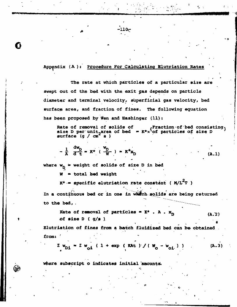
(;
: <
" ~
'. ~>" '" . ... ,. ~ . :""(; < • "" . : ,;;: ,. -' . .. ts 11
~ . . " fr .m J1l
• -110..:-
," .'
App,ndix "(.A ) : Procedure For Calculatinq Blutriation Rates
The rate at whieh partie1es of a partieular size are
swept out of the bed with the exit gas dep~n~s on partiele •
diameter and ter.minal velocity! superficial ga8 velocity, bed
surfae~ area, and fraction of fines. The following equation
has been proposed by Wen and BaBhinger (11):
J
1 1 1111
~\lt
Rate of removal of solids of siz~ D per'unit2a;ea of bed surface (g 1 cm s)
{Fraction·of-bed consisting} - K*x of partieles of size D
dwO wo ,.
1 ,
K*x., - A a-t - K* ( -) • (A.l) W .
where w .. weight of solide-of size D in béd D . ~ .. W • total })ad weight
K*·. specifie elutriation rate Con.tÂnt ( MVL2T ) ..
In a eont(n'hous bed or in one i~ -W~h---~i~d8< are being returned -. to the bed, .
Rate of removal of partieles • lt* • A • XD of size D ( 'lI.- l
f <,
Elutriation of fines from ~ batch fluidized bed ean be obtained . ,
from: ( ...
(A.3)
wbere subs~ript 0 indicate' initial 'amoun~&
• J
-".
~

o
.. . ,
..
( J l J •• ... ..I8 •• S :!II. e"7l
-111-
, '.
The fo1lowing procedure~as been used here tO'compute
e1utriation rates from the correlations discussed:
(a) Ca1cu1ate the maximum size of particle likely to ha carried
over at a given superfic~al gas veloclty, fram the ratio
Co / Re -
Read the
Bence:
CO'rresponding "li D' _ f_
pc Pf.~t·
. ..
, '
Ret from a plot of coiRe ",versus Re
(
(b) Only particles small~r' than this size can he c~ied out '.
for a suffici~ntly ta~l column. ,. For particles smaîler taan. l ,
ope divide, the siev! analysia into conveJiient. fractions, ...
and calculate:·
Co Re2 • 4. (i P2 - Pt2)Pf
3 • lit '
for each fraction. The corr,.po~in9 Ret 1s read trom ~
plot'Of CDRe2 V~8qS,Ret. Bence calê~lat. Ut for e~ch. si~e , fraction:
i.d.
Cc) ~aluate the .pealfic elutriation rat~~con8tant K* fram i:' ',..,.. .... .Je
Yàgi and ADchi (10) orWen and ~aabinger (l~) for each aize
fraction ...
.. , .
(JI
. ,

• : *i'" L .,1
o
•
-112- .
(d) For batch operation use equation(A.l) above to calculate
elutriation raees. For continuous operation with total re-\.
1
.cyc1e of elutriated fines use equation(A.2) above.
~
...
"
.....
.. ,
(,
;.-"
1
1
" .-
j
.r. 1
./. J 1
1 1 , 1 1
j 1 1 1
1 'b ,. f
1
, ...
1..
:.
'r .
... ,- 1
, "
1 . ,
l i ' ! • ~-
~,
,l'
",
~ t "
• 1
'.
-, .'
,',
..
• r,
• ,!2 -
• 1)
119 IL RI '''-'ft
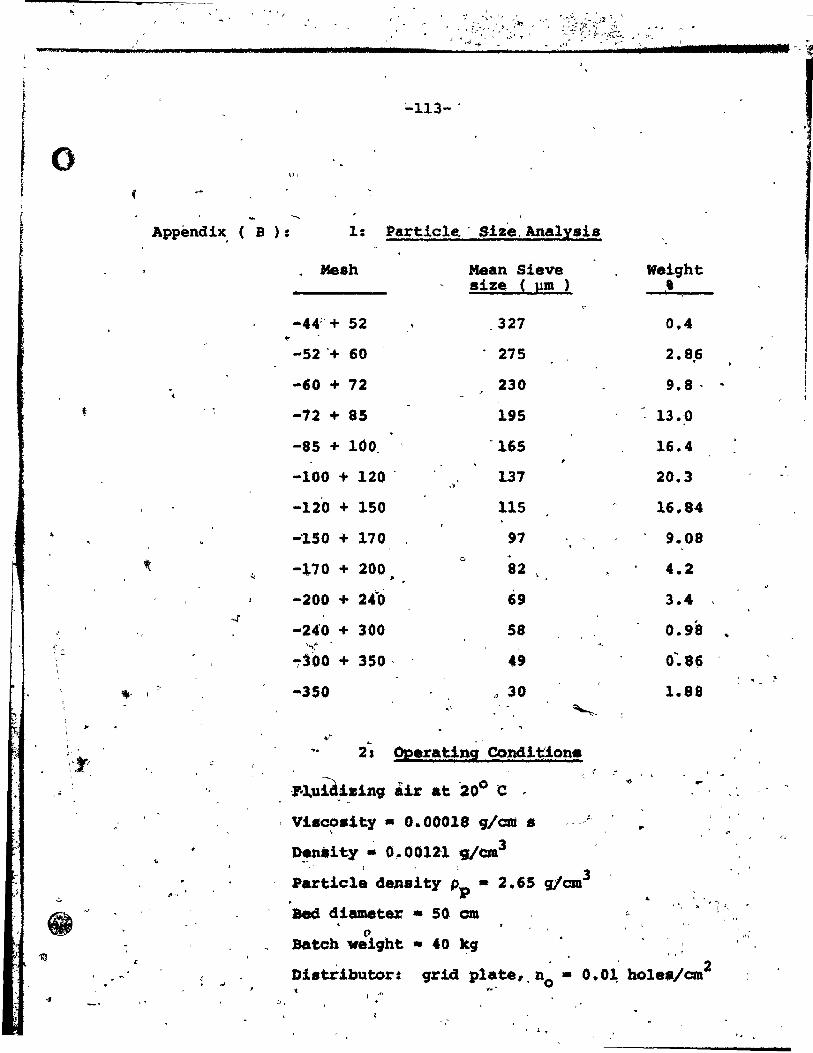
1.
~113- .
0 q.
4 , r -..
1 APPEmdix. ( B ): 1: Partiale. - Bize, Analysis
Meah Mean Sieve Weight size ( }lm ) • ,
-44;- + 52 327 0.4 ~
-52 '+ 60 275 2.8.6
-60 + 72 230 9.8 . .. "
t -72 + 85 195 13.-0
-85 + 100 - '165 16.4 ,
-100 + 120 ' 137 20.3 ,>
-120 + 150 115 16,.84
-'ISO + 170 97 9.08
~ 0
-~70 + 200 82 4.2 " 1>
-200 + 2.fa ,
69 3.4 -f .
,f -24'0 + 300 58 0.98 , 1
" - "',~ , ,
~~OO + 350· 49 O:8~ , ~
- -" -350 ,J 30 1.88 ,.- 1
," '-( , " . , ( ,," . '
l' '" 2s peeratiPi Condl~ion. "rI ê , , ,r ."
7-1uid~zln9 air at 200 c "" ~
, . . Visc08ity • 0.00018 ~/cm 8 .' , ..
-. D~.ity ~ O~OOlZ1 9/cœ3
"
. ; "'" P~ticl~ deJtslty ~p - 2.65 gJaa3
'" 4 ' . "
. -, . - 8eél diameter - 50 cm )0 l.l,
<
() ,"
'lf:ll Batch weight • 40 ~g , , .
0.01 hole./om2 , Di.tributor: grid platet, no • . '" , .. ., t .' :', .
, .. , ,
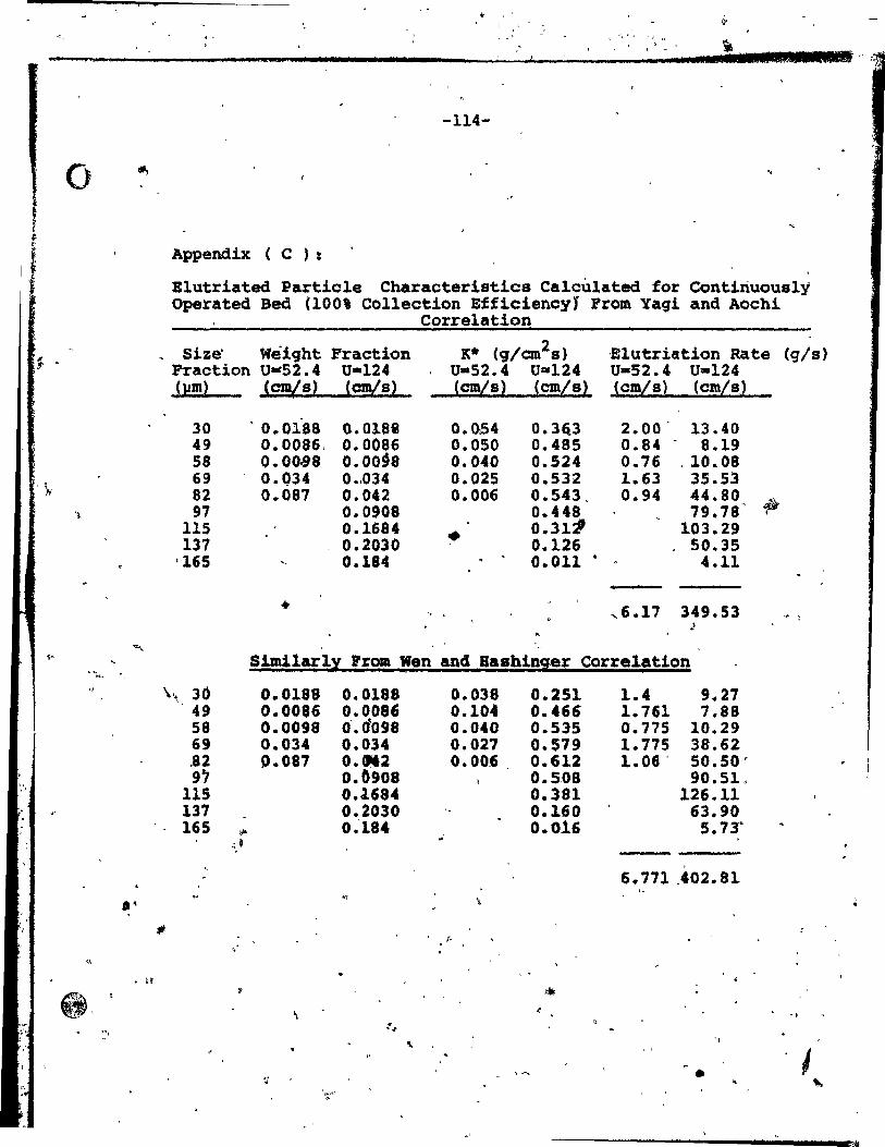
el. : MR _
f .
'),.
.~.
-1;-
-
'" "
~". . ~,
•
,
'"
.. , '. l "
'," r • .,
= " la
_blA. Il Si aiR IIlI ... " ;',
-114-
Appendix ( c ):
Elutriated Partie le Charaeteristies Caleulated for Contiriuously Operated Bed (100% Collection EfficiencyJ From Yaqi and Aoehi
Correlation
Size' Wèiqht Fraction K* (g/cm2s) 'Elutriation Rate (g/s) Fraction U-52.4 U-124 U-52.4 U=-124 U-52.4- U-124 (pm) Ccmts ) (cmVs) (cm/s) (cm/s) (cm/s) (cm/s)
30 ' 0.0188 0..0188 0.0t54 0.3Ei3 2.00' 13.40 49 0.0086, 0.0086 0.050 0.485 0.84 8.19 58 0.00.98 0.00§8 0.040 0.524 0.76 . 10.08 69 0.Q34 0 •. 034 0.025 0.532 1 .. 63 35.53 82 0.087 0.042 0.006 0.543. 0.94 .f4.80 97 0.0908 0.448 79.78'
.,. 115 0.1684
~ 0.311' 103.29
137 0.2030 0.126 50.35 '165 0.184 0.011 • 4.11
.. ,6.17 349.53 ' . " , )
Simi1arlI Pram Wen and Bashini!r Correlation
\\ 30 0.0188 0.0188 0.038 0.251 1.4 9.27 49 0.0086 0.0086 0.104 0.466 1.761 7.88 58 0.0098 O'.d098 0.040 0.535 0.775 10.29 69 0.034 0.034 0.027 0.579 1.775 38.62 ,82 0.087 0.0162 0.00.6 0.612 1.0e· 50.50' 9" 0.b908 0.5-08 90.510
115 0.1684 0.381 126.11 137 0.2030 0.160 63.90 165 1/1' 0.'184 0.016 5.73"
~, t '"
6.771.402.81 ~f ..
;k {.
"
• tf m '-.
\ '" ., . '1-
" "-
;~ • 1 ~.
" ~ '~t·
;ilI
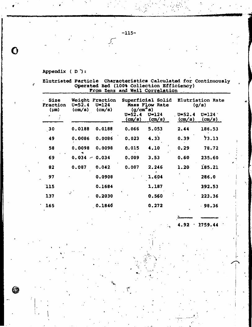
1f;eJl'Qj A44 w
o
'. , -(. :; >,..
,', ",-,--
FI
. ,
" , . .::,\" _ 1 .... ( "
~ ~ ,) ...;.. \ f ; t:
,. 1 ' .. ~.L ... , -115-
. ,-
Appendix ( 0 ") :
Elutriated Particle Characteristics Calculatea for Continuously Operated Bed (100' Collection Efficiency)
, Size Fraction
(J.1m)
30
49
58
69
82
97
'115
137
165
'\ '
From Zenz and Weil Correlation
Wei9ht Fraction U-.52.4 U-124 (cm/s) (cm/s)
0.0188 0.0188
0.0086 0.0086
0.0098 0.0098
0.034 ~ 0.034
0.087 0.042
0.0908
0.1684-
0.2030
,0.1846
Superficial Solid Mass F~OW Rate
(g/cm a) U-52.4 U-124 (cm/s) (cm/s)
0.066
0.023
0.015
0.009
0.007
..
5.053
4.33
4.10
3.53
2.246
1.6"04
1.187
0.560
0.272
-"
E1utriation Rate (g/s)
_ U*S2. 4 (cm/s)
2.44
0~39
0.29
0.60
1.20
4.92
\ , j 1
~----, --------- - \
U-124 c
(cm/s)
186.53 . 73.13
78.72
235.60
185.21
286.0
3,92.53
223.36
98.36
1:759.44
;
1
-1
,. 1
1 1
i
~ 1
1
, ,
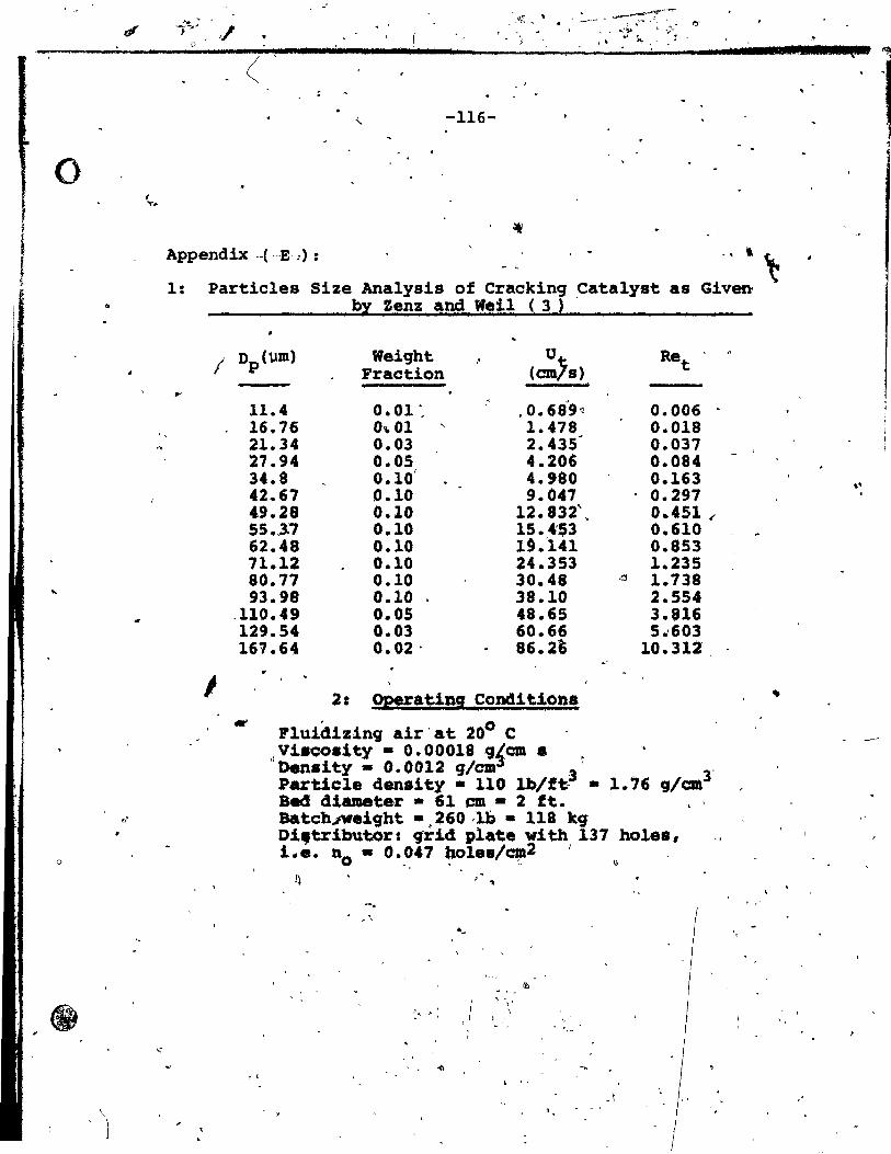
o
..
f ......
,llt~ \
" ! D •• bd j a
(
-116-
Appendix ._( --E 1) : ., l ~
1:
, ,
Partic1es Size Ana1ysis of Cracking Cata1yst as Given by Zenz !nd Weil (3) .
1
11.4 16.76 21.34 27.94 34.8 42.67 49.28 55.,3.7 62.48 71.12 80.77 93.98
.110.49 129.54 167.64
Weiqht Fraction
0.01 " 0 .. 01 ' 0.03 0.05 0.10' 0.10 0.10 0.10 0.10 0.10 0.10 0.10 0.05 0.03 0.02 .
• 0.68'9;] 1.478 2.435· 4.206 4.980 9.047
12.832' . 15.4'$3 19.141 24.353 30.48 38.10 48.65 60.66 86. 2"~
2: Opera ting Candi tio.,.
Pluidizing air'at 200 C dVlac08J,ty - 0.00018 9{ca. .
Re " t
0.006 0.018 0.037 0.084 0.163 0.297 0 .. 451 l'
0.610 0.853 1.235
a 1.138 2.554 3.816 5 .. 603
10.312
1)enaity - 0.0012 'l/cm , ' Partie le density • 110 lb/ft.3 - 1.'6 '1/=3' Bad dlamete~ - 61 cm - 2 ft.
. ,
BatcbJWeigbt -,260.lb • 118 kg Di,tr1butor: clrid plate with 131 bole., i.e. DO - 0.041 bo1e./~2 1 ~
-.
JI'. .;.' , '
" ,
, " ,,'
. " " , ,
, "
~
iLS 1 •
" .
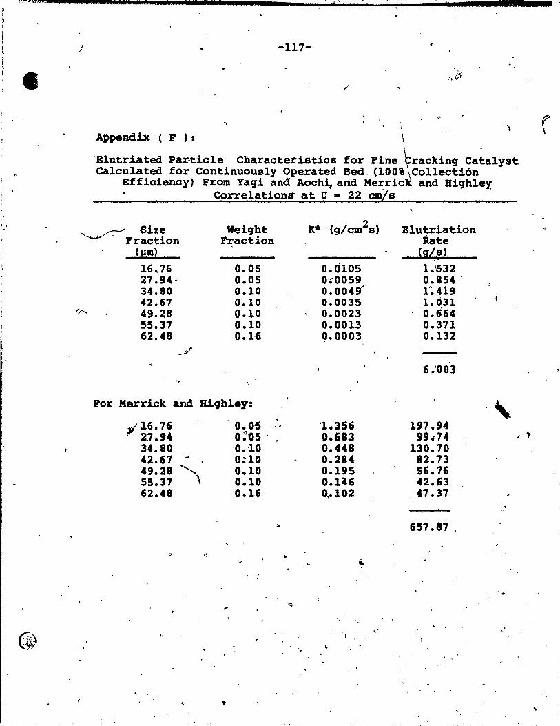
. '
1.
W~, •• JQ"A~J.$I.J*±.I.i""""""".b"" ..... t ..... ------~-~'~' __ ~~~~----'.I ... ll~I.*.t.a& ....... -~
/ -117-• 1
, l Appendix ( F ): \ .
'Elutriated Partiele' Characteristics for Pine ~rackin9 ca~alyst Calculated for Continuously Operated Bed, (100' Collection
Efficiency) From Yagi and AQch~and Me~ric and Bighley Correlations at U • 22 cm/s
~ Size - Fraction
Weiqht 'praction
Blutriation Rat.e
( }Jl1)
16.76 27.94-34.80 42.67
,~ 49.28 55.37 62.48
0.05 0.05 0.10 0.10 0.10 0.10 0.1-6
For Herrick and Biqbley:
i 16.76 21.94 34.80 42.67 -49.28 ~ 55.37 , 62.48
0
" "
<:
~
~
.. 0.05 ,0
0':'05 . 0.10 0:10 0.10 0.10 0.16
• (.
<:l
0.(Ü05 0.'0059 0.0049/ 0.0035 0.0023 0.0013 0.0003
'1.356 0.683 0.448 0.284 0.195 0.1'6 0,.10"2
: ~,
.
"
,.
s)
1. 32 O. 54' r. 19 1.031 0.664 0.371 0.132
6.'00l
197.94 99J74
130.70 82.73 56.76, 42.63 47.37
657.87 ,
, ,
.'

• .. ,< .. .. *
., Irl .JI.I:iI! ""'"
-118-
Appendix (G'): Statistical Tests to Establish Effect of Suction Pressure on Weight of Collected Particles 9 • fS
,
Statistical tests (37) were performed to establish
if the mean weight of sand collected per suh-population
differs ~r~m one euh-POPulation to another, as a function
of suctiop pressure, and if each sub-population mean differs " ~
/ 'from the overall mean (4.702 9). Alternative conclusions
are: c~:' Xl - x2 ' C2 : Xl ~ X2 The construction of the appropriate descision rule proceeds
as follows:
n l + n 2 - 2
where s2 ia the eatimate of the common variance. This 1 -
est!mate ia a weighted average(of the sample ~arianc.à s~ 2 and s2 ~
This .gives
The appropriate deei.ion rule i. two-.ided:
If
D > A2 conclude C2 D - X2 ,- Xl where Xl and x2 are the·two sample
" means based on sampie. nI and n2 respectively.
\"'
, -
"
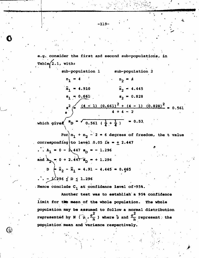
..
I~
..
-119-
e.g., conaider the first and second sub~popu1atioris, in
; ~a~l~r. ,1, wi th:
$ub-popu1ation
nl - 4
. - 4.910 xl -al .~ 0.661'
a2 (4 ..; 1)
• ,which qive -., 0.561
'\
1 '.
aub-popu!l.ation 2
nz - ~
-x2 - 4.445
a2 - 0.828
~0.661~2 + i
(4 - 1) <0.828)2 _
4 + 4 - 2
l l ( 4 ,+ l' ) -0.53,
t
0.561
+ n2 -'2 • 6 degreea of freedom, the t value
correapondi'ng 1ev~~ _0.05 ïa - ± 2.447 .. •• Al - 0 - SD - - 1.296
o - + 1.296
- -x 2 - Xl - 4.91 - 4.445 - O.~65 ,,'
.• ~9~ f' ,D ~ 1.296 .
. Bence conc1ude Cl at confidence leve1 of·9S'.
Another test was to eatabliah'a 95' confidence ~
limit for ~ me~n of the who1. population. The whole . " ("
,population may be assumed to follow a normal distribution . ~ 2, ,
representéd by N ~' an) where la and an repreaent;· the
pop~lation'mean and variance respeçtively.
". , , 1 .'
..
. ,
, "

• 1 "61 j 4_
, .
)
- -,
From Table (2.1) we hâve:
-120-
'=t. ' • __ 1/" ,.' ,
..
s - (a2/n) 1/2 _ 0.457 for the whole population
-
...
•
51.' fld 1.... :,~ !
~ i
:.
For normal distribution, 95% confidence interval corresponds
? to 1. 9fj, .hence:
- -x - 1.96 .0 < ~ ~ x + 1.9~ sD
or 4.102 1~96 x 0.457 < p < 4.702 + 1.96 x 0.457
3.806 < ~ < 5.598
Table (2.1) shows tbat a11 values of x satisfy .
the Above condition, i.e. with a confidence int:erva1 of./1 -" 95' we can con~lude that suction pressure has no effect
" on weight of' collected~pa~ticles •
. ..
"
: -
. (.
"
o •
. ..
•
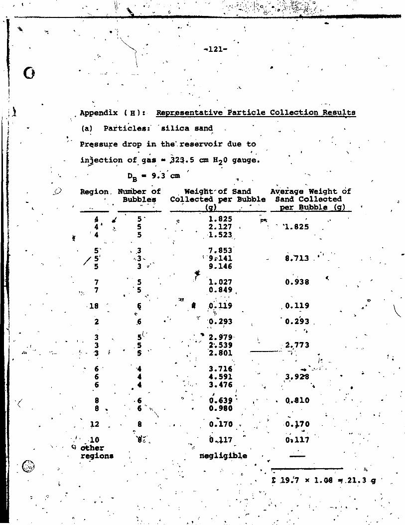
__ , III
)
\\: . : '\ î d .;a l , Mil
, 1 •
.' .. '" . .' ,
.. 121-
o ,1 ,
;} , Appendix (B):· Reprpsentative Partiele Collection Results •
1 \ (a) Partieles:" ailiea sand
" • " Pr~ssufé drop in the', reservoir due to
. ~
in)ecti~n of.qas. ~2~.S cm H20 gauge. , r
DB -9.3 cm .... '. , " . ~ ~
..(.> Region, Nuniber of Weight" of Sand Av;eraqe Weight of Bub~l~" Collected pe:r Bubble Sand Collected ,1 , . é
li} . \ Bubble !sO t. p!r
.. , 5 . ~ 1.825 PI' " 4-- 5 2.127
, '1. 825 • <"
~ '4 5 '1.523 , ,
5" .3 7.853 /5' .. ,3 ... l '9i.141 8.i1.3 . '
3 . " 9.146 'S '"
7 5 ,f-
1.027 0.938 6,
~
l-.,7-, 7 '5 0.849 . ",'
\ ' , ,
:;rJ .' 'iiI
·18 ,
~ • IO .• ~19 .0.119 •
'" JO!
l't- ' '" ~~ lt
2 .6 '1' '0.293 '0.293 ..
st- .. ~.,
l " . 1 3 ,~
~ ~ .. l' 2.979" : ,
3 ,5 2'.539 '. ·2.773 . , . "-." ( ., ~ 5 2.801
' , ,\Jo .- -t', ., . ,
Jo: ' . 6' -4 3.716 " --~.
6 4 4.591 ,
3.928 .. •
6 4 " , 3.476 \ ' . . 'J , .. \ • •
9 . .. ,( 8 ,6 >:! 0.63' • 0, •. 810 . ,
8 '" 6 "l->, 0.980
", , •• \ ... ;, 1
~2 8 0.1"0 ,0.}.70 . , .. ;-
"
~ .. .. '0 .
, 1 . ·10 ,,~ ....
0.,.1.17 0\117 c, "'-... . q Other ."
ci 0
re.glona 1t891i9~blr,e --Qt II'
~ ~";~ , ' . • =, .l\)
\" ~ 0 .
t ,19.'7 le 1.0.8 .,.21.39 i
~ ,1 , - ; " ' ,
~ -) ; . " .
~ . J , , \ _ .. .,. l '"
/> , . , . , , .

.. ",. . . ... " ~, -.;;
, .... , - , , : ' . ~, , :'-- .. , ,
r ~~~T, ': '~ç'-,~ J;
• '1 .' ..... .:-" ,> 1 ~,
~~ ~-
/11 IIU 3 MI ...... ,. L • .. (
r; F'
':l . -122 ...
., '>-
0 ' t,
,t .. t~~"-~Q
,~ tb) Particles:. silica sand ,
-\ . ,.
Press~r~ dro~ in the r~.ervoir. due~o . . ~ in;; ec~i.... of -buI>bl.e -"'-_ 411..LC!II._ ~~-:-~~ ____ .
- _ .~ - _ _u ~ "'-_'"' __
DB - 10.5 cm r-". Region Humber of~ Welght Of Sand Averaqe Weiqht of
t Bubbles Co11ected per Bubble Sand Collected 'ft 1
li~ ;2!r Bubble !9J t , ·4 2 ·6.649 4 3 ·~.560 " 7.443 4 3' 8 .. 308
(,
4 . 3 7.256
5 2 9.382 5 2 10.237 aO.285 5 2 11.139 5 2 10.3ê4,
, of 7 4 .' 4.121 3.814
J 7 .4 3.506
18 6 0.152 0.152
,~ " 0.283 0'.252' "
2 4 0.222 ., A .. -.
3' 3 6.468 -,
3 3 1.113 "'6-:t34 " , 3 3 6.186 3 3 5.1~8
, .' 'V 6 ~
, ~~ 10 .. 379 10.278, " - 10.171
'- c' , '. ~ -8, .e; 0.931.. . 1.111 " 8: 6 1.2'97 '\ " .
1> 12! 6 O.65~ 0.653 , .. 10J 8
i 0.,1.82 ~ 0:1'2 ...,
\ ';
~ othe ~~.~
reqi ns ~
negl+~ible '" --- , -1' . ... , ....
h . \, .~
40;4 ' '- 1: ;c 1. 08. ~ "43.' g ~~ ~
'" , . .. /" -. ,
~ ~
..r, "
II1II

o
• • .
-< ....
,
({fi
( ," - ~ ,
4 • • 1 1
-123-. ,
(c) particles: FCC
Pressuré drop in the reservo!r'due to
inj'ection of bubble - 49.3 cm Bzo gauge
DB - 5.0 CID
Region Number of "Weiqht of FCC Bubbles Collected ~r Bubble
, (9) .1.
4 8 0.439 4 8 ~
0.363
5 8 0.028 5 8 0.033
7 8 negligible .. 18 8 0.04' 18 8 -0.065
2 10 0~19', 2- 10 0.295
3 7 ' 2.123 3 7 (, 3.174
1
3 7 3.057 '.'
r.'
6 8 ,
0.450 , t
6 " ,
8 0.'96 ' 6 8 0.796
other ,'l
ragions negliglb1e. '" ;: ..
~
..
• 3
... Average Weight of
Fee Co11ected . per~Bubble
(g)-
0,.313
* . 0.030
J
0.057
0.24'
) . 0.581
, <
...' , '. '
, .. ' + t 4 .. () )( 1.08 ,- 4.3 9'
•
"
".!Ii.
" , " ~,' , ~,~ .. '
'. ~ 1 _ • "" '"
"
, .
.~.j. ~
" . " '
'.
. , . -
,,' :,' , .. L~ __________ " _J ••• lIlllUS!ll!lz.1.y .U_;S:_;"'ti.;; .;I_1i _._
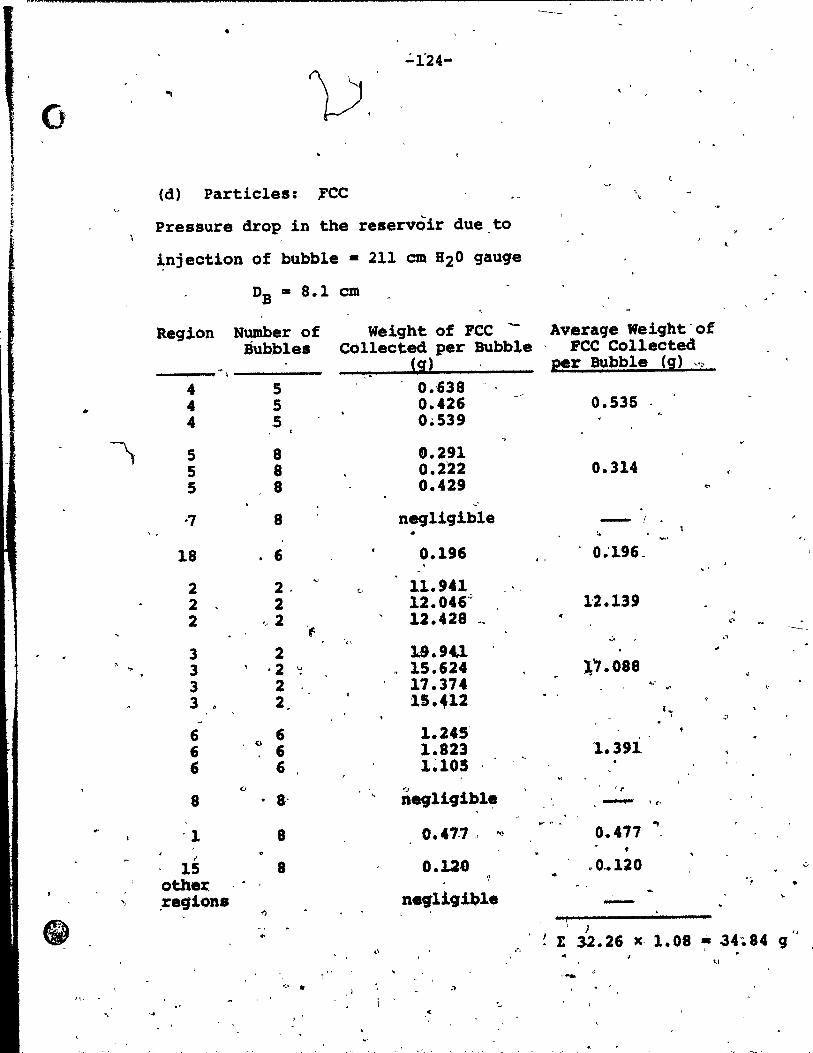
,~---,_.--------------------------------------------------'-, •
":'i24-
o Î-> (d) Partic1es: ,Fce " ,
Pressure drop in the reservoir due to ~
~njection of bubb1e • 211 cm 820 gauge
DB • 8.1 cm
Region Number of Weight of PCC Average Weight'of Bubbles e~llected per Bubb1e FCC Collected
ii! 2!r Bubble (g) f",J.;r
4 5 0.'638 .. 4 5 0.426 0.535
4 5 0.539 ,
" 5 8 0.291 5 8 0.2'22 0.314 (,
5 8 0.429 ~,
-7 8 negligible - 1 , . 4
'.
18 6 0.196 0;196. .'
2 2. v 11.941 2 2 12.046'" 1'2.139 2 <,2 12.428 _ •
'f C" . -
'" ..::. ., 3 2 1-9.9U ,
3 , -2 u 15.624 :\".088 .
3 2 11.374 .. ' 3 2 15.412
(~ 1 ,;,
6 6 1.245' (;
(l
6 1.823 1.391 6 6 1~105 "
<1 (J , ~
8 8· n891i9ibl~ - 'r . '
V" .. "1>
'1 8 0.47.' " '" 0.477 ,I
15 8 0.120 .0 .• 120 ,:,
oth.x f •
" ,regiofts neg-ligible -'l")
ft " \ } ..
," ,', E 32.26 x· 1.08 ~ 34~84 9 .. ~l
"-. J", ...
,1 :> ... '-
" ."-

1 f i
• ... A.? mu
0,
•
. •
.. .. ~ .
.... ,- 't .',
-125-
(e) Partiqles: ballotini
Pressure drop in the reservoir due to
injection of bubble • 133.6 cm B20 gauqe
." .. ~ "
•
DB • 6 •. 9 cm 1 -r 1 ;l' (7
• ~eqion Number of
Bubbles
4 ~ 6 4 6 4 _.6
5 8 '.'
7 8
18 8
2 6 2 6
"
3 , 6 3 6 3 . 6
6 6 '6 ~ ·6 6 6
1 6
" 14 8 ~
other .. reqiona
'\ , Weiqht of Ballotini Collected per Bubble
,~
·(i~
0.206 0.243 0.176
n.gliqib1e
neqliqJ.blè
0.080
1.579 1.349
2.215 '2.239- f}
2.374
0.235 ", 0.222 0~451
0.163 , \
0.087
.nagligible
.. , . l" ~ ~ ....
< 7
, .
Average Weiqht of B41lotini Collected
per Bubble (9) •
. .. .
0.208
0.303
0.163
0.087
-
;. "
\ 1
.:
u. luE "
'.
."

'. i !
,-< 1J _"~
: {lf~i.;=;:~~ , . ,~::, . ,; Et
,
... o '(
/
" (f) Partic1es: \ ba110tini "
Pressure drop in 'the reservoir due to .
injection of bubble'· 386.8 ~ 820 gauge
'0 - 9.8 'cm B
Region Number,of~of~Bal1otini Average weigbt of
" "Buh les Col ted per Bubble Ballotini Co11ected
~ - .:.~ li! . E!r Bubble ~i) '-'l,
,4 6.998 7.212 4 7.426 ri 1
5 7.564 8.431' 5 9.291 .' ~
7 l 1.652 '1.652
18 / 0.300 0.300
, ~ ,
2 / 7 0.904 0.815 2 / 7 0.681
/ ' , " c.
3 / 3 14.701 ,14 .. 888 3 -. 3 15.075 ,. ' " ....
6 3 16.510 6, 3 12.091 14.39,9 .:.
t 3 17.048 3 .. ~15.249 ~
'8 5 \ 1.290 6·457 ~,
8 5 . 5.623 '" other fi"'" <: ... ' ..
'ragions na9'1i9'ib~e -~ 54.15 ~ 1.08 • 58.49 9
o
'. : ..... ' .. ,
~ . . .'
" • f,'

-127--
o "
"""'\ .
.- 1 o
.. . -'.
\ Appendix ( 1 ) : j . \~)
... ~
Partiele ~rajactory M04el Computer pr09rAJpme " t «+
~
" , ~I'l
, ft
l'
+ .. >
"" ~ '., " ,
'1
,
4." " .
)
,',
.. . . " • ~
,~
D '.'
. ,
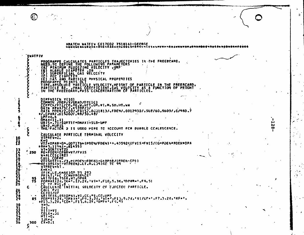
_ li: .u • .. gAl WWQ;asÙ' ,,.,044 )0 .. '"' •• _'''_'"~_ ::;;;> 1«:::::' '!II_
. @ ~~. . " ( 0 \
/ v
~ftATCH W1TFI~ CE17C02 7518161-GECRr.e " '1 •• * •• 6a ••• ~_ •• ~.~4~.~ ••••••••••• ~~~t1.~.~.~~ •••••• *~*4*** .... ~ ••• * •••• $ ••••• * •• c ~ ii • ~
- -twATFIV
-'1 4 5
9 , -Ii
fi 19",
1 PBfJÇA'''JfE CAlCtJUTES PU'ICLfS TlUJECTCRlES lf\: J, .. e FREEl!è'RO. " .uP~ TC OEfl .. e THE FOllUW tfG PAftAf4ftERS ' " ' 1"" "root" M FlUOlllt4G VElOCITV '.!IMF ' .
1 ' 81 III l (tIAJfetfA .08 r C SUPE Itl'~ GAS VELCCITY C pee c U.·CT-f~
i CE. r.A~ AND PARTIClE PHYSICAl PPOPE~TJES ' PROr.PA~~E p~ NTS ClT " Tl"E 1'P.SOlull PARTICtE VE
EOCITY 1HFtr.HT OF PARTIClE rH THe FREERCARO t
P RT elE RE. J~RAC CCerfl JeNTl~.s VElCCtTY AS A FUNC'I~ OF ~eIGHT _ nt THE FREEfOARO,Jf'SS co. ENTA TlON CF P.U ICLES. . , -
C ,1 C ,.-'"
DfJffNSICtl VnO) ,
<~
CONNON loeP/Y/GRAD/OY(l~' ~ CC~~C~/FT~/COtREtWIHTT.UP',YI.H.SU,HT.~W DAT~ 'JfAX/IC/!IC~ Op/)/ ' , DATA PDE~I .t I,F~IS/.O~J1813~,FDeN/.0012q30/.SUP/60.9600I,G/qBO.7
.1',.CPIIl/.Ol ~o 1,R8/3\J.481 <,
a:"F -'l.t, . OMIX-I1.11 1 ••
U81S-.71~SQ'Tlr.-oM'.'+Sl8-~F ' ' UB-2.·U!lS .
, THE,JFAC1CR 2 1 S useo .,eAE TC -,ceco.n FeR fUeBLE CC_LF.SCENCE.
~~~~~~~!! 'UTtCL,E T~"'I~Al V~LCC ITY ;".
~j1.0PAR~G •• ~0717~fPne~/FnE~" •• 4~592~'FYfS~FYI~/rG"PDe~.poé~.OPA +A".'.) 1"~(-.'1415' ,-vt.SQRTt~TZ" -
# 250 AE-FDE'C 4 CPlhVT If'Y JS ' W-llC~lC(RE' , CAU CDFRE - . V'hSCltT(" .11.ait' Pf)[lII-fDf:N ).t(à.OP.\R Il FOU .. '·C". J
.--....FURS''tT-YTPRE'N.LT.41.cl~Jr.r. TC qllj " YTPRE~-,*T ~ ,
20, . KaK+l -. , IFtK.LE.K~l~)r.o Tn 2~) , .
ii l, 5~ I~ 30
Il !II 35 36
PRJ~Tf'~( ~(NVFRr.E~CEt ' 9S ~qITF 61 7S'KtYT rOP_R ' lS FOR"ArJl(t~K.'t ?,2X,·V,-·,Fln.5,3X.·OP~.t,Fq.~J
t"C 7 7 \ ,. -1 ,li • ' C CAlCll'AJe-INlTlAl ~ElnCHY CF "fJfCTEC rARTIClE.
CAll PH CC·vl/cr
.• hRtTF.tbl0S'D~.X,YJJCC.~E,Cr..U~F 85 FOR"'l\1f i" 1 t (1~6 )(.' II' q. 3.21: • ' "1 - ... F 11. '5 , ? IC. • V 1/l;"'" • F 1.) • 2lC , • RF .. • ,
+Fl'l.3,2)f, CO.',Fl .. 6,2lC, ·Ulo'fa',f4J.C;' _ '.'1. t-l y CI t *V 1. r.eLX-.ll Hf( =0. IJKftlJ
100 eX-O.l C .... ,r- "
I
..
~'
,f
-- ~ }~ "
'\
"
~ ,
-;"
'. ....
"
N Q)
1
J
" ,'"
-:'
,\i
~ ": ., '" , :.fi._

~_ l!!! J.. il Ji .), ,. 1- 1 _ JE E Ut "... ... .. no c.» ati < QII n,,*, ).,..",......-.--.~ --------.---~,
~ '-
'"
Q
'"
JI . ç 39 -C
-4-0 " ~
:1· ~,
@
,.,. 4S
c"V C
- 46 41 4a 49
-50
li 51·-c,
100 120
ICO tlS
it 59 . \i, 60 ---n- .
12
61 C 15 -. il t' 1° .,1 73 111
~.
c
1 -
....
l utc'ltr JIC+ 1 .. " ... tl CALCUL Tf ~fXT STEP HflGtfT RfAChEO'ev A p~RTrCtE. MTaHTI+YC1,iOELX tfTl·Hl .
~
)-
"
il
CAtGUtlTE FLUX FII,JI OF EJECTEO PARTIClE CF SIle OPI A~C l~ITIAl VElC:CITV YJ. .. TFlhO.28B -P .. F ... TF}t,··WII FlUl(OaÜ.281l Ft~XI-FLUXO'lIPVF 0
r -CAlCl!\UE ..... SS cottceNTRA" C~ CF PAf.TlCle CF. SilE OPI AlfO lUTlAl
f~lOC TY I/J t\C~.flUIIJARSCYf ft" fHTI.lT.O.O)t;O TC! 11,) -
CAlt 'ERS~C'.OElX,OX.~COS~~C05,1,'1~Ot(20a, . ,.IFCMr.ClIJIlJ!i}.NF..O,GO .,.C 1 g' • "A' TEe t t 12u) Je t Yfl' JtfT ,RE fe Isu, CUNCN FOPMATC~.JtT,Mf.. ,,1.~,4Xt· 8S.P.MClE YE~ •• ·tF4!4.4X1·~r.T.·JFR.4t
+4X,' RE .PAR.Il •• F9.,., 4)(, Cc-·. FI). 4,1. t • su- .. F1.lt t;')(, .CI.'NC ..... ,t' 8.6' "
GO 10 l~J -kRITEC 1130lX.,VClt FOR"AlflX.·J~ F.r,RATI~~ FAllS AT X-'tFIO.~,lx,·Y-·,Flù.51 CElX-CElX . IF(X.GEIP.)~O ro 110 GO to l~~ . . ~RITF.C611BUtX ytl' . FOq~At'lX •• ~.ttFl~.7.ZX,·v."Fl~.7t corH-ltfUE . - -.STCP EMO--
. , -SU8POlrl~E ~FRS~(X~nf.l'JnX.OX~I~tTClK~t~.~.~, '~Tfr." AT es F KnH x Tu' (lC +llet.lC 1 . , nx ,~ FSTIM~Te FO~ thTF~qITIOH $TFP NfC~~SARY nXM1N I~ MfflllMUM ~, p, L.f~rH Tf. BE p-ER"'nTFO TCLK~ h REGUIREO .. CUUCy· -.. IS M'''IlER cr- r.Ff'HU"~'H VARIAl\lES co~r~Cl r_~~srF.~REC· le ~I~ST l~~el If I~Ter.RITlc~ FAllS:x
u .. elttf cru",,,, ~Iew VALt;:'; _, -CCli. TqCl TIU"SFFRRfl: TC SFCN~t I.HFl IF 1~ITciiU fION FAit $:
2YCII lHe, CCNTAlh ~CST PFCf~~ ~[~~~CT'VAlU~~ 1" FlTtiER C~SE; -0.< Cr.~HI"'~ CV'P-:'H srco- lË,\;CTH Ctf'fNSlft\ YU., .lVr.t.flIL\"FK(~.lt'I,'WflJ' ca""t)t\ IOFf'/Y tr.RAr.1I1Y TOl Aa~ê~ rOLK~~ TOlf'-r LAnf. Ft'TS.C~t~1 X+~.5 t~r!. .. 1f IA(F ofF'i' Ifll~T~.Lr.llt~lSal
. eX.OH X/IMS F'll T~lJ)('~ • CI) rf'! "
. t:APr.p ( .. Fete 1 IflrRR.~r.TClAI Gr ln ~J
IFlfNP.lT.TnI'H Gft~Tr. 21
','
, "
~ MERS N"lO 1 '~E~S"'llrf~ • MeQStfCn MERS""04 ~ERS~I)~'i Hr:QSNOC~
A~C YCI'~EP.S~CC7· "'F.P SO.:,,'OI\
'( \l'fO ... :~ Cj"40C ~ \1F')~~lCl :: M~RC;~\)~ 1 "'E~S~4.ill NFR'i..,Cl1 HP$N)l4 1IF.°S"·.15 II!ERC;',,11b -
• _ \·E·')S .... H 1
C 75
t~Trr.IL\rr'l·~ ~o\TlSf ACtn.~Y: r:AlrulHr: ~E'" PrJ ~!TS '3 r.r. l t·lt~· ' -y ~
""r:~ S \-H'} "'f.~ 9h.1.1-l \4F.J~"O;'~ "'~I''; \ l71 "E~S',,: ~2 ~tF.Q~"'Cl:t "E~C;"J~4 "1: P S I\,t". t.tE'-''S'"4ù?t,
..
~
l '\ ~
•
o
~
1 .... IV \D 1
'\, 1 . \_,
. 1
J'
i.
. , ~
~
;":
p
" ','
.. ~ ... ~--_.'" ." ... ~ 1

~
! J ai·,i l ' : . $ i . i • b ........ " 1 1 _t il. 5 .... '" ... a;u,.1!i""8!t:4A ........ '~ ... - ~,_ •• ~......,....,... .. _ ",* ,"CH ...
~
.. '! 2 ~ffl.yOLOtf.+O~~*F~flll)+2.0.FKI4.1)+o.~rf~r5,') 1 IF NTS,EOr1' ~ETURN ., 6 INT .,,, $- . - .
• C PRE~EIl'lE CUluaENT VJlUES 79 .~ XOln.x 80 CC 5 ,altH !1 5.VOlD' ;.YCI, 82. . ItlAlF.O ' 83· Ge TC 9 •
C ERRO~ !XCESSIYF.I H.lVE STEP '14 e~ 86
'el 88
&9
20 DX.O.~"'DX lFCOX.ll.OXMIH' GO TO 19 I ~TS.'''1S+fUS HAlF-l . GO TO 8 <
C STF.P le~CTH TCD S~j~LI IHTECIlATtOH FAlLS 19 X-XOlD '.
CO 23 1.1 .. 21 'f' IJsvelel.,
~
',-
RETURt. 2 C ERROR S~A~l: STEP \E"rJITH ~AY ~F INCREASEO kF PCSSIBLE C CHEC.K 1 F STEP Pllev ou 1." H4l ven • .pReYENTS C'tCU~f;)
21 JFfHfJtFeec,t' GO TO! "
lï 93
~t 96
91 98
. ,'If'
IIJl i~ 08 09 no
t CHf!CK 'IF J~ E~f" IDU8 E. I~TSI •
t IF"\CllPlE~2 .EC.lttTSI GO TO 21 VOT POSSI~LEJ IHTS EDO' CO TO 3
, CCIIF\lE -STEP LE .. eT" . 2Z INT~aJnUlLE J~ .
OX--2 .'01· - -t 8 ~~L~~~~xnel'ST PDUn, .kO '"lEUAJE 'UTH ~6" 01
, CO l fal ~ 7 V'f'.YCL6,1' r
. X-~OlC ' V" -'A'N' ltItEGRATIOH PRCC!S~ SURTS Hflte *~,.:: •. C 'nvA~re x BI ox
l • 9 UU tEJtJ\fS X,N) .' aD 18 1$-11'
• GO Ta (!1,30.1?.3l,30',IS .,1 XaX+FflUlT
GO TO ,~ 32 •• X.O.5~F"UlT
• GO TP 10 33 •• )lClCttx
C ~PhAlE ~'I' 1
... '
•
III lb . C
30'CO IJ 1*11." FK'I~"'·~~UlT4DV(I. GO tC .11.12tl'tl~.1~,.IS P~F"lt'C~ 4T X.~/l.'
11'' -1 5
116 , U1
118 t19
11 vel,-Veltel). Ktl, •• GC Tr. Je
C • eORIt Et lC~ FOR ()(+O X" • ( 12 YI' ).vnee J).~.5I,(n((t, thfkC?lU
GO 10 le " C ~ IDYA~Cf TO"XtOX/?'
13 y Cl ,.YClI.':ct, +0. 'nib Ffi, f 1, U+'. t ,?S',FIf( 3. ft GC Tt: 1 ~ • , ~tl'l"t4f.F rn ()Ctr..)
-C J
. '
')
.~
"ERSN027 ~eR-SN028-MER SN02~ fl,eRS,.031.l "EPS,.031 "ERSNCI'12 ~ERSNO'H .. eQCjN034 "EQS~û3" "'ER S~~Ol6 "'ERSN~31 ~eflSN018 lIER SN(f~l) ~EQS~04') MEqS"\O~l ~fRSN042 Ml:''''C4 " "'ERSNOIt4 .... eRs~841j MfP SN 4il ,.ERSN.Hl "'ERSNlItR MEPSN04<J "ER C\~\I5,1 Mep.SNl'H ~fItSN0I52 ~E~S~-I\l53 "'FRS~054 "'elt SI.vt;~ "'ER sr'fl56 "'ERSNH~7 "'f.I1SI\058 >.1ERSltOS9 "EIlSN06J ~ERSti..JbJ MERS"O~2 "'E~«iNOt3 "fRSIlrOb4 "'fR s"'\h)61 "'EJ.lS'-IOl:6 "E~S""(\b7 MEPSNl)b"
" .M(R Sl40'f: '; "!:RS~v7l,) "E~S':lll MEQ!\UC72 "fRSNù7l .,r~~014 *"EqS".,:l1j "'ERSN\l16 "'EASNù7r ~leRS1'4Clll f~ER~'''C'Jq ~::PS"'ORJ ~·.ERS"OPl MEl' S~~CP2 "fRSt..::)~' "ER $1\(11'4 "fIlSNlIR'i "f~S·~OP.6
....
o
.. 1 .... W o 1
'.
,
-------------_.~~~ --------... ~ ..... ~ .... ~.,...->-~ .... '!>~ '-~- ........ ~
'1;
jt
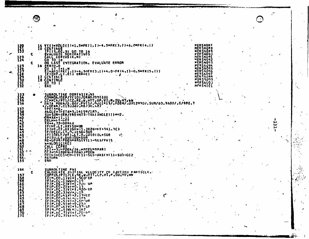
8 '1 :, 't if :1 1 d ,_ cl lU' "ilS".": l ... ; ""' .... '...-..-_h __________ _
Ci
~
® ,
,., co "
iF nt 113 124
1Il.. ·,11 31 32
-Uf ,
r . 38 19 40
U lU U! ~~
ra 49 sa
c
c
li
lU Cf ,.
lU, .
155
15~
}57 c
i e 161 lt
li U4 u, lU 14' lU 69 po ",11
'"
.$v
'" /1
13 ylLJiX8~C(II.l.5.FK(1.')-•• 5.F~(],r.+6.C*FK(4,'t , i~1I S.EC. Sj GO TO 16 .
AlL CEPIV (X,N' '. _~VALUArE 0 RIVATIVES
o TO 13 . ON lAST I~TEGRA1IQ~t eVALUATE F.R~OR
16 fAR-O.O , ca rI f-l," . . E J -Af\S FIC 1.1 '-It. SAFI( 13 .. 1 Hit. O·'FI< f4, l' -o .• '-fi( C~. III tFtEftP.U .en ERR-el _ 1 .
i l CC~TI~(f " 8 CONTlNI..e- . '
- GO TD 1 • Ellie
. -
~
·SUBRO\. Tl"E PERI"SI.;~" . " . '. -COI1MO .. ,OEP/YtlO' IGR"O/OYUQ. ~ • • CC""Cf\/PTlIr..t1:RE W fHTT, U-PtVlifil, SUI M'if kN " •
• DA TA POEfIC/2. 0'11 .Jv S/."ùO "n/.FDf:IfI'.Ot}12Q,:\O/ f SUP,/6:).96001 .G/9'O." ."np&R/.C15:l1l~/.RB/]O.It~1 .'
~
Tt'ElA-O. l . A~GLE.TfoeU-l~ 141'lq1lM.. • SU.StJR~(R"IfRl).Hn·IU~f .\f«;lE)' '."2. ~R.AX·ll.l] . C~L"·~T-~TT ' -r )('"-4 72"'06"I.X fFtHT.U.XX'".SU-Uf\ "
1 F-U·' .CT.U ISU·-l. }8l6u t-T+34,l. 1Cl FfDeLH.LT.ft.a'Su.~ue
clf(CnEl~/~'l;Lr.O.'~lO)SL.sue ~ IFfSU.LE sue SU-SUR Re-UP~R~FOEh*A~S1Yll1~~~I/FYIS "·'lOGlCCR\:, , CAll CCFRE ~ . CC t ... , ~:\lFDEf\/.4 ... PflF. ... *IlPAR' CC1.-r.·CPOfN-fnEH"PCEk '. ('IY (tH.CC1~O"" ye 1)-StJ)~.zA8S( V, U-SUJ-CCl ReTUR~ . END ~
•
~ "
SU8ROl TINE PVI - , • CA~CUL'Te JkrT'~l V(lOCITY CF F.JrCTFU P4RTICL~.· CO,.,fttJ~/P Tl 1< c I~ElW _IH Tt t. t-. v 1 .ft .sut'ir,,,," t f pt. 10 • l} v,- • Ii on1p . . , 11f~. ,.t WW.O.l~ JFf~. '.2 vr.l.l~o u~ .' IF '.J4.E~. 2l"~.O.11 , Ft" .Fè.l IV ,- t. t;2(l .. UP Ft~.Eè.l)~~.j.l~_ Ffft.EC.4t.ifl-?-J 14 t;1! lFI~.fO.4J~~-~.)P5 IF(H.FC.S'vJz2.4P~Ufl IFf~.~C.5'w~.O.Z3~ ·IFCM.fr.t)Vl-l.5~~~ 'fCM.Ft.!IW.·~.l~l
, tf("'.~C.1JVI.l.7tr'(ln. IF,"' • .fO.l,"ts:o.ln"
.,;
", '-
, .
•
(-
~ERSN01t1 MERSNQP.8 MERSNOn P'ER$N09;) HERSN091 ~ERSNQ-;2 ~eItSlljo(n "E~S~ù94 MERSNOC;5 ",eASN()q6 fofEftSfil097 MER~Nll9'l • "E~S'l\)q'1 . "'';PSNIOJ f4FMS~lCl
'.
: \.~
,"
~
o
...
"
D
. '
....
1 ..... W' .... 1
#
"
.'
.' ,
'", /::,:':,:":. ~~::':~t~
,: ~:;l, ~::'ft , .
" ..
, '
. \ M zn 6a 1 e 'r11l!, i

.
"
1
"
~ . <-
~
~ ...
..
~l ~ ...
. ~ ~~
-,
,<
" -
œ ..
lU 176
'" r ."
"0 b III
,j
Ü· Il 9-
... ~ ~
<0:
.,
, , ' ..
C
,. ..
('
_f'
IF'~.EQ."VJ.ll.SO~~~ 't~.E(.8)W~.O.~01 E ,~,,~ -
rttfl
.,.
...
4lr.ULA1E OJA~ ~O(FFtClf" fRC- A PlfC~-~ISe FIT TC T~E CC-., CUAVF. n~~/Pfl/,O\P_.W.HtT.L •• Vll-'!~'""~. ll.'~Tr~E CCFAI' • ~ ,
F lU:. •• C,bl. 16 • ... /RI.! FI~f.Ai •. 1·'~DI_'~LF.~),JCC.2",,'.f •• l •• ~ttllS •• fA.fo~1-.Q'.W" f .F.G " O. "/l.ft .L".1t C".~"./Af"llo.tlll' .' ....... 61'15'
It(:"r. • .... ,"~ .. r.It1: to ~ cn-IO ... ( 1.1:.'''- 1!" "w •• 1SStl··~" •• d.htl.,ltlor ...... 4~ .ll. i .f 1 •• 'u-lo •••• ,. 2." Il., J ............ ,t ••
"Ije .rT .l"ll" .AtJf' .PoF:l li .... 41"" ":1'·1 (1." • C -1. 'U ;lI- .,. .7· le-. 00 'lit ..... ~.
F '!.GT ••• 4E4.A'~.~f. t.l.'Re~'~O·1r,.,p(-".111.1.~~O~c~-,,1'4t' .. • +!4'. -ioc,.l. }.e~.A"'1sllF.tLf.4.F"r.n.7tt,,'ft-"l. '\"w - '
Fe_ .la.4 .~s,~'C."t .ll! t'iE6 ,ee- .1'·v-.It'1 F" .Gl.1 ... 6,CD •• l~-ft.~ a(
1,--" ' Q'
1 c:
"
...
. , k·'· ...
\ ,-
,. '"', ". 'Iô. -
~
~
}
!
" Q
-, ' t:'
.. -'Il..
-.' ~ .. J
'i.
41
~ / ~ ,
~
i s , ,r !:; ,.'
%
\
,.
o
'Ii
:)
r
-.
,.,
.~
;: 1 <: '
.? ~
'-
1 1-' w ~ 1
..
Cl
1 •
tU , d f
),' " l'_'~".._~~
-c
• ,
-\ c
'1.
2.
/ /
REFERENCES
Miyauchi, T. and, Furusaki, S., AtI. Chem. Enq. J., ~, 1087 (1974). . -" Avede~ian, M.M., \Paper Presentea., at Canadian Ch!!lllica1 Engng •. Conference, Ottawa, 1974. _
3. Zanz, F.A. and Weil, N.A., A. 1. Chem. Eni. 9., !, 472 (1958). '
4. Soroko, V.E., Mikha1ev, M.r •. and 'Mukh1enov, l.P., Intern. Chem., Eng., 2., . 280, (1969),:,
5. 'Fourno~, A.B.; Bergougnou, M.~. and Baker, C~G., Canad. J. Chem. :E:ni" -g,. 401 (1~73).
t:I 1
6. Cheremisinoff, P. and ~o, B., .process Tech. Intern., !l, 12·1 (1973) '. 1
7. Do, B.T., Grace~ J.R. and Clift, R., PoWder Tech. !, 1.95 (1972),.
9.
1:# ,~",.'
Mérrick, D. and Highley, J., A.I'. Chem. En~~ SxmP. Series, 70, no. 137, 366 (1972). -Lewis, W'.K., Gi1ii1and, E.R. and Lang, P.M., Chem. Eng.
,prog. Sympa Seriea, !!' no. 38, 65 C~962).
10. Yagi,.S. and Aochi, T., paper Pre.ented &t the Society of' Chem. Eng. (Japan)', Spring term, -1955.
11. Wen, C.Y. and Hashinger, R.P., A:I'. Chem. Enq. J.; .~ !, ~20 t!960). .
12. "nevâ, M. and Wen, C.Y.~ ~. Davidson and-Harrison, '-F1uiaization", ·Ch. 14, Adademie Press, 'London and New York (1971). , ".
- 1 • 13. Large, J.E., Martinie, 'Y. 1 and Bergougnou, M.A., J?aper
Presented at the Intern. Powder and Bulk Solide Handlinq ~nd_proce.Bin9 confer~ncer May 1976. . ' ••
, . ' '
----------------------------..... ~
J .4._
o i 1
(1'
...
....
~
~ .
dl. , 1 -
- ", l
-134.:-
Taft, R., Water Research Centre, Report no. TWRC-10, 1969. .. \,
15. ~ Z,nz, F.A. and smith, ~, Hydrocarbon Processinq, 2, 1~3 (1973)~ ~, 1 .-
16. B1yàkher, x. and Pavlov, F."Xntern. Chem.Eng. , !, 47 (1966).
'. . . 1 ~ ,
11. Yagi, 'S. and Kunii, O., Chem. Mach: Ja2an, !i, 288, . 1:;: (1952) •
Yagi, -s. Kuhii, c
18. and O.; Chem. En9:~ Ja2an, 19, ~OO (1955) ~ e ..
"" -. .. 19. Osberg, G.L. and Char~esworth, 0.8.# CheIn. En9:. Proqr.,
47, 566 (1951)., , - . ,) ..
20. Leva, M., Chem. Eng. Progr., !l, 39 (1951); .~
21. Hyman, o." M.S. Thesis, M.I~T. Cambridge (19-52). ,
22. Mori, S. and Wen, C.Y.i A.X. Chem. En9:- 'J.,.ll,' 109 (1975). i -, - .
-' . 23. Werther, J~, Fl~idizatiori.Tech_, ed. D;L. Keairns, l,
, 215" (1976) •
< "24.Î _6, P.H .. and' Bverel;t, D.J., Trans. In.t. eb ..... En!!., Ë,Q., 55 (1972)'. ~
• l' , 25. Geldart, O., Powde~ Tech. ,f,' 163 (1972).
, f
•
'.
26. Kaéo'wK. and Wen, C.Y., Cbam. Eng. Sei., 24, 1351 (1969). . . ~
27.
"
•• 4
/
Park, W.H. ~ K~q,~ W.,rK., caPe., C.B. and Osberg, "G.n.; '.--1 Ch'eDl. Eng_ Sei., ~, 8~.1 (1969), . Q'" -.",..... .~ ___ • ___ • ,_
... - '" ~
28. Whiteheadt' A.B. and Young, A.O., Proc. Int.ern .. Sympa on -l'luidization, Eindhov,n, ~84 (196:t~). .. . . .
t:.\y ,
29. '-Ifasui, G. 'and JOhanson, L.N., ,
Am.plnst. Cham. Ingra, J., !, 445 (1958). .~; . ..,
, 1
1
i 1 1
C
Davidson, J~F. and Barri~ont D., ·Fluidiz~ion »artieles·, ~ \ .Cambridge University Press., 1963. -', . 'f> .• "
30.
1.
",
"'"' ~
f .. . h , , '..
,"'" -
o
. ,
, .
. .
,
;'
, . (', .. u ..
3i. Rowe, \ P.;., ~ien~~, ~~n~~'Aqbim, A.J., Trans. Inst., Cham. Enqrs.,~~·3i'o (1972).
-o ,
32. Rowe, P.N. and aenwood, G.A., Trans. In.t. Chem. Engrs., !!, 41 (196).).
33.
34.
35 •
36.
3n
Kehoe, P.W., Ph.D. Thesis, 'Cambridge, 1969.
Garner"F., Ellis, S., and Lacey, J.,'Trans. Inst. Chem. Envrs ., 11,222 (1954).
NeW!t~,. D~M., Dombrowski, ~ N. ;nB ~el.màn, F.R.'; Trans. Inst. Chem. Engrs., l!, 244 (1954). -'
Malln~yref F., J. Geo~hYs. Res.,~l1, ~52i1 (1972). _ ,
Whitmore, ~., Neter, J. and Wasserman, W., "Self Correctin9 Problems' in Statistics~, Allyn and Bacon, Inc.,
i Boston (1971). Il ' -
Rowe, P.N •. and Partri,dge, B.A., Trans. -In.t. Chen. En9., li, '1'157, (1965) •
39. Ha;rison, D. and Leunq,",'·L.S., Trans. Inst. Chem. Eng., . 40, 146 (1962). : • - ..
40. Grace, J .R." Tbe Canad.~ .J;:1 Chelll. Eng., !!" 30 (1970) ,. t
*' 41. Clift, R., Grace, a .R. and Weber, M.', " Bubbles , Drops and Particles", Academie P~ess, 1977. ù
1 •
42. Chiba, 'l'.,' Térashima, ·i. and KObayashi, R., JA Cham. Eng., Ja~n, !' 78. :(1973). . . ~.-
, 43. Clift, R •. and Grace, ~.R., Trans. In.t. Cham. Enqrs., 5&,
, 0 ,364 (1972)., " -• ____ l' , ..
u
4~ •.. Miwa, K., Mori, S.,' J(ato, T. anc1' Muchi, I., Chem. En9., Tokyo, !!, 770 (1971).
45.
46.
Cooke, >M.J., Barris, W., 'Bighley, J. and. Williams, ln.t. Cham. Boirs. Symp. Séries, ~ (1968).
- J _ "'.
Nicklin, D.J", Ch_. Eng. '·'Soi., !l~ 693 (1962).
( •
D.~.,
J
. "
,
\.
" ,
" .... Ir 1 w~
----------------~~------------~----~--~~~----~------....... "~
·1 (> i
"
:"136-
ô
t~r~er, J., CheIll. Eng. Sei., 21, '971 (1966). 1 ~. ~race, J.R. and Barrison, O •. , Chem. Enq. Sci., ll., rn (1969). •
47.
, 48.
!Py1e, D.L. and Harrison, D., Chem. -Enq. Sci., ll, 5,31 '(1967). "" (, CP
49.
50. j'Grace, J.R. and C1ift, R., Cham.' Eni' Sci. 1 29,' 327 (1974) •
51. Abramovich, G.N., "'!'he Theory of Turbulent Jets", The M.I.T. Press, Cambridqe, 1963.
;...,. , 52. 'Matsflln; J.M., A. Ie'ChemEnq •. SYDl,P. Series, ll, I\C? 128·,
301 (Î.97~).. , ' , .
,53. ,1 Stemerd1ng, S., Cham: Ing. Sei., li, 599. (1962). 1 ~
54. Zènz, F.A. and Othmer" P~F." "Fluidization and F1uid Partie1e Systems", Reinhold, New York (1960).
55. "
L4Unq, L.S., Wilesi R.J. and ~ick1in, D.J., Ind. ERq. Chesne Procas. ])es.' Deve1op.,. ll, no. 2;"183 (l971).
, * . ~ ~
56.,/ Nakamura, K,. and Capes, C. E., The' Cana4. J. Cham. Ensr., li, ,39' >:'(19'73). ' 0 "'---
57. Capes, C.S.'and Nakamura, K., The Canad. J. Chem. Ensr., 51, 31 (1973). .' " -
58. Nak~ura, K~ and Capes, C.E., ~luidizâtion Tech., ed. . \ K.;. J(.4.7n~, !, .159 (1976). . -: 'f. .
59. KnOwlton~.K. and Baehovchin, D.M., F1uidi,atiôn ~ech., ed. K.L. Keairna, !, 253 (1976):, ' ..
f 60.
61.
Van Breuqe1, J.W., St,ein, J.J. and de Vries, R.J., Pree. Inst. Mech: surs'. "le. (3e), 18" 1969 - 1970.
nGibi1a~1, L .. G. and'be, P.N., "Chem~'IM. Sci., !!, 1403 (1974). ." ,~
.' , .
,.
. " , ,
1

•
o
\
/:} ... '
" ' , J ad JI 2 i22
-137-
62. Chen, J:L. and Reairns r , D.L., The Canada J. Chem. EnCJ~, t __ 53, 395 (1975). ~
, . ' 63. Shannon, P., Ph.'D. Thes!s, I.I.T., Chicago, Illinois,
1959. '
64. Rowe, P.N. and Yacono, .C., Trans. Inat. Chem. Enirs • , 53, 59 (1975) • - -
~ ~/ ... "J
Clift, R. and Grace, -!.R., Trans. IniJt. Chem. En2rs. , ~, 364 (1972) •
65.
-66.' N9Uye~, T.H., ~ôhanson, J., C1~ft, 'R. and' Grape, J.R., F1u!dization Tech., eq. D.L. Keairns, !, 20S (197~)~
, . 67. Rutger., Ir..., R., Rheo~oSJica Acta, Band 2, . Hef't 3,
p. 202 (1..962]. "
_ ........ -......
'. \
• ,.) <. •
... '. . ,
.. '\
.r@ c'
" . .-
-. . '. 1 1 ~ e
. "
.:: .
.. ....