J. BEAP INDUSTRIES, INC. · J. BEAP INDUSTRIES, INC. TM ... under Mechanical And Electrical ......
32
BY DOMINGO G. LIMETA, JR. A.E. (S.D.T. / I.I.T. / I.E.T. / E.E.) SR. TECHNICAL CONSULTANT NONSTRUCTURAL HAZARDS MITIGATION - SEISMIC HAZARDS REDUCTION PROGRAM J. BEAP INDUSTRIES, INC.
Transcript of J. BEAP INDUSTRIES, INC. · J. BEAP INDUSTRIES, INC. TM ... under Mechanical And Electrical ......

BY
DOMINGO G. LIMETA, JR. A.E. (S.D.T. / I.I.T. / I.E.T. / E.E.)
SR. TECHNICAL CONSULTANT NONSTRUCTURAL HAZARDS MITIGATION - SEISMIC HAZARDS REDUCTION PROGRAM
J. BEAP INDUSTRIES, INC.

If someone will ask, “Is It Very Important To Implement Sway Bracing Systems For Suspended Nonstructural Elements Of The Building Structures In The Philippines. . . ?” The answer is “YES”, and much better, ask first the Philippine Institute Of Volcanology & Seismology (PHIVOLCS). Such that, the Philippine archipelago is located in one of the most seismically active regions of Asia having 3-Major Seismic Generators namely : Philippine Fault, Philippine Trench, and Manila Trench. Each is capable to unleash a major earthquake with a surface magnitude up to Ms = 8.0 Ri in The Richter Scale and if could be higher than 8.0 Earthquake Magnitude. If we are going to read the entirety of the seismic provisions of the applicable Building Codes & Standards under Mechanical And Electrical Equipment, Components & Systems known as Nonstructural Elements of a building structure, we will find out that the Sway Bracing Systems are being stipulated and must be followed. The systems design engineers and contractors with full coordination with Structural Engineer(s) should work together as a team for the implementation and success of the installations which satisfies the minimum requirements of the applicable Building Codes & Standards, as well as the Area Having Jurisdiction (AHJ). All suspended nonstructural elements (equipment, components, & systems) shall be braced to resist the seismic forces which may come from any direction. The Sway Bracing Systems will prevent the suspended nonstructural elements not to swing during major earthquake. Lack of appropriate Sway Bracing Systems will be very dangerous to the public, building occupants, and personnel being life threatening during major earthquake, as the nonstructural elements are swinging which could result into a partial or total collapse of the systems. Also, it will result to damage to properties and crucial investments, as well as downtime to the critical operations. Now, for all suspended nonstructural elements of a building & non-building structure, there are two kinds of Sway Bracing Systems, these are RIGID Sway Braces (Tension & Compression) and CABLE Sway Braces (Tension Only). Examples of Rigid are : Strut Bars, Angle Bars, Rods, and Pipes, while a good example of Cable is the UL Listed Pre-Stretched Certified Break Strength Seismic Wire Rope / Cable TM being manufactured by the Loos & Co., Inc. based in Naples, Florida. U.S.A. For the past several decades up to this present time, the use and implementation of Rigid Sway Braces are very popular in the commercial & industrial building industry. Although the cables are being used in the aircraft industry for several decades, the sudden emergence of the Cable Sway Braces for commercial & industrial building industry is now becoming popular and many systems design engineers and contractors have realized the versatility of these cables and are now being well accepted and recognized. In-fact, many of these cables were already been installed at various building structures in the United States alone. As straightforward approach, there are various manufacturers / suppliers of the said cables being used for Sway Bracings which are intended for seismic applications. But it seems there is only one manufacturer so far which enabled to manufacture a UL Listed Pre-Stretched Certified Break Strength Seismic Wire Rope / Cable TM which complied and satisfied the seismic provisions of the applicable Building Codes & Standards. The Kinetics Noise Control, Inc. based in Dublin, Ohio. U.S.A. is another manufacturer / supplier of high-quality Seismic Cables meeting the seismic restraint capacities in excess of the new Building Codes & Standards, where their available sizes are 1/16" Ø, 1/8” Ø, 3/16” 1/8” Ø and 1/4" Ø, and may even available in 3/8” Ø and 1/2" Ø meeting and satisfying the requirements of the SMACNA. What is the reason for Pre-Streched . . . ? The ASCE 19 requires that the Cables should be PRE-STRETCHED. This pre-stretching eliminates the permanent stretch which could otherwise result from the wire rope’s construction. Pre-stretching causes the cable to act as in its elastic range, behaving like a shock absorber. It elongates by about 1% of the cable length under maximum recommended working load and recovers their original length upon removal of load. This elongation is well within the tolerable limits of the components and systems and offers the advantages of dampening the effects of earthquake loads on equipment, components, connections, fasteners, and structural elements. We have take note that not all Cables for Sway Bracings which are intended for seismic applications are Pre-Stretched as required by the ASCE 19. Pre-Stretched remove permanent construction stretch and to establish a reliable Modulus Of Elasticity.
Earthquake Sway Bracing Systems 1

STRUCTURAL APPLICATIONS OF STEEL CABLES FOR BUILDINGS (ASCE 19-96 - Standard No.: 019-96) By The American Society Of Civil Engineers This standard provides requirements for the structural design, construction contract documents, fabrication, and installation of cables for use as structural elements for the support and bracing of buildings, roofs, and floors. It specifically covers such topics as drawings and specifications, design considerations, cable materials, fittings, protective coatings, fabrication, and erection. On the other hand, there are various manufacturers of Rigid Sway Braces that are FM Approved and UL Listed which are always specified by various Risk Insurer Firms. This is somewhat a stern warning to the systems design engineers and contractors, where the building owners might accept the Sway Bracing Systems, but the Risk Insurer may not, especially if found out that the Sway Bracing Systems are not approved or listed.
Below are the installation drawings of both Rigid & Cable Sway Bracings as shown in Figures - 1 & 2.
Figure - 1 : Example of Rigid Sway Brace Figure - 2 : Example of Cable Sway Braces For suspended pipelines, Lateral Bracing, Longitudinal Bracing, and 4-Way Bracing methods are clearly stated as follows : LATERAL BRACE - A sway brace designed and installed in a position to resist the horizontal movement of the pipeline in the direction perpendicular to the direction that the pipeline is running. LONGITUDINAL BRACE - A sway brace designed and installed in a position to resist the horizontal movement of the pipeline in the direction parallel to the direction that the pipeline is running. 4 - WAY BRACE - A sway brace designed and installed in a position to resist the horizontal movement of the pipeline in both the lateral and longitudinal directions to the direction that the pipeline is running. Such braces also resist this horizontal movement in all directions, as is required by the Building Codes. A lateral and longitudinal brace installed at the same location on the pipeline would also do this. A bracing system of both lateral and longitudinal braces at unequal spacing may or may not satisfy the Building Code requirement because the inherently unequal horizontal loads / forces for which they are designed may not be adequate when the direction of the horizontal load / force is skewed to the orientation of the braces and shared by them. The above bracing methods are also required for suspended Electrical Wires w/ Conduits in a trapeze or cable trays and Air-Ducts being supported by hanger rods, as well as for the other suspended nonstructural elements. The applicable Building Codes & Standards requires that all seismic forces shall be calculated to determine the appropriate spacing of the Lateral & Longitudinal Sway Braces, the maximum allowable load rating of the Rigid or Cable Sway Braces, as well as for the fasteners, and of course the strength of the structural elements that will support the braced nonstructural elements. These must be done during the initial designs and calculations up to the final and approved calculations and the actual installation works.
Earthquake Sway Bracing Systems 2

This seismic engineering / technical article will emphasize the seismic provisions of following applicable Building Codes & Standards, such as the International Building Code (IBC), American Society Of Civil Engineers (ASCE-7), National Fire Protection Association (NFPA-13), Sheet Metal And Air-Conditioning Contractors National Association (SMACNA), and the Uniform Building Code (UBC). INTERNATIONAL BUILDING CODE (2006 IBC), ASCE 7-05 MINIMUM DESIGN LOADS FOR BUILDINGS & OTHER STRUCTURES : The seismic forces for the suspended nonstructural elements shall be calculated : Fp = Seismic Design Force Rp = Component Response Modification Factor Ap = Component Amplification Factor Ip = Component Importance Factor SDS = Design Spectral Response Acceleration h = Average Roof Height Of Structure Wp = Component Operating Weight z = Height Of Structure At Component Attachment NATIONAL FIRE PROTECTION ASSOCIATION (2007 NFPA - 13 STANDARDS) : The seismic forces for the suspended Fire Sprinkler Piping Systems shall be calculated : Fpw = Calculated Seismic Force The Sway Brace Must Be Designed To Resist Wp = Component Operating Weight / Pipe With Water-Filled + 15% Fitting Allowance Cp = Seismic Coefficient
Fp = HLF x Wp (Horizontal Load Factor x Component Operating Weight). If there is no available table for determining the HLF, the seismic base formula of the applicable Building Codes & Standards should be used.
UNIFORM BUILDING CODE (1997 UBC) : The seismic forces for the suspended nonstructural elements shall be calculated : Fp = Seismic Design Force Rp = Component Response Modification Factor Ap = Component Amplification Factor Ip = Component Importance Factor Ca = Seismic Coefficient hx = Height Of Structure At Component Attachment Wp = Component Operating Weight hr = Average Roof Height Of Structure SHEET METAL AND AIRCONDITIONING CONTRACTORS NATIONAL ASSOCIATION (1998 SMACNA) : The seismic forces for the suspended Air-Ducts & Piping Systems shall be calculated : Fp = Seismic Design Force Rp = Component Response Modification Factor Ap = Component Amplification Factor Ip = Component Importance Factor Ca = Seismic Coefficient hx = Height Of Structure At Component Attachment Wp = Component Operating Weight hr = Average Roof Height Of Structures Cs = Seismic Design Coefficient Note : The SMACNA is in close harmony with the California Building Code (CBC), where both derived their seismic provisions from the 1997 UBC.
Earthquake Sway Bracing Systems 3

Figure - 3 : Courtesy Of SMACNA It was noted before that the National Structural Code Of The Philippines (NSCP) was adopted from the seismic provisions of the Uniform Building Code (UBC) being promulgated by the International Conference Of Building Officials (ICBO). However, the 1994 & 1997 UBC was replaced by the latest International Building Code (IBC). In the Philippines, the IBC, ASCE 7-05, 2007 NFPA-13, and SMACNA are somewhat becoming the most applicable Building Codes & Standards. Because, our very own National Building Code Of The Philippines (NBCP) and Fire Code Of The Philippines (FCP) have no definite and detailed seismic provisions for nonstructural elements, where many professionals believed it must be updated. For the detailed seismic provisions, the design professionals and contractors should check and review the actual IBC, UBC, ASCE, NFPA-13 Standards, and SMACNA. The design professionals and contractors will find the assigned values for Ap, Ip, Rp, Cp, and the Requirements / Exemptions, and most of all to determine the required minimum and maximum spacing of the Lateral & Longitudinal Braces for the Sway Bracing Systems of nonstructural elements which are intended for seismic applications. The systems design engineers and contractors should also determine first the Site Spectral Response Acceleration (Ss), Site Soil Class, Seismic Design Spectral (SDS), Building’s Fundamental Period Of Vibration (Ta) & Structural Frame Response Modification Factor (R), Lateral Drift (δ), Equipment Fundamental Period Of Vibration (Tp). Therefore, the Ss, Soil Class (Default D if site soil class is unknown), SDS, Ta, R, δ, and Tp along with the Ap, Ip, Rp, and Cp are the factors which are very essential for the calculations of the Horizontal Seismic Forces (Fp). If these factors are unknown to the systems design engineers and contractors, they can not calculate the Horizontal Seismic Forces and many among them will just rely on the tabulated allowable seismic load data published by the manufacturer of the Sway Bracing Systems. For Lateral Sway Braces, the spacing are 10, 15, 20, 25, 30, and 40 Feet and for Longitudinal Sway Braces, the spacing are 20, 30, 40, 50, 60, up to 80 Feet, depending on the results of the Horizontal Seismic Force (Fp) calculations and the actual site condition. However, the maximum distance between braces for piping, electrical wire with conduits in trapezes, and air-ducts (nonstructural elements) is essentially a structural concern related to :
A. The structural ability of the component itself to transfer the prescribed horizontal loads between braces. B. The structural ability of the braces and fasteners to transfer the prescribed horizontal load to the structural frame. C). The structural ability of the primary and secondary members to receive the concentrated loads of the braces. It is also very noticeable in the seismic force calculations that the nonstructural elements located at the higher locations within the building structures have the highest imparted seismic forces during major earthquake events.
Earthquake Sway Bracing Systems 4

The Sheet Metal And Air-Conditioning Contractors National Association (SMACNA) has a very clear graphical representation about this issue, which they called it as Seismic Hazard Level (SHL) shown below.
Figure - 4 : Seismic Hazard Level (SHL)
On the other hand, the Horizontal Load Factor (HLF) or Base Formulas of the IBC, ASCE-7, and UBC will indicate high Horizontal Seismic Forces (Fp) for nonstructural elements which are located at the higher levels within the building structures. Other professionals use the Acceleration in percent of gravity which they call “g”, as an alternative term to HLF, but actually “g” and HLF are just one and the same. Example of maximum allowable load capacity of the Adjustable Clevis Hangers for suspended pipelines are indicated below.
Table - 1 : Maximum Allowable Load Capacity Of The Adjustable Clevis Hangers
Earthquake Sway Bracing Systems 5

Example of maximum allowable load capacity of the Hanger-Rod Supports for the suspended nonstructural elements are indicated below.
Table - 2 : Maximum Allowable Load Capacity Of The Hanger-Rod Supports
Figure - 5 : Isolated Hanger Support
For the rated maximum allowable load capacity of an Isolated Hanger Support, refer to the manufacturer’s technical data sheets.
Earthquake Sway Bracing Systems 6

VERTICAL SEISMIC FORCE The Horizontal Seismic Forces (Fp) were already discussed on page 3 up to page 5. However, the latest and stringent applicable Building Codes & Standards, such as the IBC, ASCE 7, and even the NEHRP under FEMA have stipulated the inclusion of the Simultaneous Vertical Up & Down Seismic Force (Fpv) associated with the predominant Horizontal Seismic Force (Fp). The Simultaneous Vertical Seismic Force (Fpv) is a stringent requirement of the IBC and ASCE 7. Now, the Simultaneous Vertical Up & Down Seismic Force (Fpv) should not be confused with the Up & Down Vertical Reaction Force that is imparted by the Sway Braces to the braced nonstructural elements, when resisting the Horizontal Seismic Forces (Fp). This Vertical Reaction Force occurs because the sway braces are installed at an angle to the nonstructural elements being braced.
VERTICAL REACTIONS OF SWAY BRACING SYSTEMS The Vertical Reaction Force of Sway Braces can be of significant concern when utilizing either Cable (Tension Only) or Rigid (Tension & Compression). Both Cable and Rigid Sway Bracing resist Horizontal Seismic Forces (Fp) in tension by pulling back in the opposite direction of the seismic forces at an angle to the nonstructural element being braced shown below in Figure - 6.
Figure - 6 : Vertical Reaction Force
Earthquake Sway Bracing Systems 7
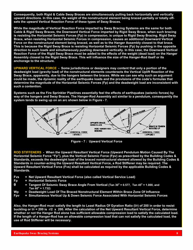
Consequently, both Rigid & Cable Sway Braces are simultaneously pulling back horizontally and vertically upward directions. In this case, the weight of the nonstructural element being braced partially or totally off-sets the upward Vertical Reaction Force of these types of Sway Braces. While the magnitude of Vertical Reaction Force imparted by Sway Bracing Systems are the same for both Cable & Rigid Sway Braces, the Downward Vertical Force imparted by Rigid Sway Brace, when such bracing is resisting the Horizontal Seismic Forces (Fp) in compression, is unique to Rigid Sway Bracing. Rigid Sway Brace, when resisting Horizontal Seismic Forces in compression, causes an additional Downward Vertical Force on the nonstructural element being braced, as well as to the Hanger Assembly closest to that brace. This is because the Rigid Sway Brace is resisting Horizontal Seismic Forces (Fp) by pushing in the opposite direction to such loads and simultaneously pushing downward vertically. In this case, the Downward Vertical Reaction Force of the Rigid Sway Brace must be added to the effects of the weight (dead load) on the Hanger Assembly closest to the Rigid Sway Brace. This will influence the size of the Hanger-Rod itself or its anchorage to the structure. UPWARD VERTICAL FORCE - Some jurisdictions or designers may content that only a portion of the deadweight load (gravity load) of the nonstructural elements counteracts the Vertical Uplift Reaction of the Sway Brace, apparently, due to the hangers between the braces. While we can see why such an argument could be made, the dynamic reality of the earthquake loads and the provisions of the code’s formulas that determine the magnitude of the Horizontal Seismic Forces (Fp) and the deadweight load are inconsistent with such a contention. Systems such as the Fire Sprinkler Pipelines essentially feel the effects of earthquakes (seismic forces) by way of the hangers and Sway Braces. The Hanger-Rod Assembly act similar to a pendulum, consequently the system tends to swing up on an arc shown below in Figure - 7.
Figure - 7 : Upward Vertical Force
ROD STIFFENERS - When the Upward Resultant Vertical Force (Upward Pendulum Motion Caused By The Horizontal Seismic Force “Fp”), plus the Vertical Seismic Force (Fpv) as prescribed by the Building Codes & Standards, exceeds the deadweight load of the braced nonstructural element allowed by the Building Codes & Standards in counter-acting the Upward Resultant Vertical Force, a Rod Stiffener may be required. The Upward Resultant Vertical Force (Fvs) shall be calculated as required by the applicable Building Codes & Standards. Fvs = Net Upward Resultant Vertical Force (also called Vertical Service Load) Fp = Horizontal Seismic Force θ = Tangent Of Seismic Sway Brace Angle From Vertical (Tan 30o = 0.577, Tan 45o = 1.000, and
Tan 60o = 1.732) Wp = Deadweight Load Of The Braced Nonstructural Element Within Brace Zone Of Influence Fpv = Simultaneous Vertical Up & Down Seismic Force Associated With Horizontal Seismic Forces Also, the Hanger-Rod must satisfy the length to Least Radius Of Gyration Ratio (l/r) of 200 in order to resist buckling or l/r = 200 is r/2 x 200. After the calculation of the Net Upward Resultant Vertical Force, determine whether or not the Hanger Rod alone has sufficient allowable compression load to satisfy the calculated load. If the length of a Hanger-Rod has an allowable compression load that can not satisfy the calculated load, the use of Rod Stiffener will be necessary.
Earthquake Sway Bracing Systems 8

Table - 3 : Hanger-Rod With And Without Rod Stiffener As shown above in Table - 3, it is only a representative information, although it could be directly applicable in some circumstances. Because, various manufacturers of Seismic Sway Bracing Systems may publish different values of Maximum Allowable Compression Loads, it is therefore necessary to calculate the Upward Resultant Vertical Force (Upward Pendulum Motion Caused By The Horizontal Seismic Force “Fp”), plus the Seismic Vertical Force (Fpv) as prescribed by the Building Codes & Standards, exceeds the deadweight load of the braced nonstructural element allowed by the Building Codes & Standards in counter-acting the Upward Resultant Vertical Force. In this way, the requirement for Rod Stiffener(s) will be determined if it should be provided or not.
Earthquake Sway Bracing Systems 9
NOTE : Strut Bars, Angle Bars, Flat Bars, Rods, and Pipes (Rigid Sway Braces) act in both Tension and Compression. Their length is restricted by a length to Least Radius Of Gyration Ratio of 200 to reduce the risk of buckling under compression. The Cable Sway Braces are not restricted in length. This
permit the users to make Sway Braces substantially longer at minimal cost while allowing for maximum field adjustments with no impact on bracing strength.
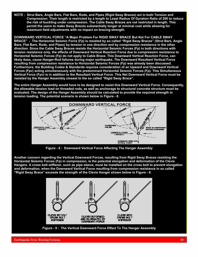
DOWNWARD VERTICAL FORCE “A Major Problem For RIGID SWAY BRACE But Not For CABLE SWAY BRACE” - The Horizontal Seismic Force (Fp) is resisted by so called “Rigid Sway Braces” (Strut Bars, Angle Bars, Flat Bars, Rods, and Pipes) by tension in one direction and by compression resistance in the other direction. Since the Cable Sway Braces resists the Horizontal Seismic Forces (Fp) in both directions with tension resistance only, the effects of Downward Vertical Reaction Force due to compression resistance to Horizontal Seismic Forces (Fp) do not apply to Cable Brace. This Downward Vertical Reaction Force, can likely does, cause Hanger-Rod failures during major earthquake. The Downward Resultant Vertical Force resulting from compression resistance to Horizontal Seismic Forces (Fp) was already been discussed. Furthermore, the Building Codes & Standards requires consideration of an Upward and Downward Vertical Forces (Fpv) acting simultaneously with the predominant Horizontal Seismic Forces (Fp). This Simultaneous Vertical Force (Fpv) is in addition to the Resultant Vertical Force. This Net Downward Vertical Force must be resisted by the Hanger Assembly closest to the so called “Rigid Sway Brace”. The entire Hanger Assembly would have to be designed to resist this Downward Vertical Force. Consequently, the allowable tension load on threaded rods, as well as anchorage to structural concrete structure must be evaluated. The design of the Hanger Assembly should be calculated to provide the required strength in tension loading. The potential scenario is shown below in Figure - 8.
Figure - 8 : Downward Vertical Force Affecting The Hanger Assembly
Another concern regarding the Vertical Downward Forces, resulting from Rigid Sway Braces resisting the Horizontal Seismic Forces (Fp) in compression, is the potential elongation and deformation of the Clevis Hangers. A cross bolt stiffener, such as pipe sleeve, must be installed on the cross bolt to prevent elongation and deformation, when the Downward Vertical Force resulting from compression resistance in so called “Rigid Sway Brace” exceeds the strength of the Clevis Hanger shown below in Figure - 9.
Figure - 9 : The Vertical Downward Force Effect To The Hanger Assembly
Earthquake Sway Bracing Systems 10

PRACTICAL COMPARISON BETWEEN RIGID SWAY BRACE VS. CABLE SWAY BRACE
• The physical weight of the Rigid Sway Brace is heavy and impose additional mechanical loading effect
to the deadweight load of the suspended nonstructural element. While the physical weight of Cable Sway Brace is very light. Below is the physical weight data of the Rigid Sway Braces & Cable Sway Braces.
Note : The physical weight of the Seismic Cable No.: 48 (Color Coded Yellow) = 0.27664 oz. per foot. Rigid Steel Rods available from 1/4” up to 7/8” Ø and larger (0.167 up to 2.00 Lb./Ft.) Rigid Steel Angle Bars are available from 1/2" x 1/2" up to 3” x 3” with thickness from 1/8” up to 1/2" (0.38 up to 9.40 Lb./Ft.) The rigid steel Strut Bars are available from 1-5/8” square form, 1-5/8” x 2-7/16” rectangular form, 1-5/8” x 3-1/4”, & 1-5/8” x 4-7/8” rectangular form welded-joined together (1.89 up to 4.94 Lb./Ft.) Rigid Steel Flat Bars are available from 1/4" x 1/2" up to 3/8” x 3” (0.425 up to 3.83 Lb./Ft.)
• The physical shape of the Rigid Sway Brace can be deformed by seismic forces. While the physical shape of the Cable Sway Brace can not be deformed.
• Several feet long of pre-cut heavy & thick gauge Rigid Sway Brace is very difficult for a single or even
two men to carry and lift it up going to a high location within the building structure where it will be installed and to be attached between the suspended nonstructural element and structural element. Especially, if the area is already congested with other nonstructural elements, such as pipes, air-ducts, and other components. While Cable Sway Brace is very easy to carry by a single man, because it is very light and can be rolled and clipped into his safety belt going up to a high location where installation and attachment will be performed.
• Rigid Sway Brace require a precise measurement and cutting into a required length for the actual
installation and attachment. Being made of high-tensile rigid steel, it need more labor to cut it precisely, angular bending, or welding (hot works) or in short, lots of fabrication works. The result is a high-cost of installation. While the Cable Sway Brace is flexible and very easy to cut by a dedicated cable cutter and very easy to be tailored for the actual installation and attachment. No angular bending or welding (hot works) to be done to the actual cable itself, in short no fabrication works.
Earthquake Sway Bracing Systems 11

• Sub-standard Rigid Sway Braces purchased from local hardware may be difficult to obtain the
specifications and a manufacturing documentation, such as : Rated Tensile & Yield Strength, Thickness Tolerance, Rated Maximum Allowable Load, Material Composition Of Metal, and other manufacturing procedures, (in short a sub-standard materials). Documentation is required for quality assurance and traceability for safety. Usually, it is the Risk Insurer who demand that Sway Braces either Rigid or Cable shall be approved / listed, such as FM Approved or UL Listed and that the manufacturing quality plan is ISO. If the Risk Insurer found out that the Rigid Sway Braces are sub-standard and not approved or listed, a strong possibility that it will be rejected. The Risk Insurers are very intelligent and trained professionals to determine an approved and listed devices and components, particularly if the utmost concern is safety. All concerned parties should know the YES or NO position of the Risk Insurer.
Note : The UL Listed Pre-Stretched Certified Break Strength Wire Rope / Cable TM Braces are fully documented for quality and safety assurance. Again, not all Cables for Sway Bracing Systems which are intended for seismic applications are UL Listed, Pre-Stretched to comply to ASCE 19, and Certified Break Strength.
• Substantial vibrations can travel along the Rigid Sway Brace and transferred it into the suspended nonstructural element or vice-versa. Substantial vibrations can not easily travel along the Cable Sway Brace being flexible and lightweight and in-fact it dampens severe vibrations that will be attenuated further before it reaches into the suspended nonstructural element or vice-versa.
• A 10 feet standard length of approved or listed Rigid Sway Brace + heavy shipping weight + physical
dimensions are more expensive than a pre-cut 10 feet long of flexible and lightweight listed Cable Sway Brace rolled inside a sealed plastic bag.
Below are the comments of the other professionals and manufacturers engaged in the Seismic Sway Bracing Systems concerning the comparison between Rigid Sway Brace & Cable Sway Brace. Both Cable and Rigid Sway Braces have their place in the restraint of piping. In order to minimize costs and speed up installation, the differences between the two should be understood.
In general, piping restrained by Rigid Brace will require only 1 brace per restraint location while piping restrained with Cable Brace requires that 2 cables be fitted forming an “X” or a “V”. As a trade-off, the number of restraint points needed on a given run of piping will typically be considerably higher for a Rigid Sway Brace than for the Cable Sway Brace and, generally, the Rigid Sway Braces will be more costly to install.
An added factor to consider when selecting a restrain systems is that once a decision is reached on the type to use for a particular run, code requirements state that the same type of system must be used for the entire run (all Cable or all Rigid).
The obvious advantage of the Rigid Sway Braces is that, when space is at a premium, Cable Sway Braces angling up to the ceiling on each side of the run make take more space than is available. Rigid Sway Brace can be fitted to one side only, allowing a more narrow packaging arrangement. The advantages of Cable Sway Braces, where they can be used are numerous. First, they can usually be spaced less frequently along a pipe than Rigid Sway Braces. Second, they can not increase the tensile forces in the hanger rod that results from the weight load, so rod and rod anchorage capabilities are not impacted. Third, they are easily set to the proper length. Fourth, they are well-suited to isolated piping applications.
To better explain the differences between the two types of Sway Braces, it is necessary to look at how seismic forces are resisted with Cable or Rigid Sway Braces, as shown in Figure - 10 on the next page.
Earthquake Sway Bracing Systems 12

Figure - 10 : How The Seismic Forces Are Resisted By Cable & Rigid Sway Braces The key factor to note is that Cable Sway Braces can only be loaded in tension. This means that seismic forces can only generate compressive loads in the pipe hanger rod. Seismic forces can, however, load the Rigid Sway Brace in compression resulting in a tensile load on the hanger rod.
This tensile load is in addition to any deadweight load that may already be supported by the hanger and is often significantly higher than the original load. This has the potential to rip the hanger rod out of the support structure and must be considered when sizing components.
Because of this added tensile component and the resulting impact on the necessary hanger rod size, most Rigid Sway Brace manufacturers limit the maximum allowable Rigid Sway Brace angle (to the horizontal) 45 degrees. This is lower than typical allowable angles for Cable Sway Braces that often reach 60 degrees from the horizontal. A summary of the above data, based on a 500Lb. weight per hanger rod (1000 Lb. Per Trapeze Bar) and including concrete sizes minimum embedment is shown below, in Table - 4.
Table - 4 : Tensile Loads Applied To Hanger-Rod By Cable & Rigid Sway Braces
Earthquake Sway Bracing Systems 13

In Figure - 10, on page 13, the Cable Sway Braces (Tension Only) is helping the Hanger-Rod Support Assembly carrying the suspended pipeline or nonstructural element to transfer the imparted Horizontal Seismic Force (Fp) to the anchorage bolted into the structural elements. Whereas, the Rigid Sway Brace (Tension & Compression) is aggravating the Hanger-Rod Support Assembly because of the compression load which impose burden to the tensile strength of the Hanger-Rod Support, thereby lowering the maximum allowable load capacity of the Hanger-Rod Support and will also damage the Clevis Hanger. Also, the Cable Sway Braces are more well-suited to use for suspended pipeline or other suspended nonstructural elements which are Isolated, shown below in Figure - 11.
Figure - 11 : Cable Sway Braces Are Most Appropriate For Suspended-Isolated Pipeline
The physical weight of heavy & thick-gauge and compression load (Downward Force) of a Rigid Sway Brace will aggravate the 1/8” or 1/4" clearance of the Isolated Hanger Assembly. The Cable Sway Braces acting together in Tension on both sides will not aggravate the suspended-isolated pipeline or other nonstructural elements. According from the applicable Building Codes & Standards, the Horizontal Seismic Forces (Fp) shall be doubled (2Fp) for vibration-isolated nonstructural elements. Because, the vibration-isolated nonstructural elements may significantly amplify a series of Horizontal Seismic Forces (Fp) which may come from any direction and the Simultaneous Vertical Up & Down Seismic Force (Fpv). The Rigid Sway Brace can transfer significant forces as mentioned above and even the vibrations to the suspended-isolated nonstructural elements. This is not significant to Cable Sway Braces having very small physical diameter, lightweight, and flexible. Do not combined Rigid Sway Brace to the Cable Sway Brace, is not permitted by the Building Codes & Standards due to mismatch. Another important matter which must be seriously considered or utmost concern is the suspended pipelines which will exhibit large Thermal Expansion / Contraction. That is why steam pipelines, hot water pipelines, and cold water pipelines that will produce large Thermal Expansion / Contraction due to the hot-cold temperature of flowing medium should not be braced longitudinally, for the suspended pipeline will buckle.
Figure - 12 : Suspended Pipelines That Will Exhibit Thermal Expansion / Contraction Should Not Be Braced Longitudinally, Pipeline Will Buckle
Earthquake Sway Bracing Systems 14

The solution is to provide a Flexible Loop having the lowest Spring Rate Force in pounds, even lower than 100 Lbs. or higher. The use of Metal Bellows Expansion Joint is not highly recommended, for it has extremely high Spring Force in thousand of pounds, usually for a 2-1/2” size Metal Bellows Expansion Joint, the minimum Spring Force is 2,600 Lbs. per inch per corrugation and higher for larger sizes. The extremely higher Spring-Rate Force will require extremely high anchor loads which sometimes exceed over the prescribed Sway Bracings maximum allowable loads.
Figure - 13 : Hard Pipe Loop For Suspended Pipeline With Large Thermal Expansion / Contraction
Figure - 14 : Flexible Loop For Thermal Expansion / Contraction Of Suspended Pipeline
NOTE : Hard Pipe Loop physical dimensions (footprint) is extremely large and will require large space for the installation. While a pre-engineered Seismic Spectrum Rated Flexible Loop which also simultaneously compensates the Thermal Expansion / Contraction is 75% smaller in physical dimensions than the Hard Pipe Loop. Hence, it will only require a fraction of space with a very-low Spring Rate Force in pounds.
Being so flexible, it will require 4-Way Sway Braces at both end connections with pipe-clamp slightly loose with sliding clearance to become the point of least resistance to Thermal Expansion / Contraction. Since this is a flexible piping component, the Horizontal Seismic Forces which may come from any direction shall be doubled (2Fp). There are various manufacturers of Sway Bracing Systems, along with the systems design engineers and contractors, where they allow to connect the Sway Braces within the Hanger-Rod (slightly above the Clevis Hanger or Trapeze). Take note that this is contrary to the Sway Brace connections as stipulated by the NFPA-13 Standards. The Sway Brace connections are allowed to be directly connected to the Clevis Hanger with high-tensile pipe sleeve or Clevis Cross-Brace.
Earthquake Sway Bracing Systems 15

This condition is very fascinating, I became so curious if this is true. I therefore made a research about this issue if there are indeed manufacturers, systems design engineers, and contractors who are utilizing the said bracing attachments as stated on page 15 and I’ve found out that it is true.
Figure - 15 : Sway Bracing Attachments Not Conforming To The NFPA-13 Standards
I’m not against the other manufacturers, systems design engineers, and contractors who are utilizing this type of sway bracing connections. But I humbly agree to Kraig Kirschner about the said issue. I decided to patch herein the stipulation made by Mr. Kirschner, also see the color orange arrows.
Earthquake Sway Bracing Systems 16

There are other connections which are at least a maximum of 4 inches away from the Hanger Assembly as shown below in Figure - 16, courtesy of the FEMA / VISCMA / ASCE. This type of connection will not directly influence or burden the entire Hanger Assembly, a wise recommendation was provided by the FEMA / VICSMA / ASCE.
Figure - 16 : Connections Of Sway Braces Which Does Not Directly Influence The Hanger Assembly
Instead the Hanger Support Assembly, it is the main suspended pipeline which is being braced directly, this conform to the provisions of the NFPA-13 Standards.
VERSATILITY OF 4-WAY SWAY BRACES The 4-Way Sway Braces primarily use four braces and only 2-Way Braces for particular purposes. 4-Way Sway Braces would be useful to maintain alignment of small and relatively flexible suspended nonstructural elements. It is highly recommendable that the 4-Way Sway Braces be located at the end of the branch suspended pipeline and that it be sized for the entire branch load, so that the branch line loads do not increase the loads on the sway braces for the main pipeline. The NFPA-13 describes a procedure primarily using Lateral Sway Bracing & Longitudinal Sway Bracing method, which are basically 2-Way Sway Braces and using 4-Sway Braces for particular purposes. This is not to say that NFPA-13 objects the use of 4-Way Sway Braces.
Earthquake Sway Bracing Systems 17

The Building Codes require that the Sway Bracing Systems be capable of bracing the suspended nonstructural elements against the Horizontal Seismic Forces (Fpv) which may come from any direction. The 4-Way Braces will do the job, such that, a separate Lateral & Longitudinal Sway Bracing methods spaced at unequal distances with unequal loads would inherently create UNBALANCED LOADS. These loads vary with the spacing as they skewed to the orientation of the Sway Braces, because the seismic load is shared by the Lateral & Longitudinal Sway Braces. Let us say in a practical way, for a several hundred feet long of suspended pipeline and that the calculated Horizontal Seismic Force (Fp) + Simultaneous Vertical Up & Down Seismic Force (Fpv) + Net Resultant Vertical Force (Fvs) will require 20 units of Lateral Sway Braces @ 30 Feet spacing and 5 units of Longitudinal Sway Braces at @ 80 Feet Spacing. If the 4-Way Sway Braces are to be used to satisfy the seismic provisions of the Building Codes & Standards, the 10 units of equally spaced 4-Way Sway Braces @ 40 Feet long will do the entire job, simple, economical, and satisfied the Building Codes & Standards. Now, since so many systems design engineers, consultants, and contractors are already highly familiar to the Rigid Sway Bracings, let us now see for ourselves what is this UL LISTED PRE-STRETCHED CERTIFIED BREAK STRENGTH SEISMIC WIRE ROPE / CABLE TM BRACING SYSTEMS is all about.
Figure - 17 : UL Listed Pre-Stretched Certified Break Strength Seismic Wire Rope / Cable TM Bracing Components
Earthquake Sway Bracing Systems 18
As we see it by first glance, it seems these Cables can be rolled into spool (drum) or out from the spool, showing that these Cables are highly-flexible and that the shipping weight of the spool as indicated above are 5 Pounds, 8 Pounds, 13 Pounds, and 25 Pounds revealed that these Cables are lightweight.
O.K., these kinds of physical characteristics can not be done to the Rigid Sway Bracing Components.
Furthermore, the length of these Cables per spool is 250 Feet. A 250 Feet long of several 1” x 1” x 1/8” Thick High-Tensile Angle Bars or Strut Bars will reveal that Rigid Sway Braces are indeed heavy and that the shipment and transportation of the Rigid Sway Braces shouldered by the contractors will yield a high-cost.
Therefore, the Cable Sway Braces are more economical and less expensive to handle and shipment transport than Rigid Sway Braces. Because, it is not feasible to roll a high-tensile Rigid Sway Braces.

Table - 5 : Strength Of The UL Listed Pre-Stretched Certified Break Strength Seismic Wire Rope / Cable TM
Figure - 18 : Horizontal Seismic Force And Angles Of Seismic Sway Braces
As always, seismic engineering calculations shall be performed as mandated by the Building Codes & Standards. The results of the calculations will dictate the appropriate spacing of the Lateral & Longitudinal Sway Braces or the implementation of the 4-Way Sway Bracing method, and then to be checked to the Table - 5 as shown above. The HILTI Quick-Bolt TZ is a post-installed mechanical anchor bolts which were evaluated by the IBC / ICC and strength into structural concrete base on the ACI 318-02 Appendix D (Strength Design), another unique and outstanding one is the SIMPSON Strong Bolt “A Wedge Type Self-Undercutting Post-Installed Mechanical Anchor Bolts.” For Hex-Head Stud Anchor Bolts w/ threaded screws & Nuts w/ threaded screws, the ASTM F593C, ASTM F594, ASTM 593G, and ASTM 593H made of 304 / 316 Stainless Steel are the most appropriate fasteners for Structural Steel Beams.
Earthquake Sway Bracing Systems 19

Table - 6
Earthquake Sway Bracing Systems 20

The Table- 6 shown on page 20, are base from the restrictive spacing of Sway Braces as recommended by the SMACNA, NFPA-13, and ASHRAE. Again the actual site conditions and as per results of the load calculations will dictate the most appropriate and practical spacing. We will now see the Material Data of these UL Listed Pre-Stretched Certified Break Strength Seismic Wire Rope / Cable TM Bracing.
Earthquake Sway Bracing Systems 21

Earthquake Sway Bracing Systems 22

The requirements of the SMACNA are somewhat very fascinating. The sizes of their specified Cables are larger than 1/4" Ø, like the 3/8” Ø and 1/2" Ø with Safety Factor of 2 and 5 which somewhat overshoot than the UL Load Rating with Safety Factor of 1.5 and that no manufactured cable by a manufacturer that can achieve a Safety Factor of 5. However, the Kinetics Noise Control seems to meet the minimum requirements of the SMACNA. See Table - 7 below.
Table - 7 : Cable Sizes And Load Ratings Of The Kinetics Noise Control Seismic Cables Meeting The Minimum Requirements Of The SMACNA
Figure - 19 : Kinetics Seismic Cable Restraints
Earthquake Sway Bracing Systems 23

Based from the opinion of other professionals, the 1/2" Ø is already a size of Rod used for Rigid Sway Bracings. Furthermore, are these cables specified by the SMACNA are Pre-Stretched as required by the ASCE 19 . . . . . . . ? If not, it will be a BIG question, because the applicable Building Codes & Standards referenced their requirement from the ASCE 19. Again, in-case the Risk Insurer verify by asking “Is The Cable Pre-Stretched As Per ASCE 19 And Is It Listed . . . ?” Because if not, there is always a big possibility that these cables specified by SMACNA which may not be listed and may not be accepted by the Risk Insurer. Again, the Risk Insurer might reply “Why Are We Going To Insure It If The Systems Are Not Listed For Safety & Quality Assurance, There Will Be No Risk Insurance For Sub-Standard Materials”. Again, the aggravated party will be the contractor who purchased and implement cables which the Risk Insurer might not accept. But hold a minute, there is / are also Risk Insurer(s) who does not accept or recognized UL Listed Cable Sway Bracing methods and they only accept FM Approved or UL Listed Rigid Sway Bracing method. I’ve already experienced this scenario before and I have immediately conferred this matter to one of my colleagues in the United States who is also a long-time and known member of the NFPA-13 Committee, and he was surprised. Despite that the said cables meet and complied the Provisions Of The Building Codes & Standards, the said Risk Insurer did not accept it. It seems they have their own standards which are somewhat superior to the Building Codes & Standards. Despite that the UL Listed Seismic Wire Rope / Cable TM Bracing complied and satisfied the Building Codes & Standards, still the Risk Insurer rejected it. I was also stunned to this scenario even the said seismic cables are by UL Listed and complied to the stringent requirements of the applicable Building Codes & Standards, the risk insurer still rejected it, see below. Now, how about if the Building Officials / Area Having Jurisdiction (AHJ) accepted the UL Listed Seismic Cables and not the FM Approved or UL Listed Rigid Sway Braces for a very special reason . . . ? The building owner will be in the middle of contention, a position which is sometimes difficult to understand.
Earthquake Sway Bracing Systems 24

There is also another important issue which other professionals and Seismic Cable Sway Bracing manufacturers wishes to clarify, where according to them is UNACCEPTABLE CONNECTORS . . . ! Drilled bolt Cable Connections shown below in Figure - 19, exhibit undesirable inconsistencies in capacity if precautions are not taken during the assembly works. Under-tightening, these types of connections results in a loss of frictional capacity while over-tightening cuts into the cable and generates premature cable failures. If used, the only consistent way to properly install cable connectors of this similar type is with the use of a Torque Wrench. Variations of as little of 5 ft-lb. of tightening torque can drop the tensile failure load on the cable by 30% or more. Since the use of torque wrenches or other torque-controlled devices in this field is limited, the level of confidence in the capabilities of these connections is lower than desired for critical seismic applications. Because of the extreme sensitivity of the cable pull strength to the tightening torque of the bolt, drilled cable retention bolts have not been found acceptable by other manufacturers for use as connection hardware.
Figure - 20 : Unacceptable Cable Connectors
Figure - 21 : Example Of Lateral & Longitudinal Seismic Sway Bracings Layout For Suspended Pipeline
Earthquake Sway Bracing Systems 25

Figure - 22 : Example Of Lateral & Longitudinal Seismic Sway Bracings Layout For Suspended Air Duct
Figure - 23 : Seismic Cable Sway Braces For Suspended Nonstructural Elements
Earthquake Sway Bracing Systems 26

SUPPLEMENTAL INFORMATION
1997 UNIFORM BUILDING CODE (UBC) - This is the last edition, this Code was superseded by the International Building Code (IBC). It was found out that the Philippines is adopted to this Code. But the opinion of other professionals may extend their recognition to still use this Code. This Code uses Seismic Zoning from Zone 1 to Zone 4, (Zone 4 is for areas with very strong seismic disturbances). The Philippines was grouped into Seismic Zone 4 by the Tri-Services Manual For Military Constructions based on the UBC. The Horizontal Seismic Forces (Fp) on this Code is based on the Strength Design, also known as Load & Resistance Factor Design (LFRD). This Code has no specific requirement for Vertical Seismic Force (Fpv). However, other professionals who are using this Code provide 1/3 of the Fp will be the Fpv. This Code has specific requirement for the height (locations) of the braced nonstructural elements within the building structures. This Code also has specific requirement for the amplification of seismic forces by flexibly-mounted equipment / components. These are equipment / components mounted into vibration-isolation devices and that the Horizontal Seismic Force shall be doubled (2Fp). This Code also emphasize the importance of Essential Facilities, Hazardous Facilities, Special Occupancy Structures, and Standard Occupancy Structures by designating Occupancy Category I, II, III, and IV with assigned values of Importance Factor (Ip) either 1.0 or 1.50 This Code also emphasize the importance of nonstructural elements by assigning different values of Amplification Factor (Ap) and Response Modification Factor (Rp) which are very crucial for the calculations of the Horizontal Seismic Forces. For complete information, refer to the actual 1997 UBC. 2007 NATIONAL FIRE PROTECTION ASSOCIATION (NFPA-13 STANDARDS) - It was stated by various seismic technical articles that is the intent of the NFPA-13 that all Fire Sprinkler Piping Systems shall be operational before, during, and aftermath of major earthquakes. This Standard on the installation of Automatic Fire Sprinkler Systems is the most universally recognized standard on this subject within the United States. In the Philippines, many systems design engineers and contractors are using this Standard for the design and installations of Automatic Fire Sprinkler Systems. This Standard contains provisions and appendix clarifications on the protection of piping systems against damage where subject to earthquakes which is either referred to or contained within all the Model Codes & Standards. The NFPA-13 is of particular importance because it contains specific information on subjects such as flexibility of connections, penetration of piping through walls and other matters related to the concept of continued operation of the systems after an earthquake. Moreover, this standard provides criteria on the allowable distances between braces, as well as fastener values for anchorage to the structural frame, which are beneficial in the design of the braces & fasteners as well as documenting code compliance. This Standard is based on the Allowable Stress Design (ASD), see page 3. This standard does not address the issue or effect of Simultaneous Vertical Up & Down Seismic Force, Net Resultant Vertical Reaction Force and the amplification of Horizontal Seismic Forces imparted to the flexibly-mounted equipment and flexible-isolated suspended pipelines, which are required by the other latest Building Codes like the IBC, as well as by other Standards such as the ASCE 7 and NEHRP under FEMA, and to include the 1997 UBC. This Standard is a “How To Standard” This Standard addressed the issue of Building Drift (Lateral Deflections In Any Directions) and Differential Movements. But on how to determine and calculate it was not indicated. The UBC, IBC, ASCE, and NEHRP, have analytical and mathematical analysis about this issue. In short, the NFPA-13 stipulated the building drift and differential movement, but did NOT clearly addressed on how to determine the Building Drift & Differential Movement involving analytical & mathematical analysis as the Building Codes does, known as Maximum Allowable Building Drift and the Seismic Relative Displacements.
Earthquake Sway Bracing Systems 27

This Standard has contained various specific exemptions to Hangers that are 6” long or less. Feed and Crossmains supported by Hanger Assembly longer than 6” require Sway Bracing Systems. This Standard is recognized by the 2006 IBC as a Code Complying Standard subject to calculation of the strength of pipe. This Standard is recognized and referenced within all the Codes & other Standards. This standard is also referenced by the UBC. The seismic provisions of the NFPA-13 Standards can not be used to satisfy the requirements of the 2003 IBC. The 2003 IBC does not permit the use of the NFPA-13 Standards seismic provisions. For complete information, refer to the actual 2007 NFPA-13 Standards. 2006 INTERNATIONAL BUILDING CODE (IBC) - This is the latest edition of the IBC, the earlier editions were 2000 & 2003 IBC. This Code is somewhat new in the Philippines. However, there are now many professional systems design engineers and contractors who are using the 2003 and 2006 IBC. This Code now permits the use of the NFPA-13 Standards for Fire Sprinkler Systems. This Code is almost the same as the seismic provisions of the ASCE 7-05 and the 2003 NEHRP, except for other provisions where IBC may differ from the other seismic provisions of the ASCE 7-05 and 2003 NEHRP. This Code uses Site Spectral Response Acceleration (Ss) both 0.2 second Short Period and 1.0 second Period from Ss = 25 up to Ss = 300 instead of using Seismic Zoning 1 to 4 like the UBC. This code uses different values for the nonstructural elements Seismic Spectral Design (SDS) from 0.133 g up to 2.000 g derived from SDS = 2/3 SMS, and where SMS = FaSs. This Code designates Occupancy Category I, II, III, and IV where the earlier 2000 and 2003 editions designates Seismic Use Group I, II, III, and IV. This Code also emphasize the importance of nonstructural elements by assigning different values of Amplification Factor (Ap) and Response Modification Factor (Rp) which are very crucial for the calculations of the Horizontal Seismic Forces (Fp), while the Simultaneous Vertical Up & Down Seismic Force is Fpv = 0.2 SDS Wp. This Code also emphasize the importance of Net Resultant Vertical Reaction Force (Fvs) also being called as Vertical Service Load. The Horizontal Load Factor (HLF) on this Code is 0.7 Fp, where it seems based on the Allowable Stress Design (ASD). But the Minimum, Base, and Maximum Formulas are based on Strength Design. The Cp & Fpw of the NFPA-13 will now comfortable for the IBC 2006. This Code require Sway Bracing for suspended nonstructural elements supported by Hanger Assembly which is longer than 12” long which if justified may develop bending moments. This Code also emphasized the importance of amplification of seismic forces by flexibly-mounted equipment and that Horizontal Seismic Force shall be doubled (2Fp). This Code contains requirements for Qualification & Exemptions for the seismic restraints of nonstructural elements of the building structures. For complete information, refer to the actual 2006 IBC as well as the 2003 IBC. Note : The ASCE 7-05 Minimum Design Loads For Buildings & Structures are almost the same or similar to the current 2006 International Building Code (IBC). There is another latest Code known as the 2006 NFPA 5000 Building Code. 1998 SHEET METAL AND AIRCONDITIONING CONTRACTORS NATIONAL ASSOCIATION (SMACNA) - This Standard is referenced within various Building Codes. The SMACNA publishes a “Seismic Restraint Manual Guidelines For Mechanical Systems”. This Standard was primarily developed to satisfy the requirements of the Title 24 of the California Code Of Regulations (CCR), which includes the OSHPD Code. This Standard initially addressed horizontal loads up to 48% of the weight of the mechanical components. The recent editions increased the horizontal loads. Mechanical systems designed and installed in accordance with
Earthquake Sway Bracing Systems 28

the SMACNA manuals for fabrication and installation of air-ducts and seismic restraints are deemed by the 1997 NEHRP Standard under FEMA, ASCE 7-98 and the 2000 IBC to meet their lateral seismic bracing requirements. ASCE 7-02 indicates that SMACNA Seismic Restraint Manual is an accepted industry standard. While the ASCE 7-05 does not refer to the SMACNA manual. For complete information, refer to the actual 1998 SMACNA as well as the latest edition if there is already.
STRENGTH DESIGN “LOAD AND RESISTANCE FACTOR DESIGN” (LRFD) VS. ALLOWABLE STRESS DESIGN (ASD) - The UL Listed Pre-Stretched Certified Break Strength Seismic Wire Rope / Cable TM Bracing strength design “Load Rating” have used the terms “Safety Factor”, which is normally associated with ASD and LRFD normally associated with strength design. This is because until the 2006 IBC and its referenced 2005 ASCE 7 (ASCE 7-05) provisions, the Codes & Code Referenced Standards were not clear on whether Cable Sway Bracing of nonstructural elements of buildings is required to be designed using a Load Factor of 1.5 applied to full Earthquake Load as related to the strength design or a Safety Factor of 1.5 applied to the design of the bracing to resist 0.7 x the Earthquake Load (Fp) as related to ASD. Consequently, prior to the 2006 IBC utilized the more conservative strength design criteria by applying the Safety / Load Factor to the full earthquake load. The provisions of Section 13.1.7 of the ASCE 7-05, as referenced by the 2006 IBC, have certified that it is appropriate to utilized ASD Criteria with a minimum safety factor of 1.5 as specified in Standards such as NFPA-13 for listed Sway Bracing Systems. It is noted that Fire Sprinkler Systems are assigned the highest Importance Factor (Ip = 1.50) being Life Safety in the Building Codes and Code Referenced Standards such as ASCE 7. This is why the Horizontal Load Factor (HLF) factored the SDS multiplier for the 2006 IBC HLF Tables to reflect the 0.7 Fp - Fpw. The 1,400Lb. Fp using the LFRD is only rated 1,000Lb. in the ASD world. Furthermore, many Sway Bracing components and structural steel components are still based on the Allowable Load for ASD. Even the post-installed anchor bolts are rated into ASD. However, there are some latest post-installed anchor bolts such as the HILTI Kwik Bolt TZ, HSL-3, and HDA Undercut Anchor Bolts and the SIMPSON Strong-Bolt Anchor have published technical data sheets and the ES Report being evaluated by the ICC (promulgator of the IBC) are referenced to the strength design (LRFD) and the calculations of post-installed mechanical anchor bolts into structural concrete are based from the provisions of the ACI 318-02 Appendix D. However, in other sections of their technical data sheets and ES Reports, the ASD data are being shown.
Earthquake Sway Bracing Systems 29

Earthquake Sway Bracing Systems 30
REFERENCES
• Manual Of Code Compliance Guidelines On Earthquake Resistance Of Architectural, Mechanical & Electrical Components & Systems, 2nd Edition Year 2001 and 3rd Edition Year 2008 - Loos & Co., Inc.
• Kinetics Noise Control, Inc. - Seismic Design Manuals
• Addendum No. 1 - September 2000 To Seismic Restraint Manual Guidelines For Mechanical Systems, Second
Edition - Year 1998 - SMACNA.
• Anvil Star Pipe Hangers And Supports - July 2009
• 2000, 2003, & 2000 International Building Code
• ASCE 7-98 (1998) & ASCE 7-05 (2005) Minimum Design Loads For Buildings & Structures
• 1999 & 2007 National Fire Protection Association (NFPA-13 Standards)
• 2000 & 2003 National Earthquake Hazards Reduction Program Under FEMA
• 1997 Uniform Building Code
• Federal Emergency Management Agency (FEMA 414) - Installing Seismic Restraints For Duct And Pipe
• American Concrete Institute - ACI 318-02 Appendix D
• HILTI U.S.A. Post-Installed Mechanical Anchor Bolts
• SIMPSON Strong Anchor Bolt
• ASTM F593 & F594 Hex Head Bolt & Nut Screw For Structural Concrete
• ASCE 19 Structural Application Of Steel Cables For Buildings ACKNOWLEDGEMENT My sincere gratitude to Carl L. Strand, M.S. Geology (president of Strand Earthquake Consultants, L.A. CA. U.S.A. and a member of the ASCE 25-97 Committee) who is my mentor concerning Nonstructural Hazards Mitigation - Seismic Hazards Reduction Program since year 1999 up to this present time, as well as to Dianna Mitchell (manager of the Strand Earthquake Consultants). My sincere appreciation to Albert S. Mendiola (managing director of J. BEAP Industries, Inc.) for his untiring support and my partner for earthquake safety advocacies in the Philippines. Also, to Chester Szalaj and Zeke Bochenek of The Metraflex Co. based in Chicago, IL. concerning the versatility and other technical data of their Seismic Spectrum Rated Flexible Loop. Lastly, my appreciation to Dan Duggan, Jr. of the Seismic Solutions, Inc. CA. U.S.A. and to his father Mr. Daniel C. Duggan Sr. (a member of the NFPA-13 Committee / ASHRAE) & president of Fire Sprinkler Design, St. Louis, Missouri, U.S.A.), as well as to Michael E. Werner, P.E. for their wonderful works for the engineering data concerning the UL Listed Pre-Stretched Certified Break Strength Seismic Wire Rope / Cable TM Bracing Systems. ABOUT THE AUTHOR (From Albert S. Mendiola) The author is Mr. Domingo G. Limeta, Jr. A.E.. (IIT / IET / EE). He gained 15-years of experience in the field of Nonstructural Hazards Mitigation - Seismic Hazards Reduction Program (NHM-SHRP) since 1995, he is the pioneer in the Philippines. His first job experience in this field was handling various Seismic Monitoring & Measuring Precision Instruments and Seismic Gas Shut-Off Valve Systems. He was the first person in the Philippines who introduced and successfully installed various sizes of Seismic Spectrum Rated Flexible Loop manufactured by The Metraflex Co. He was the one who designed and calculated the J-FLEX Seismic V-Loops for UHP Gases now installed and operational at the Texas Instruments manufacturing plant in Clark, Pampanga.

He was the first guy who conducted a seminar in the Philippines about NHM-SHRP entitled “Earthquake Preparedness” to various safety & engineering organizations like : SEIPI - Semiconductor & Electronics Industries In The Philippines, Inc. held at TESDA Bldg., in Taguig City in year 2002. HEMAP - Hospital Engineering & Maintenance Association Of The Philippines held at U.N. Ave., Manila in year 2003, and at the San De Dios Educational Foundation, Inc. (Hospital) in Pasay City in year 2004, and others. Since then, he elevated his knowledge and experience in handling Seismic Sway Bracing Systems of suspended nonstructural elements & Seismic Restraints of various package mechanical & electrical equipment and components, including the preliminary seismic load calculations based from the seismic provisions of the applicable Building Codes & Standards. He has also done several Findings & Reports for the Earthquake Safety & Protection of various American semiconductor manufacturing firms here in the Philippines with coordination with the Risk Insurer Firms. He is now closely working together with various professional engineers, systems design engineers, consultants, contractors, and safety engineers. Lastly, he is also the author of several seismic technical articles and one unpublished book about NHM-SHRP. He is highly familiar about the seismic provisions of various Building Codes & Standards. He is now the Senior Technical Consultant of the J. BEAP Industries, Inc. for NHM-SHRP. ******************************************************************************************************** No part of this material may be reproduced or copied in any forms or by any means – graphic, electronic or mechanical, including photocopying, taping, or information, storage or retrieval systems to be used by other parties for their own purpose or agenda without written permission from the author. This is an intellectual property. All comments or suggestions are welcome for the further improvement of this article. In GOD we trust.
WÉÅ|ÇzÉ ZA _|Åxàt? ]ÜA A.E. (SDT / IIT / IET / EE)
SR. TECHNICAL CONSULTANT FOR NONSTRUCTURAL HAZARDS MITIGATION SEISMIC HAZARDS REDUCTION PROGRAM ********************************************************************************************************
Earthquake Sway Bracing Systems 31