=J A HARCOURT BRACE JOVANOVICH PU (CATION … · ELECTRONICAUGUST 1970 =J A HARCOURT BRACE...
70
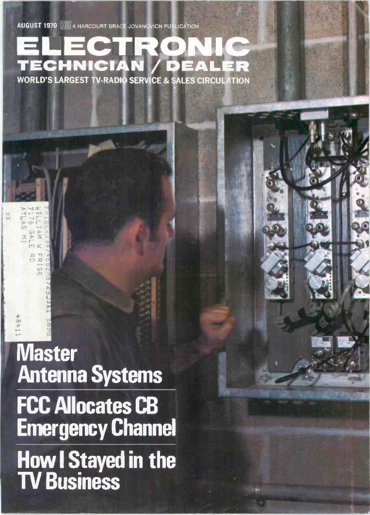
AUGUST 1970 =J A HARCOURT BRACE JOVANOVICH PU (CATION ELECTRONIC TECHNICIAN /DEALER IWORLD'S LARGEST TV-RADI SERVICE & SALES CIRCULATION Master Antenna Systems FCC Allocates CB Emergency Channel How I Stayed in the TV Business
Transcript of =J A HARCOURT BRACE JOVANOVICH PU (CATION … · ELECTRONICAUGUST 1970 =J A HARCOURT BRACE...
AUGUST 1970 =J A HARCOURT BRACE JOVANOVICH PU (CATION
ELECTRONICTECHNICIAN /DEALER
IWORLD'S LARGEST TV-RADI SERVICE & SALES CIRCULATION
MasterAntenna Systems
FCC Allocates CBEmergency Channel
How I Stayed in theTV Business
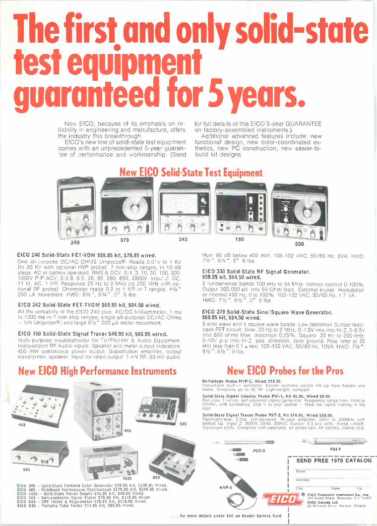
The first and only solid-statetest equipmentguaranteed for 5years.
Now EICO, because of its emphasis on re-liability in engineering and manufacture, offersthe industry this breakthrough.
EICO's new line of solid-state test equipmentcomes with an unprecedented 5 -year guaran-tee of performance and workmanship. (Send
240
for full details of this EICO 5 -year GUARANTEEon factory -assembled instruments.)
Additional advanced features include: newfunctional design, new color -coordinated es-thetics, new PC construction, new easier -to -build kit designs.
New EICO Solid -State Test Equipment
" "ii379 242
EICO 240 Solid -State FET-VOM $59.95 kit, $79.95 wired.One all-purpose DC/AC OHMS Uniprobe®. Reads 0.01V to 1 KV(to 30 KV with optional HVP probe). 7 non -skip ranges, in 10 dBsteps. AC or battery operated. RMS & DCV: 0-1, 3. 10, 30, 100, 300,1000V P -P ACV: 0-2.8, 8.5, 28, 85, 280, 850, 2800V. Input Z: DC,11 M; AC, 1 Mr -2. Response 25 Hz to 2 MHz (to 250 MHz with op-tional RF probe). Ohmmeter reads 0.2 to 1 MO in 7 ranges. 41/2"200 ALA movement. HWD: 81/2", 53/4", 5". 6 lbs.
EICO 242 Solid -State FET-TVOM $69.95 kit, $94.50 wired.All the versatility of the EICO 240 plus: AC/DC Milliammeter, 1 mato 1000 ma in 7 non -skip ranges; single all-purpose DC/AC-Ohms- MA Uniprobe®; and large 6'/2" 200 MA meter movement.
EICO 150 Solid -State Signal Tracer $49.95 kit, $69.95 wired.Multi -purpose troubleshooter for TV/FM/AM & Audio Equipment.Independent RF Audio inputs. Speaker and meter output indicators.400 mW continuous power output. Substitution amplifier, outputtransformer, speaker. Input for rated output: 1 mV RF, 63 mV audio.
New EICO High Performance Instruments
4 4 .J 4*4 I
443
385
465
651 4)41
tt1025 633
tak1/444,1u
EICO 385 - Solid -State Portable Color Generator $79.95 Kit, $109.95 Wired.EICO 465 - Wideband Vectorscope/Oscilloscope $179.95 Kit, $249.95 Wired.EICO 1025 - Solid -State Power Supply $34.95 Kit, $49.95 Wired.EICO 443 - Semiconductor Curve Tracer $79.95 Kit, $119.95 Wired.EICO 633 - CRT Tester & Rejuvenator $79.95 Kit, $119.95 Wired.EICO 635 - Portable Tube Tester $44.95 Kit, $69.95 Wired.
150330
Hum 60 dB below 400 mW. 105-132 VAC, 50/60 Hz. 5VA. HWD:
EICO 330 Solid -State RF Signal Generator.$59.95 kit, $84.50 wired.5 fundamental bands 100 kHz to 54 MHz. Vernier control 0-100%.Output 3C0,000 AJV into 50 -Ohm load. External signal modulationor internal 400 Hz, 0 to 100%. 105-132 VAC. 50/60 Hz. 1.7 VA.HWD: 71/2". 81/2". 5". 5 lbs.
EICO 379 Solid -State Sine/Square Wave Generator.$69.95 kit, $94.50 wired.5 sine wave and 4 square wave bands. Low distortion Sultzer feed-back FET circuit. Sine: 20 Hz to 2 MHz; 0-7.5V rms into hi -Z, 0-6.5Vinto 600 ohms Max. distortion 0.25%. Square: 20 Hz to 200 kHz;0-10V p -p into hi -Z, pos. direction, zero ground. Rise time at 20kHz less than 0.1 µ sec. 105-132 VAC, 50/60 Hz. 10VA. HWD: 71/2",81/2", 81/2". 9 lbs.
New EICO Probes for the ProsHi -Voltage Probe HVP-5, Wired $19.95.Convenient built-in voltmeter. Barrier sections isolate HV tip from handle andmeter. Measures up to 30 KV. Lightweight, compact.
Solid -State Signal Injector Probe PSI -1, Kit $5.95, Wired $9.95.Pen -size, 1 -ounce, self -powered signal generator. Frequency range from I kHz to30MHz, with harmonics. Clip it to your pocket - ideal for signal tracing in thefield.
Solid -State Signal Tracer Probe PST -2, Kit $19.95, Wired $29.95.Flashlight -size, 2.2oz, self -powered. Hi -gain amplifier, 50Hz to 200MHz withdemod tip. Input Z: 35002, 35K11, 350K2; Output: 0.3 p -p volts. Noise -45dB.Distortion <5%. Complete with earphone, all probe tips. AA battery, pocket clip.
`S PST -2<MIMI
<MENI
3711,2
Psi -1
SEND FREE 1970 CATALOG
Narnp
I Address
City State Zip
EICO Eloctronte Instrument Co.' Inc.283 Malta Street. Brooklyn. N Y.11207EICO Canada Ltd.20 Millwick Drive. Weston, Ontario
... for more details circle 108 on Reader Service Card I
ELECTRONICTECHNICIAN / DEALER
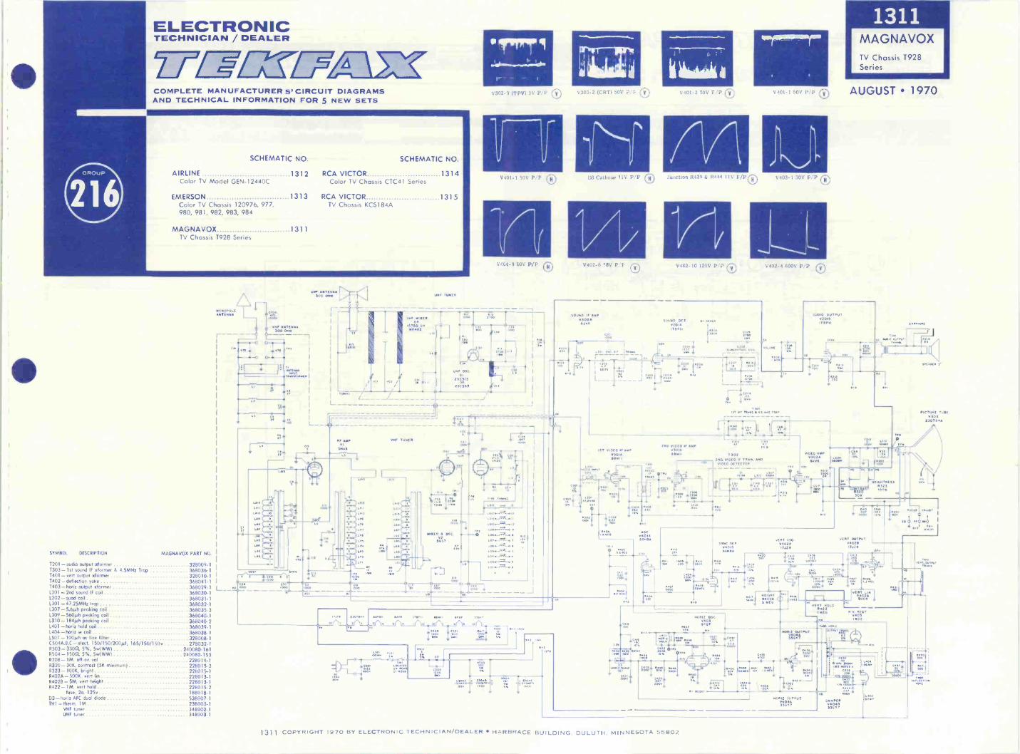
2__IMGM/51COMPLETE MANUFACTURER S' CIRCUIT DIAGRAMSAND TECHNICAL INFORMATION FOR 5 NEW SETS
AIRLINE 1312 RCA VICTOR 1314Color TV Model GEN-12440C Color TV Chassis CTC41 Series
EMERSON 1313 RCA VICTOR 1315Color TV Chassis 120976, 977, TV Chassis KCS184A980, 981, 982, 983, 984
MAGNAVOX 1311TV Chassis T928 Series
1001004 OLEANTENNA
SYMBOL DESCRIPTION MAGNAVOX PART NO.
1201 -audio output ',former 328009-11303 -1st sound IF ',former & 4 5MHz Trap 368036-11401 - vent output ',former 328010-1T402 -deflection yoke 368041-1T403 -honz output :former 368029-1 1._ .1201 -2nd sound IF coil 368030-1L202-quad coil 368031-11301-47.25MHz trop 368032-1L307 - 5.60 pecking coil 368035-31309 - 5609h peaking coil 368040-11310-1840 peaking coil 368040-21401 -horiz hold coil 368039-11404 -horiz w coil 368038-11501 -1000 oc line filter 328008-1C504A,8C - elect, 150/150/200A 165/150/150v 278032-IR503- 33011, 5%. 5w(WW) 240080-1618504-15011. 5%. 5w(WW) 240080-153R208 -1M, off -on vol 228014-1R320- 30K, contrast (5K minimum) 228015-3R323 -100K. bright 228015-1R402A - 500K, vent lin 228013-1R402B - 5M, vent height 228013-1R422- 1M. veil hold 228015-2
fuse. 2a, 125v 188018-1D3- horiz AFC dual diode 538007 1TH1 - therm. IM 238003-1
VHF tuner 348002-1UHF tuner 34E1003-1
IMF ANTENNASOO OM
--0 0
-
,
`.1
umf OEN.300 ONO
r -r
CIS
UM, TIMER
V302- 1 (TPV) 3V P P
V401 -I 50V P P 0
Um, MAUI04
1700 ORm14112
A -AN,A -M -7-b A
1111 N.II.17--/go4 4
C. C. --"C.uroo 1000
---
fw
UmfoeC.T1OR
3513
ZUNI?
if MAPVi
less$$
VIII TIMER
I
IWO CSTS
C3
V303-2 (CRTI 50V : 0
414
Cathoue !IV F P
V402-6 'aiV 1 1
C)
SOUND IF Amp0302eJvP
r""
7TV
C1*S4
GOON
Or
MITER CISCvi
5657
0
774MOO "
- - - - - - _J
L TO. SNO frr T4.111,I COOS
r to
zoi s WeteTIN
g"Aryr
_ .
1ST VINO if AMPV5014Semi
V401-2 70V i,P 0
1311MAGNAVOXTV Chassis 1928Series
V401 -150V P P AUGUST 1970
P7
Junctum R439 a. R44. 11V F PC) V403-1 30V P,P 0
V402-10 125V P P 0
SOUND DE T
V20 in( .04,
12044414
ON: ---E-/rip.
4-410.
44001.7 111.4
1,e.
END VIDEO IF MAP01011Min
In MTV
r
AOC0401A"on
4.- -( -I
( - I ,r) .(s i/n
1001d.
XS
OTPLOCAT.Os OEN
4004 OF .011
trg Cr:i0"vT T
'T
TOT
iT 1.4.171.:1, T.4
V402-4 600V P 0
7,1$7,( Cep
Se
1/010 OUTPUT020111nerll
GIN
4 1
LCPS
10 S
T502250 VIDEO If TRAM AND
V1010 DETECTOR
is64
4`21'TS
4$0:0:17sirol
444.10.1
SOP Arrl IT
4
VIDEO MAPv50246Jve
404
PICTURE TUBEV305
330TH*
r -Cr!POLIV
SIC
17.0
StiPC 414*011
(711114106TMES50523
N .eeSOK
SYNC DEPV4010"MY
vERT 05CV4024
II
VERT OUTPUTV4021
TJZ6
.211
i
11DIONT1140D5S MEI
RORIE OK
4405P07
N C
recw'QF'AWw
C4 0
NS NI.0004
VERT IN
vERT22
1101.0R4
WEE
vo
V. *ACTV4051502
.04
ill
'UT
ier "'Cm.
Mt.. TV SOON
4
sv
11 1100ST
S Sr
"sirPT
1Tip
r.s P.
f -.fl .:4,1 as
0 ri
);.. -r
DAMPERv04336070
WO
01171.[ITres1
1311 COPYRIGHT 1970 BY ELECTRONIC TECHNICIAN/DEALER HA R B RACE BUILDING. DULUTH. MINNESOTA 55802
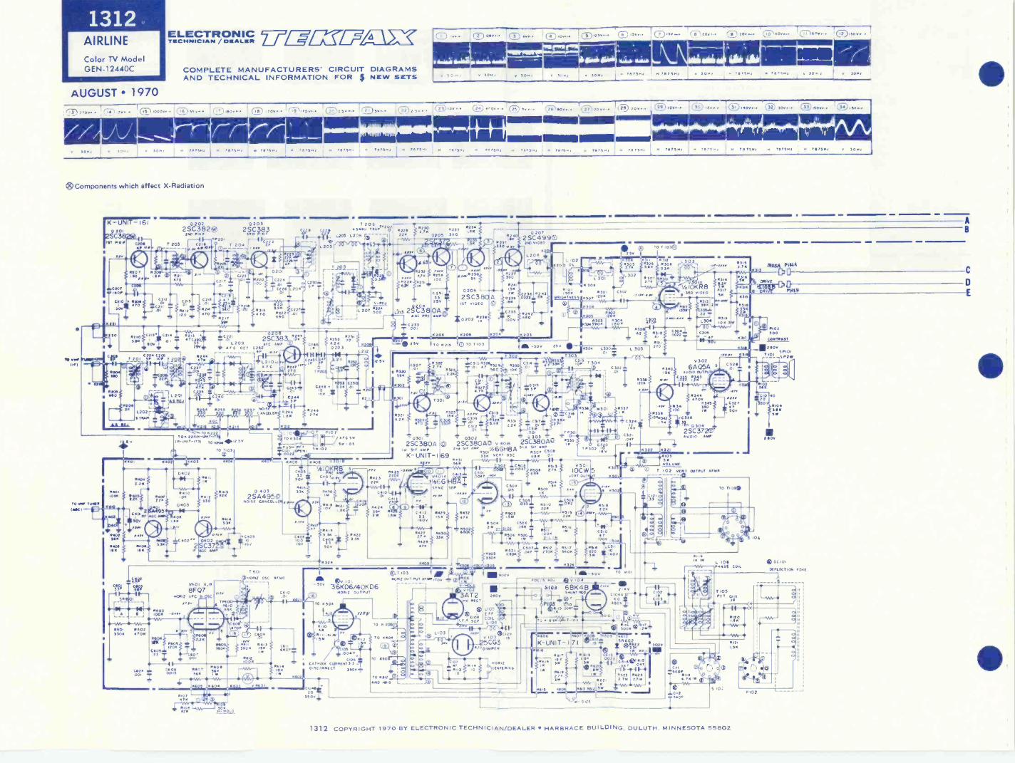
13121 1 1900 .30,
AIRLINE
Color TV ModelGEN-12440C
AUGUST 1970
ELECTRONIC 7/1-w=TECHNICIAN / DEALER
COMPLETE MANUFACTURERS' CIRCUIT DIAGRAMSAND TECHNICAL INFORMATION FOR NEW SETS
11 v V
v TON 4I
v 30v,
l(F-3)'Ov.. CL.D
wig iiiiimoi=1116111111113064
I
v 3068I
V 3064 v 717581I
6 26758, L. 70756: 6 71758, - 7075, 157501I
8 79,588 6 1e133, 15,
®Components which affect X -Radiation
0166
1.1,1
K -UNIT -1610 20,
2Sfr, Mx,
.!Pr
20, zPv
0202 02032SC382® 2SC3Ey260 PIKE 31D
720. 4203
204- 6P
470crag...caw
.41co. *we
Km .001.
1m. C22-
C2,5 C" 4.',c.A. 4"
Coil 1 ::,±oeC'2M T 0
2c, 470 .T.
1.317,
396
-.., .. - RZI)
C202
220 .2,0 C2134
lie1191
;es,,
T 201 CIr T 20
TO ON, TUNE,(MCI
e V
00, 0402
114042 2.
000 f 1s6462
40.1.11150v
V IP8402 00.94.
0403 f TM
L
060, 06023300 470.
0604 4.00. I
2.3
Ti4
CriO_25V
0
C2.; KIN
024
6220
T 206 ,.,C7` C 5... Tom,'
a L200 L.206all
203
0201 -J0224
0,
C22612040.
T;022o
0230
'4722'627
660.0.
Iit.. 20
T 6 5.. T475., v 115.i 76 7 5 81I
0229 1230 0233 66462 1322. 0205 300
S-REJ
goo czi3 2gei 8 GC PIE
C 233T 001
I6'1.201fC DET
2SC383T'0206
4, ,70,,,,:e4.,
C252
I 1-L2.0,2 v f C r, Ft r'"
CL200.
4255
02111 812, .021470 K 222
TO 2240, LOOT,10-L00 -.TM TO K20.2.2252
TO ,03
014
04,2330
011 lOrOK
Ct.IC 40:fr
2
0003
060600.5
C3040
2
7C AMP
1607540
.404
041352.
14.433.
_
8 LER
cr.
C24431
02465.
r.0124°""
004q--- 6406
,76 iizo 371:` K206
HC245C
c
al.. 2 11
).
14 1421L 2
0240 1d.3.33"
:iv _;
4241214
0250Oi
.2,0
P. C
2
VCSO03
0 4032SA495@
30.5E CO...ULLA", 0
Koe
4194RgeC0
C.(103
060056.
160.1.00,2 050 61740
K
06,2.008
060
a
06.4
C53.3500
0406.0 0.0v
14.747
06TO
t2°10 750
C2533250
806
0206
61
TTI 10150 v 757502 71,75.1 V 300:
11.0237330 4,
0 IV4227390
2SC38 A1ST 010E0
10202
024
26R239
0255
00 v
02072 SC4990210 0.0E0
Q
L 200
-t1
C234172.3.0022 04
2
0205 K204 5203
TO 626 070 1.03
10320,
.302
. 30
SS
832O .24
K20
L 30.300
R 130.11.4.01 SS 030, 1200
II -500 250
C3O0)
30,.1±
C 0310
:w.
24.
,2545309
V:.r
1e
10
0301
2SC380AS., 06P
K- UNIT -I
410 4.62
04232211
NANA /-1
CtO21C400""
4.2266 1142C.,,
CD CI9.
29 01.1
01193 3. - 01220106 3.30
500
.324
- 50036K06/40KD6
60812 OuTPuT
TO K504
0425 -*'"6'220.
, .far
C4.2 9429
1602
4"T, I
14161
C,l5.11.63:CcOli06
I.LT:32 i
L7c. 30C,:i .
69
02SC3804046.1 S., AMP 502 ,500
511.
33K
vcIR, T0,010,503I I
O 5.3
WV 1
0047 '1, 60K
.305
0303 0304324310. .00.
V40,4 0413
5%.6G /4SYNC SEP
0 Or 41--
IP-0427 9427 3
14213.31
5409
05
I- CoAsTCOE.CcLARRENT 3.3 -T 3500 _
RIOT
0603 0"
IR.00620
20 _350V
T 1039.000 OUT PuT MR,.
70 2030 O 0O 0O 091T -A.
0 10 1
15.C504 .5.0.5 8509 I V
/ 0
,D Cola Sos
0 2.2K
f11' v's -In'.5 ..-.....-R504 C504 6
VrIVA 11.-C5.0..,
150533011
liZ.; 042 I 220.1 540.W2,.
iC502: 05.2 05,2 05. a
20
1130 304 C306s 2 .3.0 0022
TO 1.03(D
.2' L3037r," 'Trot - 4-r4 13;58
3
.4 KI;KA8 it: >.:34. 310 00020 65'..: f 03,5
O 10
304 C33024 L 30501
50,10CW
...TODT5
K50
1,0.502
IIII 9000
.324
500FOC.76 DJ ay 0 4
-11
C58
1300
4340.5.
T - 47 03.1 CONTRAST00 v
00.
A
1,3-1":1411.5 MEE
03,1131
326
0 t 3441. 470K
4345asr 1341
00
C320
Q 304,
2 SC 372(17AMP
0322 .321111053.VOLUME
0 T 02 VEIT OUTPUT
.33 0
MONO
TO 0101
3 MO+
200 v
L105f
COILL ,04n
5CG3° 0 11.57 II
837118
6104 6E1K4B
11..5 00471,14,
v002CENTER
SHUNT 1420
TO-
KAMM V T 20,0
C
10,1c- C.02 -
60 C.033500
:36
60 ie 40
K -UNIT -171
.617 a6 6 le 1,1
3*'oe:"231.-111--Clc.:21?-4":":62:41'..z. 2 71 2 761
11:2o66,3 66$z 56
11.19Ix (IV L 106W. PNASS CO.L
.LOT370-1
0.101
54.
40
150104
vr
2100
DC1010201201.M TOKE
002
4 73
S
1121
1312 COPYRIGHT 1970 By ELECTRONIC TECHNICIAN/DEALER HARBRACE BUILDING. DULUTH, MINNESOTA 55802
P OT
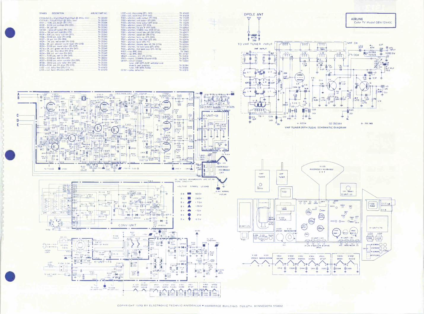
SYMBOL DESCRIPTION AIRLINE PART NO.
C104A,B,C,D - 60µf/20µf/20µf/20µf @ 350v, elect TV 32452C117A,8 - 150µ1/150µf @ 350v, elect TV 32451R101 - 150K, pot, bright (9V-171) TV 25264R102-50012. pot contrast (9V-331) TV 25354R105 - 5K, pot vol TV 25342SW101 -w/on-off switch (9V-229) TV 25342R106- 1M pot vert hold (8V-172) TV 25268R109 - 50K pot, horiz hold (9V-311) TV 25363R126-50011 pot, color (9V-245) TV 25345R127 - 5K pot, tint (9V-223) TV 25346R129- 1M, pot, red screen (9V-205) TV 25343R206 -1K, pot, adjacent sound reject (9V-235) TV 25347R224-50012 pot, sound reject (9V-217) TV 25348R316- 5K, pot, green red drive (9V-241) TV 25349R317- 5K, pot, blue drive (9V-241) TV 25349R504 -2M pot, vert size (9V-241) TV 25349R511 -100K pot. vert hn (9V-241) TV 25349R255- 50011pot, AGC (9V-239) TV 25350R257-50012 pot, noise canceller (9V-239) TV 25350R923 - 50011 pot, color killer (9V-239) TV 25350R952 -500K, pot, 01 drive (9V-239) TV 25350L102 -coil, delay line (2TL-111) TV 61672L105 - coil, horiz efficiency (211-91) TV 61673
999999
SCOOP1 1
ForgP 13u 6S- AMP
6902
74' coo
C903..
24 MP/71404
inn 920
ir-e-V
39
L a
C902 - 6906 C90501 lo I.004/'90'
5.64 SC383 0WTI
0902°
T 90'90050
.903T90 TP9
2I " (0,
0036
49 2130
1107 -coil. degaussing (2TL-161) TV 61680TV 61658
T101- xformer, audio output (7T-193) TV 11239T102- xformer, vert output (8T-209) TV 112971103- xformer, horiz output (8FT-666) TV 11278T106- xformer, power (51-203) TV 11275T201 - xfonner. 1st pm IF (91F-569) TV 624641206- xformer, 4.5MHz trop (91F -571A) TV 62513T301 - xformer, sound take off (TIE -575A) TV 62471T304- xformer, sound det (TIF-573) TV 624741601 xformer, horiz osc (211-980) TV 623341701 xformer. ac line filter (211-69) TV 62476T901 - xformer, burst (2T1-71) TV 624801903 'dormer, chronic take off (TIF-577A) TV 625161904 xformer, Ist bond puss (2T1. -67A) TV 625141905- xformer, 2nd bond pass (211-101A) TV 62515M101 -cap (PRC-366) TV 3465M301 -cap (PRL 381) RV 34107VR601 vanstor, AOC (TS 2171) TV 24238Y901 -crystal, 3.58MHz (Crystal 502) TV 24279CB101 circuit breaker TV 12204
tuner, UHF (UT7-3U2P with/dial corddrum & gear installed) TV 35194tuner, VHF (RT11-7U2A) TV 35206
DC101 - yoke, deflection TV 60218
rl 902 PnaSE SW,Y90. V90.1326
1/2813M11.5° ,1
w
3 5. C914
C9..047
2.613460PaSS40.2,
49,11be
C91504/
1119.7
TO TM 3 0 III 200V
I.
10
R907560
0
190
4126500
COLOR
ot000L.EFIER,
11014"/
C9070047
0903SA49'
COLOR oLir6
923500
KILLER
33P
R927390
L202 -coil. sound trap (91F-565)
111321111/11 .111111167MA... . -TB -117. 627 Si;14RM 300
TINT M ./13v TO 1.103
= 04714C9
0902
6:2300
90
,o21.1.226 6943
69123300
1411jV3V
6934
906
C929OR
R11366.114
0
0906
C930 .2P
0.910
49392 111
00.
L909
1 GRN
GRP 91.0 69'0RED TEL 0109RED ILK 111607
47! 4,170668.1/ e -T lyeREDSINT MR" 1
au la.
RED 91.0
RG 272t.
-1141103
BLu'TEL es
-V/IFT
NTELOCK
0
I.107 104 5,04 00000
.46.151Of 1 9
.91e
4
ee-r2 "V,4
G -r. 11 90950
Kb
CB O
04,6
Ernig 7 sefeti
C 120V60n,
r211
-500472
TO Vw, LmEe11140
S 0
i,,:c :c ..;2 c !re. 78,
090211
1/e BQ CIO
4.,
0942 27Ive
9 945330Kv6.0
C9332033
6945 *274
11/
V 902C4541vs8A00 3300R -y Of/ 1V
C933.033
411.3417.
I V,111-MAr--f 1 Tv -0011 /43
rs.C
s A.7
(MAT OF 410514,
T 701 ...IRRTC. ST.0 512701
02 to vt,tTUNER
Re 04435 07 4.984
#0_3
-413/5.-11911-9-14-1pA.- 22SRBO.0 596018
L BO
=
3P
u.reo.(3)
002
C 0 NV - UNIT
T '06RORER
9904 6
922.09
a?VIA 0,02 KT
'700
0
9-,
8944
2110v
T905.190.
Pen"41
R 0022
0129
R-SCRN
900
L,19 .120 0024 ...0022
11
JL
'5131
G-SCRN- 6750114191 (1021453
K -UNIT -121591 SOI5i
902
50/030 1134
R950200
/sv6.95101941
220 501017.sc-
SCP$902
11160.
'00 seso,e2 111
TO vn7T., 60091111.) CNOKt
25v
290 v -260v
50.52 50.54 50155
KIR 4
9152CO
DC VOF740E MESuIRMENTS ant T3.0. C090.7 nn
C1'4
O 0710
v OL TSGE SYMBOL LEGEND
0713NN. 703 CFO100 M.;
O 709
702 -C70 , 07C4MOr1COV 00VC /04 K - UN IT- I 73
PORT °105E:,
e7 25v
4226 117i1K2020'
6203
2.;01
4724
1,08. svceeee
4205,20r
C3 TOP *IS29v
, 0,
L J 1. -1
970"11/ 203(7090)
TO 027 TO 621.5- urytT- et
07124.?
-2000
SR
C113
BB
B
2
3
B
B5
86
5 6705
C/..0t
F-
512701
56706
"0-11-J
2220-c,..
350
900V
280V
I 700- 260V
500
25V
125V
-2600
6235 6K
4717
C,i5 -C24.7 24.1. 3500 35
L110C100t
671e
.56
To co..
'05
4900V822/490E9022CRT
El 0v 60011.1L
I0C2vOR
TL soFTUNE/1111.1
2600 1700
9,325$02111
6.24270Sw
01254/0Col. 49
'ri so Clue- 350v '50
930v
C,04C20
3500
V , 0336006/0i'06 1-7, 50
v 302 v40, v 30' 0601 EVITO1V 90-2-125C63 10cw5 64052 660139 1009$ BF 07 13B/Ati 1311C10
509 41160 91612
...C35.2 2329' 41: ,C620 C113,1'
*0022 * 0022 * 0022 04. 00220022 = 0,222
DIPOLE ANT
0330
TO VHF TUNER INPUTVW IN RUT
1.'
oon o o
c3 C.28
112P 001
VHF
TUNER
0605.
L- 9C20
3P4 I
RI C 20 v,390K
.00;
001
C 19
AGC H
0
L ,2
IAA
' 0Zirk
C29 47415P *-0-2. C6
C 5 5P
i 56PV
92
C21
H 4
6054 02 25C684
VHF TUNER IRTH-7U2A1 SCHEMATIC DIAGRAM
T PIO C16
10P
R4 R5921x 226
C22
OCA
001
L L
R6600
AIRLINEColor TV Model GEN-12440C
7 UHF CH
SOR
C
5P
unITUNER
7102
01054901291122 / 49000922
C R T
C24
0,00
al
R7470
RI471(
0. ?SC 585
LOP T 71
15196 543(9) U
PC T
C104
0103 010125C 03 36KM/40K
9
C.)K-UN1T -1 69
11 LI Lt
°26
4 -UNIT- 161
V-L1N V-51210/6 13 -DRIVEDRIVE
GC NOISE KILLER GI
v 1031-7750125[03 360060;400.06 iOCW5 61105.4 661.1
V302 V0164 ,003.0Rei
186,001-17 1-1,90191811
C512
5 5 4 5 4 5 5 4
C619C329 C414
12
C934
v 9021134[10
12
C935
392(
I2K
OuT PUT250
C 25
001
COPYRIGHT 1970 BY ELECTRONIC TECHNICIAN/DEALER HARBRACE BUILDING. DULUTH. MINNESOTA 55802

1313EMERSONColor TV Chassis120976, 977, 980,981, 982, 983, 984
-.wee 111111.11,111°
It
I PIN 9,V 207 45V P P2 PIN 8,9 207 40V P P3 PIN 2,9 207 20V P P
wAvEs040E5 4 c 6
yalimaihoom.
5 PIN 2,V 209 609 P P6 P159,9208 409 P P
WAVESIIAPE 7
mOR12ONTAL RATE
7 PIN 6,V-208 650V P -P
8 PIN 1, V208 70v P.P
II PIN 9,V304 2401/P P
111
ELECTRONIC 77/7=EgTECHNICIAN / DEALER
AUGUST 1970COMPLETE MANUFACTURERS' CIRCUIT DIAGRAMSAND TECHNICAL INFORMATION FOR 5 NEW SETS
12 JUNCTION 0306 609 P 1
IS ',ME, V30522 P1651,8 V101 1509 P P
TVC160 Y'
A
0
I
4111
M
201040 01001XI 1001
I
1C201
VIM I0010,111,1104004 nmAle
T-ZOSA T-1011114
icLY 0000
IC -201 NOT USED INT CH 120977,981,983
mftl,T-204
C 212t-r
8.2121ELI1011
AlibukiaLLiia2L1L4
:4;4
1'
1017101O I I, AMP
V-204CONS
40v
5V
L -2031725C IOC 214140
8.2,15
C 2165000
C-213 C 210 110COD COO
C 256081
26056
257j F000 1.2111
4T 11VuT
C-25,47
2040 VIC10 IsT-roy V21:15 T-206
i23, 270940v
69 (C 2170X0
R 217AV150
C 216680
IlTCNIO PAIR
We.84,8°A 1
7532.0.i47
2%0 I. ,15I0
C 222*00
,..... ....,rutyla7sc..;r.cI
71 cp:fa, ,, ,-,.,:,.,71
F;i::::::---T]
1
.§ UHF Twilit 1/14/ TUN/ II1
3,104 30105 A . 181.V.I05 50.17oscA
? IV fOtTO.1141,70, uI41P102 X.10 /14181Artatmlo., &II
D47 -
C -101 0-103
22 -2110V
MAO. cm 'oft
INE10Btom TINY CORM,
MANIA/MT 011EAT3.11LLIS43
.4
An
I
L 101 1-IDIG A125SING
oc
L101 lit as., .44 441
vele ON 005516500
RV 101 RV 02
C11.01CIRCUIT BRIANIIR
11-14:17
OW101A r04.07752110; s.tom 90111.1 co °
Dula 0.1-44111-102
BUIC6 Olt1.21.112
V TO SPE ON $71810POIOPO RADIO
-
l-104440
OvICN-001ICti1110
-101
I
TO T-1010J
i /7I l-i swtoisvi
..ti:01
- SPEAKER SWITCH 12 1
1
'tyro,cm-orrovrron.
lol
[---------[11 1_
cAnvlos Aro,
r keL.106
OW Hill*P-EI
ml ATI RTRANS
101
L.V50511..n
104 0,05
TO PIN II
Q±c.92
0
8
-P C- 200VIDE 0, A F T AND SOUND BOARD
001 859 P P)8 809 PP
P16 9.v .
SO.DT1 0,, SOUND,,
T20; V-201 4C1116
A
C.201
L201
56 U.
V-206 c 22*41.17 15
1.0110220V
I
R 2363 3013
T.
IC
2 TO PIN as
95v
I J83
$00.0,' SOUND 01000
T-202 V-202 6M26
70
R 204 C 205104 c000
1, ...VI,5-201 C _
204 121277
.POD .040 DI'
3:15.r.D12070 1.1,rX tee 1-207
45110 11115
.1509
IMOD DIT nyftsT.203
R 226+270044
2 TWIG
I i::,
01
220 i
1Z 1277 `a_ 75r7.4R 224SELF0 $01JNVREJECT
3R 233700 2
T.6.
Cl*
C 2301 2000
R 2391504
III 2254300
. 270
V206A 116146AO 2., WIC, UGC
-I3V
1209-4.
23
P 24228 2
I
86V
244OK 20
270 V
II2 C
1.11
1I C
I
I
-t29a 227.3 '
210
169..1
AV -203 6AOSAAUDIO OVTINT
V -207A 1511776A V20711.116/4111AItT 91010 ASP (SYNC AGC C0Rg1A AMP
II 231
t 20002
`!f T 8122106
100 o
C 232240
V
199
'`434
270v, 211 360161110110
150V ITOV nC 235lac*
-IV
'AV
1
tRapl°
130V
L-21260g../
110AV- 0 Mt A.
%I2504
33. ,Iti;121
181 77001 55
8
221. 2700
18 5
150V O 234
R 2332470
C 23Y.,1000
300 /4
C 2340
rdr
t84:6
[:11I 247*OA
O 249ktt241
t 900
5,
C3 2
- 270v
C III
10 00 0
SI 701OILS RIC T
007207I0 RICTI 1115 L -10551.102,31.10B 11,110 C.0.1
35090 1759 R 1131000 150
C I06*10
*7, 000 .A 0
*000 WC $08,25007 260 150901
639AC
350v
10C;020403; soo -I
1120vAC 00 at
;PS /till V 9 305 r 302 v 307 V 304
" C-355
9 303
C 556
' -
7000
30,000 opoo4
.,,Tou:PON'INSV110:04
R III$ I 5 0 5
-
...., 50:
31150 ? / 1
V 203 9-207 v 208 v 308 v 306
PgU.1±i0a47,5v,Nv 103 V
92 1519.8.140?) %35
c 3594% 1040:3_1,A. 036 s 5 5 5
\Irrr-- ii120 VAC. 60CPS HEATER STRING
7 7 7
IAD
70 PC 3 PIN 1117
110*
1-2709 SUPPLY
O . - 4 150V SUPPLY
V 2013
v 202
v 204
v 206 v 2055
R14
II 25247
C ;42'50
V-201116 66141111ASYNC SIP
1
-14+1
2532 21116
1459
IR 2545600
50 v
TO T3,IN(R I.
CON TN01C I I
P.104TO SW 301 ON PC 300
C 1137000 tit*
LR
WIN
i 1190114
111 G
I21 2009
afe- 80
Aug SKAR 6L003
ro0006
I .7? -20040
46.4 1°5
C 24,-0.- 41.4.A .C101
t2 2C0v RjR5 1 21:09
000 S.8202cov_T,GALV
e0111 we( S
C7!:08145`1 2009 4-'4 L.802
GplE5y4
NIGHT 5,6
8 BO' Oti4? jw RIGHT R -G V1RT LINeV
I 0
PRI P1OW IO
801*
;7
SOU
IMPORTANT: USE ExACT REPLACEMENT ONLY FOR ACROSSLINE CAPACITOR C -I03 .IMFD I5OV AC. UL
SI 6018 SI 8010*003A C P
2709
-PC 800CONVERGENCE BOARD
,1av
GO
VERIlkulMEP
P 611150 ,
IMOD SI 6010 V[ Venoi1 47
U
TOP V
P660
9,08
tut
O
11-102!Pik IND
B
C
0
4 PIN 2, V305 110. V COMBINATION MODELS ONLX
1313 COPYRIGHT 1970 BY ELECTRONIC TECHNICIAN/DEALER HARBRACE BUILDING, DULUTH. MINNESOTA 55802

AOUTUT 7R
T 10t
11-111147024
C
23 PIN 2.6302 446 FI 4 PIN 6,6302 2509 PP +5 ,i3u135 PIN 9 V302 39
7,74:2
C 52320 1/-301/1 MINIM
IS? DOOM /191/P 2.302
1 TO5/4.4411 0 331 1049
vIOW 3504
2 0V73094
0-1109 WRITI- 3011416
u,y2=00 V -Ilan 1111111111AOUNST 411111
11-3101 301af.0 Olun
0.14.010
301
iTAL le 14"4
1466
c.30914
2.3V
0 SY
N-307 AF11117 I
1600 16 +270., ACC ()VICTOR10
_i8401 84034. +1509
1141.-iso .1. 8:
CIO.S.
T-301 V302A GOMAc.11101 260 C.15014A
samorass 11313 WP
IMAMS3 elrt C 31,0
04V 9,c,co
Ai% 14011 rzgt
CarII
scow
C 522
F
I 121101liNT
14t,z,
78
' 164610
611 5 WM
V
0-303 7.3015053T 711 39412(
a"71.6
C
34170
4
c 50772,8
170
1222.343
_AV
C313
V
1206
142-304
V304AGONSA159 OAC OSC
220V
54447 1
0
2,, PIN 3, 7. 30 1 78 P P P. N 2,93037 7. p p
36 P1111,9302 409 P P27
PIN 2,V307
--PC-300 4.!, 4411.
C.11014 011 1fcT,o6 90 e D4.303 V-303A-SGMSA2" 'MC."
c 316 14207400
5690
Rt367,1,
C 316027200+
-1.5V 2
8.34 t
11-316 C 315 527 10,000 100 2,1
4 2 09
in 321560
t-3043 50 MC 10.13
C.14
C li i'A.
IC 33, l I 14 7264.120 la It1509
vtiqr-
146asoo 345 *
cm 4 5IrC 3112C 333I11 10.000 *2709
31,
660 2200
9551 308488-300
C )47
2200
X-304, 8- SOYNOR PM 4S1 017
,
IE
1-372
1W2200
V305111 %NSA.014.10411M OSC
If -WO 10 LDS91010 OUTPUT
2,39'2 5 V
8.3441110
335000
2309
.2 3.39
P,34 o.+303 9v P
V -50511110111AVamp
C 316j 33
322 t6200 16.
323'20
9V
1 304620740
270*
C If1 4009
r 320,100
126
2v
II 11
'4" tI loll.
I/
29 PIN 9,6307 14. P P
MO
7 87 :2. ,?
II 327V2 /WIG I
Z.
riCAISG 10
ii:4;60V
'1515'
rn 1.1A 2709
68 00326 8-329
64003.331
12 549/
V-30411401411A8.111 C 331
R351320. 55141I11.505A11
G Ana.
639
1- -39
-1289
13 34768
C 331
*DO
I69MY KO14II 7 oi,
410,1.311130v
270v
la 3701000
2709C 557 11-342 C r20
330 gig 3100*5 rig:Cal
I+ .W1--=-1/411-: -Art fi*
., at' t C1 81! * Cji311
I "3.y
v '".4711
L Cr1 41,,,,,,
=V 177 is
8 340';
444.
395 9,8-3972/0.
i0V?
2 70 9
5676577
398fft.
C4M
11 399'00
70 8 .0330
8 393 50
Lupo11 )94335
C 371 20.000
V
40100
X 3 OS
1.°O 9 u1.31
104 OR i2 POLO 106
TO PC 200.08
1.1011DIFLICTiON Y0.1V/ PI 00,5 NOR 2 COILS
11. I 01401111111
0011 001207
7.6
8(0
5 564*2705g
11-307ASONS*r D10,00
2509
kta-1.59
0N
35405
1269
C 342 9914000C
T
35
42%9
$.1SM11 4C 341
6600 2r820
*1,1 e.2
11.'21;8 t
MOP..
2700
61
3132010,
12
3.39
0 3721208
V-3070114/18118 A
n 557-11#
2 2454
3331807
11 -33466000
510 65604
1
180V
Ant
30 PC 300,1ER1A 79,10PIN 3,CRT 140V P P
49051152225 B HP2 219HCP22
4
L
11
.1. kc/1
, Iv
64 : :4 501250v
.8.354 358*335 44 ,101G
-- 2709
0 44
cr------.1911!
2 11/-301
I
ssp.S1159,C1 Sr
400114L
r.
TD61A E"1,JL6_
70 PIN 2'~ 068C200SI Itvic
Cc,
451i19 C '03550
- 130 v
11-301111-1141/1111A01111 OSC
*025308 c 375
022600+
ssig c.ir
,016403 .3.
119 30,
11 371,41C.
J.
n 406 92.
°41C 77 40
1062.503434897" 2
0072109 V
9,691
138
I 2 V
6.3741416
0 375
:A6
401 -10M6018100110
378
1.1,211
11,407
0042 118*2509
229
SC 342 001an
760 '45114:1).
B71
C100 3703*
909
47
11 404150.
11 40522416
808
583:406k
132
Li"212' P. 4712: 2P2A2 V 115
2, 133, :81=5dr
0 -131 P ,J.1 C
I
4I0 .C 3 0,147
...503,1r5v1OM*
4404050 37 50
I,.....L.,30.30: li
1.Liw'''' L ''' 0,441 609
5377 .0 34y.
W.?I
,0. ,
*4.2709
1809
a 1 a 60V
VVO415A
5.11665176 X5114
5 O :
5 Ilyns
500V
311
5.4159 57 1167201 5 6116lag=
CIA: c 322
1-415C3004L'LS=.
"5
"414
2205
104041 444,m1v,I./C 25
IP--1.#45- 0033 /1311
EV' WI*111
so 1.0.0
"sop;
T104NOR 3)78*, IP
1
4.II 141 8-142708 470.
744
I282 2_,_2..
C Ill.--,__-9700 3. S68 C
1 184139
CINTIR D.0121 V103.421C44:191(201:4 0014.15
44 l'= ,' 2 709*
V-1015CUiPICI171111
Cs,,S
3 009
M54085 AI C01.71104 1600C 811 CLOCalt.St 507470*
T70, C08I 11110,091C0111IN DOOM .1011016183508111811
56 SPARK GAP
964151 0111491151 3P1C17110SC/ 11WIC OR MICA CAPAC,I0123 IN tCO
PARA051,01 AND 300 vIlluc 4111 CAPAcoTOPIS IN 4.10110FANADS
1611 AND 400 v.7 V N15157005 iN ON145 KOJI Iran
I)
II 43
40'4;1' 60
FOCUS NCI
iC 121 *11222 IRV 608
5000110 ON 5014
111 146 liviaC 28
46,erriT
31.707
.11 147
15414FOVJS ADJUST
Ti013V1111041Pu1 IMAMS
1,.0.
II
go ,4G
. 115
1:v 2709C 122 0 W
047.111.5
,.100v
. 91 I 0
) 65118 44 0.C
.10
I 0 11 1,4
.0..41110
35 0 v `470 44
2 70 v
0
EMERSONColor TV Chassis 120976, 977,980, 981, 982, 983, 984
31 PC 300,TERM 80,70PIN 7,CRT 112V P P
II
I
in -4044 nI11h n12 '114
32 PC300,TER4 40,TOPIN 12, CRT 160v
33 PIN 2,9306 7.
34 PIN 7, V30690. ;
RESISTANCE READINGS
<wwwwi...,000000000000000CO
<
V
<
0,
<
LP
.4c)
>
<
4:3.
CP
0
>
<r..,
1.....1
0.0
>
<wi.,IQ
-.<<-4
r...,
CO
<43,
<7J,30.
AITT
<
to
IA0
<4.,
AA.-
<4.,
(.2
0.JP
>
</3./
P0
<Nap000-.
<
e
<,,_,%
1...)
<,_,
84
<L.-.
inZ ..<0 r
--0nSr.SITIIIII-ri0*co0coopcocecococe".4cpoLao.14
O.0
>
0
°L
22.
C)
T.
CPC)
24
O.CI
>
28C)
314
CPX1,1C0-pMC
h.n ()
23A54
(14...,C)a.
4.22.3
A0Xa
-1 1< C-$ 0101 RI
1...,
.h.,..
t..)CP7C--.
-.aar...)as7c-
Va7C-4.
0.)0.7C.-.
K)...4X--.
( . J
;,..,..
...I7c-.
-.iy,,-
04.3
0862 2,,X
0.1
8X
'71 ///.
i.44.3
O.m= z
(11
0.c,X
.... 13
Z
,..2
X
R.-..;o:,
-..r A00X
A.aX
A020
K21.,P
X1.01.4.1074
..1044
X-4.
ts,,.
..."--.)1,0A
=4G-iia..
i4,X
K)
.11
.Z.J.
-,3
ti,ii.
34.s.X
_..,.
Z,,,,,1 1
ri_.- Zn1)z
to
X
-.
X
Cr 0 .0.s471(
_-..
-.Cr...-
Ca-- .07","-..
"'6.A
X-.
..2
g'n
oo3
3,
-n
3
3,
-n
3oo03,
-n
303
-n
v1u)e I I
Zn.044 -z
71
03
3.
71
3
3
11
303-
71
o3
3-
11
03
3-
71
173
3-
11
3
3-
71-21
0303-
5,2
-3,2.
-3,3...
3
3.....4,,,,.... -II
3
2-,.
I
I
-n1/a Z
-oO.-Z
.2,27
-y78
-7.
I0t...2a
wc
--.a78-...
.....a.-
3,3- '0
X
ZC
t.X
-.
_...x
:12 P0.
IZ..12,.
X 8.-..
,-;,.x
0.8x .7.,
....x
2:20c, a
_.,c
.
,,=:
:n
I ittr- 0. =1/
&.
-P24.072
1,....:"
;x 00Vx2,..2 .2.,070z-..
-1'
,_l7C
vX
00X 0 = 0 .
X1-1
V0--00 C5
X_,
00 430 00 .00,--Ii4X
7-4
X--
1 1 1 1 1
Zn Zft p
Z(")
1:1Co Z
--.
a i ','eX
i °OooK,oX0Kj
X
'.1 CI'
Xolliii zn 1
0 ilX
1 1 1 1 I 1 1 1 1 I I 1 I 1 I 1
Z(1 1 1 1
... 130 X
IIIIIIIIIIIIIIII--,-III -..)'21-i
1 1 1 1 1 1 1 1 1 1 1 1 1 1 1 1
V.2.201X
1 1
,... 11
1.3 i
I 1 I 1 1 I I 1 I I 1 I I I 1 IL.;--.
1 I I
_, 1314 E
1 I I I I I I I I I I I I I I IrIil-. 1 I 46. i
COPYRIGHT 1970 BY ELECTRONIC TECHNICIAN/DEALER HARBRACE BUILDING. DULUTH. MINNESOTA 55802
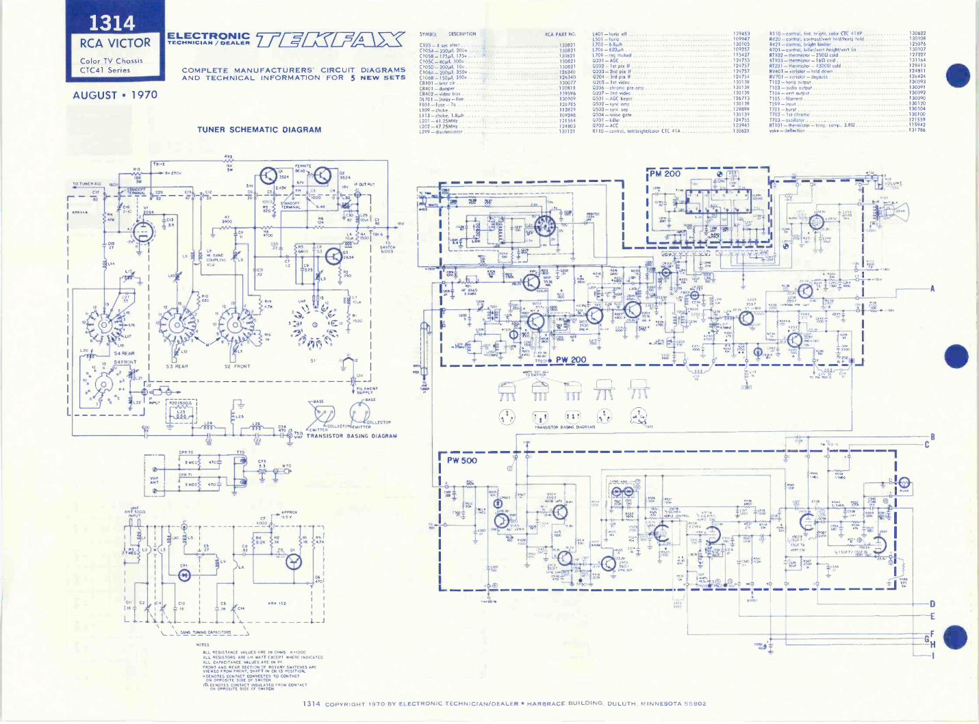
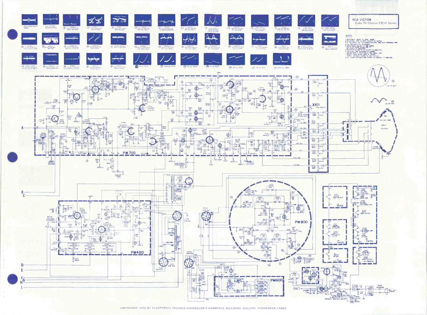
1314RCA VICTORColor TV ChassisCTC41 Series
AUGUST 1970
ELECTRONIC TRW=TECHNICIAN / DEALER
COMPLETE MANUFACTURERS' CIRCUIT DIAGRAMSAND TECHNICAL INFORMATION FOR 5 NEW SETS
TUNER SCHEMATIC DIAGRAM
761-3R13
B. 270V16K
TO TuNER AGC *Ov3v,
STANDOFFCu ,,- TERmINAL
7 - 92 d- -J- - 7I IC* : VI
r 2-10 1 2054
L
KRK144
4711
10.
LI3
L15
L16
17
LIB
S4 REAR
S4 FRONT
.203
L
oa
8
C19
10
L
9
L9
LIO
7 6
L12
53 REAR
je(-'26
*5L22 I INPUT ir R2015008
L23
I -.0 Q k. 25
R93
16KSW
31v
C12 C64 CS(73- -000
R5820
R73900
LBHI BANDCOUPLINGADJ
RIO680
10
52 FRONT
C2039
UHFANT soon
INPUT
217 ME
CII
118
L
0VHFANT
31
.82
--- L26
,000,-1 1 E'enC2I C2282 82
CPR 70 T70
3 MEG
CPR 7
3 MEG
47°T
4701 I
LI I I
L2 1 ML L3
C2
T
10 LS I
CS1 27
CR1 I
IC4 1C10IC9
Tle 6
\ I
\ _GANG TUNING CAPACITORS
NOTES
C892
C14
47
Re4700
01
3524
2 450
C3322
023524
,e0 IF 0./1 PUT
TPI . C3 C4 .
O
0..7012 o L30
STANDOFFrERMINAL 6.48
CT12
R6120
R3 IC86800 13
C9--525
31119 umF
-3 0 OCIO
1116l0
1.
5
(Pi8
12
L29,o.nI CI
82
L; ,8
.11500
St 10 12
BASE
7111 6
TOSWITCH51003
CI4
FFILAMENTSUPPLY
BASE
COLLECTORC34470 .13 EMITTERCOLLECTOR EMITTER
'VII TRANSISTOR BASING DIAGRAM
C7333 *70
C,
KRK 152
RI R5 I
470
4701
I
I
I
I I
I I
ALL RESISTANCE VALUES ARE IN OHMS 0.1000ALL RESISTORS ARE 1/4 WATT EXCEPT WHERE INDICATEDALL CAPACITANCE VALUES ARE IN PFFRONT AND REAR SECTION OF ROTARY SWITCHES AREVIEWED FROM FRONT, SHAFT IN CH 13 POSITION°DENOTES CONTACT CONNECTED TO CONTACT
ON OPPOSITE SIDE OF SWITCHAl DENOTES CONTACT INSULATED FROM CONTACT
ON OPPOSITE SIDE OF SWITCH
SYMBOL DESCRIPTION
C105-4 sec elect ................................. 130821C105A _290W, 200v ....... ............................ 130821C1058-17524 175v ...... - ........................... 130821C105C - 300v ................................... 130821C105D-200µf, 10v ................................ 130821C 106A - 2008f, 350v .................................. 126340C1068- 1508f, 350v ................................. 126340CB101- brkr cir ................. 130077CR401 -damper 120818CR402- video bias 11959601701 -Delay -line 130109
120785112829
L113 -choke, 1.8mh 1092481201 -41.25MHz 1215641202-47.25MHz 124803L299 -discriminator 130121
F101 -Fuse-701109 -choke
PIO
RCA PART NO. 1401 - horiz eft 1294531501 - horiz 109947
1703-6.8291 130105L706 - 6208h 1092571709 -reg mutual 1154270201 -AGC 1247530202 - 1st pix IF 1247570203 -2nd pix IF 1247570204 -3rd pm IF 1247540205 -1st video 1301390206 -chroino pre -amp 1301390207 -2nd video 1301390501 -AGC keyer 126713
0502 -sync amp 130139
0503 -sync sep 1298990504 -noise gate 1301390701 -killer 1247550702 -ACC 123941R110 - control, tint/bright/color CTC 41A 130621
Yen J.W8
504
IT
L
ErIQm IA BIAS0, I 2.5110
I CNN
rPW 500
'4254I _
L
020.5536
C.2MeID
142ffF-
6
cx.sIcco
42of ,PC'S -406v
TP2o1111 pw 200TOCII4D3'rtot
on
TRANSISTOR BANG WORMS
C2.5
.0001_
FM 200
1043576
NCI
3200
C231.000
Lr000-1
43/.5 437 L,ma_i_0, co ,
ID rem
00
02053597
or ..no
6 -.141 . 2co'
ti .41=. SIM
090
11110 -control, tint, bright, color CTC 41XP 130622R420 -control, contrast/vent hold/horiz hold 130108R421 control, bright limiter 125076R701 -control, killerivert height/vent lin 130107RTI02 thermistor 25021 cold 127227RT103 - thermistor -1622 cold 131164R1201 - thermistor -430022 cold 128413RV401 - voristor - hold down 124811RV701 - varistor -degouss 126424T102 - horiz output 1300931.103 -audio output 130091T104- vert output 1300921105 - filament 130090T299 - input 130120T701 -burst 1301041702 -1st chromo 1301001703 - oscillator 121559RTIO1 - thermistor - temp. comp., 3.80 115942yoke - deflection 131786
INN4IMOr.
O
2.4.:,0 0471.
.60
Ise2.0v
352o9706
AtzC.dit
61
3/ 1 1240 CNN56 I 10:03_
4,7VOLUME
_ I T.0310,0Cw.
01
N 1300
,021,K """
cara/ 44
.253 10
'.03 c I CT I
rz
9 '7.....0JI. 245
N, _
202
26.
0.c,
MO e'1,
4lem ..E. li .
44Q3_, Poi'j
111 ro.41,10 T
/ 0
Ny., 10,2
125 I NON'
I2200
z 0.
4,4
C440
711'.165.446.4.-)
40'.! .52,.NN.
.51- r.ei.8.4524,.54
N1.1.13A
, ma,
'200 4 4
5
250,4
*OW NC ...t..2001100 irte
536 8A
145202 2 MEG
,1 ..5P-17;i N
44.
---ra.
09-11503 R501=4, .M4
:5215505
0520 1 X20
NO .0 OE u0Nom Roam. ima =ER imm
100S
40
I
I
1314 COPYRIGHT 1970 BY ELECTRONIC TECHNICIAN/DEALER HARBRACE BUILDING, DULUTH. MINNESOTA 55802
PIN 2 0401 GOV.1/01112
L7.
0.11144M1111.
1.1111, 4,01TOM. 1101112 1.10111C.) 200 141.111.
Paolo PPG flopOt
S4 1. rOOi.Vw2.
0 Cr.; t'torNom (4 10P rrtto.mt Pogo @ GOP ;TOM't.s MVOMemo moot to PMMill 0 00000 yr, cm.r0 4.,....n
I
A 16
BC
0E
I
Of.
RT.2.2120
<Ai011,
1.7MOW .COLOR
VERT.L iN1. .
.0
11111
.4 I/
0 72=-4-
NolifoltION
@ 4:211.: MON0Atod Opt.,
/OS TO
4C136GU., A.ne
46.514
-CM
02
MO, TO , .31054 r
133i 5Z(44Po 0 .366.48.4
MT 0011.4 NIP$.
.ro KO -I 1, '
I GO 1 I
gil.----- -.-1 ownw
MG /L__ ..--1-. : 1 7,
":"..a. 4
-1 °1.
' --3_
c.::,,, --,,z..1 0, i,
7.;',;., _I ' 4- ''' L._ _Li
NW. WW10
9
W106CAT NOCK
T
4*(1ECOTO
4,04A
,2600.1DO WO. W.
C 2020
.--11114r..11,24
.100 S
9V40 VERT
703
101,11.6
270
:1;1'_
14420
vS02.0 .0".", mil.$2.4 NT, Navy.4
arg:r.s.4 Ay Mtg.
11024 Vr.
'my 1.vvm !WeCori.. Min 0
I00077204.152..11- Os.
.000 VIRT
9 7,.,72.i7.:*"
2113141 t llul'lti
181 ST ;Tv:4/.11 T
9 211. yE.1
AININ= IMM BIM GEM MIN
021 ee
it" --,44
I - :;4`0$a42044
)1I /MT
: ,031,,49CP""
..$ 1r.
'O
T NT
To 04000-.3
tn,47'3tr
5,24Cg11
tem- g TW'WW0.1.17706
0 01, '0"
O
10'
N MI
1.4412-1,
0. pw 700 72702
COLOR 7-11V1V-
046.
V1610164INAMLEP
tl
.,wog
LAG
.4E.G4*
,3.3 YIP
14)0111154$.0
7;,.S CZNAP.4,02
eSCP,11. (Atm LI wort Woo
11+0700 pp APT
(3 0 Ott it . LI PamM.. ram. Oomiloto
4 4
PeCIP pP 04.12
22II44.3
NNE SOCKET
8 Mt...4"1:mom Mt.. POmm
7.11=MIT
gANR,....111411.11
I
Iwig IWOO 'W.1.
II
RCA VICTORColor TV Chassis CTC41 Series
NOTES:
WIEMTAIM MIS 03 0.4. DOM2.4250,04.3 1,2'2011 (140141 r NOTED.11 NoCartS 301.24520IEDER.1. PV 201. 4.40.10:1 DOM4 002.24 21. TO.OUNCI.OMMOTANCI 48..211.0 DO 41.45
4. 0091 gre t/c1T0002,04eg10MM.
S. Uss taC2.7. 001180[5 *RI .2M.° II) Male
52R0114 OTT. VOL TOMUTS, IMO WW1 YeDODO 024.0 on. 20% AT RATEDS./..LT VOLTAGE. 10.0 TO 0. 4037+03.
NM. 11010.3 DOW. 5 MO., 13 404210N.
17027
. .2420
0710
11,401*\ VI
GRIM 4700Wo. 7K1670 01010
27,, /IMO% 23.2,0.
17.x4fTMr a TV
_ C,1417/41".-4, 240 cf...L ,
' .3 1'. ,..°17111
, 00
III a M al = MEI IMP = IR W Mg MI MI NMI8$,420OP 0, - 1D 0II ' ....
.1ei
.0 50 00
2
ivn'
.,:.:,.,._.....,..
es
,71TA
3_4402---...-0020 DD. . '2 , 5 / 011052 TA.
l%ill; I ''''''` ''''' i '""
Iv
1:6 , is<
'
1
,r2) -77._
_I
$474:22%
I ,1/
_v_ Inq7< _4.1 .1,1'P
14 i ___.;
' 1. )--- MP . WOo
'''W, II /LI =g
rIlr \\ I,:=,\...)
.50 PP MT
4T3414, 5.1
To I'Por200 0 4 j
BRGPMMESS .,,':sc. 1,,o.
CT=1".
1D;;
T
11MIIMIIMI WW1 11111111MIVIIIEWInnr 111
0
44.02_`^
4%!, 333r
.00
/103-111
TO
TV,00v ....
.00
4.4.002
v402
31L0640440...TuT
Og
t'oNlrs
. .134r
011610T111
t.swErg
........., 00 01c,v.. - , v:Mr'
IVI--
I312: TO
17.0L374411STVEDT1303..0 NANO D 2 .023
CANER .0. t_ -V1Y"
i. k...-- ..,-..... PVI4 00. j
MOAt II210
II
..., :f,:.:
...
':;.-1:-LI:sc''''7:1",....,-,:::42;1:kril.-0- -cr.,'
'-1`12:- .ce.'-'
17
...g.400 4.1 `..., 140/4L01
v.... . 2.,...2.4641.Ga. -4-4,F,'.. irl
$
0.00050.0
I
.130.4.254 70124)1
a.
2002nE t.
L _ _
I.1
sET .1t101.0
P1100,
;:413214 riZApes
<3.1. BLUSC.
i .: 5121
411 TO 1,1000-S '10MOM 11111.1 I=1 I.
11,41$
I)2144 2_10125
11100
S1100
.4_5012, I
I MOO c12111 I11129IMO
t_44.211 I
1,24C0
SCRSCR
r T. 1tom MT
TOG
REDSCR
I
-414,11112,
I
Id1
too' 14.0.641.
LOOS \4000,_3Tirr.... .0T.$2
110..1
e41011 111. audq 0119
MLINT ..NES
%go,
O
kani `Igt107 M./
LPIES
111/4
RMD
1- IA -
Ca.Ns 02.
11110/0.00512 04E5
1.04.20.95
LOT 1110/8.121, LiNES
C0
L1054r -06 -1
100,
Zir444get 000
*SO
110,rOM7
CASE $
$
SSO110,VENT LAM
PW 800r
KG*,
4E01
//GPM 710.0
_L._c TOO. 11S2.
L
21r 03
fDta-
20201
MOO OuntrI
RWIJ
ro1.101:103
.3.31,2
rPAW, WTO 114.
221,11A
s.eeiz mrower
m PW400
20 vAE
.S102lk LIM 'Mu:.
"711P'0,1111AL
1.700-3 W... &Vow
- r
COPYRIGHT 1970 BY ELECTRONIC TECHNICIAN/DEALER HARBRACE BUILDING. DULUTH. MINNESOTA 55802
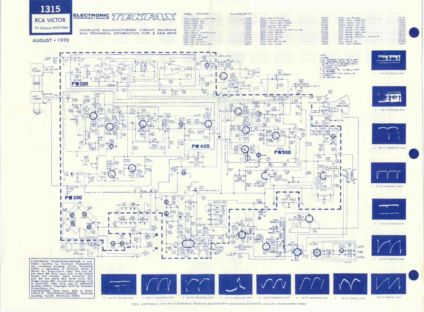
1315RCA VICTORTV Chassis KCS184A
AUGUST 1970
VHF ANT.TEMA.
ELECTRONIC 7 /17=TECHNICIAN /
COMPLETE MANUFACTURERS' CIRCUIT DIAGRAMSAND TECHNICAL INFORMATION FOR 5 NEW SETS
SYMBOL DESCRIPTION RCA VICTOR PART NO.
C101 -capacitor -4 section elect 129099C 101A -250µI,200+ 129099C1018-6501.0, 175+ 129099C101C- 300.if, 175v 129099C10113_100, 150v 129099F101 -fuse -5o 118969IC301 - circuit -integrated. sound 1298711101 -choke-line 114293I.103 -choke- RV 8.2i.th 1073851201 -coil - 40MHz 125129L402 -coil -47.25 trap 1316551.404-coil - RF choke, 2.7z.ih 129703
145V R1a fi 22r31.01 C309
1.045600
4 Ic"
C3R4
C302308
SOUND
.67v
402
T401
IT
pisx-rIF IS040,3535 P
41012.37v
00
C4371-4--.11000
0.40I §1
0405
8I197: C40111000
I -
11421)7500
IF AGCAD.J
11.3 TT -711<1<8 lic4k4 ;he
TO T4uF7102.2 .1.5011
Loco271M
-,T4ori____ cfis70L6L40311,_.__roto7i
' T403_.0403 10.9v
C4Ir , , 35,37 To_a_c34193 or,..2:30271.
4CO
415 It.T---405° .. --14°.
PIX IF6415100
C202.047 R201
+100K
2.311V 0.
C223 AM1000
P1111200
ELECTRONIC TECHNICIAN/DEALER is pub-lished monthly by Harbrace Publications,Inc., Harbrace Building, Duluth, Minnesota55802, a subsidiary of Harcourt, Brace &World, Inc. Subscription rates: One year $5,two years $8, three years $10, in the UnitedStates and Canada. Other countries: Oneyear $9, two years $14, three years $18.Single copies 6001. Second class postage paidat Dansville, New York and at additionalmailing offices. Copyright 1970 by HarbracePublications, Inc.POSTMASTER: Send Form 3579 to ELEC-TRONIC TECHNICIAN/DEALER, HarbraceBuilding, Duluth, Minnesota 55802.
PT
04053569AG.C.AMP
11.419
8426100
I2V8427470C
2.423
,StS
v201 v202vERT. Cur. HOW 05C
?1A1 -1/N,,,,11°
0103 v101H Ofie NOIZ +104DAMPER 0.,TPUT KAMM
627RIO?
SriANN,
1.01113
Al?
Ti001:1
..4188
RAIL560U
A
0421
i000T
10417
560
C204 R202tuF 100K200
C425TOGO
C205.022
R20315f1
042047
0104,VIDEO DRIVER
LAOSI L407
357936um I 2.7Um
PW 4002
1411>-=.20,1z1.YC
v,cogiAs
11.11V
140237
011.1
12V
R10131200122W
ZOi
J-
C2043- 021482 TR4 8200
TO. 145v
T104
0101
3520AUDIO
OUTPUT_ rMVOLUME
CI
RNA6800
2.w 7v
<-
/8208100
2
3
R234
VEMLIN 02018
t 8 VERT CISelack I/2 NLRB
52V
DO NOTTO MEASURE
0k4;7118P<T0A .27 , I 184 32V
1504 200 A ---MAP
I Ir.-
1393 laTi110218
60.4V c2209i3g9
WillI' 81C9
2
47 -my36V
R102
12C:Cv C2I3 PUMI R225 HORIZ
jINSTANT
5101-La I33C0 27K
HOLDAP 5 TO 64/-1W---
PIC L_ iCD56214,_ 12F05.73,,0.000,21,
5.8 3-9, TOPw200-5 2111
2200
14516,
14 300V P -P VERTICAL RATE
cxF
rn13 110V P -P HORIZONTAL RATE 12 35V P -P HORIZONTAL RATE
ov
H011eCIUTPUT33JR6
AI
O41)..q09°0504 250010
i.4Tv
357
1.501-coils-IF, 4.5 trap 128457PW300- circuit -sound module 129702PW400- circuit - video IF module 131952PW500 -circuit - video module 131951R102-2711 10%, 3w, film 129693R115 -control, contrast. vert hold, horn hold 131795R208 - control video bios 131466R234-control wort lin 121223R240-control vert size 121223R429-control AGC 126347R514 - 6.8K 10%, 3w, film 105662RF201 -fuse- resistor 121086
CR50
CR502\4 (7)
RI ISC
CONTRAST
81.401 - coil - RF choke 131791RT401 - therm - 430011 cold 124813RV201 - voristor -48v, lma 118506RV202 - varistor -80v, lma 131652T102- xfonner-horiz output 1319561103- xformer-vert output 131633
11111T104 - xfonner -audio output 1297151301- xfonner-deductor 1267381302- xformer -discriminator, sod Coke off 1297071401 coil-IF 1314651403- xformer -IF 131656RT101- yoke-deflection 124245
801E5L -40002.ALL REWNICE VALUES AAE IN OHMS.3. ALL CAPACiTANCE ALuE5 LESS THAN
LO ARE IN IF, 1.0 AND ABOVE ARE INPF, EXCEPT AS mADICAEO.
4. INMATES 5%.S.:v.4E0.5NC: ARE 1/2 WATT, EACEAT
C. FOR E04.8PAV.IT 1E57 POINTS, SEEE 1433843.
7. IN INDICATES 2%4104IooK
BRIGHTNESSvC4-1,7
VIDEO
PW5005
TOT 102-740-YL
p236CO22 8a38
-443V .068 228.,(DR240
3504VERT SIZE ,
Ac
C 104C -SOLIF:y1756.6 _L
z
8244IOMP4
8242
NEM16111
R1156T5011
I VERT HOLD IA
V102HV RECT
183GT/63GT
PliT°2°D-AG111M4130%-
7102
II 45V P -P HORIZONTAL RATE
R1121.011
TO TM5V
R1051500
70v
70P82200 -N2
1-7JITO cr5iPW200-65
-2w
3
TO To145v 710211
ImmeT 0 AGI du VO-t-48-1I
8250 8249 R248 CO'"3314
4.4.8 I415C5 -el22
FA/201
IiitvA
3104I9VA.P4
KNESCCPE
140V
0224
.033ii58 gclAIx.
06}ti 4ATO
82451004
C.cffn(13l-± I
62431000
-12.3020IAV RT
OUI/2 3ILKI
AS Rit31000
30
DO NOTHEASuR11
RN' 'TEL27K
TK) v..
rri10 13V P -P HORIZONTAL RATE 9 10V P -P HORIZONTAL RATE
VyHooRKEERTizI
C24127.
"IPNTIT'F'TV
1 5V PP VERTICAL RATE
2 50V P -P VERTICAL RATE
3 23V P -P HORIZONTAL RATE
1 r -r4 27V P -P HORIZONTAL RATE
rx..wwFar
S 18V PP VERTICAL RATE
6 160V P -P VERTICAt RATE
7 25V P -P VERTICAL RATE
1315 COPYRIGHT 1970 BY ELECTRONIC TECHNICIAN/DEALER HARBRACE BUILDING, DULUTH. MINNESOTA 55802
10V P -P VERTICAL RATE
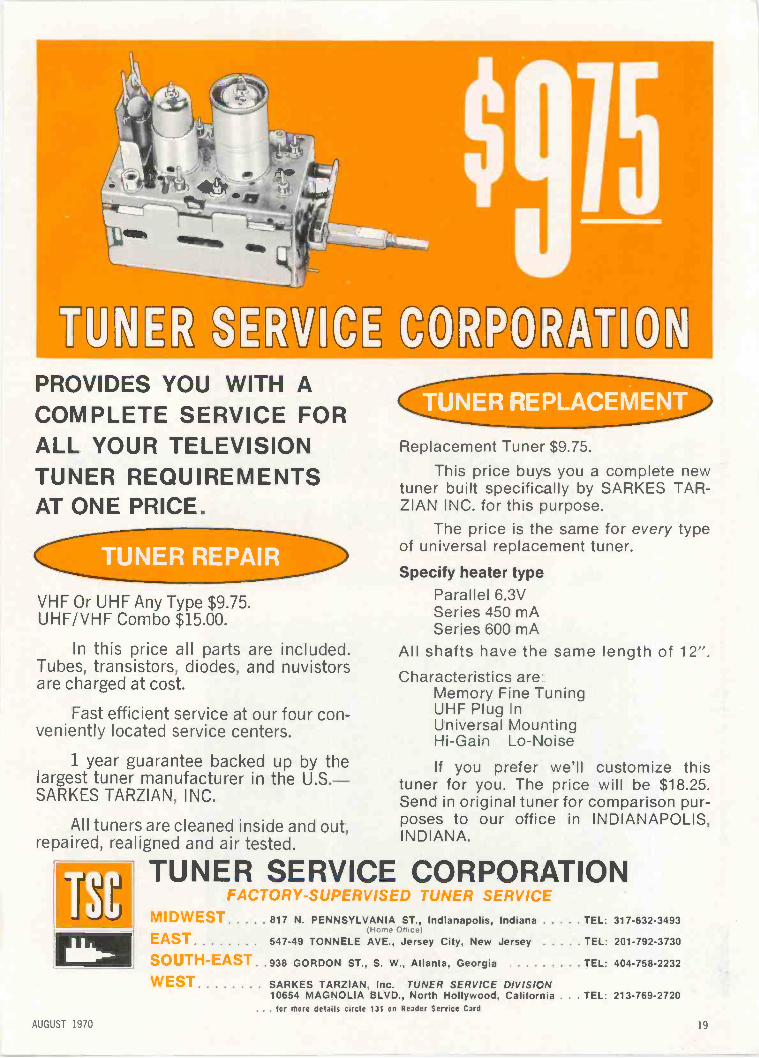
'UR eUP©ITPROVIDES YOU WITH ACOMPLETE SERVICE FORALL YOUR TELEVISIONTUNER REQUIREMENTSAT ONE PRICE,
VHF Or UHF Any Type $9.75.UHF/VI-IF Combo $15.00.
In this price all parts are included.Tubes, transistors, diodes, and nuvistorsare charged at cost.
Fast efficient service at our four con-veniently located service centers.
1 year guarantee backed up by thelargest tuner manufacturer in the U.S.-SARKES TARZIAN, INC.
All tuners are cleaned inside and out,repaired, realigned and air tested.
'11
Replacement Tuner $9.75.
This price buys you a complete newtuner built specifically by SARKES TAR-ZIAN INC. for this purpose.
The price is the same for every typeof universal replacement tuner.
Specify heater typeParallel 6.3VSeries 450 mASeries 600 mA
All shafts have the same length of 12".Characteristics are
Memory Fine TuningUHF Plug lnUniversal MountingHi -Gain Lo -Noise
If you prefer we'll customize thistuner for you. The price will be $18.25.Send in original tuner for comparison pur-poses to our office in INDIANAPOLIS,INDIANA.
TUNER SERVICE CORPORATIONFACT -SUPE,. ..)ED TUNER SERVICE
MIDWEST 817 N. PENNSYLVANIA ST., Indianapolis, Indiana TEL: 317-632-3493Home Office)
EAST 547-49 TONNELE AVE. Jersey City. New Jersey TEL: 201-792-3730
SOUTH-EAST. .938 GORDON ST.. S. W.. Atlanta. Georgia TEL: 404-758-2232
WEST SARKES TARZIAN. Inc. TUNER SERVICE DIVISICN10654 MAGNOLIA BLVD., North Hollywood. California . TEL: 213-769-2720
. for more details circle 131 on Reader Service Card
AUGUST 1970 19
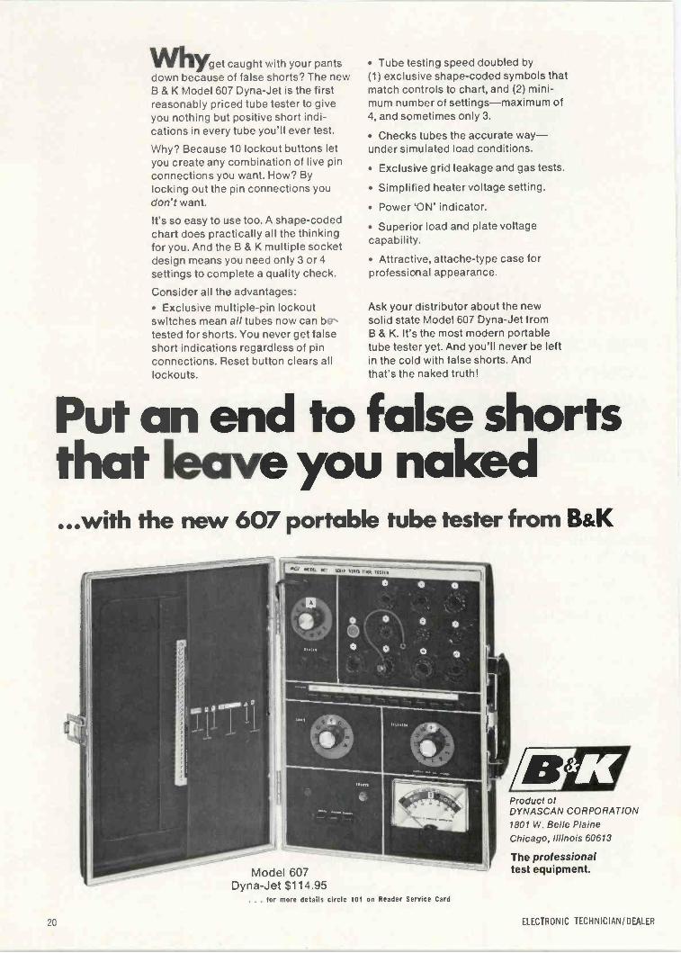
VVhyge, caught with your pantsdown because of false shorts? The newB & K Model 607 Dyna-Jet is the firstreasonably priced tube tester to giveyou nothing but positive short indi-cations in every tube you'll ever test.
Why? Because 10 lockout buttons letyou create any combination of live pinconnections you want. How? Bylocking out the pin connections youdon't want.
It's so easy to use too. A shape -codedchart does practically all the thinkingfor you. And the B & K multiple socketdesign means you need only 3 or 4settings to complete a quality check.
Consider all the advantages: Exclusive multiple -pin lockoutswitches mean all tubes now can betested for shorts. You never get falseshort indications regardless of pinconnections. Reset button clears alllockouts.
Tube testing speed doubled by(1) exclusive shape -coded symbols thatmatch controls to chart, and (2) mini-mum number of settings-maximum of4, and sometimes only 3.
Checks tubes the accurate way-under simulated load conditions.
Exclusive grid leakage and gas tests.
Simplified heater voltage setting.
Power 'ON' indicator.
Superior load and plate voltagecapability.
Attractive, attache -type case forprofessional appearance.
Ask your distributor about the newsolid state Model 607 Dyna-Jet fromB & K. It's the most modern portabletube tester yet. And you'll never be leftin the cold with false shorts. Andthat's the naked truth!
Put an end to false shortsthat leave you naked...with the new 607 portable tube tester from B&K
Model 607Dyna-Jet $114.95
... for more details circle 101 on Reader Service Card
Product of
DYNASCAN CORPORATION1801 W. Belle PlaineChicago, Illinois 60613
The professionaltest equipment.
ELECTRONIC TECHNICIAN/DEALER
HUGH "SCOTTY" WALLACEPublisherChicago:
(312) 467-0670
PHILLIP DAHLENEditor
Duluth:(218) 727-8511
JOSEPH ZAUHARManaging EditorEMILY WILSONAssociate Editor
DEBBIE GOLDBERGProduction EditorBOB ANDRESEN
Graphic DesignLILLIE PEARSON
Circulation FulfillmentJOHN KESSLER
Manager, Reader ServicesBERNICE GEISERT
Advertising Production
OFFICES
757 Third AvenueNew York, N.Y. 10017Phone: (212) 572-5000
Telex: 01-26286
43 East Ohio St.Chicago, III. 60611
Phone: (312) 467-0670Telex: 02-53549
1901 West 8th St.Los Angeles, Calif. 90057
Phone: (213) 483-8530
StreetDuluth, Minn. 55802
Phone: (218) 727-8511Telex: 02-94417
MANAGERS
HUGH "SCOTTY" WALLACEChicago: (312) 467-0670
DEAN GREENERChicago: (312) 467-0670
ALFRED A. MENEGUSNew York: (212) 572-4829
DONALD D. HOUSTONLos Angeles: (213) 483-8530
ROBERT UPTONTokyo, Japan
I.P.O., Box 5056
CHARLES S. HARRISON,CY JOBSON
San Francisco:(415) 392-6794
HARCOURT BRACE JOVANOVICH PUBLICATIONS
JOHN B. GELLATLYPresident
RICHARD MOELLERTreasurer
LARS FLADMARKSenior Vice -President
HARRY RAMALEYVice -PresidentTOM GRENEYVice -President
JAMES GHERNAArt Director
EDWARD CROWELLDirector of Marketing Services
37
40
48
51
ELECTRONICTECHNICIAN / DEALERWORLD'S LARGEST TV -RADIO SERVICE & SALES CIRCULATION
AUGUST 1970 VOLUME 92 NUMBER 2
INTRODUCING EMERSON'S MODEL 26C56 COLOR TV SETPart II-A review of this set's color circuits, plus a listing of production changes and sim-plified color control adjustments for faster troubleshooting techniques.
MASTER ANTENNA SYSTEMSThe basic principles of designing a satisfactory MATV system are described in detail in thisstaff written article.
FCC ALLOCATES CB EMERGENCY CHANNELIncrease sales and service by taking advantage of a field rapidly developing with growingpublic demand for emergency communications.
SERVICING SOLID-STATE STEREOPart Ill-This month's article deals with circuits designed to offer protection against line -voltage fluctuations.
53 HOW I STAYED IN THE TV BUSINESSRetired electronic technician maintains adequate income by rebuilding cathode ray tubes.
54 TESTLAB REPORTOur firsthand evaluation of Sencore's 13E156 dc bias supply and its 39G26 link detector-withstatistical data compiled from actual units.
22 EDITOR'S MEMO 64 NEWS OF THE INDUSTRY
24 LETTERS TO THE EDITOR 70 NEW PRODUCTS
30 TECHNICAL DIGEST 75 CATALOGS AND BULLETINS
32 COLORFAX 76 READER SERVICE INDEX
59 DEALER SHOWCASE
COVERElizabeth Hawkes Hall, located on the Superior campus of Wisconsin State University, containsan unusual MATV amplification -distribution system. The Blonder -Tongue system not only pro-vides individual channel amplification for all receivers in this dormitory, but also carriescombined signals through a cable to Frank A. Ross Hall, the men's dormitory, for additionalamplification and distribution.
TEKFAX 16 PAGES OF THE LATEST SCHEMATICS Group 216
AIRLINE: Color TV Model GEN-12440CEMERSON: Color TV Chassis 120976, 977, 980, 981, 982, 983, 984MAGNMIOX: TV Chassis T928 SeriesRCA VICTOR: Color TV Chassis CTC41 SeriesRCA VICTOR: TV Chassis KCS184A
IHIJI A HARCOURT BRACE JOVANOVICH PUBLICATION iir0
ELECTRONIC TECHNICIAN/ DEALER is published monthly by Harbrace Pub-lications, Inc., a subsidiary of Harcourt Brace Jovanovich Publications, Inc.Corporate Offices: 757 Third Avenue, New York, New York 100.7. AdvertisingOffices: 43 East Ohio Street, Chicago, Illinois 60611 and 757 Third Avenue, NewYork, New York 10017. Editorial, Accounting and Circulation Offices: 1 East FirstStreet, Duluth, Minnesota 55802. Subscription rates: One year $5, two years$8, three years $10, in the United States and Canada. Other countries: one year$9, two years $14, three years $18. Single copies: 75C in the U.S. and Canada;all other countries $2. Second class postage paid at Dansville, New York 14437and at additional mailing offices. Copyright 1970 by Harbrace Publications, Inc.POSTMASTER: Send form 3579 to ELECTRONIC TECHNICIAN/ DEALER,1 East First Street, Duluth, Minnesota 55802.
AUGUST 1970 21
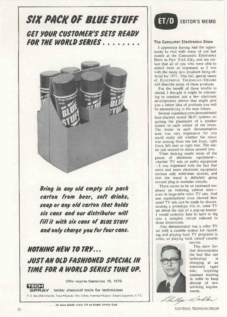
SIX Mae OF BLUE STUFF
GET YOUR CUSTOMER'S SETS READYFOR THE WORLD SERIES .....
Bring in any old empty six packcarton from beer, soft drinks,soap or any o/d carton that holdssix cans and our distributor willfill it with six cans of BLUE STUFF
and only charge you for four cans.
NOnmic NEW TO TRY...JUST AN OLD FASHIONED SPEC/AL IN
TIME FOR 4 WORLD SERIES TUNE UP.
TECHSPRAY
Offer expires September 15, 1970.
better chemical tools for techniciansP. O. Box 949 Amarillo, Texas Canada: Wm. Cohen, Montreal Export: Empire Exporters, N.Y.C.
. for more details circle 130 on Reader Service Card
EDITOR'S MEMO
The Consumer Electronics ShowI appreciate having had the oppor-
tunity to visit with many of you lastmonth at the Consumers ElectronicsShow in New York City, and am cer-tain that all of you who were able toattend were as impressed as I waswith the many new products being of-fered for 1971. This fall, special issuesof ELECTRONIC TECHNICIAN/DEALERwill describe many of these products.
For the benefit of those unable toattend, I thought it might be interest-ing to mention just a few electronicdevelopments shown that might giveyou a better idea of products you willbe encountering in the near future.
Several manufacturers demonstratedfour -channel sound Hi-Fi systems re-quiring the placement of a speakersystem in each corner of the room.The music in each demonstrationarea was very impressive for youcould easily tell whether the musicwas coming from the left front, rightfront, left rear or right rear. The mu-sic just seemed to dance around you.
When looking inside many of thepieces of electronic equipment-whether TV sets or audio equipment-I was impressed with the fact thatmore and more electronic equipmentcontain only solid-state circuits, andthat the trend is definitely goingtoward plug-in modular circuits.
There seems to be an increased em-phasis on reducing cabinet sizes-even in large -tube color TV sets. Andone manufacturer even showed howsmall TV sets can be made by demon-strating a prototype 41/2 -in. color TVset about the size of a pop-up toaster.I would certainly hate to have to diginto a complex circuit reduced tothose dimensions.
Also demonstrated was a color TVset with a cassette system for record-ing and playing back TV programs incolor, or playing back rented cassette
movies.This show fur-
ther demonstratesthe fact that ourtechnology ischanging at anextremely rapidrate, requiringconstant trainingin order to keepabreast of newservicing require-ments.
ELECTRONIC TECHNICIAN/DEALER
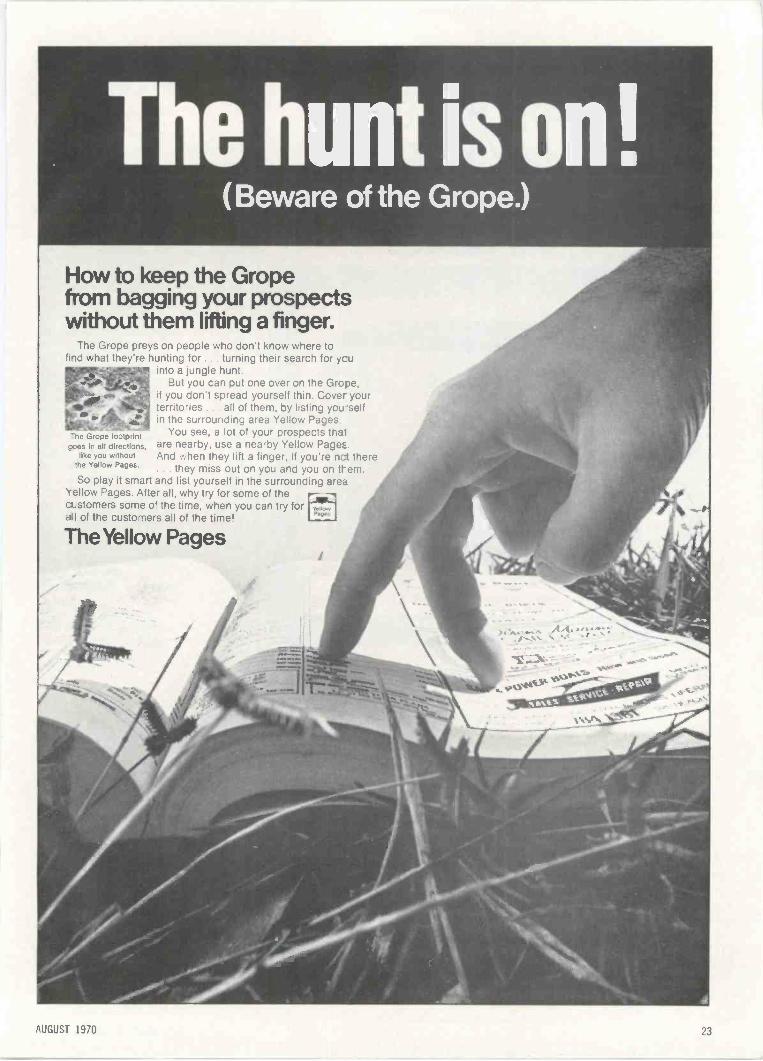
How to keep the Gropefrom bagging your prospectswithout them lifting a finger.
The Grope preys on people who don't know where tofind what they're hunting for .. turning their search for ycu
into a jungle hunt.But you can put one over on the Grope,
if you don't spread yourself thin. Cover yourterritories . . all of them, by listing you selfin the surrounding area Yellow Pages.
he Grope footprint You see, a lot of your prospects tf-at'goes in all directions, are nearby, use a nearby Yellow Page:.
like you without And when they lift a finger, if you're nct therethe Yellow Pages.
. . they miss out on you and you on them.So play it smart and list yourself in the surrounding area
Yellow Pages. After all, why try for some of thecustomers some of the time, when you can try for41 of the customers all of the time!
The Yellow Pages
AUGUST 1970
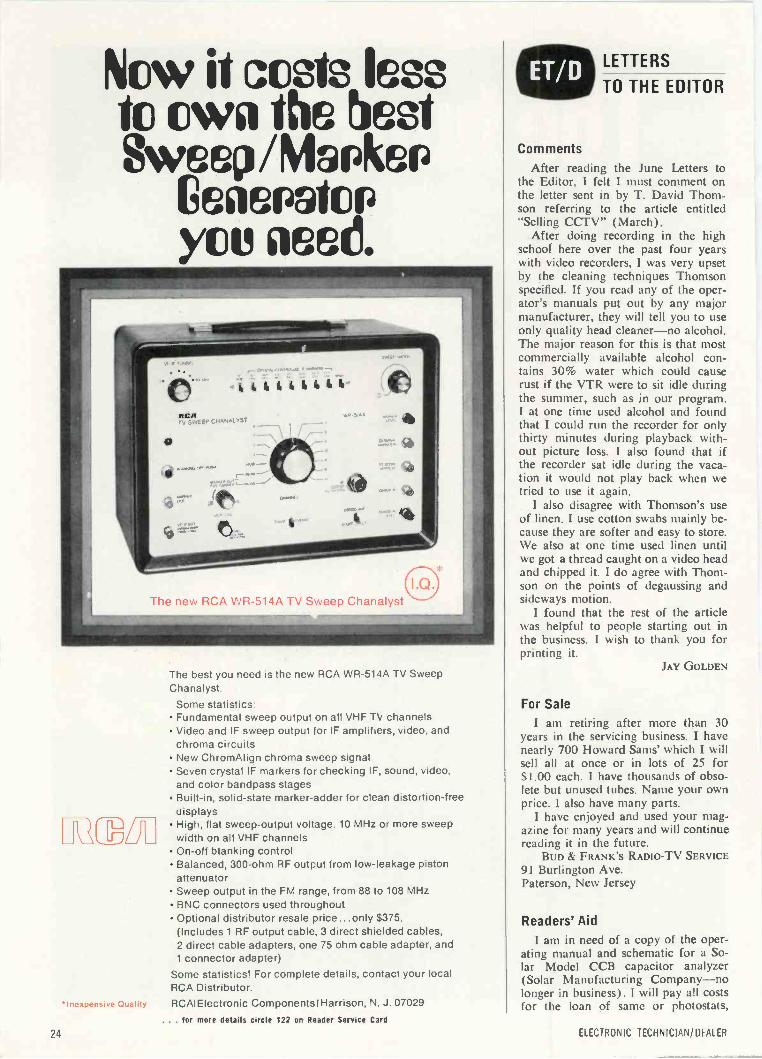
Now it costs lessto own the beatSww/Mapkep
GeasPatCPyou need.
I.Q.The new RCA WR-514A TV Sweep Chanalyst
MEM
'Inexpensive Quality
The best you need is the new RCA WR-514A TV SweepChanalyst.
Some statistics: Fundamental sweep output on all VHF TN, channels Video and IF sweep output for IF amplifiers, video. and
chroma circuits New ChromAlign chroma sweep signal Seven crystal IF markers for checking IF, sound, video,
and color bandpass stages Built-in, solid-state marker -adder for clean distortion -free
displays High, flat sweep -output voltage. 10 MHz or more sweep
width on all VHF channels On -off blanking control Balanced, 300 -ohm RF output from low -leakage piston
attenuator Sweep output in the FM range, from 88 to 108 MHz BNC connectors used throughout Optional distributor resale price... only $375.
(Includes 1 RF output cable, 3 direct shielded cables,2 direct cable adapters, one 75 ohm cable adapter, and1 connector adapter)
Some statistics! For complete details, contact your localRCA Distributor.RCAIElectronic Components I Harrison, N. J. 07029
... for more details circle 122 on Reader Service Card
LETTERS
TO THE EDITOR
CommentsAfter reading the June Letters to
the Editor, I felt I must comment onthe letter sent in by T. David Thom-son referring to the article entitled"Selling CCTV" (March).
After doing recording in the highschool here over the past four yearswith video recorders, I was very upsetby the cleaning techniques Thomsonspecified. If you read any of the oper-ator's manuals put out by any majormanufacturer, they will tell you to useonly quality head cleaner-no alcohol.The major reason for this is that mostcommercially available alcohol con-tains 30% water which could causerust if the VTR were to sit idle duringthe summer, such as in our program.I at one time used alcohol and foundthat I could run the recorder for onlythirty minutes during playback with-out picture loss. I also found that ifthe recorder sat idle during the vaca-tion it would not play back when wetried to use it again.
I also disagree with Thomson's useof linen. I use cotton swabs mainly be-cause they are softer and easy to store.We also at one time used linen untilwe got a thread caught on a video headand chipped it. I do agree with Thom-son on the points of degaussing andsideways motion.
I found that the rest of the articlewas helpful to people starting out inthe business. I wish to thank you forprinting it.
JAY GOLDEN
For SaleI am retiring after more than 30
years in the servicing business. I havenearly 700 Howard Sams' which I willsell all at once or in lots of 25 for$1.00 each. I have thousands of obso-lete but unused tubes. Name your ownprice. I also have many parts.
I have enjoyed and used your mag-azine for many years and will continuereading it in the future.
BUD & FRANK'S RADIO -TV SERVICE91 Burlington Ave.Paterson, New Jersey
Readers' Aid1 am in need of a copy of the oper-
ating manual and schematic for a So-lar Model CCB capacitor analyzer(Solar Manufacturing Company-nolonger in business). I will pay all costsfor the loan of same or photostats,
24 ELECTRONIC TECHNICIAN/DEALER
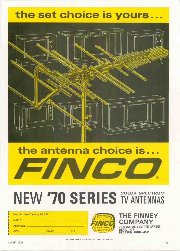
the set choice is yours...
the antenna choice is...
N EW '70 SERIES iiANTENNASr -
Send for free Catalog 20-556
NAME
ADDRESS
CITY STATE ZIP
4p,Of THE wORLD F
COLON
F/NC7:2)
THE FINNEYCOMPANY34 WEST INTERSTATE STREETDEPT. 110-8BEDFORD, OHIO 44146
AUGUST 1970
. for more detai s circle 109 on Reader Service Card
25
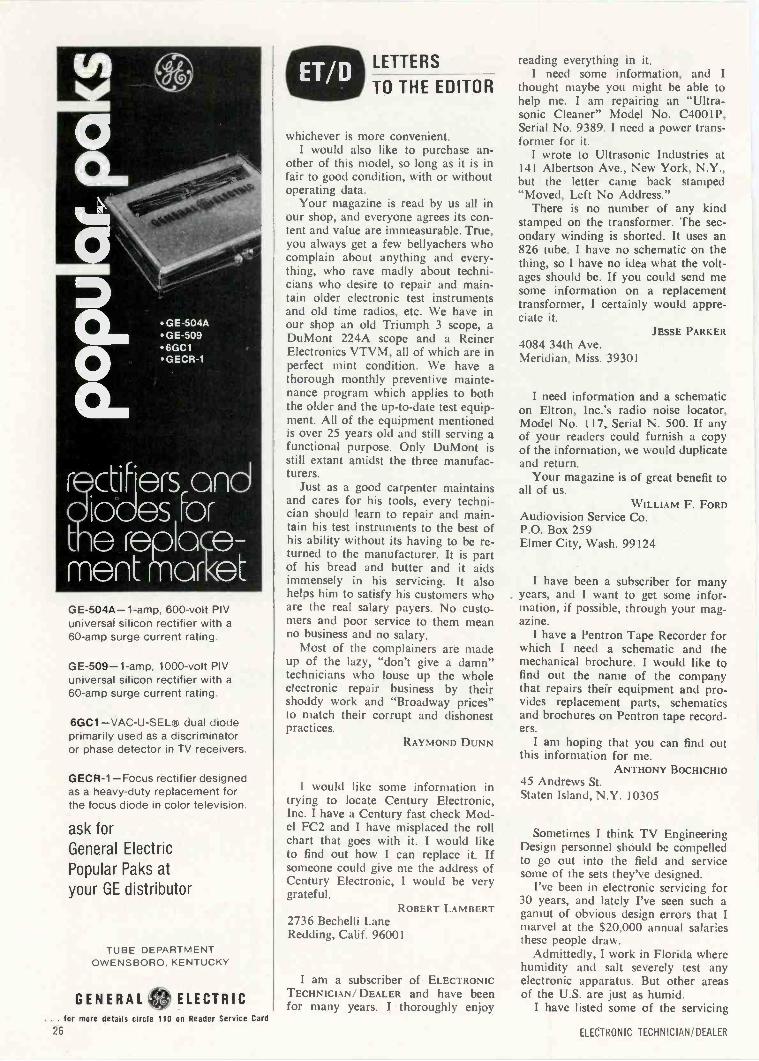
GE -504A- 1 -amp, 600 -volt PIVuniversal silicon rectifier with a60 -amp surge current rating
GE -509 -1 -amp, 1000 -volt PIVuniversal silicon rectifier with a60 -amp surge current rating.
6GC1 -VAC-U-SEL R dual diodeprimarily used as a discriminatoror phase detector in TV receivers.
GECR-1 -Focus rectifier designedas a heavy-duty replacement forthe focus diode in color television.
ask forGeneral ElectricPopular Paks atyour GE distributor
TUBE DEPARTMENTOWENSBORO. KENTUCKY
GENERAL ELECTRIC... for more details circle 110 on Reader Service Card
LETTERS
TO THE EDITOR
whichever is more convenient.I would also like to purchase an-
other of this model, so long as it is infair to good condition, with or withoutoperating data.
Your magazine is read by us all inour shop, and everyone agrees its con-tent and value are immeasurable. True,you always get a few bellyachers whocomplain about anything and every-thing, who rave madly about techni-cians who desire to repair and main-tain older electronic test instrumentsand old time radios, etc. We have inour shop an old Triumph 3 scope, aDuMont 224A scope and a ReinerElectronics VTVM, all of which are inperfect mint condition. We have athorough monthly preventive mainte-nance program which applies to boththe older and the up-to-date test equip-ment. All of the equipment mentionedis over 25 years old and still serving afunctional purpose. Only DuMont isstill extant amidst the three manufac-turers.
Just as a good carpenter maintainsand cares for his tools, every techni-cian should learn to repair and main-tain his test instruments to the best ofhis ability without its having to be re-turned to the manufacturer. It is partof his bread and butter and it aidsimmensely in his servicing. It alsohelps him to satisfy his customers whoare the real salary payers. No custo-mers and poor service to them meanno business and no salary.
Most of the complainers are madeup of the lazy, "don't give a damn"technicians who louse up the wholeelectronic repair business by theirshoddy work and "Broadway prices"to match their corrupt and dishonestpractices.
RAYMOND DUNN
I would like some information intrying to locate Century Electronic,Inc. I have a Century fast check Mod-el FC2 and I have misplaced the rollchart that goes with it. I would liketo find out how I can replace it. Ifsomeone could give me the address ofCentury Electronic, I would be verygrateful.
ROBERT LAMBERT2736 Bechelli LaneRedding, Calif. 96001
I am a subscriber of ELECTRONICTECHNICIAN/ DEALER and have beenfor many years. I thoroughly enjoy
reading everything in it.I need some information, and I
thought maybe you might be able tohelp me. I am repairing an "Ultra-sonic Cleaner" Model No. C4001P,Serial No. 9389. I need a power trans-former for it.
I wrote to Ultrasonic Industries at141 Albertson Ave., New York, N.Y.,but the letter came back stamped"Moved, Left No Address."
There is no number of any kindstamped on the transformer. The sec-ondary winding is shorted. It uses an826 tube. I have no schematic on thething, so I have no idea what the volt-ages should be. If you could send mesome information on a replacementtransformer, I certainly would appre-ciate it.
JESSE PARKER4084 34th Ave.Meridian, Miss. 39301
I need information and a schematicon Eltron, Inc.'s radio noise locator,Model No. 117, Serial N. 500. If anyof your readers could furnish a copyof the information, we would duplicateand return.
Your magazine is of great benefit toall of us.
WILLIAM F. FORDAudiovision Service Co.P.O. Box 259Elmer City, Wash. 99124
I have been a subscriber for manyyears, and I want to get some infor-mation, if possible, through your mag-azine.
I have a Pentron Tape Recorder forwhich I need a schematic and themechanical brochure. I would like tofind out the name of the companythat repairs their equipment and pro-vides replacement parts, schematicsand brochures on Pentron tape record-ers.
I am hoping that you can find outthis information for me.
ANTHONY BOCHICHIO45 Andrews St.Staten Island, N.Y. 10305
Sometimes I think TV EngineeringDesign personnel should be compelledto go out into the field and servicesome of the sets they've designed.
I've been in electronic servicing for30 years, and lately I've seen such agamut of obvious design errors that Imarvel at the $20,000 annual salariesthese people draw.
Admittedly, I work in Florida wherehumidity and salt severely test anyelectronic apparatus. But other areasof the U.S. are just as humid.
I have listed some of the servicing
26 ELECTRONIC TECHNICIAN/ DEALER
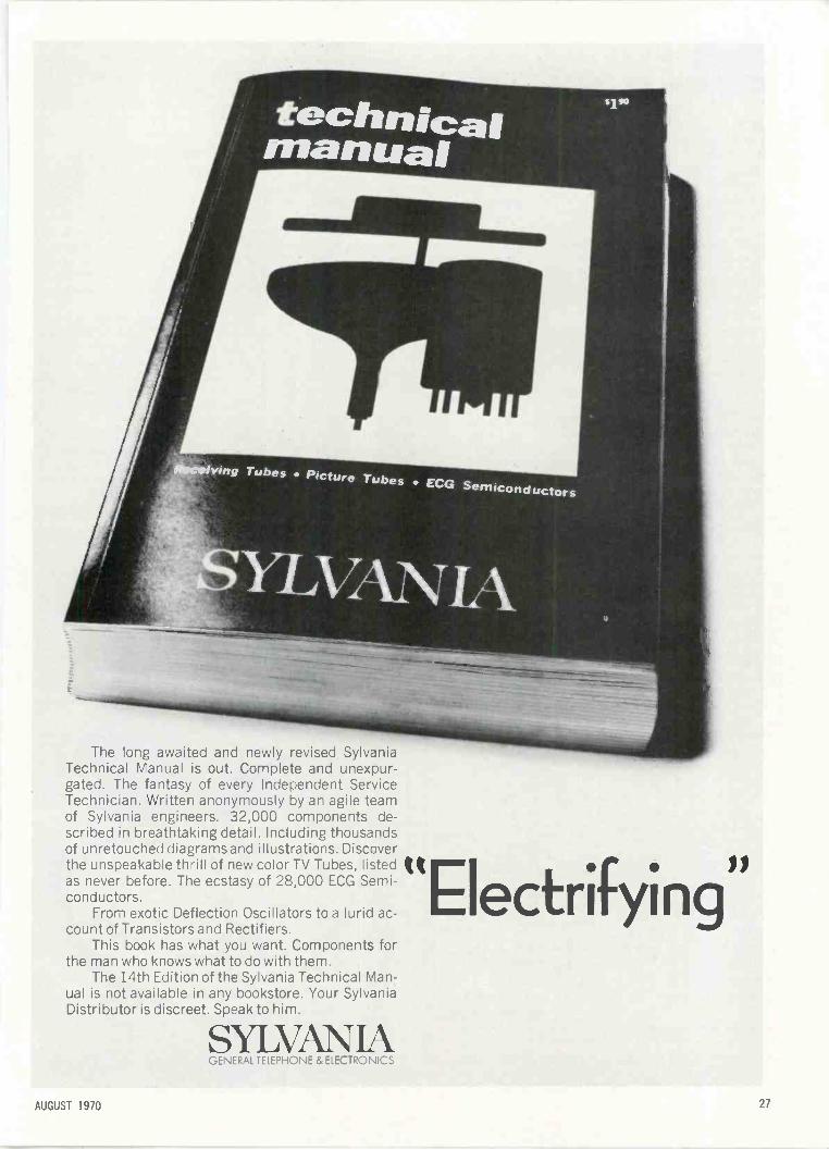
The long awaited and newly revised SylvaniaTechnical Manual is out. Complete and unexpur-gated. The fantasy of every Independent ServiceTechnician. Written anonymously by an agile teamof Sylvania engineers. 32,000 components de-scribed in breathtaking detail. Including thousandsof unretouched diagrams and illustrations. Discoverthe unspeakable thrill of new color TV Tubes, listedas never before. The ecstasy of 28,000 ECG Semi-conductors.
From exotic Deflection Oscillators to a lurid ac-count of Transistors and Rectifiers.
This book has what you want. Components forthe man who knows what to do with them.
The 14th Edition of the Sylvania Technical Man-ual is not available in any bookstore. Your SylvaniaDistributor is discreet. Speak to him.
SYLVANIAGENERAL TELEPHONE & ELECTRONICS
"Electrifyingif
AUGUST 1970
LETTERS
TO THE EDITOR
nightmares I've recently encounteredin color sets: Sharp bent wire -type anode con-
nectors-corona radiation eats upthe rubber insulation in six months.
Purity rings which literally rust to-gether in less than a year and re-quire disassembly to pry them apart.
Unyielding adhesives applied toyoke and picture tube surfaceswhich require (shudder) pressureon the picture tube bell to pry themloose.
Printed boards where high verticaloutput pulses are isolated fromground by a scant Vs in. of ques-tionable insulation.
Backs of sets which require threeseparate tools to remove.
Powdered iron slugs which freezeso tightly in the coils that adjust-ment without damage is impossible.One hotel here bought 10 color sets
and, early in the second year, had100% flyback failure.
Set manufacturers-is anyone listen-ing?
ROBERT M. SICKELS
I am in desperate need of a book onthe Analab 1100R dual trace scope. Ifnothing else is available, just the sche-matics will do.
FRANK PANKOMIN22487 BertieEdgemont, Calif. 92518
After 10 years of TV service, I amexpanding into mobile radio service.
Could you supply me with a list ofsources for service literature andschematics similar to Howard W.Sams' publications for TV.
I read your magazine regularly andfind it very informative and educa-tional.
AHRENDS ELECTRONICS21 Poplar St.Bloomingdale, N.J. 07403
Error in ArticleOn page 60 of the May 1970 issue
Of ELECTRONIC TECHNICIAN/DEALER,it states "50 times .000208 or .0104sec (104 msec)."
I believe that it should read 10.4msec.
In view of the large number of ar-ticles on math for technicians, it is ob-vious that accuracy is a must. Tech-
ANOTHER i eStREVOLUTIONARY from ,Ffie)i
SOUTH RIVER
GOLD VINYL COATED STEELANTENNA MOUNTSWITH 100% STAINLESS STEEL BANDING & HARDWARE
sNOW
Heavy duty steel riveted. Willnot peel, chip or crack due to badweather or exposure to the rays ofthe sun. Will not corrode; elimi-nates rust streaks.
THE FIRST VINYL COATEDTV ANTENNA MOUNTS
GUARANTEEDNOT TO RUSTFOR 25 YEARSOR WE WILL REPLACETHEM FREE OF CHARGE
SEND FOR DATA SHEET
{. BOLT MAST SOCKET
TWO TO A SET
GOLD VINYLCOATEDCHIMNEY MOUNT
MODEL V -DM -ST - 12 ft. S.S. STRAPSMODEL V -DM -ST -XL - 18 ft. S.S. STRAPS
ALSO AVAILABLE IN SNAP -INCHIMNEY MOUNT MODELS
ALL HARDWARE 100% STAINLESS STEEL
GOLD VINYL COATED6" SNAP -IN TYPEWALL BRACKETsrAmass
STEEL SCREWS
Air SUPPLIED
TWO TOA SET
MODEL V-SN-6
ALSO AVAILABLE IN 4"SNAP -IN & 6" "V" TYPEWALL BRACKET MODELS
SELL & INSTALL SOUTH RIVER GOLD VINYL COATED MOUNTSFOR THE FINEST INSTALLATIONS
SOUTH RIVER METAL PRODUCTS CO., INC.SOUTH RIVER, NEW JERSEY 08882 12011 254-5252
nicians must be sticklers for details ifthey expect to master the complexmonsters that they are supposed toservice properly.
ARTHUR A. GAGE
Thanks Given for HelpI would like to thank you for your
return letter to my letter of May 19,1970. (We provided him with the nameof a manufacturer of a product he re-membered seeing sometime back inELECTRONIC TECHNICIAN/ DEALER. )I'm sure the problem which I posedwas not an easy one for you to solve.I'm sure it took a lot of time and trou-ble on your part.
I'm sure I can well understand thepride taken in their work by the peo-ple who are employed by ELECTRONICTECHNICIAN/DEALER when one suchas you takes so much time and trou-ble to assist a subscriber, especially un-der the circumstances that were in-volved in this request.
Again, thank you and, if you will,submit this letter of appreciation toyour superior to let him know of theexcellent job you are doing for ELEC-TRONIC TECHNICIAN/DEALER.
Thanking you again for your coop-eration in this matter.
JOHN WILLIAM WEIDOWKE
GaRM COAXLINE SPLITTER
For UHF VHFColor B&W TV
The Mosley M-22\two set, and M-24 four set75 ohm coax splitters for color TV/FMStereo distribution systems. High inter -
set isolation, low insertion loss.Models may be combined to provide
any number of lines for largeramplified systems.
Solderless. Easyinstallation.
" Write Dept. 159A for FREE detailed brochure.
Mr"I" egc/zerufft Sza 4a6,!dOgeN,..nLi di .b:or rh B6 31 vod4.
for more details circle 129 on Reader Service Card . for more details circle 118 on Reader Service Card
ELECTRONIC TECHNICIAN/DEALER
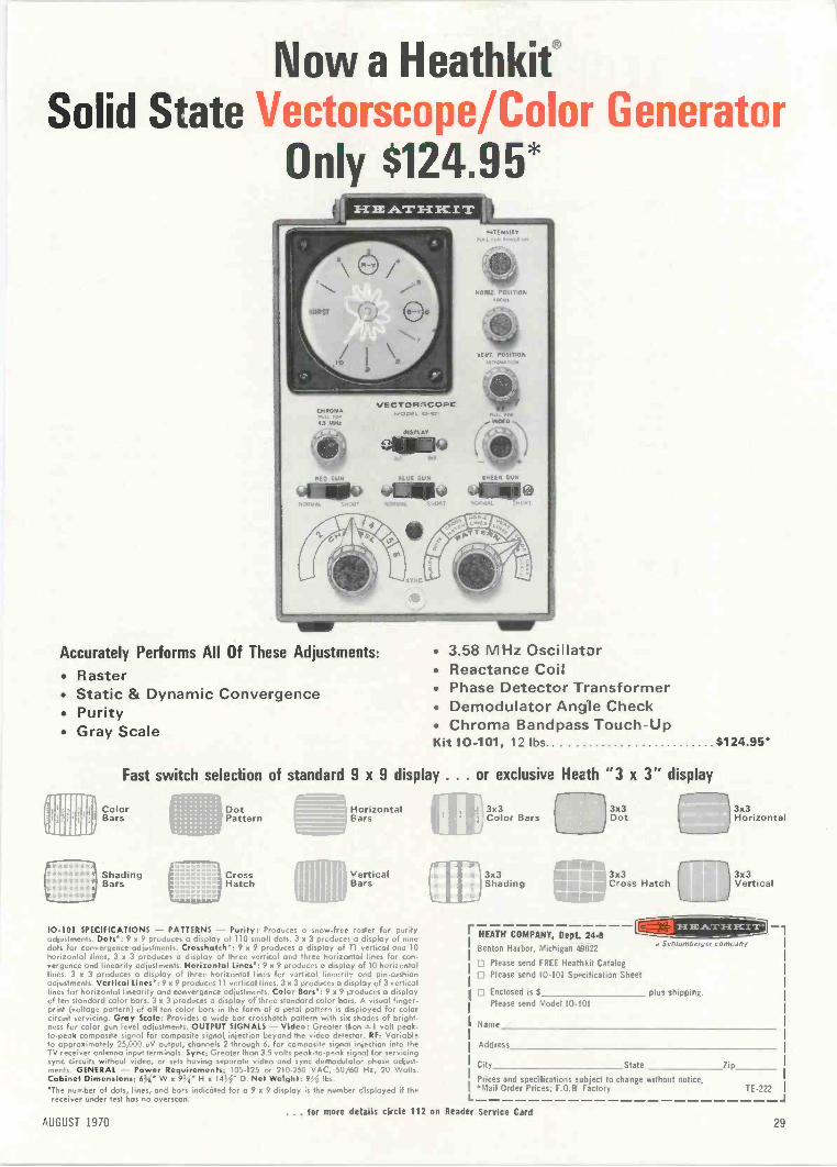
Now a HeathkitSolid State Vectorscope/Color Generator
Only $124.95*
RED GUN SLUE GUN
441111100 61111.0
Accurately Performs All Of These Adjustments:
RasterStatic & Dynamic ConvergencePurity
Gray Scale
3.58 MHz OscillatorReactance Coil
Phase Detector Transformer Demodulator Angle Check Chroma Bandpass Touch -UpKit 10-101, 12 lbs. $124.95'
Fast switch selection of standard 9 x 9 display . . . or exclusive Heath "3 x 3" display
ColorBars
ShadingBars
1 DotPatter 11
rCrossHatch
HorizontalEars
) VerticalBars
10-101 SPECIFICATIONS - PATTERNS - Purity: Produces a snow -free raster for purityadjustments. Dots': 9 a 9 produces a display of 110 small dots. 3 a 3 produces a display of ninedots for convergence adjustments. Crosshatch': 9 x 9 produces a display of Ti vertical and 10horizontal lines. 3 x 3 produces a display of three vertical and three horizontal lines for con-vergence and linearity adjustments. Horizontal Lines*: 9 x 9 produces a display of 10 horizontallines. 3 x 3 produces a display of three horizontal lines for vertical linearity a-sd pin -cushionadjustments. Vortical Lines': 9 a 9 produces 11 vertical lines. 3 a 3 produces a display of 3 verticallines for horizontal linearity and convergence adjustments. Color Bars': 9 x 9 produces a displayof ten standard color bars. 3 a 3 produces a display of three standard color bars. A visual finger-print (voltage pattern) of all ten color bars in the form of a petal pattern is d splayed for colorcircuit servicing. Gray Scale: Provides a wide bar crosshatch pattern with six shades of bright-ness for color gun level adjustments. OUTPUT SIGNALS - Video: Greater lion tl volt peak -to -peak composite signal for composite signal, injection beyond the video detector. RF: Variableto approximately 25.000 uV output, channels 2 through 6, for composite signal injection into theTV receiver antenna input terminals. Sync: Greater than 3.5 volts peak -to -peak signal for servicingsync circuits without video, or sets having separate video and sync demodulator phase adjust-ments. GENERAL - Power Requirements: 105.125 or 210-250 VAC, 50/60 Hz, 20 Watts.Cabinet Dimensions: 634' W x 914' H x 14,1' D. Net Weight: 9, lbs.
'The number of dots, lines, and bars indicated for a 9 x 9 display is the number displayed if thereceiver under test hos no overscon.
r13x3
Color Bars
)3x3Shading
r -13 x 3Dot
J
r HEATH COMPANY, Dept. 24-8Benton Harbor, Michigan 49022
Please send FREE Heatnkit Catalog01 Please send 10-101 Specification Sheet
O Enclosed is 1 plus shipping.Please send Model 10-101
3x3Cross Hatch
r
3x3Horizontal
3x3Vertical
Name
11111111=10a Schlumbefger company
Address
City State Zip
Prices and specifications subject to change without notice.*Mail Order Prices; F.O.B. Factory 7E-222
. for more details circle 112 on Reader Service CardAUGUST 1970 29
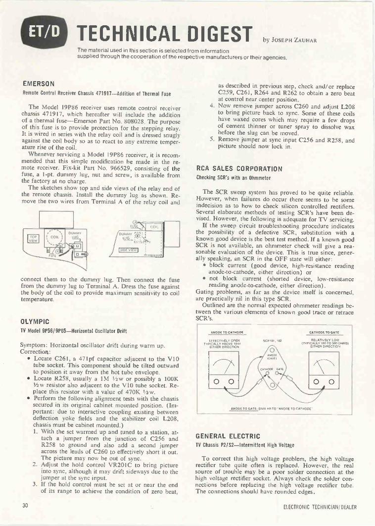
TECHNICAL DIGESTThe material used in this section is selected from informationsupplied through the cooperation of the respective manufacturers or their agencies.
EMERSON
Remote Control Receiver Chassis 471917-Addition of Thermal Fuse
The Model 19P86 receiver uses remote control receiverchassis 471917, which hereafter will include the additionof a thermal fuse-Emerson Part No. 808028. The purposeof this fuse is to provide protection for the stepping relay.It is wired in series with the relay coil and is dressed snuglyagainst the coil body so as to react to any extreme temper-ature rise of the coil.
Whenever servicing a Model 19P86 receiver, it is recom-mended that this simple modification be made in the re-mote receiver. Fix -kit Part No. 966529, consisting of thefuse, a 1 -pt. dummy lug, nut and screw, is available fromthe factory at no charge.
The sketches show top and side views of the relay end ofthe remote chassis. Install the dummy lug as shown. Re-move the two wires from Terminal A of the relay coil and
EVIL COIL
IDULMUMGY 0
!SIDE VIEW I
connect them to the dummy lug. Then connect the fusefrom the dummy lug to Terminal A. Dress the fuse againstthe body of the coil to provide maximum sensitivity to coiltemperature.
OLYMPIC
TV Model 9P56/9P65-Horizontal Oscillator Drift
Symptom: Horizontal oscillator drift during warm up.Correction:
Locate C261, a 471pf capacitor adjacent to the VIOtube socket. This component should be tilted outwardto position it away from the hot tube envelope.
Locate R258, usually a 1M 1/2w or possibly a 100K1/2w resistor also adjacent to the V10 tube socket. Re-place this resistor with a value of 470K 1/2w.
Perform the following alignment tests with the chassissecured in its original cabinet mounted position. (Im-portant: due to interactive coupling existing betweendeflection yoke fields and the stabilizer coil L208,chassis must be cabinet mounted.)1. With the set warmed up and tuned to a station, at-
tach a jumper from the junction of C256 andR258 to ground and also add a second jumperacross the leads of C260 to effectively short it out.The picture may now be out of sync.
2. Adjust the hold control VR201C to bring pictureinto sync, although it may drift sideways due to thejumper at the sync input.
3. If the hold control must be set at or near the endof its range to achieve the condition of zero beat,
as described in previous step, check and/or replaceC259, C26I, R264 and R262 to obtain a zero beatat control near center position.
4. Now remove jumper across C260 and adjust L208to bring picture back to sync. Some of these coilshave waxed cores which may require a few dropsof cement thinner or tuner spray to dissolve waxbefore the slug can be moved.
5. Remove jumper at sync input C256 and R258, andpicture should now lock in.
RCA SALES CORPORATIONChecking SCR's with an Ohmmeter
The SCR sweep system has proved to be quite reliable.However, when failures do occur there seems to be someindecision as to how to check silicon controlled rectifiers.Several elaborate methods of testing SCR's have been de-vised. However, the following is adequate for TV servicing.
If the sweep circuit troubleshooting procedure indicatesthe possibility of a defective SCR, substitution with aknown good device is the best test method. If a known goodSCR is not available, an ohmmeter check will give a rea-sonable evaluation of the device. This is true since, gener-ally speaking, an SCR in the OFF state will either:
block current (good device, high -resistance readinganode -to -cathode, either direction) or
not block current (shorted device, low -resistancereading anode -to -cathode, either direction).
Gating problems, as far as the device itself is concerned,are practically nil in this type SCR.
Outlined are the normal expected ohmmeter readings be-tween the various elements of known good trace or retraceSCR's.
ANODE TO CATHODE
EFFECTIVELY OPENTYPICALLY ABOVE IOM
EITHER DIRECTION
SCR101. 102
CATHODE TO GATE
RELATIVELY LOW(TYPICALLY 100 70 500 OHMS)
EITHER DIRECTION
ANODE TO GATE, SIMILAR TO "ANODE TO CATHODE
GENERAL ELECTRICTV Chassis P2/S2-Intermittent High Voltage
To correct this high voltage problem, the high voltagerectifier tube quite often is replaced. However, the realsource of trouble may be a poor solder connection at thehigh voltage rectifier socket. Always check the solder con-nections before replacing the high voltage rectifier tube.The connections should have rounded edges.
30 ELECTRONIC TECHNICIAN/DEALER
n
WHATYOU DOFOR ANENCORE...?after you have sold your customersthe best home TV towers.
That's one of the big advantages when you stock and sell SpauldingAX Series Home TV Towers. You're offering a tower in which they'llnot only see the quality, which is apparent, but they'll also see thetrouble -free performance they are looking for.
The Spaulding AX Home TV Tower is designed for quick economicalinstallation . . . and is all -steel, galvanized and all riveted constructionwith no welts to rust.
The AX 48' Home TV Tower package cnly requires 2 sq. ft. of floorspace . . . the AX series packages are available in heights up to 64'.Package includes base stubs, hardware, mast and mast kit.
The Spaulding AX Series Tcwer is a self-supporting tower andis extremely rigid under most erection situations. The highertie tower goes, Vie greater the strength at the base. The windresistance at the top decreases with height. The "tapering"effect adds to the attractiveness of the tower.
Get specifications on this complete tower package, and profitin two ways --bigger sales and greater goodwill from yourcustomers.
ROHM-SPAULDING, INC.Peoria, Illinois Birmingham, Alabama Frankfort, Indiana
AUGUST 1970... for more details circle 124 on Reader Service Card
31
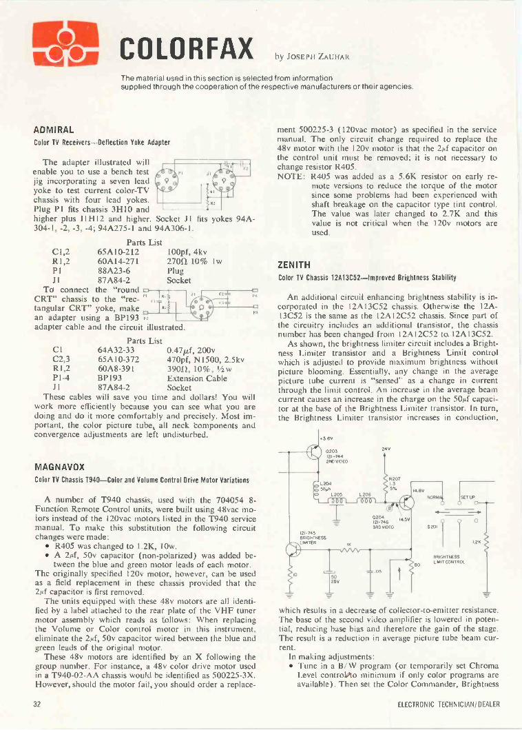
COLORFAX by Josi.i.ii ZAUHAR
The material used in this section is selected from informationsupplied through the cooperation of the respective manufacturers or their agencies.
ADMIRALColor TV Receivers-Deflection Yoke Adapter
The adapter illustrated willenable you to use a bench testjig incorporating a seven leadyoke to test current color -TVchassis with four lead yokes.Plug P1 fits chassis 3H10 andhigher plus I1H12 and higher. Socket .11 fits304-1, -2, -3, -4; 94A275-1 and 94A306-1.
Parts ListC1,2 65A10-212R1,2 60A14-271P1 88A23-6J1 87A84-2
To connect the "round
yokes
100pf, 4kv27012 10% 1 wPlugSocket
CRT" chassis to the "rec-tangular CRT" yoke, make 1"2
an adapter using a BP1930
adapter cable and the circuit illustrated.
Parts ListCI 64A32-33 0.47/Lf, 200vC2,3 65A10-372 470pf, N1500, 2.5kvR1,2 60A8-391 39011, 10%, 1/2wP1-4 BP193 Extension CableJ 1 87A84-2 Socket
These cables will save you time and dollars! You willwork more efficiently because you can see what you aredoing and do it more comfortably and precisely. Most im-portant, the color picture tube, all neck components andconvergence adjustments are left undisturbed.
94A -
,-L
MAGNAVOX
Color TV Chassis T940-Color and Volume Control Drive Motor Variations
P
P3
A number of T940 chassis, used with the 704054 8 -Function Remote Control units, were built using 48vac mo-tors instead of the 120vac motors listed in the T940 servicemanual. To make this substitution the following circuitchanges were made:
R405 was changed to 1.2K, lOw. A 24, 50v capacitor (non -polarized) was added be-
tween the blue and green motor leads of each motor.The originally specified 120v motor, however, can be usedas a field replacement in these chassis provided that the2µf capacitor is first removed.
The units equipped with these 48v motors are all identi-fied by a label attached to the rear plate of the VHF tunermotor assembly which reads as follows: When replacingthe Volume or Color control motor in this instrument,eliminate the 24, 50v capacitor wired between the blue andgreen leads of the original motor.
These 48v motors are identified by an X following thegroup number. For instance, a 48v color drive motor usedin a T940 -02 -AA chassis would be identified as 500225-3X.However, should the motor fail, you should order a replace-
ment 500225-3 (120vac motor) as specified in the servicemanual. The only circuit change required to replace the48v motor with the 120v motor is that the 2µf capacitor onthe control unit must be removed; it is not necessary tochange resistor R405.NOTE: R405 was added as a 5.6K resistor on early re-
mote versions to reduce the torque of the motorsince some problems had been experienced withshaft breakage on the capacitor type tint control.The value was later changed to 2.7K and thisvalue is not critical when the 120v motors areused.
ZENITH
Color TV Chassis 12A13C52-Improved Brightness Stability
An additional circuit enhancing brightness stability is in-corporated in the 12A13C52 chassis. Otherwise the 12A -13C52 is the same as the 12Al2C52 chassis. Since part ofthe circuitry includes an additional transistor, the chassisnumber has been changed from I 2A I 2C52 to 12A 13C52.
As shown, the brightness limiter circuit includes a Bright-ness Limiter transistor and a Brightness Limit controlwhich is adjusted to provide maximum brightness withoutpicture blooming. Essentially, any change in the averagepicture tube current is "sensed" as a change in currentthrough the limit control. An increase in the average beamcurrent causes an increase in the charge on the 50µf capaci-tor at the base of the Brightness Limiter transistor. In turn,the Brightness Limiter transistor increases in conduction,
0203121-7442NO VIDEO
L 204S8Uh
L 205 L 206
24V
SET UP
BRIGHTNESSLIMIT CONTROL
0
L2K
which results in a decrease of collector -to -emitter resistance.The base of the second video amplifier is lowered in poten-tial, reducing base bias and therefore the gain of the stage.The result is a reduction in average picture tube beam cur-rent.
In making adjustments: Tune in a B/W program (or temporarily set Chroma
Level controlOto minimum if only color programs areavailable). Then set the Color Commander, Brightness
32 ELECTRONIC TECHNICIAN/ DEALER
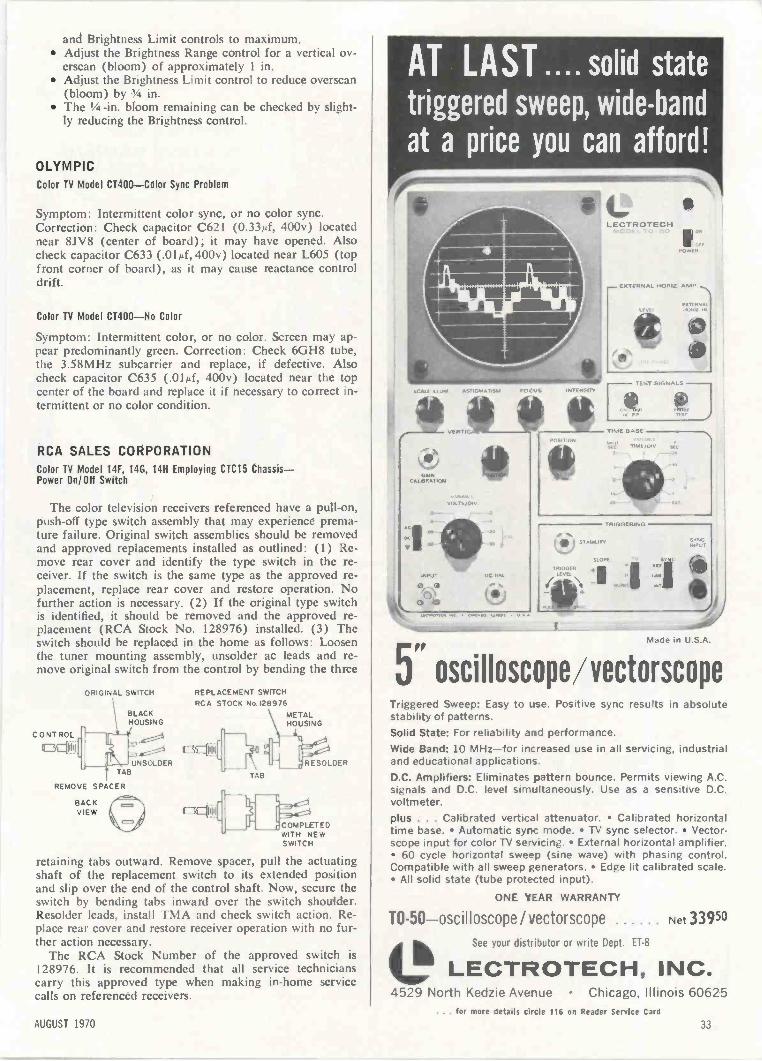
and Brightness Limit controls to maximum. Adjust the Brightness Range control for a vertical ov-
erscan (bloom) of approximately 1 in. Adjust the Brightness Limit control to reduce overscan
(bloom) by 34 in. The 1/4 -in. bloom remaining can be checked by slight-
ly reducing the Brightness control.
OLYMPICColor TV Model CT400-Color Sync Problem
Symptom: Intermittent color sync, or no color sync.Correction: Check capacitor C621 (0.33pf, 400v) locatednear 8JV8 (center of board); it may have opened. Alsocheck capacitor C633 (.01pf, 400v) located near L605 (topfront corner of board), as it may cause reactance controldrift.
Color TV Model CT400-No Color
Symptom: Intermittent color, or no color. Screen may ap-pear predominantly green. Correction: Check 6GH8 tube,the 3.58MHz subcarrier and replace, if defective. Alsocheck capacitor C635 (.014, 400v) located near the topcenter of the board and replace it if necessary to correct in-termittent or no color condition.
RCA SALES CORPORATIONColor TV Model 14F, 14G, 14H Employing CTC15 Chassis-Power On/Off Switch
The color television receivers referenced have a pull -on,push -off type switch assembly that may experience prema-ture failure. Original switch assemblies should be removedand approved replacements installed as outlined: (1) Re-move rear cover and identify the type switch in the re-ceiver. If the switch is the same type as the approved re-placement, replace rear cover and restore operation. Nofurther action is necessary. (2) If the original type switchis identified, it should be removed and the approved re-placement (RCA Stock No. 128976) installed. (3) Theswitch should be replaced in the home as follows: Loosenthe tuner mounting assembly, unsolder ac leads and re-move original switch from the control by bending the three
CONTROL
lE3C1ii
ORIGINAL SWITCH
BLACKHOUSING
REPLACEMENT SWITCHRCA STOCK No.128976
METALHOUSING
1111: COOUNSOLDER
TAB
REMOVE SPACER
SACKVIEW
TAB
RESOLDER
COMPLETEDWITH NEWSWITCH
retaining tabs outward. Remove spacer, pull the actuatingshaft of the replacement switch to its extended positionand slip over the end of the control shaft. Now, secure theswitch by bending tabs inward over the switch shoulder.Resolder leads, install TMA and check switch action. Re-place rear cover and restore receiver operation with no fur-ther action necessary.
The RCA Stock Number of the approved switch is128976. It is recommended that all service technicianscarry this approved type when making in -home servicecalls on referenced receivers.
AT LAST.... solid statetriggered sweep, wide -band
at a price you can afford!
ramoiwimm-irieriog II 1
SCALE ILIUM ASTIGMATISM FOCUS.
GAINCAL IIMA 1 ION
VEATIC
INTENSITY
POE, ION
SIAM 1 T I
TRIGGER
CLECTROTECH
S111 AN
CO,POINTS
- f I ANAL HORIZ AMP
TIME BASE
A IGGE ING
1
oscilloscope/vectorscopeTriggered Sweep: Easy to use. Positive sync results in absolutestability of patterns.Solid State: For reliability and performance.Wide Band: 10 MHz-for increased use in all servicing, industrialand educational applications.D.C. Amplifiers: Eliminates pattern bounce. Permits viewing A.C.signals and D.C. level simultaneously. Use as a sensitive D.C.voltmeter.plus . . . Calibrated vertical attenuator. Calibrated horizontaltime base. Automatic sync mode. TV sync selector. Vector -scope input for color TV servicing. External horizontal amplifier. 60 cycle horizontal sweep (sine wave) with phasing control.Compatible with all sweep generators. Edge lit calibrated scale. All solid state (tube protected input).
ONE YEAR WARRANTY
TO-50-oscilloscope / vectorscope Net 3 3950
See your distributor or write Dept. ET -8
LECTROTECH, INC.4529 North Kedzie Avenue Chicago, Illinois 60625
... for more details circle 116 on Reader Service Card
AUGUST 1970 33
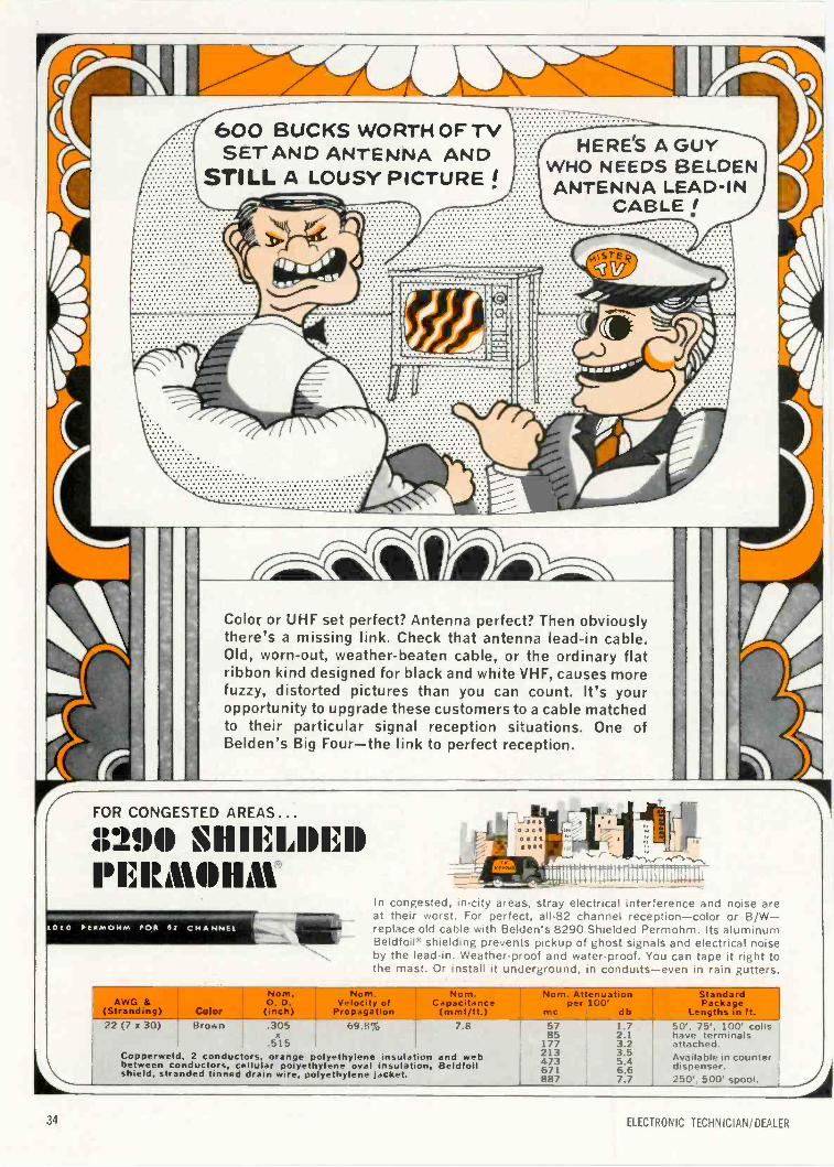
600 BUCKS WORTH OF TVSET AND ANTENNA AND
STILL A LOUSY PICTURE !HERE'S A GUY -Th
WHO NEEDS BELDENANTENNA LEAD-IN
CABLE!'.'.'..'.'.'.'
-'i; ---4NINIIi7-..-...'\-L.1 ii:Color or UHF set perfect? Antenna perfect? Then obviouslythere's a missing link. Check that antenna lead-in cable.Old, worn-out, weather-beaten cable, or the ordinary flatribbon kind designed for black and white VHF, causes morefuzzy, distorted pictures than you can count. It's youropportunity to upgrade these customers to a cable matchedto their particular signal reception situations. One ofBelden's Big Four-the link to perfect reception.
FOR CONGESTED AREAS ...
8290 SHIELDEDPFRMOHAt
L1210 PtPMOHM POE 82 CHANNEL
L
In congested, in -city areas, stray electrical interference and noise areat their worst. For perfect, all -82 channel reception-color or B/W-replace old cable with Belden's 8290 Shielded Permohm. Its aluminumBeldfoil® shielding prevents pickup of ghost signals and electrical noiseby the lead-in. Weather-proof and water -proof. You can tape it right tothe mast. Or install it underground, in conduits-even in rain gutters.
Nom. Nom. Nom.MVO & O. D. Velocity of Capacitanc.
(Stranding) Color (inch) Propagation (mmf/ft.)22 (7 x 30) Brown .305 fxq.237,:,
.515Copperweld, 2 conductors, orange polyethylene insulation and webbetween conductors, cellular polyethylene oval insulation, Beldfoilshield, stranded tinned drain wire, polyethylene jacket.
ErNom. Attenuationper 100
me db
17/213473671887
2.l3.23.55.46.67.7
Lengths in ft.
StandardPackage
L
50'. 75', 100 coilshave terminalsattached.Available in counterdispenser.250'. 500' spool.
34 ELECTRONIC TECHNICIAN/DEALER
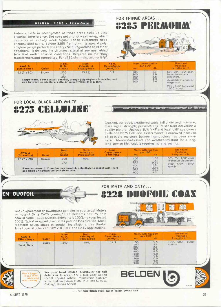
P"'7 - FOR FRINGE AREAS...
BELDEN 8285 - PERNIOHM1121;i 1°Iiitt1111/H111
Antenna cable in uncongested or fringe areas picks up littleelectrical interference. But does get a lot of weathering, whichdegrades an already weak signal. These customers need '
encapsulated cable. Belden 8285 Permohm. Its special poly- 7--D,..-
ethylene jacket protects the energy field, regardless of weather _
conditions. It delivers the strongest signal of any unshieldedtwin lead under adverse conditions. Requires no matching -transformers and connectors. For all 82 channels, color or B/W. vno
---. /
t..,
'
..4 I
'a
LI
' '''', ......., -,.-7-'1
AW &trending)
Velocity of -Capacitance per 100'Color (inch.) Propagation (mmf/ft.) me db
arilPackage
Lengths in ft.
22 (7 x 30)
Copperweld,web between
Brown .255 5.3x
4682 conductors parallel, orange polyethylene insulation andconductors, cellular polyethylene oval jacket.
i 1
100 1.4300 2.8500 3.8700 4.8900 5.6
50', 75', 100' coilshave terminalsattached.Available in counterdispenser.250' 500' coils andIwo' spool.
FOR LOCAL BLACK AND WHITE...lb 9gill.. I.)
' - ---- Z ---,...........4,...
AI%A
`-1ar
17 1li
-Ea.,
\
IAIAIP
' ----L:
N-....,,
1 II INAI
--
1 WM
,
11I i1..IA
Cracked, corroded, weathered cable, full of dirt and moisture,loses signal strength; prevents any TV set from delivering aquality picture. Upgrade B/W VHF and local UHF customersto Belden 8275 Celluline. Performance is improved becauseall possible moisture between conductors has been elimi-nated. Abrasion -resistant and weather -resistant for a long,long service life. And, it requires no end sealing.
-
m. Attenuation - Standard _
pee 100' Packs
20 (7 x 28)
Bare copperweld;gas filled unicellular
Brown
2 conductorspolyethylene
.300 80%x
.400
parallel, polyethylene jacketcore.
4.6 100 1.05 50', 75', 100' coils200 1.64 in counter dispenser.300 2.12400 2.5 250', 500', 1000'
with inert 500 2.98 spools.700 3.62900 4.3
EN DUOFOIL _-1FOR MATV AND
II 2211
CATV...
II 1101701.....
1, I: 11111 Xr"----'. -- --rAm
Got an apartment or townhouse complex in your area? Motels VG,______
or hotels? Or is CATV coming? Use Belden's new 75 ohm f--,-.7.1* L. -a,- , c.. " -,,,
coaxial cable -8228 Duofoil. Shielding is 100% -sweep tested Ott.A 1 2 'OR' -1-
100%. Spiral wrapped drain wires provide long flex life. Small SEP .1 if t * Iiiiik, )1
diameter saves space in conduit installations. Use Duofoil-''.00 -
Rte ,b 'I I. 11-ft.-
tri4,.:,-,
,- jiI. - li.._,-..t.=_:.
_
4 e.--
for all coaxial color and B/W VHF, UHF and CATV applications. %V
18Solid, Bare
Black .242 78% 17.3 50100200300400500600700800900
1.5 100', 500', 1000'2.1 spools.3.13.84.55.05.56.06.56.9
CV5;*recent
C,/
See your local Belden distributor for fulldetails or to order. For a free copy of the BELDEN
reprint article, "Electronic Cable,"write: Belden Corporation, P.O. Box 5070-A,Chicago, Illinois 60680.
eeb,q-ailg,
i'.7... for more details circle 102 on Reader Service Card
AUGUST 1970 35
Shortstop.
Our exclusive posted -filament design stops shorts in high -voltagerectifiers.
And you know what shorts cause . . . catastrophic failure, or weak-ened tubes and components.
The result: unprofitable callbacks.Our 3CU3A, 3BM2A, 3BL2A, and 3DC3 high -volt-
age rectifiers all use the fail-safe posted -filament design.Pitt our shortstops on your team. You'll find that
callbacks won't even get to first base.Sylvania Electronic Components, Electronic Tube
Division, West Third St., Emporium, Pa. 15834.
SYLVANIAGENERAL TELEPHONE & ELECTRONICS
36 ELECTRONIC TECHNICIAN/DEALER
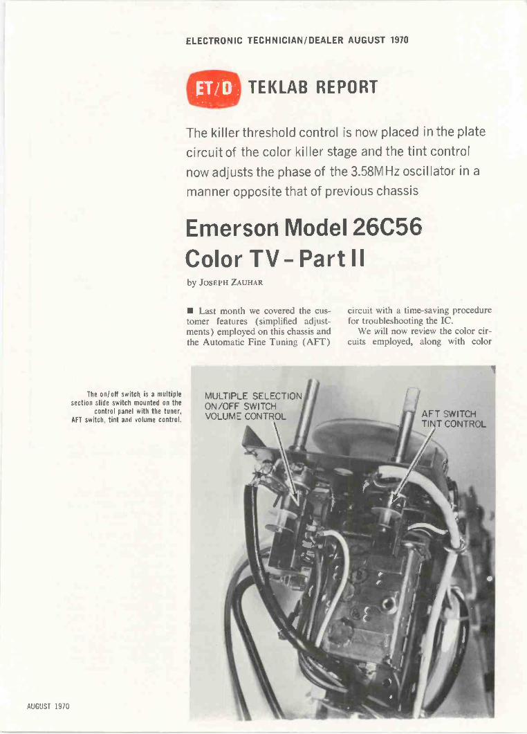
ELECTRONIC TECHNICIAN/DEALER AUGUST 1970
The on/off switch is a multiplesection slide switch mounted on the
control panel with the tuner,AFT switch, tint and volume control.
AUGUST 1970
TEKLAB REPORT
The killer threshold control is now placed in the plate
circuit of the color killer stage and the tint control
now adjusts the phase of the 3.58MHz oscillator in a
manner opposite that of previous chassis
Emerson Model 26C56Color TV- Part IIby JOSEPH ZAUHAR
Last month we covered the cus-tomer features (simplified adjust-ments) employed on this chassis andthe Automatic Fine Tuning (AFT)
circuit with a time -saving procedurefor troubleshooting the IC.
We will now review the color cir-cuits employed, along with color
MULTIP_E SELECTIONON/OFF SWITCHVOLUME CONTROL
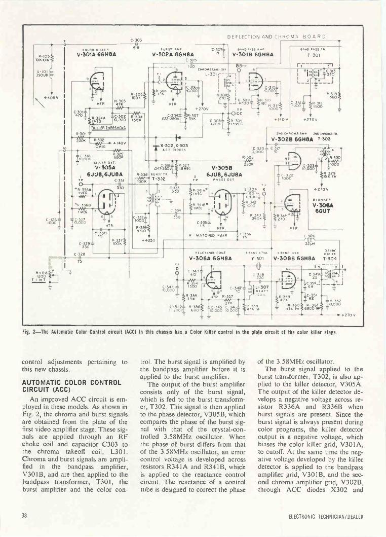
R-105101
L-10139001-1
+ 405 V
C-303
GLOP KILLER
V -301A 6GH8A
HTR
IF -6 8
R-305100K .
R-30347K
470C-304.-
11R -324A!MEG
-C-302TI0,000
tKILLER THRESHOLD
R-301
R-302
IKILLER OFT.
.4vv-304150K
-(
DEFLECTION AND :iiROMA BOARD
BURST AMP C-307V -302A 6GH8A IS I
- 3,5120
CNROMA TAKE -OIL
2
R4*6 5 00.0001C.30611
HIP
BAND PA, AR,' BAND PASS TR.
V-3018 6GH8A 1-301
L -30I r- -I
R-3270
+270V
C-304fiR- 307033-250VL. 39K
10 MEG
V -305A,6JU8,6JU8A
TP C-331II
330*R 336A'MEG
*R-3368
- MEG
C10 -12600 i0,37000
C-323329830 T
C
R-10 81200
TINT
3
+140V
RanTX -302,X-303ACC DIODES
C-319047-250
R-338 BURS' TR.-VW-*
100 K1-342
6 5
HTR
C-33015
92
la13
R-3271 8MEG
5 j3 C-3- 33330
2 C 334
C 3321 3- 3010001
R-3391000
TP
A:*
C-30814700 5MEG
BBTP
Al
6
I
4C 3009
70
TPCC
r,
C 310110.0(xl
R 310180
1000
1 111
L_?
C-312 R-31210001 1500
C.313330
J I--JR-313
560
R 309 +140V +270V
230 Cm ROMA AMP 2NO MICRO TR.
V-3026 60H8A 1-303C 320 _ C 321
10.000 10
R-328
2201V-3058 IS :(388I
6JU8,6JU8APHASE DET
91
+405V
R 341A*IMEG
R 3418*iMEG
1
C-335-1-5 T
L-304 K
MTR.
* MATCHED PAIR
681./H
R 3421000
R 343
10336
3901
0
01
C 322T 1000
HIP
R-329
+270V
RI ANKER
V 306A66U7
1.- 306
II
75TR
C34110,000T
It }A -35533K
C - 342" R-35.1 2001 680
REACTANCE CONT
V -308A 613H8A
22LiH
3.5814COSC TR
Y-301 V-3086 6GH8A T-304-101-6 1
C-3434.0 C-348I9 220 3
C -119;j1vWR-3541500
SSBMC leTAL 3 S8MC OSC
t I 1 c 3541168
levrHTR R'35C-3'4C7"..
s REACT
p.-7.,340 RC8 0133 5;lIC 345 v2IC734E.K10,000 10,000T
S58C-352
10,000
+ 270 V
Fig. 2-The Automatic Color Control circuit (ACC) in this chassis has a Color Killer control in the plate circuit of the color killer stage.
control adjustments pertaining tothis new chassis.
AUTOMATIC COLOR CONTROLCIRCUIT (ACC)
An improved ACC circuit is em-ployed in these models. As shown inFig. 2, the chroma and burst signalsare obtained from the plate of thefirst video amplifier stage. These sig-nals are applied through an RFchoke coil and capacitor C303 tothe chroma takeoff coil, L301.Chroma and burst signals are ampli-fied in the bandpass amplifier,V301B, and are then applied to thebandpass transformer, T301, theburst amplifier and the color con-
trol. The burst signal is amplified bythe bandpass amplifier before it isapplied to the burst amplifier.
The output of the burst amplifierconsists only of the burst signal,which is fed to the burst transform-er, T302. This signal is then appliedto the phase detector, V305B, whichcompares the phase of the burst sig-nal with that of the crystal -con-trolled 3.58MHz oscillator. Whenthe phase of burst differs from thatof the 3.58MHz oscillator, an errorcontrol voltage is developed acrossresistors R341A and R341B, whichis applied to the reactance controlcircuit. The reactance of a controltube is designed to correct the phase
of the 3.58MHz oscillator.The burst signal applied to the
burst transformer, T302, is also ap-plied to the killer detector, V305A.The output of the killer detector de-velops a negative voltage across re-sistor R336A and R336B whenburst signals are present. Since theburst signal is always present duringcolor programs, the killer detectoroutput is a negative voltage, whichbiases the color killer grid, V301A,to cutoff. At the same time the neg-ative voltage developed by the killerdetector is applied to the bandpassamplifier grid, V301B, and the sec-ond chroma amplifier grid, V302B,through ACC diodes X302 and
38 ELECTRONIC TECHNICIAN/DEALER
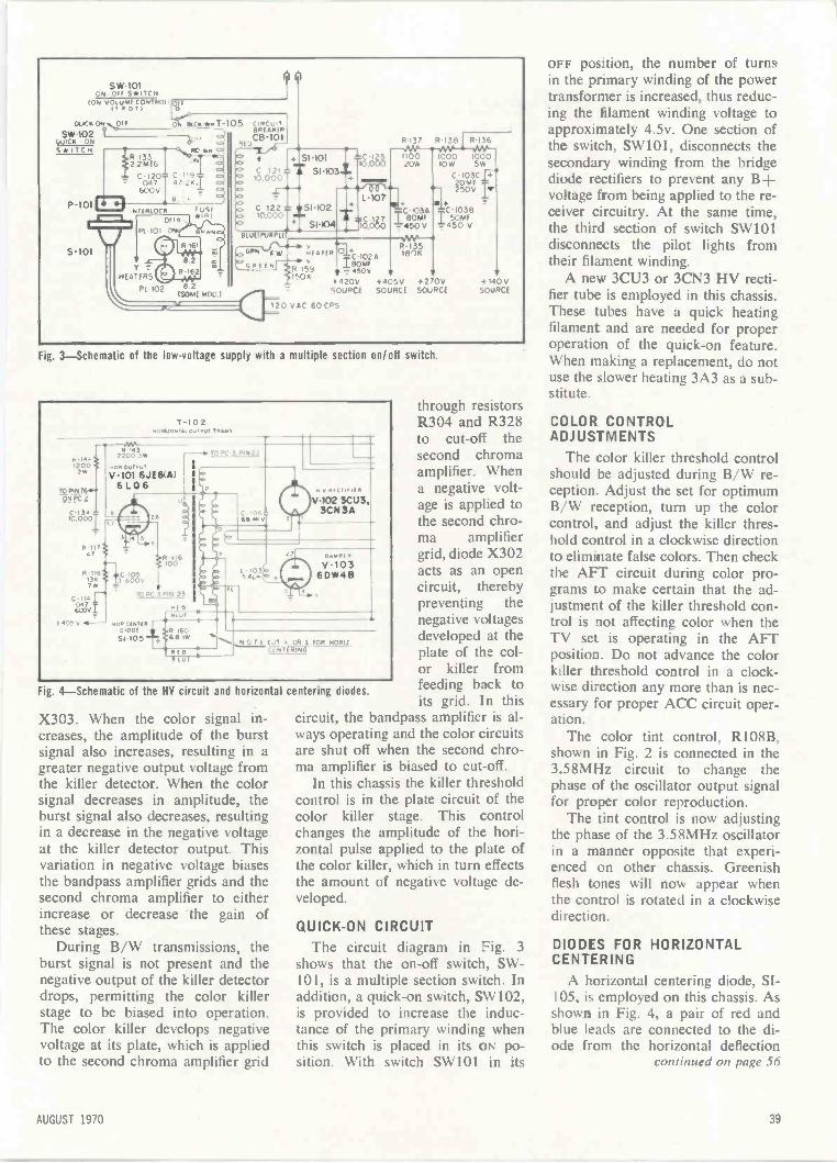
SW.10105.00 SWITCH
ION vOtuME CONTROt (g.17 P o T )
OU1CK ON OFF
SW -102QuicomqSWITCH
P-101
R -I332 2MEG
c047
600V
&:"RC *),uN
C 1,947-241
8
S-101
NTERIOCX
OUR
PE 101
Y
HEATERS
PI. 102
I uSf*141
6.45RI
82(SOME MOO.)
ON &Co -8,87-105 C,RCo,T811EFilp
RtDC8-101
+ SI.101Oo C 121 T slice10,000
C I22 L IIVSI-102,0.000T.# SI-104
8111SPURPlt
c6 NILO 61fC.102AGREEN
15"18064FR,K
# 450v
4;k=1.2.wo_R-136Jn
10,00010W ImOWo
15W
.C-103Cff.
L-107
F6,886
ig!:44+
I03A C-1038BOW I SOME
-450V 450
R-1351804
1420v +405VSOURCE SOURCE
20 VAC 60 CPS
V+270VSOURCE
4 140 VSOURCE
Fig. 3-Schematic of the low -voltage supply with a multiple section on/off switch.
,.)441,00
2W
T-102wNS
R1,17 3
Rid86
°'I-C En,7W
TO PC 3 P,14 25
17v1 Pf 0O 101
22200 3w
V-11 101
6 L 0 6
To PC Af!Ni2
V-102 SCUL3CN3A
1108 mein01001 g R 16051105 68 ig
D
e lot
DAMP(
V-1036DW411
N O T FOR MORIZEN1 RING
Fig. 4-Schematic of the HY circuit and horizontal centering
X303. When the color signal in-creases, the amplitude of the burstsignal also increases, resulting in agreater negative output voltage fromthe killer detector. When the colorsignal decreases in amplitude, theburst signal also decreases, resultingin a decrease in the negative voltageat the killer detector output. Thisvariation in negative voltage biasesthe bandpass amplifier grids and thesecond chroma amplifier to eitherincrease or decrease the gain ofthese stages.
During B/W transmissions, theburst signal is not present and thenegative output of the killer detectordrops, permitting the color killerstage to be biased into operation.The color killer develops negativevoltage at its plate, which is appliedto the second chroma amplifier grid
through resistorsR304 and R328to cut-off thesecond chromaamplifier. Whena negative volt-age is applied tothe second chro-ma amplifiergrid, diode X302acts as an opencircuit, therebypreventing thenegative voltagesdeveloped at theplate of the col-or killer fromfeeding back toits grid. In this
circuit, the bandpass amplifier is al-ways operating and the color circuitsare shut off when the second chro-ma amplifier is biased to cut-off.
In this chassis the killer thresholdcontrol is in the plate circuit of thecolor killer stage. This controlchanges the amplitude of the hori-zontal pulse applied to the plate ofthe color killer, which in turn effectsthe amount of negative voltage de-veloped.
diodes.
QUICK -ON CIRCUIT
The circuit diagram in Fig. 3
shows that the on -off switch, SW -101, is a multiple section switch. Inaddition, a quick -on switch, SW102,is provided to increase the induc-tance of the primary winding whenthis switch is placed in its ON po-sition. With switch SW101 in its
OFF position, the number of turnsin the primary winding of the powertransformer is increased, thus reduc-ing the filament winding voltage toapproximately 4.5v. One section ofthe switch, SW101, disconnects thesecondary winding from the bridgediode rectifiers to prevent any B+voltage from being applied to the re-ceiver circuitry. At the same time,the third section of switch SW101disconnects the pilot lights fromtheir filament winding.
A new 3CU3 or 3CN3 HV recti-fier tube is employed in this chassis.These tubes have a quick heatingfilament and are needed for properoperation of the quick -on feature.When making a replacement, do notuse the slower heating 3A3 as a sub-stitute.
COLOR CONTROLADJUSTMENTS
The color killer threshold controlshould be adjusted during B/W re-ception. Adjust the set for optimumB/W reception, turn up the colorcontrol, and adjust the killer thres-hold control in a clockwise directionto eliminate false colors. Then checkthe AFT circuit during color pro-grams to make certain that the ad-justment of the killer threshold con-trol is not affecting color when theTV set is operating in the AFTposition. Do not advance the colorkiller threshold control in a clock-wise direction any more than is nec-essary for proper ACC circuit oper-ation.
The color tint control, R108B,shown in Fig. 2 is connected in the3.58MHz circuit to change thephase of the oscillator output signalfor proper color reproduction.
The tint control is now adjustingthe phase of the 3.58MHz oscillatorin a manner opposite that experi-enced on other chassis. Greenishflesh tones will now appear whenthe control is rotated in a clockwisedirection.
DIODES FOR HORIZONTALCENTERING
A horizontal centering diode, SI-105, is employed on this chassis. Asshown in Fig. 4, a pair of red andblue leads are connected to the di-ode from the horizontal deflection
continued on page 56
AUGUST 1970 39

Master Antenna Systemsby PHILLIP DAHLEN
Some basic principles of TV signal losses and
channel separation must be understood before installing
the larger, more profitable MATV systems
Large apartment buildings,schools and even some office build-ings offer a lucrative market for theTV technician. Technicians lookingfor additional business can sellapartment owners on the fact thatsuch systems, in this age of color -TV watching, will help make iteasier to rent apartments at higherrates. With greater emphasis on ed-ucational TV, school systems arebecoming more conscious of MATVsystems-particularly if they chooseto make use of special TV channelsnot available to the general public.Even office buildings require suchsystems if executives are to keepabreast of outside current events.
MATV systems used in these ap-plications can be divided into threebasic parts: Antennas for receivingthe desired channels; electronicequipment for amplifying and mod-ifying such signals, as necessary, fordistribution to the receivers; and thesystem for carrying the signals tothe various TV sets that are to re-ceive them.
Since the system must be designedto supply each TV set with the re-quired signal, distribution systemsignal requirements should be calcu-lated first in order to determine thesignal strength required from theother components in the system.
DISTRIBUTION SYSTEMS
The accurate design of a distribu-tion system requires that signal loss-es in each portion of the system beaccounted for in order to be certainthat once the system is constructed,it will supply an adequate signal toeach TV set-without using unnec-essarily expensive components tosupply greater than required signals.
These signal levels and losses aremost frequently measured in decibel
units. If losses were instead given inpercentages, it would be necessaryto multiply signal strength by eachrate of loss encountered in order todetermine the final signal present atthe receiver. However, by insteadusing a logarithmic system of mea-sure, total signal loss can be deter-mined by subtraction, thus simplify-ing calculations.
For MATV systems, the decibel(dB) is defined as being equal to 20
logi 01000µv when the voltage in
question is present across a 75(1 co-
axial cable, or 201og 0 when2000/ivthe voltage is present across a300f1 twin lead. The term E repre-sents the voltage present, while1000p.v represents the standard sig-nal voltage that should be supplieda TV set.
Fortunately, the use of decibelunits does not require an under-standing of the theories of loga-rithms, and conversion between dec-ibels and voltages can be made sim-ply with the use of tables, such asTable 1. [Example: If you have a1778µv signal (5dB) and a 1dB sig-nal loss through a cable, the re-maining signal is 1585µv (4dB),5dB - 1dB = 4dB. Exact decibel-to -voltage conversions are possiblesince they are merely set by defini-tion. However the voltages used inthis article merely represent theseconversions and are to a much high-er degree of accuracy than measure-ments would require, or even gen-erally permit.]
The most significant cause of un-desired signal loss is the coaxial ca-ble or twin lead used to carry the TVsignal from the central system toeach receiver. The signal character-istics of such wire is described in
the article, "The Long and Short ofMATV Cables," on page 53 of theMay issue. Based on the infor-mation in that article, we can con-clude that 7511 coaxial cable ispreferred for MATV use. Since theUHF and VHF antenna terminalsat the back of most TV sets requiresignals from 30011 twin lead, amatching transformer should be se-cured to the back of each set to pro-vide 30011 impedance UHF andVHF signals, as required, from a7511 coaxial cable. A wall outlet(tap off) should also be providednear each set, from which a coaxialcable can supply the TV signal tothe matching transformer (Fig. 1).
Each tap off will result in somesignal distortion and generally a dis-tribution cable should be limited tono more than 15 tap offs. Thus thenumber of TV sets will determinethe number of distribution lines re-quired (two typical cable arrange-ments as shown in Fig. 2).
The general layout for a portionof a typical MATV distribution sys-tem is shown in Fig. 3. The cableshown in this illustration has a perhundred foot signal loss of 3.0dB atVHF channel 13 and 8.0dB at UHFchannel 83. The first 30 -ft sectionof cable, therefore, has a 0.9dBVHF signal loss and a 2.4dB UHFsignal loss (3.0dB X .30, 8.0dBX .30). The signal loss for the re-maining segments of cable can becalculated in the same manner.
The four-way splitter used in thisexample has a 7.0dB VHF signalloss and a 7.7dB UHF signal loss.
If our example distribution sys-tem were long enough to contain 15taps on a single cable, the signal atthe first tap would overload the TVset, while the signal at the end ofthe cable would be too weak for theTV set to handle it. To compensatefor this problem, the taps are de-signed to provide some isolation be-tween the TV sets and the distribu-tion cable-the greatest isolationbeing provided for the first sets,and the least for the last ones. Thesetaps also result in some signal lossin the balance of the cable. Typicalisolation losses and through -linelosses are listed in Table II.
For convenience, the 75f/ coaxialcable between the tap offs and theisolation transformers have the same
40 ELECTRONIC TECHNICIAN, DEALER
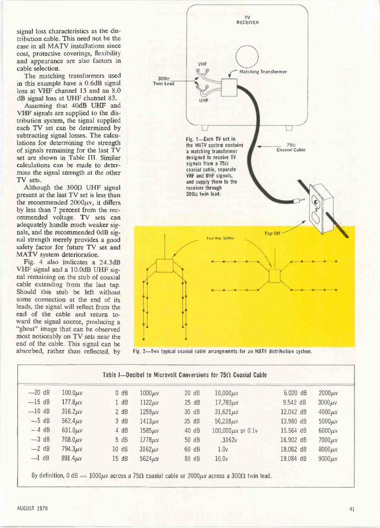
TVRECEIVER
signal loss characteristics as the dis-tribution cable. This need not be thecase in all MATV installations sincecost, protective coverings, flexibilityand appearance are also factors incable selection.
The matching transformers usedin this example have a 0.6dB signalloss at VHF channel 13 and an 8.0dB signal loss at UHF channel 83.
Assuming that 40dB UHF andVHF signals are supplied to the dis-tribution system, the signal suppliedeach TV set can be determined bysubtracting signal losses. The calcu-lations for determining the strengthof signals remaining for the last TVset are shown in Table III. Similarcalculations can be made to deter-mine the signal strength at the otherTV sets.
Although the 30011 UHF signalpresent at the last TV set is less thanthe recommended 200011v, it differsby less than 7 percent from the rec-ommended voltage. TV sets canadequately handle much weaker sig-nals, and the recommended 0dB sig-nal strength merely provides a goodsafety factor for future TV set andMATV system deterioration.
Fig. 4 also indicates a 24.3dBVHF signal and a 10.0dB UHF sig-nal remaining on the stub of coaxialcable extending from the last tap.Should this stub be left withoutsome connection at the end of itsleads, the signal will reflect from theend of the cable and return to-ward the signal source, producing a"ghost" image that can be observedmost noticeably on TV sets near theend of the cable. This signal can beabsorbed, rather than reflected, by
30011Twin Lead
VHF
Matching Transformer
Fig. 1-Each TV set inthe MATV system containsa matching transformerdesigned to receive TVsignals from a 75t2coaxial cable, separateVHF and UHF signals,and supply them to thereceiver through30012 twin lead.
Four.Way Splitter
75s?Coaxial Cable
Tap Off \t>
Fig. 2-Two typical coaxial cable arrangements for an MATV distribution system.
Table I-Decibel to Microvolt Conversions for 7512 Coaxial Cable
-20 dB 100.0/1v 0 dB 1000µ,v 20 dB 10,000tiv 6.020 dB 20000-15 dB 177.8,av 1 dB 1122µv 25 dB 17,783pv 9.542 dB 3000pv
-10 dB 316.2pv 2 dB 1259pv 30 dB 31,621pv 12.042 dB 4000,uv
-5 dB 562.4pv 3 dB 1413pv 35 dB 56,238pv 13.980 dB 5000pv
-4 dB 631.0µv 4 dB 1585pv 40 dB 100,000pv or 0.1v 15.564 dB 6000/2v
-3 dB 708.0pv 5 dB 1778,uv 50 dB .3162v 16.902 dB 7000pv
-2 dB 794.3µv 10 dB 3162,uv 60 dB 1.0v 18.062 dB 8000pv
-1 dB 891.4pv 15 dB 5624pv 80 dB 10.0v 19.084 dB 9000,uv
By definition, 0 dB - 1000pv across a 751/ coaxial cable or 2000pm across a 3001/ twin lead.
AUGUST 1970 41
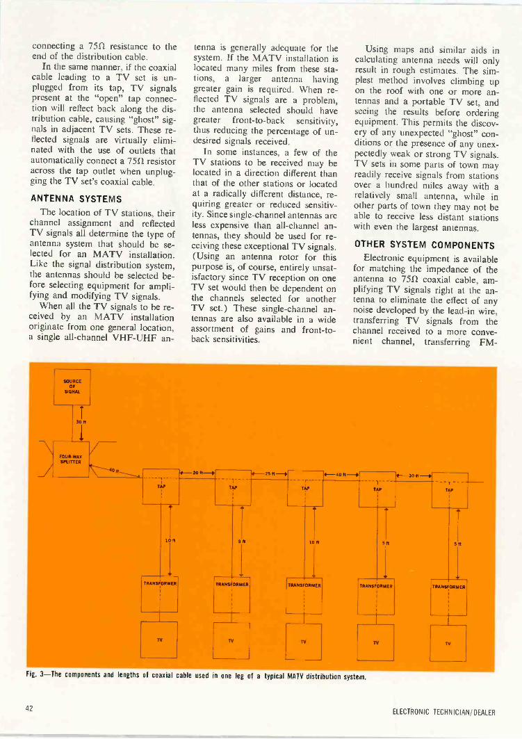
connecting a 75f/ resistance to theend of the distribution cable.
In the same manner, if the coaxialcable leading to a TV set is un-plugged from its tap, TV signalspresent at the "open" tap connec-tion will reflect back along the dis-tribution cable, causing "ghost" sig-nals in adjacent TV sets. These re-flected signals are virtually elimi-nated with the use of outlets thatautomatically connect a 7551 resistoracross the tap outlet when unplug-ging the TV set's coaxial cable.
ANTENNA SYSTEMS
The location of TV stations, theirchannel assignment and reflectedTV signals all determine the type ofantenna system that should be se-lected for an MATV installation.Like the signal distribution system,the antennas should be selected be-fore selecting equipment for ampli-fying and modifying TV signals.
When all the TV signals to be re-ceived by an MATV installationoriginate from one general location,a single all -channel VHF -UHF an-
tenna is generally adequate for thesystem. If the MATV installation islocated many miles from these sta-tions, a larger antenna havinggreater gain is required. When re-flected TV signals are a problem,the antenna selected should havegreater front -to -back sensitivity,thus reducing the percentage of un-desired signals received.
In some instances, a few of theTV stations to be received may belocated in a direction different thanthat of the other stations or locatedat a radically different distance, re-quiring greater or reduced sensitiv-ity. Since single -channel antennas areless expensive than all -channel an-tennas, they should be used for re-ceiving these exceptional TV signals.(Using an antenna rotor for thispurpose is, of course, entirely unsat-isfactory since TV reception on oneTV set would then be dependent onthe channels selected for anotherTV set.) These single -channel an-tennas are also available in a wideassortment of gains and front -to-back sensitivities.
Using maps and similar aids incalculating antenna needs will onlyresult in rough estimates. The sim-plest method involves climbing upon the roof with one or more an-tennas and a portable TV set, andseeing the results before orderingequipment. This permits the discov-ery of any unexpected "ghost" con-ditions or the presence of any unex-pectedly weak or strong TV signals.TV sets in some parts of town mayreadily receive signals from stationsover a hundred miles away with arelatively small antenna, while inother parts of town they may not beable to receive less distant stationswith even the largest antennas.
OTHER SYSTEM COMPONENTS
Electronic equipment is availablefor matching the impedance of theantenna to 751.1 coaxial cable, am-plifying TV signals right at the an-tenna to eliminate the effect of anynoise developed by the lead-in wire,transferring TV signals from thechannel received to a more conve-nient channel, transferring FM -
SOURCEOF
SIGNAL
30 ft
FOUR WAYSPUTTER7 4-20 ft -4
TAP
10 ft
TRANSFORMER
25 R-4TAP
5R
rTAP
4-40 ft-,
10 ft
TRANSFORMER
1
TAP
4-30 ft -4
5R
TRANSFORMER
TAP
SR
TRANSFORMER
TV
Fig. 3-The components and lengths of coaxial cable used in one leg of a typical MATV distribution system.
42ELECTRONIC TECHNICIAN/DEALER
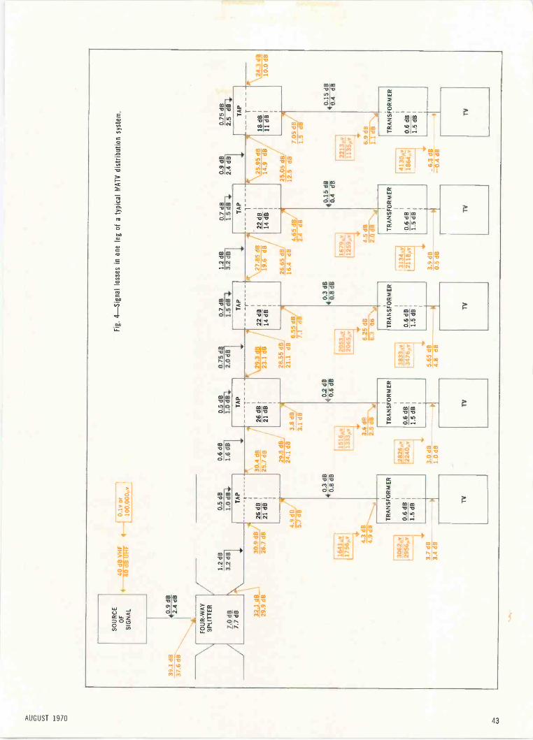
SO
UR
CE
OF
SIG
NA
L
TO
.9dB
2.4
dB
FO
UR
-WA
Y3P
LIT
TE
R
7.0
dg7.
7 dB 32
.1 d
B
40 d
B V
HF
0.1v
or
44-
40 d
B U
HF
100,
000,
.v
29.9
dB
1.2
dB3.
2 dB
30.9
dB
j."
26.7
dB
[761
.71y
1756
v
Fig
. 4 -
Sig
nal l
osse
s in
one
leg
of a
typi
cal M
AT
V d
istr
ibut
ion
syst
em.
0.5
dB0.
608
0.5
dB07
5d0.
7 dB
1.2
dB0.
7 dB
0.9
dB0.
75 d
B1.
0 dB
1.6
dBi
1.0
d82,
0 dB
1.5c
33.2
d13
1 5M
112.
4
dBi
2.5
d8T
AP
26 d
B21
dB
4.9
dB
4.3
dB4.
9 dB
[306
2,4y
2956
pY
0.3
dB40
.8 d
B
TR
AN
SF
OR
ME
R
0.6
dB1.
5 dB
30.4
dB
25.7
dB
29.8
dB
TA
P
26 d
B21
dB
24.1
dB
3.8
dB3.
1 dB
0.2
dB40
.6 d
B
1333
vI
2826
pvi
2240
pv
3.0
dB1.
0 dB
3.8
dR2.
5 dB T
RA
NS
FO
RM
ER
0.6
dB1.
5 dB
TV
29.3
dB
23.1
dB
28.5
5 dB
21.1
dB6.
55 d
B '
7.1
dR
TA
P r
22 d
B14
dB
5.65
dB
4.8
dB
0.3
dB4
-ox
-de
6.25
dB
r313
t3a
TR
AN
SF
OR
ME
R
0.6
dB1.
5 dB
TV
27.8
5 dB
19.6
dB
26.6
5 dB
,
TA
P
22 d
B14
dB
16.4
dB4.
652
1679
,1,
1259
,v
3134
µv21
18,v
3.9
dB0.
5 dB
4.5
dB2.
0 dB
N.,
\25.
95dB
14.9
dB
25.0
5 dB
12.5
dB
0 15
dB
4.0.
4 dB
TR
AN
SF
OR
ME
R
0.6
dB1.
5 dB
TV
TA
P
18 d
B11
dB
7.05
dBi
1.5
dB
[221
3,,v
1135
v
1413
0, v
i18
64v
6.3
dB0.
4 dB
6.9
dB1.
1 dB
\
j!.
\ 24.
3 dB
10.0
dB
0.15
dB
40.4
dB
TR
AN
SF
OR
ME
R
0.6
dB1.
5 dB
TV
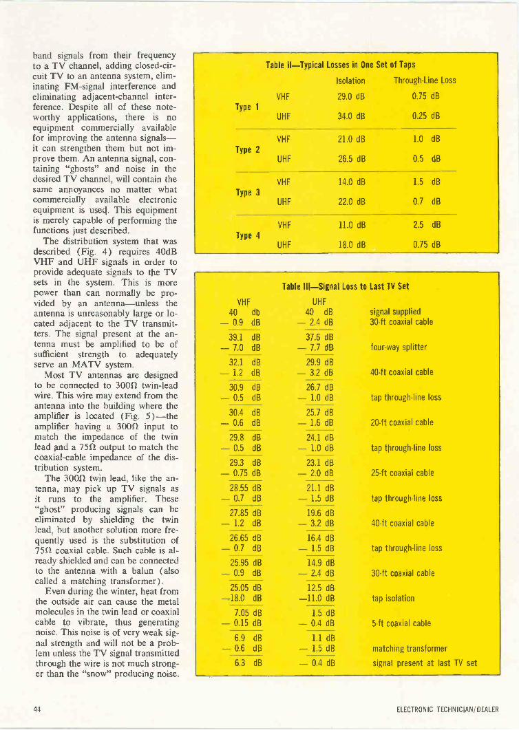
band signals from their frequencyto a TV channel, adding closed-cir-cuit TV to an antenna system, elim-inating FM -signal interference andeliminating adjacent -channel inter-ference. Despite all of these note-worthy applications, there is noequipment commercially availablefor improving the antenna signals -it can strengthen them but not im-prove them. An antenna signal, con-taining "ghosts" and noise in thedesired TV channel, will contain thesame annoyances no matter whatcommercially available electronicequipment is used. This equipmentis merely capable of performing thefunctions just described.
The distribution system that wasdescribed (Fig. 4) requires 40dBVHF and UHF signals in order toprovide adequate signals to the TVsets in the system. This is morepower than can normally be pro-vided by an antenna -unless theantenna is unreasonably large or lo-cated adjacent to the TV transmit-ters. The signal present at the an-tenna must be amplified to be ofsufficient strength to adequatelyserve an MATV system.
Most TV antennas are designedto be connected to 30051 twin -leadwire. This wire may extend from theantenna into the building where theamplifier is located (Fig. 5) -theamplifier having a 30012 input tomatch the impedance of the twinlead and a 7551 output to match thecoaxial -cable impedance of the dis-tribution system.
The 30011 twin lead, like the an-tenna, may pick up TV signals asit runs to the amplifier. These"ghost" producing signals can beeliminated by shielding the twinlead, but another solution more fre-quently used is the substitution of7551 coaxial cable. Such cable is al-ready shielded and can be connectedto the antenna with a balun (alsocalled a matching transformer).
Even during the winter, heat fromthe outside air can cause the metalmolecules in the twin lead or coaxialcable to vibrate, thus generatingnoise. This noise is of very weak sig-nal strength and will not be a prob-lem unless the TV signal transmittedthrough the wire is not much strong-er than the "snow" producing noise.
Type 1
Table II -Typical Losses in One Set of Taps
Isolation Through -Line Loss
VHF 29.0 dB 0.75 dB
UHF 34.0 dB 0.25 dB
VHF 21.0 dB 1.0 dB
Type 2UHF 26.5 dB 0.5 dB
VHF 14.0 dB 1.5 dB
Type 3UHF 22.0 dB 0.7 dB
VHF 11.0 dB 2.5 dB
Type 4UHF 18.0 dB 0.75 dB
Table III -Signal Loss to Last TV Set
VHF UHF
40 db 40 dB
- 0.9 dB - 2.4 dB
39.1 dB
- 7.0 dB
32.1 dB
- 1.2 dB
30.9 dB- 0.5 dB
30.4 dB
- 0.6 dB
29.8 dB
- 0.5 dB
29.3 dB
- 0.75 dB
28.55 dB- 0.7 dB
27.85 dB- 1.2 dB
26.65 dB- 0.7 dB
25.95 dB- 0.9 dB
25.05 dB-18.0 dB
7.05 dB- 0.15 dB
6.9 dB
- 0.6 dB
signal supplied30 -ft coaxial cable
37.6 dB- 7.7 dB four-way splitter
29.9 dB- 3.2 dB 40 -ft coaxial cable
26.7 dB- 1.0 dB tap through -line loss
25.7 dB- 1.6 dB 20 -ft coaxial cable
24.1 dB- 1.0 dB tap through -line loss
23.1 dB- 2.0 dB 25 -ft coaxial cable
21.1 dB- 1.5 dB tap through -line loss
19.6 dB- 3.2 dB 40 -ft coaxial cable
16.4 dB- 1.5 dB tap through -line loss
14.9 dB- 2.4 dB 30 -ft coaxial cable
12.5 dB-11.0 dB tap isolation
1.5 dB- 0.4 dB 5 -ft coaxial cable
1.1 dB- 1.5 dB matching transformer
6.3 dB - 0.4 dB signal present at last TV set
44 ELECTRONIC TECHNICIAN/ DEALER
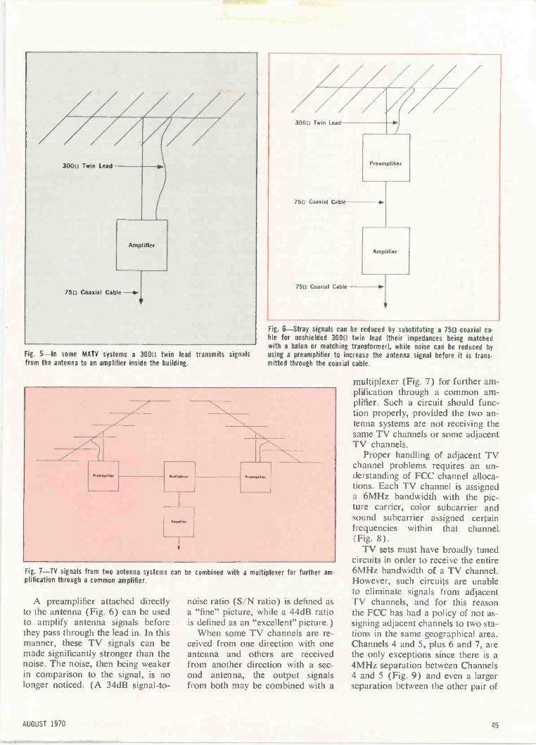
300t.i Twin Lead
Amplifier
75..2 Coaxial Cable
300fl Twin Lead
75t: Coaxial Cable --ow
Amplifier
75u Coaxial Cable
Fig. 6-Stray signals can be reduced by substituting a 7512 coaxial ca-ble for unshielded 300i.! twin lead (their impedances being matchedwith a balun or matching transformer), while noise can be reduced by
Fig. 5-In some MATV systems a 3001 twin lead transmits signals using a preamplifier to increase the antenna signal before it is trans-mitted through the coax al cable.from the antenna to an amplifier inside the building.
L
Fig. 7-TV signals from two antenna systems can be combined with a multiplexer for further am-plification through a common amplifier.
A preamplifier attached directlyto the antenna (Fig. 6) can be usedto amplify antenna signals beforethey pass through the lead in. In thismanner, these TV signals can bemade significantly stronger than thenoise. The noise, then being weakerin comparison to the signal, is nolonger noticed. (A 34dB signal-to-
noise ratio (S/N ratio) is defined asa "fine" picture, while a 44dB ratiois defined as an "excellent" picture.)
When some TV channels are re-ceived from one direction with oneantenna and others are receivedfrom another direction with a sec-ond antenna, the output signalsfrom both may be combined with a
multiplexer (Fig. 7) for further am-plification through a common am-plifier. Such a circuit should func-tion properly, provided the two an-tenna systems are not receiving thesame TV channels or some adjacentTV channels.
Proper handling of adjacent TVchannel problems requires an un-derstanding of FCC channel alloca-tions. Each TV channel is assigneda 6MHz bandwidth with the pic-ture carrier, color subcarrier andsound subcarrier assigned certainfrequencies within that channel(Fig. 8).
TV sets must have broadly tunedcircuits in order to receive the entire6MHz bandwidth of a TV channel.However, such circuits are unableto eliminate signals from adjacentTV channels, and for this reasonthe FCC has had a policy of not as-signing adjacent channels to two sta-tions in the same geographical area.Channels 4 and 5, plus 6 and 7, arethe only exceptions since there is a4MHz separation between Channels4 and 5 (Fig. 9) and even a largerseparation between the other pair of
AUGUST 1970 45
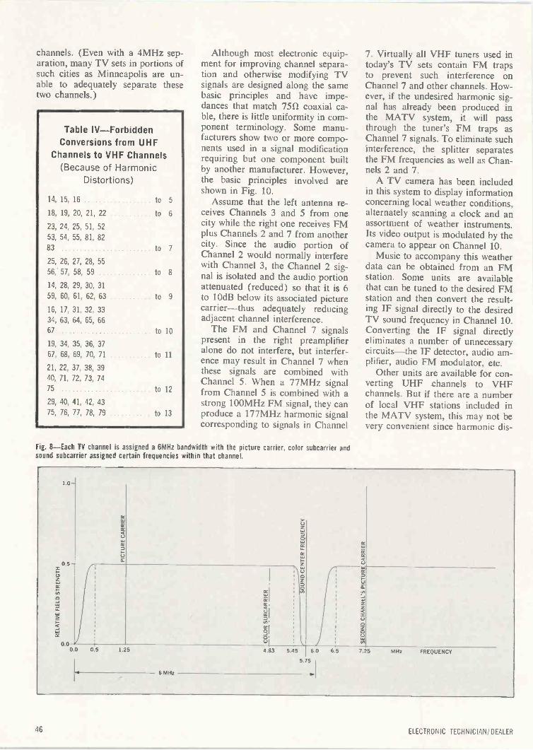
channels. (Even with a 4MHz sep-aration, many TV sets in portions ofsuch cities as Minneapolis are un-able to adequately separate thesetwo channels.)
Table IV -ForbiddenConversions from UHF
Channels to VHF Channels(Because of Harmonic
Distortions)
14, 15, 16
18, 19, 20, 21, 22
23, 24, 25, 51, 52
53, 54, 55, 81, 82
83
25, 26, 27, 28, 55
56: 57, 58, 59
14, 28, 29, 30, 31
59, 60, 61, 62, 63
16, 17, 31, 32, 33
34, 63, 64, 65, 66
67
19, 34, 35, 36, 37
67, 68, 69, 70, 71
21, 22, 37, 38, 39
40, 71, 72, 73, 74
75
29, 40, 41, 42, 43
75, 76, 77, 78, 79
to 5
. to 6
to 7
to 8
to 9
to 10
to 11
to 12
to 13
Although most electronic equip-ment for improving channel separa-tion and otherwise modifying TVsignals are designed along the samebasic principles and have impe-dances that match 7552 coaxial ca-ble, there is little uniformity in com-ponent terminology. Some manu-facturers show two or more compo-nents used in a signal modificationrequiring but one component builtby another manufacturer. However,the basic principles involved areshown in Fig. 10.
Assume that the left antenna re-ceives Channels 3 and 5 from onecity while the right one receives FMplus Channels 2 and 7 from anothercity. Since the audio portion ofChannel 2 would normally interferewith Channel 3, the Channel 2 sig-nal is isolated and the audio portionattenuated (reduced) so that it is 6to 10dB below its associated picturecarrier -thus adequately reducingadjacent channel interference.
The FM and Channel 7 signalspresent in the right preamplifieralone do not interfere, but interfer-ence may result in Channel 7 whenthese signals are combined withChannel 5. When a 77MHz signalfrom Channel 5 is combined with astrong 100MHz FM signal, they canproduce a 177MHz harmonic signalcorresponding to signals in Channel
Fig. 8 -Each TV channel is assigned a 6MHz bandwidth with the picture carrier, color subcarrier andsound subcarrier assigned certain frequencies within that channel.
7. Virtually all VHF tuners used intoday's TV sets contain FM trapsto prevent such interference onChannel 7 and other channels. How-ever, if the undesired harmonic sig-nal has already been produced inthe MATV system, it will passthrough the tuner's FM traps asChannel 7 signals. To eliminate suchinterference, the splitter separatesthe FM frequencies as well as Chan-nels 2 and 7.
A TV camera has been includedin this system to display informationconcerning local weather conditions,alternately scanning a clock and anassortment of weather instruments.Its video output is modulated by thecamera to appear on Channel 10.
Music to accompany this weatherdata can be obtained from an FMstation. Some units are availablethat can be tuned to the desired FMstation and then convert the result-ing IF signal directly to the desiredTV sound frequency in Channel 10.Converting the IF signal directlyeliminates a number of unnecessarycircuits -the IF detector, audio am-plifier, audio FM modulator, etc.
for con-verting UHF channels to VHFchannels. But if there arc a numberof local VHF stations included inthe MATV system, this may not bevery convenient since harmonic dis-
1 0-
0,5
z
LT.
cc
0.00.0
CC
cc
C
0.5 1.25
6 MHz
5.45 6.0 65
5.75
7.25 MHz FREQUENCY
46 ELECTRONIC TECHNICIAN/DEALER
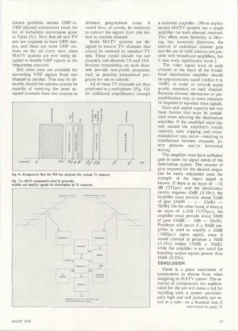
tortion prohibits certain UHF -to -VHF channel conversions (note thelist of forbidden conversions givenin Table IV). Now that all new TVsets are required to have UHF tun-ers, and there are more UHF sta-tions on the air every year, mostMATV systems are now being de-signed to handle UHF signals at thefrequencies received.
Still other units are available forconverting VHF signals from onechannel to another. This may be de-sirable should the antenna system becapable of receiving the same as-signed channels from two stations in
different geographical areas. Itwould then, of course, be necessaryto convert the signals from one sta-tion to another channel.
Some MATV systems are de-signed to receive TV channels thatcannot be received by standard TVsets. These would include the subchannels and channels 7A and 13A.Stations transmitting on such chan-nels provide non-public programs,such as possibly educational pro-grams for use in schools.
All of these TV channels are thencombined in a multiplexer (Fig. 10)for additional amplification through
2
Frequency <2
03
92°MHz
Fig. 9-Frequencies that the FCC has assigned the various TV dannels.
Fig. 10-MATV components used to generate,modify and amplify signals for distribution to TV receivers.
Channels 3 and S
Proansphher
3 and 5
10
FM plus Channels 2 and 7
Aftenualer
Multmleeee
Ansphler
Channels 2 3
sphlter and d
10
ps-Hi"
FM
COnverler
And 10 to lean waybut.on sysiem
a common amplifier. (More sophis-ticated MATV systems use a singleamplifier for each channel received.This offers more flexibility in filter-ing, less harmonic distortion, thecontrol of individual channel gainand the use of AGC circuits not pos-sible with broadband amplifiers, butit also costs significantly more.)
The video signal level of eachchannel at the input of the broad-band distribution amplifier shouldbe approximately equal (within 6 to10dB) in order to provide equalquality reception on each channel.Separate channel attenuation or pre -amplification may in some instancesbe required to equalize these signals.
Gain and output capacity are twobasic factors that must be consid-ered when selecting the distributionamplifier. If the amplified input sig-nals exceed the amplifier's outputcapacity, sync clipping and cross -modulation may occur-resulting ininterference between channels, jit-tery pictures and/or horizontaltearing.
The amplifier must have sufficientgain to meet the signal needs of thedistribution The amount ofgain required for the desired outputcan be easily calculated once thestrength of the input signal isknown. If there is an input of -12dB (251µv) and the distributionsystem requires 40dB (0.10v), theamplifier must provide about 52dBof gain [40dB - (- 12dB) ----52dB[. On the other hand, if there isan input of +2dB (1259µv), theamplifier must provide about 38dBof gain (40dB - 2dB 38dB).Problems will result if a 50dB am-plifier is used to amplify a 20dB(1000µv) input signal, since itwould attempt to produce a 70dB( 3.16v ) output (50dB + 20dB )while the amplifier is not rated forhandling output signals greater than50dB (0.32v).CONCLUSION
There is a great assortment ofcomponents to choose from whendesigning an MATV system. The se-lection of components too sophisti-cated for the job will make a bid forinstalling such a system unrealisti-cally high and will probably not re-sult in a sale-or a financial loss if
continued on page 75
AUGUST 1970 47
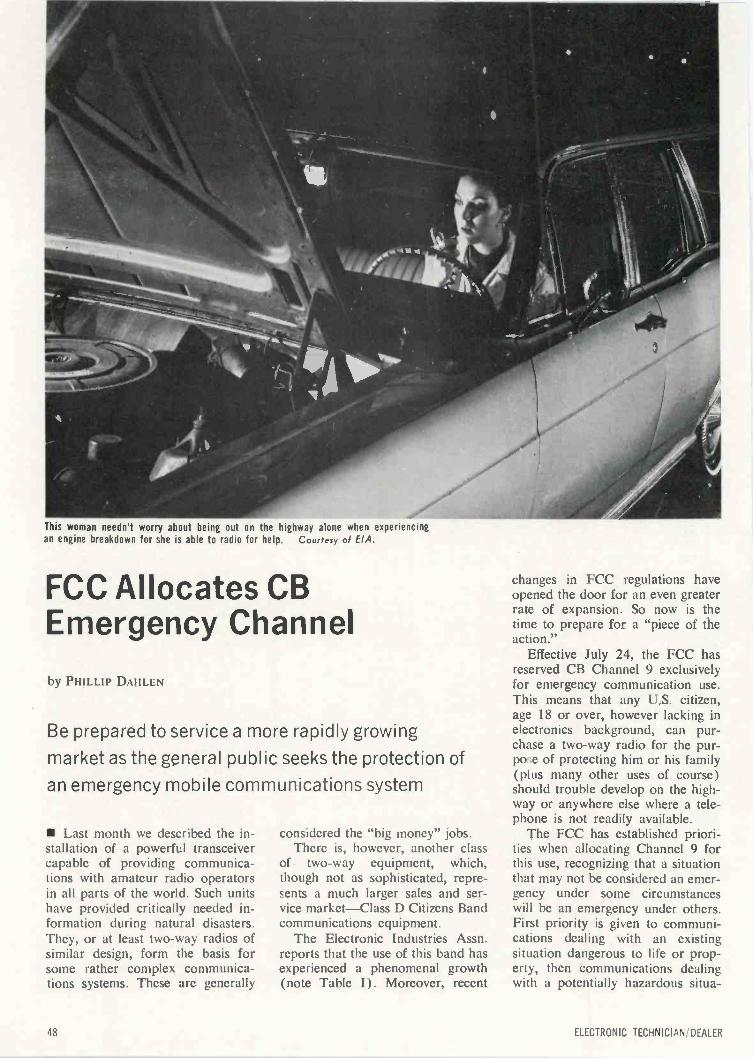
This woman needn't worry about being out on the highway alone when experiencingan engine breakdown for she is able to radio for help. Courtesy of EIA.
FCC Allocates CBEmergency Channel
by PHILLIP DAHLEN
Be prepared to service a more rapidly growing
market as the general public seeks the protection of
an emergency mobile communications system
Last month we described the in-stallation of a powerful transceivercapable of providing communica-tions with amateur radio operatorsin all parts of the world. Such unitshave provided critically needed in-formation during natural disasters.They, or at least two-way radios ofsimilar design, form the basis forsome rather complex communica-tions systems. These are generally
considered the "big money" jobs.There is, however, another class
of two-way equipment, which,though not as sophisticated, repre-sents a much larger sales and ser-vice market-Class D Citizens Bandcommunications equipment.
The Electronic Industries Assn.reports that the use of this band hasexperienced a phenomenal growth(note Table I). Moreover, recent
changes in FCC regulations haveopened the door for an even greaterrate of expansion. So now is thetime to prepare for a "piece of theaction."
Effective July 24, the FCC hasreserved CB Channel 9 exclusivelyfor emergency communication use.This means that any U.S. citizen,age 18 or over, however lacking inelectronics background, can pur-chase a two-way radio for the pur-po ;e of protecting him or his family(plus many other uses of course)should trouble develop on the high-way or anywhere else where a tele-phone is not readily available.
The FCC has established priori-ties when allocating Channel 9 forthis use, recognizing that a situationthat may not be considered an emer-gency under some circumstanceswill be an emergency under others.First priority is given to communi-cations dealing with an existingsituation dangerous to life or prop-erty, then communications dealingwith a potentially hazardous situa-
48 ELECTRONIC TECHNICIAN/DEALER

Fortunately the first ono to wive at the scene of this accident was equippedwith CB Channel 9 emergency communications equipment. Courtesy of EIA.
tion, then road assistance for a dis-abled vehicle on a street or highway,and finally to street directions.
The FCC was very specific inspecifying that this channel will berestricted exclusively for this use.After emergency communicationshave been established on that chan-nel, it may be continued on thesame channel if absolutely neces-sary. But whenever possible, bothparties should switch to anotherchannel once contact has been madein order to free the channel forother emergency contacts.
As indicated in the EIA FactSheet, there are now more than2000 volunteer organizations, plusmany fire departments and policestations, monitoring Channel 9 andready to accept emergency calls anytime of the day. However, the FCCmakes it clear that none of thesegroups can consider Channel 9 ex-clusively theirs for emergency use.It is available to everyone with alicensed CB transceiver.
In some states two-way communi-
cations are not legal while hunting,the authorities feeling that this leadsto unsportsmanlike practices. How-ever, this does not mean that a CBtransceiver should not be broughtalong just in case an emergency re-quires calling for help-a hunter be-coming ill, injured or lost.
CB transceivers can also be usedon boats for emergency communica-tions (in addition to more casualcommunications, of course). Thereis, however, both a plus and a minusfactor concerning the use of thisband for such communications.There is a Marine Band availablefor use on boats, and this band ismonitored by the Coast Guard forproviding emergency assistance. TheCoast Guard is too busy monitoringthis band to install CB equipmentand attempt to monitor that band aswell-so they will not be there torespond directly to your CB call forhelp. On the other hand, the MarineBand is already overcrowded and attimes more jammed than the non -emergency portion of the CB band.
For this reason, it is quite possiblethat a distress call received by a CBoperator will be forwarded to theCoast Guard by telephone before itis possible to make direct contact onthe Marine Band.
Car owners will be the first to re-spond to the added protection re-sulting from a CB installation, andauto installations will constitute thebulk of future CB transceiver salesand maintenance. These CB unitscan do much more than help assurethe driver that communication isavailable when there is an accidentor breakdown. As a personal exam-ple: There have been a number oftimes when I have driven my caracross country accompanied bysomeone driving another vehicle.From personal experience I can saythat it can become rather frighteningwhen you are driving the second car,following some distance behind ona super highway and then remem-ber that your car has a smaller gastank than that of the other driver. Itis also no fun when driving through
AUGUST 1970 49

a strange city and having to wait fora red light, as the car ahead con-tinues on, making a turn some dis-tance down the road. If nothing else,you can at least use the CB trans-ceiver to yell "stop" to the otherdriver.
It is hoped that this month's ar-ticle has made you aware of a "gold-en opportunity" that has resultedfrom the recent change in FCC reg-ulations. Let's take advantage ofthis situation by selling, installingand maintaining CB equipment.
We plan on providing additionalinformation in future articles, but inthe meantime please feel free tocontact us if we can be of any ad-ditional help.
Station attendant receiving Channel 9 roadservice request Couresy of EIA.
Table I-Citizens Two -Way Radio
EIA Fact Sheet
More than 3,500,000 5-w CB two-way radios have been purchasedby Americans for business and personal use.
1,359,355 CB licenses have been granted by the FCC.1 out of every 60 cars on the road today already is equippedwith a CB radio.
An estimated 1,800,000 emergencies were reported last year viaCB radio.
An estimated 72% of the emergencies handled involved auto-motive accidents or other automotive emergencies.
Over 2000 volunteer organizations provide 24 -hour -a -day moni-toring to accept emergency calls on Channel 9.
An estimated 500 police and fire departments now monitor CBradio for emergencies.
73% of the licenses issued last year were for personal commu-nications uses.
Typical personal communications uses include:Marine pleasure craftHunting, fishing, campingPersonal safety, vehiclesVolunteers, civil defense and fireShut-ins, chronic medical problemsHome to vehicle communications
27% of the licenses issuea last year were for business -profes-sional communications uses.
Major users were:Farm, 15.3%Civic/municipal, 16.1%Service business, 15.7%Medical, 6.0%Manufacturing business, 2.4%Miscellaneous -construction. sales, etc.. 44.5%
ELECTRONIC TECHNICIAN, DEALER
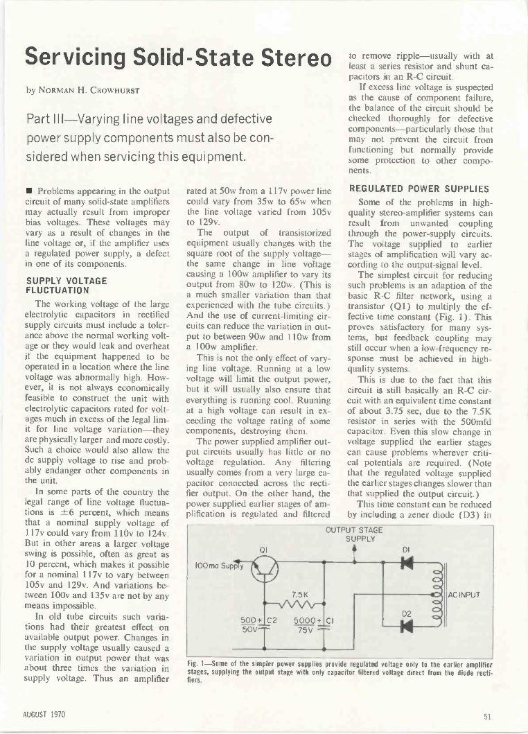
Servicing Solid -State Stereoby NORMAN H. CROWHURST
Part III-Varying line voltages and defective
power supply components must also be con-
sidered when servicing this equipment.
Problems appearing in the outputcircuit of many solid-state amplifiersmay actually result from improperbias voltages. These voltages mayvary as a result of changes in theline voltage or, if the amplifier usesa regulated power supply, a defectin one of its components.
SUPPLY VOLTAGEFLUCTUATION
The working voltage of the largeelectrolytic capacitors in rectifiedsupply circuits must include a toler-ance above the normal working volt-age or they would leak and overheatif the equipment happened to beoperated in a location where the linevoltage was abnormally high. How-ever, it is not always economicallyfeasible to construct the unit withelectrolytic capacitors rated for volt-ages much in excess of the legal lim-it for line voltage variation-theyare physically larger and more costly.Such a choice would also allow thedc supply voltage to rise and prob-ably endanger other components inthe unit.
In some parts of the country thelegal range of line voltage fluctua-tions is ±6 percent, which meansthat a nominal supply voltage of117v could vary from 110v to 124v.But in other areas a larger voltageswing is possible, often as great as10 percent, which makes it possiblefor a nominal 117v to vary between105v and 129v. And variations be-tween 100v and 135v are not by anymeans impossible.
In old tube circuits such varia-tions had their greatest effect onavailable output power. Changes inthe supply voltage usually caused avariation in output power that wasabout three times the variation insupply voltage. Thus an amplifier
rated at 50w from a 117v power linecould vary from 35w to 65w whenthe line voltage varied from 105vto 129v.
The output of transistorizedequipment usually changes with thesquare root of the supply voltage-the same change in line voltagecausing a 100w amplifier to vary itsoutput from 80w to 120w. (This isa much smaller variation than thatexperienced with the tube circuits.)And the use of current -limiting cir-cuits can reduce the variation in out-put to between 90w and 110w froma 100w amplifier.
This is not the only effect of vary-ing line voltage. Running at a lowvoltage will limit the output power,but it will usually also ensure thateverything is running cool. Runningat a high voltage can result in ex-ceeding the voltage rating of somecomponents, destroying them.
The power supplied amplifier out-put circuits usually has little or novoltage regulation. Any filteringusually comes from a very large ca-pacitor connected across the recti-fier output. On the other hand, thepower supplied earlier stages of am-plification is regulated and filtered
100ma Supp
01
y
to remove ripple-usually with atleast a series resistor and shunt ca-pacitors in an R -C circuit.
If excess line voltage is suspectedas the cause of component failure,the balance of the circuit should bechecked thoroughly for defectivecomponents-particularly those thatmay not prevent the circuit fromfunctioning but normally providesome protection to other compo-nents.
REGULATED POWER SUPPLIES
Some of the problems in high -quality stereo -amplifier systems canresult from unwanted couplingthrough the power -supply circuits.The voltage supplied to earlierstages of amplification will vary ac-cording to the output -signal level.
The simplest circuit for reducingsuch problems is an adaption of thebasic R -C filter network, using atransistor (Q1) to multiply the ef-fective time constant (Fig. 1). Thisproves satisfactory for many sys-tems, but feedback coupling maystill occur when a low -frequency re-sponse must be achieved in high -quality systems.
This is due to the fact that thiscircuit is still basically an R -C cir-cuit with an equivalent time constantof about 3.75 sec, due to the 7.5Kresistor in series with the 500mfdcapacitor. Even this slow change involtage supplied the earlier stagescan cause problems wherever criti-cal potentials are required. (Notethat the regulated voltage suppliedthe earlier stages changes slower thanthat supplied the output circuit.)
This time constant can be reducedby including a zener diode (D3) in
OUTPUT STAGESUPPLY
500+ C2 5000+ CI50V 75V
DI
AC INPUT
Fig. 1-Some of the simpler power supplies provide regulated voltage only to the earlier amplifierstages, supplying the output stage with only capacitor filtered voltage direct from the diode recti.fiers.
AUGUST 1970 51
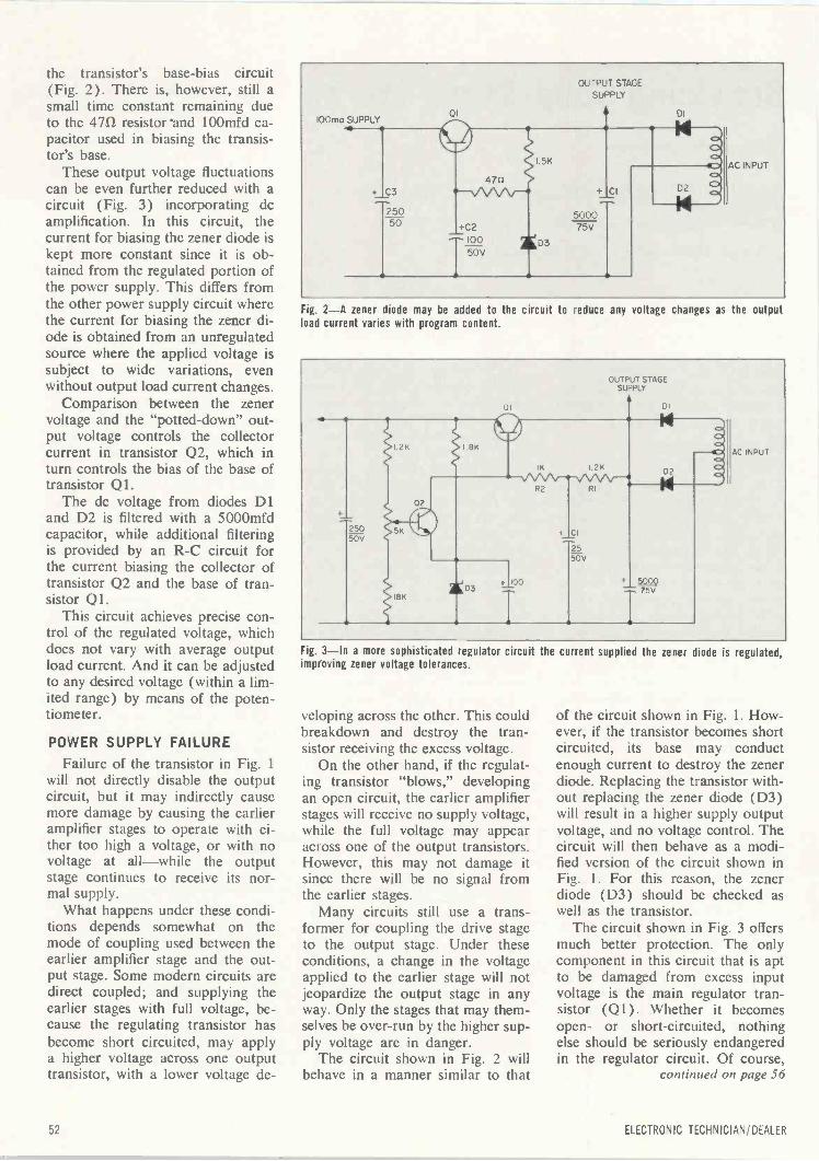
the transistor's base -bias circuit(Fig. 2). There is, however, still asmall time constant remaining dueto the 471/ resistor 100mfd ca-pacitor used in biasing the transis-tor's base.
These output voltage fluctuationscan be even further reduced with acircuit (Fig. 3) incorporating dcamplification. In this circuit, thecurrent for biasing the zener diode iskept more constant since it is ob-tained from the regulated portion ofthe power supply. This differs fromthe other power supply circuit wherethe current for biasing the zener di-ode is obtained from an unregulatedsource where the applied voltage issubject to wide variations, evenwithout output load current changes.
Comparison between the zenervoltage and the "potted -down" out-put voltage controls the collectorcurrent in transistor Q2, which inturn controls the bias of the base oftransistor Ql.
The dc voltage from diodes D1and D2 is filtered with a 5000mfdcapacitor, while additional filteringis provided by an R -C circuit forthe current biasing the collector oftransistor Q2 and the base of tran-sistor Ql.
This circuit achieves precise con-trol of the regulated voltage, whichdoes not vary with average outputload current. And it can be adjustedto any desired voltage (within a lim-ited range) by means of the poten-tiometer.
POWER SUPPLY FAILURE
Failure of the transistor in Fig. 1will not directly disable the outputcircuit, but it may indirectly causemore damage by causing the earlieramplifier stages to operate with ei-ther too high a voltage, or with novoltage at all-while the outputstage continues to receive its nor-mal supply.
What happens under these condi-tions depends somewhat on themode of coupling used between theearlier amplifier stage and the out-put stage. Some modern circuits aredirect coupled; and supplying theearlier stages with full voltage, be-cause the regulating transistor hasbecome short circuited, may applya higher voltage across one outputtransistor, with a lower voltage de-
Fig. 2-A zener diode may be added to the circuit to reduce any voltage changes as the outputload current varies with program content.
Fig. 3-In a more sophisticated regulator circuit the current supplied the zener diode is regulated,improving zener voltage tolerances.
veloping across the other. This couldbreakdown and destroy the tran-sistor receiving the excess voltage.
On the other hand, if the regulat-ing transistor "blows," developingan open circuit, the earlier amplifierstages will receive no supply voltage,while the full voltage may appearacross one of the output transistors.However, this may not damage itsince there will be no signal fromthe earlier stages.
Many circuits still use a trans-former for coupling the drive stageto the output stage. Under theseconditions, a change in the voltageapplied to the earlier stage will notjeopardize the output stage in anyway. Only the stages that may them-selves be over -run by the higher sup-ply voltage are in danger.
The circuit shown in Fig. 2 willbehave in a manner similar to that
of the circuit shown in Fig. 1. How-ever, if the transistor becomes shortcircuited, its base may conductenough current to destroy the zenerdiode. Replacing the transistor with-out replacing the zener diode (D3)will result in a higher supply outputvoltage, and no voltage control. Thecircuit will then behave as a modi-fied version of the circuit shown inFig. 1. For this reason, the zenerdiode (D3) should be checked aswell as the transistor.
The circuit shown in Fig. 3 offersmuch better protection. The onlycomponent in this circuit that is aptto be damaged from excess inputvoltage is the main regulator tran-sistor (Q1). Whether it becomesopen- or short-circuited, nothingelse should be seriously endangeredin the regulator circuit. Of course,
continued on page 56
52 ELECTRONIC TECHNICIAN/DEALER
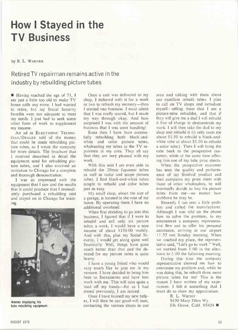
How I Stayed in theTV Business
by R. L. WARNER
Retired TV repairman remains active in the
industry by rebuilding picture tubes
Having reached the age of 71, 1am just a little too old to make TVhouse calls any more. I had wantedto retire, but my Social Securitybenefits were not adequate to meetmy needs. I just had to seek someother form of work to supplementmy income.
An ad in ELECTRONIC TECHNI-CIAN/DEALER told of the moneythat could be made rebuilding pic-ture tubes, so I wrote the companyfor more details. The brochure thatI received described in detail theequipment used for rebuilding pic-ture tubes, and I also received aninvitation to Chicago for a completeand thorough demonstration.
I was so impressed with theequipment that I saw and the resultsthat it could produce that I immedi-ately purchased a rebuilding unitand stayed on in Chicago for train-ing.
Warner displaying histube rebuilding equipment.
Once a unit was delivered to myshop, I tinkered with it for a weekor two to refresh my memory-thenI started into business. I must admitthat I was really scared, but I mademy way through okay. And howsurprised I was with the amount ofbusiness that I was soon handling!
Since then I have been success-fully rebuilding both black -and -white and color picture tubes,wholesaling my tubes to the TV re-pairmen in my area. They all saythat they are very pleased with mywork.
With this unit I am even able torebuild the 20mm Japanese tubesas well as radar and scope picturetubes. I find black -and -white tubessimple to rebuild and color tubesjust as easy.
My small shop, about the size ofa garage, is located in the rear of myhome. By operating there I have noadditional overhead.
When first deciding to go into thisbusiness, I figured that if I were torebuild and sell only six picturetubes a week, I would have a niceincome of about $150.00 weekly.And with this, plus my Social Se-curity, I would get along quite wellfinancially. Well, things have gonemuch better than that and the de-mand for my picture tubes is quiteheavy.
I have a young friend who wouldvery much like to join me in myventure. I have decided to bring himhere to Sacramento and have himwork with me. This will take quite aload off my hands-for as I hadstated previously, I am retired.
Once I have trained my new help-er, I will then be our good -will man,contacting the various shops in our
area and talking with them aboutour excellent rebuilt tubes. I planto call on TV shops and introducemyself-telling them that I am apicture -tube rebuilder, and that ifthey will give me a dud I will rebuildit free of charge to demonstrate mywork. I will then take the dud to myshop and rebuild it (it only costs meabout $1.50 to rebuild a black -and -white tube or about $5.50 to rebuilda color tube). Then I will bring thetube back to the prospective cus-tomer, while at the same time offer-ing him one of my tube price sheets.
When the prospective customerhas seen the quality and perform-ance of my finished product andthen compares my price sheet withthose of other wholesalers, he willeventually decide to buy his picturetubes from me-no matter howstubborn he may be.
Recently I ran into a little prob-lem and called the manufacturer.Although I was told on the phonehow to solve the problem, to myamazement a company representa-tive flew out to offer his personalassistance, arriving at our airport11:55 one Sunday morning. Whenwe reached my place, the represen-tative said, "Let's go to work." Well,we worked from 1:00 in the after-noon to 2:00 the following morning.
During this time the companyrepresentative showed me how toovercome my problem and, while hewas doing this, he rebuilt three morepicture tubes for me! This is thereason I have written of my expe-riences. I felt it something that Imust do to show my appreciation.
R. L. Warner9430 Mary Ellen Wy.Elk Grove, Calif. 95624
AUGUST 1970 53
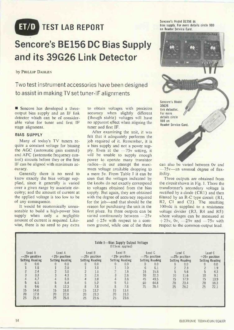
TEST LAB REPORT
Sencore's BE156 DC Bias Supplyand its 39G26 Link Detectorby PHILLIP DAHLEN
Two test instrument accessories have been designed
to assist in making TV set tuner -IF alignments
Sencorc has developed a three -output bias supply and an IF linkdetector which can be of consider-able value for tuner and first IFstage alignment.
BIAS SUPPLY
Many of today's TV tuners re-quire a constant voltage for biasingthe AGC (automatic gain control)and AFC (automatic frequency con-trol) circuits before they or the firstIF can be aligned with maximum ac-curacy.
Generally there is no need toknow exactly the bias voltage sup-plied, since it generally is variedover a given range by associate cir-cuitry; and the amount of current atthe applied voltage is too low to beof any consequence.
It would be economically unrea-sonable to build a high -power biassupply when only a negligibleamount of current is required. Like-wise, there is no need to pay extra
to obtain voltages with precisionaccuracy when slightly different(though stable) voltages will haveno apparent effect when aligning thetuner and first IF.
After examining the unit, it wasfelt that it adequately performs thejob required of it. Remember, it isa bias supply and not a power sup-ply. Even at the -75v setting, itwill be unable to supply enoughpower to operate many transistorradios -in our attempt the maxi-mum voltage available dropping toa mere 5v. From Table I it can beseen that the voltages indicated bythe knobs do not exactly correspondto voltages obtained from the biassupply. But again, they are obtainedwith the degree of accuracy requiredfor the job -and that should be thereason for purchasing the unit in thefirst place. Its three outputs can bevaried continuously between -25vand +25v with respect to a com-mon ground, while one of the three
Sencore's Model BE156 dcbias supply. For more details circle 900on Reader Service Card.
Sencore's Model39G26link detector.For moredetails circle901 onReader Service Card.
can also be varied between Ov and-75v-an unusual degree of flex-ibility.
Three outputs are obtained fromthe circuit shown in Fig. 1. There thetransformer's secondary voltage isrectified by a diode (CR1) and thenfiltered by an R -C type circuit (R1,R2, CI and C2). The resulting100vdc is supplied to a resistancevoltage divider (R3, R4 and R5)where voltages can be measured at+25v, Ov, -25v and -75v withrespect to the common -output lead.
Table I -Bias Supply Output Voltage(115vac applied)
Lead A-25v positionSetting Reading
Lead A. 25v position
Setting Reading
Lead B-25v positionSetting Reading
Lead B25v position
Setting Reading
Lead C-75v position
Setting Reading
Lead C-25v position
Setting Reading
Lead C 25v position
Setting Reading0 0.0 0 0.0 0 0.0 0 0.0 0 0.0 0 0.0 0 0.01 1.6 1 2.0 1 1.0 1 1.0 6 6.1 2 2.3 2 1.92 2.4 2 3.0 2 1.8 2 1.8 15 15.8 5 5.6 5 4.33 3.3 3 4.3 3 2.8 3 2.8 3] 32.3 10 11.6 10 9.1
4 4.7 4 6.0 4 3.8 4 3.8 43 49.5 15 17.9 15 13.95 6.5 5 8.4 5 5.2 5 5.1 60 64.8 20 23.4 20 18.38 9.6 8 12.3 8 7.8 8 7.6 75 78.4 25 28.2 25 22.1
15 14.0 15 18.0 15 13.2 15 13.420 17.8 20 22.8 20 19.3 20 19.325 21.0 25 26.8 25 23.6 25 23.8
ELECTRONIC TECHNICIAN/DEALER
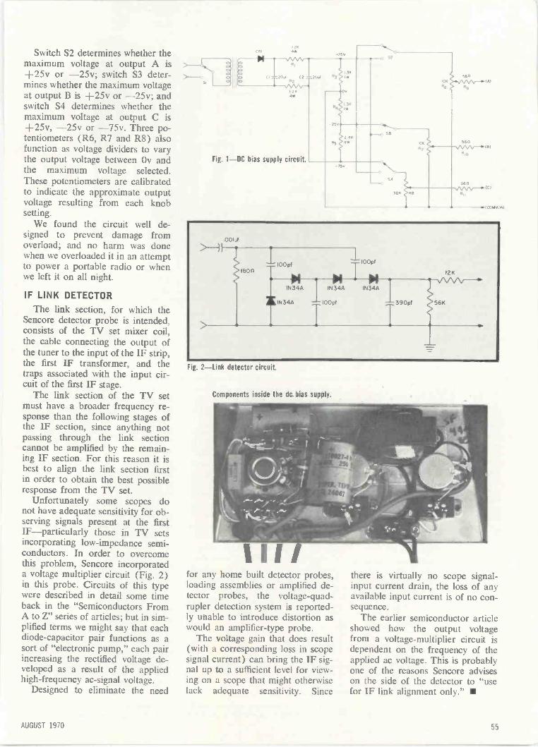
Switch S2 determines whether themaximum voltage at output A is+25v or -25v; switch S3 deter-mines whether the maximum voltageat output B is +25v or -25v; andswitch S4 determines whether themaximum voltage at output C is+25v, -25v or -75v. Three po-tentiometers (R6, R7 and R8) alsofunction as voltage dividers to varythe output voltage between Ov andthe maximum voltage selected.These potentiometers are calibratedto indicate the approximate outputvoltage resulting from each knobsetting.
We found the circuit well de-signed to prevent damage fromoverload; and no harm was donewhen we overloaded it in an attemptto power a portable radio or whenwe left it on all night.
IF LINK DETECTOR
The link section, for which theSencore detector probe is intended,consists of the TV set mixer coil,the cable connecting the output ofthe tuner to the input of the IF strip,the first IF transformer, and thetraps associated with the input cir-cuit of the first IF stage.
The link section of the TV setmust have a broader frequency re-sponse than the following stages ofthe IF section, since anything notpassing through the link sectioncannot be amplified by the remain-ing IF section. For this reason it isbest to align the link section firstin order to obtain the best possibleresponse from the TV set.
Unfortunately some scopes donot have adequate sensitivity for ob-serving signals present at the firstIF-particularly those in TV setsincorporating low -impedance semi-conductors. In order to overcomethis problem, Sencore incorporateda voltage multiplier circuit (Fig. 2)in this probe. Circuits of this typewere described in detail some timeback in the "Semiconductors FromA to Z" series of articles; but in sim-plified terms we might say that eachdiode -capacitor pair functions as asort of "electronic pump," each pairincreasing the rectified voltage de-veloped as a result of the appliedhigh -frequency ac -signal voltage.
Designed to eliminate the need
12Ka*
Fig. 1-DC Jias supply circuit
S2
SS
0560
560
161
18)
ICI
-4.1C08111008)
001,1
Ison100 pf
14 $IN34A IN34A
I0Opf
$IN34A
390pf 56K
I2K
Fig. 2-link datEctor circuit.
Components inside the dc bias supply.
for any home built detector probes,loading assemblies or amplified de-tector probes, the voltage-quad-rupler detection system is reported-ly unable to introduce distortion aswould an amplifier -type probe.
The voltage gain that does result(with a corresponding loss in scopesignal current) can bring the IF sig-nal up to a sufficient level for view-ing on a scope that might otherwiselack adequate sensitivity. Since
there is virtually no scope signal-input current drain, the loss of anyavailable input current is of no con-sequence.
The earlier semiconductor articleshowed how the output voltagefrom a voltage -multiplier circuit isdependent on the frequency of theapplied ac voltage. This is probablyone of the reasons Sencore adviseson the side of the detector to "usefor IF link alignment only."
AUGUST 1970 55

EMERSON 26C56...continued from page 39
circuitry. Horizontal positioning canbe obtained in either direction bycutting the red or blue leads. Theseleads will be found at the rear of thechassis adjacent to the horizontaloutput tube.
To position the picture to theright (as viewed from the front),cut the blue leads; for left position-ing, cut the red leads.
PRODUCTION CHANGES In the brightness control circuit,
R330 has been changed from150K to 120K for increasedbrightness.
In the second chroma amplifiercircuit, R330 has been changedfrom 1K to 390R.
To provide additional protectionagainst internal tube shorts, fuselinks have been added to the fila-ment circuits on PC2 and PC3.The links are of No. 28 solidtinned copper wire with fiber-glass sleeving. On PC2, the fila-ment supply is applied to Pin 6of V204, then through the fusewire to the other heaters on PC2.
HORIZONTALCENTERING DIODES
KINE BIASSWITCH
FOCUSCONTROL
S 0Partial chassis view showing horizontal centering diode and cover removedon HV cage exposing the shielded flyback, shunt regulator and HV rectifier tube.
On PC3, the filament supply hasbeen moved from Pin 5 of V310to Pin 3 of V307. From there itis applied to the other heaters onPC3 through the fuse wire.
The power source is now shown
as 125vac to conform to the newstandard line voltage. A newpower transformer, 730169, isused in place of the 730157transformer used with 120vacline voltage.
SOLID STATE...continued from page 52
the circuits supplied by the regulatedvoltage are subject to the same dan-gers as those supplied by the power -supply circuits shown in Fig. 1 and2.
UNUSUAL VOLTAGE SURGES
So much for faults that occur dur-ing the "normal" operation of asolid-state amplifier system. Anotherfactor to consider is the possibilityof abnormally high supply voltagesresulting from power -line surges ofrelatively short duration.
In any circuit using a zener diodeas a voltage reference, the regulatorcircuit will attempt to hold the volt-age constant, which means that theTO OUTPUT STAGE +
TO OTHER STAGES
THESE ELECTROLYTIC CAPACITORSHAVE VOLTAGE RATINGS ONLYSLIGHTLY HIGHER THAN THEIRWORKING VOLTAGE.
TO OTHER STAGES
TO OUTPUT STAGE
series regulator transistor will be se-riously over -run with excess biasvoltages, and thus much more like-ly to be damaged.
Protecting against such a possi-bility poses certain difficulties. Ifthere is any likelihood of its repeat-ed occurrence, a necessary increasein cost would be justified. But manysolid -state -amplifier systems willnever be exposed to such line volt-age surges. Possibly the most eco-nomical protection is the use ofelectrolytic capacitors rated for onlyslightly more than the normal volt-age - reducing voltage surgesthrough leakage. These capacitorsmust be inserted at the dc voltageoutput of the rectifying diodes (Fig.4) before any series resistors.
The momentary surge current in-to the electrolytic capacitors may
FUSE
LINEINPUT
amount to several amperes-possi-bly more than the normal workingload of the power supply. The rec-tifier diodes may not have a highenough power rating to handle thisexcess current in combination withthe surge voltage. However, it wouldbe less costly for the diodes to bedestroyed by such a surge thanother components exposed to excessdc voltage.
A simple, low-cost component forprotecting the diode is the old-fashioned fuse. By making the elec-trolytic capacitors leak enough cur-rent to blow the fuse before the rec-tifier diodes are destroyed, all thatneeds replacing is an inexpensivefuse.
However, before replacing thefuse it is a sound practice to attemptto determine why the fuse blew.Even though it only blew to provideprotection against over voltage fromthe power line, it is best to checkand make certain that some othercomponent, such as a zener diode ortransistor, was not damaged at thesame time.
Fig. 4-Large electrolytic capacitors and fuses may be used for protecting power supply circuitsagainst short-term line -voltage surges that might otherwise cause serious component damage.
The replacement picture tubeno other color tube
can replace!
MACSin ulated TV picture
Now you can install the revolutionary Chromacolorpicture tube in almost any brand of 23" (diag.) colorTV. And let your customer see the difference: a new,sharper Chromacolor picture with greater brilliance,contrast and color definition.
Zenith pioneered, developed and patented (U.S.Patent No. 3146368) the Chromacolor picture tube.And only Zenith has Chromacolor.
Chromacolor is an easy sale because people al-ready know of Chromacolor's superiority. (Last year,after the revolutionary new Chromacolor system was
TWO-YEAR WARRANTYZenith Radio Corporation warrants the replace-ment CHROMACOLOR picture tube to be freefrom defects in material arising from normalusage for two years from date of original con-sumer purchase. Warranty covers replacementor repair of picture tube, through any authorizedZenith dealer; transportation, labor and servicecharges are the obligation of the owner.
introduced, Zenith giarr-screen color TV sets becamethe No. 1 best-seller!)
Full two-year warranty.Here's your sales clincher: Chromacolor replacementcolor tubes are warranted for two full years. Exactlydouble the warranty period for most other replace-ment color picture tubes.
Give your customers the best - Chromacolor re-placement color tubes. Only your Zenith Distributorhas them.
Zenith Chromacolor picture tubep,npoints the color dots on ajet black background and for thefrrst time fully illuminates every dot.
The qualify goes inbefore the name goes on
AUGUST 1970 57

..without citizenstwo-way radio
Sure as late it's going to hapen -the inevitable inconvenienceon the highway that could turn into a nightmare for someoneclose to you.
Unless, of course, her car is equipped with citizens two-wayradio to close the gap between auto and help instantly whentrouble occurs.
To more than a million American families, citizens two-wayradio already has become not only a marvelous everyday
convenience but a vital and irreplace-able communications link. It can bringa squad car, travel information, a friend-ly voce or a loaf of bread with equalfacility. And for less than the cost of anew set of tires.
ti.,
ELECTRONIC INDUSTRIES ASSOCIATION2001 Eye Stieet, N. W. Washington. D. C. 20006 Citizens Radio Service Sect cn
Can you think of a better way to pro-mote family togetherness or peace ofmind?
58 ELECTRONIC TECHN;CIAN/DEALER
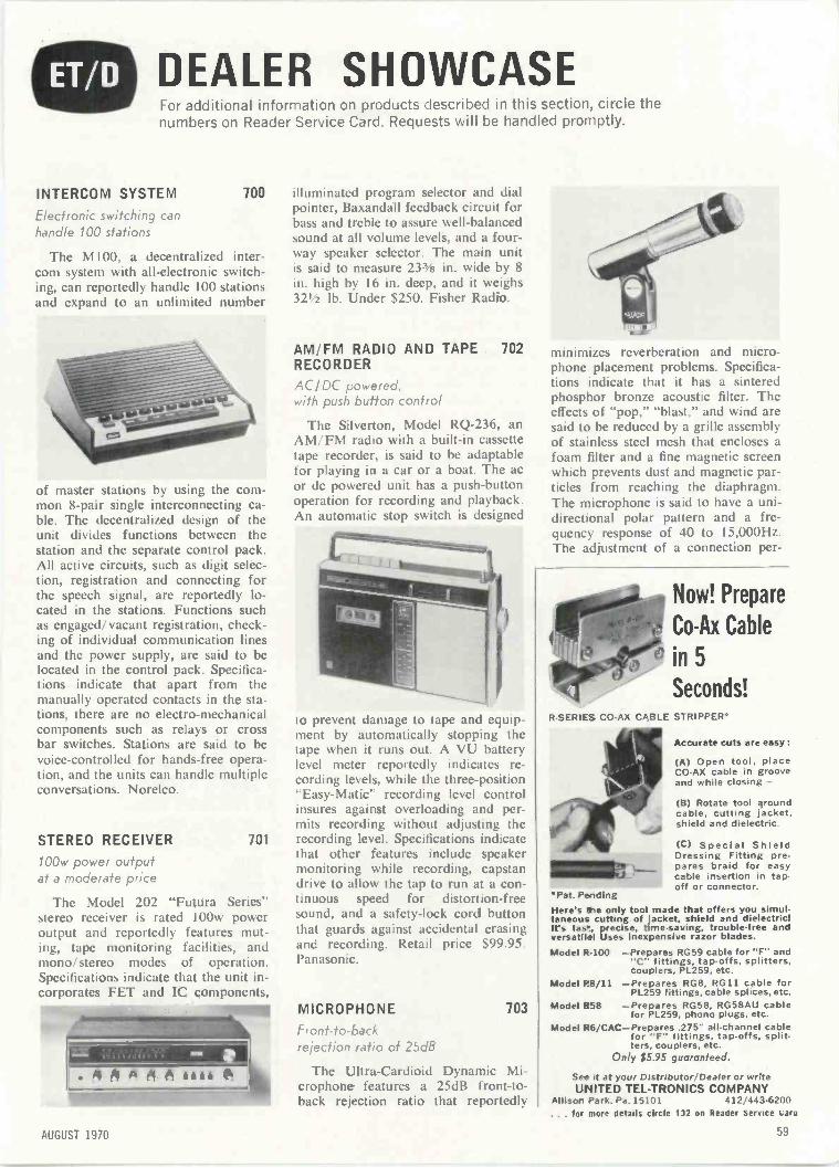
DEALER SHOWCASEFor additional information on products described in this section, circle thenumbers on Reader Service Card Requests will be handled promptly.
INTERCOM SYSTEM 700
Electronic switching canhandle 100 stations
The M100, a decentralized inter-com system with all -electronic switch-ing, can reportedly handle 100 stationsand expand to an unlimited number
of master stations by using the com-mon 8 -pair single interconnecting ca-ble. The decentralized design of theunit divides functions between thestation and the separate control pack.All active circuits, such as digit selec-tion, registration and connecting forthe speech signal, are reportedly lo-cated in the stations. Functions suchas engaged/vacant registration, check-ing of individual communication linesand the power supply, are said to belocated in the control pack. Specifica-tions indicate that apart from themanually operated contacts in the sta-tions, there are no electro-mechanicalcomponents such as relays or crossbar switches. Stations are said to bevoice -controlled for hands -free opera-tion, and the units can handle multipleconversations. Norelco.
STEREO RECEIVER 701
100w power outputat a moderate price
The Model 202 "Futura Series"stereo receiver is rated 100w poweroutput and reportedly features mut-ing, tape monitoring facilities, andmono/ stereo modes of operation.Specifications indicate that the unit in-corporates FET and IC component.
. 4 A
4rmsailt.A A A iiie
illuminated program selector and dialpointer, Baxandall feedback circuit forbass and treble to assure well-balancedsound at all volume levels, and a four-way speaker selector. The main unitis said to measure 233/8 in. wide by 8in. high by 16 in. deep, and it weighs321/2 lb. Under $250. Fisher Radio.
AM/FM RADIO AND TAPE 702RECORDER
AC/DC powerea,with push button control
The Silverton, Model RQ-236, anAM/FM radio with a built-in cassettetape recorder, is said to be adaptablefor playing in a car or a boat. The acor dc powered unit has a push-buttonoperation for recording and playback.An automatic stop switch is designed
to prevent damage to tape and equip-ment by automatically stopping thetape when it runs out. A VU batterylevel meter reportedly indicates re-cording levels, while the three -position"Easy-Matic" recording level controlinsures against overloading and per-mits recording without adjusting therecording level. Specifications indicatethat other features include speakermonitoring while recording, capstandrive to allow the tap to run at a con-tinuous speed for distortion -freesound, and a safety -lock cord buttonthat guards against accidental erasingand recording. Retail price $99.95.Panasonic.
MICROPHONE 703
Front -to -backrejection ratio of 25dB
The Ultra-Cardioid Dynamic Mi-crophone features a 25dB front -to -back rejection ratio that reportedly
minimizes reverberation and micro-phone placement problems. Specifica-tions indicate that it has a sinteredphosphor bronze acoustic filter. Theeffects of "pop," "blast," and wind aresaid to be reduced by a grille assemblyof stainless steel mesh that encloses afoam filter and a fine magnetic screenwhich prevents dust and magnetic par-ticles from reaching the diaphragm.The microphone is said to have a uni-directional polar pattern and a fre-quency response of 40 to I5,000Hz.The adjustment of a connection per -
Now! Prepare
Co -Ax Cable
"' in 5
Seconds!R -SERIES CO -AX CABLE STRIPPER°
Accurate cuts are easy:
(A) Open tool, placeCO -AX cable in grooveand while closing -
(B) Rotate tool aroundcable, cutting jacket,shield and dielectric.
(C) Special ShieldDressing Fitting prepares braid for easycable insertion in tap -off or connector.
Pat. PendingHere's the only tool made that offers you simul-taneous cutting of jacket, shield and dielectric!It's fas-, precise, time -saving, trouble -free andversatile! Uses inexpensive razor blades.
Model R-100 -Prepares RG59 cable for "F" and"C" fittings, tap offs, splitters,couplers, PL259, etc.
Model P8/11 -Prepares RG8, RG11 cable forPL259 fittings, cable splices, etc.
Model R58 -Prepares RG58, RG58AU cablefor PL259, phono plugs, etc.
Model R6/CAC-Prepares .275" all -channel cablefor "F" fittings, tap -offs, split-ters. couplers. etc.
Only $5.95 guaranteed.
See it at your Distributor Dealer or writeUNITED TEL-TRONICS COMPANY
Allisor Park. Pa. 15101 412/443-6200. for more details circle 132 on Reader Service uaro
AUGUST 1970 59
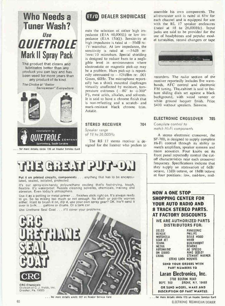
Who Needs a
Tuner Wash?Use
OUIETROLEMark II Spray PackThe product that cleans and
lubricates better than anyproduct you can buy and hasbeen used for more years than
any product of its kind.The Choice of ''Better
Servicemen" Everywhere
nanul,i,ture0 by
.4.QUIETROLE_ COMPANYSpartanburg, South Carolina
... for more details circle 120 on Reader Service Card
DEALER SHOWCASE
mits the selection of either high im-pedance (EIA 40,000(1) or low im-pedance (EIA 15011). Sensitivity athigh impedance is rated at -50dB re:1V/microbar. At low impedance, thesensitivity is rated at -54dB re:lmw/10 microbars. Special shieldingis designed to reduce hum to a negli-gible level in environments whereelectrostatic or magnetic pick-up maybe a problem. Hum pick-up is report-edly attenuated to -121dBm re: .001Gauss, 60Hz. The microphone report-edly has a shock mounted diaphragmvirtually unaffected by moisture, tem-perature extremes (-80° to +300°F), most acids, alkalies, and solvents.It is said to have a chrome finish thatis non-reflecting and a scratch- andmark -resistant black chrome trim.Astatic.
STEREO RECEIVER
Speaker rangeof 18 to 26,000Hz
The RS 17 stereo receiver is de-signed for the listener who prefers to
IAA _PWAWPut it on printed circuits, components . anything that has to be encapsu-lated, sealed, isolated, protected.It's our spray -can -handy polyurethane coating that's fast -drying, tough,flexible. It's waterproof. Resists cleaning solvents. chemicals, marring andabrasion. Even today's atmosphere.Use it as a potting or metal primer ... finishes stick right on, It's always readyto go. So no mixing too much or not enough. No shelf- or pot -life worrieseither. Want to brush it on, dip it, use your own spray gear? OK. We'll send itover in bulk ... gallons or drums. Or a tank car.Use Urethane Seal Coat . . . it'll cover your problems.
CRC ChemicalsDivision of C. J. Webb. Inc.Dresher, Pa. 19025
Ail
assemble his own components. Theall -transistor unit is rated at 65w foreach channel and is equipped for usewith the RL 17 speaker enclosures(rated at 18 to 26,000Hz). Inputjacks are said to be provided for theuse of headphones and popular mod-el turntables, record changers or tape
recorders. The radio section of thereceiver reportedly includes five wave-bands, AFC control and electronicFM tuning. The cabinet is said to fea-ture sliding dials set against a blackbackground, with wood veneer orwhite ground lacquer finish. Price$410 without speakers. Siemens.
ELECTRONIC CROSSOVER 705
704 Complete control tomatch Hi-Fi components
A stereo electronic crossover, theSF -700, is designed to supply completeHi-Fi control through its ability tomatch amplifiers, speaker systems androom acoustics. Four knobs on itsfront panel reportedly control the cut-off characteristics near each crossoverfrequency. Specifications indicate thatthey supply an attenuation of 6dB/octave, 12dB/ octave, or 18dB/ octaveat four positions: low, mid -low, mid -
NOW A ONE STOPSHOPPING CENTER FORYOUR AUTO RADIO AND8 TRACK STEREO PARTS.AT FACTORY DISCOUNTS
WE ARE AUTHORIZED PARTSDISTRIBUTORS FOR:
DELCOBENDIXMOTOROLALEAR JETTENNAMETRAAUTOMATICON GUARDCRAIG
PANASONICPHILIPSBELLE WOODWARD
QUICKMOUNTDEWEKOAC SPEEDOKING SEELEYSTEWART WARNER
STERO LOCK MOUNTS
SEND YOUR ORDERS WITHPART NUMBERS TO
Laran Electronics, Inc.3768 BOSTON ROAD
DEPT 100 BRONX, N.Y. 10469
OR SEND MODEL, MAKE ANDDESCRIPTION OF PART WANTED.
. for more details circle 107 on Reader Service Card
60
. . for more details circle 115 on Reader Service Card
ELECTRONIC TECHNICIAN DEALER
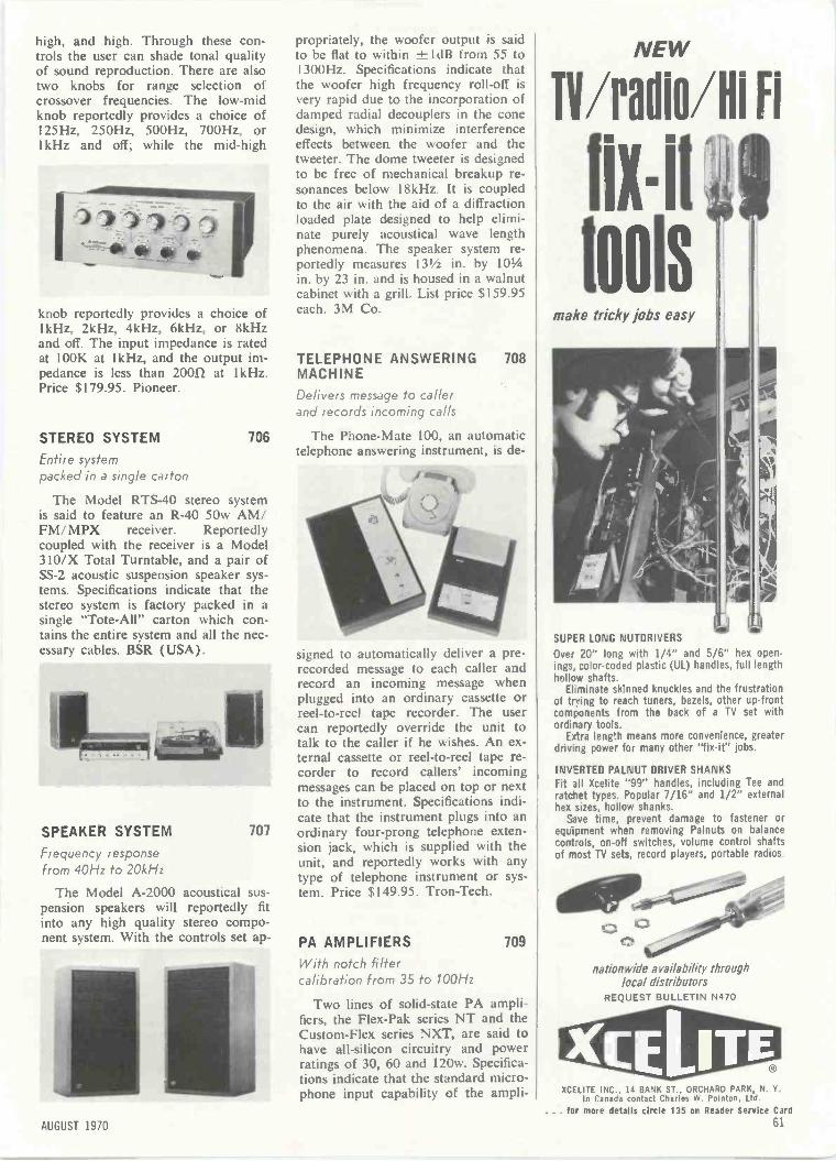
high, and high. Through these con-trols the user can shade tonal qualityof sound reproduction. There are alsotwo knobs for range selection ofcrossover frequencies. The low -midknob reportedly provides a choice of125Hz, 250Hz, 500Hz, 700Hz, or1kHz and off; while the mid -high
knob reportedly provides a choice of1kHz, 2kHz, 4kHz, 6kHz, or 8kHzand off. The input impedance is ratedat 100K at 1 kHz, and the output im-pedance is less than 20011 at I kHz.Price $179.95. Pioneer.
STEREO SYSTEM
Entire systempacked in a single carton
The Model RTS-40 stereo systemis said to feature an R-40 50w AM/FM/MPX receiver. Reportedlycoupled with the receiver is a Model310/X Total Turntable, and a pair ofSS -2 acoustic suspension speaker sys-tems. Specifications indicate that thestereo system is factory packed in asingle "Tote -All" carton which con-tains the entire system and all the nec-essary cables. BSR (USA).
SPEAKER SYSTEM 707
Frequency responsefrom 40Hz to 20kHz
The Model A-2000 acoustical sus-pension speakers will reportedly fitinto any high quality stereo compo-nent system. With the controls set ap-
propriately, the woofer output is saidto be flat to within rtldB from 55 to1300Hz. Specifications indicate thatthe woofer high frequency roll -off isvery rapid due to the incorporation ofdamped radial decouplers in the conedesign, which minimize interferenceeffects between the woofer and thetweeter. The dome tweeter is designedto be free of mechanical breakup re-sonances below 18kHz. It is coupledto the air with the aid of a diffractionloaded plate designed to help elimi-nate purely acoustical wave lengthphenomena. The speaker system re-portedly measures 131/2 in. by 101/4in. by 23 in. and is housed in a walnutcabinet with a grill. List price $159.95each. 3M Co.
TELEPHONE ANSWERING 708MACHINEDelivers message to callerand records incoming calls
706 The Phone -Mate 100, an automatictelephone answering instrument, is de-
signed to automatically deliver a pre-recorded message to each caller andrecord an incoming message whenplugged into an ordinary cassette orreel-to-reel tape recorder. The usercan reportedly override the unit totalk to the caller if he wishes. An ex-ternal cassette or reel-to-reel tape re-corder to record callers' incomingmessages can be placed on top or nextto the instrument. Specifications indi-cate that the instrument plugs into anordinary four -prong telephone exten-sion jack, which is supplied with theunit, and reportedly works with anytype of telephone instrument or sys-tem. Price $149.95. Tron-Tech.
PA AMPLIFIERS 709
With notch filtercalibration from 35 to 100Hz
Two lines of solid-state PA ampli-fiers, the Flex -Pak series NT and theCustom -Flex series NXT, are said tohave all -silicon circuitry and powerratings of 30, 60 and 120w. Specifica-tions indicate that the standard micro-phone input capability of the ampli-
IV/PIO/Hi Fl
IIX-11
toolsmake tricky jobs easy
SUPER LONG NUTDRIVERS
Over 20" long with 1/4" and 5/6" hex open-ings, color -coded plastic (UL) handles, full lengthhallow shafts.
Eliminate skinned knuckles and the frustrationof trying to reach tuners, bezels, other up -frontcomponents from the back of a TV set withordinary tools.
Extra length means more convenience, greaterdriving power for many other "fix -it" jobs.
INVERTED PALNUT DRIVER SHANKSFit all Xcelite "99" handles, including Tee andratchet types. Popular 7/16" and 1/2" externalhex sizes, hollow shanks.
Save time, prevent damage to fastener orequipment when removing Palnuts on balancecontrols, on -off switches, volume control shaftsof most TV sets, record players, portable radios.
nationwide availability throughlocal distributors
REQUEST BULLETIN N470
XCELITE INC., 14 BANK ST., ORCHARD PARK, N. Y.In Canada contact Charles W. Pointon, Ltd.
. for more details circle 135 on Reader Service Card61AUGUST 1970
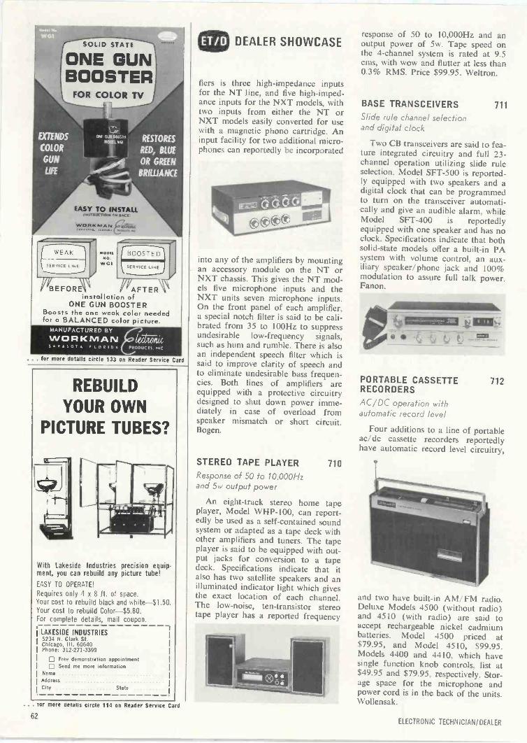
SOLID STATE
ONE GUNBOOSTER
FOR COLOR TV
KW;EXTENDS CIAIMISM RESTORESMOCEL
COLOR RED, BLUEGUN OR GREENLIFE BRIWANCE
7-tri
EASY TO INSTALL,iPaTPLICT10,.. On ACF
WORKMAN
MOORMO
WGI
BEFORE AFTERinstallation of
ONE GUN BOOSTERBoosts the one weak color neededfor a BALANCED color picture.
MANUFACTURED BY
WORKMAN5RASOT FLORID leLVita
PRODUCTS. IPC
. for more details circle 133 on Reader Service Card
REBUILDYOUR OWN
PICTURE TUBES?
With Lakeside Industries precision equipment, you can rebuild any picture tube!
EASY TO OPERATE!
Requires only 4 x 8 ft. of space.Your cost to rebuild black and white $1.50.Your cost to rebuild Color- $5.80.For complete details, mail coupon.
LAKESIDE INDUSTRIES5234 N. Clark St.Chicago, III. 60640Phone: 312.271-3399
Free demonstration appointmentSend me more information
Name
AddressCity State
DEALER SHOWCASE
fiers is three high -impedance inputsfor the NT line, and five high -imped-ance inputs for the NXT models, withtwo inputs from either the NT orNXT models easily converted for usewith a magnetic phono cartridge. Aninput facility for two additional micro-phones can reportedly be incorporated
into any of the amplifiers by mountingan accessory module on the NT orNXT chassis. This gives the NT mod-els five microphone inputs and theNXT units seven microphone inputs.On the front panel of each amplifier,a special notch filter is said to be cali-brated from 35 to 100Hz to suppressundesirable low -frequency signals,such as hum and rumble. There is alsoan independent speech filter which issaid to improve clarity of speech andto eliminate undesirable bass frequen-cies. Both lines of amplifiers areequipped with a protective circuitrydesigned to shut down power imme-diately in case of overload fromspeaker mismatch or short circuit.Bogen.
STEREO TAPE PLAYER 710
Response of 50 to 10,000Hzand 5w output power
An eight -track stereo home tapeplayer, Model WHP-l00, can report-edly be used as a self-contained soundsystem or adapted as a tape deck withother amplifiers and tuners. The tapeplayer is said to be equipped with out-put jacks for conversion to a tapedeck. Specifications indicate that italso has two satellite speakers and anilluminated indicator light which givesthe exact location of each channel.The low -noise, ten -transistor stereotape player has a reported frequency
response of 50 to 10,000Hz and anoutput power of 5w. Tape speed onthe 4 -channel system is rated at 9.5cms, with wow and flutter at less than0.3% RMS. Price $99.95. Weltron.
BASE TRANSCEIVERS 711
Slide rule channel selectionand digital clock
Two CB transceivers are said to fea-ture integrated circuitry and full 23 -channel operation utilizing slide ruleselection. Model SFT-500 is reported-ly equipped with two speakers and adigital clock that can be programmedto turn on the transceiver automati-cally and give an audible alarm, whileModel SFT-400 is reportedlyequipped with one speaker and has noclock. Specifications indicate that bothsolid-state models offer a built-in PAsystem with volume control, an aux-iliary speaker/phone jack and 100%modulation to assure full talk power.Fanon.
s,
PORTABLE CASSETTE 712RECORDERS
AC/DC operation withautomatic record level
Four additions to a line of portableac/dc cassette recorders reportedlyhave automatic record level circuitry,
and two have built-in AM/ FM radio.Deluxe Models 4500 (without radio)and 4510 (with radio) are said toaccept rechargeable nickel cadmiumbatteries. Model 4500 priced at$79.95, and Model 4510, $99.95.Models 4400 and 4410, which havesingle function knob controls, list at$49.95 and $79.95, respectively. Stor-age space for the microphone andpower cord is in the back of the units.Wollensak.
. tor more mails circle 114 on Reader Service Card
62ELECTRONIC TECHNICIAN/DEALER
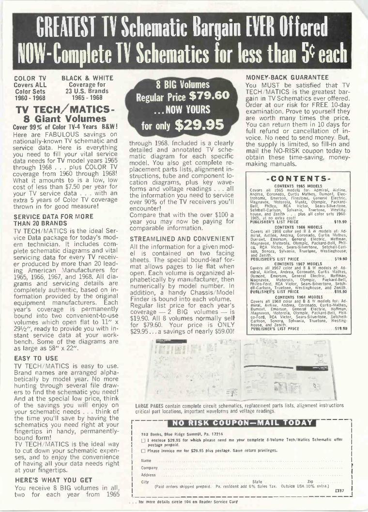
GREATEST TV Schematic Bargain EVER Offered
NOW -Complete TV Schematics for less than SG eachCOLOR TV BLACK & WHITECovers ALL Coverage forColor Sets 23 U.S. Brands1960 - 1968 1965 - 1968
TV TECH/MATICS-8 Giant Volumes
Cover 99 % of Color TV -4 Years B&W !Here are FABULOUS savings onnationally -known TV schematic andservice data. Here is everythingyou need to fill your vital servicedata needs for TV model years 1965through 1968 . . . plus COLOR TVcoverage from 1960 through 1968!What it amounts to is a low, lowcost of less than $7.50 per year foryour TV service data . . . with anextra 5 years of Color TV coveragethrown in for good measure!
SERVICE DATA FOR MORETHAN 20 BRANDSTV TECH MATICS is the ideal Ser-vice Data package for today's mod-ern technician. It includes com-plete schematic diagrams and vitalservicing data for every TV receiv-er produced by more than 20 lead-ing American Manufacturers for1965, 1966, 1967, and 1968. All dia-grams and servicing details arecompletely authentic, based on in-formation provided by the originalequipment manufacturers. Eachyear's coverage is permanentlybound into two convenient -to -usevolumes which open flat to 11" x291/2", ready to provide you with in-stant service data at your work-bench. Some of the diagrams areas large as 58" x 22".
EASY TO USETV TECH; MATICS is easy to use.Brand names are arranged alpha-betically by model year. No morehunting through several file draw-ers to find the schematic you need!And at the special low price, thinkof the savings you will enjoy onyour schematic needs ... think ofthe time you'll save by having theschematics you need right at yourfingertips in handy, permanently -bound form!TV TECH MATICS is the ideal wayto cut down your schematic expen-ses, and to enjoy the convenienceof having all your data needs rightat your fingertips.
HERE'S WHAT YOU GETYou receive 8 BIG volumes in all,two for each year from 1965
8 BIG Volumes
Regular Price $79.60... NOW YOURS
for only $29.95through 1968. Included is a clearlydetailed and annotated TV sche-matic diagram for each specificmodel. You also get complete re-placement parts lists, alignment in-structions, tube and component lo-cation diagrams, plus key wave-forms and voltage readings .. . allthe information you need to serviceover 90% of the TV receivers you'llencounter!Compare that with the over $100 ayear you may now be paying forcomparable information.
STREAMLINED AND CONVENIENTAll the information for a given mod-
sheets. The special bound -leaf for-mat allows pages to lie flat whenopen. Each volume is organized al-phabetically by manufacturer, thennumerically by model number. Inaddition, a handy Chassis ModelFinder is bound into each volume.Regular list price for each year'scoverage - 2 BIG volumes - is$19.90. All 8 volumes ncrmally sellfor $79.60. Your price is ONLY$29.95 ...a savings of nearly $59.00!
r
MONEY -BACK GUARANTEEYou MUST be satisfied that TVTECH 1V1ATICS is the greatest bar-gain it TV Schematics ever offered.Order at our risk for FREE 10 -dayexamination. Prove to yourself theyare worth many times the price.You can return them in 10 days forfull refund or cancellation of in-voice. No need to send money. But,the supply is limited, so fill-in andmail the NO -RISK coupon today toobtain these time -saving, money-making manuals.
-CONTENTS-CONTENTS 1965 MODELS
Covers all 1965 models for: Admiral, Airline.Andrea, Coronado, Curtis Mathes, Dumont, Elec-trohome, Emerson, Firestone, General Electric,Magnavox, Motorola, Muntz, Olympic, Packard -Bell, Philco, RCA Victor, Sears-Silvertone,Setchell-Carlson, Sylvania, Truetone, Westing.house, and Zenith . . . plus all color sets 1960-1965, at no extra cost!PUBLISHER'S LIST PRICE $19.90
CONTENTS 1966 MODELSCovers all 1966 color and B & W models of: Ad-mi-al, Airline, Andrea, Coronado, Curtis Mathes,Dumont, Emerson, General Electric, Hoffman,Magnavox, Motorola, Olympic, Packard -Bell, Phil -co, RCA Victor, Sears-Silvertone, Setchell-Carl-scn, Sonora, Sylvania, Truetone, Westinghouse.and Zenith.PUBLISHER'S LIST PRICE $19.90
CONTENTS 1967 MODELSCovers all 1967 color and B & W models of: Ad-miral, Airline, Andrea, Coronado, Curtis Mathes,Dumont, Emerson, General Electric, Hoffman.Magnavox, Motorola, Olympic, Packard -Bell.Philco-Ford, RCA Victor, Sears-Silvertone, Setch-ell-Carlson, Truetone, Westinghouse, and Zenith.PUBLISHER'S LIST PRICE $19.90
CONTENTS 1968 MODELSCovers all 1968 color and B & W models for: Ad-miral, Airline, Andrea, Coronado, Curtis -Mathes,Dumont, Emerson, General Electric, Hoffman,Magnavox, Motorola, Olympic, Packard -Bell, Phil -co -Ford, RCA Victor, Sears-Silvertone, Setchell.Carlson, Sonora, Sylvania, Truetone, Westing-house, and Zenith.PUBLISHER'S LIST PRICE $19.90
LARGE PAGES contain complete circuit schematics, replacement parts lists, alignment instructionscritical part locations, important waveforms and vcltage readings.
NO RISK COUPON-MAIL ODAYTA3 Books, Blue Ridge Summit, Pa. 17214 I enclose $29.95 for which please send me yokr complete 8 -Volume Tech, Matics Schematic offer
postage prepaid. Please invoice me for $29.95 plus postage. Same return privileges.
State Zip(Paid orders shipped prepaid. Pa. resident add 6% Sales Tax. Outside USA 10% extra.)
ET87
. . . fcr more details circle 104 on Reader Service Card
Name
Company
Address
City
NEWS
OF THE INDUSTRY
Electronic Industry Show Corp.Elects New Directors
Exhibitors at the highly successful NEW Show climaxedtheir activities by electing a new slate to the Board of Di-rectors of Electronic Industry Show Corp. The electionwas the first under a new set of by-laws calling for the ex-hibitors to elect directors rather than the sponsoring tradeassociations to appoint members of the Board. Of thethirteen directors elected, nine are incumbents, three havepreviously served on the board, and one-Vincent Hook-is a newcomer. ti
Hook, executive vice-president and general manager ofC & G Electronics Company, Tacoma, Wash., is a pastpresident and director of the Northwest Chapter of theNational Electronic Distributors Assn., and has served aspresident and director of Electronic Distributors ResearchInstitute.
Returning to the Show Board are James L. Nichols, pres-ident of Mallory Distributor Products; Edward M. Rothen-stein, executive vice-president of Philmore Manufacturing;and Arthur I. Rabb, president, United Technical Publica-tions.
Incumbents reelected to the Board include James S. Sil-verman, Electronic Expeditors; Robert C. Trinkle, TrinkleSales, Inc.; John N. Leedom, Wholesale Electronics Sup-ply; James C. Neustadt, Burstein-Applebee; Glenn E.Ronk, Sola Electric; Clyde J. Schultz, Switchcraft; PhilipE. Gustafson, Hughes -Peters; Robert B. Morris, SpecialtyDistributing, and Roy Vetzner, Vaco Products.
Hereafter all directors will be elected for three-yearterms, with one-third retiring each year. The new Boardof Directors will meet in August in California to makeplans for the 1971 NEW Show, scheduled to be held theweek of June 1 in Bal Harbour, Fla.
Consumer Protection Planfor Zenith Color TV Purchasers
Zenith Radio Corp. announced a new "consumer pro-tection plan" for purchasers of the company's color TVsets, starting with the 1971 line of models. The major ob-jective of the plan is to assure that in -warranty service isperformed at no cost to the consumer for parts or laborduring the first 90 days of set ownership. The plan, in-cluding its warranty provisions, offers:
Service labor required during the 90 -day warrantyperiod will be performed without charge to the setowner, and replacement of any parts required duringthe warranty period will be performed without chargeto the set owner.
Replacement of a color TV picture tube that becomesdefective within two years of the color set's originalconsumer purchase will be made without charge forthe tube.
Replacement or repair of any other parts that be-come defective within one year of the set's initialinstallation will be made without charge for the com-ponents.
Under the plan, 90 -day in -home service is provided atno charge for consoles and large screen table models, 20 -in diagonal and larger. Portable and Compact Table Modelreceivers (14- through 19 -in. diagonal screen sizes)brought into the dealer or his servicing contractor by the
owner will be serviced at no cost during the first 90 daysof set ownership.
An integral part of Zenith's plan is the provision for in -warranty service through the local Zenith dealer, wherethe set was purchased, or his independent servicing con-tractor.
"Strengthening the dealer's after -sale responsibility forthe product is the key element which can make the mostimportant single contribution to efficient and responsibleservice in any warranty program," said W. C. Fisher, presi-dent of the Zenith Sales Co. division.
U.S. Consumer Electronic SalesFigures tot First Quarter of 1970
Total U.S. sales of consumer electronic products, includ-ing imports, have been released by the Electronic Indus-tries Assn.'s Marketing Services Dept. The EIA report re-flects the size of the U.S. market in units for monochromeand color TV sets, radios, tape recorders and players forthe first three months of 1970, along with comparisonsfor the same period in 1969.
Total TV sales in the first quarter reached 2,652,479sets in 1970 vs. 3,363,678 sets in 1969, down 21.1%.Color TV's share reached 1,160,419 sets. Some 1.8 mil-lion sets of first-quarter sales were produced in this coun-try. U.S. manufacturers also imported some 429,000 setsfor merchandising under their own labels; foreign -labelTV sets amounted to some 421,424 units, or about 15%of the total TV market.
The total home radio market in the first quarter (ex-cluding TV and photograph combinations and auto radios)amounted to 7.6 million units compared to 8.3 millionunits in the same period in 1969. U.S. manufacturers pro-duced 0.6 million units and imported 1.3 million units forsale under their own labels. Foreign labels, with 5.7 mil-lion radios imported, accounted for 75% of the sales vs.67% in the first quarter of 1969.
Total U.S. sales of auto radios in the first quarter at 2.8million units matched the 3.3 million units sold in thesame 1969 period.
The FM share of radio sales continued to increase. Some5.0 million radios were sold in the first quarter as com-pared to 4.1 million in the same period in 1969. Home ra-dio sales share (excluding radio -TV -phonograph combi-nations) jumped to some 60% compared to about 44%in the same period in 1969 and only 40% in the first quar-ter of 1968.
Total U.S. phonograph sales in the first quarter totaled1.1 million units compared to 1.5 million in the sameperiod in 1969.
Magnetic tape continued to be the fastest growing con-sumer electronic product in the first quarter. Tape record-ers, including reel-to-reel and cassette equipment, totaled1.6 million units compared to 1.2 million in the same 1969period. Tape player imports totaled 1.4 million units com-pared to only 801,000 units in the 1969 first quarter. U.S.product figures in this category are not available.
Magnavox Introduces HomeStudy Color TV Service Course
Magnavox has announced a home -study color TV ser-vice course. Entitled "Color TV . . . An Introduction toServicing," the 16 -lesson course is designed to provide thebasic training for persons considering TV service as a vo-cation.
Magnavox National Service Manager Ray Yeranko ex-plains that this training program is unique because stu-dents must be sponsored by a servicing dealer or service
64 ELECTRONIC TECHNICIAN/DEALER
contractor and be given access to shop facilities, equip-ment and Magnavox products in order to carry out spe-cific lesson assignments. In this way, each student is giventhe opportunity to become familiar with Magnavox ColorTV service procedures as he studies his lesson materials.
Lesson quizzes must be completed and sent to Magnavoxfor grading by its Service Training Department. After thestudent completes the course at a pace he has established,he is presented with a certificate qualifying him for ad-vanced studies at any one of the seven Magnavox ServiceTraining Centers.
It is expected that dealers who have been hard pressedfor more qualified service technicians will include in theirrecruitment plans the hiring of young men from their localhigh schools as part-time employees. Such men taking theMagnavox home study course could, after a reasonabletime, relieve the employer's more experienced techniciansof less complex servicing assignments. Further infor-mation can be obtained from the Service Training Dept.,1700 Magnavox Way, Fort Wayne, Indiana 46804.
ICS Announces NewFCC License Course
International Correspondence Schools (ICS), a divisionof INTEXT, Scranton, Pa., has announced the release ofa new FCC license course: The Commercial Radiotele-phone License Course. Students can enroll either in oneor more divisions of the course or in the whole course.
Division 1 is relatively short and covers preparation forthe Third Class Radiotelephone License, with or withoutBroadcast Endorsement (FCC Elements 1, 2, and 9). Anoptional section of Division 1 is preparation for the Ra-dio Amateur Novice License.
Division 2 covers FCC Element 3, for the FCC SecondClass Radiotelephone License examination.
Division 3 covers preparation for the FCC First ClassRadiotelephone License (Element 4). A separate text alsocovers study for the Radar endorsement. The course iscovered by the ICS Double Warranty.
All three divisions include self -check review examswhich permit the student or trainee to test his own knowl-edge with FCC -style questions-answers are providedseparately as a guide to technical or specialized areas.
Study material and texts have been written by such wellknown experts in the communications -broadcasting field asDr. Charles R. Ammerman, Thomas R. Haskett, CharlesT. Morgan, Edward M. Noll, William Ornstein, and Leo G.Sands. Further information can be obtained by contactingJoseph Risse, ICS, Scranton, Pa. 18515.
GC
"What shjuld I wear today?"
no otherneat gun...
offersall theseattachments!Attachments to speed your job ...attachments that tailor Master heatgun airflow precisely to your needs... attachments that fit any existingMaster flameless heat gun. No otherline offers so many choices ...including the exclusive patentedcone for 1/4 " concentrated heat, optionaladjustable base, convenient carryingcase, and the only U.L. listed gunavailable. Send for free 12 page catalog.
MASTERRacine, WI 53403
For shrinking
thermoplastictubing and film,curing, Forming,
melting, drying,soldering.
. . . 'or more details circle 117 on Reader Service Card
AUGUST 1970 65
An Extraordinary Offerto introduce you to the benefits of Membership in
ELECTRONICS BOOK CLUB
ANYfor a limited time only you can obtain
OFTHESEUNIQUEBOOKS ...with Trial
(Combined List Price $23.85) Club Membership 9. yours for only 0
May we send you your choice ofany three books on the facing
page as part of an unusual offer of aTrial Membership in Electronics BookClub?
Here are quality hardbound vol-umes, each especially designed to helpyou increase your know-how, earningpower, and enjoyment of electronics.
These handsome, hardbound booksare indicative of the many other fineofferings made to Members .. . impor-tant books to read and keep . . . vol-umes with your specialized interests inmind.
Whatever your interest in electron-ics -radio and TV servicing, audio andhi-fi, industrial electronics, communi-cations, engineering -you will findthat Electronics Book Club will helpyou.
With the Club providing you withtop quality books, you may broadenyour knowledge and skills to buildyour income and increase your under-standing of electronics, too.
How You Profit From Club Membership
This special offer is just a sample ofthe help and generous savings theClub offers you. For here is a Club de-voted exclusively to seeking out onlythose titles of direct interest to you.Membership in the Club offers youseveral advantages.1. Charter Bonus: Take any three ofthe books shown (combined values upto $23.85) for only 990 each with yourTrial Membership.2. Guaranteed Savings: The Clubguarantees to save you 15% to 75%on all books offered.3. Continuing Bonus: If you continueafter this trial Membership, you willearn a Dividend Certificate for everybook you purchase. Three Certificates,plus payment of the nominal sum of$1.99, will entitle you to a valuableBook Dividend which you may choosefrom a special list provided members.
4. Wide Selection: Members are an-nually offered over 50 authoritativebooks on all phases of electronics.
5. Prevents You From Missing NewBooks: The Club's FREE monthlyNews gives you advance notice of im-portant new books . . . books vital toyour continued advancement.
This extraordinary offer is intendedto prove to you, through your own ex-perience, that these very real advan-tages can be yours . . . that it is pos-sible to keep up with the literaturepublished in your areas of interest ...and to save substantially while so do-ing.
How the Club Works
Forthcoming selections are describedin the FREE monthly Club News.Thus, you are among the first to knowabout, and to own if you desire, sig-nificant new books. You choose onlythe main or alternate selection youwant (or advise if you wish no bookat all) by means of a handy form andreturn envelope enclosed with theNews. As part of your Trial Member-ship, you need purchase as few as fourbooks during the coming 12 months.You would probably buy at least thismany anyway . . . without the sub-stantial savings offered through ClubMembership.
Limited Time Offer!
Here, then, is an interesting oppor-tunity to enroll on a trial basis . . . toprove to yourself, in a short time, theadvantages of belonging to Electron-ics Book Club. We urge you, if thisunique offer is appealing, to actpromptly, for we've reserved only alimited number of books for new Mem-bers.
To start your Membership on theseattractive terms, simply fill out andmail the postage -paid airmail card to-day. You will receive the three booksof your choice for 10 -day inspection.SEND NO MONEY! If you are notdelighted, return them within 10 days
and your Trial Membership will becancelled without cost or obligation.Electronics Book Club, Blue RidgeSummit, Pa. 17214.
Typical Savings Offered ClubMembers on Recent Selections
How to Repair Home & AutoAir Conditioners
List Price $7.95; Club Price $4.95How to Repair Solid -State Imports
List Price $7.95; Club Price $3.95Handbook of Magnetic Recording
List Price $7.95; Club Price $4.95Nag Color TY Service Manual
List Price $7.95; Club Price $4.95Am Radio Advanced Class
Study GuideList Price $6.95; Club Price $3.95
Servicing Modern Hi-Fi/Stereo SystemsList Price $7.95; Club Price $4.95
Electronic CircuitsList Price $11.95; Club Price $8.95
Dictionary of ElectronicsList Price $6.95; Club Price $5.50
CATY System EngineeringList Price $12.95; Club Price $7.95
Solid State Circuit Design & OperationList Price $9.95; Club Price $5.95
How to Build a Working DigitalComputer
List Price $7.95; Club Price $3.95Zenith Color TV Service Manual
List Price $7.95; Club Price $4.95Servicing Electronic Organs
List Price $7.95; Club Price $4.95Digital Computer Analysis
List Price $10.95; Club Price $7.95How To Test Almost Everything Electronic
List Price $5.65; Club Price $3.95How to Use Your YOM, YTYM & Scope
List Price $6.95; Club Price $4.95Radio Operator's Q & A Manual
List Price $8.95; Club Price $7.50Tape Recording For Fun & Profit
List Price $7.95; Club Price $4.95Elements of Tape Recorder Circuits
List Price $7.95; Club Price $3.95Industrial Electronics Made Easy
List Price $8.95; Club Price $5.95Electronic Test & Measurement Handbook
List Price $7.95; Club Price $4.95Easy Way To Service Radios
List Price $6.95; Club Price $3.95Practical Color TV Servicing Techniques
List Price $8.95; Club Price $5.95Mathematics for Electronics
List Price $10.95; Club Price $7.95Transistor Projects
List Price $5.95; Club Price $2.95Electronic Musical Instruments
List Price $10.00; Club Price $7.95
AM EXTRAORDINARY OFFER...ELECTRONIC TECHNICIAN/DEALER
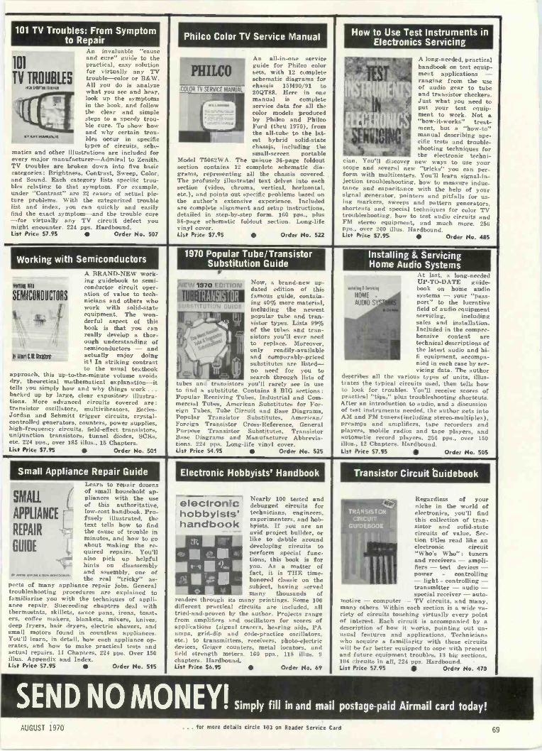
101 TV Troubles: From Symptomto Repair Philco Color TV Service Manual How to Use Test Instruments in
Electronics Servicing
101
TV TROUBLES1111151101111 5
BY API MAISIGOOS
An invaluable "causeand cure" guide to thepractical, easy solutionfor virtually any TVtrouble --color or B&W.All you do is analyzewhat you see and hear,look up the symptomsin the book, and followthe clear and simplesteps to a speedy trou-ble cure. To show howand why certain trou-bles occur in specifictypes of circuits, sche-
matics and other illustrations are included forevery major manufacturer-Admiral to Zenith.TV troubles are broken down into five basiccategories: Brightness, Contrast, Sweep, Color.and Sound. Each category lists specific trou-bles relating to that symptom. For example.under "Contrast" are 22 causes of actual pic-ture problems. With the categorized troublelist and index, you can quickly and easilyfind the exact symptom-and the trouble cure-for virtually any TV circuit defect youmight encounter. 224 pps. Hardbound.List Price $7.95 Order No. 507
Working with Semiconductors
SEMICONDUCTORS
Nall1L11811101
A BRAND-NEW work-ing guidebook to semi-conductor circuit oper-ation of value to tech-nicians and others whowork with solid-stateequipment. The won-derful aspect of thisbook is that you canreally develop a thor-ough understanding ofsemiconductors - andactually enjoy doingit! In striking contrastto the usual textbook
approach, this up-to-the-minute volume avoidsdry, theoretical mathematical explanation --ittells you simply how and why things work ...backed up by large, clear expository illustra-tions. More advanced circuits covered are:transistor oscillators, multivibrators, Eccles -Jordan and Schmitt trigger circuits, crystal -controlled generators, counters, power supplies,high -frequency circuits, field-effect transistors.unijunction transistors, tunnel diodes, SCRs,etc. 224 pps., over 185 illus., 15 Chapters.List Price 57.95 Order No. 501
PHILCOAn all -in -one serviceguide for Philco colorsets, with 12 completeschematic diagrams forchassis 15M90/91 to20QT88. Here in one
1111j
manual is complete
color models produced
hybrid solid-state
service data for all the
by Philco and Phil.-Ford ithru 19701. frotthe all -tube to the lat-estchassis,
including thesmall -screen portable
Model T5062WA. The unique 36 -page foldoutsection contains 12 complete schematic dia-grams, representing all the chassis covered.The profusely illustrated text delves into eachsection i video, chrome, vertical, horizontal,etc.), and points out specific problems based onthe author's extensive experience. Includedare complete alignment and setup instructions,detailed in step-by-step form. 160 pps., plus36 -page schematic foldout section. Long -lifevinyl cover.List Price $7.95 Order No. 522
A lung -needed, practicalhandbook on test equip-ment applications -ranging from the useof audio gear to tubeand transistor checkers.Just what you need toput your test equip-ment to work. Not a"how -it -works" treat-ment, but a "how-to"manual describing spe-cific tests and trouble-shooting techniques forthe electronic techni-
cian. You'll discover new ways to use yourscope and several new "tricks" you can per-form with multitesters. You'll learn signal -in-jection troubleshooting, how to measure induc-tance and capacitance with the help of yoursignal generator, pointers and pitfalls for us-ing markers, sweeps and pattern generators.shortcuts and special techniques for color TVtroubleshooting. how to test audio circuits andFM stereo equipment, and much more. 256pus over 200 illus. Hardbound.List Price $7.95 Order No. 485
1970 Popular Tube/TransistorSubstitution Guide
1570 -stTlrIN Now, a brand-new up-dated edition of thisfamous guide, contain-ing 405 more material,including the newestpopular tube and tran-sistor types. Lists 990of the tubes and tran-sistors you'll ever needto replace. Moreover,only readily -availableand comparably -pricedsubstitutes are listed-no need for you tosearch through lists of
tubes and transistors you'll rarely see in useto find a substitute. Contains 8 BIG sections:Popular Receiving Tubes, Industrial and Com-mercial Tubes. American Substitutes for For-eign Tubes, Tube Circuit and Base Diagrams,Popular Transistor Substitutes, American/Foreign Transistor Cross -Reference, GeneralPurpose Transistor Substitutes, TransistorBase Diagrams and Manufacturer Abbrevia-tions. 224 pps. Long -life vinyl cover.List Price 54.95 Order No. 525
Installing & ServicingHome Audio Systems
At last, a long -neededUP-TO-DATE guide -
Waal !Wm book on home audioHOME . systems - your "pass-AU010 port" to the lucrative
field of audio equipmentservicing, includingsales and installation.Included in the compre-hensive content aretechnical descriptions ofthe latest audio and hi-ll equipment, accompa-nied in each case by ser-vicing data. The author
describes all the various types of units, illus-trates the typical circuits used, then tells howto look for troubles. You'll receive scores ofpractical "tips," plus troubleshooting shortcuts.After an introduction to audio, and a discussionof test instruments needed, the author gets intoAM and FM tonersi including stereo -multiplex),preamps and amplifiers, tape recorders andplayers, mobile radios and tape players, andautomatic record players. 256 pps., over 150illus., 12 Chapters. Hardbound.List Price $7.95 Order No. 505
Small Appliance Repair Guide
SMALL
APPLIANCE r -
REPAIR tGUIDE
INATO 011os 4.00drOa1,
Learn to repair dozensof small household ap-pliances with the useof this authoritative,low-cost handbook. Pro-fusely illustrated, thetext tells how to findthe cause of trouble inminutes, and how to goabout making the re-quired repairs. You'llalso pick up helpfulhints on disassemblyand assembly, one ofthe real "tricky" as-
pects of many appliance repair jobs. Generaltroubleshooting procedures are explained tofamiliarize you with the techniques of appli-ance repair. Succeeding chapters deal withthermostats, skillets, sauce pans, irons, toast-ers, coffee makers, blankets, mixers, knives,deep fryers, hair dryers, electric shavers, andsmall motors found in countless appliances.You'll learn, in detail, how each appliance op-erates, and how to make practical tests andactual repairs. 11 Chapters, 224 pps. Over 150illus. Appendix and Index.List Price $7.95 Order No. 515
Electronic Hobbyists' Handbook
electronichobbyists'handbook
Nearly 100 tested anddebugged circuits fortechnicians, engineers,experimenters, and hob-byists. If you are anavid project builder, orlike to dabble arounddeveloping circuits toperform special func-tions, this book is foryou. As a matter offact, it is THE time-honored classic on thesubject, having servedmany thousands of
readers through its many printings. Some 100different practical circuits are included, alltried -and -proven by the author. Projects rangefrom amplifiers and oscillators for scores ofapplications I signal tracers, hearing aids, PAamps, grid -dip and code -practice oscillators.etc.1 to transmitters, receivers, photo -electricdevices, Geiger counters, metal locators, andfield strength meters. 160 pps., 118 illus. 9chapters. Hardbound.List Price $6.95 Order No. 69
in "Tr'
"A fit 111
Tip II
0 ?",4
Transistor Circuit Guidebook
Regardless of yourniche in the world ofelectronics, you'll findthis collection of tran-sistor and solid-statecircuits of value. Sec-tion titles read like anelectronic circuit"Who's Who": tunersand receivers - ampli-fiers - test devices -power - controlling- light - controlling -transmitter - audio -special receiver - auto-
motive - computer - TV circuits, and many,many others Within each section is a wide va-riety of circuits touching virtually every pointof interest. Each circuit is accompanied by adescription of how it works, pointing out un-usual features and applications. Technicianswho acquire a familiarity with these circuitswill be far better equipped to cope with presentand future equipment troubles. 13 big sections,104 circuits in all, 224 pps. Hardbound.List Price $7.95 Order No. 470
TRANSISTORCIRCUIT
GU'OE13001
SEND NO MONEY! Simply fill in and mail postage -paid Airmail card today!
AUGUST 1970 . for more details circle 103 on Reader Service Card 69
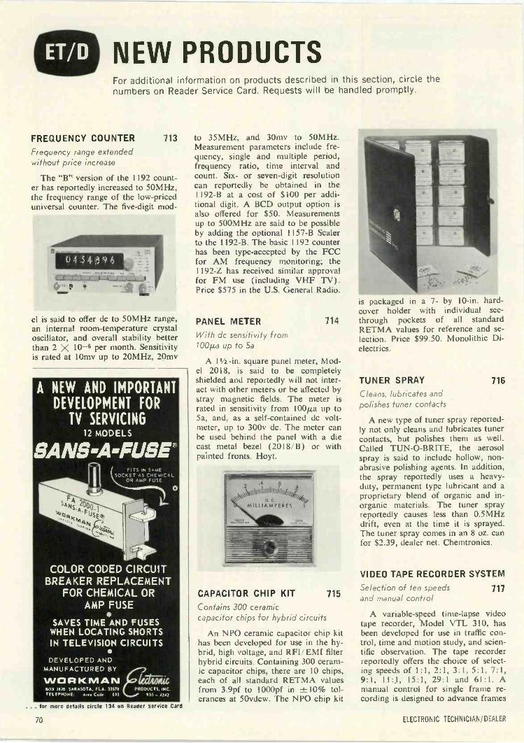
NEW PRODUCTSFor additional information on products described in this section, circle thenumbers on Reader Service Card. Requests will be handled promptly.
FREQUENCY COUNTER 713
Frequency range extendedwithout price increase
The "B" version of the 1192 count-er has reportedly increased to 50MHz,the frequency range of the low-priceduniversal counter. The five -digit mod-
el is said to offer dc to 50MHz range,an internal room -temperature crystaloscillator, and overall stability betterthan 2 X 10⁻⁶ per month. Sensitivityis rated at 10mv up to 20MHz, 20mv
A NEW AND IMPORTANTDEVELOPMENT FOR
TV SERVICING12 MODELS
SANS -A -FUSE®FITS IN SAME
SOCKET AS CHEMICALOR AMP FUSE
O
COLOR CODED CIRCUITBREAKER REPLACEMENT
FOR CHEMICAL ORAMP FUSE
SAVES TIME AND FUSESWHEN LOCATING SHORTSIN TELEVISION CIRCUITS
DEVELOPED ANDMANUFACTURED BY
WORKMANBOX 3838 SARASOTA FLA 3357$ PRODUCTS INCTELEPHONE Atee Code 813 9Ss 4147
... for more details circle 134 on Reader Service Card
to 35MHz, and 30mv to 50MHz.Measurement parameters include fre-quency, single and multiple period,frequency ratio, time interval andcount. Six- or seven -digit resolutioncan reportedly be obtained in the1192-B at a cost of $100 per addi-tional digit. A BCD output option isalso offered for $50. Measurementsup to 500MHz are said to be possibleby adding the optional 1157-B Scalerto the 1192-B. The basic 1192 counterhas been type -accepted by the FCCfor AM frequency monitoring; the1192-Z has received similar approvalfor FM use (including VHF TV).Price $575 in the U.S. General Radio.
PANEL METER
With dc sensitivity from100µa up to 5a
is packaged in a 7- by 10 -in. hard-cover holder with individual see -
714 through pockets of all standardRETMA values for reference and se-lection. Price $99.50. Monolithic Di-electrics.
A 11/2 -in. square panel meter, Mod-el 2018, is said to be completelyshielded and reportedly will not inter-act with other meters or be affected bystray magnetic fields. The meter israted in sensitivity from 100p.a up to5a, and, as a self-contained dc volt-meter, up to 300v dc. The meter canbe used behind the panel with a diecast metal bezel (2018/B) or withpainted fronts. Hoyt.
2 '41
\VV\111,11ifiltillilkiil
MILLIAMPERES 1
CAPACITOR CHIP KIT 715
Contains 300 ceramiccapacitor chips for hybrid circuits
An NPO ceramic capacitor chip kithas been developed for use in the hy-brid, high voltage, and RFI!EMI filterhybrid circuits. Containing 300 ceram-ic capacitor chips, there are 10 chips,each of all standard RETMA valuesfrom 3.9pf to 1000pf in -1=10% tol-erances at 50vdcw. The NPO chip kit
TUNER SPRAY 716
Cleans, lubricates andpolishes tuner contacts
A new type of tuner spray reported-ly not only cleans and lubricates tunercontacts, but polishes them as well.Called TUN-O-BRITE, the aerosolspray is said to include hollow, non-abrasive polishing agents. In addition,the spray reportedly uses a heavy-duty, permanent type lubricant and aproprietary blend of organic and in-organic materials. The tuner sprayreportedly causes less than 0.5MHzdrift, even at the time it is sprayed.The tuner spray comes in an 8 oz. canfor $2.39, dealer net. Chemtronics.
VIDEO TAPE RECORDER SYSTEM
Selection of ten speedsand manual control
717
A variable -speed time-lapse videotape recorder, Model VTL 310, hasbeen developed for use in traffic con-trol, time and motion study, and scien-tific observation. The tape recorderreportedly offers the choice of select-ing speeds of 1:1, 2:1, 3:1, 5:1, 7:1,9:1, 11:1, 15:1, 29:1 and 61:1. Amanual control for single frame re-cording is designed to advance frames
70 ELECTRONIC TECHNICIAN/DEALER
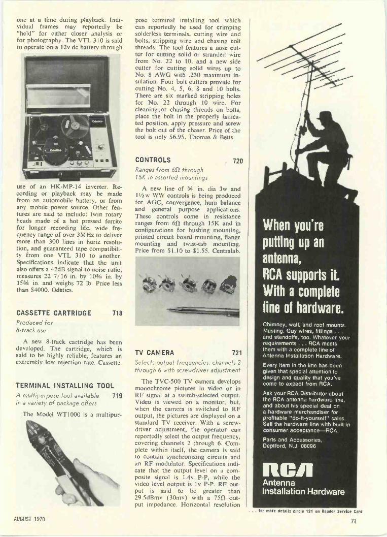
one at a time during playback. Indi-vidual frames may reportedly be"held" for either closer analysis orfor photography. The VTL 310 is saidto operate on a 12v dc battery through
use of an HK -MP -14 inverter. Re-cording or playback may be madefrom an automobile battery, or fromany mobile power source. Other fea-tures are said to include: twin rotaryheads made of a hot pressed ferritefor longer recording life, wide fre-quency range of over 3MHz to delivermore than 300 lines in horiz resolu-tion, and guaranteed tape compatibili-ty from one VTL 310 to another.Specifications indicate that the unitalso offers a 42dB signal-to-noise ratio,measures 22 7/16 in. by 10-5/ii in. by153/4 in. and weighs 72 lb. Price lessthan $4000. Odetics.
CASSETTE CARTRIDGE 718
Produced for8 -track use
A new 8 -track cartridge has beendeveloped. The cartridge, which issaid to be highly reliable, features anextremely low rejection rate. Cassette.
TERMINAL INSTALLING TOOLA multipurpose tool available 719in a variety of package offers
The Model WT1000 is a multipur-
pose terminal installing tool whichcan reportedly be used for crimpingsolderless terminals, cutting wire andbolts, stripping wire and chasing boltthreads. The tool features a nose cut-ter for cutting solid or stranded wirefrom No. 22 to 10, and a new sidecutter for cutting solid wires up toNo. 8 AWG with .230 maximum in-sulation. Four bolt cutters provide forcutting No. 4, 5, 6, 8 and 10 bolts.There are six marked stripping holesfor No. 22 through 10 wire. Forcleaning,or chasing threads on bolts,place the bolt in the properly indica-ted position, apply pressure and screwthe bolt out of the chaser. Price of thetool is only $6.95. Thomas & Betts.
CONTROLS , 720Ranges from 61/ through15K in assorted mountings
A new line of 3/4 in. dia 3w and11/2w WW controls is being producedfor AGC, convergence, hum balanceand general purpose applications.These controls come in resistanceranges from 611 through 15K and inconfigurations for bushing mounting,printed circuit board mounting, flangemounting and twist -tab mounting.Prig from 5I.IO to 51.55. Centralab.
Ap 11,/-,;(7 ,A
TV CAMERA 721
Selects output frequencies, channels 2through 6 with screwdriver adjustment
The TVC-500 TV camera developsmonochrome pictures in video or inRF signal at a switch -selected output.Video is viewed on a monitor, hut.when the camera is switched to RFoutput, the pictures are displayed on astandard TV receiver. With a screw-driver adjustment, the operator canreportedly select the output frequency,covering channels 2 through 6. Com-plete within itself, the camera is saidto contain synchronizing circuits andan RF modulator. Specifications indi-cate that the output level on a com-posite signal is 1.4v P -P, while thevideo level output is 1 v P -P. RF out-put is said to be greater than29.5dBmv (30mv) with a 7552 out-put impedance. Horizontal resolution
4
When you're
putting up an
antenna,
RCA supports it.
With a complete
line of hardware.Chimney, wall, and roof mounts.Masting. Guy wires, fittings ...and standoffs, too. Whatever yourrequirements ... RCA meetsthem with a complete line ofAntenna Installation Hardware.
Every item in the line has beengiven that special attention todesign and quality that you'vecome to expect from RCA.
Ask your RCA Distributor aboutthe RCA antenna hardware line,and about his special deal ona hardware merchandiser forprofitable "do-it-yourself" sales.Sell the hardware line with built-inconsumer acceptance-RCA.
Parts and Accessories,Deptford, N.J. 08096
RCAIAntennaInstallation Hardware
AUGUST 1970
... for more details circle 121 on Reader Service Card
71
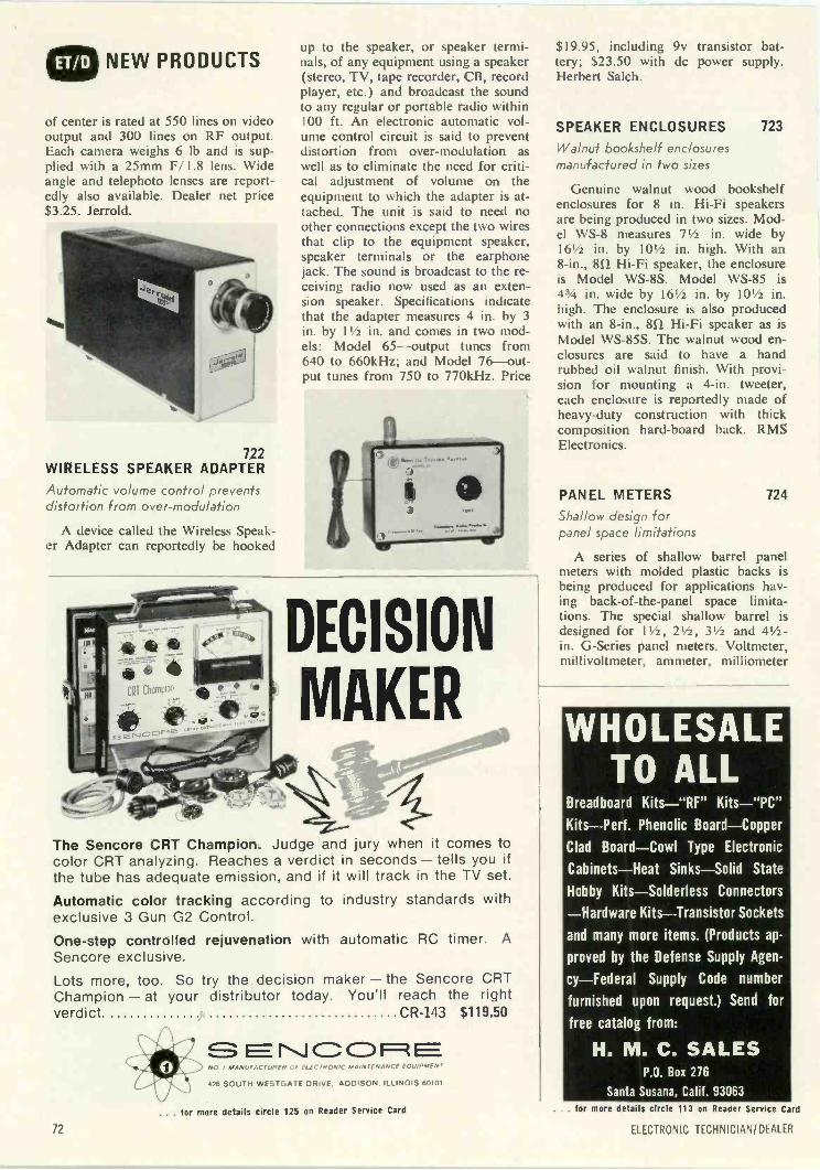
NEW PRODUCTS
of center is rated at 550 lines on videooutput and 300 lines on RF output.Each camera weighs 6 lb and is sup-plied with a 25mm F/1.8 lens. Wideangle and telephoto lenses are report-edly also available. Dealer net price$3.25. Jerrold.
722WIRELESS SPEAKER ADAPTER
Automatic volume control preventsdistortion from over -modulation
A device called the Wireless Speak-er Adapter can reportedly be hooked
up to the speaker, or speaker termi-nals, of any equipment using a speaker(stereo, TV, tape recorder, CB, recordplayer, etc.) and broadcast the soundto any regular or portable radio within100 ft. An electronic automatic vol-ume control circuit is said to preventdistortion from over -modulation aswell as to eliminate the need for criti-cal adjustment of volume on theequipment to which the adapter is at-tached. The unit is said to need noother connections except the two wiresthat clip to the equipment speaker,speaker terminals or the earphonejack. The sound is broadcast to the re-ceiving radio now used as an exten-sion speaker. Specifications indicatethat the adapter measures 4 in. by 3in. by 11/2 in. and comes in two mod-els: Model 65-output tunes from640 to 660kHz; and Model 76-out-put tunes from 750 to 770kHz. Price
DECISION
MAKER
The Sencore CRT Champion. Judge and jury when it comes tocolor CRT analyzing. Reaches a verdict in seconds - tells you ifthe tube has adequate emission, and if it will track in the TV set.
Automatic color tracking according to industry standards withexclusive 3 Gun 02 Control.
One-step controlled rejuvenation with automatic RC timer. A
Sencore exclusive.
Lots more, too. So try the decision maker - the Sencore CRTChampion - at your distributor today. You'll reach the rightverdict. CR-143 $119.50
1"1001=1ENO. I MANUFACTURER 1-n. ELECTRONIC MAINTENANCE EQUIPMENT
426 SOUTH WESTGATE DRIVE, ADDISON, ILLINOIS 60101
$19.95, including 9v transistor bat-tery; $23.50 with dc power supply.Herbert Salch.
SPEAKER ENCLOSURES 723
Walnut bookshelf enclosuresmanufactured in two sizes
Genuine walnut wood bookshelfenclosures for 8 in. Hi-Fi speakersare being produced in two sizes. Mod-el WS -8 measures 71/2 in. wide by161/2 in. by 101/2 in. high. With an8 -in., 81), Hi-Fi speaker, the enclosureis Model WS -8S. Model WS -85 is43A in. wide by 161/2 in. by 101/2 in.high. The enclosure is also producedwith an 8 -in., 8f), Hi-Fi speaker as isModel WS -85S. The walnut wood en-closures are said to have a handrubbed oil walnut finish. With provi-sion for mounting a 4 -in. tweeter,each enclosure is reportedly made ofheavy-duty construction with thickcomposition hard -board back. RMSElectronics.
PANEL METERS 724
Shallow design forpanel space limitations
A series of shallow barrel panelmeters with molded plastic backs isbeing produced for applications hav-ing back -of -the -panel space limita-tions. The special shallow barrel isdesigned for 11/2, 21/2, 31/2 and 41/2 -in. G -Series panel meters. Voltmeter,millivoltmeter, ammeter, milliometer
WHOLESALETO ALL
Breadboard Kits-"RF" Kits-"PC"Kits-Perf. Phenolic Board-Copper
Clad Board-Cowl Type Electronic
Cabinets-Heat Sinks-Solid State
Hobby Kits-Solderless Connectors
-Hardware Kits-Transistor Sockets
and many more items. (Products ap-
proved by the Defense Supply Agen-
cy-Federal Supply Code number
furnished upon request.) Send for
free catalog from:
H. M. C. SALESP.O. Box 276
Santa Susana, Calif. 93063
. for more details circle 125 on Reader Service Card
72
. for more details circle 113 on Reader Service Card
LL LC IRONIC TECHNICIAN/DEALER
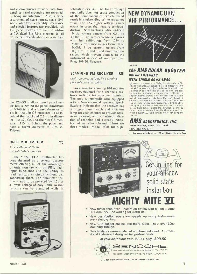
and microammeter versions with frontpanel or bezel mounting are reported-ly being manufactured. Also, a wideassortment of scale ranges, scale divi-sions, ohm/volt capability, resistanceand special features are provided. AllGS panel meters are said to utilizeself -shielded Bar -Ring magnets in alldc meters. Specifications indicate that
the 120 -GS shallow barrel panel me-ter has a behind -the -panel dimensionof 0.940 in. and a barrel diameter of1.5 in.; the 220 -GS measures 1.113 in.behind the panel and 2.2 in. in diame-ter; the 320 -GS and the 420 -GS mea-sure 1.113 in. behind the panel andhave a barrel diameter of 2.75 in.Triplett.
HI -LO MULTIMETER 725
Low voltage of 0.08vfor solid-state devices
The Model FE21 multimeter hasbeen designed as a general purposemeter offering all of the advantagesof instant -on use with an FET, high -input impedance and the ability toread resistors in circuit without dis-connecting them. The ohmmeter sec-tion is said to be powered by 1.5v ora lower voltage of only 0.08v so thatresistors can be measured while in
solid-state circuits. The lower voltagereportedly does not cause conductionof the semi -conductor, which wouldresult in a misreading of the resistancevalue. The I.5v higher voltage is nec-essary in cases that require semicon-duction. Specifications also indicate10 dc voltage ranges from 0.1v to3000v, 10 dc zero -center -scale rangeswith full calibration from .05v toI500v, 7 resistance ranges from I K to1000M, 9 dc current ranges from100p,a to I a and fused multiplier re-sistors which prevent damage to theinstrument in case of improper use.Price $99.50. Sencore.
SCANNING FM RECEIVER 726
Eight -channel automatic scanningplus selective listening
An automatic scanning FM monitorreceiver, designed for 8 channels, fea-tures switches for selective listening.The unit is reportedly also equippedwith a front -mounted speaker. Speci-fications indicate that the receiver hasa programming switch and indicatorlamp for each channel to provide lock -in or lock -out, with a flashing indica-tion of scanning and a steady indica-tion of an active channel. There arethree models: Model BCH for high -
NEW DYNAMIC UHF/
VHF PERFORMANCE...II1Of -- -
#CB -22
the RMS COLOR -BOOSTERCOLOR ANTENNAS
WITH SINGLE DOWN -LEAD#CB -22. 22 elements, #C6-28, 28 elements, #CB -34: 34 elements. All designed to add mileage to UHFand VHf TV reception. Each antenna is actually twoantennas in one-the front section for UHF-the rearsection for VHF-plus a corner array reflector toamplify desired signals from the front and to screenout all undesired signals from the rear. Brings inclearest reception on Channels 2 to 83 free of co -channel interference and ghosts. Model SP -332 UHF/VHF quality Splitter is included with each antennato facilitate simple single -line installation. The CBseries antennas feature Reynolds Aluminum weather-proof COLORWELD Gold finish! Write for completespect-
MIS ELECTRONICS, INC.50 Antin Place, Bronx, N.Y. 10462
Tel. (212) 892-6700
. . . for more details circle 123 on Reader Service Card
for
yo new
solid state
instant -on
MIGHTY MITE SE Now faster than ever. Instant -on action with all solid state
FET circuitry-no waiting for warm-up. New push-button cpera.ion speeds up every test-saves
you valuable time. New 13th socket checks still more tubes-now over 3000
including foreign. New hi -style case-vinyl-clad and brushed steel. A profes-
sional instrument desigfled for professionals.
At your distribuor now, TC-154 only $99.50NCORNO , MAN,' AC uRf11 Of ELECTRONIC MAINTENANCE EQUIPME
426 SOUTH WESTGATE DRIVE, ADDISON. ILLINOIS 60101
. for mere details circle 126 on Reader Service Card
AUGUST 1970 73
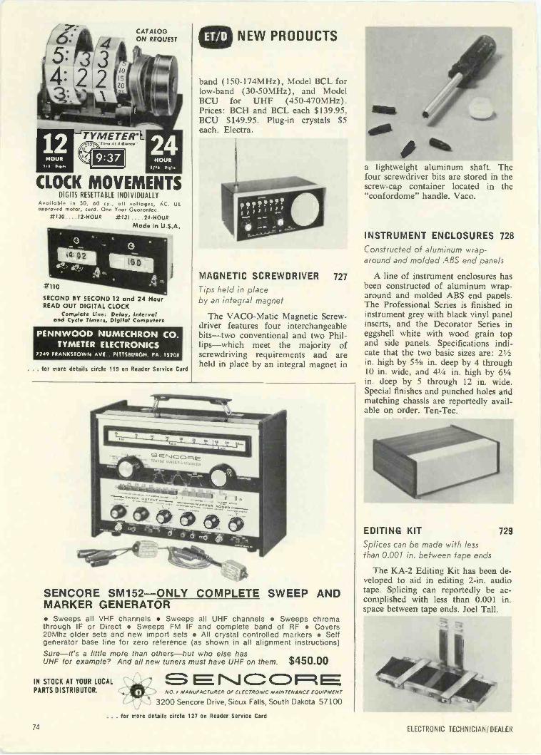
6.:
4.
12HOUR
CATALOGON REQUEST
--'TYMETER*At A Oldpne
CLOCK MOVEMENTSDIGITS RESETTABLE INDIVIDUALLY
Avaoloble in 50, 60 cy , oll voltages, ACapproved motor, cord. One Year Guarantee.
#130....12 -Noun #131 . 24 -HOUR
Made in U.S.A.
=filo
SECOND BY SECOND 12 and 24 HourREAD OUT DIGITAL CLOCK
Complete Line: Delay, Intervaland Cycle Timers, Digital Computers
UL
PENNWOOD NUMECHRON CO.TYMETER ELECTRONICS
/249 FRANKSTOWN AVE PITTSBURGH PA 1520$
. . . for more details circle 119 on Reader Service Card
NEW PRODUCTS
band (150-174MHz), Model BCL forlow -band (30-50MHz), and ModelBCU for UHF (450-470MHz).Prices: BCH and BCL each $139.95,BCU $149.95. Plug-in crystals $5each. Electra.
MAGNETIC SCREWDRIVER 727
Tips held in placeby an integral magnet
The VACO-Matic Magnetic Screw-driver features four interchangeablebits-two conventional and two Phil-lips-which meet the majority ofscrewdriving requirements and areheld in place by an integral magnet in
SENCORE SM152-ONLY COMPLETE SWEEP ANDMARKER GENERATOR Sweeps all VHF channels Sweeps all UHF channels Sweeps chromathrough IF or Direct Sweeps FM IF and complete band of RF Covers20Mhz older sets and new import sets All crystal controlled markers Selfgenerator base line for zero reference (as shown in all alignment instructions)Sure-it's a little more than others-but who else hasUHF for example? And all new tuners must have UHF on them. $450.00
IN STOCK AT YOUR LOCAL
PARTS DISTRIBUTOR.r\ICCD1t
NO. MANUFACTURER OF ELECTRONIC MAINTENANCE EQUIPMENT
3200 Sencore Drive, Sioux Falls, South Dakota 57100
a lightweight aluminum shaft. Thelour screwdriver bits are stored in thescrew -cap container located in the"confordome" handle. Vaco.
INSTRUMENT ENCLOSURES 728
Constructed of aluminum wrap-around and molded ABS end panels
A line of instrument enclosures hasbeen constructed of aluminum wrap-around and molded ABS end panels.The Professional Series is finished ininstrument grey with black vinyl panelinserts, and the Decorator Series ineggshell white with wood grain topand side panels. Specifications indi-cate that the two basic sizes are: 21/2in. high by 5% in. deep by 4 through10 in. wide, and 41/4 in. high by 61/4in. deep by 5 through 12 in. wide.Special finishes and punched holes andmatching chassis are reportedly avail-able on order. Ten-Tec.
qt3EDITING KIT 729
Splices can be made with lessthan 0.001 in. between tape ends
The KA-2 Editing Kit has been de-veloped to aid in editing 2 -in. audiotape. Splicing can reportedly be ac-complished with less than 0.001 in.space between tape ends. Joel Tall.
'tog
. for more details circle 127 on Reader Service Card
71 ELECTRONIC TECHNICIAN/DEALER
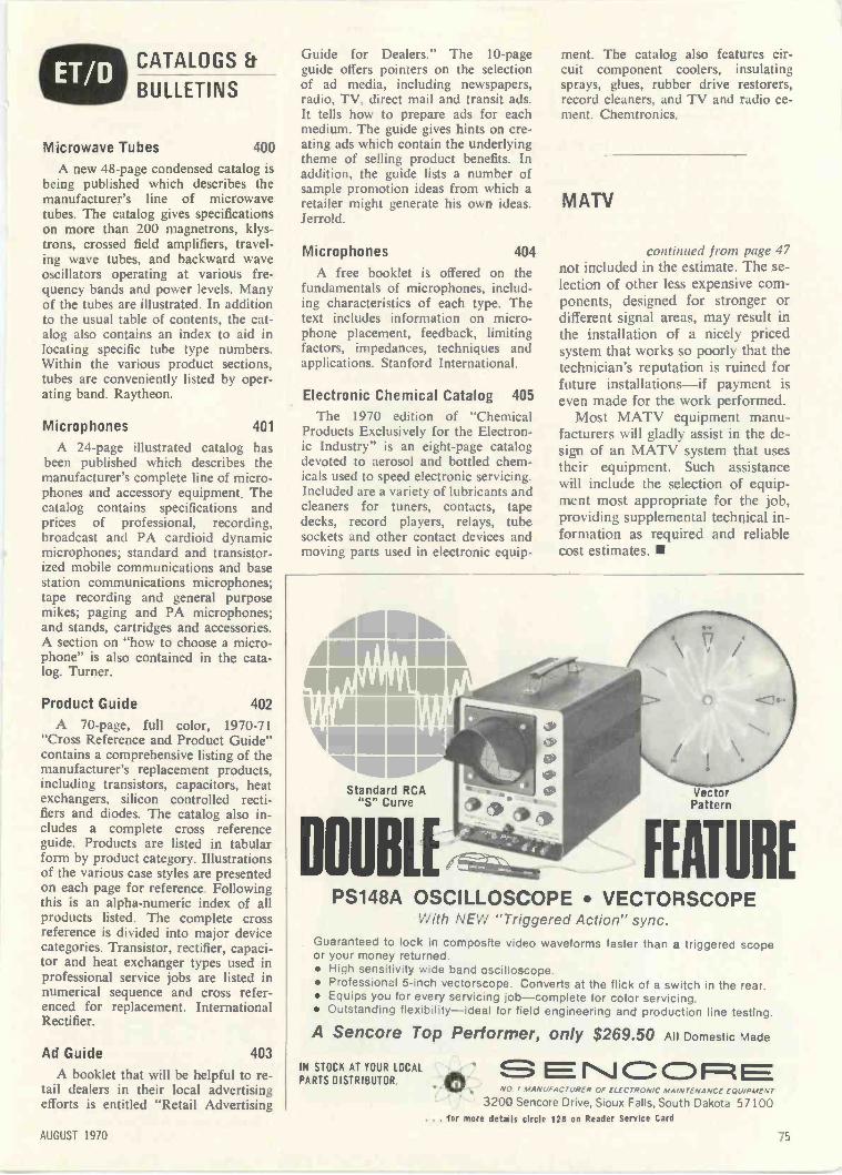
CATALOGS
BULLETINS
Microwave Tubes 400
A new 48 -page condensed catalog isbeing published which describes themanufacturer's line of microwavetubes. The catalog gives specificationson more than 200 magnetrons, klys-trons, crossed field amplifiers, travel-ing wave tubes, and backward waveoscillators operating at various fre-quency bands and power levels. Manyof the tubes are illustrated. In additionto the usual table of contents, the cat-alog also contains an index to aid inlocating specific tube type numbers.Within the various product sections,tubes are conveniently listed by oper-ating band. Raytheon.
Microphones 401
A 24 -page illustrated catalog hasbeen published which describes themanufacturer's complete line of micro-phones and accessory equipment. Thecatalog contains specifications andprices of professional, recording,broadcast and PA cardioid dynamicmicrophones; standard and transistor-ized mobile communications and basestation communications microphones;tape recording and general purposemikes; paging and PA microphones;and stands, cartridges and accessories.A section on "how to choose a micro-phone" is also contained in the cata-log. Turner.
Product Guide 402
A 70 -page, full color, 1970-71"Cross Reference and Product Guide"contains a comprehensive listing of themanufacturer's replacement products,including transistors, capacitors, heatexchangers, silicon controlled recti-fiers and diodes. The catalog also in-cludes a complete cross referenceguide. Products are listed in tabularform by product category. Illustrationsof the various case styles are presentedon each page for reference. Followingthis is an alpha -numeric index of allproducts listed. The complete crossreference is divided into major devicecategories. Transistor, rectifier, capaci-tor and heat exchanger types used inprofessional service jobs are listed innumerical sequence and cross refer-enced for replacement. InternationalRectifier.
Ad Guide 403
A booklet that will be helpful to re-tail dealers in their local advertisingefforts is entitled "Retail Advertising
Guide for Dealers." The 10 -pageguide offers pointers on the selectionof ad media, including newspapers,radio, TV, direct mail and transit ads.It tells how to prepare ads for eachmedium. The guide gives hints on cre-ating ads which contain the underlyingtheme of selling product benefits. Inaddition, the guide lists a number ofsample promotion ideas from which aretailer might generate his own ideas.Jerrold.
Microphones 404
A free booklet is offered on thefundamentals of microphones, includ-ing characteristics of each type. Thetext includes information on micro-phone placement, feedback, limitingfactors, impedances, techniques andapplications. Stanford International.
Electronic Chemical Catalog 405
The 1970 edition of "ChemicalProducts Exclusively for the Electron-ic Industry" is an eight -page catalogdevoted to aerosol and bottled chem-icals used to speed electronic servicing.Included are a variety of lubricants andcleaners for tuners, contacts, tapedecks, record players, relays, tubesockets and other contact devices andmoving parts used in electronic equip-
ment. The catalog also features cir-cuit component coolers, insulatingsprays, glues, rubber drive restorers,record cleaners, and TV and radio ce-ment. Chemtronics.
MAW
continued from page 47not included in the estimate. The se-lection of other less expensive com-ponents, designed for stronger ordifferent signal areas, may result inthe installation of a nicely pricedsystem that works so poorly that thetechnician's reputation is ruined forfuture installations-if payment iseven made for the work performed.
Most MATV equipment manu-facturers will gladly assist in the de-sign of an MATV system that usestheir equipment. Such assistancewill include the selection of equip-ment most appropriate for the job,providing supplemental technical in-formation as required and reliablecost estimates.
Standard RCA"5" Curve
VectorPattern
OUBLE FEATUREPS148A OSCILLOSCOPE VECTORSCOPE
With NEW "Triggered Action" sync.Guaranteed to lock in composite video waveforms faster than a triggered scopeor your money returned. High sensitivity wide band oscilloscope. Professional 5 -inch vectorscope. Converts at the flick of a switch in the rear. Equips you for every servicing job-complete for color servicing. Outstanding flexibility-ideal for field engineering and production line testing.
A Sencore Top Performer, only $269.50 All Domestic Made
IN STOCK AT YOUR LOCALPARTS DISTRIBUTOR. CD FR
NO I MANUFACTURER OF ELECTRONIC MAINTENANCE EQUIPMENT
3200 Sencore Drive, Sioux Falls, South Dakota 57100... for mare details circle 12$ en Reader Sande, Card
AUGUST 1970 75
If you're not using these tools of the trade,
YOU'RE LOSING MONEY!That's right. The combination of TUN -O -WASH and
TUN-O-BRITE for tuners increases customer satisfactionand eliminates costly callbacks. Super Frost Aid is far sup-erior to other circuit coolers in tracking down thermal inter-mittents. Without these professional chemical tools of thetrade, you're wasting hours of labor and a lot of referral bus-iness from satisfied customers.
TUN -O -WASHGETS TUNERS
REALLY CLEAN!
toitalganw.WO MINS fauRr
CHEMTRONICS
r
TI!FliDEGREASEFs asp Ot""
RISME ARO ., TARIM 1-1).Pawn' ". -vasearowootb410....-ija, --./.06111111 OM.
... " Nov.*,40.4, .IA"111;1
NO. 2400
TUN -0 -WASH is com-pletely unlike any othertuner spray on the market.TUN -O -WASH contains nolubricants. All of the pow-er of its high pressurespray is designed to dojust one job superlativelywell-to melt away grease,oil, dust, dirt, corrosionand any other foreign ma-terial that may be on thetuner contacts. No otherspray can even approachTUN -0 -WASH in pure clean-ing power. TUN -0 -WASH re-stores the tuner to its)riginal condition, leavingparts and contacts likenew. Especially good forremoving old, encrustedLiner sprays.
SUPERFROST AID
TAMES THERMAL
INTERMITTENTS FAST!
LEAVES NO LIQUID RESIDUE
FROST AID
OftwomoMi10. *IN
NO. 1550
Just let the chassis"cook" for an hour or soand then spray each com-ponent in the suspectedcircuit until you see a dra-matic change on the TVscreen or hear it on thespeaker. The last compon-ent you have sprayed isusually the defective one.
Some component coolersdon't work fast enough toenable you to be sure, butwith Super Frost Aid, thereaction is fast and defin-ite-as though you hadclicked a switch.
TUN-0-BRITETHE HEAVY DUTY TUNER
SPRAY WITH BUILT-INCONTACT BRIGHTENERS!
!!!NEWUIRESTORES
"t4TILY ENCRUST"TV TUNERS
-I,FOR
41,7 DUTY TURF pi
PO RVITO" r11°°it{
1-4 4.7' so7C.0, C
NO. BT -8
Polishes tuner contacts,removing all dirt and cor-rosion. Can't damage pre-cious metal platings be-cause polishing particlesare hollow - disintegrateafter initial wiping action.Leaves film of thick, pro-tective lubricant with morebody and staying powerthan any other aerosol lub-ricant on the market.
CHEMTRONICS CHEMTRONICS "c1260 RALPH AVENUEBROOKLYN, N. Y. 11236
. . . for more details circle 105 on Reader Service Card
76
READERS SERVICEINDEX
ADVERTISER'S INDEXAmerican Telephone & Telegraph Co. .23
101 B & K Division, Dynascan Corp. 20102 Belden Corporation 34 & 35103 Book Club-Tab Books 66-69104 Book Club-Techmatics 63105 Chemtronics, Inc. 76106 Cornell-Dubilier 3rd Cover107 C R C Chemicals 60108 EICO Electronic Instruments Co.,
Inc. 2nd Cover109 Finney Co., The ..25110 General Electric Co. 26111 Grantham School of Engineering 76112 Heath Co., The ... .. 29113 Houle Mfg. Co. ..... 72114 Lakeside Industries 62115 Laran-Electronics, Inc. 60116 Lectrotech, Inc. ....... . 33117 Master Appliance Corp. 65118 Mosley Electronics, Inc. . 28119 Pennwood Numechron Co. 74120 Quietrole Co. 60121 RCA Parts & Accessories 71
RCA Picture Tubes122 RCA Test Equipment123 RMS Electronics, Inc.124 Rohn Mfg. Co125 Sencore, Inc.126 Sencore, Inc.127 Sencore, Inc.128 Sencore, Inc.129 South River Metal Products Co.
Sylvania Electric ProductsSylvania Electric Products
130 Tech Spray131 Tuner Service Corp.132 United Tel-Tronics Co.133 Workman Electronic Products, Inc.134 Workman Electronic Products, Inc.135 Xcelite, Inc.
Zenith Radio Corp.
NEW PRODUCTS
4th Cover2473317273747528273622195962706157
700 Intercom System 59701 Stereo Receiver 59702 AM/FM Radio and Tape Recorder 59703 Microphone 59704 Stereo Receiver 60705 Electronic Crossover 60706 Stereo System 61707 Speaker System 61708 Telephone Answering Machine 61709 PA Amplifiers 61710 Stereo Tape Player 62711 Base Transceivers 62712 Portable Cassette Recorders 62713 Frequency Counter 70714 Panel Meter 70715 Capacitor Chip Kit 70716 Tuner Spray 70717 Video Tape Recorder System 70718 Cassette Cartridge 71719 Terminal Installing Tool 71720 Controls 71721 TV Camera 71722 Wireless Speaker Adapter 72723 Speaker Enclosures 72724 Panel Meters 72725 Hi -Lo Multimeter 73726 Scanning FM Receiver 73727 Magnetic Screwdriver .. 74728 Instrument Enclosures 74729 Editing Kit 74
CATALOGS AND BULLETINS400 Microwave Tubes 75401 Microphones 75402 Product Guide 75403 Ad Guide 75404 Microphones 75405 Electronic Chemical Catalog 75
TEST INSTRUMENTS900 Sencore's Model 8E156901 Sencore's Model 39G26
Technicians, Earn Your Associate
DEGREEmostly by correspondence
Accredited by the Accdt. Comm. of National HomeStudy Council. G.I. Bill Approved. Free catalog.Write. Dept. T
Grantham School of Engineering1505 N. Western, Hollywood, Calif. 90027
. . . for more details circle 111 on Reader Service Card
ELECTRONIC TECHNICIAN/DEALER
FOR MORE INFORMATION fill out and mail today!Please send more informat on on items circled.
GET
MORE
FACTSNO POSTAGE
NECESSARY
Circle
the
Reader
Service
numbers
of those
items of
interest
to you.
OK
ADVERTISED PRODUCTS (Please type or print) 8/70
101 102 103 104 105 106 107 108 109
110 111 112 113 114 115 116 117 118 Name
119 120 121 122 123 124 125 126 27
128 129 130 131 132 133 134 135 36 Position
137 138 139 140 141 142 143 144 145
146 147 148 149 150 151 152 153 154 Company
TEST INSTRUMENTS Street900 901 902 903 904 905 906 907 908
NEW PRODUCTS City
700 701 102 703 704 705 706 707 708
709 710 711 712 7'3 714 715 716 717 State Zip Code
718 719 720 721 722 723 724 725 726
727 728 729 730 731 732 733 734 735 Please describe your type of business.
CATALOGS & BULLETINS
400 401 402 403 404 405 406 407 408
409 410 411 412 413 414 415 416 417
We: Inquiries serviced until November 6, 1970.
FOR MORE INFORMATION fill out and mail today!Please send more informztion on items circled.
ADVERTISED PRODUCTS (Please type or print) 8/70101 102 103 104 105 106 107 108 109
11C 111 112 113 114 115 116 117 118 Name
11E 120 121 122 123 124 125 126 127
126 129 130 131 132 133 134 135 136 Position
137 138 139 140 141 142 143 144 145
146 147 148 149 150 151 152 153 154 Company
TEST INSTRUMENTS Street900 901 902 903 904 905 906 907 908
NEW PRODUCTS City
703 701 702 703 704 705 706 707 708
769 710 711 112 113 714 715 716 717 State Z p Code
718 719 720 721 722 723 724 725 726
727 728 729 730 731 732 733 734 135 Please describe your type of busiress.
CATALOGS & BULLETINS
4(0 401 402 403 404 405 406 407 408
4C9 410 411 412 413 414 415 416 417
Kate: Inquiries serviced until November 6, 1970.
Name
Title
Firm
Street
City
State Zip
GET THIS FREE BONUS WITH YOUR PERSONAL SUB
SCRIPTION TO ELECTRONIC TECHNICIAN/DEALER!
Enter your subscription for a two- or three-year term an(we'll send you the new TEKFAX 109 Boo',( of Schematics-FREE!
] $10 for 3 Years $8 for 2 Years - $5 for 1 Year
Payment Enclosed II Bill Me Later
PLEASE CHECK BELOW:1. In the TV, Radio anc other consumer products fields, is your firmPRIMARILY a: (check mcst descriptive item)
Retai,er with servic!department
Li Servi:e/repair firmwith some -etail
Industrial electronic!service firm
MancfacturerOther (please descr le)
2. Title- (please check one)
(11 Owner, manager, buyer,other executive
Suv ce manager Se -v ce repairman or
otter employee
If you are renewing your subscription, check here and attach your address lajel. If you renewyour subscription for 2 to 3 years, you are still eligible to receive the TEKFAX 109 as your free bonus.
BUSINESS REPLY MAILNO POSTAGE STAMP NECESSARY IF MAILED IN THE UNITED STATES
POSTAGE WILL BE PAID BY
Reader Service Department
ELECTRONICTECHNICIAN / DEALERHARBRACE BUILDING, DULUTH, MINNESOTA 55802
BUSINESS REPLY MAILNO POSTAGE STAMP NECESSARY IF MAILED IN THE UNITED STATES
POSTAGE WILL BE PAID BY
Reader Service Department
ELECTRONICTECHNICIAN / DEALERHARBRACE BUILDING, DULUTH, MINNESOTA 55802
FIRST CLASS
PERMIT NO. 665
DULUTH, MINNESOTA
FIRST CLASS
PERMIT NO. 665DULUTH, MINNESOTA
BUSINESS REPLY MAILNO POSTAGE STAMP NECESSARY IF MAILED IN THE UNITED STATES
POSTAGE WILL BE PAID BY
Circulation Department
ELECTRONICTECHNICIAN / DEALERHARBRACE BUILDING, DULUTH, MINNESOTA 55802
FIRST CLASS
PERMIT NO. 665DULUTH. MINNESOTA
GET
MORE
FACTSNO POSTAGE
NECESSARY
GET
MORE
FACTSNO POSTAGE
NECESSARY
FOR
ONLY
PENNIES
PER
MONTH-YOUR
OWN
PERSONAL
COPIES
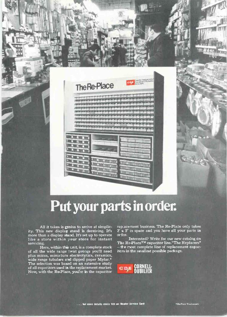
simissisimlowasiiimi are him maimmi.meimmossiessimiliamin amaisaniamman
isimaimiansissesagunimiiislam IN ino mum num
lasamininsannuaimaimmai mingimm
Put your parts in order.All it takes is genius to arrive at simplic-
ity. This new display stands deceiving. It'smore than a display stand. It's set up to operatelike a store within your store for instantserv:cing.
Here, withh thic Lint, is a complete stockof all the wide range -.:wist prongs you'll needplus micas, miniature electrolytics, ceramics,wide range tubulars e-xl dipped paper Mylar.*The selection was based on an extensive studyof al: capacitors used in the replacement market.Now, with the Re -?lace, you're in the capacitor
rzo acement busiress. The Re-Pla:e only takes2' 1, 5' :n space and you leave ell your parts inarl
Interested? Write for our new catalog cnThe RePlacTM capacitor line.`The Replacer?
e most complete line of replacement capac-itc Ira in the smallest possible package.
... ter more details circle 106 on Realer ie-vice Card 'IL Pont Trademwk
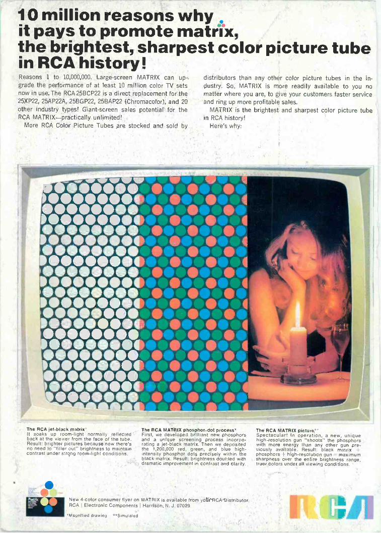
10 million reasons whyit pays to promote matrix,the brightest, sharpest color picture tubein RCA history!Reasons 1 to 10,000,000. Large -screen MATRIX can up-grade the performance of at least 10 million color TV setsnow in use. The RCA 25BCP22 is a direct replacement for the25XP22, 25AP22A, 25BGP22, 25BAP22 (Chromacolor), and 20other industry types! Giant -screen sales potential for theRCA MATRIX-practically unlimited!
More RCA Color Picture Tubes are stocked and sold by
distributors than any other color picture tubes in the in-dustry. So, MATRIX is more readily available to you nomatter where you are, to give your customers faster serviceand ring up more profitable sales.
MATRIX is the brightest and sharpest color picture tubein RCA history!
Here's why:
The RCA jet-black matrixIt soaks up room -light normally reflectedback at the viewer from the face of the tube.Result: brighter pictures because now there'sno need to "filter out" brightness to maintaincontrast under strong room -light conditions.
0
The RCA MATRIX phosphor -dot process*First, we developed brilliant new phosphorsand a unique screening process incorpo-rating a jet-black matrix. Then we depositedthe 1,200,000 red, green, and blue high -intensity phosphor dots precisely within theblack matrix. Result: brightness doubled withdramatic improvement in contrast and clarity.
New 4 -color consumer flyer on MATRIX is available from your RCA Distributor.RCA I Electronic Components Harrison, N. J. 07029
'Magnified drawing **Simulated
The RCA MATRIX pictureSpectacular! In operation, a new, uniquehigh -resolution gun "shoots" the phosphorswith more energy than any other gun pre-viously available. Result: black matrix !-
phosphors high -resolution gun maximumsharpness over the entire brightness range,truer colors under all viewing conditions.