IWATSU Displacement & Thickness Meter elements, crystal vibration, ... Sensor head Piezo-electric...
16
NON-CONTACT SENSORS DISPLACEMENT METER/ THICKNESS METER DIGEST CATALOG DISPLACEMENT METER/ THICKNESS METER DIGEST CATALOG Displacement Meter ST-3571A Displacement Meter ST-3512 Displacement Meter ST-3501 Displacement Meter ST-3521 Displacement Meter ST-3511 Thickness Meter ST-3523 Fiber Optic Displacement Meter ST-3711 Moisture Meter ST-3808 Thickness Meter ST-3525 Anglevel Meter AL-12 Heterodyne Laser Displacement Meter ST-3761
Transcript of IWATSU Displacement & Thickness Meter elements, crystal vibration, ... Sensor head Piezo-electric...

NON-CONTACT SENSORS
DISPLACEMENT METER/THICKNESS METER
DIGEST CATALOG
DISPLACEMENT METER/THICKNESS METER
DIGEST CATALOGDisplacement Meter ST-3571A
Displacement Meter ST-3512
Displacement Meter ST-3501
Displacement Meter ST-3521
Displacement Meter ST-3511
Thickness Meter ST-3523
Fiber Optic Displacement Meter ST-3711
Moisture Meter ST-3808Moisture Meter ST-3808
Thickness Meter ST-3525
Anglevel Meter AL-12
Heterodyne Laser Displacement Meter ST-3761

2
NON-CONTACT DISPLACEMENT METERTHICKNESS METER
The meters are called “Non-contact displacement meter” or “Thickness meter”, and detect physical quantity, such as displacement, vibration, and
thickness, with non-contact probes, then convert to electrical quantity and measure original physical quantity accurately. The sensor that is
integrated inside the probes detects the quantity. The methods are capacitance, laser, fiber optics etc. As every method has its own characteristics,
you can choose its usage. As measurements are performed using a non-contact method, you can measure accurately without affecting the object
being tested.
Demands on the non-contact displacement meter have grown vastly in recent years, such as semiconductors, precision motors, various disks (such
as hard disks and compact disks, etc), and various films, and both meters have had to expand to meet those needs.
Application Field(1) Measurement of axial vibration, radial vibration, circularity, vibration, and acceleration:
precision motors, video cylinders, hard disks, compact disks, engines, and rollers for office appliances
(2) Measurement of board thickness, flatness, warping, roughness, scratches, edges, and size:
silicon wafers, various disks, glass, printed boards, films, and sheets
(3) Measurement of accuracy positioning and size:
semiconductor manufacturing machines, semiconductor manufacturing testers, processing machine for precision machines, machine parts
assembling, XY stage, and liquid level
(4) Measurement of vibration element oscillation, vibration times, vibration mode, and response characteristics:
piezo-electric elements, crystal vibration, ultrasonic vibration, and speakers
(5) Measurement of external dimension:
wire/pipes, tapes/sheets, copy drums, rubber rollers, precision parts, and assembly parts
Comparing Each Method
ST-3501
ST-3511
ST-3512
ST-3521
ST-3571
ST-3525
ST-3523
ST-3711
ST-3761
ST-3808
The probe and object being tested generate capacitance, and capacitance changes
according to the distance “D”. A capacitance-voltage conversion circuit measures
displacement to output voltage, which is proportional to “D”.
The principle is simple, and it measures minute displacement stability and precisely.
The measurement objects are a conductor and semiconductor.
Fix the displacement probe with the known distance “c” on both sides, and measure
“a” and “b”, and then thickness “t” can be expressed in the following formula.
t = c - (a + b)
Fix probe and ground electrode with the known distance “D”, and insert the insulation
of thickness “t” being tested in between.
As the capacitance varies, being proportional to the dielectric constant of the
insulator and thickness “t”, the thickness “t” of the object being tested is measured
when calibrated with the same insulator beforehand.
Produces probes that bundle fiber optics for transmitting and receiving. Is measured
using the principle that light quantity, which reflects to the receiving fiber from the
object being tested, is changed by the distance “D”. It is also suitable to measure
vibrators that change to “D” rapidly.
Using an optical heterodyne interferometer, displacement can be measured using the
beat signal phase difference generated by the optical path difference of the measur-
ing beam and reference beam. The reference beam is generated when the original
light overlaps the light created when the laser is reflected off the object being tested.
Using a laser allows you to measure the operating distance between tiny measuring
spots and the object being tested. Also it is possible to measure a variety of speeds,
from motionless surfaces (which was difficult with the Doppler vibrometer) to high-
speed vibrating surfaces.
This meter is a capacity-voltage transducer in principal. The transducer detects the
capacity and converts equivalently, then measures the moisture percentage of a
dielectric, such as ink. Use this machine after calibrating the known moisture
percentage.
Cap
acita
nce
Sensor method Principle and characteristic Model name
Displace-
ment meter
Thickness
meter
(Conductor)
Thickness
meter
(Insulation)
Fiber optics
Heterodyne Laser
Displacement
Meter
Moisture meter
Probe
Object being tested
D
Probe
ProbeObject being tested
t
a
bc
t = c - (a + b)
ProbeObject being tested
D
Ground electrode
t
InkProbe
Fibe
r opt
ics
Ref
lect
ed li
ght
Rec
eive
r
Tran
smitt
er
Tran
smitt
ing
Rec
eivi
ng
Workingdistance
Projection/receiving lightbeam
Sensor head

3
Measurement of radial vibration and axial vibration
Measurement of gap
Example of system application
Measurement of sheet thickness
Measurement of polygon mirror vibration
Measurement of piezo-electric element vibration
Measurement of silicon wafer thickness
Measurement of piezo-electric element displacement
NON-CONTACT DISPLACEMENT METERTHICKNESS METER
Measurement Application Examples
Motor
Probe
Probe
Axial
Radial
Gap
Sheet
Thickness meter probe
Thickness meter main unit
Oscilloscope
Controller
Spindle motor
Hard disk
Personalcomputer
Probe
Silicon wafer
Probe
Piezo-electric element
Probe
Probe
Polygon mirror
Laser sensor section
Main unit
Main unit
Rotator
Displacement meter probe
Oscilloscope
Personal computer
(Capacitance) (Capacitance)
(Capacitance) (Fiber optics)
(Capacitance and laser) (Capacitance)
(Capacitance) (Heterodyne)
Sensor head
Piezo-electric element

4
Application of Displacement Meter and Thickness Meter —How to evaluate high speed and high precisionmotors (rotators)e.g. Measurement of radial vibration and axial vibration
Do you have trouble evaluating high speed and high accuracy motors even though you made them?
RRO and NRRO measurement of high speed and high accuracy motors (rotators)To evaluate the performance of motors (rotators such as HDD, FD, MO, DVD, VTR), it is necessary to measure the vibration of the
direction of an arrow as shown below in the actual operation.
We have a large assortment of probes to measure accurately, even if the measurement objects are narrow or there are obstacles
around the measurement objects.
Exa
mpl
e 1
of a
dvan
ced
mea
sure
men
t
RRO (Repeatable Runout)
NRRO (Non-Repeatable Runout)
Probe
Work
Gap
Gap
Probe
Probe
Measuring surface
Measuring surface
Measuring surface
45°
45°45°
MIN ø0.5
MIN ø0.5Radial
Axial
MIN ø0.5
MIN ø0.5
ProbeEdgeAxial
Radial
Exa
mpl
e 2
of a
dvan
ced
mea
sure
men
t
NON-CONTACT DISPLACEMENT METERTHICKNESS METER
RRO(TIR)
NRRO
This is a waveform whenobserved with an XY modeoscilloscope using 2 probes.
It is an ideal measuring way.
Construction example —the case of measurement of axial—When observing the rotator with 2 probes as shown,
the Lissajous waveform can be seen. You can also
see which way the axis vibrates, and the influence of
the machine on the parts around the rotator, etc.
Use good quality fixtures to get good performance out of the metersTo measure in high resolution, it is necessary to use high-resolution meters and good quality fixtures to enhance the meters'
performance.
Along with usability, a structure that can withstand of surrounding vibrations, or fixtures that do not resonate with rotator are
required.
Standard fixture with magnetic stand straight and 45°This standard fixture is for a probe.
It has a magnetic stand to use on the granite surface plate.
Can adjust the gap to XYZ.
1 2
3
(10kHz) (1kHz)
(100Hz)CHECK
PROBE ZERO
POWER
OFF
ON
AC
DC
OUTPUT
2020 0 4040 +
A
DISPLACEMENT METER
ST-3511
1 2
3
(10kHz) (1kHz)
(100Hz)CHECK
PROBE ZERO
POWER
OFF
ON
AC
DC
OUTPUT
2020 0 4040 +
A
DISPLACEMENT METER
ST-3511
RRO
NRRO

5
Various probesWe have a large assortment of probes, such as those with an electrode of width 0.1mm and ø0.2mm, and those with an elec-
trode shape of straight, 45° cut V, a half circle, 45° cut, and V cut. Representative probes are shown below.
Please contact us about the specifications or other details.
(The following specifications are when use with a displacement meter ST-3511.)
Motor ø0.5
27
Probe
ST-0539A probe usage example
NON-CONTACT DISPLACEMENT METERTHICKNESS METER
ST-0532P probe
ST-0538B probe usage example
Serial number
Electrode dimension
27(3
)
(84)
30
82
Guard Ring
ST
-05
39
AP
RO
BE
Ø1.5
Ø16
Ø0.5
Ø0.3
0-0.1
Specification ST-0539A Probe
Measuring range 30µm ± 15µm
±3V
±2% F.S
0.2V/µm
100nm (10kHz)
ø0.3mm
Output voltage
Sensitivity
Resolution
Electrode dimension
Accuracy
Serial number
Guard ring
Ground ring
ST
-05
38
XE
PR
OB
E
Ø16 0-0.1
2238
(84)
20
AA
Measuring electrode A-A Vision S=2/1
Measuring electrode
Ø3
Ø3
Ø5
Ø7
Ø0.5
Ø15.9
0.75
Specification ST-0538XE Probe
Measuring range 75µm ± 50µm
±5V
±2% F.S
0.1V/µm
100nm (10kHz)
ø0.5mm
Output voltage
Sensitivity
Resolution
Electrode dimension
Accuracy
Guard ring
3010
(6)
45°
ø15.8
ø8
ø3
Measuring electrode
Guard ring
Measurement electrode section details S=5/1
Specification ST-0532P ProbeMeasuring range
±5V
±2% F.S
100nm (10kHz)
ø1.8mm
Output voltage
Sensitivity
Resolution
Electrode dimension
Accuracy
0.05V/µm
200µm ± 100µm
Guard Ring
Guard Ring
ø16 0-0.1
1010
Measuring electrode
Measuringelectrode
90°0.25
ø2
ø0.5
ø8
(ø15.9)
Measure 5:1
Specification STSpecification ST-0538B Probe-0538B ProbeMeasuring range 50µm ± 25µm
±5V
±2% F.S
0.2V/µm
10nm (10kHz)
ø0.5mm
Output voltage
Sensitivity
Resolution
Electrode dimension
Accuracy
Probe
Motor
45°
Specification ST-0536D Probe-0536D ProbeMeasuring range
±5V
±2% F.S
0.1V/µm
100nm (10kHz)
ø1.0mm
Output voltage
Sensitivity
Resolution
Electrode dimension
Accuracy
100µm ± 50µm
ST
-0
53
6D
PR
OB
E
Ø16 0-0.1
2510
(72)
Ø8
Ø1.0
Ø2
Serial number
Measuring electrode

6
Extra Fine Probe ø0.2 DisplacementMeter ST-3571A
The capacitive displacement meter ST-3571A measures the minute
displacement of metals etc, using a non-contact method and is a
device that outputs voltage with high precision in proportion to the
displacement. Especially, the extra fine probe is suitable for measur-
ing precise high-speed disks, precision motors, spindles, and high-
speed vibrators on high sensitive and broadband. It is also suitable
for measuring and analyzing with oscilloscopes and FFT analyzers.
Features Extra fine probes allow the measurement of compact object
displacement. (The electrode diameter of an extra fineprobe is ø0.2mm.)
Measurements are performed using a high-resolution andprecise non-contact method.
Accurate analog voltage, which is proportional to thedisplacement, is outputted.
The bandwidth is wide (DC to 10 kHz), with a fast response time. The bandwidth is converted by a switch. Each metal can be measured under the same conditions
with no influence from a magnetic field or magneticsubstance.
Performance(With Probe ST-0702A)
ST-0702A (standard)
75 ± 25µm
0.4V/µm
±2% F.S
ø0.2mm
(ø1 × 5)+(ø2.1 × 5)+
(ø8 × 10)+(ø16 × 74) mm
1.5m
Multi-prong, round shape
Approximately 100g
Probe
Measuring range
Sensitivity
Accuracy
Electrode dimension
Dimensions
Cable length
Connector
Weights
Type of measurement ......Measuring range ..............Output voltage .................Sensitivity ........................Accuracy ..........................Offset function ..................Bandwidth ........................
Output resistance ............Power source ...................Power consumption .........Operation environment ....Dimensions ......................Weights ............................Accessories .....................
Display .............................Alarm ...............................
Note) The combinations of probe and equipment are specified. Changes in the measurement range must be custom-written. We also design and make probes that are not listed in our catalogs.Probes are sold separately.
CAPACITIVE DISPLACEMENT METER ST-3571A
Probes for Displacement MetersST-0702J2(custom-made)
100 ± 50µm
0.2V/µm
±2% F.S
ø0.2mm
(ø2.1 × 10)+(ø2.1 × 5)+
(ø8 × 10)+(ø16 × 74) mm
1.5m
Multi-prong, round shape
Approximately 100g
ST-0742A2 (custom-made)
100 ± 50µm
0.2V/µm
±2% F.S
0.1 × 0.35mm(Square)
(ø3 × 10)+(ø8 × 10)+
(ø16 × 74) mm
1.5m
Multi-prong, round shape
Approximately 100g
ST-0702A
ST-0702J2
ST-0742A2
50 100 150
+ 1 0 V
- 1 0 V
0
Ou
tpu
t v
olt
ag
e
Interval µm)(
Capacitive75 ± 25µm+10V~-10V (F.S)0.4 V/µm±2% F.S (23 ± 5˚C, less than 80% R.H)Approximately ±10% (F.S)DC~10kHz(-3dB) (can be switched to approximately5kHz, 1kHz, 500Hz and 100Hz)Approximately 50Ω90VAC~250VAC 50/60Hz24W ± 20% (with AC100V)0~40˚C, less than 85% R.HApproximately 80W × l70H × 320L (mm)Approximately 3kgPower cord(1), Fuse(2), Coaxial cable(1),Ground lead (1), Instruction manual(1)Over rangeDC30V,1A (input resistance) Alarm will close whenon the + side of over range.
[Measurement of 1 inch motor] [Displacement and output voltage](ST-0742A2 Electrode dimension 0.1 × 0.35mm)
Measuringsurface

7
Measuring electrode
Guard ring
Shielding case(Ground)
Electric field
Ground electrode(Object)
Effective electric field
Shielding case
Measuring electrode
Guard ring
Probes for Displacement Meters
The displacement meter ST-3512 measures minute displacement of
metals etc, using non-contact method and is a device that outputs
voltage with high precision in proportion to the displacement.
ST-3512 is suitable for measuring and analyzing disks that rotate on
high sensitive and broadband, especially precision motors, spindles,
and also high speed vibrator with oscilloscopes or FFT analyzers.
CAPACITIVE DISPLACEMENT METER ST-3512
[The structure of probes and effect of the guard ring]The electric field between the two electrode plates is made even by adding the
same potential around the electrode.
Therefore, the even section of the measuring electrode can be C-V converted.
(This is called the “Guard Ring”)
Options Various probes = Wide bandwidth 100kHz
ST-0535A3 (standard)
50 ± 25µm
0.2V/µm
±1% F.S
10nm
5nm
1.5nm
0.6nm
ø1.2mm
(ø5 × 20) +
ø16 × 84mm
1.5m
Multi-prong, round shape
Approximately 140g
Probe
Measuring range
Sensitivity
Accuracy
Resolution(40kHz)
Resolution(10kHz)
Resolution(1kHz)
Resolution(100Hz)
Electrode dimension
Dimensions
Cable length
Connector
Weights
Super-High Resolution DisplacementMeter ST-3512
ST-0535A3
Note) The combinations of probe and equipment are specified. Changes in themeasurement range must be custom-written. We also design and makeprobes that are not listed in our catalogs. Probes are sold separately.
Features A resolution of 5nm (10kHz) allows precise non-contact
measurements. (Available to measure objects less than0.5nm (max.) with the combination of optional probes andswitching the bandwidth.)
Accurate analog voltage, which is proportional to thedisplacement, is outputted.
The bandwidth is wide (40kHz, standard), with a fastresponse time. (can be increased to 100kHz with options.)
The bandwidth (filter) is converted by a switch. Each metal can be measured under the same conditions with
no influence from a magnetic field or magnetic substance. The thin probes are available. (option)
Performance(With Probe ST-0535A3)
Type of measurement ......Measuring range ..............Output voltage .................Sensitivity ........................Accuracy ..........................Resolution ........................Bandwidth ........................
Output resistance ............Power source
Voltage ..........................Power consumption ......
Operation environment ....Dimensions ......................Weights ............................Accessories .....................
Capacitive50 ± 25 µm+5V ~ -5V (F.S)0.2V/ µm±1% F.S (23 ± 5 ˚C, 80% R.H)10 nm(40kHz), 0.6nm(100Hz)DC ~ 40kHz(-3 dB) (can be switchedapproximately 10kHz, 1kHz, 100Hz)Approximately 50Ω
AC100V ±10% 50 /60 Hz9W ± 20% (with AC100V)0 ~ 50 ˚C, less than 85% R.HApproximately 80W × l70H × 304L (mm)Approximately 2.8kg
Coaxial cable(1), Power cord(1), Instruction manual(1)

8
Probes for Displacement Meters
CAPACITIVE DISPLACEMENT METER ST-3501
Wide Measuring Range CapacitiveDisplacement Meter ST-3501
The displacement meter ST-3501 measures the displacement of
conductors, such as semiconductors and metals, using a non-contact
method and is a device that outputs voltage with high precision in
proportion to the displacement. Use ST-3511 with the connecting
oscilloscope, VOAC (digital multimeter) and recorder etc.
ST-0507 (standard) ST-0505B (standard) ST-0507S3 (custom-made)
0.1 ± 0.05mm 1.0 ± 0.5mm 0.1 ± 0.05mm
0.1V/ µm 10V/mm 0.1V/µm
±2% F.S ±1% F.S ±2% F.S
0.1µm 1µm 0.2µm
ø1.8mm ø5.5mm ø1.68mm
(ø10 × 20) + ø16 × 70mm ø16 × 90mm (ø3 × 40) + ø16 × 82mm
1.5m 1.5m 1.5m
Multi-prong, round shape Multi-prong, round shape Multi-prong, round shape
Approximately 120g Approximately 120g Approximately 120g
Probe
Measuring range
Sensitivity
Accuracy
Resolution
Electrode dimension
Dimensions
Cable length
Connector
Weights
[Measurement of rotating vibration] [Displacement and output voltage]
Note) The combinations of probe and equipment are specified. Changes in the measurement range must becustom-written. Probes are sold separately.
ST-0507
ST-0505B
ST-0507S3
0.5 1.0 1.5
+ 5 V
- 5 V
0
Ou
tpu
t v
olt
ag
e
Interval (mm)
1 2
3
(10kHz) (1kHz)
(100Hz)CHECK
AC
OUTPUT
DISPLACEMENT METER
2020 0 4040 +
µ A
ST-3501
Features This meter is capacitive type. Measurements are performed using a non-contact method. Accurate analog voltage, which is proportional to the
displacement, is outputted. The bandwidth is wide, and is converted by a switch. The probe is compact, and the surroundings of the
electrode are completely sealed. Through probe selection, the measuring range can be
selected. We make the specially ordered probes as required.
Performance(With Probe ST-0505B)
Type of measurement ......Measuring range ..............Output voltage .................Sensitivity ........................Accuracy ..........................Resolution ........................Bandwidth ........................
Output resistance ............Power source
Voltage ..........................Power consumption ......
Operation environment .....Dimensions ......................
Weights ............................Accessories .....................
Capacitive1 ± 0.5mm+5 V~ -5 V (F.S)10 V/mm±1% F.S (23 ± 5 ˚C, 80% R.H)1µmDC~10kHz (-3dB) (can be switched to approximately1kHz and 100Hz)Less than 50Ω
AC100V ± 10% 50/60HzApproximately 17W (with AC100V)0 ~ 50 ˚C, less than 85% R.HApproximately 62W × l70H × 304L (mm)(except the protruding part)Approximately 3kgCoaxial cable(1), Instruction manual (1),
Power cord(1)

9
ELECTRODE FITTING PROBE ST-0511CAPACITIVE DISPLACEMENT METER ST-3521
Electrode Fitting ProbeST-0511
This unit is an electrode fitting probe to be used with a displacement
meter ST-3501. Use this unit by attaching an optional type and
metallic electrode.
The stand and measuring electrode must be provided by the user.
PerformanceWhen outputting capacitance as voltage (ground type)Input capacitance ...................................
Conversion accuracy ..............................
Measurement displacement capacity .....Noise ......................................................Frequency characteristic ........................
The shield wire of the input coaxial cable is grounded (ground type).
30~100pF(at input connector)Approximately 4 V/pF(with input capacitance of 50pF)±1pFLess than 5mV(p-p)DC~10kHz
Soldering
Measuring electrode
1 2
3
(10kHz) (1kHz)
(100Hz)CHECK
AC
OUTPUT
DISPLACEMENT METER
2020 0 4040 +µ A
ST-3501
ST-3501
Stand12
3
4
This unit measures the displacement of conductors, such as semi-
conductors and metals, using a non-contact method, and is also
suitable to use when required to measure with high accuracy and
high stability (e.g. when used for a long time).
Features This meter is capacitive type. Measurements are performed using a non-contact method. Accurate analog voltage, which is proportional to the
displacement, is outputted. The probe is compact, and very stable. Through probe selection, the measuring range can be
selected.
(With Probe ST-0525)
Type of measurement ......Measuring range ..............Output voltage .................Sensitivity ........................Accuracy ..........................Resolution ........................Bandwidth ........................
Output resistance ............Power source
Voltage ..........................Power consumption ......
Operation environment ....Dimensions ......................
Weights ............................Accessories .....................
Capacitive1 ± 0.5mm+5V ~ -5V (F.S)10 V/mm±0.2% F.S (23 ± 5 °C, 80% R.H)0.5µmDC~2kHz(-3dB) (can be switched to approximately1kHz and 100Hz)Less than 50Ω
AC100V ± 10% 50/60HzApproximately 17W (with AC100V)0~50°C, less than 85% R.HApproximately 62W × l70H × 304L (mm) (exceptthe protruding part)Approximately 3kgCoaxial cable(1), Instruction manual (1),Power cord (1)
Probe
Measuring range
Sensitivity
Accuracy
Resolution
Electrode dimension
Dimensions
Cable length
Connector
Weights
ST-0527 (standard) ST-0525 (standard)
0.1 ± 0.05mm 1.0 ± 0.5mm
0.1V/µm 10V/mm
±0.4% F.S ±0.2% F.S
0.05µm 0.5µm
ø1.8mm ø5.5mm
ø10 × 9 + ø13 × 36mm ø13 × 45mm
3m 3m
TRIAXIAL (MIL) TRIAXIAL (MIL)
Approximately 120g Approximately 120g
High Accuracy and High StabilityMeter ST-3521
Performance
ST-0527 ST-0525Note) Probes are sold separately.
ConnectionWhen reading the displacement directly:
Displacement capacity : 0.5~1.5PF(at the center of the displacement)
Displacement range : Center of the displacement (D) ± 1/2(D)Output voltage : ±5VNoise : Less than 30mV(P-P)Frequency characteristic : DC~10kHz (can be switched to
approximately 1kHz and 100Hz)Other specifications are the same as the ST-3501
1. ST-0511 probe
2. Input coaxial cable (RG-62/u1m)
3. Output cable (Multi-prong 1.5m)
4. BNC-R connector
Capacitive displacement meter ST-3501 is sold separately.
OptionsST-0511 Electrode Fitting Probe (Guard type)In the electrode section, it is possible to use the guard ring to attach
around the measuring electrode and not only the measuring electrode.

10
1 2
3
(10kHz) (1kHz)
(100Hz)CHECK
PROBE ZERO
POWER
OFF
ON
AC
DC
OUTPUT
2020 0 4040 +
A
DISPLACEMENT METER
ST-3511
Probes for displacement meters
CAPACITIVE DISPLACEMENT METER ST-3511
High Resolution Displacement MeterST-3511
[Measurement of rotating vibration] [Displacement and output voltage]
ST-0532A (standard) ST-0535A (standard) ST-0536A (standard)
100 ± 50µm 50 ± 25µm 30 ± 10µm
0.1V/µm 0.2V/µm 0.5V/µm
±1% F.S ±1% F.S ±2% F.S
10nm 10nm 5nm
Approximately 5nm Approximately 2nm Approximately 1nm
Approximately 2nm Approximately 1nm Approximately 0.5nm
ø1.8mm ø1.2mm ø1.0mm
(ø6 × 20)+ ø16 × 70mm (ø5 × 20)+ ø16 × 82mm (ø5 × 20) +ø16 × 82mm
1.5m 1.5m 1.5m
Multi-prong, round shape Multi-prong, round shape Multi-prong, round shape
Approximately 120g Approximately 120g Approximately 120g
Probe
Measuring range
Sensitivity
Accuracy
Resolution(10kHz)
Resolution(1kHz)
Resolution(100Hz)
Electrode dimension
Dimensions
Cable length
Connector
Weights
Options Various probes= Wide bandwidth 100kHz
The displacement meter ST-3511 measures the displacement of
conductors, such as semiconductors and metals, using a non-contact
method and is a device that outputs voltage with high precision in
proportion to the displacement. Use ST-3511 with the connecting
oscilloscope, VOAC (digital multimeter) and recorder etc.
ST-0532A
ST-0535A
ST-0536A
Note) The combinations of probe and equipment are specified. Changes in the measurement range must be custom-written. We also design and make probes that are not
listed in our catalogs. Probes are sold separately.
25 50 75
+ 5 V
- 5 V
0
Ou
tpu
t v
olt
ag
e
Interval µm)(
Performance
Features High resolution (max.1nm) allows precise measurements. This meter is capacitive type. Measurements are performed using a non-contact method. Accurate analog voltage, which is proportional to the
displacement, is outputted. The bandwidth is wide, and is converted by a switch. Through probe selection, the measuring range can be
selected. We make the specially ordered probes as required.
(With Probe ST-0535A)
Type of measurement ...........Measuring range ...................Output voltage .......................Sensitivity ..............................Accuracy ...............................Resolution .............................Bandwidth .............................
Output resistance ..................Power source
Voltage ..............................Power consumption ..........
Operation environment ..........Dimensions ...........................Weights .................................Accessories ...........................
Capacitive50 ± 25µm+5V ~ -5V (F.S)0.2 V/µm±1% F.S (23 ± 5 ˚C, 80% R.H)10nm (Max.1nm)DC ~10kHz(-3dB) (can be switched to approximately1kHz and 100Hz.)Approximately 100Ω
AC100V ± 10% 50/60HzApproximately 17W (With AC100V)0~ 50 ˚C, less than 85% R.HApproximately 80W × l70H × 304L (mm)Approximately 3kgCoaxial cable(1), Instruction manual(1),Power cord (1)

11
Thickness MeterST-3523
The thickness meter ST-3523 measures dielectrics, such as nonmet-
als, using a non-contact method with the probe.
Outputted voltage is proportional to the thickness. As ST-3523
displays the thickness digitally, the display allows direct reading. Also,
the built-in comparator decides between GO and NO GO.
Probe
Measuring range
Resolution
Distance between probes
Electrode dimension
Dimensions
Weights
Cable
ST-0555 (standard)
0~1mm F.S
1µm
3mm
ø10mm
ø40 × 63mm
200g
3m
CAPACITIVE THICKNESS METER ST-3523MOISTURE METER ST-3808
Type of measurement ......Measuring range ..............Sensitivity ........................Accuracy ..........................
Resolution ........................Display .............................Output ..............................Power source ...................Power consumption .........Operation environment ......Dimensions ......................
Weights ............................Accessories .....................
Moisture MeterST-3808
Features Measurement is performed only to set the probe in the ink
fountain. The measured value is displayed in digital, and it is read
directly. It is easy to carry because it is compact and light. Most inks are available. (Must be calibrated.) The analog output allows recording and monitoring. A carrying bag is included.
Performance
ST-3808 detects the change in moisture content of the ink as
capacity change, and then measures the moisture percentage by
converting this to the voltage. The value is displayed in digital.
Capacitive0 ~ Approximately 40%0.1 V/%±2% F.S (23±5˚C, 80% R.H)It is necessary to calibrate with a known sample.1%Digital 2digits Display (max.) 99 F.SAnalog Voltage 0~ Approximately 4VAC100V ± 10% 50/60HzApproximately 17W10~40°C, less than 85% R.HMain unit : Approximately 222W × 74H × 235L (mm)Probe : Approximately ø16 × 70 + ø25 × 120 (mm)Probe cable : Approximately 3mApproximately 1.5kgPower cord(1), Carrying bag(1),ST-0504 probe(1), Instruction manual(1)
Note) Probes are sold separately.
Features This meter is capacitive type. Measurements are performed using a non-destructive
method. The thickness is read directly. Probe (options) exchange allows wide range measurement
(1µm~10mm) The digital (B.C.D) output allows connection of other digital
equipments or computers, etc. The thickness measurements are performed during the
manufacturing process.
Options Various probes It is necessary to calibrate with known sample.
Type of measurement .....Objects being tested ......Measuring range ............
Measuring range ............
Accuracy (main unit) ......
Display ...........................
Output ............................
Operation environment .......Power source
Voltage ........................Power consumption ....
Dimensions ....................Weights ..........................Accessories ...................
CapacitiveDielectric (specific dielectric constant ε =1.0~10.0)0~10mm (this value is changed by the combination ofeach probe)(can be measured more than 10mm with usingspecially ordered probes)10mm, 1mm, 0.1mm (this value depends thecombination of each probe)±2% (F.S) (The accuracy of the combination with theprobes changes the probe setting and environmentconditions.)(23 ˚C ± 5 ˚C, 80% R.H)Digital 4 digitsDisplay (max.) 9999Unit: mm or µmDigital (BCD) parallel (TTL level positive logic)Analog voltage output 10V,Electric current 1mA (MAX)0~50 ˚C, less than 85% R.H
AC100V ± 10% 50/60HzApproximately 20W (with AC100V)Approximately 111W × l72H × 304L (mm)Approximately 4kgPower cord(1), Instruction manual(1)
Performance

12
Thickness MeterST3525
The capacitive thickness meter ST-3525 measures silicon,
semi-conductor wafers, or other metal disks etc. using a non-contact
method, and the measured value is displayed in digital. Also, the
measured value is outputted in analog or digital. The high precision
measurement can be performed on the table, and measured with
various processes.
CAPACITIVE THICKNESS METER ST-3525THICKNESS METER ACCESSORIES
Features This meter is capacitive type. Measurements are performed using non-contact and
non-destructive methods. The thickness is read directly. High resolution is 0.1µm. Various processes can be combined.
Type of measurement ........Objects being tested ..........
Measuring range ................
Accuracy range ..................Distance between probes ......
Accuracy ............................
Resolution ..........................Thickness formula .............Display ...............................Display cycle ......................
Output ................................
Other functions ..................
Operation environment ......
Power source .....................Power consumption ...........Dimensions/Weights ..........
Accessories .......................
Non contact and capacitiveSilicon wafers, semiconductor wafers, metal plates,and hard disks250µm ~ 750µm (changeable)
Less than ±100µm to a standard sampleA, B 1mm (with thickness ~500µm, standardsample)Less than ± 1µm (Less than 23 ± 2 ˚C, less than 55± 10% R.H) When there is not much dust andvibration, and when using a wafer measurementstand.0.1µmThickness t =C-(A+B)4 digits, unit µm, Max. 999.9Internal triggering : Approximately 2.5 times/second, available external triggeringAnalog : 10mV/µmDigital : BCD parallel (positive logic TTL level)Comparator : GO, HI, LO (relay contact)Comparator, the calibration of measuring value,peak to peak value measurementTemperature : 0~50 ˚CRelative humidity : Less than 85% R.HAC100 ± 10V, 50/60HzApproximately 25WMain unit : Approximately 220W × 160H ×
305L (mm)/ Approximately 6kg
Probe : ø16 × 90(mm)
(Electrode dimension ø5.5mm)ST-0505 probe(2), Power cord(1),Instruction manual(1)
It can be changed to 999.9µm (max.). However, themeasuring range is fixed (500µ m).
Performance
UsageBefore using, calibrate it with master that has same condition as
samples.
The probe must be fixed to eliminate mechanical variation.
Size of the metal stand must be large enough for the wafer, and its
surface must be flat.
Silicon wafer
Probe A
Metal stand
Probe B
Thickness t=C-(A+B)
A
B
Ct
13
Out
put v
olta
ge
DisplacementPeak
R
0
10V
H
Fron
t slo
pe
Back slope
FIBER OPTIC DISPLACEMENT METER ST-3711
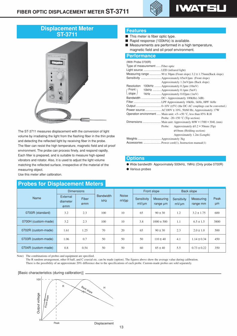
Displacement MeterST-3711
The ST-3711 measures displacement with the conversion of light
volume by irradiating the light from the flashing fiber in the thin probe
and detecting the reflected light by receiving fiber in the probe.
The fiber can resist the high temperature, magnetic field and oil proof
environment. The probe can process finely, and respond rapidly.
Each filter is prepared, and is suitable to measure high-speed
vibrators and rotator. Also, it is used to adjust the light volume
matching the reflected surface, irrespective of the material of the
measuring object.
Use this meter after calibration.
Note) The combinations of probes and equipment are specified.The R random arrangement, other H half, and C coaxial etc. can be made (option). The figures above show the average value during calibration.There is the possibility of an approximate 20% difference due to the specifications of each probe. Custom-made probes are sold separately.
Probes for Displacement Meters
Name
Dimensions Front slope Back slope
Peak
µm
External
diameter
ømm
Fiber
ømm
Sensitivity
mV/µm
Measuring
range µmSensitivity
mV/µm
Measuring
range mm
3.2 2.3 100 10 65 90 ± 30 1.2 3.2 ± 1.75 600
3.2 2.3 100 10 3.8 1000 ± 500 1.1 6.5 ± 1.5 3800
1.61 1.25 70 20 65 90 ± 30 2.3 2.0 ± 1.0 500
1.06 0.7 50 50 50 110 ± 40 4.1 1.14 ± 0.34 450
0.8 0.54 50 50 60 85 ± 40 5.5 0.73 ± 0.22 350
Noise
mVppBandwidth
kHz
0700R (standard)
0700H (custom-made)
0702R (custom-made)
0703R (custom-made)
0704R (custom-made)
[Basic characteristics (during calibration)]
Features This meter is fiber optic type. Rapid response (100kHz) is available. Measurements are performed in a high temperature,
magnetic field and oil proof environment.
Performance
Options Wide bandwidth Approximately 500kHz, 1MHz (Only probe 0700R)
Various probes
(With Probe 0700R)Type of measurement ......Light source .....................Measuring range ..............Sensitivity ........................
Resolution 100kHz ........10kHz ..........1kHz ............
Bandwidth ........................Filter .................................Output ..............................Power source ...................Operation environment .....
Dimensions ......................
Weights ............................Accessories .....................
Fiber opticLED (infrared light)90 ± 30µm (Front slope) 3.2 ± 1.75mm(Back slope)Approximately 65mV/µm (Front slope)Approximately 1.2mV/µm (Back slope)Approximately 0.2µm (10mV)Approximately 0.1µm (5mV)Approximately 0.02µm (1mV)DC~ Approximately 100kHz(-3dB)LPF Approximately 10kHz, 1kHz, HPF 1kHz0~10V (±5V) (the DC-AC couplings can be converted.)AC100V ± 10%, 50/60 Hz, Approximately 17WMain unit: +5~+50 ˚C, less than 85% R.HProbe: -20~150 ˚C (Tip section)Main unit: Approximately 80W × 170H × 304L (mm)
Probe: Approximately ø3.2 × 50mm (Tip)
ø10mm (Holding section)Approximately 1.2m (Length)
Approximately 3kgPower cord(1), Instruction manual(1)
Frontslope
14
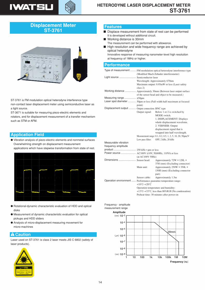
ST-3761 is FM modulation optical heterodyne interference type
non-contact laser displacement meter using semiconductive laser as
a light source.
ST-3671 is suitable for measuring piezo-electric elements and
rotators, and for displacement measurement of a transfer mechanism
such as STM or AFM.
Application Field Vibration analysis of piezo-electric elements and nonmetal surfaces
Overwhelming strength on displacement measurement
applications which have stepwise transformation from state of rest.
Rotational-dynamic characteristic evaluation of HDD and optical
disks
Measurement of dynamic characteristic evaluation for optical
pickups and HDD sliders
Analysis of micro-displacement measuring movement for
micro-machines
HETERODYNE LASER DISPLACEMENT METER ST-3761
Features Displace measurement from state of rest can be performed
It is developed without additional circuit. Working distance is 30mm
The measurement can be performed with allowance. High resolution and wide frequency range are achieved by
optical heterodyneInnovative response of measuring nanometer-level high resolution
at frequency of 1MHz or higher.
Type of measurement ........
Light source .......................
Working distance ...............
Measuring range ................Laser spot diameter ...........
Displacement output ..........
Measurable vibrationfrequency amplitudeproduct ...............................Power source .....................
Dimensions ........................
Operation environment ......
Frequency - amplitudemeasurement range
FM modulation optical heterodyne interference type(Modified Mach Zehnder interferometer)Semiconductor laserWavelength: Approximately 670nmMaximum output: 0.95mW or less (Laser safetyclass 2)Approximately 30mm (Between laser output surfaceof the sensor head and object to be measured.)±50µm50µm or less (Full width half maximum at focusedpoint)Output connection: BNC typeOutput signal: Below 1 or 2 is switched by
MODE switch.1. DISPLACEMENT: Displayswhole displacement waveform.2. VERNIER: Outputdisplacement signal that iswrapped into half wavelength.
Measurement range: 0.1, 0.2, 0.5, 1, 2, 5, 10, 20, 50µm/VLow pass filter: OFF, 2 kHz, 20 kHz
250 kHz • µm or lessAC100V ±10V, 50/60Hz, 110VA or less(at AC100V 50Hz)Sensor head: Approximately 72W × 128L ×
37H (mm) (Excluding connector)Main unit: Approximately 250W × 350L ×
150H (mm) (Excluding connectorpart)
Sensor cable: Approximately 1.5mPerformance guarantee temperature range:+18˚C~+28˚COperation temperature and humidity:+13˚C~+33˚C, less than 80%R.H (No condensation)Preheat time: 30 minutes after power-on
Performance
Displacement MeterST-3761
CautionLaser used on ST-3761 is class 2 laser meets JIS C 6802 (safety of
laser products).
Amplitude
Frequency

15
Gap Adjuster GA-202 Standard Fixture
Fixture for Capacitive Displacement Meter
ANGLEVEL METER AL-12
Anglevel MeterAL-12
The AL-12 is a level gauge measuring verticalness, horizontal
levelness, and angle of inclination.
Application Efficient for work inspection and adjustment in architectural work. Efficient for various type of civil engineering works. Most suitable
for levee construction, drain ditch construction, and piping work. The height of buildings or utility poles can be found from the
attached numerical table using measured elevation angle anddistance.
Suitable for setting equipments and shortwave antennas, andfacility maintenance equipment.
The meter can be set in any location on airplanes, marine vessels,or yachts as an inclination indicator. The meter can indicate limitangle of the resilience of ships.
Vehicles have safety angle of gradient. Setting the meter on thevehicle ensures safety of the vehicle.
Useful for angular measurement of sheet metal processing orvarious experiments at laboratories and schools.
When the meter is attached to a building on the cliff top, whetherthere is an increase on inclination of the building over the years ornot can be measured. Inclination of buildings around constructionsite and bridge beam can be monitored similarly.
By measuring elevation angle of building and cliffs, shaded area inwinter is estimated.
Useful for measuring inclination of buildings and utility poles atsome distance.
Suitable for do-it-yourself hobbies.
Examples of application
Features Easy to read vibration-free gauge pointer The angle can be read by setting the meter on the
measuring surface Measurement can be conducted when the meter is tilted
back and forth Due to non-weight design for the pointer, the meter has
easy to read long gauge pointer and high scale resolution Measurement is not influenced by normal temperature,
humidity, or wind The meter is inexpensive, compact, lightweight, easy to
carry, and durable for long time use Measurement can be conducted by just one person, or
even under the water The meter is made of acrylic resin and can be used for an
accessory at home
PerformanceMeasuring range ..............Accuracy ..........................Dimensions ......................Weight ..............................Temperature range ..........Minimum scale value .......
0~90˚, 50˚~0~50˚1% (Full scale)83W × 17L × 83H (mm)130 g-30˚C~+50˚C0.5˚
The gap adjuster fixes probes and measuring electrodes, and
finely-adjusts gap from the object using the microhead. It has a
magnetic stand.
Minimum scale value 0.002mm
Standard fixture for probes. (Example on use on page 4.)
It has a magnetic stand to use on the granite surface plate.
Can adjust the gap to XYZ.
Measuring heightA mirror is required.
Distance
Inclination of utility pole at some distance
Plumbing (inclination)
Measuring limit of shade area in winterA mirror is required.

IWATSU TEST INSTRUMENTS CORPORATION has been awarded the above International Standard ISO9001 and ISO 14001 certificates for quality control and environmental management.Certificate No. 961550:772520
This product is subject to the cargo (or technology)controls according to the Foreign Exchange and ForeignTrade Control Law. Export permission from the JapaneseGovernment is necessary to export this product.
The contents of this catalog may be altered without prior notice to improve products.
If you have any questions about IWATSU products, contact our sales department.
The contents of this catalog is correct as of January 1, 2006.
Distributor
8511-3091-2C.S(D)0601-827-2-00
SALES DEPT. : 7-41, 1-CHOME KUGAYAMA,SUGINAMI-KU, TOKYO, 168-8511 JAPANTEL : +81-3-5370-5483, FAX: +81-3-5370-5492Homepage : http://www.itl.iwatsu.co.jpE-mail Address : [email protected]