IWAKI Gas-Liquid Transfer Pump APN-085-W Instruction Manual · Read this manual before use of...
24
Read this manual before use of product APN-085-W Instruction Manual IWAKI Gas-Liquid Transfer Pump
Transcript of IWAKI Gas-Liquid Transfer Pump APN-085-W Instruction Manual · Read this manual before use of...

Read this manual before use of product
APN-085-WInstruction Manual
IWAKIGas-Liquid Transfer Pump

Thank you for selecting the IWAKI APN series gas-liquid transfer pump. This instruction manual deals with "Safety Instructions", "Outline", "Installation", "Operation" and "Maintenance" sections.Please read through this instruction manual to ensure the opti-mum performance, safety and service of your pump.
Important Instruction
WARNINGNonobservance or misapplication of the contents of “Warning” section could lead to a serious accident which may result in death.
CAUTIONNonobservance or misapplication of the contents of “Caution” section could lead to personal injury or property damage.
Types of SymbolsIndicates a prohibited action or procedure. Inside or near this cir-cle, a concrete and practical image of the activity to be avoided is depicted.
Indicates an important action or procedure which must be per-formed or carried out without fail. Failure to follow the instruc-tions herein can lead to malfunction or damage to the pump.
For the Safe and Correct Handling of the Pump
● "Safety Instruction" section deals with important details about handling of the product. Before use, read this section carefully for the prevention of personnel injury or property damage.
● Observe the instructions accompanied with "WARNING" or "CAUTION" in this manual. These instructions are very impor-tant for protecting pump users from dangerous situations.
● The symbols on this instruction manual have the following meanings:
For exportationTechnology related to the use of goods in this instruction manual falls in the category of technology contained in the Foreign Exchange Order Attachment, which includes complementary export control of technology. Please be reminded that export license, which is issued by the Ministry of Economy, Trade, and Industry could be required, when this is exported or provided to someone even in Japan.
Contents
Safety Instructions ··········································································1Outline 1. Unpacking & Inspection ·······································3
2. Operating principle ···············································33. Identification code ················································44. Specifications ························································45. Outer dimension ····················································56. Performance curve ················································57. Overview & Label ·················································68. Part names & Structure ········································6
Installation 1. Before installation ·················································82. Installation/Tubing/Electrical wiring ················· 10
Operation 1. Before operation ·················································· 122. Pump operation ··················································· 13
Maintenance 1. Troubleshooting ·················································· 152. Maintenance & Inspection ································· 153. Wear part replacement ········································ 17
This instruction manual should be kept on hand by the end user for quick reference.
Contact us or your nearest dealer if you have any questions.
- 1 -
Prohibited
Electrical shock
Prohibited
Prohibited
Prohibited
No remodeling
Caution
Caution
Wear protectors
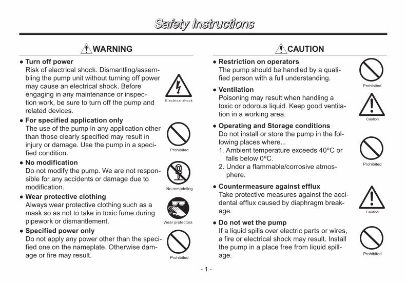
WARNING● Turn off power
Risk of electrical shock. Dismantling/assem-bling the pump unit without turning off power may cause an electrical shock. Before engaging in any maintenance or inspec-tion work, be sure to turn off the pump and related devices.
● For specified application only The use of the pump in any application other than those clearly specified may result in injury or damage. Use the pump in a speci-fied condition.
● No modification Do not modify the pump. We are not respon-sible for any accidents or damage due to modification.
● Wear protective clothing Always wear protective clothing such as a mask so as not to take in toxic fume during pipework or dismantlement.
● Specified power only Do not apply any power other than the speci-fied one on the nameplate. Otherwise dam-age or fire may result.
● Restriction on operators The pump should be handled by a quali-fied person with a full understanding.
● Ventilation Poisoning may result when handling a toxic or odorous liquid. Keep good ventila-tion in a working area.
● Operating and Storage conditions Do not install or store the pump in the fol-lowing places where...1. Ambient temperature exceeds 40ºC or
falls below 0ºC.2. Under a flammable/corrosive atmos-
phere.
● Countermeasure against effluxTake protective measures against the acci-dental efflux caused by diaphragm break-age.
● Do not wet the pump If a liquid spills over electric parts or wires, a fire or electrical shock may result. Install the pump in a place free from liquid spill-age.
CAUTION
Prohibited
Safety Instructions

● Install an earth leakage breaker Risk of electrical shock. Do not use the pump without an earth leakage breaker. Purchase separately.
● Damaged power cable Do not use any damaged power cable for the prevention of a fire or electrical shock. The cable is not replaceable, so that the whole pump unit needs to be replaced when the cable is damaged.
● Pump disposal Dispose of any used or damaged pump in accordance with local laws and regulations ( Consult a licensed industrial waste prod-ucts disposing company.).
● Earth connection Always earth the pump in order to reduce the risk of electrical shock.
- 2 -
Prohibited
Electrical shock
Electrical shock
Prohibited
CAUTION CAUTION
Safety Instructions
● Damaged pumps Do not use any damaged pump. Using a damaged pump may lead to an electric leak or shock.
● Stop operation Finding any abnormality, stop operation immediately and inspect/solve problems.
● Pump dismantlement Dismantlement should be carried out within the descriptions in this instruction.
● Do not damage a power cable Risk of fire or electrical shock. Do not scratch, modify, or pull a power cable. The cable can also be damaged when it is heat-ed or loaded with a heavy thing.
● Do not place the pump close to water The pump is not dust-/water-proof construc-tion. The use of the pump in a humid place or a place where the pump can get wet may result in electrical shock or short-circuit.
Grounding
Electrical shock

2. Operating principleThe APN-085-W is a gas-liquid transfer pump with a small size diaphragm and special valves, and is designed for built-in application.The rotary motion of the motor is converted via a con-necting rod to the reciprocation of the diaphragm in the pump chamber, where the mixture of gas and liquid is transferred from the inlet to outlet.
- 3 -
Before use, check the specification, limitation and hazardous nature of the pump.
1. Unpacking & Inspection On unpacking the product, check the following points. If you find any problems, contact your nearest distributor.
1. Check the information on the nameplate to see that the product is delivered as per order.
2. Check for transit damage, deformation, and loose bolts.
Outline
Flow rateDischarge pressure
Power voltage
Manufacturing No.
OUTINOUTIN
Pump head(Pump chamber)
Diaphragm
Connecting rod
Valve
: Diaphragm reciprocation: Flow direction
Discharge process Suction process

- 4 -
3. Identification code
APN - P 085 E X - E4 - W 02 a b c d e f g
a. Pump headNo code : SingleP : Twin parallel
b. Series name
c. Diaphragm materialsE : EPDMV : FKM
d. Pump connectionX : Thread connection (Rc1/8)
e. Rated voltageE4 : 220V/240VAC with a Cabtyre cable
f. Gas-liquid transfer type
g. Special specificationNo code : Standard01-99 : Special design
Outline4. Specifications■ Pump 50Hz, 220/240V
TypeMax. air
flow(L/min)
Max. dis-charge
pressure(MPa)
Max. vacuum
(kPa)
Motor Connec-tion Weight
(kg)
Lowest startingtemp.(°C)
Power con.(W)
Output(W)
Rated current
(A)Thread
APN-085E3
0.05
34.66
48 20 0.22 Rc1/82.5
5APN-085V 37.33
APN-P085E5
34.662.8
APN-P085V 37.33
NOTE1. Observe the maximum discharge pressure of 0.05MPa.
NOTE2. Allowable gas temperature range is 0-40°C.NOTE3. Allowable liquid temperature range is 5-40°C.NOTE4. Allowable ambient temperature range is 0-40°C.
Observe the lowest starting temperature at the start of operation.
NOTE5. Both the inlet and outlet of the pump are Rc1/8 female thread connections (JIS taper pipe thread).
■ Wet end materialParts Model V EPump head GFRPPDiaphragm
FKM EPDMValveValve seat GFRPPGasket FKM EPDM
GFRPP : Glass fiber reinforced polypropyleneFKM : Fluorine-contained rubberEPDM : Ethylene propylene diene monomer

6. Performance curve■ APN-085-W (Single)
■ APN-P085-W (Twin parallel)
- 5 -
Outline
82.4ø71
13 13
(126
)
5
(174)
2-Rc1/8
2-Rc1/82-Rc1/8
(198)
(190) 13 13
ø7182.4
(126
)
5
0.05
34.66APN-085E
21.33
7.99
101.32
47.99
61.32
74.66
87.99
0
1 2 3 4 5 6
APN-085V
Discharge pressure(MPa)
AIR FLOW(L/min)
Vacuum pressure(kPa) [abs]
50Hz
7.99
47.99
21.33
34.66
74.66
87.99
61.32
101.32 0
0.05
1 2 3 4 5 6
APN-P085E
APN-P085V
Discharge pressure(MPa)
AIR FLOW(L/min)
Vacuum pressure(kPa) [abs]
50Hz
5. Outer dimension■ APN-085-W (Single)
■ APN-P085-W (Twin parallel)

- 6 -
Outline8. Part names & Structure■ APN-085-W
No. Part names Q'ty No. Part names Q'ty1 Pump head 1 20 Bracket 12 Valve 2 40 Motor 13 Valve seat 1 46 Capacitor 14 Diaphragm 1 62 Small screw 419 Connecting rod unit 1 set 79 Plate washer 1
38 Gasket 2
7. Overview & LabelThe illustration below shows an APN-085-W single head type.
Pump head
Name plateModel and MFG. No.(Production number) are described.
Pump body(Driven unit)An installation location should be free from liq-uid spillage.
BaseAnchor the pump with M5 screws.
Outlet Inlet
Motor
Lead wireConnect to corre-sponding terminals through crimp con-nectors.
Caution label
Earth terminalBe sure to earth the pump.
6240 4 3 2 146
20
19
79
38

- 7 -
Outline
46
20
621
19
40 4 3 2 38
79
■ APN-P085-W
No. Part names Q'ty No. Part names Q'ty1 Pump head 2 20 Bracket 22 Valve 4 40 Motor 13 Valve seat 2 46 Capacitor 14 Diaphragm 2 62 Small screw 819 Connecting rod unit 2 set 79 Plate washer 2
38 Gasket 4
- 8 -
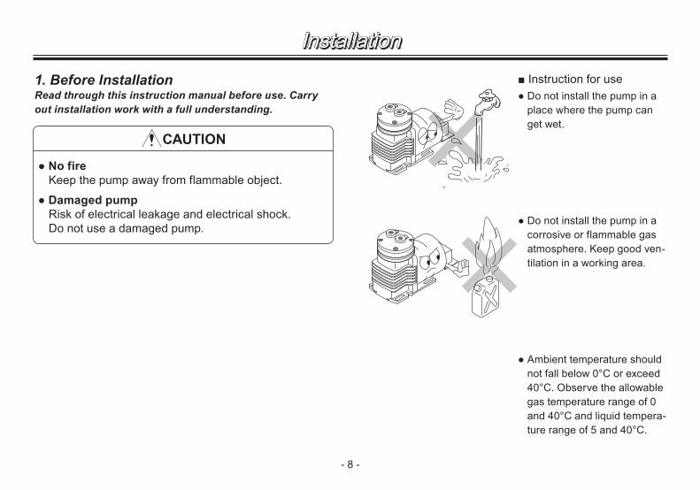
■ Instruction for use● Do not install the pump in a
place where the pump can get wet.
● Do not install the pump in a corrosive or flammable gas atmosphere. Keep good ven-tilation in a working area.
● Ambient temperature should not fall below 0°C or exceed 40°C. Observe the allowable gas temperature range of 0 and 40°C and liquid tempera-ture range of 5 and 40°C.
1. Before InstallationRead through this instruction manual before use. Carry out installation work with a full understanding.
● No fireKeep the pump away from flammable object.
● Damaged pump Risk of electrical leakage and electrical shock.Do not use a damaged pump.
CAUTION
Installation

- 9 -
Installation● Observe the rated voltage
specified on the name plate. Applying any voltage than the rated one may result in failure.
● Surface temperature may rise high in operation but it dose not mean failure.Do not touch the pump body directly or place the objects which may be deformed by heat close to the pump.
● Do not use the pump in a dusty place. Be sure to provide the inlet with a filter to prevent foreign mat-ters from getting into the pump. Otherwise, the pump performance may reduce or the lives of valves and diaphragm may remarkably shorten.
● Do not tube two or more pumps in series. It may pre-vent the motor from starting and lead to a burn out.
● The APN-P085-W is designed to be tubed in par-allel only. Do not tube it in series.
Risk of burn
Provide a filterOUTIN
OUTIN
IN
IN
OUT
OUT
INOUT
OUT
IN
Parallel
Series
?V

- 10 -
Installation2. Installation/ Tubing/ Electrical wiring
2.1 Installation
1. Do not expose the pump to direct sunlight, vibration and wind & rain.
2. Keep good ventilation. The pump should always be free from the possibility of getting wet.
3. Ambient temperature should not fall below 0°C or exceed 40°C. Observe the allowable maximum ambient humidity of 90%RH.
4. Install the pump in a clear and level place.Select a convenient place for maintenance and inspec-tion.
5. Pump fixationSet the pump baseplate on a con-crete foundation and fasten cor-rosion-resistant M5 screws tightly to prevent the pump from vibrating during operation.CAUTION
Do not install the pump on a wobbly pedestal.
2.2 Tubing1. The short tubing with the minimum bends is optimal to
reduce resistance.
2. Avoid sharp turns or bends.CAUTION
Do not have tubing bent or pressed. Otherwise, the tube end may break.
3. Tubes and fittings Provide tube fittings to the threaded inlet and outlet (Rc1/8) of the pump. Use chemically-resistant tubes or tempera-ture-/pressure-resistant braided tubes as necessary. Cut the tube ends and have them flat before insertion.
Stop working upon sensing danger or abnormality.
WARNING

- 11 -
Installation4. Tube size
For liquid transfer, a suction line bore should be ø4mm or less. Otherwise, the motor is locked by overfeeding.A discharge line bore should be ø8mm or more.CAUTION
Use of a large tube bears the risk of coming off, causing an air and a liquid leak.
5. Valve mountingInstall a ball valve in a suction line for adjusting an air/liquid flow or the degree of vacuum and in a discharge line for shutoff or the convenience of maintenance.
6. Tube and fitting connection Wrap a sealing tape to the thread of tube fittings and screw them into the inlet and outlet of the pump. And then fit and slide tubes down onto the fittings as far as they will go.
NOTE: If suction line connection is imperfect, the pump sucks air and it prevents the pump from bringing out full per-formance.
2.3 Electrical wiringElectrical wiring must be done by a qualified person who has a full knowledge of safety. We are not responsible for personal injury or property damage due to nonobservance of this warn-ing. Contact us or your nearest distributor for wiring as neces-sary.
■ Before wiring1. Confirm that power is disconnected before work.2. Wiring work should be done in accordance with relevant
electric work requirements. Use the recommended wiring accessories.
3. Observe the rated voltage specified on the name plate.4. Earth the pump through the earth terminal.5. Install the leakage breaker as necessary. When it has func-
tioned, turn off power and check/solve problems to restore a normal state.

- 12 -
● Dropping or subjecting the pump to strong impact, fail-ure may result.Handle the pump with care.
● The pump can not start with full discharge/suction pres-sure or full liquid. Remove pressure or liquid before operation.
● After a long period of stop-page, pump performance at the beginning of operation becomes occasionally unsta-ble. In this case, warm the pump up for 10 minutes with no discharge line pressure.
● Always use a suction valve to adjust an air/liquid flow.
● If the compressed air or liquid (higher pressure than atmospheric pres-sure) is transferred to the pump, sharp deterioration to the lives of the valves, diaphragm and bearing may result. The suction line pressure should be equal to atmospheric pressure or vacuum pressure.
● Do not use solvents such as benzine, alcohol, thinner for maintenance or cleaning, otherwise a coat discolours or comes off.
1. Before operation
Suction pressure
Suction valve
No load operation
Keep a discharge valve full open.
↓
↓
Suction valve
Do not apply suction line pressure
↓
Operation

- 13 -
2. Pump operation■ Start-up1. Before pump operation, check
that each tube connection is secured.
2. Check that a suction tube is connected to the inlet and a dis-charge tube is connected to the outlet.CAUTION
If a suction line and a discharge line are connected the other way around, pumping process is inverted.
3. Check that the pump is firmly fixed on a mounting position.
■ OperationOperate the pump according to the following steps.
No. Procedure Contents
1 Check tubing, wir-ing and voltage.
● Check installation, tubing and wiring are properly done and wiring system is fused.
● Check the spec label to see if power supply voltage is correct.
2 Open valves. ● Fully open both discharge and suction lines.
3 Supply power to the pump.
● After checking the items 1 and 2. Turn on power and start the pump.
● Smooth starting may not be obtained when ambient temperature is 10ºC or below. In this case, run the pump with no discharge line pressure for a few minutes to warm it up.
● Smooth starting may not be obtained when the pump chamber is filled with liquid. Get rid off liquid before operation.
4 Adjust air flow.
● After the pump has reached a speci-fied stroke rate, initiate full scale operation.
● Always adjust an air flow by a suction valve.
5Points to be checked during operation
● After starting, check a pressure gauge to see if suction and discharge line pres-sure are correct and an air flow meter to see if the specified air flow is obtained.
● Keep a suction line pressure at or below atmospheric pressure.
● In case electric power has failed while the pump is running, switch off main power. Otherwise, the motor may not re-start or may burn out depending on a line pressure at the time of power recovery.
Operation

- 14 -
Operation■ Stop and StorageBefore a long period of stoppage (1 week or more)...
● Release pressure and turn off main power.● Make sure both supply air and gas are stopped.
Before resuming operation...● Operation may occasionally be upset in the beginning. In
this case warm up the pump under no load operation in advance.
● Follow the "■ Operation" table to resume operation.

- 15 -
1. Trouble shootingTurn off power on sensing danger and check the follow-ing. In case trouble can not be solved, contact us or your nearest distributor.
Phenomenon
Causes
Pum
p do
es n
ot ru
n.P
ump
stop
s ru
nnin
g.Po
or ai
r flow
or di
scha
rge p
ress
ure
Pum
p m
akes
noi
se.
Measures
No power distribution Check wiring.Motor trouble (disconnection or capacitor failure) Replace the motor.*Wrong tubing or poor connection Check and fix tubing.Pump head mounting screws are loose. Tighten the screws.Diaphragm insertion is loose. Tighten diaphragm.Diaphragm is damaged. Replace diaphragm.Filter is clogged. Remove foreign matters.Valves are worn. Replace valves.Motor-Bracket fixing screws are loose. Secure them.Eccentric shaft has worn. Replace the connecting rod.*Connecting rod bearing has worn. Replace the connecting rod.*Motor bearing has worn. Replace the motor.*Voltage reduction Increase voltage to the rated level.Higher suction pressure than atmospheric Reduce suction pressure.Condensation in the pump head Dry up the pump.
Contact us for the measures marked with *.
2. Maintenance & InspectionHandling of the pump, maintenance and inspection should be carried out within this instruction manual. Do not handle the pump beyond the descriptions in this manual.We are not responsible for personal injury or property dam-age due to nonobservance of this warning. Contact us or your nearest distributor as necessary.
■ Daily inspectionPay attention to the following items during operation. Stop operation on sensing danger and solve problems on the trou-ble shooting section. If pump performance has remarkably reduced, replace wear parts.
No. Check that... Measure
1 pump operation is normal.
• Apply correct voltage and amperage.
• Adjust discharge/suction pressure.
2there is no noise or vibration problem.
• Unusual noise/vibration may occur when pump operation is not normal.
3there is no air leak or air ingress from pump parts and tubing connections.
• Retighten connections.
Maintenance

- 16 -
■ Wear partsIf pump performance has remarkably reduced, replace dia-phragms and valves with new ones. Wear part duration varies with the pressure, temperature and characteristics of gas/liquid. The estimated life below is calculated based on continu-ous operation with clean water in a room temperature range of 0-40°C.
Application Load rangeEstimated life
Valve Diaphragm GasketGas transfer All range 8000hr 8000hr 8000hr
Liquid transfer No load 4000hr 4000hr 4000hr* The above lives are reference values and not warranted.
■ CleaningTurn off power and wait until the pump has cooled down. Then clean off the surface of the pump with a wet cloth. Use a neu-tral detergent for greasy dirt as necessary and dry it with a dry cloth.Check the pump surface has dried up before operation.
CAUTIONRisk of electrical shock. Do not wet electric parts or wir-ing.
■ StorageProtect the pump from dust during storage.Do not store the pump in the following places where...• Ambient temperature falls below 0°C or exceeds 40°C.• Under a flammable or corrosive atmosphere.• Under heavy dust or high humidity.• Under direct sunlight or wind & rain.• Under vibration.
Maintenance

- 17 -
Maintenance3. Wear part replacementFor a long period of operation wear parts need to be replaced periodically.
CAUTION
● Turn off power before workRisk of electrical shock. Be sure to turn off power to stop the pump and related devices before work.
● Do not touch the pump or pipe with bare bandsRisk of burning. The surface temperature of the pump or pipe gets high in or right after operation.
● Wear protective clothing Always wear protective clothing such as a mask so as not to take in toxic fume during pipework or dismantlement.
See page 6 "8. Part names & Structure" as necessary.
■ Diaphragm replacement1. Unscrew the pump head fix-
ing screws and take out the pump head, valves, gaskets and valve seat.
2. Turn the diaphragm anti-clockwise so as to detach it from the rod.
3. Mount a new diaphragm into the rod and fasten as far as it will rotate.
4. Push down the diaphragm until it bottoms out and then reassemble and secure the above parts onto the bracket with the screws by 1.37N•m.
Screw
Pump head
Gasket
Bracket
Con rod
Valve
Valve seat
Plate washer
Diaphragm

- 18 -
Maintenance■ Valve & Gasket replace-
ment1. Unscrew the pump head
fixing screws and dismantle the pump head unit.
2. Replace old valves and gas-kets with new ones and then reassemble the pump head unit.
3. Supply air into the pump head unit through the inlet and check the air is dis-charged through the outlet.
4. Push down the diaphragm until it bottoms out and then secure the unit onto the bracket with the screws by 1.37N•m.
IN OUTPump head
Gasket
Valve
Valve seat
NOTE1. For the APN-P085 twin parallel type, finish either pump head first and then start with the other.
NOTE2. Do not loosen the motor-bracket fixing screws during maintenance work.
NOTE3. Contact your nearest distributor for the replacement of the connecting rod and the motor.

- 19 -

- 20 -

- 21 -

T751 '10/12
( )Country codes
IWAKI CO.,LTD. 6-6 Kanda-Sudacho 2-chome Chiyoda-ku Tokyo 101-8558 JapanTEL:(81)3 3254 2935 FAX:3 3252 8892(http://www.iwakipumps.jp)
Australia IWAKI Pumps Australia Pty. Ltd. TEL : (61)2 9899 2411 FAX : 2 9899 2421 Italy IWAKI Italia S.R.L. TEL : (39)0444 371115 FAX : 0444 335350Austria IWAKI (Austria) GmbH TEL : (43)2236 33469 FAX : 2236 33469 Korea IWAKI Korea Co.,Ltd. TEL : (82)2 2630 4800 FAX : 2 2630 4801Belgium IWAKI Belgium n.v. TEL : (32)1367 0200 FAX : 1367 2030 Malaysia IWAKIm Sdn. Bhd. TEL : (60)3 7803 8807 FAX : 3 7803 4800China IWAKI Pumps (Shanghai) Co., Ltd. TEL : (86)21 6272 7502 FAX : 21 6272 6929 Norway IWAKI Norge AS TEL : (47)66 81 16 60 FAX : 66 81 16 61China IWAKI Pumps (Guandong) Co., Ltd. TEL : (86)750 3866228 FAX : 750 3866278 Singapore IWAKI Singapore Pte. Ltd. TEL : (65)6316 2028 FAX : 6316 3221China GFTZ IWAKI Engineering & Trading (Guangzhou) TEL : (86)20 8435 0603 FAX : 20 8435 9181 Spain IWAKI Iberica Pumps, S.A. TEL : (34)943 630030 FAX : 943 628799China GFTZ IWAKI Engineering & Trading (Beijing) TEL : (86)10 6442 7713 FAX : 10 6442 7712 Sweden IWAKI Sverige AB TEL : (46)8 511 72900 FAX : 8 511 72922Denmark IWAKI Nordic A/S TEL : (45)48 24 2345 FAX : 48 24 2346 Switzerland IWAKI (Schweiz) AG TEL : (41)26 674 9300 FAX : 26 674 9302Finland IWAKI Suomi Oy TEL : (358)9 2745810 FAX : 9 2742715 Taiwan IWAKI Pumps Taiwan Co., Ltd. TEL : (886)2 8227 6900 FAX : 2 8227 6818France IWAKI France S.A. TEL : (33)1 69 63 33 70 FAX : 1 64 49 92 73 Taiwan IWAKI Pumps Taiwan (Hsin-chu) Co., Ltd. TEL : (886)3 573 5797 FAX : (886)3 573 5798Germany IWAKI EUROPE GmbH TEL : (49)2154 9254 0 FAX : 2154 9254 48 Thailand IWAKI (Thailand) Co.,Ltd. TEL : (66)2 322 2471 FAX : 2 322 2477Holland IWAKI EUROPE NL Branch TEL : (31)547 293 160 FAX : 547 292 332 U.K. IWAKI Pumps (UK) LTD. TEL : (44)1743 231363 FAX : 1743 366507Hong Kong IWAKI Pumps Co., Ltd. TEL : (852)2 607 1168 FAX : 2 607 1000 U.S.A. IWAKI AMERICA Inc. TEL : (1)508 429 1440 FAX : 508 429 1386Indonesia IWAKI Singapore (Indonesia Branch) TEL : (62)21 690 6606 FAX : 21 690 6612 Vietnam IWAKI pumps Vietnam Co.,Ltd. TEL : (84)613 933456 FAX : 613 933399