IV Semester Diploma in Civil Engineering / Civil (Rural ...gpmuz.bih.nic.in/syllabus/4th sem...
22
STATE BOARD OF TECHNICAL EDUCATION, BIHAR Scheme of Teaching and Examinations for IV Semester Diploma in Civil Engineering / Civil (Rural) Engineering ( Effective from Session 2016-17 Batch ) THEORY Sr. No . SUBJECT SUBJECT CODE TEACHING SCHEME EXAMINATION-SCHEME Periods per Week Hours of Exam. Teacher's Assessment (TA) Marks A Class Test (CT) Marks B End Semester Exam.(ESE) Marks C Total Marks (A+B+C) Pass Marks ESE Pass Marks in the Subject Credits 1. Advance Surveying 1615401 02 03 10 20 70 100 28 40 02 2. Mechanics of Structures 1615402 03 03 10 20 70 100 28 40 03 3. Geo Technical Engineering 1615403 03 03 10 20 70 100 28 40 03 4. Transportation Engineering 1615404 03 03 10 20 70 100 28 40 03 5. Hydraulics 1615405 03 03 10 20 70 100 28 40 03 Total :- 14 350 500 PRACTICAL Sr. No. SUBJECT SUBJECT CODE TEACHING SCHEME EXAMINATION-SCHEME Periods per Week Hours of Exam. Practical (ESE) Total Marks (A+B) Pass Marks in the Subject Credits Internal(A) External(B) 6. Advance Surveying Lab 1615406 04 03 15 35 50 20 02 7. Mechanics of Structures Lab 1615407 03 03 15 35 50 20 01 8. Geo Technical Engineering Lab 1615408 02 03 15 35 50 20 01 9. Hydraulics Lab 1615409 04 03 15 35 50 20 02 Total :- 13 200 TERM WORK Sr. No. SUBJECT SUBJECT CODE TEACHING SCHEME EXAMINATION-SCHEME Periods per Week Marks of Internal Examiner (X) Marks of External Examiner (Y) Total Marks (X+Y) Pass Marks in the Subject Credits 10. Professional Practices-IV (TW) 1625410 03 07 18 25 10 02 11. Computer Aided Drawing (TW) 1615411 03 07 18 25 10 02 Total :- 06 50 Total Periods per week Each of duration One Hour 33 Total Marks = 750 24
Transcript of IV Semester Diploma in Civil Engineering / Civil (Rural ...gpmuz.bih.nic.in/syllabus/4th sem...

STATE BOARD OF TECHNICAL EDUCATION, BIHAR Scheme of Teaching and Examinations for
IV Semester Diploma in Civil Engineering / Civil (Rural) Engineering
( Effective from Session 2016-17 Batch )
THEORY
Sr.
No
.
SUBJECT SUBJECT
CODE
TEACHING
SCHEME
EXAMINATION-SCHEME
Periods per
Week
Hours
of
Exam.
Teacher's
Assessment
(TA)
Marks
A
Class
Test
(CT)
Marks
B
End Semester
Exam.(ESE)
Marks
C
Total
Marks
(A+B+C)
Pass
Marks
ESE
Pass
Marks
in the
Subject
Credits
1. Advance
Surveying 1615401 02 03 10 20 70 100 28 40 02
2. Mechanics of
Structures 1615402 03 03 10 20 70 100 28 40 03
3. Geo Technical
Engineering 1615403 03 03 10 20 70 100 28 40 03
4. Transportation
Engineering 1615404 03 03 10 20 70 100 28 40 03
5. Hydraulics 1615405 03 03 10 20 70 100 28 40 03
Total :- 14 350 500
PRACTICAL
Sr.
No. SUBJECT
SUBJECT
CODE
TEACHING
SCHEME
EXAMINATION-SCHEME
Periods per
Week
Hours of
Exam.
Practical (ESE) Total
Marks
(A+B)
Pass Marks
in the
Subject
Credits
Internal(A) External(B)
6. Advance
Surveying Lab 1615406 04 03 15 35 50 20 02
7. Mechanics of
Structures Lab 1615407 03 03 15 35 50 20 01
8. Geo Technical
Engineering Lab 1615408 02 03 15 35 50 20 01
9. Hydraulics Lab 1615409 04 03 15 35 50 20 02
Total :- 13 200
TERM WORK
Sr.
No. SUBJECT
SUBJECT
CODE
TEACHING
SCHEME
EXAMINATION-SCHEME
Periods per
Week
Marks of
Internal
Examiner
(X)
Marks of
External
Examiner
(Y)
Total
Marks
(X+Y)
Pass Marks
in the
Subject
Credits
10. Professional Practices-IV
(TW) 1625410 03 07 18 25 10 02
11. Computer Aided Drawing
(TW) 1615411 03 07 18 25 10 02
Total :- 06 50
Total Periods per week Each of duration One Hour 33 Total Marks = 750 24

ADVANCE SURVEYING (CIVIL ENGINEERING GROUP)
Subject Code
1615401
Theory Credits
No. of Periods Per Week Full Marks : 100 02
L T P/S ESE : 70
02 — — TA : 10
— — — CT : 20
CONTENTS : THEORY Name of the Topic Hrs/week Marks
Unit -1 Plane Table Survey
1.1 Principles of plane table survey. Accessories required
1.2 Setting out of plane table , Levelling , Centering and orientation.
1.3 Methods of plane table surveying – Radiation, Intersection,
and Traversing.
1.4 Merits and Demerits of plane table Surveying. situations
where plane table survey is used.
1.5 Use of Telescopic Alidade.
05
10
Unit -2 Theodolite Survey
2.1 Components of Transit Theodolite and Their functions. Technical
terms used. Temporary adjustments of Transit Theodolite.
Swinging the telescope, Transiting, Changing the face.
2.2 Measurement of Horizontal angle, method of Repetition,
errors eliminated by method of repetition.
2.3 Measurement of Deflection angle.
2.4 Measurement of Vertical angle.
2.5 Measurement of magnetic bearing of a line by Theodolite .
2.6 Prolonging a Straight line.
2.7 Sources of errors in Theodolite Surveying. 2.8 Permanent adjustment of transit Theodolite ( only
relationship of different axes of Theodolite.).
2.9 Traversing with Theodolite – Method of included angles,
locating details, checks in closed traverse, Calculation of
bearings from angles.
2.10 Traverse Computation - Latitude, Departure Consecutive
Co-ordinates error of Closure, Distribution of a angular
error, balancing the traverse by Bodwitch rule and Transit
Rule, Gale’s traverse table .simple problems on above topic.
10
20
Unit – 3 Tacheometric Survey
3.1 Principle of Tacheometry.
3.2 Essential requirements of Tachometer.
3.3 Use of Theodolite as a Tacheometer with staff held in
vertical and fixed hair method (No derivation).
3.4 Determination of tacheometric constants, simple
numerical problems on above topics.
06
12

Unit – 4 Curves
4.1 Types of curves used in road and railway alignments.
Notations of simple circular curve.
Designation of curve by radius and degree of curves.
4.2 Method of Setting out curve by offset from Long chord
method and Rankine’s method of deflection angles.Simple
Numerical problems on above topics.
05
10
Unit – 5 Advanced Survey Equipments
5.1 Construction and use of one second Micro Optic Theodolite,
Electronic Digital Theodolite. Features of Electronic
Theodolite
5.2 Principle of E.D.M, Components of E.D.M and their
functions, use of E.D.M.
5.3 Total station
12
12
Unit – 6 Aerial Survey and Remote sensing
6.1 Aerial Survey Introductions, definition, Aerial photograph.
6.2 Remote Sensing – Introduction, Electro-Magnetic Energy ,
Remote sensing system- Passive system , Active system.
Applications – mineral, land use / Land cover, Natural
Hazards and Environmental engineering system.
04
06
Total 42 70
Text /Reference Books:-
Titles of the Book Name of Authors Name of the Publisher
Surveying and Levelling N N Basak Tata Mc Graw-Hill
Surveying and Levelling Part I
and II
T .P. Kanetkar & S. V, Kulkarni
PUNE VIDHYARTHI GRIHA Prakashan
Surveying and Levelling Vol. I
and II
Dr. B. C. Punmiya
Laxmi Publication
Text book of Surveying
S.K.Husain, M.S. Nagaraj
S. Chand and company
Surveying and
Levelling Vol. I and II
S. K. Duggal
TATA MC GRAW-HILL
Plane Surveying
A.M.Chandra
NEW AGE
INTERNATIONAL
Advance Surveying Nishit Sinha Foundation Publishing

MECHANICS OF STRUCTURES (CIVIL ENGINEERING GROUP)
Subject Code
1615402
Theory Credits
No. of Periods Per Week Full Marks : 100 03
L T P/S ESE : 70
03 — — TA : 10
— — — CT : 20
Contents : Theory
Name of the Topic Hrs/week Marks
Unit -1 Stress & Strain 1.1 Definition of rigid body, plastic body, mechanical properties of
metal such as elasticity & elastic limit. 1.2 Definition of stress, strain, modulus of elasticity, S. I. Unit.
Classification of stress, strain, Sign convention. Stress, strain curve for mild steel and HYSD bar , yield stress/ proof stress, Ultimate stress, breaking stress and percentage elongation.
1.3 Deformation of body due to axial load. Deformation of a Body subjected to axial forces. Deformation of body of stepped c/s due to axial load, max. stress and min. stress induced. Stresses in bars of composite section & deformation.
1.4 Shear stress, shear strain & modulus of rigidity, complementary shear stress, state of simple shear, punching shear.
10
10
Unit -2 Elastic Constants & Principal Stresses 2.1 Definition of lateral strain, Poisson’s ratio, Change in lateral
dimensions 2.2 Volumetric strain due to uni-axial force and change in volume 2.3 Biaxial and tri-axial stresses and volumetric strain &
change in volume 2.4 Definition of bulk modulus, volumetric strain. 2.5 Relation between modulus of elasticity, modulus of rigidity
and bulk modulus. 2.6 Definition of principal planes & principal stresses 2.7 Principal planes & stress due to bi-axial stress system & due
to state of simple shear. (Analytical method only)
08 10
Unit – 3 Shear Force And Bending Moment : 3.1 Types of beams - cantilever, simply supported, fixed and
continuous beams, types of loading- point load, uniformly distributed load, support reactions for determinate structures
3.2 Concept of shear force and bending moment, sign convention. Relation between bending moment, shear force and rate of loading
3.3 Shear force and bending moment diagrams for simply supported beams, overhanging beams and cantilever subjected to point loads, UDL and couples, point of contra flexure
08
14
Unit – 4 Moment Of Inertia: 4.1 Concept of moment of inertia M.I of plane areas such as
rectangle, triangle, circle, semicircle and quarter circle 4.2 Parallel axis and perpendicular axis theorem M.I of
composite sections, built up sections, symmetrical and unsymmetrical sections, radius of gyration & polar moment of inertia.
06
10

Unit – 5 Stresses In Beams: 5.1 Bending Stresses in Beams: Concept of pure bending, theory of
simple bending, assumptions in theory of bending, neutral axis, bending stresses and their nature, bending stress distribution diagram, moment of resistance.
5.2 Application of theory of bending to symmetrical and unsymmetrical sections.
5.3 Shear stresses in beams: Shear stress equation, meaning of terms in equation, shear stress distribution for rectangular, hollow rectangular, circular sections and hollow circular sections
5.4 Relation between max. shear stress and average shear stress.
06
10
Unit – 6 Analysis Of Trusses
6.1 Definition frames, classification of frames, perfect, imperfect,
redundant and deficient frame, relation between members and
joints, assumption in analysis. Method of joint, method of
section and graphical method to find nature of forces.
06
10
Unit – 7 Strain Energy 7.1 Types of loading – gradual, suddenly applied load & Impact load 7.2 Definition of strain energy, modulus of resilience and proof
resilience. 7.3 Comparison of stresses due to gradual load, sudden load and
impact load.
04
06
Total 48 70
Text /Reference Books:-
Titles of the Book Name of Authors Name of the Publisher
Strength of Materials
F. L. Singer Harper& Row Publishers
Strength of Materials R. S. Khurmi S. Chand & Company Delhi
Mechanics of Structures volume –I & II
S. B. Junnarkar
Charotar Publishing House, Anand.
Mechanics of Structures Aakash Verma Foundation Publishing

GEO-TECHNICAL ENGINEERING (CIVIL ENGINEERING GROUP)
Subject Code
1615403
Theory Credits
No. of Periods Per Week Full Marks : 100 03
L T P/S ESE : 70
03 — — TA : 10
— — — CT : 20
Contents : Theory Name of the Topic Hrs/week Marks
Unit -1 Overview Geotechnical Engineering 1.1 IS definition of soil
1.2 Importance of soil in Civil Engineering as construction material
in Civil Engineering Structures, as foundation bed for structures 1.3 Field application of geotechnical engineering foundation design,
pavement design, design of earth retaining structures, design
of earthen dams (brief ideas only)
02
02
Unit -2 Physical Properties of Soil 2.1 Soil as a three phase system
2.2 Water content, Determination of water content by oven
drying method as per IS code
2.3 Void ratio, porosity and degree of saturation, density index
2.4 Unit weight of soil mass – bulk unit weight, dry unit weight,
unit weight of solids, saturated unit weight, submerged unit weight 2.5 Determination of bulk unit weight and dry unit weight by core cutter
method and sand replacement method as per IS code
2.6 Specific gravity, determination of specific gravity by pycnometer.
2.7 Consistency of soil, stages of consistency, Atterberg's limits of
consistency viz. Liquid limit, plastic limit and shrinkage
limit, plasticity index.
2.8 Determination of liquid limit, plastic limit and shrinkage limit as per
IS code.
2.9 Particle size distribution, mechanical sieve analysis as per IS
code particle size distribution curve, effective diameter of soil,
Uniformity
coefficient and coefficient of curvature, well graded and uniformly
graded soils.
2.10 Particle size classification of soils & IS classification of soil
08
20
Unit – 3 Permeability of Soil & Seepage Analysis
3.1 Definition of permeability
3.2 Darcy’s law of permeability, coefficient of permeability, typical
values of coefficient of permeability for different soil
3.3 Factors affecting permeability 3.4 Determination of coefficient of permeability by constant head and falling
head permeability tests, simple problems to determine coefficient of
permeability.
3.5 Seepage through earthen structures, seepage velocity,
seepage pressure, phreatic line, flow lines and equipotential lines.
3.6 Flow net, characteristics of flow net, application of flow net (no
numerical problems)
04
10

Unit – 4 Shear Strength of Soil
4.1 Shear failure of soil, field situation of shear failure
4.2 Concept of shear strength of soil
4.3 Components of shearing resistance of soil – cohesion, internal friction
4.4 Mohr-coulomb failure theory, Strength envelope, strength equation
4.5 Purely cohesive and cohesion less soils 4.6 Laboratory determination of shear strength of soil – Direct shear test,
Unconfined compression test & vane shear test, plotting strength envelope,
determining shear strength parameters of soil
04
08
Unit – 5 Bearing Capacity of Soils
5.1 Concept of bearing capacity, ultimate bearing capacity, safe
bearing capacity and allowable bearing pressure
5.2 Terzaghi’s analysis and assumptions made.
5.3 Effect of water table on bearing capacity
5.4 Field methods for determination of bearing capacity – Plate load
test and standard penetration test. Test procedures as Per
IS:1888 & IS:2131.
5.5 Typical values of bearing capacity from building code IS:1904
5.6 Definition of active earth pressure and passive earth pressure,
structures subjected to earth pressure in the field.
04
08
Unit – 6 Compaction of Soil & Stabilization
6.1 Concept of compaction, purpose of compaction field situations
where compaction is required.
6.2 Standard proctor test – test procedure as per IS code, Compaction
curve, optimum moisture content, maximum dry density, Zero air
voids line.
6.3 Modified proctor test
6.4 Factors affecting compaction
6.5 Field methods of compaction – rolling, ramming & vibration and
Suitability of various compaction equipments.
6.6 California bearing ratio, CBR test, significance of CBR value
6.7 Difference between compaction and consolidation
6.8 Concept of soil stabilization, necessity of soil stabilization
6.9 Different methods of soil stabilization – Mechanical soil
stabilization, lime stabilization, cement stabilization, bitumen
stabilization, fly-ash stabilization
06
14
Unit – 7 Site Investigation And Sub Soil Exploration
7.1 Necessity of site investigation & sub-soil exploration.
7.2 Types of exploration – general , detailed.
7.3 Method of site exploration open excavation & boring
7.4 Criteria for deciding the location and number of test pits and bores
7.5 Disturbed & undisturbed soil samples for lab testing.
7.6 Field identification of soil – dry strength test, dilitancy test
& toughness test
7.7 Empirical correlation between soil properties and SPT values.
04
08
Unit – 8 Liquefaction 03 06
Total 30 70

Text/Reference Books:-
Titles of the Book Name of Authors Name of the Publisher
Soil Mechanics & Foundation Engineering
Dr. B. C. Punmia
Standard Book house, New Delhi
Soil Mechanics & Foundation Engineering Murthi
Tata McGraw Hill , New Delhi
Soil Mechanics B. J. Kasmalkar Pune Vidhyarti Griha, Pune
Geo-technical Engineering Gulhati & Dutta
Tata McGraw Hill , New Delhi
Geo Technical Engineering Kuldep Singh Foundation Publishing

TRANSPORTATION ENGINEERING (CIVIL ENGINEERING GROUP)
Subject Code
1615404
Theory Credits
No. of Periods Per Week Full Marks : 100 03
L T P/S ESE : 70
03 — — TA : 10
— — — CT : 20
Contents: Theory
Name of the Topic Hrs/week Marks
Unit -1 Overview of Transportation Engineering 1.1 Role of transportation in the development of nation.
1.2 Modes of transportation system – roads, railway,
airways, waterways, Importance of each mode,
comparison and their relative merits and demerits.
1.3 Necessity & importance of Cross drainage works for roads & railways.
02
04
Unit -2 Railway Engineering.
2.1 Alignment and Gauges
Classification of Indian Railways, zones of Indian Railway.
Alignment- Factors governing rail alignment. Rail Gauges – types, factors affecting selection of gauge.
Rail track cross sections – standard cross section of BG & M.G
Single & double line in cutting and embankment.
2.2 Permanent ways Ideal requirement, component parts.
Rails – function & its types. Rail Joints – requirements, types, Creep of rail , causes & prevention of creep.
Sleepers – functions & Requirement, types – wooden, metal,
concrete sleepers & their suitability, sleeper density.
Ballast – function & different types with their properties, relative
merits & demerits.
Rail fixtures & fastenings – fish plate, bearing plates, spikes, bolts,
keys, anchors & anti creepers.
2.3 Railway Track Geometrics.
Coning of wheels, tilting of rails, Gradient & its types, Super
elevation limits of Super elevation on curves, cant
deficiency negative cant, grade compensation on curves.
2.4 Branching of Tracks Definition of point & crossing, a simple split switch turnout
consisting of points and crossing lines. Sketch showing different
components, their functions & working.
Line sketches of track junctions-crossovers, scissor cross over,
diamond crossing, triangle.
Inspection of points and crossings
2.5 Station and Yards :
Site selection for railway stations, Requirements of railway
station, Types of stations (way side, crossing, junction &
terminal)
Station yards , types of station yard, Passenger yards, Goods yard
Locomotive yard – its requirements, water column , Marshalling
yard – its types.
2.6 Track Maintenance-
Necessity, types, Tools required and their function, orgnisation,
duties of permanent way inspector, gang mate, key man
18
26

Unit – 3 Bridge Engineering :
3.1 Site selection and investigation
Factors affecting selection of site of a bridge. Bridge alignment
Collection of design data
Classification of bridges according to function, material, span,
size, alignment, position of HFL.
3.2 Component parts of bridge.
Plan & sectional elevation of bridge showing component parts of ,
substructure & super structure.
Different terminology such as effective span, clear span,
economical span, waterway, afflux, scour, HFL, freeboard, etc.
Foundation – function, types
Piers-function, requirements, types.
Abutment – function, types
Wing walls – functions and types.
Bearing – functions, types of bearing for RCC & steel bridges.
Approaches –in cutting and embankment.
Bridge flooring- open and solid floors
3.3 Permanent and Temporary Bridges- Permanent Bridges - Sketches & description in brief of culverts,
causeways, masonry, arch, steel, movable steel bridges, RCC girder
bridge, prestressed, girder bridge, cantilever, suspension bridge. Temporary Bridges- timber, flying, floating bridges
3.4 Inspection & Maintenance Of Bridge.
Inspection of bridges
Maintenance of bridges & types – routine & special maintenance.
18
26
Unit – 4 Tunnel Engineering.
4.1 Definition, necessity, advantages, disadvantages
4.2 Classification of tunnels.
4.3 Shape and Size of tunnels
4.4 Tunnel Cross sections for highway and railways
4.5 Tunnel investigations and surveying –Tunnel surveying locating
center line on ground, transferring center line inside the tunnel.
4.6 Shaft - its purpose & construction.
4.7 Methods of tunnelling in Soft rock-needle beam method, fore-poling
method. line plate method, shield method.
4.8 Methods of tunnelling in Hard rock-Full-face heading method,
Heading and bench method, drift method.
4.9 Precautions in construction of tunnels
4.10 Drilling equipments-drills and drills carrying equipments
4.11 Types of explosives used in tunnelling.
4.12 Tunnel lining and ventilation.
10
14
Total 48 70
Text /Reference Books:-
Titles of the Book Name of Authors Name of the Publisher
Railway Engineering S.C. Saxena Dhanpatrai & sons
Railway Track K.R. Antia The New Book Co. Pvt. Ltd Mumbai
Principles of Railway Engineering S.C. Rangwala Charotar Publication
Principles and Practice of Bridge Engineering S.P. Bindra Dhanpatrai & sons
A Text Book of Transportation Engineering
N.L. Arora and S.P. Luthra IPH New Delhi
Elements of Bridge Engineering J.S. Alagia Charotar Publication
Bridge Engineering D.R. Phatak Everest Publisher

Elements of Bridges D. Johnos Victer Oxford & IBH Publishing co.
Road, Railway and Bridges Birdi & Ahuja. Std. Book House
Tunnel Engineering S.C. Saxena Dhanpatrai & sons
Explosive Engineering C. B. Navalkar --
Transportation Engineering Bipin Sinha Foundation Publishing
2. IS / International Codes. : IS 4880, I.S. 5878, Part-I to X.

HYDRAULICS (CIVIL ENGINEERING GROUP)
Subject Code
1615405
Theory Credits
No. of Periods Per Week Full Marks : 100 03
L T P/S ESE : 70
03 — — TA : 10
— — — CT : 20
Contents: Theory
Name of the Topic Hrs/week Marks
Unit -1 Properties Of Fluid 1.1 Definition of fluid, Difference in behavior of fluid with respect to
solids. Introduction to fluid mechanics and hydraulics, Branches of
hydraulics- Hydrostatics and hydrodynamics, Importance of
Hydraulics with respect to Irrigation and Environmental
engineering.
1.2 Physical properties of fluid Mass density, Weight density, Specific
volume, Specific gravity, Surface tension and capillarity,
Compressibility, Viscosity, Newton’s law of viscosity – Dynamic
and kinematics viscosity. Ideal and Real liquids
04
06
Unit -2 HYDROSTATIC PRESSURE 2.1 Free liquid surface, Definition of pressure and its SI unit
Hydrostatic pressure at point, Pascal’s law Variation of pressure in
horizontal and vertical direction in static liquid Pressure diagram. 2.2 Total hydrostatic pressure and center of pressure, Determination
of total pressure & center of pressure on vertical & inclined faces
of dams, sluice gates, sides and bottom of water tanks,
Determination of total hydrostatics pressure & center of pressure
on sides and bottom of tank containing two liquids. Determination
of net hydrostatic pressure and center of pressure on vertical
surface in contact with liquid on either side. Numerical Problems.
08
10
Unit – 3 Measurement Of Liquid Pressure In Pipes
Concept of pressure head and its unit,
Conversion of pressure head of one liquid in to other devices for
pressure measurements in pipes – Piezometer, U-tube manometer,
Bourdon’s pressure gauge. Principle of working and limitations.
Measurement of pressure difference using differential manometer
– U-tube differential manometer and inverted U-tube differential
manometer. Numerical Problems.
04
06
Unit – 4 Fundamentals Of Fluid Flow 4.1 Concept of flow, Gravity flow and pressure flow. Types of flow –
steady and Unsteady, uniform and non-uniform , Laminar and turbulent. Various combinations of flow with practical examples,
Reynolds number and its application, Stream line and equi-
potential line. Flow net and its uses
4.2 Discharge and its units Continuity equation for fluid flow. Datum
head, pressure head, velocity head and total head, Bernoulli’s
theorem, Loss of head and modified Bernoulli’s theorem, Impulse
momentum theorem Numerical Problems.
06
08

Unit – 5 Flow Of Liquid Through Pipes 5.1 Loss of head due to friction, Darcy-Weisbach Equation Friction
factor, relative roughness. Moody’s diagram and its use. Common range of friction factor for different types of pipe material.
5.2 Minor loss of head in pipe flow- loss of head due to sudden Contraction, sudden expansion, gradual contraction & expansion, at entrance and exit of pipe in various pipe fittings. Pipes in series and parallel Equivalent pipe – Dupuit’s equation
5.3 Hydraulic gradient line and Energy gradient line, Siphon pipe.
Water hammer in pipes – cause effects and remedial measures Use
of Nomograms for design of water distribution system.
Numerical
07
10
Unit – 6 Flow Through Open Channel 6.1 Types of channels- artificial & natural, purposes of artificial channel,
Different shapes of artificial channels Geometrical properties of
channel section–wetted area, wetted Perimeter,
hydraulics radius Prismatic channel sections, steady-
uniform flow through prismatic channel section.
6.2 Chezy’s equation and Manning’s equation for calculation of
discharge through an open channel, common range of values of
Chezy’s constants and Manning’s constant of different types of
channel surfaces. Most economical channel section, conditions for most economical
channel sections. 6.3 Froud’s number and its significance. Critical, sub-critical and
supercritical flow in channel Hydraulic jump its occurrence in field,uses of hydraulic jump.
07
14
Unit – 7 Flow Measuring Devices 7.1 Velocity measuring devices for open channels. Floats-surface, sub-
surface and float rod, Pitot tube – principle, expression for
velocity Current meter-cup type & propeller type
7.2 Discharge measuring devices for channels , Notches -Types
of notches, expression for discharge. Francis formula, end
contraction
and velocity of approach Weirs - Broad crested weir, ogee spillway,
and expression for discharge. Flumes - Venturi flume, standing
wave flume, expression for discharge. Velocity area method for
measurement of discharge through open channels. Discharge
measuring devices for pipes.
7.3 Venturimeter – Component parts, principle of working, Study and
use of Water meter
Flow through orifice Orifice- Definition and use, Types of orifice
based on various criteria. Coefficient of contraction, coefficient of
velocity and coefficient of discharge, Relationship between them.
Discharge through small sharp-edged circular orifice
Determination of hydraulic coefficient of orifice. Numerical.
08
10
Unit – 8 Hydraulic Machines Pumps - Definition and types.
Suction head, delivery head, static head and manometric head.
Centrifugal pump - component parts and their functions, principle
of working, priming.
Reciprocating pump - component parts and working.
Submersible pump and Jet pump.
Selection and choice of pump.
Computation of power required for pumps.
Turbines - Definition and types.
04
06
Total 48 70

Text/Reference Books:-
Titles of the Book Name of Authors Name of the Publisher
Hydraulics & Fluids Mechanics Dr. P.N.Modi & Dr. S.M.Seth
Standard Book House, Dehli
Hydraulics & Fluids Mechanics
S.Ramamrutham
Dhanpat Rai & Sons, Delhi
A Text Book of Hydraulics,
Fluids Mechanics Hydraulics
Machines
R.S.Khurmi S.Chand & Company Ltd. New Delhi
A Text Book of Fluids Mechanics
Hydraulics Machines R.K.Rajput S.Chand & Company Ltd. New Delhi
Fluids Mechanics Hydraulics
Dr. Jagdish Lal Metropolitan Book Co. Private Ltd.
New Delhi Hydraulics Laboratory Manual
S.K.Likhi
T.T.T.I. Chandhigrah
Flow Through open Channels K.G. Ranga Raju
Taio McGraw. Hill Publishing Company
Ltd. New Delhi.
Hydraulics B.K. Singh Foundation Publishing
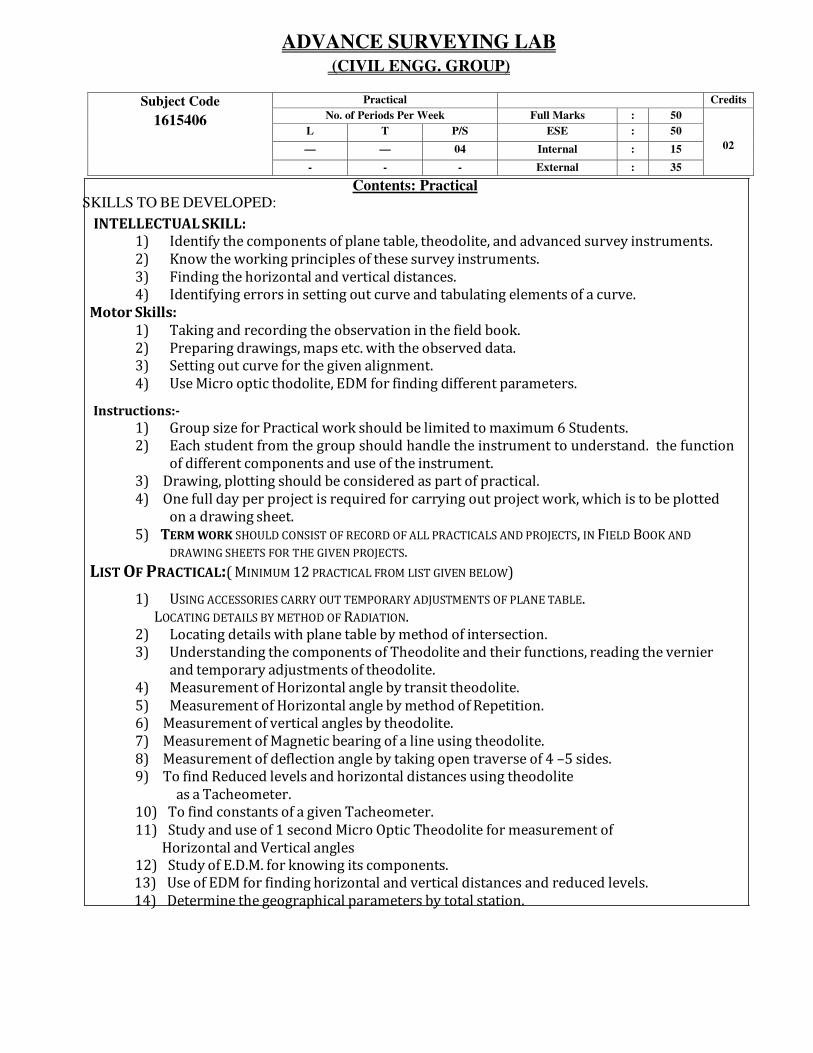
ADVANCE SURVEYING LAB
(CIVIL ENGG. GROUP)
Subject Code
1615406
Practical Credits
No. of Periods Per Week Full Marks : 50
02
L T P/S ESE : 50
— — 04 Internal : 15
- - - External : 35
Contents: Practical
SKILLS TO BE DEVELOPED:
INTELLECTUAL SKILL: 1) Identify the components of plane table, theodolite, and advanced survey instruments.
2) Know the working principles of these survey instruments.
3) Finding the horizontal and vertical distances.
4) Identifying errors in setting out curve and tabulating elements of a curve.
Motor Skills:
1) Taking and recording the observation in the field book.
2) Preparing drawings, maps etc. with the observed data.
3) Setting out curve for the given alignment.
4) Use Micro optic thodolite, EDM for finding different parameters.
Instructions:-
1) Group size for Practical work should be limited to maximum 6 Students.
2) Each student from the group should handle the instrument to understand. the function
of different components and use of the instrument.
3) Drawing, plotting should be considered as part of practical.
4) One full day per project is required for carrying out project work, which is to be plotted
on a drawing sheet.
5) TERM WORK SHOULD CONSIST OF RECORD OF ALL PRACTICALS AND PROJECTS, IN FIELD BOOK AND
DRAWING SHEETS FOR THE GIVEN PROJECTS.
LIST OF PRACTICAL:( MINIMUM 12 PRACTICAL FROM LIST GIVEN BELOW)
1) USING ACCESSORIES CARRY OUT TEMPORARY ADJUSTMENTS OF PLANE TABLE.
LOCATING DETAILS BY METHOD OF RADIATION.
2) Locating details with plane table by method of intersection.
3) Understanding the components of Theodolite and their functions, reading the vernier
and temporary adjustments of theodolite.
4) Measurement of Horizontal angle by transit theodolite.
5) Measurement of Horizontal angle by method of Repetition.
6) Measurement of vertical angles by theodolite.
7) Measurement of Magnetic bearing of a line using theodolite.
8) Measurement of deflection angle by taking open traverse of 4 –5 sides.
9) To find Reduced levels and horizontal distances using theodolite
as a Tacheometer.
10) To find constants of a given Tacheometer.
11) Study and use of 1 second Micro Optic Theodolite for measurement of
Horizontal and Vertical angles 12) Study of E.D.M. for knowing its components.
13) Use of EDM for finding horizontal and vertical distances and reduced levels.
14) Determine the geographical parameters by total station.

List Of Projects:
1) Plane table survey project for 5-6 sided traverse and locating details of buildings ,
Roads etc. by radiation and Intersection method , Sheet to be drawn by each
student separately on A-1 size imperial drawing sheet.
2) Theodolite traverse Survey for a closed traverse of 5-6 sides for a small
area. Computation by Gale’s traverse table. Plotting the traverse with
details on A1 size imperial drawing sheet.
3) Setting out simple circular curve by Rankine’s method of Deflection angles for a
given problem and plotting the details of curve on A-1 size imperial drawing
sheet

MECHANICS OF STRUCTURE LAB (CIVIL ENGG. GROUP)
Subject Code
1615407
Practical Credits
No. of Periods Per Week Full Marks : 50
01
L T P/S ESE : 50
— — 03 Internal : 15
- - - External : 35
Contents : Practical
Skill to be developed:
Intellectual Skills:
1. Interpret the results.
Calculate design parameters.
Motor Skills:
1. Observe the phenomenon during testing of specimen.
2. Draw the graphs and diagrams.
List of Practical:
Group – A (Any Six)
1. Identify the components of universal testing machine & tension test on mild steel.
2. Tension test on tor steel / deformed bars .
3. Izod Impact test on mild steel, brass, copper and cast iron.
4. Charpy impact test on mild steel, brass, copper and cast iron.
5. Flexural test on timber.
6. Flexure test on floor tiles or roofing tiles.
7. Shear Test on metal.
8. Water Absorption & Compression test (Dry & Wet) on bricks
9. Abrasion Test on flooring tiles.
Group - B
1. Drawing of Shear force and Bending Moment diagrams on
Graph Paper (6 Problems)
2. Graphical Solution of Two Problems on simple frames i) Cantilever
ii) Simply supported on A2 size sheet with their analytical solutions

GEO TECHNICAL ENGG. LAB (CIVIL ENGG. GROUP)
Subject Code
1615408
Practical Credits
No. of Periods Per Week Full Marks : 50
01 L T P/S ESE : 50
— — 02 Internal : 15
- - - External : 35
Contents: Practical
Skills to be developed:
Intellectual Skills:
a. Identify properties of soil.
b. Interpret test results.
c. Follow IS procedure of testing.
Motor Skills:
a. Measure the quantities accurately.
b. Handle the instruments carefully.
List of Practical (Any ten):-
1. Determination of water content of given soil sample by oven drying method
as per IS Code.
2. Determination of bulk unit weight dry unit weight of soil in field by core cutter
method as per IS Code.
3 Determination of bulk unit weight dry unit weight of soil in field by sand
replacement method as per IS Code.
5. Determination of Liquid limit & Plastic limit of given soil sample as per IS
Code.
6 Determination of grain size distribution of given soil sample by mechanical
sieve analysis as per IS Code.
7. Determination of coefficient of permeability by constant head test
8. Determination of coefficient of permeability by falling head test
Practical (Live demo or Prerecorded demo)
9. Determination of shear strength of soil using direct shear test.
10. Determination of shear strength of soil using Laboratory Vane shear test
11. Determination of MDD & OMC by standard proctor test on given soil sample
as per IS Code.
12. Determination of CBR value of given soil sample.
13. Determination of shear strength of soil using unconfined compressive
strength.
14. Determination of shear strength of soil using tri-axial shear test.

HYDAULICS LAB (CIVIL ENGG. GROUP)
Subject Code
1615409
Practical Credits
No. of Periods Per Week Full Marks : 50
02 L T P/S ESE : 50
— — 04 Internal : 15
- - - External : 35
Contents : Practical
Skills to be developed:
Intellectual Skills:
a. Interpret test results
b. Calculate quantities of parameters
c. Draw graphs
Motor Skills:
a. Measure different parameters accurately
b. Adjust levels by operating valves
List of Practical:
1. Measurements of pressure and pressure head by Piezometer, U-tube manometer
2. Measurement of pressure difference by U-tube differential manometer. Study of bourdon’s gauge
3. Verification of Bernoulli’s theorem
4. Reynolds experiment to study types of flow.
5. Determination of Darcy’s friction factor for a given pipe
6. Determination of Minor losses in pipes (any two)
7. Study and use of Moody’s diagram, Nomogram of Manning’s equation
8. Determination of Manning’s constant or Chezy’s constant for given rectangular channel section.
9. Demonstration of Hydraulic jump
10. Determination of coefficient of discharge for given rectangular or triangular notch.
11. Determination of coefficient of discharge for a given Venturimeter.
12. Demonstration and use of Pitot tube and current meter
13. Determination of hydraulic coefficients for sharp edge orifice.
14. Study & use of water meter.
15. Study of a model of centrifugal and reciprocating pump.
16. Use of characteristic curves/ nomograms /charts / catalogs from manufactures for selection of
pump for the designed discharge and head (Refer IS: 9694)
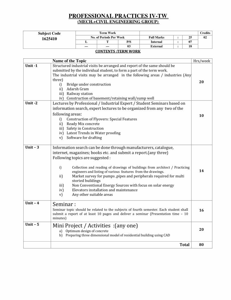
PROFESSIONAL PRACTICES IV-TW (MECH.+CIVIL ENGINEERING GROUP)
Subject Code
1625410
Term Work Credits
No. of Periods Per Week Full Marks : 25 02
L T P/S Internal : 07
— — 03 External : 18
CONTENTS :TERM WORK
Name of the Topic Hrs/week
Unit -1 Structured industrial visits be arranged and report of the same should be
submitted by the individual student, to form a part of the term work.
The industrial visits may be arranged in the following areas / industries (Any
three)
i) Bridge under construction
ii) Adarsh Gram
iii) Railway station
iv) Construction of basement/retaining wall/sump well
20
Unit -2 Lectures by Professional / Industrial Expert / Student Seminars based on
information search, expert lectures to be organized from any two of the
following areas: i) Construction of Flyovers: Special Features
ii) Ready Mix concrete
iii) Safety in Construction iv) Latest Trends in Water proofing
v) Software for drafting
10
Unit – 3 Information search can be done through manufacturers, catalogue,
internet, magazines; books etc. and submit a report.(any three)
Following topics are suggested :
i) Collection and reading of drawings of buildings from architect / Practicing
engineers and listing of various features from the drawings.
ii) Market survey for pumps ,pipes and peripherals required for multi
storied buildings
iii) Non Conventional Energy Sources with focus on solar energy
iv) Elevators installation and maintenance
v) Any other suitable areas
14
Unit – 4 Seminar : Seminar topic should be related to the subjects of fourth semester. Each student shall
submit a report of at least 10 pages and deliver a seminar (Presentation time – 10
minutes)
16
Unit – 5 Mini Project / Activities :(any one) a) Optimum design of concrete
b) Preparing three dimensional model of residential building using CAD
20
Total 80

COMPUTER AIDED DRAWING - TW (CIVIL ENGINEERING GROUP)
Subject Code
1615411
Term Work Credits
No. of Periods Per Week Full Marks : 25 02
L T P/S Internal : 07
— — 03 External : 18
CONTENTS: TERM WORK
Name of the Topic Hrs/week Unit -1 CAD Software
Meaning, various CAD software available in the market AutoCAD,
Felix Cad, Auto Civil, 3D Max ; etc.)Starting up of CAD, CAD
Window,
Tool bar, Drop down menu, Command window, Saving the
drawing. Introduction of Graphic screen.
Unit -2 CAD Commands
WCS icon, UCS icon, co-ordinates, drawing limits, grid, snap, ortho
features.
Drawing commands, line, circle, polyline, multiline, ellipse, polygon
etc.
Editing commands – Copy, move, offset, fillet, chamfer, trim,
lengthen, mirror, rotate, array etc.
Working with hatches, fills, dimensioning, text etc.
Unit – 3 Submission / Working Drawing
Generation of line plan, Detailed Plan, elevation, section, site plan,
Area statement
Generation of 3D view and print commands
Introduction to Auto Civil , 3D Max.
Note: Above theoretical aspects should be covered in the practical periods.
A) Building Drawing:
Following exercises shall be completed with CAD software and Print of all the drawings should be
prepared on A3 / A4 size paper
1) Preparation of line plan of a residential building.
2) Preparation of line plan of a Public building.
3) Preparation of detailed plan of a small residential building .
4) Preparation of submission drawing of residential building – showing Plan, Elevation,
Section, Schedule of openings, Site Plan and Area Statement
B) Civil Engineering Drawing.
Preparation of Drawings with CAD software for the following exercises (Any THREE) and Print of
all the drawings should be prepared on A3 /A4 size paper.
1) Plan, Cross Section and Longitudinal section of a Culvert (Pipe culvert/Box Culvert). 2) Section of an Earthen Dam.
3) Plan and Section of K. T. Weir.
4) Cross Section of Retaining wall.
5) Bonds in brickwork – Plan and Elevation for English bond and Flemish bond for one
brick thick wall.
6) Cross Section of ESR.
7) Cross Section of Clarri-flocculator.

Text Reference Books:-
Titles of the Book Name of Authors Name of the Publisher
Reference Manual of AutoCAD
AutoDesk
Reference Manual of Felix cad
Felix CAD
Reference Manual of Intel CAD
--
Reference Manual of Auto Civil
--
Reference Manual of 3D- Max
--
Computer Aided Drawing R.C. Tayal Foundation Publishng