IV Characteristics
22
IV Characteristics Electricity Lesson 4
-
Upload
geraldo-garcia -
Category
Documents
-
view
69 -
download
0
description
IV Characteristics. Electricity Lesson 4. Learning Objectives. To recall the symbols for different circuit components. To investigate the characteristics of different components. Draw and explain the characteristics for a wire, a filament bulb, thermistor and diode. - PowerPoint PPT Presentation
Transcript of IV Characteristics

IV Characteristics
Electricity Lesson 4

Learning Objectives
To recall the symbols for different circuit components.
To investigate the characteristics of different components.
Draw and explain the characteristics for a wire, a filament bulb, thermistor and diode.
Explain how and why resistance depends on temperature for metals and semiconductors.
Circuit Symbols?
Ammeter Voltmeter Cell Indicator or Light
Source Diode Light Emitting
Diode Resistor
Variable Resistor Thermistor Light Dependent
Resistor Heater Electric Motor

Complete the Table
V I R
(a) 0.30 A 18 Ω
(b) 12 V 88 Ω
(c) 14.4 V 0.52 A

Ammeter
An ammeter measures the current through part of the circuit. It is always connected in series.

Voltmeter
A voltmeter measures the potential difference between two points. It is always connected in parallel.

Cell
A cell provides voltage to a circuit. This pushes the charge around the circuit.

Lamp
The symbol for an indicator or any light source is the same (not including a light emitting diode).
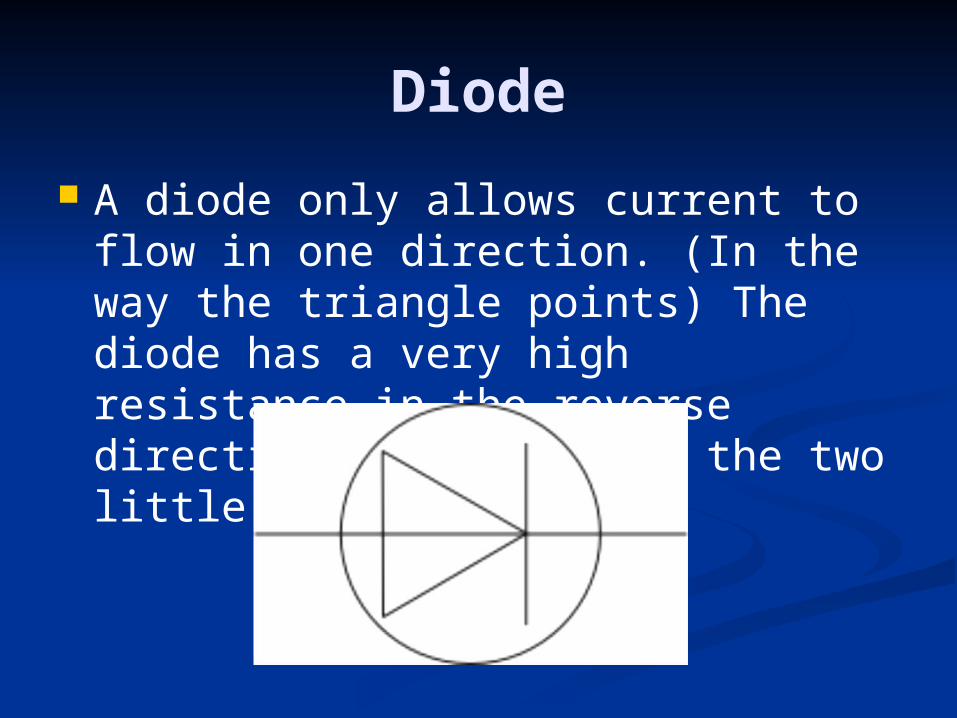
Diode
A diode only allows current to flow in one direction. (In the way the triangle points) The diode has a very high resistance in the reverse direction. (For LED add the two little arrows)
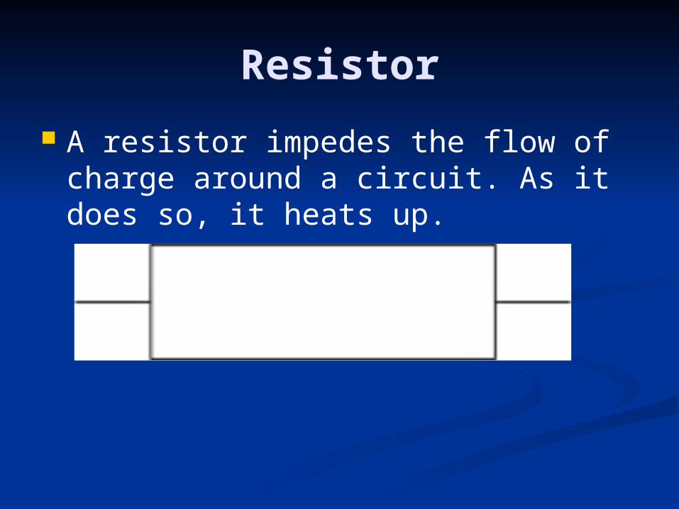
Resistor
A resistor impedes the flow of charge around a circuit. As it does so, it heats up.

Variable Resistor
A resistor that's value can easily be changed.

Thermistor
The resistance of a thermistor decreases as the temperature increases.

Light Dependent Resistor
An LDR is a light dependent resistor. Its resistance decreases as the amount of light falling on it increases.
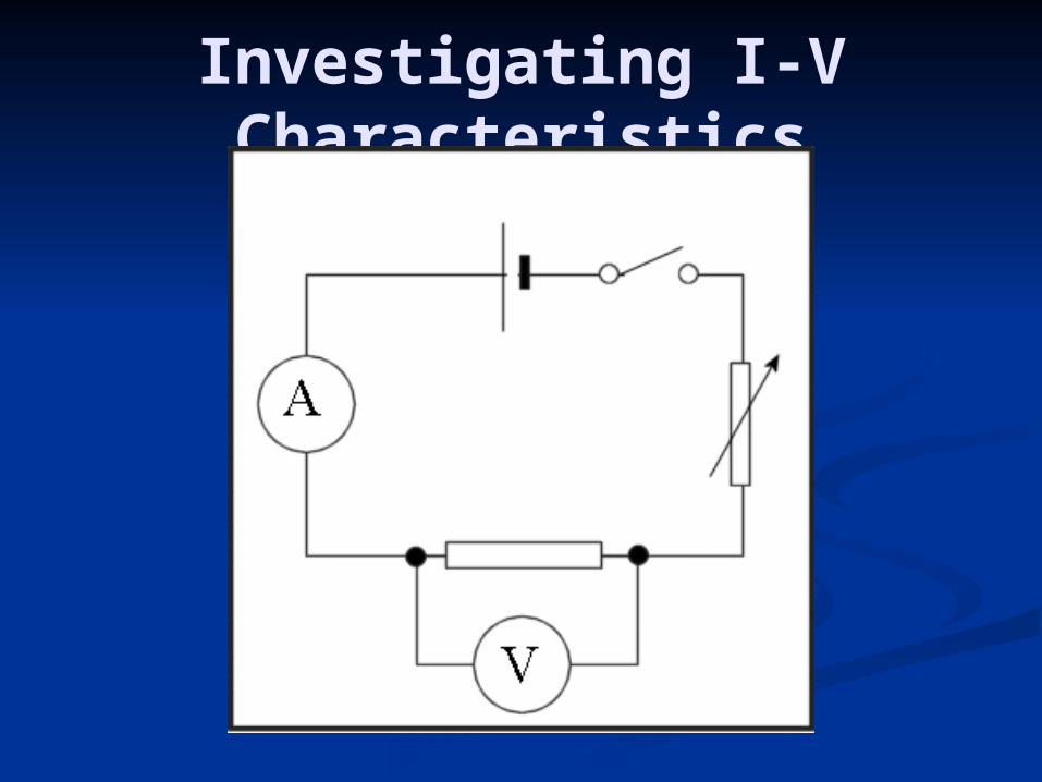
Investigating I-V Characteristics

Wire (Ohmic Conductor)
For a resistor, the current-voltage graph is a straight line through the origin.
The current through a resistor is directly proportional to the potential difference (voltage) across the resistor.
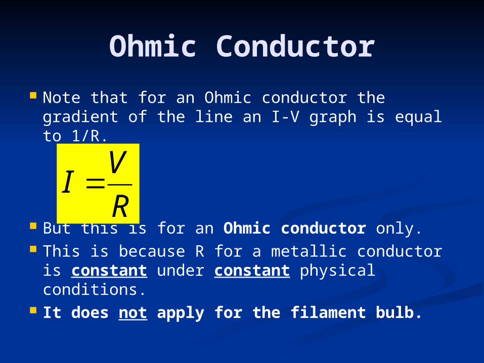
Ohmic Conductor
Note that for an Ohmic conductor the gradient of the line an I-V graph is equal to 1/R.
But this is for an Ohmic conductor only. This is because R for a metallic conductor is
constant under constant physical conditions. It does not apply for the filament bulb.
R
VI
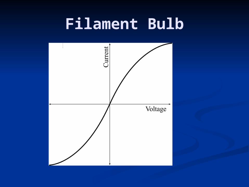
Filament Bulb

Filament Bulb
For a filament lamp, as the voltage increases, so does the current.
But the increased current raises the temperature of the filament bulb which also increases the resistance.
This is why the curve bends toward the end as it
is increasingly difficult for more current to flow.

Thermistor
At constant T, it gives a straight line.
The higher T is, the greater the gradient of the line as the resistance falls with increasing T.
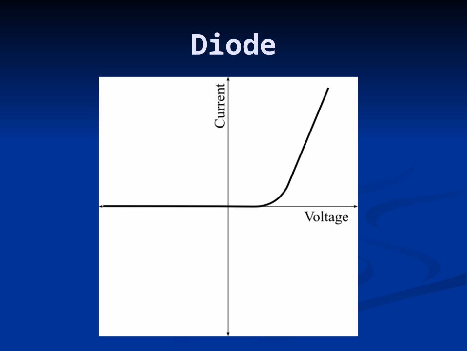
Diode
Diode Notes
The diode only allows current to flow in one direction (forward direction).
The diode has a high resistance in the opposite direction (reverse direction).
Needs a certain pd to conduct (typically about 0.6 V for silicon diode.)
Applications
Why does the resistance of metals increase with temperature?
Positive temperature coefficient.
Thermistor Temperature sensors Negative temperature coefficient. % change of resistance. Why? number of charge carriers.