
;IV - apps.dtic.mil · textiles,thus eliminating the need ýo test each textile by actual fragment...
33
;IV 5 -, Vl, . kCiNICAL RGPORT N-69.8 ARMY AIRCRAFT PROTECT1VE S1TRUCTURES :~. DESIGNS Repeft 3 RESPONSE OF SFLGCTED MATERIALS TO WIG14-SPEF-D FRAGMENT IMPACT J. W. Brownl, W. G. Dy~AM @siiubd bw U. S. Amiy fi~ pre "Vei Wvwww repolmmt StdkN,VkYb&sb, NAINLECHNICAL llo sfff ' I~ NK)RMATIU~N SERVICF-
Transcript of ;IV - apps.dtic.mil · textiles,thus eliminating the need ýo test each textile by actual fragment...
;IV 5-, Vl,
. kCiNICAL RGPORT N-69.8
ARMY AIRCRAFT PROTECT1VE S1TRUCTURES:~. DESIGNS
Repeft 3
RESPONSE OF SFLGCTED MATERIALS TO WIG14-SPEF-DFRAGMENT IMPACT
J. W. Brownl, W. G. Dy~AM
@siiubd bw U. S. Amiy fi~ pre "Vei Wvwww repolmmt StdkN,VkYb&sb,
NAINLECHNICAL llo sfff
' I~ NK)RMATIU~N SERVICF-

J75
> \
'\ ,' c.- '
D• 0 CUMEW T BES; T
QUALITY AVAILABLE. T" E OYITIP NTS.ED TO DTI CONTiNED
A SiGNIC.ANT NUMBER OF1-71B1 0 ýT 0OT
REPRODUCED FROMBEST AVAILABLE COPY

SYcUSIPv Classification
DOCUMENT CONTROL DATA. R & Dv.#* d.' .5! In'A en ri whef :htq~ -t .±i renotr1 r~il iltd
IOfttOlNATiNO ACTIVITY tCurie euhtor) na.RPOWy SECUMITY CLASSIPICA rnON
- - *,Job. GROUP
IREPORT TITLE
4 NCRIPTIVI NOTED (Irip* at report and lncimnv. doitnj
IATHOR(Sl) (PIjES) narn, miiddt. #rIllet, Tntnas.
REFIPORT DATE Too. TOTAL NO. OF PAGES9 h O.O RP
10. CONTRACT OR GRANT NO ES. ORIGINATOR'S REPORT NIWlIA'RISI
. R0.'EC No. AIA' c A j Tel 1, -f 1 1 ii- 1 ' I' k1;fcI.-
9. rtb. �OTHER REPORT NOISI (Any other numlbereo that may he Designed
10. DISTRIBUTION STATEMVENT
M UPPLEMENTARY NOTES1 I '.PONSORING MI LITARY ACTIVITY
11 ISITRACTn o'--'to -ie:oigti effec"tive I fcrtiLflt l'7'()t[2l-ti0L 0"Ili-tli-c; thaft will t I tO ,. icii- 0 f !A. , ii 'Ci-
rin lait eritl ti it jis Cnot ciBis ty to tin-i r. l:ttc iI the' he] VirL' Of' iarliQIiI:; Ctatitria k ill i-,,I i '..l'...t. i
TIllef~',a nisi-cly hlar b-etcl :onduil-te,-i urlr.1a1 ti-:ctili-c; wioodi, tit' i-alth,11 to tclti li tinn I Xi iI(of tilt' baste" j'icyc; i,. I. lawn cýovct'n ink ticilt' 'cc:lo; con- to, f.,,Ii- t cý-at -ai cc A'ian'i tfil'-- ic-a c'l_ t'i ta i tl 1,c o tile Viuaiio cli tn'mt,, - ftcR; W--ell :: c:''I ltn 1,c ' 1 1 7 '1ý - l0t - Mý i- tA till'
poje-.tilen aecr onc-i have yiz- icI-- itir i-,Ict into tte aicii :cc-hani'-cf:WIrjn nt~-i C ! "'n. , Mi-If-lti"ne I y ic .vltIplctll tiincc withi pi-oji-itilI :- wcli-i~ltng ic 7 t al-c ol I 0 I'mO 1- ill-' at vcl-
1 'Ic tin -tl't c:rIl
50 -ý 9-Ot ,000- it/cr. 4 frvcc tile--f teýt' tnle il-- ISti to Iiliii-ltcit tile Ii-IccioAnr -ý
vcoio-ity, an-I fienr'tt'i'ion -irptlic 0' tic' pctojnrXt I- ( tc i-cc icIf I ic'-i -. 11"' 1 Oil , ''i, T1' .......
'iiiccri-nt fciirc iOiithalt are- lic-f f' -Ilit on ti, ilcpftc' vI, i -,I& it"',cf, tl:t- -'v c -lU 1 J I '1, 1 i- 0!f
baiqlti-tie nylon, Ti-ct ri-oftc; how-cae-i tinat as tio farojec-tLI]'2 tcirip' t Xc i iil'lic I iiI cdl' c!n-ic-'tip wa: reac-ie'- at wi'ici--i tics rtaloci fcc Ic i Icic flatch;; upin ii: ' C -1 A-i I I ill-I ll 111 I - ..i--c.'
itation. * 'le t racouIti; aloe bit i-flt
, U1' tc ti, I L- tttl r'ctft-ll tiil li cc %u: (-1c 1. 1 ''1 w: rl l~'i (ll uIlnot liicear,1 i l oobliin,' tiis ti1 ic-b ; li'0 the 'lh idi not -oidot- A' I 'Ic-Ic i'X 'If
inflonaatioa VLineam- in the stfIi ly tni-ion wanl rXtrapfcPtc! to ifci i--t i t'-c-ci''c Icc Icr~icl 0f 1.),-
iciyai-aRl pcop-tic; o tice ten i i- , thicl I I icaifctctiflc tici: I,,c: c to tU-1t i-t . L'. i'c1 i ' i fcc - ,, .1
ni-f th to, I fc-tut ol t r I'tX lI ii,e mal w- 011 i it. cii1 i -1 'lý ti''j. ii
hve- to prceotrai-c . fl-f-tic:-o 1O n , f i-ccc-I'a n I "i 11' tiv- tc f-' ciki' c , !,''- '
cc -a -'tli'i iX i-fi c'-a'-,i Iivi - .c Icicii vc'- u: Cii c cIc- 'll I Fc -vc-i-aýr-cnc sd-Iic :-tltkifcc vv-if-'n~y to cc i,-"t'ic .iti' ylpo/,1.
cliiin ':eo'iti-, IcX~ ti-i ic- f''c'r tcrcc1.e
-l -cIO Irt-c-c ot hcg 'i- it.; !cI 's. ['"i-c-f I-at ica ,fpt!, in. c ! -;
- - al-c'citlonaliry 10--i vl -Acii Iiic iinci"c "Ph c ,:iq IW cc-,-' i'l
jw lc'q-Ii- l 'i ','li otlikilnj ye 'iccht,. in.!' c 1'. if c
<ts!t nn'-! -tic'locc i-t- '-ouit iccc I cac nIcew ilctellat -tncc Xio''- A'c, -I- I - I itiX,'' Z cc
DD -06M.47 SSLETE POrN AWAuY U0SE:i-; !i
rcuflty ClassIficaIon.
37

!1
|~O!O ih se~r~ hio ie-,t when no icnger nve,69. Do not raturr i
IIt~i iz the I
The findings in this reion are not to bo construed as an officialNpartment of the Army position unless so designmtnd
by other authoriaed ,.cumemo.

U~nclai3Izif i,:,
"Bwcurity C a ssliri cat ion - -______________________ L INK A - L,,lK 0 LINKm C
Aircraft T J r
AicatROLE
* ROLE -T MOL IE-V
A r m y a i r c r a f t "
Clays
Impact
Nylon
Plywoo IProjew:tiles
Protective lstruc ture:
Weapon fragmentation
Ikeewit1y Clssam~cation
'F8

TECHNICAL REPORT N-69-8
ARMY AIRCRAFT PROTECTIVE STRUCTURESDESIGNS
Report 3
RESPONSE OF SELECTED MATERIALS TO HIGH-SIPEEDFRAGMENT IMPACT
by 'I
J. W. Brown, W. G. Dykes
August 1971
Sponsored by Office, Chief of Engineers, U. S. Army
Project 4A662708A859
Conducted by U. S. Army Engineer Waterways Experiment Station, Vicksburg, Mississippi
ARMY.MRC VICKSKUNO. MISI S,•:
APPROVED FOR PUBLIC RELEASE; DISTRIBUTION UNLIMITED
*i~
%I
TEE CONTEWTS OF THIS REPORT ARE NOT TO
BE USED FOR ADVERTISING, PUBLICATION, OR
PROMOTIONAL PURPOSES. CITATION OF TRADE
NAMS DOES NOT CONSTITU'TE AN OFFICIAL EN-
DORSEMENT OR APPROVAL OF THE USE OF SUCII
COMMERCAL PRODUCTS.
;:?'
•i•3
ABSTRACT
rn order !.o design effective fragment protection schemes that will al-
low opt.;mum use of time, personnel, and materials, it is necessary to under-
stanu the belttvvoi- K f var!ou -m-ýAals under fragment impact. Therefore,
u study haLs been conducted using textiles, wood, and earth materials to
ga]in an understa•nding7 of the basic physical la•ws g-overning their response
Lo fraymen t impact.
•Mathematical analyses of the physical characteristics of the various
P materials as well as experiments in which fragment simulating projectiles
were used have yielded insight into the basic mechanics of fragment defeat.
Materials were tested by impacting them with projectiles weighing between
1.7 and 300 grains at velocities ranging from 500 to 5,000 ft/sec. Data
from these tests are presented to illustrate the relations between mass,
velocity, and penetration depths of the projectiles into ballistic nylon,
wood, sand, and clay. . .......TIhree different failure modes that are dependent on the impact veloc-
ity of' the projectile were identified for ballistic nylon. Test results
s;howed That as the projectile impact velocity increased, a critical veloc-
ity was reached at wbich the nylon sheared immediately upon impact, offer-
ing little resistance to penetration. Test results also indicated that the
relation between thickness and effectiveness of nylon was not linear, i.e.,
doubting the thickness of the nylon did not double its resistance to pene-
tration. The infoesation gtined in the study of nylon was extrapolated to
other textiles through consideration of the physical properties of the
textiles,thus eliminating the need ýo test each textile by actual fragment
impact.
'The effectiveness of plywood as a fragment defeating material is shown
in curves that describe depth of penetration or residual velocity for frag-
ments that penetrate. The wood was quite linear in its ability to defeat
fragments, as doubling its thickness doubled the impact velocity that a
fraeqent must have to penetrate.
Depths of penetration relative to striking velocity are presented for
sand and clay. The sand tests revealed some interesting results. For
•i•• i • •• i•'-• ''i =t~ • •i •i • ••-| '" i 4

example, in sand, the projectile penetration depth increased with striking
velocity only to a velocity of approximately 3,500 ft/sec. At this point,
increasing velocities resultcd in proportionately decreasing penelration
depths. The clay tests indicated that as fragment striking velocity in-creased, penetration depth increased In a decreasing. fashilon, with the ad-
ditional energy evidently being dissipated in the creation of a conical
cavity the volume of which increased with striking velocilty.
Based on the results ot ained In this study, it is recommended that
tests and studies be continied on new materials and on the interesting
characteristics of sand.
I,
if~ir
ii2
p t•
PRFl'ACE
The study reported herein was conducted by the Nuclear Weapons Effects
Divi.deon (NWI:D) of the U. S. Army Engineer Waterways Experiment Station
iWi) under the sponsorship of the Office, Chief of Engineers, as part of
the Army Aircraft 'rotective Structures Program, Project 4A662708A859, of
the Military Engineering Jesign and Expedient Construction Criteria Project.
The ,ýLudy was conducted during the period February through August 1969
under the general supervision of Mr. G. L. Arbuthnot, Jr., Chief of the
,IWIPýD, and Mr. W. J. ],lathau, Chief of the Protective Structures Branch, and
under the direct supervision of Mr.. J. T. Ballard, Chief of the Operations
Group. This report was prepared by Mr. J. W. Brown of the Analytical
Research Group, NWED, and Mr. W. G. Dykes of the Engineering Branch, Con-
structton Services Division, WES.
Directors of the WES during the conduct of this investigation and the
preparation and publication of this report were COL Levi A. Brown, CE, and
COL l.;rnest I). Ieixotto, C,. Technical Director was Mr. F. B. Brown.
6

CONTENTS
ABSTRACT ----------------------------------------------------- --- •-
PREFACE ....................... ACE.................... --------------- 6CONVERSION FACTORS, BRITISII TO M,-TRIC UNITS OF MN:A,,,TJPMNqT--------------8
INTRDCODUCTTION -------------------- ----------------------------- -9
Baekground --------------------------------------------------------- 9Ob Joe (-tires -----------------------------------------------------------
TESTS AND RESULTS ------------------------------------------------------- 10.
Description of Physical Facilities ------------------------------- .. 10Firing Devices and Pr'ojectiles -------------------------------------- 10Velocity Measurements ............................................ . 1.2Analysis of Material Response to Fragmpents -------------------------- 12
SUMMARY AND EECOE ,MILND.TIONS -------------------------------- ---------. 18
TABLE
1 Critical Velocity, Elongation, and Energy for VariousFrotective Materials ------------------------------------------- 19
FICUEES
L Fiýamncnt -imulation facility ----------------------------- 202 Velocity loss for 21-grain cube passing through 10 ft of air--- 213 Impacted filament prior to breaking ---------------------------- 214 Failure patterns for nylon filament ----------------------------- 225 Velocity loss for 21-grain cube in complete penetration of
nylon ---------------------------------------------------------- 226 Change in momentum for 21-grain cube penetrating ballistic
nylon ---------------------------------------------------------- 237 Energy loss for 21-grain cube in penetration of 8-, 12-, and
16-ply nylon blankets ------------------------------------------ 238 Velocity loss for 21-grain cube in 3/4-inch plywood.------------- 249 Velocity loss for 303-grain cylinder passIng througrh 2 and
3 thic]nosses of 3/4-inch fir plywood --------------------------- 21.0 Velocity loss for 21-grain cube passing tbrough combinations
of 8-ply nylon and 3/4-inch fir plywood ------------------------ 2511 Penetration in sand of 21-grain steel cube fra[,nent
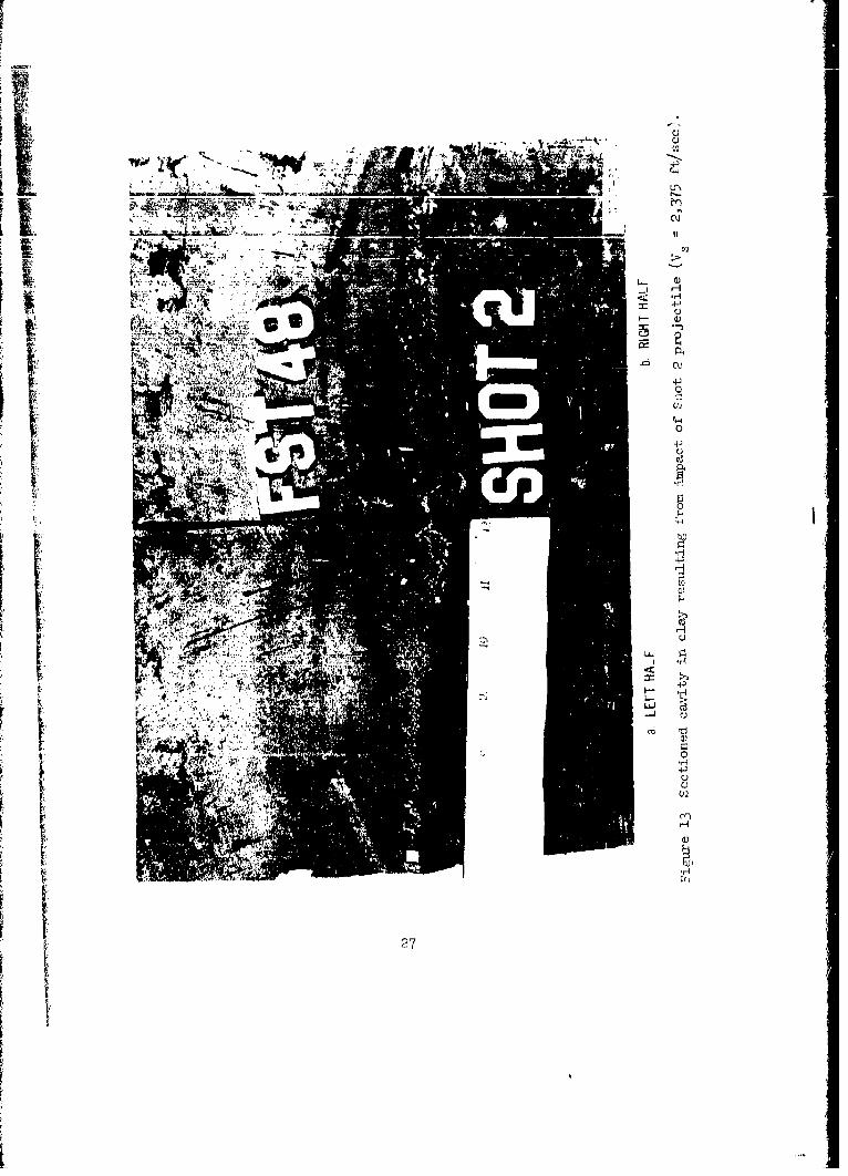
simulating projectile ------------------------------------------ 2512 Cavity in clay resulting from impact of Shot 1 projectile ------ 26113 Sectioned cavity in clay resulting from impact; of Shut 2
projectile ---------------------------------------------------- 271) 1 Cavity in clay resulting from impact of Shot 3 projcctile ------- .2815 Cavity in clay resulting from impact of Shot 5 projectile ------ -816 Cavity in clay resulting from impact of Shot 6 projec'tile ------ 29
'*1

Cn%,WEISTON FACTORS. BRITTSH TO METRTC UNITS OF MEASUREMENT
British units of measurement used in this report can be converted to metricunits as follows.
Multiply By To Obtain
inches 2.54 centi.meters
feet 0.3048 meters
square feet 0.092903 square meters
square yards 0.836127 square meters
ounces 28.3495 grams
grains 0.0o648 grams
pounds 0.45359237 kilograms
ounces per square foot 0.30515 kilograms per square meter
ounces per square yard 0.03391 kilograms per square meter
cubic feet 0.0283168 cubic meters
feet per second 0.3048 meters per second
i.
t 1IJ
INTRODUCTI ON
BACKGROUND
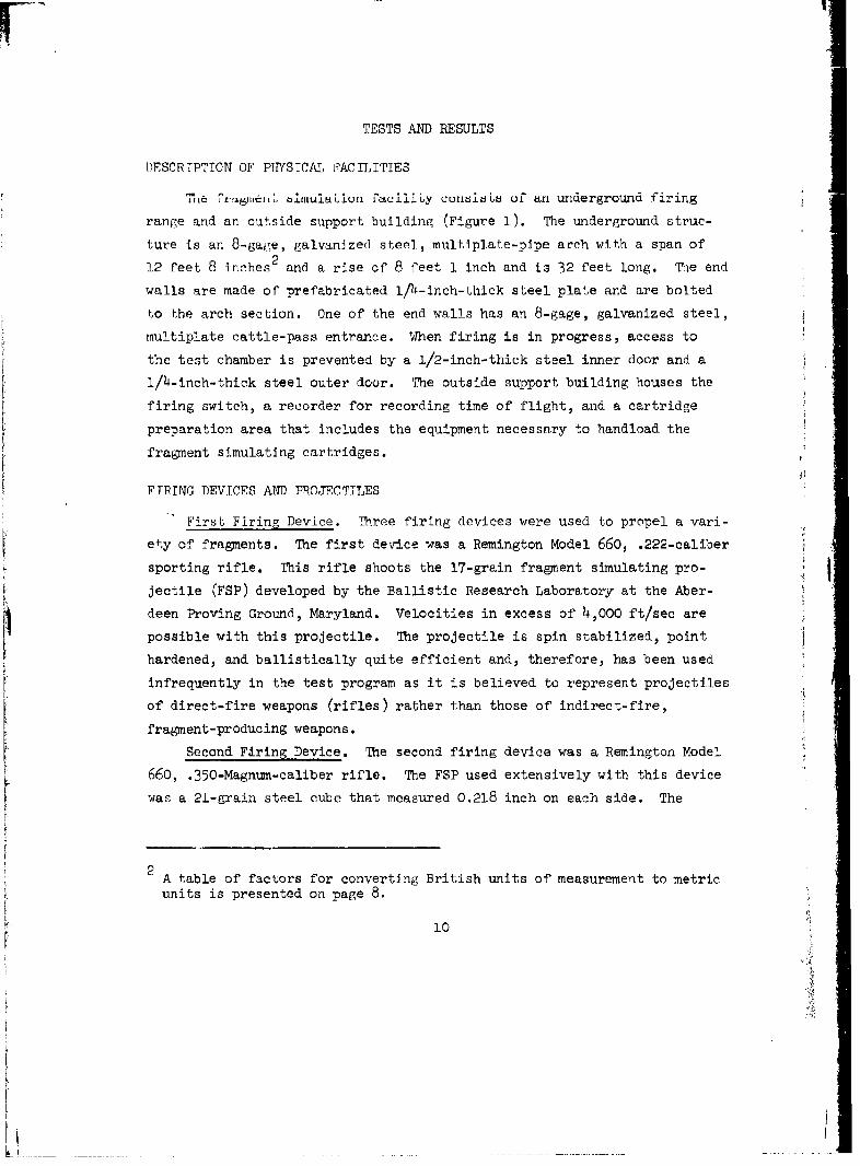
The work described herein was conducted as Part of the Army Aircraft
Protective Structures Program; this is one of a seri-s of reports dealing
with th!z subjcct. During the early phases of thei Aircraft SLtuctLure' PE'u-
gram work, it became evident to researchers that information dealing with
the mechanics of' fragments and the ability of various materials to defeat
fragments was not readily available. Thus, a stddy of fragment mechanicsand the effects of fragments on various materials was conducted to provide
designers with facts to be used in solving the protection problem.
OBJECTIVES
Ultimate objectives of the fragment mechanics study were to obtain in-formation on the ability of various materials to stop the penetration offragments from indirect-fire weapons and to define optimum orientation of
the materials whether used singularly or in combination with each other.
Before these objectives could be realized, several intermediate goals had
to be reached. A logical method of simulating a fragment by some standard
projectile had to be selected, and a facility for propelling the projectile
under closely controlled conditions had to be constructed. Researchers had
to choose from among many possible protective materials those few that best
met Army needs regarding availability, cost, weight, ease of construction,
and effectiveness. A test program had to be conducted, and the accumulated
data analyzed in order to categorize the best of the available data. Mate-
rials showing promise in the laboratory were selected for full-scale field
testing. Results of the field tests are included in Report 1 of this re-
port series. This report describes the handling of each of the intermedi-
ate goals described above and lists the conclusions drawn from each phase
of the work.
1 G. L. Carre and W. L. Huff; "Army Aircraft Protective Structures Designs;Helicopter Revetment Systems Using Field-Available Materials for Protec-tion Against Weapon Fragmentation"; Technical Report N-69-8, Report 1,November 1969; U. S. Army Engineer Waterways Experiment Station, CE,Vicksburg, Mississippi; Unclassified.
9
TESTS AND RESULTS
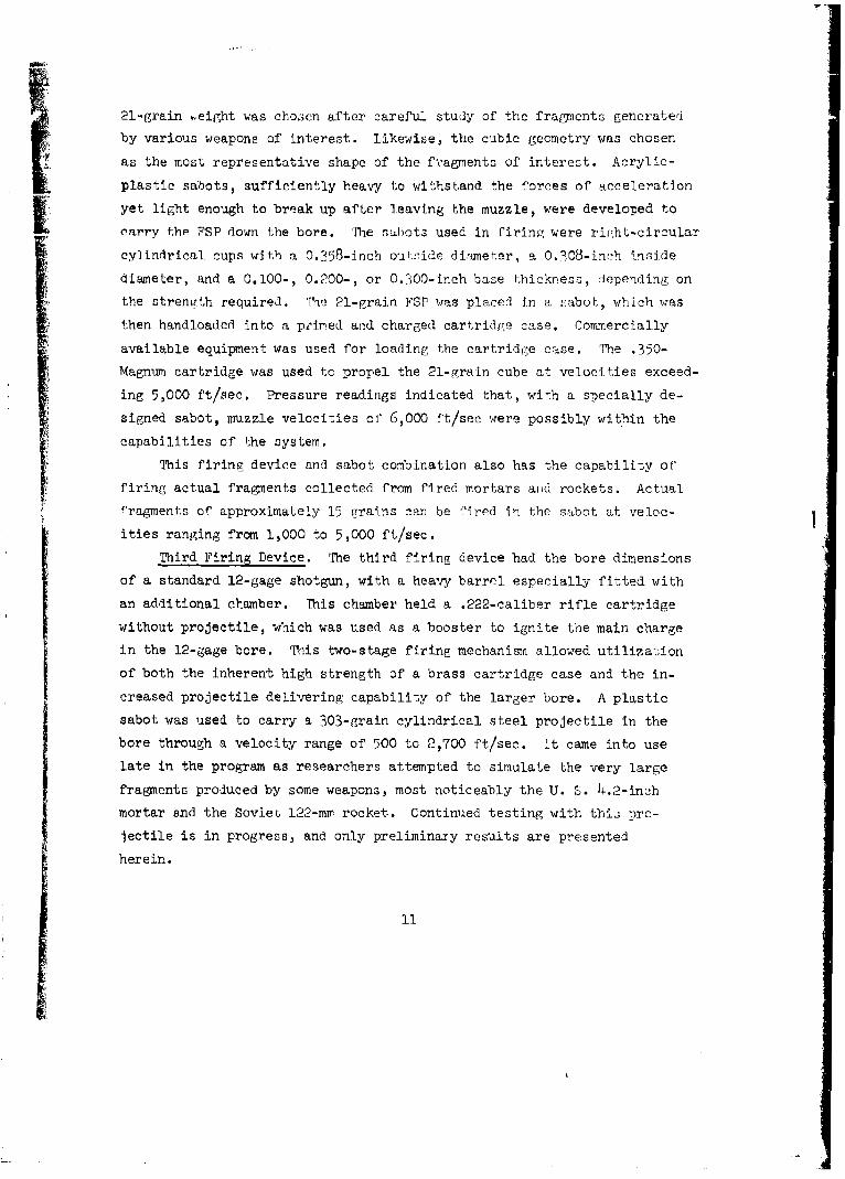
DESCRTPTION OF PHYSICAL FACILITIES
tue t eLtt~ u •itrLluiOLIU raclilLy coz±si!Ls of an underground firing
range and an outside support building (Figure i). The underground struc-
ture is an 8-gage, galvanized steel, multiplate-pipe arch with a span of
12 feet 8 inches 2 and a rise of 8 feet 1 inch and is 32 feet long. The end
walls are made of prefabricated 1/4-inch-thick steel plate and are bolted
to the arch section. One of the end walls has an 8-gage, galvanized steel,
multiplate cattle-pass entrance. When firing is in progress, access to
the test chamber is prevented by a 1/2-inch-thick steel inner door and a
1/h-inch-thick steel outer door. The outside support building houses the
firing switch, a recorder for recording time of flight, and a cartridge
preparation area that includes the equipment necessary to handload the
fragment simulating cartridges.
FTRTNG DEVICES AND PROJECTILES
First Firing Device. Three firing devices were used to propel a vari-
ety of fragments. The first device was a Remington Model 660, .222-caliber
sporting rifle. This rifle shoots the 17-grain fragment simulating pro-
jectile (FSP) developed by the Ballistic Research Laboratory at the Aber-
deen Proving Ground, Maryland. Velocities in excess of 4,000 ft/sec are
possible with this projectile. The projectile is spin stabilized, point
hardened, and ballistically quite efficient and, therefore, has been used
infrequently in the test program as it is believed to represent projectiles
of direct-fire weapons (rifles) rather than those of indirect-fire,
fragment-producing weapons.
Second Firing Device. The second firing device was a Remington Model
660, .350-Magnum-caliber rifle. The FSP used extensively with this device
was a 21-grain steel cube that measured 0.218 inch on each side. The
A table of factors for converting British units of measurement to metric
units is presented on page 8.
10
Li____
21-grain .eight was chosen after careful study of the fragments generated
by various weapons of interest. Likewise, the cubic geometry was chosen
as the most representative shape of the fragments of interest. Acrylic-
plastic sabots, sufficiently heavy to withstand the forces of acceleration
yet light enough to break up after leaving the muzzle, were developed to
carry thp FSP down the bore. The sulbots used in firing were right-circular
cylindrical cups with a 0.358-inch ouL:-ide dinmeter, a 0.308-inch inside
diameter, and a 0.100-, 0.200-, or 0.300-inch base thickness, d]epending on
the strength required. The 21-grain FSP was placed in a sabot, which was
then handloaded into a prired and charged cartridge case. Commercially
available equipment was used for loading the cartridge case. The .350-
Magnin cartridge was used to propel the 21-grain cube at velocities exceed-
ing 5,000 ft/sec. Pressure readings indicated that, with a specially de-
signed sabot, muzzle velocities of' 6,000 ft/sec were possibly within the
capabilities of the system.
This firing device and sabot combination also has the capability of'firing actual fragments collected from fired mortars and rockets. Actualfragments of approximately 15 grains can be fired in the sabot at veloc-
ities ranging from 1,000 to 5,000 ft/sec.
Third Firing Device. The third firing device had the bore dimensions
of a standard 12-gage shotgun, with a heavy barrel especially fitted with
an additional chamber. This chamber held a .222-caliber rifle cartridge
without projectile, which was used as a booster to ignite the main charge
in the 12-gage bore. This two-stage firing mechanism allowed utilization
of both the inherent high strength of a brass cartridge case and the in-
creased projectile delivering capability of the larger bore. A plastic
sabot was used to carry a 303-grain cylindrical steel projectile in the
bore through a velocity range of 500 to 2,700 ft/sec. It came into use
late in the program as researchers attempted to simulate the very large
fragments produced by some weapons, most noticeably the U. S. 4.2-inch
mortar and the Soviet 122-mm rocket. Continued testing with thi" pro-
jectile is in progress, and only preliminary results are presented
herein.
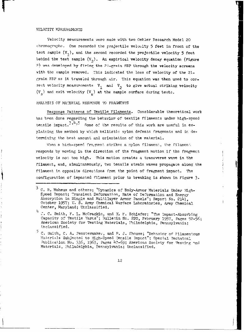
VELOCITY MEASUREMENTS
Velocity measurements were made with two Oehler Research Model 20
ehronographs. One recorded the projectile vel0,dity 5 feet in front of the
test sample (V,), and the second recorded the projectile velocity 5 feet
behind the test sample (V2 ). An empirical velocity decay equation (Figure
P) wn developed by firinor tbe I-grRin FSP through the velocity screens
with the sample removed. This indicated the loss of velocity of the 21-
g1rain FSP as it traveled through air. This equation was then used to cor-
rect velocity measurements V1 and V2 to give actual striking velocity
(V s) and exit velocity (Ve) at the sample surface during tests.
ANALYSTS OF MATERIAL RESPONSE TO FRAGMENTS
Response Patterns of Textile Filaments. Considerable theoretical work
has been done regarding the behavior of textile filaments under high-speed
tensile impact.3'4'5 Some of the results of this work are useful in ex-
plaining the method by which ballistic nylon defeats fragments and in de-
termining the best amount and orientation of the material.
When a hirh-speed fragment strikes a nylon filament, the filament
responds by moving in the direction of the fragment motion if the fragment
velocity is not too high. This motion creates a transverse wave in the
filament, and, simultaneously, two tensile strain waves propagate along the Ifilament in opposite directions from the point of fragment impact. The
configuration of impacted filament prior to breaking is shown in Figure 3.
C. B. Maheux and others; "Dynamics of Body-Armor Materials Under High-Speed Impact; Transient Deformation, Rate of Deformation and EnergyAbsorption in Single and Multilayer Armor Panels"; Report No. 2141,October 1957; U. S. Army Chemical Warfare Laboratories, Army ChemicalCenter, Maryland; Unclassified.J. C. Smith, F. L. McCrackin, and H. F. Schiefer; "The Impact-AbsorbingCapacity of Textile Yarns"; Bulletin No. 220, February 1957, Pages 52-56;American Society for Testing Materials, Philadelphia, Pennsylvania;Unclassified.
C. Smith, C. A. Fenstermakev, and P. J. Shouse; "Behavior of FilamentousMaterials Subjected to High-Speed Tensile Impact"; Special TechnicalPublication No. 336, 1.963, Pages 47-69; American Society for Testing .ndMaterials, Philadelphia, Pennsylvania; Unclassified.
12
___ ___ ___ ___ __ ___ __ ___ __ ___ ___ ___ ___ ___ ___ __ ___ ___ ___ ___ ___ ___ ___ ___ ___ ___ ___ ___ _-

In Figure 3, Point I is the impact point of the frarnent, and Point A
shows the position of the head of the transverse ý,ave. Point C indicates
the head of the tensile wave, and Point T3 shows the enl of' this wave.
Point D indicates material that is neither strained nor moving with theSt~~-r.-.C•v~i'-C "wav'c.
The velocity of the transverse wave front, U , at Point A is relatedto the tension, strain, and density of the filaxnent. by this eqluatinn:
U -)
Where: T'= tension in the filament
M = linear density of the unstrained filament
e = strain of the filament
Here U is expressed in Lagrangian rather than fixed coordinates. It isevident from the equation that whenever the local strain at the impact
point is great enough to produce rupture of the f'ilament, the tension drops
to zero, and the transverse wave no longer propagates. Thus, the amount offilament moving in the transverse wave and the unoiiil. of' enem absorbed] to
produce the transverse wave are hig}hly dropendenl, on t.,,e t.ime ai. w.li('h rup-.
ture strain is reached.
In addition to transferring energy to the filament to produce the
transverse wave, the fragment also transfers energy to produce the tensile
strain wave. Because of the interdependence of the transverse and tensilewaves, the rupture of the filament also causes an end to the propaigation
of the strain wave. 'Tus, the rate of strain is very important in detemnin-
Ing how much energy is transferred from the projectile to the filament be-
fore the filament breaks, andl this rate of strain Is directly proportional
to the velocity of the fragment.
One other important fact should be considered in describing the be-
havior of the filament during transverse impact.. There is a velocity limih
on the propagation of the transverse wave. 'Tis velocity limit has been
termed the critical velocity, and when a f'ilament is st.ruck by a projectile
at the critical velocity, the local strain becomes sufficient to producerupture before the transverse or tensile waves are formed. '[The projectile
'3
shears through the filament immediately upon impact, and the only energy
lost by the projectile is that required for shearing the filament.
These ideas allow the identificaticn of three distinct response pat-
terns of a textile ho a transverse impact. These response patterns are
desinated as tensile, transitional, and shear responses (Figure 4). The
ctiaracteristlcs oa" each response pattern are presented below.
1. Tensile response occurs at low impact velocities (!1,200 ft/sec).
The local strain around the projectile impact point does not reach the
level required for breaking the filament until a considerable amount of the
filament has responded in tension and transverse motion, resulting in a
maximun transfer of energy from fragment to filament. Some textiles, no-
tably nylon, can absorb relatively large amounts of energy at this low
strain rate. The total amount of energy absorbed prior to rupture of the
filament depends on the mass of the filament and its specific breaking en-
ergy. The specific breaking energy is proportional to the area under a
tension-strain curve from no strain to rupture strain for the material.
These are physical parameters that can be evaluated for various textiles
and used in comparing their relative energy absorption characteristics.
2. Transitional response occurs when a fragment strikes nylon at an
intermediate velocity level (1,200 to 2,200 ft/sec). At this level, the
transverse wave can form and begin to propagate, but only to a small extent.
Little material is put into tension, and an even smaller amount of the
filament is set into motion. The rate of strain is much higher than therate of propagation of the transverse wave, and breaking strain is reachedsooner:, resulting in a decrease in the energy transfer from fragment to
filament. However, the amount of energy transferred is still significant.
3. Shear response occurs when the impact velocity is so high (2,200
ft/sec) that the filament will not begin to transmit the transverse wave
before the local strain is sufficient to produce breaking. As stated ear-
lier, this velocity is called the critical velocity, and at or above the
critical velocity, the filament shears immediately upon impact. No trans-
verse or tensile waves are formed, and the energy transferred during this
type response is minimal. In fact, the energy transfer at this velocity is
so low tha!. a textile should not be considered for use as a fragment
14
LI
defeating material if fragment velocities higher than the critical velocity
are anticipated.
From the information presented above, It can be seen that for a tex-
tile material to be effective In defeating fragments it should possess the
following characteristics: (a) it -1 itýctcana h.•g•..• . tic.l veiuc-
ity; (b) it should stretch for a high percentafge of its length before
-heskinng; and (c) it sh1ouild ruquire a hifY Lewvl of ene.rgy to ;otretch the
Ifiber of which it is made. TabLe I (taken from .f-en,'vcnitoe1 in foot-
note ¾i on page 12) shows that nylon posiesse:s a bette:r -omhination of these
characteristics than do other synthetic fabric:.
Empirical Data on Response of Ballistic rNylon. Many tests were con-
ducted to evaluate the fragment defeating capability of ballistic nylon.
'Phis material is referred to in Akny supply channels as "Federal Stock
Number 8305-261-85 ib, cloth, ballistic, nylon, basket weave, 1.3.5 oz mini-
mum, 15 oz maximum wt/sq yd." A 12-ply blanket with grommets and exterior
weatherproof cover weighs approximately 21 oz/sq ft, and the procurement
cost is approximately $3.60 per sq rt.
Various sample thicknesses and orientations of ballistic nylon ...'ere
t.ested in the fragment simulation f'acil.l~y. Projee'iles w•ero f. ired 'Ll the
samples from a distance of ii feet, and velocities of the projectiles were
chronographed in front of and behind the samples. This arrangement allowed
a determination of both the velocity needed to penetrate the sample and the
velocity loss that the projectile sustained when the strikingi velocity was
high enough to cause penetration.
Results of some of the tests are presented in Figures 5 through 7.
The curves in the figures are based on the velocity change of a "1-grain
cube impacting loose-hanging nylon at right angeles. From Figures 5 ud 6,
it can be seen that for 8-, 12-, 1.6-, and 32-ply nylon blankets the loss in
projectile velocity (and hence loss of momentum) was essentially constant
regardless of the striking velocity, F'iLrure 7 shows an increase in energy
absorption by the nylon with an increase in strikingf velocity. Uowever,
when the striking velocity was high enough to keep the projectile moving
in the material at more than 2,200 Pt/sec, the effe,tiveness of the, nylon
declined sharply.
.15
Tn addition to the tests discussed above, tests were also conducted
with fragments striking the material at various impact angles, with the
material wet, with the material under slight tension, and with the plies of
the material separated to produce air gaps. No curves are given for theserj
Lei L6 as tlnay Z;10wld -d I - C h [L I tIlE ACaV.LU± UL bLAV LLYJAJLI.
The results are summarized as follows:
1. The loss in velocity that the projectile sustains when penetrating
a ballistic nylon blanket is minimumn if the projectile maintains a velocity
greater than 2,200 ft/sec while passing through the blanket.
2. Doubling the thickness of a nylon blanket will not double its ef-
fectiveness in stopping fragments.
3. There is no significant change in the effectiveness of the nylon
if it is angled up to 45 degrees relative to the path of the projectile.
4. There is no significant change in the effectiveness of the nylon
whether it is hanging loose or is under slight tension.
5. Wet nylon is as effective as dry nylon.
6. Air gaps between individual or groups of nylon layers do not in-
crease the effectiveness of the blanket.
7. At velocities greater than 2,000 ft/sec, a projectile will lose
as much velocity in passing through 10 feet of air as in passing through
four layers of standard nylon.
8. A projectile can be stopped by 32 plies of nylon if its striking
velocity is nearly critical. Adding layers beyond 32 plies yields diminish-
ing returns, as test results showed that the fragment that could penetrate
32 plies could generally penetrate 64 plies as well. This indicates that
the nylon blanket is more effective in the low-velouity regions (below
2,200 -ft/sec), and adding plies does not increase effectiveness enough to
justify the additional cost and weight.
Response of.Plywood. Both the 21-grain cube and the 303-grain cylin-
der were used iii studying the response of 3/4-inch fir plywood to fragment
impact. Results of the tests are plotted in Figures 8 and 9. Unlike bal-
listic nylon, the plywood seems to respond independently of the velocity
of the projectile. The velocity loss that the projectile sustains when
passing through the plywood is nearly the same over a very broad range
16
ýJ
of velocities. Also, the effectiveness of the plywood is nearly linear
with thickness.
Velocity loss is essentially constant in plywood regardless of impact
velocity, whereas ballistic nylon loses its effectiveness with increasing
limpueL velocity. Therefore, If plywood and nylon are used in combination,
the plywood should be placed in front of the nylon, which will enah1e t')
fragment velocity to be reduced by the wood prior to entering the nylon to
a velocity at which the nylon becomes more effective (see Figure 10).
Response of Sand and Clay. 2 sts were run on both dry anid saturated
sand in order to gain some idea of its effectiveness under general outdoor
conditions. These sand samples were containied in 1-cu-ft boxes made from
i/2-inch plywood. The sand, either we' ur dry, proved highly resistant to
penetration by the 21-grain cube. Trie curves in Figure 11 illustrate the
effectiveness of the sand in stopping fragments and also show the tendencyof the projectile to reach a maximum depth of penet~ration at velocities of
approximately 3,000 and 'j,500 ft/sec in dry and wet sand, respectively.
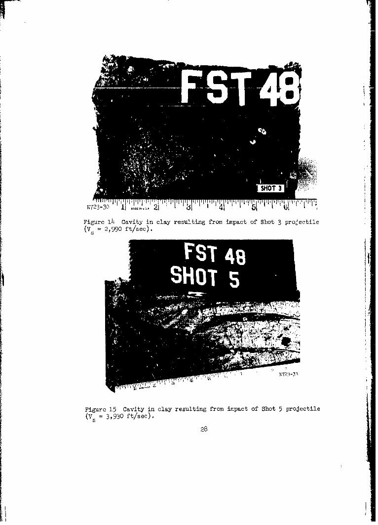
Velocities greater than 3,500 ft/sec do not yield increased penetration.The shots into moist clay (20 to 25 percent. molsture) shiowerl other- in-
teresting, tendencies. 'lhe impact of a projectile into a clay sample caused
a conical void in the clay with the projectile stopping in the vertex (see
Figures 12 through 16). Change in the depth of the cone was not linear
with a change in striking velocity. However, the volume of the cone in-
creased with increased striking velocity. Evidently, energy of a projec-
tile is expended both in penetration and creation of a cavity, and the lat-
ter becomes more important as velocity increases (see Figu2'es 12 through
16).Although the basic reasons for the interest~ing r'esponse of sell to
fragment impact are fit subjects for excellent theoretical analyses, the
practical fact learned from the tests conducted during this investigation
is that in all the shots conducted, none of the frnament ,i•!.utating projcc-
tiles completely penetrated I foot of earth maLerial. ýhen cost, erfective-
ness, and availability are considered, earth material remains an excellent;
choice for protective structure construction.
17

SLItM4RY AND REcOM1ENDATrONS
The fragment threat from a wide variety of indirect-fire weapons has
been modeled under laboratory conditions by using 'ragment simuja.iig pr,-
jt, r~les. The study was conducted in order to gain information on the rela-
tive effectiveness of various field-available materials for use as protee-
tion from frq-rrments. In addition to establishing the relative effective-
ness of various textiles, wood, sand, and clay, an insight into the mechan-
ics of fragment penetration in these materials was also gained. This ad-
ditional information was useful in material selection, location, orienta-
tion, etc., for maximum effectiveness as fragment protection. Other basic
engineering details such as the effects of moisture, air gaps, obliquity,
etc., which could alter the effectiveness of a protection scheme were also
researched and discussed.
Research should be continued on items of military interest, and any
new material that is developed can be immediately evaluated for posisible
military appli'ation. rn the future, some attention should be given to the
problem of constructing a table or other set of data that will give com-
parative effectiveness of a wide range of materials. Such a collection
should include data on ballistic nylon, plywood, various landing mats,
earth materials, etc.
18
TABLE 1 CRITICAL VELOCITY, ELONGATION, A.ND ENERGY FOR VARIOUS PROTECTIVEMATERIALS
Material Transverse Critical Breakini, Sppiific Breaking
Acetate 30.7 34-9
Glass fi'be-r i,420.
Nylon 2,2)10 1.1. T 3,. 5
Polyester i,830 8. 0 2) 1. 3Rayon 325.8
19
If'

.4k
ged
202
400
L.L(-3
->- - . -
z ,v 0.0722 V1 5.81SI ______._
LU
wL. 200 .. -00
> N
01. 0
>* SY METHOD OF
LEAST SQUARES
0 1,000 2.000 3,000 4,000 5,000
V 1, FT/SEC
Figure 2 Velocity loss for 21-grain cubepassing through 10 ft of air.
0
C
A
LEGEND
I FRAGMENT IMPACT POINTA HEAD OF TRANSVERSE WAVEB END OF TENSILE WAVEH HEAD OF TENSILE WAVED UNAFFECTED MATERIAL
Figure 3 Impacted filamentprior to breaking.
21
I•

-4-- V, 0 TO 1,200 FT/SEC
TENSILE RESPONSE
/ v. 1,200 TO 2,200 FT/SEC Figure 4 Failure patterns for nylonfilament (V8 is striking velocity).
TRANSITIONAL RESPONSE
V. 2,200 1 FT/SEC(CRITICAL VELOCITY)
SHEAR RESPONSE
2.0° 0
I, ,o.........- -- - -.. . ... - ~I----- -- ,
32 PLY
Idoo
1,00 - -___ -
S6 PL L
400 - "'- .... - "- •-":
0 M00 400 600 800 1.000 1.200 1,400 1,600 11800 2.000 2.200 2.400 2.600 2,800 3,000
STRIKING VELOCITY. FT 'SEC
Figure 5 Velocity loss for 21-grain cube in complete penetration of nylon.
22

0.301
0.2
I O2( _ .-...----.---.t.O
Cz
C
50i5t.0 20 50 1'0 030 020 .0 .5 .0
Fiae6Ch.ei mmnu fr2-rancb
I IP
So 2 50 I..00 -. 2- 1,0 .00 22 2.0 .5
E 20
IF
Figure 7 Energy T.oss for 21-grain cube in penetrationof 8-, 12-, and 16-piy nylon blaxiknts.
23

S~~THICKNESSES _
1.400 -° ,°, .I 1 .. ...------ 4 4 4 i II 1 1 1
w): -- 2 THICKNESSS
400 ROD
U 600
ITHICKNESS
400
200B00 750 1.000 1,250 1,500 1,750 2.000 2.250 2,500 2.750 3.000
STRIKING VELOCITY, FT "SEC
Figure 8 Velocity loss for 21-grain cube in 3/4-inch plywood.
3 THIC KNESSES
U 600
I,-
U.1
t- 2 THICKNESSES
400 "_
U 200!
0 ,,, _
500 750 1,000 1,250 1,500 1,750 2,000 2.250 2,500
STRIKINIG VELOCITY, FT.'SEC
Figure 9 Velocity loss for 303-grain cylinder passing through 2 and 3thicknesses of 3/4--inch fir plywood.
24
LAi
1,401.-. U Q I N FRONT '--LILL
UL~'WO IN FRON
U I I 1
601.000 1.2!,0 1,500 1.750 2.000 2.50 2.5W0 750 ,cx)
5 TRIK ING VELOCI17Y. F T •,J-C
Figure 10 Velocity loss for 21-graLin cube passing through combinations of8-ply nylon and 3/4-inch fir ply-wood.- ------- • ----V)
00 00
I',
z-3
z2 00
rlZW1 LEGEND
a. - WETSAND{ DRY SAND
1,000 1,500 2,000 2,500 3,000 3.500 4,000 4.500 5,000
VELOCITY V . FT SEC
Figure 11 Penetration in sand of 21-grain steel cube r'raLnent simulatingprojectile.
1..
FSIT
II
N723-27 11 21 01 U i
Figure 12 Cavity in clay resulting from impact of Shot 1 projectile(VS 1,8W1 ft/sec).
26
IT'
W C\j
ýMc-
"4'4-
,4J
HL
27U
'723-30 IjWAIA2 4
Figure 1~4 Cavity in clay resulting from impact of' Shot 3 projectile(V 2,990 ft/see).
Pot'
Figure 1.5 Cavity in clay resulting from impact of Shot 5 projectile(Vs 3,930 ft/sec).
28

r2
IA
Itig fom mpat o Sbt 6projectile
FI~ure 16 Cavity in, l2ay resi3t-L foimctO b (
29