Rec. ITU-T G.977.1 (10/2020) Transverse compatible dense ...

I n t e r n a t i o n a l T e l e c o m m u n i c a t i o n U n i o n
ITU-T G.808.1 TELECOMMUNICATION STANDARDIZATION SECTOR OF ITU
(05/2014)
SERIES G: TRANSMISSION SYSTEMS AND MEDIA, DIGITAL SYSTEMS AND NETWORKS
Digital networks – General aspects
Generic protection switching – Linear trail and subnetwork protection
Recommendation ITU-T G.808.1
ITU-T G-SERIES RECOMMENDATIONS
TRANSMISSION SYSTEMS AND MEDIA, DIGITAL SYSTEMS AND NETWORKS
INTERNATIONAL TELEPHONE CONNECTIONS AND CIRCUITS G.100–G.199
GENERAL CHARACTERISTICS COMMON TO ALL ANALOGUE CARRIER-TRANSMISSION SYSTEMS
G.200–G.299
INDIVIDUAL CHARACTERISTICS OF INTERNATIONAL CARRIER TELEPHONE SYSTEMS ON METALLIC LINES
G.300–G.399
GENERAL CHARACTERISTICS OF INTERNATIONAL CARRIER TELEPHONE SYSTEMS ON RADIO-RELAY OR SATELLITE LINKS AND INTERCONNECTION WITH METALLIC LINES
G.400–G.449
COORDINATION OF RADIOTELEPHONY AND LINE TELEPHONY G.450–G.499
TRANSMISSION MEDIA AND OPTICAL SYSTEMS CHARACTERISTICS G.600–G.699
DIGITAL TERMINAL EQUIPMENTS G.700–G.799
DIGITAL NETWORKS G.800–G.899
General aspects G.800–G.809
Design objectives for digital networks G.810–G.819
Synchronization, quality and availability targets G.820–G.829
Network capabilities and functions G.830–G.839
SDH network characteristics G.840–G.849
Management of transport network G.850–G.859
SDH radio and satellite systems integration G.860–G.869
Optical transport networks G.870–G.879
DIGITAL SECTIONS AND DIGITAL LINE SYSTEM G.900–G.999
MULTIMEDIA QUALITY OF SERVICE AND PERFORMANCE – GENERIC AND USER-RELATED ASPECTS
G.1000–G.1999
TRANSMISSION MEDIA CHARACTERISTICS G.6000–G.6999
DATA OVER TRANSPORT – GENERIC ASPECTS G.7000–G.7999
PACKET OVER TRANSPORT ASPECTS G.8000–G.8999
ACCESS NETWORKS G.9000–G.9999
For further details, please refer to the list of ITU-T Recommendations.

Rec. ITU-T G.808.1 (05/2014) i
Recommendation ITU-T G.808.1
Generic protection switching – Linear trail and subnetwork protection
Summary
Recommendation ITU-T G.808.1 defines the generic functional models, characteristics and
processes associated with various linear protection schemes for circuit-switched connection-oriented
layer networks; e.g., optical transport networks (OTN), synchronous digital hierarchy (SDH)
networks and packet-switched layer networks, e.g., asynchronous transfer mode (ATM) networks
and Ethernet transport networks.
It also defines the objectives and applications for these schemes. Protection schemes described in
this Recommendation are trail protection and subnetwork connection protection with various
monitoring alternatives for individual signals or groups of signals. Furthermore, survivability offered
by the link capacity adjustment scheme (LCAS) is described.
Generic functional models, characteristics and processes for ring protection and interconnected
subnetwork (e.g., ring) protection schemes are defined in other Recommendations.
History
Edition Recommendation Approval Study Group Unique ID*
1.0 ITU-T G.808.1 2003-12-14 15 11.1002/1000/7063
1.1 ITU-T G.808.1 (2003) Amd. 1 2005-07-14 15 11.1002/1000/8541
2.0 ITU-T G.808.1 2006-03-29 15 11.1002/1000/8761
2.1 ITU-T G.808.1 (2006) Amd. 1 2009-01-13 15 11.1002/1000/9650
3.0 ITU-T G.808.1 2010-02-22 15 11.1002/1000/10401
3.1 ITU-T G.808.1 (2010) Amd. 1 2012-08-06 15 11.1002/1000/11491
3.2 ITU-T G.808.1 (2010) Amd. 2 2012-09-21 15 11.1002/1000/11781
4.0 ITU-T G.808.1 2014-05-14 15 11.1002/1000/12180
____________________
* To access the Recommendation, type the URL http://handle.itu.int/ in the address field of your web
browser, followed by the Recommendation's unique ID. For example, http://handle.itu.int/11.1002/1000/11
830-en.
ii Rec. ITU-T G.808.1 (05/2014)
FOREWORD
The International Telecommunication Union (ITU) is the United Nations specialized agency in the field of
telecommunications, information and communication technologies (ICTs). The ITU Telecommunication
Standardization Sector (ITU-T) is a permanent organ of ITU. ITU-T is responsible for studying technical,
operating and tariff questions and issuing Recommendations on them with a view to standardizing
telecommunications on a worldwide basis.
The World Telecommunication Standardization Assembly (WTSA), which meets every four years,
establishes the topics for study by the ITU-T study groups which, in turn, produce Recommendations on
these topics.
The approval of ITU-T Recommendations is covered by the procedure laid down in WTSA Resolution 1.
In some areas of information technology which fall within ITU-T's purview, the necessary standards are
prepared on a collaborative basis with ISO and IEC.
NOTE
In this Recommendation, the expression "Administration" is used for conciseness to indicate both a
telecommunication administration and a recognized operating agency.
Compliance with this Recommendation is voluntary. However, the Recommendation may contain certain
mandatory provisions (to ensure, e.g., interoperability or applicability) and compliance with the
Recommendation is achieved when all of these mandatory provisions are met. The words "shall" or some
other obligatory language such as "must" and the negative equivalents are used to express requirements. The
use of such words does not suggest that compliance with the Recommendation is required of any party.
INTELLECTUAL PROPERTY RIGHTS
ITU draws attention to the possibility that the practice or implementation of this Recommendation may
involve the use of a claimed Intellectual Property Right. ITU takes no position concerning the evidence,
validity or applicability of claimed Intellectual Property Rights, whether asserted by ITU members or others
outside of the Recommendation development process.
As of the date of approval of this Recommendation, ITU had received notice of intellectual property,
protected by patents, which may be required to implement this Recommendation. However, implementers
are cautioned that this may not represent the latest information and are therefore strongly urged to consult the
TSB patent database at http://www.itu.int/ITU-T/ipr/.
ITU 2014
All rights reserved. No part of this publication may be reproduced, by any means whatsoever, without the
prior written permission of ITU.

Rec. ITU-T G.808.1 (05/2014) iii
Table of Contents
Page
1 Scope ............................................................................................................................. 1
2 References ..................................................................................................................... 1
3 Definitions .................................................................................................................... 2
3.1 Terms defined elsewhere ................................................................................ 2
4 Abbreviations ................................................................................................................ 6
5 Conventions .................................................................................................................. 8
6 Individual and group protection concept ...................................................................... 8
7 Architecture types ......................................................................................................... 9
7.1 1+1 protection architecture ............................................................................. 10
7.2 1:n protection architecture .............................................................................. 10
7.3 m:n protection architecture ............................................................................. 12
7.4 (1:1)n protection architecture .......................................................................... 13
8 Switching types ............................................................................................................. 15
9 Operation types ............................................................................................................. 16
10 Protocol types ............................................................................................................... 16
11 Protection classes and subclasses ................................................................................. 18
11.1 Trail protection ............................................................................................... 18
11.2 SNC protection ............................................................................................... 22
11.3 Subnetwork connection group protection ....................................................... 29
12 Survivability of inverse multiplexed link connections ................................................. 39
12.1 SIM functional model ..................................................................................... 40
13 Protection switching performance ................................................................................ 41
14 Hold-off timer ............................................................................................................... 42
15 Wait-to-restore timer .................................................................................................... 43
16 Automatic protection switching signal ......................................................................... 44
17 Non-pre-emptible unprotected traffic ........................................................................... 44
18 Extra traffic (protection) transport entity overhead/OAM ............................................ 44
19 External commands ...................................................................................................... 45
19.1 External commands for CL-SNC ................................................................... 45
19.2 External commands for ACL-SNC ................................................................ 46
20 Protection switching process states .............................................................................. 46
21 Priority .......................................................................................................................... 47
22 SF and SD trigger conditions ........................................................................................ 47
22.1 Overview of SF conditions ............................................................................. 48
22.2 Overview of SD conditions ............................................................................ 49
23 Working and protection allocation ............................................................................... 49

iv Rec. ITU-T G.808.1 (05/2014)
Page
24 APS protocol ................................................................................................................. 50
24.1 1-phase ............................................................................................................ 51
24.2 2-phase ............................................................................................................ 51
24.3 3-phase ............................................................................................................ 53
Appendix I – Implementation of hold-off timer ...................................................................... 55
Appendix II – Automatic conditions (SF, SD) in group SNC protection ................................ 56
Appendix III – Implementation observations .......................................................................... 58
III.1 Analysis .......................................................................................................... 58
Appendix IV – An example of (1:1)n protection...................................................................... 62
Appendix V – Examples of survivability of inverse multiplexed trails ................................... 63
V.1 Survivability offered by LCAS ...................................................................... 63
Appendix VI – Solution for SD triggered protection in PTN .................................................. 64
Appendix VII – Solution for service protection in DBN ......................................................... 65

Rec. ITU-T G.808.1 (05/2014) 1
Recommendation ITU-T G.808.1
Generic protection switching – Linear trail and subnetwork protection
1 Scope
This Recommendation provides an overview of generic aspects of linear protection switching. It
covers protection schemes applicable to circuit-switched and packet-switched layer networks; e.g.,
optical transport networks (OTNs), synchronous digital hierarchy (SDH), asynchronous transfer
mode (ATM) and Ethernet transport based protection schemes. Overviews of ring protection and
dual node subnetwork (e.g., ring) interconnection schemes will be provided in other
Recommendations.
2 References
The following ITU-T Recommendations and other references contain provisions which, through
reference in this text, constitute provisions of this Recommendation. At the time of publication, the
editions indicated were valid. All Recommendations and other references are subject to revision;
users of this Recommendation are therefore encouraged to investigate the possibility of applying the
most recent edition of the Recommendations and other references listed below. A list of the
currently valid ITU-T Recommendations is regularly published. The reference to a document within
this Recommendation does not give it, as a stand-alone document, the status of a Recommendation.
[ITU-T G.780] Recommendation ITU-T G.780/Y.1351 (2010), Terms and definitions for
synchronous digital hierarchy (SDH) networks.
[ITU-T G.783] Recommendation ITU-T G.783 (2006), Characteristics of synchronous digital
hierarchy (SDH) equipment functional blocks.
[ITU-T G.798] Recommendation ITU-T G.798 (2004), Characteristics of optical transport
network hierarchy equipment functional blocks.
[ITU-T G.805] Recommendation ITU-T G.805 (2000), Generic functional architecture of
transport networks.
[ITU-T G.806] Recommendation ITU-T G.806 (2009), Characteristics of transport equipment –
Description methodology and generic functionality.
[ITU-T G.826] Recommendation ITU-T G.826 (2002), End-to-end error performance
parameters and objectives for international, constant bit-rate digital paths and
connections.
[ITU-T G.841] Recommendation ITU-T G.841 (1998), Types and characteristics of SDH
network protection architectures.
[ITU-T G.842] Recommendation ITU-T G.842 (1997), Interworking of SDH network protection
architectures.
[ITU-T G.870] Recommendation ITU-T G.870/Y.1352 (2008), Terms and definitions for optical
transport network (OTN).
[ITU-T G.873.1] Recommendation ITU-T G.873.1 (2006), Optical Transport Network (OTN):
Linear protection.
[ITU-T I.610] Recommendation ITU-T I.610 (1999), B-ISDN operation and maintenance
principles and functions.
[ITU-T I.630] Recommendation ITU-T I.630 (1999), ATM protection switching.

2 Rec. ITU-T G.808.1 (05/2014)
[ITU-T I.732] Recommendation ITU-T I.732 (2000), Functional characteristics of ATM
equipment.
[ITU-T M.495] Recommendation ITU-T M.495 (1988), Transmission restoration and
transmission route diversity: Terminology and general principles.
3 Definitions
3.1 Terms defined elsewhere
This Recommendation uses the following terms defined elsewhere:
3.1.1 General terms defined in [ITU-T G.805]:
a) adapted information (AI).
b) characteristic information (CI).
c) link connection.
d) network.
e) serial compound link connection.
f) subnetwork.
g) trail.
3.1.2 Action-related terms:
3.1.2.1 switch: [ITU-T G.870].
3.1.3 APS protocol-related terms:
3.1.3.1 1-phase: [ITU-T G.870].
3.1.3.2 2-phase: [ITU-T G.870].
3.1.3.3 3-phase: [ITU-T G.870].
3.1.4 Protection class-related terms:
3.1.4.1 trail protection: [ITU-T G.870].
3.1.4.2 subnetwork connection protection: [ITU-T G.870].
The determination of a fault condition on a serial compound link connection within the protected
domain can be performed as follows:
3.1.4.2.1 sublayer monitored (/S): [ITU-T G.870].
3.1.4.2.2 non-intrusive monitored (/N): [ITU-T G.870].
3.1.4.2.3 inherent monitored (/I): [ITU-T G.870].
3.1.4.2.4 test monitored (/T): [ITU-T G.870].
3.1.4.3 network connection protection: [ITU-T G.870].
3.1.4.4 individual: [ITU-T G.870].
3.1.4.5 group: [ITU-T G.870].
3.1.5 Protection subclass-related terms:
3.1.5.1 end-to-end overhead/OAM (e): [ITU-T G.870].
3.1.5.2 sublayer overhead/OAM (s): [ITU-T G.870].
3.1.6 Component-related terms:
Rec. ITU-T G.808.1 (05/2014) 3
3.1.6.1 protected domain: [ITU-T G.870].
3.1.6.2 bridge: [ITU-T G.870].
3.1.6.3 permanent bridge: [ITU-T G.870].
3.1.6.4 broadcast bridge: [ITU-T G.870].
3.1.6.5 selector bridge: [ITU-T G.870].
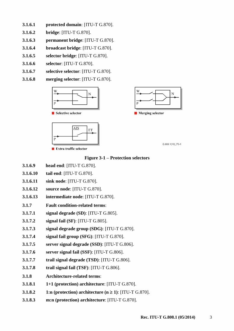
3.1.6.6 selector: [ITU-T G.870].
3.1.6.7 selective selector: [ITU-T G.870].
3.1.6.8 merging selector: [ITU-T G.870].
Figure 3-1 – Protection selectors
3.1.6.9 head end: [ITU-T G.870].
3.1.6.10 tail end: [ITU-T G.870].
3.1.6.11 sink node: [ITU-T G.870].
3.1.6.12 source node: [ITU-T G.870].
3.1.6.13 intermediate node: [ITU-T G.870].
3.1.7 Fault condition-related terms:
3.1.7.1 signal degrade (SD): [ITU-T G.805].
3.1.7.2 signal fail (SF): [ITU-T G.805].
3.1.7.3 signal degrade group (SDG): [ITU-T G.870].
3.1.7.4 signal fail group (SFG): [ITU-T G.870].
3.1.7.5 server signal degrade (SSD): [ITU-T G.806].
3.1.7.6 server signal fail (SSF): [ITU-T G.806].
3.1.7.7 trail signal degrade (TSD): [ITU-T G.806].
3.1.7.8 trail signal fail (TSF): [ITU-T G.806].
3.1.8 Architecture-related terms:
3.1.8.1 1+1 (protection) architecture: [ITU-T G.870].
3.1.8.2 1:n (protection) architecture (n 1): [ITU-T G.870].
3.1.8.3 m:n (protection) architecture: [ITU-T G.870].

4 Rec. ITU-T G.808.1 (05/2014)
3.1.8.4 (1:1)n protection architecture: [ITU-T G.870].
3.1.9 External commands-related terms:
3.1.9.1 lockout of protection transport entity #i (LO #i): [ITU-T G.870].
3.1.9.2 lockout of normal traffic signal #i: [ITU-T G.870].
3.1.9.3 clear lockout of normal traffic signal #i: [ITU-T G.870].
3.1.9.4 freeze: [ITU-T G.870].
3.1.9.5 forced switch for normal traffic signal #i (FS #i): [ITU-T G.870].
3.1.9.6 forced switch for null signal (FS #0): [ITU-T G.870].
3.1.9.7 forced switch for extra traffic signal (FS #ExtraTrafficSignalNumber):
[ITU-T G.870].
3.1.9.8 manual switch for normal traffic signal #i (MS #i): [ITU-T G.870].
3.1.9.9 manual switch for null signal (MS #0): [ITU-T G.870].
3.1.9.10 manual switch for extra traffic signal (MS #ExtraTrafficSignalNumber):
[ITU-T G.870].
3.1.9.11 exercise signal #i (EX): [ITU-T G.870].
3.1.9.12 clear (CLR): [ITU-T G.870].
3.1.10 State-related terms:
3.1.10.1 do not revert normal traffic signal #i (DNR #i): [ITU-T G.870].
3.1.10.2 no request (NR): [ITU-T G.870].
3.1.10.3 wait-to-restore normal traffic signal #i (WtR): [ITU-T G.870].
3.1.11 Operation-related terms:
3.1.11.1 revertive (protection) operation: [ITU-T G.870].
3.1.11.2 non-revertive (protection) operation: [ITU-T G.870].
3.1.12 Signal-related terms:
3.1.12.1 traffic signal: [ITU-T G.870].
3.1.12.2 normal traffic signal: [ITU-T G.870].
3.1.12.3 extra traffic signal: [ITU-T G.870].
3.1.12.4 null signal: [ITU-T G.870].
3.1.13 Switching-related terms:
3.1.13.1 bidirectional (protection) switching: [ITU-T G.780].
3.1.13.2 unidirectional (protection) switching: [ITU-T G.780].
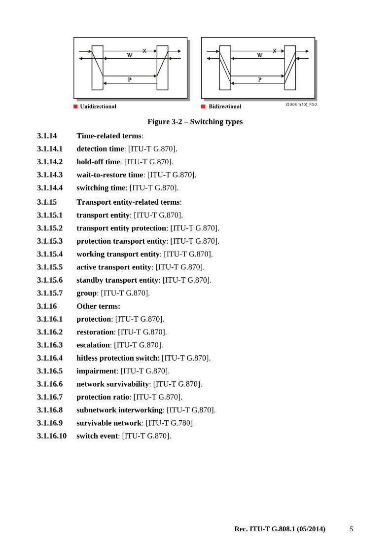
Rec. ITU-T G.808.1 (05/2014) 5
Figure 3-2 – Switching types
3.1.14 Time-related terms:
3.1.14.1 detection time: [ITU-T G.870].
3.1.14.2 hold-off time: [ITU-T G.870].
3.1.14.3 wait-to-restore time: [ITU-T G.870].
3.1.14.4 switching time: [ITU-T G.870].
3.1.15 Transport entity-related terms:
3.1.15.1 transport entity: [ITU-T G.870].
3.1.15.2 transport entity protection: [ITU-T G.870].
3.1.15.3 protection transport entity: [ITU-T G.870].
3.1.15.4 working transport entity: [ITU-T G.870].
3.1.15.5 active transport entity: [ITU-T G.870].
3.1.15.6 standby transport entity: [ITU-T G.870].
3.1.15.7 group: [ITU-T G.870].
3.1.16 Other terms:
3.1.16.1 protection: [ITU-T G.870].
3.1.16.2 restoration: [ITU-T G.870].
3.1.16.3 escalation: [ITU-T G.870].
3.1.16.4 hitless protection switch: [ITU-T G.870].
3.1.16.5 impairment: [ITU-T G.870].
3.1.16.6 network survivability: [ITU-T G.870].
3.1.16.7 protection ratio: [ITU-T G.870].
3.1.16.8 subnetwork interworking: [ITU-T G.870].
3.1.16.9 survivable network: [ITU-T G.780].
3.1.16.10 switch event: [ITU-T G.870].
6 Rec. ITU-T G.808.1 (05/2014)
4 Abbreviations
This Recommendation uses the following abbreviations:
ABR Available Bit Rate
ACL Adaptive Compound Link
ACL-SNCG/I Adaptive Compound Link SNC Group protection with Inherent monitoring
AI Adapted Information
AIS Alarm Indication Signal
AP Access Point
APS Automatic Protection Switching
ATM Asynchronous Transfer Mode
AU Administrative Unit
BER Bit Error Rate
CC Continuity Check
CI Characteristic Information
CIR Committed Information Rate
CL-SNCG/I Compound Link SNC Group protection with Inherent monitoring
CP Connection Point
DBN Dynamic Bandwidth Network
DEG DEGraded
EIR Excessive Information Rate
ET Extra Traffic (signal)
F4 Flow #4 (ATM)
FDI Forward Defect Indication
HO Hold Off
IMG Inverse Multiplexed Group
LCAS Link Capacity Adjustment Scheme
MPLS Multi-Protocol Label Switching
MS Multiplex Section
N Normal (signal)
NE Network Element
NIM Non-Intrusive Monitoring
NR No Request
NUT Non-pre-emptible Unprotected Traffic
OAM Operations, Administration and Maintenance
OCh Optical Channel
OH Overhead
OTN Optical Transport Network

Rec. ITU-T G.808.1 (05/2014) 7
P Protection
PDH Plesiochronous Digital Hierarchy
POH Path OverHead
PP Pointer Processing
PTN Packet Transport Networks
PU Port Unit
RDI Remote Defect Indication
REI Remote Error Indication
RI Remote Information
RS Regenerator Section
SD Signal Degrade
SDG Signal Degrade Group
SDH Synchronous Digital Hierarchy
SEL Selector
SES Severely Errored Second
SF Signal Fail
SFG Signal Fail Group
SIM Survivability of Inverse Multiplexed link connections
SNC Subnetwork Connection
SNC/I Inherently monitored Subnetwork Connection protection
SNC/N Non-intrusively monitored Subnetwork Connection protection
SNC/Ne SNC/N, monitoring of end-to-end OH
SNC/Ns SNC/N, monitoring of sub-layer OH
SNC/S SNCP with Sublayer monitoring
SNC/Ss SNC/S, monitoring of sublayer OH
SNC/T SNCP with Test trail monitoring
SNC/Te SNC/T, monitoring of end-to-end OH
SNC/Ts SNC/T, monitoring of sublayer OH
SNCG Subnetwork Connection Group
SNCG/I SNC Group protection with Inherent monitoring
SNCG/N SNC Group protection with Non-intrusive monitoring
SNCG/S SNC Group protection with Sublayer monitoring
SNCG/T SNC Group protection with Test trail monitoring
SNCP Subnetwork Connection Protection
SOH Section OverHead
SSD Server Signal Degrade
SSF Server Signal Fail
8 Rec. ITU-T G.808.1 (05/2014)
STM-N Synchronous Transport Module, level N
TCP Termination Connection Point
TSD Trail Signal Degrade
TSF Trail Signal Fail
TSI TimeSlot Interchange
TT Trail Termination
TU Tributary Unit
UBR Unspecified Bit Rate
UPSR Unidirectional Path Switch Ring
VC Virtual Channel (ATM)
VCG Virtual Concatenation Group
VC-n Virtual Container-n
VC-n-Xv Virtual concatenation of X virtual containers (of level n)
VC-m Virtual Container-m
VP Virtual Path (ATM)
VPI Virtual Path Identifier
W Working
WTR Wait-to-Restore
5 Conventions
This Recommendation uses the following terms:
– A: Endpoint designation used when describing a protected domain; A is the source end of
protected signals for which switch request signalling is initiated from the other, Z, end.
– Z: Endpoint designation used when describing a protected domain; Z is the end at which
switch request signalling is initiated.
– Sm: lower order virtual container-m (VC-m) layer (n = 11, 12, 2)
– Sn: higher order virtual container-n (VC-n) layer (n = 3, 4, 4-Xc) or lower order VC-3 layer
– Sn-Xv: virtual concatenation of X virtual containers (of level n) (VC-n-Xv) layer
– X, Y, Z: Layer (for non-specified layers) or group size designations
6 Individual and group protection concept
The individual protection concept applies to the situations where it is useful to protect only the part
of the traffic signals that need high reliability. The rest of the traffic signals in the network layer
remain unprotected. This helps to reduce the necessary bandwidth for protection.
The group protection concept applies to the situations where:
1) It is useful to protect a large number (but not all) of the traffic signals transported via the
same server layer trails, with protection times in the same order as individual protection (of
a small set of traffic signals). Fast protection switching is obtained through the treatment of
a logical bundle of transport entities as a single entity after the commencement of
protection actions.
Rec. ITU-T G.808.1 (05/2014) 9
2) The protection of a group of traffic signals that realize a single traffic signal by means of
e.g., virtual concatenation, inverse multiplexing.
The complexity of the protection process is reduced by treating the group of signals as a single
entity, within a single protection process. The status of the working and protection groups is
represented by signal fail group (SFG) and signal degrade group (SDG) indications.
The complexity can be further reduced by the introduction of an additional test signal (transported
over the same server layer trails), of which the signal fail (SF) and signal degrade (SD) indications
are used to represent the status of the group. The disadvantage of this latter complexity reduction
technique is the inability to monitor the individual signals in each group for their connectivity,
continuity and performance. One of these faults within one of the signals in the group will not be
detected, and thus not protected.
7 Architecture types
The protection architecture can be a 1+1, a 1:n, a m:n, or a (1:1)n architecture type.
Possible advantages of the 1+1 architecture include:
1) low complexity
2) possibility to support dual node interconnection of protected subnetworks in the case of
unidirectional switching.
Possible disadvantages of the 1+1 architecture include:
3) 100 per cent extra capacity.
Possible advantages of the 1:n, m:n, (1:1)n architecture include:
1) possibility to provide protection access; the protection transport entity/bandwidth can
transport an extra traffic signal (ET) during periods when the protection transport
entity/bandwidth is not required to transport a normal traffic signal
2) extra capacity restricted to 100/n % or m × 100/n %
3) protection is possible for up to m faults in the case of m:n.
Possible disadvantages of the 1:n, m:n, (1:1)n architecture include:
4) complexity
5) the need for additional sublayer termination functions at ingress and egress points of the
protected domain on each working and protection transport entity in the case of subnetwork
connection (SNC) protection class
6) does not support dual node interconnection of protected subnetworks
7) n 2: each of the n working transport entities must be routed via different facilities and
equipment to prevent the existence of common points of failure that cannot be protected by
the single protection transport entity in a 1:n and (1:1)n architecture.
NOTE 1 – Typically, n+1 alternative paths between two nodes in the network will not be available. As such,
1:n and (1:1)n, with n 2, architectures will not provide adequate protection for the n normal traffic signals
transported normally via the n working transport entities. n = 1 seems to be the only reasonable choice.
NOTE 2 – In asynchronous transfer mode (ATM), protection access is not explicitly required to allow usage
of the normally unused protection bandwidth. Available bit rate (ABR) and unspecified bit rate (UBR) traffic
could use this protection bandwidth by means of an over-subscription of the bandwidth of the server signal
containing the protection transport entity. The ABR/UBR higher layer control mechanism is assumed to
reduce the traffic when the protection is actually used. The ingress/egress nodes of the protection domain do
not have to align with ingress/egress nodes of ABR/UBR traffic. This adds flexibility to the network and
reduces complexity.

10 Rec. ITU-T G.808.1 (05/2014)
7.1 1+1 protection architecture
In the 1+1 architecture type, a protection transport entity is dedicated as a backup facility to the
working transport entity with the normal traffic signal bridged onto the protection transport entity at
the source endpoint of the protected domain. The normal traffic on working and protection transport
entities is transmitted simultaneously to the sink endpoint of the protected domain where a selection
between the working and protection transport entity is made, based on some predetermined criteria,
such as SF and SD indications. See Figure 7-1.
Figure 7-1 – 1+1 protection architecture
7.2 1:n protection architecture
In the 1:n architecture type, a dedicated protection transport entity is a shared backup facility for n
working transport entities. The bandwidth of the protection transport entity should be allocated in
such a way that it may be possible to protect any of the n working transport entities in case the
protection transport entity is available.
When a working transport entity is determined to be impaired, its normal traffic signal must be
transferred from the working to the protection transport entity at both the source and sink endpoints
of the protected domain. It is noted that, when more than one working transport entities is impaired,
only one normal traffic signal can be protected.
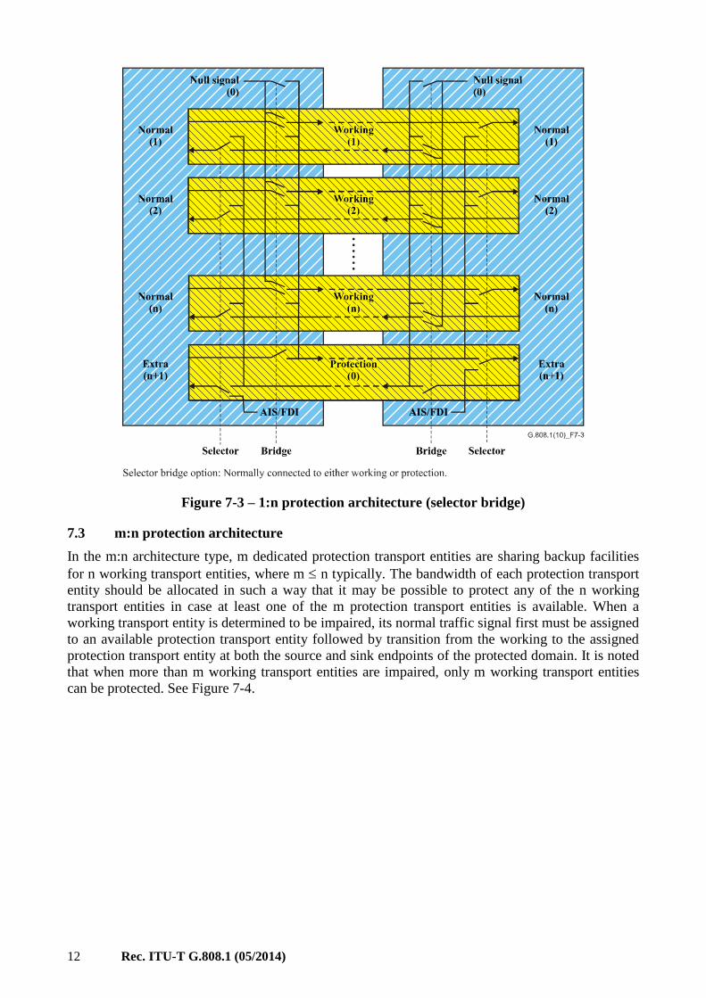
The bridge can be realized in two ways: selector bridge or broadcast bridge. With selector bridge
connectivity (Figure 7-3), the normal traffic signal is connected either to the working transport
entity, or to the protection transport entity. With broadcast bridge connectivity (Figure 7-2) the
normal traffic signal is permanently connected to the working transport entity, and occasionally to
the protection transport entity also. In general, interworking between the two options is guaranteed.

Rec. ITU-T G.808.1 (05/2014) 11
Figure 7-2 – 1:n protection architecture (broadcast bridge)
12 Rec. ITU-T G.808.1 (05/2014)
Figure 7-3 – 1:n protection architecture (selector bridge)
7.3 m:n protection architecture
In the m:n architecture type, m dedicated protection transport entities are sharing backup facilities
for n working transport entities, where m n typically. The bandwidth of each protection transport
entity should be allocated in such a way that it may be possible to protect any of the n working
transport entities in case at least one of the m protection transport entities is available. When a
working transport entity is determined to be impaired, its normal traffic signal first must be assigned
to an available protection transport entity followed by transition from the working to the assigned
protection transport entity at both the source and sink endpoints of the protected domain. It is noted
that when more than m working transport entities are impaired, only m working transport entities
can be protected. See Figure 7-4.

Rec. ITU-T G.808.1 (05/2014) 13
.....
..
G.808.1(14)_F7-4
Working(n)
Protection(m )-1
Protection(0)
Working(2)
Working(1)
Extra(n+1)
Normal(n)
Normal(2)
Normal(1)
Null signal(0)
Extra(n+1)
Normal(2)
Normal(1)
Null signal(0)
Extra
(n+m)
Normal(n)
Extra
(n+m)
Selector Bridge SelectorBridge
Broadcast bridge option: Normally permanently connected to working and occasionally to protection.
AIS/FDI AIS/FDI
Figure 7-4 – m:n protection architecture
7.4 (1:1)n protection architecture
In the (1:1)n protection architecture, n dedicated protection transport entities sharing the same
bandwidth are backup facilities for n working transport entities. The protection bandwidth should be
allocated in such a way that it may be possible to protect any of the n working transport entities in
case the protection transport bandwidth, and the specific protection transport entity associated with
the working transport entity to be switched, is available. When a working transport entity is
determined to be impaired, its normal traffic signal must first be assigned to the associated available
protection transport entity followed by transition from the working to the assigned protection
transport entity at both the source and sink endpoints of the protected domain. It is noted that when
more than one working transport entity is impaired, only one working transport entity can be
protected. See Figure 7-5.
14 Rec. ITU-T G.808.1 (05/2014)
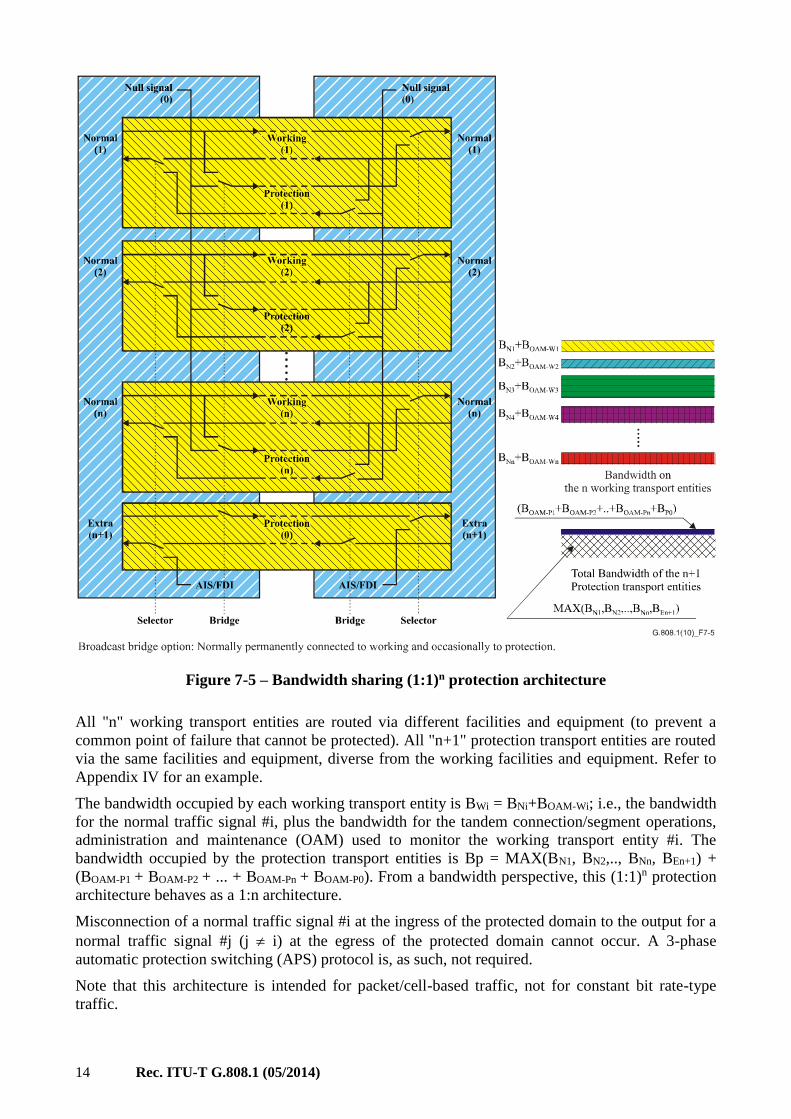
Figure 7-5 – Bandwidth sharing (1:1)n protection architecture
All "n" working transport entities are routed via different facilities and equipment (to prevent a
common point of failure that cannot be protected). All "n+1" protection transport entities are routed
via the same facilities and equipment, diverse from the working facilities and equipment. Refer to
Appendix IV for an example.
The bandwidth occupied by each working transport entity is BWi = BNi+BOAM-Wi; i.e., the bandwidth
for the normal traffic signal #i, plus the bandwidth for the tandem connection/segment operations,
administration and maintenance (OAM) used to monitor the working transport entity #i. The
bandwidth occupied by the protection transport entities is Bp = MAX(BN1, BN2,.., BNn, BEn+1) +
(BOAM-P1 + BOAM-P2 + ... + BOAM-Pn + BOAM-P0). From a bandwidth perspective, this (1:1)n protection
architecture behaves as a 1:n architecture.
Misconnection of a normal traffic signal #i at the ingress of the protected domain to the output for a
normal traffic signal #j (j i) at the egress of the protected domain cannot occur. A 3-phase
automatic protection switching (APS) protocol is, as such, not required.
Note that this architecture is intended for packet/cell-based traffic, not for constant bit rate-type
traffic.

Rec. ITU-T G.808.1 (05/2014) 15
8 Switching types
The protection switching types can be a unidirectional switching type or a bidirectional switching
type.
In unidirectional switching, the switching is complete when the traffic signal (service) is selected
from standby at the end detecting the fault. For the case of the 1+1 architecture, the selector at the
sink end is operated only (without communication with the source end). For the case of the 1:n,
m:n, and (1:1)n architectures, the selector at the sink end, as well as the bridge at the source end, are
operated.
In bidirectional switching, the traffic signal (service) is switched from the active to the standby
transport entity at both ends of the protection span. For the case of the 1+1 architecture, the
selectors at the sink and source ends are operated. For the case of the 1:n, m:n, (1:1)n architectures,
the selectors at the sink and source ends, as well as the bridges at the source and sink ends, are
operated.
NOTE 1 – All switching types, except 1+1 unidirectional switching, require a communications channel
between the two ends of the protected domain; this is called the automatic protection switching (APS)
channel. The APS channel is terminated in the connection functions at each end of the protected domain.
Under bidirectional switching protocols, switching (operating selector and bridge) at only one end is not
allowed. The two ends communicate to initiate transfer of the normal traffic signal. If the priority of the
request of the source end is lower than that of the sink end, or does not exist, the sink end initiates transfer of
the normal traffic signal and the source end follows this transfer.
In the unidirectional switching type, possible advantages include:
1) Unidirectional protection switching is a simple scheme to implement and does not require a
protocol in a 1+1 architecture.
NOTE 2 – Unidirectional switching in a 1:n architecture (typically applied in radio/satellite links)
requires a protocol to operate between the two endpoints of the protected domain.
2) For a 1+1 architecture, unidirectional protection switching can be faster than bidirectional
protection switching because it does not require a protocol.
3) Under multiple failure conditions, there is a greater chance of restoring traffic by protection
switching if unidirectional protection switching is used, than if bidirectional protection
switching is used.
4) Unidirectional switching allows simple realization of a reliable network by means of
cascaded protected subnetworks. Two subnetworks are connected in a dual node
interconnect/dual subnetwork interworking architecture.
In the bidirectional switching type, possible advantages include:
1) With bidirectional protection switching, the same equipment is used for both directions of
transmission after a failure. This means that there will be fewer disruptions in the service
for repair and reversion to the original working path. In unidirectional switching, the
following switches occur:
i) protection switch
ii) forced switch for the direction unaffected by the failure
iii) revertive switch.

16 Rec. ITU-T G.808.1 (05/2014)
In bidirectional switching, only two switches will occur:
i) protection switch
ii) revertive switch.
Each switch will result in one or two severely errored seconds (SESs). Fewer SESs will
result from bidirectional switching.
2) With bidirectional protection switching, if there is a fault in one transport entity of the
network, transmission of both transport entities between the affected nodes is switched to
the alternative direction around the network. No traffic is then transmitted over the faulty
section of the network and so it can be repaired without further protection switching.
3) Bidirectional protection switching is easier to manage because both directions of
transmission use the same equipment along the full length of the transport entity.
4) Bidirectional protection switching maintains equal delays for both directions of
transmission. This may be important where there is a significant imbalance in the length of
the transport entities, e.g., transoceanic links where one transport entity is via a satellite link
and the other is via a cable link.
5) Bidirectional protection switching also has the ability to carry extra traffic on the protection
transport entity.
9 Operation types
The protection operation types can be a non-revertive operation type or a revertive operation type.
In revertive operation, the traffic signal (service) always returns to (or remains on) the working
transport entity if the switch requests are terminated. That is, when the working transport entity has
recovered from the defect, or when the external request is cleared.
In non-revertive operation, the traffic signal (service) does not return to the working transport entity
if the switch requests are terminated.
Some protection schemes are inherently revertive. For other schemes either revertive or non-
revertive operation is possible. An advantage of non-revertive operation is that, in general, it will
have less impact on traffic performance. However, there are situations where revertive operation
may be preferred. Examples of cases where revertive operation may be appropriate are:
1) Where parts of the protection transport entity may be taken to provide capacity to meet a
more urgent need. For example, where the protection transport entity can be taken out of
service to release capacity for use in restoring other traffic.
2) Where the protection transport entity may be subject to frequent rearrangement. For
example, where a network has limited capacity and protection routes are frequently
rearranged to maximize network efficiency when changes occur in the network.
3) Where the protection transport entity is of significantly lower performance than the
working transport entity. For example, where the protection transport entity has a worse
error performance or longer delay than the working transport entity.
4) When an operator needs to know which transport entities are carrying normal traffic in
order to simplify the management of the network.
10 Protocol types
Except for the case of 1+1 unidirectional switching, all protection types require that both ends, A
and Z, of the protected domain coordinate their actions of bridging and selecting. Different
protocols are required according to the type of protection and selector and bridge types. Therefore,
nodes A and Z communicate with each other via the APS channel.

Rec. ITU-T G.808.1 (05/2014) 17
There are two basic requirements for a protection protocol:
1) The prevention of misconnections.
2) The minimization of the number of communication cycles between A and Z ends of the
protected domain, in order to minimize the protection switching time. The communication
may be once (Z A), twice (Z A and A Z), or three times (Z A, A Z and
Z A). This is referred to as 1-phase, 2-phase, and 3-phase protocols, respectively.
The conditions under which the different protocol types can be used are shown in Table 10-1.
Table 10-1 – Protocol types related to protection architectures
and selector/bridge types
Protocol type Types of protection using
the protocol Bridge type Selector type
No protocol 1+1 unidirectional only Permanent Selective
1-phase (1:1)n architectures Selector Selective or merging
1+1 architectures Permanent Selective
2-phase (1:1)n architectures Selector Selective or merging
1+1 architectures Permanent Selective
3-phase All architecture types Any Selective
Selector Merging (cell/packet based
technologies)
In the 3-phase protocol type, possible advantages include:
1) operates in all architecture types
2) prevents a misconnection occurring under all circumstances
3) operates a selector or bridge only after confirmation of priority with the other end of the
protected domain.
In the 3-phase protocol type, possible disadvantages include:
1) triple message exchange necessary between two ends of the protected domain, increasing
the switching time.
In the 2-phase protocol type, possible advantages include:
1) reduced switching time compared to the 3-phase protocol
2) operates in 1+1 and (1:1)n architectures.
In the 1-phase protocol type, possible advantages include:
1) short switching time, due to single message interchange needed between the two ends of
protected domain
2) operates in 1+1 and (1:1)n architectures.
In the 1-phase and 2-phase protocol types, possible disadvantages include:
1) both operate a bridge/selector before priority is confirmed by the other end of a protected
domain. As such, a switch action may have to be reverted and replaced by other
bridge/selector action initiated by the other end.

18 Rec. ITU-T G.808.1 (05/2014)
11 Protection classes and subclasses
11.1 Trail protection
Trail protection is a protection class used to protect a trail across an entire operator's network or
multiple operators' networks. It is a dedicated end-to-end protection architecture, which can be used
in different network structures: meshed networks, rings, etc. As trail protection is a dedicated
protection mechanism, there is no fundamental limitation on the number of network elements (NEs)
within the trails.
Trail protection operates in all combinations of protection architectures, switching and operation.
Trail protection generically protects against faults in the server layer, and connectivity faults and
performance degradations in the client layer.
For the case of trail protection, the adapted information (AI) (i.e., the payload of the network layer's
characteristic information (CI)) is protected. See Figure 11-1.
Figure 11-1 – Generic concept of trail protection
NOTE 1 – As 1:1, 1:n, m:n trail protections are linear protection mechanisms, the normal and extra traffic
trail termination (TT) functions are located in the same NE. In a network application, this implies that the
normal and extra traffic patterns must coincide.
Trail protection does not support network architectures which make use of cascaded protected subnetworks
in the same layer. Consequently, traffic can be restored under single-fault conditions only. To restore traffic
under multiple-fault conditions, SNC protection has to be used, or trail protection has to be supplemented
with protection at server layers.
NOTE 2 – For the case of an 1:1, m:n, or (1:1)n architecture in ATM, the protection trail(s) should contain a
signal that allows accurate monitoring of its status. In normal conditions, in which the normal traffic signal is
transported via the working trail, there is no signal to be transported via protection. If continuity check (CC)
would be inactive, such protection trail will not transport any information under normal fault-free conditions.
When a fault occurs, alarm indication signal (AIS) cells are inserted. When the fault is present for a short
period only (e.g., due to a "physical layer protection action"), the AIS defect detector at the protection trail
endpoint will detect the AIS defect condition for two to three seconds according to the ITU-T I.610 defined
AIS state definition. With CC activated, the AIS defect condition will clear on the receipt of a CC cell, i.e.,
within a period of one second after the traffic interruption was cleared.
NOTE 3 – If trail protection is used at path level, this may result in taking up an additional port in a fabric
compared to SNC protection. This is the case when the protection selector is located in the egress port of the
equipment.

Rec. ITU-T G.808.1 (05/2014) 19
11.1.1 Individual trail protection
Figure 11-2 illustrates the case of 1+1 trail protection and 1:1 trail protection without extra traffic
between ingress and egress of the protected domain between NEs A and Z. Two independent trails
(in layer network Y) exist which act as working and protection transport entities for the (protected)
normal (payload) traffic signal. The TT functions generate/insert and monitor/extract the end-to-end
overhead/OAM information to determine the status of the working and protection transport entities.
APS information is transported over the protection trail, except for the case of 1+1 unidirectional
switching.
The cases of 1:n, m:n and (1:1)n architectures with/without extra traffic are extensions of the
1+1/1:1 architecture, in accordance with the architecture type descriptions in clause 7.
Figure 11-2 – 1+1/1:1 trail protection functional model
11.1.2 Group trail protection
Figure 11-3 illustrates the case of 1+1/1:1 group trail protection between NEs A and Z. In this
example, two times three parallel independent trails (in layer network Y) exist which act as working
and protection transport entity groups for the three (protected) normal (payload) traffic signals. The
three parallel normal traffic signals in the group are protected jointly by the trail protection sublayer
connection function. The TT functions generate/insert and monitor/extract the end-to-end
overhead/OAM information to determine the status of the working and protection transport entities.
APS information is transported over one of the protection trails, except for the case of 1+1
unidirectional switching.
The cases of 1:n, m:n and (1:1)n architectures with/without extra traffic are extensions of the
1+1/1:1 architecture, in accordance with the architecture type descriptions in clause 7.

20 Rec. ITU-T G.808.1 (05/2014)
Figure 11-3 – 1+1/1:1 Group trail protection functional model
Figure 11-4 presents additional detail of this protection connection function's processes. Specific for
group protection is the SFG/SDG logic process. This process "merges" the three individual trail
signal fail (TSF) signals into a single SFG and the individual trail signal degrade (TSD) signals into
a single SDG.
The SFG/SDG logic may operate in different modes:
• W-SFG = W1-TSF or W2-TSF or W3-TSF
P-SFG = P1-TSF or P2-TSF or P3-TSF
• W-SFG = W1-TSF
P-SFG = P1-TSF
• W-SFG = X% of the Wi-TSF signals are active
P-SFG = X% of the Pi-TSF signals are active
• idem for SDG.

Rec. ITU-T G.808.1 (05/2014) 21
Figure 11-4 – SFG/SDG logic within the group protection process
As a result of the large number of tributary slots in some transmission technologies (e.g., ATM),
extra tributary slots in the working and protection server layer signals can be allocated to transport
test signals via test transport entities (Figures 11-5 and 11-6). These test signals (one per working,
one per protection) can be used instead of the SFG, SDG information as described above. The APS
signal is transported via the test protection transport entity.
The SFG/SDG logic operates now as follows:
• W-SFG = Wt-TSF
P-SFG = Pt-TSF
• W-SDG = Wt-TSD
P-SDG = Pt-TSD.
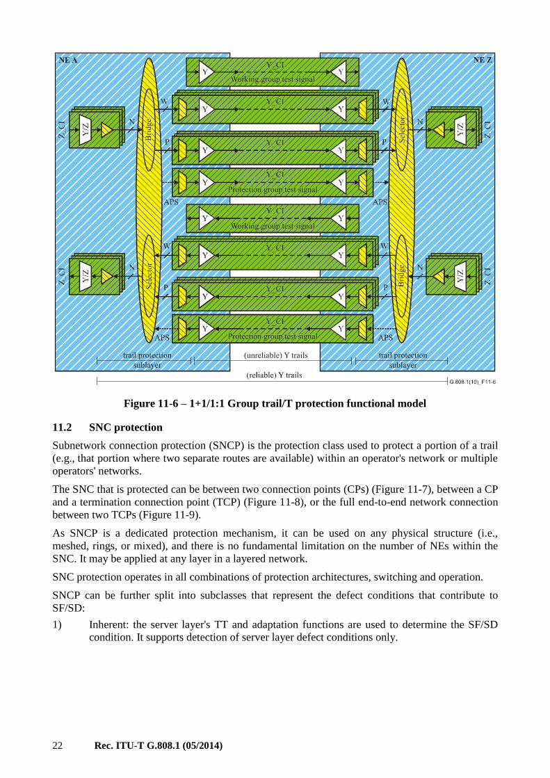
Figure 11-5 – Generic concept of group trail/T protection
22 Rec. ITU-T G.808.1 (05/2014)
Figure 11-6 – 1+1/1:1 Group trail/T protection functional model
11.2 SNC protection
Subnetwork connection protection (SNCP) is the protection class used to protect a portion of a trail
(e.g., that portion where two separate routes are available) within an operator's network or multiple
operators' networks.
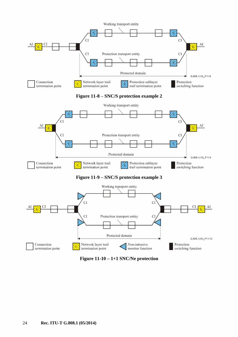
The SNC that is protected can be between two connection points (CPs) (Figure 11-7), between a CP
and a termination connection point (TCP) (Figure 11-8), or the full end-to-end network connection
between two TCPs (Figure 11-9).
As SNCP is a dedicated protection mechanism, it can be used on any physical structure (i.e.,
meshed, rings, or mixed), and there is no fundamental limitation on the number of NEs within the
SNC. It may be applied at any layer in a layered network.
SNC protection operates in all combinations of protection architectures, switching and operation.
SNCP can be further split into subclasses that represent the defect conditions that contribute to
SF/SD:
1) Inherent: the server layer's TT and adaptation functions are used to determine the SF/SD
condition. It supports detection of server layer defect conditions only.

Rec. ITU-T G.808.1 (05/2014) 23
2) Non-intrusive: non-intrusive monitoring (NIM) functions are deployed to determine the
SF/SD condition.
a) End-to-end: Detection of server layer defect conditions, continuity/connectivity defect
conditions in the layer network, and error degradation conditions in the layer network.
The end-to-end overhead/OAM is used.
b) Sublayer: Detection of server layer defect conditions, continuity/connectivity defect
conditions in the layer network, and error degradation conditions in the layer network.
The sublayer overhead/OAM is used.
3) Sublayer: Tandem connection/segment sublayer functions are deployed to determine the
SF/SD condition. It supports detection of server layer defect conditions,
continuity/connectivity defect conditions in the layer network, and error degradation
conditions in the layer network. The sublayer overhead/OAM is used.
In general, SNC protection requires the creation of sublayer trails (tandem connections, segments)
on the working and protection transport entities to distinguish a fault or degradation that occurs "in
front of" from one that occurs "within" the protected domain. When the sublayer trail includes a
single server layer trail, that server layer trail can be used instead (providing inherent monitoring).
If a sublayer trail cannot be created, or a single server layer trail is not available between the ingress
and egress points of the protected domain, SNC protection can be realized by means of dual feeding
the normal traffic signal to both working and protection transport entities, non-intrusive monitoring
both copies of the signal at the egress point and comparing the SF/SD status obtained from both
monitors. If the fault or degradation occurred in front of the protected domain, both working and
protection monitors will discover the impairment and a switch action will not be performed.
Otherwise, only one of the two monitors will detect an SF/SD condition and, with a switch action,
the traffic flow can be restored.
NOTE 1 – For synchronous digital hierarchy (SDH), due to the treatment of administrative unit (AU)/
tributary unit (TU) pointers during server layer TSF conditions, 1+1 inherently monitored subnetwork
connection protection (SNC/I) can be deployed instead of 1+1 non-intrusively monitored subnetwork
connection protection (SNC/N) if only server layer defects are to be protected..
For the case of SNC protection, the CI (i.e., payload and its layer overhead) is protected. See
Figures 11-7 to 11-11.
Figure 11-7 – SNC/S protection example 1
24 Rec. ITU-T G.808.1 (05/2014)
Figure 11-8 – SNC/S protection example 2
Figure 11-9 – SNC/S protection example 3
Figure 11-10 – 1+1 SNC/Ne protection

Rec. ITU-T G.808.1 (05/2014) 25
G.808.1 _F (14) 11-11
Working transport entity
Protection transport entity
Protected domain
Network layer trailtermination point
Connectiontermination point
Protection sublayertermination pointtrail
Protectionswitching function
AI AIE E
E
CICI
CI
CICI
CI
Non-instrusivesubnetwork function
S
S S
Figure 11-11 – 1+1 SNC/Ns protection
SNC protection supports network architectures, which make use of cascaded protected
subnetworks. Such network architectures are able to restore traffic for the case of multiple faults
(one fault per protected subnetwork); refer to Figure 11-12.
G.808.1 _F(14) 11-12
Working transport entity
Protection transport entity
Protected domain 2
Network layertrail endpoint
Connectionpoint
Protectionswitching function
E E
E Protection sublayertrail endpoint
S S
SS
S
Protected domain 1
Working transport entity
Protection transport entity
S
S S
S
Figure 11-12 – Cascaded SNC/S protection
The fault tolerance (and reliability) of the cascaded SNC protected subnetworks is increased when
the interconnection between the subnetworks is duplicated (Figure 11-13), removing the single
point of failure.
G.808.1 _F (10) 11-13
Network layer trail endpointConnection point Protection switching function
E E
E
Figure 11-13 – Cascaded 1+1 SNC protection with fault
tolerant subnetwork interconnects
NOTE 2 – For the case of an 1:1, m:n, or (1:1)n architecture in ATM, the protection SNC(s) should contain a
signal that allows accurate monitoring of its status. In normal conditions, in which the normal traffic signal is
transported via the working SNC, there is no signal to be transported via protection. If the CC is inactive,
such protection SNC will not transport any information under normal fault-free conditions. When a fault
occurs, AIS cells are inserted. When the fault is present for a short period only (e.g., due to a "physical layer
protection action"), the AIS defect detector at the protection segment endpoint will detect the AIS defect
26 Rec. ITU-T G.808.1 (05/2014)
condition for two to three seconds according to the ITU-T I.610 defined AIS state definition. With the CC
activated, the AIS defect condition will clear on the receipt of a CC cell, i.e., within a period of one second
after the traffic interruption was cleared.
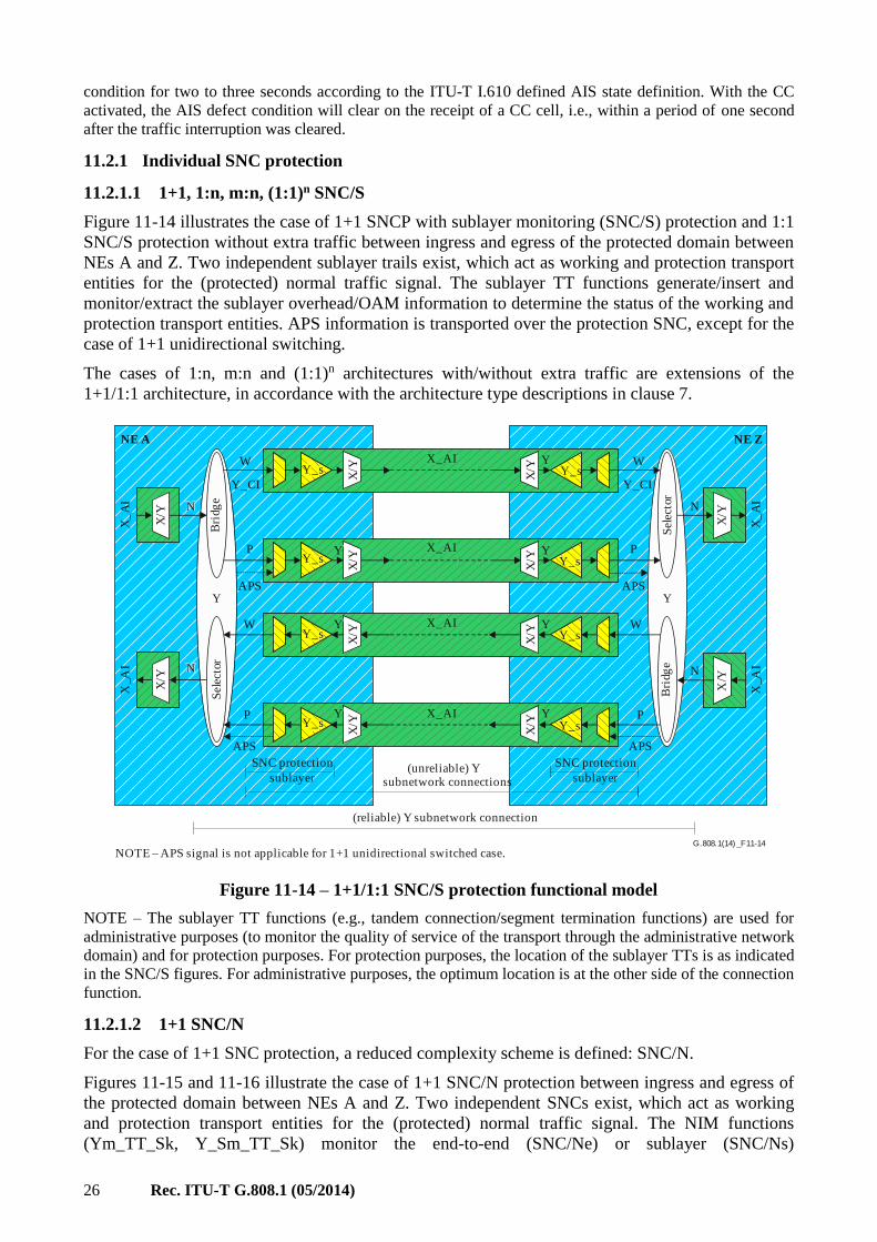
11.2.1 Individual SNC protection
11.2.1.1 1+1, 1:n, m:n, (1:1)n SNC/S
Figure 11-14 illustrates the case of 1+1 SNCP with sublayer monitoring (SNC/S) protection and 1:1
SNC/S protection without extra traffic between ingress and egress of the protected domain between
NEs A and Z. Two independent sublayer trails exist, which act as working and protection transport
entities for the (protected) normal traffic signal. The sublayer TT functions generate/insert and
monitor/extract the sublayer overhead/OAM information to determine the status of the working and
protection transport entities. APS information is transported over the protection SNC, except for the
case of 1+1 unidirectional switching.
The cases of 1:n, m:n and (1:1)n architectures with/without extra traffic are extensions of the
1+1/1:1 architecture, in accordance with the architecture type descriptions in clause 7.
G.808.1 _F(14) 11-14
NE A NE Z
N
W
P
P
APS APS
X_AI
X_AI
X_AI
X_AIY_s
Y
Y Y
Y Y
Y Y
X_
AI
X/Y
N
N
W
W
N
P
P
NOTE APS signal is not applicable for 1+1 unidirectional switched case.
(unreliable) Ysubnetwork connections
(reliable) Y subnetwork connection
SNC protection
sublayer
SNC protection
sublayer
APS APS
Sel
ecto
rB
ridg
e
Sel
ecto
rB
ridg
e
Y_s
Y_s
Y_s
Y_s
Y_s
Y_s
Y_s
Y_CI
W
X/Y
X/Y
X/Y
X_A
I
X_
AI
X_A
I
Y_CI
YY
X/Y
X/Y
X/Y
X/Y
X/Y
X/Y
X/Y
X/Y
Figure 11-14 – 1+1/1:1 SNC/S protection functional model
NOTE – The sublayer TT functions (e.g., tandem connection/segment termination functions) are used for
administrative purposes (to monitor the quality of service of the transport through the administrative network
domain) and for protection purposes. For protection purposes, the location of the sublayer TTs is as indicated
in the SNC/S figures. For administrative purposes, the optimum location is at the other side of the connection
function.
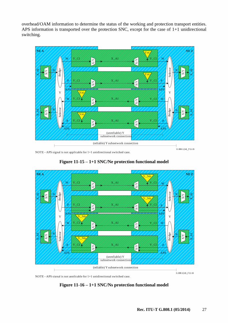
11.2.1.2 1+1 SNC/N
For the case of 1+1 SNC protection, a reduced complexity scheme is defined: SNC/N.
Figures 11-15 and 11-16 illustrate the case of 1+1 SNC/N protection between ingress and egress of
the protected domain between NEs A and Z. Two independent SNCs exist, which act as working
and protection transport entities for the (protected) normal traffic signal. The NIM functions
(Ym_TT_Sk, Y_Sm_TT_Sk) monitor the end-to-end (SNC/Ne) or sublayer (SNC/Ns)
Rec. ITU-T G.808.1 (05/2014) 27
overhead/OAM information to determine the status of the working and protection transport entities.
APS information is transported over the protection SNC, except for the case of 1+1 unidirectional
switching.
G.808.1 _F(14) 11-15
NE A NE Z
N
W
P
P
APS APS
X_AI
X_AI
X_AI
X_AI
X_
AI
X/Y
N
N
W
W
N
P
P
NOTE APS signal is not applicable for 1+1 unidirectional switched case.
(unreliable) Ysubnetwork connections
(reliable) Y subnetwork connection
APS APS
Sel
ecto
rB
ridg
e
Sel
ecto
rB
ridg
e
Ym
W
X/Y
X/Y
X/Y
X_A
I
X_
AI
X_A
I
Y_CI
YY
Y_CI
Ym
Y_CI
Ym
Y_CI
Ym
Y_CI
Y_CI
Y_CI
Y_CI
X/Y
X/Y
X/Y
X/Y
X/Y
X/Y
X/Y
X/Y
Figure 11-15 – 1+1 SNC/Ne protection functional model
G.808.1 _F(14) 11-16
NE A NE Z
N
W
P
P
APS APS
X_AI
X_AI
X_AI
X_AI
X_
AI
X/Y
N
N
W
W
N
P
P
NOTE APS signal is not applicable for 1+1 unidirectional switched case.
(unreliable) Ysubnetwork connections
(reliable) Y subnetwork connection
APS APS
Sel
ecto
rB
ridg
e
Sel
ecto
rB
ridg
e
W
X/Y
X/Y
X/Y
X_A
I
X_
AI
X_A
I
Y_CI
YY
Y_CI
Y_CI
Y_CI
Y_CI
Y_CI
Y_CI
Y_CI
X/Y
X/Y
X/Y
X/Y
X/Y
X/Y
X/Y
X/Y
Y_Sm
Y_Sm
Y_Sm
Y_Sm
Figure 11-16 – 1+1 SNC/Ns protection functional model

28 Rec. ITU-T G.808.1 (05/2014)
11.2.1.3 1+1/1:n SNC/I
For the case of 1+1/1:n SNC protection, another reduced complexity scheme is: SNC/I.
Figure 11-17 illustrates the case of 1+1/1:1 SNC/I protection between ingress and egress of the
protected domain between NEs A and Z. Two independent SNCs exist, which act as working and
protection transport entities for the (protected) normal traffic signal. The X/Y adaptation functions
monitor the server layer's adapted information for signal fail, to determine the status of the working
and protection transport entities. APS information is transported over the protection SNC, except
for the case of 1+1 unidirectional switching.
In general SNC/I protection is a protection scheme for a single link connection (spanning one server
layer trail only) as the adaptation functions derive their server signal fail (SSF) and server signal
degrade (SSD) conditions from the server layer trail's TSF/TSD. The TSF status is forwarded as a
client layer AIS/ forward defect indication (FDI) maintenance signal and is not visible as such at
downstream adaptation functions. The TSD information is not forwarded.
An exception exists for SDH VC-n SNC/I protection; SNC/I is able to protect a serial compound
link connection as the AIS maintenance signal is detected in every adaptation function downstream
of the insertion point.
G.808.1 _F(14) 11-17
NE A NE Z
N
W
P
P
APS APS
X_AI
X_AI
X_AI
X_AI
X_
AI
X/Y
N
N
W
W
N
P
P
NOTE APS signal is not applicable for 1+1 unidirectional switched case.
(unreliable) Ysubnetwork connections
(reliable) Y subnetwork connection
APS APS
Sel
ecto
rB
ridg
e
Sel
ecto
rB
ridg
e
Y_CI
W
X/Y
X/Y
X/Y
X_
AI
X_
AI
X_
AI
Y_CI
YY
X/Y
X/Y
X/Y
X/Y
X/Y
X/Y
X/Y
X/Y
Y_CI
Y_CI
Y_CI Y_CI
Y_CI
Y_CI Y_CI
Figure 11-17 – 1+1/1:1 SNC/I protection functional model
11.3 Subnetwork connection group protection
11.3.1 1+1/1:1 SNCG/S protection
Figure 11-18 illustrates the case of 1+1/1:1 Subnetwork connection group (SNCG) protection with
sublayer monitoring (SNCG/S) protection between NEs A and Z. In this example, two times three
parallel independent sublayer trail monitored SNCs exist, which act as working and protection
transport entity groups for the three (protected) normal traffic signals. The three parallel normal
traffic signals in the group are protected jointly by the layer's connection function. The sublayer TT
functions generate/insert and monitor/extract the sublayer overhead/OAM information to determine
the status of the working and protection transport entities. APS information is transported over one
of the protection SNCs, except for the case of 1+1 unidirectional switching.

Rec. ITU-T G.808.1 (05/2014) 29
The cases of 1:n, m:n and (1:1)n architectures with/without extra traffic are extensions of the
1+1/1:1 architecture, in accordance with the architecture type descriptions in clause 7.
G.808.1 _F(14) 11-18
NE A NE Z
N
W
P
P
APS APS
X_AI
X_AI
X_AI
X_AIY_s
Y
Y Y
Y Y
Y Y
X_
AI
N
N
W
W
N
P
P
NOTE APS signal is not applicable for 1+1 unidirectional switched case.
(unreliable) Ysubnetwork connections
(reliable) Y subnetwork connection
SNC protection
sublayer
SNC protection
sublayer
APS APS
Sel
ecto
rB
ridg
e
Sel
ecto
rB
ridg
e
Y_s
Y_s
Y_s
Y_s
Y_s
Y_s
Y_s
Y_CI
WX
/YX
/Y
X/Y
X/Y
X_A
I
X_
AI
X_A
I
Y_CI
YY
X/Y
X/Y
X/Y
X/Y
X/Y
X/Y
X/Y
X/Y
Figure 11-18 – 1+1/1:1 Group SNC/S protection functional model
Figure 11-4 presents additional detail of this protection connection function's processes. Specific for
group protection is the SFG/SDG logic process. This process "merges" the three individual TSF
signals into a single SFG and the individual TSD signals into a single SDG.
The SNC/S SFG/SDG logic may operate in different modes:
• W-SFG = W1-TSF or W2-TSF or W3-TSF; P-SFG = P1-TSF or P2-TSF or P3-TSF
• W-SFG = W1-TSF; P-SFG = P1-TSF
• W-SFG = X% of the Wi-TSF signals are active; P-SFG = X% of the Pi-TSF signals are
active
• idem for SDG.
11.3.2 1+1 SNCG/N protection
Figure 11-19 illustrates the case of 1+1 SNC group protection with non-intrusive monitoring
(SNCG/N) protection between NEs A and Z. In this example, two times three parallel independent
SNCs exist, which act as working and protection transport entity groups for the three (protected)
normal traffic signals. The three parallel normal traffic signals in the group are protected jointly by
the layer's connection function. The NIM functions monitor the end-to-end (SNC/Ne) or sublayer
(SNC/Ns) overhead/OAM information to determine the status of the working and protection
transport entities. APS information is transported over one of the protection SNCs, except for the
case of 1+1 unidirectional switching.

30 Rec. ITU-T G.808.1 (05/2014)
G.808.1 _F(14) 11-19
NE A NE Z
N
W
P
P
APS APS
X_AI
X_AI
X_AI
X_AIX
_AI
X/Y
N
N
W
W
N
P
P
NOTE APS signal is not applicable for 1+1 unidirectional switched case.
(unreliable) Ysubnetwork connections
(reliable) Y subnetwork connection
APS APS
Sel
ecto
rB
rid
ge
Sel
ecto
rB
rid
ge
Ym
W
X/Y
X/Y
X_
AI
X_A
I
Y_CI
YY
Y_CI
Ym
Y_CI
Ym
Y_CI
Ym
Y_CI
Y_CI
Y_CI
Y_CI
X/Y
X/Y
X/Y
X/Y
X/Y
X/Y
X/Y
X/Y
X/Y
X_A
I
Figure 11-19 – 1+1 group SNC/Ne protection functional model
Figure 11-4 presents additional detail of this protection connection function's processes. Specific for
group 1+1 SNC/N protection is the SFG/SDG logic process. This process "merges" the three
individual TSF signals into a single SFG and the individual TSD signals into a single SDG.
The SNC/N SFG/SDG logic may operate in different modes:
• W-SFG = (W1-TSF and not P1-TSF) or (W2-TSF and not P2-TSF) or (W3-TSF and not
P3-TSF)
P-SFG = (P1-TSF and not W1-TSF) or (P2-TSF and not W2-TSF) or (P3-TSF and not
W3-TSF)
• W-SFG = (W1-TSF and not P1-TSF); P-SFG = (P1-TSF and not W1-TSF);
• W-SFG = X% of the (Wi-TSF and not Pi-TSF) signals are active; P-SFG = X% of the
(Pi-TSF and not Wi-TSF) signals are active
• idem for SDG.
For virtual concatenated SDH VC-n signals (VC-n-Xv), the group SF and SD conditions should be
declared as soon as one of the X signals in the group is failed or degraded.
• W-SFG = W1-TSF or W2-TSF or W3-TSF; P-SFG = P1-TSF or P2-TSF or P3-TSF
• idem for SDG.

Rec. ITU-T G.808.1 (05/2014) 31
11.3.3 1+1 SNCG/I protection
Figure 11-20 illustrates the case of 1+1 SNC group protection with inherent monitoring (SNCG/I)
protection between NEs A and Z. In this example, two times three parallel independent SNCs exist,
which act as working and protection transport entity groups for the three (protected) normal traffic
signals. The three parallel normal traffic signals in the group are protected jointly by the layer's
connection function. The X/Y adaptation functions monitor the server layer's adapted information
for signal fail, to determine the status of the working and protection transport entities. APS
information is transported over one of the protection SNCs, except for the case of 1+1
unidirectional switching.
G.808.1 _F(14) 11-20
NE A NE Z
W
P
P
APS APS
X_AI
X_AI
X_AI
X_AI
W
W
P
P
NOTE APS signal is not applicable for 1+1 unidirectional switched case.
(unreliable) Ysubnetwork connections
(reliable) Y subnetwork connection
APS APS
Sel
ecto
rB
ridg
e
Sel
ecto
rB
ridg
e
W Y_CI
YY
X/Y
X/Y
X/Y
X/Y
X/Y
X/Y
X/Y
X/Y
Y_CI
Y_CI
Y_CI Y_CI
Y_CI
Y_CI Y_CI
N
N
X/Y
X_
AI
X/Y
X_
AI
N
X_
AI
X/Y
N
X/Y
X_A
I
Figure 11-20 – 1+1 Group SNC/I protection functional model
Figure 11-4 presents additional detail of this protection connection function's processes. Specific for
1+1 SNCG/I protection is the SFG logic process. This process "merges" the three individual SSF
signals into a single SFG.
The SNC/I SFG logic may operate in different modes:
• W-SFG = (W1-SSF and not P1-SSF) or (W2-SSF and not P2-SSF) or (W3-SSF and not
P3-SSF)
P-SFG = (P1-SSF and not W1-SSF) or (P2-SSF and not W2-SSF) or (P3-SSF and not
W3-SSF)
• W-SFG = (W1-SSF and not P1-SSF); P-SFG = (P1-SSF and not W1-SSF)
• W-SFG = X% of the (Wi-SSF and not Pi-SSF) signals are active; P-SFG = X% of the
(Pi-SSF and not Wi-SSF) signals are active.

32 Rec. ITU-T G.808.1 (05/2014)
For virtual concatenated SDH VC-n signals (VC-n-Xv), the group SF and SD conditions should be
declared as soon as one of the X signals in the group is failed or degraded.
• W-SFG = W1-SSF or W2-SSF or W3-SSF; P-SFG = P1-SSF or P2-SSF or P3-SSF
• idem for SDG.
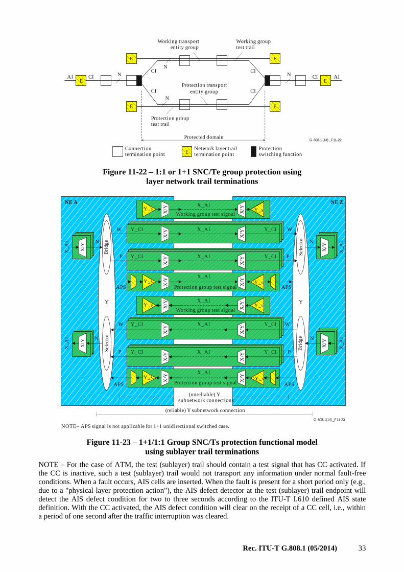
11.3.4 1+1/1:1 group SNC/T protection (SNCG/T)
As a result of the large number of tributary slots in some transmission technologies (e.g., ATM),
extra tributary slots in the working and protection server layer signals can be allocated to transport
test signals via test transport entities (Figures 11-21 and 11-23). These test signals (one per
working, one per protection) can be used instead of the SFG, SDG information as described above.
The APS signal is transported via the test protection transport entity.
The SFG/SDG logic operates now as follows:
• W-SFG = Wt-TSF
P-SFG = Pt-TSF
• W-SDG = Wt-TSD
P-SDG = Pt-TSD.
G.808.1 _F(14) 11-21
Working transportentity group
Protection transportentity group
Protected domain
Network layer trailtermination point
Connectiontermination point
Protectionswitching function
AI AIE E
E
CICI
CI
CI
Sublayer trailtermination point
CI
CI
S S
SS
S
N
N
N N
Working grouptest sublayer trail
Protection grouptest sublayer trail
Figure 11-21 – 1:1 or 1+1 SNC/Ts group protection using sublayer trail terminations
SNC group protection with test trail monitoring (SNCG/T) protection can also use the end-to-end
overhead/OAM to create an end-to-end layer network trail as a test trail (Figure 11-22). Equipment
designs typically locate those layer termination functions at port units (PUs) at the "other side" of
the connection function; i.e., not readily available for group protection test trail purposes.
Rec. ITU-T G.808.1 (05/2014) 33
G.808.1 _F(14) 11-22
Working transportentity group
Protection transport
entity group
Protected domain
Network layer trailtermination point
Connectiontermination point
Protectionswitching function
AI AIE E
E
CICI
CI
CICI
CI
N
N
N N
Working grouptest trail
Protection grouptest trail
E E
E E
Figure 11-22 – 1:1 or 1+1 SNC/Te group protection using
layer network trail terminations
G.808.1 _F(14) 11-23
NE A NE Z
N
W
P
P
APS APS
X_AI
X_AI
X_AI
X_AI
Y_s
X_A
I
X/Y
N
N
W
W
N
P
P
NOTE APS signal is not applicable for 1+1 unidirectional switched case.
(unreliable) Ysubnetwork connections
(reliable) Y subnetwork connection
APS APS
Sel
ecto
rB
ridg
e
Sel
ecto
rB
ridg
e
Y_s
Y_s
Y_s
Y_s
Y_CIW
X/Y
X/Y
X/Y
X_A
I
X_A
IX
_AI
Y_CI
YY
X/Y
X/Y
X/Y
X/Y
X_AI
X_AI
X_AI
X_AI
Y_CIY_CI
Y_CIY_CI
Y_CIY_CI
Protection group test signal
Working group test signal
Working group test signal
Protection group test signalY_s
Y_s
Y_s
X/Y
X/Y
X/Y
X/Y
X/Y
X/Y
X/Y
X/Y
X/Y
X/Y
X/Y
X/Y
Figure 11-23 – 1+1/1:1 Group SNC/Ts protection functional model
using sublayer trail terminations
NOTE – For the case of ATM, the test (sublayer) trail should contain a test signal that has CC activated. If
the CC is inactive, such a test (sublayer) trail would not transport any information under normal fault-free
conditions. When a fault occurs, AIS cells are inserted. When the fault is present for a short period only (e.g.,
due to a "physical layer protection action"), the AIS defect detector at the test (sublayer) trail endpoint will
detect the AIS defect condition for two to three seconds according to the ITU-T I.610 defined AIS state
definition. With the CC activated, the AIS defect condition will clear on the receipt of a CC cell, i.e., within
a period of one second after the traffic interruption was cleared.
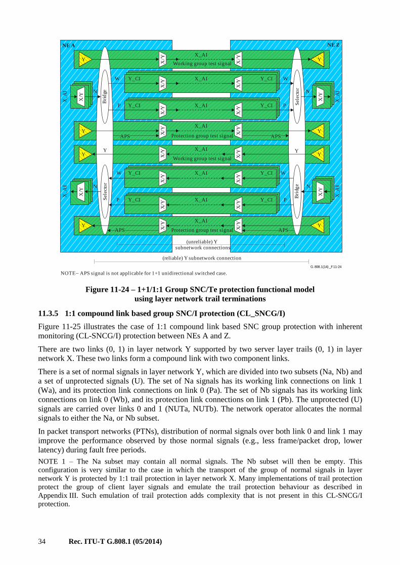
34 Rec. ITU-T G.808.1 (05/2014)
G.808.1 _F(14) 11-24
NE A NE Z
N
W
P
P
APS APS
X_AI
X_AI
X_AI
X_AI
YX
_A
I
X/Y
N
N
W
W
N
P
P
NOTE APS signal is not applicable for 1+1 unidirectional switched case.
(unreliable) Ysubnetwork connections
(reliable) Y subnetwork connection
APS APS
Sel
ecto
rB
rid
ge
Sel
ecto
rB
ridg
e
Y_CIWX
/Y
X/Y
X/Y
X_
AI
X_
AI
X_
AI
Y_CI
YY
X/Y
X/Y
X/Y
X/Y
X_AI
X_AI
X_AI
X_AI
Y_CIY_CI
Y_CIY_CI
Y_CIY_CI
Protection group test signal
Working group test signal
Working group test signal
Protection group test signal
Y
X/Y
X/Y
X/Y
X/Y
X/Y
X/Y
X/Y
X/Y
X/Y
X/Y
X/Y
X/Y
Y Y
Y Y
Y Y
Figure 11-24 – 1+1/1:1 Group SNC/Te protection functional model
using layer network trail terminations
11.3.5 1:1 compound link based group SNC/I protection (CL_SNCG/I)
Figure 11-25 illustrates the case of 1:1 compound link based SNC group protection with inherent
monitoring (CL-SNCG/I) protection between NEs A and Z.
There are two links (0, 1) in layer network Y supported by two server layer trails (0, 1) in layer
network X. These two links form a compound link with two component links.
There is a set of normal signals in layer network Y, which are divided into two subsets (Na, Nb) and
a set of unprotected signals (U). The set of Na signals has its working link connections on link 1
(Wa), and its protection link connections on link 0 (Pa). The set of Nb signals has its working link
connections on link 0 (Wb), and its protection link connections on link 1 (Pb). The unprotected (U)
signals are carried over links 0 and 1 (NUTa, NUTb). The network operator allocates the normal
signals to either the Na, or Nb subset.
In packet transport networks (PTNs), distribution of normal signals over both link 0 and link 1 may
improve the performance observed by those normal signals (e.g., less frame/packet drop, lower
latency) during fault free periods.
NOTE 1 – The Na subset may contain all normal signals. The Nb subset will then be empty. This
configuration is very similar to the case in which the transport of the group of normal signals in layer
network Y is protected by 1:1 trail protection in layer network X. Many implementations of trail protection
protect the group of client layer signals and emulate the trail protection behaviour as described in
Appendix III. Such emulation of trail protection adds complexity that is not present in this CL-SNCG/I
protection.

Rec. ITU-T G.808.1 (05/2014) 35
NOTE 2 – In this example the server layer trails supporting the layer network Y component links are
considered to belong to the same layer network X. This is not a requirement. These server layer trails may
belong to different layer networks; e.g., X and W.
The layer X termination functions monitor the layer X characteristic information for signal fail and
signal degrade, to determine the status of the layer Y component links and carried Wa, Wb, Pa and
Pb link connections. APS information is transported over component link 0.
When layer X trail 0 detects a TSF or TSD condition, then the CL-SNCG/I process in the Y
connection function will switch the set of Nb signals to the set of Pb link connections. Vice versa,
when layer X trail 1 detects a TSF or TSD condition, then the CL-SNCG/I process in the Y
connection function will switch the set of Na signals to the set of Pa link connections.
.....
....
......
......
......
.....
....
.....
....
......
......
......
.....
....
......
.....
....
...
...
...
...
...
...
...
...
...
...
...
...
...
...
...
...
...
...
...
...
...
...
...
...
...
...
...
...
...
...
...
G.808.1(14)_F11-25
Sel
ecto
rB
ridg
e
X/Y
X/Y
X/Y
X/Y
Y
NE AY_CI
Y_CI
Y_CI
Y_CI
Y_CI
Wb
Wb
Pb
Pb
Pa
Pa
Wa
Wa
NUTb
NUTb
APS
APS
NUTa
NUTa
Na
Na
Y_CI
Nb
Nb
U
XX
XX
Sel
ecto
rB
rid
ge
X/Y
X/Y
X/Y
X/Y
Y
NE Z
(reliable) Y layer subnetwork connections
(unreliable) Y layer link connections
Y_CI
Y_CI
Y_CI
Y_CI
Y_CI
Wb
Wb
Pb
Pb
Pa
Pa
Wa
Wa
NUTb
NUTb
APS
APS
NUTa
NUTa
Na
Na
Y_CI
Nb
Nb
X layer network trail 1
X layer network trail 0
X layer network trail 0
X layer network trail 1
Na
Na
Nb
Nb
Wa
Wa
Wb
Wb
Pa
Pa
Pb
Pb
Selectorbridge
Selectiveselector
Y layer LINK 1
Y layer LINK 0
Y layer LINK 1
Y layer LINK 0
UY layer compound Link
Y layer compound Link
X_CI
X_CI
X_CI
X_CI
XX
XX
Figure 11-25 – 1:1 Compound link subnetwork connection group protection
with inherent monitoring (CL-SNCG/I) functional model
11.3.6 Adaptive CL-SNCG/I
Figure 11-26 illustrates the case of compound link based ACL-SNCG/I protection between NEs A
and Z.
There are m+1 links (0, 1, .., m) in layer network Y supported by m+1 server layer trails (0, 1, .., m)
in layer network X. These m+1 links form a compound link including m+1 component links.
There is a set of normal signals Ni (i=1, 2, .., n) in layer network Y that are transported via the
compound link. The distribution of the set of normal signals over the m+1 component links is
controlled by the ACL-SNCG/I connection manager process on the basis of the status of the egress
component links, bandwidth (i.e., CIR/EIR) of the component links, bandwidth (CIR/EIR) of the
normal signals, priority of the normal signals and external commands.

36 Rec. ITU-T G.808.1 (05/2014)
Each of the component links (link j (j=0, .., m)) supports a link connection for each of the normal
signals Ni (i=1, 2, .., n). This link connection is identified as LjCi (see Figure 11-26). The
distributor connects each Ni signal with exactly one of the LjCi link connections in the component
link.
The distribution decision is made at the head end and is not communicated to the tail end. The
collector process at the tail end merges the traffic from all L0Ci to LmCi and applies this to output
Ni (i=1, 2, .., n).
For the case in which link j experiences an SF or SD condition, AIS is inserted towards each layer
Y CP. As long as at least one component link is not experiencing an SF/SD condition, traffic for Ni
will be carried over a non-failed component link and AIS should not be present in the signal. The
collector process will block such AIS or other unexpected frames from a failed component link
under control of the link's trail signal fail (TSFj) or trail signal degrade (TSDj) indication. When all
component links have failed, AIS generated by the last component link endpoint will be passed
through the collector process towards the Ni output ports.
For the case in which one or more component links have failed, the remaining available bandwidth
of the compound link may be less than the bandwidth of the set of normal signals. The distribution
process will now block forwarding a subset of the normal signals, i.e., those with lowest priority, so
as not to exceed the available capacity on the compound link. The distribution process will insert
AIS in those blocked normal signals and transport them over their link connections on the available
component links to suppress downstream continuity alarms.
The layer X termination functions monitor the layer X CI for SF and SD to determine the status of
the layer Y component links.
The SF/SD status of each component link is known at the tail end, while it is used at the head end
by the distribution process. The tail end uses the adaptive compound link (ACL)-APS OAM to send
the status to the head end. The head end sends this ACL-APS OAM in all layer X trails, the tail end
reads this ACL-APS OAM from one of the operational (non-failed) layer X trails.
The operator may temporarily disable one or more component links in the compound link; e.g., for
maintenance purposes. The operator may increase the set of component links in the compound link.
The operator may permanently decrease the set of component links in the compound link.
NOTE – In this example the server layer trails supporting the layer network Y component links are
considered to belong to the same layer network X. This is not a requirement. These server layer trails may
belong to different layer networks; e.g., V, W and X.
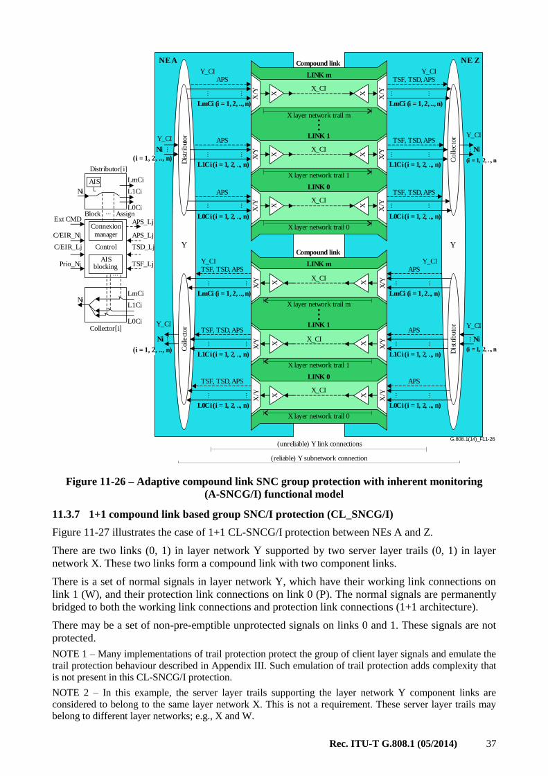
Rec. ITU-T G.808.1 (05/2014) 37
G.808.1(14)_F11-26
X/Y
X/Y
X/Y
L0Ci (i = 1, 2, .., n)
L1Ci (i = 1, 2, .., n)
LmCi (i = 1, 2, .., n)
L0Ci (i = 1, 2, .., n)
L1Ci (i = 1, 2, .., n)
LmCi (i = 1, 2.., n)
TSF, TSD, APS
TSF, TSD, APS
TSF, TSD, APS
APS
APS
APSY_CI
XX
X
Col
lect
or
Dis
trib
uto
r
X/Y
X/Y
X/Y
(reliable) Y subnetwork connection
(unreliable) Y link connections
X layer network trail 0
X layer network trail 1
X layer network trail m
Connexionmanager
LINK 0
LINK 1
LINK m
X_CI
X_CI
X_CI
XX
X
Y_CI
X/Y
X/Y
X/Y
L0Ci (i = 1, 2, .., n)
L1Ci (i = 1, 2, .., n)
LmCi (i = 1, 2, .., n)
L0Ci (i = 1, 2, .., n)
L1Ci (i = 1, 2, .., n)
LmCi (i = 1, 2, .., n)
TSF, TSD, APS
TSF, TSD, APS
TSF, TSD, APS
APS
APS
APSY_CI
XX
X
Coll
ecto
r
Dis
trib
uto
r
X/Y
X/Y
X/Y
X layer network trail 0
X layer network trail 1
X layer network trail m
LINK 0
LINK 1
LINK m
X_CI
X_CI
X_CI
XX
X
Y_CI
Y_CI
Y_CI
Compound link
Compound link
(i = 1, 2, .., n)
Y_CI
Y_CI
Control
AISblocking
Distributor[i]
LmCi
LmCi
L1Ci
L1Ci
L0Ci
L0Ci
AIS
Ni
Ni
AssignBlockAPS_LjExt CMD
APS_LjC/EIR_Ni
TSD_LjC/EIR_Lj
TSF_LjPrio_Ni
Collector[i]
Y Y
NE A NE Z
Ni
(i = 1, 2, .., n)
Ni
(i = 1, 2, .., n)
Ni
(i = 1, 2, .., n)
Ni
Figure 11-26 – Adaptive compound link SNC group protection with inherent monitoring
(A-SNCG/I) functional model
11.3.7 1+1 compound link based group SNC/I protection (CL_SNCG/I)
Figure 11-27 illustrates the case of 1+1 CL-SNCG/I protection between NEs A and Z.
There are two links (0, 1) in layer network Y supported by two server layer trails (0, 1) in layer
network X. These two links form a compound link with two component links.
There is a set of normal signals in layer network Y, which have their working link connections on
link 1 (W), and their protection link connections on link 0 (P). The normal signals are permanently
bridged to both the working link connections and protection link connections (1+1 architecture).
There may be a set of non-pre-emptible unprotected signals on links 0 and 1. These signals are not
protected.
NOTE 1 – Many implementations of trail protection protect the group of client layer signals and emulate the
trail protection behaviour described in Appendix III. Such emulation of trail protection adds complexity that
is not present in this CL-SNCG/I protection.
NOTE 2 – In this example, the server layer trails supporting the layer network Y component links are
considered to belong to the same layer network X. This is not a requirement. These server layer trails may
belong to different layer networks; e.g., X and W.
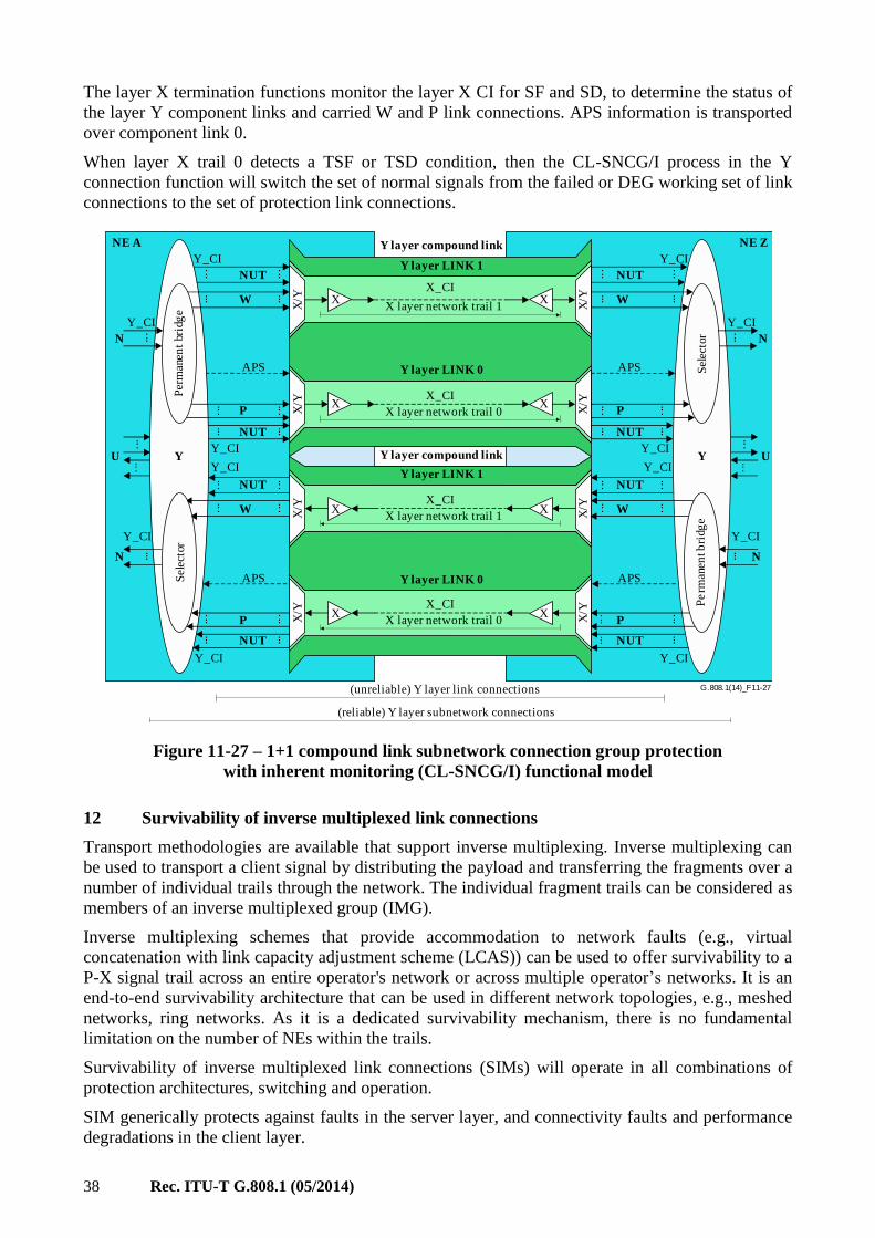
38 Rec. ITU-T G.808.1 (05/2014)
The layer X termination functions monitor the layer X CI for SF and SD, to determine the status of
the layer Y component links and carried W and P link connections. APS information is transported
over component link 0.
When layer X trail 0 detects a TSF or TSD condition, then the CL-SNCG/I process in the Y
connection function will switch the set of normal signals from the failed or DEG working set of link
connections to the set of protection link connections.
U U
Y_CI
NUT
NUT
W
P
P
NUT
W
NUT
Pe
rman
ent b
rig
ed
Sel
ecto
r
APS
APS
Y
Y_CI
Y_CI
Y_CI
Y_CI
Y_CI
N
N
NE A Y layer compound link
Y layer compound link
Y_CI
NUT
NUT
W
P
P
NUT
W
NUT
Per
man
ent
bri
ge
dS
elec
tor
Y layer LINK 1
Y layer LINK 0
Y layer LINK 1
Y layer LINK 0
X layer network trail 1
X layer network trail 0
X layer network trail 1
X layer network trail 0
X_CI
X_CI
X_CI
X_CI
X
X
X
X
X
X
X
X
X/Y
X/Y
X/Y
X/Y
X/Y
X/Y
X/Y
X/Y
APS
APS
Y
Y_CI
Y_CI
Y_CI
Y_CI
Y_CI
N
N
NE Z
(unreliable) Y layer link connections
(reliable) Y layer subnetwork connections
G.808.1(14)_F11-27
...
...
...
...
......... ...
...
...
...
...
...
...
...
.....
.
.....
.
...
...
...
...
...
...
...
...
...
...
...
...
...
... ...
...
...
...
... ...
...
Figure 11-27 – 1+1 compound link subnetwork connection group protection
with inherent monitoring (CL-SNCG/I) functional model
12 Survivability of inverse multiplexed link connections
Transport methodologies are available that support inverse multiplexing. Inverse multiplexing can
be used to transport a client signal by distributing the payload and transferring the fragments over a
number of individual trails through the network. The individual fragment trails can be considered as
members of an inverse multiplexed group (IMG).
Inverse multiplexing schemes that provide accommodation to network faults (e.g., virtual
concatenation with link capacity adjustment scheme (LCAS)) can be used to offer survivability to a
P-X signal trail across an entire operator's network or across multiple operator’s networks. It is an
end-to-end survivability architecture that can be used in different network topologies, e.g., meshed
networks, ring networks. As it is a dedicated survivability mechanism, there is no fundamental
limitation on the number of NEs within the trails.
Survivability of inverse multiplexed link connections (SIMs) will operate in all combinations of
protection architectures, switching and operation.
SIM generically protects against faults in the server layer, and connectivity faults and performance
degradations in the client layer.
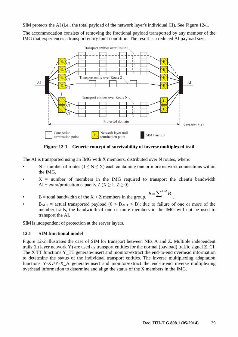
Rec. ITU-T G.808.1 (05/2014) 39
SIM protects the AI (i.e., the total payload of the network layer's individual CI). See Figure 12-1.
The accommodation consists of removing the fractional payload transported by any member of the
IMG that experiences a transport entity fault condition. The result is a reduced AI payload size.
Figure 12-1 – Generic concept of survivability of inverse multiplexed trail
The AI is transported using an IMG with X members, distributed over N routes, where:
• N = number of routes (1 ≤ N ≤ X) each containing one or more network connections within
the IMG.
• X = number of members in the IMG required to transport the client's bandwidth
AI + extra/protection capacity Z (X ≥ 1, Z ≥ 0).
• B = total bandwidth of the X + Z members in the group.
ZX
i iBB.
• BACT = actual transported payload (0 ≤ BACT ≤ B); due to failure of one or more of the
member trails, the bandwidth of one or more members in the IMG will not be used to
transport the AI.
SIM is independent of protection at the server layers.
12.1 SIM functional model
Figure 12-2 illustrates the case of SIM for transport between NEs A and Z. Multiple independent
trails (in layer network Y) are used as transport entities for the normal (payload) traffic signal Z_CI.
The X TT functions Y_TT generate/insert and monitor/extract the end-to-end overhead information
to determine the status of the individual transport entities. The inverse multiplexing adaptation
functions Y-Xv/Y-X_A generate/insert and monitor/extract the end-to-end inverse multiplexing
overhead information to determine and align the status of the X members in the IMG.
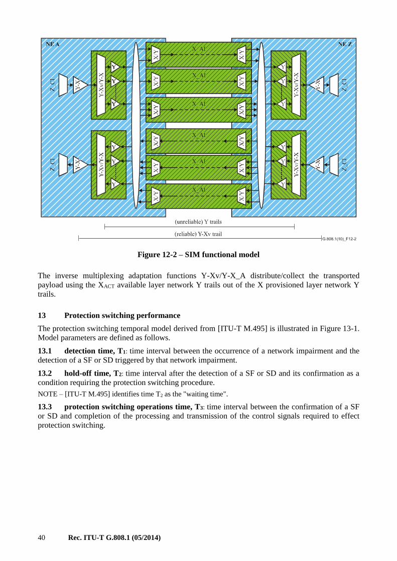
40 Rec. ITU-T G.808.1 (05/2014)
Figure 12-2 – SIM functional model
The inverse multiplexing adaptation functions Y-Xv/Y-X_A distribute/collect the transported
payload using the XACT available layer network Y trails out of the X provisioned layer network Y
trails.
13 Protection switching performance
The protection switching temporal model derived from [ITU-T M.495] is illustrated in Figure 13-1.
Model parameters are defined as follows.
13.1 detection time, T1: time interval between the occurrence of a network impairment and the
detection of a SF or SD triggered by that network impairment.
13.2 hold-off time, T2: time interval after the detection of a SF or SD and its confirmation as a
condition requiring the protection switching procedure.
NOTE – [ITU-T M.495] identifies time T2 as the "waiting time".
13.3 protection switching operations time, T3: time interval between the confirmation of a SF
or SD and completion of the processing and transmission of the control signals required to effect
protection switching.
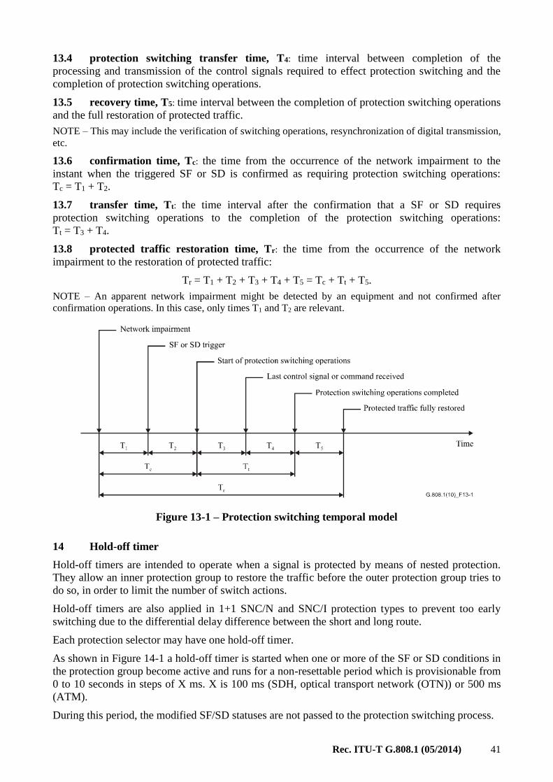
Rec. ITU-T G.808.1 (05/2014) 41
13.4 protection switching transfer time, T4: time interval between completion of the
processing and transmission of the control signals required to effect protection switching and the
completion of protection switching operations.
13.5 recovery time, T5: time interval between the completion of protection switching operations
and the full restoration of protected traffic.
NOTE – This may include the verification of switching operations, resynchronization of digital transmission,
etc.
13.6 confirmation time, Tc: the time from the occurrence of the network impairment to the
instant when the triggered SF or SD is confirmed as requiring protection switching operations:
Tc = T1 + T2.
13.7 transfer time, Tt: the time interval after the confirmation that a SF or SD requires
protection switching operations to the completion of the protection switching operations:
Tt = T3 + T4.
13.8 protected traffic restoration time, Tr: the time from the occurrence of the network
impairment to the restoration of protected traffic:
Tr = T1 + T2 + T3 + T4 + T5 = Tc + Tt + T5.
NOTE – An apparent network impairment might be detected by an equipment and not confirmed after
confirmation operations. In this case, only times T1 and T2 are relevant.
Figure 13-1 – Protection switching temporal model
14 Hold-off timer
Hold-off timers are intended to operate when a signal is protected by means of nested protection.
They allow an inner protection group to restore the traffic before the outer protection group tries to
do so, in order to limit the number of switch actions.
Hold-off timers are also applied in 1+1 SNC/N and SNC/I protection types to prevent too early
switching due to the differential delay difference between the short and long route.
Each protection selector may have one hold-off timer.
As shown in Figure 14-1 a hold-off timer is started when one or more of the SF or SD conditions in
the protection group become active and runs for a non-resettable period which is provisionable from
0 to 10 seconds in steps of X ms. X is 100 ms (SDH, optical transport network (OTN)) or 500 ms
(ATM).
During this period, the modified SF/SD statuses are not passed to the protection switching process.
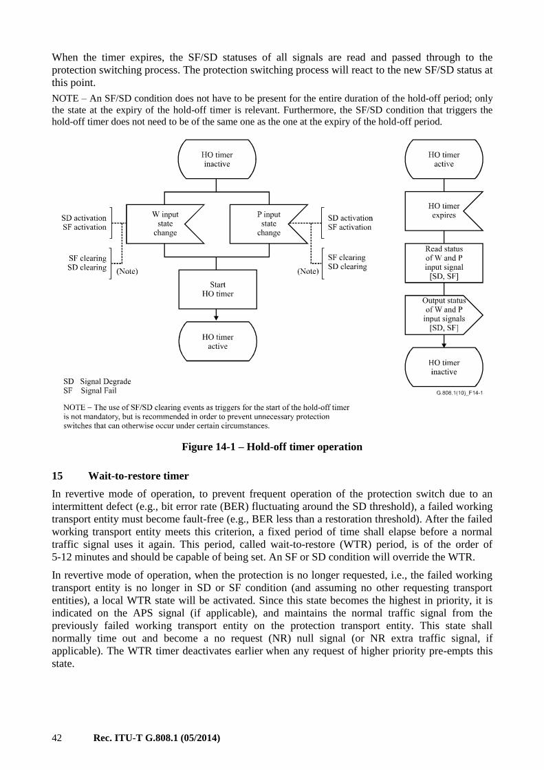
42 Rec. ITU-T G.808.1 (05/2014)
When the timer expires, the SF/SD statuses of all signals are read and passed through to the
protection switching process. The protection switching process will react to the new SF/SD status at
this point.
NOTE – An SF/SD condition does not have to be present for the entire duration of the hold-off period; only
the state at the expiry of the hold-off timer is relevant. Furthermore, the SF/SD condition that triggers the
hold-off timer does not need to be of the same one as the one at the expiry of the hold-off period.
Figure 14-1 – Hold-off timer operation
15 Wait-to-restore timer
In revertive mode of operation, to prevent frequent operation of the protection switch due to an
intermittent defect (e.g., bit error rate (BER) fluctuating around the SD threshold), a failed working
transport entity must become fault-free (e.g., BER less than a restoration threshold). After the failed
working transport entity meets this criterion, a fixed period of time shall elapse before a normal
traffic signal uses it again. This period, called wait-to-restore (WTR) period, is of the order of
5-12 minutes and should be capable of being set. An SF or SD condition will override the WTR.
In revertive mode of operation, when the protection is no longer requested, i.e., the failed working
transport entity is no longer in SD or SF condition (and assuming no other requesting transport
entities), a local WTR state will be activated. Since this state becomes the highest in priority, it is
indicated on the APS signal (if applicable), and maintains the normal traffic signal from the
previously failed working transport entity on the protection transport entity. This state shall
normally time out and become a no request (NR) null signal (or NR extra traffic signal, if
applicable). The WTR timer deactivates earlier when any request of higher priority pre-empts this
state.

Rec. ITU-T G.808.1 (05/2014) 43
16 Automatic protection switching signal
An automated protection switching (APS) signal is used to synchronize the actions at the A and Z
ends of the protected domain. Communicated are:
– request/state type
– requested signal
– bridged signal
– protection configuration.
The request/state type information identifies the highest priority fault condition, external command
or protection process state.
The requested and bridged signal information when transported in an n-bit field identify:
– 0 null signal
– 1… 2n-k-1 normal traffic signal
– 2n-k … 2n-1 extra traffic signal.
Where k is the number of protection transport entities.
The protection configuration information identifies:
– use of an APS channel
– protection architecture (1+1, 1:n)
– switching type (uni-, bidirectional)
– operation type (non-revertive, revertive).
The APS signal is transported via the APS channel. In principle, it is possible to allocate an APS
channel on every transport entity. Allocation of this channel on a working transport entity, however,
would not provide sufficient survivability; i.e., when the working transport entity would fail,
communication between the two endpoints will fail as well, and protection is not possible.
Therefore the APS channel is allocated to one or more protection transport entities.
17 Non-pre-emptible unprotected traffic
Non-pre-emptible unprotected traffic is one of three traffic classes in (1:1) and (1:1)n protection
schemes, the others being protected traffic and extra traffic. NUT has no protection associated with
it, but cannot be dropped from the network to allow protection of other traffic.
Extra traffic or protection channel access allows the use of the protection entities for additional
traffic during normal operation in (1:1) or (1:1)n architectures. When a protection switch occurs, this
traffic is dropped. Extra traffic provides a cheaper service than either protected traffic or
non-pre-emptible unprotected traffic. It is unrelated to the protected traffic, coming from a different
customer and may be used, for example, to provide additional capacity in response to a major event.
18 Extra traffic (protection) transport entity overhead/OAM
For the case of (1:1)n SNC/S protection with extra traffic, the extra traffic (protection) transport
entity does not require the addition of a sublayer TT. The extra traffic (protection) transport entity
has a dedicated tributary slot within the aggregate signal, separate from the tributary slots of the
protection transport entities used to carry a normal traffic signal.
The status of the extra traffic (protection) transport entity does not impact the protection switching
operation and, as such, it is not required to monitor this transport entity.

44 Rec. ITU-T G.808.1 (05/2014)
19 External commands
The autonomous behaviour of the protection switch process on the fault conditions of its transport
entities can be modified by means of external (switch) commands. That is, an external (switch)
command issues an appropriate external request on to the protection process.
NOTE – Only one external (switch) command can be issued per protection group. External commands which
are pre-empted or denied by other higher priority conditions, states or requests, are discarded.
External commands are defined to allow the following types of actions (refer to clause 3.1.9 for
exact definitions of the external commands):
1) Configuration modifications and maintenance to be performed on the protection group or
its transport entities:
– lockout of protection temporarily disables access to the protection transport entity for
all signals
– forced switch for signal #i temporarily forces signal #i to be routed over the protection
transport entity
– manual switch for signal #i temporarily routes signal #i over the protection transport
entity, unless a fault condition (SF, SD) requires another signal to be routed over this
transport entity.
2) Lockout signals from the protection process:
– lockout of signal #i temporarily disables access to the protection transport entity for
the specific signal
– clear lockout of signal #i.
3) Freeze the protection process:
– freeze temporarily prevents any switch action to be taken and, as such, freezes the
current state. Until the freeze is cleared, additional near-end external commands are
rejected and fault condition changes and received APS messages are ignored.
– clear freeze: When the freeze command is cleared, the state of the protection group is
recomputed based on the fault conditions and received APS message.
4) Testing the protection process and APS channel between the two endpoints:
– exercise is a command to test if the APS communication is operating correctly. It is
lower priority than any "real" switch request.
It is only valid in bidirectional switching, since this is the only place where one can get
a meaningful test by looking for a response. The Exercise command shall be issued
with the same requested and bridged signal numbers of the NR, RR or DNR request
that it replaces.
5) Clearing previous external (switch) command:
– clear clears all switch commands.
19.1 External commands for CL-SNC
For the compound link SNC group protection external commands are defined to allow the following
types of actions:
1) Configuration modifications and maintenance to be performed on the protection group or
its transport entities:
– lockout of protection temporarily disables access to link 0 for the normal signals (Na
and Nb)
– forced switch for signal #i temporarily forces signal #i (i=0: null signals, i=1: normal
signals) to be routed over the link 0 topological component
Rec. ITU-T G.808.1 (05/2014) 45
– manual switch for signal #i temporarily routes signal #i (i=0: null signals, i=1: normal
signals) over the link 0 topological component, unless a fault condition (SF, SD)
requires another signal group to be routed over this topological component.
2) Lockout signals from the protection process:
– lockout of signal #i temporarily disables access to link 0 for the specific signals
– clear lockout of signal #i.
3) Freeze the protection process:
– freeze temporarily prevents any switch action to be taken and, as such, freezes the
current state. Until the freeze is cleared, additional near-end external commands are
rejected and fault condition changes and received APS messages are ignored.
– clear freeze: When the freeze command is cleared, the state of the protection group is
recomputed based on the fault conditions and received APS message.
4) Testing the protection process and APS channel between the two endpoints:
– exercise is a command to test if the APS communication is operating correctly. It is
lower priority than any "real" switch request.
5) Clearing previous external (switch) command:
– clear clears all switch commands.
19.2 External commands for ACL-SNC
For the adaptive compound link SNC group, protection external commands are defined to allow the
following types of actions:
1) Configuration modifications and maintenance to be performed on the protection group or
its transport entities:
– ADD add a composite link to the ACL
– REMOVE #i removes a specific composite link (i) from the ACL
– DO_NOT_USE #i temporarily disables the use of composite link (i) from the ACL.
2) Lockout signals from the protection process:
– lockout of signal #i temporarily disables signal #i to be switched from currently
assigned composite link to any other composite links of the ACL;
– clear lockout of signal #i.
3) Freeze the protection process:
– freeze temporarily prevents any protection switch action to be taken and, as such,
freezes the current state. Until the freeze is cleared, additional near-end external
commands are rejected and fault condition changes and received ACL-APS messages
are ignored.
– clear freeze recompute the state of the ACL protection group based on the fault
conditions and received ACL-APS message.
4) Testing the protection process and ACL-APS channel between the two endpoints:
– exercise is a command to test if the APS communication is operating correctly. It is
lower priority than any "real" switch request.
20 Protection switching process states
The following protection switching process states exist:
46 Rec. ITU-T G.808.1 (05/2014)
Do not revert normal traffic signal #i (DNR #i) – In non-revertive operation, this is used to
maintain a normal traffic signal to be selected from the protection transport entity.
No request (NR) – All normal traffic signals are selected from their corresponding working
transport entities. The protection transport entity carries either the null signal, extra traffic, or a
bridge of the single normal traffic signal in a 1+1 protection group.
Wait-to-restore normal traffic signal #i (WtR) – In revertive operation, after the clearing of an
SF or SD on working transport entity #i, maintains normal traffic signal #i as selected from the
protection transport entity until a WTR timer expires. If the timer expires prior to any other event or
command, the state will be changed to NR. This is used to prevent frequent operation of the SE: in
the case of intermittent failures.
21 Priority
Fault conditions, external commands and protection states are defined to have a relative priority
with respect to each other. Priority is applied to these conditions/command/states locally at each
endpoint and between the two endpoints.
Refer to the specific protection switching Recommendations for these priorities.
22 SF and SD trigger conditions
An SF condition is either a TSF or a SSF, which depends on the protection type.
Figure 22-1 illustrates the defect combination rules. SSF is given by adaptation function specific
defects and AI_TSF. TSF is given by any defect of the layer network trail and CI_SSF.
An SF trigger condition is either directly detected by the TT function of the protected layer
network, or it is passed through one or more layers according to the combination rules of specific
defects, CI_SSF and AI_TSF.
TSD is the only SD trigger condition. It is issued on the detection of dDEG. TSD is always local to
a TT function, i.e., it does not pass layer boundaries.

Rec. ITU-T G.808.1 (05/2014) 47
Figure 22-1 – Combination rules of defects
22.1 Overview of SF conditions
Table 22-1 presents an overview of defects that contribute to SF conditions in several transmission
technologies. Refer to equipment Recommendations (e.g., [ITU-T G.783], [ITU-T G.798],
[ITU-T I.732]) for specific SF specifications.
Table 22-1 – Overview of defects contributing to SF condition
ATM OTN SDH
Continuity defects LOC LOS, LOS-P, LCK, LTC LOS, LTC
Connectivity defects None TIM, OCI TIM, UNEQ
Adaptation defects LCD MSIM, LOM, PLM, LOFLOM LOF, LOM, LOP, PLM
Upstream server layer
defects (Note 1)
AIS FDI, FDI-P AIS
Excessive errored trail EXC (Note 2)
Virtual concatenation
defects (Note 3)
LOM, LOA LOM, LOA
NOTE 1 – Any detected defect causes the generation of an AIS/FDI client layer signal that is transported
downstream. Depending on the specific layer, AIS/FDI may be detected at an adaptation or a TT sink
function.
NOTE 2 – EXC does not contribute to TSF and, therefore, it is only a local trigger condition for the
protected layer network (via TSFprot) and not for any client layer.
NOTE 3 – The virtual concatenation defects are applicable for LCAS only.

48 Rec. ITU-T G.808.1 (05/2014)
22.2 Overview of SD conditions
Table 22-2 presents an overview of defects that contribute to SD conditions in several transmission
technologies. Refer to equipment Recommendations (e.g., [ITU-T G.783], [ITU-T G.798]) for
specific SD specifications.
Table 22-2 – Overview of defects contributing to SD condition
ATM OTN SDH
Digital degradations None DEG DEG
Optical degradations Not applicable ffs (Note) None
NOTE – Thresholds for optical degradations are for further study. Whether defects of the OTM overhead
signal (OOS) contribute to the SD or not is for further study, since the OOS is not yet specified.
NOTE – In the 1:1, 1:n, m:n and (1:1)n protection architectures of PTNs, the detection of SD on the standby
entity cannot be based on the service frames, it can also not be based on the extra traffic because extra traffic
can be added/dropped between the endpoints of the protection entity. Loss measurement (LM) is based on
service frames, so it cannot be used in this case. However, by using a specific bridge at the source SD based
protection can be achieved. Appendix VI describes the solution for supporting SD triggered protection in
PTN.
23 Working and protection allocation
The 1+1 linear protection switching can be used as a protection application on a physical ring. As
the ring is often part of a larger network, and only a portion of the trail traverses the ring; this
application is normally used for subnetwork connection transport entities.
Bidirectional traffic can be engineered in two ways:
• The working transport entities for both directions may follow different physical paths, and
the whole ring may be used. This is called unidirectional path switch ring (UPSR) and is
shown in Figure 23-1. It is defined in synchronous optical network (SONET). In general, it
can be used for SNC/I, SNC/N architectures. It should not be used for SNC/S architectures
and trail protection architectures.
Figure 23-1 – Unidirectional path switch ring (UPSR)
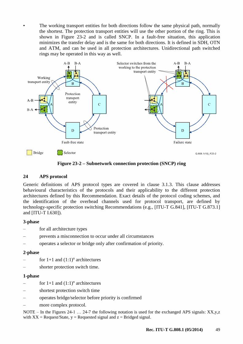
Rec. ITU-T G.808.1 (05/2014) 49
• The working transport entities for both directions follow the same physical path, normally
the shortest. The protection transport entities will use the other portion of the ring. This is
shown in Figure 23-2 and is called SNCP. In a fault-free situation, this application
minimizes the transfer delay and is the same for both directions. It is defined in SDH, OTN
and ATM, and can be used in all protection architectures. Unidirectional path switched
rings may be operated in this way as well.
Figure 23-2 – Subnetwork connection protection (SNCP) ring
24 APS protocol
Generic definitions of APS protocol types are covered in clause 3.1.3. This clause addresses
behavioural characteristics of the protocols and their applicability to the different protection
architectures defined by this Recommendation. Exact details of the protocol coding schemes, and
the identification of the overhead channels used for protocol transport, are defined by
technology-specific protection switching Recommendations (e.g., [ITU-T G.841], [ITU-T G.873.1]
and [ITU-T I.630]).
3-phase
– for all architecture types
– prevents a misconnection to occur under all circumstances
– operates a selector or bridge only after confirmation of priority.
2-phase
– for 1+1 and (1:1)n architectures
– shorter protection switch time.
1-phase
– for 1+1 and (1:1)n architectures
– shortest protection switch time
– operates bridge/selector before priority is confirmed
– more complex protocol.
NOTE – In the Figures 24-1 … 24-7 the following notation is used for the exchanged APS signals: XX,y,z
with XX = Request/State, y = Requested signal and z = Bridged signal.

50 Rec. ITU-T G.808.1 (05/2014)
24.1 1-phase
A means to align the two ends of the protected domain via the exchange of a single message
(Z A).
Applicable for (1:1)n and 1+1 architectures.
The bridge/selector at Z are operated before it is known if Z's condition has priority over the
condition at A.
Figure 24-1 – 1-phase protocol example
G.808.1 _F(10)-Amd.1(12) 24-2
Node A Node Z
SD 1 1,NR , 1 1
SF , 2 2
SF on W2
(A Z)
NodeA s hano request
Se Nt bridge to 2
eS lect N2 from Pend equest for NS r 2
et bridge NS for 2end confirmationS
1
2 2
1
2 2
11
SE
L
BR
SE
L
BR
NR , 2 2
S on WD 1
(A Z)
N2 from P droppedN1 disconnected
N2 from P droppedN1 disconnected
Receive N1
from W1Receive N2from P
Receive N1from W1
Receive N2from P
Accept request elect N from PS 2
Figure 24-2 – 1-phase protocol example for (1:1)n architecture (multiple failures)
24.2 2-phase
A means to align the two ends of the protected domain via the exchange of two messages (Z A,
A Z).
Applicable for (1:1)n architecture and 1+1 architecture.
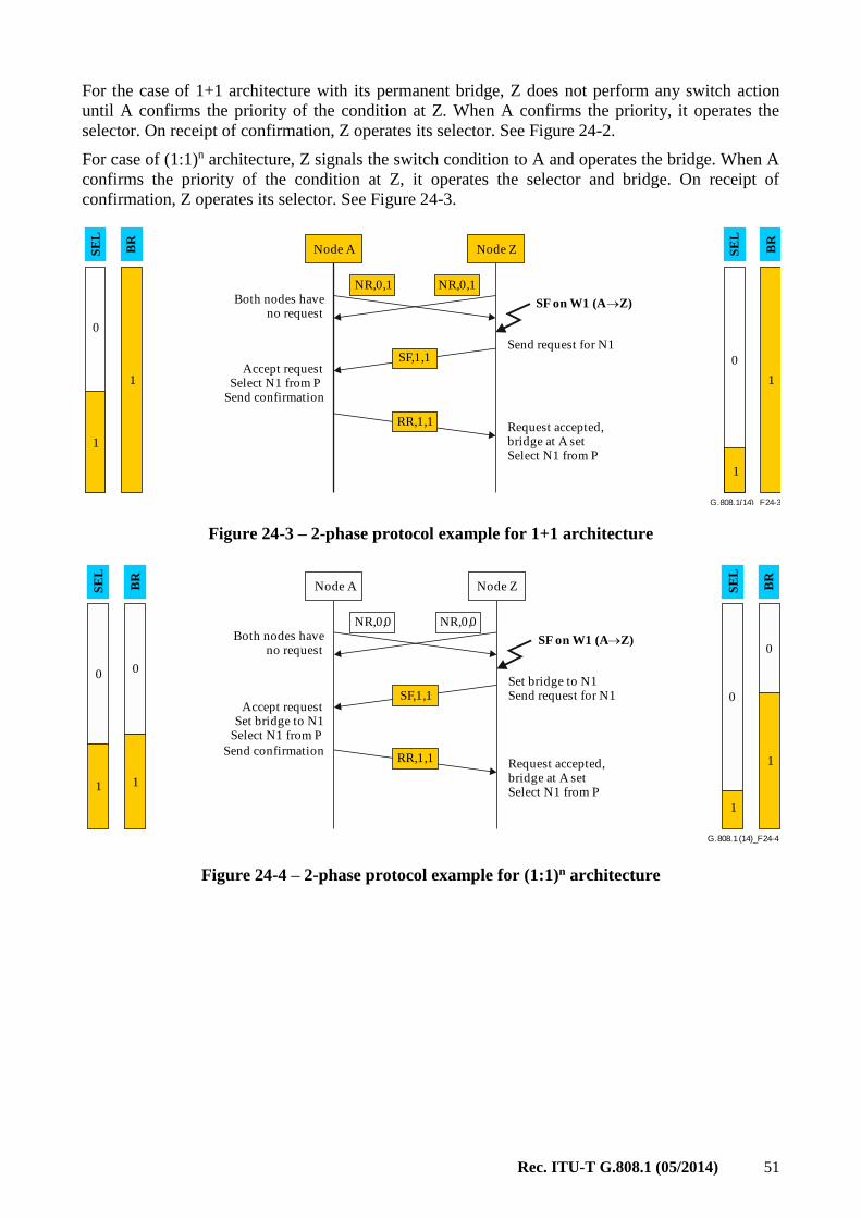
Rec. ITU-T G.808.1 (05/2014) 51
For the case of 1+1 architecture with its permanent bridge, Z does not perform any switch action
until A confirms the priority of the condition at Z. When A confirms the priority, it operates the
selector. On receipt of confirmation, Z operates its selector. See Figure 24-2.
For case of (1:1)n architecture, Z signals the switch condition to A and operates the bridge. When A
confirms the priority of the condition at Z, it operates the selector and bridge. On receipt of
confirmation, Z operates its selector. See Figure 24-3.
G.808.1 _F(14) 24-3
Node A Node Z
NR,0,1NR,0,1
SF,1,1
SF on W1 (A Z)Both nodes have no request
Request accepted,bridge at A setSelect N1 from P
Accept request Select N1 from P
Send confirmation
0
1
1
0
1
1
SE
L
BR
SE
L
BR
RR,1,1
Send request for N1
Figure 24-3 – 2-phase protocol example for 1+1 architecture
G.808.1 _F(14) 24-4
Node A Node Z
NR,0,0NR,0,0
SF,1,1
SF on W1 (A Z)Both nodes have no request
Request accepted,bridge at A setSelect N1 from P
Accept requestSet bridge to N1
Select N1 from P
Send confirmation
0 0
11
0
0
1
1
SE
L
BR
SE
L
BR
RR,1,1
Set bridge to N1Send request for N1
Figure 24-4 – 2-phase protocol example for (1:1)n architecture

52 Rec. ITU-T G.808.1 (05/2014)
G.808.1 _F(14) 24-5
Node A Node Z
SD 1 1,R 1 1R ,
SF , 2 1
SF on W2
(A Z)
NodeA s hano request
Se Nt bridge to 2
end equest for NS r 2
et bridge NS for 2end confirmationS
1
2 2
1
2 2
1
1
SE
L
BR
SE
L
BR
R 2 2R ,
R 2 2R ,
S on WD 1
(A Z)
N2 from P droppedN1 disconnected
Receive N1from W1Receive N2from P
Receive N1from W1
Receive N2from P
N2 from P droppedN1 disconnected
SF , 2 2
S lect N2 from PeSend confirmation
Accept request elect N from PS 2
Figure 24-5 – 2-phase protocol example for (1:1)n architecture (multiple failures)
24.3 3-phase
A means to align the two ends of the protected domain via the exchange of three messages (Z A,
A Z, Z A).
Applicable for 1:n and m:n architectures and for 1+1 architectures with its permanent bridges.
For case of 1:n, m:n architectures, Z does not perform any switch action until A confirms the
priority of the condition at Z. When A confirms the priority, it operates the bridge. On receipt of
confirmation, Z operates its selector and bridge, and indicates the bridge action to A. A finally
operates the selector.
In the case of 1+1 architecture with its permanent bridges, selectors are operated only as described
for case 1:n.

Rec. ITU-T G.808.1 (05/2014) 53
G.808.1 _F(14) 24-6
Node A Node Z
NR,0,0NR,0,0
SF,1,0
SF on W1 (A Z)Both nodes have no request
Request accepted,bridge at A setSelect N1 from PSet bridge for N1Send confirmation
Accept request Set bridge for N1
Send confirmation0
1
1
0
11
SE
L
BR
SE
L
BR
RR,1,1
0
0
Send request for N1
Bridge at Z setSelect N1 from P
SF,1,1
Figure 24-6 – 3-phase protocol example
If an additional protection switching event that overrules the previous one occurs, the node
detecting the event releases its selector before it sends a request for confirmation. See Figure 24-7.
G.808.1 _F(14) 24-7
Node A Node Z
SD 1 1,R 1 1R ,
SF on W2
(A Z)
NodeA s hano request
1
2
2
1
0
2
1
1
SE
L
BR
SE
L
BR
R 2 2R ,
R 2 2R ,
S on WD 1
(A Z)
SF , 2 2
S lect N2 from PeAccept request
et bridge to NS 2Send confirmation
SF , 2 1Release selectorAccept request et bridge to NS 2
Send confirmationand request for N2
2
S lect N2 from Pe
Release selectorend equest for NS r 2
0
Figure 24-7 – 3-phase protocol example (multiple failure)

54 Rec. ITU-T G.808.1 (05/2014)
Appendix I
Implementation of hold-off timer
(This appendix does not form an integral part of this Recommendation.)
An implementation of a hold-off timer may use a counter, which is decremented every X
milliseconds. This quantization introduces an accuracy limitation in realizing the hold-off time.
Figure I.1 presents two examples: it decrements actions every 10 ms [25 ms in the second example].
For a hold-off time of 100 ms, the hold-off counter can be loaded with a value of 10 [4 in the
second example] at the moment of SF/SD occurrence, it decrements at the end of every 10 ms
[25 ms in the second example] decrement period, and expires when reaching the value 0. The hold-
off time realized in this implementation is 95 5 ms [82.5 12.5 ms in the second example].
NOTE – For the case of a decrement period of 100 ms, the 100 ms hold-off time is actually 50 50 ms; i.e.,
between 0 and 100 ms.
Instead of loading with a value of 10 [4 in the second example], the counter can be loaded with 11
[5 in the second example], realizing hold-off times of 105 5 ms [112.5 12.5 ms in the second
example].
The accuracy of this type of hold-off timer is 0.5 times the decrement period.
Figure I.1 – Hold-off timer accuracy
With a 10 ms decrement period, the effect of transfer delay differences between working and
protection transport entities in 1+1 SNC/I and SNC/N protection can be compensated when a
hold-off time of "0" is selected. When the hold-off timer is actually used (instead of disabled), and
the counter is loaded with a value of "2", differential delays of 10 ms can be compensated. Refer to
[ITU-T G.873.1].

Rec. ITU-T G.808.1 (05/2014) 55
Appendix II
Automatic conditions (SF, SD) in group SNC protection
(This appendix does not form an integral part of this Recommendation.)
In 1+1 SNC/N [and SNC/I] protection, SF and SD conditions for the group are the SFG and SDG
SF and SD conditions that are the inputs for the SNC protection process. The logic that computes
the SFG and SDG conditions operates as follows:
• Working SFG = (W-SF1 and not P-SF1) or (W-SF2 and not P-SF2) or etc.
• Protection SFG = (P-SF1 and not W-SF1) or (P-SF2 and not W-SF2) or etc.
• Working SDG = (W-SD1 and not P-SD1) or (W-SD2 and not P-SD2) or etc.
• Protection SDG = (P-SD1 and not W-SD1) or (P-SD2 and not W-SD2) or etc.
This definition of SFG and SDG allows for differentiating between a fault occurring "in front of" or
"within" the protected domain. A fault in front of the protected domain in a single signal will
neither activate W-SFG [SDG] nor P-SFG [SDG], while in both the W-bundle and the P-bundle
SF-i will be activated; the terms "(W-SF-i and not P-SF-i)" and "(P-SF-i and not W-SF-i)" will,
however, be "false".
Figure II.1 – Example of fault within the protected domain
A fault between NE A and B (Figure II.1) will cause W-SFG [or W-SDG] to be activated. If it is a
server signal fault, all signals within the bundle will experience a SF condition. If it is a
connectivity fault, a single signal may experience a SF condition. Both situations will cause W-SFG
to be activated.
If, at the same time, e.g., a disconnection or cable break before NE A is present (impacting one of
the signals in the group), W-SF-i and P-SF-i will be active. When the fault in the protection domain
is a server fault, W-SFG will still be active, and P-SFG is inactive. In the other case (connectivity
fault in the protection domain), the group will be switched if the failed signals in front of and within
the protection domain are different.
NOTE – The special case where all signals have already failed before the protection domain results in
inactive W-SFG and P-SFG. But this special case does not corrupt the operation of the protection process;
there is nothing left to protect.
The errors/faults within the protected domain that cause AIS and DEG defects will do this on all
members of the group at the same moment (assuming it is required that all signals within the group
are transported in the same server signal). As such, the "ORing" of the individual SF and SD
conditions can be used as a trigger.

56 Rec. ITU-T G.808.1 (05/2014)
With respect to a signal loss (e.g., loss of continuity, unequipped), or a connectivity (e.g., trace
identifier mismatch) defect, this group behaviour might not be present. The signals are (in principle)
individually cross-connected in each NE. As such, the ORing of the individual signals will initiate a
protection switch for the group when only one (or a subset) of the signals has a signal loss defect
condition. This is the consequence of the complexity reduction.
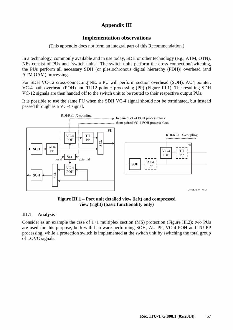
Rec. ITU-T G.808.1 (05/2014) 57
Appendix III
Implementation observations
(This appendix does not form an integral part of this Recommendation.)
In a technology, commonly available and in use today, SDH or other technology (e.g., ATM, OTN),
NEs consist of PUs and "switch units". The switch units perform the cross-connection/switching,
the PUs perform all necessary SDH (or plesiochronous digital hierarchy (PDH)) overhead (and
ATM OAM) processing.
For SDH VC-12 cross-connecting NE, a PU will perform section overhead (SOH), AU4 pointer,
VC-4 path overhead (POH) and TU12 pointer processing (PP) (Figure III.1). The resulting SDH
VC-12 signals are then handed off to the switch unit to be routed to their respective output PUs.
It is possible to use the same PU when the SDH VC-4 signal should not be terminated, but instead
passed through as a VC-4 signal.
Figure III.1 – Port unit detailed view (left) and compressed
view (right) (basic functionality only)
III.1 Analysis
Consider as an example the case of 1+1 multiplex section (MS) protection (Figure III.2); two PUs
are used for this purpose, both with hardware performing SOH, AU PP, VC-4 POH and TU PP
processing, while a protection switch is implemented at the switch unit by switching the total group
of LOVC signals.

58 Rec. ITU-T G.808.1 (05/2014)
Figure III.2 – Mapping of implementation into functional view: Basic operation
According to the functional model, too much functionality is present (Figure III.3); i.e., SOH
processing is expected to be present twice, while AU PP, VC-4 POH and TU PP processing should
be present only once.
Figure III.3 – Mapping of implementation into a functional view: MS protection
With the software, an NE can present the expected functionality; it hides the standby AU PP, VC-4
POH and TU PP processes for the manager.
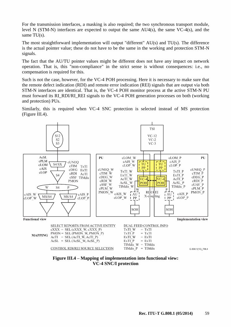
Rec. ITU-T G.808.1 (05/2014) 59
For the transmission interfaces, a masking is also required; the two synchronous transport module,
level N (STM-N) interfaces are expected to output the same AU4(s), the same VC-4(s), and the
same TU(s).
The most straightforward implementation will output "different" AU(s) and TU(s). The difference
is the actual pointer value; these do not have to be the same in the working and protection STM-N
signals.
The fact that the AU/TU pointer values might be different does not have any impact on network
operation. That is, this "non-compliance" in the strict sense is without consequences: i.e., no
compensation is required for this.
Such is not the case, however, for the VC-4 POH processing. Here it is necessary to make sure that
the remote defect indication (RDI) and remote error indication (REI) signals that are output via both
STM-N interfaces are identical. That is, the VC-4 POH monitor process at the active STM-N PU
must forward its RI_RDI/RI_REI signals to the VC-4 POH generation processes on both (working
and protection) PUs.
Similarly, this is required when VC-4 SNC protection is selected instead of MS protection
(Figure III.4).
Figure III.4 – Mapping of implementation into functional view:
VC-4 SNC/I protection

60 Rec. ITU-T G.808.1 (05/2014)
In the case where RDI/REI X-coupling is not implemented, it will not be possible to add
[ITU-T G.826] performance monitoring to networks in which the above protection implementations
are operational. [ITU-T G.826] requires bidirectional (services based) performance monitoring to be
supported. This requires that the far-end information be used. This far-end information must
represent the error/defects detected in the signal path that is actually transporting the client
information.
Unidirectional switching causes each end of the protection span to independently select between
working and protection trail/SNC. If, in the direction A Z, the working VC-4 SNC is selected
and protection VC-4 SNC, in the direction Z A the far-end information extracted at each end is
inserted by the VC-4 POH generator on the standby PU; i.e., the one that is not selected at this end.
If it (now) uses its local RI_RDI/RI_REI signals (instead of its companion RI_RDI/RI_REI
signals), the far-end would receive far-end information that is not related to the actually selected
VC-4.
The bidirectional performance monitoring registers would (in this case) represent the wrong
information; i.e., it cannot be used.
Of course, the same problem exists for the unidirectional (maintenance based) far-end registers.
For the case of a 64 kbit/s routing NE with STM-N interfaces, the same problem will be present at
the VC-12 level.
NOTE – Figures III.3 and III.4 only represent the issue from the RDI/REI viewpoint. These figures do not
show the tandem connection/segment termination or non-intrusive monitor functions that are required to
control the protection switch.
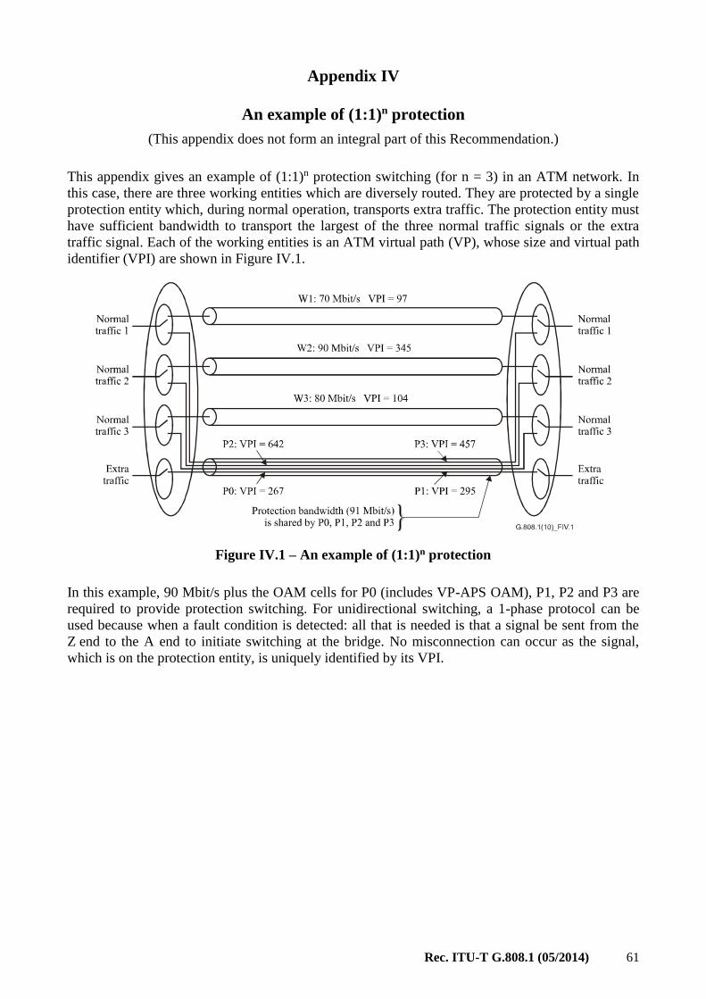
Rec. ITU-T G.808.1 (05/2014) 61
Appendix IV
An example of (1:1)n protection
(This appendix does not form an integral part of this Recommendation.)
This appendix gives an example of (1:1)n protection switching (for n = 3) in an ATM network. In
this case, there are three working entities which are diversely routed. They are protected by a single
protection entity which, during normal operation, transports extra traffic. The protection entity must
have sufficient bandwidth to transport the largest of the three normal traffic signals or the extra
traffic signal. Each of the working entities is an ATM virtual path (VP), whose size and virtual path
identifier (VPI) are shown in Figure IV.1.
Figure IV.1 – An example of (1:1)n protection
In this example, 90 Mbit/s plus the OAM cells for P0 (includes VP-APS OAM), P1, P2 and P3 are
required to provide protection switching. For unidirectional switching, a 1-phase protocol can be
used because when a fault condition is detected: all that is needed is that a signal be sent from the
Z end to the A end to initiate switching at the bridge. No misconnection can occur as the signal,
which is on the protection entity, is uniquely identified by its VPI.

62 Rec. ITU-T G.808.1 (05/2014)
Appendix V
Examples of survivability of inverse multiplexed trails
(This appendix does not form an integral part of this Recommendation.)
V.1 Survivability offered by LCAS
Using the inverse multiplexing capability of VCAT + LCAS where Y = Y-Xv and Z = Y-Xc and
the IMG is equivalent to a virtual concatenation group (VCG), the following example is provided.
The AI is transported using a VCG with X members (VC_n_Xv, ODUk_Xv), distributed over N
routes, where:
• All members belonging to the VCG have the same bandwidth.
• The bandwidth of the VCG is proportional to the number of active members.
• N = number of routes (1 ≤ N ≤ X) each containing one or more network connections within
the VCG.
• X = number of members in the VCG required to transport the client's bandwidth AI +
extra/protection capacity Z (X ≥ 1, Z ≥ 0).
• XACT = actual transported payload (0 ≤ XACT ≤ X); due to failure of one or more of the trails
the bandwidth of one or more members in the VCG will not be used to transport the AI.
For the transport of a 10 Mbit/s signal a VC-12-5v is required. Five individual VC-12 trails are set
up in this VCG, two are routed via route 1 and three VC-12 are routed via route 2 (Figure V.1). In
this particular case, the survivable bandwidth is 2 × VC-12, or 40 per cent, and the non-survivable
bandwidth is 3 × VC-12, or 60 per cent. When one extra VC-12 would have been provisioned
(E = 1) routed via route 1, the survivable bandwidth would have been 3 × VC-12 or 60 per cent and
the unprotected bandwidth 2 × VC-12 or 40 per cent.
Figure V.1 – Example LCAS survivability for 10 Mbit/s
signal over VC-12-(X + E)v (X = 5, E = 0, 1)

Rec. ITU-T G.808.1 (05/2014) 63
Appendix VI
Solution for SD triggered protection in PTN
(This appendix does not form an integral part of this Recommendation.)
NOTE 1 – The special SD behaviour described in this appendix is only required for the case of protection
switching in PTNs.
The detection of SD (e.g., packet loss) is based on service packets. In 1+1 protection normal traffic
is sent permanently on both working and protection entities. Therefore, the detection of SD and the
clearing of SD on both working and protection entities can be based only on the characteristics of
the original traffic.
However, in PTN with 1:1, 1:n, m:n and (1:1)n protection , there may be no end-to-end traffic on the
standby transport entity, which makes the detection of SD based on LM impossible and
consequently protection switch flapping may happen if no special measures are taken.
For this solution the detection of SD-W and SD-P is required and is used to prevent flapping.
Broadcast bridge for SD detection in SD-triggered protection
In the normal state, the normal traffic signal is bridged at the source only on the working transport
entity and only the SD condition of the working transport entity can be evaluated. When SD is
detected on the working transport entity, the sink end sends a SD-W indication to the source end,
and the selector at the sink end switches to the protection transport entity. The bridge at the source
end will then broadcast the normal traffic signal on both working and protection transport entities
and the performance of both working and protection transport entities can be monitored. If SD is
detected on the protection transport entity as well, i.e., SD-W and SD-P exist simultaneously, the
sink end will remain selecting the normal traffic signal from the protection transport entity to avoid
flapping between protection and working states.
The priority of SD-W and SD-P in the APS protocol is fixed as SD-W > SD-P to avoid flapping
between protection and working states.
NOTE 2 – The SD-W based protection switch action described above is performed under the assumption that
an SD condition on a transport entity is a rare condition, and it is thus unlikely that SD on the standby entity
will co-exist with SD on the active entity.

64 Rec. ITU-T G.808.1 (05/2014)
Appendix VII
Solution for service protection in DBN
(This appendix does not form an integral part of this Recommendation.)
NOTE – This is a special implementation proposed for service protection switching in dynamic bandwidth
networks (DBN). In this appendix, bandwidth degradation could trigger an SD condition or a bandwidth
degradation message.
For networks using links that offer dynamic bandwidth adjustment, additional consideration can be
made for protection action during bandwidth degradation periods. Under bandwidth degradation
conditions, where the available link bandwidth is less than that available under normal conditions,
some of the services associated with that particular link could potentially be no longer supported.
The solution presented here supports load sharing in DBNs and can provide protection for high
priority services while maintaining high network utilization.
G.808.1(14)_FVII.1
Link XY
Link XY
NE X
NE X
NE Y
NE Y
NE Z
NE Z
NE A
NE A
Service A
Service A
Service B
Service B
Service A
Service A
Service B
Service B
Connectiontermination point
Protectionswitching function
Active trail
Standby trail
Figure VII.1 – Load sharing in a dynamic bandwidth network
Figure VII.1 shows the concept of redistributing services through protection switching. In this
simple set-up a bandwidth change of link XY may trigger protection switching to redistribute the
services according to the current bandwidth. This is achieved through signalling the state of the
trail(s) on link XY to the head-ends. The state could be conveyed to the head-ends either as an SD
condition or a bandwidth degradation message.
Below is a generic linear protection example showing how this scheme may be deployed when
using a dynamic bandwidth link. In this example two trails supporting service A and service B share
the physical dynamic bandwidth link XY.

Rec. ITU-T G.808.1 (05/2014) 65
G.808.1(14)_FVII.2
Protected domain
Service A
Service B
Service A
Service B
Link XY
NE X NE Y
Network layer trailtermination point
Connectiontermination point
Protectionswitching functionE
E
E
E
E
E
E
EE
Figure VII.2 – Generic concept of trail protection over dynamic bandwidth links
In Figure VII.2, the NEs X and Y implement a dynamic bandwidth link XY. The bandwidth of the
link is dynamic in the sense that the NEs adjust the transmission rate in real time to current
propagation conditions. The transmission rate is increased during favourable conditions and
decreased at less favourable conditions. This adaptive functionality is implemented in the physical
layer (layer 1) and changes in the rate occur. From this follows that the NEs have access to the
current dynamic bandwidth for link XY, however, how this information is generated is not covered
by this appendix.
The services in Figure VII.2, service A and service B, are associated with service-specific
committed information rates (CIRs), CIR A and CIR B.
In the case where NE X and NE Y have the knowledge of service bandwidths, CIR A and CIR B,
signal degradation can be used for triggering protection switching. The generation of a SD for a trail
due to bandwidth degradation may then be implemented as follows:
During normal conditions, where the aggregated CIR for the trails (CIR A+ CIR B) is less
than the current link bandwidth, no trail is signalled as degraded as the trails/services
requirements have been met.
In the case where a current link bandwidth is being degraded to the extent that only the
most prioritized trail/service can be sustained, the less prioritized service is signalled as
degraded, as the requirement of that service cannot be met i.e., the service cannot be
sustained during the degradation.
In the case that the current bandwidth degrades to the extent that the CIR of the most
prioritized service cannot be met both services may be signalled as degraded.
The NEs (X and Y) which implement the connection termination point will raise the SD condition
for unsupportable/unsustainable trails. This condition is passed to the protection switching function
which may take protection switching action (if the trail is the working trail and there is a protection
trail available). The rationale for using SD (as opposed to SF) is that it may be interpreted as an
indication that service degradation is most likely to occur if using an SD conditioned trail. The
actual outcome however, depends on the total level of utilization of the bandwidth degraded link.
For those cases when all trails of a protection switching function have an SD condition it is still
viable to send the service over one of the trails as some bandwidth may still be available.
66 Rec. ITU-T G.808.1 (05/2014)
Furthermore, it is assumed that alarm and fault handling is improved if link failure and bandwidth
degradation can be separated.
In the case where NE X and NE Y have no knowledge of the service bandwidth, a bandwidth
degradation message can be used for triggering protection switching. This method can be applied in
the ACL-SNCG/I protection switching scheme. Protection switching can be performed as follows:
During normal conditions, no bandwidth degradation message is sent by NEs (X and Y).
In the case of link bandwidth degradation, bandwidth degradation messages which carry
current bandwidth information are signalled to the head-ends. This bandwidth information
is the current bandwidth allocated for the component link on link XY.
The head-end may update the distribution policy based on the received bandwidth
information. In the case that multiple degradations occur along one component link, the
head-end may receive multiple and different bandwidth values. The lowest value should be
selected.
The head-end will perform protection switching to redistribution services on the component
links according to the updated distribution policy.

Printed in Switzerland Geneva, 2014
SERIES OF ITU-T RECOMMENDATIONS
Series A Organization of the work of ITU-T
Series D General tariff principles
Series E Overall network operation, telephone service, service operation and human factors
Series F Non-telephone telecommunication services
Series G Transmission systems and media, digital systems and networks
Series H Audiovisual and multimedia systems
Series I Integrated services digital network
Series J Cable networks and transmission of television, sound programme and other multimedia signals
Series K Protection against interference
Series L Construction, installation and protection of cables and other elements of outside plant
Series M Telecommunication management, including TMN and network maintenance
Series N Maintenance: international sound programme and television transmission circuits
Series O Specifications of measuring equipment
Series P Terminals and subjective and objective assessment methods
Series Q Switching and signalling
Series R Telegraph transmission
Series S Telegraph services terminal equipment
Series T Terminals for telematic services
Series U Telegraph switching
Series V Data communication over the telephone network
Series X Data networks, open system communications and security
Series Y Global information infrastructure, Internet protocol aspects and next-generation networks
Series Z Languages and general software aspects for telecommunication systems