iTrain 2 manuali-train.nl/download/2-1/iTrain 2 manual.pdfsave them in the folder iTrain/layouts in...
147
Version: 2.1 Author: Xander Berkhout © 2012 Berros. All rights reserved. Manual Version + year
Transcript of iTrain 2 manuali-train.nl/download/2-1/iTrain 2 manual.pdfsave them in the folder iTrain/layouts in...

Version: 2.1Author: Xander Berkhout© 2012 Berros. All rights reserved.
Manual
Version + year
ContentsPreface ! 8
Introduction! 9The main window! 9Main objects! 9Naming! 10File handling! 10
Backup! 11Zip files! 11Recent files! 11Import! 11
Online! 12License! 12Project! 13
Preferences! 14General! 14
Language! 14Length unit! 14
Switchboard! 15Interface! 15
Grouping! 16
Network! 17Remote Control! 17
Settings! 18Track! 18Speed! 18
Interface ! 20Multiple interfaces! 21General! 22
Accessory! 22Feedback! 22
Serial interface! 23Specific! 25Status! 25

Locomotives ! 27Create or edit a loc! 27Definition! 28
Inertia simulation! 31Polarity! 31Reaction delay! 31Detection! 31
Loc control! 32Loc grid! 34
Loc overview! 35Traction or consist! 36Calibrate loc speed! 37
Switchboard! 40Zoom! 40Quality! 40Overview! 41Layout View! 41Controlling Switches! 42Create or edit the switchboard! 44
Toolbar! 46Layers ! 48Browser! 49Template! 50
Assign control objects! 50Key mappings! 51
Accessories! 52Output Device! 53Cross turnouts! 54Turnout state feedback! 55Warning signals! 55Options! 56Turnout options ! 56
Feedbacks! 57Track routes! 58Blocks! 61
Feedback! 64Shift! 65
Signal! 66Block! 66

Connections! 67Positions! 69Options! 71
Speed! 72Block control! 73Relay! 73
Feedback positions! 74
Stations! 75Turntable! 76
Decoder! 77Accessory! 78Feedback! 79Block! 80Control! 80
Transfer table! 81Accessory! 81Feedback! 82Block! 83Control! 83
Deleting switchboard elements! 84Reusing control objects! 84Adding/Modifying switchboard tabs! 84
Trains! 85Create or edit a train! 85
Options! 85Permissions! 86
Use a train! 86
Reservations! 87Release blocks! 88Removing locs from blocks! 88Moving locs over or into the switchboard! 88Context popup menu! 89
Routes ! 90Waiting time! 91Markers! 91Critical block! 91Blocks! 91Functions! 93

Options! 94Route control! 95
Info! 96Scheduled stop! 96
Instant route! 96
Editors! 98Accessories! 99Blocks/Stations! 99
Extra tools ! 100Keyboard! 100Feedback Monitor! 101
S88 Address numbering! 101
Extra! 102
Network! 103Server mode! 103Client mode! 104iOS! 105Status! 105
Appendix A: Defined keys! 106Globally defined keys! 106Loc keys! 107Switchboard control keys! 109Switchboard edit keys! 110All tool windows! 112
Appendix B: Feedbacks ! 113Occupancy! 113Momentary! 113
Appendix C: iTrain user forum! 114
Appendix D: Interface specifics ! 116Demo! 116Märklin 6051! 116P50X! 117
TAMS Master Control! 117

OpenDCC (P50X)! 117Raptor! 118MRdirect! 118Twin Center! 118Intellibox (P50X)! 118
LocoNet®! 119Intellibox USB (LocoNet®)! 119LocoNet®! 119LocoNet® TCP/IP! 120LocoNet® Multicast! 120
ESU! 121ECoS ESU! 121Märklin Central Station 1! 121
Märklin Central Station 2! 123XpressNet! 125
Lenz XpressNet/X-Bus (Serial / USB / IP)! 125S88 XpressNet LI! 126MoBaSbS! 127Rocomotion! 127Hornby! 128
Selectrix! 129Selectrix! 129Rautenhaus SLX! 129Rautenhaus RMX! 130Müt 2004! 131FCC (Doehler & Haass / MTTM)! 131Stärz ZS1! 132Stärz ZS2! 132
Zimo! 134Massoth! 135VPEB / DinaSys! 136
Dinamo! 136OM32! 137OC32! 138PM32/OM32! 138DTC! 138
Littfinski Daten Technik (LDT)! 140Digital-S-Inside 2 / DiCoStation! 140HSI-S88! 140HSI-S88 USB! 141
Lokstore Digital! 142µCon-S88-Master! 142

µCON-Manager! 142
CAN-digital-Bahn! 144CAN-Control-Schnitte! 144CAN-PC-Schnitte! 145
RailCom! 146TAMS RailCom Link! 146
Games on Track! 147Games on Track GT-position! 147

PrefaceAfter many years of development iTrain reached version 2.1 that works on operating systems used mostly today. The user interface and the manual are available in some of the worldʼs major languages. This combination of operating system and language support makes the program available to a wide audience. It would cost too much time to create manuals and to keep them up to date for all operating systems beside all the translations. The differences between the operating systems in using iTrain are limited. This manual is written with the Mac OS X user in mind so all screenshots are made on this platform and the key commands described are targeted on this platform. For Windows and Linux users the screen layout and dialogs will be more or less the same, but with other colors and styles that are common for their environment. The most important difference between the operating systems is the use of the modifier keys. The ʻCommandʼ key on the Mac is not available on other systems and should be replaced by the ʻControlʼ key. The ʻOptionʼ key on the Mac is also called ʻAltʼ and in this manual we use this term, because it is the same on all platforms.Popup menus or context sensitive menus can normally be accessed by clicking the right mouse button while the mouse is above a specific object. In addition Mac OS X also allows you to get a popup menu by holding the ʻControlʻ key and pressing the left or the single mouse button.This manual introduces all the important aspects that you need to know to use iTrain. However, it doesnʼt explain general concepts of digital model railroads in much detail, so knowledge of this is a prerequisite. This has been done to keep the manual compact and readable. I recommend reading all chapters in order and at the same time run iTrain with the demo layout (demo.tcd in the folder iTrain/layouts).There is a dedicated forum available (http://berros.eu/itrain/forum/) for iTrain users. It contains answers to questions you might have and if your question is not there you can ask your own. By using the forum, instead of e-mail or phone, questions can be answered to a broader audience. A lot of enthusiastic iTrain users, including me, are active on the forum helping each other. See Appendix C for more information about the forum.
Kind regards,
Xander Berkhout
iTrain 2 - manual
8 of 147
Why only a Mac manual
Describe differences better
Folder added
New Forum/support

IntroductionWhen you start working with iTrain for the first time you will need to know some basic concepts of the program.
The main windowAn ordinary screen in iTrain may look like the following (see the demo.tcd file):
In this screen we can identify three main areas:1. The loc overview in the upper left corner gives an overview of the status of every loc
and gives immediate control over the main functions of a loc. 2. The loc control or throttle in the lower left corner gives more control over all the settings
of a loc and is meant to control one loc in detail.3. The switchboard on the right side is a simplified drawing of your layout, in which you
see where your trains are and what the state of all turnouts, signals and other objects is. You can also change the state of all objects.
Main objectsIn iTrain we distinguish several types of objects:• Locomotive (also called loc) - refers to the actual loc that you can control.• Train - refers to all the wagon combinations that can be pulled or pushed by a loc.• Accessory - switchable objects
• Turnout - is the switch to join multiple tracks in one or split one track into multiple tracks.
• Signal - may refer to actual signals on the layout or only virtual signals on the switchboard to indicate if a train should stop or is allowed to drive (optionally with restricted speed).
• Decoupler - to decouple a loc from a train or to split a train into two trains.
iTrain 2 - manual
9 of 147

• Relay - is a switch with an on/off state (for example light) or a two state.• Turntable - a circular device with track connections on the side and a bridge in the
middle so that a loc can drive unto the bridge and be turned to exit at any direction.• Transfer table or traverser - a rectangular device with track connections on two sides
and a bridge in the middle that can move sideways to connect with the tracks on one side or two opposite sides.
• Feedback - refers to sensors in the track that detect if part of a track is occupied or not (see Appendix B).
• Block - is a part of a track (not including turnouts) where only one train and its locs is allowed to be in.
• (Train) Route - is the route or path a train and its locs can follow when driving automatically from block to block.
• Station - is a list of blocks grouped together so they can be used as a destination in a route without specifying all the blocks individually.
• Track Route - is a list of turnout (and other accessory) settings that create a path, for example from one block to a neighboring block, like in the Märklin Memory module.
NamingIn iTrain all locs, turnouts, signals and all other objects have a name that is unique per object type. You donʼt have to remember all the addresses, because you can give every object a useful name. It is recommended to keep the names short and use a naming convention that you understand. Every object can also have a description to give a more descriptive name to your own wishes, but it may be left empty.For example, for the name of a loc you can use the operator name like NS, DB or SBB followed by a space and the number of the loc, for example DB 101. If you have multiple locs of the same type, use a different suffix, for example DB 101-2 or the road number DB 101-104-8.For the names of blocks and accessories you can use logical numbers prefixed by an identification of the station and separated by underscores. You could name the two sides of a block A and B to distinguish feedbacks and signals on the side. For example, CS_S4A is the Signal of the Central Station of track/block 4 on the A-side. All references to this signal in the definition of your layout will show this name. It is difficult to name turnouts, because they are the connection between blocks. You could prefix them with station and just number them in order, like CS_W5. Note:! It is recommended to name your objects independently of the actual address of the
object and choose a more logical name based on the location in the layout. Using the address in the name violates this principle. The address will be displayed between parentheses behind the name in many cases you might need it (such as with selection boxes).
File handlingAfter you have started iTrain for the first time, no file has been associated with your project so you have to save your project with a specific name. It is recommended to use the extension .tcd for iTrain files (tcd =Train Control Data), for example layout.tcd, and to save them in the folder iTrain/layouts in your home directory and not in the folder
iTrain 2 - manual
10 of 147
Folder
A en B side
Name and address separation
Names of turnouts

Applications (or Program Files for Windows). On Mac OS X this folder will not be created by the installer so you have to create it manually once.Note:! On OS X the .tcd files will get a special icon to indicate that it is an iTrain
file and you can double-click it to open the file.The next time you start the program, it will automatically try to load the same project. The project name will be shown in the title bar of the main window (together with the full path to the file and the iTrain version in which it was created). When closing the program the project will be saved automatically, unless you have chosen to do that manually. This will not only save the definitions of all objects, but also the current state of the layout (where are the locs and what was the last state of all accessories).BackupBefore saving a file, the previous file (with the same name) will be moved to a backup subdirectory and the date and time will be added to the file name. This way you always have a backup of the previous states of your layout in case something goes wrong. The name of the backup files have the following format that includes the original name followed by the word backup, the date and time of creation of the backup and the version of iTrain with which it has been saved.
layout_backup-20120719-151902_v2.1.0.tcd
To restore a backup just open the file from the backup subdirectory in iTrain and the original file name and path will be restored. So it is not necessary to copy and rename files from the backup directory. The backup directory may fill up fast with every save, but the files are in general small compared to the available disk space. You could clean them up if you want, but in general it is not necessary.Zip filesYou can store your project as a compressed file in the .zip format by adding the extension .zip to the end of the filename. So if you choose the filename layout.tcd.zip an archive will be created with the file layout.tcd in it. If a file is opened with an extension .zip it will try to open the archive and find a file with the extension .tcd in it or if it contains only a single file it will open that. In case the archive was not created by iTrain, the title bar will show the file that was chosen within the archive behind the filename between braces.
/Users/berros/iTrain/layouts/examples.zip:{garden.tcd}
Note:! Working with zip files saves disk space, because the files will be much smaller (more than 10 times smaller is possible). This also makes the disk space used by backups much smaller, because these files will be compressed now as well.
Tip:! It is not allowed to attach .tcd files directly to the forum when exchanging your layouts, but you have to zip them first manually. By saving them already as zip-files this step is not necessary anymore.
Recent filesThe menu item ʻOpen recent filesʼ shows a list of up to 10 files that have been opened recently. You can go back to an earlier opened file quickly by selecting it from the list, but do save the current file first if you have made modifications that you want to store.ImportThe import allows you to open a file as well. But it will import only a certain part of it: locomotives and trains. The import will add this part to your already loaded file. The import dialog contains two tabs, showing all the locomotives and trains which can be imported.
iTrain 2 - manual
11 of 147
New Zip files support
New Import
New Recent files
New Extra icon for .tcd files
Format of backup file
Full path
Restore backups.

You can now select the objects you want to import and also indicate whether they should be imported actively or inactively. Possible conflicts with existing objects are displayed in the last column.
OnlineWhen you are working with the program sometimes you only want to change your configuration and at other times you are really controlling the trains on your layout. In the second case you will need a connection to the control device and when this is done the program is ʻonlineʼ. In the right lower corner of the screen you can see whether you are ʻOnlineʼ or ʻOfflineʼ. This is the current status. With the button on the toolbar you can change the status to ʻOnlineʼ (text below button is ʻConnectʼ) or ʻOfflineʼ (text below button is ʻDisconnectʼ).Note:! It is always recommended to select ʻDisconnectʼ or exit iTrain before turning off your
control device so that it can disconnect correctly. If you accidentally turn it off before going offline then check if the program did detect it or else do it manually instead.
LicenseiTrain is a commercial product and runs by default in demo mode. You are limited to 3 locomotives and 32 accessories and 32 feedbacks. This allows you to test iTrain on a small demo layout like the one supplied (demo.tcd).To make use of all features available in iTrain you have to register and you will get a license that is coupled with your e-mail address. To enter your license number go to main menu ʻOptionsʼ -> ʻEnter license keyʼ.
Type or copy your e-mail address that you used to get a license and paste your license key into the ʻLicense Keyʼ box by using Command key + V or the popup menu. It is not recommended to manually type it.
iTrain 2 - manual
12 of 147
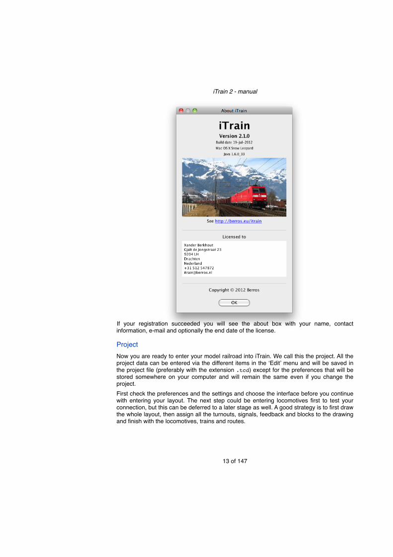
If your registration succeeded you will see the about box with your name, contact information, e-mail and optionally the end date of the license.
ProjectNow you are ready to enter your model railroad into iTrain. We call this the project. All the project data can be entered via the different items in the ʻEditʼ menu and will be saved in the project file (preferably with the extension .tcd) except for the preferences that will be stored somewhere on your computer and will remain the same even if you change the project.First check the preferences and the settings and choose the interface before you continue with entering your layout. The next step could be entering locomotives first to test your connection, but this can be deferred to a later stage as well. A good strategy is to first draw the whole layout, then assign all the turnouts, signals, feedback and blocks to the drawing and finish with the locomotives, trains and routes.
iTrain 2 - manual
13 of 147

PreferencesThe preferences are settings that apply to all projects and are saved on the computer itself in an application specific location. You can find them in the iTrain menu on Mac OS X or at the bottom of the ʻEditʼ menu on other operating systems.
GeneralIn the ʻGeneralʼ tab you can change some specific settings of the behavior of iTrain. It is possible to save the project when closing iTrain without asking for confirmation. By default a check is done if a newer version of iTrain is available at startup. If your computer is never connected to a network you can turn this off.
LanguageThe iTrain user interface is available in multiple languages. By default it will choose the same language as the operating system and this is called ʻSystem Defaultʼ, but you can change it to a language you prefer. The changes will not be active directly, but only after restarting iTrain, because the user interface has to be reloaded.Length unitThe length unit specifies what kind of measure is used throughout iTrain for displaying length. It is recommended to use centimeters, because that will fit naturally with the scale of most models and is also used internally. Millimeters, meters, inches and feet are also selectable options. Length values are floating point values so you can have 51.5 cm or 0.515 m. In every length input box in the program you can always enter a value in another unit by adding the unit to the value. It is automatically converted to the unit specified in this preference after hitting the ENTER key. The possible suffixes for length units are ʻmmʼ, ʻcmʼ, ʻdmʼ, ʻmʼ, ʻinʼ and ʻftʼ. When you do not specify a unit in a length input box, the default specified in the preferences is assumed.Speed unitThe speed unit specifies what kind of measure is used for displaying speed corrected for scale throughout the application. The natural unit would be km/h or mph, but also m/s is possible. Speed unit values are also floating point values. In every speed input box in the program you can always enter a value in another unit by adding the unit to the value. It is
iTrain 2 - manual
14 of 147
Extra language option

automatically converted to the unit specified in this preference after hitting the ENTER key. The possible suffixes for speed units are ʻcm/sʼ, ʻm/sʼ, ʻkm/hʼ and ʻmphʼ.
SwitchboardThe ʻSwitchboardʼ tab has some generic settings for the switchboard that apply to all projects. The option ʻDefault gridʼ decides if a new switchboard or the switchboards in a newly opened project will be shown with a grid. It will not affect current switchboards, because you configure it for the existing switchboard via the popup menu. To automatically use the maximum allowed zoom that does not need scrolling for newly opened projects, select ʻDefault fitʼ.
The look or appearance is a set of colors, line widths and text size used to draw the layout. There are three looks available:• Default - a white background and drawn as in all previous versions• Contrast - with a light gray background that is easier for the eyes and makes the colors
better identifiable, somewhat bigger font for better readability• Dark - using a dark background and lighter track lines so colors of feedbacks and signals
have better contrast
InterfaceOn the ʻInterfaceʼ tab you find some interface related preferences. By default iTrain starts ʻOfflineʼ and you have to go ʻOnlineʼ manually, but you can choose to try to connect directly when starting iTrain when the computer is always connected to the layout and turned on before iTrain is started.
iTrain 2 - manual
15 of 147
New switchboard preference
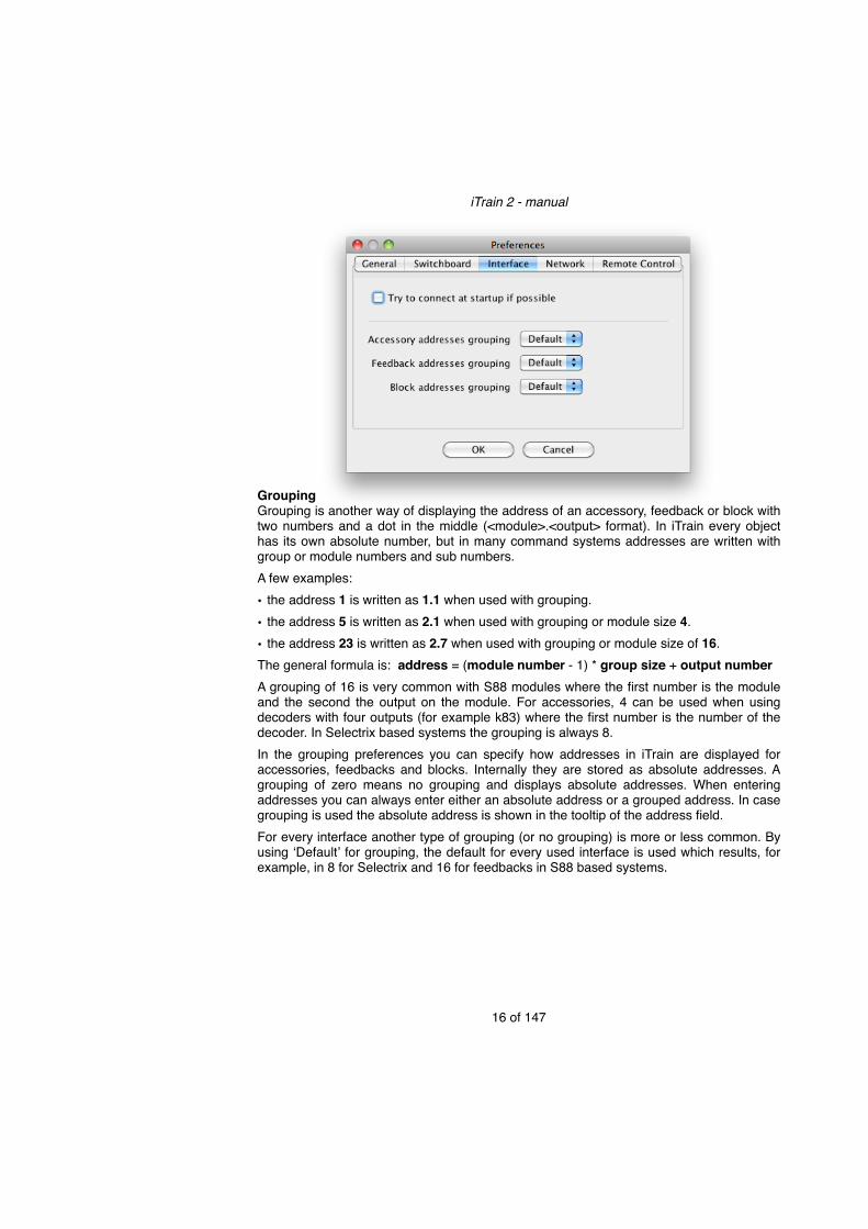
GroupingGrouping is another way of displaying the address of an accessory, feedback or block with two numbers and a dot in the middle (<module>.<output> format). In iTrain every object has its own absolute number, but in many command systems addresses are written with group or module numbers and sub numbers.A few examples:• the address 1 is written as 1.1 when used with grouping.• the address 5 is written as 2.1 when used with grouping or module size 4.• the address 23 is written as 2.7 when used with grouping or module size of 16.The general formula is: address = (module number - 1) * group size + output numberA grouping of 16 is very common with S88 modules where the first number is the module and the second the output on the module. For accessories, 4 can be used when using decoders with four outputs (for example k83) where the first number is the number of the decoder. In Selectrix based systems the grouping is always 8.In the grouping preferences you can specify how addresses in iTrain are displayed for accessories, feedbacks and blocks. Internally they are stored as absolute addresses. A grouping of zero means no grouping and displays absolute addresses. When entering addresses you can always enter either an absolute address or a grouped address. In case grouping is used the absolute address is shown in the tooltip of the address field.For every interface another type of grouping (or no grouping) is more or less common. By using ʻDefaultʼ for grouping, the default for every used interface is used which results, for example, in 8 for Selectrix and 16 for feedbacks in S88 based systems.
iTrain 2 - manual
16 of 147
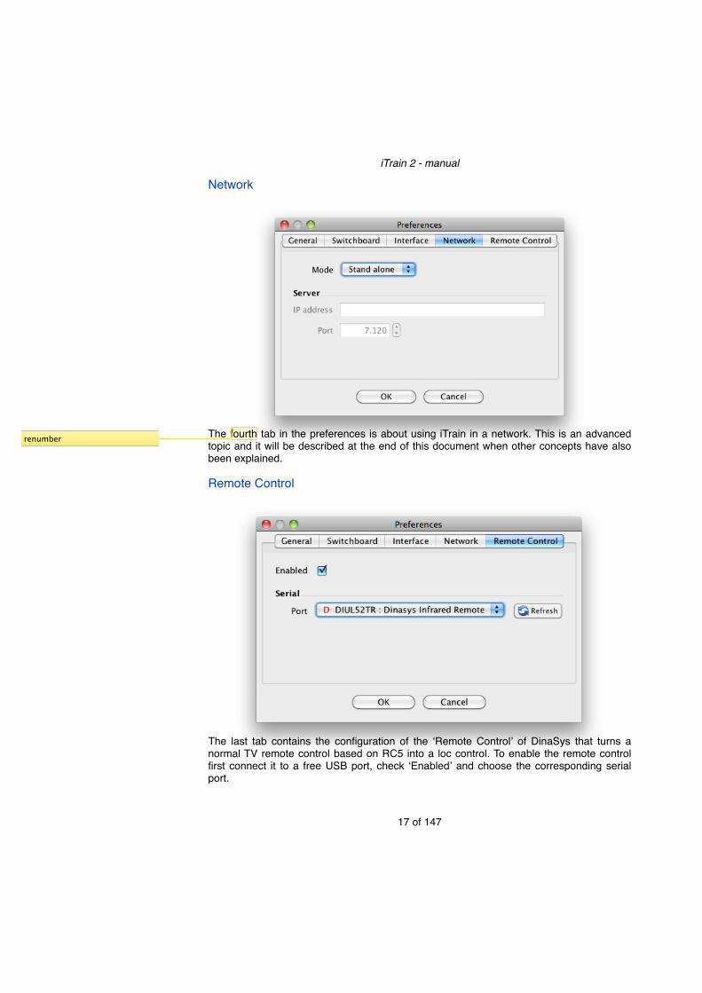
Network
The fourth tab in the preferences is about using iTrain in a network. This is an advanced topic and it will be described at the end of this document when other concepts have also been explained.
Remote Control
The last tab contains the configuration of the ʻRemote Controlʼ of DinaSys that turns a normal TV remote control based on RC5 into a loc control. To enable the remote control first connect it to a free USB port, check ʻEnabledʼ and choose the corresponding serial port.
iTrain 2 - manual
17 of 147
renumber
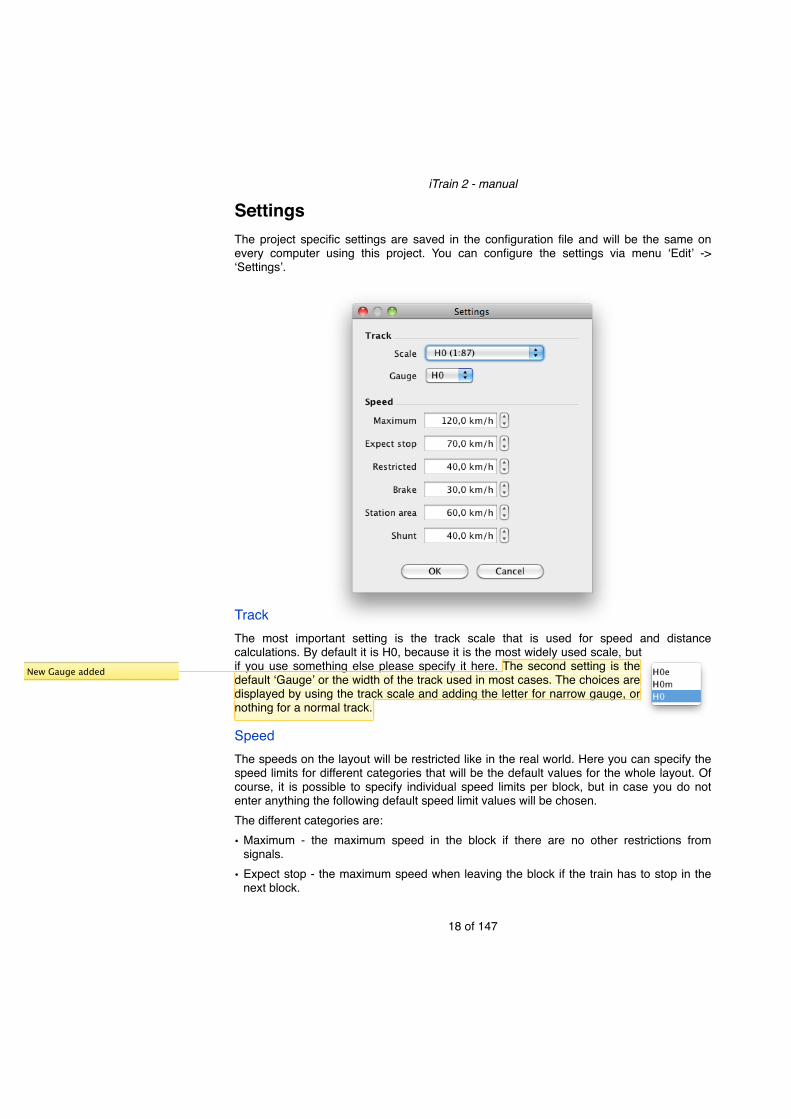
SettingsThe project specific settings are saved in the configuration file and will be the same on every computer using this project. You can configure the settings via menu ʻEditʼ -> ʻSettingsʼ.
TrackThe most important setting is the track scale that is used for speed and distance calculations. By default it is H0, because it is the most widely used scale, but if you use something else please specify it here. The second setting is the default ʻGaugeʼ or the width of the track used in most cases. The choices are displayed by using the track scale and adding the letter for narrow gauge, or nothing for a normal track.
SpeedThe speeds on the layout will be restricted like in the real world. Here you can specify the speed limits for different categories that will be the default values for the whole layout. Of course, it is possible to specify individual speed limits per block, but in case you do not enter anything the following default speed limit values will be chosen.The different categories are:• Maximum - the maximum speed in the block if there are no other restrictions from
signals.• Expect stop - the maximum speed when leaving the block if the train has to stop in the
next block.
iTrain 2 - manual
18 of 147
New Gauge added

• Restricted - the maximum speed if the signal shows the restricted sign, for example when a turnout is branched in the path to the next block.
• Brake - the speed to which a train brakes in case of a red signal until it enters the stop feedback.
• Station area - the maximum speed for blocks of type ʻStationʼ or ʻShuntʼ1.• Shunt - the maximum speed for blocks of type ʻSidingʼ, ʻTurntableʼ or ʻTransfer tableʼ.
iTrain 2 - manual
19 of 147
1 Blocks of type ʻShuntʼ are part of the station area and will be passed by normal trains as well.

InterfaceThe program normally communicates via a serial, USB or ethernet cable with a command station directly or via a separate device that is connected to the command station. The device connected to the computer is called ʻInterfaceʼ and several types of interfaces from different suppliers are supported. Every interface has limitations in the type of decoders supported and the number of loc speed steps and functions allowed. Therefore it is necessary to first select the interface before continuing with other definitions.
Via the menu ʻEditʼ -> ʻInterfaceʼ you can select the ʻInterfaceʼ that is connected to your computer. The ʻDescriptionʼ field allows you to change the description of the interface in the application. If left empty, the description in the ʻInterfaceʼ field will be used. On the tab at the bottom you can see how the interface will be displayed with the number of the interface in front of it.By default an interface will control the locomotives, accessories and read the feedbacks in iTrain, but it is also possible to restrict the control of the interface by changing the checks for ʻControl typeʼ. This is mainly used when using multiple interfaces at the same time (see later on). Some interfaces are only made to control accessories and/or read feedbacks. In that case some ʻControl typesʼ will be invisible.The more specific interface settings are divided over multiple tabs on top called ʻGeneralʼ, ʻSerialʼ, ʻNetworkʼ and ʻSpecificʼ.
iTrain 2 - manual
20 of 147
invisible instead of disabled

Multiple interfaces2
iTrain has been designed to work with multiple interfaces at the same time. This is why you see the ʻ1ʼ in front of the interface on the tab at the bottom.
To add another interface you need to use the popup menu on this tab and select ʻAddʼ. This will add an extra tab with the label starting with a ʻ2ʼ in which you can configure the second interface. You can also remove an interface via the popup menu, but only the one added last (with the highest number) can be removed.Note:! If the popup menu is not available then your license does not allow multiple
interfaces. In this case, you can always upgrade your license to ʻProfessionalʼ via the website.
There are several cases in which multiple interfaces can be useful. A few are listed below, they may be combined if required:• You want to read the feedbacks in via a separate device to get better results. In that case
you can use an HSI-S88 as a second interface and disable the ʻFeedbacksʼ in your first interface.
• You want to control signals via a separate device (OM32 or OC32) that directly controls the lights bulbs.
iTrain 2 - manual
21 of 147
2 This option is only available in the Professional edition of iTrain.

• You want to switch all your accessories via an old command station so that you have all the power of your new command station for running your locs.
• You are controlling two layouts or two different systems (for example 2-rail and 3-rail) at the same time and you want to manage them all in one application.
Tip:! In case you use the same type of command station twice, but each with another role, you can use the description to distinguish them.
GeneralOn the ̒ Generalʼ tab you can set some properties that involve almost all interfaces and are about accessories and feedbacks.
AccessoryThe default accessory protocol is the protocol used by default when creating an accessory. In case your command station also supports a default value for accessory protocols (for example the ECoS), it should be set identical.The ʻActivation timeʼ is the default time between the activation of an accessory and its release. This can be overridden per accessory. Not every interface supports this default ʻSwitch delayʼ, but in case the interface will not use it then it is also the time iTrain will wait until the next accessory is activated. This prevents overloading of the input buffer of the command station.By default all accessories are activated when going ʻOnlineʼ so that the state on your layout and in iTrain will be identical. This takes some time and you can switch it off if you are sure that you did not change accessories manually or with the control device when iTrain was not running. If you switch this option off, iTrain will try to read the state from the command station if the interface supports this.FeedbackFeedbacks are the eyes of the program and it is important that they deliver good results. In some cases it is necessary to filter the raw input to remove short spikes, because of bad contact between the wheels and the track. Some higher priced feedbacks modules have this filtering built-in. In this case it is recommended to use the hardware filtering, because it does not cost processing time and is probably more accurate. If it is not available you can use the software filtering.
iTrain 2 - manual
22 of 147
feedbacks added
New Feedback filtering
The ʻSwitch on delayʼ is the time a feedback needs to be on before the feedback sees it as on. The same holds for ʻSwitch off delayʼ, so an off is only seen as off after some time without an on. In general it is important to keep the ʻSwitch on delayʼ short, because most actions are based on a feedback going on and it might delay the action. In most cases you can leave it to zero, but if you use it then use a small value (< 50 ms).The ʻSwitch off delayʼ is less critical because a feedback going off is mostly used to notify that a a block is not occupied anymore. Short contact loss should not result in a feedback going off, so a short delay is preferred to an unwanted release. Common values for ʻSwitch offʼ are in the range 100-500 ms.This feedback filtering is the default setting for all feedbacks attached to this interface. It can be overridden for any individual feedback. This is useful if you combine feedback modules with different characteristics.Note:! Filtering the feedback output also results in fewer transitions from on to off and back
again and will improve the overall performance of the application, because actions and checks will not be executed unnecessarily.
Depending on the interface the Serial or Network tab will be enabled to configure.
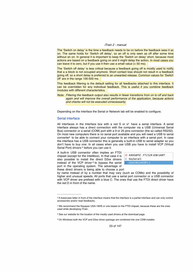
Serial interfaceAll interfaces in the Interface box with a red S or s3 have a serial interface. A serial interface always has a direct connection with the computer via a USB (Universal Serial Bus) connector or a serial (COM) port with a 9 or 25 pins connector (the so called RS232). On most new computers there is no serial port available and you will need a USB to serial converter4 to be able to connect your computer to an interface with a serial port. In case the interface has a USB connector this is generally a built-in USB to serial adapter so you donʼt have to buy one. In all cases when you use USB you have to install VCP (Virtual Serial Port) drivers 5 before you can use it.A built-in USB connector often implies an FTDI chipset (except for the Intellibox). In that case it is also possible to install the direct D2xx drivers instead of the VCP driver 6 to bypass the serial port in the operating system. The advantage of these direct drivers is being able to choose a port by name instead of by a number that may vary (such as COMx) and the possibility of higher and unusual speeds. All ports that use a serial port connector or a USB connector with VCP driver are prefixed with a blue C. The ones that use the FTDI direct driver have the red D in front of the name.
iTrain 2 - manual
23 of 147
3 A lowercase letter in front of the interface means that the interface is a partial interface and can only control accessories and/or read feedbacks.
4 We recommend the Keyspan USA-19HS or one based on the FTDI chipset, because these are the ones used while developing iTrain.
5 See our website for the location of the mostly used drivers at the download page.
6 On Windows both the VCP and D2xx driver package are combined into one CDM installer.
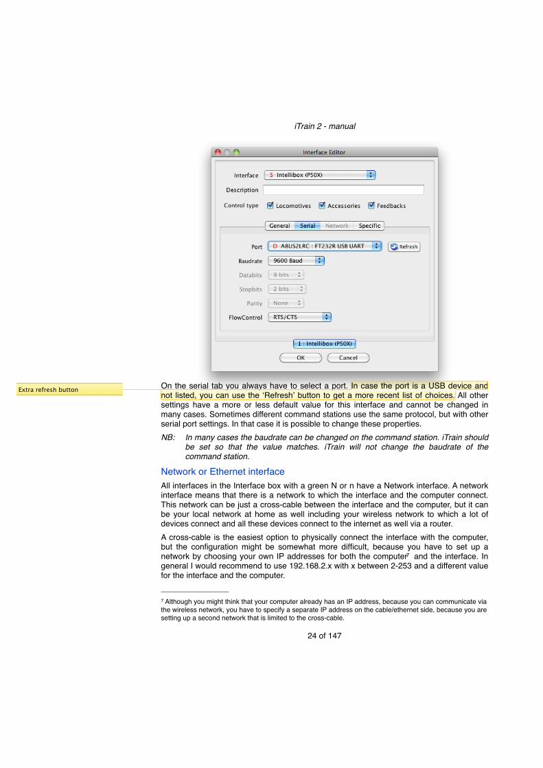
On the serial tab you always have to select a port. In case the port is a USB device and not listed, you can use the ʻRefreshʼ button to get a more recent list of choices. All other settings have a more or less default value for this interface and cannot be changed in many cases. Sometimes different command stations use the same protocol, but with other serial port settings. In that case it is possible to change these properties.NB:! In many cases the baudrate can be changed on the command station. iTrain should
be set so that the value matches. iTrain will not change the baudrate of the command station.
Network or Ethernet interfaceAll interfaces in the Interface box with a green N or n have a Network interface. A network interface means that there is a network to which the interface and the computer connect. This network can be just a cross-cable between the interface and the computer, but it can be your local network at home as well including your wireless network to which a lot of devices connect and all these devices connect to the internet as well via a router.A cross-cable is the easiest option to physically connect the interface with the computer, but the configuration might be somewhat more difficult, because you have to set up a network by choosing your own IP addresses for both the computer7 and the interface. In general I would recommend to use 192.168.2.x with x between 2-253 and a different value for the interface and the computer.
iTrain 2 - manual
24 of 147
7 Although you might think that your computer already has an IP address, because you can communicate via the wireless network, you have to specify a separate IP address on the cable/ethernet side, because you are setting up a second network that is limited to the cross-cable.
Extra refresh button

The other option is to connect the interface to your existing network so you donʼt have to set up your own network. In that case the interface will get an IP address automatically when using DHCP or you can choose one manually with the restriction that it should match the network number and have a unique host number (2-253 to prevent conflicts with routers). An advantage is that the interface is also connected to the internet for updates and other handheld devices can connect to it as well without changing cables.
The main thing that is needed by iTrain is the IP address or the host name8 of the interface. In most cases there is no need to change the default port number, because it is specific for the interface and set by default. The timeout is used while making the initial connection and to determine if the command station is still reacting. Values should be in the range from 250 to 5000 ms (0 means wait for ever and should not be used).
SpecificThe last tab called ʻSpecificʼ is for settings that are different for every interface. The list of supported interfaces has become very extensive and you probably need only one or two for your project. Therefore we refer you to the Appendix D for interface specific information.
StatusThe status of all interfaces is shown on right side of the status bar. It shows the name or description of the interface, if the individual interface is ʻOnlineʼ or ʻOfflineʼ and optionally the track power status. For some interfaces extra information like the voltage or current may be shown.
iTrain 2 - manual
25 of 147
8 When using DNS (for example via the router or a server) you can use a name instead of an IP address.
New reference to Appendix D

By hovering over name of the interface it will show a tooltip with extra information about the interface like the firmware version (if available) and possibly other properties. Between brackets the letters LAF or a subset indicate what the interface has been configured to control (L = Locomotives, A = Accessories, F = Feedbacks).
In some cases it will show an extra information icon in front of the name. This means more information is available by double-clicking on it, such as with the Central Station 2.
iTrain 2 - manual
26 of 147

LocomotivesThe locomotive or simply called loc is an important object in iTrain. Before you can do anything with your locs you will need to add them to iTrain. Tip:! Some interfaces will import your locs automatically (like the ECoS and Central
Station) when you go ʻOnline. In this case you can work immediately, but iTrain can store more information about your locs than these interfaces supply.
Create or edit a locTo get into to the ʻLocomotive editorʼ you go to the menu ʻEditʼ -> ʻLocomotivesʼ or press Command + F2.
At the left side is the list of the locs known by iTrain. This is typically your whole collection. In the ʻActiveʼ column you can indicate which locs are currently available on the layout so that elsewhere in the program where you have to select a loc only the active locs are shown. When in doubt just mark it active.To manage the list of locs you use the buttons below the list. You can add a new loc by using the ʻNewʼ or ʻCopy button. In case of ʻCopyʼ the currently selected loc is used as a template and its definitions are copied to the new loc. Only the name is adapted to create a unique name. The ʻDeleteʼ button removes the currently selected loc from the list. On the right side you find the loc editor to change all loc definitions. You have to fill in at least a name, decoder type and address to be able to use the loc. The buttons below the editor give some extra control over the editor:• The ʻApplyʼ button applies changes you made in the input fields. This will immediately be
reflected in all windows. If you select another loc the previously selected loc will automatically be applied.
• The ʻResetʼ button discards the changes you made in the editor and reloads the fields with the current value. After an ʻApplyʼ a reset will only discard changes made after the ʻApplyʼ.
iTrain 2 - manual
27 of 147

• The ʻClearʼ button clears all the fields.Tip:! This layout with on the left side a list and on the right side an editor and the same
buttons are used more often for other main objects in iTrain.
DefinitionThe ʻLoc typeʼ is important to specify correctly when using routes (explained later), because electric locs cannot run on tracks without a wire. The ʻLengthʼ of a loc is also useful to determine if a loc and train combination fit into a block (explained later).In the ʻDecoderʼ section you can specify the decoder ʻTypeʼ, the ʻInterfaceʼ and the ʻAddressʼ (for a loc without decoder you choose analog and no address). The ʻFunction addressʼ is used to switch functions via a second address if the decoder is limited in the number of allowed functions. This way it is possible to switch f0-f8 with a Motorola or MFX decoder on any system with Motorola support.The ʻMotorola MFX (28)ʼ choice is for MFX decoders used with a system that does not support or has disabled MFX (for example the ECoS) and uses the decoder with 28 steps.Tip:! When using the Central Station 2 you have to fill in the MFX address instead of the
Motorola address. Normally this address is unknown, but it is possible to fill it in automatically when the CS2 is online. Put the cursor in the address field and if it is not empty, fill in zero and press the ʻEnterʼ key, then change the direction of the loc on the CS2. Now the address will appear. This is an address starting at 1024, to prevent conflicts with with the Motorola addresses that are in the range 1-1023.
The ʻAnalogʼ decoder choice is for block controlled systems like Dinamo with analog locs without decoder.
The first tab ̒ Imageʼ allows you to add an image to your loc. An image has a preferred size of 360 x 160 pixels that is prepared for high-resolution displays9, but images with 180 x 80 pixels are still allowed. There are two ways to add an image:• Use the ʻFind...ʼ button to add one of the built-in images.• Use the ʻFind external...ʼ button to add your own images. It is useful to create a folder to
place all your iTrain images in, instead of linking from any location. This prevents broken links.
Large images are always downscaled to fit in 360 x 160 pixels before they are used in iTrain. If your image is much larger, you can first scale it down in another program, but you
iTrain 2 - manual
28 of 147
9 High resolution display or HiDpi displays can be found on an iPad or Retina MacBook Pro
Downscaled
High resolution images.

can also let iTrain do it. Just load an image from anywhere on your file system and then use the ʻSaveʼ button to save it, preferably in the folder ʻiTrain/imagesʼ in your home folder. The newly saved file is now attached to your loc instead of the original one. Now you have all the images in the correct size and together in one location, so it is easy to migrate your iTrain installation to another computer if that is necessary later on.
On the second tab ʻFunctionsʼ you can assign the loc functions to the correct f-keys. Depending on the decoder type and the availability of a second address, the maximum number of allowed functions is calculated independently of the allowed number of functions of the ʻInterfaceʼ. Therefore it is possible that, for example for an MFX decoder, all functions can be assigned here, but they cannot be activated in the ʻLoc controlʼ on an old system. When migrating to a new system, these functions will be available automatically.A function can be assigned to an f-key by checking the first column ʻUseʼ and selecting a type from the ʻTypeʼ column. Automatically, a default description will appear that you can edit to describe the function in more detail. The ʻMomentaryʼ box selected means that the function will only be activated as long as the corresponding button or key is pressed, for example for a whistle. This in contrast with the default behavior that will toggle between the on and off state of the function.Note:! The function called ʻDirect controlʼ in iTrain disables the acceleration and
deceleration settings of the decoder without changing the speed (normally on f4) and replaces the old ʻShuntʼ function. In case the activation of the function also reduces the speed for every decoder step, the function ʻSlowʼ should be used instead.
iTrain 2 - manual
29 of 147
Direct control replaces Shunt
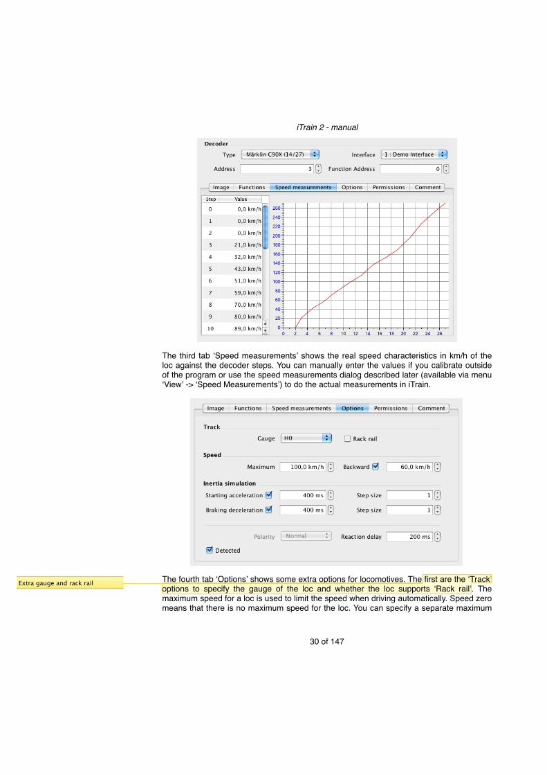
The third tab ʻSpeed measurementsʼ shows the real speed characteristics in km/h of the loc against the decoder steps. You can manually enter the values if you calibrate outside of the program or use the speed measurements dialog described later (available via menu ʻViewʼ -> ʻSpeed Measurementsʼ) to do the actual measurements in iTrain.
The fourth tab ̒ Optionsʼ shows some extra options for locomotives. The first are the ̒ Trackʼ options to specify the gauge of the loc and whether the loc supports ʻRack railʼ. The maximum speed for a loc is used to limit the speed when driving automatically. Speed zero means that there is no maximum speed for the loc. You can specify a separate maximum
iTrain 2 - manual
30 of 147
Extra gauge and rack rail

speed for the backward direction, but if you donʼt it will be the same as the forward direction.Inertia simulationThe inertia simulation works by delaying the speed steps sent to the decoder. Single steps are executed almost immediately, but when a speed change requires multiple decoder step changes, the intermediate steps are sent with a delay between the step change as specified. If the decoder has many decoder steps (for example 126), it is better not to use all the intermediate steps, but use a bigger step size.You can set the inertia simulation separately for the acceleration and deceleration. The first value is the step delay and the second the step size. To disable the iTrain Inertia simulation, uncheck the check box. When activating a loc function called ʻDirect Controlʼ, the iTrain Inertia simulation is also disabled for that loc.Note: !Good values for the inertia simulation are typically between 100 ms and 500 ms. Do
not use lower values than 100 ms, because that does not allow a speed command to be sent by the ʻInterfaceʼ and processed by the loc before another speed comment will be sent.
PolarityThe polarity is only available for analog locs in a Dinamo system. In some cases the motor is wired differently and will always go the wrong direction. You can correct this here by setting the ʻPolarityʼ to ʻInvertedʼ.Reaction delayThe reaction delay is only used when using ʻPositionsʼ described later on in the manual. With ʻPositionsʼ you can use exact positions (for example in cm) in the block to stop a loc based on time/distance calculations. Normally there will be an offset error at the entry of a block, because calculations are relative and not absolute. By playing with the reaction delay you can correct this offset for multiple blocks.DetectionThe flag ʻDetectedʼ is normally checked for a locomotive and means that the locomotive can be detected by an occupancy feedback (see Appendix B). Only in case a loc has no train and it cannot be detected over a substantial part of its length, you have to uncheck it. This is used to release blocks earlier when using occupancy feedbacks (explained later).
iTrain 2 - manual
31 of 147
Check box for backward
Check box
Direct Control replaces Shunt

The fifth tab ʻPermissionsʼ is to exclude (ʻNo access toʼ) or only allow access to specific blocks for this loc when finding a route automatically. Use the buttons on the right to add rows and use the block input box at the bottom to change the block of the selected row. In some cases the block should / should not be accessible in a specific direction. For those cases change the ʻBlock sideʼ column as required.The sixth tab ̒ Commentʼ allows you to type in comments about the loc. You can use it to put in maintenance remarks, info about the loc in real life or anything else you find useful.
Loc controlThe ʻLoc controlʼ is used to have full control over the loc while at the same having all the information available in a nice way. It consists of three tabs.
The first tab ʻControlʼ is the main tab for directly controlling the loc. To select a loc in the ʻLoc controlʼ you can use the drop-down box (only the active locs are shown) in the left upper corner or you can select it via the ʻLoc overviewʼ (described later). You will get a picture of the loc, the current signal state it is facing in the block, a speed control, the current block of the loc, some route info, the decoder step, the direction and all the loc function states.To modify the speed there are several options:• Move the slider that represents the decoder steps. Double clicking the slider will stop the
loc.• Use the scroll-wheel of the mouse while the mouse is positioned in the ʻLoc controlʼ to
change the speed in decoder steps.• Use the ʻ-ʼ key to decrease the speed and the ʻ+ʼ button (or ʻ=ʼ button so that you donʼt
need the Shift key) to increase the speed. The speed will be changed to the previous or next speed that can be divided by 5. For example, starting with speed 72 km/h the following values will be 70, 65 for ʻ-ʼ or 75, 80 for ʻ+ʼ.
• Use the number (0-9) keys on the keyboard to set the speed from 0 to 90 km/h in steps of 10 km/h and use the Shift key in combination with these keys to set the speed from 100 to 190 km/h.
iTrain 2 - manual
32 of 147
Add some to make it complete

The speedometer shows the real speed in km/h according to the speed measurements. In case of no speed measurements the maximum decoder speed is considered to be 140 km/h. In the gray rectangle of the speedometer you see two speeds at the top: the desired speed (as set with the keys or by the program) at the left and the real speed that the loc is driving on the right. These two speeds may be different if the desired speed cannot be matched exactly with a decoder step. In that case the decoder step is chosen whose real speed closely matches the desired speed while at the same time not topping it by more than 5 km/h (to prevent it from going much faster than desired). Below the speeds you can see the total time (hh:mm:ss) and total distance (meters) travelled by the loc. Of course the distance calculations only work correctly if the speed measurements have been done correctly and the inertia settings in your loc decoder have been set to a minimum.The rounded yellow/orange bar on the speedometer indicates the range between the reduced and maximum speed of the block the loc is in. The rounded red bar indicates the range beyond the maximum speed allowed in the current block. If the loc is driving faster than allowed the pointer will highlight in red. This is useful if you are driving manually, but at the same time want to drive according to the speed limits.To change the direction of the loc you can press the direction button in the left lower corner. When using the keyboard you can use the ʻDʼ key to change the direction. This will set the speed to zero and change the direction. Another option is to use the ʻBackspaceʼ key. This will stop the loc if it is driving and change the direction if the loc is not driving.Functions can be changed by pressing the button with the function icon. For many important function types a special key is reserved, as can be seen in the popup menu attached to the ʻLoc controlʼ (right mouse click or Control key + click). Momentary functions will only be activated as long as the button or key is down. All other functions will change their state when pressing the button or key.Tip:! To use the keyboard, the Loc control needs to have focus. To give the Loc control
the focus via a key, just press F3. You can now use all the key commands. A full list of commands is available in Appendix A.
The drop-down box at the right upper corner is for setting the control type. There are three options:• Manual control - the program will not influence the loc in anyway, but it still tries to follow
where the loc is on the layout.• Semi-automatic control - the program will only reduce the speed of a loc when the train
needs to stop.• Automatic control - the program automatically sets the speed to the maximum speed
allowed by the loc and train in combination with the block, and stops the loc if necessary. This is normally used in combination with train routes (explained later).
The button will start automatic driving according to an assigned route. The button will always stop the loc and will also stop driving according to an assigned route. One of
iTrain 2 - manual
33 of 147
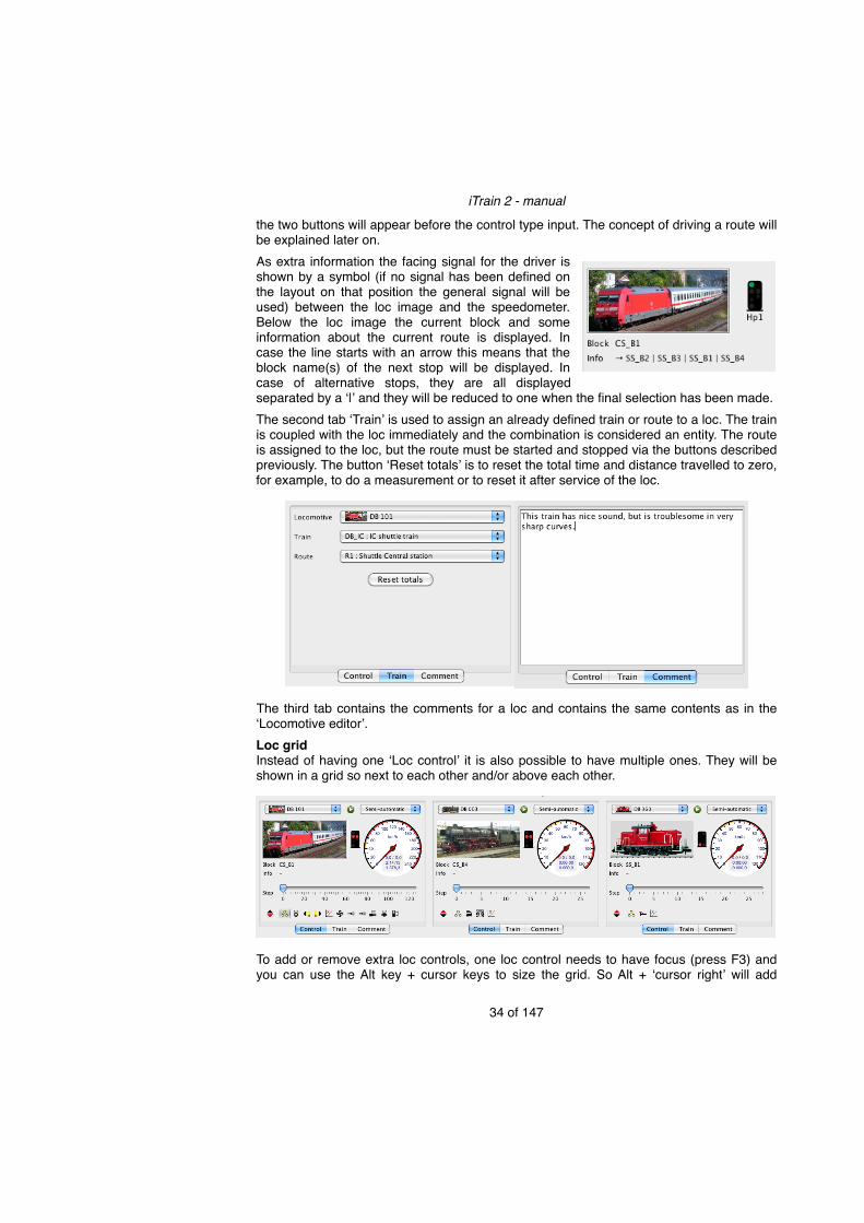
the two buttons will appear before the control type input. The concept of driving a route will be explained later on.As extra information the facing signal for the driver is shown by a symbol (if no signal has been defined on the layout on that position the general signal will be used) between the loc image and the speedometer. Below the loc image the current block and some information about the current route is displayed. In case the line starts with an arrow this means that the block name(s) of the next stop will be displayed. In case of alternative stops, they are all displayed separated by a ʻ|ʼ and they will be reduced to one when the final selection has been made.The second tab ̒Trainʼ is used to assign an already defined train or route to a loc. The train is coupled with the loc immediately and the combination is considered an entity. The route is assigned to the loc, but the route must be started and stopped via the buttons described previously. The button ʻReset totalsʼ is to reset the total time and distance travelled to zero, for example, to do a measurement or to reset it after service of the loc.
The third tab contains the comments for a loc and contains the same contents as in the ʻLocomotive editorʼ.Loc gridInstead of having one ʻLoc controlʼ it is also possible to have multiple ones. They will be shown in a grid so next to each other and/or above each other.
To add or remove extra loc controls, one loc control needs to have focus (press F3) and you can use the Alt key + cursor keys to size the grid. So Alt + ʻcursor rightʼ will add
iTrain 2 - manual
34 of 147

controls to the right (or add columns) and Alt + ʻcursor downʼ will add them vertically (or add rows). To remove loc controls, use Alt + ʻcursor leftʼ to remove a column and Alt + ʻcursor upʼ to remove rows. The focussed loc control has a border drawn around the loc image. To navigate between the loc controls use Shift + cursor keys. To change the selected loc within a loc control you can use the ENTER key to popup the list with locs and select one with the cursor keys followed by pressing ENTER again.
Loc overviewThe loc overview, in the upper left corner, shows all active locs with some of the important settings. By default a small image of the loc, the name, the real speed, the direction, the signal facing the loc, the current block and the assigned route are shown, but this can be adapted to show much more.
The and button are the same as in the ʻLoc controlʼ and one of the two buttons will appear in the column according to what is appropriate for the loc state.
iTrain 2 - manual
35 of 147
Extra navigation for loc grid

Which property is shown in the columns of the overview can be changed by the menu ʻView Columnsʼ of the popup menu of the column headings (right click or Control key + click on the table heading). It is also possible to automatically sort the locs on some of its more static properties (Address, Name, Description, Loc type, Decoder and Interface).To assign a loc of the ʻLoc overviewʼ to the ʻLoc controlʼ you can do three things:• Double click on the ʻIconʼ, ʻNameʼ or ʻDescriptionʻ column of a loc in the table.• Select a row with a loc in the table and press ʻEnterʼ.• Drag from a row on the table and drop it onto the ʻLoc controlʼ. For example drop it on
the image or speedometer.All the key combinations of the ʻLoc controlʼ are also available in the ʻLoc overviewʼ. They apply to the selected loc in the table. The same popup menu is available (right click or Control key + click on the table contents).Tip:! To use the keyboard, the ʻLoc overviewʼ needs to have focus. To give the ʻLoc
overviewʼ the focus, via key press F2. You can now use all the key commands. A full list of commands is available in Appendix A.
Traction or consistA traction or consist is a combination of locs that pull one train for extra power. In iTrain one loc is chosen to be the ʻBase locʼ and this loc controls all the other locs in the consist. Changes in speed or direction of the ʻBase locʼ will affect the other locs, but the other locs can change direction and speed independently to (de)couple them to the base loc. After being joined, only the ʻBase locʼ should be controlled to prevent problems, but the functions of the other locs in the consist can still be used.To create a traction or consist, just choose a ʻBase locʼ for yourself and drag & drop another loc on this ʻBase locʼ while holding the Control key. Extra locs can be added by dropping a loc on one of the locs in the consist. Consists can also be selected with the keyboard by first selecting the ʻBase locʼ in the (first) ʻLoc controlʼ and then, while holding the Alt key, you click on another loc in the ʻLoc overviewʼ.
In the ʻLoc overviewʼ you will see a line that indicates that two locs are connected. The first is always the ʻBase locʼ and the other locs have a grayed out speed representation to indicate that they depend on another loc. They will always be shown together independent of the sorting of the table. The position is based on the properties of the ʻBase locʼ.To remove a loc from a traction, also hold the Alt key and click on a loc in the consist. If you click (while holding Alt) on the ʻBase locʼ, the whole traction/consist will be separated. You can also remove a loc from the consist by dragging a loc from the consist and dropping it on a loc outside this consist while holding the Control key.In theory you can add any number of locs to a traction, but only locs with more or less the same characteristics will drive nicely. The program tries to match the real speeds of the locs to the base loc (and not the decoder speeds), but if the number of speed steps is low it will be difficult to find a nice match and they will not run exactly at the same speed. If the locs are connected to each other, this will in general not be a real problem, but do not try to put wagons between two locs in traction as they might derail in a curve.
iTrain 2 - manual
36 of 147

Tip:! It is also possible to create a new loc with the name of the consist and use this loc as the ʻBase locʼ. It should have decoder type ʻMultiʼ and decoder address zero.
In all places where the loc name appears (input boxes, switchboard, etc.), the name of a loc in a consist is rewritten with a number of * symbols before or after the loc name to indicate other locs in the consist. So ʻNS 1720*ʼ means it is the ʻBase locʻ of a consist of two, and ʻ*NS 1855ʼ means it is the second loc in a consist of two.
Calibrate loc speedIn all the settings of speed a normalized speed in km/h is used. This makes it easier to compare speeds of different locs. By default the program doesnʼt know which decoder speed step belongs to which real speed and it assumes that the maximum decoder step is 140 km/h and all the steps in between are linearly interpolated.
iTrain 2 - manual
37 of 147
To calibrate the speed of your loc, you can use the special calibration tool by going to menu ʻViewʼ -> ʻSpeed measurementsʼ. Speed measurements need two parameters: distance and time. The time is measured by the program, between two sensors or feedbacks. A feedback will normally be a part of a track that is isolated and may have a length of itself. Not every feedback has the same length. The ʻDistanceʼ measured is from the start of ʻFeedback 1ʼ to the start of ʻFeedback 2ʼ, so the length of ʻFeedback 1ʼ plus the distance between the feedbacks (see ʻfrom 1 to 2ʼ). The next measurement will probably be in the other direction and includes the length of ʻFeedback 2ʼ, but not that of ʻFeedback 1ʼ (see ʻfrom 2 to 1ʼ). Tip! Feedbacks have not been described yet, but you can define a feedback via the
main menu ʻEditʼ -> ʻFeedbacksʼ (or Shift + Command + F2). For more on feedbacks check out Appendix B.
To do speed measurements, select one or more rows with speed steps in the measurements table and press ʻStartʼ. All buttons will be disabled except for the ʻStopʼ button until all selected steps have been measured. A clock icon will appear in front of the value that will be measured. When the first feedback is activated the icon will change into a green arrow to indicate that measurement of this value has actually started. When the second feedback is activated the individual step measurement has been done and the icon will change into a ʻcheckedʼ icon. The loc will drive on until the second feedback has been released so it is in position for a next measurement. When multiple rows have been selected the next value will be measured until all the values have been measured.Note:! The order of selection is important when selecting multiple rows and determines if
the steps are measured from low to high or high to low.The box ʻChange directionʼ indicates that the direction of the loc will be changed between two step measurements. Only uncheck this if you are testing with an oval kind of track in which the loc will be running in the same direction for all measurements. If a loc has substantial different speed measurements in both directions, it is also possible to use direction specific measurements. In that case an extra column will be added to the ʻSpeed measurementsʼ table to separate the forward and backward speed measurements.Note:! The measurements are first done in the window and are only applied to a loc if the
ʻAppliedʼ button is pressed. Use the ʻClearʼ button to clean the table before doing measurements if the speed settings of the decoder have changed.
At any time during the measurements you can press ʻStopʼ to abort them. The ʻDirectionʼ button changes the direction of the loc in case that is necessary before starting a measurement. When doing the speed measurements one at a time, you can use the ̒ Nextʼ or ʻPreviousʼ button to measure the speed for the next or previous decoder step. The direction is automatically changed and the speed of the loc will be set correctly.Note:! Cells can also be edited by hand. To clean a value, you have to select a row and
press the ʻDeleteʼ key.It is not always necessary to measure all steps, and values can be left empty or zero. Always measure the first step for which the loc starts to move. This is the minimum step. All decoder steps before the minimum will not be used by automatic control and are considered idle steps. The last step with a value greater than zero is considered to be the maximum step. All steps that are left empty or zero between the minimum and maximum speed will be interpolated as soon as the ʻApplyʼ button is pressed.
iTrain 2 - manual
38 of 147

Note: All speed measurements should increase with every step to make them useful in controlling the loc. You can check this easily in the graph. If the values are not increasing, they will be sorted after pressing ʻApplyʼ and after the optional interpolations.
Note:! The loc function ʻDirect controlʼ will be activated when doing speed measurements to disable the inertia simulation in the decoder. The loc will get to the measured speed faster and it will brake faster giving a more precise measurement and taking up less track space for high speed measurements. Take care that the ʻDirect controlʼ function doesnʼt reduce the speed. In that case change the type of the function to ʻSlowʼ.
iTrain 2 - manual
39 of 147
Direct control
Direct control

SwitchboardThe switchboard is intended to control all the switches in your layout and to see what is happening with every train. As every layout is different in size, the switchboard has some ways to handle a large layout on the screen:1. Multiple tabs to show different parts of your layout directly. 2. Separate zoom control per tab.3. An optional overview per tab.4. The option to use a ʻWideʼ layout view.Before the details about creating a switchboard are explained, we first explain how to use a switchboard. You can try it with the demo layout (demo.tcd).
ZoomTo zoom in on the switchboard, there are several options:1. Use the zoom box or the zoom buttons on the toolbar (on the upper right corner).2. Use the scroll wheel of the mouse in combination with the Control or Command key to
zoom in or out at the location of the mouse pointer in the grid.
3. Use the popup menu via the right mouse button (or use Control + click) and go to the ʻZoomʼ sub menu.
The grid on the switchboard can be switched on and off via the popup menu (shortcut Command + G).
QualityThe option ʻAnti-Aliasʼ should always be switched on unless your graphics processor is quite old and slow. It will make all drawing more smooth. It is checked by default.The option ʻInterpolatedʼ enhances the quality of imported images in the switchboard when being scaled. It will degrade the drawing performance and is only recommended on systems with very good graphics performance. It is unchecked by default.
iTrain 2 - manual
40 of 147

OverviewThis overview option in the popup menu of the switchboard adds an extra overview pane at one side of the switchboard (for example at the bottom with ʻOverview southʼ) or in a separate window.
In the overview the whole switchboard is shown with a rectangular box that shows which part has been zoomed in. This is very useful if your layout is quite big and you want to control only a part of it, but at the same time keep an eye on the whole and be able to switch to another part very easily. There are two ways to manipulate the visible part in the switchboard via the overview:• You can drag the box in the overview to move the zoomed in area.• You can select an area in the overview with the mouse (starting with a selection outside
the current box, to prevent moving or using the ʻShiftʼ-key) to show what should be shown in the switchboard. After selecting an area it might change to keep the aspect ratio of the switchboard space.
Layout ViewNext to the standard layout there is also a wide layout where the whole width of the window is used for the switchboard and the loc controls are put below the switchboard. This makes more space for all the columns in the ʻLoc overviewʼ and is also useful for layouts that are very wide but do not need the full height of the screen. It is available via the menu ʻViewʼ -> ʻLayoutʼ -> ʻWideʼ.
iTrain 2 - manual
41 of 147

Controlling SwitchesEvery switch (an accessory like a turnout, a feedback or a track route) can be (de)selected or changed by single clicking it. For different objects the behavior might be slightly different:• For turnouts it will change from straight to branch or the other way. A
special case is a three way turnout that is actually considered as being two turnouts that cooperate. If the state of one of the two turnouts is branch it will go to straight. If the state of both turnouts is straight the change depends on which side you click and it will only change this side of the turnout. In case you want to select a state directly, just press down the mouse button on the turnout until a popup with all the states appears, and select one.
iTrain 2 - manual
42 of 147
Popup with all states

• Signals with two states just change their state. In case of more than two states the signal will go through all states in a specific order (Hp0/Hp00 -> Hp0/Sh1 -> Hp2 -> Hp1) to restrict less every time. With the Shift key the signal travels in the opposite order, restricting more at every click. Combined signals are actually two signals and depending on which part is clicked they will change accordingly.In case you want to select a state directly, just press down the mouse button on the signal until a popup with all the states appears, and select one.
• A relay will toggle its state on/off or red/green.• Decouplers will be activated as long as the mouse button is held down and be
deactivated when the mouse is up again (if the underlying system supports this and else they will be activated for the configured time period).
• A turntable will rotate to the clicked position. More details are described later on.• A transfer table will shift to the clicked position. More details are described later on.• Track routes (described later) are activated and deactivated indicated by their icon, but
they can only be activated if they donʼt conflict with reservations already made on accessories in the track route.
• Feedbacks are toggled by clicking when the control system is offline, but if your control system is online it will set the feedback according to the state read from the interface and you cannot change it.
• Blocks cannot be switched and in this case a dialog pops up to select the loc that is in the block (or no loc) and the block to which the loc is or will be driving. The first option is the block on the preferred driving direction (ʻNext sideʼ) and the second option the block on the opposite side (ʻPrevious sideʼ). The third option is only selected if iTrain doesnʼt know the direction. It is recommended to always set it to known direction for correct behavior of block following and route control.You can also deactivate the block by deselecting the ʻActiveʼ box so that it is not used in automatic route control and visually disabled in the switchboard.
• Direction arrows indicate in which direction a loc is going in the block. When you click on it the loc is turned and the arrow will be reversed. If the loc direction on the track does not match the direction of the arrow, you can Shift + click on the arrow. By doing this the arrow will be reversed without changing the direction of the loc itself so that they are
iTrain 2 - manual
43 of 147
Popup with all states

synchronized again. It has the same effect as choosing another direction in the dialog above.
You can also attach a loc to a block by drag & drop. You select a loc from the ʻLoc controlʼ, ʻLoc overviewʼ or from the switchboard itself and drop it onto a block. A popup menu will appear and you have to select ʻSetʼ. When you are holding Alt (or Control) while dropping the loc, it will be set directly without showing a popup menu. The direction of the loc is set to the preferred direction and can be adjusted, if necessary, by clicking on the direction arrow of the block. Tip: !Per switchboard tab every switch can be assigned a key combination to simulate the
mouse down/up with a key press/release (see key mappings later on). Use the F4 key to give the switchboard focus so that key events are not absorbed by other parts of the application.
Create or edit the switchboardTo create a new switchboard or to edit a current one, select from the menu ʻEditʼ -> ʻSwitchboardʼ or press Command + F4. If you do this for the first time you will be asked to enter a name for the first tab. You can modify it later, so if you donʼt know or only need one tab, just enter ʻMainʼ.
You will now see the above screen. The switchboard is at the centre. At the top you see a toolbar with some actions. On the right side is the toolbar with two columns with all the elements you can put on the switchboard. On the left side there is an optional ʻBrowserʼ with all objects currently defined in iTrain that may be or are attached to the switchboard. In the grid you see the cursor shown as a red rectangle that you move with the cursor keys or by clicking in the grid with the mouse.To draw elements in the switchboard the preferred way of working is to select an element on the right (by mouse or better with the keyboard), turn it into the right position and then go to the switchboard and press ʻSpaceʼ to add the element. You can continue by selecting another cell with the arrow keys and pressing ʻSpaceʼ again. Elements can be rotated in the drawing as well as on the element toolbar.
iTrain 2 - manual
44 of 147
New drag & drop via popup menu.

To change the size of the grid, you have to use the Alt key in combination with the arrow keys: ʻLeftʼ or ʻUpʼ to decrease the grid size in horizontal and vertical direction, and ʻRightʼ and ʻDownʼ to increase the grid size in horizontal and vertical direction. Elements outside the grid are not removed but are just not visible anymore.It is also possible to double click the element on the element toolbar to add an element to the switchboard. However, this slows down the drawing process when having to add multiple elements, because you continuously have to change the focus between toolbar and switchboard. Try to learn some of the key commands and you will be able to draw your layout very quickly. In Appendix A all the key commands available are described.When using the keyboard to enter commands, the focus is important. The best practice is to keep the focus on the switchboard (highlighted cursor) and select elements from the toolbar via key combinations. When you are holding the ʻControlʼ or ʻCommandʼ key you are navigating through the toolbar:• Cursor Up/Down to select the items on the element toolbar.• Cursor Left or ʻRʼ key to turn the selected element on the toolbar counterclockwise in the
preferred direction.• Cursor Right or ʻTʼ key to turn the selected element on the toolbar clockwise in the
preferred direction.From the switchboard you can now easily edit the grid:• Cursor keys to move the cursor in the grid.• Space key to add an element from the toolbar to the switchboard. • R or T key to turn an element in the switchboard counterclockwise or clockwise.• Alt + cursor keys to change the size of the grid.• Shift + cursor keys to select an area of the switchboard.• Shift + Alt + cursor keys to change the size of elements that can cover multiple cells.• Shift + Control or Command + cursor keys to move a selected element or area over the
switchboard.• Delete or Backspace key to delete an element. Only the element on top will be deleted if
one cell is selected. If the selection contains multiple cells, all layers will be deleted.• Shift + Delete or Backspace key to delete an element. Only the element below will be
deleted if one cell is selected and two elements are drawn on top of each other. If the selection contains multiple cells all layers will be deleted.
• Command + X to cut the current selection and copy it to the clipboard so that it can be pasted later.
• Command + C to copy the current selection to the clipboard so that it can be pasted later.
• Command + V to paste the elements on the clipboard at the cursor. If the elements do not appear where they should do, you can move them again with Shift + Command key + cursor keys or delete them with the Delete or Backspace key to undo the paste operation.
• Command + Z to undo a move, a cut or a delete. Once the selection changes, you cannot undo it anymore.
iTrain 2 - manual
45 of 147

Once an area (more than one cell) of the switchboard has been selected, you cannot use the curve and turnout elements from the toolbar anymore. Select a single cell to be able to use all elements again.
Tip:! The popup menu (click right mouse button) of the switchboard in edit mode contains some of these commands (with their key equivalents). The same zoom functionality is available in edit mode, only without the overview function.
ToolbarThe toolbar on the right may contain more elements than your screen can display. The elements are grouped. Via the popup menu (right click) you can select which groups are visible. If your space is limited, it is recommended to deselect some of the elements, for example, hide some signals.Once the focus is on an element in the toolbar, the following key commands can be used:• Cursor Up/Down to select the elements.10 • Cursor Left or ʻRʼ key to turn the selected element
counterclockwise in the preferred direction.• Cursor Right or ʻTʼ key to turn the selected element clockwise in the preferred direction.The track elements are to draw the track. The first element is the straight track and the second and third are both a curved track. The fourth element is the arrow that indicates the direction the train is driving. Add at least one per block if possible. The fifth element is for a dead end track and the sixth is a closing element, if a track is continued on another tab. This closing element can be used as a button to jump to another tab when all the block definitions (explained later) are set correctly.Note:! If the train is allowed to drive in both directions, just select one direction or
iTrain 2 - manual
46 of 147
10 With respect to navigation the two columns should be regarded as one long column with the top of the second column coming after the bottom of the first column.

select the preferred direction, but do not put two arrows in the opposite direction. In the block properties (explained later), you can define which directions are allowed in the block and if necessary the element will change into a double arrow automatically.
The turnout elements are just a preselection of some of the possible types of turnouts. You can change the type later on by double clicking the turnout and selecting a type (so single slip is also possible). The first six have an angle of 45 degrees and the last cross has an angle of 90 degrees. You cannot change the angle afterwards, so only for 90 degrees crosses select the last element.The ʻOther switchesʼ are a mixture of switches that are neither turnouts nor signals. The first is a feedback and can be a reed contact, occupancy feedback or manual button on your layout or control panel. The second element represents the block. It can be used to change block properties and it is used as the display of the block to show a name, speed and waiting time and it may cover more than one cell. In edit mode it will show the name of the block if the zoom level is 125% or more. The third is related to the track route and can activate and deactivate a manual track route. The fourth element is the decoupler track to split trains manually. The fifth element represents a relay with two states: On (=yellow) or Off (=gray), or State A (=green) or State B (=red), depending on the type. The sixth element with a lot of track connections represents a turntable and the last one represents a transfer table or traverser.Tip: ! The block element grows dynamically and may cover more than one cell
when a name appears into it. Take this into account when drawing your layout, and do not put other non-track elements next to it that may be covered and will not visible anymore at that time.
There are four signal element groups for German, Swiss, Dutch and Belgian signals. Just as with the turnout elements, the shown signal elements are just a preselection and more types are available by putting the signal on the switchboard and changing the type. There is also a ʻGeneralʼ signal which does not represent any national railway system. It supports all states that are used internally by iTrain and can be used if no other specific signal matches your needs.
The signals are drawn on a straight track so that it is always clear to which track they belong. Note:! Signals belong to the block in which the train will stop and not to the block they are
protecting. This is a more practical decision to make it easier to define a situation where blocks are connected by a turnout and the signal is placed before the turnout, but is protecting the block after the turnout.
iTrain 2 - manual
47 of 147

The ʻDraw elementsʼ group contains elements to enhance the switchboard. They can cover multiple cells in both directions and the best way to put them on the switchboard is by first selecting an area and then adding the element.The first is for adding text to the switchboard. The second is to draw a platform next to a track, for example in a station. The third called ʻStationʼ is to group cells together to indicate that they belong to a station or something else. The fourth element can be used to draw buildings or houses (schematically). The fifth element is for inserting external images. Images will impact the drawing performance of the switchboard so it is recommended to keep them small. Do not use megapixel images of your photo camera, but downscale them first with another program. When no external image is selected (empty file name) the iTrain logo will be shown.Tip: ! To change the size of ʻDraw elementsʼ in the switchboard, you have to put the
cursor inside the element and use Shift + Alt + cursor keys to change the width and height. To always stay within the element when making an element smaller, it is best to put the cursor in the left upper corner of the element.
LayersThere are no specific elements for tunnels and bridges, because you can draw elements on top of each other. When you draw a new element over another element in the same direction, then it will replace the current element. If you draw it in a different direction, then it will be drawn on top of another element with a kind of transparent gray bridge element.
If only a single cell has been selected, then actions like delete, move, copy will act on the element on top. If more than one cell has been selected, the actions will act on all layers.Tip:! In case you see the gray layer drawn on some elements, but there is no purpose for
two layers, you probably have put two elements on top of each other, but afterwards turned the element on top in the same direction as the one below. This is an error and may give unwanted results later on. You can correct it by selecting the cell and press Shift + Delete to remove the element below. Now the gray layer should disappear.
iTrain 2 - manual
48 of 147

When you control the layout, it is no problem to switch an element (for example a turnout) that is below a normal track element. Only the top most switchable element is switched and so non-switchable elements on top of switchable elements are not a problem, but prevent two switchable elements on top of each other if you want to be able to control them manually.BrowserThe browser on the left gives on overview of all the control objects defined in iTrain that can be or are attached to elements in the switchboard. You can assign control objects to a switchboard element by drag & drop. Normally, you immediately create a control object together with the switchboard element, but sometimes control objects are already available, but not attached to switchboard elements, for example, when they are already retrieved from your command station (ECoS or CS1).Tip:! The browser can be hidden by using the ʻBrowserʼ button on the toolbar to get more
space for the switchboard. Hitting the same button again will bring up the ʻBrowserʼ again.
In the browser you can rearrange control objects by drag & drop within the browser or you sort the objects by name by double-clicking on the column header. You can also remove control objects that are of no use anymore, but be careful with this, because once deleted you cannot restore them anymore. Removal of an object can be done via the popup menu (right click) or via the ʻDeleteʼ or ʻBackspaceʼ key.To select an object in the browser via the switchboard, you have to use Command + double-click on the element in the switchboard, or use Command + ʻEnterʼ. To find and select an associated element in the switchboard that is attached to an object in the browser, you can just double-click it or select it and press ʻEnterʼ in the browser.
iTrain 2 - manual
49 of 147

TemplateYou can also create new control objects based on other control objects via the ʻTemplateʼ action in the popup menu of the browser (right click). This is useful if you have to create multiple objects (for example turnouts or feedbacks) with almost the same name and description, but only with another number in it. You first select a control
object from the browser that is used a base definition. Then you select ʻTemplateʼ or you press ʻTʼ. In the presented dialog, you put a ʻ#ʼ character where the number should be inserted and in the ʻRangeʼ section you define the numbers that will be generated. In the example, 4 signals will be created with the names SS_S1, SS_S2, SS_S3 and SS_S4 and with a description with the same number in it. Other properties of the base object will also be copied except for the ones that are naturally different, such as address, comment and other things that are unique for every object, such as length.If the ʻCorrect existing oneʼ flag is checked, then also existing control objects will be changed so that they now have the same properties as the reference.Tip:! The ʻTemplateʼ action can be used to create many turnouts, signals and feedbacks
that are almost the same, such as in a shadow station. You only have to add the address manually. Even if you have already created these more or less equal objects manually, you can use ʻTemplateʼ to assure that.
Assign control objectsIn the switch board you can draw turnouts, signals, feedbacks and so on, but these drawing elements must be attached to their underlying control objects. For every control object there is only one object identified by its name, but it can be drawn multiple times on the switchboards, for example in different tabs. You can create and/or attach the control object to its viewing element in the switchboard by double-clicking the element. A dialog with two tabs will be shown:• The first tab shows the properties of the board element or viewing element. You can
select a control object from a list with already defined objects that you want to attach to it, or select ʻ<No Item>ʼ if you want to define a new control object on the fly. If you change the selection it will automatically select the second tab to edit its properties.
• On the second tab you can change the properties of the selected control object or add the data of a new control object.
iTrain 2 - manual
50 of 147

For example, when you double click a three state signal element, the ʻSignal propertiesʼ dialog shows up. You have to select one from the drop down box (for some interfaces a list may already be available from your command station) or go to the second tab and enter a new signal.Key mappingsTo assign a key combination to an element, you can use the key mapping feature. Just select the ʻKeyʼ box and use the key combination you want to use, including modifier keys like Shift, Control, Alt and Command. The text starting with ʻCodeʼ should change to represent the pressed key combination. This key combination is only valid on the tab of the switchboard where you assigned it, and doesnʼt belong to the control object itself. This way you can reuse key combinations on different tabs, for example for different stations.Tip: ! Make sure you do not override an already existing system or program key
combination, as you might get unexpected results. The ʻEscapeʼ key is to remove an existing key combination and cannot be used in key combinations, because it is reserved to ʻStopʼ the system.
When you press ʻOkʼ on the dialog, the changes on the control object are stored in the object even if you later cancel the drawing in the switchboard editor.
iTrain 2 - manual
51 of 147

Accessories
For all accessories you normally have to fill in the address box. If the accessory, for example a signal, does not really exist in your layout, but you want to add it to the switchboard (for example for hidden tracks) to show the internal state of the block, use address zero or leave it empty.For a three or more state accessory you have to enter two addresses. If you need more than two addresses you have to check the ʻUse rangeʼ. In that case the address range is from the first address until (and including) the second address. In both cases a ʻConnected toʼ box is added with option ʻBothʼ, ʻGreenʼ or ʻRedʼ, because the last address can be used half in case of an odd number of states.For example, a three way turnout is one accessory with two addresses. The first address is for the right turnout and the second address for the left turnout. For ʻConnected toʼ you select ʻBothʼ.The ʻActivation timeʼ box specifies the time between the activation of the accessory and the deactivation and must normally not be filled in. ʻDefaultʼ must be selected to use the default of the interface as specified in the Interface editor. In some cases you might want to divert from the default settings and you can fill it in here.
iTrain 2 - manual
52 of 147

The state mapping tab allows you to exactly specify the outputs on the decoder that will be activated for every state. For every accessory and turnout they will have a good default value so that you donʼt have to change it in most cases, but you can if you want to. You can switch at most four outputs for every state change (for example, for a three way turnout you need two to set both sides). You can select from the addresses specified earlier. This way the mapping order is independent from the address and when you change the address the mapping will change accordingly.The ʻEnabledʼ column makes it possible to disable a state when it is no longer possible to select that state due to a mechanical or electrical defect (for example the coil doesnʼt work or a wire is broken) or when the state is not supported by your accessory. Just keep the outputs settings so that you can continue when the defect has been fixed. Disabling a state will have effect when changing the state in the switchboard manually, but also when using train routes. Train routes will not consider this state an option anymore and will choose another option if available (in case of alternative blocks).In most cases you will use the ʻState mappingʼ to change the outputs of a turnout that was connected the other way around. You can select the two states for which the outputs need to be swapped, and press ʻSʼ or use the popup menu. In case you only have two states, you donʼt have to select them first.Output DeviceDinamo users will see an extra ʻOutput Deviceʼ box to select if the accessory is controlled by the ʻPM32ʼ, by an ʻOM32ʼ command, an ʻOM32 Pulseʼ, an ʻOC32 aspectʼ or in case of an old RM-H, by the parallel outputs. Other OM32 or OC32 users will choose the OM32 or OC32 11 as an interface and will see the same ʻOutput Deviceʼ box with the choices ʻOC32 aspectʼ, ʻOM32ʼ command,
iTrain 2 - manual
53 of 147
11 You should only choose OC32 if you use the USB-RS485 converter and all devices on the RS485 bus are OC32 devices.
New OM32 Pulse

ʻOM32 Pulseʼ and ʻDecoder63ʼ12. When selecting OM32 or OC32 only one address box will appear that refers to the first output used by the accessory. This address starts with value one for the first output (zero means no output used).So when an accessory is connected to an OC32 you can select to use either the OM32 commands generated by iTrain (easy, but less flexible) or the preprogrammed ʻAspectsʼ in the OC32 that have been created with the OC32config tool. In case the accessory has been connected to an OM32, always select ʻOM32ʼ or ʻOM32 Pulseʼ.Tip:! The ʻOM32 Pulseʼ option generates only short pulses on the output like an ordinary
accessory decoder or a PM32. You can use left over outputs on the OM32/OC32 for some accessories that need this, instead of buying a separate decoder.
The number of outputs used in the OM32 depends on the type of accessory. For signals it is determined by the outputs used in the ʻState mappingʼ table. In the example 5 outputs are used for the LEDs in the signal. Red left = 1, Green = 2, Yellow = 3, White = 4, Red right = 5. For turnouts, relays and decouplers only one output is used that is switched like a standard relay (on or off).Cross turnoutsThe cross is a special object that normally has no address (leave it empty or zero), but it is considered a turnout, because it can have two states on the screen (but only one on the layout). iTrain needs to know which direction is supposed to be used so that it can set the signals accordingly.
iTrain 2 - manual
54 of 147
12 A special turnout decoder for 63 turnouts that can be controlled by 8 outputs of the OM32 or OC32. The address ranges will be 1.1 - 1.63, 2.1 - 2.63, 3.1 - 3.63 and 4.1 - 4.63 for the first OM32/OC32, so one address is skipped every 64 positions (*.64) to better align them as can be seen in the Keyboard.
New OM32 pulse

The normal cross turnout is still there for backwards compatibility, but it is recommended to use the double slip that can have two addresses and four states, even if you have a basic cross turnout with one address on the layout. In that case only use the first address and leave the second address empty. You also have to set the state mappings so that both ʻStraightʼ states map to the same output and both branch states map to the same output (see picture). Now you can select four directions in the screen, but in the layout it uses two states. The advantage is again that the signals can be set correctly depending on the direction that is selected in the screen.The sides of a cross are called A, B, C, D (clockwise starting in the upper left corner) so the possible directions are ʻStraight ACʼ, ʻStraight BDʼ, ʻBranch BCʼ and ʻBranch ADʼ.Turnout state feedbackBy default a turnout is switched, and after the activation time it is considered to be in the preferred state. If you want to guarantee that the turnout has been switched correctly, you can connect feedbacks to the turnout. To be able to support, for example, feedback for a three way turnout, the feedbacks are not attached to the states itself, but to the outputs. This way it is possible to detect which turnout has changed. So there is a relation between ʻState mappingʼ and ʻState feedbackʼ, to be able to find back the turnout states.
The ʻActivatedʼ flag in the third column determines if the feedback will be activated or deactivated when the turnout reaches its end state. Normally every output would have its own feedback. It is however possible to use one feedback for a turnout and attach it to both outputs, but one time when its activated and one time when its deactivated.Warning signalsA warning signal shows the state of the following home signal, only it is placed earlier on the track. In case the warning signal has the same address as the home signal, you should
iTrain 2 - manual
55 of 147

not define a signal object for the warning signal, but just use the home signal object. This can be achieved by selecting the home signal from the drop-down box on the ʻBoard itemʼ tab. You can also do it in the switchboard, by dragging the home signal element and while holding the ʻControlʼ key (or Alt) drop it on the warning signal element. Internally, both elements on the switchboard will now have one underlying signal object.If the warning signal has its own address, it should have its own warning signal object. In the block definitions later on, you can attach this kind of warning signal to a block to automatically switch it to the correct state.
Combined home and warning signal elements represent two signal objects in one visual element. Depending on where you click, you will have access to the home or the warning signal. They should be treated as if you added two signal objects. In many signaling systems it is common that when the state of the home signal is stop (red), the warning signal will not show its state. This effect can be achieved for a warning signal with its own address by enabling the ʻNoneʼ state on the ʻState mappingʼ. If the ʻNoneʼ state is available then it will be used when the main signal is stop (red).OptionsThe tab ʻOptionsʼ contains some other settings for an accessory.
The option ʻState delayʼ specifies the extra time that should elapse before an accessory is considered to have changed state after the command has been given. So it is added to the activation time. If there is no activation time (for example with an OM32/OC32), it is the time it takes to change the state of the accessory.Tip:! Servos normally take more time to change their state than the actual command to
the interface. To prevent trains driving over turnouts that are not completely set, you can specify the ʻState delayʼ.
Turnout optionsThere are some additional options for turnouts. First you can specify the ʻLengthʼ of the turnout. This field should contain the minimum length for all states in case they are not the same. Now it is possible to calculate a (minimum) total length passed between blocks that can be used to release blocks earlier for long trains that span multiple blocks with many turnouts in between.
iTrain 2 - manual
56 of 147
New turnout options
New option ‘State delay’

The tab ʻOptionsʼ contains two additional fields for turnouts. The ʻOccupancyʼ feedback notifies if part of the train is still on turnout. In case this feedback is ʻOnʼ, the turnouts will not be released. One feedback can be assigned to multiple turnouts so that when the turnouts are interconnected you donʼt need a feedback for every turnout.The ʻSpeed typeʼ affects the signal state before the turnout. Type ʻStandardʼ will show a restricted state (for example Hp2) when the turnout state is ʻBranchʼ; ʻFastʼ will never show a restricted state and ʻSlowʼ will always show a restricted state.
FeedbacksFeedbacks or sensors are the eyes of the system. They notify which part of the track is occupied or what point on the track was passed. In general, they can cannot see who was responsible for it, but only that something happened. Also see Appendix B for more background information on feedbacks.
Feedbacks have an address, an interface, a type and depending on the type a length. It is
iTrain 2 - manual
57 of 147
Specify the type

recommended to specify the type especially when it is of type ʻOccupancyʼ, because it will affect the behavior in blocks.
For a feedback of type ʻOccupancyʼ you can enter a length of the feedback. This length is used to calculate the positions of the feedbacks in the block and will be used to release previous blocks earlier.The ʻInvertedʼ box allows to interpret the feedback the other way so that ʻ0ʼ is occupied and ʻ1ʼ is free. This is the default setting for a feedback of type ʻLight barrierʼ. When a feedback is inverted you see the inverted value in the switchboard. In the feedback monitor (mentioned later in this manual) you see the original input from the interface on the border/edge of the element and the inverted value at the inside. The ʻDelayʼ of the feedback when switching them on or off is normally specified per interface, but you can override the values here for a specific feedback. When ʻDefaultʼ is checked, you will see the default value in gray.
Track routesTrack routes behave like the Memory module. You can set a list of turnouts or signals in order to a specific state and they will be set and reserved as long as the track route is active. That means that they cannot be set manually anymore by clicking or by other track routes, and they are not used by train routes.
iTrain 2 - manual
58 of 147
Length is used
New Delay per feedback.

On the ʻSwitch orderʼ tab you can create the list of accessory states. The three buttons allow you to remove a row, insert a row at the selected position or append a row at the end. When filling in a row, first select the ʻTypeʼ of accessory (turnout, signal or relay) in the first column, then select an accessory in the second column from the drop down box and finally set the desired state in the third column.Tip:! First assign all your turnouts, signals and feedbacks before creating your track
routes.The last column ʻDelayʼ allows you to set an individual delay per accessory before they will be switched. This makes it possible to make a timed sequence in which, for example, light can be switched on and later on the same sequence be switched off again. The specified delay will always be used, even when the accessory is already in the right position. A value of zero means no specific delay.
iTrain 2 - manual
59 of 147

On the ʻOptionsʼ tab, some extra settings on a track route are available.The ʻRhythmʼ box specifies the time between switching the individual accessories, but only between the ones that are actually switched. By setting it to zero all accessories will be set as quickly as possible, but in many cases it is useful to keep some space so that you are sure all turnouts are set before you set the signal. If an individual ʻDelayʼ greater than zero has been specified per accessory, this delay will be used instead of the ʻRhythmʼ value.If the ʻSet Alwaysʼ box is selected, it is guaranteed that all the accessories will be switched by the interface, even when the program thinks they are already in the correct state. This costs more switching time with long lists, but prevents errors by manual changes outside the program.To reset the accessories back to their initial state after they have been released, you can use the ʻReset initial stateʼ box. It will only reset them to their initial state again if they are not reserved immediately by another track route, to prevent unnecessary switching.Track routes can also be activated or released by feedbacks (see ʻAutomatic controlʼ) that have been defined before. This way you can at least always release a track route when the train passes a specific sensor or feedback. But more advanced examples are possible, because the feedbacks will react the same way as the Märklin13 Memory (6043):• The ʻActivate feedbackʼ will not activate the track route if the ʻRelease feedbackʼ is still
selected.• When the ʻRelease feedbackʼ is deselected (freed) and at the same time the ʻActivate
feedbackʼ is still selected, it will activate the track route.
iTrain 2 - manual
60 of 147
13 Märklin is a trademark

Tip:! To activate one or more accessories via a feedback without reserving them, you can use a track route and assign the same feedback to both the ʻActivateʼ and ̒ Releaseʼ feedback. This way you can create a timed sequence triggered by a feedback.
BlocksIn reality a block system is used to prevent train collisions by assuring that only one train can be in a block at the same time. If a block is occupied, a train in a previous block must stop and wait until the block is free again before entering it. In iTrain this is not any different. Therefore you have to divide your layout into blocks taking into account that turnouts are not part of a block and are always a border of a block. Long tracks between turnouts can be split into two ore more blocks. Normally a block should be able to contain the longest train so this is the main point. Of course sometimes a block will be shorter, because it is between two turnouts, so you have no choice. If the space between two turnouts is very short, you could also consider this as no block and configure it as if the two turnouts were directly connected without a track in between.It is important to know where a train is to be able to guarantee that it will not enter an occupied block. Therefore, every block contains feedbacks or sensors to inform the block what is happening in the block. Every block is also connected to other blocks directly or indirectly via turnouts, so each block must know what its neighboring blocks are on both sides (one side may not be connected). In iTrain the sides of a block are called ʻPreviousʼ and ʻNextʼ indicating the default direction of the block from ʻPreviousʼ to ʻNextʼ. In case the block is used in two directions and there is no preferred direction, just pick one arbitrary direction. It is no problem to connect a ʻNextʼ side of one block to the ʻNextʼ side of another block if that would make sense for you.To indicate a block in the switchboard you need to assign multiple track elements (with signals and feedbacks and maybe more) to a block. An element with the white rectangle (in edit mode with an arrow for the text direction or the block name) represents a block. It is used to define the block.
In edit mode you can assign other track elements to the block by first selecting the block element and pressing the ʻBʼ key (see popup menu). Now all track elements that belong to that block are colored orange. You can now assign extra track elements to the block (not including turnouts) by selecting them and pressing ʻBʼ again. You can also do it in one step by selecting all elements belonging to the block (including the block element) and pressing ʻBʼ. To remove already assigned track elements from a block, select them and use Shift + ʻBʼ. By selecting an empty element cell and pressing ʻBʼ, you turn off the highlighting of all elements belonging to the block.Tip:! The block names will be displayed in the block elements if the zoom level is 125%
or more and you are in edit mode.In switchboard edit mode all elements assigned to a block have a kind of brown color (color in between orange and black). In a well defined switchboard in edit mode, only the turnouts are black and maybe some tracks between turnouts not belonging to a block.
iTrain 2 - manual
61 of 147
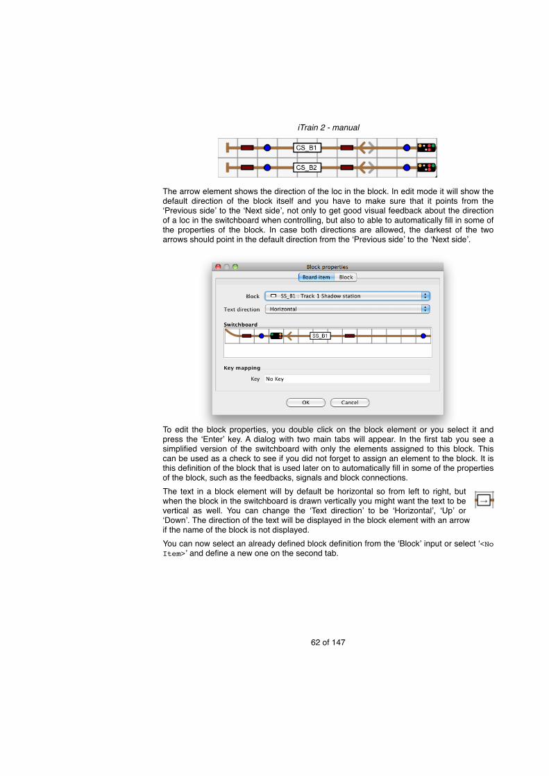
The arrow element shows the direction of the loc in the block. In edit mode it will show the default direction of the block itself and you have to make sure that it points from the ʻPrevious sideʼ to the ʻNext sideʼ, not only to get good visual feedback about the direction of a loc in the switchboard when controlling, but also to able to automatically fill in some of the properties of the block. In case both directions are allowed, the darkest of the two arrows should point in the default direction from the ʻPrevious sideʼ to the ʻNext sideʼ.
To edit the block properties, you double click on the block element or you select it and press the ʻEnterʼ key. A dialog with two main tabs will appear. In the first tab you see a simplified version of the switchboard with only the elements assigned to this block. This can be used as a check to see if you did not forget to assign an element to the block. It is this definition of the block that is used later on to automatically fill in some of the properties of the block, such as the feedbacks, signals and block connections.The text in a block element will by default be horizontal so from left to right, but when the block in the switchboard is drawn vertically you might want the text to be vertical as well. You can change the ʻText directionʼ to be ʻHorizontalʼ, ʻUpʼ or ʻDownʼ. The direction of the text will be displayed in the block element with an arrow if the name of the block is not displayed.You can now select an already defined block definition from the ʻBlockʼ input or select ʻ<No Item>ʼ and define a new one on the second tab.
iTrain 2 - manual
62 of 147

The type of the block affects how signals are treated and what the maximum speeds are. Justifications per individual block are possible via the ʻOptionsʼ tab, discussed later.The type ʻShuntʼ is meant for blocks between the entry signal and the station to make it possible to shunt. The type ʻSidingʼ is for tracks with a dead end or between turnouts to park trains. The two types ʻTurntableʼ and ʻTransfer tableʼ are special types that are automatically assigned and they should not be used outside of their context.The length specifies the total length of the block. The margin is the extra space necessary to compensate for differences in stop positions for different trains. There is a default value for the margin, based on the block type, but you can override it. The length minus the margin defines the usable length in a block. Trains that are longer are considered not to fit in the block and will not release previous turnouts and/or blocks when stopping in the block.An empty length or length zero means unknown. In that case the program will assume that all trains will fit in the block. So especially for short blocks it is important to measure the length. For very long blocks in which any train will fit, it is less important for safe train
iTrain 2 - manual
63 of 147
Better throughput
Length and Margin specified.
Block type

control, but it will be useful for better throughput in case you also specify the feedback positions.
The feedbacks, signals and block connections must be specified per driving direction (to side ʻNextʼ and to side ʻPreviousʼ). It is necessary to specify them for both directions for correct train following even when the block is only used in one direction.Note:! By default, only the signals that are attached to the block can be selected in the
input boxes. This makes it easier to select the correct one, because it is never necessary to select one outside the block. In case the block is divided over two tabs, the selection may not be correct. The ʻShow Allʼ option will fill the input boxes with all the signals available.
The ʻAuto fillʼ button can fill in most of these properties for ʻFeedbackʼ, ʻSignalʼ and ʻBlockʼ on the first two tabs automatically. It is however required that all the feedbacks, signals, turnouts and neighboring blocks that will be chosen already have a name for correct results. So it is recommended to first assign names to all these control objects and then use the ʻAuto fillʼ button to attach them to the block.FeedbackTo detect that a train is in a block, at least one feedback is necessary. One feedback allows to follow a train so that the system knows where a train is. However with only one feedback it is not possible to accurately and nicely stop the train in front of a signal easily14, because every loc has different characteristics. A stop section before a signal would solve this. If a train enters the block and needs to stop in this block, it can slow down in the main part of the block, but it will only really stop in the stop section at the end.
In this case we need an extra feedback at the side of the block where we want to stop (in HO about 20-35 centimeters, depending on the brake speed15). This feedback is called the ʻStopʼ feedback for this direction. In case you drive a block in two directions and want to be able to stop in both directions, you need to create this stop section on both sides of the block resulting in a total of three feedbacks16. The feedbacks on the sides will have a different role depending on the driving direction. When driving in a block, the first feedback will be the ʻEntryʼ feedback. The next will be the ʻBrakeʼ feedback and the last will be the ʻStopʼ feedback. For the other direction the same feedbacks will have another function. It is very common that the ʻEntryʼ feedback is the same as the ʻBrakeʼ feedback and that the ʻEntryʼ feedback in one direction is the same feedback as the ʻStopʼ feedback in the other direction.
Stop section Normal block detection
iTrain 2 - manual
64 of 147
14 It is possible to stop accurately, but only with good decoders and more configuration in both the decoder and iTrain. For example, precise speed measurements have to be done for all locomotives.
15 The brake speed is the speed of a train when it is entering the stop section. It is an option of the block.
16 Two feedbacks is also possible by not detecting the middle part and only using the side feedbacks.
Remove feedbacks, because they are dependent on the feedbacks tab.
New one feedback per block
New two feedbacks
New text
Formulated differently
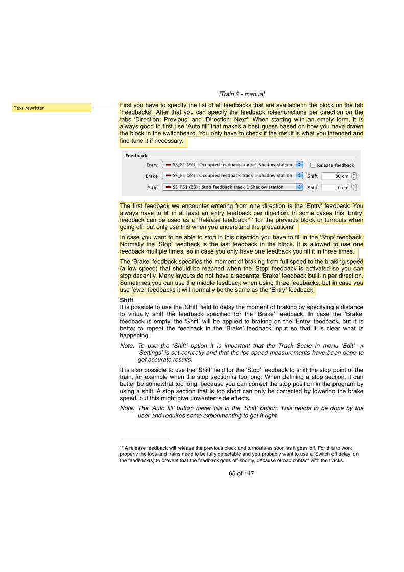
First you have to specify the list of all feedbacks that are available in the block on the tab ʻFeedbacksʼ. After that you can specify the feedback roles/functions per direction on the tabs ʻDirection: Previousʼ and ʻDirection: Nextʼ. When starting with an empty form, it is always good to first use ʻAuto fillʼ that makes a best guess based on how you have drawn the block in the switchboard. You only have to check if the result is what you intended and fine-tune it if necessary.
The first feedback we encounter entering from one direction is the ʻEntryʼ feedback. You always have to fill in at least an entry feedback per direction. In some cases this ʻEntryʼ feedback can be used as a ʻRelease feedbackʼ17 for the previous block or turnouts when going off, but only use this when you understand the precautions.In case you want to be able to stop in this direction you have to fill in the ʻStopʼ feedback. Normally the ʻStopʼ feedback is the last feedback in the block. It is allowed to use one feedback multiple times, so in case you only have one feedback you fill it in three times.The ʻBrakeʼ feedback specifies the moment of braking from full speed to the braking speed (a low speed) that should be reached when the ʻStopʼ feedback is activated so you can stop decently. Many layouts do not have a separate ʻBrakeʼ feedback built-in per direction. Sometimes you can use the middle feedback when using three feedbacks, but in case you use fewer feedbacks it will normally be the same as the ʻEntryʼ feedback.ShiftIt is possible to use the ʻShiftʼ field to delay the moment of braking by specifying a distance to virtually shift the feedback specified for the ʻBrakeʼ feedback. In case the ʻBrakeʼ feedback is empty, the ʻShiftʼ will be applied to braking on the ʻEntryʼ feedback, but it is better to repeat the feedback in the ʻBrakeʼ feedback input so that it is clear what is happening.Note:! To use the ʻShiftʼ option it is important that the Track Scale in menu ʻEditʼ ->
ʻSettingsʼ is set correctly and that the loc speed measurements have been done to get accurate results.
It is also possible to use the ʻShiftʼ field for the ʻStopʼ feedback to shift the stop point of the train, for example when the stop section is too long. When defining a stop section, it can better be somewhat too long, because you can correct the stop position in the program by using a shift. A stop section that is too short can only be corrected by lowering the brake speed, but this might give unwanted side effects.Note:! The ʻAuto fillʼ button never fills in the ʻShiftʼ option. This needs to be done by the
user and requires some experimenting to get it right.
iTrain 2 - manual
65 of 147
17 A release feedback will release the previous block and turnouts as soon as it goes off. For this to work properly the locs and trains need to be fully detectable and you probably want to use a ʻSwitch off delayʼ on the feedback(s) to prevent that the feedback goes off shortly, because of bad contact with the tracks.
Text rewritten

It is possible to stop in a block that only contains one feedback. This is, however, less precise than the option with a dedicated stop feedback, but in some cases there is no possibility for an extra feedback. You can use the same feedback for ʻEntryʼ, ʻBrakeʼ and ʻStopʼ with different ʻShiftʼ values. If the block is too short to brake in, the last feedback of the previous block can be used to start the braking. To achieve this, leave the ʻBrakeʼ feedback empty and its ʻShiftʼ zero. This is a natural option for short dead end blocks that are only used to park a loc or a very short train.Note:! A train will be stopped in a previous block when a block does not have a feedback
assigned to the ʻStopʼ feedback input and a stop is necessary. This is direction dependent so you can make it possible to stop a train in a block in one direction, but do not allow it in the other direction.
SignalIf a block knows its neighbors, then it can also calculate the state of the block signal. In iTrain you can assign signals for each direction through a block and then its state will be set automatically. It is important that you assign the signal to the block in which the train will stop and not to the block that the signal protects.
Next to the Home signal you can specify a Shunt signal that is placed in front of the home signal. The internal signal state of the block (in this direction) will then be represented by two signals. If you only have a Shunt signal you better fill it in in the Shunt field. A combined home and shunt signal should be filled in Home Signal, and the Shunt signal should be left empty.You can also assign warning signals. You should only do this if the warning signal has its own unique address (and object). We have to distinguish between two warning signals: • A separate warning signal in the block that is related to and preceding the home signal in
the same block. It should be assigned to the ʻWarning Signalʼ box above the Home signal.
• A warning signal that is part of a combined home/warning signal and is related to a home signal in a following block. It should be assigned to the ̒ Warning Signalʼ box in the ʻBlockʼ section below the ʻSignalʼ section.
BlockThe section ʻBlockʻ relates to the neighboring block when driving in this direction. At first you can specify the ʻWarning Signalʼ that informs you about the state of the signal in the block after the current one.
iTrain 2 - manual
66 of 147
Shunt signal

Secondly there is a small box ʻCriticalʼ with important functionality. If this block is marked ʻCriticalʼ it means that this block plays a critical role in the reservations to prevent deadlocks. The block will only be reserved if the block after this block can also be reserved
in one action. It should, for example, be used on a single track in the direction of a terminus to prevent a train from reserving the single track before the station if it is not possible to enter the destination block(s) in the station. By reserving the single track before the station, the trains in the station would have no possibility to leave the station anymore, causing deadlock.Note:! In general, it is not necessary to use ʻCriticalʼ on a single track divided into two or
more blocks that are bi-directional. The program will automatically detect this situation and reserve all the blocks until the end of the single track or until another reserved block in the same direction is found. Therefore it is not possible to do reservations on the single track in another direction anymore. However, it is still allowed to do reservations for other trains in the same direction that are behind so that multiple trains may follow each other on a single track and use the full capacity.
ConnectionsThe program needs to know what the neighboring blocks are for every block, for example, to follow the trains over the layout, set the signals correctly and calculate routes. Starting in a block and following one of the two directions it will optionally pass some turnouts and come into other blocks. The path to these other blocks including the turnouts have to be specified in the tree at the bottom. Only the turnouts that will make a selection between two blocks have to be specified and not the ones just joining two or more blocks into one, because they will be specified in the block on the other side of the turnout.Note:! The ʻAuto fillʼ button mentioned earlier will normally correctly fill in the block
connections, but it is good to know how you can manually do it to understand it better and to check it in case of problems or if you want to add extra relays in the path.
In the block connection tree above, for every turnout the states of that turnout are listed, with at least two items below a turnout: the first for the straight state and the second for
iTrain 2 - manual
67 of 147

the branch state. In case of one of the cross turnout types, the first two states will be the straight states. Depending on the type you can have extra branch states up to four states in total (AC, BD, BC, AD). Only half of the states will have a block or other turnout connected and the others should be left empty (shows ʻSelect a blockʼ). In case of a single slip with three states, one or two states should be connected. It all depends on the side (A,B,C,D) that is (directly or indirectly) connected to this block.
You can select a block or leave it empty or you can insert a node with a turnout, a relay, turntable, or transfer table via the popup menu of the ʻBlockʼ tree (right mouse click or Control key + click). It is always possible to delete nodes with the ʻDeleteʼ button. The ʻBlock sideʼ item specifies the side of the block in the node that is connected with the options ʻPreviousʼ, ʻNextʼ and ʻBothʼ, but this will be filled in automatically.The menu item ʻCreate connectionsʼ from the popup menu can be used to only create the block connection at one side without filling in the other properties. Normally the automatically generated block connections (via ʻAuto fillʼ or via ʻCreate connectionsʼ) are enough, but in some cases you need to fine-tune the generated settings.
You can add relay elements that will be switched when a path between two blocks is created. Every relay element has only one element below it, so that it can be inserted at any position. The state of the relay element can be set via ʻStateʼ of the popup menu. This is used by block controlled systems (such as Dinamo) to feed the turnout sections18 with power from a block depending on the path. This is a system specific topic that is not discussed any further in the iTrain manual.
iTrain 2 - manual
68 of 147
18 Mainly used for cross turnouts and anti-parallel turnouts emulating a cross turnout.

PositionsThe ʻShiftʼ values next to the feedbacks are relative values that will shift the ʻBrakeʼ and ʻStopʼ feedback virtually. So when using 10 cm for the ʻStopʼ shift, it will stop 10 cm later than it would have stopped when using the ʻStopʼ feedback without a shift.
With ʻUse positionsʼ you can stop at an absolute position in the block. When using this, the ʻShiftʼ box for ʻBrakeʼ (and for ʻStopʼ when working with one feedback) should be left zero, because both shifts will be calculated per loc based on the desired stop position and the deceleration characteristics of the loc. The start of the ʻEntryʼ feedback is considered the start of the block and is position zero. Note:! An extra ʻStopʼ feedback (optionally with a ʻShiftʼ) at the end of a block may still be
used for safety in case the calculations do not give the expected result. Make sure that the ʻStopʼ feedback is not activated before the calculated stop shift or else it might cause an emergency stop because the train has not reached the brake speed yet.
We have to distinguish two positions to stop. One because the signal is red and the train is not allowed to pass it. In this case the train should stop before the signal. In the box ʻStop positionʼ you can enter the position at which the train should stop for a signal, using a positive value when measuring from the start of the block or a negative value from the end of the block.
The other position is a scheduled stop in a station independent of the signal and should preferably be along the platform. If the block is of type ʻStationʼ, a ʻPlatformʼ section will appear at the bottom to specify the platform. The ʻStartʼ is the position of the platform from the start of the block and the ʻLengthʼ is the length of the platform itself. The ʻCenter aroundʼ box specifies the relative position of the exit on the platform. By default this is in the middle of the platform, but by checking the box before the value you can adjust it (positive value relative to the start of the platform and negative value relative to the end of the platform). A train will stop centered around this point, unless this would mean a part of the train would not be along the platform. In that case it will be shifted so that is always along the platform, but as close to the exit as possible.When using positions you normally work with one feedback or an optional second stop feedback that might not have been activated when the train stops. So releasing the previous block and turnouts on the stop feedback (if the train fits into the block) is not an option, because it might not happen until after the train leaves again. So the release will be done based on the calculated position of the train in the block. The previous block and turnouts will be released when the distance travelled in the block is more than the total length of the train.
iTrain 2 - manual
69 of 147
Note:! There is a potential danger that the loc might stop too early in the block because of dust or other bad contact with the tracks and still occupies a turnout or a previous block. The program thinks the loc is still running and the calculated distance in the block might release previous blocks and/or turnouts after some time. So to use positions safely you have to guarantee proper and good contacts with the track.
The calculations work best if your loc has cruise control and the mass simulation in the decoder is set as low as possible. In that case the loc will stop pretty precisely at the same position in a block, but probably not immediately at the specified position. Without a correction in the calculation most locs would react too late and they will run further than specified. Therefore you can set an individual ʻReaction delayʼ per loc (on the ʻOptionsʼ tab of the loc editor). The higher the value the earlier the loc will stop. By default the value is set to 200 ms, but it should be determined by trial and error and will probably be higher in practice.
iTrain 2 - manual
70 of 147

Options
In the ʻOptionsʼ tab you can specify some other settings of the block:• The ʻGaugeʼ of the track specifies the allowed gauges. Only locs and trains that meet this
gauge are allowed in this block.• A block should be marked ʻElectrifiedʼ if it has catenary, so that it can be used by electric
locs. If this is not marked, electric locs will not be able to enter the block or start from this block in a route.
• If ʻRack railʼ is checked, only locs with this same option are allowed in this block.• The ʻDirectionʼ property of the block: A block can be allowed to be driven in both
directions or in just one direction. Even if it is allowed to travel in both directions in some cases, in most cases it should be used in one direction. This is called ʻPreferred
iTrain 2 - manual
71 of 147
New Gauge
New Rack rail
Changed text

directionʼ. The single or preferred direction is always from ʻPrevious sideʼ to ̒ Next sideʼ. This ʻDirectionʼ setting directly effects the way the arrow element in the switchboard is drawn and it is also used by routes (described later) to determine what the preferred direction is.
• The ʻAutomatic signalsʼ property specifies how signals attached to the block will react on neighboring blocks. If the box is unchecked or a turnout follows, the signal is always red, unless the following block has been reserved by the same loc. If the box is selected and no turnout follows, the signal will be set to green automatically when the next block is free. By default this option is only selected for blocks of type ʻFreeʼ.
• The ʻSlopeʼ property specifies the incline of the block in percentage from the ʻPreviousʼ side to the ʻNextʼ side and uses negative values for a decline. It is meant for speed corrections for locs with no cruise control in future versions, but it is currently not used.
• If ʻDirection dependent speedsʼ is checked, you can specify different speeds per direction in the block in the next section ʻSpeedʼ. Two columns with speeds will appear instead of one.
SpeedThe default speeds in the blocks are specified in the general ʻSettingsʼ, but these can be overridden per category by checking the box before the speed. An unchecked box will show the speed value that will be used based on the default speeds. By using the ʻDefaultʼ button you can set all speeds to default at once.
The different categories are:• Maximum - the maximum speed in the block if there are no other restrictions from
signals.• Expect stop - the maximum speed when leaving the block if the train has to stop in the
next block.• Restricted - the maximum speed if the signal shows the restricted sign, for example
when a turnout is branched in the path to the next block.• Brake - the speed to which a train brakes in case of a red signal until it enters the stop
feedback.• Shunt - the maximum speed if the signal shows that only shunting is allowed.In case ʻDirection dependent speedsʼ are checked, two columns will appear with in the left column the speed in the direction ʻPreviousʼ and in the right column the speed in direction ʻNextʼ.
iTrain 2 - manual
72 of 147
New Direction dependent speeds
New Automatic signals
Direction dependent speeds

Block controlThis section is about how the track of the block is wired with the system. For all 2-rail systems you have to decide which rail is the ʻ+ʼ and which one the ʻ-ʼ. We call this the polarity. The polarity is a relative matter so we first have to define the reference. Let us assume that every track has a ʻredʼ wire called ʻ+ʼ and a ʻblackʼ wire called ʻ-ʼ. Now we look at the blocks in the direction from ʻPreviousʼ to ʻNextʼ. If the ʻ+ʼ is on the right rail and the ʻ-ʼ on the left rail we call that ʻNormalʼ polarity. If in a block has the ̒ +ʼ on the left rail we call that ʻInvertedʼ polarity. You can also choose the ʻ+ʼ and ʻ-ʼ the other way around if that makes more sense for you, but stick to one definition.
In case two neighboring blocks are wired the same (+ and -), but in the program they are defined in an opposite direction (see example above), then they have a different polarity in iTrain and one should be assigned the ʻInvertedʼ polarity.Tip:! Try to use ̒ Normalʼ polarity for most blocks. When using ʻDinamoʼ choose the option
ʻInvert total polarityʼ on the ʻSpecificʻ tab of the ʻInterfaceʼ editor (menu ʻEditʼ -> ʻInterfaceʼ) in case analog locs are going the wrong direction.
For block controlled systems like ʻDinamoʼ, you have to specify the polarity and the address of the block. This is the address on the TM-H (starting at 1, because 0 means no address).For normal digital 2-rail systems it is optional to fill in the polarity. It will probably be used in the future if relays that switch the polarity are coupled with blocks to automatically solve polarity conflicts, such as with turntables.RelayThere are two types of relays that can be coupled with a block. The type ʻA/Bʼ is intended to switch the polarity of a block as described above. This can, for example, be useful for turning loops to automatically switch the polarity, because the relay will be put into the ʻBlock connectionsʼ with a different state on both sides.The other type ʻOn/offʻ is intended to physically disconnect a block and its feedbacks from the system to park locs or trains.19 The relay will be put into the ̒ Block connectionsʼ so that it will be reserved and switched ʻOnʼ when creating a path to the block. The relay will not be released until the loc has really stopped in or left the block, so that it will not stop abruptly because the power has been switched off too early.
iTrain 2 - manual
73 of 147
19 With a purpose to share one block output (TM-H) and two detection outputs (CD-16) for multiple sidings such as with the DinaSys Turntable Control (DTC).

In Dinamo systems relays attached to blocks can be used to reduce the number of block outputs (TM-H) in shadow stations or sidings. This will only work properly if of all the relays attached to blocks with the same address, at most one will be active at a time. Internally iTrain will create relay groups to guarantee this. Attaching a relay to a block and using the button ʻAuto fillʼ should be enough to make this work. The only requirement is that the relays are controlled via the Dinamo interface (possibly via an OM32/OC32) and not via a second interface.Feedback positionsThe tab ʻFeedbacksʼ shows all the available feedbacks in the block, optionally with their position in the block. On the tab ʻDirection: Previousʼ and ʻDirection: Nextʼ you select the feedbacks that have a specific function per direction in the block. You can only select feedbacks on the first two tabs from the feedbacks that are listed in the tab ʻFeedbacksʼ. To fill the list of feedbacks, you will normally use the button ʻAuto fillʼ.Note:! Additional feedbacks that do not have another role than just an extra ʻOccupancy
feedbackʼ or a ʻRailComʼ detector can be entered here as well.
By specifying the positions of feedbacks in a block you have more information about where a train is in the block. Currently the positions are used to release previous blocks and/or turnouts earlier when the train has driven further in the block than the length of the train.Per feedback, some extra columns are shown. At first the length of the feedback in case of an occupancy feedback. This is actually a property of the feedback, but it can be edited here as well for convenience. The next four columns show Start and End position of the feedback in the block in both directions. The first two in ʻDirection: Nextʼ and the last two in ʻDirection: Previousʼ. Only the value in the first column ʻStartʼ is the actual position and will be stored. The other values like the ʻEndʼ position and the ʻStartʼ and ʻEndʼ position in the other direction are only shown here for convenience. You can enter a value for both ʻStartʼ columns depending from what side of the block you are measuring, and the other values will be calculated.Note:! To fill in the position of the feedbacks in the block it is necessary that the length of
the block has been specified first.Entering the positions can be tedious. If the lengths of the feedbacks are filled in and you either have only one or two feedbacks, or the length of all the feedbacks together is equal to the block length, you can use the ʻFillʼ button to fill them in automatically. Before you do that it is important that the order of feedbacks is correct (from ʻPreviousʼ to ʻNextʼ), and if necessary, you can adjust the order by using the buttons ʻMove upʼ and ʻMove downʼ.
iTrain 2 - manual
74 of 147
New Auto relay groups in Dinamo
New feedback positions

StationsA station is a destination where trains can stop. It contains a set of blocks that belong together. It can be used in routes that are described later on.
To create a station, select multiple cells in the switchboard and double-click the station button in the toolbar or use the keys Shift + ʻSʼ. This only creates the ʻStationʼ element. To create the ʻStationʼ object you have to double-click in the element so you can edit the station properties.
iTrain 2 - manual
75 of 147

The station consists of a type and a list of blocks. The type has to be selected, but the list of blocks can be filled automatically. In that case it will include all the blocks of a type that have a block element (white box) in the area covered by the station and matches the station type. A ̒Shadow stationʼ matches blocks of type ʻStationʼ and ʻSidingʼ; ʻPassengersʼ only matches blocks of type ʻStationʼ, and ʻCargoʼ and ʻShedʼ only match blocks of type ʻSidingʼ. It is also possible to edit the blocks manually via the ʻBlockʼ input and the buttons on the right.
TurntableThe turntable is an element to connect multiple tracks together by means of a turning bridge. This way it is possible to turn the loc. This is commonly used for steam locs. On the toolbar the turntable is just a small element, but it has been designed to be a much bigger element on the switchboard, covering multiple cells in both directions. Depending on the number of outputs used it can be useful to use 4x4 cells up to 12x12 cells for all outputs, but there is no limit.The track connections have to end in the middle of a neighboring cell. Just enlarge the turntable until it looks right by selecting the turntable and using Shift + Alt + cursor keys to size. It is also possible to turn the whole turntable in both directions with the ʻRʼ and ʻTʼ keys (counter clockwise and clockwise).
iTrain 2 - manual
76 of 147
Not only blocks of type ‘Station’, but all types that match the ‘Station type’.
The turntable element in the switchboard does not just represent the accessory turntable, but also the block and the occupancy feedback. When you double-click on the white block element, you edit the block properties of the associated block with its own type ʻTurntableʼ. When you double-click on the feedback item, you edit the feedback like any other feedback. Clicking elsewhere on the turntable will edit the turntable accessory.DecoderThere are different types of turntables, but what is most important is the decoder that controls the turntable. The following ones are supported:1. Märklin 7867: This decoder presents itself as an accessory with 16 consecutive
accessory addresses. By default the address range starts with 225, but you can change it. It does not support bridge position feedback, but is is possible to create an end state feedback.
2. TT-DEC from Littfinski DatenTechnik (LDT): This decoder is fully compatible with the Märklin 7867.
3. Rautenhaus SLX 815 or SLX 819: It uses one Selectrix address that relates to 8 accessory addresses in iTrain. It has no direct bridge position feedback while moving, but knows when the end state has been reached.
4. DinaSys Turntable Control (DTC): This is a separate interface with integrated bridge position feedback and relays for sharing block outputs. You have to use address 1.
5. Draai15 from Kees Moermans: This is a simple turntable decoder that presents itself as an accessory with 4 consecutive accessory addresses. It does not support bridge position feedback.
iTrain 2 - manual
77 of 147
Split decoder type
Decoder instead of Logic
End state feedback
New decoder type Draai15

AccessoryThe turntable accessory is what is physically attached to your layout and has to be
configured first. The properties in the upper half are comparable with the other accessories, but in addition the type of ʻDecoderʼ used must be specified. In case the turntable has an address range, only the first address of the range has to be specified in the ʻAddressʼ field.Now you have to check the number of possible connections. Most commercial turntables have 48 connections, but other values are also supported. The table on the left now lists the number of rows as specified, in our case 48. Now you have to specify which connections actually have a track connected (ʻUseʼ) and in which direction a loc must leave the bridge on this connection. There are 5 options:1. None - Choose the quickest way to turn to the connection, independent of the direction
of the loc.
iTrain 2 - manual
78 of 147
New Decoder type specified.

2. Keep - Keep the direction of the loc, so when a loc will enter at one side of the bridge, it will leave at the other side.
3. Turn - Change the direction of the loc, so the loc will always leave at the same side as it has entered.
4. Forward - The loc always leaves the bridge in forward direction.5. Backward - The loc always leaves the bridge in backward direction. Useful for parking
a steam loc.The ʻStep delayʼ is used for simulating the turning of the bridge in case there is no bridge position feedback or the interface controlling the turntable is offline. In that case the computer gives a command and the turntable will start to move, but the program is not informed where the bridge is during the movement. To know when it has reached its destination and to animate the movement on the screen, you have to know how long it takes, considering that the turning speed is constant. By manually turning the bridge 180˚ and measuring how long it takes, you can calculate the delay per step. When the decoder has an output that the end state has been reached, you have to create a feedback in iTrain for this and select it in the field ʻEnd state feedbackʼ. The movement will still be simulated based on time, but the last position will only be shown when the feedback has been activated, to prevent the loc from driving off the bridge too early.NB:! This end state feedback is different from the occupancy feedback to indicate that
the track on the turntable has been occupied. This occupancy feedback is entered in the block properties.
With the first mentioned turntable decoder type it is possible to program it so that only the connected tracks can be reached. If you have programmed your decoder, check this box to make the turntable work correctly.FeedbackThe track of the turntable can be used as an occupancy feedback to detect the loc and it is necessary to have feedback on the bridge to follow and stop the loc. Create a feedback, possibly with the same name as the turntable accessory, by double-clicking on the feedback symbol within the turntable item.
iTrain 2 - manual
79 of 147
Step delay also used in offline mode.
End state feedback not on separate panel anymore.
New to prevent
End state feedback

BlockNext to being an accessory, the turntable is also a small block that only can contain a loc.
When you double-click on the block symbol within the turntable item, you can edit this block. The type is automatically set to ʻTurntableʼ. Because the turntable is turnable, there is normally no distinction between the two direction tabs, so they should be filled in equally. The easiest way is to use the ʻAuto fillʼ button at the bottom. This guarantees the correct block connections and feedback settings. For the rest it is just an ordinary block, but probably with only one occupancy feedback.ControlThe bridge on the turntable has two sides. The side with the control cabin (drawn as an extra square) is called the ʻNextʼ side and the other side the ʻPreviousʼ side, just as with a block. To control or turn the turntable to the correct position manually with the mouse, you
iTrain 2 - manual
80 of 147

can click outside the space of the bridge on a track, and the ʻNextʼ side of the bridge will turn to that side via the shortest path. To turn the ʻPrevious sideʼ to the clicked position use the Shift-key when clicking.The feedback and block part of the turntable element will react like any other feedback and block element.
Transfer tableThe transfer table is an element to connect multiple tracks together by means of a shifting bridge. That means that the connected tracks will always be connected to the same side of the bridge.On the toolbar the transfer table is just a small element, but it has been designed to be a much bigger element on the switchboard, covering multiple cells in both directions. Depending on the number of outputs on each side used it is recommended to use at least 5x5 cells, for example for the Märklin 7294.Normally the height should at least match the number of track connections on the side. Just enlarge the transfer table until it looks right by selecting the transfer table and using Shift + Alt + cursor keys to size. It is also possible to turn the whole transfer table in both directions with the ʻRʼ and ʻTʼ keys (counter clockwise and clockwise).The transfer table element in the switchboard does not just represent the accessory transfer table, but also the block and the occupancy feedback. When you double-click on the white block element in the middle of the table, you edit the block properties of the associated block with its own type ʻTransfer tableʼ. When you double-click on the feedback item, you edit the feedback like any other feedback. Clicking elsewhere on the transfer table will edit the transfer table accessory.AccessoryThe transfer table accessory is what is physically attached to your layout and has to be configured first. The properties in the upper half are comparable with the other accessories. We assume you are using a k84 or comparable decoder with continuous outputs. Two addresses are needed: One to switch between the direction of the the bridge and another to activate the motor so that the bridge will start moving. If the last is switched off it will automatically run until the next connection.
iTrain 2 - manual
81 of 147

Now you have to select the number of connections or positions the bridge can have. In case of the Märklin 7294 that is 5 on each side, but one is shared on both sides to that counts to a total of 9. For every position you have to specify on which side it is connected and the feedback that detects that the position has been reached. In the position with the control cabin (drawn as an extra square) on the bridge at the bottom, the left side is the ʻPreviousʼ side and the right side is the ʻNextʼ side. The feedbacks must be created as separate objects first and can be attached to the catenary outputs of the transfer table.FeedbackThe track of the transfer table can be used as an occupancy feedback to detect the loc and it is necessary to have feedback on the bridge to follow and stop the loc. Create a feedback, possibly with the same name as the transfer table accessory, by double-clicking on the feedback symbol within the transfer table item.
iTrain 2 - manual
82 of 147

BlockNext to being an accessory, the transfer table is also a small block that can only contain a
loc. When you double-click on the block symbol within the transfer table item, you can edit this block. The type is automatically set to ʻTransfer tableʼ. For the rest, the easiest way is to use the ʻAuto fillʼ button at the bottom. This guarantees the correct block connections and feedback settings. For the rest it is just an ordinary block, but probably with only one occupancy feedback.ControlThe bridge on the transfer table has two sides and you can click on any of the connections on either side and the bridge will move to to that connection. The feedback and block part of the transfer table element will react like any other feedback and block element.
iTrain 2 - manual
83 of 147

Deleting switchboard elementsWhen deleting an element from the switchboard that refers to a control object (for example a turnout, feedback, etc.) only the visual element is deleted and not the control object details. So if you accidentally delete a turnout element and then add a turnout element to the switchboard to replace it, you can still select the turnout object from the drop-down box. You should not define it again.To completely delete the control object, you have to remove it from the ʻBrowserʼ, because then all references to this control object (for example in blocks and track routes) will be removed. However it is always preferable to edit and reuse a control object when something needs to be changed rather than to delete it and create a new one.
Reusing control objectsBecause of the separation between the control objects and the switchboard elements, it is possible to have multiple switchboard elements with the same control object, for example, to assign a signal object to both the main and its warning signal or to assign one light object (relay object) to multiple elements on a platform.
A quick way to assign a control object already assigned to a switchboard element to another switchboard element is to start dragging an element, while at the same time holding the ʻControlʼ or ʻAltʼ key, and drop it on another element.
Adding/Modifying switchboard tabs
It is possible to add extra tabs or rename existing tabs by using the popup menu on the switchboard tab (right mouse click) in edit mode. The function always works on the active tab. The ʻInsertʼ inserts at the selected tab, so before the current switchboard, and ʻAddʼ appends a new tab at the end. If you want to change the order of the tabs later on, you can use ʻMove leftʼ or ʻMove rightʼ to move the current tab.When using multiple tabs, the same accessory, feedback, track route and block elements might appear on different tabs. In that case it is necessary to define the objects only once and to attach them to the switchboard elements on different tabs.Tip:! Often parts of the layout of two tabs have some overlap. It is possible to select an
area and use ʻcopyʼ on one tab and ʻpasteʼ on another tab to copy parts to another tab. In that case the visual elements are copied, but references to the same accessory and feedback objects are used.
iTrain 2 - manual
84 of 147
New moving tabs

TrainsA train is the set of wagons that can carry passengers or cargo and is pulled or pushed by a locomotive. They have a type, length and a maximum speed limitation. The properties of a train are used in a block to see if a train together with its locomotive fits in the block and what the maximum speed will be, taking into account the maximum allowed speed of the block, the train and the maximum speed of the loc.
Create or edit a trainTo get into to the ʻTrain editorʼ, you go to the menu ʻEditʼ -> ʻTrainsʼ or press Command + F3. The way of defining new trains works the same way as with locomotives, with at the left side a list of all defined trains and at the right side the definition of one train.
OptionsThe option ʻControl carʼ should be checked if a train has a control car at the end, so that it can also be pushed safely without speed restrictions. It is used in routes to determine if the direction may be changed while finding a path to another block.The flag ʻDetectedʼ means that the train can be detected by an occupancy feedback (see Appendix B). When driving from block to block, a previous block can be released as soon as all the occupancy feedbacks in that block are not active and the whole train can be detected. If that is not possible, the previous block will only be released when the stop feedback of the current block is reached and the train fits into that block. In case of doubt, only check this flag when you use 3-rail (Märklin) with mass detection by isolating one rail.In the ʻGaugeʼ selection box you can select on what kind of tracks the train is allowed.The field ʻMaximumʼ, below ʻSpeedʼ, specifies the maximum allowed speed for this train. Zero means no maximum.
iTrain 2 - manual
85 of 147
New header
Gauge and max speed
Updated text for routes

Permissions
The tab ʻPermissionsʼ is to exclude (ʻNo access toʼ) or only allow access to specific blocks for this train when finding a route automatically. Use the buttons on the right to add rows and use the block input box at the bottom to change the block of the selected row. In some cases the block should / should not be accessible in a specific direction. For those cases change the ʻBlock sideʼ column as required.
Use a train
On the second tab ʻTrainʼ of the ʻLoc controlʼ you can select the train attached to a locomotive. It is also possible to add a column in the ʻLoc overviewʼ to show the currently attached train to a loc. A train is a separate concept, so that you can attach a train to another loc without changing definitions.
iTrain 2 - manual
86 of 147

ReservationsOn a digital layout (except for block controlled systems), you can run your locs anywhere via manual control. The computer adds block control and takes care that when you enter a block, the block will be protected by signals so that no other train is allowed to enter the same block. But what if two trains want to enter a block at the same time from a different direction. Here is where the reservations come in. A reservation reserves a block for a loc, and for other locs the block will be treated as if the loc were already in the block, and they will not have access to it. In the switchboard a reservation is indicated by a yellow/orange line, with the loc name in the block element in gray.
The same principle holds for reservations of turnouts that connect the blocks. When a loc is in one block and reserves the next block, then it is also necessary to reserve the turnouts that connect those two blocks (if there are any). You can see that a turnout is reserved by a ʻlockʼ symbol and the reserved color (kind of yellow/orange). This prevents others from changing the turnout state until the turnout is released.Reservations for blocks and the necessary turnouts can be made manually or automatically. When driving predefined routes (discussed in the next chapter) the computer will automatically make the necessary reservations, but it is also possible to make manual reservations. There are three ways of making reservations manually:• Based on source: When you hold the Command key and click on a block element in the
switchboard with a loc, then it will try to reserve the next block in front of the loc while following the possible turnouts in between with their current state.
• Based on destination: When you hold the Command key and click on a block element in the switchboard without a loc, then it will try to reserve this block for a loc that is approaching this block. If the block is approached from both sides, then the loc on the ʻPreviousʼ side will be chosen, because that is the preferred driving direction. Approaching in this case means that a neighboring block is occupied or reserved by a loc in the direction of this block.
• Based on source and destination: When you drag a loc from a block element and drop it on another block element and select ʻReserveʼ in the popup menu, then it will reserve the block on which the loc was dropped and all the blocks in between via a shortest path algorithm.
The last method is the safest one, because you specify the source and destination exactly. The other ones might be easier and faster and are intended for reservations with no ambiguity, such as when there are no
iTrain 2 - manual
87 of 147
Select ‘Reserve’ in the popup menu.
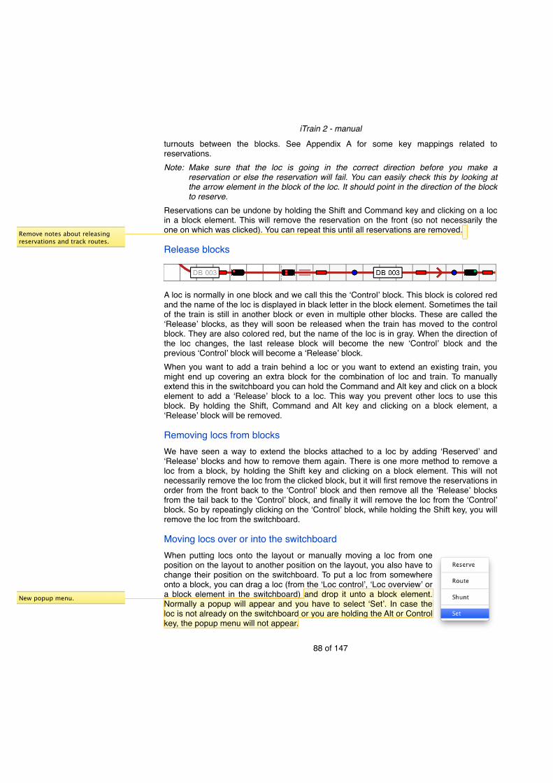
turnouts between the blocks. See Appendix A for some key mappings related to reservations.Note:! Make sure that the loc is going in the correct direction before you make a
reservation or else the reservation will fail. You can easily check this by looking at the arrow element in the block of the loc. It should point in the direction of the block to reserve.
Reservations can be undone by holding the Shift and Command key and clicking on a loc in a block element. This will remove the reservation on the front (so not necessarily the one on which was clicked). You can repeat this until all reservations are removed.
Release blocks
A loc is normally in one block and we call this the ʻControlʼ block. This block is colored red and the name of the loc is displayed in black letter in the block element. Sometimes the tail of the train is still in another block or even in multiple other blocks. These are called the ʻReleaseʼ blocks, as they will soon be released when the train has moved to the control block. They are also colored red, but the name of the loc is in gray. When the direction of the loc changes, the last release block will become the new ʻControlʼ block and the previous ʻControlʼ block will become a ʻReleaseʼ block.When you want to add a train behind a loc or you want to extend an existing train, you might end up covering an extra block for the combination of loc and train. To manually extend this in the switchboard you can hold the Command and Alt key and click on a block element to add a ʻReleaseʼ block to a loc. This way you prevent other locs to use this block. By holding the Shift, Command and Alt key and clicking on a block element, a ʻReleaseʼ block will be removed.
Removing locs from blocksWe have seen a way to extend the blocks attached to a loc by adding ʻReservedʼ and ʻReleaseʼ blocks and how to remove them again. There is one more method to remove a loc from a block, by holding the Shift key and clicking on a block element. This will not necessarily remove the loc from the clicked block, but it will first remove the reservations in order from the front back to the ʻControlʼ block and then remove all the ʻReleaseʼ blocks from the tail back to the ʻControlʼ block, and finally it will remove the loc from the ʻControlʼ block. So by repeatingly clicking on the ʻControlʼ block, while holding the Shift key, you will remove the loc from the switchboard.
Moving locs over or into the switchboardWhen putting locs onto the layout or manually moving a loc from one position on the layout to another position on the layout, you also have to change their position on the switchboard. To put a loc from somewhere onto a block, you can drag a loc (from the ʻLoc controlʼ, ʻLoc overviewʼ or a block element in the switchboard) and drop it unto a block element. Normally a popup will appear and you have to select ʻSetʼ. In case the loc is not already on the switchboard or you are holding the Alt or Control key, the popup menu will not appear.
iTrain 2 - manual
88 of 147
Remove notes about releasing reservations and track routes.
New popup menu.

Context popup menuSome of the release actions for reserved and release blocks can also be reached via a context sensitive popup menu of the block element, without using the modifier keys. This popup menu can be shown by pressing the (left) mouse button on the block and waiting until it appears.
ʻHead of reservationsʼ means that all reserved blocks beyond this block will be released and this block becomes the head. The same can be achieved without a popup menu by holding the Shift and Command key and double clicking on a block.ʻTail of releasesʼ means that all release blocks behind this block will be released and this block becomes the tail. The same can be achieved without a popup menu by holding the Shift, Alt and Command key and double clicking on a block.In case there are no release blocks, but there are still reserved turnouts or other accessories that are part of the track route, the option ʻRelease track routeʼ will be available to release the track route. Only use this if you are sure that no part of the train is occupying (parts of) the reserved turnout. The same can be achieved without a popup menu by holding the Shift and Alt key and clicking on the block. Tip:! The popup menu items are spaced so that you can easily choose the correct item
with your finger on a touchscreen.
iTrain 2 - manual
89 of 147
New section
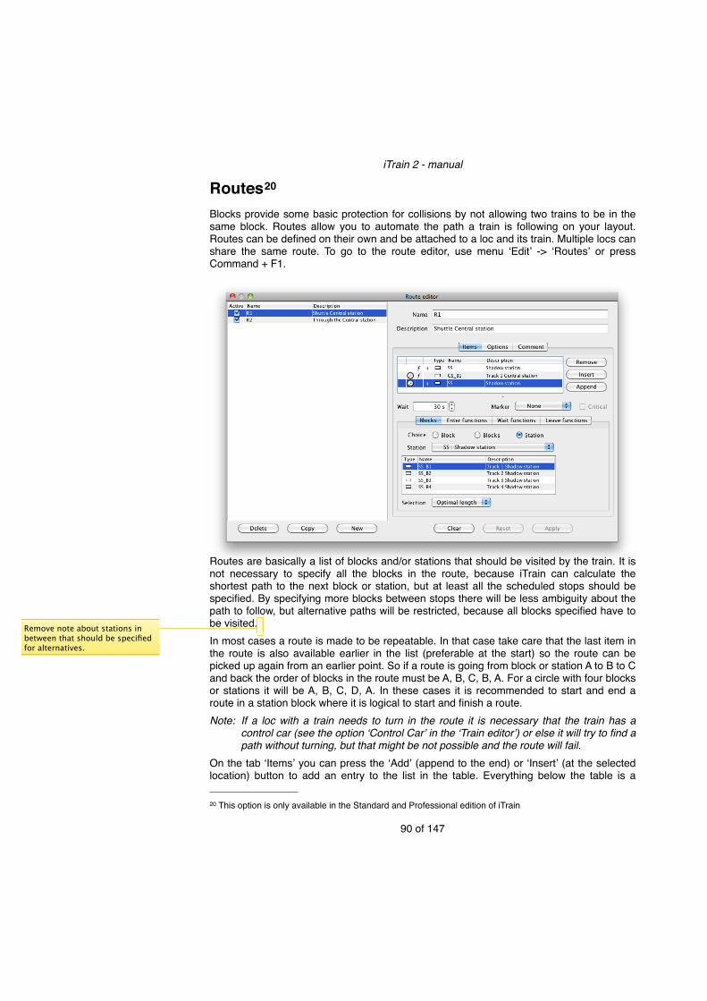
Routes20
Blocks provide some basic protection for collisions by not allowing two trains to be in the same block. Routes allow you to automate the path a train is following on your layout. Routes can be defined on their own and be attached to a loc and its train. Multiple locs can share the same route. To go to the route editor, use menu ʻEditʼ -> ʻRoutesʼ or press Command + F1.
Routes are basically a list of blocks and/or stations that should be visited by the train. It is not necessary to specify all the blocks in the route, because iTrain can calculate the shortest path to the next block or station, but at least all the scheduled stops should be specified. By specifying more blocks between stops there will be less ambiguity about the path to follow, but alternative paths will be restricted, because all blocks specified have to be visited.In most cases a route is made to be repeatable. In that case take care that the last item in the route is also available earlier in the list (preferable at the start) so the route can be picked up again from an earlier point. So if a route is going from block or station A to B to C and back the order of blocks in the route must be A, B, C, B, A. For a circle with four blocks or stations it will be A, B, C, D, A. In these cases it is recommended to start and end a route in a station block where it is logical to start and finish a route.Note:! If a loc with a train needs to turn in the route it is necessary that the train has a
control car (see the option ʻControl Carʼ in the ʻTrain editorʼ) or else it will try to find a path without turning, but that might be not possible and the route will fail.
On the tab ̒ Itemsʼ you can press the ʻAddʼ (append to the end) or ʻInsertʼ (at the selected location) button to add an entry to the list in the table. Everything below the table is a
iTrain 2 - manual
90 of 147
20 This option is only available in the Standard and Professional edition of iTrain
Remove note about stations in between that should be specified for alternatives.
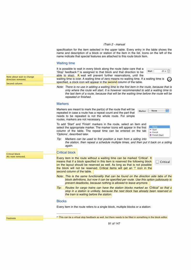
specification for the item selected in the upper table. Every entry in the table shows the name and description of a block or station of the item in the list. Icons on the left of the name indicate that special features are attached to this route block item.
Waiting timeIt is possible to wait in every block along the route (take care that a ʻStopʼ feedback 21 is assigned to that block and that direction to be able to stop). A wait will prevent further reservations, until the waiting time is over. A waiting time of zero means no waiting time. If a waiting time is specified, a clock icon will appear in the second column of the table.Note:! There is no use in adding a waiting time to the first item in the route, because that is
only where the route will start. It is however recommended to add a waiting time to the last item of a route, because that will be the waiting time before the route will be repeated or finished.
MarkersMarkers are meant to mark the part(s) of the route that will be repeated in case a route has a repeat count and the part that needs to be repeated is not the whole route. For simple routes, markers are not necessary.To add ʻStartʼ and ʻFinishʼ markers in the route, select an item and select the appropriate marker. The marker icons will appear in the first column of the table. The repeat time can be entered on the tab ʻOptionsʼ, described later.Tip:! Markers can be used to first position a train from a siding into
the station, then repeat a schedule multiple times, and then put it back on a siding again.
Critical blockEvery item in the route without a waiting time can be marked ʻCriticalʼ. It means that if a block specified in this item is reserved the following block on the layout should be reserved as well. As long as that is not possible the block will not be reserved. Critical items will get an ʻ!ʼ icon in the second column of the table.Note:! This is the same functionality that can be found on the direction side tabs of the
block definitions, but now it can be specified per route. Use this option judiciously to prevent deadlocks, because nothing is allowed to leave anymore.
Tip:! Routes for cargo trains can have the station blocks marked as ʻCriticalʼ so that a stop in a station is unlikely, because the next block has already been reserved or the train is waiting before the station.
BlocksEvery item in the route refers to a single block, multiple blocks or a station:
iTrain 2 - manual
91 of 147
21 This can be a virtual stop feedback as well, but there needs to be filled in something in the block editor.
Note about wait to change direction removed.
Critical blockAls note removed.
Footnote
Second column

• Block - You only have to select the block.
• Blocks - You can make a list of blocks (comparable with the old alternative blocks). Normally these blocks are parallel blocks, but it is not limited to that. It is allowed to take two blocks in different locations to generate some random behavior.
• Station - You have to select a station that is defined as a list of blocks. Automatically the list of blocks currently attached to this station will be shown, but the list is not editable here and not stored with the route itself. When the station definition changes the route will use the new list of blocks.
The last two choices make the route more dynamic, because a block from a list will be chosen. This is indicated by a ʻ+ʼ icon in the fourth column of the item table. Which block will be chosen is based on the box ʻSelectionʼ. The options are:• ʻIn orderʼ means the first block in the list will be chosen, unless
this one is already occupied, then the next will be tried and so on.
• ʻAt randomʼ means that the list is shuffled at random and then the first block will be chosen, unless this one is already occupied, then the next will be tried and so on.
• ʻOptimal lengthʼ means all the block in the list are sorted in the order of their length from short to long, and blocks that are too short for this train are removed. Now the first block will be chosen, unless this one is already occupied, then the next will be tried and so on.
iTrain 2 - manual
92 of 147
New fourth column

This option is to prevent short trains from occupying a long block in a station so that a next longer train cannot enter it anymore, because only short blocks are left over. It is useful for shadow stations.
• Shortest path means all the blocks in the list are sorted in the order of their path length to reach them. Now the first block will be chosen, unless this one is already occupied, then the next will be tried and so on. This is only useful if not all intermediate blocks in the route are specified.
• ʻFirst allowedʼ always takes the first block in the list (even if it is occupied) unless the block or something in the path to this block is disabled or not allowed (specified via the permissions tab of the loc or train), then it will take the next and so on. It is useful for fixed routes that are only adapted when some blocks are inactive or another loc or train with different permissions is used.
Note:! An electrical loc is never allowed to use a block without catenary.
FunctionsIt is possible to control loc functions in a route when entering a block, waiting in a block, or leaving a block after a stop. Three additional tabs allow you to enter them.
To add loc functions on a tab use the ʻAddʼ or ʻInsertʼ button to add a new function. Select in the first column one of the loc functions and in the second column the new state of the loc function. The state ʻToggleʼ is to change the current state so that if it is ʻonʼ it will go to ʻoffʼ and vice versa. The state ʻPulseʼ is meant for setting the state to ʻonʼ and then after a short time switching it to ʻoffʼ again. This is useful for momentary functions like horn, whistle or bell. The third column specifies the duration of the function and is normally used for state ʻPulseʼ, so it will be switched off after the duration. It can however also be used for other states to indicate how long the action in the loc would take, for example the time it takes to raise or lower the pantograph.The fourth column ʻDelayʼ specifies the delay time before the function will be switched. Functions are always switched after each other so the delay is relative to the previous function. This way you can build a whole sequence of functions that are executed after each other.Note:! The ʻLeave functionsʼ are activated before the loc starts. That is the reason you can
specify a duration for each function in case it will take some time to execute it in the loc, so the program can compute when all the functions have been finished before starting the loc.
iTrain 2 - manual
93 of 147
New shortest path

Note:! The ʻLeave functionsʼ will not be used when the loc moves through the block without waiting. Use the ʻEnter functionsʼ of the next block instead.
If functions are attached to a block in a route, a function icon will appear in the third column of the table.
OptionsThe route also has some settings that act on the whole route:
• The ʻRepeatʼ count is the number of times that a route is being completely followed by a train before the route is stopped. A zero means the route is being repeated forever until the route is manually ended. If you have defined markers, then only the section between the start and end marker will be repeated.
• The ʻReservation countʼ is the number of blocks a route tries to reserve in front of the current block of the train. This is not a guarantee, but a best effort. It will however never try to reserve past a block with waiting time specified in the route until the loc is stopped and the waiting time has passed. In some cases it may reserve more blocks if the train cannot stop in the last reserved block or if it is critical.
• The ʻReserved startʼ is the number of blocks that must have been reserved before the loc actually starts to depart after the ʻWaiting timeʼ has passed or when the route has been activated. This is to prevent multiple waits for a signal of a loc in a free block while it could have been waiting in the station. It does not have effect on the reservations or the signals either, but it only affects the departure time of the waiting train.
• The option ʻDirection changeʼ specifies if the direction of the loc may be changed while executing the route. The third option ʻDependent on trainʼ will only allow locs without a train or locs with a train with a control car to change the direction. This last option is the default setting.
• If the option ʻSet turnouts alwaysʼ is selected it is guaranteed that all the turnouts will be activated by the interface, even when the program thinks they are already in the correct state. This costs more switching time, but prevents errors by manual changes outside the program.
iTrain 2 - manual
94 of 147
Only when waiting time is specified not when it is inserted automatically for a direction change.
New direction change
Third column
Extra line explaining.
Rewritten
Critical
New extra

Route controlRoutes can be attached to a loc and its train in the ʻTrainʼ tab of the ʻLoc controlʼ. This associates one or more locs with a specific route without activating the route at that moment.
Routes can be controlled in the ʻLoc controlʼ and the ʻLoc overviewʼ via the buttons ʻStartʼ and ʻStopʼ , their popup menu or a key combination.
In the switchboard, routes can be controlled via the context sensitive popup menu of a block element that contains a loc. You have to press the (left) mouse button on the block element and hold it until the popup menu appears.There are three commands:• ʻStartʼ - to activate the route. A route can only be started if the loc is in one of the blocks
along the route and will start at that position in the route. In case of multiple occurrences of the current block of a loc in the route it will start at the first occurrence of the block in which the loc will drive in the same direction as it is now. The key combination is Shift + F5.
• ʻStopʼ - to stop and deactivate a route immediately. The loc will stop (not halt abruptly) at its current location. The key combination is Shift + F6.
• ʻFinishʼ - to first visit all the remaining blocks of the route and stop after the loc has arrived in the last block without any repeats. The key combination is Shift + F7. You can also select this by holding ʻShiftʼ and clicking the Stop button. Now the button will
show meaning it is still running, but will not be repeated anymore.
iTrain 2 - manual
95 of 147
‘along’ instead of ‘of’
New Popup menu to start routes

Info
Information about the route will be displayed on the ʻLoc Controlʼ below the the image after ʻInfoʼ and can be added as an extra column ʻInfoʼ in the ʻLoc overviewʼ.
It will show a message why a route failed, what it is doing or an arrow followed by the next possible destinations to stop. The list of destinations will be reduced over time until one has been chosen.Scheduled stop
Blocks reserved by a loc in which it will have a scheduled stop (waiting time > 0) will show a yellow bar behind the loc name in gray. After stopping in that block the yellow bar will shrink with time until the waiting time is over. Now the route can be continued and reservations will be made again.
In the route info box, the same yellow bar will appear, but instead of the loc name the time left will be shown.
Instant routeCreating a route takes some effort, but you will have full control of all the options and you can use the route multiple times. Sometimes you only want a simple route from A to B without options, and execute it only once. This can be achieved by dragging a loc to its destination. After dropping the loc on the destination a popup appears. Four options will appear in which the second and third choice will create an instant route, but all are described here for completeness:• Reserve - a full path will be created to the destination without direction
changes. You have to drive the train manually or change the control type to ʻAutomaticʼ.
• Route - a simple, temporary route will be created to the destination, only allowing direction changes if there is no train attached to the loc or
iTrain 2 - manual
96 of 147
Section name
New instant route
New box for info with time left.
the train has a control car.• Shunt - a simple, temporary route will be created to the destination, allowing direction
changes. Normally used to shunt trains from a side track to a station track or back again. Multiple direction changes are allowed, even without a control car.
• Set - just inform iTrain that the loc is now set in a block by putting it unto the track yourself.
To use ʻInstant routeʼ, select ʻRouteʼ or ʻShuntʼ and the route will be executed immediately. It will give ʻInfoʼ just like a normal route, but when the route has finished or the ʻStopʼ button is used, the temporary route is removed and you cannot continue. You have to create a new one again. The route originally attached to the loc will remain there, and pressing ʻStartʼ will start this route again. Tip:! You can use ʻInstant routeʼ to put a loc in a position prior to starting the route
attached to the loc.
iTrain 2 - manual
97 of 147

EditorsNext to the locomotives, trains, routes and switchboard editor, you can also edit the accessories, feedbacks, track routes, blocks and stations directly via the ʻEditʼ menu without going to the switchboard first. This is useful to quickly change a definition or to manage the list of objects.
A dialog will appear with at the left side a list with the objects of a type (accessories, feedbacks, track routes, etc.) known by iTrain. To manage the list of objects you use the buttons below the list. You can add a new object by using the ʻNewʼ or ʻCopyʼ button. In case of ʻCopyʼ the currently selected object is used as a template and its definitions are copied to the new one. Only the name is adapted to create a unique name. The ʻDeleteʼ button removes the currently selected object from the list.Note:! The ʻDeleteʼ button really deletes the control object and it will remove all references
to this object from other control objects. Only delete an object if you are sure it is not used or referenced elsewhere or it could give unexpected results. Never delete a control object and create a new one, because you want to change the name or address.
On the right side you find the specific object editor to change all object definitions. You have to fill in at least a name and in many cases an address. The buttons below the editor give some extra control over the editor:• The ʻApplyʼ button applies changes you made in the input fields. This will immediately be
reflected in all windows. If you select another object the previously selected object will automatically be applied.
• The ʻResetʼ button discards the changes you made in the editor and reloads the fields with the current value. After an ʻApplyʼ a reset will only discard changes made after the ʻApplyʼ.
iTrain 2 - manual
98 of 147
Add stations

• The ʻClearʼ button clears all the fields.
AccessoriesIn case of the accessories editor, six tabs are available on the right side with on each tab its own object editor. If you select an existing accessory in the list, the correct tab will be selected and the others will be grayed out. If you want to add a new accessory you have two options: • Use the ʻNewʼ button. All tabs are available and you should first select the correct one
(Turnout, Signal, Relay, Decoupler, Turntable or Transfer table) and then fill in the fields. Fields in other tabs are discarded after using ʻApplyʼ.
• Use the ʻCopyʼ button to create a new accessory based on an existing accessory. In this case the type cannot be changed anymore, because the other tabs are grayed out.
Blocks/StationsIn case of the block or station editor, it is not possible to use the ʻAuto fillʼ button or ʻCreate connectionsʼ popup menu now, because it is now not related to the switchboard where the information is coming from. This is only possible if you are in the switchboard editor and select a block element.
iTrain 2 - manual
99 of 147
Block or station
Blocks or stations

Extra toolsThe extra tools are available via the ʻViewʼ menu.
KeyboardThe keyboard is an address based control tool for changing accessories like turnouts, signals, decouplers and relays. A keyboard is available for every interface in the project that supports pulse based accessories22. Every address has two buttons, ʻredʼ and ʻgreenʼ. When the button is filled, it is connected with an accessory object in the program. The highlighted buttons represent the state the accessory is in. Open buttons are not related to accessory objects in the program, but can still be activated for example to program a new signal.
A popup menu (right mouse click or Control key + click) allows you to increase/decrease the number of modules (also with ʻ=ʼ and ʻ-ʼ keys) or to toggle between ʻGroupingʼ and absolute address mode (also the ʻAʼ key).
The keyboard automatically scales to fit the width of the window. By using the ʻFʼ key you fit the dialog window height to the current size of the keyboard.Note:! Using the same address for two or more accessories is allowed in iTrain so they will
all be switched when the state of one of them is changed. In some cases using the
iTrain 2 - manual
100 of 147
22 The OM32 and OC32 have a mode for direct pulse based accessories, but the keyboard is only available for accessories switched via a connected ʻDecoder63ʼ.
Keyboard only for Decoder63

same address might indicate an error. Therefore addresses that are used more than once have a white border around the button to indicate this is a special case and you have to check if this is okay.
Feedback MonitorThe feedback monitor is an address based monitor tool for showing feedback states. A feedback monitor is available for every interface in the project that supports feedbacks. Every button represents one feedback contact. If the button is filled it is connected with a feedback object in the program. A blue button means the feedback is activated. Open buttons are not related to feedback objects in the program, but still show the state they have received from the interface.
A popup menu (right mouse click or Control key + click) allows you to increase/decrease the number of modules (also with ʻ=ʼ and ʻ-ʼ keys) or to toggle between ʻGroupingʼ and absolute address mode (also the ʻAʼ key).
The feedback monitor automatically scales to fit the width of the window. By using the ʻFʼ key you fit the dialog window height to the current size of the feedback monitor.Note:! Using the same address for two or more feedbacks normally indicates
an error situation, and the button will have a red border/edge. In case feedbacks share an address because they have been connected via a relay (so that only one is actually wired at the same time), the button will have a yellow border/edge.
S88 Address numberingDepending on the feedback system you use the addresses are fixed and configured per feedback decoder (for example LocoNet®) or in case of the widely used S88 system the addresses are assigned based on the location of the feedback module in the string of
iTrain 2 - manual
101 of 147

modules connected to the S88 bus. So adding or removing a module in the string will change the addresses of all feedbacks connected to modules later in the string.
The menu ʻEdit module wiringʼ in the popup menu of the feedback monitor has two menu items to add and remove a module so that all addresses of the following feedbacks will be shifted up or down automatically.
A dialog will appear to select the first address of the module to be inserted or removed and the number of addresses to be inserted or removed (ʻAddress countʼ). The result can be seen in the feedback monitor immediately after pressing the ʻOKʼ button.
Extra23
The menu ʻViewʼ -> ʻExtraʼ allows you to add a copy of the ʻLoc overviewʼ, ʻLoc gridʼ or the ʻSwitchboardʼ in a separate window. You can put the extra views on a second monitor. In case of the switchboard it shows the same layout and object states, but it allows you to view another tab at the same time or the same tab with another zoom level. This will be useful if you are controlling a large layout that doesnʼt fit on one screen.
iTrain 2 - manual
102 of 147
23 This option is only available in the Professional edition of iTrain.

Network24
By default iTrain runs in stand-alone mode, but it is also possible to run iTrain in a network. In that case you can start iTrain multiple times on different computers and control the layout with multiple people or at different sides of the layout. In a network, one iTrain program is the server and it directly controls the layout. The other iTrain programs are the clients and they communicate via the server with the layout over your local network.
Server mode
To start a network you first have to start one iTrain installation (the one that is connected to the layout) and in the preferences go to ʻNetworkʼ. Change the ʻModeʼ to ʻServerʼ (leave the port to 7120 unless it conflicts with another service already running on that port). iTrain is now in server mode and will wait for incoming connections from other iTrain programs in ʻClientʼ mode. This setting will be remembered so that next time you start this iTrain it will immediately be a ʻServerʼ until you change the mode to ʻStand aloneʼ.The fact that iTrain is in ʻServerʼ mode can also be seen on the status bar where an icon followed by the text ʻClients: 0ʼ appears. By hovering over this item in the status bar, a tooltip will appear with the name and IP address of the server. If the computer has multiple network interfaces such as a wired ʻEthernetʼ port, a wireless network (WiFi), etc. it is possible that two or more IP addresses will show up.
iTrain 2 - manual
103 of 147
24 Networking is only available in the Professional edition of iTrain.

Client mode25
Now that one instance of iTrain is running in ʻServerʼ mode you can start other iTrain programs on other computers, but they will by default start in ʻStand aloneʼ mode. Via the same preferences and the tab ̒ Networkʼ, now select ʻClientʼ mode and after the IP address fill in the IP address (or the name if this is known by the ʻClientʼ computer) of the iTrain server. You have to close this iTrain program and restart it to run it in ʻClientʼ mode and it will automatically try to connect to the server when it is started again. If it cannot connect to the server you will get an error message and it will start in ʻStand aloneʼ mode again, but it will try to start in ʻClientʼ mode again the next time you startup until you change the mode to ʻStand aloneʼ again.In ʻClientʼ mode there are some restrictions:• You cannot open and save files, because this is controlled by the server.• You cannot change the interface or control its parameters, because this is the job of the
server.• You cannot edit the switchboard in ʻClientʼ mode. Changes on the server will be sent to
the client immediately.• New objects like a new locomotive must be added by the server, but changes in the
definition like the name or address can be done on the client side.When closing the server, all clients will automatically be informed and it is not useful to continue working with iTrain in ʻClientʼ mode. A client however, can quit at any time without affecting the server.
iTrain 2 - manual
104 of 147
25 It is possible to use the Standard edition in client mode so that when a club has the Professional edition and members have the Standard edition, they can bring their notebook to join the network. This cannot be done via the preferences. The club has to contact us to ask how this can be done.

iOS26
You can use iOS devices such as an iPhone, iPad or iPod touch with an appropriate App as a client and connect them to iTrain in server mode. In this case it is important to set up the network settings correctly. After installing the App you have to go to the general ʻSettingsʼ on the device and select the App.
Below the ʻServerʼ you have to fill in the IP address of the server before you can start the App.
StatusOn the server you can monitor all the connected clients via the status bar. You will see the number of connected clients immediately and by double-clicking on it a new dialog will appear with a list of all network clients.
In the title of the dialog you see the name and the IP address(es) of the server and the number of clients connected. Every connected client has a row in the table with its name, IP address, the version of the client, the operating system, the programming language and the time the connection started. By clicking on the red icon before the name you can disconnect individual clients.In a tooltip per row you can find more details, like the port used on the client and the local or server address (and port) to which the client has been connected.Note:! iTrain has been designed in such a way that using more
than one client does not add much extra overhead (just one thread) for the server. Only at the start of a connection a lot of data will be exchanged to inform the client of the current status of all objects and the layout. Afterwards the clients are only informed about the changes.
iTrain 2 - manual
105 of 147
26 iOS clients might not be officially available at this time of writing, but prototypes are already available.
New tooltip
Other columns

Appendix A: Defined keysA modifier key like Shift, Control, Alt and Command is used by holding this key down while pressing another key at the same time.We use the following abbreviations:Shift - for the Shift keyCtrl - for the Control keyAlt - for the Alt keyCmd - for the Command key (on Windows, Linux and Solaris this should also be read as Control key).
Globally defined keys
Key Action
Escape Stop: Takes power off the tracks, all locs will stop (use F5 to continue)
F1 Reserved for Help (no online help available at this time)
F2 Focus on loc overview
F3 Focus on loc panel
F4 Focus on switchboard
F5 Go: Put power on tracks again and locs will continue
F6 Toggle between going online/offline
Cmd + F1 Edit Routes
Cmd + F2 Edit Locomotives
Cmd + F3 Edit Trains
Cmd + F4 Edit Switchboard
Shift + Cmd + F1 Edit Accessories
Shift + Cmd + F2 Edit Feedbacks
Shift + Cmd + F3 Edit Track Routes
Shift + Cmd + F4 Edit Blocks
Cmd + O Open File
Cmd + S Save File
Shift + Cmd + S Save File as ...
iTrain 2 - manual
106 of 147

Key Action
Cmd + P Print Switchboard
Loc keysThese keys will be available when the ̒ Loc overviewʼ or the ʻLoc controlʼ has focus. To give the ʻLoc overviewʼ focus, press F2 and to give the ʻLoc controlʼ focus, press F3. Every time you press F3 again another ʻLoc controlʼ gets the focus.
Key Action
H Halt or emergency stop
0 Brake to speed zero and stop.
1-9 Set speed in steps of 10 km/h (3 = 30 km/h).
Shift + 0-9 Set speed in steps of 10 km/h starting at 100 km/h (Shift + 4 = 140 km/h).
- Decrease speed to the previous step of 5 km/h below the current speed (starting at 72 km/h it will be 70, 65, 60).
+ Increase speed to the next step of 5 km/h above the current speed (starting at 72 km/h it will be 75, 80, 85).
Backspace Brake to speed zero and stop when driving, and when stopped, change the direction (so 0 or D depending on current speed).
D Change the direction of the loc.
A Change to automatic control. A loc may start to drive if allowed.
S Change to semi-automatic control.
M Change to manual control.
Delete Remove a block from a loc. At first a reserved block is removed (at the front), then a release block (from the end) and finally the current control block.
Shift + F5 Start a route for a loc (when a route is attached).
Shift + F6 Stop a route and/or stop the loc.
Shift + F7 Finish the route, but do no repeat it anymore.
L Normal front lights
Shift + L Normal rear lights
V Head lights (first available so including the front).
iTrain 2 - manual
107 of 147

Key Action
Shift +V Head lights on the rear side.
C Cabin light (first available so including the front).
Shift + C Cabin light on the rear side.
I Interior light
W Driving wheel light
Shift + W Engine light
B Sound of bell
F Whistle
N Signal horn
E Engine sound
Shift + E Blow out cylinder
G Generator
Shift + G Relay steps
Z Fan
Shift + Z Pump
J Compressed air
Shift + J Brake sound
Q Buffer impact
Shift + Q Couplers engaging
X Door (first available so including Door opening)
Shift + X Door closing
U Announcement (first available so including Station announcement)
Shift + U Train announcement
K Coal shoveling
Shift + K Grate being shaken
O Smoke
R Direct control (no acceleration/deceleration).
iTrain 2 - manual
108 of 147
Direct control instead of shunt

Key Action
Shift + R Slow (decoder steps are related to lower speeds).
T Telex coupling (first available so including the front).
Shift + T Telex coupling on the rear side.
P Pantograph (first available so including the front).
Shift + P Pantograph on the rear side.
The numeric key pad can also be used to control locs. The ʻ-ʼ and ʻ+ʼ and the 0-9 keys behave the same as on the main keyboard. Extra functionality only available on the numeric pad is summarized below:
Key Action
. or , Change the direction of the loc.
* Reserve the next block for a locomotive.
/ Remove the most recent reservation on the front.
Shift + * Add a ʻReleaseʼ block to the back of a loc.
Shift + / Remove the last ʻReleaseʼ block on the back of a loc.
Tip:! Some of the keys attached to a loc can also be used globally (without focus) when used in combination with the Alt key. In this case, the loc selected in the ʻLoc overviewʼ is controlled. It concerns the ʻ-ʼ, ʻ+ʼ, ʻ*ʼ, ʻ/ʼ and Backspace key.
In case of the ʻLoc controlʼ, there are some specific keys for use with the Loc Grid:
Key Action
Alt + Cursor keys Change the size of the loc grid. Left and Up to decrease the size and Down and Right to increase the size.
Alt + F3 Fill the ʻLoc controlsʼ with the available locs.
In case of the ʻLoc overviewʼ there is one specific key:
Key Action
Enter To put the currently selected loc in the overview, in the (first) ʻLoc controlʼ.
Switchboard control keysThese keys will be available when the switchboard has focus. To give the switchboard focus, press F4.
iTrain 2 - manual
109 of 147

Key Action
Cmd + G Toggle between show grid and hide grid.
Cmd + B Fit switchboard on both width and height.
Cmd + W Fit switchboard on width of the switchboard.
Cmd + E Fit switchboard on height of the switchboard.
Keys that are defined and attached to switchboard elements can also be used here. It is better not to use the globally defined keys or the switchboard keys for this.
Switchboard edit keysThe following keys are can be used when editing the switchboard (Cmd + F4):
Key Action
Cmd + B Fit switchboard on both width and height.
Cmd + W Fit switchboard on width of the switchboard.
Cmd + E Fit switchboard on height of the switchboard.
Cmd + cursor keys Select or turn the elements on the element toolbar on the right.
Cmd + T Turn the selected element on the element toolbar clockwise.
Cmd + R Turn the selected element on the element toolbar counter-clockwise.
Cmd + Enter Select the object in the object browser that is attached to the selected element in the switchboard.
Alt + cursor keys Change the size of the grid.
Shift + cursor keys Select multiple cells.
Shift + Alt + cursor keys
Change the size of a resizable element on the grid.
Shift + Cmd + cursor keys
Move the selected elements over the switchboard.
Space Put the selected element on the element toolbar on the switchboard.
Enter Edit properties of the selected element in the switchboard.
T Turn the selected element on the switchboard clockwise (only for single cell selection).
iTrain 2 - manual
110 of 147

Key Action
R Turn the selected element on the switchboard counter-clockwise (only for single cell selection).
Shift + R / Shift + T Turn the selected elements 180 degrees.
O Toggle between showing and hiding the object browser.
P Pack or trim the switchboard so that empty cells at the borders are removed.
Delete or Backspace
Delete an element on top (single cell selection) or delete all selected elements.
Shift + Delete or Backspace
Delete an element below (single cell selection) or delete all selected elements.
B Assign an element to a block or, if no block has yet been selected, select a block.
Shift + B Remove an element from the selected block.
Cmd + Z Undo the most recent remove, cut or move operation (only works before a selection change).
Cmd + X Cut the selection. Delete the selected elements and put them on the clipboard.
Cmd + C Copy the selection. Put the selected elements on the clipboard.
Cmd + V Paste from clipboard. Put the elements on the clipboard on the switchboard (and widen the grid if necessary).
L Select the Straight line from the element toolbar on the right.
C Select the Curve line from the element toolbar on the right.
Shift + E Assign a Text element to the selected cells in the switchboard.
Shift + P Assign a Platform element to the selected cells in the switchboard.
Shift + S Assign a Station element to the selected cells in the switchboard.
Shift + H Assign a Building or House element to the selected cells in the switchboard.
Shift + I Assign an Image element to the selected cells in the switchboard.
Alt + R Rename a tab
Alt + I Insert a tab at the current position
Alt + ʻ+ʼ Add/append a tab at the end
iTrain 2 - manual
111 of 147

Key Action
Alt + ʻ-ʼ Remove the current tab
Alt + Page up Go to the next tab
Alt + Page down Go to the previous tab
Tip:! In general, the Command or Control key in combination with a normal key, affects the element toolbar on the right. The Alt key combined with cursor keys is for sizing. The Shift key is associated with selections or cells that are resizable.
All tool windowsFor tool/floating windows with for example a loc grid, switchboard or keyboard, the following keys are defined:
Key Action
Alt + F To fit the window size to the preferred size of the contents.
iTrain 2 - manual
112 of 147

Appendix B: FeedbacksFeedbacks are very important in computer control. They are the eyes or sensors that feed the computer with information on what is happening on the layout. For a program like iTrain, very sophisticated feedbacks are not necessary. Only an ʻonʼ or ʻoffʼ or ʻ1ʼ or ʻ0ʼ is enough. We call these binary sensors. They detect if something is pressed or not, something is occupied or not, or something is passed or not. The ʻsomethingʼ will be determined by the logic in iTrain.We can distinguish two types of feedbacks:1. Occupancy - they inform the system if (part of) a track is occupied.2. Momentary - they inform the system that an event happened, for example that (part of)
a train was passing.
OccupancyAn occupancy sensor or feedback has the advantage that it can be read out any moment to tell if (part of) a track is occupied. No train movements are necessary. I recommend this type of feedback over momentary feedbacks when used in association with blocks.To create an occupancy feedback, it is generally necessary to isolate one rail of a track. This can be done by using plastic connections or plastic isolators or by cutting a rail. The isolated part should have a wire that can be connected to a device or decoder that can read feedbacks outputs. Depending on the rail type, there are two methods:• 3-rail (Märklin HO) - the isolated rail is normally connected to ground and can be
attached to any feedback decoder based on ground detection (for example S88). An occupancy detector works the same as a ʻcontact railʼ.
• 2-rail (others) - the isolated rail still needs to feed the track with power, so that locs will run, so the isolated rail is connected via a current detection system to the normal power and the current detection system is connected to a feedback decoder. In many cases, both devices are combined into one. Only locs and wagons with light or other power consuming devices are detectable.
MomentaryMomentary contacts just give a short pulse when something is activating them. An example is a reed contact that is activated when a magnet is above it. This can be used to detect a train by attaching a reed contact between the rails in the track and putting a magnet below a loc or other part of a train. This method is not appropriate for smaller tracks scales like N and Z.
iTrain supports both types of feedbacks, but I personally prefer occupancy feedbacks over momentary feedbacks to detect trains in blocks. The choice you make will depend on your requirements, your scale and track and your investigation of costs and benefits. Be informed by what is available in the market and look up the web for more information.
iTrain 2 - manual
113 of 147

Appendix C: iTrain user forumThe iTrain user forum is there to inform you about and give you support on iTrain. It is available at http://berros.eu/itrain/forum/ via a web browser. It is not an open forum and only registered users can read it. You have to register with a self chosen username and password. Your registration will be verified by the webmaster so you have to choose a decent username or it might be refused.Initially it will start in English, but you can set the language and timezone you prefer.
The iTrain forum has been divided into different sections each containing a sub-forum for a specific language. Each sub-forum contains the same division so you can read and ask questions in your preferred language by choosing the right sub forum.
The first section ʻAnnouncementsʼ is a section to keep you up to date with the latest information about iTrain, such as releases and trade fairs. You cannot start an announcement, but only react on it. The same holds for the second section ʻFrequently Asked Questionsʼ.
iTrain 2 - manual
114 of 147
New section

The third section ʻSupportʼ is really for support questions. Here you can ask your own questions or respond to others. First choose the right category. Then use ʻNewTopicʼ to add a new topic.
Always choose a good subject so your question can be found easily by other users. Also provide the information that is necessary for someone else to help you. In many cases this involves adding your own layout so people can see what you have been doing. The layout must first be saved in iTrain as a zip-file by ending the filename with .zip and then you can add it to the forum via the second tab ʻUpload attachmentʼ.
Try to formulate your question well and read it again before you submit it. Well formulated questions are answered more quickly, because there is less need for additional questions that will take more time. For additional questions not related to the current subject you should create a new topic and not continue the current thread. The questions also function as a database for new users in which they can find answers and the better the subject names are and the shorter and more to the point the topic is, the easier it is to find.The last section ʻEnhancement requestʼ is for more experienced users who know what is possible in iTrain, but still lack some functionality or have some suggestions how to improve it. There is no guarantee that your suggestion will be included in iTrain within a certain time-frame, but all will be read and if possible discussed to get clear how it should be changed. The best ones will be considered to be implemented in the next or a later release.In some cases you would like to exchange some details with another user that should not be visible to others. In that case send a PM (=Private message) to another user. Never put your address, phone or e-mail address in a topic if you want contact with other users. Just ask for contact and interested people can respond with a PM to exchange contact details.Please be polite, patient and forgiving to other members both in asking and answering. We want to welcome new members, but also appreciate members who are spending a lot of time answering your questions and building this iTrain community. In case something happens that is not correct or really annoys you, please send an e-mail to [email protected] so we can intervene or solve it.
iTrain 2 - manual
115 of 147

Appendix D: Interface specificsNext to the general settings, every interface has specific settings on the last tab of the ʻInterface Editorʼ. Some interfaces may have an empty page. If the control of the interface has been restricted by changing the checks for ʻControl typeʼ, then some options may not be visible, because they do not apply in this case.
DemoThe ʻDemoʼ interface is a dummy interface to be used for testing when you have no command station. It will treat every decoder as if it were connected to a system that supports all its possibilities. For example, an MFX decoder will have all steps and all functions are supported.
Märklin 6051This is an interface protocol supported by many older systems and known as the P50 protocol. It was originally designed for the Märklin Interface 6050/6051 that can be used with the Märklin Control Unit 6021.In some case it is necessary to specify a minimum time between sending two commands in case the flow control is not optimal and some messages get lost. In that case common values are in the range 20-50 ms.
The interface needs to regularly read all the feedbacks to see if they have changed (polling). In the field ʻFeedback Intervalʼ you can specify the time between reading the feedbacks. It is good to keep the value low (<= 250 ms), but when reading too many S88 modules with a small interval there will not be enough time to read them all before a new read is necessary. In such a case a new command station or adding a HSI-S88 is a good option to get quick feedback response times.
iTrain 2 - manual
116 of 147
Extra 6021
Changed
New introduction
New minimum time between commands

P50XThe P50X protocol, developed originally for the Uhlenbrock Intellibox, is an eXtended version of the P50 protocol (used by the Märklin Interface 6050/6051). But in fact it is much more than the very limited P50 protocol.
The P50X protocol will not inform iTrain of changes, but iTrain has to regularly ask if something has changed and what. This is called event polling and in the field ʻEvent Intervalʼ in milliseconds you can specify the time between two requests for changes. A good default value is 100 ms, because if nothing has changed it will not exchange much data. With higher baudrates it can be made shorter as the overhead of the request is less.The P50X protocol by default supports loc functions f0-f8. In the protocol there is an extension to also support f9-f16. If a command station supporting the P50X protocol is used that has implemented this extension, you can check ʻUse new functionsʼ to be able to use f9-f16, but by default leave it off to prevent errors in the communication.TAMS Master ControlThe TAMS Master Control tries to emulate the Intellibox as much as possible on the communication level, but it is actually another device. Some commands have been added that are only supported when choosing ʻTAMS Master Controlʼ explicitly.TAMS already supports the extension for functions f9-f16, but with the latest firmware it will support an extra command for functions f17-f28. The option ʻUse new functionsʼ is now used to select between support for f0-16 (off) and f0-f28 (on).OpenDCC (P50X)The OpenDCC command station is an open source command station that was available with two protocols: P50X and Lenz XpressNet. This interface supports the P50X protocol with the same extensions (functions f0-f28) as with TAMS Master Control. Support for the new Bi-Directional-Bus protocol (BiDiB.org) might replace this interface in the future.
iTrain 2 - manual
117 of 147
New
Extra functions
New structure with P50X and subsections.
Extra

RaptorThe Raptor is much more than a standard command station, but it can be used as a normal command station via a module that supports the P50XR protocol (based on P50X with some Raptor additions).Raptor supports the extension for functions f9-f16 and also the extension for f17-f28. The option ʻUse new functionsʼ is now used to select between support for f0-16 (off) and f0-f28 (on).MRdirectMRdirect is software (and extra hardware) to create a command station out of an old DOS-PC, from Marco Roede (NL). It uses the P50X protocol and since version 8.0 MRdirect is compatible with iTrain. It supports the extension for extra functions f9-f16 without any setting.Twin CenterThe Twin Center is very similar to the Intellibox, but it is not the same. To be able to use the Twin Center with iTrain it is necessary to check ʻBasic settingsʼ of the ʻInterfaceʼ. The ʻSyntaxʼ must be set to ʻIBʼ and not ʻTCʼ. It is also recommended to change the baudrate (ʻBit per secondʼ) to 9600 baud. After this change the Twin Center will act like an Intellibox regarding computer control. Intellibox (P50X)Only the Intellibox (IB) models with a real RS232 serial port support the P50X protocol. The last model that supports it is the Intellibox IR. Newer models with a USB connector only support the LocoNet® protocol.For the Intellibox it is recommended to check ʻBasic settingsʼ of the ̒ Interfaceʼ via the menu with respect to ʻSyntaxʼ and ʻBit per Secondʼ. The option ʻ6051 + IBʼ or ʻonly IBʼ must be chosen. For the baudrate (ʻBit per secondʼ) 9600 or 19200 is recommended.Note:! If your Intellibox also supports the LocoNet® protocol (see ʻBasic settingsʼ ->
ʻSyntaxʼ) it is a good choice to use the LocoNet® protocol, because it is a better protocol without polling. In that case change the ʻSyntaxʼ to ʻLocoNetʼ on the IB, and in iTrain select ʻLocoNet®ʼ.
iTrain 2 - manual
118 of 147
Small textual changes
New
Extra
New

LocoNet® 27
Intellibox USB (LocoNet®)All new Intellibox (IB) systems (II, Basic and COM) have a USB connector and only support the LocoNet® protocol (not the old P50X anymore). The only difference between this Interface setting and the LocoNet® interface is that all the settings for ʻSerialʻ and ʻSpecificʻ are automatically set to correct default values for an IB with USB so that you donʼt have to change anything. For details about the options read the section about LocoNet®.LocoNet®The LocoNet® interface implements the LocoNet® protocol and can be used with most LocoNet® interfaces (for example a LocoBuffer, an Intellibox, or an Uhlenbrock LocoNet® interface). NB:! This interface is only available with a trial or official license and not with the demo
version, because it is used under license from Digitrax, Inc.In the older LocoNet® specification, loc functions f0-f12 are supported. In the new specifications, f13 and up (to f9999 or higher) are also supported via a set of new LocoNet® commands. If the option ʻUse new functionsʼ is used then it will be possible to switch f13 and higher with systems supporting that.
In the LocoNet® specifications there are two commands to switch an accessory: One without and one with an acknowledgement. In general it is preferred to use the command with an acknowledgement, but some devices (for example the Uhlenbrock 63410) will not
iTrain 2 - manual
119 of 147
27 LocoNet® is property of Digitrax, Inc. and is used under license.
Extra

accept this command and accessories will not be switched. To be fully compatible you can uncheck ʻSwitch acknowledgementʼ.LocoNet® informs iTrain when a feedback state changes, but the current state of the feedbacks cannot be read directly. (However, on the Intellibox iTrain reads it directly from the memory of the command station, but this is an exception.) Some feedback modules will report their whole state when a command for a specific accessory address is sent (it will inspect the bus for such a command). This is called the ʻFeedback report addressʼ. It is possible to specify a range of values so that if you use a lot of feedback modules not all will report at the same time. The maximum range is limited to 11 values, for example from 1010-1020 for DCC. A range from Start 0 to End 0 means: ʻdo not use itʼ, which is also the default setting.Note:! When using an Intellibox with USB interface it is better to select the interface
ʻIntellibox USB (LocoNet®)ʼ that has all options configured with default values for these devices. This ʻLocoNet®ʼ interface has good default settings when using it with a LocoBuffer with a serial port. In case you use it with an Intellibox with an RS232 serial port, you will have to change the ʻSyntaxʼ on your IB and select Stopbits ʻ2 bitsʼ on the Serial tab.
LocoNet® TCP/IPThe LocoBuffer is a common device to interface with a command station based on LocoNet®. Because handheld devices with WIFI are becoming more and more popular to control your layout, some people have added a wireless or wired interface (wireless via a wireless router) to the LocoBuffer. To support this a new interface has been added to send LocoNet® messages over the Internet Protocol (IP) via a network interface.
Some devices have removed the local ʻRequest echoʼ, because TCP/IP is a reliable protocol (for example the MGV-101 in the old TCP mode). The extra option ʻRequest echoʼ allows you to configure it.LocoNet® MulticastThis interface has been designed with the MGV-101 in mind. This is an ethernet based LocoNet® interface that can deliver a lot of current on the LocoNet for large layouts and works via UDP Multicast28.
iTrain 2 - manual
120 of 147
28 UDP Multicast lets multiple devices communicate with each other so it is not point to point, but also no broadcast.
New Request echo
Footnote
Some changes
Extra range of report addresses
New Multicast
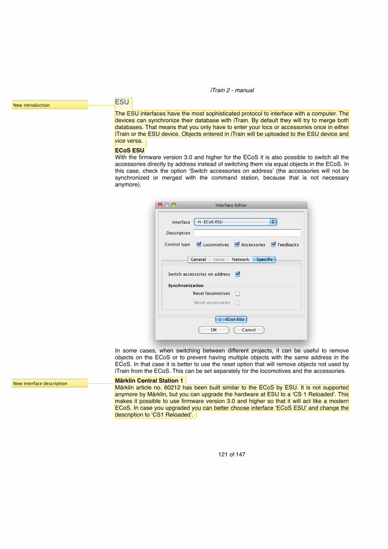
ESUThe ESU interfaces have the most sophisticated protocol to interface with a computer. The devices can synchronize their database with iTrain. By default they will try to merge both databases. That means that you only have to enter your locs or accessories once in either iTrain or the ESU device. Objects entered in iTrain will be uploaded to the ESU device and vice versa.ECoS ESUWith the firmware version 3.0 and higher for the ECoS it is also possible to switch all the accessories directly by address instead of switching them via equal objects in the ECoS. In this case, check the option ʻSwitch accessories on addressʼ (the accessories will not be synchronized or merged with the command station, because that is not necessary anymore).
In some cases, when switching between different projects, it can be useful to remove objects on the ECoS or to prevent having multiple objects with the same address in the ECoS. In that case it is better to use the reset option that will remove objects not used by iTrain from the ECoS. This can be set separately for the locomotives and the accessories.Märklin Central Station 1Märklin article no. 60212 has been built similar to the ECoS by ESU. It is not supported anymore by Märklin, but you can upgrade the hardware at ESU to a ʻCS 1 Reloadedʼ. This makes it possible to use firmware version 3.0 and higher so that it will act like a modern ECoS. In case you upgraded you can better choose interface ʻECoS ESUʼ and change the description to ʻCS1 Reloadedʼ.
iTrain 2 - manual
121 of 147
New introduction
New interface description

If you still have the original device, use this interface and do not use the ʻSwitch accessories on addressʼ option, because it has not been fully implemented in the firmware. The ʻSynchronizationʼ options work the same as on the ECoS interface.Note:! This interface requires firmware version 2.0.3 or 2.0.4 to be installed on the Central
Station 1. Older firmware versions are not supported.
iTrain 2 - manual
122 of 147

Märklin Central Station 2The Märklin Central station 2 (CS2) has no relation with the Central Station 1 and uses a completely different protocol based on the CAN-bus. Although this is a network interface it is based on UDP instead of TCP and that makes the configuration of the CS2 somewhat more difficult, because two connections have to be set up. One from the computer to the CS2 and one back from the CS2 to the computer. In general this second connection needs some attention, because it requires some settings on the CS2 on the tab ʻIPʼ and/or tab ʻCANʼ depending on the firmware version of the CS2.29
The interface continuously reads status data (also called channels) from the CS2, such as the voltage, current and temperature of all boosters (including the built-in one). In ʻChannel Intervalʼ you can specify how often this happens.For DCC locs you can specify whether the long or short address will be used based on an offset. All locs with addresses equal or higher than the specified value use the long
iTrain 2 - manual
123 of 147
29 Starting with firmware 1.5 on the CS2 you have to set the ʻCANʼ tab to ʻBroadcastʼ and specify the IP address of your computer as destination. With firmware 1.4 you have to specify in the ʻIPʼ tab the correct IP address of the CS2, enable the ʻGatewayʼ, and specify the IP address of your computer (and not that of the router).
New channel interval
New but checked with selectrix already.

address. This is relevant for the addresses from 1-127 that can be both short and long addresses.Depending on the setting ʻImport locomotivesʼ, iTrain will try to import the loc database from the CS2 when going ʻOnlineʼ and tries to merge the data with the data in iTrain. However, it cannot upload locs to the CS2, but in general that is no problem since non-MFX locs can also be controlled without an entry in the CS2.The CS2 has the possibility to directly connect S88 modules at the bottom of the device. To distinguish these S88 modules from other feedbacks modules directly connected to the CAN bus, you have to specify the number of S88 modules that are attached to the CS2 in the field ʻS88 Module countʼ.Starting with firmware version 1.6 it will automatically send out changes on the S88 on the network, but prior to version 1.6 the only option was to frequently request the state of all feedbacks (polling). The interval between the requests is the ʻFeedback Intervalʼ in milliseconds with a value of zero for no polling.Still the S88 connector on the CS2 is not ideal to read feedbacks via the CS 2, because it is not possible to specify the number of feedback modules in the CS2 itself and it will not read them all. It seems that it will be fixed in the near future by the manufacturer, but for large layouts I would consider using another digital system for reading the feedbacks in a reliable way, such as the HSI-S88 or the µCON-S88-Master. It is also possible to use the CAN-digital-Bahn feedback modules. They connect directly to the CAN-bus of the CS2 and notify their status.Tip: ! A workaround to specify the number of S88 modules on the CS2 is to create a
ʻmemoryʼ entry in the CS2 with an S88 contact number one higher than the highest one you use. This way the CS2 will at least scan all the modules that are needed in iTrain.
iTrain 2 - manual
124 of 147
Changed
Other options
refer to field
large layouts

XpressNetThis section contains a list of all interfaces that are based on the XpressNet protocol.Lenz XpressNet/X-Bus (Serial / USB / IP)Many interfaces are based on the XpressNet protocol from Lenz. Originally the system was called X-Bus, but since version 3 it is called XpressNet. The old locomotive commands used in X-Bus version 1 and 2 are also supported by this interface.Lenz itself delivers an interface with a serial port, one with a USB interface and one with an Ethernet or LAN interface, here called IP (=Internet Protocol) interface. In general the protocol is the same, but the USB and IP versions prefix the data with two extra bytes, so choosing the right interface is important.
The Lenz interfaces have the option ʻLocomotive polling Intervalʼ in milliseconds. XpressNet informs iTrain about many changes, but not of the state of handhelds that are controlling locs. However it does inform iTrain when a train is taken over by a handheld. iTrain will regularly read the locomotive information when a loc is taken over by a handheld, to know the speed and functions. A good default value is 100 ms.In the new XpressNet protocol version 3.6, support for extra functions f13-f28 has been added. In case you use this protocol version, you can check ʻUse new functionsʼ to be able to control them as well, but in case you donʼt know, just leave it off to prevent problems in the communication.There is some discussion about how the two accessory outputs should be interpreted among users of XpressNet. In case all your turnouts switch differently from what you would expect, you can use the last option to correct that at once.
iTrain 2 - manual
125 of 147
New intro
LAN
X-Bus also supported
New X-Bus history and support
Remove explanation

S88 XpressNet LIThe Roco Multimaus is very popular in start-sets, but it is not possible to connect it to a computer directly. There are some devices available on the internet that create an interface based on XPressNet via a serial port, and at the same time deliver support for connecting S88 modules and deliver their state via XpressNet. In the Netherlands the most well known device is the ʻS88XpressNetLIʼ.Next to the ʻLocomotive polling Intervalʼ that is described with Lenz XpressNet, there is another option that has to do with an issue with the ʻMultimausʼ concerning accessory addresses. Accessory decoders programmed with another DCC system at address 1 will have address 5 in the Multimaus. Even worse, decoders programmed at address 1-4 with a Multimaus may not even be visible with another DCC system. If you use a Multimaus, always program your accessories at address 5 or higher. In case you want this Multimaus address 5 to appear as 1 in iTrain, check the option ʻAccessory offset for Multimausʼ. This way it is easier to later migrate the project to another DCC command station when you outgrow the Multimaus.
The option ʻS88 base moduleʼ allows you to set an offset in the feedback address range for the S88 modules. It is configurable to prevent overlap with possible turnout feedback devices that have a fixed address space. Allowed values are 0-64. Zero means no S88 feedback. Value one means that the first S88 module uses feedback address 1-16 and so on.
iTrain 2 - manual
126 of 147

MoBaSbSThe ʻModellBahnSelbstbauSteuerungʼ or MoBaSbS is a system based on the XpressNet protocol and has some popularity in Germany. It works with both DCC and Motorola and also supports synchronizing the loc database in iTrain with the command station. In addition, it has extra commands to inform iTrain of changes in the loc speed, and therefore does not need polling.
It supports both the Lenz serial and Lenz USB protocol so you have to set the settings the same as the dipswitches on the MoBaSbS. The loc data of the MoBaSbS and iTrain are only synchronized when going ʻOnlineʼ. New loc data in iTrain is uploaded to the RAM of the MoBaSbS. To store back the loc database in EEPROM when going offline, select this option. The ʻUse new functionsʼ is provided in case the MoBaSbS will support the f13-f28 in the future, but currently it should be left unchecked. The last option is to swap the interpretation of the accessory outputs in case turnouts and signal switch in the opposite way.RocomotionRocomotion is a proprietary protocol used by Roco based on XpressNet, but with some additions for their own feedback modules (10787). This interface only supports the older 10785 device (with a serial port).The blue command station 10832 with a USB port is not supported via the USB and Rocomotion and we recommend to buy an ʻS88 XpressNet LIʼ to be able to use iTrain with this system.
iTrain 2 - manual
127 of 147
Changes

HornbyHornby is another interface based on XpressNet for the Hornby command stations, with the settings on the Serial tab adapted for this system. It is not officially supported, because I have not been able to test it myself. In case you are interested, contact us.
iTrain 2 - manual
128 of 147
Changed

SelectrixThis section contains a list of all interfaces that support the Selectrix SX-bus.SelectrixThis interface is the original Selectrix protocol with one SX-bus. It will read out the
complete SX-bus regularly to inform iTrain of changes on the bus. The time between reads is called the ʻEvent Intervalʼ. Because this process is quite slow, you have to use 250 ms when using a baudrate of 9600. With higher baudrates you can make the interval smaller and the reaction time will be better. Today there are new, faster protocols based on a Selectrix bus available that are also supported by iTrain.Rautenhaus SLXThe Rautenhaus SLX interface can be used for both the SLX825 and the SLX852. The SLX825 only supports one bus, while the SLX852 supports two buses and can also be used as an interface without a command station to only switch accessories and read feedbacks.
iTrain 2 - manual
129 of 147
New intro

Rautenhaus uses an efficient event mechanism that notifies changes on the bus so that no polling is necessary. You only have to configure if you want to use the extra channels (104-111), and in case you use a second bus you have to specify to which bus the accessories and feedbacks are connected.Rautenhaus RMXThe Rautenhaus RMX interface can be used for the command station RMX950USB or the separate interface RMX952. It automatically supports two buses where the first RMX bus (0) is for locomotives and the second SX bus (1) is for the accessories and feedbacks.
The loc database of iTrain and the RMX950 are synchronized when the interface is going ʻOnlineʼ. Selectrix, Selectrix2 and DCC locs are supported on this interface.
iTrain 2 - manual
130 of 147

For DCC locs you can specify whether the long or short address will be used based on an offset. All locs with addresses equal or higher than the specified value use the long address. This is relevant for the addresses from 1-127 that can be both short and long addresses.Müt 2004The Müt 2004 is a pure Selectrix command station with some extensions in the protocol to support multiple SX-buses. It also uses an efficient event mechanism that notifies changes on the bus so that no polling is necessary. Currently only SX-0 and SX-1 are supported in iTrain.
You only have to configure if you want to use the extra channels (104-111), and in case you use a second bus you have to specify to which bus the accessories and feedbacks are connected.FCC (Doehler & Haass / MTTM)The Future-Central-Control is a command station based on two Selectrix buses that next to Selectrix also supports Selectrix 2, DCC and Motorola locs. It is still necessary to read all the SX-bus data regularly, but because it uses a very high baudrate, the delays are minimal. A typical ʻEvent Intervalʼ can be 50-100 ms.It is possible to use a second bus for accessories and/or feedbacks. In case you use a second bus, you have to specify to which bus the accessories and feedbacks are connected.
iTrain 2 - manual
131 of 147
New Müt 2004 has to be added

The FCC is a multi protocol command station, but you have to configure the command station with the protocols that will be used. To change it you can use the box ʻLoc protocolsʼ. Only in case the value is not ʻKeep current protocolsʼ, the setting will be applied to the command station when going ʻOnlineʼ. This setting is not stored in iTrain sessions. To change it, select it here and go online and the used protocols in the command station will be changed and stored in the FCC. The next time you start iTrain the value in the box will be ʻKeep current protocolsʼ again.For DCC locs you can specify whether the long or short address will be used based on an offset. All addresses equal or higher than the specified value use the long address. This is relevant for the addresses from 1-127 that can be both short and long addresses.Stärz ZS1The Stärz ZS1 communicates identically to the Rautenhaus SLX that has been described before and has the same options.Stärz ZS2The Stärz ZS2 is a multi-protocol command station (you can update the ZS1 to a ZS2) that supports up to 16 locs of type Selectrix 2 or DCC in addition to all the Selectrix features of the ZS1.
iTrain 2 - manual
132 of 147

You can configure the protocols used on the track via the command station, but you can also can use the box ʻLoc protocolsʼ here. Only in case the value is not ʻKeep current protocolsʼ, the setting will be applied to the command station when going ʻOnlineʼ. This setting is not stored in iTrain sessions. To change it, select it here and go online and the used protocols in the command station will be changed and stored in the ZS2. The next time you start iTrain the value in the box will be ʻKeep current protocolsʼ again.For DCC locs you can specify whether the long or short address will be used based on an offset. All addresses equal or higher than the specified value use the long address. This is relevant for the addresses from 1-127 that can be both short and long addresses.
iTrain 2 - manual
133 of 147

ZimoThe Zimo interface has been developed for the MX1 command station with firmware version 3.06 only. Only locomotives and accessories are tested on this interface and will be officially supported, although the feedbacks have been implemented. No specific configuration is necessary.
Extra information about the voltage and current of the command station is displayed on the status bar.
iTrain 2 - manual
134 of 147

MassothThe Massoth interface has been developed for the DiMAX command stations with a firmware version 2.59 or higher. No specific configuration is necessary.
Information about the current and its limit will be visible on the status bar. If the protocol of the loc in iTrain conflicts with the one in the Massoth then iTrain will change it in the Massoth.
iTrain 2 - manual
135 of 147

VPEB / DinaSysThis section contains a list of all interfaces that are a result of the development of the Dinamo system to run analogue and digital locs on one layout by controlling every block individually. Except for the ʻDinamoʼ interface, all other interfaces are useful as a second interface next to any other non-Dinamo system as well.DinamoThe Dinamo interface works with firmware version 3.0 or higher on the RMU and can be connected to either the serial or the USB port.
The ʻTransmission Intervalʼ is configurable, but in general keep it on the default value of 5 ms. For DCC locs you can specify whether the long or short address will be used based on an offset. All addresses equal or higher than the specified value use the long address. This is relevant for the addresses from 1-127 that can be both short and long addresses.The ʻHFI levelʼ is the level for the front light of an analog loc. It is recommended to keep it below 12 so that direction changes are detected immediately. The ʻShunt accelerationʼ is the acceleration or inertia simulation by the Dinamo hardware for analog locs when the loc function ʻShuntʼ is activated. Zero means direct control.
iTrain 2 - manual
136 of 147
Slight change
New intro

The ʻInvert total polarityʼ option considers the polarity of all blocks to be the opposite. This is to prevent that most blocks need to have an ʻInvertedʼ polarity and only some a ʻStandardʼ polarity. If the polarity setting for all blocks looks correct and your analog loc is driving the wrong direction, then select this box.When using 3-rail track the analog locs should be modified to run DC instead of AC and you have to select ʻDC 3-railʼ so that polarity will be set correctly for 3-rail.The ʻFlash Period onʼ is a general setting that is currently not used by iTrain.OM32The OM32 interface works with both the OM32 and the OC32. The OM32 interface is normally used as an additional interface (lowercase s), because it can only control accessories.
By default the commands are sent directly to the OM32, even if new ones arrive while previous commands have not finished yet. In case every command absorbs a lot of power, this might give a peak current. By specifying a ʻMaximum queue countʼ greater than 0, queues will be created and commands will be executed in order per queue, but commands for different queues will be executed in parallel. The module number modulo the maximum queue count will determine the queue number. So if the queue count is equal to the number of OM32 modules, every module will work in parallel, but commands sent to the same module will be executed sequentially.For turnouts one output with a high (1) or low voltage (0) is used that naturally fits with servos. Relays and decouplers also use one output. Signals can use multiple outputs to connect all the different light bulbs or LEDs.NB:! You can also select this interface when you have got an OC32. The OC32 can be
controlled by either sending OM32 commands that are generated by iTrain, or by selecting the preprogrammed ʻAspectsʼ in the OC32. You can choose this per accessory. When using the ʻAspectsʼ, the number of outputs used is determined by the definition in the OC32.
iTrain 2 - manual
137 of 147
New Queue counts

OC32The OC32 interface only works with the OC32, but uses the same commands as the
OM32. It uses bidirectional communication instead of the unidirectional communication of the OM32, so it can also read data or confirm requests. Only use this if all the devices on the USB-RS485 converter are OC32 devices.The ʻTransmission Intervalʼ is configurable, but in general keep it on the default value of 20 ms.The ʻMaximum queue countʼ has been described in the OM32 interface section.PM32/OM32The PM32/OM32 is an experimental interface to use PM32, OM32 and OC32 devices separately from a Dinamo system on their own RS-485 network with the USB-RS485 converter. The PM32 is a device to switch 64 pulse driven devices like ordinary turnouts (no servos). The ʻTransmission Intervalʼ is configurable, but in general keep it on the default value of 20 ms.DTCThe DinaSys Turntable Control (DTC) is a complete solution for a turntable with the following features in combination with iTrain:• The position of the bridge will be changed with smooth movements by slowly
accelerating it at the start and decelerating the bridge near the end position.• It will read the actual position of the bridge at any time via sensors even when you
change it manually.• It allows the sidings connected to the turntable to be switched off via built-in relays30.
This is fully configurable in iTrain and explained later on.
iTrain 2 - manual
138 of 147
30 You can share one TM-H output for all sidings switched via relays in a Dinamo system reducing the costs.
New queue counts

The motor settings can be set under ʻSpeedʼ and ʻKick-startʼ. By pressing the button ʻDefaultʼ all values will be set to the factory settings. The speed settings are percentages of the maximum speed of the hardware.If the option ʻPolarity offsetʼ is set greater than zero, the internal polarity relay of the DTC will be switched based on the position of the turntable. The offset indicates the first connection with normal polarity and divides the turntable in two halves. If there are 48 connections and the polarity offset is 11, then the bridge will have normal polarity at position 11-34 and inverted polarity at position 35-48 and 1-10. This option is not necessary for Dinamo users as the polarity will already be switched on the block output of the TM-H, so they should leave it zero.Within the DTC interface two addresses have been reserved for special purposes. By defining an A/B relay with this interface and address 98, you can activate and release the emergency stop of the bridge. A relay with address 99 will show the state of the built-in polarity relay.
iTrain 2 - manual
139 of 147
New special addresses
New polarity offset

Littfinski Daten Technik (LDT)Digital-S-Inside 2 / DiCoStationThe DSI-2 interface is an interface developed for the DiCoStation. The DiCoStation is a device with an HSI-S88 USB built-in and it can be used as a command station by using the DSI software on a computer with the Windows operating system. This interface only supports version 2 of the DSI software that is XML based, and is not compatible with version 1 which is P50X protocol based.When the DSI software (DsiService.exe) runs on Windows it acts as an intermediate hub and iTrain connects over the network to the DsiService, so you have to specify a host name or IP address. Normally you will run iTrain and the DsiService.exe on the same computer, but is possible to run iTrain on another computer with for example Mac OS X or Linux.
The device number is normally 0, but can be changed if you are using more than one DiCoStation at the same time.For DCC locs you can specify whether the long or short address will be used based on an offset. All addresses equal or higher than the specified value use the long address. This is relevant for the addresses from 1-127 that can be both short and long addresses.HSI-S88The HSI-S88 interface only works with the serial version of the HSI-S88. The HSI-S88 is normally used as an additional interface, because it can only read feedbacks.
iTrain 2 - manual
140 of 147
New interface
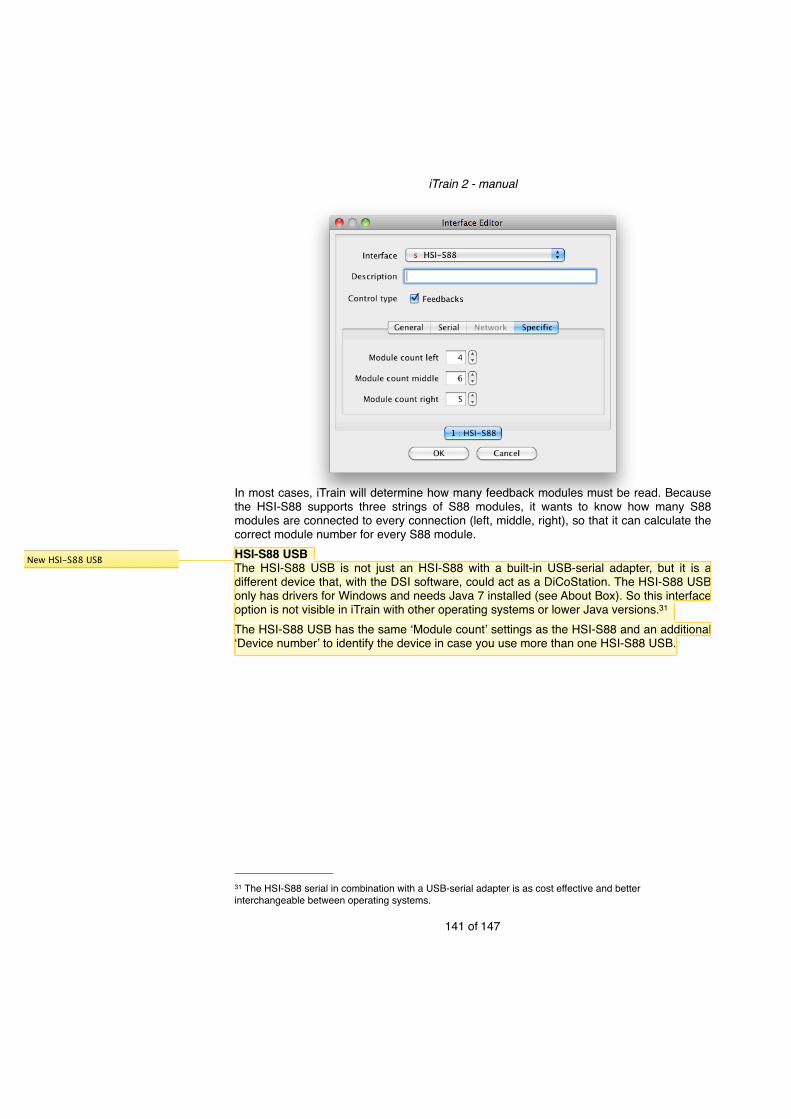
In most cases, iTrain will determine how many feedback modules must be read. Because the HSI-S88 supports three strings of S88 modules, it wants to know how many S88 modules are connected to every connection (left, middle, right), so that it can calculate the correct module number for every S88 module.HSI-S88 USBThe HSI-S88 USB is not just an HSI-S88 with a built-in USB-serial adapter, but it is a different device that, with the DSI software, could act as a DiCoStation. The HSI-S88 USB only has drivers for Windows and needs Java 7 installed (see About Box). So this interface option is not visible in iTrain with other operating systems or lower Java versions.31
The HSI-S88 USB has the same ̒ Module countʼ settings as the HSI-S88 and an additional ʻDevice numberʼ to identify the device in case you use more than one HSI-S88 USB.
iTrain 2 - manual
141 of 147
31 The HSI-S88 serial in combination with a USB-serial adapter is as cost effective and better interchangeable between operating systems.
New HSI-S88 USB

Lokstore DigitalµCon-S88-MasterThe µCON-S88-Master interface is a device to read in S88N modules from three strings, just like the HSI-S88, but it is a network interface and connects to the computer via Ethernet32. It has configurable options to filter the input and remove some distortions, resulting in a clean output. It is normally used as an additional interface, because it can only read feedbacks.
Because the µCON-S88-Master supports three strings of S88N modules, it wants to know how many S88 modules are connected to every connection (left, middle, right), so that it can calculate the correct module number for every S88 module.µCON-ManagerThe µCON-Manager in combination with the µCON-Boosters is a command station independent booster system. The µCON-Manager interface is normally used as an additional interface next to a command station, because it can only read boosters.
iTrain 2 - manual
142 of 147
32 An Ethernet interface works on any modern operating system without additional drivers (USB always needs vendor specific drivers).
Note on Ethernet and drivers
New µCON-S88-Master
New µCON-Manager

The interface continuously reads status data (also called channels) via the manager, such as the voltage and current of all boosters. In ʻChannel Intervalʼ you can specify how often this happens.Note:! The current interface implementation in iTrain does not support the possibility to switch off specific boosters individually and make this visible in the layout or reroute trains based on this information.
iTrain 2 - manual
143 of 147

CAN-digital-BahnThe CAN-digital-Bahn project is a set of devices based on the CAN-bus developed by Thorsten Mumm.CAN-Control-SchnitteThe ʻCAN-Control-Schnitteʼ or shortly ʻCC-Schnitteʼ is the connection between the Märklin Gleisbox, the computer and other modules of the CAN-Digital-Project all connected via a CAN bus. It is a full interface that supports the loc protocols DCC, Motorola and MFX, accessories in DCC and Motorola format and feedbacks such as the ʻGleisReporterʼ or ʻStromSnifferʼ.
The interface continuously reads status data (also called channels) from the command station such as the voltage, current and temperature of all boosters (including the built-in one). In ʻChannel Intervalʼ you can specify how often this happens.For DCC locs you can specify whether the long or short address will be used based on an offset. All locs with addresses equal or higher than the specified value use the long address. This is relevant for the addresses from 1-127 that can be both short and long addresses.The registration of new MFX locomotives is done by iTrain. MFX locs will only announce themselves if they think they are new to the system. The decision of a loc to announce itself is based on an MFX counter value that it reads from the track. By increasing this value all locs that are not on the tracks when the interface goes online will announce themselves when they are put on the track.In practice it means that this value should be set once to a value comparable to the number of MFX locs you have (with a minimum of 5) and it should only be increased when you delete locs from iTrain.
iTrain 2 - manual
144 of 147
New intro
New channel interval
New but checked with selectrix already.

NB:! The ʻCC-Schnitteʼ communicates with a relatively high baudrate of 500,000 Baud. This speed is only supported on Windows for serial port communications. To use this interface with this speed on Mac OS X or Linux, you have to install the FTDI D2xx drivers and remove the FTDI VCP drivers.
CAN-PC-SchnitteThe ʻCAN-PC-Schnitteʼ interface is normally used as an additional interface, because it
can only read feedbacks. It is similar in functionality to the HSI-S88, but using the reliable CAN bus in combination with feedback modules called ʻGleisReporterʼ or ʻStromSnifferʼ. It has a USB-connector and requires no specific configuration.
iTrain 2 - manual
145 of 147

RailComRailCom detectors can read the address of loc decoders that support it and show this number on the switchboard in a feedback element.
When using blocks and attaching the feedback to a block (for example as an extra feedback), the address will be matched with the name of a loc and this name will be shown in the block element. This can be used to automatically detect locs in blocks that are put on the track without manual intervention.TAMS RailCom LinkThe TAMS RailCom Link is an additional interface only for feedbacks to read RailCom detectors.
When reading out a CV value of a loc decoder with another device (for example, a throttle or command station), it will show the CV value on the status bar.No specific configuration is necessary.
iTrain 2 - manual
146 of 147
New section

Games on TrackGames on Track GT-positionThe GoT GT-P is an additional interface only for feedbacks to use the virtual blocks in GT-Position as feedbacks in iTrain. It is a network interface, because it connects to the GT-P software via a network socket. The GT-P software only works on Windows.
No specific configuration in iTrain is necessary, but in GT-P you have to specify the name of the feedback in iTrain in the comment field of the virtual block or use the same name in both software.Instead, it is possible to specify the iTrain feedback address in the comment field by prefixing it with a # (for example #34). It is not necessary to give GT-P feedbacks in iTrain an address, because this would lead to extra administration. The only advantage would be that you can use the Feedback monitor and that you can change feedbacks names in iTrain without affecting the settings in GT-P.
iTrain 2 - manual
147 of 147
New interface GT-P