
iTHERM TM411 Technical Information - … TM411 2 Endress+Hauser Table of contents Function and...
52
Easy-to-use metric version with outstanding sensor technology Applications • Specially designed for use in hygienic and aseptic applications in the Food & Beverages and Life Sciences industries • Measuring range: –200 to +600 °C (–328 to +1 112 °F) • Pressure range up to 50 bar (725 psi) • Protection class: up to IP69K Head transmitter All Endress+Hauser transmitters are available with enhanced accuracy and reliability compared to directly wired sensors. Easy customizing by choosing one of the following outputs and communication protocols: • Analog output 4 to 20 mA, HART ® • PROFIBUS ® PA, FOUNDATION Fieldbus™ Your benefits • User-friendly and reliable from product selection to maintenance • iTHERM inserts: globally unique, automated production. Full traceability and consistently high product quality for reliable measured values • iTHERM QuickSens: fastest response times (t 90s : 1.5 s) for optimum process control • iTHERM StrongSens: unsurpassed vibration resistance (> 60g) for ultimate plant safety • iTHERM QuickNeck – cost and time savings thanks to simple, tool-free recalibration • iTHERM TA30R: 316L terminal head for easier handling and lower installation and maintenance costs, and with highest IP69K rating • International certification: explosion protection e.g. ATEX/IECEx and in compliance with hygiene standards according to 3-A ® , EHEDG, ASME BPE, FDA, TSE Certificate of Suitability Products Solutions Services Technical Information iTHERM TM411 Trend-setting, modular resistance thermometer for hygienic and aseptic applications TI01038T/09/EN/05.15 71306162
-
Upload
duongduong -
Category
Documents
-
view
227 -
download
0
Transcript of iTHERM TM411 Technical Information - … TM411 2 Endress+Hauser Table of contents Function and...

Easy-to-use metric version with outstandingsensor technology
Applications
• Specially designed for use in hygienic and aseptic applications in the Food &Beverages and Life Sciences industries
• Measuring range: –200 to +600 °C (–328 to +1 112 °F)• Pressure range up to 50 bar (725 psi)• Protection class: up to IP69K
Head transmitter
All Endress+Hauser transmitters are available with enhanced accuracy and reliabilitycompared to directly wired sensors. Easy customizing by choosing one of thefollowing outputs and communication protocols:
• Analog output 4 to 20 mA, HART®
• PROFIBUS® PA, FOUNDATION Fieldbus™
Your benefits
• User-friendly and reliable from product selection to maintenance• iTHERM inserts: globally unique, automated production. Full traceability and
consistently high product quality for reliable measured values• iTHERM QuickSens: fastest response times (t90s: 1.5 s) for optimum process control• iTHERM StrongSens: unsurpassed vibration resistance (> 60g) for ultimate plant
safety• iTHERM QuickNeck – cost and time savings thanks to simple, tool-free
recalibration• iTHERM TA30R: 316L terminal head for easier handling and lower installation
and maintenance costs, and with highest IP69K rating• International certification: explosion protection e.g. ATEX/IECEx and in compliance
with hygiene standards according to 3-A®, EHEDG, ASME BPE, FDA, TSECertificate of Suitability
Products Solutions Services
Technical InformationiTHERM TM411Trend-setting, modular resistance thermometerfor hygienic and aseptic applications
TI01038T/09/EN/05.1571306162
iTHERM TM411
2 Endress+Hauser
Table of contents
Function and system design . . . . . . . . . . . . . . . . . . . 3iTHERM Hygiene line . . . . . . . . . . . . . . . . . . . . . . . . . . . 3Measuring principle . . . . . . . . . . . . . . . . . . . . . . . . . . . . 3Measuring system . . . . . . . . . . . . . . . . . . . . . . . . . . . . . 4Modular design . . . . . . . . . . . . . . . . . . . . . . . . . . . . . . . 5
Input . . . . . . . . . . . . . . . . . . . . . . . . . . . . . . . . . . . . . 6Measured variable . . . . . . . . . . . . . . . . . . . . . . . . . . . . . 6Measuring range . . . . . . . . . . . . . . . . . . . . . . . . . . . . . . 6
Output . . . . . . . . . . . . . . . . . . . . . . . . . . . . . . . . . . . 6Output signal . . . . . . . . . . . . . . . . . . . . . . . . . . . . . . . . 6Family of temperature transmitters . . . . . . . . . . . . . . . . . 6
Wiring . . . . . . . . . . . . . . . . . . . . . . . . . . . . . . . . . . . 7Wiring diagrams for RTD . . . . . . . . . . . . . . . . . . . . . . . . 7Cable entries . . . . . . . . . . . . . . . . . . . . . . . . . . . . . . . . 8Connectors . . . . . . . . . . . . . . . . . . . . . . . . . . . . . . . . . . 8Overvoltage protection . . . . . . . . . . . . . . . . . . . . . . . . . 10
Performance characteristics . . . . . . . . . . . . . . . . . . 10Reference conditions . . . . . . . . . . . . . . . . . . . . . . . . . . 10Accuracy . . . . . . . . . . . . . . . . . . . . . . . . . . . . . . . . . . 11Influence of ambient temperature . . . . . . . . . . . . . . . . . 11Self heating . . . . . . . . . . . . . . . . . . . . . . . . . . . . . . . . 11Response time . . . . . . . . . . . . . . . . . . . . . . . . . . . . . . 12Calibration . . . . . . . . . . . . . . . . . . . . . . . . . . . . . . . . . 13Insulation resistance . . . . . . . . . . . . . . . . . . . . . . . . . . 15
Installation . . . . . . . . . . . . . . . . . . . . . . . . . . . . . . . 16Orientation . . . . . . . . . . . . . . . . . . . . . . . . . . . . . . . . 16Installation instructions . . . . . . . . . . . . . . . . . . . . . . . . 16
Environment . . . . . . . . . . . . . . . . . . . . . . . . . . . . . . 18Ambient temperature range . . . . . . . . . . . . . . . . . . . . . 18Storage temperature . . . . . . . . . . . . . . . . . . . . . . . . . . 18Humidity . . . . . . . . . . . . . . . . . . . . . . . . . . . . . . . . . . 18Climate class . . . . . . . . . . . . . . . . . . . . . . . . . . . . . . . 18Degree of protection . . . . . . . . . . . . . . . . . . . . . . . . . . 18Shock and vibration resistance . . . . . . . . . . . . . . . . . . . . 18Electromagnetic compatibility (EMC) . . . . . . . . . . . . . . . 19
Process . . . . . . . . . . . . . . . . . . . . . . . . . . . . . . . . . . 19Process temperature range . . . . . . . . . . . . . . . . . . . . . . 19Thermal shock . . . . . . . . . . . . . . . . . . . . . . . . . . . . . . 19Process pressure range . . . . . . . . . . . . . . . . . . . . . . . . . 19Medium - state of aggregation . . . . . . . . . . . . . . . . . . . . 19
Mechanical construction . . . . . . . . . . . . . . . . . . . . 20Design, dimensions . . . . . . . . . . . . . . . . . . . . . . . . . . . 20Insert . . . . . . . . . . . . . . . . . . . . . . . . . . . . . . . . . . . . 30Weight . . . . . . . . . . . . . . . . . . . . . . . . . . . . . . . . . . . 30Material . . . . . . . . . . . . . . . . . . . . . . . . . . . . . . . . . . 30Surface roughness . . . . . . . . . . . . . . . . . . . . . . . . . . . 31Terminal heads . . . . . . . . . . . . . . . . . . . . . . . . . . . . . . 31Extension neck . . . . . . . . . . . . . . . . . . . . . . . . . . . . . . 33
Protection tube . . . . . . . . . . . . . . . . . . . . . . . . . . . . . . 35
Certificates and approvals . . . . . . . . . . . . . . . . . . . 43CE mark . . . . . . . . . . . . . . . . . . . . . . . . . . . . . . . . . . . 43Hygiene standard . . . . . . . . . . . . . . . . . . . . . . . . . . . . 43Ex approval . . . . . . . . . . . . . . . . . . . . . . . . . . . . . . . . 43Other standards and guidelines . . . . . . . . . . . . . . . . . . . 43Parts in contact with the medium . . . . . . . . . . . . . . . . . . 43Surface roughness . . . . . . . . . . . . . . . . . . . . . . . . . . . . 43Material resistance . . . . . . . . . . . . . . . . . . . . . . . . . . . 43Material certification . . . . . . . . . . . . . . . . . . . . . . . . . . 43Calibration . . . . . . . . . . . . . . . . . . . . . . . . . . . . . . . . . 43Protection tube testing and load capacity calculation . . . . . 44
Ordering information . . . . . . . . . . . . . . . . . . . . . . . 44
Accessories . . . . . . . . . . . . . . . . . . . . . . . . . . . . . . . 44Device-specific accessories . . . . . . . . . . . . . . . . . . . . . . 45Communication-specific accessories . . . . . . . . . . . . . . . . 47Service-specific accessories . . . . . . . . . . . . . . . . . . . . . . 48System components . . . . . . . . . . . . . . . . . . . . . . . . . . . 49
Documentation . . . . . . . . . . . . . . . . . . . . . . . . . . . . 49

iTHERM TM411
Endress+Hauser 3
Function and system design
iTHERM Hygiene line This thermometer is part of the product line of modular thermometers for hygienic and asepticapplications.
Differentiating factors when selecting a suitable thermometer
TM4x1 TM4x2
Metric version Imperial version
↓ ↓
TMx1x characterizes the device that uses cutting-edge technology, with features such as a replaceable insert,quick-fastening extension neck (iTHERM QuickNeck), vibration-resistant and fast-response sensor technology
(iTHERM StrongSens and QuickSens) and approval for use in hazardous areas
TM411
mm
A0018239
TM412
inch
A0018691
↓ ↓
TMx0x characterizes the device that uses basic technology, with features such as a fixed, non-replaceableinsert, application in non-hazardous areas, standard extension neck, low-cost unit
TM401
mm
A0018692
TM402
inch
A0018693
Measuring principle Resistance thermometer (RTD)
These resistance thermometers use a Pt100 temperature sensor according to IEC 60751. Thetemperature sensor is a temperature-sensitive platinum resistor with a resistance of 100 Ω at0 °C (32 °F) and a temperature coefficient α = 0.003851 °C-1.

iTHERM TM411
4 Endress+Hauser
There are generally two different kinds of platinum resistance thermometers:• Wire wound (WW): Here, a double coil of fine, high-purity platinum wire is located in a ceramic
support. This is then sealed top and bottom with a ceramic protective layer. Such resistancethermometers not only facilitate very reproducible measurements but also offer good long-termstability of the resistance/temperature characteristic within temperature ranges up to600 °C (1 112 °F). This type of sensor is relatively large in size and it is comparatively sensitive tovibrations.
• Thin film platinum resistance thermometers (TF): A very thin, ultrapure platinum layer,approx. 1 μm thick, is vaporized in a vacuum on a ceramic substrate and then structuredphotolithographically. The platinum conductor paths formed in this way create the measuringresistance. Additional covering and passivation layers are applied and reliably protect the thinplatinum layer from contamination and oxidation, even at high temperatures.
The primary advantages of thin film temperature sensors over wire wound versions are their smallersizes and better vibration resistance. A relatively low principle-based deviation of the resistance/temperature characteristic from the standard characteristic of IEC 60751 can frequently be observedamong TF sensors at high temperatures. As a result, the tight limit values of tolerance category A asper IEC 60751 can only be observed with TF sensors at temperatures up to approx. 300 °C (572 °F).For this reason, thin-film sensors are generally only used for temperature measurements in rangesbelow 400 °C (752 °F).
Measuring system Endress+Hauser offers a complete portfolio of optimized components for the temperature measuringpoint – everything you need for the seamless integration of the measuring point into the overallfacility. This includes:• Power supply unit/barrier• Display units• Overvoltage protection
For more information, see the brochure 'System Components - Solutions for a CompleteMeasuring Point' (FA00016K/EN)
Commubox
FieldCare
1
PLC
°C
2
3
A0017693
1 Example of application, measuring point layout with additional Endress+Hauser components
1 Installed iTHERM resistance thermometer with integrated HART® head transmitter2 RIA16 field display unit - The display unit records the analog measuring signal from the head transmitter and
shows this on the display. The LC display shows the current measured value in digital form and as a bar graphindicating a limit value violation. The display unit is looped into the 4 to 20 mA circuit and gets the requiredenergy from there. More information on this can be found in the Technical Information, see "Documentation",→ 49.
3 Active barrier RN221N - The RN221N (24 V DC, 30 mA) active barrier has a galvanically isolated output forsupplying voltage to loop-powered transmitters. The universal power supply works with an input supplyvoltage of 20 to 250 V DC/AC, 50/60 Hz, which means that it can be used in all international power grids.More information on this can be found in the Technical Information, see "Documentation", → 49.
iTHERM TM411
Endress+Hauser 5
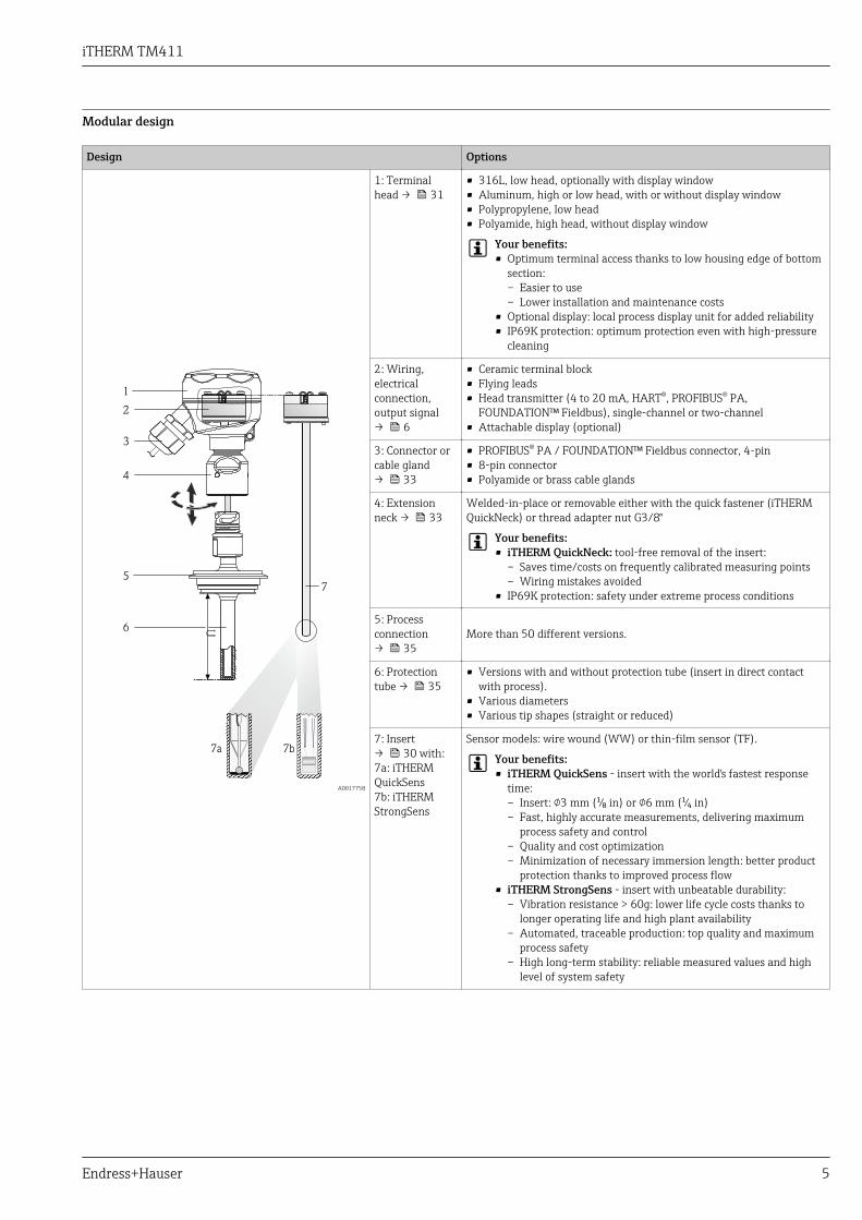
Modular design
Design Options
U
1
2
3
4
5
6
7
7a 7b
A0017758
1: Terminalhead → 31
• 316L, low head, optionally with display window• Aluminum, high or low head, with or without display window• Polypropylene, low head• Polyamide, high head, without display window
Your benefits:• Optimum terminal access thanks to low housing edge of bottom
section:– Easier to use– Lower installation and maintenance costs
• Optional display: local process display unit for added reliability• IP69K protection: optimum protection even with high-pressure
cleaning
2: Wiring,electricalconnection,output signal→ 6
• Ceramic terminal block• Flying leads• Head transmitter (4 to 20 mA, HART®, PROFIBUS® PA,
FOUNDATION™ Fieldbus), single-channel or two-channel• Attachable display (optional)
3: Connector orcable gland→ 33
• PROFIBUS® PA / FOUNDATION™ Fieldbus connector, 4-pin• 8-pin connector• Polyamide or brass cable glands
4: Extensionneck → 33
Welded-in-place or removable either with the quick fastener (iTHERMQuickNeck) or thread adapter nut G3/8"
Your benefits:• iTHERM QuickNeck: tool-free removal of the insert:
– Saves time/costs on frequently calibrated measuring points– Wiring mistakes avoided
• IP69K protection: safety under extreme process conditions
5: Processconnection→ 35
More than 50 different versions.
6: Protectiontube → 35
• Versions with and without protection tube (insert in direct contactwith process).
• Various diameters• Various tip shapes (straight or reduced)
7: Insert→ 30 with:7a: iTHERMQuickSens7b: iTHERMStrongSens
Sensor models: wire wound (WW) or thin-film sensor (TF).
Your benefits:• iTHERM QuickSens - insert with the world's fastest response
time:– Insert: 3 mm (¹⁄₈ in) or 6 mm (¹⁄₄ in)– Fast, highly accurate measurements, delivering maximum
process safety and control– Quality and cost optimization– Minimization of necessary immersion length: better product
protection thanks to improved process flow• iTHERM StrongSens - insert with unbeatable durability:
– Vibration resistance > 60g: lower life cycle costs thanks tolonger operating life and high plant availability
– Automated, traceable production: top quality and maximumprocess safety
– High long-term stability: reliable measured values and highlevel of system safety
iTHERM TM411
6 Endress+Hauser
Input
Measured variable Temperature (temperature-linear transmission behavior)
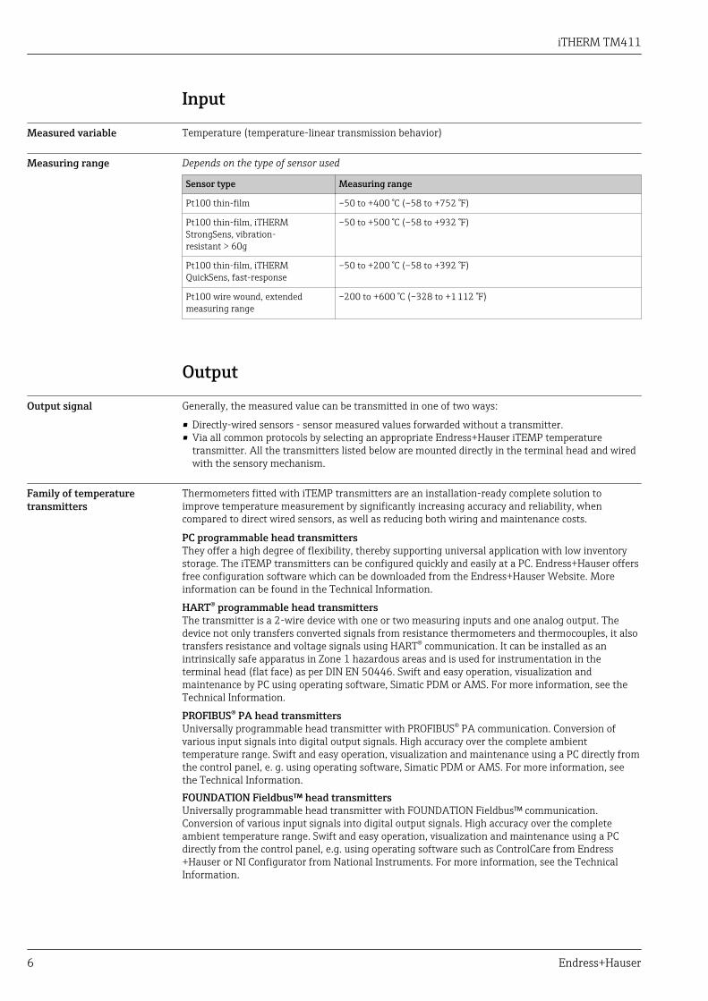
Measuring range Depends on the type of sensor used
Sensor type Measuring range
Pt100 thin-film –50 to +400 °C (–58 to +752 °F)
Pt100 thin-film, iTHERMStrongSens, vibration-resistant > 60g
–50 to +500 °C (–58 to +932 °F)
Pt100 thin-film, iTHERMQuickSens, fast-response
–50 to +200 °C (–58 to +392 °F)
Pt100 wire wound, extendedmeasuring range
–200 to +600 °C (–328 to +1 112 °F)
Output
Output signal Generally, the measured value can be transmitted in one of two ways:
• Directly-wired sensors - sensor measured values forwarded without a transmitter.• Via all common protocols by selecting an appropriate Endress+Hauser iTEMP temperature
transmitter. All the transmitters listed below are mounted directly in the terminal head and wiredwith the sensory mechanism.
Family of temperaturetransmitters
Thermometers fitted with iTEMP transmitters are an installation-ready complete solution toimprove temperature measurement by significantly increasing accuracy and reliability, whencompared to direct wired sensors, as well as reducing both wiring and maintenance costs.
PC programmable head transmittersThey offer a high degree of flexibility, thereby supporting universal application with low inventorystorage. The iTEMP transmitters can be configured quickly and easily at a PC. Endress+Hauser offersfree configuration software which can be downloaded from the Endress+Hauser Website. Moreinformation can be found in the Technical Information.
HART® programmable head transmittersThe transmitter is a 2-wire device with one or two measuring inputs and one analog output. Thedevice not only transfers converted signals from resistance thermometers and thermocouples, it alsotransfers resistance and voltage signals using HART® communication. It can be installed as anintrinsically safe apparatus in Zone 1 hazardous areas and is used for instrumentation in theterminal head (flat face) as per DIN EN 50446. Swift and easy operation, visualization andmaintenance by PC using operating software, Simatic PDM or AMS. For more information, see theTechnical Information.
PROFIBUS® PA head transmittersUniversally programmable head transmitter with PROFIBUS® PA communication. Conversion ofvarious input signals into digital output signals. High accuracy over the complete ambienttemperature range. Swift and easy operation, visualization and maintenance using a PC directly fromthe control panel, e. g. using operating software, Simatic PDM or AMS. For more information, seethe Technical Information.FOUNDATION Fieldbus™ head transmittersUniversally programmable head transmitter with FOUNDATION Fieldbus™ communication.Conversion of various input signals into digital output signals. High accuracy over the completeambient temperature range. Swift and easy operation, visualization and maintenance using a PCdirectly from the control panel, e.g. using operating software such as ControlCare from Endress+Hauser or NI Configurator from National Instruments. For more information, see the TechnicalInformation.

iTHERM TM411
Endress+Hauser 7
Advantages of the iTEMP transmitters:• Dual or single sensor input (optionally for certain transmitters)• Unsurpassed reliability, accuracy and long-term stability in critical processes• Mathematical functions• Monitoring of the thermometer drift, sensor backup functionality, sensor diagnostic functions• Sensor-transmitter matching for dual sensor input transmitter, based on Callendar/Van Dusen
coefficients
Wiring• According to the 3-A® Standard electrical connecting cables must be smooth, corrosion-
resistant and easy to clean.• Grounding or shield connections are possible via special ground terminals on the terminal
head. → 31
Wiring diagrams for RTD Type of sensor connection
Head mounted transmitter TMT18x (single input)
3
5
6RTD
34
56
RTD
1
2
3-wire 4-wire
Power supply
head transmitter and
analog output 4 to 20 mA,
or bus connection
(red) (red)(red) (red)
(white) (white)(white)
mA
A0016433-EN
Head mounted transmitter TMT8x (dual input)
-
+
+1
-2
7
6
5
4
3
1
2
76
5
4
3
Sensor input 2 Sensor input 1
RTD - and 3-wire: 4RTD 3-wire:
Bus connection
and supply voltage
Display connection
red
white
red red
red
whitewhite
(black)
(black)
(yellow)
A0008848-EN

iTHERM TM411
8 Endress+Hauser
Terminal block mounted
1 x Pt1001 x Pt100 2 x Pt100
red
red
white
black
4 wires 3 wires 3 wires
white
red
red
black
yellow
red
white
red
white
A0008591-EN
Cable entries See 'Terminal heads' section → 31
Connectors Endress+Hauser offers a wide variety of connectors for the simple and fast integration of thethermometer into a process control system. The following tables show the PIN assignments of thevarious plug connector combinations.
Abbreviations
#1 Order: first transmitter/insert #2 Order: secondtransmitter/insert
i Insulated. Wires marked 'i' are not connected and areinsulated with heat shrink tubes.
YE Yellow
GND Grounded. Wires marked 'GND' are connected to theinternal grounding screw in the terminal head.
RD Red
BN Brown WH White
GNYE Green-yellow PK Pink
BU Blue GN Green
GY Gray BK Black
Terminal head with one cable entry
Plug 1x PROFIBUS PA 1x FOUNDATION™Fieldbus (FF) 8-pin
Plug thread M12 7/8" 7/8" M12
PIN number 1 2 3 4 1 2 3 4 1 2 3 4 1 2 3 4 5 6 7 8
Electrical connection (terminal head)
Flying leads Not connected (not insulated)
3-wire terminalblock (1x Pt100)
RD RDWH
RD RDWH
RD RDWH
RD RD
WHi
4-wire terminalblock (1x Pt100)
WH WH WH WH WH WH WH WH
6-wire terminalblock (2x Pt100)
RD(#1)
1)
RD(#1)
1)WH (#1) 1)
RD(#1)
1)
RD(#1)
1)WH (#1) 1)
RD(#1)
1)
RD(#1)
1)WH (#1) 1) WH BK BK YE
1x TMT 4 to 20mA or HART® + i - i + i - i + i - i
+(#1) i -
(#1) i
i
2x TMT 4 to 20mA or HART® in
the terminalhead with a high
cover
+(#1)
+(#2)
-(#1)
-(#2)
+(#1)
+(#2)
-(#1)
-(#2)
+(#1)
+(#2)
-(#1)
-(#2)
+(#2) i -
(#2) i
1x TMTPROFIBUS® PA + i - GND
2) + i - GND
2) Cannot be combined Cannot be combined

iTHERM TM411
Endress+Hauser 9
Plug 1x PROFIBUS PA 1x FOUNDATION™Fieldbus (FF) 8-pin
2x TMTPROFIBUS® PA
+(#1)
-(#1) + -
1x TMT FFCannot be combined Cannot be combined
- +GND i Cannot be combined
2x TMT FF -(#1)
+(#1)
PIN position andcolor code
1 BN
2 GNYE
3 BU
4 GY1
4 3
2
A0018929
1 BN
2 GNYE
3 BU
4 GY
1
4
3
2
A0018930
1 BU
2 BN
3 GY
4 GNYE
1
4
3
2
A0018931
1 WH
2 BN3 GN
4 YE
5 GY6 PK
7 BU
8 RD
A0018927
1) Second Pt100 is not connected2) If a plastic housing TA30S or TA30P is used, insulated 'i' instead of grounded GND
Terminal head with two cable entries
Plug 2x PROFIBUS® PA 2x FOUNDATION™ Fieldbus (FF)
Plug thread
#1 #2
A0021706
M12(#1) / M12(#2) 7/8"(#1) / 7/8"(#2) 7/8"(#1) / 7/8"(#2)
PIN number 1 2 3 4 1 2 3 4 1 2 3 4
Electrical connection (terminal head)
Flying leads Not connected (not insulated)
3-wire terminal block (1x Pt100)RD/i RD/i
WH/iRD/i RD/i
WH/iRD/i RD/i
WH/i
4-wire terminal block (1x Pt100) WH/i WH/i WH/i WH/i WH/i WH/i
6-wire terminal block (2x Pt100) RD/BK RD/BK WH/YE RD/BK RD/BK WH/YE RD/BK RD/BK WH/YE
1x TMT 4 to 20 mA or HART® +/i
i/i
-/ii/i
+/i
i/i
-/ii/i
+/ii/i
-/ii/i2x TMT 4 to 20 mA or HART® in the
terminal head with a high cover+(#1)/+(#2)
-(#1)/-(#2)
+(#1)/+(#2)
-(#1)/-(#2)
+(#1)/+(#2)
-(#1)/-(#2)
1x TMT PROFIBUS® PA +/i -/iGND/GND
+/i -/iGND/GND Cannot be combined
2x TMT PROFIBUS® PA +(#1)/+(#2)
-(#1)/-(#2)
+(#1)/+(#2)
-(#1)/-(#2)
1x TMT FFCannot be combined Cannot be combined
-/i +/ii/i GND/
GND2x TMT FF -(#1)/-(#2)
+(#1)/+(#2)
PIN position and color code
1 BN
2 GNYE
3 BU
4 GY1
4 3
2
A0018929
1 BN
2 GNYE
3 BU
4 GY
1
4
3
2
A0018930
1 BU
2 BN
3 GY
4 GNYE
1
4
3
2
A0018931

iTHERM TM411
10 Endress+Hauser
Connection combination: insert - transmitter
InsertTransmitter connection 1)
1x 1-channel 2x 1-channel 2) 1x 2-channel 2x 2-channel 2)
1x Pt100, flyingleads Pt100 (#1) : transmitter (#1)
Pt100 (#1) : transmitter (#1)(Transmitter (#2) not
connected)Pt100 (#1) : transmitter (#1) Pt100 (#1) : transmitter (#1)
Transmitter (#2) not connected
2x Pt100, flyingleads
Pt100 (#1) : transmitter (#1)Pt100 (#2) insulated
Pt100 (#1) : transmitter (#1)Pt100 (#2): transmitter (#2)
Pt100 (#1) : transmitter (#1)Pt100 (#2) : transmitter (#1)
Pt100 (#1) : transmitter (#1)Pt100 (#2) : transmitter (#1)
(Transmitter (#2) notconnected)
1x Pt100 withterminal block 2)
Pt100 (#1) : transmitter incover
Cannot be combined
Pt100 (#1) : transmitter incover
Cannot be combined2x Pt100 with
terminal block 2)
Pt100 (#1) : transmitter incover
Pt100 (#2) not connected
Pt100 (#1) : transmitter incover
Pt100 (#2) : transmitter incover
1) If 2 transmitters are selected in a terminal head, transmitter (#1) is installed directly on the insert. Transmitter (#2) is installed in the high cover.A TAG cannot be ordered for the 2nd transmitter as standard. The bus address is set to the default value and, if necessary, must be changedmanually before commissioning.
2) Only in the terminal head with a high cover, only 1 transmitter possible. A ceramic terminal block is automatically fitted on the insert.
Overvoltage protection To protect against overvoltage in the power supply and signal/communication cables for thethermometer electronics, Endress+Hauser offers the HAW562 surge arrester for DIN rail mountingand the HAW569 for field housing installation.
For more information see the Technical Information 'HAW562 Surge arrester' TI01012K and'HAW569 Surge arrester' TI01013K.
Performance characteristics
Reference conditions These data are relevant for determining the accuracy of the temperature transmitters used. Moreinformation on this can be found in the Technical Information of the iTEMP temperaturetransmitters. → 49

iTHERM TM411
Endress+Hauser 11
Accuracy RTD resistance thermometer as per IEC 60751
Class Max. tolerances (°C) Characteristics
Cl. AA, former 1/3Cl. B
± (0.1 + 0.0017 · |t| 1))
A
AA
-200 -100 0 100 200 300 400 500 600°C
0.5
1.0
1.5
2.0
B
2.5
3.0
- 0.5
- 1.0
- 1.5
- 2.0
- 2.5
- 3.0
B
A
AA
Max. deviation (°C)
Max. deviation (°C)
A0008588-EN
Cl. A ± (0.15 + 0.002 · |t|)
Cl. B ± (0.3 + 0.005 · |t|)
Temperature ranges for compliance with thetolerance classes
Wire woundsensor (WW):
Cl. A Cl. AA
–100 to+450 °C
–50 to +250 °C
Thin-film version(TF):
Cl. A Cl. AA
• Standard• iTHERM
QuickSens• iTHERM
StrongSens
–30 to +300 °C–30 to +200 °C
–30 to +300 °C
0 to +150 °C0 to +200 °C
0 to +200 °C
1) |t| = absolute value °C
In order to obtain the maximum tolerances in °F, the results in °C must be multiplied by a factorof 1.8.
Influence of ambienttemperature
Depends on the head transmitter used. For details, see Technical Information. → 49
Self heating RTD elements are passive resistances that are measured using an external current. Thismeasurement current causes a self-heating effect in the RTD element itself which in turn creates anadditional measurement error. In addition to the measurement current, the size of the measurementerror is also affected by the temperature conductivity and flow velocity of the process. This self-heating error is negligible when an Endress+Hauser iTEMP temperature transmitter (very smallmeasurement current) is connected.
iTHERM TM411
12 Endress+Hauser
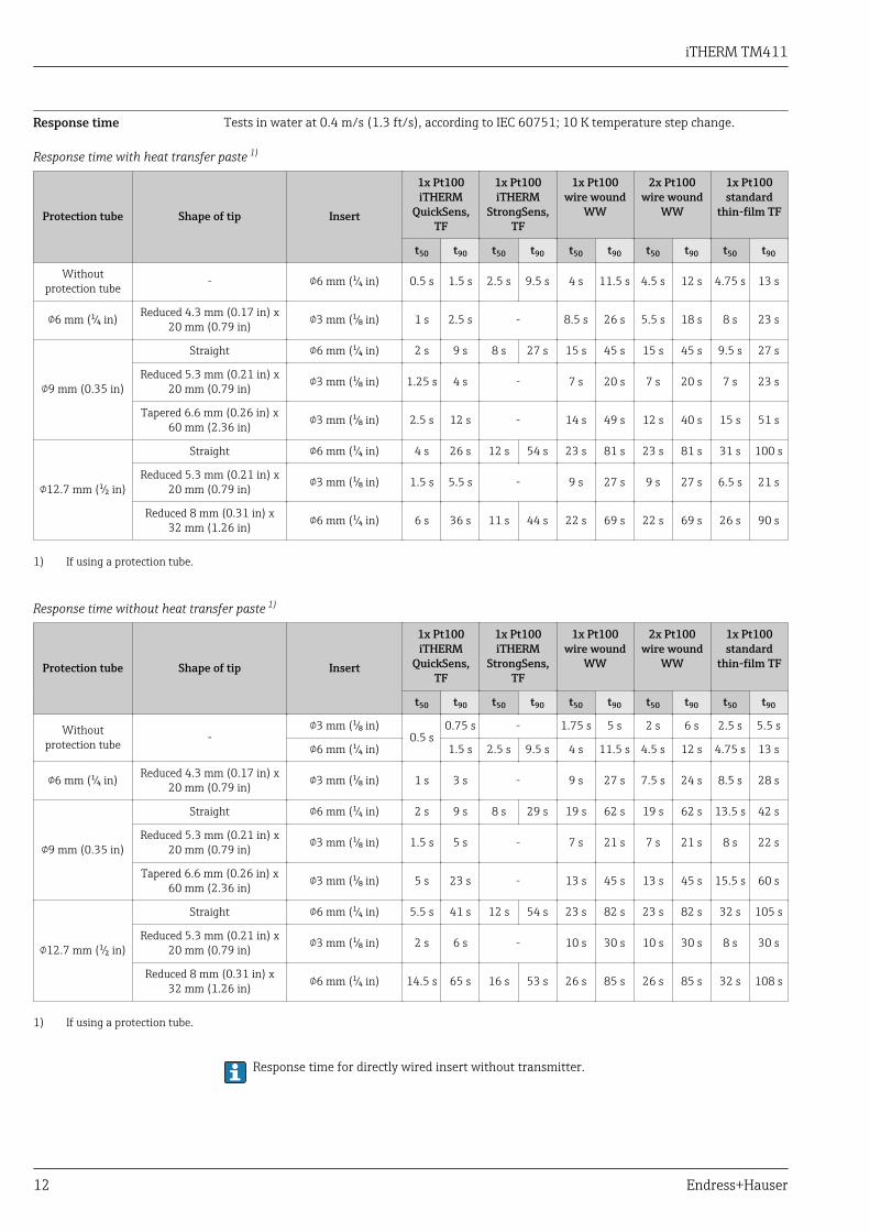
Response time Tests in water at 0.4 m/s (1.3 ft/s), according to IEC 60751; 10 K temperature step change.
Response time with heat transfer paste 1)
Protection tube Shape of tip Insert
1x Pt100iTHERM
QuickSens,TF
1x Pt100iTHERM
StrongSens,TF
1x Pt100wire wound
WW
2x Pt100wire wound
WW
1x Pt100standard
thin-film TF
t50 t90 t50 t90 t50 t90 t50 t90 t50 t90
Withoutprotection tube - 6 mm (¹⁄₄ in) 0.5 s 1.5 s 2.5 s 9.5 s 4 s 11.5 s 4.5 s 12 s 4.75 s 13 s
6 mm (¹⁄₄ in) Reduced 4.3 mm (0.17 in) x20 mm (0.79 in) 3 mm (¹⁄₈ in) 1 s 2.5 s - 8.5 s 26 s 5.5 s 18 s 8 s 23 s
9 mm (0.35 in)
Straight 6 mm (¹⁄₄ in) 2 s 9 s 8 s 27 s 15 s 45 s 15 s 45 s 9.5 s 27 s
Reduced 5.3 mm (0.21 in) x20 mm (0.79 in) 3 mm (¹⁄₈ in) 1.25 s 4 s - 7 s 20 s 7 s 20 s 7 s 23 s
Tapered 6.6 mm (0.26 in) x60 mm (2.36 in) 3 mm (¹⁄₈ in) 2.5 s 12 s - 14 s 49 s 12 s 40 s 15 s 51 s
12.7 mm (¹⁄₂ in)
Straight 6 mm (¹⁄₄ in) 4 s 26 s 12 s 54 s 23 s 81 s 23 s 81 s 31 s 100 s
Reduced 5.3 mm (0.21 in) x20 mm (0.79 in) 3 mm (¹⁄₈ in) 1.5 s 5.5 s - 9 s 27 s 9 s 27 s 6.5 s 21 s
Reduced 8 mm (0.31 in) x32 mm (1.26 in) 6 mm (¹⁄₄ in) 6 s 36 s 11 s 44 s 22 s 69 s 22 s 69 s 26 s 90 s
1) If using a protection tube.
Response time without heat transfer paste 1)
Protection tube Shape of tip Insert
1x Pt100iTHERM
QuickSens,TF
1x Pt100iTHERM
StrongSens,TF
1x Pt100wire wound
WW
2x Pt100wire wound
WW
1x Pt100standard
thin-film TF
t50 t90 t50 t90 t50 t90 t50 t90 t50 t90
Withoutprotection tube -
3 mm (¹⁄₈ in)0.5 s
0.75 s - 1.75 s 5 s 2 s 6 s 2.5 s 5.5 s
6 mm (¹⁄₄ in) 1.5 s 2.5 s 9.5 s 4 s 11.5 s 4.5 s 12 s 4.75 s 13 s
6 mm (¹⁄₄ in) Reduced 4.3 mm (0.17 in) x20 mm (0.79 in) 3 mm (¹⁄₈ in) 1 s 3 s - 9 s 27 s 7.5 s 24 s 8.5 s 28 s
9 mm (0.35 in)
Straight 6 mm (¹⁄₄ in) 2 s 9 s 8 s 29 s 19 s 62 s 19 s 62 s 13.5 s 42 s
Reduced 5.3 mm (0.21 in) x20 mm (0.79 in) 3 mm (¹⁄₈ in) 1.5 s 5 s - 7 s 21 s 7 s 21 s 8 s 22 s
Tapered 6.6 mm (0.26 in) x60 mm (2.36 in) 3 mm (¹⁄₈ in) 5 s 23 s - 13 s 45 s 13 s 45 s 15.5 s 60 s
12.7 mm (¹⁄₂ in)
Straight 6 mm (¹⁄₄ in) 5.5 s 41 s 12 s 54 s 23 s 82 s 23 s 82 s 32 s 105 s
Reduced 5.3 mm (0.21 in) x20 mm (0.79 in) 3 mm (¹⁄₈ in) 2 s 6 s - 10 s 30 s 10 s 30 s 8 s 30 s
Reduced 8 mm (0.31 in) x32 mm (1.26 in) 6 mm (¹⁄₄ in) 14.5 s 65 s 16 s 53 s 26 s 85 s 26 s 85 s 32 s 108 s
1) If using a protection tube.
Response time for directly wired insert without transmitter.

iTHERM TM411
Endress+Hauser 13
Calibration Calibration of thermometersCalibration involves comparing the measured values of a device under test (DUT) with those of amore precise calibration standard using a defined and reproducible measurement method. The aim isto determine the deviation of the DUT's measured values from the true value of the measuredvariable. Two different methods are used for thermometers:• Calibration at fixed-point temperatures, e.g. at the freezing point of water at 0 °C,• Calibration compared against a precise reference thermometer.The thermometer to be calibrated must display the fixed point temperature or the temperature ofthe reference thermometer as accurately as possible. Temperature-controlled calibration baths withvery homogeneous thermal values, or special calibration furnaces into which the DUT and thereference thermometer, where necessary, can project to a sufficient degree, are typically used forthermometer calibrations.
Evaluation of thermometersIf a calibration with an acceptable uncertainty of measurement and transferable measurementresults is not possible, Endress+Hauser offers customers a thermometer evaluation measurementservice, if technically feasible. This is the case when:• The process connections/flanges are too big or the immersion length (IL) is too short to allow the
DUT to be immersed sufficiently in the calibration bath or furnace (see the following table), or• Due to heat conduction along the thermometer tube, the resulting sensor temperature generally
deviates significantly from the actual bath/furnace temperature.The measured value of the DUT is determined using the maximum possible immersion depth and thespecific measuring conditions and measurement results are documented on an evaluation certificate.
Sensor transmitter matchingThe resistance/temperature curve of platinum resistance thermometers is standardized but inpractice it is rarely possible to keep to the values precisely over the entire operating temperaturerange. For this reason, platinum resistance sensors are divided into tolerance classes, such as ClassA, AA or B as per IEC 60751. These tolerance classes describe the maximum permissible deviation ofthe specific sensor characteristic curve from the standard curve, i.e. the maximum temperature-dependent characteristic error that is permitted. The conversion of measured sensor resistancevalues to temperatures in temperature transmitters or other meter electronics is often susceptible toconsiderable errors as the conversion is generally based on the standard characteristic curve.When using E+H temperature transmitters, this conversion error can be reduced significantly bysensor-transmitter matching:• Calibration at three temperatures at least and determination of the actual temperature sensor
characteristic curve,• Adjustment of the sensor-specific polynomial function using Calendar-van Dusen (CvD)
coefficients,• Configuration of the temperature transmitter with the sensor-specific CvD coefficients for
resistance/temperature conversion, and• another calibration of the reconfigured temperature transmitter with connected resistance
thermometer.Endress+Hauser offers its customers this kind of sensor-transmitter matching as a separate service.Furthermore, the sensor-specific polynomial coefficients of platinum resistance thermometers arealways provided on every Endress+Hauser calibration certificate where possible, e.g. at least threecalibration points, so that users themselves can also appropriately configure suitable temperaturetransmitters.
For the device, Endress+Hauser offers standard calibrations at a reference temperature of–80 to +600 °C (–112 to +1 112 °F) based on the ITS90 (International Temperature Scale).Calibrations in other temperature ranges are available from your Endress+Hauser sales center onrequest. Calibrations are traceable to national and international standards. The calibration certificateis referenced to the serial number of the device. Only the insert is calibrated.
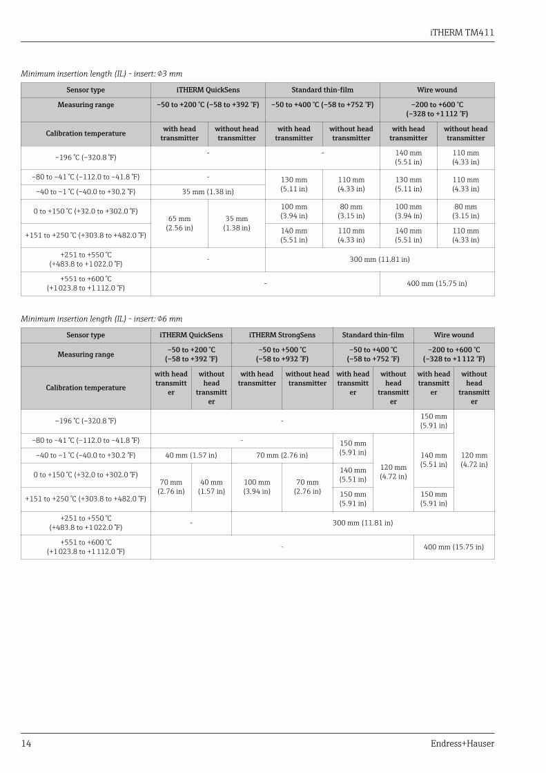
Minimum insertion length (IL) for inserts required to perform a correct calibration
The insert length IL is automatically calculated for every thermometer configuration in theEndress+Hauser Configurator+Temperature software application. The system also automaticallychecks whether the selected insert length suffices to perform a factory calibration. For furtherinformation, see the 'Accessories' section → 48
iTHERM TM411
14 Endress+Hauser
Minimum insertion length (IL) - insert: 3 mm
Sensor type iTHERM QuickSens Standard thin-film Wire wound
Measuring range –50 to +200 °C (–58 to +392 °F) –50 to +400 °C (–58 to +752 °F) –200 to +600 °C(–328 to +1 112 °F)
Calibration temperature with headtransmitter
without headtransmitter
with headtransmitter
without headtransmitter
with headtransmitter
without headtransmitter
–196 °C (–320.8 °F) - - 140 mm(5.51 in)
110 mm(4.33 in)
–80 to –41 °C (–112.0 to –41.8 °F) - 130 mm(5.11 in)
110 mm(4.33 in)
130 mm(5.11 in)
110 mm(4.33 in)–40 to –1 °C (–40.0 to +30.2 °F) 35 mm (1.38 in)
0 to +150 °C (+32.0 to +302.0 °F)65 mm
(2.56 in)35 mm
(1.38 in)
100 mm(3.94 in)
80 mm(3.15 in)
100 mm(3.94 in)
80 mm(3.15 in)
+151 to +250 °C (+303.8 to +482.0 °F) 140 mm(5.51 in)
110 mm(4.33 in)
140 mm(5.51 in)
110 mm(4.33 in)
+251 to +550 °C(+483.8 to +1 022.0 °F) - 300 mm (11.81 in)
+551 to +600 °C(+1 023.8 to +1 112.0 °F) - 400 mm (15.75 in)
Minimum insertion length (IL) - insert: 6 mm
Sensor type iTHERM QuickSens iTHERM StrongSens Standard thin-film Wire wound
Measuring range –50 to +200 °C(–58 to +392 °F)
–50 to +500 °C(–58 to +932 °F)
–50 to +400 °C(–58 to +752 °F)
–200 to +600 °C(–328 to +1 112 °F)
Calibration temperature
with headtransmitt
er
withouthead
transmitter
with headtransmitter
without headtransmitter
with headtransmitt
er
withouthead
transmitter
with headtransmitt
er
withouthead
transmitter
–196 °C (–320.8 °F) - 150 mm(5.91 in)
120 mm(4.72 in)
–80 to –41 °C (–112.0 to –41.8 °F) - 150 mm(5.91 in)
120 mm(4.72 in)
140 mm(5.51 in)
–40 to –1 °C (–40.0 to +30.2 °F) 40 mm (1.57 in) 70 mm (2.76 in)
0 to +150 °C (+32.0 to +302.0 °F)70 mm
(2.76 in)40 mm
(1.57 in)100 mm(3.94 in)
70 mm(2.76 in)
140 mm(5.51 in)
+151 to +250 °C (+303.8 to +482.0 °F) 150 mm(5.91 in)
150 mm(5.91 in)
+251 to +550 °C(+483.8 to +1 022.0 °F) - 300 mm (11.81 in)
+551 to +600 °C(+1 023.8 to +1 112.0 °F) - 400 mm (15.75 in)

iTHERM TM411
Endress+Hauser 15
IL IL*
ΔL
A0018625
2 Minimum insertion lengths for sensor calibration
IL Minimum insertion length for factory calibration or recalibration onsite without the iTHERM QuickNeckextension neck
IL* Minimum insertion length for recalibration onsite with the iTHERM QuickNeck extension neckΔL Additional length, depending on the calibration unit, if the insert cannot be fully immersed
• To check the actual accuracy rating of the thermometers installed, a cyclic calibration of theinstalled sensor is frequently performed. The insert is normally removed for comparison with aprecise reference thermometer in the calibration bath (see graphic, left part). A reproduciblecalibration requires the insert to have a minimum insertion length IL. If the insert is shorter thanthis minimum length, this reproducibility cannot be guaranteed.
• The iTHERM QuickNeck enables quick, tool-free removal of the insert for calibration purposes. Theentire upper part of the thermometer is released by turning the terminal head. The insert isremoved from the protection tube and directly immersed into the calibration bath (see graphic,right part). Make sure that the cable is long enough to be able to reach the mobile calibration bathwith the cable connected. If this is not possible for the calibration, it is advisable to use aconnector. → 33
Advantages of iTHERM QuickNeck:• Considerable time savings when recalibrating the device (up to 20 minutes per measuring point)• Wiring mistakes avoided when re-installing• Minimum plant downtime, thereby saving costs
The minimum immersion length is the length of the insert that is fully immersed in thecalibration bath. For a valid recalibration, the value selected for the length IL* must be at leastthe value of the previously defined minimum insertion lengths (IL) of the specific types ofinsert. For more detailed values, see the previous tables, values without head transmitter.If the calibration unit used does not allow the insert to be fully immersed as far as the bottomedge of the top part of the iTHERM QuickNeck, it might be necessary to add an additionallength (ΔL) to IL*. → 2, 15
Formulas for calculating the IL* when recalibrating onsite with iTHERM QuickNeck
Version, with M24x1.5 or NPT ½" thread to terminal head Formula
Protection tube diameter 6 mm (¹⁄₄ in) IL* = U + T + 5 mm (0.2 in)
Protection tube diameter 9 mm (0.35 in) IL* = U + T - 25 mm (0.98 in)
Protection tube diameter 12.7 mm (¹⁄₂ in) IL* = U + T + 5 mm (0.2 in)
Insulation resistance Insulation resistance ≥ 100 MΩ at ambient temperature.
Insulation resistance between the terminals and the outer jacket is measured with a minimumvoltage of 100 V DC.

iTHERM TM411
16 Endress+Hauser
Installation
Orientation No restrictions. However, self-draining in the process must be guaranteed. If there is an opening todetect leaks at the process connection, this opening must be at the lowest possible point.
Installation instructions The immersion length of the thermometer can influence the accuracy. If the immersion length is toosmall then errors in the measurement are caused by heat conduction via the process connection andthe container wall. If installing into a pipe then the immersion length should ideally be half of thepipe diameter.
• Installation possibilities: Pipes, tanks or other plant components• To minimize the error caused by heat conduction, a minimum immersion length is recommended
depending on the type of sensor used and the design of the insert. This immersion depthcorresponds to the minimum insertion length for the calibration.
• ATEX certification: Observe the installation instructions in the Ex documentation! → 49
U
≥ 3°
≥ 3°
1
2
3 4
A0008946
3 Installation examples
1, 2 Perpendicular to flow direction, installed at a min. angle of 3° to ensure self-draining3 On elbows4 Inclined installation in pipes with a small nominal diameterU Immersion length
In the case of pipes with a small nominal diameter, it is advisable for the tip of the thermometerto project well into the process so that it extends past the pipe axis. Installation at an angle (4)could be another solution. When determining the immersion length or installation depth all theparameters of the thermometer and of the medium to be measured must be taken into account(e.g. flow velocity, process pressure).
The use of iTHERM QuickNeck inserts is recommended for immersion lengths U <70 mm (27.6 in).

iTHERM TM411
Endress+Hauser 17
1 2
A0008947
4 Process connections for thermometer installation in pipes with small nominal diameters
1 Varivent® process connection type N for DN402 Corner-piece or T-piece (illustrated) for weld-in as per DIN 11865 / ASME BPE 2012
1 2 3 4
R0.4 R0.4
Sensor with
milk pipe
connectionSensor with Varivent
connection
Shaped
gasket
Companion
connectionO-ring
Groove
slip-on nut
Centering ring
Sealing
Companion
connection
Companion
connection
Gasket
(O-ring)
Welding boss
Leak detection hole
Vessel wall
A0011758-EN
5 Detailed installation instructions for hygiene-compliant installation
1 Sanitary connection according to DIN 11851, only in connection with EHEDG-certified and self-centeringsealing ring
2 Varivent® process connection for VARINLINE® housing3 Clamp according to ISO 28524 Liquiphant-M G1" process connection, horizontal installation

iTHERM TM411
18 Endress+Hauser
The counterpieces for the process connections and the seals or sealing rings are not included inthe scope of supply for the thermometer. Liquiphant M weld-in adapters with associated sealkits are available as accessories. → 44
Procedure in case of seal failure indicated by leak detection port:• Disassembling of the thermometer, validated cleaning procedure of thread and and sealing
ring groove• Replacement of the seal or sealing ring• CIP after re-assemblyIn the case of weld-in connections, exercise the necessary degree of care when performing thewelding work on the process side:• Suitable welding material• Flush-welded or with welding radius > 3.2 mm (0.13 in)• No recesses, folds or gaps• Honed and polished surface, Ra ≤ 0.76 µm (0.03 µin)As a general rule, the thermometers should be installed in such a way that does not impacttheir ability to be cleaned (the requirements of the 3-A® Standard must be observed). TheVarivent® and Liquiphant-M weld-in adapter and Ingold (+ weld-in adapter) connectionsenable flush-mounted installation.
Environment
Ambient temperature range Terminal head Temperature in °C (°F)
Without mounted head transmitter Depends on the terminal head used and the cable gland or fieldbusconnector, see 'Terminal heads' section → 31
With mounted head transmitter –40 to 85 °C (–40 to 185 °F)
With mounted head transmitter anddisplay
–20 to 70 °C (–4 to 158 °F)
Extension neck Temperature in °C (°F)
iTHERM QuickNeck –50 to +140 °C (–58 to +284 °F)
Storage temperature For information, see the ambient temperature.
Humidity Depends on the transmitter used. If Endress+Hauser iTEMP head transmitters are used:• Condensation permitted as per IEC 60 068-2-33• Max. rel. humidity: 95% as per IEC 60068-2-30
Climate class As per EN 60654-1, Class C
Degree of protection Max. IP69K, depending on the design (terminal head, connector, etc.)
Shock and vibrationresistance
The Endress+Hauser inserts meet the requirements of IEC 60751 which specify shock and vibrationresistance of 3g in the range from 10 to 500 Hz. The vibration resistance at the measuring pointdepends on the sensor type and design, see the following table:
Version Vibration resistance for the sensor tip
Pt100 (WW or TF) 30 m/s² (3g) 1)
iTHERM StrongSens Pt100 (TF)iTHERM QuickSens Pt100 (TF), version: 6 mm (0.24 in)
> 600 m/s² (60g)
1) Vibration resistance also applies for the quick-fastening iTHERM QuickNeck.

iTHERM TM411
Endress+Hauser 19
Electromagneticcompatibility (EMC)
Depends on the head transmitter used. For details see the Technical Information. → 49
Process
Process temperature range Depends on the type of sensor used, maximum –200 to +600 °C (–328 to +1 112 °F).
Thermal shock Thermal shock resistance in CIP/SIP process with a temperature increase from+5 to +130 °C (+41 to +266 °F) within 2 seconds.
Process pressure range The maximum possible process pressure depends on various influencing factors, such as the design,process connection and process temperature. For information on the maximum possible processpressures for the individual process connections, see the 'Process connection' section. → 35
It is possible to check the mechanical loading capacity as a function of the installation andprocess conditions online in the TW Sizing Module for protection tubes in the Endress+HauserApplicator software. See 'Accessories' section. → 48
Example of the permitted flow velocity depending on the immersion length and processmedium
The highest flow velocity tolerated by the thermometer diminishes with increasing insert immersionlength exposed to the stream of the fluid. In addition it is dependent on the diameter of thethermometer tip, on the kind of measuring medium, on the process temperature and on the processpressure. The following figures exemplify the maximum permitted flow velocities in water andsuperheated steam at a process pressure of 40 bar (580 PSI).
L (mm)
A
0
10
20
30
40
50
60
70
80
90
100 200 300 400 500
v (m/s)
B
0 4 8 12 16 20L (in)
0
30
65
100
130
160
200
230
260
290
v (ft/s)
A0008967
6 Permitted flow velocities, protection tube diameter 9 mm (0.35 in)
A Medium water at T = 50 °C (122 °F)B Medium superheated steam at T = 400 °C (752 °F)L Immersion length exposed to flowv Flow velocity
Medium - state ofaggregation
Gaseous or liquid (also with high viscosity, e.g. yogurt).

iTHERM TM411
20 Endress+Hauser
Mechanical construction
Design, dimensions All dimensions in mm (in). The design of the thermometer depends on the protection tube versionused:• Thermometer without a protection tube• Diameter 6 mm (¹⁄₄ in)• Diameter 9 mm (0.35 in)• Diameter 12.7 mm (¹⁄₂ in)• T-piece and corner-piece protection tube version as per DIN 11865 / ASME BPE 2012 for weld-in
Various dimensions, such as the immersion length U for example, are variable values and aretherefore indicated as items in the following dimensional drawings.
Variable dimensions:
Item Description
E Extension neck length, variable depending on the configuration or predefined for the version withiTHERM QuickNeck
IL Insertion length of insert
L Protection tube length (U+T)
B Protection tube base thickness: predefined, depends on protection tube version (see also theindividual table data)
T Length of protection tube shaft: variable or predefined, depends on protection tube version (seealso the individual table data)
U Immersion length: variable, depending on the configuration
X Variable for calculating the insertion length of the insert, depending on different screw-in lengthsin terminal head thread M24x1.5 or ½" NPT, see insert length calculation (IL) → 30
E
1 2
XX
E
15
(0
.6)
8 (
0.3
2)
NPT ½“M24x1.5
A0020889
7 Different screw-in lengths in terminal head thread for M24x1.5 and ½" NPT
1 Thread M24x1.5: X = 11 mm (0.43 in)2 Thread ½" NPT: X = 26 mm (1.02 in) or with TA30S terminal head = 31 mm (1.22 in)
ØID Insert diameter 6 mm (¹⁄₄ in) or 3 mm (¹⁄₈ in)
iTHERM TM411
Endress+Hauser 21
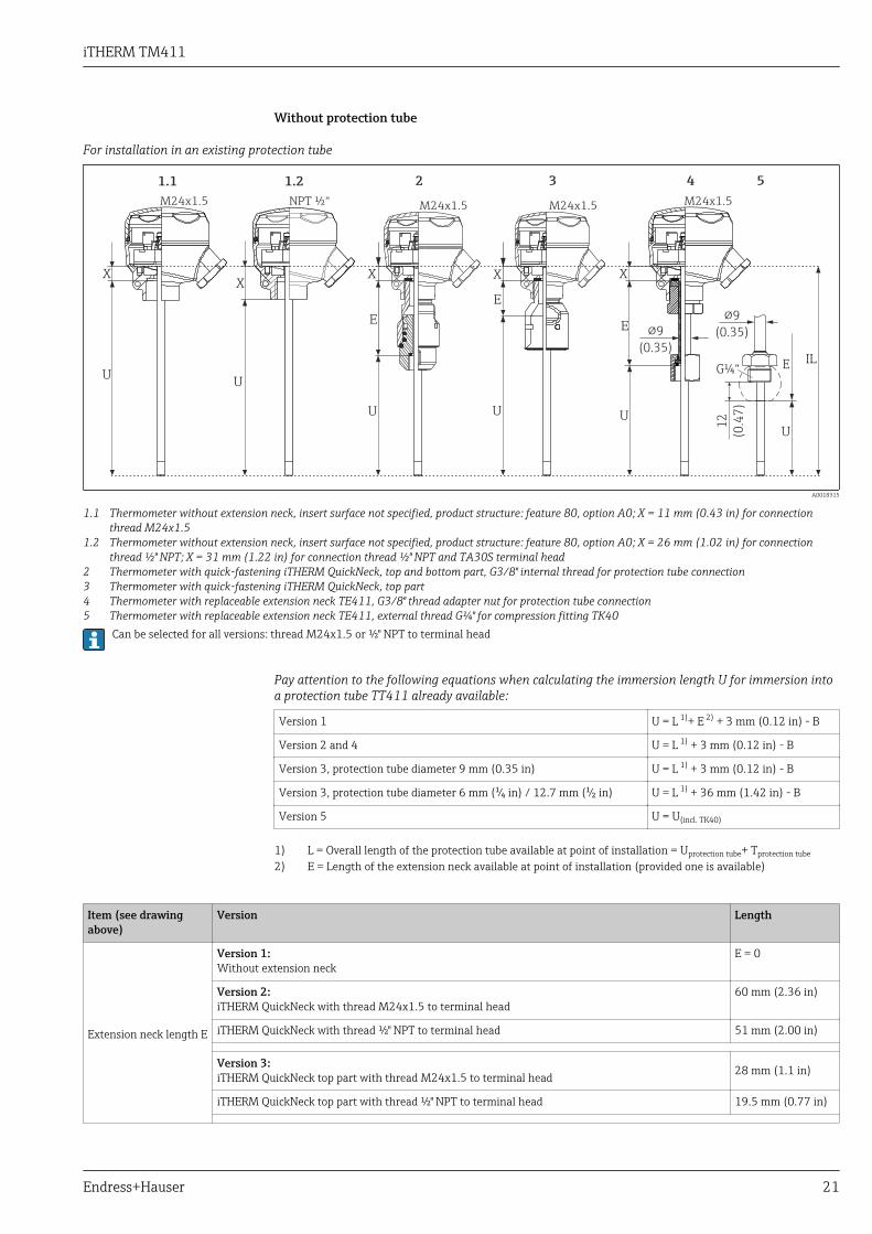
Without protection tube
For installation in an existing protection tube
IL
U
E
1.1 2 3
U
4 5
X
!9
(0.35)!9
(0.35)
G¼“ E
U
X
U
E
X
12
(0.4
7)
U
X
E
1.2
U
X
M24x1.5 M24x1.5 M24x1.5 M24x1.5NPT ½“
A0018315
1.1 Thermometer without extension neck, insert surface not specified, product structure: feature 80, option A0; X = 11 mm (0.43 in) for connectionthread M24x1.5
1.2 Thermometer without extension neck, insert surface not specified, product structure: feature 80, option A0; X = 26 mm (1.02 in) for connectionthread ½" NPT; X = 31 mm (1.22 in) for connection thread ½" NPT and TA30S terminal head
2 Thermometer with quick-fastening iTHERM QuickNeck, top and bottom part, G3/8" internal thread for protection tube connection3 Thermometer with quick-fastening iTHERM QuickNeck, top part4 Thermometer with replaceable extension neck TE411, G3/8" thread adapter nut for protection tube connection5 Thermometer with replaceable extension neck TE411, external thread G¼" for compression fitting TK40
Can be selected for all versions: thread M24x1.5 or ½" NPT to terminal head
Pay attention to the following equations when calculating the immersion length U for immersion intoa protection tube TT411 already available:
Version 1 U = L 1)+ E 2) + 3 mm (0.12 in) - B
Version 2 and 4 U = L 1) + 3 mm (0.12 in) - B
Version 3, protection tube diameter 9 mm (0.35 in) U = L 1) + 3 mm (0.12 in) - B
Version 3, protection tube diameter 6 mm (¹⁄₄ in) / 12.7 mm (¹⁄₂ in) U = L 1) + 36 mm (1.42 in) - B
Version 5 U = U(incl. TK40)
1) L = Overall length of the protection tube available at point of installation = Uprotection tube+ Tprotection tube
2) E = Length of the extension neck available at point of installation (provided one is available)
Item (see drawingabove)
Version Length
Extension neck length E
Version 1:Without extension neck
E = 0
Version 2:iTHERM QuickNeck with thread M24x1.5 to terminal head
60 mm (2.36 in)
iTHERM QuickNeck with thread ½" NPT to terminal head 51 mm (2.00 in)
Version 3:iTHERM QuickNeck top part with thread M24x1.5 to terminal head 28 mm (1.1 in)
iTHERM QuickNeck top part with thread ½" NPT to terminal head 19.5 mm (0.77 in)

iTHERM TM411
22 Endress+Hauser
Item (see drawingabove)
Version Length
Version 4: with replaceable extension neck, G3/8" thread adapter nut for protection tube connectionVariable, dependingon theconfiguration
Version 5: With replaceable extension neck and external thread G¼" for compression fitting TK40,with thread M24x1.5 or ½" NPT to terminal head 70 mm (2.76 in)
Immersion length U Independent of the versionVariable, dependingon theconfiguration
Variable length X• Connection thread M24x1.5• Connection thread ½" NPT• Connection thread ½" NPT and terminal head TA30S
IL = U+E+X11 mm (0.43 in)26 mm (1.02 in)31 mm (1.22 in)
With compression fitting TK40 as process connection, insert in direct contact with the process
!9
(0.35)
U
M24x1.5
X
U
X
G¼“
2
IL
M4x1
!44 (1.73)!33 (1.3)
!6
(¼)
3
!6
(¼)
!6
(¼)
U
X
1
!6
(¼)
4
NPT ½“
E =
70
(2
.56
)
X
8 (
0.3
2)
!9
(0.35)
G¼“
!6
(¼)
E =
70
(2
.56
)
5
U
A0017700
1 Movable compression fitting TK40 - variably fixable immersion length U, only connection thread M24x1.52 Without compression fitting for use if compression fitting is available at point of installation, insert with polished surface - product structure: feature
80, option A1 or A3 - only connection thread M24x1.53 Compression fitting TK40 fixed by extension neck - fixed immersion length U, connection thread M24x1.54 Compression fitting TK40 fixed by extension neck - fixed immersion length U, connection thread ½" NPT5 Insert, for example with mounted head transmitter
Item Version Length
Extension neck lengthE Extension neck 9 mm (0.35 in) 70 mm (2.76 in)
Immersion length U Independent of the versionVariable, dependingon theconfiguration
Variable length X • Versions 1 and 2: Without extension neck, connection thread M24x1.5• Version 3: With extension neck, connection thread M24x1.5• Version 4: With extension neck, connection thread ½" NPT• With extension neck and TA30S terminal head
IL = U+XIL = U+E+XIL = U+E+XIL = U+E+X
37 mm (1.46 in)11 mm (0.43 in)26 mm (1.02 in)31 mm (1.22 in)

iTHERM TM411
Endress+Hauser 23
With protection tube diameter 6 mm (¹⁄₄ in)
U
T
!9
(0.35)
!6 (0.24)
E
X
G3/8“
T
E
X
M24x1.5
U
1 2 3 4 5 6 7 8 9 10
NPT ½“
L L
36
(
1.4
2)
A0017790
1 Thermometer with replaceable extension neck TE411 and process connection as clamp version2 Without process connection3 Process connection version as spherical compression fitting TK404 Process connection version as metal sealing system M12x15 Process connection version as metal sealing system G½"6 Process connection version as cylindrical weld-in adapter 12 x 40 mm7 Process connection version as cylindrical weld-in adapter 30 x 40 mm8 Process connection version as spherical-cylindrical weld-in adapter 30 x 40 mm9 Process connection version as spherical weld-in adapter 25 x mm10 Thermometer with quick-fastening iTHERM QuickNeck and process connection as sanitary connection
according to DIN 11851
• Replaceable extension neck or quick-fastening iTHERM QuickNeck• Thread M24x1.5 or ½" NPT to terminal head• G3/8" thread for protection tube connection
Item Version Length
Extension neck length E
Replaceable extension neck 9 mm (0.35 in)Variable, dependingon theconfiguration
iTHERM QuickNeck with thread M24x1.5 to terminal head 60 mm (2.36 in)
iTHERM QuickNeck with thread ½" NPT to terminal head 51 mm (2.00 in)
Length of protection tubeshaft T 1)
Metal sealing system M12x1 46 mm (1.81 in)
Metal sealing system G½" 60 mm (2.36 in)
Tri-clamp (0.5"-0.75") 24 mm (0.94 in)
Microclamp (DN8-18) 23 mm (0.91 in)
Clamp DN12 according to ISO 2852 24 mm (0.94 in)
Clamp DN25/DN40 according to ISO 2852 21 mm (0.83 in)
Sanitary connection DN25/DN32/DN40 according to DIN11851
29 mm (1.14 in)
Spherical-cylindrical weld-in adapter 59 mm (2.32 in)
Cylindrical weld-in adapter 12 mm (0.47 in) 55 mm (2.17 in)
iTHERM TM411
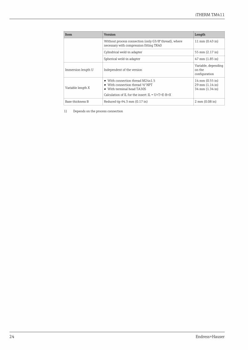
24 Endress+Hauser
Item Version Length
Without process connection (only G3/8" thread), wherenecessary with compression fitting TK40
11 mm (0.43 in)
Cylindrical weld-in adapter 55 mm (2.17 in)
Spherical weld-in adapter 47 mm (1.85 in)
Immersion length U Independent of the versionVariable, dependingon theconfiguration
Variable length X
• With connection thread M24x1.5• With connection thread ½" NPT• With terminal head TA30S
Calculation of IL for the insert: IL = U+T+E-B+X
14 mm (0.55 in)29 mm (1.14 in)34 mm (1.34 in)
Base thickness B Reduced tip 4.3 mm (0.17 in) 2 mm (0.08 in)
1) Depends on the process connection

iTHERM TM411
Endress+Hauser 25
With protection tube diameter 9 mm (0.35 in)
Extension neck not replaceable, but can be separated with the option of the quick-fastening iTHERM QuickNeck.
U
!9
(0.35)
T
E
X
U
T
X
1 2
!9 (0.35)
B
B
!15 (0.6)
3 4 5 6 7 8
149 10 11 12 13
M24x1.5
NPT ½“
L
L
A0017761
1 Thermometer without replaceable extension neck, connection thread M24x1.5, process connection as clamp version2 Process connection version as cylindrical weld-in adapter 30 x 40 mm3 Process connection version as spherical-cylindrical weld-in adapter 30 x 40 mm4 Process connection version as spherical weld-in adapter 25 x mm5 Process connection version as sanitary connection according to DIN 118516 Process connection version as aseptic pipe union according to DIN 11864-1 Form A7 Process connection version as metal sealing system G½"8 Process connection version as thread according to ISO 228 for Liquiphant weld-in adapter9 Process connection version APV Inline10 Process connection version Varivent®
11 Process connection version Ingold connection12 Process connection to SMS 114713 Process connection version Neumo Biocontrol14 Thermometer with quick-fastening iTHERM QuickNeck and process connection, as clamp version for example
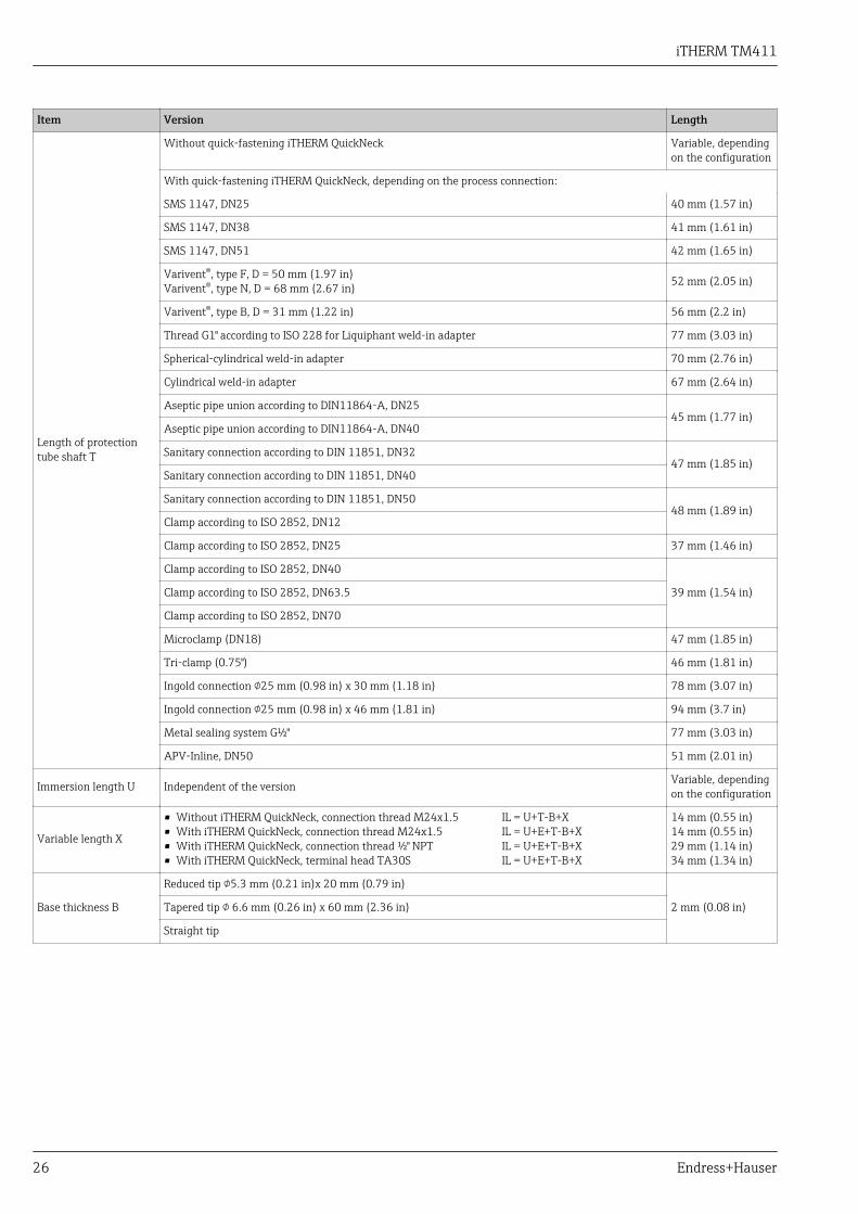
Item Version Length
Extension neck lengthE
Without quick-fastening iTHERM QuickNeck 0
With quick-fastening iTHERM QuickNeck• With thread M24x1.5 to terminal head• With thread ½" NPT to terminal head
• 28 mm (1.1 in)• 19.5 mm (0.8 in)
iTHERM TM411
26 Endress+Hauser
Item Version Length
Length of protectiontube shaft T
Without quick-fastening iTHERM QuickNeck Variable, dependingon the configuration
With quick-fastening iTHERM QuickNeck, depending on the process connection:
SMS 1147, DN25 40 mm (1.57 in)
SMS 1147, DN38 41 mm (1.61 in)
SMS 1147, DN51 42 mm (1.65 in)
Varivent®, type F, D = 50 mm (1.97 in)Varivent®, type N, D = 68 mm (2.67 in) 52 mm (2.05 in)
Varivent®, type B, D = 31 mm (1.22 in) 56 mm (2.2 in)
Thread G1" according to ISO 228 for Liquiphant weld-in adapter 77 mm (3.03 in)
Spherical-cylindrical weld-in adapter 70 mm (2.76 in)
Cylindrical weld-in adapter 67 mm (2.64 in)
Aseptic pipe union according to DIN11864-A, DN2545 mm (1.77 in)
Aseptic pipe union according to DIN11864-A, DN40
Sanitary connection according to DIN 11851, DN3247 mm (1.85 in)
Sanitary connection according to DIN 11851, DN40
Sanitary connection according to DIN 11851, DN5048 mm (1.89 in)
Clamp according to ISO 2852, DN12
Clamp according to ISO 2852, DN25 37 mm (1.46 in)
Clamp according to ISO 2852, DN40
39 mm (1.54 in)Clamp according to ISO 2852, DN63.5
Clamp according to ISO 2852, DN70
Microclamp (DN18) 47 mm (1.85 in)
Tri-clamp (0.75") 46 mm (1.81 in)
Ingold connection 25 mm (0.98 in) x 30 mm (1.18 in) 78 mm (3.07 in)
Ingold connection 25 mm (0.98 in) x 46 mm (1.81 in) 94 mm (3.7 in)
Metal sealing system G½" 77 mm (3.03 in)
APV-Inline, DN50 51 mm (2.01 in)
Immersion length U Independent of the version Variable, dependingon the configuration
Variable length X
• Without iTHERM QuickNeck, connection thread M24x1.5• With iTHERM QuickNeck, connection thread M24x1.5• With iTHERM QuickNeck, connection thread ½" NPT• With iTHERM QuickNeck, terminal head TA30S
IL = U+T-B+XIL = U+E+T-B+XIL = U+E+T-B+XIL = U+E+T-B+X
14 mm (0.55 in)14 mm (0.55 in)29 mm (1.14 in)34 mm (1.34 in)
Base thickness B
Reduced tip 5.3 mm (0.21 in)x 20 mm (0.79 in)
2 mm (0.08 in)Tapered tip 6.6 mm (0.26 in) x 60 mm (2.36 in)
Straight tip

iTHERM TM411
Endress+Hauser 27
With protection tube diameter 12.7 mm (¹⁄₂ in)
U
!9
(0.35)
T
E
B
!12.7
(0.5)
X
E
X
B
T
U
321 4 5 6 7
M24x1.5 NPT ½“
L L
36
(
1.4
2)
A0018313
1 Thermometer with replaceable extension neck TE411 and process connection as clamp version2 Process connection version as cylindrical weld-in adapter x 12.7 (0.5 mm)3 Process connection version as spherical weld-in adapter 25 x mm4 Process connection version as sanitary connection according to DIN 118515 Thread according to ISO 228 for Liquiphant weld-in adapter6 Process connection version Varivent®
7 Thermometer with quick-fastening iTHERM QuickNeck and process connection, as clamp version for example
• Replaceable extension neck or quick-fastening iTHERM QuickNeck• G3/8" thread for protection tube connection• Protection tube made from solid bar stock drilled for L ≤ 200 mm (7.87 in)• Welded protection tube for L > 200 mm (7.87 in)
Item Version Length
Extension neck length E
Replaceable extension neck, 9 mm (0.35 in) Variable, depending onthe configuration
iTHERM QuickNeck with thread M24x1.5 toterminal head
60 mm (2.36 in)
iTHERM QuickNeck with thread ½" NPT to terminalhead
51 mm (2 in)
Length of protection tubeshaft T
Weld-in adapter, cylindrical, 12.7 mm (0.5 in) 1) 12 mm (0.47 in)
All other process connections 65 mm (2.56 in)
Immersion length U Independent of the process connection Variable, depending onthe configuration
Variable length X
• With connection thread M24x1.5• With connection thread ½" NPT• With terminal head TA30S
Calculation of IL for the insert: IL = U+T+E-B+X
14 mm (0.55 in)29 mm (1.14 in)34 mm (1.34 in)
Base thickness B
Reduced tip 5.3 mm (0.21 in)x 20 mm (0.79 in) 2 mm (0.079 in)
Reduced tip 8 mm (0.31 in)x 32 mm (1.26 in) 4 mm (0.16 in)
Straight tip 6 mm (0.24 in)
1) See diagram for version 2
iTHERM TM411
28 Endress+Hauser
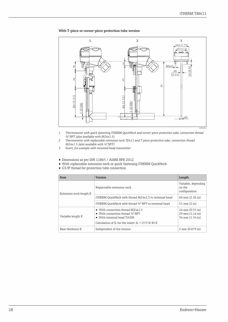
With T-piece or corner-piece protection tube version
2 (
0.0
8)
2 (
0.0
8)
84
(3
.31
)
E
X
IL
84
(3
.31
)
E
X
1 2
M4x1
Ø44 (1.73)
Ø33 (1.3)
Ø6
(0.24) 10
(0
.4)
ØID
3
A0018314
1 Thermometer with quick-fastening iTHERM QuickNeck and corner-piece protection tube, connection thread½" NPT (also available with M24x1.5)
2 Thermometer with replaceable extension neck TE411 and T-piece protection tube, connection threadM24x1.5 (also available with ½" NPT)
3 Insert, for example with mounted head transmitter
• Dimensions as per DIN 11865 / ASME BPE 2012• With replaceable extension neck or quick-fastening iTHERM QuickNeck• G3/8" thread for protection tube connection
Item Version Length
Extension neck length E
Replaceable extension neckVariable, dependingon theconfiguration
iTHERM QuickNeck with thread M24x1.5 to terminal head 60 mm (2.36 in)
iTHERM QuickNeck with thread ½" NPT to terminal head 51 mm (2 in)
Variable length X
• With connection thread M24x1.5• With connection thread ½" NPT• With terminal head TA30S
Calculation of IL for the insert: IL = U+T+E-B+X
14 mm (0.55 in)29 mm (1.14 in)34 mm (1.34 in)
Base thickness B Independent of the version 2 mm (0.079 in)
iTHERM TM411
Endress+Hauser 29
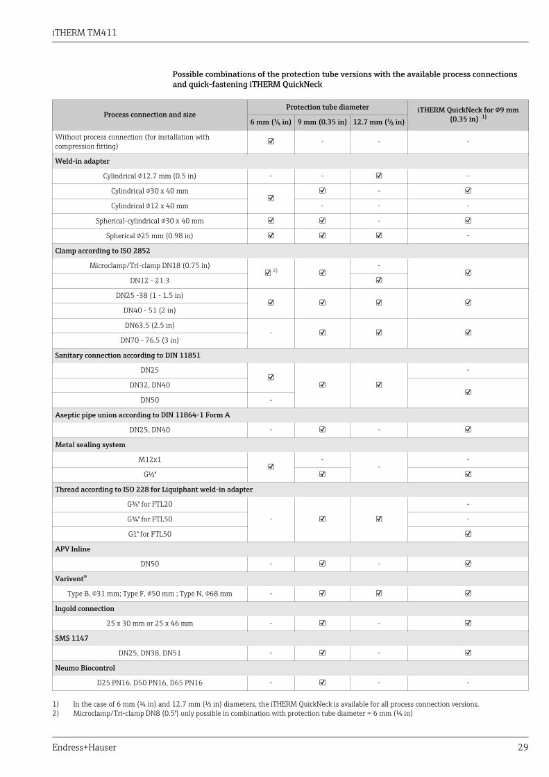
Possible combinations of the protection tube versions with the available process connectionsand quick-fastening iTHERM QuickNeck
Process connection and sizeProtection tube diameter iTHERM QuickNeck for 9 mm
(0.35 in) 1)6 mm (¹⁄₄ in) 9 mm (0.35 in) 12.7 mm (¹⁄₂ in)
Without process connection (for installation withcompression fitting) - - -
Weld-in adapter
Cylindrical 12.7 mm (0.5 in) - - -
Cylindrical 30 x 40 mm
-
Cylindrical 12 x 40 mm - - -
Spherical-cylindrical 30 x 40 mm -
Spherical 25 mm (0.98 in) -
Clamp according to ISO 2852
Microclamp/Tri-clamp DN18 (0.75 in) 2)
-
DN12 - 21.3
DN25 -38 (1 - 1.5 in)
DN40 - 51 (2 in)
DN63.5 (2.5 in)-
DN70 - 76.5 (3 in)
Sanitary connection according to DIN 11851
DN25
-
DN32, DN40
DN50 -
Aseptic pipe union according to DIN 11864-1 Form A
DN25, DN40 - -
Metal sealing system
M12x1
--
-
G½"
Thread according to ISO 228 for Liquiphant weld-in adapter
G¾" for FTL20
-
-
G¾" for FTL50 -
G1" for FTL50
APV Inline
DN50 - -
Varivent®
Type B, 31 mm; Type F, 50 mm ; Type N, 68 mm -
Ingold connection
25 x 30 mm or 25 x 46 mm - -
SMS 1147
DN25, DN38, DN51 - -
Neumo Biocontrol
D25 PN16, D50 PN16, D65 PN16 - - -
1) In the case of 6 mm (¼ in) and 12.7 mm (½ in) diameters, the iTHERM QuickNeck is available for all process connection versions.2) Microclamp/Tri-clamp DN8 (0.5") only possible in combination with protection tube diameter = 6 mm (¼ in)

iTHERM TM411
30 Endress+Hauser
Insert Depending on the application, iTHERM TS111 inserts with different RTD sensors are available forthe thermometer:
Sensor Standard thin-film iTHERM StrongSens iTHERM QuickSens 1) Wire wound
Sensor design;connection method
1x Pt100, 3- or 4-wire,mineral insulated
1x Pt100, 3- or 4-wire,mineral insulated
1x Pt100, 3- or 4-wire
• 6 mm (¹⁄₄ in), mineralinsulated
• 3 mm (¹⁄₈ in), tefloninsulated
1x Pt100, 3- or 4-wire, mineral
insulated
2x Pt100, 3-wire,mineral insulated
Vibrationresistance of the
insert tipUp to 3g Enhanced vibration
resistance > 60g• 3 mm (¹⁄₈ in) up to 3g• 6 mm (¹⁄₄ in) > 60g Up to 3g
Measuring range;accuracy class
–50 to +400 °C(–58 to +752 °F), Class A
or AA
–50 to +500 °C(–58 to +932 °F), Class A
or AA
–50 to +200 °C(–58 to +392 °F), Class A
or AA
–200 to +600 °C (–328 to +1 112 °F), ClassA or AA
Diameter 3 mm (¹⁄₈ in),6 mm (¹⁄₄ in) 6 mm (¹⁄₄ in) 3 mm (¹⁄₈ in), 6 mm (¹⁄₄ in)
1) Recommended for immersion lengths U < 70 mm (2.76 in)
The iTHERM TS111 insert is available as a spare part. The insertion length (IL) depends on theimmersion length of the protection tube (U), the length of the extension neck (E), the thickness ofthe base (B), the length of the protection tube shaft (L) and the variable length (X). The insertionlength (IL) must be taken into consideration when replacing the unit. Formulas for calculating IL→ 20.
For more information on the deployed insert iTHERM TS111 with enhanced vibrationresistance and fast-response sensor, see the Technical Information (TI01014T/09/).Spare parts currently available for your product can be found online at:http://www.products.endress.com/spareparts_consumables, product root: TM411. Alwaysquote the serial number of the device when ordering spare parts! The insertion length IL isautomatically calculated using the serial number.
Weight 0.5 to 2.5 kg (1 to 5.5 lbs) for standard options.
Material Extension neck and thermowell, insert, process connection.
The temperatures for continuous operation specified in the following table are only intended asreference values for use of the various materials in air and without any significant compressive load.The maximum operating temperatures can be reduced considerably in cases where abnormalconditions such as high mechanical load occur or in aggressive media.
Designation Short form
Recommendedmax. temperaturefor continuous usein air
Properties
AISI 316L(complies with1.4404or 1.4435)
X2CrNiMo17-13-2,X2CrNiMo18-14-3
650 °C (1 202 °F) 1) • Austenitic, stainless steel• High corrosion resistance in general• Particularly high corrosion resistance in
chlorine-based and acidic, non-oxidizingatmospheres through the addition ofmolybdenum (e.g. phosphoric andsulfuric acids, acetic and tartaric acidswith a low concentration)
• Increased resistance to intergranularcorrosion and pitting
1.4435+316L, Deltaferrite < 1%
With regard to analytical limits, the specifications of both materials (1.4435 and 316L)are met simultaneously. In addition, the Delta ferrite content of the wetted parts islimited to <1% - including the welding seams (following Basel Standard II)
1) Can be used to a limited extent up to 800 °C (1472 °F) for low compressive loads and in non-corrosivemedia. Contact your Endress+Hauser sales team for further information.

iTHERM TM411
Endress+Hauser 31
Surface roughness Values for wetted surfaces: 1)
Standard surface Ra ≤ 0.76 µm (0.03 µin)
Finely honed surface 2) Ra ≤ 0.38 µm (0.015 µin)
Finely honed surface and electropolished Ra ≤ 0.38 µm (0.015 µin)+ electropolished
1) Exception: Inside welding seams of the T- and corner pieces2) Not compliant with ASME BPE
Terminal heads All terminal heads have an internal shape and size in accordance with DIN EN 50446, flat face and athermometer connection with a M24x1.5 or ½" NPT thread. All dimensions in mm (in). The samplecable glands in the diagrams correspond to M20x1.5 connections with non-Ex polyamide cableglands. Specifications without head transmitter installed. For ambient temperatures with headtransmitter installed, see the 'Environment' section. → 18
As a special feature, Endress+Hauser offers terminal heads with optimized terminal accessibility foreasy installation and maintenance.
TA30A Specification
107.5 (4.23)
68
.5 (
2.7
)
28
(1.1)78 (3.1)
15
.5 (
0.6
)
A0009820
• Available with one or two cable entries• Protection class: IP66/68 (NEMA Type 4x encl.)• Temperature: –50 to +150 °C (–58 to +302 °F) without cable
gland• Material: aluminum, polyester powder coated
Seals: silicone• Threaded cable entry: G ½", ½" NPT and M20x1.5;• Protection armature connection: M24x1.5• Head color: blue, RAL 5012• Cap color: gray, RAL 7035• Weight: 330 g (11.64 oz)• Ground terminal, internal and external• With 3-A® symbol
TA30A with display window Specification
107.5 (4.23)
91
.6 (
3.6
1)
28
(1.1)78 (3.1)
15
.5 (
0.6
)
A0009821
• Available with one or two cable entries• Protection class: IP66/68 (NEMA Type 4x encl.)• Temperature: –50 to +150 °C (–58 to +302 °F) without cable
gland• Material: aluminum, polyester powder coated
Seals: silicone• Threaded cable entry: G ½", ½" NPT and M20x1.5• Protection armature connection: M24x1.5• Head color: blue, RAL 5012
Cap color: gray, RAL 7035• Weight: 420 g (14.81 oz)• with TID10 display• Ground terminal, internal and external• 3-A® marked

iTHERM TM411
32 Endress+Hauser
TA30D Specification
107.5 (4.23)
11
0 (
4.3
)
28
(1.1)78 (3.1)
15
.5 (
0.6
)
A0009822
• Available with one or two cable entries• Protection class: IP66/68 (NEMA Type 4x encl.)• Temperature: –50 to +150 °C (–58 to +302 °F) without cable
gland• Material: aluminum, polyester powder coated
Seals: silicone• Threaded cable entry: G ½", ½" NPT and M20x1.5• Protection armature connection: M24x1.5• Two head transmitters can be mounted. In the standard
version, one transmitter is mounted in the terminal headcover and an additional terminal block is installed directlyon the insert.
• Head color: blue, RAL 5012• Cap color: gray, RAL 7035• Weight: 390 g (13.75 oz)• Ground terminal, internal and external• With 3-A® symbol
TA30P Specification
!83 (3.3)
11
4 (
4.5
)
85 (3.4)
41
.5 (
1.6
3)
28
(1.1)
A0023477
• Protection class: IP65• Max. temperature: –40 to +120 °C (–40 to +248 °F)• Material: polyamide (PA), antistatic
Seals: silicone• Threaded cable entry: M20x1.5• Protection armature connection: M24x1.5• Two head transmitters can be mounted. In the standard
version, one transmitter is mounted in the terminal headcover and an additional terminal block is installed directly onthe insert.
• Head and cap color: black• Weight: 135 g (4.8 oz)• Types of protection for use in hazardous locations: Intrinsic
Safety (G Ex ia)• Ground terminal: only internal via auxiliary clamp
TA30R (optionally with display window incover)
Specification
64 (2.52)
96 (3.8)
64 (2.52)
71 (
2.8
)
25 (1)
96 (
3.8
)*
A0017145
* Dimensions of version with display windowin cover
• Degree of protection - standard version: IP69K (NEMA Type4x encl.)Degree of protection - version with display window: IP66/68(NEMA Type 4x encl.)
• Temperature: –50 to +130 °C (–58 to +266 °F) without cablegland
• Material: stainless steel 316L, abrasive-blasted or polishedSeals: silicone, optional EPDM for applications free frompaint-wetting impairment substancesDisplay window: polycarbonate (PC)
• Cable entry thread ½" NPT and M20x1.5• Weight
– Standard version: 360 g (12.7 oz)– Version with display window: 460 g (16.23 oz)
• Display window in cover optionally for head transmitter withdisplay TID10
• Protection armature connection: M24x1.5 or ½" NPT• Ground terminal: internal in standard version; external
terminal optionally available• With 3-A® symbol
iTHERM TM411
Endress+Hauser 33
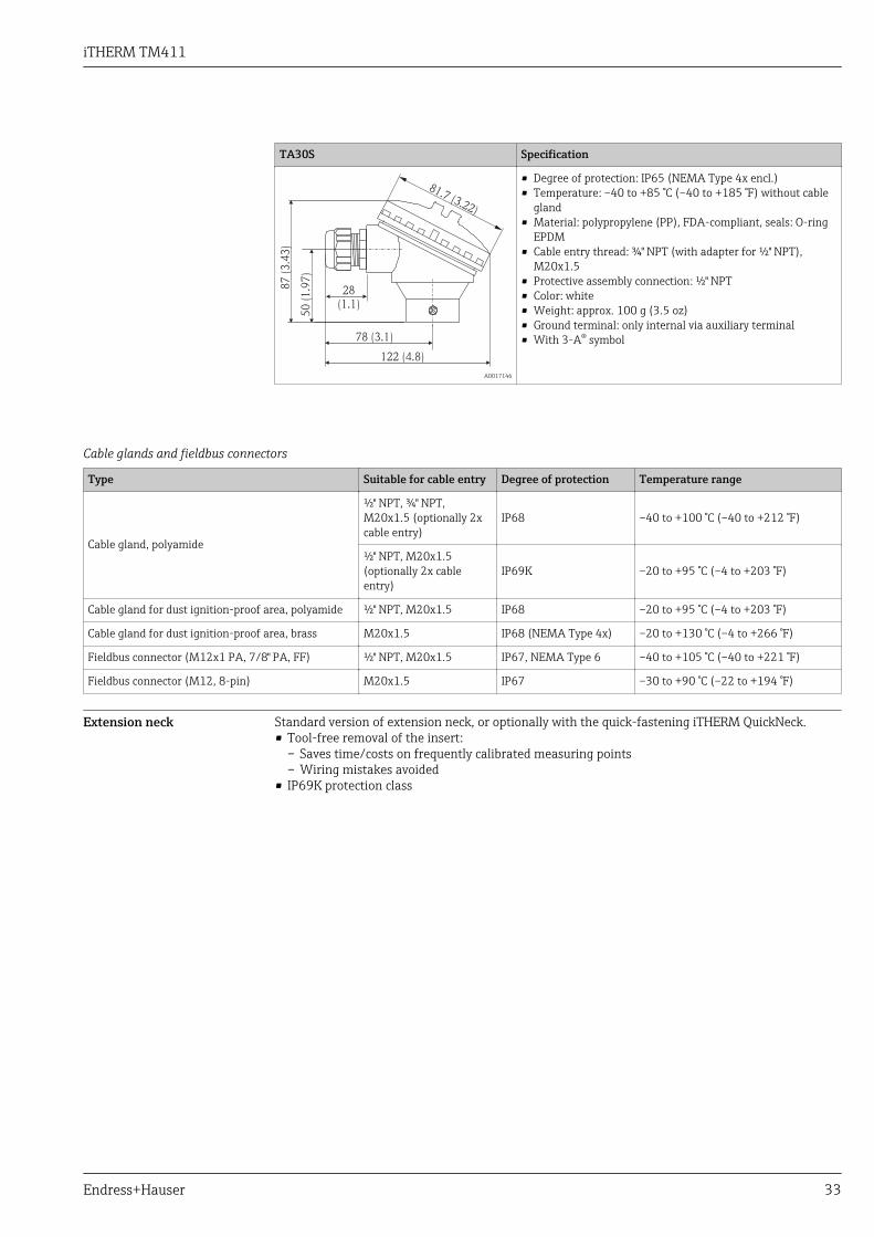
TA30S Specification
122 (4.8)
28
(1.1)
78 (3.1)
50 (
1.9
7)
87 (
3.4
3)
81.7 (3.22)
A0017146
• Degree of protection: IP65 (NEMA Type 4x encl.)• Temperature: –40 to +85 °C (–40 to +185 °F) without cable
gland• Material: polypropylene (PP), FDA-compliant, seals: O-ring
EPDM• Cable entry thread: ¾" NPT (with adapter for ½" NPT),
M20x1.5• Protective assembly connection: ½" NPT• Color: white• Weight: approx. 100 g (3.5 oz)• Ground terminal: only internal via auxiliary terminal• With 3-A® symbol
Cable glands and fieldbus connectors
Type Suitable for cable entry Degree of protection Temperature range
Cable gland, polyamide
½" NPT, ¾" NPT,M20x1.5 (optionally 2xcable entry)
IP68 –40 to +100 °C (–40 to +212 °F)
½" NPT, M20x1.5(optionally 2x cableentry)
IP69K –20 to +95 °C (–4 to +203 °F)
Cable gland for dust ignition-proof area, polyamide ½" NPT, M20x1.5 IP68 –20 to +95 °C (–4 to +203 °F)
Cable gland for dust ignition-proof area, brass M20x1.5 IP68 (NEMA Type 4x) –20 to +130 °C (–4 to +266 °F)
Fieldbus connector (M12x1 PA, 7/8" PA, FF) ½" NPT, M20x1.5 IP67, NEMA Type 6 –40 to +105 °C (–40 to +221 °F)
Fieldbus connector (M12, 8-pin) M20x1.5 IP67 –30 to +90 °C (–22 to +194 °F)
Extension neck Standard version of extension neck, or optionally with the quick-fastening iTHERM QuickNeck.• Tool-free removal of the insert:
– Saves time/costs on frequently calibrated measuring points– Wiring mistakes avoided
• IP69K protection class

iTHERM TM411
34 Endress+Hauser
!9
(0.35)
G¼“
G3/8"
E
E8
(0.3
2)
E
E8
(0
.32
)
E =
60
(2
.36
)
E =
51
(2
)8
(0
.32
)
G3/8"
!9
(0.35)
M24x1.5 M24x1.5M24x1.5NPT ½“ NPT ½“ NPT ½“
1 2 3
15
(0
.6)
15
(0
.6)
15
(0
.6)
E =
28
(1.1
)
E =
19
.5
(0.7
7)
8 (
0.3
2)
M24x1.5NPT ½“
4
15
(0
.6)
A0017953
8 Dimensions of extension neck type TE411, different versions, each with M24x1.5 or NPT ½" thread to theterminal head
1 With G¼" external thread for compression fitting TK40, → 41 with 3-A® symbol2 With G3/8" thread adapter nut for thermowell version: 6 mm (¼ in), 12.7 mm (0.5 in) and T-piece and
corner-piece thermowell versions3 Quick-fastening iTHERM QuickNeck for thermowell version: 6 mm (¼ in), 12.7 mm (0.5 in) and T-piece
and corner-piece thermowell versions4 Quick-fastening iTHERM QuickNeck - top part, for installation in an existing thermowell with iTHERM
QuickNeck
iTHERM TM411
Endress+Hauser 35
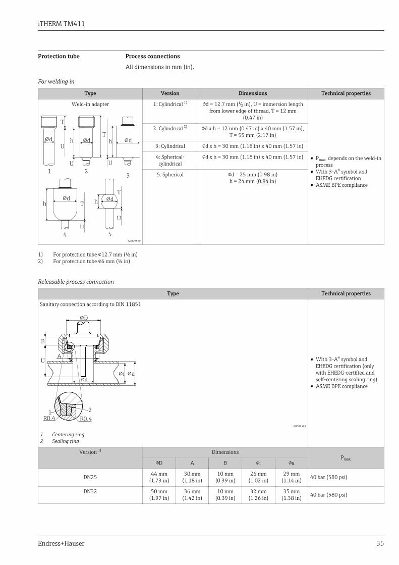
Protection tube Process connections
All dimensions in mm (in).
For welding in
Type Version Dimensions Technical properties
Weld-in adapter
!d
U
U
U
h !d !dh
!dh
!d
1 23
4 5
U
T
U
T
T
T
h
A0009569
1: Cylindrical 1) d = 12.7 mm (¹⁄₂ in), U = immersion lengthfrom lower edge of thread, T = 12 mm
(0.47 in)
• Pmax. depends on the weld-inprocess
• With 3-A® symbol andEHEDG certification
• ASME BPE compliance
2: Cylindrical 2) d x h = 12 mm (0.47 in) x 40 mm (1.57 in),T = 55 mm (2.17 in)
3: Cylindrical d x h = 30 mm (1.18 in) x 40 mm (1.57 in)
4: Spherical-cylindrical
d x h = 30 mm (1.18 in) x 40 mm (1.57 in)
5: Spherical d = 25 mm (0.98 in)h = 24 mm (0.94 in)
1) For protection tube 12.7 mm (½ in)2) For protection tube 6 mm (¼ in)
Releasable process connection
Type Technical properties
Sanitary connection according to DIN 11851
A
B
U
!d
!D
1 2
R0.4 R0.4
!i !a
A0009561
1 Centering ring2 Sealing ring
• With 3-A® symbol andEHEDG certification (onlywith EHEDG-certified andself-centering sealing ring).
• ASME BPE compliance
Version 1) DimensionsPmax.
D A B i a
DN25 44 mm(1.73 in)
30 mm(1.18 in)
10 mm(0.39 in)
26 mm(1.02 in)
29 mm(1.14 in) 40 bar (580 psi)
DN32 50 mm(1.97 in)
36 mm(1.42 in)
10 mm(0.39 in)
32 mm(1.26 in)
35 mm(1.38 in) 40 bar (580 psi)
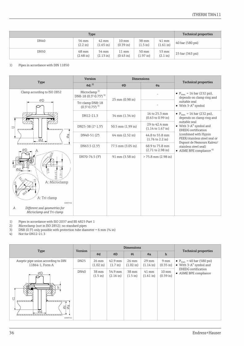
iTHERM TM411
36 Endress+Hauser
Type Technical properties
DN40 56 mm(2.2 in)
42 mm(1.65 in)
10 mm(0.39 in)
38 mm(1.5 in)
41 mm(1.61 in) 40 bar (580 psi)
DN50 68 mm(2.68 in)
54 mm(2.13 in)
11 mm(0.43 in)
50 mm(1.97 in)
53 mm(2.1 in) 25 bar (363 psi)
1) Pipes in accordance with DIN 11850
TypeVersion Dimensions
Technical propertiesd: 1) D a
Clamp according to ISO 2852
!D
U
!d
!a
!dU
!D
R0
.8
R0
.5
0.8
± 0
.1
2.1
6 ±
0.1
R1.2
R0.8
0.4 1
.6
A
A: Microclamp
A: Tri-clamp
A0009566
A Different seal geometries forMicroclamp and Tri-clamp
Microclamp 2)
DN8-18 (0.5"-0.75") 3)
25 mm (0.98 in)- • Pmax. = 16 bar (232 psi),
depends on clamp ring andsuitable seal
• With 3-A® symbolTri-clamp DN8-18
(0.5"-0.75") 3) -
DN12-21.3 34 mm (1.34 in) 16 to 25.3 mm(0.63 to 0.99 in)
• Pmax. = 16 bar (232 psi),depends on clamp ring andsuitable seal
• With 3-A® symbol andEHEDG certification(combined with HyjoinPEEK/stainless steel seal orDupont de Nemours Kalrez/stainless steel seal)
• ASME BPE compliance 4)
DN25-38 (1"-1.5") 50.5 mm (1.99 in) 29 to 42.4 mm(1.14 to 1.67 in)
DN40-51 (2") 64 mm (2.52 in) 44.8 to 55.8 mm(1.76 to 2.2 in)
DN63.5 (2.5") 77.5 mm (3.05 in) 68.9 to 75.8 mm(2.71 to 2.98 in)
DN70-76.5 (3") 91 mm (3.58 in) > 75.8 mm (2.98 in)
1) Pipes in accordance with ISO 2037 and BS 4825 Part 12) Microclamp (not in ISO 2852); no standard pipes3) DN8 (0.5") only possible with protection tube diameter = 6 mm (¼ in)4) Not for DN12-21.3
Type VersionDimensions
Technical propertiesd D i a h
Aseptic pipe union according to DIN11864-1, Form A
!D
h
U
!d
!i
!a
A0009562
DN25 26 mm(1.02 in)
42.9 mm(1.7 in)
26 mm(1.02 in)
29 mm(1.14 in)
9 mm(0.35 in)
• Pmax. = 40 bar (580 psi)• With 3-A® symbol and
EHEDG certification• ASME BPE complianceDN40 38 mm
(1.5 in)54.9 mm(2.16 in)
38 mm(1.5 in)
41 mm(1.61 in)
10 mm(0.39 in)

iTHERM TM411
Endress+Hauser 37
Type Version Technical properties
Metal sealing system
M12x1.5
U
14 (0.55)
22 (0.87)
M12
1.5x!1
0
(0.4
)
8 (0.3)
!6
(¼)
G3/8"
T = 46 (1.81)
20°
A0009574
G½"
U
14
(0.55)
37 (1.46)
G½”!1
8
(0.7
1)
8 (0.31)
!6
(¼
)
G3/8"
T = 60 (2.36)
22.5°
A0020856
Protection tube diameter6 mm (¼ in)
• Pmax. = 16 bar (232 psi)• EHEDG certified
Maximum torque =10 Nm (7.38 lbf ft)
-
U
14
(0.55)
37 (1.46)
G½”
"1
8 (
0.7
1)
8 (0.31)
"9
(0
.35
)
T
45°
A0009571
Protection tube diameter9 mm (0.35 in)
• Pmax. = 16 bar (232 psi)• EHEDG certified
Maximum torque =10 Nm (7.38 lbf ft)
Type Version GDimensions
Technical propertiesL1 threadlength
A 1 (SW/AF)
Thread according to ISO 228 (forLiquiphant weld-in adapter)
U
L1
1
GA
A0009572
G¾" for FTL20
adapter 16 mm
(0.63 in) 25.5 mm (1 in) 32• Pmax. = 25 bar (362 psi) at
max. 150 °C (302 °F)• Pmax. = 40 bar (580 psi) at
max. 100 °C (212 °F)• With 3-A® symbol and
EHEDG certification• ASME BPE compliance
G¾" for FTL50
adapter
G1" for FTL50adapter
18.6 mm(0.73 in)
29.5 mm(1.16 in) 41
Type VersionDimensions
Technical propertiesd A B M h
APV Inline
h
!d
M
!A
!B
U
A0018435
DN50 69 mm(2.72 in)
99.5 mm(3.92 in)
82 mm(3.23 in) 2xM8 19 mm
(0.75 in)
• Pmax. = 25 bar (362 psi)• With 3-A® symbol and
EHEDG certification• ASME BPE compliance
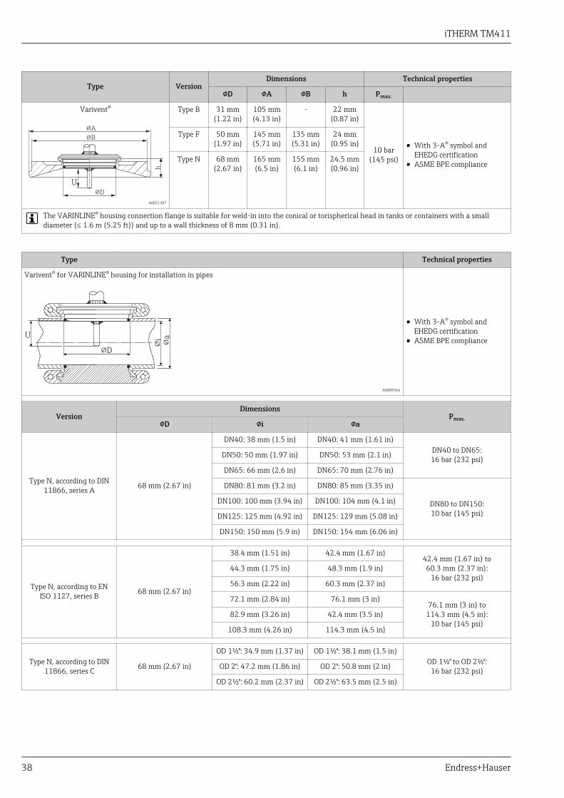
iTHERM TM411
38 Endress+Hauser
Type VersionDimensions Technical properties
D A B h Pmax.
Varivent®
U!D
!B
!A
h
A0021307
Type B 31 mm(1.22 in)
105 mm(4.13 in)
- 22 mm(0.87 in)
10 bar(145 psi)
• With 3-A® symbol andEHEDG certification
• ASME BPE compliance
Type F 50 mm(1.97 in)
145 mm(5.71 in)
135 mm(5.31 in)
24 mm(0.95 in)
Type N 68 mm(2.67 in)
165 mm(6.5 in)
155 mm(6.1 in)
24.5 mm(0.96 in)
The VARINLINE® housing connection flange is suitable for weld-in into the conical or torispherical head in tanks or containers with a smalldiameter (≤ 1.6 m (5.25 ft)) and up to a wall thickness of 8 mm (0.31 in).
Type Technical properties
Varivent® for VARINLINE® housing for installation in pipes
U
!D
!i
!a
A0009564
• With 3-A® symbol andEHEDG certification
• ASME BPE compliance
VersionDimensions
Pmax.D i a
Type N, according to DIN11866, series A 68 mm (2.67 in)
DN40: 38 mm (1.5 in) DN40: 41 mm (1.61 in)DN40 to DN65:16 bar (232 psi)DN50: 50 mm (1.97 in) DN50: 53 mm (2.1 in)
DN65: 66 mm (2.6 in) DN65: 70 mm (2.76 in)
DN80: 81 mm (3.2 in) DN80: 85 mm (3.35 in)
DN80 to DN150:10 bar (145 psi)
DN100: 100 mm (3.94 in) DN100: 104 mm (4.1 in)
DN125: 125 mm (4.92 in) DN125: 129 mm (5.08 in)
DN150: 150 mm (5.9 in) DN150: 154 mm (6.06 in)
Type N, according to ENISO 1127, series B 68 mm (2.67 in)
38.4 mm (1.51 in) 42.4 mm (1.67 in)42.4 mm (1.67 in) to60.3 mm (2.37 in):
16 bar (232 psi)44.3 mm (1.75 in) 48.3 mm (1.9 in)
56.3 mm (2.22 in) 60.3 mm (2.37 in)
72.1 mm (2.84 in) 76.1 mm (3 in)76.1 mm (3 in) to
114.3 mm (4.5 in):10 bar (145 psi)
82.9 mm (3.26 in) 42.4 mm (3.5 in)
108.3 mm (4.26 in) 114.3 mm (4.5 in)
Type N, according to DIN11866, series C 68 mm (2.67 in)
OD 1½": 34.9 mm (1.37 in) OD 1½": 38.1 mm (1.5 in)OD 1½" to OD 2½":
16 bar (232 psi)OD 2": 47.2 mm (1.86 in) OD 2": 50.8 mm (2 in)
OD 2½": 60.2 mm (2.37 in) OD 2½": 63.5 mm (2.5 in)

iTHERM TM411
Endress+Hauser 39
Type Technical properties
Type N, according to DIN11866, series C 68 mm (2.67 in)
OD 3": 73 mm (2.87 in) OD 3": 76.2 mm (3 in)OD 3" to OD 4": 10 bar (145 psi)
OD 4": 97.6 mm (3.84 in) OD 4": 101.6 mm (4 in)
Due to the small immersion length U, the use of iTHERM QuickSens inserts is recommended.
Type Version, dimensions D x h Technical properties
Ingold connection
U
1.5
(0.0
6)
4
(0.1
6)
h!D
R1¼“
A0009573
25 mm (0.98 in) x 30 mm (1.18 in)
Pmax. = 25 bar (362 psi)
25 mm (0.98 in) x 46 mm (1.81 in)
Type VersionDimensions
Technical propertiesD A h
SMS 1147 DN25 32 mm(1.26 in)
35.5 mm(1.4 in)
7 mm (0.28 in)
Pmax. = 6 bar (87 psi)
U
1
23
h
!D
!A
A0009568
1 Thread adapter nut2 Sealing ring3 Counterpart connection
DN38 48 mm(1.89 in)
55 mm(2.17 in)
8 mm (0.31 in)
DN51 60 mm(2.36 in)
65 mm(2.56 in)
9 mm (0.35 in)
The counterpart connection must fit the sealing ring and fix it in place.
Type VersionDimensions
Technical propertiesA B D d h
Neumo Biocontrol
U
h
!D!A
M
!B
A0018497
D25
PN16
64 mm(2.52 in)
50 mm(1.97 in)
30.4 mm(1.2 in)
7 mm(0.28 in)
20 mm(0.79 in)
• Pmax. = 16 bar (232 psi)• With 3-A® symbol
D50
PN16
90 mm(3.54 in)
70 mm(2.76 in)
49.9 mm(1.97 in)
9 mm(0.35 in)
27 mm(1.06 in)
D65PN25
120 mm(4.72 in)
95 mm(3.74 in)
67.9 mm(2.67 in)
11 mm(0.43 in)
Due to the small immersion length U, the use of iTHERM QuickSens inserts is generallyrecommended for T-piece/corner-piece process connections according to DIN 11865.
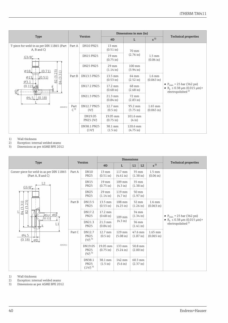
iTHERM TM411
40 Endress+Hauser
Type VersionDimensions in mm (in)
Technical propertiesD L s 1)
T-piece for weld-in as per DIN 11865 (PartA, B and C)
!D
82
(3
.23
)
!3.1
(0.12)
!4.5 (0.18)
G3/8”8
4 (
3.3
1)
L
!13 (0.51)
!18 (0.71)
s
A0018552
Part A DN10 PN25 13 mm(0.51 in) 70 mm
(2.76 in) 1.5 mm(0.06 in)
• Pmax. = 25 bar (362 psi)• Ra ≤ 0.38 µm (0.015 µin)+
electropolished 2)
DN15 PN25 19 mm(0.75 in)
DN25 PN25 29 mm(1.14 in)
100 mm(3.94 in)
Part B DN13.5 PN25 13.5 mm(0.53 in)
64 mm(2.52 in)
1.6 mm(0.063 in)
DN17.2 PN25 17.2 mm(0.68 in)
68 mm(2.68 in)
DN21.3 PN25 21.3 mm(0.84 in)
72 mm(2.83 in)
PartC 3)
DN12.7 PN25(½")
12.7 mm(0.5 in)
95.2 mm(3.75 in)
1.65 mm(0.065 in)
DN19.05PN25 (¾")
19.05 mm(0.75 in)
101.6 mm(4 in)
DN38.1 PN25(1½")
38.1 mm(1.5 in)
120.6 mm(4.75 in)
1) Wall thickness2) Exception: internal welded seams3) Dimensions as per ASME BPE 2012
Type VersionDimensions
Technical propertiesD L L1 L2 s 1)
Corner-piece for weld-in as per DIN 11865(Part A, B and C)
82
(3
.23
)
!4.5
(0.18)
!3.1
(0.12)
G3/8”
84
(3
.31
)
!D
!DL
L1
L2
s
A0018561
Part A DN10PN25
13 mm(0.51 in)
117 mm(4.61 in)
35 mm(1.38 in)
1.5 mm(0.06 in)
• Pmax. = 25 bar (362 psi)• Ra ≤ 0.38 µm (0.015 µin)+
electropolished 2)
DN15PN25
19 mm(0.75 in)
109 mm(4.3 in)
35 mm(1.38 in)
DN25PN25
29 mm(1.14 in)
119 mm(4.7 in)
50 mm(1.97 in)
Part B DN13.5PN25
13.5 mm(0.53 in)
108 mm(4.25 in)
32 mm(1.26 in)
1.6 mm(0.063 in)
DN17.2PN25
17.2 mm(0.68 in) 109 mm
(4.3 in)
34 mm(1.34 in)
DN21.3PN25
21.3 mm(0.84 in)
36 mm(1.41 in)
Part C DN12.7PN25(½") 3)
12.7 mm(0.5 in)
129 mm(5.08 in)
47.6 mm(1.87 in)
1.65 mm(0.065 in)
DN19.05PN25(¾") 3)
19.05 mm(0.75 in)
133 mm(5.24 in)
50.8 mm(2.00 in)
DN38.1PN25
(1½") 3)
38.1 mm(1.5 in)
142 mm(5.6 in)
60.3 mm(2.37 in)
1) Wall thickness2) Exception: internal welded seams3) Dimensions as per ASME BPE 2012
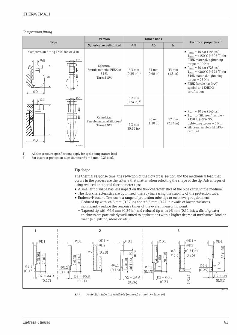
iTHERM TM411
Endress+Hauser 41
Compression fitting
TypeVersion Dimensions
Technical properties 1)
Spherical or cylindrical di D h
Compression fitting TK40 for weld-in
!di
!D
!di
!D
hh
!d
!d
A0017582
Spherical
Ferrule material PEEK or316L
Thread G¼"
6.3 mm(0.25 in) 2)
25 mm(0.98 in)
33 mm(1.3 in)
• Pmax. = 10 bar (145 psi),Tmax. = +150 °C (+302 °F) forPEEK material, tighteningtorque = 10 Nm
• Pmax. = 50 bar (725 psi),Tmax. = +200 °C (+392 °F) for316L material, tighteningtorque = 25 Nm
• PEEK ferrule has 3-A®
symbol and EHEDGcertification
CylindricalFerrule material Silopren®
Thread G½"
6.2 mm(0.24 in) 2)
30 mm(1.18 in)
57 mm(2.24 in)
• Pmax. = 10 bar (145 psi)• Tmax. for Silopren® ferrule =
+150 °C (+302 °F),tightening torque = 5 Nm
• Silopren ferrule is EHEDG-certified
9.2 mm(0.36 in)
1) All the pressure specifications apply for cyclic temperature load2) For insert or protection tube diameter Ød = 6 mm (0.236 in).
Tip shape
The thermal response time, the reduction of the flow cross-section and the mechanical load thatoccurs in the process are the criteria that matter when selecting the shape of the tip. Advantages ofusing reduced or tapered thermometer tips:• A smaller tip shape has less impact on the flow characteristics of the pipe carrying the medium.• The flow characteristics are optimized, thereby increasing the stability of the protection tube.• Endress+Hauser offers users a range of protection tube tips to meet every requirement:
– Reduced tip with 4.3 mm (0.17 in) and 5.3 mm (0.21 in): walls of lower thicknesssignificantly reduce the response times of the overall measuring point.
– Tapered tip with 6.6 mm (0.26 in) and reduced tip with 8 mm (0.31 in): walls of greaterthickness are particularly well suited to applications with a higher degree of mechanical load orwear (e.g. pitting, abrasion etc.).
!7 (0.28)
2 (
0.0
8)
20
(0
.8)
D2 = !5.3
(0.21)
!3.2
(0.13)
2 (0
.08)
40
(1
.6)
20
(0.8
)
D2 = !6.6
(0.26)
!4.1
(0.16)
2 (0
.08)
20
(0
.8)
D2 = !5.3
(0.21)
!3.2
(0.13)
2
(0.0
8)
6 (
0.2
4)
D2 = !8
(0.31)
4
(1.6
)20
(0
.8)
D2 = !4.3
(0.17)
2 (
0.0
8)
2 31
!D1 !D1 !
!
D1 =
D2!D1 !D1 !D1
!3.3
(0.13)
!8 (0.31) /1
!6.6 (0.26) 32
(1
.26
)
!6.4
(0.25)
!
!
D1 =
D2
A0017174
9 Protection tube tips available (reduced, straight or tapered)
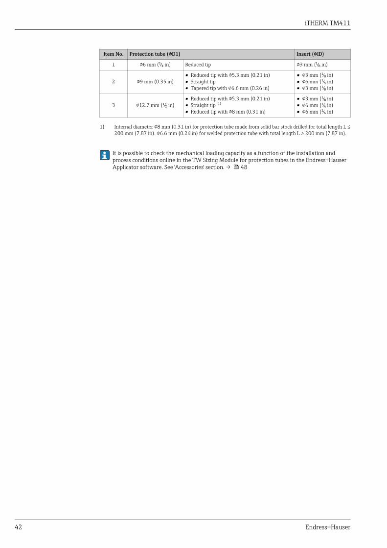
iTHERM TM411
42 Endress+Hauser
Item No. Protection tube (D1) Insert (ID)
1 6 mm (¹⁄₄ in) Reduced tip 3 mm (¹⁄₈ in)
2 9 mm (0.35 in)• Reduced tip with 5.3 mm (0.21 in)• Straight tip• Tapered tip with 6.6 mm (0.26 in)
• 3 mm (¹⁄₈ in)• 6 mm (¹⁄₄ in)• 3 mm (¹⁄₈ in)
3 12.7 mm (¹⁄₂ in)• Reduced tip with 5.3 mm (0.21 in)• Straight tip 1)
• Reduced tip with 8 mm (0.31 in)
• 3 mm (¹⁄₈ in)• 6 mm (¹⁄₄ in)• 6 mm (¹⁄₄ in)
1) Internal diameter 8 mm (0.31 in) for protection tube made from solid bar stock drilled for total length L ≤200 mm (7.87 in). 6.6 mm (0.26 in) for welded protection tube with total length L ≥ 200 mm (7.87 in).
It is possible to check the mechanical loading capacity as a function of the installation andprocess conditions online in the TW Sizing Module for protection tubes in the Endress+HauserApplicator software. See 'Accessories' section. → 48
iTHERM TM411
Endress+Hauser 43
Certificates and approvals
CE mark The measuring system meets the legal requirements of the EC Directives. Endress+Hauser confirmssuccessful testing of the device by affixing to it the CE mark.
Hygiene standard • EHEDG certification, type EL CLASS I. Permitted process connections in accordance with EHEDG,see 'Process connections' section → 35
• 3-A® authorization no. 1144, 3-A® sanitary standard 74-06. Permitted process connections inaccordance with 3-A®, see 'Process connections' section → 35
• ASME BPE, certificate of conformity can be ordered for indicated options• FDA-compliant• All product contact surfaces are produced without animal fats (TSE Certificate of Suitability)
Ex approval Information about currently available Ex versions (ATEX, FM, CSA, etc.) can be supplied by your E+HSales Center on request. All explosion protection data are given in separate documentation which isavailable upon request.
Other standards andguidelines
• EN 60079: ATEX certification for hazardous areas• IEC 60529: Degrees of protection provided by enclosures (IP code)• IEC 61010-1: Safety requirements for electrical equipment for measurement, control and
laboratory use• IEC 60751: Industrial platinum resistance thermometers• EN 50281-1-1: Electrical apparatus protected by enclosures• DIN 43772: Protection tubes• DIN EN 50446: Terminal heads• IEC 61326-1: Electromagnetic compatibility (electrical equipment for measurement, control and
laboratory use - EMC requirements)
Parts in contact with themedium
Parts of the thermometer in contact with the medium comply with the following Europeanregulations:• (EC) No. 1935/2004, Article 3, paragraph 1, Articles 5 and 17 on materials and articles intended
to come into contact with food.• (EC) No. 2023/2006 on good manufacturing practice for materials and articles intended to come
into contact with food.• (EC) No. 10/2011 on plastic materials and articles intended to come into contact with food.
Surface roughness • Free from oil and grease for O2 applications, optional• PWIS-free (PWIS = paint-wetting impairment substances as per DIL0301), optional
Material resistance Material resistance - including terminal heads - to the following cleaning agents/disinfectants fromthe company Ecolab: P3-topax 66, P3-topactive 200, P3-topactive 500 and P3-topactive OKTO aswell as demineralized water.
Material certification The material certificate 3.1 (according to standard EN 10204) can be requested separately. The"short form" certificate includes a simplified declaration with no enclosures of documents related tothe materials used in the construction of the single sensor and guarantees the traceability of thematerials through the identification number of the thermometer. The data related to the origin ofthe materials can subsequently be requested by the client if necessary.
Calibration The "Factory calibration" is carried out according to an internal procedure in a laboratory of Endress+Hauser accredited by the European Accreditation Organization (EA) to ISO/IEC 17025. Acalibration which is performed according to EA guidelines (SIT/Accredia) or (DKD/DAkkS) may berequested separately. The calibration is performed on the replaceable insert of the thermometer. Inthe case of thermometers without a replaceable insert, the entire thermometer - from the processconnection to the tip of the thermometer - is calibrated.

iTHERM TM411
44 Endress+Hauser
Protection tube testing andload capacity calculation
• Protection tube pressure tests are carried out in accordance with the specifications in DIN 43772.With regard to protection tubes with tapered or reduced tips that do not comply with thisstandard, these are tested using the pressure of corresponding straight protection tubes. Testsaccording to other specifications can be carried out on request. The liquid penetration test verifiesthat there are no cracks in the welded seams of the protection tube.
• EN1779 helium leak test, PMI test, concentricity test for drilled protection tubes, dye penetrationtest, TW welding, internal hydrostatic pressure, etc. each with inspection certificate
• Load capacity calculation for the protection tube as per DIN43772
Ordering informationDetailed ordering information is available from the following sources:• In the Product Configurator on the Endress+Hauser website: www.endress.com → Select your
country → Products → Select measuring technology, software or components → Select the product(picklists: measurement method, product family etc.) → Device support (right-hand column):Configure the selected product → The Product Configurator for the selected product opens.
• From your Endress+Hauser Sales Center: www.addresses.endress.comProduct Configurator - the tool for individual product configuration• Up-to-the-minute configuration data• Depending on the device: Direct input of measuring point-specific information such as
measuring range or operating language• Automatic verification of exclusion criteria• Automatic creation of the order code and its breakdown in PDF or Excel output format• Ability to order directly in the Endress+Hauser Online Shop
AccessoriesVarious accessories, which can be ordered with the device or subsequently from Endress+Hauser, areavailable for the device. Detailed information on the order code in question is available from yourlocal Endress+Hauser sales center or on the product page of the Endress+Hauser website:www.endress.com.

iTHERM TM411
Endress+Hauser 45
Device-specific accessories Accessories Description
Welding boss with sealing taper(metal - metal)
!30 (1.18)
16
(0
.63
)
34
(1
.34
)
15
(0
.6)
G½”
A0006621
M12x1.5
!7.6 (0.3)
!20 (0.8)
13
(0
.51
)
17
(0
.67
)
A0018236
Welding boss for G½" and M12x1.5 threadMetal-sealing; conicalMaterial of wetted parts: 316L/1.4435Max. process pressure 16 bar (232 PSI)
Order number:• 60021387 (G½")• 71190468 (M12x1.5)
Dummy plug
8
(0
.31
)
!18
(0.71)
G½”/
M12x1.5
37
(1
.46
)
AF22
A0009213-EN
Dummy plug for G½” or M12x1.5 conical metal-sealing welding bossMaterial: SS 316L/1.4435
Order number:• 60022519 (G½")• 60021194 (M12x1.5)
Weld-in adapter for Ingold processconnections
G 1¼”
50
(1
.97
)
A0008956
Material of wetted parts: 316L/1.4435Weight: 0.32 kg (0.7 lb)Order number: 60017887
O-ring seal set• Silicone O-ring in accordance with FDA CFR 21• Maximum temperature: 230 °C (446 °F)• Order number: 60018911
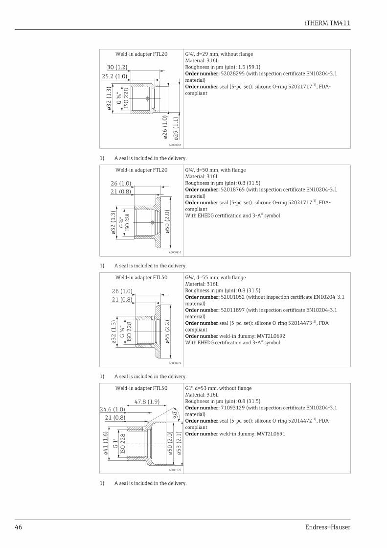
iTHERM TM411
46 Endress+Hauser
Weld-in adapter FTL20
ø2
6 (
1.0
)
25.2 (1.0)
ø2
9 (
1.1
)
30 (1.2)
G
ISO
22
8
¾“
ø3
2 (
1.3
)
A0008265
G¾", d=29 mm, without flangeMaterial: 316LRoughness in μm (μin): 1.5 (59.1)Order number: 52028295 (with inspection certificate EN10204-3.1material)Order number seal (5-pc. set): silicone O-ring 52021717 1), FDA-compliant
1) A seal is included in the delivery.
Weld-in adapter FTL20ø
50
(2
.0)
26 (1.0)
21 (0.8)
ø3
2 (
1.3
)
G ¾
“
ISO
22
8
A0008810
G¾", d=50 mm, with flangeMaterial: 316LRoughness in μm (μin): 0.8 (31.5)Order number: 52018765 (with inspection certificate EN10204-3.1material)Order number seal (5-pc. set): silicone O-ring 52021717 1), FDA-compliantWith EHEDG certification and 3-A® symbol
1) A seal is included in the delivery.
Weld-in adapter FTL50
26 (1.0)
ø5
5 (
2.2
)
21 (0.8)
ø3
2 (
1.3
)
G ¾
“
ISO
22
8
A0008274
G¾", d=55 mm, with flangeMaterial: 316LRoughness in μm (μin): 0.8 (31.5)Order number: 52001052 (without inspection certificate EN10204-3.1material)Order number: 52011897 (with inspection certificate EN10204-3.1material)Order number seal (5-pc. set): silicone O-ring 52014473 1), FDA-compliantOrder number weld-in dummy: MVT2L0692With EHEDG certification and 3-A® symbol
1) A seal is included in the delivery.
Weld-in adapter FTL50
ø5
0 (
2.0
)
ø5
3 (
2.1
)
47.8 (1.9)
24.6 (1.0)
30
°
21 (0.8)
ø4
1 (
1.6
)
G 1
"
ISO
22
8
A0011927
G1", d=53 mm, without flangeMaterial: 316LRoughness in μm (μin): 0.8 (31.5)Order number: 71093129 (with inspection certificate EN10204-3.1material)Order number seal (5-pc. set): silicone O-ring 52014472 1), FDA-compliantOrder number weld-in dummy: MVT2L0691
1) A seal is included in the delivery.

iTHERM TM411
Endress+Hauser 47
Weld-in adapter FTL50
ø4
1 (
1.6
)
G 1
"IS
O 2
28
ø6
0 (
2.4
)
29.6 (1.2)
24.6 (1.0)
A0008267
G1", d=60 mm, with flangeMaterial: 316LRoughness in μm (μin): 0.8 (31.5)Order number: 52001051 (without inspection certificate EN10204-3.1material)Order number: 52011896 (with inspection certificate EN10204-3.1material)Order number seal (5-pc. set): silicone O-ring 52014472 1), FDA-compliantOrder number weld-in dummy: MVT2L0691With EHEDG certification and 3-A® symbol
1) A seal is included in the delivery.
Weld-in adapter FTL50
26
(1
.02
)
5 (
0.2
)
ø65 (2.56)
A0008272
G1", can be alignedMaterial: 316LRoughness in μm (μin): 0.8 (31.5)Order number: 52001221 (without inspection certificate EN10204-3.1material)Order number: 52011898 (with inspection certificate EN10204-3.1material)Order number seal (5-pc. set): silicone O-ring 52014424 1), FDA-compliantOrder number weld-in dummy: M40167
1) A seal is included in the delivery.
Flexible handle cap to cover theQuickNeck bottom part
!D
20
(0
.79
)
35
(1
.38
)
A0027201
Diameter D: 24 to 26 mm (0.94 to 1.02 in)Material: Thermoplastic polyolefin - elastomer (TPE), free fromplasticizersMaximum temperature: +150 °C (+302 °F)Order number: 71275424
Maximum process pressure for the weld-in adapters:• 25 bar (362 PSI) at maximum 150 °C (302 °F)• 40 bar (580 PSI) at maximum 100 °C (212 °F)For more information on the weld-in adapters FTL20, FTL50, see Technical Information(TI00426F/00).
Communication-specificaccessories
Configuration kit TXU10 Configuration kit for PC-programmable transmitter with setup software andinterface cable for PC with USB portOrder code: TXU10-xx

iTHERM TM411
48 Endress+Hauser
Commubox FXA195HART
For intrinsically safe HART communication with FieldCare via the USB interface.
For details, see "Technical Information" TI00404F
Commubox FXA291 Connects Endress+Hauser field devices with a CDI interface (= Endress+HauserCommon Data Interface) and the USB port of a computer or laptop.
For details, see "Technical Information" TI00405C
HART Loop ConverterHMX50
Is used to evaluate and convert dynamic HART process variables to analog currentsignals or limit values.
For details, see "Technical Information" TI00429F and Operating InstructionsBA00371F
Wireless HART adapterSWA70
Is used for the wireless connection of field devices.The WirelessHART adapter can be easily integrated into field devices and existinginfrastructures, offers data protection and transmission safety and can be operatedin parallel with other wireless networks with minimum cabling complexity.
For details, see Operating Instructions BA061S
Fieldgate FXA320 Gateway for the remote monitoring of connected 4-20 mA measuring devices via aWeb browser.
For details, see "Technical Information" TI00025S and Operating InstructionsBA00053S
Fieldgate FXA520 Gateway for the remote diagnostics and remote configuration of connected HARTmeasuring devices via a Web browser.
For details, see "Technical Information" TI00025S and Operating InstructionsBA00051S
Field Xpert SFX100 Compact, flexible and robust industry handheld terminal for remote configurationand for obtaining measured values via the HART current output (4-20 mA).
For details, see Operating Instructions BA00060S
Service-specific accessories Accessories Description
Applicator Software for selecting and sizing Endress+Hauser measuring devices:• Calculation of all the necessary data for identifying the optimum measuring
device: e.g. pressure loss, accuracy or process connections.• Graphic illustration of the calculation results
Administration, documentation and access to all project-related data andparameters over the entire life cycle of a project.
Applicator is available:• Via the Internet: https://wapps.endress.com/applicator• On CD-ROM for local PC installation.
Configurator+temperature Software for selecting and configuring the product depending on the measuringtask, supported by graphics. Includes a comprehensive knowledge database andcalculation tools:• For temperature competence• Quick and easy design and sizing of temperature measuring points• Ideal measuring point design and sizing to suit the processes and needs of a wide
range of industries
The Configurator is available:On request from your Endress+Hauser sales office on a CD-ROM for local PCinstallation.
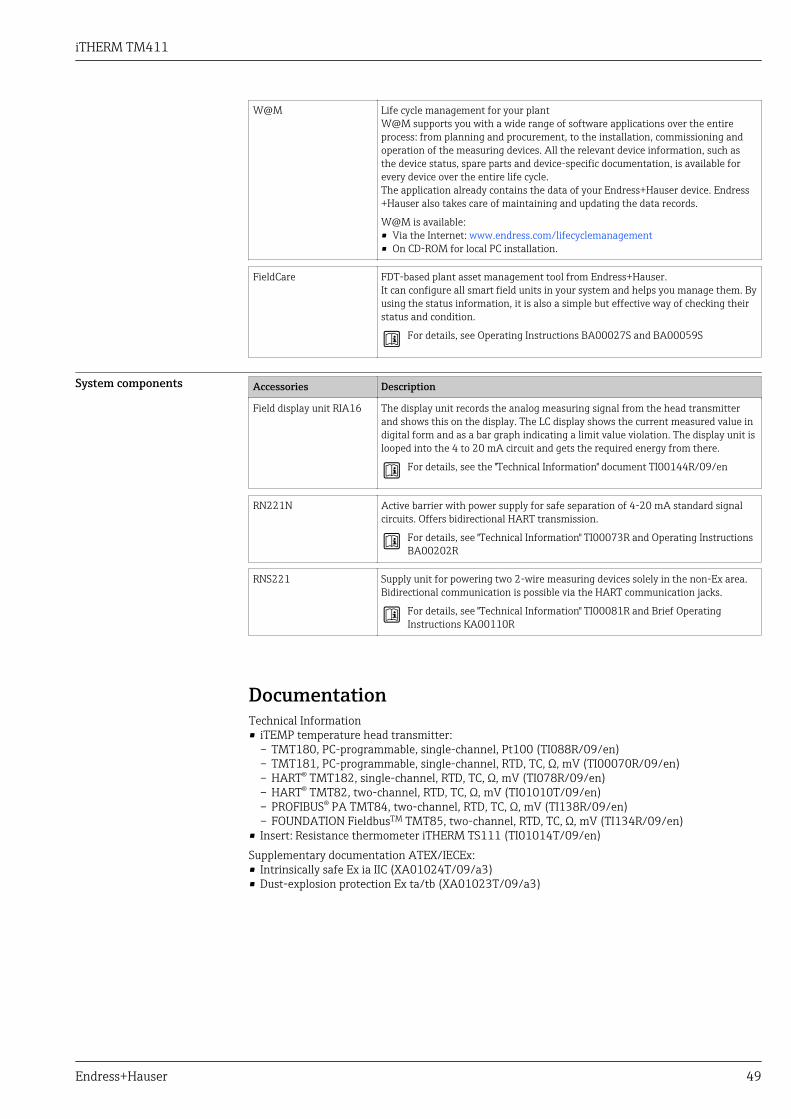
iTHERM TM411
Endress+Hauser 49
W@M Life cycle management for your plantW@M supports you with a wide range of software applications over the entireprocess: from planning and procurement, to the installation, commissioning andoperation of the measuring devices. All the relevant device information, such asthe device status, spare parts and device-specific documentation, is available forevery device over the entire life cycle.The application already contains the data of your Endress+Hauser device. Endress+Hauser also takes care of maintaining and updating the data records.
W@M is available:• Via the Internet: www.endress.com/lifecyclemanagement• On CD-ROM for local PC installation.
FieldCare FDT-based plant asset management tool from Endress+Hauser.It can configure all smart field units in your system and helps you manage them. Byusing the status information, it is also a simple but effective way of checking theirstatus and condition.
For details, see Operating Instructions BA00027S and BA00059S
System components Accessories Description
Field display unit RIA16 The display unit records the analog measuring signal from the head transmitterand shows this on the display. The LC display shows the current measured value indigital form and as a bar graph indicating a limit value violation. The display unit islooped into the 4 to 20 mA circuit and gets the required energy from there.
For details, see the "Technical Information" document TI00144R/09/en
RN221N Active barrier with power supply for safe separation of 4-20 mA standard signalcircuits. Offers bidirectional HART transmission.
For details, see "Technical Information" TI00073R and Operating InstructionsBA00202R
RNS221 Supply unit for powering two 2-wire measuring devices solely in the non-Ex area.Bidirectional communication is possible via the HART communication jacks.
For details, see "Technical Information" TI00081R and Brief OperatingInstructions KA00110R
DocumentationTechnical Information• iTEMP temperature head transmitter:
– TMT180, PC-programmable, single-channel, Pt100 (TI088R/09/en)– TMT181, PC-programmable, single-channel, RTD, TC, Ω, mV (TI00070R/09/en)– HART® TMT182, single-channel, RTD, TC, Ω, mV (TI078R/09/en)– HART® TMT82, two-channel, RTD, TC, Ω, mV (TI01010T/09/en)– PROFIBUS® PA TMT84, two-channel, RTD, TC, Ω, mV (TI138R/09/en)– FOUNDATION FieldbusTM TMT85, two-channel, RTD, TC, Ω, mV (TI134R/09/en)
• Insert: Resistance thermometer iTHERM TS111 (TI01014T/09/en)Supplementary documentation ATEX/IECEx:• Intrinsically safe Ex ia IIC (XA01024T/09/a3)• Dust-explosion protection Ex ta/tb (XA01023T/09/a3)


www.addresses.endress.com


