Item# : W52HBSBD Assembly Instructions
35
Item# : W52HBSBD Assembly Instructions Please visit our website r the most cunt stctions, assembly t 悦po mage, or quest pas. .lkedison.com Revised 12/09/2018 c。 pyright © 2018, by Walker Edis。 n Furniture C缸, LLC. All ghts 陪seed. P.1
Transcript of Item# : W52HBSBD Assembly Instructions
Item# : W52HBSBD Assembly Instructions
Please visit our website for the most current instroctions, assembly t悦report damage, or request parts. www.walkeredison.com Revised 12/09/2018
c。pyright © 2018, by Walker Edis。n Furniture C缸, LLC. All rights 陪served. P.1


Hardware List
The hardware quantities listed above are required for proper assembly.
Some extra hardware may also have been included.
A
Philips head screwdriver required for assembly
(not included)
P.4
30
pcsWooden dowel
Ø8x30mm
Copyright © 2018, by Walker Edison Furniture Co., LLC. All rights reserved.
B 25
pcsCam bolt
Ø8x35mm
C 25
pcsCam lock
Ø15x11mm
D 25
pcsSticker
Ø30mm
E 14
pcsBolt
Ø6x12mm
F
G
H
10
pcs
J
1
pcs
K
12
pcs
L
2
pcs
M
4
pcs
N
P
Q
20
pcs
R
20
pcs
S
10
pcs
T
2
pcs
U
2
pcs
V
2
pcs
Shoulder ScrewØ6x50mm
Hex KeyM 4
Shelf support pinØ8x5x16mm
Handle
M4x12mmBolt
Ø3x17mmScrew
Plastic wedge
Plastic strap
Nut
W
3
pcs
Ø4x12mmScrew
ScrewØ4x35mm
4
pcsDoor Guide
4
pcsPulley
8
pcsBolt
Ø6x12mm
X
7
pcsConnector
56x27x27mm
Ø3x45mmScrew
pcsGlue tube
1

Step 1
�叭 扩 '。
24 飞~ 〉
。
8
〉 〈
9
飞 。
〉
c。pyright © 2018, by Walker Edis。n Furniture C缸, LLC. All rights 陪served. P.5
Attach cam bolt (B) to part (24,8) with screwdriver.Insert Dowel (A) into part (9).

Insert wooden dowel (A) into part (4,5). Attach cam bolt (B) to part (4,5) with screwdriver

Attach part (8,24) to part (4,5), then insert and secure cam lock (C) to part (4,5) to lock it.

Insert wooden dowel (A) into part (6,7).

Insert wooden dowel (A) into part (11). Attach cam bolt (B) to part (1) with screwdriver.

Attach part (11) to part (1) by using screw (L) with screwdriver.

Attach cam bolt (B) to part (12,3) with screwdriver. Insert wooden dowel (A) into part (3).

Attach part (3) to part (12), then insert and secure cam lock (C) to part (3) to lock it.

Attach part (9) to part (3) using bolt (F) with hex key (G).

Attach part (5,24) to part (3,12) then insert and secure cam lock (C) in part (3,12) to lock it.
12

Attach part (4,8) to part (3,12) then insert and secure cam lock (C) in part (3,12) to lock it
12

Slide back panel (10) into grooves as per diagram.

Attach part 1 to part (4,5,9) then insert and secure cam lock (C) to part (4,5,9) to lock it.

Attach part (6) to part (3) using cam lock (C) to secure.
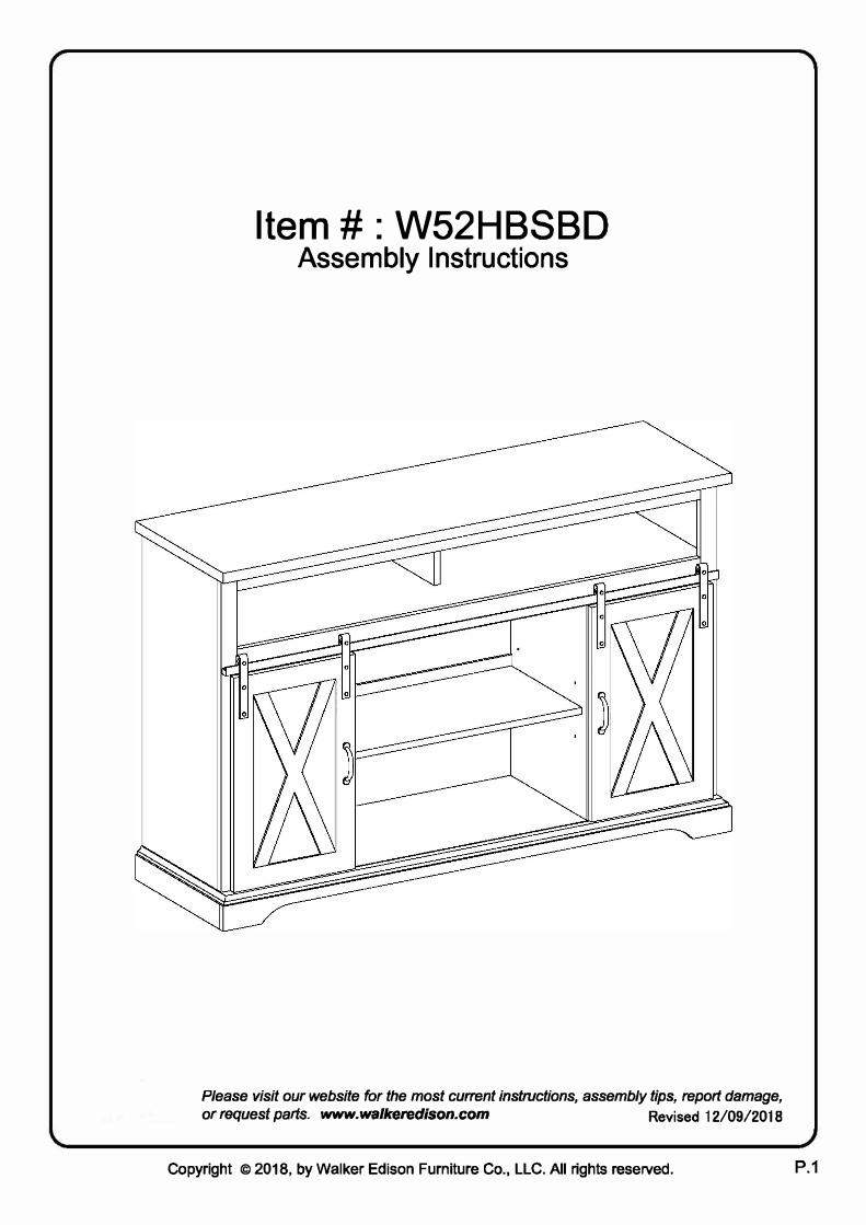
Attach part (7) to part (3), then insert and secure cam lock (C) to part (7) to lock it.

Slide back panel (16,17) into grooves as per diagram.

Attach part (13) to part (17)

Attach part (23) to part (13)

Attach part (2) to part (4,6,7,5) using Screw (F) with hex key (G).

Attach connector (R) to part (22,20,21) using bolt (E) with hex key (G).

Attach part (20) to part (21) using bolt (E) with hex key (G).

Attach part (22) to part (21) using bolt (E) with hex key (G).

Attach Base unit (20,21,22) to part (2) using connector (R) with bolt (E) and hex key (G).

Attach plastic wedge (T) using screw (S) with screwdriver.

Place sticker (D) over holes as per diagram.

Insert shelf support pin (H) into part (4,6,7,5)

Place shelf (14,15) on top of support pin.

Attach pulley (P) using bolt (Q), and plate (N) using screw (M) to part (18)(19) with screwdriver, Using Bolt(K) secure handle (J)

Place door guide (N) on door into the groove on part (2). Then hang pully (P) on
part (12). Door should fit securely and glide smoothly.
Hang pulley (P) to part (12) then press down to hold the door.

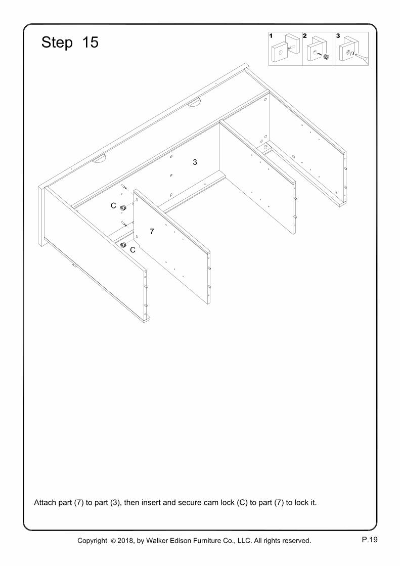
Insert Nut (W) into wall
Attach plastic strap (V) to back panel by using screw (M) with screwdriver
Insert screw (U) into plastic strap (V) by using screwdriver