ITEM #0574424 GAS PATIO HEATER - Lowes...
20
1 Garden Treasures® is a registered trademark of LF, LLC. All Rights Reserved. ATTACH YOUR RECEIPT HERE Serial Number Purchase Date Questions, problems, missing parts? Before returning to your retailer, call our customer service department at 1-800-643-0067, 8 a.m. - 8 p.m., EST, Monday - Friday. ITEM #0574424 GAS PATIO HEATER MODEL #PG167H-A Français p. 21 Español p. 42 EB14168
Transcript of ITEM #0574424 GAS PATIO HEATER - Lowes...

1
Garden Treasures® is a registered trademark of LF, LLC. All Rights Reserved. ATTACH YOUR RECEIPT HERE Serial Number Purchase Date
Questions, problems, missing parts? Before returning to your retailer, call our customer service department at 1-800-643-0067, 8 a.m. - 8 p.m., EST, Monday - Friday.
ITEM #0574424
GAS PATIO HEATERMODEL #PG167H-A
Français p. 21
Español p. 42
EB14168

2
TABLE OF CONTENTS
FOR YOUR SAFETY If you smell gas: 1. Shut off gas to the appliance. 2. Extinguish any open flame. 3. If odor continues, keep away from the
appliance and immediately call your gas supplier or fire department.
Do not store or use gasoline or other flammable vapors and liquids in the vicinity of this or any other appliance. An LP-cylinder not connected for use shall not be stored in the vicinity of this or any other appliance.
Improper installation, adjustment, alteration, service or maintenance can cause property damage, injury or death. Read the installation, operation and maintenance instructions thoroughly before installing or servicing this equipment.
For Outdoor Use Only
Product Specifications…….....................................................................................................3 Package Contents……...........................................................................................................4 Hardware Contents…….........................................................................................................5 Preparation……....……….......................................................................................................5 Safety Information……...........................................................................................................6 Assembly Instructions…….....................................................................................................8 Operating Instructions……...................................................................................................15 Care and Maintenance……..................................................................................................16 Troubleshooting…….............................................................................................................18 Warranty……........................................................................................................................18 Replacement Parts List…….................................................................................................19
DANGER WARNING
WARNING: WARNING

3
PRODUCT SPECIFICATIONS
Certification CSA Height Overall 86.6 inches Reflector Diameter 31.5 inches Rated Heat Input 45,000 BTU/HR Fuel Propane-LP Gas Supply 20-Lb LP-Gas Cylinder Manifold Pressure 11 inches W.C. Injector Size (Diameter) 2.07 mm Safety Features Thermocouple & Tilt Switch Gas Supply Pressure Max 150 PSI, Min 5 PSI

4
PACKAGE CONTENTS
PART DESCRIPTION QUANTITY PART DESCRIPTION QUANTITYA Top Dome 1 K Screw Sheath 2 B KD Dome 4 L Door Handle Bezel 2 C Burner Assembly 1 M Door Handle 1 D Pole Assembly 1 N Rear Panel 1 E Deck Ring 1 O Right Panel Assembly 1 F Table 1 P Tank Holder 1 G Table Support Bracket 2 Q Door Beam 1 H Table Rack 1 R Base Assembly 1 I Left Panel Assembly 1 S Cover 1 J Door Assembly 1
I
R
Q
P
O
H
G
F
E
D
C
B
A
M
N
L
K
J
5
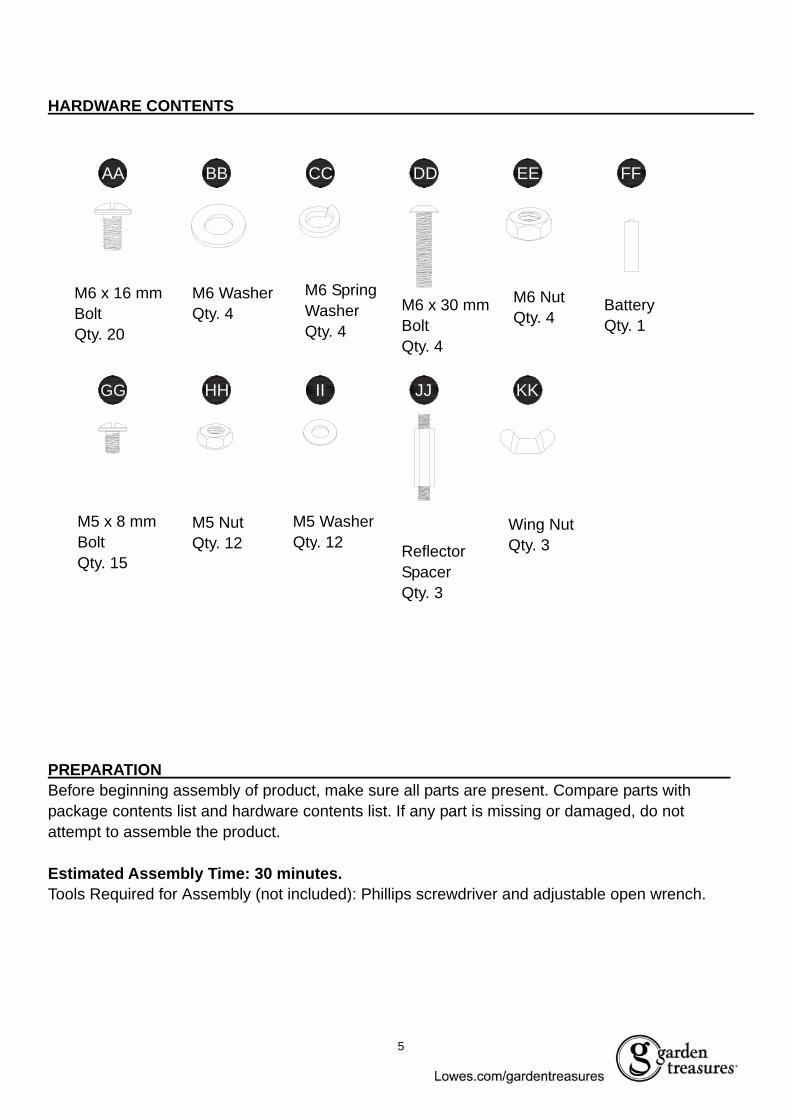
HARDWARE CONTENTS
PREPARATION Before beginning assembly of product, make sure all parts are present. Compare parts with package contents list and hardware contents list. If any part is missing or damaged, do not attempt to assemble the product. Estimated Assembly Time: 30 minutes. Tools Required for Assembly (not included): Phillips screwdriver and adjustable open wrench.
AA BB DD EE FFCC
HH IIGG JJ KK
M6 x 16 mm Bolt Qty. 20
M6 Washer Qty. 4
M6 Spring Washer Qty. 4
M6 x 30 mm Bolt Qty. 4
M6 Nut Qty. 4
M5 x 8 mm Bolt Qty. 15
M5 Nut Qty. 12
M5 Washer Qty. 12 Reflector
Spacer Qty. 3
Wing Nut Qty. 3
Battery Qty. 1

6
SAFETY INFORMATION
Please read and understand this entire manual before attempting to assemble, operate or install the product. · CALIFORNIA PROPOSITION 65 WARNING: Chemicals known to the state of California to cause
cancer, birth defects or other reproductive harm are created by combustion of propane. · The installation must conform with local codes or, in the absence of local codes, with the National
Fuel Gas Code, ANSI Z223.1 /NFPA 54, Natural Gas and Propane Installation Code, CSA B149.1, or Propane Storage and Handling Code, B149.2.
DANGER
· Young children should be carefully supervised when they are in the area of the item. · Keep the ventilation opening(s) of the cylinder enclosure free and clear from debris. Use this
appliance in a well-ventilated space only. Do not use it in a building, garage or any other enclosed area.
· Use this appliance in outdoor areas described below: (a) With walls on all sides, but at least one permanent opening at ground level and no overhead
cover. (b) Within a partial enclosure that includes overhead cover and no more than two walls. These
walls may be parallel, or at right angles to each other. (c) Within a partial enclosure that includes overhead cover and no more than two walls. The
following shall apply: (i) One wall that is equivalent to at least 25% of the total wall area is completely open. (ii) 30% or more in total of the remaining wall area is open and unrestricted.
· Store the cylinder outdoors in a well-ventilated area (not in a building, garage, or other enclosed area) out of the reach of children.
· Do not store a spare LP-gas cylinder under or near this appliance. · Never fill the cylinder beyond 80 percent full.
WARNING
· Inspect the visible portion of the hose before each use of the appliance · Perform a leak test with a soapy solution:
(a) To check gas connections. (b) After connecting a new cylinder. (c) Upon re-assembly after disassembly. Please refer to the leak test procedure indicated in this instruction manual on page 15.
· Replace the hose assembly prior to the appliance being put into operation if there is evidence of excessive abrasion or wear, or if the hose is damaged. The pressure regulator and hose assembly supplied with the appliance must be used. The replacement hose assembly/regulator shall be that specified by the manufacturer.
· Place the propane hose with regulator assembly out of pathways where people may trip over it or in areas where the hose will not be subjected to accidental damage.

7
SAFETY INFORMATION
· The cylinder used must include a collar to protect the cylinder valve. · Installation and repair should be done by qualified service person; the heater should be inspected
before use and at least annually by a qualified service person. · Do not obstruct the flow of combustion and ventilation air. · The LP-gas supply cylinder to be used must be:
(a) Constructed and marked in accordance with the Specifications for LP-gas cylinders of the U.S. Department of Transportation of Dangerous Goods and Commission, CAN/CSA-B339, as applicable;
(b) Provided with a listed overfilling prevention device; and (c) Provided with a cylinder connection device compatible with the connection for the appliance.
· Disconnect the cylinder when the appliance is not in use. · Storage of an appliance indoors is permissible only if the cylinder is disconnected and removed
from the appliance. · Materials or items when stored under the heater will be subjected to intense heat and could be
seriously damaged. · Clothing or other flammable materials should not be hung on the heater, or placed on, under or
near the heater. · Children and adults should be alerted to the hazards of high surface temperatures and should
stay away from the item to avoid burns or clothing ignition. · Place the dust cap tightly on the cylinder valve outlet whenever the cylinder is not in use. Install
only the type of dust cap on the cylinder valve that is provided with the cylinder valve. Other types of caps or plugs may result in a propane leak.
CAUTION · Minimum clearance to the combustible materials is 44 inches. · If you don’t feel the heater is on a stable surface, use a ground screw to fix the base of the heater
on the surface where the heater is installed. Fix the base on an incline no wider than 15 degrees. · This heater is equipped with a battery-operated ignition device; please refer to the Assembly
Instructions on page 8. · Any guard or other protective device removed for servicing the heater must be replaced prior to
operating the heater. · More frequent cleaning may be required as necessary. It is imperative that the control
compartment, burners and circulating air passageways of the heater to kept clean. · Keep the appliance area clear and free from combustible materials, gasoline and other flammable
vapors and liquids. · Inspect the visible portion of the hose before each use of the appliance. When portions of the
hose are located within the confines of the heater post, instructions to inspect the entire hose assembly at least annually. If disassembly is required, the instructions shall also include the proper procedure for leak checking the connections upon re-assembly.
· More frequent cleaning may be required as necessary. It is imperative the control compartment, burners and circulating air passageways of the heater are kept clean.
· Keep this manual for future reference and to educate new users of this product.
8
ASSEMBLY INSTRUCTIONS
Hardware Used
Hardware Used
Hardware Used
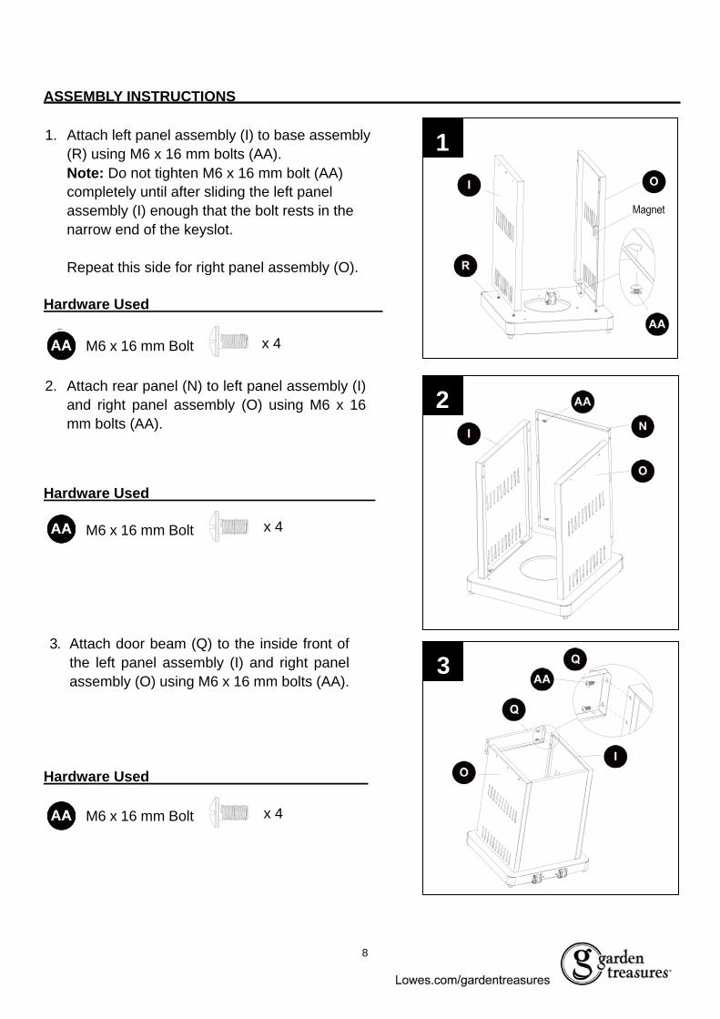
1. Attach left panel assembly (I) to base assembly (R) using M6 x 16 mm bolts (AA). Note: Do not tighten M6 x 16 mm bolt (AA) completely until after sliding the left panel assembly (I) enough that the bolt rests in the narrow end of the keyslot. Repeat this side for right panel assembly (O).
2. Attach rear panel (N) to left panel assembly (I) and right panel assembly (O) using M6 x 16 mm bolts (AA).
3. Attach door beam (Q) to the inside front of the left panel assembly (I) and right panel assembly (O) using M6 x 16 mm bolts (AA).
1
AA M6X10 Bolt X 4
AA M6X10 Bolt X 4
AA M6X10 Bolt X 4
3
M6 x 16 mm Bolt
M6 x 16 mm Bolt
AA
Q
I
O
Q
M6 x 16 mm Bolt
x 4
x 4
x 4
2 AA
N I
O
O I
AA
R

9
ASSEMBLY INSTRUCTIONS Hardware Used
Hardware Used
4. Attach door handle bezel (L) on both sides of the door handle (M). Insert screw sheaths (K) into the holes on the backside of door assembly (J). Then, attach door handle assembly to door assembly (J) using M6 x 16 mm bolts (AA) through the screw sheaths (K) and into the preassembled door handle bezels (L) on door handle (M).
5. Insert the preassembled sheath on the bottom of door assembly (J) into the base assembly (R). Then, push down the preassembled spring sheath at the top of door assembly (J) until it locks into door beam (Q).
AA M6X10 Bolt X 2
66. Place table rack (H) into the cabinet and
table support bracket (G) against right panel assembly (O). With holes aligned, secure using M6 x 16 mm bolts (AA).
Repeat for left panel assembly (I).
AA M6X10 Bolt X 6
M6 x 16 mm Bolt
M6 x 16 mm Bolt
x 2
x 6
AA
GH
O I
J
Q
R
5
4M L
K
J
AA
L M

10
ASSEMBLY INSTRUCTIONS
Hardware Used
7. Open door assembly (J). Then, from inside, secure pole assembly (D) to table rack (H) using M6 x 30 mm bolts (DD), M6 washers (BB), M6 spring washers (CC) and M6 nuts (EE).
BB
CC
DD
EE
X4M6 Washer 18X6.5X1.5
M6 Nut X4
M6 Stretchy Washer X4
M6 X 30mm Bolt X4
7
8. Remove the bolts and washers preassembled underneath the table (F). Insert table (F) over the pole assembly (D), carefully resting it on table support rack (G). Secure from underneath with previously removed bolts and washers.
M6 Washer
M6 Spring Washer
M6 x 30 mm
M6 nuts
x 4
x 4
x 4
x 4
F
G
D
F
G
8
H
D
E E
B B
C C
D D
J

11
ASSEMBLY INSTRUCTIONS
9. Insert the deck ring (E) over the pole assembly (D) so it rests on top of table (F). 9
10. From inside the cabinet, secure the left end of the tank holder (P) into the holder preassembled on left panel assembly (O). Then lock the other end of the tank holder (P) into the holder on right panel assembly (I). Note: The tank holder (P) is highly recommended to be installed as it can prevent a gas tank from shaking.
10
E
F
D
P
O
I

12
ASSEMBLY INSTRUCTIONS
Hardware Used
12. Thread the regulator assembly preassembled to burner assembly (C) through the pole assembly (D). Once the burner assembly (C) rests on pole assembly (D), secure with M5 x 8 mm bolts (GG).
11. Insert reflector spacers (JJ) into the top of burner assembly (C).
12
X 12M5 X 8 mm Bolt
X 125 mm Washer
M5 Nut X 12HH
II
GG M5 x 8 mm Bolt x 3
11 JJ
C
11
C
C15
D
D
FF
C

13
ASSEMBLY INSTRUCTIONS
Hardware Used
Hardware Used
Hardware Used
Attach KD domes (B) using M5 x 8 mm bolts (GG), M5 nuts (HH) and M5 washers (II). Then, complete dome assembly by attaching top dome (A) to KD domes (B) with M5 x 8 mm bolts (GG), M5 nuts (HH) and M5 washers (II).
14. Attach dome assembly to burner assembly (C) by securing wing nuts (KK) to reflector spacers (JJ).
A
B
II
HH
GG
HH
II
GG
13
A
B
KK
C
JJ
14
Wing NutKK x 3Wing nut x 3
13.
X 12M5 X 8 mm Bolt
X 125 mm Washer
M5 Nut X 12HH
II
GG M5 x 8 mm Bolt x 12
x 12
x 12
M5 Nut
M5 Washer
14
ASSEMBLY INSTRUCTIONS
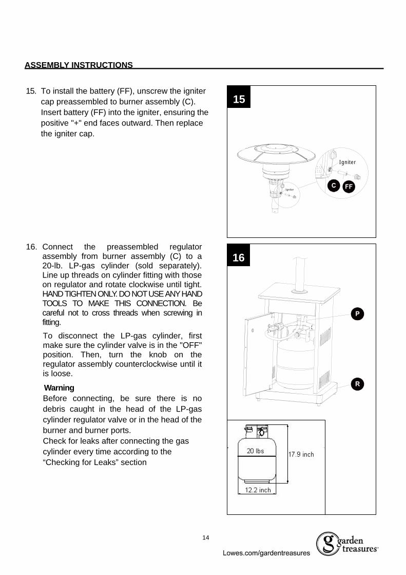
16. Connect the preassembled regulator assembly from burner assembly (C) to a 20-lb. LP-gas cylinder (sold separately). Line up threads on cylinder fitting with those on regulator and rotate clockwise until tight. HAND TIGHTEN ONLY. DO NOT USE ANY HAND TOOLS TO MAKE THIS CONNECTION. Be careful not to cross threads when screwing in fitting. To disconnect the LP-gas cylinder, first make sure the cylinder valve is in the "OFF" position. Then, turn the knob on the regulator assembly counterclockwise until it is loose.
Warning Before connecting, be sure there is no debris caught in the head of the LP-gas cylinder regulator valve or in the head of the burner and burner ports. Check for leaks after connecting the gas cylinder every time according to the “Checking for Leaks” section
15. To install the battery (FF), unscrew the igniter cap preassembled to burner assembly (C). Insert battery (FF) into the igniter, ensuring the positive "+" end faces outward. Then replace the igniter cap.
15
16
Igniter
Igniter CLL
P
R

15
OPERATING INSTRUCTIONS
Fig.15 Lighting Instructions
1. Ensure the LP-gas cylinder valve and the item's control knob are in the "OFF" position. If not, turn off and wait 5 minutes for any gas to clear. 2. Turn the LP-gas cylinder valve "ON" and push the item's control knob in and rotate it to "PUSH." Then, push the item's igniter button and control knob until the burner lights. Note: If the burner fails to remain lit or is extinguished, repeat step 2 after waiting the necessary 5 minutes when completing the shutoff process. 3. Once the burner has lit, continue to hold the control
knob in for 30 seconds, and then release. 4. Turn the control knob from "LOW" to "HIGH" until the desired heat setting is reached. 5. Visually check the burner flame against the
illustrations below: 1) Flame should be blue with slight yellow tips. 2) You should see a smaller flame in LOW position
than seen on HIGH. Perform flame check prior to each use. If only low flame is seen, refer to “Burner flame is low” in the “TROUBLESHOOTING” on page 18.
1
For complete shutdown: 1. Turn the item's control knob to "PUSH", then push and turn to "OFF" for a complete shutoff. 2. Turn the LP-gas cylinder valve to the "OFF" position, then remove the tank, if desired.
Checking for Leaks
a. Make leakage solution by mixing 1-part liquid dish soap and 3-parts water. b. Spoon or brush several drops (or use squirt bottle) of the solution onto the gas hose/regulator and
regulator/cylinder and hose connections. c. Turn on gas cylinder valve. Inspect the connections and look for bubbles.
1. If no bubbles appear, the connection is safe. 2. If bubbles appear, there is leakage. Loosen and re-tighten this connection. If it still leaks, please call
customer service. Note: Whenever gas connections are loosened, removed or re-assembled, you must perform a complete leak test.

16
OPERATING INSTRUCTIONS
CARE AND MAINTENANCE · Abrasive cleaners will damage this product. · Never use oven cleaner to clean any part of heater · Do not clean any heater part in a self-cleaning oven. The extreme heat will damage the finish. · More frequent cleaning may be required as necessary. It is imperative that control compartment,
burners and circulating air passageways of the heater be kept clean. · Spiders and insects can create a dangerous condition that may damage heater or make it unsafe.
Keep burner area clean of all spiders, webs or insects. Clean burner holes by using a heavy-duty pipe cleaner. Compressed air may help clear away smaller particles.
· Inspect heater before each use.
· Have heater inspected annually and repairs should be made by a qualified service person. · Check heater immediately if any of the following conditions exist:
a. The smell of gas in conjunction with extreme yellow tipping of burner flames b. Heater does not reach proper temperature. c. Heater’s glow is excessively uneven. d. Burner makes popping noises during use. Note: A slight pop is normal when burner is extinguished.
· Carbon deposits may create a fire hazard. Keep dome and emitter clean at all times. · Do not clean heater with combustible or corrosive cleaners. Use warm, soapy water. · Do not paint engine, engine access panel or dome. · This heater should be thoroughly cleaned on a regular basis. · After a period of storage and/or non use, check for leaks, burner obstructions and inspect for any
abrasion, wear, cuts to the hose. · Periodically check the hose located within the confines of the cylinder housing for damage.
In any case of failure of normal ignition, please use the ignition bar with a match to reach the burner for ignition through the hole on the bottom of burner diffuser. Insert the match from the back side of the burner assembly where is opposite to the control panel.
WARNING
If at any time you are unable to light burner and smell gas, wait 5 minutes to allow gas to dissipate before attempting to light heater. WARNING DO NOT touch or move heater for at least 45 minutes after use. Allow emitter and dome to cool before touching. WARNING: Avoid inhaling fumes emitted from the heater’s first use. Smoke and odor from the burning of oils used in manufacturing will appear. Both smoke and odor will dissipate after approximately 30 minutes. The heater should NOT produce thick black smoke.
2

17
CARE AND MAINTENANCE Cleaning · Wipe surfaces clean with mild dish detergent or baking soda. · For stubborn surfaces use a citrus-based degreaser and a nylon scrubbing brush. · Rinse clean with water.
Note: While cleaning the unit, be sure to keep the area around the burner dry at all times. Do not submerge the control valve assembly. If the gas control is submerged in water, do NOT use it. It must be replaced.
TIP: Use high-quality automobile wax to help maintain the appearance of the heater. Apply to exterior surfaces from the pole down. Do not apply to emitter screen or domes
Maintenance · Keep exterior surfaces clean. · Air flow must be unobstructed. Keep controls, burner and circulating air passageways clean.
Signs of possible blockage include: Gas odor with extreme yellow tipping of flame. Heater does NOT reach the desired temperature. Heater glow is excessively uneven. Heater makes popping noises.
Note: In a salt-air environment (such as near an ocean) corrosion occurs more quickly than normal. Frequently check for corroded areas and repair them promptly. Storage Between uses or during periods of extended inactivity:
· Turn control knob to "OFF". · Disconnect LP cylinder and move to a secure, well-location outdoors. · Store heater upright in an area sheltered from direct contact with inclement weather (such as rain,
sleet, hail, snow, dust and debris). Note: Never leave LP gas tank exposed to direct sunlight or excessive heat.
· If desired, use cover (s) to protect the heater and help prevent buildup in air passages. CAUTION: Wait until heater is cool before covering.

18
TROUBLESHOOTING PROBLEM POSSIBLE CAUSE CORRECTIVE ACTION Burner doesn’t light. 1. Gas pressure is low.
2. The orifice is blocked. 3. Control knob is not in “ON”
position.
1. Turn the gas cylinder valve “OFF” and replace the cylinder.
2. Clear blockage. 3. Turn control knob to “ON”
Burner flame is low. 1. Gas pressure is low. 2. The control knob is not
positioned at “High”. 3. The burner jet is partially
blocked. 4. Outdoor temperature is less
than 40°F and/or tank is less than 1/4 full.
5. Supply hose is bent or kinked.
1. Turn the gas cylinder valve “OFF” and replace the cylinder.
2. Position the control knob at “High” 3. Clear blockage. 4. Use a full gas cylinder. 5. Straighten the hose.
Carbon buildup. Seasonal accumulation. Wipe off before lighting.
Thick black smoke. Blockage in burner. Remove blockage and clean burner inside and outside.
WARRANTY
The appliance has been manufactured under the highest standards of quality and workmanship. We warrant to the original consumer/purchaser that all aspects of this product will be free of defects in material and workmanship for one (1) year from the date of purchase. Replacements for any defective part will be supplied free of charge for installation by the consumer. Defects or damage caused by the use of other than genuine parts are not covered by this warranty. This warranty shall be effective from the date of purchase as shown in the purchaser’s receipt. This warranty is valid for the original consumer purchaser only and excludes industrial, commercial or business use of the product, product damage due to shipment or failure which results from alteration, product abuse or product misuse, where performed by a container, service company or consumer. We will not be responsible for labor charges and/or damage incurred in installation, repair or replacement, nor for incidental or consequential damage. This warranty gives you specific legal rights, and you may also have the other rights that vary from state to state.

19
REPLACEMENT PARTS LIST For replacement parts, call our customer service department at 1-800-643-0067, 8 a.m. - 8 p.m., EST, Monday - Friday

20
REPLACEMENT PARTS LIST
PART DESCRIPTION PART # PART DESCRIPTION PART # 1 Top Dome 5007755 17 Door Handle Bezel 24064882 KD Dome 5007756 18 Door Handle 50152403 Burner Chamber Assembly 5203139 19 Rear Panel 5203093
4 Burner Assembly 0574423 -4 20 Right Panel 5203092
5 Knob 2100462 21 Tank Holder 24064896 Valve Shroud Cover 5203146 22 Door Beam 52030947 Igniter 2406521 23 Magnet 23066228 Pole Assembly 5203088 24 Base 52030979 Deck Ring 5201949 25 Base Support 520309810 Granite Table 2406487 26 Wheel 240474711 Table Support Bracket 5203089 27 Wheel Support 520309912 Table Rack 5203090 28 Tip Cushion 240407613 Left Panel Assembly 5203091 29 Weight Plate 240653314 Spring Sheath 2306703 30 Cover 3106103
15 Door 0574424 -15 31 Hardware Pack 5203215
16 Screw Sheath 2100481
Printed in China Garden Treasures® is a registered trademark
of LF, LLC. All Rights Reserved.