
ITEC420 Software Engineering Lecture 3: Recap OO…box/itec420/lecture03.pdf · ITEC420: Software...
54
ITEC420: Software Engineering Lecture 3: Recap OO/UML Requirement Workflow Box Leangsuksun SWECO Endowed Professor, Computer Science Louisiana Tech University [email protected] CTO, PB Tech International Inc. naibox@gmail.com
Transcript of ITEC420 Software Engineering Lecture 3: Recap OO…box/itec420/lecture03.pdf · ITEC420: Software...

ITEC420: Software Engineering Lecture 3: Recap OO/UML Requirement Workflow Box Leangsuksun SWECO Endowed Professor, Computer Science Louisiana Tech University [email protected]
CTO, PB Tech International Inc. [email protected]

The Unified Modeling Language

Communication Using the Unified Modeling Language
Data Modeling
Web Modeling
One language – One tool – One team
Application Modeling
Business Modeling
Requirements Modeling

Host or Target Application
The Developer’s View
The Model is The Application
Use Case Diagram
Sequence Diagram
Class Diagram
Structure Diagram
Behavior Diagram
Component Diagram
Deployment Diagram
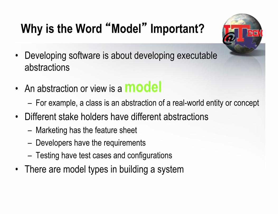
Why is the Word “Model” Important?
• Developing software is about developing executable abstractions
• An abstraction or view is a model – For example, a class is an abstraction of a real-world entity or concept
• Different stake holders have different abstractions – Marketing has the feature sheet – Developers have the requirements – Testing have test cases and configurations
• There are model types in building a system

UML Models
• Models capture – the structural, or static, features of systems – the behavioral, or dynamic, features of systems.
• Models have several independent dimensions – Each emphasize particular qualities of a model – Each dimension has a diagram type

UML Diagrams
• Use case diagrams depict the functionality of a system. • Class and object diagrams for the static structure • Sequence (collaboration) diagrams for behavior in a scenario • State diagrams for execution • Activity diagrams for process descriptions • Component diagrams for dependencies between components • Deployment diagrams for configuration and environment
RECAP last lecture
12/12/13 8

9
Basic Principles of Object Orientation
Object Orientation • Abstraction • Encapsulation • Modularity • Hierarchy

10
Classes of Objects
• How many class can you see?
11
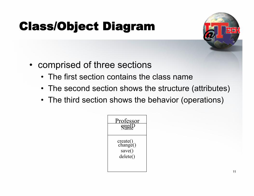
Class/Object Diagram
• comprised of three sections • The first section contains the class name • The second section shows the structure (attributes) • The third section shows the behavior (operations)
Professor Name
save() change() delete()
empID
create()

Class/Object Diagram
12/12/13 12
Professor Name
save() change() delete()
empID
create()
Professor Name
empID
Professor
save() change() delete()
create()
Professor
Professor

13
Interface
<<interface>>
Shape
Scale Move Rotate
Draw
Tube
Pyramid
Cube
Canonical
(Class/Stereotype)
presentation
Tube
Pyramid
Cube
Elided/Iconic
Representation
(“lollipop”)
14
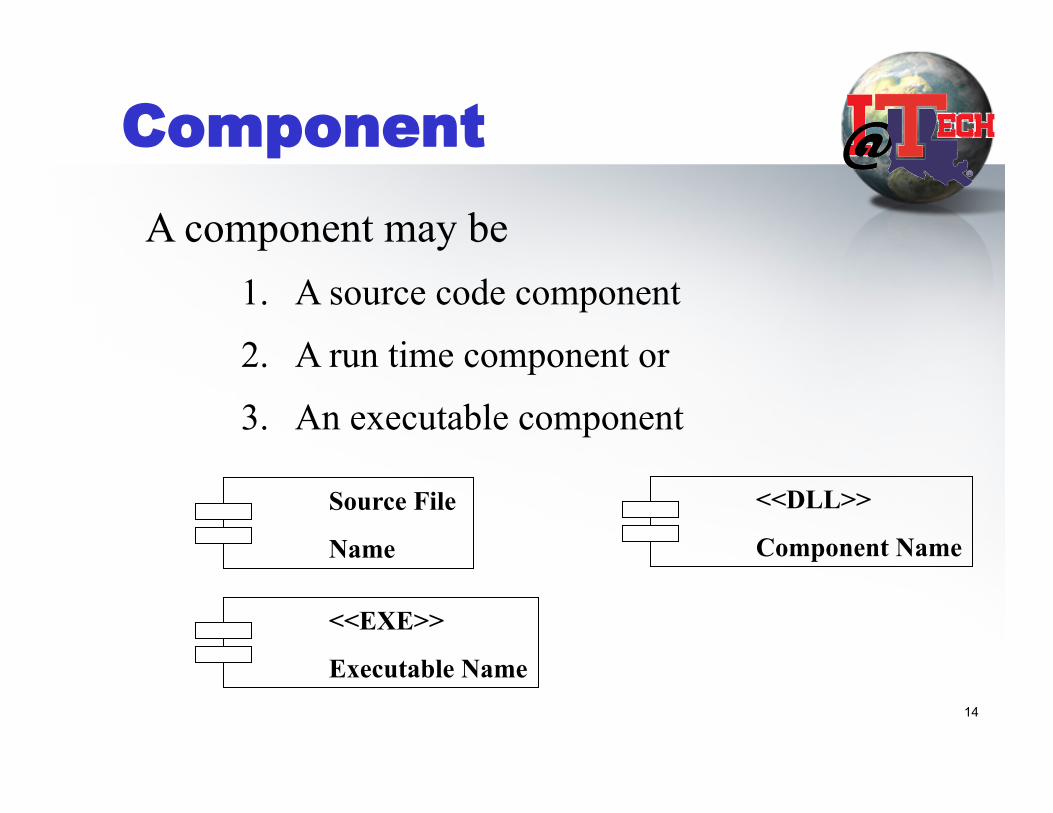
Component
Source File
Name
<<EXE>>
Executable Name
<<DLL>>
Component Name
A component may be 1. A source code component
2. A run time component or
3. An executable component

15
Relationships
• Association • Aggregation • Composition
• Dependency • Generalization • Realization
16
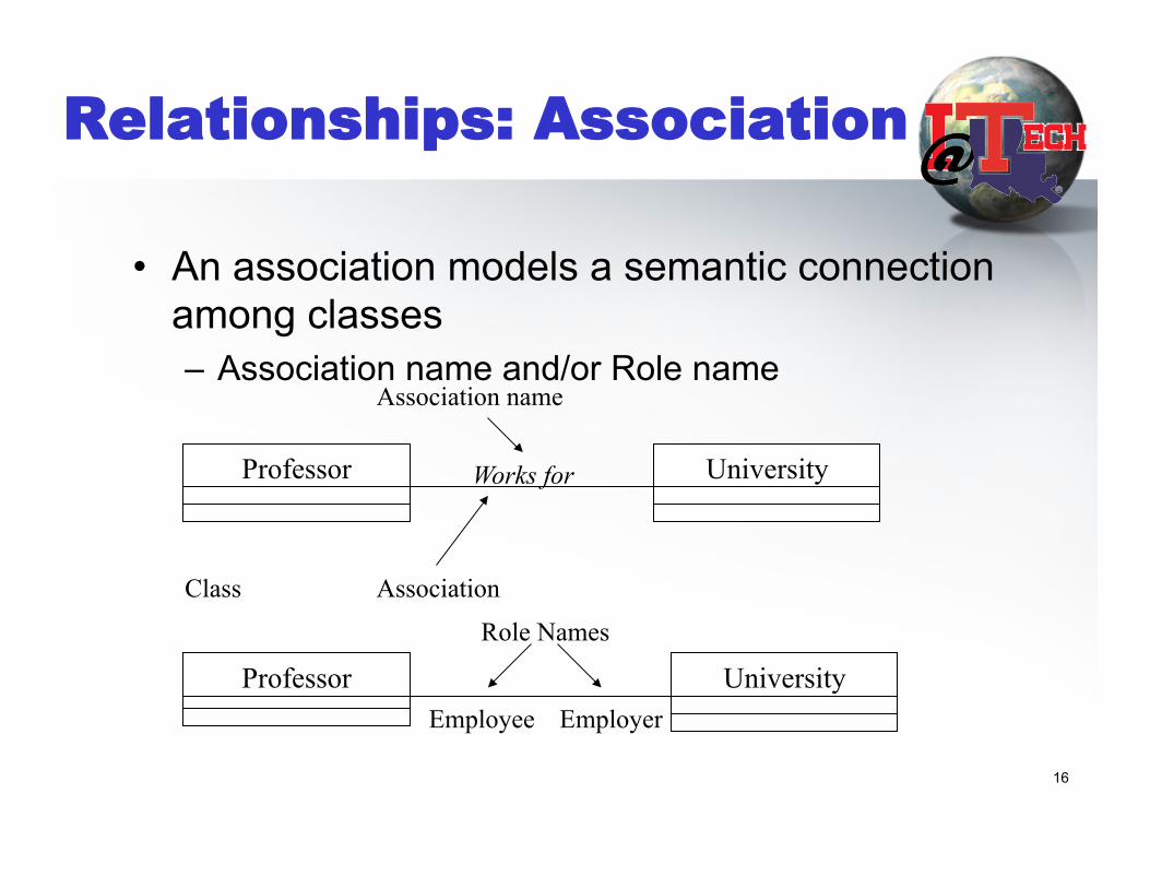
Relationships: Association
• An association models a semantic connection among classes – Association name and/or Role name
Professor University
Professor University
Class
Association name
Works for
Association
Employee Employer
Role Names

17
Relationship: Aggregation
• A special form of association that models a whole-part relationship between an aggregate (the whole) and its parts
Student Schedule
Whole Part
Aggregation

18
Relationship: Composition
• A form of aggregation with strong ownership and coincident lifetimes • The parts cannot survive the whole/aggregate
Human Heart (organ)
Aggregation
Whole Part

19
Association: Multiplicity
• Unspecified • Exactly one • Zero or more (many, unlimited)
• One or more • Zero or one • Specified range • Multiple, disjoint ranges
1
0..*
*
1..*
0..1
2..4
2,4..6

20
Example:
GroundVehicle weight licenseNumber register()
Person
Car size
getTax()
Truck tonnage
Trailer
0..* 1 owner
Generalization
Superclass
(parent)
Subclasses

View of Software Engineering
User Needs/Inputs – Specification or Requirement
Technical: Design/Analysis Implementation
Project/Product Management:
Manufacturing/ Quality Control

Product Life cycle (RUP)
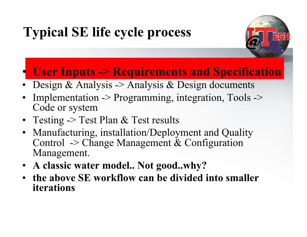
Typical SE life cycle process
• User Inputs -> Requirements and Specification • Design & Analysis -> Analysis & Design documents • Implementation -> Programming, integration, Tools ->
Code or system • Testing -> Test Plan & Test results • Manufacturing, installation/Deployment and Quality
Control -> Change Management & Configuration Management.
• A classic water model.. Not good..why? • the above SE workflow can be divided into smaller
iterations
Requirements and Specifications
• User Inputs/expectations are translated into agreement documents among users/customers and various stakeholders in SE lifecycle
• Can be legal documents between client and supplier
• How do we know whether the software product will meet the expectation?

Requirements and Specifications
• Functional Requirements – Tangible Needs – E.g. your order processing system, online store with shopping cart.
• Non-Functional Requirements – Performance (how well your system can perform, # transaction) – Reliability (how long your system can run w/o failure or what is
uptime?)
• How do we know whether the software product will meet the expectation?

Requirements workflow

Outline
• Introduction. • Requirement Engineering • Capture requirements. • Artifacts. • Workers. • Activities. • Next step.

What are requirements? • “What customers or users expect from the
system” • Two types
– Functional Requirements • Features (more tangible)
– Non-functional requirements • Reliability and performance (equally if not more)

Why important?
• Standish (1995) reports from pfleeger’s book, – Incomplete requirement (13.1%) – Lack of user involvement (12.4%) – Lack of resources (10.6%) – Unrealistic expectations (9.9%) – Lack of executive support (9.3%) – Changing req and spec (8.7%) – Lack of planning (8.1%)

Capture requirement
• Reach agreement on system context – provided by customers – Vision statement (e.g from marketing/product team) – Survey or research
• Come up with Abstractions of a given problem
domain • Arrive at actions representing/involving the
abstractions (USE-CASES)

Introduction
• The fundamental principles. • Difficulties.
- communication. - articulation. - clarity.

Requirements Engineering
• Establishing what the customer requires from a software system
what is it

Requirements engineering
• The process of establishing the services that the customer requires from a system and the constraints under which it operates and is developed
• Requirements may be functional or non-functional – Functional requirements describe system services or
functions – Non-functional requirements is a constraint on the
system or on the development process

What is a requirement?
• It may range from a high-level abstract statement of a service or of a system constraint to a detailed functional specification
• This is inevitable as requirements may serve a dual function – May be the basis for a bid for a contract - therefore
must be open to interpretation – May be the basis for the contract itself - therefore
must be defined in detail – Both these statements may be called requirements

Requirements definition/specification
• Requirements definition – A statement in natural language plus diagrams of the
services the system provides and its operational constraints. Written for customers
• Requirements specification – A structured document setting out detailed descriptions
of the system services. Written as a contract between client and contractor
• Software specification – A detailed software description which can serve as a
basis for a design or implementation. Written for developers

Requirements readers
Client managersSystem end-usersClient engineersContractor managersSystem architects
System end-usersClient engineersSystem architectsSoftware developers
Client engineers (perhaps)System architectsSoftware developers
Requirementsdefinition
Requirementsspecification
Softwarespecification

The Unified Modeling Language

• Requirements -> graphical notations • -> UML usecase
12/12/13 38

USE CASE
• A series of actions that an actor performs in conjunction with a system to achieve a particular goal
• It only describes what but not the how a system needs to do.
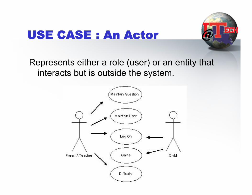
USE CASE : An Actor
Represents either a role (user) or an entity that interacts but is outside the system.

More actor (excerpted from wiki)
• an actor is something or someone who supplies a stimulus to the system. An actor cannot be controlled by the system and is defined as being outside the system.
• An actor is often thought of as a role, rather than an actual person or system. A single person in the real world can be represented by several actors if they have several different roles and goals in regard to a system.

Use case process & notation
• Identify actors • Brain-storm actions that will lead to features/
promises to customers • Refine use-cases and add exception cases • eg. A doctor clinic

USE CASE types
• Main flow of events • Exceptional flow of events

Class Example
• What are usecases for an e-mail system?

Sample of e-mail system use cases/requirements
CC system
validate CCCCInterface* *


Capture requirements
• Reach agreement on system context - Domain (e.g. technical) model
• Abstraction of a given problem domain - Business Model
- Use case diagrams and business actor • List candidate requirements • Identify and negotiate functional requirements –
USECASES • Specify non-functional requirements
– Expressed in a supplemental document and/or as constraints in the UML diagrams

Artifacts.
• Actor • Use case • User-interface prototype • Use case model • Architecture description • Supplementary requirements

Artifacts and workers

Workers
• System Analyst. • Use case specifier • User-interface designer • architect

Activities
• Build domain model • Build business model • Find actors and use cases • Prototype the user interface • Prioritize the use cases • Detail a use case • Structure the use case model
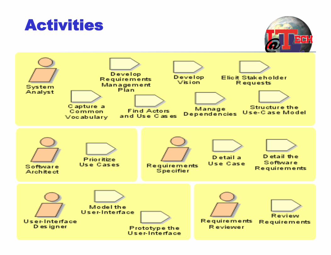
Activities
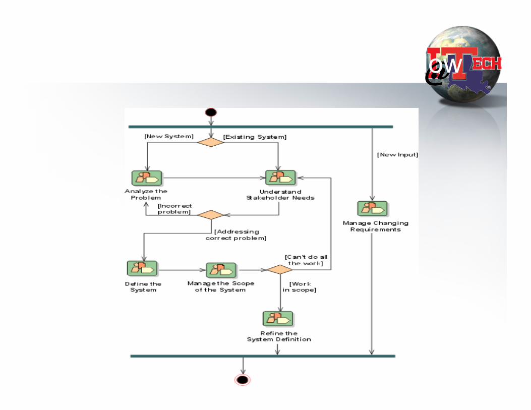
Requirement workflow

Class Exercise
1. follows the req workflow guideline and works for ATM systems
– Brainstorm Actors – Finding use cases
– For online students, please submit your requirement documents based on this template for ATM (online Banking)
– Requirement document template: http://www.latech.edu/~box/ase/srs_template.doc


![(1) YAMAHA H 30 El oo o 00 0 0 00 0 2.ñ 1 oa o oo oo oo o ... · 00 -2 12B F] 30 o 000 00 00 0 o oo o o 0 00 00 o oo oo oo 00 0 (2) 0 00 00 o oo o oo oo oo o 0 00 00 00 oo o oo o](https://static.fdocuments.in/doc/165x107/5ffe50972fd0a110ae2411d9/1-yamaha-h-30-el-oo-o-00-0-0-00-0-2-1-oa-o-oo-oo-oo-o-00-2-12b-f-30-o.jpg)