iT500 Internet Thermostat...When fitting batteries, do not mix old and new batteries together. Do...
28
iT500 Internet Thermostat INSTALLER MANUAL
Transcript of iT500 Internet Thermostat...When fitting batteries, do not mix old and new batteries together. Do...

iT500 Internet Thermostat
I N S T A L L E R M A N U A L
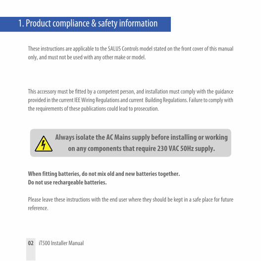
1. Product compliance & safety information
These instructions are applicable to the SALUS Controls model stated on the front cover of this manual only, and must not be used with any other make or model.
This accessory must be fitted by a competent person, and installation must comply with the guidance provided in the current IEE Wiring Regulations and current Building Regulations. Failure to comply with the requirements of these publications could lead to prosecution.
When fitting batteries, do not mix old and new batteries together. Do not use rechargeable batteries. Please leave these instructions with the end user where they should be kept in a safe place for future reference.
02 iT500 Installer Manual
Always isolate the AC Mains supply before installing or working on any components that require 230 VAC 50Hz supply.

Wire up the receiver using one of the schematics on pages 4 and 5
Clip the front of the unit back on by aligning the fittings and pushing into place.
Securely screw the front of the receiver in place.
4 5 6
Loosen the screws at the bottom of the receiver unit.
Unclip the front of the unit. Fit the back of the receiver unit to the wall using the fittings supplied.
1 2 3
2. Installation of the iT500RX Receiver
iT500 Installer Manual 03

230V0V
BOILER
Volt Free - Combination Boiler
BOILER
230V230V
2 x CH Zones - Volt Free Combination Boiler
BOILER
OV - 230v
BOILER
OV 230
230V
230V
230V
0V System Boiler 1 x CH Zone and 1 x HW Zone
BOILER
OV
BOILER
OV
230V0V
BOILER
Volt Free - Combination Boiler
BOILER
230V230V
2 x CH Zones - Volt Free Combination Boiler
BOILER
OV - 230v
BOILER
OV 230
230V
230V
230V
0V System Boiler 1 x CH Zone and 1 x HW Zone
BOILER
OV
BOILER
OV
230V230V
BOILER
230V Switching - Combination Boiler
BOILER
230V230V
230V Combination Boiler 2 x CH Zones - Potential Volt Free Switching
BOILER
OV - 230v
BOILER
OV 230
230V
230V
230V
0V System Boiler 1 x CH Zone and 1 x HW Zone
BOILER
OV
BOILER
OV
04 iT500 Installer Manual
Two central heating zones.iT300 Sensor required for this configuration.
A
C +
One central heating zone only.A
One central heating zone only.B
B
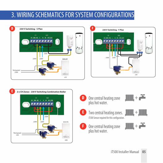
3. WIRING SCHEMATICS FOR SYSTEM CONFIGURATIONS
C
230V
230V
230V
230 V Switching
BOILER
230
Permanent230
BOILER
230
Potential Free Switching
BOILER
230V0-230V
BOILER
230V
230V
230V
2 x CH Zones - 230 V Switching Combination Boiler
BOILER
230
Permanent230
BOILER
230
230V230V
Potential Free Switching
BOILER
230
BOILER
230
230V
230V
230V
Potential Free Switching - S Plan
BOILER
OV
BOILER
OV
230V
230V
230V
230 V Switching - S Plan
BOILER
230
BOILER
230
Permanent230V
2C
D
E
3. WIRING SCHEMATICS FOR SYSTEM CONFIGURATIONS
One central heating zone plus hot water.
D +
F One central heating zone plus hot water.
+
+Two central heating zones.iT300 Sensor required for this configuration.
E
iT500 Installer Manual 05
230V230V
230V
230 V Switching - Y Plan
BOILER
230
BOILER
230
Potential Free Switching
BOILER
230V0-230V
BOILER
230V
230V
230V
230 V Switching
BOILER
230
Permanent230
BOILER
230
230V230V
Potential Free Switching
BOILER
230
BOILER
230
230V
230V
230V
Potential Free Switching
BOILER
OV
BOILER
OV
2 1 C
F
230V230V
230V
230 V Switching - Y Plan
BOILER
230
BOILER
230
Potential Free Switching
BOILER
230V0-230V
BOILER
230V
230V
230V
230 V Switching
BOILER
230
Permanent230
BOILER
230
230V230V
Potential Free Switching
BOILER
230
BOILER
230
230V
230V
230V
Potential Free Switching
BOILER
OV
BOILER
OV
2 1 C

1 2 3
4. Installation of wall bracket docking (optional)
5. Desk mount option iT500
Attach the wall mounting bracket to a suitable wall using the fittings supplied
and the built in level.
For the desk mounted option, simply clip the clear stand supplied separately into
the back of the unit.
After first ensuring that the bracket is secure, clip the iT500 into place by
aligning the recess on the back of the unit to the bracket and clipping into place.
Once clipped into place, ensure the unit is securely seated on the bracket.
06 iT500 Installer Manual
For best results mount the iT500 1.5m from ground level.i

6. Connecting the Gateway to your existing router
Flashing red light on setup.
Constant green light when the iT500 is connected to the SALUS Controls Server.
iT500 Installer Manual 07
You require port 80 and 2165 UDP open on the routeri

1 2 3
4 5 6
Insert the second battery supplied into the left hand side of the base of the iT500 Thermostat.
Replace the battery cover to the base of the iT500 Thermostat.
Ensure the batteries are fitted securely in the base of the iT500 Thermostat.
Remove the battery cover from the base of the iT500 Thermostat.
Make a note of the serial number printed in the base of the iT500 Thermostat.
With the unit face down, insert the first battery supplied into the right hand side
of the base of the iT500 Thermostat.
7. Inserting the batteries in the iT500 Thermostat
08 iT500 Installer Manual
S T AWhy not make a note of your STA number here for future reference.

8. Setting up the iT500 Thermostat
After powering up iT500 for the first time the display will go through the following sequence.
OTA* Revision number
iT500 Software revision
1
2
3
4
The globe icon will appear when the unit automatically connects to the internet via the SALUS iTG500 Gateway. This should take approximately 20 seconds.
* Over The Air operated software
iT500 Installer Manual 09
i
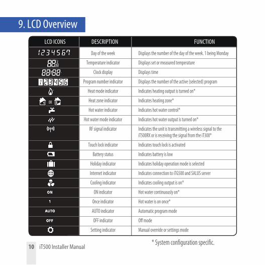
9. LCD Overview
10 iT500 Installer Manual
LCD ICONS DESCRIPTION FUNCTION
Day of the week Displays the number of the day of the week. 1 being Monday
Temperature indicator Displays set or measured temperature
Clock display Displays time
Program number indicator Displays the number of the active (selected) program
Heat mode indicator Indicates heating output is turned on*
Heat zone indicator Indicates heating zone*
Hot water indicator Indicates hot water control*
Hot water mode indicator Indicates hot water output is turned on*
RF signal indicator Indicates the unit is transmitting a wireless signal to the iT500RX or is receiving the signal from the iT300*
Touch lock indicator Indicates touch lock is activated
Battery status Indicates battery is low
Holiday indicator Indicates holiday operation mode is selected
Internet indicator Indicates connection to iTG500 and SALUS server
Cooling indicator Indicates cooling output is on*
ON indicator Hot water continuously on*
Once indicator Hot water is on once*
AUTO indicator Automatic program mode
OFF indicator Off mode
Setting indicator Manual override or settings mode
OR
* System configuration specific.
C
B
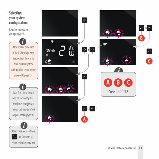
Selecting your system configurationBased on your system wiring on page 4.
1 2
ON1
AUTOOFF
AMPM
1 2
ON1
AUTOOFF
AMPM
1 2
ON1
AUTOOFF
AMPM
1 2
ON1
AUTOOFF
AMPM
1 2
ON1
AUTOOFF
AMPM
OR
OR
At any time press and hold
for 5 seconds to
return to the home screen.1 2
ON1
AUTOOFF
AMPM
i
i
Note! This menu should
only be entered by the
installer as changes can
have a detrimental effect
on your heating system.
i
If the iT500 is to be used
in the UK for single zone
heating then there is no
need to enter system
configuration setup, please
proceed to page 15.
i1 2
ON1
AUTOOFF
AMPM
1 2
ON1
AUTOOFF
AMPM
1 2
ON1
AUTOOFF
AMPM
iT500 Installer Manual 11
See page 12
A
A B C
Now that you have selected your system configuration you can continue with the rest of the installation setup.
1 2
ON1
AUTOOFF
AMPM 1 2
ON1
AUTOOFF
AMPM
OR
1 2
ON1
AUTOOFF
AMPM
OR
1 2
ON1
AUTOOFF
AMPM
1 2
ON1
AUTOOFF
AMPM 1 2
ON1
AUTOOFF
AMPM
OR
1 2
ON1
AUTOOFF
AMPM
1 2
ON1
AUTOOFF
AMPM
OR
1 2
ON1
AUTOOFF
AMPM
1 2
ON1
AUTOOFF
AMPM 1 2
ON1
AUTOOFF
AMPM
OR
1 2
ON1
AUTOOFF
AMPM
1 2
ON1
AUTOOFF
AMPM
OR
1 2
ON1
AUTOOFF
AMPM
+ +
1 2
ON1
AUTOOFF
AMPM
Select for heating application
Select for cooling application*
GMT Time setting**
Centigrade to Fahrenheit
Select for heating application
Select for cooling application*
GMT Time setting**
Centigrade to Fahrenheit
Select for heating application
Select for cooling application*
GMT Time setting**
Centigrade to Fahrenheit
* Cooling can only be selected if your system supports this.** Please refer to the following page for your region.
A B C
12 iT500 Installer Manual

10. European Time ZonesGMT
UKIRELANDPORTUGALICELAND*
RUSSIA*AUSTRIAPOLANDGERMANYCZECHSPAINFRANCEITALYSWITZERLANDLUXEMBOURGHOLLAND
BELGIUMDENMARKSWEDENNORWAYMALTACROATIASERBIABOSNIASLOVENIA
ESTONIATURKEYCYPRUSGREECEROMANIARUSSIAUKRAINE
BULGARIALITHUANIABELARUS*FINLANDMOLDOVALATVIA
GMT+1 Hour GMT+2 Hour GMT+3 Hour
The countries marked with * do not observe Daylight Saving Time
iiT500 Installer Manual 13

Now that you have selected your system configuration you can continue with the rest of the installation setup.DST (daylight saving time) ON will automatically change your time from summer to winter.
+ +A B C
1 2
ON1
AUTOOFF
AMPM
1 2
ON1
AUTOOFF
AMPM
1 2
ON1
AUTOOFF
AMPM
14 iT500 Installer Manual
11. Pairing the iT500 with the iT500RX Receiver
1 2
ON1
AUTOOFF
AMPM 1 2
ON1
AUTOOFF
AMPM
OR
1 2
ON1
AUTOOFF
AMPM 1 2
ON1
AUTOOFF
AMPM
OR
1 2
ON1
AUTOOFF
AMPM 1 2
ON1
AUTOOFF
AMPM
OR

1 2
6
Using a paper clip, insert into the hole marked SYNC at the bottom of the
iT500RX Receiver. Then work through the screen sequence shown on the next page.
The bottom switch will show a constant red light when the iT500RX Receiver is ready to
pair. Now go to the iT500 Thermostat.
When the iT500RX Receiver and the iT500 Thermostat are paired then the light will be green.
iT500 Installer Manual 15
1 2
ON1
AUTOOFF
AMPM1 2
ON1
AUTOOFF
AMPM
+
Press
to return to home screen. 1 2
ON1
AUTOOFF
AMPM
1 2
ON1
AUTOOFF
AMPM
OR1 2
ON1
AUTOOFF
AMPM
3
54
FAILSAFE MODE: In the event of RF signal loss, your system will be switched on for 4 minutes, then off for 11 minutes. If you want to disable FAILSAFE MODE when RF link has been lost then move the
slide switch on the iT500RX to either the manual or off position.
i
16 iT500 Installer Manual
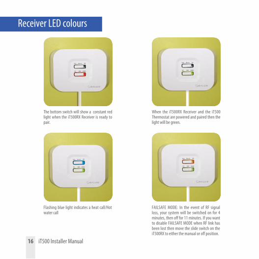
The bottom switch will show a constant red light when the iT500RX Receiver is ready to pair.
When the iT500RX Receiver and the iT500 Thermostat are powered and paired then the light will be green.
Flashing blue light indicates a heat call/Hot water call
FAILSAFE MODE: In the event of RF signal loss, your system will be switched on for 4 minutes, then off for 11 minutes. If you want to disable FAILSAFE MODE when RF link has been lost then move the slide switch on the iT500RX to either the manual or off position.
Receiver LED colours

3 4 5
1 2 3
12. Fitting the wall bracket and mounting the iT300
Remove the battery cover on the back of the iT300 unit.
Insert the 2x AAA batteries supplied into the iT300 unit.
Replace the battery cover.
Attach the wall mounting bracket to a suitable wall using the fittings supplied.
Note: iT300 purchased separately. Can only be used if your system supports two central heating zones. See pages 4 and 5.
Align the grooves on the back of the iT300 unit and slide onto the bracket.
Once in place, ensure the unit is securely seated on the bracket.
Used for 2 central heating
zones only
i
iT500 Installer Manual 17

1 2
13. Pairing the iT300 to the receiver
To pair the iT300 to the receiver, insert a paperclip or similar object into the hole on
the left hand side of the iT300 for 2 seconds.
A red light will flash in the top right hand corner of the iT300.
The iT500 has successfully paired with the iT300 when the antenna stops flashing.
Please note the red LED on the iT300 will continue to flash and eventually timeout.
The iT300 should be installed in the area of the house that the second zone will be controlled from, ie. Upstairs.
i
1 2
ON1
AUTOOFF
AMPM1 2
ON1
AUTOOFF
AMPM
+
1 2
ON1
AUTOOFF
AMPM Press
to return to home screen. 1 2
ON1
AUTOOFF
AMPM
1 2
ON1
AUTOOFF
AMPM
OR
3
4 5 6
18 iT500 Installer Manual

14. Registering and operating your iT500 online
Go to the SALUS controls website. www.salus-controls.com and select your relevant country
1
© Salus Controls 2012 Privacy Policy Disclaimer Site Map
Click on the register iT500 icon on the left hand side of your country’s website
2
iT500 Installer Manual 19

Click on REGISTER Fill in the online form and click REGISTER
4
The above screen will show and a confirmation email will be sent to you
5
14. Registering and operating your iT500 online
20 iT500 Installer Manual
3

14. Registering and operating your iT500 online
© Salus Controls 2012 Privacy Policy Disclaimer Site Map
Now use your username and password to log in.
You will receive a confirmation email. Click on the link to complete your registration.
© Salus Controls 2012 Privacy Policy Disclaimer Site Map© Salus Controls 2012 Privacy Policy Disclaimer Site Map
Your iT500 will appear as above and is now ready to be controlled or viewed via your PC or Smartphone. Just click on the iT500 icon on your PC.
Enter the iT500 STA number (Please refer to page 8). Then press REGISTER.
6 7
8 9
iT500 Installer Manual 21

15. Download Smartphone App
www.salus-controls.com
Once you have registered your iT500 online you can also download the smartphone App from the iPhone App Store or the Android App Store depending on which kind of Smartphone you are using. Find the iT500 App on the App Store and click download. The App will automatically download to your Smartphone and once downloaded you can begin controlling your iT500 Thermostat.
Go to the salus-controls.com website.
Click on the relevant App Store Icon.
Find the SALUS iT500 App and click download.
22 iT500 Installer Manual

Enter your user ID and password. Press
When you first open the iT500 App your iT500 will appear in the device list and you can begin controlling it with your Smartphone.
If you add more than 1 iT500 to your device list, you may wish to rename the iT500 to “DOWNSTAIRS” for example. Click onand enter a new name.
If you forget your password, follow the on screen instructions.
For full information on PC and Smartphone operation please refer to the user manual.
i
iT500 Installer Manual 23
16. Adding or renaming the iT500 in your device list

24 iT500 Installer Manual
Trouble shooting
Q. Can I operate the heating using the iT500 unit if I have no internet connection?A. Yes, most functions can be operated from the iT500 unit.
Q. Why do my iT500 buttons not work?A. Check that the screen lock is not active. If active, there will be a padlock visible in the top of the LCD. Disable by pressing and holding top two left keys on the iT500.
Q. Why does my heating never come on?A. Check that the iT500 is in AUTO mode, ‘AUTO’ should be visible at the bottom right on display. If showing ‘OFF’ press the TICK and SETTINGS buttons, then use the UP/DOWN arrow keys to change OFF to AUTO then TICK to confirm.
Q. I’ve tried doing the software upgrade (Green Button appeared on the iT500 web page) but it failed...A. Check the gateway is plugged into the router and it has a green light.A. Position the iT500 within 1 meter of the SALUS Gateway unit.A. If you receive the message ‘Failed’ please try running the OTA again. (Due to internet speed this may take several attempts)
Q. Where do I download my Smartphone app to control the iT500?A. If you have an iPhone, please search for iT500 on the app store, if you have an Android; search for iT500 on Google play.
Q. What does the Smartphone App do?A. It lets you control the iT500 remotely over the internet. You have full remote access to your heating control giving both temporary and program changes.

iT500 Installer Manual 25
Trouble shooting
Q. I can’t access my iT500 on my PC or Smartphone after registering it?A. Check you received your confirmation email from SALUS and clicked on it.A. Check you entered the correct email and password as used on registration.A. Ensure you added your device STA number which is located in the battery compartment of the iT500. You should see an image of your device after log-in, click on it to access.
Q. I have installed the device and registered online but my heating is not coming on.A. Check that the top slide switch on the receiver unit is in the AUTO position.A. Perform a quick installation check by putting the top slide switch to Manual position, and the bottom slide switch to CH. The boiler should fire, if not the iT500 receiver may be wired incorrectly. Please contact your installer.
Q. My receiver has a flashing blue light... what is that?A. A flashing Blue light is normal indication that the iT500 thermostat is asking for heat and the boiler should be on.
Q. My receiver has a flashing Yellow light... what is that?A. A flashing Yellow light is fault indication. The iT500 receiver unit has lost communication with the thermostat. Check the thermostat distance from its receiver, and check for major metalwork in its communication path (such as fridge/freezers). Reposition the thermostat to improve communication. Once it establishes communication again the fault will clear automatically.

26 iT500 Installer Manual
Trouble shooting
Q. The App says my iT500 is OFFLINE and my iT500 does not have the internet globe indicator on the screen, why is this?A. Check that you have the power supply turned ON to the gateway and it has a steady green light showing. The green light indicates you are connected to the SALUS server.A. If you have all the above, remove a battery from the iT500 and replace after 10 seconds. This will reboot the iT500 and bring you back online.
Q. I’ve just plugged the SALUS gateway into my Belkin and the gateway has a solid RED light, what is this? A. The gateway must be connected to a network that has DHCP enabled, it must be connected to a network that has the firewall ports 80 (UDP/TCP) and 2165 (TCP) open. (You may need to contact your internet provider to assist you changing your router settings.)
Q. I have a new BT Hub 5 router and the gateway has a solid red light.A. BT Hub 5 uses ports 3 and 4.
Q. Just had the iT500 installed and my heating isn’t coming on?A. Have you paired the thermostat with the receiver, please see page 15 in the installer manual on how to do this.

17. WarrantySALUS Controls warrants that this product will be free from any defect in materials or workmanship, and shall perform in accordance with its specification, for a period of two years from the date of installation. SALUS Controls sole liability for breach of this warranty will be (at its option) to repair or replace the defective product.
Customer Name: .............................................................................................................................
Customer Address: ..........................................................................................................................
............................................................................... Post Code: ........................................................
Tel No: ........................................................ Email: .........................................................................
Engineers Company: .......................................................................................................................
Tel No: ......................................................... Email: ........................................................................
Installation Date: ..........................................................................................................................
....
Engineers Name: ............................................................................................................................
iT500 Installer Manual 27

www.salus-controls.com
SALUS Controls plcSALUS HouseDodworth Business Park South,Whinby Road,Dodworth, Barnsley S75 3SPUK.
SALES: T: +44 (0) 1226 323961 E: [email protected]
TECHNICAL: T: +44 (0) 1226 323961 E: [email protected]
Issue Date: Sept 2013
Maintaining a policy of continuous product development SALUS Controls plc reserve the right to change specification, design and materials of products listed in this brochure without prior notice.
SALUS Controls is a member of the Computime Group
00086/2