
ISWC 2009 Workshop 26 October 2009, Virginia, USA
101
8th International Semantic Web Conference (ISWC 2009) 25-29 October 2009, Virginia, USA 5th International Workshop on Semantic Web Enabled Software Engineering SWESE 2009 : ISWC 2009 Workshop 26 October 2009, Virginia, USA Edited by: Elisa F. Kendall Jeff Z. Pan Marwan Sabbouh Ljiljana Stojanovic Yuting Zhao
Transcript of ISWC 2009 Workshop 26 October 2009, Virginia, USA

8th International Semantic Web Conference (ISWC 2009)
25-29 October 2009, Virginia, USA
5th International Workshop
on Semantic Web Enabled Software Engineering
SWESE 2009 :
ISWC 2009 Workshop
26 October 2009, Virginia, USA
Edited by: Elisa F. Kendall
Jeff Z. Pan
Marwan Sabbouh
Ljiljana Stojanovic
Yuting Zhao

i
Workshop Organisers
Elisa F. Kendall, Sandpiper Software, Inc. US.
Jeff Z. Pan, University of Aberdeen, UK.
Marwan Sabbouh, MITRE Corporation. US.
Ljiljana Stojanovic, FZI, Germany.
Yuting Zhao, University of Aberdeen, UK.
Program Committee Uwe Assman (DE), Technical University of Dresden
Colin Atkinson (DE), University of Mannheim
Ken Baclawski (US), Northeastern University
Roberta Cuel (IT), University of Trento
Jin Song Dong (SG), National University of Singapore
Jürgen Ebert (DE), University of Koblenz
Andreas Friesen (DE), SAP Research
Dragan Gasevic, (CA) Simon Fraser University Surrey
Michael Goedicke (DE), University of Essen
Jakob Henriksson (US), Intelligent Automation, Inc.
Mitch Kokar (US), Northeastern University
Harald Kühn (AT), BOC
David Martin (US), SRI International
Krzysztof Miksa (PL), Comarch
Jishnu Mukerji (US), Hewlett-Packard Company
Daniel Oberle (DE), SAP Research
Fernando Silva Parreiras (DE), University of Koblenz
Yuan Ren (UK), University of Aberdeen
Dave Reynolds (UK), HP Labs
Michael K. Smith (US), Electronic Data System
Hai Wang (UK), Aston University
Andrea Zisman, (UK) City University, London
Sponsorshop The workshop is being held in cooperation with a prominent
network of excellence and is meant to act as a focal point
for joint interests and future collaborations. SWESE2009 is
sponsored by the MOST project (EU ICT 2008-216691).

ii
Introduction
The advent of the World Wide Web has led many corporations to web-enable their
business applications and to the adoption of web service standards in middleware
platforms. Marking a turning point in the evolution of the Web, the Semantic Web is
expected to provide more benefits to software engineering. Over the past five years there
have been a number of attempts to bring together languages and tools, such as the Unified
Modelling Language (UML), originally developed for Software Engineering, with
Semantic Web languages such as RDF and OWL. The Semantic Web Best Practice and
Deployment Working Group (SWBPD) in W3C included a Software Engineering Task
Force (SETF) to investigate potential benefits. A related international standardisation
activity is OMG's Ontology Definition Metamodel (ODM), which was formally adopted
in October 2006, and finalized in December 2008. Another interesting question is how to
use ontology to improve guidance and traceability in software development.
It has been argued that the advantages of Semantic Web Technologies in software
engineering include reusability and extensibility of data models, improvements in data
quality, and discovery and automated execution of workflows. According to SETF's note
A Semantic Web Primer for Object-Oriented Software Developers, the Semantic Web
can serve as a platform on which domain models can be created, shared and reused.
However, are there other potential benefits in the use of Semantic Web concepts in the
field of Software Engineering? Could the Web-based, semantically rich formality of
OWL be combined with emerging model driven development tools such as the Eclipse
Modelling Framework to provide some badly needed improvements in both the process
and product of software development activities? What is it about the amalgamation of
OWL, UML and MDA methodology that could make a difference? Certainly, there
appear to be a number of strong arguments in favour of this approach but consensus on
the best way forward, if there is indeed a way forward at all has not yet formed. This
workshop seeks to build on prior events that have begun to explore and evaluate this
important area.
Copyright © 2009 for the individual papers by the papers' authors.
Copying permitted for private and academic purposes. Re-publication of
material from this volume requires permission by the copyright owners.
This volume is published by its editors.

iii
Table of Contents
Validating Process Refinement with Ontologies
Yuan Ren, Gerd Gröner, Jens Lemcke, Tirdad Rahmani, Andreas Friesen,
Yuting Zhao, Jeff Z. Pan and Steffen Staab ………………………………………. 1 - 15
Implementing Semantic Web applications: reference architecture and challenges
Benjamin Heitmann, Sheila Kinsella, Conor Hayes and Stefan Decker ………… 16 - 30
Fly-By-OWL: A Framework for Ontology Driven E-commerce Websites
Azhar Jassal and David Bell ………..……………………………………………. 31 - 44
How To Simplify Bulding Semantic Web Applications
Matthias Quasthoff, Harald Sack and Christoph Meinel ……………………...…. 45 - 57
Ontology-Driven Software: What We Learned From Using Ontologies As Infrastructure
For Software
Csongor I Nyulas, Natalya F Noy, Michael V Dorf, Nicholas Griffith
and Mark Musen ……………………………………………………………….… 58 - 72
Integrating Linked Data Driven Software Development Interaction into an IDE
Aftab Iqbal, Oana Ureche and Michael Hausenblas ………………………...……73 - 85
Data Modeling and Harmonization with OWL: Opportunities and Lessons Learned
John McCarthy, Elisa Kendall, Warzel Denise, Bruce Bargmeyer,
Harold Solbrig, Kevin Keck and Fred Gey ………………………………………. 86 - 97

Validating Process Refinement with Ontologies?
Yuan Ren1, Gerd Groener2, Jens Lemcke3, Tirdad Rahmani3, Andreas Friesen3,Yuting Zhao1, Jeff Z. Pan1 and Steffen Staab2
1University of Aberdeen, 2University of Koblenz-Landau, 3SAP AG
Abstract. A crucial task in process management is the validation ofprocess refinements. A process refinement is a process description in amore fine-grained representation. The refinement is with respect to eitheran abstract model or a component’s principle behaviour model. We defineprocess refinement based on the execution set semantics. Predecessor andsuccessor relations of the activities are described in an ontology in whichthe refinement can be validated by concept satisfiability checking.
1 Introduction
With the growing interest about applying semantic web technologies on businessprocess modelling, many frameworks and ontological models have been proposedto facilitate a more unified semantic representation [5, 6].
In model-driven software development, process models are usually createdand refined on different levels of abstraction. A generic process describes the corefunctionality of an application. A refinement is a transformation of a processinto a more specific process description which is developed for a more concreteapplication and based on more detailed process behaviour knowledge. In this pro-cedure, the refined process should refer to the intended behaviour of the abstractprocess and satisfies behaviour constraints. To check and ensure the consistencyof refinement becomes a crucial issue in process management. Currently, suchconsistency check is mainly done manually and few methods have been investi-gated to help automation. Hence the validation is error-prone, time-consumingand increases the costs during the development cycle.
In this paper, we use execution set semantics to describe two types of processrefinements and present an ontological approach to represent and check them.We first apply topological transformations to reduce the refitment checking w.r.t.execution set semantics into checking of predecessors and successors of processelements. Then we encode process models into OWL DL ontologies. Finally weshow that the refinement checking on the process models can be accomplished byconcept ussatisfiability checking in the ontology. We implemented our approachand conducted performance evaluation on a set of randomly generated processmodels. Experiment results showed that, 80% of the refinement validation tasks
? This work has been supported by the European Project Marrying Ontologies andSoftware Technologies (EU ICT 2008-216691).
SWESE 2009: 5th International Workshop on Semantic Web Enabled Software Engineering
1
can be performed within 1s, which is significantly faster than manually consistencychecking and the correctness of the validation is guaranteed.
The rest of the paper is organised as follows: in Sec.2 we define the problemof process refinement with its graphical syntax, semantics and mathematicalfoundation. The representation and validation of processes with the correspondingexecution constraints is demonstrated in Sec.3. In Sec.4 we present the evaluationsand in Sec.5 we review related works and conclude the paper.
2 Preliminary
In this section, we introduce preliminary knowledge about process models, processrefinement w.r.t. execution set semantics and DL-based ontologies.
Syntax of Process Models A process model—or short: process—is a non-simple directed graph P = 〈E, V〉 without multiple edges between two vertices.As a graphical representation, we use the business process modelling notation(BPMN: http://www.bpmn.org/) due to its wide industry adoption. However,we consider a normal form of process models for the sake of this paper as opposedto the full set of partly redundant constructs in BPMN.
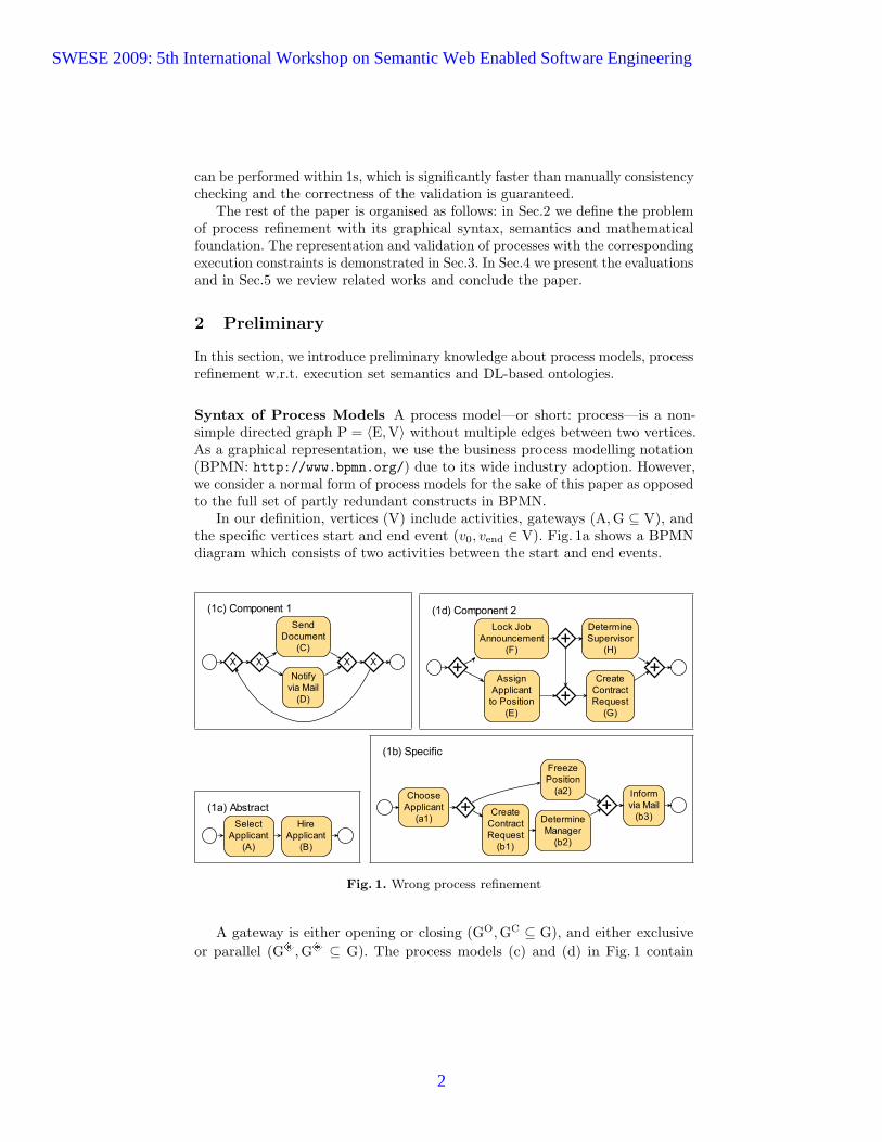
In our definition, vertices (V) include activities, gateways (A, G ⊆ V), andthe specific vertices start and end event (v0, vend ∈ V). Fig. 1a shows a BPMNdiagram which consists of two activities between the start and end events.
�������������
� �
����������
��
���������������
��
�������������
��������������������� �
��
����������������������
�����������������������������
�������������������� �
�����������
�������������
��������������
����������
�������������� ��
�
������������������
���������������������� ��
���������������� ��
������ !!����������
Fig. 1. Wrong process refinement
A gateway is either opening or closing (GO, GC ⊆ G), and either exclusiveor parallel (G , G ⊆ G). The process models (c) and (d) in Fig. 1 contain
SWESE 2009: 5th International Workshop on Semantic Web Enabled Software Engineering
2

exclusive and parallel gateways, respectively. We call a process normal if it doesnot contain parallel gateways (G = ∅)—as, for example, process model (c).
The edge set (E) is a binary relation on V. We define the predecessor and thesuccessor functions of each v1 ∈ V as follows: pre(v1) := {v2 ∈ V | (v2, v1) ∈ E},suc(v1) := {v3 ∈ V | (v1, v3) ∈ E}. The start (end) event has no predecessor(successor): |pre(v0)| = |suc(vend)| = 0 and exactly one successor (predecessor):|suc(v0)| = |pre(vend)| = 1. Each open gateway o ∈ GO (close gateway c ∈ GC)has exactly one predecessor (successor): |pre(o)| = |suc(c)| = 1. Each activitya ∈ A has exactly one predecessor and successor: |pre(a)| = |suc(a)| = 1. We canthen construct gateway-free predecessor and successor sets as follows:
PS(v1) := {v2 ∈ A | v2 ∈ pre(v1) or ∃u ∈ G s.t. u ∈ pre(v1) and v2 ∈ PS(u)}SS(v1) := {v3 ∈ A | v3 ∈ suc(v1) or ∃u ∈ G s.t. u ∈ suc(v1) and v3 ∈ SS(u)}
These two definitions make gateways “transparent” to ordering relations. Forexample in Fig.1b, SS(a1) = {b1, a2}, in Fig.1c, PS(C) = {C, D}.
Execution Set Semantics of Process Models We define the semantics of aprocess model using the execution set semantics [18]. An execution is a propersequence of activities (ai ∈ A): [a1a2 . . . an]. A proper sequence is obtained bysimulating token flow through a process model. A token is associated to exactlyone vertex or edge. Initially, there is exactly one token, associated to the startevent. Tokens can be created and consumed following the rules below. Whenevera token is created in an activity, the activity is appended to the sequence. Exactlyone of the following actions is performed at a time:
– For creating a token in an activity or in the end event v1 ∈ A∪{vend}, exactlyone token must be consumed from the incoming edge (v2, v1) ∈ E.
– Exactly one token must be removed from an activity or from the start eventv1 ∈ A ∪ {v0} in order to create one token in the leaving edge (v1, v2) ∈ E.
– For creating a token in a parallel close gateway g ∈ (G ∩GC), exactly onetoken must be consumed from every incoming edge (v, g) ∈ E.
– For creating a token in an exclusive close gateway g ∈ (G ∩GC), exactlyone token must be consumed from exactly one incoming edge (v, g) ∈ E.
– Exactly one token must be removed from a close gateway g ∈ GC in order tocreate one token in the leaving edge (g, v) ∈ E.
– For creating a token in an open gateway g ∈ GO, exactly one token must beconsumed from the incoming edge (v, g) ∈ E.
– Exactly one token must be removed from a parallel open gateway g ∈(G ∩GO) in order to create one token in each leaving edge (g, v) ∈ E.
– Exactly one token must be removed from an exclusive open gateway g ∈(G ∩GO) in order to create one token in exactly one leaving edge (g, v) ∈ E.
If none of the above actions can be performed, simulation has ended. The resultis a proper sequence of activities—an execution. It is to be noted that each
SWESE 2009: 5th International Workshop on Semantic Web Enabled Software Engineering
3

execution is finite. However, there may be an infinite number of executions for aprocess model. The execution set of a process model P , denoted by ESP , is the(possibly infinite) set of all proper sequences of the process model.
For example, ES1a for process (a) in Fig. 1 is {[AB]}: first A, then B (forbrevity, we refer to an activity by its short name, which appears in the diagramsin parenthesis). Process (b) contains parallel gateways ( ) to express that someactivities can be performed in any order: ES1b = {[a1a2b1b2b3], [a1b1a2b2b3],[a1b1b2a2b3]}. Exclusive gateways ( ) are used in process (c) both to choosefrom the two activities and to form a loop: ES1c = {[C], [D], [CC], [CD], [DC],[DD], . . .}. Process (d) shows that gateways can also occur in a non-block-wisemanner: ES1d = {[EFGH], [EFHG], [FHEG], [FEGH], [FEHG]}.
Correct Process Refinement For refinement validation we have to distin-guish between horizontal and vertical refinement. A horizontal refinement is atransformation from an abstract to a more specific model which contains thedecomposition of activities. A vertical refinement is a transformation from aprinciple behaviour model of a component to a concrete process model for anapplication. The validation have to account for both refinements.
Fig. 1 shows a refinement horizontally from abstract to specific while verticallycomplying with the components’ principle behaviour. In our example scenario,Fig. 1a is drawn by a line of business manager to sketch a new hiring process.Fig. 1b is drawn by a process architect who incrementally implements the sketchedprocess. Fig. 1c and d are the principle behaviour models of different components.
To facilitate horizontal validation, the process architect has to declare whichactivities of Fig. 1b implement which activity of Fig. 1a: hori(a1) = hori(a2) = A,hori(b1) = hori(b2) = hori(b3) = B. For vertical validation, the process architectneeds to link activities of Fig. 1b to service endpoints given in Fig. 1c and d:vert(a1) = E, vert(a2) = F, vert(b1) = G, vert(b2) = H, vert(b3) = D.
Correct horizontal refinement. We say that a process Q is a correct horizontalrefinement of a process P if ESQ ⊆ ESP after the following transformations.
1. Renaming. Replace all activities in each execution of ESQ by their origina-tors (function hori()). Renaming the execution set {[a1a2b1b2b3], [a1b1a2b2b3],[a1b1b2a2b3]} of Fig. 1b yields {[AABBB], [ABABB], [ABBAB]}.
2. Decomposition. Replace all sequences of equal activities by a single activityin each execution of ESQ. For Fig. 1b this yields {[AB], [ABAB]}.
As {[AB]} 6⊇ {[AB], [ABAB]}, Fig. 1b is a wrong horizontal refinement of Fig. 1a.The cause is the potentially inverted order of AB by b1a2 or b2a2 in Fig. 1b.
Correct vertical refinement. We say that a process Q is a correct vertical refine-ment of a process P if ESQ ⊆ ESP after the following transformations.
1. Renaming. Replace all activities in each execution of ESQ by their grounds(function vert()). Renaming the execution set {[a1a2b1b2b3], [a1b1a2b2b3],[a1b1b2a2b3]} of Fig. 1b yields {[EFGHD], [EGFHD], [EGHFD]}.
SWESE 2009: 5th International Workshop on Semantic Web Enabled Software Engineering
4

2. Reduction. Remove all activities in each execution of ESQ that do notappear in P . For our example, reduction with respect to Fig. 1c yields {[D]}.Reduction with respect to Fig. 1d yields {[EFGH], [EGFH], [EGHF]}.
Fig. 1b is a correct vertical refinement of Fig. 1c because {[C], [D], [CC], [CD], [DC],[DD], . . .} ⊇ {[D]} and a wrong vertical refinement of Fig. 1d because {[EFGH],[EFHG], [FHEG], [FEGH], [FEHG]} 6⊇ {[EFGH], [EGFH], [EGHF]}. The cause for thewrong refinement is the potentially inverted execution of FG by b1a2 in Fig. 1b.
As enumerating the execution sets for validation is infeasible, our solutionworks with descriptions in ontology instead of using the execution sets themselves.
Description Logics and Ontologies DL-based ontologies have been widelyapplied as knowledge formalism for the semantic web. An ontology usually consistsof a terminology box (TBox) and an assertion box (ABox). In TBox the domainis described by concepts and roles with DL constructs. In this paper, we use DLALC. Its concepts are inductively defined by following constructs:
>,⊥, A,¬C, C uD,C tD,∃r.C, ∀r.D
where > is the super concept of all concepts; ⊥ means nothing; A is an atomicconcept; C and D are general concepts and r is an atomic role. In DL, thesubsumption between two concepts C and D is depicted as C v D. If two conceptsmutually subsume each other, they are equivalent, depicted by C ≡ D. When aconcept can not be instantiated in any model, i.e., C v ⊥, it is unsatisfiable. Twoconcepts are disjoint if C v ¬D. In this paper we write Disjoint(C1, C2, . . . , Cn)to denote that all these concepts disjoint with one another.
3 Validation with Ontologies
In this section, we present our solution of validating process refinement indetail. We first eliminate all the parallel gateways in a process, then translatesuch a process into ontologies based on the predecessor and successor sets ofactivities, finally we show that the refinement checking can be reduced to conceptunsatisfiability checking
3.1 Process Transformation
As we can see from ES1c, the execution ordering relations between successors ofsome g ∈ GO are implicit in the original process. For example, b1 and a2 doesnot have any explicit edge, the semantics of parallel gateway still implies thatb1a2 or a2b1 must appear in some execution. In order to make such relationsexplicit, we eliminate all the parallel gateways while retain the execution set. Ourstrategy is to generate exclusive gateways to represent the executions.
Given a process P , its normal n(P ) can be obtained as follows:
SWESE 2009: 5th International Workshop on Semantic Web Enabled Software Engineering
5

1. Repeatedly replace each penning-parallel gateway g by an opening-exclusivegateway e. For each v ∈ suc(e), construct a new penning-parallel gateway g′
with pre(g′) = v, suc(g′) = suc(v) ∪ suc(e) \ {v} and then make suc(v) = g′.2. Remove all the edges from an opening- to a closing-parallel gateway.3. If an opening-gateway has only one successor, remove the gateway4. If an closing-gateway has only one predecessor, remove the gateway
In step 1 direct successors of parallel gateways are “pulled” out of the gate-way. Here a loop block is considered as a single successor. In this procedure, aparallel gateway with n successors is transformed into n parallel gateways with nsuccessors but one of the successive sequence is shortened by one successor. Dueto the finite length of these sequences, this replacement always terminates. Step2 then reduces the number of successors for these remaining parallel gatewaysby removing “empty” edges. Step 3 and 4 finally remove the gateways. When agateway is removed, its predecessors and successors should be directly connected.
It’s obvious that this normalisation will always result in a normal process. Anexample of normalisation of Fig.1b and Fig.1d can be seen in Fig.2.
The size of n(P ) can be exponentially large w.r.t. P in worst case: suppose Pcontains only a pair of parallel gateways with n sequences of one activity, thenn(P ) will contains a pair of exclusive gateways with n! sequences of n activities.
��������������� �������
�
�����
����� � �����
�����
� �����
�����
����� �����
�����
�����
����������������� �������
�
����
����
�
����
���� �
����
���
� ���
���
�
�������
���
����
���� ��
����
Fig. 2. Transformation to execution diagrams for Fig. 1b and d
In normalisation, some activities will be duplicated in the process. Theseduplications have different predecessors (successors). We distinguish them byan additional numerical subscript. We depict such a transformed process n(P )with distinguished activities by P ?. Obviously, ESP ? is the same as ESn(P ) afterreplacing all the distinguished activities by their original names. Thus, relationbetween two execution sets can be characterised by the following theorem:
Theorem 1. Given two processes P = 〈EP , VP 〉 and Q = 〈EQ, VQ〉, ESQ ⊆ESP iff ∀ai ∈ AQ? , there exists some aj ∈ AP ? such that PSQ?(ai) ⊆ PSP ?(aj)and SSQ?(ai) ⊆ SSP ?(aj).
Proof. (1) For the → direction the lhs ESQ ⊆ ESP holds. We demonstrate thesubsumption for PS. For an arbitrary activity ai ∈ AQ? , the activity ai
′ is thecorresponding activity before normalisation (i.e. without additional subscripts).
SWESE 2009: 5th International Workshop on Semantic Web Enabled Software Engineering
6

The activity aj′ is the originator or ground activity of ai
′ in P after renaming andaj ∈ AP ? is the the corresponding activity after normalization of P . From theprerequisite it directly follows that the predecessors of ai ∈ AQ? are predecessorsof aj in Q?. The subsumption of the successor set is demonstrated likewise.(2) To prove the other direction we assume that the rhs holds. Consider anexecution s ∈ ESQ we demonstrate that s ∈ ESP . For each activity ai
′ of anarbitrary execution s ∈ ESQ the corresponding activity ai ∈ AQ? is receivedafter normalization. From the rhs it follows that there exists an activity aj ∈ AP ?
so that each predecessor of ai is also a predecessor of aj in P ? and likewise forthe successors of ai. After activity renaming and demonstrating for all activitiesof each execution of ESQ the inclusion of the lhs follows.
Therefore, we reduce the process refinement w.r.t. execution set semanticsinto the subsumption checking of finite predecessor and successor sets. We thenshow that the transformation operations of execution sets can be equivalentlyperformed on the its process model and the predecessor and successor sets:
– Reduction on the process diagrams has the same effect on the executionsets. That means, given a component model P and a process model Q, if wereduce Q into Q′ by removing all the activities that do not appear in P , andconnect their predecessors and successors directly, the resulting ESQ′ will bethe same as the reduced ESQ with respect to P .
– Renaming can also be directly performed on the process diagram, i.e.ESP [a → A] = ESP [a→A]. Thus, the renaming can be performed on thepredecessor and successor sets as well, i.e. PSP (x)[a → A] = PSP [a→A](x)(SSP (x)[a→ A] = SSP [a→A](x)).
– Decomposition can be done on the predecessor and successor sets as well.Theorem 1 shows that the subsumption of execution sets can be reduced tosubsumption of predecessor and successor sets. Decomposition means, anactivity x can go from not only predecessors of x, but also another appearanceof x, and can go to not only successors of x, but also another appearance ofx. Any sequence of x in the execution will be decomposed.
Thus, for horizontal refinement, we can first obtain the predecessor and suc-cessor sets of activities, and then perform the Renaming and Decompositionon these sets, and then check the validity. For vertical refinement, we can firstperform the Reduction on processes, then obtain the predecessor and successorsets and perform the Renaming on these sets, and finally check the validity.
In this paper, we perform Reduction directly on the a process P andobtain the predecessor and successor sets from P ?, then encode Renaming andDecomposition into ontology and check the validity with reasoning.
3.2 Refinement representation
In this section we represent the predecessor and successor sets of activities withontologies. In such ontologies, activities are represented by concepts. The prede-cessors/successors relations are described by two roles from and to, respectively.
SWESE 2009: 5th International Workshop on Semantic Web Enabled Software Engineering
7
On instance level, these two roles should be inverse role of each other. Howeverthis is not necessary in our solution. Composition of activities in horizontal refine-ment is described by role compose. Grounding of activities in vertical refinementis described by role groundedTo. To facilitate the ontology construction, fouroperators are defined for pre- and post- refinement process:
Definition 1. : Given S a predecessors or successors set, we define four operatorsfor translations as follows:
Pre-refinement-from operator Prfrom(S) = ∀from.⊔
x∈S xPre-refinement-to operator Prto(S) = ∀to.
⊔y∈S y
Post-refinement-from operator Psfrom(S) =d
x∈S ∃from.xPost-refinement-to operator Psto(S) =
dy∈S ∃to.y
The effect of the above operators in refinement checking can be characterisedby the following theorem:
Theorem 2. PSQ(a) ⊆ PSP (a) iffDisjoint(x|x ∈ AP ∪ AQ) infers that Prfrom(PSP (a))uPsfrom(PSQ(a)) issatisfiable.
SSQ(a) ⊆ SSP (a) iffDisjoint(x|x ∈ AP ∪AQ) infers that Prto(SSP (a))uPsto(SSQ(a)) is satisfiable.
For sake of a shorter presentation, we only prove the first part of the theorem.The proof for the second part is appropriate to the first part.
Proof. (1) We demonstrate the → direction with a proof by contraposition.The disjointness of activities holds. Supposed the rhs is unsatisfiable, i.e.Prfrom(PSP (a))uPsfrom(PSQ(a)) is unsatisfiable. Obviously, both concept def-initions on its own are satisfiable, since Prfrom(PSP (a)) is just a definition withone all-quantified role followed by a union of (disjoint) concepts. The conceptdefinition behind this expression is ∀from.
⊔x∈PSP (a) x which restricts the range
of from to all concepts (activities) of PSP (a). Psfrom(PSQ(a)) is a conceptintersection which only consists of existential quantifiers and the same fromrole. This definition is also satisfiable. Therefore the unsatisfiability is caused bythe intersection of both definitions. In Psfrom(PSQ(a)) the same role from isused and the range is restricted by Prfrom(PSP (a)). Therefore the contradictionis caused by one activity b ∈ PSQ(a) which is not in PSP (a), but this is acontradiction to the precondition PSQ(a) ⊆ PSP (a).(2) The ← direction can be proved similarly by contraposition.
Now we can represent horizontal and vertical refinements by ontologies:
Horizontal Refinement For conciseness of presentation, we always have apre-refinement process P and a post-refinement process Q and we refine oneactivity z of P in this step. z may have multiple appearances zj in P ?. For eachzj we define component zj ≡ ∃compose.zj . Simultaneous refinement of multipleactivities can be done in a similar manner of single refinement. Then we constructan ontology OP→Q with following axioms:
SWESE 2009: 5th International Workshop on Semantic Web Enabled Software Engineering
8

1. for each activity ai ∈ AQ? and hori(a) = zai v
⊔∃compose.zj
These axioms represent the composition of activities with concept sub-sumption, which realise Renaming in horizontal refinement. For example,b31 v ∃compose.B and a11 v ∃compose.A.
2. for each ai ∈ AQ? where a is not refined from zai vPrfrom(PSP ?(ai))[zj → component zj ],ai vPrto(SSP ?(ai))[zj → componennt zj ],These axioms represent the predecessor and successor sets of all the unre-fined activities in the pre-refinement process. Because in the post-refinementprocess, any activity refined from zj will be considered as a subconcept of⊔
component zj , we replace the appearance of each zj by correspondingcomponent zj . For example, Start v ∀to.component A.
3. for each zj ∈ AP ? ,component zj vPrfrom(PSP ?(zj)∪{component zj})[zj → componennt zj ],component zj vPrto(SSP ?(zj) ∪ {component zj})[zj → componennt zj ],These axioms represent the predecessor and successor sets of all the refinedactivities in the pre-refinement process. Due to the mechanism of Decompos-ing, we add corresponding component zj to their predecessor and successorsets, and replace the zj with component zj for the same reason as before.For example, component A v ∀from.(Start t component A).
4. for each ai ∈ AQ? ,ai vPsfrom(PSQ?(ai)),ai vPsto(SSQ?(ai)),These axioms represent the predecessor and successor sets of all the activitiesin the post-refinement process. For example, a22 v ∃from.b12, b23 v ∃to.a23.
5. Disjoint(ai|ai ∈ Q and Hori(a) = z)These axioms represent the uniqueness of all the sibling activities refinedfrom the same zj . For example, Disjoint(a11, a21, a22, a23)
6. Disjoint( all the activity in P , and all the component zj).This axiom represents the uniqueness of all the activities before refinement.For example, Disjoint(Start, End,A, B, component A, component B).
With the above axioms, ontology OP→Q is a representation of the horizontalrefinement from P to Q by describing the predecessor and successor sets ofcorresponding activities with axioms.
Vertical Refinement Similar as horizontal refinement, suppose we have prin-ciple behaviour model P and a concrete process model Q, which has alreadybeen reduced w.r.t P to eliminate ungrounded activities. Any activity in Q canbe grounded to some activity in P . Thus, after reduction, ∀a ∈ AP ,∃b ∈ AQ
that b is grounded to a, and vice versa. Therefore for each xj ∈ AP ? , we definegrounded xj ≡ ∃groundedTo.xj .Then we construct an ontology OP→Q withfollowing axioms:
1. for each activity ai ∈ AQ? and vert(a) = xai v
⊔∃groundedTo.xj
SWESE 2009: 5th International Workshop on Semantic Web Enabled Software Engineering
9

These axioms represent the grounding of activities by concept subsumption,which realise the Renaming in vertical refinement. For example, a11 v∃groundedTo.E, b11 v ∃groundedTo.F .
2. for each ai ∈ AP ?
grounded ai vPrfrom(PSP ?(ai))[xj → grounded xj ],grounded ai vPrto(SSP ?(a))[xj → grounded xj ],These axioms represent the predecessor and successor sets of all the activitiesin the pre-refinement process. Due the mechanism of Renaming we replaceall the xj ∈ AP ? by grounded xj . Because Decomposition is not neededin vertical refinement, we stick to the original predecessor and successor sets.These axioms become the constraints on the activities in Q?.
3. for each ai ∈ AQ? ,ai vPsfrom(PSQ?(ai)),ai vPsto(SSQ?(ai)),These axioms represent the predecessor and successor sets of all the activitiesin the post-refinement process. Notice that the ungrounded activities havebeen removed from the process.
4. for each x ∈ AP ,Disjoint(ai|ai ∈ Q? and vert(a) = x)These axioms represent the uniqueness of all the sibling activities refinedfrom the same x.
5. Disjoint(Start, End, all the grounded xj).This axiom represents the uniqueness of all the activities before refinement.For example, Disjoint(Start, End, grounded C, grounded D).
With above axioms, ontology OP→Q is a representation of the refinementfrom P to Q by describing the predecessor and successor sets of correspondingactivities with axioms.
In both horizontal and vertical refinement, the number of axioms are linearw.r.t. the size of P ? and Q?. The language is ALC.
3.3 Concept satisfiability checking
In ontology OP→Q, all the activities in Q? satisfy the ordering relations inP ? by satisfying the universal restrictions and satisfy the ordering relationsin Q? by satisfying existential restrictions. Given the uniqueness of concepts,the inconsistency between P ? and Q? will lead to unsatisfiability of particularconcepts. The relation between the ontology OP→Q and the validity of therefinement from P to Q is characterised by the following theorems:
Theorem 3. An execution path containing activity a in Q is invalid in therefinement from P to Q, iff there is some ai ∈ Q? such that OP→Q |= ai v ⊥.
Proof. For each a in Q the ontology OP→Q contains the axiomsa vPsfrom(PSQ(a)) and a vPsto(SSQ(a)). The axioms a vPrfrom(PSQ(a))and a vPrto(SSQ(a)) are derived from the axioms (item 1,2). Depending onthe refinement either the axioms a v ∃groundedTo.xj and grounded xj ≡
SWESE 2009: 5th International Workshop on Semantic Web Enabled Software Engineering
10

∃groundedTo.xj or a v ∃compose.zj and component zj ≡ ∃compose.zj are inthe ontology. (1) For the → direction the lhs holds, we demonstrate that a isunsatisfiable. Since a is invalid either PSQ(a) 6⊆ PSP (a) or SSQ(a) 6⊆ SSP (a).From Theorem 2 it follows that either Prfrom(PSP (a))uPsfrom(PSQ(a)) orPrto(SSP (a))uPsto(SSQ(a)) is unsatisfiable and therefore a is unsatisfiable sincea is subsumed. (2) The ← direction is proved by contraposition. Given a is unsat-isfiable in OP→Q. Assumed a is valid in the refinement then PSQ(a) ⊆ PSP (a)and SSQ(a) ⊆ SSP (a) holds. From Theorem 2 the satisfiability of Prto(SSP (a)),Prfrom(PSP (a)), Psfrom(PSQ(a)) and Psto(SSQ(a)) follows which leads to acontradiction to the satisfiability of a.
This theorem has two implications:
1. The validity of a refinement can be checked by the satisfiability of all thename concepts in an ontology;
2. The activities represented by unsatisfiable concepts in the ontology are thesource of the invalid refinement.
we check the satisfiability of the concepts to validate the process refinement.Every unsatisfiable concept is either an invalid refinement or related to an invalidrefinement.
With the help of reasoning, we can easily see that Fig.1b is an invalidhorizontal refinement w.r.t. Fig.1a: a22 v ∃from.b12, also a22 v ∃compose.Athus a22 v ∀from.(Start t component A). However, b12 disjoints with bothStart and component A therefore a22 is unsatisfiable. Similarly, we can detectthat b12, b23 and a23 are unsatisfiable. This implies the invalid routes in Fig.2aand further the invalid refinement of Fig.1b. Also, the vertical refinement w.r.t.Fig.1d is wrong while the vertical refinement w.r.t. Fig.1c is correct.
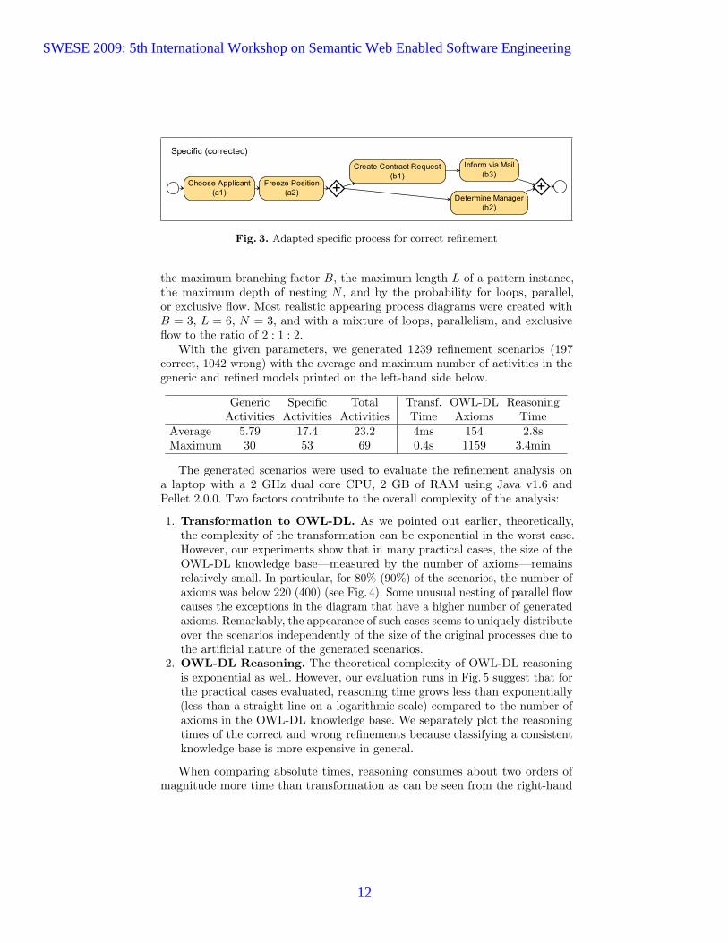
According to the underlying logic, reasoning complexity is ExpTime.Helped by our analysis, the process architect remodels their process (Fig. 3).
Now, the execution set of Fig. 3 is {[a1a2b1b2b3], [a1a2b2b1b3], [a1a2b1b3b2]}. Re-naming of Fig. 3’s execution set with respect to Fig. 1a yields {[AABBB]}. Afterdecomposition, we conclude that Fig. 3 correctly horizontally refines the processin Fig. 1a because {[AB]} ⊇ {[AB]}. As for validating vertical refinement with thecomponent models, renaming yields {[EFGHD], [EFHGD], [EFGDH]}. After reduc-tion with respect to Fig. 1c and Fig. 1d, we conclude that Fig. 3 correctly groundson Fig. 1c and Fig. 1d because {[C], [D], [CC], [CD], [DC], [DD], . . .} ⊇ {[D]} and{[EFGH], [EFHG], [FHEG], [FEGH], [FEHG]} ⊇ {[EFGH], [EFHG]}.
4 Evaluation
We have implemented the transformation of BPMN process models and refine-ment information to OWL-DL ontology. In addition to the transformation, weimplemented a generator which creates random, arbitrarily complex refinementscenarios. Flow correctness is ensured by constructing the process models outof block-wise patterns that can be nested. The generator is parameterized by
SWESE 2009: 5th International Workshop on Semantic Web Enabled Software Engineering
11
�����������������
�
��������������������� ���
����������������� ���
�
��������������� ���
��������������� ���
������� !!������ ���
Fig. 3. Adapted specific process for correct refinement
the maximum branching factor B, the maximum length L of a pattern instance,the maximum depth of nesting N , and by the probability for loops, parallel,or exclusive flow. Most realistic appearing process diagrams were created withB = 3, L = 6, N = 3, and with a mixture of loops, parallelism, and exclusiveflow to the ratio of 2 : 1 : 2.
With the given parameters, we generated 1239 refinement scenarios (197correct, 1042 wrong) with the average and maximum number of activities in thegeneric and refined models printed on the left-hand side below.
Generic Specific Total Transf. OWL-DL ReasoningActivities Activities Activities Time Axioms Time
Average 5.79 17.4 23.2 4ms 154 2.8sMaximum 30 53 69 0.4s 1159 3.4min
The generated scenarios were used to evaluate the refinement analysis ona laptop with a 2 GHz dual core CPU, 2 GB of RAM using Java v1.6 andPellet 2.0.0. Two factors contribute to the overall complexity of the analysis:
1. Transformation to OWL-DL. As we pointed out earlier, theoretically,the complexity of the transformation can be exponential in the worst case.However, our experiments show that in many practical cases, the size of theOWL-DL knowledge base—measured by the number of axioms—remainsrelatively small. In particular, for 80% (90%) of the scenarios, the number ofaxioms was below 220 (400) (see Fig. 4). Some unusual nesting of parallel flowcauses the exceptions in the diagram that have a higher number of generatedaxioms. Remarkably, the appearance of such cases seems to uniquely distributeover the scenarios independently of the size of the original processes due tothe artificial nature of the generated scenarios.
2. OWL-DL Reasoning. The theoretical complexity of OWL-DL reasoningis exponential as well. However, our evaluation runs in Fig. 5 suggest that forthe practical cases evaluated, reasoning time grows less than exponentially(less than a straight line on a logarithmic scale) compared to the number ofaxioms in the OWL-DL knowledge base. We separately plot the reasoningtimes of the correct and wrong refinements because classifying a consistentknowledge base is more expensive in general.
When comparing absolute times, reasoning consumes about two orders ofmagnitude more time than transformation as can be seen from the right-hand
SWESE 2009: 5th International Workshop on Semantic Web Enabled Software Engineering
12

0
250
500
750
1000
1250
0 10 20 30 40 50 60 70
# of Tasks
# of
Axi
oms
Fig. 4. Axioms for activities
0,01
0,1
1
10
100
1000
0 200 400 600 800 1000 1200
# of Axioms (consistent)
Rea
soni
ng ti
me
in s
ec
0,01
0,1
1
10
100
1000
0 200 400 600 800 1000 1200
# of Axioms (partly inconsistent)
Rea
soni
ng ti
me
in s
ec
Fig. 5. Reasoning time for axioms on logarithmic scale
side of the table above. This determines our future research to seek improvementsin the reasoning rather than in the transformation.
As for the complete run time, the above table indicates that the refinementanalysis of an average scenario—with a generic process of about 6 activities and arefining process of about 17 activities—would take about 3 seconds. We considerthis a simpler, yet realistic problem size.
In one of the larger evaluated scenarios, 15 generic activities were refined to48 specific activities (for comparison: our running example contains 5 specificactivities). The 63 activities in total (= 15+48) were transformed to 402 activitiesdue to many parallel flows in that scenario. Analysis of the 765 generated axiomswas performed in 18 seconds.
In the most complicated scenario of our evaluation, where a large knowledgebase had to be constructed due to the heavy use of parallel gateways, totalanalysis time remained below 4 minutes. Although this is definitely too muchfor providing a real-time refinement check to process modelers, analysis tookless than 1 second for 80% (≤ 220 axioms) and less than 10 seconds for 90%(≤ 400 axioms) of the examined practical cases. Compared to the manual effortsa human is required today, our approach provides a significant improvement.Furthermore, the check performed by our approach is—in contrast to the manual
SWESE 2009: 5th International Workshop on Semantic Web Enabled Software Engineering
13
approach—guaranteed to be correct and thus helps to avoid costly follow-upprocess design errors.
5 Related Works and Conclusion
There are many existing works related to our study. Some of them [17, 14]come from the business process modelling and management community whichinvestigated process property checking with model checkers.
Researchers in system transition and communication systems [13, 11, 10, 12]also developed behaviour algebra to analyse the bisimulation, i.e. matchingbetween processes. In some of the works, execution set semantics are also applied[18]. However, these models do not validate refinement with activity compositions.
Other models use mathematical formalisms to describe concurrent systembehaviour. [3] describes concurrent system behaviour with operational semanticsand denotational semantics. But the analyzed equivalence between process modelsdoes not distinguish between deterministic and non-deterministic choices.
Semantic web community contribute to this topic by providing first semanticannotations for process models such as service behaviour and interaction [4, 16,15] and later automatic process generation tools [7]. However, these approachesdo neither consider process refinement nor a DL based validation of relationships.
In [8] actions and services, which are a composition of actions are describedin DL. Actions contain pre- and post-conditions. The focus is on a genericdescription of service functionality. As inference problems, the realizability ofa service, subsumption relation between services and service effects checking isanalyzed. Services are described similarly with DL in [2]. The reasoning tasksare checking of pre- and post-conditions of services. The main focus of this workis the reasoning complexity.
The DL DLR is extended with temporal operators in [1] for temporal con-ceptual modelling. In this extension, query containment for specified (temporal)properties is analyzed. In [9] the DL ALC is extended with the temporal logicsLTL and CTL. Still, neither of them considers process modelling and refinements.
Our contribution is this paper includes:
1. Devising a general approach to represent and reason with process modelscontaining parallel and exclusive gateways;
2. Applying graph-based topological approach with DL reasoning to provideautomatic solution of process refinement checking;
3. Implementing and evaluating a prototype that performs process transforma-tion and refinement checking as proposed.
In the future, there are several potential extension of this work. We willcontinue our implementation and evaluation to support larger and more complexprocess models. We will also try to extend the process representation with moreexpressive power. Another interesting topic is whether the process transformationitself can be automatically inferred by reasoning. We also want to integrate ourrefinement representation with other business process modelling ontologies.
SWESE 2009: 5th International Workshop on Semantic Web Enabled Software Engineering
14

References
1. A. Artale, E. Franconi, F. Wolter, and M. Zakharyaschev. A Temporal DescriptionLogic for Reasoning over Conceptual Schemas and Queries. Lecture notes incomputer science, pages 98–110, 2002.
2. F. Baader, C. Lutz, M. Milicic, U. Sattler, and F. Wolter. A Description LogicBased Approach to Reasoning about Web Services. In Proceedings of the WWW2005 Workshop on Web Service Semantics (WSS2005), Chiba City, Japan, 2005.
3. A.J. Cowie. The Modelling of Temporal Properties in a Process Algebra Framework.PhD thesis, University of South Australia, 1999.
4. Markus Fronk and Jens Lemcke. Expressing semantic Web service behavior withdescription logics. In Semantics for Business Process Management Workshop atESWC, 2006.
5. M. Hepp, F. Leymann, C. Bussler, J. Domingue, A. Wahler, and D. Fensel. Semanticbusiness process management: Using semantic web services for business processmanagement. Proc. of the IEEE ICEBE, 2005.
6. M. Hepp and D. Roman. An Ontology Framework for Semantic Business ProcessManagement. In Proc. of 8th Internalional Conference Wirtschaftsinformatik,20007.
7. Joerg Hoffmann, Ingo Weber, T. Kaczmarek James Scicluna, and AnupriyaAnkolekar. Combining Scalability and Expressivity in the Automatic Compo-sition of Semantic Web Services. In Proceedings of the 8th International Conferenceon Web Engineering (ICWE 2008), 7 2008.
8. C. Lutz and U. Sattler. A Proposal for Describing Services with DLs. In Proceedingsof the 2002 International Workshop on Description Logics, 2002.
9. C. Lutz, F. Wolter, and M. Zakharyaschev. Temporal description logics: A survey.In Temporal Representation and Reasoning, 2008. TIME’08. 15th InternationalSymposium on, pages 3–14, 2008.
10. R. Milner. A Calculus of Communicating Systems. Springer LNCS, 1980.11. R. Milner. Communication and Concurrency. Prentice Hall, 1989.12. R. Milner, J. Parrow, and D. Walker. A Calculus of Mobile Processes. Information
and Computation, pages 41–77, 1992.13. Davide Sangiorgi. Bisimulation for Higher-Order Process Calculi. Information and
Computation, 131:141–178, 1996.14. WMP van der Aalst, HT de Beer, and BF van Dongen. Process Mining and
Verification of Properties: An Approach based on Temporal Logic. LNCS, 3761:130–147, 2005.
15. I. Weber, J. Hoffmann, and J. Mendling. Semantic Business Process Validation. InProc. of International workshop on Semantic Business Process Management, 2008.
16. I. Weber, Joerg Hoffmann, and Jan Mendling. Beyond Soundness: On the Cor-rectness of Executable Process Models. In Proc. of European Conference on WebServices (ECOWS), 2008.
17. P.Y.H. Wong and J. Gibbons. A process-algebraic approach to workflow specificationand refinement. Lecture Notes in Computer Science, 4829:51, 2007.
18. George M. Wyner and Jintae Lee. Defining specialization for process models. InOrganizing Business Knowledge: The MIT Process Handbook, chapter 5, pages131–174. MIT Press, 2003.
SWESE 2009: 5th International Workshop on Semantic Web Enabled Software Engineering
15

Implementing Semantic Web applications:reference architecture and challenges
Benjamin Heitmann, Sheila Kinsella, Conor Hayes, and Stefan Decker
Digital Enterprise Research InstituteNational University of Ireland, Galway
Galway, Ireland
Abstract. To date, Semantic Web research has tended to focus on datamodelling challenges, at the expense of software architecture and engi-neering issues. Our empirical analysis shows that implementing SemanticWeb technologies creates challenges which can affect the whole applica-tion. Standard solutions and best practices for Semantic Web technologiesare just emerging. The lack of these has been an obstacle for implementingand deploying applications which exploit Semantic Web technologies forreal world use cases.
In this paper we conduct an empirical survey of Semantic Web applica-tions. We use this empirical data to propose a reference architecture forSemantic Web applications, and to identify the four main challenges forimplementing the most common functionality related to Semantic Webtechnologies from a software engineering perspective: (i) the issues in-volved in integrating noisy and heterogeneous data, (ii) the mismatch ofdata models and APIs between components, (iii) immature and belatedbest practices and standards, and (iv) the distribution of application logicacross components. We describe two orthogonal approaches for mitigatingthese challenges: (a) simplifying the application architecture by delegat-ing generic functionality to external service providers, and (b) assemblingand customising of components provided by software frameworks for rapiddevelopment of complete applications.
1 Introduction
Semantic Web technologies simplify knowledge-intensive applications, by enablinga Web of interoperable and machine-readable data [1] based on formal and explicitdescriptions of the structure and semantics of the data [2].
Existing research on deploying Semantic Web technologies has tended to focuson data modelling, and software architecture and engineering issues have beencomparatively neglected. Benefits such as simplification of information retrieval[3], information extraction [4] and data integration [5] have been well researched.
However, in order to encourage wide scale adoption of Semantic Web tech-nologies, the whole life cycle of Semantic Web data needs to be assessed in termsof efforts and pay back of the application development. According to [6] this lifecycle includes: the initial phase of ontology development, followed by planning howto use the data, creation of new data or refining of existing data, then persistentarchiving of data, and finally publication and external access of data. Creation,
SWESE 2009: 5th International Workshop on Semantic Web Enabled Software Engineering
16

refining, archiving and publication may all be performed at runtime by the applica-tion, and as such involve aspects of software engineering and software architecturein addition to data modelling aspects.
While the challenges of ontology development have been analysed based onempirical data of ontology development projects [7], to our best knowledge noempirical analysis of the challenges involved in the implementation of creating,refining, archiving and publication of data based on Semantic Web technologiesexists.
We have performed an empirical survey of 98 Semantic Web applications (Sec-tion 2), which allows us to identify the most common shared components and thechallenges in implementing these components. Together, these components con-stitute a reference architecture for Semantic Web applications. The survey showsthat implementing Semantic Web technologies creates challenges which can affectthe whole application. Standard solutions and best practices for Semantic Webtechnologies are just emerging. The lack of these has been an obstacle for imple-menting and deploying applications which exploit Semantic Web technologies forreal world use cases.
Based on the survey, we identify the four main challenges (Section 3) for im-plementing Semantic Web applications: (i) the issues involved in integrating noisyand heterogeneous data, (ii) the mismatch of data models and APIs betweencomponents, (iii) immature and belated best practices and standards, and (iv)the distribution of application logic across components. Identifying these chal-lenges allows better assessment of the costs associated with adopting SemanticWeb technologies within enterprises, and forms the basis for designing better soft-ware frameworks and software architecture for exploiting the emerging Web ofData.
Towards this goal, we present two approaches for mitigating the identifiedchallenges (Section 4) from a software engineering perspective. The first approachproposes an architectural solution by delegating generic components to externalservice providers thus simplifying the application. An orthogonal approach is toprovide better software engineering support with components provided by softwareframeworks for rapid assembling and customising of complete applications. Finally,we list related research (Section 5) and discuss future research (Section 6).
The main contributions of this paper are (1) an empirical analysis of the state ofthe art regarding the implementation of the most common components of SemanticWeb applications, (2) a reference architecture for Semantic Web applications basedon the empirical analysis, (3) identifying the main challenges in implementingthese components which are introduced by Semantic Web technologies, and (4) twoapproaches to mitigate these challenges from a software engineering perspective.
2 Empirical analysis of Semantic Web applications
As our goal is to identify the main challenges introduced by implementing Seman-tic Web technologies, we have performed an empirical analysis of the most commoncapabilities specific to Semantic Web applications. In Section 2.1, we provide aclassification for Semantic Web applications in order to differentiate them fromother applications on the World Wide Web. Section 2.2 outlines the methodologyof the survey. The results of our survey follow in Section 2.3. First, we present adescription of components which abstract the most common functionality related
SWESE 2009: 5th International Workshop on Semantic Web Enabled Software Engineering
17

to Semantic Web technologies. Secondly, we provide statistics about the variationsamongst the implementations of the components.
2.1 Classifying Semantic Web applications and the Web of Data
The most basic requirement for a Semantic Web application is the use of RDF forthe metadata used by the application. This can be derived from the fundamentalrole of RDF in the “layer cake” of Semantic Web standards [8]. Additionally aset of formal vocabularies should be used to capture the application domain, andSPARQL should be used as data query language, according to [9, definition 2.2].All surveyed applications meet these requirements, except for applications usingprogrammatic access to RDF data for efficiency reasons.
The Linked Data principles define how to publish RDF data, so that RDFdata sets can be inter-linked [10] to form a Web of Data. The Linking OpenData community project(http://linkeddata.org) provides most of the currentlyavailable linked data.
2.2 Methodology of the survey
The survey of current Semantic Web applications has been performed in two parts,consisting of an architectural analysis and a questionnaire about the applicationfunctionality.
Architectural analysis The applications from two key demonstration chal-lenges in the Semantic Web domain have been analysed to identify the most com-mon functionality of Semantic Web applications: the “Semantic Web challenge”(http://challenge.semanticweb.org/), organised as part of the International Seman-tic Web Conference from 2003 to 2008, and the “Scripting for the Semantic Webchallenge”(http://www.semanticscripting.org), organised as part of the Eu-ropean Semantic Web Conference from 2006 to 2008. Duplicate submissions havebeen eliminated, resulting in a total number of 98 surveyed applications.
The result of the architectural analysis is a list of components which provide anabstraction of the most common functionality which is required to implement Se-mantic Web standards. The components have been extracted from the architecturediagrams and the textual descriptions of the application architecture and imple-mentation, depending on availability in the submitted paper. The componentsprovide a common way to decompose the surveyed applications, so that compo-nents with similar functionality from different applications can be compared. Thisallows us to e.g. identify the need for data updating standards in section 3.3, asmost applications have a user interface, but only a minority of applications allowcreation of new data by the user.
Application functionality questionnaire Additionally a questionnaire wasused to collect details about the implementation of the applications. The question-naire contains 27 properties associated with 7 areas of functionality. The resultsfrom the questionnaire provide statistics about the range of variations in whichthe functionality of the common components has been implemented.
The questionnaire covers these areas of functionality: (1) implementation ofSemantic Web standards, (2) support for data sources, (3) support for formal vo-cabularies that are heterogeneous and have diverse ownership, (4) implementationof data integration and alignment, (5) support for structured, semi-structured, un-structured or multimedia data, (6) support for authoring and editing of data, and(7) support for external data sources and the open-world assumption.
SWESE 2009: 5th International Workshop on Semantic Web Enabled Software Engineering
18

Only the applications from the “Semantic Web challenge” 2003 to 2006, and the“Scripting for the Semantic Web challenge” 2005 to 2007 were analysed with thequestionnaire. The authors of the papers describing the applications where askedto validate and correct the details about their applications. Of the 50 applicationsanalysed with the questionnaire, 74% validated their data.
2.3 Survey results
Taken together, the two parts of the survey can be combined to provide anoverview of the state of the art in implementing the required functionality forSemantic Web technologies. The architectural analysis provides a list of the mostcommon components, and the questionnaire provides statistical data about thedifferent variations of implementing each component.
Table 1 shows the seven most common components, and lists the number ofapplications implementing a specific component by year.
year num
ber
of
applica
tions
data
inte
rface
per
sist
ence
stora
ge
use
rin
terf
ace
inte
gra
tion
serv
ice
searc
hse
rvic
e
auth
ori
ng
inte
rface
craw
ler
2003 10 100% 80% 90% 90% 80% 20% 50%2004 16 100% 94% 100% 50% 88% 38% 25%2005 6 100% 100% 100% 83% 83% 33% 33%2006 19 100% 95% 89% 63% 68% 37% 16%2007 24 100% 92% 96% 88% 88% 33% 54%2008 23 100% 87% 83% 70% 78% 26% 30%total 98 100% 91% 92% 72% 81% 32% 35%
Table 1. Percentage of surveyed applications implementing the 7 most common compo-nents, per year and in total
2.4 Reference architecture for Semantic Web applications
The surveyed applications share a significant amount of functionality regardingcommon capabilities of Semantic Web applications. We abstract from the differ-ences between individual applications and distinguish seven main components,which together constitute a reference architecture for Semantic Web applicationsby describing high-level concepts and terminology, without fixing interfaces [11,page 242].
The (i) data interface provides an abstraction over remote and local datasources, the (ii) persistent storage stores data and run time state, and the (iii)user interface provides access for the user. (i) to (iii) have each been implementedby more than 90% of surveyed applications. The (iv) integration serviceprovides a unified view on heterogeneous data, and the (v) search service allowssearching in data. (iv) and (v) have each been implemented by 70% to 80%of surveyed applications. The (vi) crawler discovers and retrieves remote data,and the (vii) authoring interface allows creating new data and editing existingdata. (vi) and (vii) have each been implemented by 30% to 40% of surveyedapplications.
SWESE 2009: 5th International Workshop on Semantic Web Enabled Software Engineering
19

In the following we describe the functionality of each component in detail andprovide statistical data for the range of variations amongst the implementations ofthe surveyed applications. The full results of the architectural analysis are avail-able on-line(http://semwebapp-components.dabbledb.com/), as are the detailsof the questionnaire results(http://www.activerdf.org/survey/).
User interface (92%)
Data Interface (100%) Crawler (35%)
Authoring Interface (32%)
Persistent Storage (35%)Integration Service (72%)
Search Service (81%)
Remote Data Sources
Fig. 1. The reference architecture for Semantic Web applications, with the percentageof surveyed applications implementing the component
Data Interface: Also known as data adapter or data access provider. Pro-vides the interface needed by the application logic to access local or remotedata sources, with the distinction based on either physical remoteness or admin-istrative and organisational remoteness. Separation from the persistence layer ismotivated by the function of the data interface as an abstraction layer regardingthe implementation, number and distribution of persistence layers. 100% of theapplications have a data interface.
Component variations: Accessing local data is implemented via programmaticaccess through RDF libraries by at least 50% of the applications. Only 24% usea query language for accessing local or remote data sources, but only half ofthese applications use the SPARQL standard. Multiple data sources with differentownership are used by 90% of applications, 70% support external data providedby the user and 60% can export their data or make it reusable as a source forother applications, by e.g. providing a SPARQL end-point. 76% of the applicationssupport updating their data during application runtime.
Persistent Storage: Also known as persistence layer or triple store. Providespersistent storage for data and run time state of the application, it is ac-cessed via the data interface. In practice many triple stores and RDF librariesprovide both a data interface and persistent storage, but there are cases wherethe components are de-coupled, e.g. if the application has no local data storage,and only uses SPARQL to access remote data. 91% have a persistent storage.
Component variations: Possible supported standards include but are not lim-ited to data representation languages (XML, RDF), meta-modelling languages(OWL, RDFS) and query languages (SQL, SPARQL). RDF is explicitly mentionedby 86% of applications, OWL is supported by 48%, RDFS by 22%. Inferencing orreasoning on the stored data is explicitly mentioned by 58% of the applications.Storage of any combination of structured, semi-structured, unstructured data or(binary) files can be implemented, with different levels of features or optimisationfor the different data types. 58% implement support for unstructured text and48% support mixing of structured and unstructured data in some way.
SWESE 2009: 5th International Workshop on Semantic Web Enabled Software Engineering
20

User Interface: Also known as portal interface or view. Provides a humanaccessible interface for using the application and viewing the data. Doesnot provide any capabilities for modifying or creating new data. 92% have a userinterface, as some applications do not provide a human usable interface.
Component variations: The navigation can be based on data or metadata, suchas a dynamic menu or faceted navigation. The presentation may be in a genericformat, e.g. in a table, or it may use a domain specific visualisation, e.g. on amap (10%). 16% present images to the user and 6% explicitly mention supportfor audio content in the user interface. 28% support multiple languages in the userinterface, thus catering to a multilingual audience.
Integration Service: Also known as integration, aggregation, mediation, ex-traction layer or service. Provides means for addressing structural, syntacticor semantic heterogeneity of data, caused by accessing data from multipledata sources using diverse kinds of format, schema or structure. The desired re-sult is a homogeneous view on all data for the application. The integrationservice often needs to implement domain or application specific logic for the dataintegration. 72% of the applications have an integration service.
Component variations: Integration of heterogeneous data is supported by 90%of the applications, and 90% support data from sources with different ownership.Data from distributed data sources is supported by 72%. These three propertiesare orthogonal, as it would be e.g. possible to support just SIOC data [12] whichis not heterogeneous, but which is aggregated from personal websites, so that thedata sources are distributed and under different ownership.
Mapping or alignment between different schema may be automatic (12%),but most applications (80%) require some form of human intervention for theintegration. Reasoning and inferencing can be used for the integration (58%).Integration may be performed once if data stays static, or continuously if newdata gets added.
Search service: Also known as query engine or query interface. Providesthe ability to perform searches on the data based on the content, structure ordomain specific features of the data. Interfaces for humans, machine agentsor both can be provided. 81% provide a search service.
Component variations: Besides search on features of the data structure or se-mantics, generic full text search (58%) or a search on unstructured and structureddata at the same time (48%) can be provided. The interface for machine agentsmay be provided by e.g. a SPARQL, web service or REST endpoint.
Crawler: Also known as harvester, scutter or spider. Required if data needs tobe found and accessed in a domain specific way before it can be integrated. Imple-ments automatic discovery and retrieval of data. 35% implement a crawler.Some applications have an integration service, but do not need a crawler, e.g.because they only use local RDF data, but need to perform object consolidation[13].
Component variations: Support of different discovery and access mechanisms,like HTTP, HTTPS, RSS. Natural language processing or expression matchingto parse search results or other web pages can be employed. The crawler can beactive once if data is assumed to be static or continuous (76%) if new data needsto be discovered.
SWESE 2009: 5th International Workshop on Semantic Web Enabled Software Engineering
21

Authoring interface: Allows the user to enter new data, edit existingdata, and import or export data. This component depends on the user inter-face component, and enhances it with capabilities for modifying and writing data.Separation between the user interface and the authoring interface reflects the lownumber of applications (32%) implementing write access to data.
Component variations: The annotation task can be supported by a dynamicinterface based on schema, content or structure of data. Direct editing of datausing standards such as e.g. RDF, RDF Schema, OWL or XML can be supported.Input of weakly structured text, using e.g. wiki formatting can be implemented.Suggestions for the user can be based on vocabulary or the structure of the data.
3 The main challenges for implementing Semantic Webtechnologies
The list of common components and the data about the variations in implement-ing these components allow us to identify the main challenges for Semantic Webapplication development: (i) the issues involved in integrating noisy and hetero-geneous data, (ii) the mismatch of data models and APIs between components,(iii) immature and belated best practices and standards, and (iv) the distributionof application logic across components. In the following we detail these challengesand subsequently explain their impact on an example application.
3.1 Integrating noisy and heterogeneous data
An objective of RDF is to facilitate data integration [5] and aggregation [4]. How-ever, even if all data sources were to use RDF as their data model, there wouldstill exist potential integration issues due to different access mechanisms, noisyand erroneous data, and inconsistent usage of vocabularies and instance URIsbetween sources. Therefore, depending on how noisy and disconnected the datais, some amount of pre-processing may be required before using the data in anapplication.
Our survey shows that implementing integration of noisy and heterogeneousdata can contribute the biggest part of the application functionality required forutilising Semantic Web technologies. The majority (72%) of surveyed applicationsimplement an integration service. However manual intervention as part of the inte-gration is necessary for 80% of applications. This means that prior to integration,either data is manually edited or data from the different sources is inspected inorder to create custom rules or code. Only 20% explicitly mention fully automaticintegration using e.g. heuristics or natural language processing. 76% allow updat-ing of the data after the initial integration, and reasoning and inferencing is usedfor 58% of integration services.
Semantic Web data may be accessible by multiple different methods: largedumps to be downloaded, individual (possibly dynamically-generated) documentswhich need to be crawled, or via SPARQL endpoints to which queries must beissued. In order to ease the acquisition of published data, site suppliers can providea semantic sitemap [14] on their website, so that crawling agents know where tofind related RDF data. There are also a set of best practice guidelines [10] forpublishing and interlinking pieces of data on the Semantic Web. The creation ofontologies is beyond the scope of this paper but has been discussed in previousliterature [7].
SWESE 2009: 5th International Workshop on Semantic Web Enabled Software Engineering
22

Previous research performed using the Swoogle system [15] shows that thereis a spectrum for RDF data, ranging from well structured data using stable andslowly changing vocabularies and ontologies to noisy and dynamic data with un-defined terms and formal errors. The study tracked size changes in three versionsof 183k RDF documents, and found changes had occurred in 60% of these doc-uments. It also found that 2.2% of terms had no definitions and some had bothclass and property meta-usage. The Swoogle study also showed that the size dis-tribution of Semantic Web documents is highly skewed, with many small docu-ments and much fewer very large documents. Similarly, a study [16] using theWATSON infrastructure concludes that the Semantic Web is composed of manysmall, lightweight ontologies and fewer large, heavyweight ontologies. Assumingthat within an ontology there is generally consistent use of vocabularies and in-stance URIs, the large number of smaller lightweight ontologies will present moreproblems for data integration.
The Semantic Web bug tracker(http://bugs.semanticweb.org/) is an ini-tiative to improve the quality of the Web of data by tracking issues which couldintroduce inaccuracies in systems consuming the data. Previous work [17, 13] bythe authors has also shown up various inconsistencies in RDF data on the Web.Some examples of frequent errors occurring in Semantic Web data observed fromthese sources are:– Use of non-standard terms: There is frequent usage of classes and prop-
erties which are not defined in the official specifications. A study of ontologyusage [17] shows over 1m definitions of instances of the class foaf:chatEvent,which does not exist in the official FOAF specifications(http://xmlns.com/foaf/0.1/).
– Incorrect usage of vocabularies:Publishers frequently use terms from vocabularies in ways which they were notintended and which may introduce unexpected results after reasoning. For ex-ample, dbpedia, which publishes structured data extracted from Wikipedia,uses the property foaf:img to link resources of all types to associated images.This is problematic because according to the FOAF specifications, the prop-erty foaf:img has a domain of foaf:Person. This means that confusingly,a reasoning system could infer that all Dbpedia resources with images are oftype foaf:Person.
– Multiple URIs for the same objects: The ability to uniquely identifyarbitrary resources via URIs is an important factor in data integration. How-ever there is little agreement between sources on which URIs to use for aparticular resources. This is a problem as it may result in potentially usefulinformation about a resource being missed. Reasoning on inverse functionalproperties (IFPs) can alleviate this to some extent. An evaluation of an ob-ject consolidation algorithm [13] showed that 2.4 million instances could beconsolidated into 400k instances. However noise in IFP statements can causeeven more problems. [13] notes that in filling out online profiles, users who donot wish to reveal their instant messaging usernames will fill in an alternativevalue such as “none”. As a result, 85k of the users supplying these non-uniqueusernames were incorrectly merged.
The majority of applications rely on data integration, but in order to imple-ment it, expensive human intervention is necessary and knowledge about reason-ing and inferencing needs to be acquired by the software engineers. Up to three
SWESE 2009: 5th International Workshop on Semantic Web Enabled Software Engineering
23
components can be required for integrating data (the integration service, crawlerand often the search service), which contribute to the requirements introduced bySemantic Web technologies to the application.
3.2 Mismatch of data models and APIs between components
Within the components of the surveyed Semantic Web applications there were twofrequently occurring mismatches from a software engineering perspective: eitherthey internally used different data models or the APIs between components weremismatched, both of which pose important challenges to implementing SemanticWeb technologies.
The graph based data model of RDF provides the foundation for knowledgerepresentation on the Semantic Web [1], however programmatically accessing RDFdata from a component requires mapping of an RDF graph or subset (in the caseof a SPARQL query result) to the data model used by the component [18].
Most of the surveyed applications (92%) were implemented using object ori-ented languages, and many of the surveyed applications stored data in relationaldatabases. Web applications which are based on relational databases only have tomanage the mismatch between object oriented and relational data. Semantic Webapplications however have to additionally handle the graph data model of RDF.
Web applications utilise object relational mappers (ORM) such as Hibernate(www.hibernate.org) for Java or ActiveRecord(http://ar.rubyonrails.org/)for Ruby to transparently map between the data models, and similar approachesfor mapping RDF data have been developed such as ActiveRDF [18] for Ruby orSuRF for Python(http://pypi.python.org/pypi/SuRF). Without such a map-per, the developer has to provide an abstraction layer on top of the RDF datamodel himself.
3.3 Missing or belated conventions and standards
In order to benefit from Semantic Web technologies, new paradigms such as thegraph based data model of RDF and its open-world semantics need to be under-stood. On the other hand, many concepts and ideas to which Web applicationdevelopers are accustomed are hard to translate to the stack of Semantic Webtechnologies. Approaches for providing conventions and standards to ease the shifttowards Semantic Web technologies have often been designed with a considerabledelay after the standardisation of RDF in 1999. Providing more and authoritativerecommendations is an important factor for increasing adoption of Semantic Webtechnologies by enterprises.
All of the surveyed applications consume RDF data of some form, 70% allowaccessing or importing of user provided external data, and 60% can export data orare reusable as a source for another application. However as discussed in section3.1, there are many different export and access mechanisms for RDF data, fromputting an RDF dump on a web server, embedding links to RDF data in HTMLor providing a SPARQL endpoint.
Authoritative recommendations for making RDF accessible over the Web werenot available until 2006, when Tim-Berners Lee published a design note(http://www.w3.org/DesignIssues/LinkedData.html) which established the LinkedData principles. RDFa specifies how to embed RDF graphs in XHTML documents,and has been in development since 2004. GRDDL (from 2007) specifies how toenable automatic conversion of HTML documents to RDF data.
SWESE 2009: 5th International Workshop on Semantic Web Enabled Software Engineering
24
The basic database interaction pattern of a Web application is “create, read,update and delete”(CRUD) [19], but Semantic Web applications can operate onboth local and remote data sources so that updating and deleting depends on theprovenance of the data [19]. The survey shows that there is a remarkable differencebetween the number of surveyed applications which provide a user interface (90%)and the number of applications which allow entering or editing data (30%).
Several approaches for enabling CRUD are currently under development, suchas the Update extension for SPARQL, which provides the ability to add, update,and delete RDF data remotely. RDF forms and RDF pushback provide an archi-tecture for structured data input, remote updating of data and conversion of RDFdata to legacy data formats. However, at the time of writing the W3C was notinvolved in these efforts.
3.4 Distribution of application logic across components
The components of a Semantic Web application implement different areas of func-tionality which are required by Semantic Web technologies, however the compo-nents need to be controlled by the application logic in order to use the componentsfor the application domain. For many of the components identified by the survey,the application logic is not expressed as code but as part of queries, rules andformal vocabularies.
58% of the surveyed application use inferencing and reasoning, which oftenencode some form of domain and application logic, 80% explicitly mention usinga formal vocabulary, and 24% make use of an RDF query language. This resultsin the application logic being distributed across the different components.
The distribution of application logic is a well known problem for Web ap-plications built on top of relational databases [20], and current web frameworkssuch as Ruby on Rails or the Google Web Toolkit(http://code.google.com/webtoolkit/) allow the application developer to control the application inter-face and the persistent storage of data programmatically through Java or Ruby,without resorting to e.g. JavaScript for the interface and SQL for the data stor-age. However approaches for centralising the application logic of Semantic Webapplications still have to be developed.
3.5 The impact of the challenges on an example application
The challenges of implementing Semantic Web standards become apparent evenfor small applications. Figure 2 shows the architecture of an application fromthe authors previous work, the SIOC explorer [21]. It aggregates content fromweblogs and forums exposing their posts and comments as RDF data using theSIOC vocabulary [12]. The application logic and most parts of the applicationare implemented using the Ruby scripting language and the Ruby on Rails(http://rubyonrails.org/) web application framework. The user interface allowsfaceted browsing of the SIOC data and is implemented through the BrowseRDFRuby component [19]. The data interface is provided by ActiveRDF[18], whichis an object-oriented Ruby API for accessing RDF data. It is used to access theintegration service: The data interface is also used to access the persistentstorage of RDF data using the Redland library(http://librdf.org/). Otherapplication data is persistent to a MySQL relational database. The crawler isimplemented through several Unix command line utilities which are controlled byRuby. The SIOC explorer does not implement a search service or an authoringinterface.
SWESE 2009: 5th International Workshop on Semantic Web Enabled Software Engineering
25

Crawler:
User interface: BrowseRDF (Ruby)
(primary) Application Logic
Data Interface: ActiveRDF, data-model: object oriented
Integration Service: OWLIM+Sesame (Java) via SPARQL Ruby
Persistent Storage:
command line
utilities
Ruby
Ruby
Redland, data-model: graph
MySQL, data-model: relational
Ruby
distributed Application Logic
Fig. 2. Result of the architectural and functional analysis of the SIOC explorer
All four identified implementation challenges affect the SIOC explorer : (1)Even though all data sources use RDF and the SIOC vocabulary, the data isnoisy enough to require two steps of data integration. The OWLIM extensionof Sesame provides generic object consolidation, and integration specific to SIOCdata is implemented as Ruby code. (2) The components are mismatched, re-garding both the data models(object oriented, relational and graph based) andthe programming language APIs (Ruby and Java). This requires mappingRDF to Ruby objects (ActiveRDF) and mapping relational data to Ruby objects(ActiveRecord). Sesame has no Ruby API, so SPARQL is used to access Sesame,resulting in slow performance for large numbers of concurrent read operations. (3)Unclear standards and best practices affect the crawler implementation, asdifferent SIOC exporters require different methods to discover and aggregate theSIOC data, as RDFa and GRDDL were not in wide use when the SIOC explorerwas developed in 2007. (4) The application logic is distributed across the pri-mary application logic component, the data interface, the rules of the integrationservice and the code which controls the crawler.
4 Mitigating the software engineering challenges
We propose two approaches for mitigating these challenges. The first approachproposes an architectural solution by delegating generic components to externalservice providers thus simplifying the application. The second approach is to pro-vide better software engineering support with components provided by softwareframeworks for rapid assembling and customising of complete applications. Bothapproaches use modularisation to delegate the implementation of some SemanticWeb capabilities to components which are provided either by an external serviceor by a software framework.
4.1 Delegating generic components to external providers
The majority (72%) of surveyed applications implement an integration service,and in section 3.1 we have discussed the issues involved in integrating noisy dataeven if all sources support RDF. One possible approach to mitigate the identified
SWESE 2009: 5th International Workshop on Semantic Web Enabled Software Engineering
26

Remote Data Sources
User interface
Data Interface
Authoring Interface
Persistent Storage
Integration Consumer
Integration Service
Crawler
Search Service
Integration Provider
SPARQL
Fig. 3. Simplified Semantic Web application architecture after delegating data discovery,aggregation and integration to an integration provider
challenges is the delegation of generic data discovery, data aggregation and dataintegration to external providers.
In this way, external integration providers can provide the functionality ofthe integration service, search service and crawler. They provide high value servicessuch as data aggregation and integration, which can be exploited by integrationconsumers. If the cost of discovering, aggregating and integration data on aWeb scale is to high for some domains, the integration consumers can benefitfrom economies of scale when using external integration provider. Figure 3 showsthe resulting simplified application architecture. Current search engines alreadyprovide APIs which can be utilised to search the whole web or just one specificsite, however they lack the capabilities of Semantic Web technologies.
Delegating data integration to external providers can eliminate the need for(1) integration of semantic data if the application only needs generic services,like object consolidation based on inverse functional properties. As new (2) stan-dards and best practices for discovering, publishing and updating of data becomeavailable, these only need to be implemented by the integration provider with-out affecting the integration consumer. The (3) mismatch of components isnot affected by this, if SPARQL is efficient enough for the application. If domainspecific integration of data is required, then different integration providers couldprovide specialised integration services for individual domains, just like genericand domain specific search engines exist today. However, (4) distributing appli-cation logic remains a challenge, as specialised and domain specific queries cancontain important parts of the application logic.
The SIOC explorer can benefit from this approach by delegating the crawlerwhich aggregates SIOC data from the different weblogs and forums, to an exter-nal integration provider such as Sindice [22], which continuously discovers andaggregates SIOC data and performs generic integration services such as objectconsolidation. This removes two components from the architecture, and allows theapplication to be purely implemented in Ruby thus eliminating API mismatches.All SIOC data would need to be accessed from Sindice via SPARQL, after whichit can be stored in a local persistent store.
4.2 Assembling complete applications from components
While not explicitly described, most surveyed applications are at least partiallycreated on a case-by-case basis: not just the application specific logic is imple-mented by a software engineer, but also at least one other component of the
SWESE 2009: 5th International Workshop on Semantic Web Enabled Software Engineering
27

application. Very often the user interface, integration service or the crawler arecustom made for the specific application. The survey shows that most applicationsare implemented with more then one programming language, which indicates thatmost applications are assembled from components with API mismatches.
Software frameworks provide the infrastructure for applications in the formof templates, components and libraries. The provision of software frameworks forimplementing Semantic Web technologies has the potential to address all of theidentified issues to a certain degree: (1) generic data integration can be providedthrough libraries provided by the framework. (2) the mismatch of componentscan be addressed if the framework provides all the components which are neces-sary to assemble a Semantic Web application, and if all parts of the frameworkprovide APIs for the same programming languages. (3) New standards and bestpractices, e.g. for data discovery or publication, can be implemented as part ofthe framework, thus alleviating the need for the application programmer to im-plement them. (4) Distribution of application logic can be addressed through theframework by providing a central point for implementing the application logic,which can control and customise all of the components.
Similar benefits are already provided by modern Web application frameworkssuch as Ruby on Rails for Ruby, PHPCake for PHP and Django for Python. TheSemantic Web Application Framework (SWAF) [19] provides a first step towardsproviding components for assembling and customising a complete Semantic Webapplication.
5 Related work
Our methodology is adapted from [23], which uses six cases studies of softwaresystems as the basis for introducing the basic concepts of software architecture.This is used as the foundation for identifying the most important general chal-lenges for the design of complex software systems which are constructed frommany components. We adapt this approach for the field of Semantic Web tech-nologies. The challenges which we identify are based on a survey of 98 SemanticWeb applications.
Other empirical surveys about Semantic Web applications are publicly avail-able, however they are not concerned with the software architecture and specificimplementation details of concrete applications. Thus they provide no empiricalbasis for identifying the main challenges of implementing Semantic Web tech-nologies. [24] presents the results of a survey of 627 Semantic Web researchersand practitioners done in January 2007. The questions from the survey coverthe categories of demographics, tools, languages and ontologies. It tries to char-acterise the uptake of Semantic Web technologies and the types of uses casesfor which they are deployed. Another similar survey of 161 researchers and 96application-oriented participants was published online in 2009(http://preview.tinyurl.com/semweb-company-austria-survey).
[25] performs a survey and architectural analysis of 35 applications from the“Semantic Web challenges” in 2003, 2004 and 2005. The result is a prescriptivesoftware architecture for Semantic Web applications described with UML. How-ever, the results of the survey do not identify any software engineering challengesfor implementing Semantic Web technologies.
While no other empirical analysis of the challenges of implementing Seman-tic Web applications exist, the ONTOCOM project [7] provides a detailed cost
SWESE 2009: 5th International Workshop on Semantic Web Enabled Software Engineering
28

estimation model for ontology development projects. We do not provide a cost es-timate model for software engineering of Semantic Web applications. However, ouridentification of the main challenges in implementing such applications providesthe basis for future research on establishing such cost estimation models.
6 Conclusion
Semantic Web technologies enable new benefits such as semantically structuredmachine-readable data and the integration of data from multiple, heterogeneoussources. However, adopting new technologies adds effort resulting from implement-ing the new standards and their associated functionality. We have conducted anempirical survey of Semantic Web applications, which we have used to propose areference architecture for Semantic Web applications, and for identifying the mainchallenges which are introduced by implementing Semantic Web technologies: theissues involved in integrating noisy and heterogeneous data, the mismatch of datamodels and APIs between components, immature and belated best practices andstandards, and the distribution of application logic across components. Thesechallenges have been an obstacle for the development of applications exploitingSemantic Web technologies. Two possible approaches for mitigating these chal-lenges are: the simplification of the application architecture by delegating dataintegration to an external service provider, and assembling and customising ofcomponents provided by software frameworks.
The ecosystem of the emerging Web of Data will be based on integrationproviders and integration consumers. Integration providers provide access to datawhich has been discovered, aggregated and integrated in a generic way or whichcaters to a specific domain. Integration consumers will utilise these services toprovide their users with benefits which are enabled by the Web of Data and bythe integration providers. Data will be published and discovered according tocommunity and industry best practices, which are increasingly implemented byready-made components. The identified challenges and potential solutions enablefuture research to better assess the costs of adopting Semantic Web technologieswithin enterprises, and form the basis for designing better software frameworksand software architecture for exploiting the emerging Web of Data.
Acknowledgements: The work presented in this paper has been funded inpart by Science Foundation Ireland under Grant No. SFI/08/CE/I1380 (Lion-2).
References
1. Berners-Lee, T., Hendler, J.A., Lassila, O.: The Semantic Web. Scientific American284(5) (2001) 34–43
2. Decker, S., Melnik, S., Van Harmelen, F., Fensel, D., Klein, M., Broekstra, J., Erd-mann, M., Horrocks, I.: The semantic web: The roles of XML and RDF. IEEEInternet computing 4(5) (2000) 63–73
3. Abecker, A., van Elst, L.: Ontologies for knowledge management. In: Handbook onOntologies in Information Systems. Springer (2004) 453–474
4. Davies, J., Fensel, D., van Harmelen, F., eds.: Towards the Semantic Web: Ontology-driven Knowledge Management. John Wiley and Sons (2002)
5. Fensel, D., Van Harmelen, F., Horrocks, I., McGuinness, D., Patel-Schneider, P.:OIL: An ontology infrastructure for the semantic web. IEEE intelligent systems16(2) (2001) 38–45
6. Moller, K.: A Lifecycle Model for Data on the Semantic Web, in progress. PhDthesis, National University of Ireland, Galway (2009)
SWESE 2009: 5th International Workshop on Semantic Web Enabled Software Engineering
29

7. Simperl, E., Popov, I., Burger, T.: ONTOCOM Revisited: Towards Accurate CostPredictions for Ontology Development Projects. Proceedings of the InternationalSemantic Web Conference (2009)
8. Gerber, A., van der Merwe, A., Barnard, A.: A Functional Semantic Web Architec-ture. Proceedings of the European Semantic Web Conference (2008)
9. Hausenblas, M.: Building Scalable and Smart Multimedia Applications on the Se-mantic Web. PhD thesis, Graz University of Technology (2008)
10. Bizer, C., Cyganiak, R., Heath, T.: How to Publish Linked Data on the Web.Technical report, FU Berlin (2007)
11. Endres, A., Rombach, D.: A Handbook of Software and Systems Engineering. Pear-son Education (2003)
12. Breslin, J., Decker, S., Harth, A., Bojars, U.: Sioc: An approach to connect web-basedcommunities. The International Journal of Web-Based Communities (2006)
13. Hogan, A., Harth, A., Decker, S.: Performing object consolidation on the semanticweb data graph. In: Identity, Identifiers, Identification Workshop. (2007)
14. Cyganiak, R., Stenzhorn, H., Delbru, R., Decker, S., Tummarello, G.: Semanticsitemaps: Efficient and flexible access to datasets on the semantic web. In: EuropeanSemantic Web Conference. (2008)
15. Ding, L., Finin, T.: Characterizing the Semantic Web on the Web. Lecture Notesin Computer Science 4273 (2006) 242
16. d’Aquin, M., Baldassarre, C., Gridinoc, L., Angeletou, S., Sabou, M., Motta, E.:Characterizing Knowledge on the Semantic Web with Watson. In: Workshop onEvaluation of Ontologies and Ontology-based tools of the International. (2007)
17. Kinsella, S., Bojars, U., Harth, A., Breslin, J.G., Decker, S.: An interactive mapof semantic web ontology usage. In: Information Visualisation, 2008. IV ’08. 12thInternational Conference. (2008) 179–184
18. Oren, E., Heitmann, B., Decker, S.: ActiveRDF: embedding Semantic Web data intoobject-oriented languages. Journal of Web Semantics (2008)
19. Oren, E., Haller, A., Hauswirth, M., Heitmann, B., Decker, S., Mesnage, C.: Aflexible integration framework for semantic web 2.0 applications. Software, IEEE(2007)
20. Leff, A., Rayfield, J.: Web-application development using the model/view/controllerdesign pattern. Proceedings of the International Enterprise Distributed Object Com-puting Conference (2001) 118–127
21. Bojars, U., Heitmann, B., Oren, E.: A Prototype to Explore Content and Context onSocial Community Sites. In: Proceedings of the International Conference on SocialSemantic Web (CSSW). (2007)
22. Oren, E., Delbru, R., Catasta, M., Cyganiak, R., Stenzhorn, H., Tummarello, G.:Sindice.com: A document-oriented lookup index for open linked data. InternationalJournal of Metadata, Semantics and Ontologies (2008)
23. Garlan, D., Shaw, M.: An introduction to Software Architecture. Advances inSoftware Engineering and Knowledge Engineering 1 (1993) 1–40
24. Cardoso, J.: The Semantic Web Vision: Where Are We? IEEE Intelligent Systems22 (2007) 84–88
25. Cunha, L.M., de Lucena, C.J.P.: Cluster The Semantic Web Challenges Applica-tions: Architecture and Metadata Overview. Technical report, Pontificia Universi-dade Catolica do Rio de Janeiro (2006)
SWESE 2009: 5th International Workshop on Semantic Web Enabled Software Engineering
30
Fly-By-OWL: A Framework for Ontology Driven
E-commerce Websites
Azhar Jassal, David Bell
Fluidity Research Group
Brunel University, Uxbridge, West London, UB8 3PH, UK
{Azhar.Jassal, David.Bell}@brunel.ac.uk
Abstract: Fly-By-OWL allows Web developers to create “ontology-driven” E-
commerce websites that can harness live reasoning. It aims to make the
Semantic Web‟s underlying technologies (ontologies and reasoning) relevant to
Web developers. To demonstrate Fly-By-OWL, the “Semantic Pizza Store” is
presented, an example store that uses the output of the pizza ontology tutorial as
its knowledge base. By making use of inferences, products can be categorised
dynamically and product customisation can rely upon consistency rather than
hard-coded rules.
Keywords: Ontology, Semantic Web, OWL, Web Application, CGI, Dynamic
Website, E-commerce, LAMP, Database, DBMS, Pizza
1. Introduction
The World Wide Web was the “killer app” that spread the internet to every home and
office across the world. In the beginning, a website was just a collection of
interlinking pages written in Hypertext Mark-up Language (HTML). The introduction
of the Common Gateway Interface (CGI) specification in 1993 allowed a website to
become both dynamic and interactive. From then on the design of a Web page could
be separated from its content. Pages were no longer static; they were generated on-
the-fly with content that was customised for each user‟s request. This spurred the
advent of a whole range of Web applications, allowing everything from Web-based
email (the original HoTMaiL) and e-commerce sites (Amazon) to become possible.
While many technologies exist today that allow programming for the Web, from
servlets to dynamic scripting languages, it was CGI that long ago led the way. With
the design of a website separated from its content, relational databases found their
place as the default backend of Web applications.
The extensive features provided by a fully fledged database management system
(DBMS) made them the Web developer‟s default choice for not just data but all
content handling. From the advent of the dynamic website to the present day,
databases are used to hold everything needed to feed a Web application, from user
details and visitor information, to content such as product information for an e-
commerce store and the messages that somebody posts on their Blog. It is databases
SWESE 2009: 5th International Workshop on Semantic Web Enabled Software Engineering
31

that hold the content that feeds today‟s Web. Yet, the Web itself has held limits that
stem from its original design, by being based upon Hypertext Mark-up Language
(HTML), nothing is said about what the data is for, i.e. about its semantics [1]. The
biggest problem with the Web is that “information is dumb; the data contained in
websites does not know what it is” [2]. To address this, the Semantic Web project was
initiated in 2001 and aimed to bring structure to the meaningful content of Web pages
[3].
The paper begins by analysing if Semantic Web technologies have found any
utilisation within the backend of a present day Web application. Related work is
discussed, noting the position of ontologies within those Web applications and their
significance to its overall operation. Fly-By-OWL is then introduced; a framework
that allows developers to create “ontology-driven” Web applications that can harness
the potential of live reasoning. The first implementation of Fly-By-OWL focuses on
an e-commerce context, by specifically allowing developers to create “ontology-
driven” business-to-consumer (B2C) e-commerce websites. The e-commerce context
is chosen to “emphasise upon practical application” which is necessary to work
towards the widespread adoption of the Semantic Web [4]. The framework is then
demonstrated with the “Semantic Pizza Store”, which uses the ontology output from
the Protégé pizza tutorial [5].
2. Finding a place for Semantics in Today’s Web
It has been almost 20 years since the initial advent of the Web. According to the
Netcraft Web Server Survey (July 2009), there are now 240 million hostnames
running a publicly accessible Web server, compared to 24 million in October 2000
[6]. With 8 years passed since the commencement of the Semantic Web project, how
many mainstream Web applications are now employing Semantic technologies? And
where have developers, those responsible for serving relevance to real users,
positioned them within their Web applications? O‟Reily [7] wrote that “the Internet is
the most striking example of a marketplace, full of economic opportunity, which has
grown out of the open-source software community”. As of July 2009, Apache, an
open source Web server, holds the dominant 47% share of the market [6] and forms
part of the larger LAMP stack for Web applications. LAMP is a free open-source
software bundle which provides the principal components used to build a viable
general purpose web server. Once mostly used for small-scale Web development, it
has advanced its way into mainstream corporate software development, being used by
Google and Yahoo to build search applications, while Lufthansa and the Sabre Travel
Network used it to develop travel reservations systems [8].
In order to gather a snapshot of how developers are using Semantic technologies, six
popular LAMP based projects with highly active user communities are analysed in
Table 1, to determine whether any features of these packages utilise ontologies.
SWESE 2009: 5th International Workshop on Semantic Web Enabled Software Engineering
32

Support is categorised as either: standard (official feature), planned in roadmap
(upcoming standard feature) or unofficial add-on (community maintained
contribution).
Table 1. Ontology utilisation within six widely used LAMP based Web applications
Project Description Sta
nd
ard
Road
map
Ad
d-o
n
Drupal Content Management System (CMS) used as a back-
end for websites. Is followed by over 550,000
registered users and is used by thousands of websites.
User contributed add-on: Drupal SIOC
Joomla Another CMS, used as a back-end to websites. Like
Drupal, used by many prominent websites, followed
by over 300,000 registered users. User contributed
add-on: GoodRelation’s for VirtueMart (a Joomla e-
commerce extension)
phpBB Most widely used open-source bulletin board system
in the world, followed by over 350,000 registered
users. User contributed add-on: phpBB SIOC
osCommerce Open source out-of-the-box e-commerce solution
with a community of 210,000 registered users. User
contributed add-on: GoodRelation’s
vBulletin Commercial bulletin board software used by
thousands of websites, followed by a community of
200,000 registered users. User contributed add-on:
vBulletin SIOC
WordPress Open source blog publishing application and CMS
used by millions of websites. User contributed add-
on: WordPress SIOC
In an effort to find answers to the two questions posed beforehand, these six popular
LAMP based Web applications were examined. The results show a clear picture,
while all of the applications have a community contributed add-on that utilises
ontologies in one form or another; the actual developers of the applications have no
plans to use ontologies within a standard feature. This makes a simple fact apparent:
while the Semantic Web does have an active research community that wishes to
captivate the use of it‟s technologies within these projects, the technologies
themselves have not proved their present real world benefit to developers. McBride
[4] wrote that in order to step towards widespread adoption of Semantic Web
technologies, we must “emphasise practical applications” and that we must start to
“develop applications now”. That was 7 years ago and while the Web continues to
show unprecedented growth, the same unfortunately cannot be said about the
Semantic Web. It has still not made any impact that can be felt by a real world Web
user, i.e. common man.
SWESE 2009: 5th International Workshop on Semantic Web Enabled Software Engineering
33

What these six popular Web applications share in common is that they are all
“database-driven”. The LAMP stack itself positions the database as a fundamental
building block of a Web application, with the “M” in LAMP standing for MySQL, an
open source DBMS. The initial advent of dynamic websites, where design could be
separated from content, was a giant leap. With it, the DBMS became the default
“content-handler”, and so it seems what was made default with that great leap, has
continued to remain default into the present day. The Web, above any other
development platforms before it, is led by example. This can be blamed to being a by-
product of its rapid growth. In 2004, the World Wide Web Consortium (W3C)
selected a standard ontology language, OWL (Web Ontology Language). It is based
upon Description Logic (DL) and exploits existing work on languages such as OIL
and DAML+OIL [9]. With an ontology language chosen, it would have been expected
for some Web applications to begin to adopt ontologies as their knowledge bases over
a DBMS, but ontologies have still not become the backend to any noticeable real
world Web application.
With Semantic technologies still not being accommodated for, is the Web of today
any different from when CGI first made its advent? Perhaps the Web has been stuck
in an endless loop; by using in essence the same building blocks from the advent of
CGI that cannot accommodate semantics. Rob McCool, the author of “httpd” which
later became Apache wrote that “without radical simplification, the Semantic Web
will continue to see limited participation and few compelling applications” [10]. In
order to move the field forward, this paper proposes an approach for creating
“ontology driven” e-commerce websites that goes back to basics. It focuses upon
being directly relevant to a general purpose Web developer. It allows novice Web
developers to harness ontologies as their primary knowledge base, rather than a
DBMS and make use of live reasoning. By allowing developers to “begin developing
now” and by “emphasising practical applications” [4], it aims to progress adoption of
the Semantic Web by making its underlying technologies more relevant to Web
developers, as they build the applications that are relevant to real Web users.
3. Ontology utilisation within Web Applications
As can be seen in Table 1, the Semantic Web community has been active in
contributing add-ons for popular Web applications that enable them to make some
utilisation of Semantic technologies. An add-on or extension is an optional
component, and installed by a user to add specific functionality that the developers
did not deem significant enough to have to offer as standard. The Semantically-
Interlinked Communities (SIOC) Initiative uses an ontology to represent “social data”
in RDF [11]. By offering add-on‟s for four of the six Web applications listed in Table
1, large ontologies would be generated by exporting content. By offering its add-on
“exporters” for various applications, SIOC envisions being able to interlink these
“independent” and separated communities. The ontologies themselves do not play any
role vital to the function of the overall Web applications, and serve a different purpose
to the scope of the “ontology-driven” progression being proposed by this paper.
SWESE 2009: 5th International Workshop on Semantic Web Enabled Software Engineering
34

The remaining two Web applications listed in Table 1 make their ontology utilisation
with GoodRelation‟s, a lightweight ontology for annotating e-commerce offerings
[12]. GoodRelation‟s provides a vocabulary for describing the types of goods and the
terms and conditions of items and services offered on the Web. It is an accepted
vocabulary of Yahoo! SearchMonkey, to accommodate structured data for their
search engine. The add-on‟s for the e-commerce Web applications (an extension in
the case of Joomla) generate structured data following the GoodRelation‟s vocabulary
from the product data already present within the Web applications back-end database.
GoodRelation‟s provides a suitable vocabulary for the knowledge base of an
“ontology-driven” e-commerce Web application. This paper focuses on a framework
that allows the creation of such websites, where the Web developer is free to choose
the most appropriate vocabulary for their knowledge base. While SOIC and
GoodRelation‟s were projects that happened to contribute add-on‟s, there are also
other projects that concern using ontologies within Web applications.
Stojanovic et al. [13] provides a reverse engineering approach to migrating data-
intensive websites to the Semantic Web. By transforming a present day back-end
relational database model into corresponding ontological structures, content is
mapped from the database into an ontology. OntoWeaver, a website design
framework, uses ontologies to drive the design and development of data-intensive
websites [14]. OntoWebber is a model-driven ontology-based system architecture for
creating data intensive Web sites and portals [15]. Of these projects, the most closely
related to the scope of this paper is OntoWiki, an open source semantic wiki Web
application which facilitates the visual representation of a knowledge base as
information maps [16]. Within OntoWiki, Erfurt is being developed, a Semantic Web
toolkit with a native reasoner (and DIG capabilities) for the PHP programming
language. While the context is wiki‟s, the usage of ontologies as the primary
knowledge base that drives the Web application makes it the most relevant to this
paper. The simultaneous creation of a Semantic toolkit for PHP, which along with
Perl and Python makes the “P” in LAMP, could be another vital element in enabling
Semantic technologies to find a more prominent position within Web applications.
Bearing in mind the call for “rapid simplification” or the Semantic Web having to
face limited partition [17], we present a framework that goes back to basics and
focuses on being relevant to even casual Web developers. By bringing together the
standard ontology language (OWL), semantic reasoners (e.g. FaCT++, Pellet) and
ontology editors (e.g. Protégé), the Fly-By-OWL framework allows the most novice
Web developer to create an “ontology-driven” e-commerce website. It allows Web
developers to harness the artificial intelligence (AI) capabilities provided by
reasoning in their websites. It introduces the “ontology-driven” concept in an e-
commerce context to “emphasise upon practical application” [4]. With Fly-By-OWL,
developers can manipulate a knowledge base (with live reasoning on-the-fly) just as
their applications would have previously interacted with a DBMS. Fly-By-OWL aims
to make the creation of “ontology-driven” websites a possibility for even casual Web
developers and practically demonstrate the leap provided by using ontologies over
present day means. To the best of our knowledge, the implementation will be the first
SWESE 2009: 5th International Workshop on Semantic Web Enabled Software Engineering
35

to allow an everyday Web user to interact with an OWL knowledge base with live
reasoning within some context, e.g. e-commerce. Allowing Web developers to
harness the abilities of a reasoner and progressing from “database-driven” to
“ontology-driven” will allow us to step closer to the Semantic Web.
4. Fly-By-OWL: Ontology Driven Websites
The Fly-By-OWL framework allows even a novice Web developer to create
“ontology-driven” Web applications. The initial implementation of the framework
focuses on using it to create e-commerce stores. With product information presently
held in a database, a Web developer would write a catalogue/ shopping cart which
would interact with a DBMS. Fly-By-OWL presents the Web developer with a data-
model of an OWL knowledge base (with inferences) which can then be presented
through HTML however the developer envisions. The knowledge base can be queried
using Manchester Syntax [18]. Using ontologies allows limitations imposed by the
present day “database-driven” approach to be overcome. For example, product‟s can
be categorised on-the-fly using equivalent classes in the ontology, by using reasoning
and inferences which place products within appropriate categories. Product
specifications can be customised without any hard coded rules as reasoning can
indicate whether a class is now inconsistent.
Figure 1: Fly-By-OWL Framework
The framework is compromised of three layers (see Fig. 1) and uses a Model-View-
Controller (MVC) pattern to isolate “content”, in essence business logic (the
knowledge base) from “design”. While the framework is able to produce output in
Model-View-Controller (MVC) Pattern
Template Engine: FreeMarker
WebOWL: Generate data-model
Knowledge Base (Ontology)
DIG Reasoner
(FaCT++)
FaCT++ 1.3.0
Template
Modules (FTL)
Website
(HTML)
)_
(HTML)
Service
(XML)
(XML)
SWESE 2009: 5th International Workshop on Semantic Web Enabled Software Engineering
36

either HTML (Web browser, for humans) or XML (Web services, for machines), the
first implementation focuses on HTML, to “emphasise upon practical application” [4]
within the context of e-commerce websites. Fly-By-OWL requires a live constant
connection (over DIG) to a reasoner, which runs as the backend reasoning server.
4.1 Bottom Layer: Knowledge Base (Ontology)
The bottom layer of the framework compromises of the ontology itself. The
knowledge base can be created in Protégé, an open source ontology editor. The
implementation of the framework supports both OWL and OWL 2 ontologies. In a
present day Web application, the knowledge base could be served by anything from a
flat file up to a DBMS. By using an ontology, artificial intelligence capabilities can be
harnessed by the Web developer that with semantics, are more rich in scope and
ability when compared to present day means.
4.2 Middle Layer: Data-model Generator
The middle layer of the framework interacts with the knowledge base and a reasoner
(over DIG) to generate a data-model. Whereas the behind-the-scenes of a current day
dynamic website may use a DBMS as a database server, Fly-By-OWL uses FaCT++
as a reasoning server. Once inferences have been made, the data-model is generated
following a set specification. A custom query in Manchester Syntax can be passed
into this layer. If one is received, it is made equivalent to a temporary class which is
added to the knowledge base that holds results after reasoning.
4.3 Top Layer: Template Engine
The top layer of the framework uses FreeMarker [19] as the template engine and is
able to produce output for either a website (HTML) or Web service (XML). The
output is customised by scripting templates in either HTML or XML with the
FreeMarker Template Language (FTL). FTL allows the user to manipulate and fetch
elements from the data-model. The Web developer can place these elements however
they envision through the use of templates. Template “modules” are created that each
present both different information and functionality to a user.
4.4 Template modules
Template modules allow a Web developer to create a Web application with Fly-By-
OWL just as they would with any other dynamic scripting language (e.g. PHP, ASP,
and JSP). For example, the template module “index” may contain an initial welcome
page to the website, whereas the template module “products” may list items and the
module “customise” may provide the functionality to enable a user to customise a
products properties (with reasoning used to check for consistency). Using modules
makes creating a website with Fly-By-OWL no different from how Web applications
have always been created with dynamic scripting languages. Pages hold individual
functionality, and once interlinked create a complete Web application. Some
SWESE 2009: 5th International Workshop on Semantic Web Enabled Software Engineering
37

examples of these individual pages can be: “home” (home page), “catalogue”
(product catalogue), “cart” (visitors shopping cart), “checkout” (start of checkout),
“complete” (end of checkout).
4.5 Fly-By-OWL in practice
To illustrate how Fly-By-OWL works in practice, Fig. 2 displays the inferred class
hierarchy of the ontology output from the Protégé pizza tutorial [5]. Here, the
“NonVegetarianPizza” class shows its inferred results; pizzas that contain a meat or
seafood topping. From an e-business perspective, a Web developer may want to use
the inferred results of this class as a non-vegetarian category on a pizza ordering e-
commerce website.
Figure 2: The pizza ontology tutorial (inferred class hierarchy)
By using FTL, “NonVegetarianPizza” can be found in the data model. Iterating
through its contents will allow a Web developer to display the pizzas that contain a
meat or seafood through a “dynamic category”. The category is dynamic as the pizzas
within it have not been specified by humans, but are placed there due to their
properties and through inference. An excerpt from a template which makes use of the
inferred results of the “NonVegetarianPizza” class, written in HTML with FTL
scripting can be seen in Fig. 3. This is a code snippet from the “pizzas” page of the
“Semantic Pizza Store” (discussed further in section 1.4). It demonstrates how to
The inferred non-
vegetarian pizzas
are output in a
web page using
the FTL code
snippet in Fig. 3
SWESE 2009: 5th International Workshop on Semantic Web Enabled Software Engineering
38
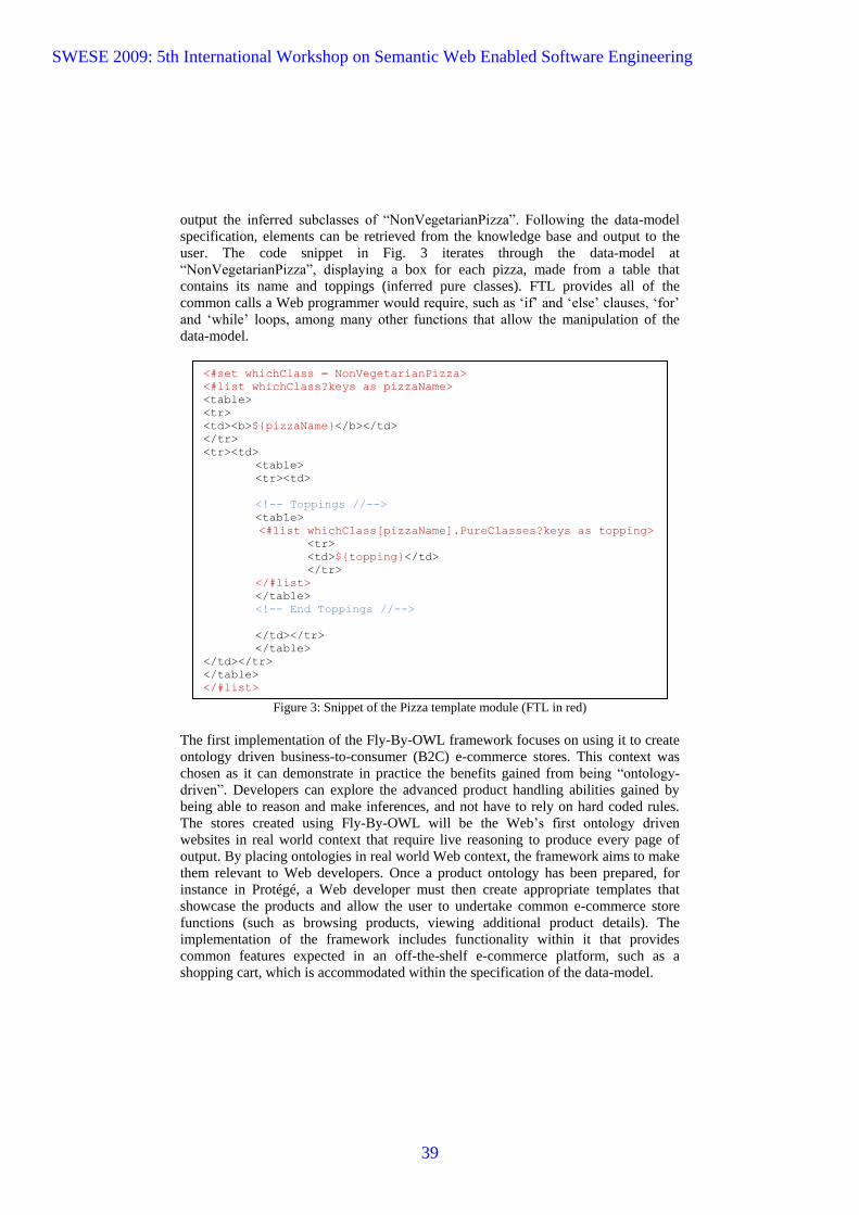
output the inferred subclasses of “NonVegetarianPizza”. Following the data-model
specification, elements can be retrieved from the knowledge base and output to the
user. The code snippet in Fig. 3 iterates through the data-model at
“NonVegetarianPizza”, displaying a box for each pizza, made from a table that
contains its name and toppings (inferred pure classes). FTL provides all of the
common calls a Web programmer would require, such as „if‟ and „else‟ clauses, „for‟
and „while‟ loops, among many other functions that allow the manipulation of the
data-model.
Figure 3: Snippet of the Pizza template module (FTL in red)
The first implementation of the Fly-By-OWL framework focuses on using it to create
ontology driven business-to-consumer (B2C) e-commerce stores. This context was
chosen as it can demonstrate in practice the benefits gained from being “ontology-
driven”. Developers can explore the advanced product handling abilities gained by
being able to reason and make inferences, and not have to rely on hard coded rules.
The stores created using Fly-By-OWL will be the Web‟s first ontology driven
websites in real world context that require live reasoning to produce every page of
output. By placing ontologies in real world Web context, the framework aims to make
them relevant to Web developers. Once a product ontology has been prepared, for
instance in Protégé, a Web developer must then create appropriate templates that
showcase the products and allow the user to undertake common e-commerce store
functions (such as browsing products, viewing additional product details). The
implementation of the framework includes functionality within it that provides
common features expected in an off-the-shelf e-commerce platform, such as a
shopping cart, which is accommodated within the specification of the data-model.
<#set whichClass = NonVegetarianPizza>
<#list whichClass?keys as pizzaName>
<table>
<tr>
<td><b>${pizzaName}</b></td>
</tr>
<tr><td>
<table>
<tr><td>
<!-- Toppings //-->
<table>
<#list whichClass[pizzaName].PureClasses?keys as topping>
<tr>
<td>${topping}</td>
</tr>
</#list>
</table>
<!-- End Toppings //-->
</td></tr>
</table>
</td></tr>
</table>
</#list>
SWESE 2009: 5th International Workshop on Semantic Web Enabled Software Engineering
39

5. Semantic Pizza Store
The example store that has been created to demonstrate the framework and its
capabilities is the “Semantic Pizza Store”, based upon the output of the well known
pizza ontology tutorial, written in Manchester by Matthew Horridge. The tutorial
teaches ontological concepts to new Protégé users [5]. The ontology output from
following the tutorial is used as the knowledge base for the store. The pizzas are
offered for sale, with live inferences being made to categorise pizzas as Vegetarian,
Non-Vegetarian, Spicy, etc and allowing the user to customise standard pizzas and
create their own. The knowledge base can be queried on the fly in “Manchester
Syntax”, for example requesting all pizza‟s from a specific country or of a certain
spiciness. The queries can be either input by the user and POST, or they can be passed
in via an encoded URL in a GET request. The “Semantic Pizza Store” demonstrates
both how ontologies are appropriate as the backend knowledge base to sell the
products in question, pizzas and how they overcome the limitations of a product
database. Fig. 4 shows a screen capture of the home page of the “Semantic Pizza
Store”.
Figure 4: Screen capture of the “Semantic Pizza Store” home page
The popularity of the pizza ontology tutorial makes it appropriate to use in
demonstrating Fly-By-OWL. Its concepts will be familiar to most researchers in the
field. Fig. 4 shows the home page module (“index”) of the “Semantic Pizza Store”.
The pizza subclasses are fetched from the knowledge base and displayed as clickable
boxes, acting as “dynamic categories”, allowing the user to browse pizza‟s of those
types. The results of these classes are inferred. A user can query the knowledge base
SWESE 2009: 5th International Workshop on Semantic Web Enabled Software Engineering
40

in Manchester Syntax, and toppings are displayed so a user can begin to create their
own pizza. Additional functionalities of the “Semantic Pizza Store” include
customising the preset pizzas, creating half and half‟s and adding pizzas to a shopping
cart from where the user can proceed to a checkout, among other functionality
expected in a typical online pizza ordering service. The template modules of the
example store are all written in HTML and make use of CSS and JavaScript, similar
to other current day websites. The data-model is manipulated through FTL scripting,
as was shown in the code snippet in Fig. 3.
The source code of the templates that are used by the “Semantic Pizza Store” is
viewable online at the Fly-By-OWL website. Fig. 5 shows the pizza module,
displaying the subclasses of “NonVegetarianPizza” (results inferred). It is using the
code snippet from Fig. 3 to generate the pizza description boxes. The objective of the
example store is to present the capabilities of the framework to Web developers. The
framework itself can handle any OWL or OWL 2 ontology that is loaded as the
knowledge base. The framework does not treat the pizza ontology different to any
other knowledge base. To create a store using the Fly-By-OWL framework, a Web
developer must upload their ontology and then create appropriate template modules
using the data-model specifications and FTL scripting. This allows a Web developer
to present the concepts within the knowledge base however they best envision.
Figure 5: “Semantic Pizza Store” viewing the NonVegetarianPizza class (results inferred)
Fly-By-OWL allows the creation of “ontology-driven” e-commerce websites while
emphasising its practical relevance to web developers. During development, the pages
output to a user were all generated in under one second. The lengthiest operations
SWESE 2009: 5th International Workshop on Semantic Web Enabled Software Engineering
41

within a page load are reading the ontology itself and the generation of the data
model. While Web application platforms are generally tried-and-tested, the
“ontology-driven” with live reasoning concept is new and further research is required
to understand how it will cope under various loads, and the hardware/ software setup
required to best handle such traffic. Performance monitoring a Fly-By-OWL store
under various traffic loads has been identified as a further research topic. The size of
the ontology being used as the knowledge base and it‟s affect on load times will also
be studied. With further development of the platform‟s architecture, load times are
intended to be comparable to any database-driven Web application.
6. Research agenda
With the first implementation of Fly-By-OWL focused towards an e-commerce
context, research questions arise in regards to how the “ontology-driven” concept will
cope against traditional tried-and-tested back-ends (e.g. a DBMS). A number of
research questions arise in regards to its real-world usage and further development.
How are page load times affected by traffic?
How are page load times affected by size of the knowledge base ontology?
What types of ontology will be used as the knowledge base? E.g.
GoodRelation‟s vocabulary and how will they be handled by Fly-By-OWL?
How should the platform be expanded beyond the e-commerce context and
become more applicable for general Web applications?
What kind of Web services can be created by using XML templates with
FTL scripting and how should they harness reasoning?
7. Conclusion
This paper has presented Fly-By-OWL, a framework that enables the creation of
“ontology-driven” Web applications, with its first implementation aimed specifically
towards e-commerce stores. By following calls for “rapid simplification” of the
Semantic Web, this paper aims to make ontologies relevant to Web developers. By
starting with an analysis of ontology usage within six popular LAMP based Web
applications, it became apparent that the developers of those applications found no
place for ontologies within any standard or road mapped feature. While the Semantic
Web community was active in creating add-on‟s for those applications that allowed
them to make use of ontologies in some form, the scope of their depth was trivial and
they did not play any role vital to the operation of the applications. With Fly-By-
OWL, e-commerce store‟s can be created for the present day Web that are driven by
an ontology. With live reasoning, present day limitations experienced when using a
database can be overcome. The paper demonstrated some features such as using
inferences to dynamically categorise products and customising products without hard
coded rules but verifying consistency. The paper also showcased the “Semantic Pizza
SWESE 2009: 5th International Workshop on Semantic Web Enabled Software Engineering
42
Store”, an example e-commerce store based upon the pizza ontology tutorial created
to demonstrate the framework. A research agenda has been formulated that looks to
address some of the initial questions posed by the “ontology-driven” concept and how
to further Fly-By-OWL‟s overall relevance and scope.
8. Project on the Web
The Fly-By-OWL project website and the “Semantic Pizza Store” are hosted at
Brunel University, U.K. and can be found online at http://www.flybyowl.org. You are
welcome to use the framework to create your own “ontology-driven” e-commerce
stores and interact with our online community.
9. References
[1] P. Warren, The next steps for the web: Putting meaning into the web. Computing & Control
Engineering 1(2), pp. 27-35, 2003.
[2] D. Bradbury, Unweaving the tangled web of dumb data. Computer Weekly 10pp. 1-7, 2003.
[3] T. Berners-Lee, J. Hendler and O. Lassila, "The Semantic Web," Sci. Am., May. 2001.
[4] B. McBride, "Four steps towards the widespread adoption of a semantic web," in ISWC '02:
Proceedings of the First International Semantic Web Conference on the Semantic Web, 2002,
pp. 419-422.
[5] M. Horridge, H. Knublauch, A. Rector, R. Stevens and C. Wroe, "A Practical Guide To
Building OWL Ontologies Using The Protégé-OWL Plug-in and CO-ODE Tools Edition 1.0,"
August. 2004.
[6] Netcraft. (2009, 07/28/2009). July 2009 Web Server Survey. 2009(08/10), Available:
http://news.netcraft.com/archives/2009/07/28/july_2009_web_server_survey.html
[7] T. O'Reilly, "Lessons from open-source software development," Commun ACM, vol. 42, pp.
32-37, 1999.
[8] G. Lawton, "LAMP lights enterprise development efforts," Computer, vol. 38, pp. 18-20,
Sept. 2005.
[9] I. Horrocks, "Semantic web: The story so far," in W4A '07: Proceedings of the 2007
International Cross-Disciplinary Conference on Web Accessibility (W4A), 2007, pp. 120-125.
[10] R. McCool, "Rethinking the Semantic Web, Part 2," IEEE Internet Comput., vol. 10, pp.
96-95, 2006.
SWESE 2009: 5th International Workshop on Semantic Web Enabled Software Engineering
43

[11] J. G. Breslin, S. Decker, A. Harth and U. Bojars, "SIOC: an approach to connect web
based communities," Int.J.Web Based Communities, vol. 2, pp. 133-142, 2006.
[12] M. Hepp, "GoodRelations: An ontology for describing products and services offers on the
web," in EKAW '08: Proceedings of the 16th International Conference on Knowledge
Engineering, 2008, pp. 329-346.
[13] L. Stojanovic, N. Stojanovic and R. Volz, "Migrating data-intensive web sites into the
semantic web," in SAC '02: Proceedings of the 2002 ACM Symposium on Applied Computing,
2002, pp. 1100-1107.
[14] Y. Lei, E. Motta and J. Domingue, "OntoWeaver: An ontology-based approach to the
design of data-intensive web sites," in Hypertext/Hypermedia Handbook, 2005, pp. 244-262.
[15] Y. Jin, S. Decker and G. Wiederhold, "OntoWebber: Model-driven ontology-based web
site management," in Semantic Web Working Symposium (SWWS), 2001.
[16] M. Hepp, D. Bachlechner and K. Siorpaes, "OntoWiki: Community-driven ontology
engineering and ontology usage based on wikis," in WikiSym '06: Proceedings of the 2006
International Symposium on Wikis, 2006, pp. 143-144.
[17] R. McCool, "Rethinking the Semantic Web, Part 1," IEEE Internet Comput., vol. 9, pp. 88-
87, 2005.
[18] M. Horridge, N. Drummond, J. Goodwin, A. L. Rector, R. Stevens and H. Wang, "The
Manchester OWL Syntax," in OWLED; CEUR Workshop Proceedings, 2006.
[19] FreeMarker Project, "FreeMarker: Java Template Engine Library," 2009(08/10),
Available: http://www.freemarker.org
SWESE 2009: 5th International Workshop on Semantic Web Enabled Software Engineering
44
How To Simplify BuildingSemantic Web Applications
Matthias Quasthoff, Harald Sack, Christoph Meinel
Hasso Plattner Institute, University of Potsdam{matthias.quasthoff, harald.sack, meinel}@hpi.uni-potsdam.de
Abstract. This paper formalizes several independent approaches onhow to develop Semantic Web applications using object-oriented pro-gramming languages and Object-Triple Mapping. Using such mapping,Semantic Web applications have been developed up to three times fastercompared to traditional Semantic Web software engineering. Resultsshow that at the same time, developer satisfaction has been significantlyhigher if they used object triple mapping. We present a formal notationof object triple mapping and results of an experimental evaluation clearlyshowing the benefits of such mapping. The work presented here may oneday help to make Semantic Web technologies part of the majority offuture applications.
1 Introduction
Using and handling RDF data in software is not trivial to implement, especiallywith regards to the large number of best practices to consider. Before even that,developers need to learn about RDF concepts and how to deal with them usingRDF programming libraries [1]. For many tasks, additional knowledge aboutRDF schema and OWL is required. This makes getting started with the SemanticWeb quite a challenge for Semantic Web beginners and entry-level developers.
In general, two issues with current Semantic Web programming libraries canbe identified: First, their complete potential is always visible to developers, in-stead of by default only revealing those parts that would be sufficient for a major-ity of implementation problems. Second, lots of RDF- and Linked Data-relatedimplementation tasks, such as discovery, retrieval, and publishing of datasetsneed to be implemented by hand, resulting in huge implementation efforts evenfor relatively small implementation problem (cf. Section 4).
A promising approach for simplifying Semantic Web software developmentis Object Triple Mapping (OTM) [2, 3]. There do exist some OTM implementa-tions, and also some research on its expressivity (cf. Section 2). However, thereis no research on the actual building blocks needed to develop Semantic Webapplications on top of existing RDF programming libraries, and there is no re-search on whether, or how OTM actually simplifies application development.With our work, we are confident to lay out guidelines for the development offuture, easy-to-use Semantic Web programming libraries.
SWESE 2009: 5th International Workshop on Semantic Web Enabled Software Engineering
45

In Section 3, wie formalize OTM and extend it by a small pseudo-code vocab-ulary describing linked data functionality. This formalization is a starting pointfor further research in this important area. We used the formalization for anexperimental evaluation of the benefits of OTM. The results of this evaluationare presented in Section 4. Section 5 concludes the paper.
2 Related work
Linked Data has become one of the most popular topics among the emergingSemantic Web [4]. Best practices need to be identified and described, how to effi-ciently implement linked data applications. Design patterns formalize such bestpractices; not as programming libraries, but as solutions to frequently recur-ring problems. They have been introduced to software engineering by [5]. In theworld of relational database management systems, widely-used design patternson object-relational mapping (ORM) have been identified [6]. These patternsallow developers to simply instantiate objects, and they are automatically filledwith contents from a relational database. Modifications to these objects willautomatically be persisted in the database.
The need of simplifying Semantic Web software engineering in a similar wayto ORM has been identified in [2], and an implementation called So(m)mer,based on meta-programming, is available1. Up to now, several other tools forOTM have been inspired by object-relational mapping. The D2RQ Platform [7]uses a declarative language to describe mappings between relational databaseschemata and Semantic Web ontologies and lets clients access RDF views onthe underlying non-RDF data. Other approaches such as RDFReactor2 takemappings between OO programming units and Semantic Web schemas and allowsoftware developers simplified access to a triple store. OntoJava [8] uses a similarapproach to use auto-generated inference rules inside application source code.Winter [9] extends So(m)mer to allow for mappings of complex patterns insteadof plain RDF classes onto Java classes.
All these solutions and the research done around them focus on specific partsof the approach chosen, such as feasibility and expressivity of such mapping, butdo not yet aim at supporting the whole process of discovering, retrieving, pro-cessing, and re-publishing linked data, which will involve further steps such as,e.g., policy or data license checking [10]. To overcome this situation we have iden-tified the principles common to these solutions and formulated design patternsfor OTM, closely resembling ORM design patterns [3]. As our contribution inthis paper, we will formalize the design pattern and evaluate how actual softwarecan be built upon it.
1 https://sommer.dev.java.net/2 http://semanticweb.org/wiki/RDFReactor
SWESE 2009: 5th International Workshop on Semantic Web Enabled Software Engineering
46

3 Formalizing OTM
It is good practice to encapsulate business or domain logic in classes and methodsof object-oriented (OO) programming languages [6]. E.g., if a software productdeals with people and relations between them, the software’s object model likelycontains a Person class and friends field for this class. To use RDF data in mostOO programming languages, the mapping from RDF properties to the domainclasses’ fields has to be implemented by hand. Our hypothesis is that large partsof this OO handling of RDF concepts, including discovery and retrieval on theWWW, should be hidden from software engineers, making the development ofSemantic Web software much easier, and hence encouraging software developersto actually start creating such software. In the following sections, we introduce aformal notation of the knowledge representation in OO programming, a mappingbetween RDF and OO concepts, and a simple pseudo-code vocabulary relevantfor building applications using such mapping.
3.1 Basic concepts
The RDF data model has an established formal notation building upon thefollowing concepts [1].
Definition 1 (RDF data model) Let U be the set of URI references, B aninfinite set of blank nodes, and L the set of literals.
– V := U ∪B ∪ L is the set of RDF nodes,– R := (U ∪ B) × U × V is the set of all triples or statements, that is, arcs
connecting two nodes being labelled with a URI,– any G ⊆ R is an RDF graph.
How RDF graphs are actually constructed, handled, and transferred is subjectto standards, conventions, and technical constraints. Linked data principles [4]suggest to provide smaller sub-graphs describing individual resources. In [11],an abstraction on top of these principles is described providing the whole Webof Data as one huge graph. Hence, operating on RDF data involves not onlyoperating on triples and resources, but also retrieving the right sub-graphs of R,which will be described in a later section.
For OO programming, there is no single established formal notation focusingon the information representation part. Hence, we just use some basic formalconcepts to capture OO environments form the information representation per-spective.
Definition 2 (OO data model) Let O be a set of object identifiers, F a setof field names.
– S := P(O)F is the set of field assignments s : F → P(O),– Q := SO the set of system states q : O → S.
SWESE 2009: 5th International Workshop on Semantic Web Enabled Software Engineering
47
A system state q ∈ Q maps each object o ∈ O onto a field assignment s :=q(o) ∈ S, which in turn maps each field name f ∈ F onto the object’s valuess(f) ⊆ O for this field. Note that in our notation, a field assignment returnssets of objects as field values. This allows to represent programming conceptssuch as array or collection objects. Ordered lists and formal cardinality and typerestrictions (i.e., scalar-value fields or statically typed object definitions) on OOdata models are outside the scope of this paper but can easily represented ontop of our formalism if needed.
Example 1 (comparison of RDF and OO data model) Let p1, p2, p3 ∈ Ube URI denoting three people, n ∈ U be the URI foaf:name and k ∈ U be theURI foaf:knows. An RDF graph describing p1 and p2 might look the following.
G :={〈p1, n, “John Doe”〉, 〈p1, k, p2〉, 〈p1, k, p3〉, 〈p2, n, “Jane Doe”〉
}Let us now have a look at this example from the OO perspective. Let o1, o2, o3 ∈O be object identifiers denoting three people, name, friends ∈ F be field names,q ∈ Q a system state, and s1 := q(o1), s2 := q(o2). The OO representation of Gwill look the following.
s1(name) = {“John Doe”}s2(name) = {“Jane Doe”}
s1(friends) = {o2, o3}
3.2 Mapping RDF and OO
In this sections we continue to use the set definitions from the previous section.
Definition 3 (Object triple mapping, OTM) An object triple mapping foran RDF Graph R, fields F and objects O is some (G, mt, ma, q) such that
– G ⊆ R is an RDF graph– mt : F ′ → U for mapped fields F ′ ⊆ F (the vocabulary map),– ma : O′ → U for mapped objects O′ ⊆ O (the instance map)– q ∈ Q a system state such that for all u ∈ U , o ∈ O′, f ∈ F ′ and s := q(o)• |m−1
a (u) ∩ s(f)| ≤ 1• |m−1
a (u) ∩ s(f)| = 1⇔ 〈ma(o), mt(f), u〉 ∈ R
Note that this definition does not require the instance map ma to be injective,which would be desirable in many cases, at least from a software engineer’spoint of view. However, there might be different simultaneous OO representa-tions oi of a single RDF resource u resulting from, e.g., different data licenses,trust policies, or access control decisions. Hence, the injectivity of the actualinstance map presented to the developer should rather be ensured using addi-tional formal representations of policies, contexts and the like, instead of beinga general requirement to the instance map. Also, our notion of OTM does not
SWESE 2009: 5th International Workshop on Semantic Web Enabled Software Engineering
48
necessarily require a class map for RDF and OO, since many dynamically-typedobject-oriented programming languages do not have the notion of classes. Forstatically-typed programming languages, an implementation of such class mapwill however be required. Treating other RDF concepts such as lists or reifica-tion, and also the semantics of RDFS and OWL are not part of this mapping,but subject to OTM implementations.
Example 2 (OTM) To map RDF representations of people to the correspond-ing OO representation (cf. example 1), we need
– a vocabulary map mt : name 7→ n, friends 7→ k;– mapped objects o′1, o
′2, o′3 ∈ O′ such that ma : o′1 7→ p1, o′2 7→ p2, o′3 7→ p3;
– a system state q ∈ Q and field assignments s′1 := q(o′1) and s′2 := q(o′2).
The mapped objects o′1, o′2 will exactly look like o1, o2 from example 1:
– s′1(name) = {“John Doe”} because 〈ma(o′1)︸ ︷︷ ︸=p1
, mt(name)︸ ︷︷ ︸=n
“John Doe”〉 ∈ G
– s′2(name) = {“Jane Doe”} because 〈ma(o′2)︸ ︷︷ ︸=p2
, mt(name)︸ ︷︷ ︸=n
“Jane Doe”〉 ∈ G
– s′1(friends) = {o′2, o′3}, because 〈ma(o′1)︸ ︷︷ ︸=p1
, mt(friends)︸ ︷︷ ︸=k
,ma(o′i)︸ ︷︷ ︸=pi
〉 ∈ G.
Although several implementations of such mapping exist (cf. Section 2), for ourresearch we use our own OTM implementation, which is available licensed underthe GPL3. This implementation strictly follows the OTM design patterns derivedfrom object-relational patterns [3, 6].
3.3 Building Linked Data software
Building a linked data application using OO programming will involve handlingRDF resources as OO objects. There are only two ways to obtain objects fromresources, and we introduce the following pseudo-code notation for them:
– get(u) for u ∈ U : Request o ∈ O′ such that ma(o) = u;– query(pattern): Request O′′ ⊆ O′ matching a pattern, using SPARQL.
From Definition 3, it is not clear how the RDF graph G is obtained. G will beconstructed during application execution using the follwoing ways.
– Directly query a triple store, e. g., using SPARQL,– load(u) for u ∈ U : Ensure that the dereferenced graph Gu ⊆ G,
Following linked data principles, an OTM implementation can automatically callload(u) on occurences of get(u). Just as this simplifies resource handling, twomore pseudo-code operations are required to build linked data applications.
3 http://projects.quasthoffs.de/otm-j
SWESE 2009: 5th International Workshop on Semantic Web Enabled Software Engineering
49

– use(u) for u ∈ U : Set up the OTM implementation to use the dataset u,i. e. evaluate the data license, and set up the SPARQL endpoint to be used.Even further decisions can be made, such as deciding upon some statisticswhether to dereference single URIs for this dataset or rather to download adata dump.
– publish(O′′) for O′′ ⊆ O: Publish objects as linked data, either by pro-ducing serialized RDF files, or by hooking into some Web programmingframework. By configuring meta-data for publication such as licenses, sev-eral checks, e. g. on license compatiblity, can be performed.
4 Evaluation
Our primary motivation for investigating OTM is to understand why SemanticWeb technologies have been picked up so hesistatingly by software developers,and to show software developers how they can simply use and benefit fromthese technologies. We asked software engineers with little or no experience inSemantic Web software engineering (but yet sufficient programming skills) tosolve a problem using RDF data sources and programming libraries.
4.1 Setup
Each participant was assigned two tasks, one of which was to be solved withoutOTM, and the other one using OTM. The order of the two tasks and the order ofusing/not using OTM was randomized to ensure the results will not be distortedby learning effects. Participants used the Eclipse programming environment andthe jUnit framework to test their results4. To simulate the usual work-flow ofWeb programmers, we provided the participants with example source code ofsimilar solutions [12].
Tasks. The experiment dataset consisted of 12,726 fictious foaf:Person re-sources, 100 foaf:Document resources, 15 foaf:Group resources, and 169 bldg:Roomresources5. Each document had between 2 and 4 authors, each group between 8and 15 members, and each person knew a number of other people. All resourcescould be dereferenced by their URI. The following tasks needed to be solved.
Task 1. Given a set of URI identifying documents, construct the set of all thedocuments’ authors’ names.
Task 2. Given a URI identifying a person, construct the set of all person’sfriends’ friends’ names.
The participants were expected to find a solution close to the following pseudo-code (using the vocabulary from Section 3.3), which was however not presentedto the participants.4 http://eclipse.org/, http://junit.org/5 foaf: http://xmlns.com/foaf/0.1/, bldg: http://example.org/buildings/
SWESE 2009: 5th International Workshop on Semantic Web Enabled Software Engineering
50

Solution 1. GET_AUTHOR_NAMES(publication_uris):load(dataset_uri)for each uri in publication_uris
publication = get(uri)for each person in publication.authors
return person.nameSolution 2. GET_SECOND_ORDER_FRIENDS(person_uri):
load(person_uri)person = get(person_uri)for each friend in person.friends
load(friend.uri)for each friend2 in friend.friends
load(friend2.uri)return friend2.name
4.2 Metrics
Difficulty. After each of the two assignments, participants were asked to esti-mate the difficulty of the assigment, the maintainability of the resulting sourcecode, and how difficult a solution would have been using XML stores or RDBMSinstead of RDF, on a scale from 0 (trivial) to 10 (too hard). After the first as-signment only (which randomly had to be solved either using OTM or withoutOTM), participants were asked whether they see potential use of RDF in theirnear-future projects. Along with these subjective measures, we tracked the timerequired to find a working solution, and the number of edit-debug cycles.
Source code. Since OTM encapsulates large parts of RDF data handling itis expected that solutions building on OTM will have less lines of code thansolutions than non-OTM solutions. To get a deeper understanding of how linesof code will be reduced, we separately counted lines of code carrying
– language constructs such as loops, variable declarations etc.;– RDF library initialization code, i. e. creation of or connection to data stores;– data access code, i. e. imperative statements for URI handling such as get,
load, use, or query operations, (cf. Section 3.3), and RDF concept manip-ulation using RDF libraries; and
– business or domain logic, i. e. lines of code manipulating domain objectssuch as people, publications or names, e. g., by handling or accessing fieldsof domain objects.
Feedback. Besides these rather quantitative metrics, we gathered feedback dur-ing and after the experiment. In a questionnaire, we asked the participants toidentify the biggest problems during finding the solutions, and to name othertypes of support they wished they had.
SWESE 2009: 5th International Workshop on Semantic Web Enabled Software Engineering
51

4.3 Participants
Undergraduate computer science students at Hasso Plattner Institute, Universityof Potsdam were invited to to participate in the experiment. Ten participantsaged 19 to 27 (mean 22.6) actually took part in the experiment. All participantshad between 4 and 9 years of programming experience (mean 6.6). Accordingto their estimation on a scale from 0 (none) to 10 (expert) prior to solving theassignments, only three of them said having some basic knowledge about RDF,the others none (mean 0.9). All participants were experienced with the Javaprogramming language (mean 5.4). Also, most participants had some experienceusing traditional information stores such as XML documents (mean 3.4) andRDBMS (mean 3.9).
4.4 Results
Difficulty. The results for developer satisfaction were surprisingly clear (Fig. 1).Implementing the assignments was found to be significantly easier using OTM(mean 2.4, σ = 1.8) than using the Jena RDF library only (mean 6.4, σ = 2.1).Also, the participants judged their solution significantly easier to maintain (bothfor themselves: 1.13, σ = 1.6, and if they let somebody else do it: 2.13, σ = 1.5),if OTM had been used compared to non-OTM (means 4.3, σ = 1.8 and 5.9,σ = 1.1). However, whether the first assignment was to be solved using OTM orwithout OTM had no influence on the participants’ estimation of the difficulty ofintegrating Semantic Web technologies in their own future projects (means 4 and5). Regarding the estimated difficulties, we can eliminate variance by comparingthe differences of the difficulty of the implementation and the estimated difficul-ties of alternative approaches using XML or RDBMS (Fig. 2). By means, thenon-OTM solution has been rated more difficult compared to traditional dataformats, whereas the OTM solution has been rated easier to implement thantraditional data formats. However, the differences for these relative difficultiesare not significant. For Task 1 (finding the names of publication authors), boththe number of edit cycles (non-OTM mean 29, σ = 6.6) and the time needed tofind the solution (mean 1.2 hours, σ = 0.5) was significantly lower using OTM(8.8 edit-debug cycles, σ = 6.2 and 0.4 hours, σ = 0.2, Fig. 3). For Task 2(finding the names of friends’ friends), the mean number of edit-debug cycleswas increased from 8 to 19, while the mean time needed to find the solution wasdecreased from 0.6 hours (σ = 0.3) to 0.4 hours (σ = 0.4) using OTM. However,the differences for Task 2 are not significant. The combined figures for Task 1and Task 2 show that the number of edit-debug cycles remains stable, but thedevelopment time has been decreased significantly using OTM. It is unclear whythe number of edit-debug cycles is larger for Task 2 using OTM. But since thedevelopment time was not increased, we do not consider this a general weaknessof OTM. It will however be interesting to direct further research in this direction.
Source code. The figures for the source code metrics are clear again (Fig.4). The overall lines of code are reduced from 20.9 (σ = 5.4) not using OTM
SWESE 2009: 5th International Workshop on Semantic Web Enabled Software Engineering
52
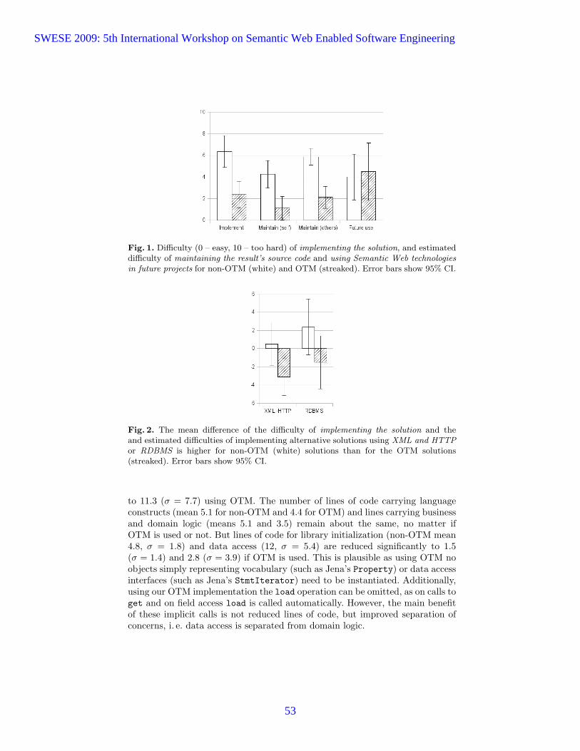
Fig. 1. Difficulty (0 – easy, 10 – too hard) of implementing the solution, and estimateddifficulty of maintaining the result’s source code and using Semantic Web technologiesin future projects for non-OTM (white) and OTM (streaked). Error bars show 95% CI.
Fig. 2. The mean difference of the difficulty of implementing the solution and theand estimated difficulties of implementing alternative solutions using XML and HTTPor RDBMS is higher for non-OTM (white) solutions than for the OTM solutions(streaked). Error bars show 95% CI.
to 11.3 (σ = 7.7) using OTM. The number of lines of code carrying languageconstructs (mean 5.1 for non-OTM and 4.4 for OTM) and lines carrying businessand domain logic (means 5.1 and 3.5) remain about the same, no matter ifOTM is used or not. But lines of code for library initialization (non-OTM mean4.8, σ = 1.8) and data access (12, σ = 5.4) are reduced significantly to 1.5(σ = 1.4) and 2.8 (σ = 3.9) if OTM is used. This is plausible as using OTM noobjects simply representing vocabulary (such as Jena’s Property) or data accessinterfaces (such as Jena’s StmtIterator) need to be instantiated. Additionally,using our OTM implementation the load operation can be omitted, as on calls toget and on field access load is called automatically. However, the main benefitof these implicit calls is not reduced lines of code, but improved separation ofconcerns, i. e. data access is separated from domain logic.
SWESE 2009: 5th International Workshop on Semantic Web Enabled Software Engineering
53

(a) number of edit-debug cycles (b) time in hours needed to find solu-tion
Fig. 3. Depending on the implementation task, the number of edit-debug cycles can bereduced significantly using OTM (streaked), compared to OTM (white), 3(a). OTMcan also significantly reduce the implementation time of Task 1. In spite of increasednumber of edit-debug cycles for Task 2, the time needed to find the solution is notincreased, 3(b). Error bars show 95% CI.
Fig. 4. The significant decrease in lines of code using OTM is achieved by reducinglibrary initialization and data access code. Error bars show 95% CI.
SWESE 2009: 5th International Workshop on Semantic Web Enabled Software Engineering
54
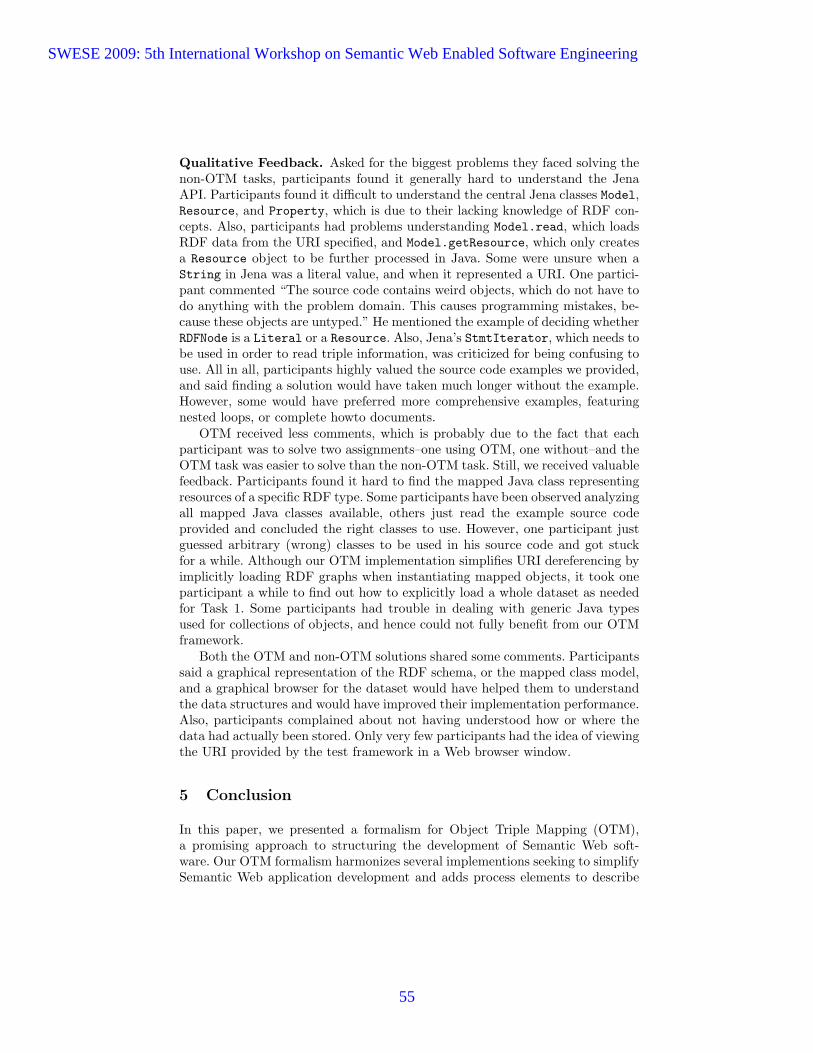
Qualitative Feedback. Asked for the biggest problems they faced solving thenon-OTM tasks, participants found it generally hard to understand the JenaAPI. Participants found it difficult to understand the central Jena classes Model,Resource, and Property, which is due to their lacking knowledge of RDF con-cepts. Also, participants had problems understanding Model.read, which loadsRDF data from the URI specified, and Model.getResource, which only createsa Resource object to be further processed in Java. Some were unsure when aString in Jena was a literal value, and when it represented a URI. One partici-pant commented “The source code contains weird objects, which do not have todo anything with the problem domain. This causes programming mistakes, be-cause these objects are untyped.” He mentioned the example of deciding whetherRDFNode is a Literal or a Resource. Also, Jena’s StmtIterator, which needs tobe used in order to read triple information, was criticized for being confusing touse. All in all, participants highly valued the source code examples we provided,and said finding a solution would have taken much longer without the example.However, some would have preferred more comprehensive examples, featuringnested loops, or complete howto documents.
OTM received less comments, which is probably due to the fact that eachparticipant was to solve two assignments–one using OTM, one without–and theOTM task was easier to solve than the non-OTM task. Still, we received valuablefeedback. Participants found it hard to find the mapped Java class representingresources of a specific RDF type. Some participants have been observed analyzingall mapped Java classes available, others just read the example source codeprovided and concluded the right classes to use. However, one participant justguessed arbitrary (wrong) classes to be used in his source code and got stuckfor a while. Although our OTM implementation simplifies URI dereferencing byimplicitly loading RDF graphs when instantiating mapped objects, it took oneparticipant a while to find out how to explicitly load a whole dataset as neededfor Task 1. Some participants had trouble in dealing with generic Java typesused for collections of objects, and hence could not fully benefit from our OTMframework.
Both the OTM and non-OTM solutions shared some comments. Participantssaid a graphical representation of the RDF schema, or the mapped class model,and a graphical browser for the dataset would have helped them to understandthe data structures and would have improved their implementation performance.Also, participants complained about not having understood how or where thedata had actually been stored. Only very few participants had the idea of viewingthe URI provided by the test framework in a Web browser window.
5 Conclusion
In this paper, we presented a formalism for Object Triple Mapping (OTM),a promising approach to structuring the development of Semantic Web soft-ware. Our OTM formalism harmonizes several implementions seeking to simplifySemantic Web application development and adds process elements to describe
SWESE 2009: 5th International Workshop on Semantic Web Enabled Software Engineering
55

complete programs operating on linked data. Our second contribution is an ex-perimental evaluation of OTM. We presented the results of this experiment,clearly showing that
– OTM speeds up the development of Semantic Web software.– Lines of code needed to solve several tasks are reduced by half using OTM,
and the share of “purely technical” lines of code is diminished so that usingOTM, business logic and program structure stands out in the code.
– Improved programming experience can be measured, as developers withoutSemantic Web programming experience find it simpler to develop softwareusing OTM, and are more satisfied with the quality of their results.
The experiment material, assignments, datasets etc. can be downloaded fromthe experiment web site6. We encourage readers to join the evaluation, and sharetheir results with us. To obtain a broader view on what are the Semantic Websoftware engineers’ pains, how we can help them, and which technology theyactually prefer, we will extend our evaluation to more programming languagesand RDF programming libraries. Besides this planned continuous evaluation, wewill publish the direct and indirect feedback we receive from participants, andwill incorporate that feedback into our own OTM implementation for furtherevaluation, and are willing to contribute to other existing OTM implementations.
As the results of our experiment are very promising, we are confident tocontribute in further spreading the word about positive experience using Se-mantic Web standards and technologies. Once software engineers and managersare convinced that Semantic Web technologies can be introduced in softwareprojects without adding costs, or even reducing costs, software will start to con-tain more and more Semantic Web technologies, fostering interoperability anddata mash-ups. By then, software engineers will be willing to learn more aboutthese technologies and more complex software projects going beyond the featuresof off-the-shelf OTM implementations can finally be done.7
References
1. Manola, F., Miller, E.: Rdf primer. w3c recommendation 10 february 2004.http://www.w3.org/TR/2004/REC-rdf-primer-20040210/ (2004)
2. Story, H.: Java annotations and the semantic web.http://blogs.sun.com/bblfish/entry/java annotations the semantic web (2005)
3. Quasthoff, M., Meinel, C.: Design patterns for the web of data. In: Proc. of IEEESCC 2009. (2009)
4. Berners-Lee, T.: Linked data. http://www.w3.org/DesignIssues/LinkedData.html(2006)
5. Gamma, E., Helm, R., Johnson, R., Vlissides, J.: Design Patterns. Elements ofReusable Object-Oriented Software. Addison-Wesley (1994)
6 http://hpi-web.de/meinel/quasthoff/otm-experiment-2009-067 For the cited work still to appear ([13] and [3]), please find the electronic version at
http://hpi-web.de/meinel/quasthoff.
SWESE 2009: 5th International Workshop on Semantic Web Enabled Software Engineering
56
6. Fowler, M., Rice, D.: Patterns of Enterprise Application Architecture. Addison-Wesley (2003)
7. Bizer, C., Seaborne, A.: D2rq – treating non-rdf databases as virtual rdf graphs.In: Proc. of the 3rd International Semantic Web Conference, Springer (2004)
8. Eberhart, A.: Automatic generation of java/sql based inference engines from rdfschema and ruleml. In: Proc. of the 2nd International Semantic Web Conference,Springer (2002)
9. Saathoff, C., Scheglmann, S., Schenk, S.: Winter: Mapping rdf to pojos revisited.In: Proccedings of the ESWC 2009 Demo and Poster Session. (2009)
10. Miller, P., Styles, R., Heath, T.: Open data commons, a licence for open data. In:Proceedings of the WWW2008 Workshop on Linked Data on the Web, Springer(2008)
11. Hartig, O., Bizer, C., Freytag, J.C.: Executing sparql queries over the web of linkeddata. In: Proc. of the 8th International Semantic Web Conference, Springer (2009)
12. Brandt, J., Guo, P.J., Lewenstein, J., Klemmer, S.R.: Opportunistic programming:How rapid ideation and prototyping occur in practice. In: Proc. of the FourthWorkshop on End-User Software Engineering, ACM (2008)
13. Quasthoff, M., Sack, H., Meinel, C.: Can software developers use linked datavocabulary? In: Proc. of I-Semantics ’09. (2009)
SWESE 2009: 5th International Workshop on Semantic Web Enabled Software Engineering
57
Ontology-Driven Software: What We Learned FromUsing Ontologies As Infrastructure For Software
Or How Does It Taste to Eat Our Own Dogfood
Csongor Nyulas, Natalya F. Noy, Michael Dorf, Nicholas Griffith,Mark A. Musen
Stanford University, Stanford, CA 94305, US{nyulas,noy,mdorf,ngriff,musen}@stanford.edu
Abstract. In recent years, researchers have argued that using ontologies to repre-sent and drive knowledge infrastructure of software projects provides separationof the declarative and procedural knowledge and enables easier evolution of thedeclarative knowledge. We have validated these conjectures in the context of Bio-Portal, a repository of biomedical ontologies, which was developed in our group.We are using the BioPortal Metadata Ontology to represent details about all theontologies in the repository, including internal system information and the infor-mation that we collect from the community such as mappings between classes indifferent ontologies, ontology reviews, and so on. To the best of our knowledge,BioPortal is the first large-scale application that uses ontologies to represent es-sentially all of its internal infrastructure.The BioPortal Metadata Ontology extends several other ontologies for repre-senting metadata, such as the Ontology Metadata Vocabulary and the ProtegeChanges and Annotations Ontology. In this paper, we show that it is feasibleto describe the structure of the data that drives an application using ontologiesrather than database schemas, which are used traditionally to store the infrastruc-ture data. We also show that such approach provides critical advantages in termsof flexibility and adaptability of the tool itself. We demonstrate the extensibil-ity of the approach by enabling representation of views on ontologies and theircorresponding metadata in the same framework.
1 Representing Knowledge Infrastructure: From DatabaseSchemas to Ontologies
The topic of using Semantic Web technology to facilitate software development, inte-gration, and evolution has been an active area of Semantic Web research, with annualworkshops on Semantic-Web Enabled Software Engineering (SWESE). Researchershave pursued several different directions in this line of work: generating software codefrom ontologies [7] or using ontologies to describe inputs, outputs, or tasks of soft-ware components to enable integration of software and services [12]; facilitating gath-ering of requirements from domain experts [1]; using ontology-based reasoning to val-idate integrity and consistency of software models [2]; or facilitating critical software-engineering tasks, such as configuration management [16] and product management [8].These novel applications, as well as the traditional ones, use ontologies to describeonly some of the artifacts, whereas the structure of the rest of the data is reflected in a
SWESE 2009: 5th International Workshop on Semantic Web Enabled Software Engineering
58
database schema. In this paper, we describe an approach to application development thatpushes this envelope to use ontologies and ontology instances to represent essentiallyall data that the application requires in a single flexible framework, from declarativehigh-level descriptions of the data as in the examples above to internal system data.
For large-scale distributed architectures today, the development stack includes sev-eral technologies wrapped around a SQL database schema, such as persistence man-agers (e.g., Hibernate), a web server, and so on. When the database schema changes,these changes often need to be propagated through the development stack, thus makingsuch changes expensive in distributed web-based applications. We have encounteredthis problem in developing BioPortal1—a community-based repository of biomedicalontologies, containing 170 ontologies with more than one million classes among themat the time of this writing. Users can submit their ontologies to BioPortal; search acrossall ontologies; browse the ontologies, their different versions, and the associated de-scriptions and provenance information; describe their ontology-related projects and linkthe descriptions to the ontologies; leave comments on classes and on ontologies; createmappings between concepts in one ontology and concepts in another ontology [11].
The BioPortal application is heavily knowledge-driven: most of what the users seewhen browsing BioPortal (in addition to the ontologies themselves), is some renderingof information that would traditionally be in a database. This internal information thatdrives the application includes the metadata about ontologies in the repository, such asontology domain, authors, and other provenance information, as well as information onwhich property to use for preferred name and synonyms in each ontology, informationon where the ontology itself resides in the system (e.g., the specific database table),when it was uploaded, the name of the administrator of the ontology in BioPortal, andso on. Some of this information (such as provenance) is intrinsic to the ontology artifactand is relevant outside of BioPortal; some information is internal system information.
Because the BioPortal application is novel in many of its aspects, our internal in-frastructure continues to evolve constantly, as we understand better user requirements,learn what works and what does not, get new collaborators that would like to extendBioPortal in a certain way. With the knowledge infrastructure constantly in flux, wefound that describing and representing the structure of the knowledge as a relationaldatabase schema did not provide the flexibility and quick adaptability that our usersrequired. Making changes was cumbersome and put a bottleneck in the development ofthe software code. It also made it much harder for anyone to adapt the BioPortal codefor their own purposes as the developers had to be familiar with the entire developmentstack (including Protege, Java, Spring, Hibernate, and Ruby-on-Rails).
Thus, we decided to “eat our own dog food:” we developed an ontology to describethis infrastructure and represented the application data itself as ontology instances. Thusthe whole BioPortal application is driven by ontologies and ontology instances. Notethat while BioPortal is a repository of ontologies, the infrastructure that we describe isnot specific to the artifacts represented in a repository. It will work for a repository ofany other artifacts, not necessarily ontologies. To the best of our knowledge, BioPortalis the first large-scale application of this approach.
This paper makes the following contributions:
1 http://bioportal.bioontology.org
SWESE 2009: 5th International Workshop on Semantic Web Enabled Software Engineering
59

– We developed an ontology to represent the infrastructure and run-time data of alarge community-based ontology repository.
– We implemented the infrastructure of BioPortal using an ontology to represent mostof the data required to drive the application.2
– We validated the extensibility of the approach by adding functionality to supportflexibly representation of ontology views.
2 Types of Metadata in the Repository
The BioPortal ontology repository is an active ontology repository with a large usercommunity that contributes its content and uses its web services in their applications.In addition to more than 170 ontologies, it currently contains multiple versions of theseontologies, submitted by their authors and almost one million mappings between con-cepts in the ontologies. There are descriptions of ontology-based projects, and notesand discussions on classes and ontologies. The BioPortal Resource index providesontology-based access to several biomedical data sets available online (e.g. entries inGEO, ClinicalTrials.gov). All BioPortal functionality is supported by a rich metadatainfrastructure, which includes the following types of metadata:
– ontology metadata describing the ontologies and their provenance and includesontology name, domain, description and keywords, authors, license information,versions, references, and metrics such as the number of classes and properties;
– mappings between concepts, and metadata associated with mappings, such as howthe mapping was created, whether it was created manually or computed automati-cally by a particular algorithm (and which one) and context for the mapping [10];
– ontology reviews are contributed by users as part of their evaluation of ontologiesin BioPortal;
– notes on classes are user-contributed notes that can contain questions, comments,and suggestions, usually addressed to the authors of specific ontology classes;
– projects that use ontologies, described by BioPortal users;– user information such as user profiles, information on who administers each on-
tology and each project description, who contributed notes, mappings, and reviewsto BioPortal, and so on.
3 Functional and Architectural Requirements for MetadataSupport
The BioPortal application dictates the following functional and architectural require-ments for the metadata support:
Efficient and scalable support of BioPortal main functions: Any metadata infrastruc-ture must support fast access to metadata, flexible querying of specific metadata itemsand their combination, and be scalable. We envision that the number of users, notes,projects, and mappings will grow significantly in the coming months.
2 At the time of this writing, some data, such as mappings and user information, is still indatabase tables from our initial implementation of BioPortal.
SWESE 2009: 5th International Workshop on Semantic Web Enabled Software Engineering
60

Support for ontology versioning: Users can upload successive versions of their ontolo-gies and explore any ontology version. There must be services that always resolve to thelatest version of an ontology, with each ontology having a “virtual” location that alwaysredirects to the latest version. Metadata referring to an ontology or its components (e.g.,reviews, notes, mappings) must be attached to a specific version of an ontology.
Flexible evolution of the metadata schema: One of the key requirements for metadatasupport is its ability to adapt easily to new requirements and types of metadata. Thetypes of metadata that an ontology repository requires is still an active area of research.Thus, the structure of the metadata and the specific properties change frequently. Thesechanges to the schema describing the metadata must be easy to implement and roll out.
Customizability of the metadata schema: Some groups install their own versions ofBioPortal software to support either a broader scope than just biomedicine (e.g., theOpen Ontology Repository sandbox3) or to maintain a repository open only to a spe-cific set of users (e.g., the Marine Metadata Initiative4). Developers that maintain theseBioPortal installations usually customize the code to satisfy the local requirements. Forexample, the fields that describe an ontology and its provenance are different for differ-ent communities. Definitions of mappings and the associated metadata differ as well.The representation of metadata schema must make it easy for these developers to cus-tom tailor what gets represented and what gets presented in the user interface.
Reuse of existing technologies and ontologies: Wherever possible, we would like to useexisting technologies and standards for representing metadata. For example, the Ontol-ogy Metadata Vocabulary (OMV) [14] provides a vocabulary for describing ontologies.There are several ontologies and APIs for describing mappings (e.g., the alignmentAPI [4] or the Protege mapping ontology [10]). Reusing these ontologies enables usnot only to use technologies that have already been tested but also to share the datarepresented using these ontologies. For example, by using OMV to represent ontologymetadata, we can share these descriptions with other repositories that use OMV, suchas Oyster [13] and Cupboard [3]. Similarly, the comments on ontologies that BioPortalusers provide are useful for ontology authors when they evolve their ontology. In or-der for ontology authors to see these comments alongside the ontology classes in theirfavorite ontology-editing environment (such as Protege). Thus, the comments must berepresented in the format that an ontology editor, such as Protege, can understand (e.g.,the Protege Changes and Annotations Ontology, CHAO [9]).
In our initial implementation of BioPortal we used a database schema to describeour metadata, with column names corresponding to metadata fields. This approach isfairly traditional for many large-scale implementations and supports the first two re-quirements in our list—efficient and scalable handling of metadata and support for on-tology versioning. However, in our experience, this approach did not fare so well onother requirements.
Any time we needed to add a new metadata field, we had to change not only thedatabase schema, but also the rest of the application stack (e.g., Hibernate) to reflect the
3 http://oor-01.cim3.net/home/release4 http://mmisw.org/or/
SWESE 2009: 5th International Workshop on Semantic Web Enabled Software Engineering
61

change. These changes were time-consuming and cumbersome. Yet, the more we weredeveloping BioPortal, the more features we were adding, the more often we needed toadjust the metadata representation. For instance, in addition to describing the ontolo-gies themselves, we needed to add ontology views, to support ontology reviews alongseveral different dimensions, and to represent a large set of ontology metrics—all ofthese requirements crystalized after the start of the development.
With the metadata schema encoded as a database schema, any customization of newBioPortal installation requires changes to the schema as well. And, as we mentionedearlier, this process is cumbersome and error-prone.
Reusing and sharing the metadata that we collect also was not straightforward: itis hard to find two applications that use the same database schema. Thus, in order totransform the metadata from our internal representation to the representation that an-other repository (e.g., Oyster) uses or to represent comments in a format that a tool suchas Protege would understand, we must write a script to export the data.
While none of these challenges are insurmountable, we decided to apply a com-pletely different approach to representing metadata infrastructure in BioPortal to ad-dress these requirements. As we show in the remaining sections, this approach satisfiedour requirements and proved to be extensible enough to support new requirements.
4 Architecture
Figure 1 shows the architecture of BioPortal. It is a traditional service-oriented lay-ered architecture, with the front end (Ruby-on-Rails) accessing the backend informa-tion through RESTful services.5 There are services to access ontology information (e.g.,get information about a specific ontology, upload a new version, get a diff between twoversions), concept-level services (e.g., get class definition), hierarchy services (e.g., getall subclasses of a class), search services (e.g., search for a term across all ontologies),and other services. The business logic tier implements these services in Java, using theSpring framework. This layer is the one that contains the logic to translate the internalmetadata representation into responses to service request (e.g., a service may request alist of all versions for a specific ontology). Before we transitioned to the ontology-basedapproach, the database schema of the underlying relational database (mySQL) was re-flected directly in the implementation of this layer and its metadata functions. In ourcurrent approach, the metadata structure is accessed through the Protege ontology API.This API, in turn, does use a database to store the ontology and the instances. However,the schema of the database that the Protege uses does not depend on the ontology itself.It is a single table that stores both the ontology and the instance information.6
The types of metadata and their properties are describe in the BioPortal MetadataOntology.7 The metadata values are Protege instances and property values (see Figure 2for an example). We use the Protege API to access the ontology and instances.
5 http://bioontology.org/wiki/index.php/BioPortal_REST_services6 http://protege.cim3.net/cgi-bin/wiki.pl?JdbcDatabaseBackend7 http://bioportal.bioontology.org/virtual/1148
SWESE 2009: 5th International Workshop on Semantic Web Enabled Software Engineering
62

NCBO BioPortal
JSF
.NET
PHP
FLEX
Jboss J2EE Server
Web Container
Ruby on Rails
RESTful Services (HTTP)
Acegi Security Framework
Spring Framework Protégé
MySQL RDBMS
Hibernate ORM
PresentationTier
ServiceTier
BusinessLogicTier
PersistenceTier
Representing metadata
infrastructure
BEFORE
AFTER
Fig. 1. Layered architecture of BioPortal: The Presentation Tier contains the user interface andexternal applications that call BioPortal REST services. The Business Logic Tier implements thelogic of translating the data and metadata stored in the database into responses to the service calls.
5 The BioPortal Metadata Ontology
The BioPortal Metadata Ontology is an OWL ontology that imports a number of otherontologies (Figure 3) and includes classes to describe an ontology itself, its versions,information about the ontology, creators of an ontology, user-contributed content, suchas notes, reviews, and mappings. It also contains the system information that is rele-vant for maintaining and representing the ontology in BioPortal, such as which usersadminister the ontology in BioPortal, where the ontology itself is located in the Bio-Portal system, internal ontology id and version ids, and so on. The instances of classesin this ontology represent the actual metadata for the BioPortal content. The BioPor-tal Metadata Ontologyis an OWL-Lite ontology, specifically, RDF Schema constructs,plus owl:import, thus supports in a scalable manner any reasoning that BioPortalrequires (for example for transitivity in getting superclasses or subclasses of a class).
The BioPortal Metadata Ontology imports several ontologies that deal with thetypes of metadata that BioPortal supports:
– The Ontology Metadata Vocabulary (OMV) describes most of the metadata forontologies themselves (e.g., domain, author, version, ontology language, etc.)
– The Protege Changes and Annotations Ontology (CHAO) provides definitionsfor generic annotations and ontology components that they annotate.
SWESE 2009: 5th International Workshop on Semantic Web Enabled Software Engineering
63

FMA, v.2.0
FMA, v.1.0
Review_1209Text: Key enabler in bioinformatics
BioPortal Metadata Classes
ClassOMV:Ontology
ClassReview
Instances
rdf:typerdf:typerdf:type
reviewOn
ClassVirtualOntology
FMA
rdf:type
hasVersionhasVersion
Fig. 2. Representing metadata as ontology and instances in BioPortal: The diagram showssome examples of classes and instances that represent metadata in BioPortal. There is an in-stance of the class VirtualOntology that corresponds to the Foundational Model of Anatomy(FMA) and not any specific version of it. This instance points to instances of OMV:Ontologydescribing specific versions of FMA in BioPortal. A review provided by a user (an instance ofthe class Review) points to a specific version of the FMA for which the review was created.
– The Protege Mapping Ontology provides vocabulary for describing one-to-onemappings between concepts and corresponding metadata.
The OMV provides the vocabulary for describing a specific ontology version. Aninstance of the class OMV:Ontology describes a single version of an ontology. Thisclass contains properties describing pertinent information about the ontology. The Bio-Portal Metadata Ontology extends this class to add properties that are specific to BioPor-tal as well as some missing properties that should have been in OMV.8 These propertiesinclude system information such as the internal id, the user who submitted the ontology,the internal status (e.g., scheduled for parsing, loaded, error), and associated reviews.
We use the instances of the Protege CHAO ontology to represent comments thatBioPortal users contribute to the ontologies. Each comment is represented as an annota-tion attached to a specific class (in a specific ontology version) or to another annotation(if it is a response to a comment). Users can use the comments, for example, to carryout discussions about modeling decisions, make suggestions for changes, ask questions.The same mechanism exists in Collaborative Protege, a version of the Protege ontologyeditor that supports collaborative ontology editing. Because BioPortal and Protege sharethe same structure for representing user comments and discussions, one can potentially
8 We collaborate with OMV developers to include these properties in future versions of OMV
SWESE 2009: 5th International Workshop on Semantic Web Enabled Software Engineering
64
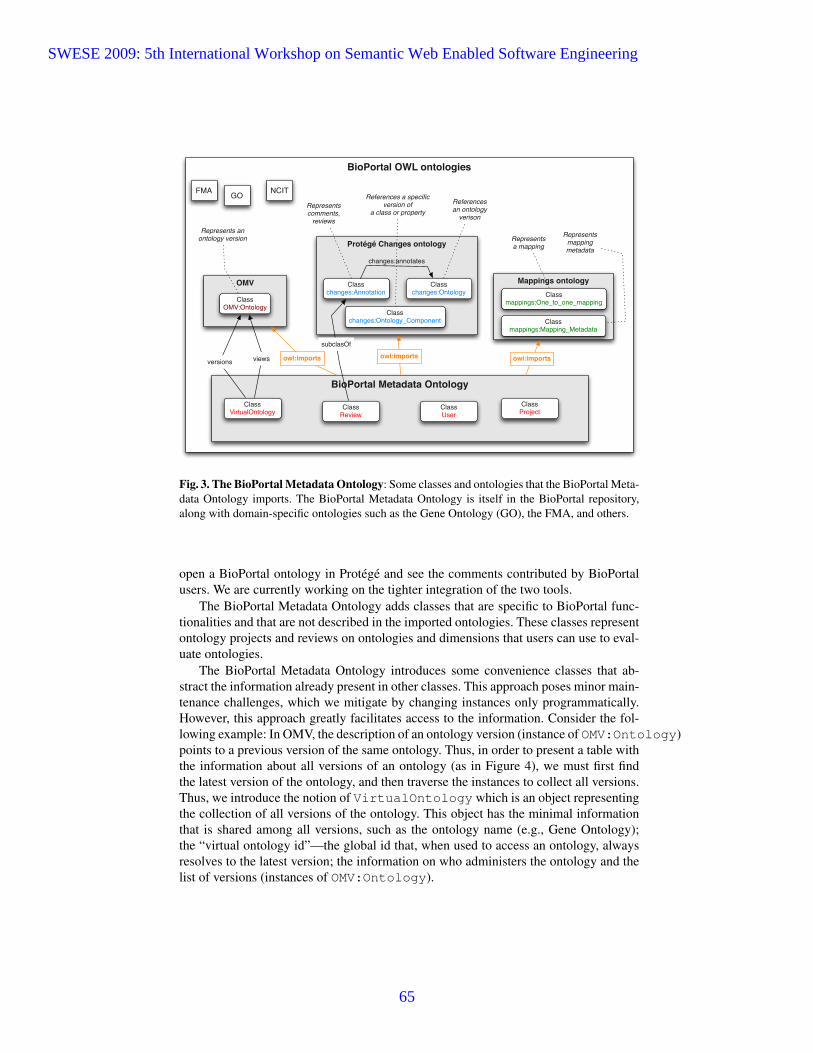
BioPortal OWL ontologies
BioPortal Metadata Ontology
OMV
Protégé Changes ontology
Mappings ontology
owl:imports owl:imports owl:imports
FMA NCITGO
ClassOMV:Ontology
Classchanges:Annotation
Classchanges:Ontology
Classchanges:Ontology_Component
Classmappings:One_to_one_mapping
Classmappings:Mapping_Metadata
Represents anontology version
Represents comments,
reviews
Referencesan ontology
verison
References a specificversion of
a class or property
Represents a mapping
Represents mappingmetadata
ClassVirtualOntology
ClassUser
ClassProjectClass
Review
versions views
changes:annotates
subclasOf
Fig. 3. The BioPortal Metadata Ontology: Some classes and ontologies that the BioPortal Meta-data Ontology imports. The BioPortal Metadata Ontology is itself in the BioPortal repository,along with domain-specific ontologies such as the Gene Ontology (GO), the FMA, and others.
open a BioPortal ontology in Protege and see the comments contributed by BioPortalusers. We are currently working on the tighter integration of the two tools.
The BioPortal Metadata Ontology adds classes that are specific to BioPortal func-tionalities and that are not described in the imported ontologies. These classes representontology projects and reviews on ontologies and dimensions that users can use to eval-uate ontologies.
The BioPortal Metadata Ontology introduces some convenience classes that ab-stract the information already present in other classes. This approach poses minor main-tenance challenges, which we mitigate by changing instances only programmatically.However, this approach greatly facilitates access to the information. Consider the fol-lowing example: In OMV, the description of an ontology version (instance of OMV:Ontology)points to a previous version of the same ontology. Thus, in order to present a table withthe information about all versions of an ontology (as in Figure 4), we must first findthe latest version of the ontology, and then traverse the instances to collect all versions.Thus, we introduce the notion of VirtualOntology which is an object representingthe collection of all versions of the ontology. This object has the minimal informationthat is shared among all versions, such as the ontology name (e.g., Gene Ontology);the “virtual ontology id”—the global id that, when used to access an ontology, alwaysresolves to the latest version; the information on who administers the ontology and thelist of versions (instances of OMV:Ontology).
SWESE 2009: 5th International Workshop on Semantic Web Enabled Software Engineering
65
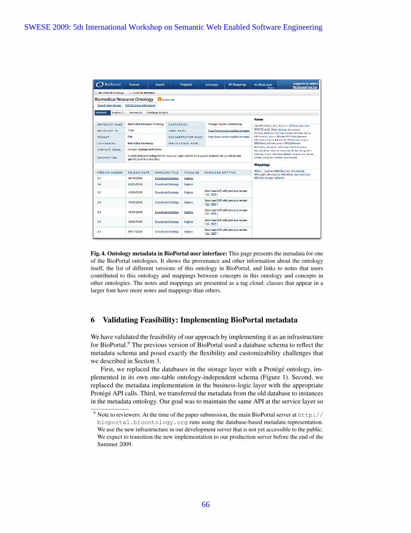
Fig. 4. Ontology metadata in BioPortal user interface: This page presents the metadata for oneof the BioPortal ontologies. It shows the provenance and other information about the ontologyitself, the list of different versions of this ontology in BioPortal, and links to notes that userscontributed to this ontology and mappings between concepts in this ontology and concepts inother ontologies. The notes and mappings are presented as a tag cloud: classes that appear in alarger font have more notes and mappings than others.
6 Validating Feasibility: Implementing BioPortal metadata
We have validated the feasibility of our approach by implementing it as an infrastructurefor BioPortal.9 The previous version of BioPortal used a database schema to reflect themetadata schema and posed exactly the flexibility and customizability challenges thatwe described in Section 3.
First, we replaced the databases in the storage layer with a Protege ontology, im-plemented in its own one-table ontology-independent schema (Figure 1). Second, wereplaced the metadata implementation in the business-logic layer with the appropriateProtege API calls. Third, we transferred the metadata from the old database to instancesin the metadata ontology. Our goal was to maintain the same API at the service layer so
9 Note to reviewers: At the time of the paper submission, the main BioPortal server at http://bioportal.bioontology.org runs using the database-based metadata representation.We use the new infrastructure in our development server that is not yet accessible to the public.We expect to transition the new implementation to our production server before the end of theSummer 2009.
SWESE 2009: 5th International Workshop on Semantic Web Enabled Software Engineering
66

that the user interface does not need to be modified and other applications that alreadyuse our REST service API can continue to use it.
Since we access the metadata ontology through the Protege API —which was suc-cessfully used in other projects to access in a scalable manner ontologies having morethan 8000 classes and 5 million instances 10— we predict with confidence that the newrepresentation of the metadata about ontologies will scale well. The version of BioPor-tal currently running on our development server uses this infrastructure successfully,thus validating the approach. We plan to release this implementation to production atend of August 2009.
At the time of this writing, the transition of metadata to ontology-based approach isnot complete. Currently, ontology details, ontology versions, and ontology views (seeSection 7) are represented as ontology instances. We are in the process of transitioningthe rest of the metadata.
7 Validating Extensibility: representing ontology views
As we discussed earlier, one of our main motivations to moving to the ontology-basedapproach was greater flexibility and adaptability of the metadata. We validated theseproperties by implementing support for ontology views in BioPortal, which did notpreviously exist. In our implementation we store only materialized views computedand submitted by the users, together with the metadata describing how the view wasgenerated (the language, engine, etc.)
In this context, a view is any subset of an ontology that is itself an ontology. A viewcan be created manually or automatically by a view-generation tool. For instance, ourcollaborators have several views of the Foundational Model of Anatomy (FMA) [15].One of the views represents the subset of the FMA that would be of interest to a ra-diologist; another view deals exclusively with Liver; yet another view focuses on therepresentation of neuroanatomy. The first of these views was generated manually, bystarting with the FMA in Protege and removing the unnecessary branches. The othertwo views are the results of queries in an extension of SPARQL that our collaboratorshave developed [17]. When ontology users generate and materialize the views, they of-ten want to share them with other researchers in the field. Thus, when users view a pagefor FMA, they can see not only its different versions, but also the views available for it.
7.1 Requirements for Representing Views
Discussions with our collaborators led to the following set of requirements on viewrepresentation:
– Each view is itself an ontology and can have metadata, be explorable, have reviews,statistics, and so on.
– A view is defined on a specific version of an ontology.
10 http://protegewiki.stanford.edu/index.php/Scalability_and_Tuning
SWESE 2009: 5th International Workshop on Semantic Web Enabled Software Engineering
67
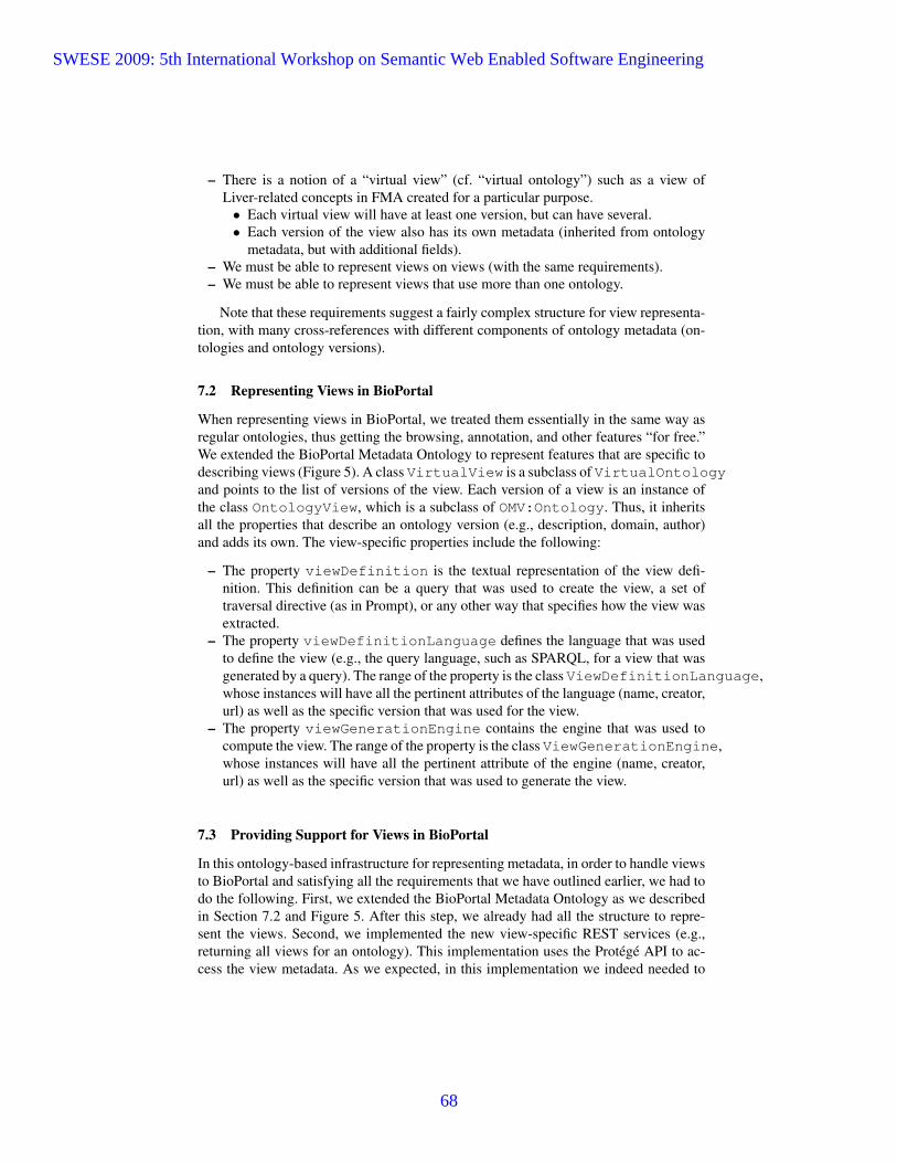
– There is a notion of a “virtual view” (cf. “virtual ontology”) such as a view ofLiver-related concepts in FMA created for a particular purpose.• Each virtual view will have at least one version, but can have several.• Each version of the view also has its own metadata (inherited from ontology
metadata, but with additional fields).– We must be able to represent views on views (with the same requirements).– We must be able to represent views that use more than one ontology.
Note that these requirements suggest a fairly complex structure for view representa-tion, with many cross-references with different components of ontology metadata (on-tologies and ontology versions).
7.2 Representing Views in BioPortal
When representing views in BioPortal, we treated them essentially in the same way asregular ontologies, thus getting the browsing, annotation, and other features “for free.”We extended the BioPortal Metadata Ontology to represent features that are specific todescribing views (Figure 5). A class VirtualView is a subclass of VirtualOntologyand points to the list of versions of the view. Each version of a view is an instance ofthe class OntologyView, which is a subclass of OMV:Ontology. Thus, it inheritsall the properties that describe an ontology version (e.g., description, domain, author)and adds its own. The view-specific properties include the following:
– The property viewDefinition is the textual representation of the view defi-nition. This definition can be a query that was used to create the view, a set oftraversal directive (as in Prompt), or any other way that specifies how the view wasextracted.
– The property viewDefinitionLanguage defines the language that was usedto define the view (e.g., the query language, such as SPARQL, for a view that wasgenerated by a query). The range of the property is the class ViewDefinitionLanguage,whose instances will have all the pertinent attributes of the language (name, creator,url) as well as the specific version that was used for the view.
– The property viewGenerationEngine contains the engine that was used tocompute the view. The range of the property is the class ViewGenerationEngine,whose instances will have all the pertinent attribute of the engine (name, creator,url) as well as the specific version that was used to generate the view.
7.3 Providing Support for Views in BioPortal
In this ontology-based infrastructure for representing metadata, in order to handle viewsto BioPortal and satisfying all the requirements that we have outlined earlier, we had todo the following. First, we extended the BioPortal Metadata Ontology as we describedin Section 7.2 and Figure 5. After this step, we already had all the structure to repre-sent the views. Second, we implemented the new view-specific REST services (e.g.,returning all views for an ontology). This implementation uses the Protege API to ac-cess the view metadata. As we expected, in this implementation we indeed needed to
SWESE 2009: 5th International Workshop on Semantic Web Enabled Software Engineering
68

BioPortal Metadata Instances
FMA, v.2.0Instance of
OMV:Ontology
FMA, v.1.0Instance of
OMV:Ontology
FMAInstance of
VirtualOntology
isVersionOf
isVersionOf
NeuroFMAInstance of VirtualView
virtualViewOf
NeuroFMA, v.0.1Instance of
OntologyView
NeuroFMA, v.0.2Instance of
OntologyView
isVersionOf
isViewOnisViewOn isVersionOf
NeuroFMA, v.1.0Instance of
OntologyView
isViewOn
isVersionOf
ClassOMV:Ontology
ClassVirtualOntology
hasVersion
hasVirtualView
ClassOntologyView
ClassVirtuallView
hasVersion
hasVirtualView
hasView subclassOf
subclassOf
isVersionOf
isVersionOf
isViewOfisVirtualViewOf
BioPortal Metadata Classes
Fig. 5. Classes and instances for representing views: The class VirtualView correspondsto the logical description of a specific view (e.g., NeuroFMA, which is an extraction of FMAconcepts relevant to Neuroimaging). It is a subclass of VirtualOntology because each viewis an ontology itself. Similarly, the class OntologyView extends the class OMV:Ontologyand describes specific versions of the view. The right-hand side of the figure shows some exampleinstances of these classes and properties that link them.
focus exclusively on the view-specific logic and structures and did not need to changeanything else (e.g., the application infrastructure or the architecture). Some of the func-tional requirements for handling the views crystallized while we were already workingon the implementation, and the only changes that were necessary were the changes tothe ontology itself. We did not need to change any database schemas or to add any ad-ditional structures (e.g., Hibernate stubs). The work that was required was limited toimplementing the logic for the services directly.
In comparison, adding views to the old (Hibernate-based) infrastructure, would haveinvolved some additional changes like: (a) creating new database tables (for views andvirtual views), (b) creating a number of foreign keys in order to represent superclass-subclass relationships and relationships expressed by object properties, (c) creating in-tegrity constraints to enforce data integrity along those relations, and (d) generate Hi-bernate classes (so called “entity beans”) from the database tables.
Figure 6 shows the extended ontology-metadata page that includes the informationabout the views.
8 Discussion and Lessons Learned
The new implementation of BioPortal infrastructure validates the use of ontologies andontology instances to represent all the metadata as well as system data for a repositoryof this kind. To the best of our knowledge, BioPortal is the first large-scale web-basedapplication that uses ontologies to represent its internal data. Our experience has shownthat using an ontology to describe the knowledge infrastructure of an application doesindeed provide the flexibility and adaptability that our application required. Our obser-
SWESE 2009: 5th International Workshop on Semantic Web Enabled Software Engineering
69

Fig. 6. The user interface for representing view metadata in BioPortal. The screenshot shows twoviews of the NCI Thesaurus. Each view has two different versions.
vations and discussions with developers show that it was easier and far more efficient toimplement view support that satisfied the requirements that we outlined in Section 7.1using this approach than using a database schema to describe the views and to linkthem to ontologies. It also enabled us to reuse much of the infrastructure that we havealready developed for ontology metadata, as we could treat views as special cases ofontologies. As our requirements for view representation continue to evolve, we knowthat our changes will be easy to implement as we will need only to evolve the ontologyrepresentation and the corresponding service implementations.
It is important to note that some of the design choices in the BioPortal Metadata On-tology are driven purely by application and implementation considerations. Thus, thereare parts of this ontology that are specific to the context of BioPortal implementation.We also made some of the ontology-design choices not because they were “ontologi-cally correct” in an abstract sense but because they simplified access to information (cf.VirtualOntology class to collect information about all versions of an ontology).Thus, we used the ontology not only as a conceptualization of our domain (metadatarepresentation) but also to represent the physical properties and location of the data.
There are a number of systems that use ontologies to represent some of their meta-data. These include Oyster [13], the alignment server [5], and Cupboard [3]. However,in these systems the items in the repository (such as ontologies or alignments) are sepa-rate from the part that represents the metadata. Furthermore, the ontology-based meta-data does not expand to representing internal system information. The ontology-basedrepresentation of metadata focuses on describing intrinsic properties of ontologies andother objects that are shared across applications.
SWESE 2009: 5th International Workshop on Semantic Web Enabled Software Engineering
70

Another class of applications that uses ontologies actively are semantic desktops(e.g., [6]). However, most semantic desktop applications do not represent system dataitself using the ontologies. Furthermore, semantic desktop applications focus on creat-ing a “semantic web” of desktop resources rather than representing the internal systemdata itself.
In our work, we have extended other metadata ontologies. In the future, we plan tointegrate other standards. Specifically, we plan to replace the Protege Mapping ontologythat we used here for expediency with an ontology that extends SKOS with mapping-specific metadata.
Our current effort leaves some questions and concerns, however. The main con-cern is scalability. While Protege is quite scalable and has been used with ontologiesthat have hundreds of thousands of classes and instances, we do not know how it willbehave with millions of instances describing metadata. As we noted in Section 6, wehave not yet moved mappings to this infrastructure. At the same time, we have just up-loaded one million new mappings to BioPortal. We are yet to test whether our currentProtege-based infrastructure will be sufficiently scalable for this number of mappings.If we learn that it is not, it will be the limitation of the Protege implementation itselfas modern triplestore implementations easily handle this amount of data. If scalabilityturns out to be an issue, we will transition to a triplestore to store the instances.
We would like to emphasize that our solution is not limited to the biomedical do-main. It so happens that our repository is a repository of biomedical ontologies. How-ever, there is nothing in the BioPortal Metadata Ontology itself or in our use of it thatis specific to biomedicine (except perhaps, the list of possible ontology categories). Wewill install the new infrastructure in other local BioPortal installations, such as the OORsandbox that we mentioned earlier (and that accepts ontologies in any domain).
Finally, the BioPortal software is open-source. The software is domain-independentand can be used for an ontology repository in any domain or for a domain-independentone. The BioPortal Metadata Ontology is available in BioPortal and can be accessedthrough the BioPortal user interface or its web services.11 We have created a snapshotof the instances of the BioPortal Metadata Ontology for our development version ofBioPortal. This ontology and instances can be accessed directly through the WebProtegeserver at http://bmir-protege-dev1.stanford.edu/webprotege/. 12
Acknowledgments
This work was supported by the National Center for Biomedical Ontology, under roadmap-initiative grant U54 HG004028 from the National Institutes of Health and by NIH grant HL087706.We are grateful to Jim Brinkeley, Todd Detwiller, Onard Mejino, and other members of the Struc-tural Informatics Group at Univesity of Washington for helping us identify requirements for viewsin BioPortal.
11 http://bioportal.bioontology.org12 Please use the Firefox browser to access the server. Select “BioPortal Metadata Ontology” and
then go to the “Individuals” tab to view the instances.
SWESE 2009: 5th International Workshop on Semantic Web Enabled Software Engineering
71

References
1. M. V. Bossche, P. Ross, I. MacLarty, B. V. Nu?elen, and N. Pelov. Ontology driven soft-ware engineering for real life applications. In 3rd International Workshop on Semantic WebEnabled Software Engineering (SWESE 2007), Innsubruk, Austria, 2007.
2. M. Brauer and H. Lochmann. An ontology for software models and its practical implicationsfor semantic web reasoning. In The 5th European Semantic Web Conference (ESWC 2008),pages 34–48, Tenerife, Spain, 2008. Springer.
3. M. dAquin and H. Lewen. Cupboard a place to expose your ontologies to applicationsand the community. In 6th European Semantic Web Conference (ESWC 2009), Heraklion,Greece, 2009.
4. J. Euzenat. An api for ontology alignment. In Third International Semantic Web Conference(ISWC 2004), pages 698–712, Hiroshima, Japan, 2004. Springer.
5. J. Euzenat. Alignment infrastructure for ontology mediation and other applications. InWorkshop on Mediation in Semantic Web Services, 2005.
6. T. Groza, S. Handschuh, K. Moeller, G. Grimnes, L. Sauermann, E. Minack, C. Mesnage,M. Jazayeri, G. Reif, and R. Gudjnsdttir. The nepomuk project - on the way to the socialsemantic desktop. In T. Pellegrini and S. Schaffert, editors, Proceedings of I-Semantics’ 07,pages 201–211. JUCS, Sept. 2007.
7. L. Hart, P. Emery, R. Colomb, K. Raymond, D. Chang, Y. Ye, E. Kendall, and M. Dutra. Us-age scenarios and goals for ontology definition metamodel. In 5th International Conferenceon Web Information Systems Engineering (WISE 2004), pages 596–607, Brisbane, Australia,2004. Springer.
8. T. Lehmann. A framework for ontology based integration of structured it-systems. In 3rdInternational Workshop on Semantic Web Enabled Software Engineering (SWESE 2007),Innsubruk, Austria, 2007.
9. N. F. Noy, A. Chugh, W. Liu, and M. A. Musen. A framework for ontology evolution incollaborative environments. In Fifth International Semantic Web Conference, ISWC, volumeLNCS 4273, Athens, GA, 2006. Springer.
10. N. F. Noy, N. Griffith, and M. A. Musen. Collecting community-based mappings in anontology repository. In 7th International Semantic Web Conference (ISWC 2008), Karlsruhe,Germany, 2008.
11. N. F. Noy, N. H. Shah, P. L. Whetzel, B. Dai, M. Dorf, N. Griffith, C. Jonquet, D. L. Rubin,M.-A. Storey, C. G. Chute, and M. A. Musen. Bioportal: ontologies and integrated dataresources at the click of a mouse. Nucleic Acids Research, 2009.
12. C. I. Nyulas, M. J. O’Connor, S. W. Tu, A. Okhmatovskaia, D. Buckeridge, and M. A. Musen.An ontology-driven framework for deploying jade agent systems. In IEEE/WIC/ACM Inter-national Conference on Intelligent Agent Technology, Sydney, Australia, 2008.
13. R. Palma, P. Haase, and A. Gomez-Perez. Oyster: sharing and re-using ontologies in a peer-to-peer community. In 15th international conference on World Wide Web (WWW 2006),pages 1009–1010, Edinburgh, Scotland, 2006. ACM.
14. R. Palma, J. Hartmann, and P. Haase. OMV: Ontology Metadata Vocabulary for the SemanticWeb. Technical report, http://ontoware.org/projects/omv/, 2008.
15. C. Rosse and J. L. V. Mejino. A reference ontology for bioinformatics: The FoundationalModel of Anatomy. Journal of Biomedical Informatics., 2004.
16. H. H. Shahri, J. A. Hendler, and A. A. Porter. Software configuration management usingontologies. In 3rd International Workshop on Semantic Web Enabled Software Engineering(SWESE 2007), Innsubruk, Austria, 2007.
17. M. Shaw, L. T. Detwiler, J. F. Brinkley, and D. Suciu. Generating application ontologiesfrom reference ontologies. In AMIA Annual Symposium, Washington, DC, 2008.
SWESE 2009: 5th International Workshop on Semantic Web Enabled Software Engineering
72

Integrating Linked Data Driven SoftwareDevelopment Interaction into an IDE
Aftab Iqbal, Oana Ureche, and Michael Hausenblas
DERI, National University of Ireland, Galway, Ireland{firstname.lastname}@deri.org
Abstract. With “Linked Data Driven Software Development” (LD2SD)we have introduced a light-weight, linked data-based framework that al-lows to integrate software artefacts, such as version control systems andissue trackers, as well as discussion forums. The so created interlinkeddata-space enables uniform query and browsing facilities. In this paperwe elaborate on the interaction part of LD2SD, and demonstrate howthe LD2SD-interaction can be integrated into an Integrated Develop-ment Environment (IDE). We have performed an end-user evaluationand report on our findings and outline future steps.
Key words: linked data, interaction, Software Engineering, IDE
1 Introduction
In the software development process, both humans and so called software arte-facts are involved (cf. Fig. 1 from [IUHT09]). Some of the software artefacts aredirectly under the control of the developers, while others are shared among usersand developers, such as bug tracking system, documentation, discussion forumsetc.
Developers use different mediums of communication to interact with eachother and to solve problems. For example, Java source code and bugs are of-ten discussed in forums or project mailing lists. However, the interconnectionsamong software artefacts in the various data sources are typically not explicit.Developers nowadays have to perform keyword-based searches on the Web tofind examples for source code or need to manually trace discussions about a bugon a blog. The attraction of using semantic technologies in order to address thisissue is based on the idea to transform software artefacts into an conceptuallyorganised and interlinked data-space, incorporating data from different softwareartefacts [DB08].
With “Linked Data Driven Software Development” (LD2SD) [IUHT09] wehave introduced a linked data [BHBL09] based, light-weight framework thatallows to integrate software artefacts. The so created interlinked data-space en-ables uniform query and browsing facilities. In this paper we elaborate on theinteraction [Hea08] part of LD2SD, and demonstrate how the LD2SD-interactioncan be integrated into an Integrated Development Environment (IDE).
SWESE 2009: 5th International Workshop on Semantic Web Enabled Software Engineering
73

2 Aftab Iqbal, Oana Ureche, and Michael Hausenblas
Fig. 1: The software development process, including its participants.
With the work at hand, we aim at enabling Java developers to explore relatedinformation about software artefacts. We present an interface that developers canuse as a plug-in in their development environment (IDE), such as Eclipse1 tofind related information about Java source code, which might be found in a bugtracking systems, Subversion logs or in a blog discussion.
The paper is structured as follows: in Section 2, we discuss our LD2SD-based approach. We report on a concrete use case and an implementation of theLD2SD interaction in Section 3. The Section 4 presents the results from an end-user evaluation. In Section 5 we review related and existing work and eventually,in Section 6, we conclude our work and give an outlook on future work regardingLD2SD.
2 Linked Data Driven Software Development (LD2SD)
There are manifold ways to integrate different software artefacts. In order toprovide a unified access to the different software artefacts, one needs to interlinkand integrate these software artefacts, as we have argued in [IUHT09]. The over-all concept of Linked Data Driven Software Development (LD2SD)—depicted in
1 http://www.eclipse.org/
SWESE 2009: 5th International Workshop on Semantic Web Enabled Software Engineering
74

Integrating LD2SD into an IDE 3
Fig. 2: The layered LD2SD approach for software artefacts integration.
Fig. 2 from [IUHT09]—is a layered, linked data based integration of softwareartefacts.
In this paper we elaborate on the top-most part of the LD2SD approach, theinteraction part. We have chosen a particular setup, assuming a Java developerusing Eclipse. The goal was to create an Eclipse plug-in that allows the developerto consume LD2SD data.
To enable a rapid development of our demonstrator, we decided to build uponan already available indexing service for the integration layer. The data layer,including RDFication and Interlinking was reused from [IUHT09].
In Fig. 3 our setup is described in detail:
1. RDFizing the software artefacts based on the linked data principles, yieldingLD2SD datasets;
2. Using an indexing engine, Apache Lucene/Solr2 to index the LD2SD datasets;3. Develop a lookup service on top of the indexing service to enable keyword-
based search over the LD2SD datasets;4. Deliver the information to the developer via an Eclipse plug-in.
In order to achieve the linked data functionality for software artefacts, oneneeds to generate RDF data and interlink them. We have shown elsewhere [IUHT09]how to achieve the RDFizing and interlinking of the software artefacts.
2 http://lucene.apache.org/solr/
SWESE 2009: 5th International Workshop on Semantic Web Enabled Software Engineering
75

4 Aftab Iqbal, Oana Ureche, and Michael Hausenblas
Fig. 3: LD2SD Interaction Setup.
SWESE 2009: 5th International Workshop on Semantic Web Enabled Software Engineering
76

Integrating LD2SD into an IDE 5
After RDFizing and interlinking, the datasets are indexed by the Apache Solrindexing service. Each document is split into multiple documents based on thenumber of resources described in it and each resource is indexed as a separatedocument. The advantage of splitting an RDF document into sub-documentsis that the lookup service returns the specific resource as a result rather thanthe whole document. For example, the Java2RDF [IUHT09] parser generates asingle RDF dump of a software project, which contains description about theJava packages, the Java source in each package and the Java methods in eachclass along with JavaDoc.
Fig. 4: Document indexing process.
The Document Indexer (cf. Fig. 4) indexes each package, Java classes andJava methods as a separate document. This approach allows the user to queryfor a Java class or a Java method and the Apache Solr indexing service willreturn the specific document instead of the RDF document for the entire softwareproject. In order to query for the documents stored by the indexing service,the lookup service enables keyword-based queries against the indexing service.Although, different software artefacts are indexed by the indexing service, theDocument Indexer does not only store content, but also the URI of documentand the type of document, for example JavaClass, Package, Discussion etc.
SWESE 2009: 5th International Workshop on Semantic Web Enabled Software Engineering
77

6 Aftab Iqbal, Oana Ureche, and Michael Hausenblas
3 Implementation
For the concrete implementation of the LD2SD plug-in, we have chosen Eclipse,a popular Java IDE. Software developers spend most of their time in IDEs suchas Eclipse, though need to access bug tracking system to log bugs or discussdevelopment issues in blogs or mailing lists, etc. As we wanted to offer a cross-platform, extensible solution, we decided to implement the actual interface ofthe plug-in as a linked data application [Hau09] based on HTML and utilisingthe Eclipse-internal Web browser. Alternatively, the LD2SD-interaction is alsopossible via a standalone Web browser.
3.1 Interaction via Eclipse plug-in
To enable developers to search for documents or to find related informationabout software artefacts without leaving their development environment, we haveimplemented an Eclipse plug-in. This enables the developer to retrieve relatedinformation about entities (such as classes, methods, etc.) in the Java sourcecode of a software project. Say, the developer is interested in related informationabout a certain Java class. One way to trigger the LD2SD plug-in is to rightclick on the Java class and select the “Show Related Information” command (cf.bottom of Fig. 5) from the context menu.
Fig. 5: Triggering the plug-in via the context menu.
In response, the lookup-service provides URIs as entry points and issuesautomatically a SPARQL query, which is executed on the entire LD2SD datasetsto retrieve related information about that Java class as shown in Fig. 6.
SWESE 2009: 5th International Workshop on Semantic Web Enabled Software Engineering
78
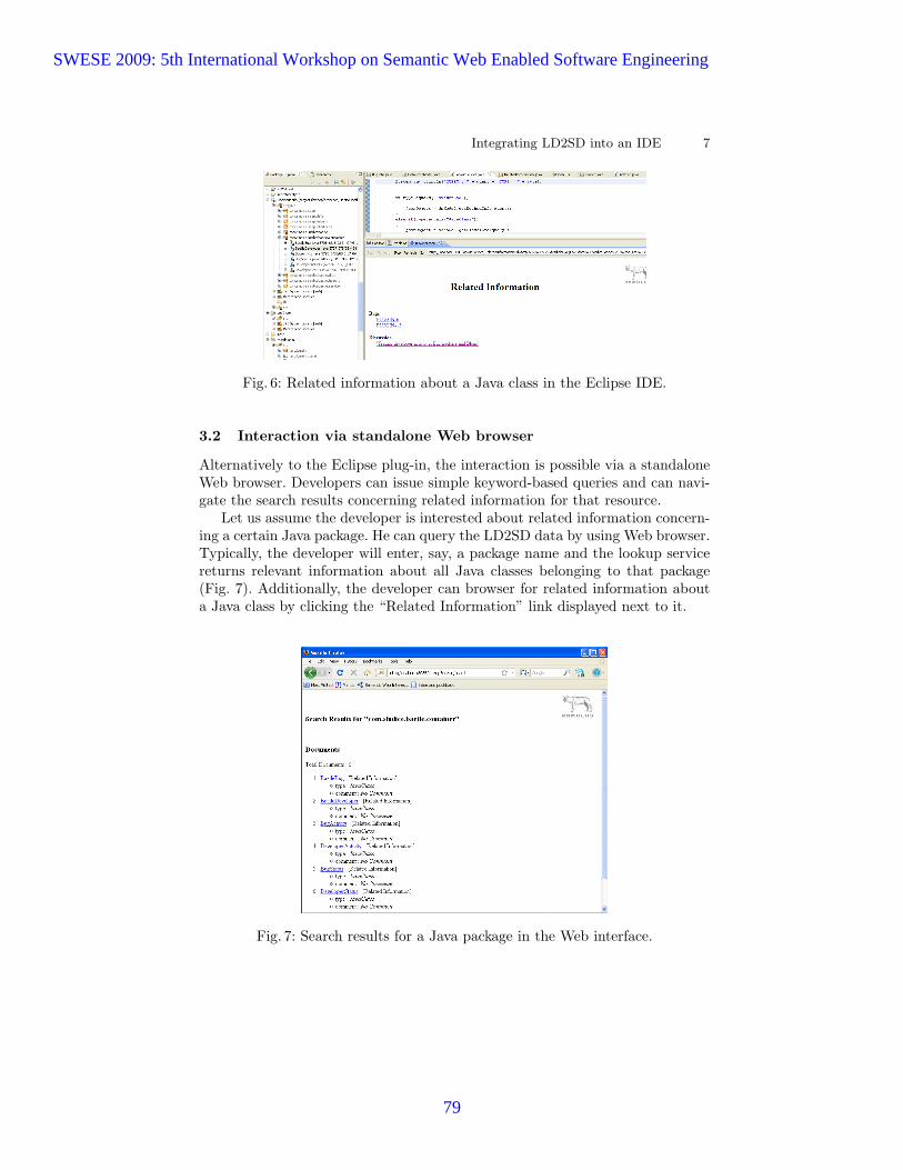
Integrating LD2SD into an IDE 7
Fig. 6: Related information about a Java class in the Eclipse IDE.
3.2 Interaction via standalone Web browser
Alternatively to the Eclipse plug-in, the interaction is possible via a standaloneWeb browser. Developers can issue simple keyword-based queries and can navi-gate the search results concerning related information for that resource.
Let us assume the developer is interested about related information concern-ing a certain Java package. He can query the LD2SD data by using Web browser.Typically, the developer will enter, say, a package name and the lookup servicereturns relevant information about all Java classes belonging to that package(Fig. 7). Additionally, the developer can browser for related information abouta Java class by clicking the “Related Information” link displayed next to it.
Fig. 7: Search results for a Java package in the Web interface.
SWESE 2009: 5th International Workshop on Semantic Web Enabled Software Engineering
79

8 Aftab Iqbal, Oana Ureche, and Michael Hausenblas
4 Evaluation
To evaluate our approach, we have prepared data from a software project (bugtracking data, subversion logs, blogs and Java source code). We assessed the us-ability of our Eclipse plug-in approach via end-user evaluations requiring partic-ipants to perform a set of tasks. We measured the time it took them to completethe tasks and asked questions around the usability.
No. Software Artefact Familiarity (%)
1 Eclipse IDE 80
2 Bug tracking systems 60
3 Discussion blogs 100
4 Subversion plug-in for bug tracking system 42
5 Mylyn plug-in for Eclipse IDE 45
Table 1: Familiarity of the participants with the tools.
Twelve participants took part in the evaluation. The participants have de-velopment experience ranging from one to five years with different backgrounds.Table. 1 shows the familiarity of the participants with the different softwareartefacts.
The participants were asked to carry out a set of tasks on the test data:
Task 1 Identify all blog posts that mention a specific Java class.Task 2 Identify all bugs that have been fixed by modifying a specific Java class.Task 3 Identify all developers that are working on a Java package.Task 4 Identify all blog posts that mention a specific Java package.Task 5 Identify all bugs that belong to a specific Java package.
For the Task 2 and Task 5 we have installed a Subversion plug-in for, whichshows the logs for bugs, if any. We conducted our evaluation in two phases:
Manual Approach In the first phase, we gave participants access to the soft-ware project, the bug tracking system, and the blog. The participants searchedthrough blog posts, traversed bug reports and searched source files for au-thors to carry out each task.
Plug-in Approach In the second phase, we asked participants to carry out thetasks by using our LD2SD plug-in for the Eclipse IDE.
In the first phase, we found that participants used different heuristics tolist the results of each task. After the second phase, we asked the participantsto compare the results of both approaches. We found that some participantsmissed certain results using the first approach while carrying out the tasks.Further, participants apparently had difficulties going through each bug reportto identify corresponding bug entries in Subversion. During the evaluation, weasked the participants to answer a set of yes/no questions as shown in Table. 2.
SWESE 2009: 5th International Workshop on Semantic Web Enabled Software Engineering
80

Integrating LD2SD into an IDE 9
Question Yes No
Is the tool useful to discover related information? 12 0
Does our approach added value compared to the usual explo-ration of related information?
12 0
Is the design and layout of the tool suited enough for usage? 9 3
Does the integration of software artefacts as an Eclipse plug-inoffer an advantage?
10 2
Table 2: User-study regarding tool.
The time for each task has been measured in both phases of the evaluation;the resulting graph (Fig. 8) is plotted based on the average time each participantspent in carrying out the task.
A big majority of the participants found our approach of extracting relatedinformation and presenting it in an integrated manner inside Eclipse interestingand useful. For example: “... single point access within the Eclipse IDE seems anatural tool to use. It provides information much faster than accessing individualsources. The integrated view is very convenient”.
Participants liked the LD2SD approach to interlink the Java sources withsubversion logs and bugs using linked data principles. They were able to answerquestions such as: (1) who has fix the certain bug and which source files he hasmodified in fixing the bug, (2) who should i talk to, and (3) which blog postsare talking about that certain bug; an exemplary comment highlights this: “...it saves time for a developer and provides a unique interface to have a look atall relevant information in a single view ... all relevant information is availableon a single click ... the idea looks promising, the tool would be more useful as itevolves and add features”.
The evaluation helped us identifying the limitations of the tool as well. Someparticipants commented on the interface: “... interface is relatively small, mightbe an usability issue for large amount of data ... would be interesting to see how
Fig. 8: Time required to perform tasks (manual vs. plug-in approach).
SWESE 2009: 5th International Workshop on Semantic Web Enabled Software Engineering
81
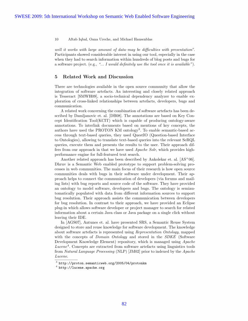
10 Aftab Iqbal, Oana Ureche, and Michael Hausenblas
well it works with large amount of data–may be difficulties with presentation”.Participants showed considerable interest in using our tool, especially in the casewhen they had to search information within hundreds of blog posts and bugs fora software project. (e.g., “... I would definitely use the tool once it is available”).
5 Related Work and Discussion
There are technologies available in the open source community that allow theintegration of software artefacts. An interesting and closely related approachis Tesseract [SMWH09], a socio-technical dependency analyzer to enable ex-ploration of cross-linked relationships between artefacts, developers, bugs andcommunication.
A related work concerning the combination of software artefacts has been de-scribed by Damljanovic et. al. [DB08]. The annotations are based on Key Con-cept Identification Tool(KCIT) which is capable of producing ontology-awareannotations. To interlink documents based on mentions of key concepts, theauthors have used the PROTON KM ontology3. To enable semantic-based ac-cess through text-based queries, they used QuestIO (Question-based Interfaceto Ontologies), allowing to translate text-based queries into the relevant SeRQLqueries, execute them and presents the results to the user. Their approach dif-fers from our approach in that we have used Apache Solr, which provides high-performance engine for full-featured text search.
Another related approach has been described by Ankolekar et. al. [AS+06].Dhruv is a Semantic Web enabled prototype to support problem-solving pro-cesses in web communities. The main focus of their research is how open sourcecommunities deals with bugs in their software under development. Their ap-proach helps to connect the communication of developers (via forums and mail-ing lists) with bug reports and source code of the software. They have providedan ontology to model software, developers and bugs. The ontology is semiau-tomatically populated with data from different information sources to supportbug resolution. Their approach assists the communication between developersfor bug resolution. In contrast to their approach, we have provided an Eclipseplug-in which allows software developer or project manager to search for relatedinformation about a certain Java class or Java package on a single click withoutleaving their IDE.
In [AGS07], Antunes et. al. have presented SRS, a Semantic Reuse Systemdesigned to store and reuse knowledge for software development. The knowledgeabout software artefacts is represented using Representation Ontology, mappedwith the concepts of Domain Ontology and stored in the SDKE (SoftwareDevelopment Knowledge Element) repository, which is managed using ApacheLucene4. Concepts are extracted from software artefacts using linguistics toolsfrom Natural Language Processing (NLP) [JM02] prior to indexed by the ApacheLucene.3 http://proton.semanticweb.org/2005/04/protonkm4 http://lucene.apache.org
SWESE 2009: 5th International Workshop on Semantic Web Enabled Software Engineering
82
Integrating LD2SD into an IDE 11
In [KBT07], Kiefer et. al. have presented EvoOnt5, a software repository dataexchange format based on OWL. EvoOnt includes software code, code reposi-tory and bug information. The authors have used the iSPARQL6 engine whichis an extension of SPARQL, to query for similar software entities. iSPARQL isbased on virtual triples which are used to configure similarity joins [Coh00].Their approach differs from our approach in that we have provided a methodol-ogy [IUHT09] to integrate the software artefacts by RDFizing and interlinkingthem.
Mylyn7 is a sub-system for the Eclipse IDE allowing multitasking for devel-oper and task management. It provides the means to render bug-related data inthe Eclipse IDE for developers to work efficiently in their development environ-ment without having to log in to the Web based application to update or createnew bugs. Mylyn is limited to issue trackers such as JIRA8 or Bugzilla9, andhence not able to cope with the variety of software artefacts as we desire it.
Further, there are plug-ins10 which integrate Subversion with bug trackers.The plug-in display all Subversion commit messages related to a specific issue.
To the best of our knowledge there is no tool available that is able to dealwith software artefacts in a flexible and open way as we have provided it basedon the LD2SD approach.
In [IUHT09] we have already demonstrated the methodology of RDFizing andinterlinking heterogeneous software artefacts. In LD2SD we address the issue ofheterogeneous software artefacts by using a common data model (RDF) alongwith global unique identifiers (URIs). The current version of LD2SD relies onthe open access to the different data sources to extract metadata, interlink andquery them. As pointed out in [IUHT09], a number of ontologies (BAETLE,FOAF, SIOC, iCalendar) have been used to deal with the domain semantics.
6 Conclusion and Future Work
We have motivated and described LD2SD, a light-weight, linked data-basedframework allowing to integrate software artefacts, such as version control sys-tems and issue trackers, as well as discussion forums. In this paper we havefocused on the interaction layer, that is, providing means for developers to con-sume LD2SD-based data from existing software artefacts.
Based on a concrete use case and implementation of the LD2SD interactionpart, an Eclipse plug-in, we have conducted an end-user evaluation. Our evalua-tion shows that the plug-in is relatively easy to use and valuable for developers.
Our future work will focus on the improvement of the current Eclipse plug-in. Currently, our keyword-based lookup service returns a list of all relevant5 http://www.ifi.uzh.ch/ddis/evo/6 http://www.ifi.uzh.ch/ddis/isparql.html7 http://www.eclipse.org/mylyn/8 http://www.atlassian.com/software/jira/9 http://www.bugzilla.org/
10 http://subversion.tigris.org/links.html#misc-utils
SWESE 2009: 5th International Workshop on Semantic Web Enabled Software Engineering
83

12 Aftab Iqbal, Oana Ureche, and Michael Hausenblas
documents, without ranking. Based on [GGM97] we will focus on the rankingof the results, taking into account the context of the developer. Motivated bythe outcome of the evaluation, we want to provide plug-ins for other IDEs, forexample for NetBeans.
We want to integrate even more software artefacts (such as mailing lists, Javatest cases, developers profiles, etc.) and aim at increasing the interlinking qualityand quantity.
Eventually, we plan to perform follow-up evaluations on a real world opensource project with a broader target audience (real world developers, etc.).
Acknowledgements
Our work has partly been supported by the European Commission under GrantNo. 217031, FP7/ICT-2007.1.2—“Domain Driven Design and Mashup OrientedDevelopment based on Open Source Java Metaframework for Pragmatic, Reli-able and Secure Web Development”(Romulus)11.
References
[AGS07] B. Antunes, P. Gomes, and N. Seco. SRS: A Software Reuse System basedon the Semantic Web. In 3rd International Workshop on Semantic WebEnabled Software Engineering (SWESE) of the 4th European Semantic WebConference (ESWC 2007), Innsbruck, Austria, 2007.
[AS+06] A. Ankolekar, K. Sycara, , J. Herbsleb, R. Kraut, and C. Welty. Supportingonline problem-solving communities with the Semantic Web. In Proceed-ings of the 15th International Conference on World Wide Web, Edinburgh,Scotland, 2006.
[BHBL09] C. Bizer, T. Heath, and T. Berners-Lee. Linked Data—The Story So Far.Special Issue on Linked Data, International Journal on Semantic Web andInformation Systems (IJSWIS), page to appear, 2009.
[Coh00] W. W. Cohen. Data Integration Using Similarity Joins and a Word-BasedInformation Representation Language. In ACM TOIS, pages 288–321, 2000.
[DB08] D. Damljanovic and K. Bontcheva. Enhanced Semantic Access to Soft-ware Artefacts. In 5th International Workshop on Semantic Web EnabledSoftware Enginering (SWESE 2008), Karlsruhe, Germany, 2008.
[GGM97] L. Gravano and H. Garcia-Molina. Merging Ranks from HeterogeneousInternet Sources. In VLDB97, Proceedings of 23rd International Conferenceon Very Large Data Bases, pages 196–205, Athens, Greece, 1997.
[Hau09] M. Hausenblas. Linked Data Applications. First Community Draft,Linked Data Research Centre, 2009. http://linkeddata.deri.ie/tr/
2009-ld2webapp.
[Hea08] T. Heath. How Will We Interact with the Web of Data? IEEE InternetComputing, 12(5):88–91, 2008.
11 http://www.ict-romulus.eu/
SWESE 2009: 5th International Workshop on Semantic Web Enabled Software Engineering
84

Integrating LD2SD into an IDE 13
[IUHT09] A. Iqbal, O. Ureche, M. Hausenblas, and G. Tummarello. LD2SD: LinkedData Driven Software Development. In 21st International Conferenceon Software Engineering and Knowledge Engineering (SEKE 09), Boston,USA, 2009.
[JM02] P. Jackson and I. Moulinier. Natural Language Processing for Online Ap-plications: Text Retrieval, Extraction and Categorisation. John BenjaminsPublishing Company, Amsterdam, Netherlands, Wolverhampton, UnitedKingdom, 2002.
[KBT07] C. Kiefer, A. Bernstein, and J. Tappolet. Mining Software Repositorieswith iSPARQL and a Software Evolution Ontology. In Proceedings ofthe ICSE International Workshop on Mining Software Repositories (MSR),Minneapolis, MA, 2007.
[SMWH09] A. Sarma, L. Maccherone, P. Wagstrom, and J. Herbsleb. Tesseract: In-teractive Visual Exploration of Socio-Technical Relationships in SoftwareDevelopment. In International Conference on Software Engineering (ICSE2009), Vancouver, Canada, 2009.
SWESE 2009: 5th International Workshop on Semantic Web Enabled Software Engineering
85

Data Modeling and Harmonization with OWL: Opportunities and Lessons Learned
John L. McCarthy1, Denise Warzel2, Elisa Kendall3, Bruce Bargmeyer1,
Harold Solbrig4, Kevin Keck1 and Fred Gey5
1Lawrence Berkeley National Laboratory, 1 Cyclotron Rd, Berkeley, CA 2National Cancer Institute, National Institutes of Health, Bethesda, MD
3Sandpiper Software, Los Altos, CA 1Mayo Clinic, Rochester, MN
5School of Information Management, University of California, Berkeley
Abstract. Experience from recent projects helps illuminate the promises and limitations of OWL to specify, review, refine, harmon-ize and integrate diverse data and concept models. One of the attrac-tive features of OWL is that it can be used by inference engines to help augment queries through inferred semantic relationships. But OWL, like SQL, is only a computer programming language. Using it to review and refine representations of data, metadata, and concept systems, including terminologies, thesauri, and ontologies, requires a well-defined abstraction layer which itself can be specified in terms of OWL. In order to optimize, harmonize and integrate such information effectively for large scale projects, OWL definitions and relationships should be specified in terms of a standard metamodel, such as ISO/IEC 11179-3, Edition 3.
Keywords: OWL, metadata, UML, ISO 11179, metadata registration, data modeling
1 Introduction
Information technology experts are beginning to recognize the need to combine multi-disciplinary data, metadata, and concepts from a variety of related fields to address complex and/or large scale problems. Doing so re-quires integrating content from diverse communities with long established but different terminologies, concepts, and ways of naming and organizing their data. This paper explores how OWL (Web Ontology Language [1]) can be used to help advance decades-long efforts to represent, manage, harmon-ize, and integrate metadata and semantics for concept systems (including taxonomies, thesauri, and ontologies), databases, data elements, and value domains (i.e., data types, and sets of valid values). For the purpose of this paper, the word “ontology” refers to a domain specific conceptualization, for a specific purpose [2].
As elaborated further below, OWL, like other computer languages, is in-tended for a specific purpose, it is a declarative representation language for representing knowledge and used for authoring ontologies. OWL does not provide built-in, standard modeling constructs to harmonize between ontol-ogies, let alone describe their interrelationships or external relations to data, metadata about databases or application systems, nor to manage the evolu-tion of such relationships over time. Several recent projects illustrate how OWL provides some very useful constructs that complement capabilities of other software engineering technologies and paradigms and can be used in conjunction with them to support new ways to model concept and data se-mantics. One such paradigm for concept and data management is the meta-data registry, (MDR) particularly those based on the ISO/IEC 11179 Meta-
SWESE 2009: 5th International Workshop on Semantic Web Enabled Software Engineering
86

data registries (MDR) – Part 3: Registry metamodel and basic attributes Edi-tion 3 (E3), [3] and related ISO/IEC 19763 Metamodel Framework for Inte-roperability (MFI) [4] specifications which are being extended to represent relationships between and across ontologies, as well as relationships be-tween ontologies, terminologies, data models and web services that imple-ment or reuse them.
Our discussion is based in part on results from three recent data and se-mantic modeling projects that all employed OWL, each for different pur-poses. The first of these projects used the Ontology Definition Metamodel
(ODM)[5] to represent the BRIDG1 model [6, 7], and transform it to OWL
to help analyze and identify potential shortcomings in BRIDG [8]. The second project attempted to use an automatic ODM-based conversion tool to transform the LexGrid [9] terminology model from XML Schema into OWL. The eXtended Metadata Registry (XMDR) project [10] has used OWL in conjunction with other tools to develop a prototype system that im-plements extensions and enhancements included in the current CD of ISO/IEC 11179 E3, Standard. Lessons learned from these efforts will be highlighted in the sections that follow.
2 Background and Motivation
Descriptions of data, how it was collected, and what it means are an es-sential component of modern information systems. These descriptions, called metadata (i.e., data about data), help ensure that data is interpretable by both humans and computers over time. Large organizations like the U.S. Environmental Protection Agency (EPA), National Cancer Institute (NCI), and Department of Defense (DOD) perform research that utilizes large amounts of data drawn from a variety of disparate systems. They have long recognized the need for standardized metadata registry systems to help manage and harmonize data elements from different databases and applica-tion systems [10]. At the same time, such organizations, along with others in Europe and Asia, were among the first proponents of national and inter-national standards for terminologies, thesauri, concept systems and ontolo-gies2.
In parallel, NCI and small communities of data modelers and software engineers have been using ontologies to extend the capabilities of their me-tadata registry and software systems to enhance the semantics, identify po-tentially duplicate metadata, and increase the potential for reuse [11, 12]. Ontologies and ontology tools can facilitate automation supporting categori-zation and reasoning about increasingly massive amounts of data and meta-data that many large organizations have to cope with. Despite apparent po-tential benefits from cross pollination between data management, data governance, and related disciplines that use semantic technologies, little progress has been made in marrying the two communities outside of a few isolated United States and European government agency activities. The overlap between the enterprise data and semantic web communities is very small at present, as evidenced by discussions at recent workshops at the En-
1 The Biomedical Research Integrated Domain Group (BRIDG) Model is a domain
analysis model that describes biomedical/clinical research data.
SWESE 2009: 5th International Workshop on Semantic Web Enabled Software Engineering
87
terprise Data World3 and Semantic Technology Conferences4 earlier this year.
The National Cancer Institute (NCI)’s data management infrastructure, comprised of the Cancer Data Standards Registry (caDSR) and Enterprise Vocabulary System (EVS), is a notable exception to the low level of syner-gy between data management and ontology communities. caDSR and EVS have enabled NCI to collect, harmonize and integrate detailed metadata and concepts describing some 5,500 data elements and case report forms in hun-dreds of clinical studies from over 90 different projects. The semantics of these elements are tied directly to over 10,000 concepts drawn from the NCI’s Enterprise Vocabulary System (EVS) [13]. The U.S. Environmental Protection Agency's Environmental Data Registry (EDR), which has infor-mation covering water, air, and soil in databases and application systems, with many data elements, value domains, and terms from different terminol-ogy systems (though not directly linked) also illustrates the synergy between utilization of terminology systems and data management (e.g., GEMET, Chemical Substances Taxonomy, etc.) [14].
Use of formal languages such as OWL to represent data semantics linked to terminologies can provide a tremendous opportunity for novel research and discovery, in particular if the expression of the data semantics is based on a well-defined, shared metadata model and the terminologies are well formed. World Wide Web Consortium founder Tim Berners-Lee, speaking about the “semantic web,” stated that “The concept of machine-understandable documents… indicates a machine's ability to solve a well-defined problem by performing well-defined operations on existing well-defined data. Instead of asking machines to understand natural language, it involves asking people to make the extra effort” [15]. (Italics are ours). The implication is that people will have to take additional steps to create ma-chine-understandable documents. Utilizing ISO/IEC11179-3 Ed 3 integrated metamodel for data and concept systems provides well-defined data descrip-tions for use with the OWL representation , making data comparable within and across communities because the common structure of the metadata al-lows programmers to develop well-defined operations for machine interpre-tation. Recent projects have demonstrated the power of such integrated in-frastructures, but achievement of this level of integration does not come automatically simply by adopting a new language such as OWL [16].
3 Levels of Abstraction for Data, Metadata and Ontologies
To elucidate these ideas more concretely, consider a hypothetical exam-ple of something in the real world about which we want to capture data, re-presentation of the data in a database, information about this data (metada-ta), and a concept system fragment (which could be part of an ontology). Figure 1 shows this example with three “levels” of information – concepts, data and metadata, and some of the relationships between them. The picture at the top left represents two streams and a lake, each with its own monitor-ing station (A, B, and X). A formalized concept system could describe the relationships between these bodies of water and monitoring stations. The ta-ble at the top right contains three rows of data, one collected from each of
3 See http://edw2009.wilshireconferences.com/. 4 See http://www.semtech2009.com/.
SWESE 2009: 5th International Workshop on Semantic Web Enabled Software Engineering
88

those stations on a particular date. Each column in the table contains data for a particular observation of the variables (ID, Date, Temperature, and Mercury contamination), while each row represents values observed at a particular monitoring station location (A represents the row of values for the Lake monitoring station, B the values for the second monitoring station, and X the values for the monitoring station further downstream
ID Date Temp Hg
A Jan-09-02 4.4 4
B Jan-09-02 9.3 2
X Jan-09-02 6.7 78
Sign Datatype Definition Units
ID textMonitoring Station Identifier
not applicable
Date date Observation date yy-mm-dd
Temp number
ambient Temperature (to 0.1 degree C)
degrees Celcius
Hg number
amount of mercury per unit volume of water
micrograms per liter
Data Table:
Metadata Table:
ological Radioactive
Contamination
lead cadmiummercury
Chemical
Figure 1: Data, Metadata, and Concept Systems
Concept System Fragment
A
X B
The table on the lower right contains “metadata” – a description of the meaning and purpose of each column in the Data table -- (ID, Date, Temp, and Hg). Each column in the metadata table (i.e. Sign, Datatype, Descrip-tion, Units) contains a piece of information about a column of the Data ta-ble, while each row represents a particular column in the Data table. De-picted at the lower left is an excerpt from the General European Multi-lingual Environmental Thesaurus (GEMET) concept system that shows Contamination of a body of water in three forms (Biological, Radioactive, and Chemical), along with three kinds of Chemical Contaminants, namely mercury, lead, and cadmium. Dotted lines in Figure 1 indicate some of the important relationships between different components of the three types of information. For example, the ID with the value “A” in the first cell of the first row of the Data table is the identifier for the Lake monitoring station in the picture. All the values in that row refer to the monitoring station with the ID “A”. Likewise the first cell in the bottom row of the Metadata table re-fers to the label of the fourth column in the Data table and all the values in that metadata row pertain to the values in that column e.g. the cell of the second column in the bottom row refers to the Datatype of the fourth col-umn in the Data table. Another dotted line shows a relationship between the Definition cell for the bottom row of the Metadata table (which relates to the 4th column of the Data table) to a particular item in the hierarchical diagram of terms from GEMET.
Ideally, we would like to be able to answer queries that span all three le-
vels of information, Data, Metadata and Concept Systems, such as find wa-ter bodies downstream from Fletcher Lake where the level of chemical con-tamination for any of a specified set of substances was greater than the allowable tolerance between December 2001 and March 2003. Constructing and answering these kinds of queries, which was difficult at best using tradi-tional database technology, is now possible through the open world reason-ing facilities supported by OWL in conjunction with the metadata registry capabilities specified in ISO/IEC 11179-3 Ed 3.
SWESE 2009: 5th International Workshop on Semantic Web Enabled Software Engineering
89
3.1 Information Models, Concept Systems, and Ontologies
From a data engineering perspective, a conceptual or information model typically defines a set of properties and relationships that describe real world entities. Frequently, in order to define information models that will ultimately result in business applications or services, multiple information models are needed, each of which may define various aspects of the same set of entities focusing on different perspectives, context and/or processes. Each such conceptual information model may, in turn, correspond to one or more logical data models that refine various aspects of the conceptual mod-el, which may then be realized in a number of physical models, or schemas that correspond to platform-specific implementations (e.g., XML schema, relational databases, etc.). Depending on the level of formality imposed by the organization responsible for designing the business services, the concep-tual modeling part of this process may be short circuited, or even skipped. In some cases where conceptual models are developed, they may not be well documented, especially if the models are only shared among a small group of developers where assumptions are implicitly understood. Consider the data values in Figure 1. if the organization had only the headings for the da-ta table, but no other metadata, concept systems, or asserted relationships between them and the data to aid with human or machine interpretation.
From the Semantic Web perspective, an ontology provides the semantic grounding for an information model. They can be one and the same; or ad-ditional vocabularies or ontologies can be used to provide terminological support for the core business information model. Consider the often-used example of students, classes and teachers that occurs in literally hundreds of Database textbooks. These examples work because there is a relatively con-sistent and shared understanding of schools, teachers, students, classes, sub-jects, etc. within 20th century western school systems. Schools hire teachers, teachers teach classes, students attend classes, classes have schedules, etc. There are literally thousands of different information models scattered throughout these textbooks that reference this set of topics. While there is a component of each of these specific conceptualizations of these topics that is invariant, it is highly unlikely that any two of the independently devel-oped information models or ontologies, are identical.
Typically, the purpose of developing an ontology is to define a particular conceptualization for use in a particular application or context (e.g., if we are describing teachers and students, the fact that students are composed of cells, require a certain amount of nutrition each day to survive, may vote in elections and may have a preferred medical doctor, etc. are probably not re-levant and are probably not included in a description of an ontology focused on schools.). Information models, particularly at the logical or physical lev-el, may add features that are not required at the conceptual level, for exam-ple, details regarding primary or foreign keys, unique identifiers that are ap-plication specific GUIDs, and so forth. Obviously an information model attempts to maintain some sort of correlation between these identifiers and the things being identified, but these are still artifacts of the information model, not of the conceptual level.
SWESE 2009: 5th International Workshop on Semantic Web Enabled Software Engineering
90
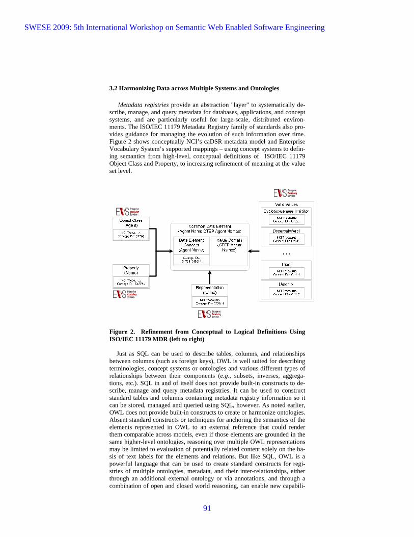
3.2 Harmonizing Data across Multiple Systems and Ontologies
Metadata registries provide an abstraction "layer" to systematically de-scribe, manage, and query metadata for databases, applications, and concept systems, and are particularly useful for large-scale, distributed environ-ments. The ISO/IEC 11179 Metadata Registry family of standards also pro-vides guidance for managing the evolution of such information over time. Figure 2 shows conceptually NCI’s caDSR metadata model and Enterprise Vocabulary System’s supported mappings – using concept systems to defin-ing semantics from high-level, conceptual definitions of ISO/IEC 11179 Object Class and Property, to increasing refinement of meaning at the value set level.
Figure 2. Refinement from Conceptual to Logical Definitions Using ISO/IEC 11179 MDR (left to right)
Just as SQL can be used to describe tables, columns, and relationships between columns (such as foreign keys), OWL is well suited for describing terminologies, concept systems or ontologies and various different types of relationships between their components (e.g., subsets, inverses, aggrega-tions, etc.). SQL in and of itself does not provide built-in constructs to de-scribe, manage and query metadata registries. It can be used to construct standard tables and columns containing metadata registry information so it can be stored, managed and queried using SQL, however. As noted earlier, OWL does not provide built-in constructs to create or harmonize ontologies. Absent standard constructs or techniques for anchoring the semantics of the elements represented in OWL to an external reference that could render them comparable across models, even if those elements are grounded in the same higher-level ontologies, reasoning over multiple OWL representations may be limited to evaluation of potentially related content solely on the ba-sis of text labels for the elements and relations. But like SQL, OWL is a powerful language that can be used to create standard constructs for regi-stries of multiple ontologies, metadata, and their inter-relationships, either through an additional external ontology or via annotations, and through a combination of open and closed world reasoning, can enable new capabili-
SWESE 2009: 5th International Workshop on Semantic Web Enabled Software Engineering
91

ties that make such registries invaluable to their users, particularly for ques-tion answering over large distributed repositories.
One recent effort employed OWL to evaluate the BRIDG Domain Analy-sis Model (DAM) a multi-agency effort to develop a shared view of the data, relationships, and processes which collectively define “protocol-driven research and its associated regulatory artifacts.” The first formal release of BRIDG, using the Unified Modeling Language (UML) [14] was published in June 2007 [5]. In late 2008, NCI commissioned a study to use the Ontol-ogy Definition Metamodel (ODM) [8] to translate the BRIDG DAM from UML to OWL in order to help identify potential problems with BRIDG as a data model. The absence of built-in constructs for comparative purposes re-sulted in a lot of manual effort to ensure that comparisons between versions of the model were apples-to-apples. The assignment of immutable identifi-ers and versions to the elements of the owl model emulate an ISO/IEC 11179 MDR approach.
The resulting analysis concluded that there were several flaws and ambi-guities in the BRIDG model, including problems with relationship names and types, and what was termed an "explosion of attributes in the mod-el...due to the creation of a new Common Data Element (CDE) when the concept is the same but the context of use is different." The report cites post-alAddress as an example: "This attribute occurs 8 times in the model, all with the same AD datatype expression, and all referencing a physical postal address of an entity but all with a slightly different definition." In this case, however, showing different variants could be considered a feature or strength of the BRIDG model rather than a "bug," depending on what pur-poses the model is intended to serve. A more general solution might be to have a single generic postalAddress class, with subclasses for different va-riants that are used by different groups and agencies. The new draft ISO/IEC 11179 (E3) metadata registry standard and XMDR prototype support just this kind of capability to document and manage the evolution of application and database-specific variants while at the same time showing their commo-nalities and translation requirements. If the semantics of each component of a particular variant are identical then they should be modeled as one object, but if they differ even slightly, it often is helpful to be able to distinguish and identify those subtle differences, as well as to note how one may be transformed to the other, with or without loss of information in one or both directions.
Whether we use OWL, UML, or other representation paradigms such as Entity-Relationship modeling, each of which can serve multiple purposes in the context we’ve described, we still need an additional level of abstraction for management of both data model and ontology information, along with the relationships between them in order to document, manage, and harmon-ize data and semantics from diverse systems particularly as they evolve over time.
4 ISO/IEC 11179 Metadata Registry Standard
The first edition of ISO/IEC 11179, which became a formal standard in
1994, established a discipline for standardization of data elements such as
SWESE 2009: 5th International Workshop on Semantic Web Enabled Software Engineering
92
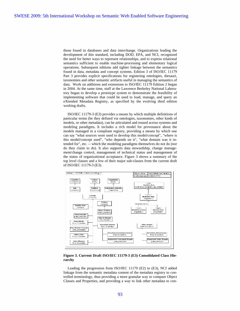
those found in databases and data interchange. Organizations leading the development of this standard, including DOD, EPA, and NCI, recognized the need for better ways to represent relationships, and to express relational semantics sufficient to enable machine-processing and elementary logical operations. Subsequent editions add tighter linkage between the semantics found in data, metadata and concept systems. Edition 3 of ISO/IEC 11179 Part 3 provides explicit specifications for registering ontologies, thesauri, taxonomies and other semantic artifacts useful in managing the semantics of data. Work on additions and extensions to ISO/IEC 11179 Edition 2 began in 2004. At the same time, staff at the Lawrence Berkeley National Labora-tory began to develop a prototype system to demonstrate the feasibility of implementing software that could be used to load, manage, and query an eXtended Metadata Registry, as specified by the evolving third edition working drafts.
ISO/IEC 11179-3 (E3) provides a means by which multiple definitions of particular terms (be they defined via ontologies, taxonomies, other kinds of models, or other metadata), can be articulated and reused across systems and modeling paradigms. It includes a rich model for provenance about the models managed in a compliant registry, providing a means by which one can say "what sources were used to develop this model/concept", "where is this model/concept used", "who depends on it", "what domain was it in-tended for", etc. -- which the modeling paradigms themselves do not do (nor do they claim to do). It also supports data stewardship, change manage-ment/change control, management of technical status and management of the status of organizational acceptance. Figure 3 shows a summary of the top level classes and a few of their major sub-classes from the current draft of ISO/IEC 11179-3 (E3).
Figure 3. Current Draft ISO/IEC 11179-3 (E3) Consolidated Class Hie-rarchy
Leading the progression from ISO/IEC 11179 (E2) to (E3), NCI added linkage from the semantic metadata content of the metadata registry to con-trolled terminology, thus providing a more granular way to compare Object Classes and Properties, and providing a way to link other metadata to con-
SWESE 2009: 5th International Workshop on Semantic Web Enabled Software Engineering
93
trolled terminology so researchers can explore/discover what might be simi-lar or related, to the data item of interest. An overview of the architecture, current implementation, including the use of OWL and UML models, and directions this work is taking at NCI as a part of the cancer Biomedical In-formatics Grid (caBIG) program is presented in [17].
5 OWL AND THE 11179 XMDR PROTOTYPE
UML models, OWL ontologies, and XML schemas each capture impor-tant, but not identical content useful for design and implementation of in-formation systems. The XMDR project demonstrated this at two levels for metadata registries. First, based on formative ISO/IEC 11179 (E3) specifi-cations, the XMDR was designed to capture and interrelate selected content of UML models, XML schemas, and OWL ontologies, as well as concept systems in terms of semantic relationships as well as traditional metadata. Second, UML models, XML schemas and OWL based technologies were used to implement the XMDR prototype.
In response to user needs for extensions to the ISO/IEC 11179 (E2) me-tamodel such as the extensions implemented in NCI’s caDSR, plus the need to test whether such extensions could be practically implemented and dep-loyed using real data and concept systems, the XMDR project developed several types of metadata registry extensions including:
1. standardized representation of logical and other types of relationships;
2. a metamodel framework to facilitate controlled and well-documented
management and evolution of terminologies, thesauri, concept systems and ontologies in the same way that data elements, value domains, and related types of information are managed in the ISO/IEC 11179 (E2) framework;
3. use of OWL to permit and facilitate reasoning based on logical inference. After reviewing a number of candidate languages and software packages,
LBNL implemented the XMDR prototype as a modular, open architecture system, which makes it relatively easy to substitute software modules for particular components (e.g., database system, reasoner).
Figure 4 shows the over-all modular component architecture of the
XMDR prototype, along with particular open source software used for its current components. In this schematic diagram, ovals or rounded boxes de-pict major components of the XMDR system, while rectangles represent da-ta, metadata, and indexes. Planned extensions are shown in shaded ovals. The XMDR Prototype used Poseidon and Protégé to create and edit UML and an OWL ontology that describes the XMDR metamodel. These specify how metadata is organized within the metadata registry store. The diagram also shows how content is transformed and loaded -- using LexGrid and cus-tom XSLT scripts to create standard "XMDR files." XMDR files are in-dexed using Jena and Pellet to create RDF files that are stored in a Postgres database, and then further processed using Lucene to create a text index. Human users (using web browsers) can create queries and display results us-ing a combination of JSP code and a standard REST interface. Other soft-
SWESE 2009: 5th International Workshop on Semantic Web Enabled Software Engineering
94
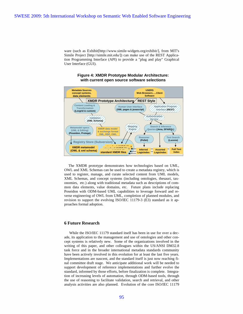
ware (such as Exhibit[http://www.simile-widgets.org/exhibit/], from MIT's Simile Project [http://simile.mit.edu/]) can make use of the REST Applica-tion Programming Interface (API) to provide a "plug and play" Graphical User Interface (GUI).
Figure 4: XMDR Prototype Modular Architecture:with current open source software selections
Registry Store (Subversion)
Search & Inference Queries (Jena, SPARQL)
XMDR metamodel(OWL & xml schema) Full Text
Index
XMDR Prototype Architecture REST Style
standard XMDR filesstandard XMDR files
standard XMDR filesstandard XMDR files
AssertedLogicIndex
InferredLogicIndex
Content Loading & Transformation
(Lexgrid & custom)
Human User Interface(XML pages & javascript)
Metadata Sources concept systems,data elements
USERSWeb Browsers…..Client
Software
Application Program Interface (REST)
Authentication ServiceValidation
(XML Schema)
MappingEngine
Reasoner(Pellet)
Text Search(Lucene)
Metamodel specs(UML & Editing)
(Poseidon, Protege)
XMDR data model & exchange format
XML, RDF, OWL
The XMDR prototype demonstrates how technologies based on UML,
OWL and XML Schemas can be used to create a metadata registry, which is used to register, manage, and curate selected content from UML models, XML Schemas, and concept systems (including ontologies, thesauri, tax-onomies, etc.) along with traditional metadata such as descriptions of com-mon data elements, value domains, etc. Future plans include replacing Poseidon with ODM-based UML capabilities to leverage forward and re-verse engineering of OWL from UML, completion of planned modules, and revision to support the evolving ISO/IEC 11179-3 (E3) standard as it ap-proaches formal adoption.
6 Future Research
While the ISO/IEC 11179 standard itself has been in use for over a dec-ade, its application to the management and use of ontologies and other con-cept systems is relatively new. Some of the organizations involved in the writing of this paper, and other colleagues within the US/ANSI DM32.8 task force and in the broader international metadata standards community have been actively involved in this evolution for at least the last five years. Implementations are nascent, and the standard itself is just now reaching fi-nal committee draft stage. We anticipate additional work will be needed to support development of reference implementations and further evolve the standard, informed by those efforts, before finalization is complete. Integra-tion of increasing levels of automation, through ODM-based tools, through the use of reasoning to facilitate validation, search and retrieval, and other analysis activities are also planned. Evolution of the core ISO/IEC 11179
SWESE 2009: 5th International Workshop on Semantic Web Enabled Software Engineering
95

ontology, potentially reflecting the availability of new features in OWL 2, is also on our roadmap.
7 Conclusion
UML, OWL, and ODM have been instrumental in enabling better ways of characterizing and documenting information models and knowledge but they only provide the basic representation language constructs required as a starting point. Our experiences with the BRIDG 2.0 domain analysis model, development of the new draft ISO/IEC 11179 (E3) Metadata Registry Stan-dard, and implementation of the Extended Metadata Registry (XMDR) Pro-totype System help illustrate the need to combine these technologies with those such as UML/ODM, OWL, and the Semantic Web with more tradi-tional metadata registry tools and procedures to begin to address some of the really difficult information interchange issues faced by large organizations today. Utilizing a combination of ontology and knowledge representation languages, linked with standard metamodels for describing data and metada-ta provide an unprecedented opportunity to leverage semantic web for knowledge mining and discovery of hidden links and improve their utility in data management.
Disclaimer
This article is based in part upon work supported by the Environmental Protection Agency, Department of Defense, National Cancer Institute, and the National Science Foundation under NSF Grant No. 0637122. Any opi-nions, findings, and conclusions or recommendations expressed in this ar-ticle are those of the authors and do not necessarily reflect the views of the sponsors.
References
1. Mike Dean and Guus Schreiber, eds., Sean Bechhofer, Frank van Harmelen, Jim Hendler, Ian Horrocks, Deborah L. McGuinness, Peter F. Patel-Schneider, and Lynn Andrea Stein. OWL Web Ontology Language 1.0 Reference, W3C Rec-ommendation, World Wide Web Consortium, Amsterdam, The Netherlands, 10 February 2004. Latest version is available at http://www.w3.org/TR/owl-ref/.
2. Tom Gruber (1993). "A translation approach to portable ontology specifications". In: Knowledge Acquisition. 5: 199
3. ISO/IEC 11179 – Metadata Registries - Part 3 (Edition 3), Available at http://metadata-stds.org/11179/index.html#A3.
4. ISO/IEC 19763, Information Technology – Metamodel Framework for Interope-rability (MFI), Available at http://metadata-standards.org/19763/index.html.
5. Christopher A. Welty and Elisa F. Kendall, eds. Ontology Definition Metamodel (ODM), Version 1.0 Specification, Object Management Group, Inc., Needham, MA, May 2009. Latest version is available at: http://www.omg.org/spec/ODM/1.0/.
6. http://gforge.nci.nih.gov/projects/bridg-model and 7. http://bridgmodel.org/ 8. https://gforge.nci.nih.gov/projects/bridgrev 9. http://informatics.mayo.edu/LexGrid/
SWESE 2009: 5th International Workshop on Semantic Web Enabled Software Engineering
96

10. http://XMDR.org/ 11. Peter A. Covitz , Frank Hartel, Carl Schaefer, Sherri De Coronado, Gilberto Fra-
goso, Himanso Sahni, Scott Gustafson and Kenneth H. Buetow, caCORE: A common infrastructure for cancer informatics, Bioinformatics, Vol. 19 no. 18 2003, pages 2404–2412
12. Komatsoulis, GA, Warzel, D.B, Hartel, F.W., Shanbhag, K, Chilukuri, R, Fra-goso, G., de Coronado, S, Reeves, D.M, Hadfield, J.G., Ludet, C., and Covitz, P. A. (2008) caCORE version 3; Implementation of a model driven service-oriented architecture for semantic interoperability. Journal of Bioinformatics, 41:1
13. caDSR http://ncicb.nci.nih.gov/NCICB/infrastructure/cacore_overview/cadsr and EVS http://bioportal.nci.nih.gov/ncbo/faces/index.xhtml statistics citation
14. EDR http://iaspub.epa.gov/sor_internet/registry/datareg/home/overview/home.do 15. Berners-Lee, T, http://www.w3.org/DesignIssues/RDFnot.html 16. Unified Modeling Language™ (UML®) Infrastructure and Superstructure Speci-
fications, Version 2.1.2, Object Management Group, Inc., Needham, MA, No-vember 2007. Latest versions of this and related UML specification components is available at: http://www.omg.org/spec/UML/2.1.2/.
17. Alejandra González Beltrán, Anthony Finkelstein, J. Max Wilkinson, and Jeff Kramer (forthcoming). “Domain Concept-Based Queries for Cancer Research Data Sources”.
SWESE 2009: 5th International Workshop on Semantic Web Enabled Software Engineering
97


