Istruzioni AP3 Modulo e pomolo - cisa.com · orifi cios, en el lado liso (no moleteado). Inserte...
2
IT ISTRUZIONI DI MONTAGGIO PER AP3 S MODULO, DOPPIO FRIZIONATO EN INSTRUCTION SHEET FOR THE AP3 S MODULO DOUBLE CYLINDER WITH CLUTCH FR INSTRUCTIONS DE MONTAGE POUR AP3 S MODULO, DOUBLE À FRICTION ES INSTRUCCIONES DE MONTAJE PARA AP3 S MÓDULO DOBLE CON EMBRAGUE RU ИНСТРУКЦИЯ ПО МОНТАЖУ ДВОЙНОГО ФРИКЦИОННОГО ЦИЛИНДРА AP3 S MODULO NB. Il numero e le misure dei gruppi estensioni sono indicativi e dipendono dalla dimensione finale del cilindro. CISA consiglia comunque di non accoppiare più di 3 gruppi estensioni per lato al fine di mantenere invariate le caratteristiche di resistenza del cilindro. NOTE: the quantity and measurements of the extended units given in this sheet are purely indicative and depend on the cylinder final dimension. CISA recommends not to add more than 3 extended bolt units per each side in order to keep the cylinder resistance unchanged. NB. Le nombre et les dimensions des groupes extensions sont indicatifs et dépendent de la dimension finale du cylindre. CISA conseille néanmoins de ne pas accoupler plus de 3 groupes extensions par côté afin de garder les caractéristiques de résistance du cylindre inchangées. NOTA: El número y las medidas de los grupos de extensiones son indicativos y dependen de las dimensiones finales del cilindro. De todos modos, CISA recomienda no acoplar más de tres grupos de extensiones por lado, con el objetivo de mantener invariadas las características de resistencia del cilindro. Примечание: количество и размеры удлинитель- ных узлов являются приблизительными и зависят от конечного размера цилиндра. CISA рекомендует не соединять более 3 удлинительных узлов для каждой стороны с целью поддержания неизмен- ными характеристики сопротивления и прочности цилиндра. ATTREZZI TOOLS OUTILS HERRAMIENTAS ИНСТРУМЕНТЫ - giravite a taglio Ø4x0.8, - punzone Ø3x125, - pinzetta a molla con punte piatte arrotondate L. 115 mm, - mazzuola con tasselli in plastica Ø28x250 gr - base di appoggio per il cilindro (in dotazione) - Screwdriver Ø4x0.8 - punch Ø3x125 - flat round tip tweezers L. 115 mm - mallet with plastic tips Ø28x250 gr - cylinder support (supplied as standard) - tournevis à fente Ø4x0.8, - poinçon Ø3x125, - pincette à ressort à pointes plates arrondies L. 115 mm, - maillet à embouts plastique Ø28x250 g - base d’appui pour le cylindre (fournie) - destornillador plano Ø4x0,8 - punzón Ø3x125 - pinza de muelle con puntas planas redondeadas L. 115 mm - mazo con tacos de plástico Ø28x250 g - base de apoyo para el cilindro (suministrada) - отвертка Ø4x0.8, - кернер Ø3x125, - пружинные щипцы с плоскими закругленными концами L. 115 мм, - киянка с пластмассовыми бойками Ø28x250 г - опорная подставка для цилиндра (в комплекте поставки) Ref. COMPONENTI COMPONENTS COMPOSANTS COMPONENTES КОМПОНЕНТЫ 1 Coppia moduli con chiavi Pair of modules with key Paire de modules avec clés Par de módulos con llaves Пара модулей с ключами 1 1 6 6 4 3 2 2 5 7 7 2 2 Gruppo/i estensioni (per lati >35) Extended bolt unit/s (for sides >35) Groupe/s extensions (pour côtés >35) Grupo/s de extensiones (para lados >35) Удлинительный/ые узел/лы (для сторон >35) 3 Gruppo innesti (vedi particolare A) Coupling units (see detail A) Groupe emboîtements (voir détail A) Grupo de empalmes (véase el componente A) Соединительный узел (см. деталь A) 4 Camma Cam Came Leva Кулачок 5 Gruppo SIGILLO Snap resistant device Groupe SIGILLO Grupo SIGILLO Узел СЕРДЕЧНИК 6 Spine di fissaggio Fixing pins Goupilles de fixation Clavijas de fijación Крепежные штифты 7 Vite assemblaggio gruppo estensioni Fixing screw for extended bolt units Vis d’assemblage groupe extensions Tornillo de montaje grupo de extensiones Винты для соединения удлинительных узлов Note Notes Notes Notas Примечания T.1 1 Rilevare lo spessore della porta e definire la lunghezza lato A e B del cilindro Measure the door thickness and define the length of side A and side B of the cylinder. Relever l’épaisseur de la porte et définir la longueur côté A et B du cylindre. Mida el espesor de la puerta y defina la longitud de los lados A y B del cilindro. Определить толщину двери и длину сторон A и B цилиндра. T.2 2 Accoppiare il 1° modulo con 1° gruppo estensioni. Inserire ed avvitare la 1° vite di fissaggio nel gruppo estensioni. Per modulo 35 mm inserire prolunga “B”. Couple the 1st module with the 1st extended bolt unit. Insert the 1st fixing screw and tighten it in the extended bolt unit. For a 35 mm module insert the extended bolt unit “B”. Accoupler le 1er module avec le 1er groupe extensions. Introduire et visser la 1e vis de fixation dans le groupe extensions. Pour le module 35 mm introduire la rallonge « B ». Acople el 1° módulo con el 1° grupo de extensiones. Inserte y enrosque el 1° tornillo de fijación en el grupo de extensiones. Para el módulo 35 mm, inserte la alargadera B. Соединить 1° модуль с 1° удлинительным узлом. Вставить в удлинительный узел и затянуть 1° крепежный винт . Для модуля на 35 мм вставить удлинитель “B”. 3 Accoppiare il 2° modulo con il 2° gruppo estensioni. Inserire ed avvitare la 2° vite di fissaggio nel gruppo estensioni.Per modulo 35 mm inserire prolunga “B”. Couple the 2nd module with the 2nd extended bolt unit. Insert and tighten the 2nd fixing screw to the extended bolt unit. For a 35 mm module insert the extended bolt unit “B”. Accoupler le 2e module avec le 2e groupe extensions. Introduire et visser la 2e vis de fixation dans le groupe extensions. Pour le module 35 mm introduire la rallonge « B ». Acople el 2° módulo con el 2° grupo de extensiones. Inserte y enrosque el 2° tornillo de fijación en el grupo de extensiones. Para el módulo 35 mm, inserte la alargadera B. Соединить 2° модуль со 2° удлинительным узлом. Вставить и завинтить 2° крепежный винт в удлинительном узле. Для модуля на 35 мм использовать удлинитель “B”. 4 Togliere nastro dalla confezione del gruppo SIGILLO ed allineare i fori giunto- lamelle del gruppo. Se necessario usare il punzone. Remove the tape from the Snap Resistant unit package and align the holes in the binder and in the core laminations. Use the punch if necessary. Enlever le ruban de l’emballage du groupe SIGILLO et aligner les trous joint/lamelles du groupe SIGILLO. Si nécessaire utiliser le poinçon. Quite la cinta del grupo SIGILLO y alinee los orificios junta-laminillas. Si es necesario, utilice el punzón. Удалить ленту с упаковки узла СЕРДЕЧНИКА и отцентровать отверстия соединения и пластин этого узла. При необходимости пользоваться кернером. 5 Accoppiare il gruppo SIGILLO con il 1° gruppo modulo+estensioni. Couple the Snap resistant device with the 1st module/extended built unit. Accoupler le groupe SIGILLO avec le 1er groupe module+extensions. Acople el grupo SIGILLO con el 1° grupo módulo + extensiones. Соединить узел СЕРДЕЧНИКА с 1° узлом модуль+удлинения. 6 Accoppiare il gruppo innesti sull’ estensione posizionando l’aletta innesto verso il basso e di seguito la camma sul gruppo innesti. Couple the coupling unit with the extended bolt unit positioning the coupling tongue towards the bottom and then the cam on the coupling units. Accoupler le groupe emboîtements sur l’extension en plaçant l’ailette d’emboîtement vers le bas et ensuite la came sur le groupe emboîtements. Acople el grupo de empalmes en la extensión ―colocando la aleta de empalme hacia abajo― y, a continuación, acople la leva en el grupo de empalmes. Прикрепить соединительный узел к удлинению, повернув язычок соединения книзу , и затем приставить кулачок с другой стороны соединительного узла. 7 Accoppiare il 2° gruppo modulo+estensioni con il 1° gruppo modulo+estensioni+SIGILLO avendo cura di mettere in fase innesti e camma. Couple the 2nd module/extended bolt unit with the 1st module/extended bolt unit/ Snap resistant device taking care that the couplings and the cam are perfectly aligned. Accoupler le 2e groupe module+extensions avec le 1er groupe module+extensions+SIGILLO en ayant soin de mettre en phase les emboîtements et les cames. Acople el 2° grupo módulo + extensiones con el 1° grupo módulo + extensiones + SIGILLO, alineando los empalmes y la leva. Соединить 2° узел модуль+удлинения с 1° узлом модуль+удлинения +СЕРДЕЧНИК, проконтролировав центровку соединений и кулачка. 8 Posizionare il cilindro col lato camma sporgente verso l’alto. Pre-inserire le spine di bloccaggio gruppo SIGILLO nei rispettivi fori dal lato liscio non zigrinato. Inserire le spine utilizzando il mazzuolo (se necessario usare il punzone per evitare sporgenze dalla sagoma del cilindro). Position the cylinder with the cam side protruded towards the top. Pre/position the fixing pins of the Snap resistant device in the holes on the smooth side.Insert the pins with the mallet (also use the punch if necessary, to avoid any projections from the cylinder profile). Placer le cylindre avec le côté came qui dépasse vers le haut. Pré-introduire les goupilles de blocage groupe SIGILLO dans les trous respectifs du côté lisse non moleté. Introduire les goupilles à l’aide du maillet (si nécessaire utiliser le poinçon pour éviter qu'elles ne dépassent du gabarit du cylindre). Coloque el cilindro con el lado de la leva sobresaliente hacia arriba. Introduzca manualmente las clavijas de bloqueo del grupo SIGILLO en los respectivos orificios, en el lado liso (no moleteado). Inserte completamente las clavijas utilizando el mazo (si es necesario, utilice el punzón para evitar que sobresalgan del perfil del cilindro). Разместить цилиндр с выступающей кверху стороной кулачка. Приставить блокировочные штифты узла СЕРДЕЧНИКА к соответствующим отверстиям с гладкой стороны. Ввести штифты при помощи киянки (при необходимости пользоваться кернером во избежание выступов за профиль цилиндра). T.3 9 Eseguire prova funzionale. Carry out a functional test. Effectuer l’essai fonctionnel. Realice una prueba funcional. Провести проверку работоспособности. 10 Ripetere prova funzionale. Repeat the functional test. Répéter l’essai fonctionnel. Repita la prueba funcional. Повторить проверку работоспособности. 11 Ruotare la 1^ chiave di circa 30-45°, inserire una 2^ chiave dal lato opposto, ruotare controllando che la camma venga agganciata ottenendo la contemporanea rotazione dei due lati del cilindro. Rotate the first key through approximately 30-45°, insert a second key on the opposite side, rotate it making sure that the cam is hooked and both sides of the cylinder rotate at the same time. Tourner la 1e clé d’environ 30-45°, introduire une 2e clé du côté opposé, tourner en contrôlant que la came est accrochée obtenant ainsi la rotation simultanée des deux côtés du cylindre. Gire la 1ª llave aproximadamente 30-45°, inserte una 2ª llave en el lado opuesto y gírela, verificando el enganche de la leva y la simultánea rotación de los dos lados del cilindro. Повернуть 1^ ключ на приблизительно 30- 45°, вставить 2^ ключ с противоположной стороны и поворачивать, контролируя, чтобы кулачок произвел сцепление с одновременным вращением обеих сторон цилиндра. N.B. Prima di montare i gruppi innesti occorre controllare che il bottone sia correttamente posizionato nella sua sede, eventualmente riposizionarlo con la pinzetta. NOTE. Before installing the coupling units make sure that the button is positioned correctly in its seat, and position it correctly with the tweezers if necessary N.B. : Avant de monter les groupes emboîtements il faut contrôler que le bouton à ressort est correctement placé dans son logement, éventuellement le repositionner avec la pincette. NOTA: Antes de colocar los grupos de empalmes, es necesario verificar que el botón esté correcta- mente colocado en su alojamiento; si es necesario, colóquelo con la pinza. Примечание: до установки соединительных узлов необходимо проверить, чтобы пружинный штифт находился в своем гнезде, при необходимости отрегулировать его положение щипцами. T.1 LUNGHEZZA CILINDRO CYLINDER LENGTH LONGUEUR CYLINDRE LONGITUD DEL CILINDRO ДЛИНА ЦИЛИНДРА A B Max 3 mm Max 3 mm 1 T.2 MONTAGGIO INSTALLATION MONTAGE MONTAJE МОНТАЖ 2 B 3 4 5 A 6 7 8 T.3 VERIFICHE FINALI FINAL CHECKS VÉRIFICATIONS FINALES CONTROLES FINALES КОНЕЧНАЯ ПРОВЕРКА 9 10 11 I prodotti qui evidenziati sono dotati di tutte le caratteristiche indicate nella descrizione tecnica dei cataloghi CISA S.p.A. e sono consigliati solamente per gli scopi ivi precisati. La società CISA S.p.A. non garantisce nessuna prestazione o caratteristica tecnica che non sia indicata su queste istruzioni; NON possono essere apportate al prodotto modifiche diverse da quanto espressamente indicato da CISA pena il decadimento degli obblighi di garanzia previsti dalla legge e delle eventuali certificazioni di conformità di prodotto. Per particolari esigenze di sicurezza si invita l’utente a rivolgersi al rivenditore o installatore di questi prodotti ovvero direttamente alla CISA, i quali potranno meglio consigliare il modello più appropriato alle specifiche esigenze del cliente. The products described in this document display all the characteristics featured in the technical catalogues issued by CISA S.p.A. and should only be used for their design purposes. The manufacturer CISA S.p.A. will not guarantee any product performance or technical feature not specified in these instructions; NO product modifications different from those expressly described by CISA may be introduced, under penalty of loss of the guarantee rights provided for by law and by any product compliance certification. For special security requirements, the users should contact their product dealer or installer or directly the manufacturer CISA, who will be able to best advise on the most suitable models according to customer needs. Les produits cités ici sont munis de toutes les caractéristiques indiquées dans la description technique des catalogues CISA S.p.A. et sont conseillés uniquement pour les utilisations qui y sont spécifiées. La société CISA S.p.A. ne garantit aucune prestation ou caractéristique technique qui n’est pas indiquée dans ces instructions ; AUCUNE modification ne peut être effectuée sur le produit autre que ce qui est expressément indiqué par CISA sous peine d’annulation de la garantie prévue par la loi et des éventuelles certifications de conformité du produit. En cas d’exigences de sécurité particulières, nous invitons l’utilisateur à s’adresser au revendeur ou à l’installateur de ces produits ou bien directement à CISA, afin de recevoir les meilleurs conseils au sujet du modèle le plus approprié aux exigences spécifiques du client. Los productos aquí mencionados están dotados de todas las características indicadas en la descripción técnica de los catálogos de CISA S. p. A., y son recomendados exclusivamente para las aplicaciones allí señaladas. La sociedad CISA S. p. A. no garantiza ninguna prestación o característica técnica que no esté indicada en estas instrucciones. No está permitido realizar modificaciones en el producto diferentes a las indicadas expresamente por CISA, bajo pena de caducidad de las obligaciones de garantía previstas por la ley, así como de las eventuales certificaciones de conformidad del producto. Por particulares exigencias de seguridad, se invita al usuario a dirigirse al revendedor o instalador de dichos productos, o directamente a CISA, quienes podrán aconsejarle el modelo más apropiado para sus exigencias. Представленные здесь изделия обладают всеми характеристиками, указанными в техническом описании каталогов фирмы CISA Spa, и рекомендуются только для описанного там применения. Любое применение или технические характеристики, отличающиеся от указанных в данной инструкции, не гарантируются компанией CISA S.p.A.; изделия не должны быть подвержены каким-либо модицификациям, отличающимся от конкретно указанных компанией CISA, под страхом утраты предусмотренной законом гарантии и сертификатов соответствия продукта. В случае особых требований безопасности просим пользователя обращаться в представительство или к специалисту по установке данных изделий, а также непосредственно в компанию CISA, которые смогут порекомендовать наиболее подходящую модель для специфических нужд клиента.
Transcript of Istruzioni AP3 Modulo e pomolo - cisa.com · orifi cios, en el lado liso (no moleteado). Inserte...

IT ISTRUZIONI DI MONTAGGIO PER AP3 S MODULO, DOPPIO FRIZIONATO
EN INSTRUCTION SHEET FOR THE AP3 S MODULO DOUBLE CYLINDER WITH CLUTCH
FR INSTRUCTIONS DE MONTAGE POUR AP3 S MODULO, DOUBLE À FRICTION
ES INSTRUCCIONES DE MONTAJE PARA AP3 S MÓDULO DOBLE CON EMBRAGUE
RUИНСТРУКЦИЯ ПО МОНТАЖУ ДВОЙНОГО ФРИКЦИОННОГО ЦИЛИНДРА AP3 S MODULO
NB. Il numero e le misure dei gruppi estensioni sono indicativi e dipendono dalla dimensione fi nale del cilindro. CISA consiglia comunque di non accoppiare più di 3 gruppi estensioni per lato al fi ne di mantenere invariate le caratteristiche di resistenza del cilindro.
NOTE: the quantity and measurements of the extended units given in this sheet are purely indicative and depend on the cylinder fi nal dimension. CISA recommends not to add more than 3 extended bolt units per each side in order to keep the cylinder resistance unchanged.
NB. Le nombre et les dimensions des groupes extensions sont indicatifs et dépendent de la dimension fi nale du cylindre. CISA conseille néanmoins de ne pas accoupler plus de 3 groupes extensions par côté afi n de garder les caractéristiques de résistance du cylindre inchangées.
NOTA: El número y las medidas de los grupos de extensiones son indicativos y dependen de las dimensiones fi nales del cilindro. De todos modos, CISA recomienda no acoplar más de tres grupos de extensiones por lado, con el objetivo de mantener invariadas las características de resistencia del cilindro.
Примечание: количество и размеры удлинитель-ных узлов являются приблизительными и зависят от конечного размера цилиндра. CISA рекомендует не соединять более 3 удлинительных узлов для каждой стороны с целью поддержания неизмен-ными характеристики сопротивления и прочности цилиндра.
ATTREZZI TOOLS OUTILS HERRAMIENTAS ИНСТРУМЕНТЫ- giravite a taglio Ø4x0.8, - punzone Ø3x125, - pinzetta a molla con punte piatte arrotondate L.
115 mm, - mazzuola con tasselli in plastica Ø28x250 gr- base di appoggio per il cilindro (in dotazione)
- Screwdriver Ø4x0.8- punch Ø3x125- fl at round tip tweezers L. 115 mm- mallet with plastic tips Ø28x250 gr- cylinder support (supplied as standard)
- tournevis à fente Ø4x0.8,- poinçon Ø3x125,- pincette à ressort à pointes plates arrondies L.
115 mm,- maillet à embouts plastique Ø28x250 g- base d’appui pour le cylindre (fournie)
- destornillador plano Ø4x0,8- punzón Ø3x125- pinza de muelle con puntas planas redondeadas
L. 115 mm- mazo con tacos de plástico Ø28x250 g- base de apoyo para el cilindro (suministrada)
- отвертка Ø4x0.8,- кернер Ø3x125,- пружинные щипцы с плоскими закругленными концами L. 115 мм,
- киянка с пластмассовыми бойками Ø28x250 г- опорная подставка для цилиндра (в комплекте поставки)
Ref. COMPONENTI COMPONENTS COMPOSANTS COMPONENTES КОМПОНЕНТЫ
1
Coppia moduli con chiaviPair of modules with keyPaire de modules avec clésPar de módulos con llavesПара модулей с ключами
1
1
6
6
43
22
5
7
72
2
Gruppo/i estensioni (per lati >35)Extended bolt unit/s (for sides >35)Groupe/s extensions (pour côtés >35)Grupo/s de extensiones (para lados >35)Удлинительный/ые узел/лы (для сторон >35)
3
Gruppo innesti (vedi particolare A)Coupling units (see detail A)Groupe emboîtements (voir détail A) Grupo de empalmes (véase el componente A)Соединительный узел (см. деталь A)
4
CammaCamCameLevaКулачок
5
Gruppo SIGILLOSnap resistant deviceGroupe SIGILLOGrupo SIGILLOУзел СЕРДЕЧНИК
6
Spine di fi ssaggioFixing pinsGoupilles de fi xationClavijas de fi jaciónКрепежные штифты
7
Vite assemblaggio gruppo estensioniFixing screw for extended bolt unitsVis d’assemblage groupe extensionsTornillo de montaje grupo de extensionesВинты для соединения удлинительных узлов
Note Notes Notes Notas Примечания
T.1 1 Rilevare lo spessore della porta e defi nire la lunghezza lato A e B del cilindro
Measure the door thickness and defi ne the length of side A and side B of the cylinder.
Relever l’épaisseur de la porte et défi nir la longueur côté A et B du cylindre.
Mida el espesor de la puerta y defi na la longitud de los lados A y B del cilindro.
Определить толщину двери и длину сторон A и B цилиндра.
T.2
2Accoppiare il 1° modulo con 1° gruppo estensioni. Inserire ed avvitare la 1° vite di fi ssaggio nel gruppo estensioni. Per modulo 35 mm inserire prolunga “B”.
Couple the 1st module with the 1st extended bolt unit. Insert the 1st fi xing screw and tighten it in the extended bolt unit. For a 35 mm module insert the extended bolt unit “B”.
Accoupler le 1er module avec le 1er groupe extensions. Introduire et visser la 1e vis de fi xation dans le groupe extensions. Pour le module 35 mm introduire la rallonge « B ».
Acople el 1° módulo con el 1° grupo de extensiones. Inserte y enrosque el 1° tornillo de fi jación en el grupo de extensiones. Para el módulo 35 mm, inserte la alargadera B.
Соединить 1° модуль с 1° удлинительным узлом. Вставить в удлинительный узел и затянуть 1° крепежный винт. Для модуля на 35 мм вставить удлинитель “B”.
3Accoppiare il 2° modulo con il 2° gruppo estensioni. Inserire ed avvitare la 2° vite di fi ssaggio nel gruppo estensioni.Per modulo 35 mm inserire prolunga “B”.
Couple the 2nd module with the 2nd extended bolt unit. Insert and tighten the 2nd fi xing screw to the extended bolt unit. For a 35 mm module insert the extended bolt unit “B”.
Accoupler le 2e module avec le 2e groupe extensions. Introduire et visser la 2e vis de fi xation dans le groupe extensions. Pour le module 35 mm introduire la rallonge « B ».
Acople el 2° módulo con el 2° grupo de extensiones. Inserte y enrosque el 2° tornillo de fi jación en el grupo de extensiones. Para el módulo 35 mm, inserte la alargadera B.
Соединить 2° модуль со 2° удлинительным узлом. Вставить и завинтить 2° крепежный винт в удлинительном узле. Для модуля на 35 мм использовать удлинитель “B”.
4Togliere nastro dalla confezione del gruppo SIGILLO ed allineare i fori giunto-lamelle del gruppo. Se necessario usare il punzone.
Remove the tape from the Snap Resistant unit package and align the holes in the binder and in the core laminations. Use the punch if necessary.
Enlever le ruban de l’emballage du groupe SIGILLO et aligner les trous joint/lamelles du groupe SIGILLO. Si nécessaire utiliser le poinçon.
Quite la cinta del grupo SIGILLO y alinee los orifi cios junta-laminillas. Si es necesario, utilice el punzón.
Удалить ленту с упаковки узла СЕРДЕЧНИКА и отцентровать отверстия соединения и пластин этого узла. При необходимости пользоваться кернером.
5 Accoppiare il gruppo SIGILLO con il 1° gruppo modulo+estensioni.
Couple the Snap resistant device with the 1st module/extended built unit.
Accoupler le groupe SIGILLO avec le 1er groupe module+extensions.
Acople el grupo SIGILLO con el 1° grupo módulo + extensiones.
Соединить узел СЕРДЕЧНИКА с 1° узлом модуль+удлинения.
6Accoppiare il gruppo innesti sull’ estensione posizionando l’aletta innesto verso il basso e di seguito la camma sul gruppo innesti.
Couple the coupling unit with the extended bolt unit positioning the coupling tongue towards the bottom and then the cam on the coupling units.
Accoupler le groupe emboîtements sur l’extension en plaçant l’ailette d’emboîtement vers le bas et ensuite la came sur le groupe emboîtements.
Acople el grupo de empalmes en la extensión ―colocando la aleta de empalme hacia abajo― y, a continuación, acople la leva en el grupo de empalmes.
Прикрепить соединительный узел к удлинению, повернув язычок соединения книзу, и затем приставить кулачок с другой стороны соединительного узла.
7Accoppiare il 2° gruppo modulo+estensioni con il 1° gruppo modulo+estensioni+SIGILLO avendo cura di mettere in fase innesti e camma.
Couple the 2nd module/extended bolt unit with the 1st module/extended bolt unit/Snap resistant device taking care that the couplings and the cam are perfectly aligned.
Accoupler le 2e groupe module+extensions avec le 1er groupe module+extensions+SIGILLO en ayant soin de mettre en phase les emboîtements et les cames.
Acople el 2° grupo módulo + extensiones con el 1° grupo módulo + extensiones + SIGILLO, alineando los empalmes y la leva.
Соединить 2° узел модуль+удлинения с 1° узлом модуль+удлинения +СЕРДЕЧНИК, проконтролировав центровку соединений и кулачка.
8
Posizionare il cilindro col lato camma sporgente verso l’alto. Pre-inserire le spine di bloccaggio gruppo SIGILLO nei rispettivi fori dal lato liscio non zigrinato.Inserire le spine utilizzando il mazzuolo (se necessario usare il punzone per evitare sporgenze dalla sagoma del cilindro).
Position the cylinder with the cam side protruded towards the top. Pre/position the fi xing pins of the Snap resistant device in the holes on the smooth side.Insert the pins with the mallet (also use the punch if necessary, to avoid any projections from the cylinder profi le).
Placer le cylindre avec le côté came qui dépasse vers le haut. Pré-introduire les goupilles de blocage groupe SIGILLO dans les trous respectifs du côté lisse non moleté. Introduire les goupilles à l’aide du maillet (si nécessaire utiliser le poinçon pour éviter qu'elles ne dépassent du gabarit du cylindre).
Coloque el cilindro con el lado de la leva sobresaliente hacia arriba. Introduzca manualmente las clavijas de bloqueo del grupo SIGILLO en los respectivos orifi cios, en el lado liso (no moleteado). Inserte completamente las clavijas utilizando el mazo (si es necesario, utilice el punzón para evitar que sobresalgan del perfi l del cilindro).
Разместить цилиндр с выступающей кверху стороной кулачка. Приставить блокировочные штифты узла СЕРДЕЧНИКА к соответствующим отверстиям с гладкой стороны. Ввести штифты при помощи киянки (при необходимости пользоваться кернером во избежание выступов за профиль цилиндра).
T.3
9 Eseguire prova funzionale. Carry out a functional test. Effectuer l’essai fonctionnel. Realice una prueba funcional. Провести проверку работоспособности.
10 Ripetere prova funzionale. Repeat the functional test. Répéter l’essai fonctionnel. Repita la prueba funcional. Повторить проверку работоспособности.
11Ruotare la 1^ chiave di circa 30-45°, inserire una 2^ chiave dal lato opposto, ruotare controllando che la camma venga agganciata ottenendo la contemporanea rotazione dei due lati del cilindro.
Rotate the fi rst key through approximately 30-45°, insert a second key on the opposite side, rotate it making sure that the cam is hooked and both sides of the cylinder rotate at the same time.
Tourner la 1e clé d’environ 30-45°, introduire une 2e clé du côté opposé, tourner en contrôlant que la came est accrochée obtenant ainsi la rotation simultanée des deux côtés du cylindre.
Gire la 1ª llave aproximadamente 30-45°, inserte una 2ª llave en el lado opuesto y gírela, verifi cando el enganche de la leva y la simultánea rotación de los dos lados del cilindro.
Повернуть 1^ ключ на приблизительно 30-45°, вставить 2^ ключ с противоположной стороны и поворачивать, контролируя, чтобы кулачок произвел сцепление с одновременным вращением обеих сторон цилиндра.
N.B. Prima di montare i gruppi innesti occorre controllare che il bottone sia correttamente posizionato nella sua sede, eventualmente riposizionarlo con la pinzetta.
NOTE. Before installing the coupling units make sure that the button is positioned correctly in its seat, and position it correctly with the tweezers if necessary
N.B. : Avant de monter les groupes emboîtements il faut contrôler que le bouton à ressort est correctement placé dans son logement, éventuellement le repositionner avec la pincette.
NOTA: Antes de colocar los grupos de empalmes, es necesario verifi car que el botón esté correcta-mente colocado en su alojamiento; si es necesario, colóquelo con la pinza.
Примечание: до установки соединительных узлов необходимо проверить, чтобы пружинный штифт находился в своем гнезде, при необходимости отрегулировать его положение щипцами.
T.1 LUNGHEZZA CILINDRO
CYLINDER LENGTH
LONGUEUR CYLINDRE
LONGITUD DEL CILINDRO
ДЛИНА ЦИЛИНДРА
A B
Max 3 mm Max 3 mm
1
T.2 MONTAGGIO INSTALLATION MONTAGE MONTAJE МОНТАЖ
2B
3
4
5
A
6
7
8
T.3 VERIFICHE FINALI
FINAL CHECKS
VÉRIFICATIONS FINALES
CONTROLES FINALES
КОНЕЧНАЯ ПРОВЕРКА
9
10
11
I prodotti qui evidenziati sono dotati di tutte le caratteristiche indicate nella descrizione tecnica dei cataloghi CISA S.p.A. e sono consigliati solamente per gli scopi ivi precisati. La società CISA S.p.A. non garantisce nessuna prestazione o caratteristica tecnica che non sia indicata su queste istruzioni; NON possono essere apportate al prodotto modifi che diverse da quanto espressamente indicato da CISA pena il decadimento degli obblighi di garanzia previsti dalla legge e delle eventuali certifi cazioni di conformità di prodotto. Per particolari esigenze di sicurezza si invita l’utente a rivolgersi al rivenditore o installatore di questi prodotti ovvero direttamente alla CISA, i quali potranno meglio consigliare il modello più appropriato alle specifi che esigenze del cliente.
The products described in this document display all the characteristics featured in the technical catalogues issued by CISA S.p.A. and should only be used for their design purposes. The manufacturer CISA S.p.A. will not guarantee any product performance or technical feature not specifi ed in these instructions; NO product modifi cations different from those expressly described by CISA may be introduced, under penalty of loss of the guarantee rights provided for by law and by any product compliance certifi cation. For special security requirements, the users should contact their product dealer or installer or directly the manufacturer CISA, who will be able to best advise on the most suitable models according to customer needs.
Les produits cités ici sont munis de toutes les caractéristiques indiquées dans la description technique des catalogues CISA S.p.A. et sont conseillés uniquement pour les utilisations qui y sont spécifi ées. La société CISA S.p.A. ne garantit aucune prestation ou caractéristique technique qui n’est pas indiquée dans ces instructions ; AUCUNE modifi cation ne peut être effectuée sur le produit autre que ce qui est expressément indiqué par CISA sous peine d’annulation de la garantie prévue par la loi et des éventuelles certifi cations de conformité du produit. En cas d’exigences de sécurité particulières, nous invitons l’utilisateur à s’adresser au revendeur ou à l’installateur de ces produits ou bien directement à CISA, afi n de recevoir les meilleurs conseils au sujet du modèle le plus approprié aux exigences spécifi ques du client.
Los productos aquí mencionados están dotados de todas las características indicadas en la descripción técnica de los catálogos de CISA S. p. A., y son recomendados exclusivamente para las aplicaciones allí señaladas. La sociedad CISA S. p. A. no garantiza ninguna prestación o característica técnica que no esté indicada en estas instrucciones. No está permitido realizar modifi caciones en el producto diferentes a las indicadas expresamente por CISA, bajo pena de caducidad de las obligaciones de garantía previstas por la ley, así como de las eventuales certifi caciones de conformidad del producto. Por particulares exigencias de seguridad, se invita al usuario a dirigirse al revendedor o instalador de dichos productos, o directamente a CISA, quienes podrán aconsejarle el modelo más apropiado para sus exigencias.
Представленные здесь изделия обладают всеми характеристиками, указанными в техническом описании каталогов фирмы CISA Spa, и рекомендуются только для описанного там применения. Любое применение или технические характеристики, отличающиеся от указанных в данной инструкции, не гарантируются компанией CISA S.p.A.; изделия не должны быть подвержены каким-либо модицификациям, отличающимся от конкретно указанных компанией CISA, под страхом утраты предусмотренной законом гарантии и сертификатов соответствия продукта. В случае особых требований безопасности просим пользователя обращаться в представительство или к специалисту по установке данных изделий, а также непосредственно в компанию CISA, которые смогут порекомендовать наиболее подходящую модель для специфических нужд клиента.
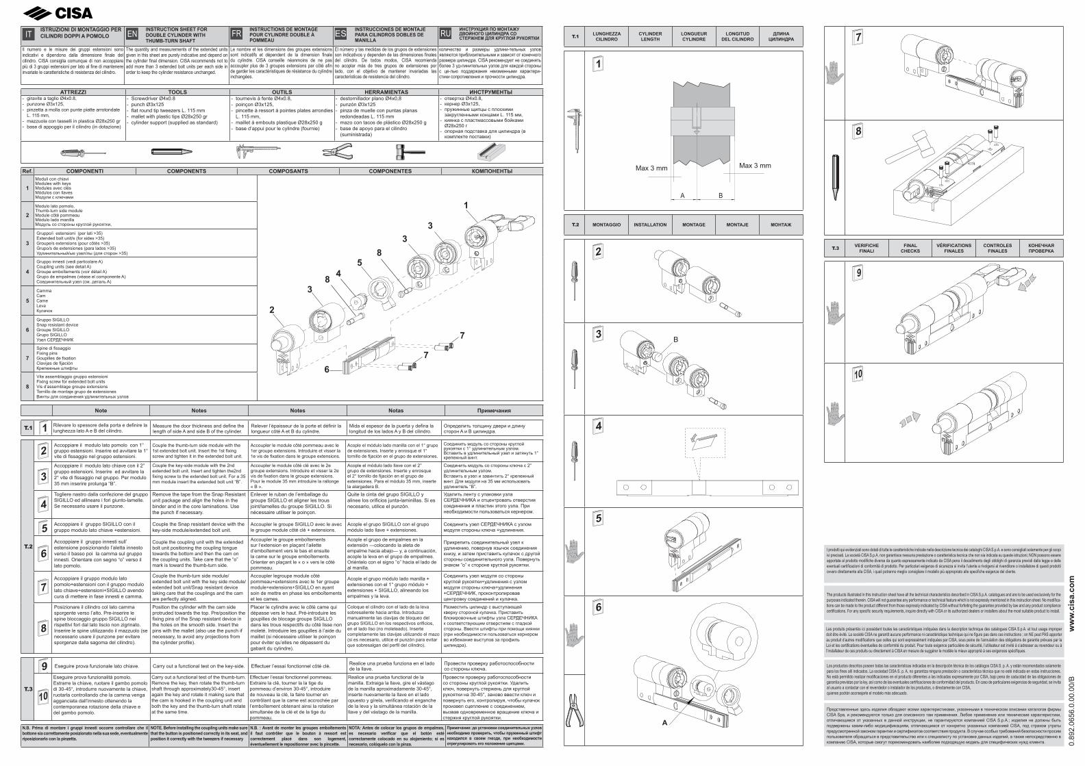
IT ISTRUZIONI DI MONTAGGIO PER CILINDRI DOPPI A POMOLO EN INSTRUCTION SHEET FOR
DOUBLE CYLINDER WITH THUMB-TURN SHAFT
FR INSTRUCTIONS DE MONTAGE POUR CYLINDRE DOUBLE À POMMEAU
ES INSTRUCCIONES DE MONTAJE PARA CILINDROS DOBLES DE MANILLA
RU ИНСТРУКЦИЯ ПО МОНТАЖУ ДВОЙНОГО ЦИЛИНДРА СО СТЕРЖНЕМ ДЛЯ КРУГЛОЙ РУКОЯТКИ
Il numero e le misure dei gruppi estensioni sono indicativi e dipendono dalla dimensione fi nale del cilindro. CISA consiglia comunque di non accoppiare più di 3 gruppi estensioni per lato al fi ne di mantenere invariate le caratteristiche di resistenza del cilindro.
The quantity and measurements of the extended units given in this sheet are purely indicative and depend on the cylinder fi nal dimension. CISA recommends not to add more than 3 extended bolt units per each side in order to keep the cylinder resistance unchanged.
Le nombre et les dimensions des groupes extensions sont indicatifs et dépendent de la dimension fi nale du cylindre. CISA conseille néanmoins de ne pas accoupler plus de 3 groupes extensions par côté afi n de garder les caractéristiques de résistance du cylindre inchangées.
El número y las medidas de los grupos de extensiones son indicativos y dependen de las dimensiones fi nales del cilindro. De todos modos, CISA recomienda no acoplar más de tres grupos de extensiones por lado, con el objetivo de mantener invariadas las características de resistencia del cilindro.
количество и размеры удлини-тельных узлов являются приблизительными и зависят от конечного размера цилиндра. CISA рекомендует не соединять более 3 уд-линительных узлов для каждой стороны с це-лью поддержания неизменными характери-стики сопротивления и прочности цилиндра.
ATTREZZI TOOLS OUTILS HERRAMIENTAS ИНСТРУМЕНТЫ - giravite a taglio Ø4x0.8, - punzone Ø3x125, - pinzetta a molla con punte piatte arrotondate
L. 115 mm, - mazzuola con tasselli in plastica Ø28x250 gr- base di appoggio per il cilindro (in dotazione)
- Screwdriver Ø4x0.8- punch Ø3x125- fl at round tip tweezers L. 115 mm- mallet with plastic tips Ø28x250 gr- cylinder support (supplied as standard)
- tournevis à fente Ø4x0.8,- poinçon Ø3x125,- pincette à ressort à pointes plates arrondies
L. 115 mm,- maillet à embouts plastique Ø28x250 g- base d’appui pour le cylindre (fournie)
- destornillador plano Ø4x0,8- punzón Ø3x125- pinza de muelle con puntas planas
redondeadas L. 115 mm- mazo con tacos de plástico Ø28x250 g- base de apoyo para el cilindro
(suministrada)
- отвертка Ø4x0.8,- кернер Ø3x125,- пружинные щипцы с плоскими закругленными концами L. 115 мм,
- киянка с пластмассовыми бойками Ø28x250 г
- опорная подставка для цилиндра (в комплекте поставки)
Ref. COMPONENTI COMPONENTS COMPOSANTS COMPONENTES КОМПОНЕНТЫ
1Moduli con chiaviModules with keysModules avec clésMódulos con llavesМодули с ключами
2
1
45
3
6
7
7
8
83
32
Modulo lato pomolo,Thumb-turn side moduleModule côté pommeauMódulo lado manillaМодуль со стороны круглой рукоятки,
3
Gruppo/i estensioni (per lati >35)Extended bolt unit/s (for sides >35)Groupe/s extensions (pour côtés >35)Grupo/s de extensiones (para lados >35)Удлинительный/ые узел/лы (для сторон >35)
4
Gruppo innesti (vedi particolare A)Coupling units (see detail A)Groupe emboîtements (voir détail A)Grupo de empalmes (véase el componente A)Соединительный узел (см. деталь A)
5
CammaCamCameLevaКулачок
6
Gruppo SIGILLOSnap resistant deviceGroupe SIGILLOGrupo SIGILLOУзел СЕРДЕЧНИК
7
Spine di fi ssaggioFixing pinsGoupilles de fi xationClavijas de fi jaciónКрепежные штифты
8
Vite assemblaggio gruppo estensioniFixing screw for extended bolt unitsVis d’assemblage groupe extensionsTornillo de montaje grupo de extensionesВинты для соединения удлинительных узлов
Note Notes Notes Notas Примечания
T.1 1 Rilevare lo spessore della porta e defi nire la lunghezza lato A e B del cilindro.
Measure the door thickness and defi ne the length of side A and side B of the cylinder.
Relever l’épaisseur de la porte et défi nir la longueur côté A et B du cylindre.
Mida el espesor de la puerta y defi na la longitud de los lados A y B del cilindro.
Определить толщину двери и длину сторон A и B цилиндра.
T.2
2Accoppiare il modulo lato pomolo con 1° gruppo estensioni. Inserire ed avvitare la 1° vite di fi ssaggio nel gruppo estensioni.
Couple the thumb-turn side module with the 1st extended bolt unit. Insert the 1st fi xing screw and tighten it in the extended bolt unit.
Accoupler le module côté pommeau avec le 1er groupe extensions. Introduire et visser la 1e vis de fi xation dans le groupe extensions.
Acople el módulo lado manilla con el 1° grupo de extensiones. Inserte y enrosque el 1° tornillo de fi jación en el grupo de extensiones.
Соединить модуль со стороны круглой рукоятки с 1° удлинительным узлом. Вставить в удлинительный узел и затянуть 1° крепежный винт.
3Accoppiare il modulo lato chiave con il 2° gruppo estensioni. Inserire ed avvitare la 2° vite di fi ssaggio nel gruppo. Per modulo 35 mm inserire prolunga “B”.
Couple the key-side module with the 2nd extended bolt unit. Insert and tighten the2nd fi xing screw to the extended bolt unit. For a 35 mm module insert the extended bolt unit “B”.
Accoupler le module côté clé avec le 2e groupe extensions. Introduire et visser la 2e vis de fi xation dans le groupe extensions. Pour le module 35 mm introduire la rallonge « B ».
Acople el módulo lado llave con el 2° grupo de extensiones. Inserte y enrosque el 2° tornillo de fi jación en el grupo de extensiones. Para el módulo 35 mm, inserte la alargadera B.
Соединить модуль со стороны ключа с 2° удлинительным узлом. Вставить в узел и завинтить 2° крепежный винт. Для модуля на 35 мм использовать удлинитель “B”.
4Togliere nastro dalla confezione del gruppo SIGILLO ed allineare i fori giunto-lamelle. Se necessario usare il punzone.
Remove the tape from the Snap Resistant unit package and align the holes in the binder and in the core laminations. Use the punch if necessary.
Enlever le ruban de l’emballage du groupe SIGILLO et aligner les trous joint/lamelles du groupe SIGILLO. Si nécessaire utiliser le poinçon.
Quite la cinta del grupo SIGILLO y alinee los orifi cios junta-laminillas. Si es necesario, utilice el punzón.
Удалить ленту с упаковки узла СЕРДЕЧНИКА и отцентровать отверстия соединения и пластин этого узла. При необходимости пользоваться кернером.
5 Accoppiare il gruppo SIGILLO con il gruppo modulo lato chiave +estensioni.
Couple the Snap resistant device with the key-side module/extended bolt unit.
Accoupler le groupe SIGILLO avec le avec le groupe module côté clé + extensions.
Acople el grupo SIGILLO con el grupo módulo lado llave + extensiones.
Соединить узел СЕРДЕЧНИКА с узлом модуля стороны ключа +удлинения.
6Accoppiare il gruppo innesti sull’ estensione posizionando l’aletta innesto verso il basso poi la camma sul gruppo innesti. Orientare con segno “o” verso il lato pomolo.
Couple the coupling unit with the extended bolt unit positioning the coupling tongue towards the bottom and then the cam on the coupling units. Take care that the “o” mark is toward the thumb-turn side.
Accoupler le groupe emboîtements sur l’extension en plaçant l’ailette d’emboîtement vers le bas et ensuite la came sur le groupe emboîtements. Orienter en plaçant le « o » vers le côté pommeau.
Acople el grupo de empalmes en la extensión ―colocando la aleta de empalme hacia abajo― y, a continuación, acople la leva en el grupo de empalmes. Oriéntelo con el signo “o” hacia el lado de al manilla.
Прикрепить соединительный узел к удлинению, повернув язычок соединения книзу, и затем приставить кулачок с другой стороны соединительного узла. Повернуть знаком “o” к стороне круглой рукоятки.
7Accoppiare il gruppo modulo lato pomolo+estensioni con il gruppo modulo lato chiave+estensioni+SIGILLO avendo cura di mettere in fase innesti e camma.
Couple the thumb-turn side module/extended bolt unit with the key side module/extended bolt unit/Snap resistant device taking care that the couplings and the cam are perfectly aligned.
Accoupler legroupe module côté pommeau+extensions avec le 1er groupe module+extensions+SIGILLO en ayant soin de mettre en phase les emboîtements et les cames.
Acople el grupo módulo lado manilla + extensiones con el 1° grupo módulo + extensiones + SIGILLO, alineando los empalmes y la leva.
Соединить узел модуля со стороны круглой рукоятки+удлинения с узлом модуля стороны ключа+удлинения +СЕРДЕЧНИК, проконтролировав центровку соединений и кулачка.
8
Posizionare il cilindro col lato camma sporgente verso l’alto. Pre-inserire le spine bloccaggio gruppo SIGILLO nei rispettivi fori dal lato liscio non zigrinato.Inserire le spine utilizzando il mazzuolo (se necessario usare il punzone per evitare sporgenze dalla sagoma del cilindro).
Position the cylinder with the cam side protruded towards the top. Pre/position the fi xing pins of the Snap resistant device in the holes on the smooth side. Insert the pins with the mallet (also use the punch if necessary, to avoid any projections from the cylinder profi le).
Placer le cylindre avec le côté came qui dépasse vers le haut. Pré-introduire les goupilles de blocage groupe SIGILLO dans les trous respectifs du côté lisse non moleté. Introduire les goupilles à l’aide du maillet (si nécessaire utiliser le poinçon pour éviter qu’elles ne dépassent du gabarit du cylindre).
Coloque el cilindro con el lado de la leva sobresaliente hacia arriba. Introduzca manualmente las clavijas de bloqueo del grupo SIGILLO en los respectivos orifi cios, en el lado liso (no moleteado). Inserte completamente las clavijas utilizando el mazo (si es necesario, utilice el punzón para evitar que sobresalgan del perfi l del cilindro).
Разместить цилиндр с выступающей кверху стороной кулачка. Приставить блокировочные штифты узла СЕРДЕЧНИКА к соответствующим отверстиям с гладкой стороны. Ввести штифты при помощи киянки (при необходимости пользоваться кернером во избежание выступов за профиль цилиндра).
T.3
9 Eseguire prova funzionale lato chiave. Carry out a functional test on the key-side. Effectuer l’essai fonctionnel côté clé. Realice una prueba funziona en el lado de la llave.
Провести проверку работоспособности со стороны ключа.
10
Eseguire prova funzionalità pomolo. Estrarre la chiave, ruotare il gambo pomolo di 30-45°, introdurre nuovamente la chiave, ruotarla controllando che la camma venga agganciata dall’innesto ottenendo la contemporanea rotazione della chiave e del gambo pomolo.
Carry out a functional test of the thumb-turn. Remove the key, then rotate the thumb-turn shaft through approximately30-45°, insert again the key and rotate it making sure that the cam is hooked in the coupling unit and both the key and the thumb-turn shaft rotate at the same time.
Effectuer l’essai fonctionnel pommeau. Extraire la clé, tourner la la tige du pommeau d’environ 30-45°, introduire de nouveau la clé, la faire tourner en contrôlant que la came est accrochée par l’emboîtement obtenant ainsi la rotation simultanée de la clé et de la tige du pommeau.
Realice una prueba functional de la manilla. Extraiga la llave, gire el vástago de la manilla aproximadamente 30-45°,inserte nuevamente la llave en el lado opuesto y gírela, verifi cando el enganche de la leva y la simultánea rotación de la llave y del vástago de la manilla.
Провести проверку работоспособности со стороны круглой рукоятки. Удалить ключ, повернуть стержень для круглой рукоятки на 30-45°, заново ввести ключ и повернуть его, контролируя, чтобы кулачок произвел сцепление с соединением, вызвав одновременное вращение ключа и стержня круглой рукоятки.
N.B. Prima di montare i gruppi innesti occorre controllare che il bottone sia correttamente posizionato nella sua sede, eventualmente riposizionarlo con la pinzetta.
NOTE. Before installing the coupling units make sure that the button is positioned correctly in its seat, and position it correctly with the tweezers if necessary
N.B. : Avant de monter les groupes emboîtements il faut contrôler que le bouton à ressort est correctement placé dans son logement, éventuellement le repositionner avec la pincette.
NOTA: Antes de colocar los grupos de empalmes, es necesario verifi car que el botón esté correctamente colocado en su alojamiento; si es necesario, colóquelo con la pinza.
Примечание: до установки соединительных узлов необходимо проверить, чтобы пружинный штифт находился в своем гнезде, при необходимости отрегулировать его положение щипцами.
T.1 LUNGHEZZA CILINDRO
CYLINDER LENGTH
LONGUEUR CYLINDRE
LONGITUD DEL CILINDRO
ДЛИНА ЦИЛИНДРА
A B
Max 3 mm Max 3 mm
1
T.2 MONTAGGIO INSTALLATION MONTAGE MONTAJE МОНТАЖ
2
3 B
4
5
A
6
7
8
T.3 VERIFICHE FINALI
FINAL CHECKS
VÉRIFICATIONS FINALES
CONTROLES FINALES
КОНЕЧНАЯ ПРОВЕРКА
9
10
I prodotti qui evidenziati sono dotati di tutte le caratteristiche indicate nella descrizione tecnica dei cataloghi CISA S.p.A. e sono consigliati solamente per gli scopi ivi precisati. La società CISA S.p.A. non garantisce nessuna prestazione o caratteristica tecnica che non sia indicata su queste istruzioni; NON possono essere apportate al prodotto modifi che diverse da quanto espressamente indicato da CISA pena il decadimento degli obblighi di garanzia previsti dalla legge e delle eventuali certifi cazioni di conformità di prodotto. Per particolari esigenze di sicurezza si invita l’utente a rivolgersi al rivenditore o installatore di questi prodotti ovvero direttamente alla CISA, i quali potranno meglio consigliare il modello più appropriato alle specifi che esigenze del cliente.
The products illustrated in this instruction sheet have all the technical characteristics described in CISA S.p.A. catalogues and are to be used exclusively for the purposes indicated therein. CISA will not guarantee any performance or technical feature which is not expressly mentioned in this instruction sheet. No modifi ca-tions can be made to the product different from those expressly indicated by CISA without forfeiting the guarantee provided by law and any product compliance certifi cations. For any specifi c security requirements, inquire directly with CISA or its authorized dealers or installers about the most suitable product to install.
Les produits présentés ici possèdent toutes les caractéristiques indiquées dans la description technique des catalogues CISA S.p.A. et tout usage improper doit être évité. La société CISA ne garantit aucune performance ni caractéristique technique qui ne fi gure pas dans ces instructions ; on NE peut PAS apporter au produit d’autres modifi cations que celles qui sont expressément indiquées par CISA, sous peine de l’annulation des obligations de garantie prévues par la Loi et les certifi cations éventuelles de conformité du produit. Pour toute exigence particulière de sécurité, l’utilisateur est invité à s’adresser au revendeur ou à l’installateur de ces produits ou directement à CISA en mesure de suggérer le modèle le mieux approprié à ses exigences spécifi ques.
Los productos descritos poseen todas las características indicadas en la descripción técnica de los catálogos CISA S. p. A. y están recomendados solamente para los fi nes allí indicados. La sociedad CISA S. p. A. no garantiza ninguna prestación o característica técnica que no esté indicada en estas instrucciones. No está permitido realizar modifi caciones en el producto diferentes a las indicadas expresamente por CISA, bajo pena de caducidad de las obligaciones de garantía previstas por la ley, así como de las eventuales certifi caciones de conformidad del producto. En caso de particulares exigencias de seguridad, se invita al usuario a contactar con el revendedor o instalador de los productos, o directamente con CISA,quienes podrán aconsejarle el modelo más adecuado.
Представленные здесь изделия обладают всеми характеристиками, указанными в техническом описании каталогов фирмы CISA Spa, и рекомендуются только для описанного там применения. Любое применение или технические характеристики, отличающиеся от указанных в данной инструкции, не гарантируются компанией CISA S.p.A.; изделия не должны быть подвержены каким-либо модицификациям, отличающимся от конкретно указанных компанией CISA, под страхом утраты предусмотренной законом гарантии и сертификатов соответствия продукта. В случае особых требований безопасности просим пользователя обращаться в представительство или к специалисту по установке данных изделий, а также непосредственно в компанию CISA, которые смогут порекомендовать наиболее подходящую модель для специфических нужд клиента. 0.
892.
0656
.0.0
0.00
/B
ww
w.c
isa.
com