
ISTANBUL TECHNICAL UNIVERSITY INSTITUTE OF … · As a part of my Ph.D. dissertation work, ... I...
180
ISTANBUL TECHNICAL UNIVERSITY INSTITUTE OF SCIENCE AND TECHNOLOGY Ph.D. Thesis by Demet TATAR Department : Materials Science and Engineering Programme : Advanced Technologies in Engineering JANUARY 2011 STRUCTURAL AND THERMAL PROPERTIES OF SOME TELLURITE GLASSES
-
Upload
hoangxuyen -
Category
Documents
-
view
213 -
download
0
Transcript of ISTANBUL TECHNICAL UNIVERSITY INSTITUTE OF … · As a part of my Ph.D. dissertation work, ... I...

ISTANBUL TECHNICAL UNIVERSITY INSTITUTE OF SCIENCE AND TECHNOLOGY
Ph.D. Thesis by Demet TATAR
Department : Materials Science and Engineering
Programme : Advanced Technologies in Engineering
JANUARY 2011
STRUCTURAL AND THERMAL PROPERTIES OF SOME TELLURITE GLASSES


Date of submission : 24 September 2010
Date of defence examination : 19 January 2011
Supervisor (Chairman) : Prof. Dr. M. Lütfi ÖVEÇOĞLU (ITU) Members of the Examining Committee : Prof. Dr. Gönül ÖZEN (ITU)
Prof. Dr. Süheyla AYDIN (ITU) Prof. Dr. Mustafa ÜRGEN (ITU) Prof. Dr. Alphan SENNAROĞLU (KU)
ISTANBUL TECHNICAL UNIVERSITY INSTITUTE OF SCIENCE AND TECHNOLOGY
Ph.D. Thesis by Demet TATAR
(521062002)
JANUARY 2011
STRUCTURAL AND THERMAL PROPERTIES OF SOME TELLURITE GLASSES


OCAK 2011
İSTANBUL TEKNİK ÜNİVERSİTESİ FEN BİLİMLERİ ENSTİTÜSÜ
DOKTORA TEZİ Demet TATAR
(521062002)
Tezin Enstitüye Verildiği Tarih : 24 Eylül 2010
Tezin Savunulduğu Tarih : 19 Ocak 2011
Tez Danışmanı : Prof. Dr. M. Lütfi ÖVEÇOĞLU (İTÜ) Diğer Jüri Üyeleri : Prof. Dr. Gönül ÖZEN (İTÜ)
Prof. Dr. Süheyla AYDIN (İTÜ) Prof. Dr. Mustafa ÜRGEN (İTÜ) Prof. Dr. Alphan SENNAROĞLU (KÜ)
TELLÜR ESASLI BAZI CAMLARIN YAPISAL VE TERMAL ÖZELLİKLERİ


v
FOREWORD
I would like to express my deepest gratitude to my advisor Prof. Dr. M. Lütfi Öveçoğlu for his tremendous advice, support, and inspiration during my Ph.D. studies. This invaluable experience will help me both in my professional and personal life.
I would also like to give my sincere appreciation to my mentor Prof. Dr. Gönül Özen for all her advices, support and help during my graduate studies. I was honored to have worked with her.
As a part of my Ph.D. dissertation work, I was honored to receive a scholarship from the State Planning Organization (DPT) of Turkey to be a visiting researcher at Massachusetts Institute of Technology (M. I. T.) to conduct research pertinent to my thesis. I am very thankful to Prof. Dr. Mustafa Ürgen for providing me this opportunity. I would also like to thank Prof. Dr. Christopher Schuh for his advice and help during my time at M.I.T.
I was very lucky to have worked with Prof. Dr. Mine Kalkan for two years during my graduate studies at Istanbul Technical University (I.T.U.) She is the strongest and the most inspiring woman I have ever known.
I would like to thank Prof. Dr. Süheyla Aydın for her advices and help during my graduate studies.
As a part of my Ph.D. thesis, I got an opportunity to carry out research activities at Harvard University for one year. I would like to thank Istanbul Technical University and also the Institute for Complex Adaptive Matter for giving me the chance and scholarship for achieving this goal. I was honored to have worked with Prof. Dr. Frans Spaepen and Prof. Dr. Michael Aziz at Harvard University and I am grateful to them for all their help, advice and support.
I would also like to thank Dr. Scott Speakman of M.I.T. for his great help in my research activities.
I am very lucky to have a great friend, Cleva Ow-Yang who helped me with my thesis and offered her friendship for a lifetime.
I would like to express my gratitude to Çiğdem Çakır Konak for her assistance during the SEM/EDS investigations.
Eleven years ago when I got into my very first class at I.T.U., I met a fantastic person. Many things have changed in the last eleven years, but this friend of mine has never changed. We took all courses together and we have always been there for each other. I am very thankful that I have had Onur Meydanoğlu as my friend at I.T.U. during my undergraduate and graduate years.
I was very lucky to have Selim Coşkun always there for me. We have studied and worked for eleven years and he has always been my very good friend. I would also like to thank Nil Ünal for being by my side all the years that we studied together.

vi
Anytime I needed help in the lab., Hasan Gökçe was always there. He helped everyone whom I know and we are all very lucky to have such a giving and smart friend at our disposal. I would like to thank all of my friends working in the Particulate Materials Laboratories (PML) of department of Metallurgical and Materials Engineering at I.T. U. and especially Umut Söyler, Tuğba Uçar and Aziz Genç. I was very lucky to have worked with Deniz Yılmaz and Cem Elbizim. We have learned a lot from each other.
Special thanks to Berk Alkan for great discussions about research and science. He has always inspired me with his great ideas and he is a fantastic friend.
I would like to thank Gökhan Bilir for his friendship and also his help for all the Judd-Ofelt calculations.
This Ph. D. dissertation research work has been financially supported by the Scientific and Research Council of Turkey (TÜBİTAK) under the project numbered 106T347. Laboratory equipment utilized in this research work were partially purchased through the research grant 2001 K750-90146 provided by State Planning Organization (DPT) and this is gratefully acknowledged.
I am very thankful to Mari and Nazar Erkeletyan for welcoming me into their family. Madame Mari taught me piano for more than twelve years. For every piece of music I learned, she would reward me with a sparkling glass gemstone. I keep them all in a box on my piano. For all the years she taught me, for the love of music that I have in every cell of my body, and for all the glass gems that she gave me I am very thankful. Now it’s my turn to give her something about glass…
My dearest friend ever and my sister, I am very lucky to have met Aslihan. She has witnessed the happiest and the saddest moments of my life. I am the luckiest person on this planet to have met you Aslihan, you are one of the biggest reasons for me to able to finish my thesis.
Especially the last year of my thesis, I had very hard times. I am very thankful to Ethem Mutlu Sözer for being by my side. You were a blessing and I am so thankful to have your support.
I would like to dedicate my thesis to my parents and also to my grandmother Perihan Gürdeniz who passed away/whom I lost during the first year of my Ph.D. studies. I might have lost her but I sure will find her again. We will all meet one day again…
My dear parents and my dear brother Can, my biggest chance in this life is to be a part of you. The love that I have in my heart for nature, colors, science and life is coming from the love that you have given me.
March 2011
Demet TATAR
Materials Science and Engineering

vii
TABLE OF CONTENTS
Page
FOREWORD .............................................................................................................. v TABLE OF CONTENTS ......................................................................................... vii ABBREVIATIONS ................................................................................................... ix LIST OF TABLES .................................................................................................... xi LIST OF FIGURES ................................................................................................ xiii SUMMARY ............................................................................................................ xvii ÖZET ........................................................................................................................ xix 1. INTRODUCTION .................................................................................................. 1 2. LITERATURE SURVEY ...................................................................................... 7
2.1 The Nature of Glass ............................................................................................ 7 2.2 Molecular Structure of Glass .............................................................................. 9 2.3 Structural Theories of Glass Formation ........................................................... 10 2.3.1 Early structural theories .......................................................................... 10 2.3.2 Goldschmidt’s theory-radius ratio criterion ............................................ 10 2.3.3 Zachariasen’s random network theory .................................................... 11 2.3.4 Dietzel’s approach ................................................................................... 17 2.3.5 Stanworth’s theory .................................................................................. 17 2.3.6 Rawson’s approach ................................................................................. 18 2.3.7 Kinetic theory of glass formation ............................................................ 18 2.4 Tellurite Glasses ............................................................................................... 19 2.4.1 Early studies ............................................................................................ 19 2.4.2 TeO2 structure ......................................................................................... 22 2.4.3 Glass forming ranges of binary tellurium oxide glasses ......................... 24 2.4.4 Glass forming ranges of muticomponent tellurium oxide glasses .......... 26 2.4.5 Mixed oxyhalide and oxysulfate tellurite glasses.................................... 27 2.4.6 Microstructural and thermal investigations of some binary and ternary
……..tellurite glasses ....................................................................................... 28 2.4.7 General physical properties of tellurite glasses ....................................... 32 2.4.8 Applications of tellurite glass and tellurite glass-ceramics ..................... 34
3. EXPERIMENTAL PROCEDURE ..................................................................... 39 3.1 Glass Synthesis ................................................................................................. 39 3.2 Thermal Behavior and Crystallization ............................................................. 41 3.2.1 DTA/DSC investigations ......................................................................... 41 3.2.2 Crystallization kinetics with DTA/DSC .................................................. 42 3.3 XRD Investigations .......................................................................................... 44 3.4 Microstructural Investigations .......................................................................... 45 3.5 Raman Spectroscopy ........................................................................................ 47 3.5.1 Principles of Raman spectroscopy .......................................................... 47 3.5.2 Raman investigations .............................................................................. 48

viii
4. EXPERIMENTAL RESULTS ............................................................................ 49 4.1 Glass Transition and Crystallization of the 0.8TeO2+0.2CdF2 Glass .............. 49 4.1.1 Results and discussion ............................................................................. 49 4.1.1.1 DTA investigations ............................................................................... 49 4.1.3.2 XRD results .......................................................................................... 52 4.1.3.3 SEM and SEM/EDS investigations ...................................................... 55 4.1.2 Conclusions ............................................................................................. 58 4.2 Microstructural Characterization and Crystallizations of the (1-x)TeO2-
xCdF2 ( x=0.10, 0.15, 0.25 mol) Glasses .......................................................... 59 4.2.1 Results and discussion ............................................................................. 59 4.2.1.1 DTA investigations ............................................................................... 59 4.2.1.2 XRD results .......................................................................................... 65 4.2.1.3 SEM and SEM/EDS investigations ...................................................... 68 4.2.2 Conclusions ............................................................................................. 74 4.3 Microstructural Characterizations and Crystallization Kinetics of the (1-
x)TeO2 -0.10CdF2-xPbF2 ( x=0.05, 0.10 and 0.15 mol) Glasses ....................... 75 4.3.1 Results and discussion ............................................................................. 75 4.3.1.1 DTA investigations ............................................................................... 75 4.3.1.2 XRD results .......................................................................................... 77 4.3.1.3 Raman spectra ...................................................................................... 78 4.3.1.4 SEM and SEM/EDS investigations ...................................................... 81 4.3.1.5 Activation energy determination .......................................................... 83 4.3.2 Conclusions ............................................................................................. 85 4.4 Structural Investigations of the TeO2-CdF2-WO3 System ................................ 86 4.4.1 Results and discussion ............................................................................. 86 4.4.1.1 DTA investigations ............................................................................... 86 4.4.1.2 XRD results .......................................................................................... 88 4.4.1.3 SEM and SEM/EDS investigations ...................................................... 94 4.4.2 Conclusions ............................................................................................. 98 4.5 Microstructural Investigations on the (1-x)TeO2-xV2O5 (x=0.10, 0.20, 0.50
and 0.56) System.............................................................................................. .99 4.5.1 Results and discussion ............................................................................ .99 4.5.1.1 DTA investigations ............................................................................. 101 4.5.1.2 XRD results ........................................................................................ 103 4.5.1.3 Raman Spectra .................................................................................... 105 4.5.1.4 SEM and SEM/EDS investigations .................................................... 107 4.5.2 Conclusions ........................................................................................... 110 4.6 Raman Characterizations and Structural Properties of the Binary TeO2-
WO3, TeO2-CdF2 and Ternary TeO2-CdF2-WO3 Glasses .............................. 111 4.6.1 Results and discussion ........................................................................... 111 4.6.1.1 TeO2-WO3 glasses .............................................................................. 111 4.6.1.2 TeO2-CdF2- glasses ............................................................................ 121 4.6.1.3 TeO2-CdF2-WO3 glass ........................................................................ 126 4.6.2 Conclusions ........................................................................................... 132
5. DISCUSSION ..................................................................................................... 135 6. CONCLUSIONS ................................................................................................. 143 REFERENCES ....................................................................................................... 145 CURRICULUM VITAE ........................................................................................ 157

ix
ABBREVIATIONS
DTA : Differential Thermal Analysis EDFA : Erbium-doped Fiber Amplifier HMO : Heavy Metal Oxide EDS : Energy Dispersive X-Ray Spectroscopy EXAFS : Extended X-ray absorption fine structure ICDD : International Center for Diffraction Data OM : Optical Microscopy SEM : Scanning Electron Microscopy SPH : Small Polaron Hopping TEM : Transmission Electron Microscopy Tc : Glass Crystallization Temperature Tg : Glass Transition Temperature Tm : Melting Temperature Tx : Glass Crystallization Temperature TMO : Translational Metal Oxide tp : Trigonal Pyramid tpb : Trigonal Bipyramid TG : Thermal Gravimetry WDM : Wavelength Division Mutiplexity XRD : X-Ray Diffractometry

x

xi
LIST OF TABLES
Page
Table 2.1 : Glass forming materials by the type of bonding…………………….. 9 Table 2.2 : Electronegativities of good glass forming oxides and network
modifiers……………………………………………………………. 20 Table 2.3 : Coordination of both forms of crystalline TeO2: paratellurite (α-
TeO2) and tellurite (β-TeO2) and tellurite glasses (El-Mallawany, 2002)………………………………………………………………… 23
Table 2.4 : Glass forming ranges of some binary tellurite glasses (El-Mallawany, 2002)……….…………………………………………… 25
Table 2.5 : Density values for TeO2 crystal, TeO2 glass and some TeO2-based glasses (El-Mallawany, 2002)………………………………………. 33
Table 3.1 : Values of n and m for different crystallization mechanisms in the heating processes…………………………………………………….. 44
Table 4.1 : Glass transition Tg, crystallization Tp, annealing Ta, melting Tm
temperatures and DTA scans of the as-cast 0.80TeO2-0.20CdF2 glass with different heating rates of 5 oC, 10 oC and 20 oC.the thermal stability Kg, of the glasses…………………………………………… 50
Table 4.2 : Crystal structure, lattice parameters, space group, figure numbers and the card numbers of the crystallized phases……………………... 55
Table 4.3 : Glass transition (Tg), crystallization peak and melting temperatures of the (1-x)TeO2-xCdF2 glasses heated with 20 oC/min....................... 60
Table 4.4 : Glass transition (Tg), crystallization peak and melting temperatures of the 0.90TeO2-0.10CdF2 glass heated with 5, 10 and 20 oC/min… 63
Table 4.5 : Glass transition (Tg), crystallization peak and melting temperatures of the 0.85TeO2-0.15CdF2 glass heated with 5, 10 and 20 oC/min... 64
Table 4.6 : Glass transition (Tg), crystallization peak and melting temperatures of the 0.75TeO2-0.25CdF2 glass heated with 5, 10 and 20 oC/min… 64
Table 4.7 : Glass transition, crystallization temperatures and the glass forming tendencies of 0.85TeO2–0.10CdF2–0.05PbF2, 0.80TeO2–0.10CdF2–0.10PbF2 and 0.75TeO2–0.10CdF2–0.15PbF2 glasses 76
Table 4.8 : Glass transition (Tg), crystallization peak (Tp), melting (Tm) temperatures and the thermal stability of the 0.85TeO2-0.10CdF2-0.05WO3, 0.80TeO2-0.10CdF2-0.10WO3, 0.75TeO2-0.10CdF2-0.15WO3 and 0.75TeO2-0.15CdF2-0.10WO3 samples………….. 87
Table 4.9 : Crystalline phases determined in the as-cast and annealed 0.85TeO2-0.10CdF2-0.05WO3, 0.80TeO2-0.10CdF2-0.10WO3, 0.75TeO2-0.10CdF2-0.15WO3 and 0.75TeO2-0.15CdF2-0.10WO3
samples……………………………………………………………….. 94 Table 4.10 : Thermal behavior of the glass compositions expected from the
equilibrium phase diagram of the TeO2-V2O5 system……………….. 100

xii
Table 4.11: Glass transition, crystallization temperatures and the glass forming tendencies of 0.90TeO2-0.10V2O5, 0.80TeO2-0.20V2O5 and 0.50TeO2-0.50V2O5 glasses with the heating rate of 20 oC/min… 102
Table 4.12 : Card numbers, lattice parameters, space group, molecular weight and the lattice structure of all the crystalline phases observed in the studied binary TeO2-V2O5 glasses…………………………………… 103
Table 4.13 : Decomposition of deconvoluted Raman spectra of the binary TeO2- WO3 glass system………………………………………………… 114
Table 4.14 : Vibrational properties of TeO2-WO3, TeO2-CdF2 and TeO2-CdF2-WO3 glasses………………………………………………………. 115
Table 4.15 : All the crystalline phases determined by the Raman Spectra and the XRD patterns together with the annealing temperatures for all the glass compositions................................................................................ 118
Table 4.16 : Raman Intensity and the wavenumber determined from the deconvoluted Raman spectra of the binary TeO2-CdF2 glass system 123
Table 4.17 : Decomposition of deconvoluted Raman spectra of the ternary TeO2- CdF2-WO3 glass system…………………………………………........ 128

xiii
LIST OF FIGURES
Page Figure 2.1 : Variation in volume with temperature for a glassy and crystalline
solid (O’Donnell, 2004)…………………………………………... 8 Figure 2.2 : Structural representation of (a) A2O3 crystal and (b) A2O3 glass 13 Figure 2.3 : Neutral SiO2 unit………………………………………………….. 14 Figure 2.4 : Connection of the tetrahedral units in the network structure……... 14 Figure 2.5 : Representative SiO2 crystal structure…………………………….. 15 Figure 2.6 : Representative MgO crystal structure…………………………….. 16 Figure 2.7 : Structure of the TeO2: (a) α-TeO2, and (b) β-TeO2…………......... 23 Figure 2.8 : Ternary Te-Cd-O diagram (Weast, 1977)………………………… 29 Figure 2.9 : Binary TeO2-WO3 phase diagram (Blanchandin et al., 1999) ........ 31 Figure 2.10 : Illustration of an optical disk system (El-Mallawany, 2002)…….. 35 Figure 3.1 : Mixing the powders of glass compositions in agate mortar……… 39 Figure 3.2 : Electrical furnace…………………………………………………. 40 Figure 3.3 : Casting the molten glass………………………………………….. 40 Figure 3.4 : Some of the TeO2-CdF2 as-cast glass samples................................ 41 Figure 3.5 : Differential Thermal Analysis……………………………………. 41 Figure 3.6 : Typical DTA exotherm of a glass………………………………… 42 Figure 3.7 : X-Ray Diffractometer…………………………………………….. 45 Figure 3.8 : Scanning Electron Microscope…………………………………… 46 Figure 3.9 : Optical Microscope………………………………………………. 46 Figure 3.10 : Energy level diagrams indicating the Raman scattering.................. 48 Figure 3.11 : Jobin Yvon Horiba™ HR800 UV spectrometer…………………. 48 Figure 4.1 : DTA scans of the as-cast 0.80TeO2-0.20CdF2 glass with different
heating rates of 5 oC, 10 oC and 20 oC…………………………… 49 Figure 4.2 : XRD patterns of glasses heated to 365 oC, 383 oC, 411 oC and 457
oC temperatures with the heating rate of 5 oC/min………………. 53 Figure 4.3 : XRD patterns of glasses heated to 400 oC and 450 oC ................... 54 Figure 4.4 : XRD patterns of glasses heated to 475 oC ……………………...... 54 Figure 4.5 : Glasses heated with a scanning rate of 5 oC/min to 383 oC, 411 oC
and 457 oC (a-c) .............................................................................. 56 Figure 4.6 : Glasses heated with a scanning rate of 10 oC/min to 400 and 450C 57
Figure 4.7 : Glasses heated with a scanning rate of 20 oC/min to 475 oC (a-f).. 58 Figure 4.8 : DTA curves of as-cast (a) 0.90TeO2–0.05CdF2 glass, (b)
0.85TeO2–0.15 61CdF2 glass and (c) 0.75TeO2–0.25CdF2 glass... 60

xiv
Figure 4.9 : DTA scans of the as-cast 0.90TeO2-0.10CdF2 glass with different heating rates of 5 oC, 10 oC and 20 oC…………………………… 62
Figure 4.10 : DTA scans of the as-cast 0.85TeO2-0.15CdF2 glass with different heating rates of 5 oC, 10 oC and 20 oC…………………………… 62
Figure 4.11 : DTA scans of the as-cast 0.75TeO2-0.25CdF2 glass with different heating rates of 5 oC, 10 oC and 20 oC…………………………… 63
Figure 4.12 : X-ray diffraction patterns taken from (1-x)TeO2–xCdF2 glasses (x = 0.10, 0.15, 0.25) in the as-cast condition……………………….. 65
Figure 4.13 : X-ray diffraction patterns taken from 0.90TeO2–0.10CdF2 glass (a) heated to 424 ◦C with a rate of 20 oC/min, (b) heated to 419 ◦C with a rate of 10 oC/min and (c) heated to 408 ◦C with a rate of 5 oC/min...................................................................................... 66
Figure 4.14 : X-ray diffraction patterns taken from 0.85TeO2–0.15CdF2 glass (a) heated to 455 oC, and (b) heated to 405 ◦C with a rate of 20 oC/min…......................................................................................... 67
Figure 4.15 : X-ray diffraction patterns taken from 0.75TeO2–0.25CdF2 glass (a) heated to 425 oC with a rate of 20 oC/min, and (b) heated to 385 ◦C with a rate of 20 oC/min…………………………………. 68
Figure 4.16 : Typical SEM micrographs taken from the (a) surface region, (b) cross- section of the 0.90TeO2–0.10CdF2 glass heated to 424 ◦C at a rate of 20 ◦C/min., followed by quenching in air…………… 69
Figure 4.17 : Typical SEM micrographs taken from the (a) surface region, (b) cross- section of the 0.85TeO2–0.15CdF2 glass heated to 405 ◦C and (c) surface region and (d) cross-section of the same sample heated to 455 ◦C. All samples were heated at a rate of 20 ◦C/min.. 71
Figure 4.18 : Typical SEM micrographs taken from the (a) surface region, (b) cross- section of the 0.75TeO2–0.25CdF2 glass heated to 385 ◦C and (c)-(f) surface region and (g) cross-section heated to 425 ◦C... 73
Figure 4.19 : DTA scans of the as-cast 0.85TeO2–0.10CdF2–0.05PbF2, 0.80TeO2–0.10CdF2–0.10PbF2 and 0.75TeO2–0.10CdF2–0.15PbF2 glasses.............................................................................. 76
Figure 4.20 : XRD scans taken from: (a) 0.85TeO2-0.10CdF2-0.05PbF2 (b) 0.80TeO2-0.10CdF2-0.10PbF2 and (c) 0.75TeO2-0.10CdF2-0.15PbF2 glasses heat-treated at 460oC………………………….. 78
Figure 4.21 : Raman spectra of 0.85TeO2–0.10CdF2–0.05PbF2, 0.80TeO2– 0.10CdF2–0.10PbF2 and 0.75TeO2–0.10CdF2–0.15PbF2 as-cast glasses…………………………………………………………….. 79
Figure 4.22 : Raman Spectra taken from 0.85TeO2–0.10CdF2–0.05PbF2, 0.80TeO2– 0.10CdF2–0.10PbF2 and 0.75TeO2–0.10CdF2–0.15PbF2 glass-ceramics annealed at 460 oC……………………... 81
Figure 4.23 : Typical SEM micrographs taken from the crystalline regions on the (a) surface and the (b) cross-section of the 0.85TeO2-0.10CdF2-0.05PbF2 glass samples………………………………... 82
Figure 4.24 : Typical SEM micrographs taken from the crystalline regions on the (a) surface and the (b) cross-section of the 0.80TeO2–0.10CdF2–0.10PbF2 glass samples……………………................. 82
Figure 4.25 : Typical SEM micrographs taken from the crystalline regions on the (a) surface and the (b) cross-section of the 0.75TeO2–0.10CdF2–0.15PbF2 glass samples……………………………….. 83

xv
Figure 4.26 : (a) Ozawa plot and (b) modified Kissinger plots of the 0.85TeO2- 0.10CdF2-0.05PbF2, 0.80TeO2–0.10CdF2–0.10PbF2 and 0.75TeO2–0.10CdF2–0.15PbF2 glasses………………………….. 84
Figure 4.27 : DTA curves of the as-cast (a) 0.85TeO2-0.10CdF2-0.05WO3, (b) 0.80TeO2-0.10CdF2-0.10WO3, (c) 0.75TeO2-0.10CdF2-0.15WO3 and (d) 0.75TeO2-0.15CdF2-0.10WO3 samples scanned at a rate of 20 oC/min……………………………………………………… 87
Figure 4.28 : XRD scans taken from the 0.85TeO2-0.10CdF2-0.05WO3 sample in the form of (a) as-cast, (b) annealed at 420 oC for 30 minutes and (c) annealed at 560 oC for 30 minutes………………………. 89
Figure 4.29 : XRD scans taken from the 0.80TeO2-0.10CdF2-0.10WO3 sample in the form of: (a) as-cast, (b) annealed at 420 oC and (c) annealed at 560 oC for 30 minutes………………………………... 91
Figure 4.30 : XRD scans taken from the 0.75TeO2-0.10CdF2-0.15WO3 sample in the form of (a) as-cast, (b) annealed at 420 oC for 30 minutes and (c) annealed at 560 oC for 30 minutes………………………... 92
Figure 4.31 : XRD scans taken from the 0.75TeO2-0.15CdF2-0.10WO3 sample in the form of (a) as-cast condition, (b) annealed at 420 oC for 30 minutes and (c) annealed at 560 oC for 30 minutes, (d) annealed at 560 oC for 2 hours…………………………………… 93
Figure 4.32 : Typical SEM micrographs taken from the crystalline regions of the 0.85TeO2-0.10CdF2-0.05WO3 sample: (a) annealed at 420 oC for 30 min, (b) annealed at 560 oC for 30 min……………….. 95
Figure 4.33 : Typical SEM micrographs taken from the crystalline regions of the 0.80TeO2-0.10CdF2-0.10WO3 sample: (a) annealed at 420 oC for 30 min, (b) annealed at 560 oC for 30 min………………… 96
Figure 4.34 : Typical SEM micrographs taken from the crystalline regions of the 0.75TeO2-0.10CdF2-0.15WO3 sample: (a) surface region annealed at 420 oC, (b) surface region annealed at 560 oC for 30 min............................................................................................. 97
Figure 4.35 : Typical SEM micrographs taken from the crystalline regions of the 0.75TeO2-0.15CdF2-0.10WO3 sample: (a) in the as-cast condition respectively ammealed at (b) 420 oC for 30 min (c) 560 oC for 2 hours………………………………………….............. 98
Figure 4.36 : Melting, annealing and quenching regimes of the studied glass compositions in the justified binary equilibrium phase diagram of the TeO2-V2O5 system (Rada et al., 2010)……………………… 100
Figure 4.37 : DTA scans of the as-cast 0.90TeO2-0.10V2O5, 0.80TeO2-0.20V2O5 and 0.50TeO2-0.50V2O5 glasses …………………… 101
Figure 4.38 : XRD scans of the 0.90TeO2-0.10V2O5 glass as in the as-cast and heat- treated form at 400 oC temperature…………………….. 103
Figure 4.39 : XRD scans of the 0.80TeO2-0.20V2O5 glass as in the as-cast and heat-treated forms at 355 and 430 oC temperatures…………… 104
Figure 4.40 : XRD scans of the 0.50TeO2-0.50V2O5 glass in the as-cast and heat-treated forms at 300, 330, 355 and 430 oC temperatures…………………………………………………….. 105
Figure 4.41 : Raman spectra of the as-cast (a) 0.90TeO2-0.10V2O5, (b) 0.80TeO2- 0.20V2O5 and (c) 0.50TeO2-0.50V2O5 glasses……… 105
Figure 4.42 : SEM micrograph taken from the crystalline regions of the surface of the 0.90TeO2-0.10V2O5 glass heat treated at 400 oC ………. 107

xvi
Figure 4.43 : SEM micrograph taken from the crystalline regions of the surface of the 0.80TeO2-0.20V2O5 glass heat treated at: (a) 355 oC and (b,c) 430 oC temperatures……………….……………………….. 109
Figure 4.44 : SEM micrograph taken from the crystalline regions of the surface of the 0.50TeO2-0.50V2O5 glass heat treated at 430 oC ……… 110
Figure 4.45 : Raman spectra of the as-cast (a) 0.90TeO2-0.10WO3, (b) 0.85TeO2- 0.15WO3, (d) 0.80TeO2-0.20WO3, (d) 0.75TeO2-0.25WO3, (e) 0.90TeO2-0.10CdF2, (f) 0.85TeO2-0.15CdF2, (g) 0.80TeO2-0.20CdF2, (h) 0.75TeO2-0.25CdF2, (i) 0.85TeO2-0.10CdF2-0.05WO3, (j) 0.80TeO2-0.10CdF2-0.10WO3, (k) 0.75TeO2-0.10CdF2-0.15WO3 and (l) 0.85TeO2-0.15CdF2-0.10WO3 glasses.............................................................................. 112
Figure 4.46 : Deconvoluted Raman spectra of the (a) 0.90TeO2-0.10WO3, (b) 0.85TeO2-0.15WO3, (c) 0.80TeO2-0.20WO3 and (d) 0.75TeO2-0.25WO3 glasses.............................................................................. 113
Figure 4.47 : Compositional dependence of (a) the relative intensity variations of all the Raman peaks and (b) the relative intensity ratios of the Raman peaks at 657-781 cm-1 and 657-473 for the as-cast 0.90TeO2-0.10WO3, 0.85TeO2-0.15WO3, 0.80TeO2-0.20WO3 and 0.75TeO2-0.25WO3 glasses....................................................... 117
Figure 4.48 : Raman spectra of (a) 85TeO2-15WO3 (b) 80TeO2-10WO3 and (c) 75TeO2-25WO3 glasses annealed at 510 and 550 oC ……………. 120
Figure 4.49 : Deconvoluted Raman spectra of the (a) 0.90TeO2-0.10CdF2, (b) 0.85TeO2-0.15CdF2, (c) 0.80TeO2-0.20CdF2 and (d) 0.75TeO2-0.25CdF2 glasses at room temperature............................................ 121
Figure 4.50 : Compositional dependence of (a) the relative intensity variations of all the Raman peaks and (b) the relative intensity ratios of the Raman peaks at 656-754 cm-1 and 656-429 for the as-cast 90TeO2-10CdF2, 85TeO2-15CdF2, 80TeO2-20CdF2 and 75TeO2-15CdF2 glasses................................................................................. 124
Figure 4.51 : Raman spectra of : (a) 0.75TeO2-0.25CdF2 glass annealed at 450 oC, (b) 0.80TeO2-0.20CdF2 glass annealed at 457 oC, (c) 0.85TeO2-0.15CdF2 glass annealed at 455 oC and (d) 0.90TeO2-0.10CdF2 glass annealed at 425 oC for 1 hour................................. 126
Figure 4.52 : Deconvoluted Raman spectra of the (a) 0.85TeO2-0.10CdF2-0.05WO3, (b) 0.80TeO2-0.10CdF2-0.10WO3, (c) 0.75TeO2-0.10CdF2-0.15WO3 and (d) 0.75TeO2-0.15CdF2-0.10WO3 glasses 127
Figure 4.53 : Compositional dependence of (a) the relative intensity variations of all the Raman peaks and (b) the relative intensity ratios of the Raman peaks at 662-727 cm-1 and 662-460 for the as-cast 0.85TeO2-0.10CdF2-0.05WO3,0.80TeO2-0.10CdF2-0.10WO3, 0.75TeO2-0.10CdF2-0.15WO3 and 0.75TeO2-0.15CdF2-0.10WO3 129
Figure 4.54 : Raman spectra of (a) 0.85TeO2-0.10CdF2-0.05WO3 glass annealed at 420 and 560 oC for one hour, (b) 0.80TeO2-0.10CdF2-0.10WO3 glass annealed at 420 and 560 oC for one hour, (c) 0.75TeO2-0.10CdF2-0.15WO3 glass annealed at 420 and 560 oC for one hour and 580 oC for 24 hours and (d) 0.75TeO2-0.15CdF2-0.10WO3 glass annealed at 420oC................................. 132

xvii
STRUCTURAL AND THERMAL PROPERTIES OF SOME TELLURITE GLASSES
SUMMARY
In this work, four different compositions of 0.90TeO2-0.10CdF2, 0.85TeO2-0.15CdF2, 0.80TeO2-0.20CdF2 and 0.75TeO2-0.25CdF2, three different composition of 0.85TeO2-0.10CdF2-0.05PbF2, 0.80TeO2-0.10CdF2-0.10PbF2 and 0.75TeO2-0.10CdF2-0.15PbF2, four different compositions of 0.85TeO2-0.10CdF2-0.05WO3, 0.80TeO2-0.10CdF2-0.10WO3, 0.75TeO2-0.10CdF2-0.15WO3 and 0.75TeO2-0.15CdF2-0.10WO3 and three glass compositions of 0.90TeO2-0.10V2O5, 0.80TeO2-0.20V2O5 and 0.50TeO2-0.50V2O5 glass and glass-ceramics which are given in molar ratio were investigated. In order to understand the effect of the modifier content on the thermal properties, microstructure and the crystallization behavior of the glass and glass-ceramics, DTA, XRD, SEM/EDS, OM and Raman Spectroscopy techniques were used.
All of the glasses were prepared by using high-purity powders. Homogenized glass compositions were melted in an electrically heated furnace and then the molten glass was removed from the furnace by dipping the platinum crucible in an icy water bath for quenching.
DTA investigations were conducted on the as-cast samples in order to understand the effect of the modifier content on the glass transition, crystallization, and the melting temperatures. It was found that depending on type of the of different modifier into the tellurite glass structure, the glass transition and the melting temperatures may show shifts to higher or lower temperature values. The difference between the glass transition temperature and the first crystallization temperature was taken as the glass forming tendency or the thermal stability value of the relevant glass. The effect of the heating rate on the glass transition and crystallization peak temperatures was also studied for some of the glass systems. It can be claimed that multiple exothermic reactions taking place in the smaller heating rates, add up and appear as sums and overlaps in higher heating rates.
The thermal stability values of the binary TeO2-CdF2 system is in the range of 57-119 oC but the thermal stability values for the ternary TeO2-CdF2-PbF2 system is in the range of 118-173 oC for the heating rate of 20 oC/minute. It is found that by adding PbF2 content into the TeO2-CdF2 system, it is possible to obtain more thermally stable glasses. Compared to the thermal stability values of the binary TeO2-CdF2 and also the ternary TeO2-CdF2-PbF2 glass systems, the ternary TeO2-CdF2-WO3 system has the lowest glass transition and thermal stability values. Addition of the WO3 and CdF2 modifier contents together into the TeO2 structure lowers the thermal stability values of the glass system. On the contrary, PbF2 increases the thermal stability values of the ternary TeO2-CdF2-PbF2 glass system.
XRD scans were performed to identify the crystallizing phases in the samples which were heat-treated above the peak temperatures determined on the basis of DTA

xviii
results for all the glass compositions. It was observed that the 0.85TeO2-0.10CdF2-0.05WO3 sample in the as-cast condition has the -TeO2 crystalline phase in its structure. Even though the formation of the -TeO2 phase was not observed in any of the studied binary TeO2-CdF2 glass compositions, the present study shows that within the ternary TeO2-CdF2-WO3 system, it is possible to observe the -TeO2
phase. When both the 0.85T5eO2-0.10CdF2-0.05WO3 and the 0.80TeO2-0.10CdF2-0.10WO3 glasses were annealed at 420 oC for 30 minutes, γ-TeO2 and -TeO2 phases were formed. Further heat-treatment of theses glasses results in the transformation of the metastable -TeO2 and γ-TeO2 phases into the stable -TeO2 phase. In addition, a new phase which is labeled as unidentified in is formed as well.
In order to study and examine the microstructure of the glass-ceramics, all the heat-treated glasses were investigated using SEM/EDS. Different crystalline formations in the SEM/EDS images of these glasses were identified by using the XRD and Raman techniques. According to the XRD and Raman spectroscopy investigations, different morphological formations were observed which referred to various crystalline phases in the glass-ceramics.
The main absorption frequencies observed in Raman spectroscopy results which are in the range of 400 to 810 cm-1 pertain to the stretching vibration modes of the Te-O bonds of TeO3 and TeO4, which are the basic units of the TeO2-based structures. It was also understood that the addition of a network modifier into the glass structure contributes to the intensity of the Raman peaks change and forces the transition of the glass network from TeO4 trigonal bipyramids units to the TeO3 trigonal pyramid structural units.
The increment of the peaks at 273, 717 and 807 cm-1, might be explained by the unidentified phase formation in addition to other phases since the XRD results demonstrate that the TeO2-CdF2-WO3 glass has α-TeO2, WO3, Cd2(Te3O9) and an unidentified phase labeled as ε. This unidentified phase was however not observed in neither Raman spectra nor XRD results of the binary TeO2-WO3 and TeO2-CdF2 glass systems.
DTA investigations were also conducted on the as-cast glasses with different heating rates. According to these results, crystallization kinetics of the glass-ceramics was studied and the Avrami constants were calculated for all of the glasses. The activation energy calculations and SEM investigations demonstrated that the formation of the crystalline phases occurred via different crystallization mechanisms for the glasses.

xix
TELLÜR ESASLI BAZI CAMLARIN YAPISAL VE TERMAL ÖZELLİKLERİ
ÖZET
Bu çalışmada molce farklı oranlardaki kompozisyonlarda olan dört adet 0.90TeO2-0.10CdF2, 0.85TeO2-0.15CdF2, 0.80TeO2-0.20CdF2 ve 0.75TeO2-0.25CdF2; üç adet 0.85TeO2-0.10CdF2-0.05PbF2, 0.80TeO2-0.10CdF2-0.10PbF2 ve 0.75TeO2-0.10CdF2-0.15PbF2; dört adet 0.85TeO2-0.10CdF2-0.05WO3, 0.80TeO2-0.10CdF2-0.10WO3, 0.75TeO2-0.10CdF2-0.15WO3 ve 0.75TeO2-0.15CdF2-0.10WO3 ve üç adet 0.90TeO2-0.10V2O5, 0.80TeO2-0.20V2O5 ve 0.50TeO2-0.50V2O5 cam ve cam-seramikleri incelenmiştir. Cam yapısındaki şebeke bozucu bileşenin camın termal, mikroyapısal ve kristalizasyon davranışı üzerindeki etkilerini incelemek için DTA, XRD, SEM/EDS, OM ve Raman spektroskopisi tekniklerinden yararlanılmıştır.
Üretilen camların tamamı yüksek safiyetteki tozlardan üretilmiştir. Karıştırılarak homojenize edilen cam komposizyonları elektrikli bir fırın yardımı ile ergitilmiş ve bunu takiben platin kruzenin buzlu suya daldırılması metodu ile camlara su verilmiştir.
Yapılan DTA ölçümleri sonucunda cam yapısında bulunan şebeke bozucu bileşenin cam geçiş, kristalizasyon ve ergime sıcaklıklarına olan etkisi incelenmiştir. Bunun sonucunda cam yapısına eklenen şebeke bozucu bileşenin cinsine bağlı olarak cam geçiş, kristalizasyon ya da ergime sıcaklıklarının daha yüksek ya da düşük sıcaklık değerlerine kayma anlaşılmıştır. Camın cam yapabilme kabiliyeti ya da termal kararlılığı olarak cam geçiş sıcaklığı ile birinci kristalizasyon sıcaklığının aradındaki fark alınmıştır. Cam geçiş ve kristalizasyon pik sıcaklıklarının ısıtma hızıyla değişimi de bazı cam sistemleri için incelenmiştir. Yapılan incelemeler sonucunda düşük sıcaklıklarda meydana gelen birçok ekzotermik reaksiyonun daha yüksek ısıtma hızlarında birleşerek cam yapısında görüldükleri anlaşılmıştır.
İkili TeO2-CdF2 cam sisteminin 20 oC/dakika ısıtma hızı için termal kararlılık değerleri 57-119 oC iken, üçlü TeO2-CdF2-PbF2 cam sisteminin termal kararlılık değerinin 118-173 oC olduğu görülmüştür. Bunun sonucunda ikili TeO2-CdF2 cam sistemine PbF2 bileşenin eklenmesi ile termal olarak daha kararlı camların yapılabildiği anlaşılmıştır. Şayet TeO2-CdF2-WO3 cam sistemini ikili TeO2-CdF2 ve TeO2-CdF2-PbF2 cam sistemleriyle kıyaslanırsa, üçlü TeO2-CdF2-WO3 cam sisteminin en düşük cam geçiş sıcaklığına ve termal kararlılığa sahip olduğu görülür. TeO2 yapısına WO3 ve CdF2 bileşenlerinin birlikte katılması sonucu cam sisteminin termal kararlılık değerinin düştüğü görülmüştür. Bunun aksine, TeO2 yapısına PbF2
bileşeninin katılması sonucu TeO2-CdF2-PbF2 cam sisteminin termal kararlılık değerinin ise arttığı anlaşılmıştır.

xx
Elde edilen DTA sonuçlarına göre belirlenen sıcaklıklarda tavlanan numunelerin yapılarında meydana gelen farklı kristal fazlar XRD ölçümleri ile incelenmiştir. Raman spektormetresi ve SEM/EDS incelemeler sonucunda su verilmiş 0.85TeO2-0.10CdF2-0.05WO3 numunesinin yapısında kristal -TeO2 fazının bulunduğu görülmüştür. İkili TeO2-CdF2 sistemine ait hiçbir camda -TeO2 fazı bulunmamasına rağmen, üçlü TeO2-CdF2-WO3 sisteminde bu fazın bulunduğu sonucuna varılmıştır. 0.85T5eO2-0.10CdF2-0.05WO3 ve 0.80TeO2-0.10CdF2-0.10WO3 numunelerinin 420 oC’de 30 dakika tavlanmaları sonucunda, her iki numunenin yapısında da γ-TeO2 ve -TeO2 fazlarının oluştuğu görülmüştür. Bu camların daha uzun sürelerde tavlanmaları sonucunda, yarı kararlı olan γ-TeO2 ve -TeO2 fazlarının kararlı yapıda olan -TeO2 fazına dönüştüğü belirlenmiştir. Bununla birlikte, tavlama sonucu numunenin yapısında tanımlanamayan bir fazında meydana geldiği anlaşılmıştır.
Elde edilen cam seramiklerin mikroyapılarını incelemek ve anlamak için, tavlanmış olan camlar SEM/EDS ile analiz edilmişlerdir. Yapılan SEM/EDS incelemeleri sonucunda cam ve cam-seramiklerin yapılarında meydana gelen farklı kristal fazların varlıkları XRD ve Raman teknikleri yardımı ile teyit edilmiştir. XRD ve Raman spektroskobisi incelemelerine göre, cam-seramik numunlerde farklı morfolojilerde olan farklı kristal fazların olduğu anlaşılmıştır.
Raman spektroskobisi ile incelenen camlarda 400 ile 810 cm-1 aralığında görülen ana absorpsiyon frekanslarının Te-esaslı yapılarının en küçük birimi olan TeO3 ve TeO4’te bulunan Te-O titreşim modlarının frekansına ait olduğu anlaşılmıştır. Bir şebeke bozucunun cam yapısına eklenmesi sonucunda Raman piklerinin yerlerinde ve şiddetlerinde değişmelerin olduğu ve cam yapısında bulunan TeO4 trigonal bipiramit birimlerinin TeO3 trigonal bipiramit birimlerine dönüştüğü anlaşılmıştır.
Üçlü TeO2-CdF2-WO3 camının XRD incelemeleri ile yapısında α-TeO2, WO3, Cd2(Te3O9) ve tanımlanamayan fazın bulunması sonucunda, Raman spektrumunda 273, 717 ve 807 cm-1 piklerinde görülen artmalarının tanımlanamayan ve ε olarak gösterilen faza ait olduğu anlaşılmıştır. Tanımlanamayan bu yeni faz ikili TeO2-WO3ve TeO2-CdF2 cam sistemlerinde görülmemektedir.
Camların DTA ölçümleri farklı hızlarda gerçekleştirilmiş. Bu ölçümlerin sonucunda camların kristalizasyon kinetikleri incelenmiş ve Avrami parametreleri hesaplanmıştır. Yapılan aktivasyon enerjisi hesaplamaları ve SEM çalışmaları göstermiştir ki; camlarda oluşan kristaller farklı kristalizasyon mekanizmaları sonucu meydana gelişmiştir.

1
1. INTRODUCTION
Tellurite glasses have been studied for over 150 years. However, the first major
systematic study was by Stanworth on the basis that tellurium has an
electronegativity in the range of other good glass forming oxide cations such as Si,
B, P, Ge, As, and Sb (Doremus, 1973; O’Donnell et al., 2003). Mainly due to their
good physical properties, many researchers have extensively investigated tellurium
oxide glasses, especially in the last two decades.
Thanks to their good thermal stability, large infrared transparency, high linear and
non-linear refractive indices, corrosion resistance and suitability as a matrix for
active element doping for various applications, tellurite glasses have attracted great
technological interest. Some of the advantages that these glasses have may include
wide transmission range, which is in between 400 nm to 6l m, good glass stability,
strength and corrosion resistance, relatively low phonon energy and high refractive
index (El-Mallawany, 2002; O’Donnell et al. 2003; Öz et al., 2007; Kobayashi and
Sasaki, 1999; Sidkey et al., 1999; Montani et al., 1997).
The refractive index of the tellurite glasses is larger than the refractive index of the
silicate glass. This increases the local field correction at an activator site and leads to
larger radiative transition probability (Zhao et al., 2006). In addition, compare to
silicate glasses, tellurite glasses have higher dielectric constant and lower melting
temperatures. For this reason, the use of tellurite glasses may be more advantages
than silicate glasses (Kabalcı et al., 2006; Sidkey et al., 1999; Montani et al. 1997).
Tellurite glasses have extraordinary non-linear optical properties which are due to a
high hyperpolarizability of a lone electron pair related to the 5s orbital of tellurium
atom (Blanchandin et al., 1999b; Udovic et al., 2006; Murugan et al., 2004). Even
though the extraordinary hyperpolarizability of such electron pairs in TeO2
polymorphs was never evidenced, some reported investigations have shown that the
above-mentioned extraordinary optical properties with the essential non-locality of
the electron dielectric response were found to be the characteristic of the (TeO2)n

2
chain-like polymers (Boutarfaia and Poulain, 2000; Udovic et al., 2006; Kobayashi
and Sasaki, 1999).
There are various reported studies in archival journals and books about tellurite
glasses but the most known one is a book written by El-Mallawany (2002). As El-
Mallawany stated in his book, the glass forming ability in different binary and
ternary tellurite systems was first reported by Stanworth. These different glass
compositions were: TeO2–PbO, TeO2–BaO, TeO2–B2O3, TeO2–V2O5, TeO2–WO3,
TeO2–PbO–A, TeO2–BaO–A, with A:LiO2, Na2O, B2O3, Cd2 O5, P2O5, MoO3, WO3,
ZnF2, V2O5, MgO, CdO, TiO2, GeO2, ThO2, Ta2O5 or La2O3 (El-Mallawany, 2002).
Structural properties, glass-forming ability, optical constants and spectral properties
of other binary and ternary tellurite glasses have also been investigated by other
groups as well (Dewan et al., 2007; Fortes et al., 2003).
Tellurium oxide (TeO2) is a conditional glass former and does not form glass easily
when it is melted as pure (Kabalcı et al., 2006; Oz et al., 2007). However, the
addition of a modifier such as alkali, alkaline earth and transitional metal oxides
(TMO) or other glass formers into the TeO2 helps it to form glass relatively easily
(Öz et al., 2007a; Rivero et al., 2007; Mekki et al., 2005). Tellurite glasses have low
melting and glass transition temperatures (Gowda et al., 2007).
In the binary tellurite glasses, both the composition and the chemical nature of the
glassy network modifier have substantial effects on the coordination geometry of the
Te atoms (Tatar et al., 2009b; El-Mallawany, 2002). The basic structural unit of
TeO4 is a trigonal bipyramid (tbp) with lone pair of electrons. In order to form glass,
Te-O-Te bonds are used in tellurite glasses (Rajendran et al., 2003). The addition of a
second component to the TeO2 glass is expected to extend the Te-O interatomic
distance, which should increase the mobility of the polyhedra and thereby provide a
favorable condition for tellurite vitrification (Akagi et al., 1999). For instance, the
addition of a modifier in the TeO2 network, changes the coordination of Te from a
TeO4 trigonal bipyramid (tpb) group to a TeO3 trigonal pyramid (tp) through an
intermediate polyhedra TeO3+1 (Silva et al., 2001; Tatar et al., 2009b). The TeO4 tpb
group has two axial and two equatorial oxygen atoms, in which an electronic pair
occupies the third equatorial position of the sp3d hybrid orbital (Tatar et al., 2009b).
This electronic pair exhibits a key role in the structure building of the non-linear

3
optical properties of the telluride glasses (Afifi and Marzouk, 2003; Udovic et al.,
2006; Silva et al., 2001; Charton et al., 2003b).
It was proposed that the shortening of one of the axial bonds caused the transition
between the TeO4 and TeO3 structures (Silva et al., 2001; Tatar et al., 2009b). As the
modifier content increases, one of the equatorial bonds gets longer in the TeO3+1
polyhedra. Some oxides like Al2O3 and Nb2O5 have similar behavior, on the contrary
B2O3 and P2O5 does not cause any change in the TeO2 structure (Silva et al., 2001).
In addition, this transformation does not cause any change in the TeO2 structure
(Silva et al., 2001; Charton et al., 2003b; Boutarfaia and Poulain, 2000; Afifi and
Marzouk, 2003).
The asymmetry of the TeO2 structure is one of the reasons why these glasses have
good piezoelectric properties. This provides these glasses a great chance to be used
in various other applications as well (Pedlikova et al., 2003).
Tellurite glasses which have transition metal oxides as network modifiers in their
system have different valence states. This makes them gain good semiconducting
properties (El-Desoky and Al-Assiri, 2007; Sankarappa et al., 2008).
The glass-forming regions, crystallizing tendencies, density and thermal-expansion
coefficients of different multicomponent oxyhalide tellurite glasses were studied by
different groups (El-Mallawany, 2002). In addition, it was later understood that the
contribution of the heavy metal ions into the oxide glasses was to increase the
absorption ability and the refractive indices, but on the contrary it decreased the
phonon energy (El-Mallawany, 2002; Yu et al., 2007; Pedlikova et al., 2003).
Heavy metal oxide glasses (HMO) are based on the oxides of germanium, gallium,
tellurium and antimony. These glasses exhibit smaller phonon energy and larger
refraction indices than borosilicate and phosphate glasses (Lezal et al., 2001). Some
of the promising heavy metal oxide glasses can be given as GeO2–PbO, TeO2– PbO,
TeO2–ZnO, GeO2–PbCl2 (Pedlikova et al., 2003).
Glasses containing heavy non-transition metal oxides have high refractive indices
and non-linear optical properties (Gowda et al., 2007; Grishin et al., 2003). For this
reason, glasses made with the addition of PbO, Bi2O3 and TeO2 components to other
glass formers like SiO2 have been at the focus of several research investigations
(Gowda et al., 2007). Heavy metal tellurite glasses are promising glasses due to their

4
large densities, high refractive indices, broad transparent range, strong resistance
towards the atmosphere moisture and large solubility of rare-earth ions (Gowda et
al., 2007). They exhibit smaller phonon energies and larger refractive indices than
quartz, borosilicate or phosphate glasses (Lin et al., 2006; Shang et al., 2007; Xu et
al., 2004). In addition, they are transparent in the middle infrared spectrum, which
makes them promising materials for photonics and optoelectronics (Lezal et al.,
2001).
Due to their unique structural, thermal, optical and chemical properties, tellurite
glasses can be used in various important physical and strategic applications such as
the photonic materials or solid-state laser hosts (Wang et al., 1994; Öveçoğlu et al.,
2001; Öveçoğlu et al., 2007; Charton and Armand, 2003; Lima et al., 2006; Tatar et
al., 2009c; Tatar et al., 2008). For instance, when they are doped with rare-earth ions
such as Er3+ and Tm3+, they can be built as fiber optic amplifiers and fiber lasers
(Kabalcı et al., 2006). The spectroscopic properties, such as the absorption and
emission spectra, and the decay times of the excited states of the erbium-doped
glasses have been extensively investigated (Shen et al., 2006). Because of these
unique properties, tellurite glasses are preferred to silicate, borate and phosphate
glasses as potential host material candidates for some infrared and infrared to visible
up conversion applications in photonics such as optical data storage, lasers, sensors
and optical displays (Yu et al., 2007; Öz et al., 2007; Kobayashi and Sasaki, 1999).
Tellurite and fluoride glasses are low vibrational energy hosts. This reduces the
probability of the multi phonon decay from rare-earth excited states and, therefore,
allows the observation of the near and middle-infrared radiative transitions. These
transitions would not be possibly observed for hosts like silica glasses because of air-
quenching (Fortes et al., 2007).
Glasses as solid-state host materials have some advantages over crystals. Glasses can
be made of different shapes and sizes easily. They can also be doped with larger
concentrations of the lasing atoms. On the other hand, the shape is limited with the
crystal production and also there is a limitation about the concentrations of the lasing
atoms (Singh et al., 2006).
The clustering effect as well as the high phonon energy of the fiber amplifiers that
are made of silicate glasses doped with Er3+ or Tm3+ ions results in low quantum
efficiency. Since the tellurite glasses have high refractive index, high dielectric

5
constant, and low melting temperature, they can be used instead (Kabalcı et al.,
2006). Having unique structure and properties, tellurite glasses can be used in IR
domes, laser windows and multifunctional optical components as well (Rajendran et
al., 2003).
It is possible to make transparent glass ceramics from TeO2 based glasses.
Transparent glass ceramics made out of TeO2 based glasses exhibit functional
optoelectronic properties (Nukui et al., 2001). In order to produce the transparent
glass ceramics, it is necessary to know the thermal behavior of these glasses. In
addition, it is also important to know the structural changes and phase relations,
which may occur during heating (Nukui et al., 2001).
Optical fibers, which are made of tellurite glasses, are important for
telecommunications (Eyzaguirre et al., 2007). There is a very big demand for optical
amplifiers with a wide and flat gain spectrum in the telecommunication windows
(O’Donnell et al., 2008; Wang et al., 1994). This need is due to the rapid increase of
information capacity and for flexible networks in the wavelength division-
multiplexing (WDM) network system.
Even though the silica-based erbium-doped fiber amplifier (EDFA) has a good
thermal stability, high chemical durability, and most importantly mechanical
stability, it permits fewer channels to limit its application. On the other hand,
tellurite-based EDFA has a gain-flattened amplification of 20 dB across a spectrum
of 80 nm between 1530 and 1610 nm. Its high refractive index, high dielectric
constant, strength and corrosion resistance over fluoride glasses and rare earth ion
solubility makes it preferable over the silicate glass based EDFA (Xu et al., 2007)
Many different techniques can be used in order to find a correlation between the
physical characteristics, structural characterizations and the atomic arrangements
observed in these glasses, such as X-ray Diffraction Spectroscopy, Infrared and
Raman Spectroscopy or Scanning Electron Microscopy. In order to investigate the
relationship between the added network modifiers, the alkali metal ion concentration
and the glass structure, different techniques to build up a correlation between the
physical characteristics observed in glasses and glass-ceramics.
This study inquires the thermal and the microstructural properties of the glass and
glass-ceramics in the TeO2-CdF2, TeO2-CdF2-PbF2, TeO2-CdF2-WO3 and TeO2-V2O5

6
systems. The effect of the heating rate, annealing temperature, and modifier content
on the thermal and the microstructural properties of the TeO2-CdF2, TeO2-CdF2-
PbF2, TeO2-CdF2-WO3 and TeO2-V2O5 glasses have been investigated in detail.

7
2. LITERATURE SURVEY
2.1 The Nature of Glass
Glass is an amorphous solid material. The term glass classically refers to any non-
crystalline solid, which is formed by cooling from the melt (Zallen et al., 1983).
Glass molecules are arranged in a chaotic or amorphous way and there is no
arrangement of its molecular constituents on a scale larger than a few times the size
of these groups (Sewall, 1967). For instance, vitreous silica has an average distance
of 3.6 Å in between its silicon atoms and there is no order at distances above about
10 Å. Hence, the x-ray diffraction pattern of a glass has similar character to that of a
liquid (Doremus, 1973).
Traditional glasses are made of inorganic materials like silica, sand, sodium and
calcium carbonates, feldspars, borates, and phosphates (Kingery et al., 1960). These
inorganic materials form metallic oxides as they are melted together. The
phenomenon of the glass composition is not limited to inorganic materials. There are
many examples of organic glasses, as well (Swallen et al., 2007; Schmidt, 1989).
Many glass scientists define glass in such a way that, glass is an amorphous solid and
is formed by cooling a liquid in such a way that it does not crystallize. On the other
hand, some glasses can also be prepared by different methods. For example, glass
coatings are deposited from vapor or liquid solution (Doremus, 1973). For this
reason, the definition of glass should not be limited to its manufacturing method.
Some glasses do not necessarily have to be formed by rapid melt cooling. For
instance, sol-gel glasses are prepared by using organic-precursors or solutions
prepared at low temperature rather than high temperature powder processing to make
materials with controlled properties. The solution is either poured into a mold then
allowed to gel or is diluted and applied to a substrate by spinning, dipping, spraying
or electrophoresis (Goldstein et al., 1976).
Liquid, crystalline and glassy forms of a material can be understood better if its
volume versus temperature behaviour is studied (Fig 2.1).

8
Figure 2.1 : Variation in volume with temperature for a glassy and crystalline solid (O’Donnell, 2004).
Volume of the material decreases as if the melt is being cooled with a steady cooling
rate along the ab line. If the cooling is slow enough and there is nuclei in the melt
then the liquid crystallizes at temperature Tf, with a sudden change in volume given
with bc. As the cooling goes on, the crystalline material follows the cd line. On the
other hand, crystallization does not take place at the temperature Tf if the cooling rate
is not high enough and the material follows the be line which is the continuation of
the ab line. Hence the volume of the supercooled liquid decreases along the be line.
Glass transition temperature is represented by Tg. At the glass transition temperature,
Tg, the volume-temperature curve continues almost parallel to the curve of the
crystalline material and demonstrates a change in gradient. Hence the material can be
referred as glass only below Tg. Viscosity of the material at the glass transition
temperature is very high which is around ~ 1012 Pa.s (O’Donnell, 2004).
A material is a supercooled liquid in the temperature range between Tg and Tf. Its
volume will decrease along the vertical arrow until it comes to the be line, if the glass
is held at temperature just below Tg. In the glass transition region, other properties of
the material also change which are time dependent. This effect is named as
stabilization.
Supercooled liquid cannot reach a more stable state without crystallization. Hence,
there are no time-dependent changes above Tg. On the other hand, the material has a
T Tg Tf
a
b
c
d
e Volume
Temperature
Crystal
Glass
Supercooled liquid
Liquid

9
less stable state when it is in the form of glass and it reaches a more stable state by
crystallization. Hence, properties of glasses depend on the cooling rate to a certain
degree especially in the temperature range near Tg due to stabilization effects
(O’Donnell, 2004).
2.2 Molecular Structure of Glass
Both glass and liquid states demonstrate broad diffuse diffraction rings at
approximately the same positions in their X-ray diffraction (XRD) patterns. For this
reason, the atomic structures of liquid and glass of a material shows similarities
(O’Donnell, 2004; Doremus, 1973). On the contrary, a crystalline material shows
characteristic rings which are sharply defined in the XRD patterns. Glass and liquid
materials lack long-range periodic orders in their atomic structures, while crystalline
materials present systematic reputation over atomic bonds with long distance ranges.
Glass forming substances can be classified on the type of bonding which is given in
Table 2.1.
Table 2.1 : Glass forming materials by the type of bonding (Doremus, 1973).
Bond Type Examples Covalent Oxides (silicates, borates, germinates, borates etc. )
Chalcogenides Organic Polymers
Ionic Halides, Nitrates, Carbonates, Sulfates Hydrated ionic Aqueous solutions of salts Molecular Organic liquids Metallic Splat-cooled alloys
Molecular structure of glassy solids can be considered as chaotic. It is possible to
describe the structure of glasses by recognizing the different classes of glass forming
materials. The bonding types of different classes of glass forming materials with
examples are presented in Table 2.1 (Doremus, 1973).
Silicate glasses are the glasses that are commercially used the most for this reason it
can be said that covalently bonded glassy materials are far the most studied ones.
Molecular chains and networks in the glasses with covalent bonds are important.
In order to understand the glass structure in molecular scale, it is important to know
the coordination number of the atom in the glass structure. The coordination number
is actually the number of the atoms that are bonded to the atom and determines the

10
role of the atom in the glass as a chain or as a source of incipient crystallization. The
coordination of atoms in a rigid glass is relatively fixed as a function of time, which
is the opposite case for the liquids where the molecules are mobile. Hence, the
concept of special average of coordination numbers is useful in glasses (Doremus,
1973).
2.3 Structural Theories of Glass Formation
Many different scientists have proposed various different structural theories, which
are known as the structural theories of glass formation (Doremus, 1973; O’Donnell,
2004; Url-1). The general purpose of these theories was to understand and explain
the nature of the bonds between the atoms and arrangements of these atoms in the
glass network.
Most recognized theories about the structure of glass are briefly described in the
thesis. Kinetic theories do not include the structural factors of the network but only
dealing with the kinetics of crystallization below the melting temperature, will be
explained separately. In order to understand the phenomenon of the glass formation,
all the theories should be considered.
2.3.1 Early structural theories
Glass structure was firstly described as a frozen liquid type in the early times
(Neumann, 1996). One of the first scientists studied glass structure, Tammann,
investigated the formation and constitution of glasses and regarded them as strongly
undercooled liquids (Tammann, 1925). Tammann studied the thermodynamics of
glass structures. Some studies show that he actually described glass as a frozen
supercooled liquid (Tammann, 1925). X-ray diffraction investigations of different
glass systems which were conducted by other researchers later, also agreed with
Tammann’s results (O’Donnell, 2004).
2.3.2 Goldschmidt’s theory-radius ratio criterion
Goldschmidt was one of the first scientists who have derived empirical rules about
glass formation. Goldschmidt who is known as the father of the modern crystal
chemistry investigated the structure of inorganic glasses in 1926 and recognized the
importance of radius ratios in simple glass forming oxides (Goldschmidt et al.,

11
1926). Most of the modern structural theories about the glassy formation are based
on this theory.
Goldschmidt stated that the ratio of atomic radii of the cations and anions controls
the formation of glass. In glass formation the number of anions, which are packed
around a given cation, is determined by the cation/anion ratio and the coordination
number of the compound. According to Goldschmidt theory, glass formation is only
possible if the ratio of atomic radii ra/rc (ra: anion radius, rc: cation radius) is in
between 0.2 and 0.4 for all the glass forming oxides. The value of the ratio is true for
all oxides where the cation is surrounded by four oxygens owing to the fact that the
tetrahedral hole has a radius equal to 0.225 times the radius of the surrounding
atoms. This criterion was first agreed for SiO2, B2P3 and P2O5 oxides and later it was
understood that the theory was also true for GeO2 and BeF2. Theory lacks the
appreciation of the bonding type and assumes that glass-forming oxides are assumed
to be purely ionic due to the radius ratio of the ions and coordination numbers but
later it is understood that most of the glass forming oxides such as SiO2 have
covalent character.
2.3.3 Zachariasen’s random network theory
There are several theories that are proposed about the structure of glasses. While
many of them are now only of historical interest only, a few of these theories have
had a more profound impact on the contemporary comprehension of the glass
structure. In this respect, the random network theory proposed by W. H. Zachariasen
for the structure of oxide glasses is very important (Zachariasen, 1932).
Since the assumptions of the crystalline theory, which were proposed by Randall,
were not consistent with the X-ray diffraction patters and to the studies about the
glass density and thermal properties, Zachariasen decided to propose a new theory
(Doremus, 1973). Zachariasen observed that the mechanical properties of glasses
are comparable to those of crystalline materials over a large temperature range. Due
to this fact, he proposed that the forces that are present both in glasses and crystals
are the same where the atoms are oscillating about definite equilibrium positions
hence they form a three-dimensional network (Zachariasen, 1932).
The random network theory characterizes the glass network as an infinitely large unit
cell containing an infinite number of atoms, which does not have any periodicity.

12
Hence, there is no periodicity in the glass network and there are no structurally
equivalent atoms in the network.
Zachariasen based his theory on the foundation of that of his mentor, Goldschmidt,
and formulated the famous rules for glass formation now bearing his name. Low
coordination number is implied by the small radius ratio (Zachariasen, 1932). The
theory and the requirement for a material to form glass infers that the structures
should be disordered and open structures are more likely to give rise to such disorder,
because the coordination polyhedral need not share edges and faces. Edge and face
sharing induce crystalline order. Since the mechanical properties are similar, energies
of the glassy and crystalline states should not be very different (Zachariasen, 1932).
Zachariasen formulated a set of rules for glass formation which are given below
(Zachariasen, 1932; Doremus,1973; Url-1)
1. An oxygen atom is linked to not more than two glass-forming atoms,
2. The coordination number of the glass-forming atoms, which are cations, is
small: 3 or 4,
3. The oxygen polyhedra share corners with each other, not edges or faces,
4. The polyhedra are linked in a three-dimensional network.
It can be understood from the given rules that the same type of oxygen polyhedra of
low coordination number exist in both crystalline and glassy states since they have
similar energies. As the bond angle of A-O-A varies in the network structure,
crystalline structure loses its periodicity. Long-range columbic interactions force
edge and face sharing of the oxygen polyhedra in highly ionic materials and hence
these compounds are not good glass formers such as MgO, Al2O3 and TiO2.
Zachariasen categorized the cations in a glass structure according to their role in the
glass network (Zachariasen, 1932; Doremus, 1973; Url-1):
Network-formers: Si4+, B3+, P5+, Ge4+, As3+, Be2+, where coordination number
is 3 or 4.
Network-modifiers: Na+, K+, Ca2+, Ba2+, where coordination number is a lot
greater than 6.
Intermediates, which may reinforce the coordination number is 4 or loosen
the network further where the coordination number is 6 to 8.

13
For SiO2 and B2O3, which are network formers, Zachariasen’s rules are obeyed.
Since BO3 is triangular and SiO2 is tetrahedral, the bonding is significantly covalent.
It is possible to extend the glass forming rage of network formers like SiO2 or B2O3
by the addition of alkali oxides into its structure. This is referred as network
modification. Polyhedra that are in the glass network no longer share all the corners
after the network is modified. This states that oxygen polyhedra in the network do
not require sharing all of its corners.
Figure 2.2 shows the structures of the crystalline and glassy states for an A2O3
compound. According to Zachariasen’s model, the glass network can be defined as a
corner sharing oxygen polyhedra, which does not have periodicity (Zachariasen,
1932; Url-1).
(a) (b)
Figure 2.2 : Structural representation of (a) A2O3 crystal and (b) A2O3 glass (Doremus, 1973).
There are some modifications to the Zachariasen rules.
1. Oxygen tetrahedral or triangles surround a high proportion of cations, which
are network formers.
2. The oxygen polyhedra only share corners with each other.
3. Some oxygen atoms are linked to only two cations, and do not form
additional bonds with any other cations.

14
Tetrahedral [SiO4/2]0 units form the three-dimensional network of SiO2, and all the
four oxygens in SiO4 tetrahedra are shared. Hence, the SiO2 unit is neutral and is
schematically shown in Figure 2.3.
Figure 2.3 : Neutral SiO2 unit (Url-1).
Oxygen atoms connect the tetrahedral units in the network structure. Hence, the
structure has a lot of Si-O-Si linkages. If Na2O (2Na++O2-) which is a highly ionic
oxide is added to the SiO2 glass, then some chemical reactions occur which are given
in Figure 2.4 (Url-1).
Figure 2.4 : Connection of the tetrahedral units in the network structure (Url-1).
This is can also be written as;
2[SiO4/2]0 + Na2O 2[SiO3/2O]- + 2Na+ (2.1)
As Na2O is added into the SiO2 structure, it breaks the Si-O-Si linkages by cutting
the oxygen bridges and forms Si-O- terminations. Hence, the structure can be called
depolymerized or modified. The oxygen bonds in the network, which are in the Si-O-
Si linkages, are known as bridging oxygens. On the other hand, the oxygen bonds,
which are in the Si-O- linkages are known as non-bridging oxygens.
The conversion between the non-bridging oxygens and the bridging oxygens are
caused by the addition of the ionic oxide Na2O that is therefore known as a network
modifier. In this sense, the SiO2 is mentioned as a network former.

15
Oxides that have small coordination numbers tend to form glass. These oxides have
partial covalent bonding and thus hybridization and low coordination geometries. On
the contrary, oxides with large coordination numbers and low valence values like
MgO, CaO, Na2O or Li2O do not form glass (Zachariasen, 1932; Url-1).In a glass
structure, when a network modifier is added to the glass former, it gets into the
continuous random network of the glass former. Bridging oxygens link the glass
forming tetrahedra. On the other hand, the non-bridging oxygens form the ionic
bonds with the modifiers.
If the SiO2 structure is considered, it can be seen that Si-O bonds have a covalent
character and sp3 hybrids. Tetrahedral units are formed in the structure. If we
consider Pauling’s packing rule (Pauling, 1960) considering the radii of the ions;
.
.~0.29 (2.2)
Thus, the tetrahedral units will be preferred and for this reason, it satisfies the second
Zachariasen rule.
(2.3)
The coordination number (C. N.) of O2- is two and thus the first rule of Zachariasen
is satisfied and the crystal structure shares four corners. Consequently, it can be seen
that SiO2 obeys all of the Zachariasen rules and forms glass (Url-1). The structure of
the SiO2 is given in Figure 2.5.
Figure 2.5 : Representative SiO2 crystal structure (Url-1).
On the other hand, the MgO has ionic Mg-O bonds in its structure and is given in
Figure 2.6. The Pauling’s packing rule:
Silicon atom
Oxygen

16
.
.~0.51 (2.4)
It can be seen that it prefers the octahedral bonding, which violates the second rule of
Zachariasen.
(2.5)
The coordination number of O2- is 6 and therefore it violates the first rule of
Zachariasen. Thus, the structure of MgO is an edge-sharing polyhedra and as a result
the rules are not satisfied and MgO does not form glass.
Figure 2.6 : Representative MgO crystal structure (Url-1).
If we consider the Al2O3 structure, the Pauling’s packing rule:
.
.~0.38 (2.6)
It can be seen that it can both form octahedral and tetrahedral structures. The
octahedral coordination number in Al2O3:
(2.7)
Therefore, Al2O3 violates the first rule and does not form glass. Nevertheless, in
aluminosilicate crystals the coordination number of Al and O is 4 and 2, respectively.
Hence, aluminosilicate crystals obey the Zachariasen’s rules and form glasses. These
oxides are known as intermediates or conditional glass formers. Intermediate oxides
do not form glass by themselves but act like glass formers if they are combined with
others. Aluminosilicate, aluminoborate and aluminophosphate glasses are examples
for intermediate oxides (Doremus, 1973; Zachariasen, 1932).Most of the properties
Magnesium atom
Oxygen

17
of conventional glasses such as viscosity-temperature behavior and electrical
conductivity can be explained by the Zachariasen random network theory. On the
other hand, property effects, which are thought to be related to short range ordering,
cannot be explained.
Zachariasen’s theory has great importance in the understanding of the glass and the
glass structure because it is the first approach, which establishes the continuous
random network paradigm for the glass structure. It is also the first theory, which
classifies the structural roles of the components in the oxide systems such as glass
formers, modifiers and intermediates.
2.3.4 Dietzel’s approach
Dietzel extended the original consideration of glass formation, which had been
derived by Goldschmidt to radius, and charge of the constituent atoms / ions (Dietzel,
1948). In his approach, classified elements are categorized according to their field
strength, Fs. Therefore, attraction and repulsion forces that are in between the cations
and anions are considered (Dietzel, 1948, O’Donnell, 2004).
(2.8)
where τc is the valence of the cation, and ra and rc is the ionic radius of the cation and
the anion, respectively. Using Dietzel’s classification, oxides can be divided into
three field strength groups. Network formers have field strength, which is in between
1.4 and 2, network modifiers have field strength, which is in between 0.1 to 0.4, and
finally the intermediates have field strength, which is in between 0.5 to 1 (Dietzel,
1948).
2.3.5 Stanworth’s theory
Stanworth derived some correlations about the glass-forming tendency of oxides.
According to his approach (Stanworth, 1971);
1. The valence of the cation must be three of greater.
2. As the cation size decreases, the tendency to glass forming should increase.
3. The electronegativity should be between about 1.5 and 2.1 on Pauling’s scale.
In Stanworth’s theory, the oxides are divided into three different groups as the strong
glass formers, Si, Ge, As, B, and P; intermediate glass formers, which can only make

18
glass with splat cooling, Sb, V, Mo, W, and Te; and the oxides, which cannot form
glass by rapid cooling (Stanworth, 1971). These oxides can make glass on oxided
surfaces of their metals or in binary combination with glass modifiers, Al, Ga, Ti, Ta,
Nb, and Bi. The other oxides can be described as the ones, which do not form glass
in any condition (Stanworth, 1971).
2.3.6 Rawson’s approach
Rawson modified Stanworth’s approach, which relates the bond strength and glass-
forming tendency of oxides, by comparing the glass-forming tendency to the melting
temperatures of these oxides (Rawson, 1967). In this approach, the ratio of the
temperatures is related with the thermal energy available to break the bonds as well
as their strength. In order to understand the glass-forming tendency of binary
eutectics, this criterion is more useful in the sense that it separates the glass tendency
more accurately (Rawson, 1967).
2.3.7 Kinetic theory of glass formation
In order to characterize the glass-forming tendency of a material, cooling rate of a
vapor or a liquid to avoid a detectable volume fraction of crystallization can be used.
The nucleation frequencies, i (s-1), and the growth rates, u (cm.s-1), of these crystals
are known as a function of time. For this reason, a time-temperature-transformation
(TTT) diagram can be plotted (O’Donnell, 2004).
10 (2.9)
The term u3t3 is the three dimensional growth in time and it is the frequency of
nucleation with time. It is possible to know the time at each temperature before a
significant fraction of the undercooked melt has crystallized. The plot, which has a
nose shape, has an apex where the crystallization occurs most rapidly. Below its peak
temperature, crystallization is suppressed because of the increment of the viscosity of
the supercooled liquid.
These diagrams are beneficial to use in case of measuring the critical cooling rate,
[dT/dt]c to avoid 0.0001 % volume crystallization, at any temperature on the nose,
Tn, and corresponding time, tn. If the liquidus temperature is represented by Tl
(O’Donnell, 2004), then the cooling rate equation can be expressed as :

19
(2.10)
Critical cooling rate is highly dependent on heterogeneous nucleation compared to
homogeneous nucleation, where the [dT/dt]c value is 5 to 10 times slower for
homogeneous nucleation due to the fact that as the [dT/dt]c decreases, the contact
angle of the heterogeneous nuclei decreases (O’Donnell, 2004).
2.4 Tellurite Glasses
2.4.1 Early studies
The most stable oxide form of tellurium is tellurium dioxide has a melting point of
733 oC. Tellurium, which has an atomic number of 52, is in a transitional position in
between metals and non-metals. One of the first studies that amazed the researchers’
attention was by Arlt and Scweppe and also by Uchida and Ohmachi which were
about the piezoelectric and photoelastic properties of paratellurite which is the
tetragonal form of the TeO2 structure (Arlt and Scweppe, 1968; Uchida and
Ohmachi, 1969).
It is not easily possible to make glass out of pure TeO2 by conventional quenching
methods, but glass formation has been can be achieved with the addition of different
network modifiers into the system. Cheremisinov and Zalomanov produced a melt of
pure TeO2 out of the white crystalline TeO2 powder by some chemical synthesis
routes (Cheremisinov and Zalomanov, 1962). The X-ray studies showed that the
melt had a tetragonal lattice. After heating the powder in an aluminum crucible at a
temperature between 800 and 850 oC for 30 to 40 minutes, the melt was cooled to
400 oC at a rate of 100 oC/h and was held at this temperature for 1 hour. The glass
was cooled in the furnace and had 6% of Al2O3 in it, which was coming from the
crucible. Lambson et al. had also an attempt to make pure TeO2 glass but their glass
also had 1.6 % of Al2O3 in its structure (Lambson et al., 1984).
Stanworth was one of the first scientists who performed major systematic studies
about tellurite glasses (Stanworth, 1971). Stanworth proposed electronegativity
criterion and Table 2.2 presents the electronegativity of some good network formers.
It can be seen that Te4+ has electronegativity in the range of other good glass forming
oxides.

20
Table 2.2 : Electronegativities of good glass forming oxides and network modifiers (O’Donnell, 2004).
Element Pauling electronegativity Glass network formers
Te 2.1 B 2.0 Si 1.8 P 2.1
Ge 1.7 As 2.0 Sb 1.8
Glass network modifiers Li 1.0 Na 0.9 K 0.8
In a glass system, the bonds that the glass formers make with oxygen have covalent
nature. On the other hand, the bonds the other atoms me with oxygen with lower
electronegativity seem to have a more ionic character.
According to Zachariasen’s rules, in a glass forming system cations should be
surrounded by 3 or 4 anions and most of the anions are bonded to two cations. If the
α-TeO2 structure is considered, six oxygen atoms surround a single tellurium atom
but two of these oxygen atoms are nearer to the cation that the other four. Hence it
can be seen that from the Zachariasen’s rules the glass forming tendency of TeO2
structure is not easy. Dietzel field strength of TeO2 is 0.71, which makes it an
intermediate. Despite the conclusions driven from the Zachariasen and Dietzel’s
theories, tellurite glasses can form thermally stable glasses (O’Donnell, 2004).
Stanworth did some other predictions that were made in order to understand some of
the properties of tellurite glasses about the chemical bondings in TeO2. The
contribution of the MmOn oxide into the refractive index of the glass can be
calculated using Eq. (2.4).
1 ∑ (2.11)
Partial refractivity of the MmOn component, aM, the volume of the glass containing
one gram of oxygen, V0, and the number of the atoms of M in the glass per atom of
oxygen, NM, the contribution of tellurium dioxide to the refractive index of the glass
can be predicted (O’Donnell, 2004).

21
Stanworth showed that tellurite glasses have softening points at temperature much
lower than the silicates. Tellurite glasses have softening points in the range of 250 to
400 oC. This is due to the lower melting temperatures and also the lower bond
strengths of Te-O bonds compared to Si-O bonds.
Ternary TeO2-PbO-ZnF2 glass system was the first fluorotellurite glasses that were
studied by Stanworth (Stanworth, 1952). It was understood that the addition of ZnF2
into the binary TeO2-PbO system absorption bands at around 3.2 and 4.5 μm were
reduced significantly because of the decrement of the OH groups (Stanworth, 1952).
Also the infrared transmission of the glass appear to be improved compare to other
oxide glasses that were studied such as TeO2-PbO, TeO2-BaO, TeO2-SO3, TeO2-
Li2O, TeO2-Na2O, TeO2-B2O3, TeO2-N2O5, TeO2-P2O5, TeO2-MoO3, TeO2-WO3,
TeO2-V2O5, TeO2-MgO, TeO2-CdO, TeO2-TiO2, TeO2-GeO2, TeO2-ThO2, TeO2-
Ta2O5 and TeO2-La2O3 (El-Mallawany, 2002). Studied glass systems were durable in
the laboratory atmosphere except for the ones containing BaO, Na2O, Li2O and B2O3.
Chemical durabilities of these glasses were also investigated and it was understood
that they were all attacked by citric acid and sodium carbonate solution (El-
Mallawany, 2002).
It was understood that tellurite glasses which had phosphorus, tungsten, molybdenum
or zinc in it, have relatively good chemical durability. Tellurite glasses which had d-
block oxides in them such as MoO3, WO3 and Nb2O5 showed the best resistance to
acid, alkali and water (El-Mallawany, 2002). Redman reported the hardness of the
zinc tellurite glasses and showed that they had a Knoop hardness of 270, which was
much lower than one of silica, 540 (Redman, 1967).
The necessity of the addition of a modifier to the TeO2 such as Na2O or Li2O was
first noticed by Barady (1957). These studied showed that a concentration of about
10 mol% of the modifier is necessary before there is any tendency toward glass
formation which is due to the eutectic temperature of the TeO2. It was understood
that in crystalline TeO2, four octahedral share three edges and in order to have the
minimum molecular-mass ratio of Li2O to TeO2 which is 3:4, it is necessary to add
approximately 1:10 moles. This proved that only a fraction of the edges is opened
and the glass cannot be formed by completely octahedral linked together linked only
by their corners.

22
This may conflict with the Zachariasen’s rules which says that each in a TeO2
crystal, each unit cell has eight molecules and the effective mole ratio should be
divided by 8 for Li2O to TeO2, that is 3:4 x 1.8 = 1:10. This is an approximate
minimum mole ratio of the components required to form glass. It was seen from
Brady’s work that tellurite glasses have a little different structures from the crystal,
which has a close order and does not have to be tetrahedral.
There are various potential applications in different fields such as pressure sensors,
active mediums in solid state lasers or in fiber amplifications for the tellurite glasses
due to the fact that they exhibit a wide range of unique properties. There is a
considerable gap in understanding the properties and structures of amorphous solids
due to the lack of precise experimental information. Tellurite glasses may be used in
many different areas such as new materials for optical switches, second harmonic
generation, third-order-nonlinear optical materials, up-convention glasses, optical
amplifiers and also optical fibers (O’Donnell, 2007; Wang et al., 1994). Because of
the high acousto-optic figure of merit, chemical stability, and mechanical durability,
it is also possible to use tellurite glasses also as thin films (Dewan et al., 2007).
2.4.2 TeO2 structure
There are four crystalline forms of pure TeO2 have been reported in the literature so
far which are denoted as α, β, γ and δ-TeO2 crystalline phases. The crystal structure
α-TeO2 which is also known as paratellurite, has a tetragonal structure and its space
group is P43212 (No : 96). β-TeO2, has a rhombohedral structure and is known as
tellurite. Its space group is Pbca. β-TeO2 consists of an interconnected network of
(Te2O6)4- units which can be thought of as two trigonal bipyramids, each with an
equatorial lone pair of electrons. In this structure, the bipyramids share an edge. In
the unit, one of the axial Te-O bonds of the bipyramid is slightly longer (2.19 Å) than
the other three (average 1.96 Å) (Sinclair et al., 1998).
α-TeO2 has a three-dimensional fully connected structure. On the other hand, β-
TeO2 structure has a layered structure with weakly bonded sheets (Dewan et al.,
2007). In the β-TeO2 structure the Te+4 is coordinated to four oxygens. The crystal
structures of α- and β-TeO2 are shown in Fig 2.7 in which the arrows represent the
Te 5s electron lone-pair.

23
Figure 2.7 : Structure of TeO2: (a) α-TeO2, and (b) β-TeO2 (El-Mallawany, 2002).
Recent investigations showed that a number of polyhedra were formed of the TeO2
structure where the coordination of the Te+4 ions could be 3, 3+1 and 4. Network
modifiers and the intermediates in the tellurite network cause the presence of a
variety of coordinations (El-Mallawany, 2002). Table 2.3 shows the coordination
number, structure, Te-O bond distance and angle that are present in crystal and glass
TeO2.
Table 2.3 : Coordination of both forms of the crystalline TeO2: paratellurite (α-TeO2) and tellurite (β-TeO2) and tellurite glasses (El-Mallawany, 2002).
Coordination Structure Te-O bond distance,
pm Te-O-Te bond angle, o
Crystal 3
Trigonal pyramid (tp)
195 95
4 Trigonal bipyramid
(tbp) 200
120 ± 20 (equatorial) 180 ± 30 (axial)
Glass 3, 3+1, and 4 Tp and tbp 209 (equatorial)
191 (axial) 92.1 ± 6.6 (equatorial)
162.6 (axial)
It has been recently understood that most of the structure of tellurite glasses consists
of paratellurite structure in which the TeO4 units are only linked at their corners.
(Sokolov et al., 2007; El-Mallawany, 2002). Addition of the network modifiers such
as CdF2 or intermediates such as ZnO into the TeO2 structure causes in structural
modification of the units and make chain like structures.

24
Blanchandin et al. found other two forms of TeO2, which are named as γ- and δ-
TeO2, in crystalline and glassy samples (Blanchandin et al., 1999). In this study γ-
TeO2 phase was obtained by annealing pure TeO2 glass at 390 oC for 24 hours. They
reported that the γ-TeO2 phase has an orthorhombic structure with the possible space
groups of P222, Pmm2 or Pmmm (Blanchandin et al., 1999). The γ-TeO2 phase is a
metastable form of TeO2 and has an orthorhombic structure and one Te–O bond is
substantially larger than the other three and by breaking this bond in three-
dimensional visualization of the network (Dewan et al., 2007). Measurements
indicating the densities of these phases showed that the density of the metastable γ-
TeO2 phase (dexp=5.80) is lower than the value of the α-TeO2 phase (dexp=5.84) but is
very close to the value of the β-TeO2 phase (dexp=5.75-5.80) (Blanchandin et al.,
1999).
It was shown in the same study that the δ-TeO2 phase is an intermediate phase
between the crystalline and glassy state of the TeO2 structure, which forms as a solid
solution phase. It has metastable fluorite-related cubic structure with a=5.690 nm and
has a space group of Fm3m. It was first obtained by the heat treatment of a TeO2
glass containing 5 mol% of WO3 in it at 350 oC for 24 hours (Blanchandin et al.,
1999). Even though it was not possible to obtain this phase from a pure TeO2 melt,
the same value for its units cell parameter aF =5.70 nm which was measured in
different solid solutions such as Pb1-xTexF2, Bi1-xTexO(3+x)/2 and Cd1-xTexF2-2xO2x
indicated that this may be a new metastable phase (Blanchandin et al., 1999). The
differential scanning calorimetry (DSC) investigations of the same group revealed
that this metastable phase irreversibly transforms into α-TeO2 phase at 380 oC
(Blanchandin et al., 1999).
2.4.3 Glass-forming ranges of binary tellurium oxide glasses
Various research groups have focused on the binary tellurite glasses in order to
investigate their properties and structure. Formation and the change in the structure
of the binary tellurite glasses which are MO1/2-TeO2 (where M is Li, Na, K, Rb, Cs,
Ag, or Ti ) and MO-TeO2 (where M is Be, Mg, Ca, Sr, Ba, Zn, Cd, or Pb) with the
addition of transition metal oxides was studied by Kozhokarov et al. (Kozhokarov et
al., 1978). Glass forming region, thermal expansion, refractive index, n, and infrared
spectra of these binary tellurite glass systems were also investigated (Mochida et al.,
1978).

25
It was understood that the glass formation was highly dependent on the type of the
network modifier, which was added into the TeO2 (Barady, 1957). In addition, the
type of the phase diagram and the position of the first eutectic point were also very
important. Glass forming ranges of different systems were analyzed in order to make
correlations with the corresponding phase diagram and the chemistry of the glass
components. Different ratios of the glass components were studied for the TeO2-
MnO, TeO2-MnO2, TeO2-CoO and TeO2-ZnO systems (Mochita et al., 1978;
Kozhokarov et al., 1978; El-Mallawany, 2002). Some of the glass forming ranges of
binary tellurite glasses are given in Table 2.4 (El-Mallawany, 2002).
Table 2.4 : Glass forming ranges of some binary tellurite glasses (El-Mallawany, 2002).
Second Component Lower Limit mol%
Upper Limit mol%
LiO1/2 20 46.3 NaO1/2 10 46.3 KO1/2 2.5 34.6
AgO1/2 10 20 Tl1/2O 5 59.6 BeO 10 20 MgO 10.1 40.4 SrO 11 4.8 BaO 2.5 35.8 ZnO 45 2.5 CdO 5 10 PbO 20 5
Sc2O3 8 20 TiO2 7 18.5 V2O5 7.5 58 CrO3 4 7.5 MnO 15 27.5 MnO2 15 33.5 Fe2O3 2.5 20 CoO 6 14.3
Co3O4 4.2 12.5 CuO 26.2 50 Cu2O 17 22.5 ZnO 9.2 40
MoO3 12.5 58.5 WO3 11 33.3 B2O3 19.7 24.9 P2O5 8 26 GeO2 90 70
La2O3,CdO2, Pr6P11, Nd2O,Sm2O3,Eu2O3,Gd2O3, Tb4O7,Dy2O3,Ho2O3,Er2O3, Tm2O3,Yb2O3,Lu2O3,Sc2O3
5 15

26
2.4.4 Glass-forming ranges of multicomponent tellurium oxide glasses
First ternary tellurite glasses were studied by Imoka and Yamazaki in 1968 (Imoka
and Yamazaki,1968; El-Mallawany, 2002). After investigating 22 different tellurite
systems, they reported similar results with the previous studies about the borate,
silicate, and germinate systems. All the oxides they studied were of 16 “A-group”
elements which were K, Na, Li, Ba, Sr, Ca, Mg, Be, La, Al, Tb, Zr, Ti, Ta, Nb, and
W, and 5 “B-group” elements, namely Ti, Cd, Zn, Pb, and Bi and also their
combinations.
The third components narrowed the glass forming range of the binary tellurite glass
system. The list of these components that lead to such narrow glass formation are
listed parenthetically: TeO2-CaO (La2O3, ThO2, Ta2O5, CdO, PbO, or Bi2O3); TeO2-
Ta2O5 (Mg2O, BeO, La2O3, Al2O3, ThO2, TiO2, Nb2O5, Tl2O, CdO, ZnO, PbO, or
Bi2O3); TeO2-CdO (La2O3, Al2O3) TeO2-Bi2O3 and (La2O3, Al2O3, ThO2, or TiO2)
(El-Mallawany, 2002).
On the basis of the X-ray diffraction analyses conducted by Barady, it can be stated
that the Te ion lays in an intermediate state between four- and six-atom coordinations
coordination (Barady, 1957). The four O atoms are ranged around Te atoms at a
distance of 1.95 Å, and two others range at a distance of 2.75 Å. In the crystal state
of TeO2, the coordination number of Te4+ is six. Imoka and Yamazaki studied glass
formation ranges of 22 ternary tellurite systems and reported that the Te–O bond
distance shrinks and for this reason, the four-atom coordination of Te4+ is more
stable than the six-atom coordination (Imoka and Yamazaki,1968).
The range of potential M ions in the glass formation range of the tellurite systems is
wider than the borate or the silicate systems. Especially the tellurite systems
containing P2O5 have no immiscibility gap and this can be explained by the
electronegativity of Te, which is the same as that of P. For this reason, the O–M
bond can be ionic except for small high-valence ions. This may also be cause by the
polymerization power of glass-forming oxides (El-Mallawany, 2002). Tellurite glass
systems are classified as “A-type” systems, which consist of one glass former, and
two modifier components.
For the tellurite glasses containing tungsten oxide (WO3), the glass formation ranges
are wide. This behavior is not the case for borate and silicate glasses. This may be

27
because the tungsten coordination number is six in tellurite systems, which was
reported by Imoka and Yamazaki, the same as in borate, silicate glass systems
(Imoka and Yamazaki,1968). Glass forming ranges of tellurite glasses were
investigated by other groups as well and it was understood that the narrow glass
formation ranges of b group elements containing oxides could be due to the unstable
self-network formation of b-group ions in tellurite systems.
2.4.5 Mixed oxyhalide and oxysulfate tellurite glasses
Vogel prepared the first binary oxide-halide tellurite glasses and binary sulfate-oxide
tellurite glasses (Vogel, 1985). These glass systems included the TeO2, LiF, LiCl,
LiBr, NaF, NaCl, NaBr, KF, KCl, KBr, RbF, RbCl, RbBr, BeF2, BeCl2, BeBr2,
MgF2, MgCl2, MgBr2, CaF2, CaCl2, CaBr2, SrF2, SrCl2, SrBr2, BaF2, BaCl2, BaBr2,
LaF2, LaCl2, LaBr2, CdCl2, CdBr2, PbF2, PbCl2, PbBr2, ZnF2, ZnCl2, ZnBr2, Li2SO4,
Na2SO4, K2SO4, Rb2SO4, BeSO4, MgSO4, CaSO4, SrSO4, BaSO4, La2(SO4), and
PbSO4 components (Vogel, 1985). The density, refractive index and the Abbe
numbers of numerous binary sulfate and TeX glasses were investigated in his studies.
The evaporation of halides and sulfates were observed. Other studies that were done
by Yakhkind and Chebotarev reported the same behavior (El-Mallawany, 2002).
Ternary TeO2-WO3-ZnCl2, TeO2-BaO-ZnCl2, and TeO2-Na2O-ZnCl2 glass systems
were investigated and their optical constants were measured both in the visible
region of the spectrum and also the IR-transmission spectrum. It was understood that
the addition of the ZnCl component into the binary tellurite systems reduced the
refractive index. However, it was understood that the glass composition did not have
a significant effect on the average refraction of the glass framework in any of these
systems. This result was also consistent with the observed constancy of electron
polarizability among the average structural groups composing the framework of
oxide tellurite glasses. In order to compare the Br, Cl and F, some studies were done
and showed that as the Br in the glass is replaced by Cl and F, the maximum IR
absorption of the OH groups is shifted towards lower frequencies (El-Mallawany,
2002).
Glass forming tendencies of two main groups were investigated which were the
semiconducting tellurite glasses, TeO2-RmOn-TmXn and TeO2-RmXn-TmXn and the
optical tellurite glasses, TeO2-P2O5-RnOm, TeO2-P2O5-RnXm, TeO2-B2O3-RnOm, and

28
TeO2- P2O5-RnXm where RmOn is any non-TMO and RmXn is any halide (fluorine,
chlorine, or bromine) of non-transition metal (Kozhokarov et al., 1983).
A number of tellurite-metaphosphate and tellurite-metaborate triple combinations
were obtained and they provide a basis for determining the glass forming tendencies.
It is now known that the glass formation is mostly observed in alkaline, earth-
alkaline-oxide, and halide-metaphosphate systems. If the glass-forming regions of
oxide-tellurite-phosphate and tellurite-borate three-component systems are compared
it can be seen that halides increase the glass-forming ability. On the other hand it was
observed that introducing halides into the tellurite glass systems does not inhibit
stable phase separation.
2.4.6 Microstructural and thermal investigations of some binary and ternary
tellurite glasses
It is known that pure TeO2 does not form glass easily without the addition of a
network modifier. On the other hand, with the addition of modifiers, such as PbO it
forms glass very easily (Kabalcı et al., 2006). Most of the researchers suggest that the
reason is due to the lone pair of electrons in one of the equatorial positions of the
TeO4 polyhedron (Sinclair et al., 1998).
Free movement of the polyhedra in space during the cooling of the melt is hindered
in this zone by the repulsive forces. On the other hand, in the binary tellurite systems,
the effect of the free electron pair is limited by the introduction of new structural
units, which are compatible with the [TeO4] polyhedra (Sinclair et al., 1998).
There is no systematic study in the literature about the glass formation, thermal and
structural properties of the TeO2-CdF2 glasses. Silva et al. investigated (2002b), the
glass forming ability of the ternary TeO2-CdF2-PbF2 system. In their study, the
binary TeO2-CdF2 glass system has been investigated in a very narrow range (Silva
et al., 2002b). In order to understand and compare the structure of the binary TeO2-
CdF2 glass system, TeO2-CdO glass was used as a reference. There is also no binary
phase diagram of TeO2-CdF2 existing in the literature but the ternary diagram of Te-
Cd-O can be used which is given in Figure 2.8.

29
Figure 2.8 : Ternary Te-Cd-O diagram (Weast, 1977).
Studies of extended X-ray absorption fine structure (EXAFS) show that the possible
decrease in the coordination number of CdF2 can be explained by the formation of
the [CdO4] units. In addition, these studies have shown that the tellurium and fluorine
atoms may diminish during the glass preparation. The possible formation reaction of
cadmium oxide in the melt can be given as below (Silva et al., 2002b; Bueno et al.,
2005).
TeO2+2CdF2 TeF4 + 2CdO (2.12)
Silva et al. (2002b) suggested that the coordination number of Cd diminished which
was correlated to the decrease of the cadmium–anion bond length relatively to the
CdF2 bond, and that the cadmium ions were preferentially surrounded by the oxygen
atoms even though they were in a fluoride environment (Silva et al., 2002b).
Glass formation, glass-forming ability, density, optical constants and spectral
properties of the binary TeO2-CdO were first studied by Standford (Standford, 1952).
There are also various research groups involved in the study of the molecular
structure of the Te-O-Cd structure in these glasses (Luan et al., 2005; Menéndez-
Proupin et al., 2004). In order to analyze the nature of the chemical bondings in these
materials and to evaluate the systematic errors inherent to the theory, electronic

30
structure of the simpler semiconducting compounds such as CdTe and CdO were
investigated (Luan et al., 2005; Menéndez-Proupin et al., 2004).
Robertson et al. (Robertson et al., 1978) studied binary phase diagram of the TeO2-
CdO system in 1978. In this study, two eutectic points at 18 and 33.3 mo1% CdO
contents were reported. In addition, the CdTe2O5 structure and the triclinic and
monoclinic CdTeO3 structures were identified. (Robertson et al., 1978).
Komatsu and Mohri (Komatsu and Mohri, 1998) investigated structural properties of
some tellurite glasses containing PbO and CdO via Raman scattering spectra in 1998.
Glass formation range is described as (mol%) of 10-40 PbO, 0-30 CdO and 40-90
TeO2. The formation of the CdTe2O5 and CdTeO3 crystalline phases were observed
in this study (Komatsu and Mohri, 1998).
Various research groups have investigated the structural, thermal and optical
properties of the TeO2-WO3 glasses. Due to their unique optical properties, these
glasses have many potential applications especially as last hosts, fiber amplifiers and
other various optical applications. The most well known study is about the binary
phase diagram of the TeO2-WO3 system, was conducted by Blanchandin et al.
(Blanchandin, 1999). In this study, the pseudo-binary TeO2-WO3 system was
investigated by temperature programmed X-ray diffraction and differential scanning
calorimetry techniques. The binary TeO2-WO3 system can be seen in Figure 2.9. This
study is a very important study in the sense that it describes the two new polymorphs
of the TeO2 structure as two compounds appearing during glass crystallization. Both
the γ- and the δ-TeO2 phases are described as metastable phases, which transform
into the α-TeO2 structure irreversibly.

31
Figure 2.9 : Binary TeO2-WO3 phase diagram (Blanchandin et al., 1999).
Öveçoğlu et al. (2006) conducted the first systematic study on the microstructural
characterization of TeO2 – WO3 glasses in 2006. This study also confirmed the
presence of the metastable crystalline phases that Blanchandin et al. (1999)
identified. SEM investigations showed that there were different types of
morphologies depending on the annealing temperature in the structure such as
centrosymmetrical crystals as a result of surface crystallization or bulk
crystallization. Kissinger equation was used to calculate the activation energies for
crystallization taking place in the glass as it was being annealed. Hence,
crystallization mechanisms were studied in this paper as well (Öveçoğlu et al., 2006).
Detailed Raman studies about the TeO2-WO3 glasses were conducted by some
research groups in order to understand the continuous network model of the glass
system (Plotnichenko et al., 2004; Sokolov et al., 2007). It has been reported that
these glasses are formed of three types of structural units which are TeO4 trigonal
bipyramids, O=TeO2 trigonal pyramids and WO6 octahedra with O=W double bonds

32
(Sokolov et al., 2007). Structural analyses of these glasses were also studied via XPS
and XANES by other groups (Charton et al., 2003).
Thermal and microstructural characteristics of TeO2-PbF2 glasses were investigated
by Öveçoğlu et al. (2007a). XRD investigations of the TeO2-PbF2 glasses annealed at
temperatures above the peak exothermic temperatures detected in DTA thermograms
revealed the PbTe3O7, δ-TeO2 and γ-TeO2 crystalline phases in these glasses.
Microstructural investigations showed the existence of centrosymmetrical crystals in
the samples (Öveçoğlu et al., 2007a). The same group studied thermal and linear
optical properties of the same binary system as well. Thermal properties and
crystallization mechanisms of these glasses were determined (Kabalcı et al., 2006).
Raman scattering and X-ray absorption spectroscopy of the binary TeO2-PbO glass
system was investigated in order to understand the network structure (Silva et al.,
2001). It was understood that the transition between the TeO4 tbp and TeO3 tp
structures increases as the modifier content in the system increases. Hence, as the
modifier content increases, the TeO3 structures are formed (Silva et al., 2001).
There are various research groups who focused on the electrical and optical
properties of the TeO2-V2O5 glasses but there is no systematic study about the glass
forming ability and the thermal properties of these glasses in the literature
(Sakarappa et al., 2008). Mechanical properties of these glasses at different
temperatures were studied and some of the thermal characteristics of these glasses
were determined (Watanabe et al., 2001). The binary TeO2-V2O5 phase diagram was
investigated by Marinov et al. (1980). Characterization of the semiconducting TeO2-
V2O5-Bi2O3 glasses were investigated as well and the Debye temperature, glass
transition temperatures were studied as a function of the composition (Rajendran et
al., 2003).
2.4.7 General physical properties of tellurite glasses
Lambson et al. (1984) investigated physical characteristics of high-purity TeO2 glass
in 1984 and synthesized it as a semitransparent glass with a pale lime green color.
There are various colors of binary tellurite glasses and this depends on the kind and
the percentage of the second component (El-Mallawany, 2002).
X-ray diffraction investigations on the pure TeO2 structure demonstrated diffuse
halos which are the typical signs of the vitreous state and also the electron

33
microscopy using the plastic-replica technique presented no evidence of phase
separation (El-Mallawany, 2002). Stanworth (1952) investigated chemical durability
of tellurite glasses and it was found to be durable against water, acids, and alkalines.
Further, successful ultrasonic-wave propagation was found for a high-purity TeO2
glass (El-Mallawany, 2002).
Collected density, ρ, for TeO2 crystal, TeO2 glass, and some binary tellurite glasses
are given in Table 2.5 (El-Mallawany, 2002). Yousef et al. (2006) studied the desity
and molar volume of some tellurite glasses containing ZrO2 and WO3. It was
understood that increasing the amount of the WO3 content in the tellurite glasses
containing 0.05 mol% of ZrO2, increases the density values (Yousef et al., 2006).
Another study about the density of the tellurite glasses was conducted by
Blanchandin et al. (1999), which stated that the density of the binary TeO2-WO3
glass which has 5 mol % of WO3 content has a density value of 6.04which is higher
than the value for the pure TeO2 structure which is 5.84 (Blanchandin et al., 1999).
Table 2.5 : Density values for TeO2 crystal, TeO2 glass and some TeO2-based glasses (El-Mallawany, 2002).
Glass System Second
Component (mol%)
ρ (g/cm3)
TeO2 Crystal 5.7 TeO2 Glass 5.11 TeO2-Li2O 12.2-34.9 5.27-4.511 TeO2-Na2O 5.5–37.8 5.43-4.143 TeO2-K2O 6.5–19.5 5.27-4.607 TeO2-BeO 16.5–22.7 5.357–4.725 TeO2-MgO 13.5–23.1 5.347–5.182 TeO2-SrO 9.2–13.1 5.564–5.514 TeO2-BaO 8.0–23.1 5.626 –5.533 TeO2-ZnO 17.4–37.2 5.544–5.66 TeO2-Tl2O 13.0–38.4 6.262–7.203 TeO2-PbO 13.6–21.8 6.054–6.303 TeO2La2O3 4.0–9.9 5.662–5.707 TeO2-Al2O3 7.8–16.8 5.287–4.850 TeO2-TiO2 7.8–18.9 5.580–5.242 TeO2-WO3 11.5–33.8 5.782–5.953
TeO2-Nb2O5 3.6–34.4 5.558–5.159 TeO2-Ta2O5 3.8–33.4 5.659–6.048 TeO2-ThO2 8.4–17.1 5.762–5.981 TeO2-GeO2 10.2–30.2 5.437–5.057 TeO2-P2O5 2.2–15.6 5.433–4.785 TeO2-B2O3 11.8–26.4 5.205–4.648
TeO2-Al2O3-SiO2 (5:2:1)
1.2–17.9 4.854–4.484

34
The density, ρ, of these glasses is measured at room temperature by the standard
displacement method at room temperature. Toluene was used as immersion liquid
and following the formula was used (Url-1):
(2.13)
Density of toluene which was 0.805 g/cm3 at 398 K and the weight of the glass
samples in air, W, weight of the glass samples in toluene, Wl, weight of the
suspended thread in air, Wt, and weight of the suspended thread in toluene, Wlt were
used.
If the density of the glass, ρ, and the molecular weight of the glass is known, then the
following equation can be derived:
(2.14)
2.4.8 Applications of tellurite glass and tellurite glass-ceramics
Tellurium dioxide is an important material both in the amorphous as well as in the
crystalline state. Due to the fact that TeO2 has high acousto-optic figure of merit,
chemical stability, and mechanical durability, there are various potential applications
in active optical devices such as deflectors, modulators, tunable filters, γ-ray
detectors, and gas sensors (Devan et al., 2007).
Tellurium oxide-based glasses have interesting physical properties, such as high
refractive index, high infrared transmission, electrical and optical properties and for
this reason, it is also as a potential candidate for a wide range of applications (Begum
and Rajendran, 2006).
The first optical disk system was made out of tellurite glasses (El-Mallawany, 2002).
By adding different substances into the tellurite suboxide layer, it is possible to erase
and record-and-playback. The phase of the tellurite suboxide layer changes from
crystalline to amorphous and vice versa as laser beam passes by which can be seen in
Fig 2.10.

35
Figure 2.10 : Illustration of an optical disk system (El-Mallawany, 2002).
Tellurite glasses have received much attention because of their highly non-linear
optical properties compared to fused-silica. Their peak Raman response is 50 times
higher than the fused silica (O’Donnell et al., 2008). Refractive index of tellurite
glasses is high which is n >1.80, and they have low dispersion coefficients which is ν
< 30, and high density of ρ > 4.5 g/cm3 (Sidkey et al. 1999).
They also have low phonon energy, high dielectric constant, high corrosion
resistance, thermal and chemical stability. Because of these properties tellurite
glasses are preferred to silicate, borate and phosphate glasses as potential candidates
as the host materials for some infrared and infrared to visible up conversion
applications in photonics (Xu et al., 2004). These applications may be data storage,
lasers, sensors and optical displays (Udovic et al., 2006; Mekki et al., 2005; Joshi et
al., 2008).
Compared to other high gain materials such as chalcogenides, tellurite glasses exhibit
superior laser damage resistance, a feature important for applications, which require

36
high intensity pump lasers to induce non-linear effects in the material (O’Donnell et
al., 2008). There are also groups studying about the tellurite-based Raman amplifiers
incorporating optical fibers as well (O’Donnell et al., 2008).
Semiconducting tellurite glasses containing transition metal ions are of special
interest because of their unique structure and properties. They are used in different
applications such as IR domes, laser windows and multifunctional optical
components (Rajendran et al., 2003). Because of their interesting semiconducting
properties tellurite glasses containing transition metal ions can be used for other
technological applications as well such as memory switches. The conduction
mechanism in the tellurite glasses are caused by the small polaron hopping (SPH)
process (El-Desoky, 2005). Various scientists (Jayasinghe, 1999) have extensively
studied ionic conductivity of tellurite glasses as well.
Tellurite based Er3+ doped fiber amplifier (EDFA) with a flat amplification is
expected to increase greatly the capacity of wavelength-division-multiplexing
(WDM) transmission networks (Khatir et al., 2001; Nandi and Jose, 2006; Qian et
al., 2008; Xue et al., 2007; Jayasimhadri et al., 2005; Xu et al., 2007; Zhao et al.,
2006; Peng et al, 2003; Mattarelli et al., 2005).
There has been a considerable effort in order to broaden and flatten the erbium-doped
fiber amplifier (EDFA) bandwidth and, hence, increase the transmission capacity of
wavelength-division-multiplexing (WDM) transmission systems and optical
networks. (Mori et al., 2002 Jayasimhadri et al., 2005; Xu et al., 2007; Zhao et al.,
2006; Peng et al, 2003; Mattarelli et al., 2005). Tellurite glasses, which are doped
with rare earth ions, are capable of high peak power generation due to their high
saturation frequencies, broad emission bandwidth, and long upper state lifetime
(Garima et al., 2007).
In this thesis, four different compositions of glasses with 0.90TeO2-0.10CdF2,
0.85TeO2-0.15CdF2, 0.80TeO2-0.20CdF2 and 0.75TeO2-0.25CdF2 in molar ratio,
three different composition of glasses with 0.85TeO2-0.10CdF2-0.05PbF2, 0.80TeO2-
0.10CdF2-0.10PbF2 and 0.75TeO2-0.10CdF2-0.15PbF2 in molar ratio, four different
compositions with 0.85TeO2-0.10CdF2-0.05WO3, 0.80TeO2-0.10CdF2-0.10WO3,
0.75TeO2-0.10CdF2-0.15WO3 and 0.75TeO2-0.15CdF2-0.10WO3 in molar ratio, four
glass compositions of 0.90TeO2-0.10V2O5, 0.80TeO2-0.20V2O5 and 0.50TeO2-
0.50V2O5 in molar ratio were prepared by conventional quenching methods.

37
Thermal, microstructural and structural properties of these glasses and annealed glass
ceramics were investigated by DTA, XRD, SEM/EDS, OM and Raman spectroscopy
techniques. In this study thermal behavior, crystallization, crystallization kinetics,
crystallization mechanisms, microstructure and structural properties of some of these
glass and glass-ceramics were investigated. The effect of the glass composition,
modifer content, heating rate and temperature on the properties of the tellurite based
glasses that are made with oxide and flourinated modifiers like CdF2, PbF2, WO3 and
V2O5 were studied. There is no study defining and investigating the thermal,
crystallization behavior and microstructural properties of these glass systems. Hence,
this study fills an important gap in the literature and defines new tellurite glass
systems that may be studied by other researchers or used by different scientists for
possible various applications.

38

39
3. EXPERIMENTAL PROCEDURE
3.1 Glass Synthesis
Four different compositions of glasses with 0.90TeO2-0.10CdF2, 0.85TeO2-
0.15CdF2, 0.80TeO2-0.20CdF2 and 0.75TeO2-0.25CdF2 in molar ratio, three different
composition of glasses with 0.85TeO2-0.10CdF2-0.05PbF2, 0.80TeO2-0.10CdF2-
0.10PbF2 and 0.75TeO2-0.10CdF2-0.15PbF2 in molar ratio, four different
compositions with 0.85TeO2-0.10CdF2-0.05WO3, 0.80TeO2-0.10CdF2-0.10WO3,
0.75TeO2-0.10CdF2-0.15WO3 and 0.75TeO2-0.15CdF2-0.10WO3 in molar ratio, four
glass compositions of 0.90TeO2-0.10V2O5, 0.80TeO2-0.20V2O5, 0.50TeO2-0.50V2O5
and 0.44TeO2-0.56V2O5 in molar ratio were prepared by using high purity TeO2
(99.99% purity, Aldrich), CdF2 (99.98% purity, Aldrich), PbF2 (99.98% purity,
Aldrich), WO3 (99.99% purity, Aldrich) and V2O5 (99.98% purity, Aldrich) powders.
Powder batches of 7 g were weighed in a PrecisaTM XB220A sensitive balance and
ground in an agate mortar for 5 min in order to obtain a homogenized structure as
can be seen in Figure 3.1.
Figure 3.1 : Mixing the powders of glass compositions in agate mortar (Url-4).
A platinum crucible with a closed lid was used for the melting processes in an
electrically heated furnace which can be seen in Figure 3.2. Chemical components of
the TeO2-CdF2, TeO2-V2O5, TeO2-CdF2-WO3 and TeO2-CdF2-PbF2 glass system
were heated at temperatures in the range of 700-900 oC for about 15-90 min.

40
Figure 3.2 : Electrical furnace.
The molten glass was removed from the furnace and was cast by dipping the
platinum crucible in an icy water bath for quenching or by casting into stainless steel
molds which can be seen in Fig 3.3.
Figure 3.3 : Casting the molten glass.
Some of the as-cast glass samples of these different tellurite glasses can be seen in
Figure 3.4.

41
Figure 3.4 : Some as-cast TeO2-CdF2 glass samples.
3.2 Thermal Behaviour and Crystallization
3.2.1 DTA/DSC investigations
Differential thermal analysis (DTA) scans of as-cast 0.90TeO2-0.10CdF2, 0.85TeO2-
0.15CdF2, 0.80TeO2-0.20CdF2 and 0.75TeO2-0.25CdF2, 0.85TeO2-0.10CdF2-
0.05PbF2, 0.80TeO2-0.10CdF2-0.10PbF2 and 0.75TeO2-0.10CdF2-0.15PbF2,
0.85TeO2-0.10CdF2-0.05WO3, 0.80TeO2-0.10CdF2-0.10WO3, 0.75TeO2-0.10CdF2-
0.15WO3 and 0.75TeO2-0.15CdF2-0.10WO3, 0.90TeO2-0.10V2O5, 0.80TeO2-
0.20V2O5, 0.50TeO2-0.50V2O5 and 0.44TeO2-0.56V2O5 in molar ratio glass
specimens were carried out in a TATM Q600 DTA/TGA/DSC which can be seen in
Fig 3.5.
Figure 3.5 : TATM Q600 DTA/TGA/DSC (Differential Thermal Analyzer/Thermal Gravimetric Analyzer/Differential Scanning Calorimeter).

42
The DTA scans were recorded using 3-15 gr as-cast glass specimens which were
powdered and heated with the heating rates of 5 oC/min, 10 oC/min, 15 oC/min and
20 oC/min between 20 oC and 1000 oC temperatures in a platinum crucible and using
the same amount of alumina powder as the reference material. TA Instruments
Universal Analysis ProgramTM was used to determine the glass transition
temperatures Tg, selected as the inflection point of the step change of the calorimetric
signal and the Tp temperatures measured at the peak of crystallization which can
clearly be seen in Figure 3.6.
Figure 3.6 : A representative DTA thermogram showing a glass transition (Tg), a cystallization peak (Tp) and a melting temperature (Tm).
The heat treated glass samples were prepared by heating the as-cast glasses to the
temperatures above the crystallization peak temperatures obtained from the DTA
analyses and quenched immediately by immersing the platinum crucible into icy
water. DTA curves with the heating rates of 5, 10 and 20 oC/min were conducted in
order to investigate the crystallization behavior of the heat-treated glasses.
The effects of different heating rates on the crystallization peak temperatures (Tp)
were also examined through the DTA curves recorded with the heating rates of 5, 10,
15 and 20 oC/min.
3.2.2 Crystallization kinetics with DTA/DSC
In order to study the crystallization processes taking place in the glass systems, all
the glass samples were annealed at temperatures which were above the peak

43
temperatures of the exotherms obtained from the DTA scans referring to a formation
or a transformation of a crystalline phase.
The Differential thermal analysis (DTA) thermograms of as-cast glass samples
scanned at the heating rates of 5, 10 and 20 oC/min were conducted. Kissinger (1956)
studied the shifts of the peak temperatures with different heating rates in a non-
isothermal DTA study about the kinetics of chemical reactions. The rate of change
of volume fraction of crystals can be defined as below for a glass matrix if the
number of crystal nuclei formed at temperature above the glass transition
temperature can be assumed to be constant (Kissenger, 1956; Matusita and Sakka,
2005).
2ln +constant
n
p p
mQ
T RT
(3.1)
As it can be seen, Φ is the heating rate, Tp the peak crystallization temperature for a
given heating rate, Q the activation energy for crystallization, R the gas constant (R =
8.31 J/K mol), n the Avrami parameter and m is the dimensionality of crystal growth.
Both n and m are characteristics of various crystallization mechanisms. Values of n
and m for different crystallization mechanisms are given in Table 3.1. Depending on
the governing crystallization mechanism, the parameters n and m can have various
values between 1 and 4. For example, m= 1 shows that the predominant mechanism
is surface crystallization and m= 3 shows that the predominant mechanism is bulk
crystallization (Yukimitu et. al. 2005; Marotta et. al. 1983).
The value of n is an integer constant depending on the morphology of the growth
when the nuclei start to form. For a non-isothermal DTA study, the nucleation takes
place during the DTA scanning and m= n−1. However, for the special case where
surface crystallization is the predominant crystallization mechanism, n =m= 1 for all
heating rates and Equation (3.1) reduces to the well-known Kissinger equation
(Kissenger, 1956).

44
Table 3.1 : Values of n and m for different crystallization mechanisms in the heating processes (Ozawa, 1971).
Crystallization mechanism n m
Bulk crystallization with a constant number of nuclei (i.e. The number of nuclei is independent of the heating rate)
Three-dimensional growth of crystals 3 3
Two-dimensional growth of crystals 2 2
One-dimensional growth of crystals 1 1
Bulk crystallization with an increasing number of nuclei (i.e. The number of nuclei is inversely proportional to the heating rate)
Three-dimensional growth of crystals 4 3
Two-dimensional growth of crystals 3 2
One-dimensional growth of crystals 2 1
Surface crystallization 1 1
The Q values of glasses can be calculated by a method proposed by Ozawa to deduce
the order of the crystallization reaction (n) from the variation of the volume fraction
(x) of crystals precipitated in a glass at a given DTA heating rate, Φ. The relation
between ln[−ln(1−x)] and ln x at constant temperature is shown by the equation
below;
ln( ln(1 ))
lnT
d xn
d
(3.2)
The value of n can be evaluated by plotting ln[−ln(1−x)] versus (Kissenger, 1956).
The Avrami parameters, n, were determined from the slope of the respective Ozawa
plots (ln(−ln(1−x)) versus lnΦ. The activation energy of the crystallization peaks was
determined by plotting ln(Φn/Tp2 ) versus (1/Tp).
3.3 XRD Investigations
X-ray diffraction (XRD) technique was performed on both as-cast glasses and heat-
treated glass-ceramics using a BrukerTM D8 Advanced Series powder diffractometer
in order to investigate the glass structure and identify the crystallized phases. XRD
instrument which was used is shown in Fig 3.7.

45
Figure 3.7 : BrukerTM D8 Advanced Series X-Ray Diffractometer (Url-5).
All traces were recorded using CuK radiation and the diffractometer setting in the
2θ range from 10o to 90o by changing the 2θ with a step size of 0.02o. All samples
were ground to fine powders for investigation and Eva Software was used to label
peaks and then distinguish the crystalline phases existing in the sample. After
obtaining the heat treated glasses, The International Centre for Diffraction Data®
(ICDD) data files were used for identifying the crystallized phases by comparing the
intensities and the peak positions.
3.4 Microstructural Investigations
Scanning electron microscopy (SEM) was carried out both in a JEOLTM Model JSM
5410 operated at 15 kV and equipped with NoranTM 2100 Freedom energy dispersive
spectrometer (EDS) attachment and in a JEOLTM Model JSM-T330 operated at 25
kV and equipped with a Zmax 30 Boron-up light element EDS detector which can be
seen in Fig 3.7.

46
Figure 3.8 : JEOLTM Model JSM 5410 Scanning Electron Microscope.
For the SEM investigations, in order to investigate the crystallization processes and
to determine the crystallization mechanisms both on the surface and the cross-
sections of the glass samples, optical mount specimens were coated with palladium–
gold for the SEM and SEM/EDS observations. Optical microscopy (OM) was
performed with a NikonTM Eclipse L150 microscope equipped with NikonTM Coolpix
4.0 MP digital camera which can be seen in Fig 3.9.
Figure 3.9 : NikonTM Eclipse L150 Optical Microscope.

47
3.5 Raman Spectroscopy
3.5.1 Principles of Raman spectroscopy
Raman spectroscopy is a technique that relies on the inelastic scattering
of monochromatic light, usually from a laser in the visible, near infrared, or near
ultraviolet range (Jimenez-Sandoval, 2000). In order to study the vibrational,
rotational, and other low-frequency modes in a system, Raman spectroscopy
technique is used.
When a sample is illuminated with a laser beam, the laser light interacts with
molecular vibrations, phonons or other excitations in a system, the energy level of
these particles change. The difference between the energy values of these phonon
modes gives information about the molecular structure of the system (Jimenez-
Sandoval, 2000; Url-3).
The main principle of the Raman is the Raman Effect, which is a light scattering
phenomenon. When a laser light interacts with a molecule, its electron cloud and
the bonds of that molecule the Raman Effect occurs (Jimenez-Sandoval, 2000). The
molecule gets excited from the ground state to a virtual energy state by a photon as
the laser beam impinges the molecule. When the molecule relaxes, a photon is
emitted and the molecule goes back to a different rotational or vibrational state. The
difference between the energy value of the original and the new energy states results
in a shift in the emitted photon's frequency.
The emitted photon will be shifted to a lower frequency, if the final vibrational state
of the molecule is more energetic than the initial state, which is known as a Stokes
shift, which can be seen in Figure 3.10. On the other hand, the emitted photon will be
shifted to a higher frequency, if the final vibrational state of the molecule is less
energetic than the initial state, which is known as an Anti-Stokes shift. The main
reason of these shifts is in order for the total energy of the system to remain
balanced. The energy transfer between the photons and the molecules is an inelastic
scattering and so is Raman scattering (Jimenez-Sandoval, 2000; Url-3).

48
Figure 3.10 : Energy level diagrams indicating the Raman scattering (Url-3).
In order to exhibit the Raman Effect, a molecule should have a change in the
molecular polarization potential with respect to the vibrational coordinate. Raman
scattering intensity is determines by the amount of the polarizability change (Url-3).
3.5.2 Raman investigations
The Raman Spectra were measured with a Digi Lab™ 7000 spectrometer and Jobin
Yvon Horiba™ HR800 UV spectrometer in the spectral range of 0-1000 cm-1. The
specimen was excited with a Nd:YAG laser at 1064 nm with a power about 500 mW.
The data were recorded with the intervals of 1 cm-1 at room temperature.
Figure 3.11 : Jobin Yvon Horiba™ HR800 UV spectrometer (Url-6).

49
4. EXPERIMENTAL RESULTS
4.1 Glass Transition and Crystallization of the 0.80TeO2-0.20CdF2 Glass
4.1.1 Results and discussion
4.1.1.1 DTA investigations
The Differential thermal analysis (DTA) curves of as-cast glasses heated with
different heating rates of 5 oC, 10 oC and 20 oC per minute are demonstrated in
Figure 4.1. Glass characterizing temperatures such as glass transition temperature
(Tg), peak crystallization temperature (Tp), and melting temperature (Tm) were also
determined for each heating rate and are given in Table 4.1.
200 300 400 500 600 700
0
2
Tm3
Tm2
Tm2
Tm1
Tm1
Tp1
Tp2
Tp1
Tm3
Tm2
Tm1
Tp4
Tp3
Tp2
Tp1
20 oC/min
10 oC/min
5 oC/min
Temperature (oC)
Exo
up
Figure 4.1 : DTA scans of the as-cast 0.80TeO2-0.20CdF2 glass with different
heating rates of 5 oC, 10 oC and 20 oC.

50
Table 4.1 : Glass transition Tg, crystallization Tp, annealing Ta, melting Tm temperatures and DTA scans of the as-cast 0.80TeO2-0.20CdF2 glass with different heating rates of 5 oC, 10 oC and 20 oC.the thermal stability Kg, of the glasses.
B, oC/m Tg, oC Tp1,
oC Ta1, oC Tm1,
oC Tm2, oC Tm3,
oC Kg(Tp1-Tg) , oC
5 309 394 365 570 707 - 86
10 314 403 400 572 605 662 74
20 320 439 475 580 - 660 119
The curves exhibit an endothermic transition which corresponds to the glass
transition temperature, Tg, and several exothermic peaks that give information about
the crystallization or transformations of the crystalline phases (Cenk et al., 2000). As
it is known the beginning of the first exothermic reaction is the onset crystallization
temperature where the crystallization first starts and the peak crystallization
temperature is the maximum of the exotherm (Cenk et al., 2000). Thermal
investigations with DTA and DSC on different glasses have shown that increasing
the heating rate also increases the related peak temperatures, and generally increases
the peak areas with small amounts.
As it can be seen from Fig 4.1, the resolution between contiguous peaks change with
different heating rates and demonstrates a range of thermal divergences, for that
reason generally smaller heating rates are favored (ICDD: 42-1365). It can be
observed from the DTA scans that with higher heating rates, peak temperatures gets
higher and peak heights become larger. Both Figure 4.1 and Table 4.1, also show that
the glass transition temperature varies from 314 oC to 320 oC while the number of
dominant crystallization peak temperatures decreases as the heating rate changes
from 5 oC/min to 20 oC/min.
The difference between the first crystallization peak temperature (Tp1) and the glass
transition temperature (Tg) can be used to evaluate the glass forming tendency (Kg)
which is a measure of the glass thermal stability (ICDD: 42-1365, Robertson et al.
1978). The thermal stability of a glass comprises the temperature interval during
which the nucleation is occurring (Öveçoğlu et al., 2007b). Hurby parameter, Kgl, is
also a unit reveling to the glass stability of the certain glass system and can be given
as; (Dodd et al., 1987)

51
x ggl
m x
T TK
T T
(4.1)
Both of the Tg and Tp temperatures increase from 314 oC to 320 oC and 365 oC to 431 o C respectively, when the heating rate changes from 5 oC/min to 20 oC/min. As a
result of these variations of Tg and Tp temperatures the glass forming tendency also
varies from 42 oC to 119 oC with the heating rate of the sample. On the literature, the
glass forming tendency of some ZnF2 containing tellurium oxide glasses is reported
to be grater than 160 oC which is greater than 119 oC obtained for the present glass
system with 20 oC/min heating rate. However this values (Kgl = 119 oC) indicates
that the 0.80 TeO2 – 0.20 CdF2 binary glasses have higher thermal stability than
some TeO2 - PbCl2 and TeO2 - K2O glasses (Kabalcı et al., 2007, Wang et al., 2005).
The thermal stability of the 0.80TeO2 - 0.20CdF2 binary glasses which has a value of
119 oC show similarity to the 0.90TeO2 - 0.10BaO glass which is 123 oC (Esin et al.,
2007). Different numbers of melting temperatures also exist for each scan. Glass
heated with a 5 oC/min scanning rate exhibits three different endotherms at 574 oC,
620 oC and 660 oC temperatures. Glass heated with a 10 oC/min exhibits three
different endotherms at 572 oC, 605 oC and 662 oC. Finally glass heated with a 20 oC/min scanning rate exhibits two different endotherms at 580 oC and 660 oC.
Four exothermic peaks at 356 oC, 369 oC, 399 oC and 440 oC following the glass
transition at 314 oC are observed for the glass heated with a rate of 5 oC/min which
indicates the existence of four different levels of crystallization or transformations of
some phases in the glass matrix. Glass heated with 10 oC/min has demonstrated two
exothermic reactions at 389 oC and 423 oC. Finally glass heated with 20 oC/min also
demonstrates single exothermic peak at 439 oC. Since there are four different
exothermic peaks on the thermal curves of the glass heated with the rate of 5 oC/m,
there is only one peak on the curves of the glass heated with the rate of 20 oC/m. It
can be claimed that the exothermic reactions taking place on the smaller heating
rates, add up and appear as sums and overlaps which refers to the crystallization
mechanism change. As a consequence it is harder to calculate the activation energy
and the Avrami parameter of the intersected exotherms and for that reason it is hard
to indicate the crystallization mechanism of these glasses by using the non-
isothermal technique.

52
Having more than one exothermic peak refers to the existence of multiple phase of
crystallization (Yukimitu et al., 2005, Öveçoğlu et al., 2006, Öveçoğlu et al., 2007b).
Also with earlier studies it is understood that PbF2 containing tellurite glass
compositions show multiple crystallization peaks (Mirgorodsky et al., 2000,
Öveçoğlu et al., 2007b). At the same time there are PbF2 containing tellurite glasses
with single crystallization peaks as well (Bueno et al., 2005, . Poulain et al., 1997).
4.1.1.2 XRD investigations
X-ray diffractometry scans were accomplished on the basis of DTA results to
identify the crystallizing phases in the glasses annealed above the respective peak
temperatures observed at different heating rates. The XRD pattern of as-cast glass
was also recorded and given in Figures 4.2-4.4 The spectrum exhibits a large amount
of peak broadening at 2θ values ranging between 26o and 42o which indicates typical
amorphous clustering of glassy solids.
Figure 4.2 shows the X-ray diffraction patterns taken from the as-cast glass heated to
365 oC, 383 oC, 411 oC and 457 oC with the heating rate of 5 oC/min. As it can also be
seen from the figure there are no detectable peaks in the as-cast glass. The glass
heated to 365 oC with a heating rate of 5 oC/min shows -TeO2 crystals with the
addition of CdTe2O5 crystals in triclinic forms in its structure. As a following step in
the glass heated to 383 oC, -TeO2 crystals and the triclinic CdTe2O5 crystals exist
with higher intensities. The glass heated to 411 oC has also -TeO2 crystals but with
less intensity relative to the glass heated to 383oC on the other hand α-TeO2 and
CdTe2O5 crystalline phases form dominantly. When the glass was heated to 457 oC,
the intensities of the α-TeO2, CdTe2O5 and the -TeO2 crystalline phases decrease as
can be seen in Figure 4.2. As a result, when the annealing temperature increases from
365 oC to 383 oC the metastable phase which is known as -TeO2 is the dominant
crystalline phase formed and when the temperature further increases to temperatures
above 411 oC, the gamma phase diminishes and a new crystalline phase which is α-
TeO2 appears.

53
20 30 40 50 60 70 80
365oC
383oC
411oC
457oC
as-cast
:CdTe2O
5
: -TeO2
: -TeO2
2
Inte
nsit
y (a
.u.)
Figure 4.2 : XRD patterns of glasses heated to 365 oC, 383 oC, 411 oC and 457 oC temperatures with the heating rate of 5 oC/minute.
Figure 4.3 shows the X-ray diffraction patterns taken from the as-cast glass heated to
400 oC and 450 oC temperatures with the heating rate of 10 oC/min. Glass heated to
400 oC demonstrates dominantly α-TeO2 ( paratellurite) and some Cd2TeO5 crystals
and also very little amount of -TeO2 in its structure. Despite the lower heating rate
of 5 oC/min the crystal structure of the Cd2TeO5 formation in the glass heated with
10 oC/min is monoclinic. As further step heating the glass to a higher temperature of
450 oC results in the formation of dominantly monoclinic CdTe2O5 crystals and some
paratellurite and little amount of -TeO2 crystals in the glass matrix. As it can be seen
from the XRD scan some of the crystalline phases in the glass structure formed in
intermediate annealing temperatures decomposed and diminished in the final XRD
pattern. The transformation of -TeO2 to -TeO2 takes place in this heating rate as
well because even though one of the initial crystals formed in the first annealing step
was -TeO2, it diminishes mostly in the last step of heating and -TeO2 crystals take
their place.

54
20 30 40 50 60 70 80
:CdTe2O
5
: -TeO2
: -TeO2
as-cast
400oC
450oC
2
Inte
nsity
(a.
u.)
Figure 4.3 : XRD patterns of glasses heated to 400 oC and 450 oC temperatures with the heating rate of 10 oC/minute.
Figure 4.4 shows the X-ray diffraction pattern taken from the as-cast glass heated to
475 oC with the heating rate of 20 oC/min. As it can be seen from the DTA scans the
0.8TeO2-0.2CdF2 glass has one exothermic peak at 439 oC. Glass heated to 475 oC
has dominantly -TeO2 crystalline phase in its structure with the addition of
monoclinic CdTe2O5.
20 30 40 50 60 70 80
:CdTe2O
5
: -TeO2
as-cast
475oC
2
Inte
nsit
y (a
.u.)
Figure 4.4 : XRD scans of glasses heated to 475 oC with 20 oC/minute.

55
Regardless the heating rate two dominant crystalline phases formed are -TeO2 and
CdTe2O5 phases in the 0.80TeO2-0.20CdF2 binary glass composition. Triclinic
CdTe2O5 phase is observed in lower heating rate while the CdTe2O5 formation
occurred in monoclinic type for higher heating rates. As it can be seen from the XRD
patterns given in Fig 4.2-4.4 that the CdTe2O5 which is also known as cadmium
ditellurite is one of the ferroelastic ditellurites (Weil et al., 2004; Robertson et al.,
2008; Ruvalcaba-Cornejo et al., 2008). CdTe2O5 crystals have two different crystal
structures as triclinic and monoclinic. It was studied by Redman and detected as mica
like and piezo-electric. Crystal structures, lattice parameters, space group and card
numbers of the crystal phases that are formed in the glasses are given in Table 4.2
Table 4.2 : Crystal structure, lattice parameters, space group, figure numbers and the card numbers of the crystallized phases.
Crystal Crystal Structure Space Group a, nm b, nm c, nm CN
-TeO2 Tetragonal P41212(92) 4.810 7.6122 90 o 90 o 90 o 42-1365
-TeO2 Orthorhombic P***(0) 8.448 4.993 4.2995 90o 90 o 90 o 52-0795
CdTe2O5 Monoclinic P2/m(10) 6.81 3.84 9.85 90 o 115.2 o 90 o 49-1755
CdTe2O5 Triclinic P-1(2) 6.866 3.801 9.098 100.67 85.44 89.25 o 36-0345
4.1.1.3 SEM and SEM/EDS investigations
Figure 4.5 (a-c) shows the morphology of the crystalline phase formed when the
glass is annealed at 383 oC, 411 oC and 457 oC with the heating rate of 5 oC/min. The
crystal sizes at 383 oC annealing temperature might be very small since the
microstructure of the glass looks like amorphous with small grains even though it
contains some crystalline phase. According to its XRD pattern the dominant
crystalline phase was -TeO2 (see Figure 4.2) hence the morphology observed in the
SEM image must be due to the formation of the gamma crystalline phase.

56
(a)SEM micrograph of glass surface annealed at 383oC
(b)SEM micrograph of glass surface annealed at 411oC
(c) OM micrograph of glass cross-section annealed at 457 oC.
Figure 4.5 : Glasses heated with a scanning rate of 5 oC/min to 383 oC, 411 oC and 457 oC (a-c).

57
Figure 4.5 (b) shows the morphology of the glass structure formed when the sample
was annealed at 411 oC. As the -TeO2 and CdTe2O5 crystal formations occur in the
glassy matrix as it can be identified from the XRD pattern for the glass annealed at
411 oC, the microstructure of the glass changes and the number and the sizes of the
grains become larger which indicates the increment of the volume fraction of the
crystalline phase with respect to that of the glass phase. Figure 4.5 (c) represents the
morphology of the glass structure formed when the sample was annealed at 457 oC. It
is mainly formed by the glassy phase which is consistent with the relative intensities
of the crystalline phases observed in their XRD patterns.
Figure 4.6 (a) represents the microstructure of the 0.80TeO2-0.20CdF2 glass heated
with a rate of 10 oC/min to 400 oC which is above the first peak crystallization
temperature observed in its DTA curve. XRD pattern given in Figure 4.3
demonstrates the crystal formation of -TeO2, -TeO2 and monoclinic CdTe2O5
phases in the glass structure. Optical micrograph of the glass shows a better
representation of the glass morphology and structure. Figure 4.6 (b) represents the
glass heated to 450 oC. It demonstrates very little amount of -TeO2, -TeO2 and also
monoclinic CdTe2O5 crystals relatively to the glass annealed at 400 oC with stronger
intensities. It can be seen that the grains given in Figure 4.6 (b) transforms in to the
dendrite like structures.
(a) (b)
Figure 4.6 : Glasses heated with a scanning rate of 10 oC/min to 400 oC, and 450 oC (a) OM micrograph of glass cross-section annealed at 400oC (b) SEM micrograph of glass surface annealed at 450oC.
The microstructure of the 0.80TeO2 - 0.20CdF2 glass heated with a rate of 20 oC/min
to 475 oC are represented in Figures 4.7 (a-f). XRD pattern given in Figure 4.7
demonstrates formation of -TeO2 and monoclinic CdTe2O5 crystals. As it can be
seen from the figures, the major portion of the glass matrix was crystallized. In
Figure 4.7 (a) dendrites are clearly visible and demonstrates the crystallization of -

58
TeO2 phase. EDS spectra taken from the rectangular/square-shaped dendrites
(labeled by a,b and c in Figure 4.6 (a) and Figure 4.6 (d)) revealed that these grains
contained 28.010 ±0.8 wt.% Te, 0.194 ±0.4 wt.% Cd and 71.613 ±0.5 wt.% O,
indicating the fact they belong to the -TeO2 crystalline phase also detected in the
XRD scan (Figure 4.4). The size of the dendrites is founded be about 2-3 microns in
width and they grow in different directions as it can be seen in Figure 4.7 (d).
(a) (b)
(c) (d)
(e) (f)
Figure 4.7 : Glasses heated with a scanning rate of 20 oC/min to 475 oC (a) SEM micrograph of glass surface, (b) OM micrograph of cross section, (c) OM micrograph of surface, (d) SEM micrograph of cross section, (e) SEM micrograph of cross section, (f) OM micrograph of cross section.
4.1.2 Conclusions
The glass formation of 0.80TeO2 – 0.20CdF2 composition was achieved during this
study which was not reported in the literature and found to be out of the glass
forming region for the TeO2-CdF2-PbF2 ternary glass system (Silva et al., 2002b).
Glass transition, peak crystallization temperature and the melting temperatures are

59
found to be varying with the heating rate. Variations of the values of Tg and Tp
temperatures cause a change in the glass forming tendency from 42 oC to 119 oC with
the heating rate of the sample varying from 5 oC/min to 20 oC/min. Crystal formation
of -TeO2 and -TeO2 with the addition of both monoclinic and triclinic CdTe2O5
crystal phases were observed when the glass samples were annealed to temperatures
above the crystallization temperatures. While there are four different exothermic
peaks on the thermal curves of the glass heated with rate of 5 oC/min, there is only
one peak on the curves of the glass heated with rate of 20 oC/min. It can be claimed
that the exothermic reactions taking place on the smaller heating rates, add up and
appear as sums and overlaps which refers to the change of the crystallization
mechanism.
4.2 Microstructural Characterization and Crystallizations of the (1-x)TeO2-
xCdF2 (x=0.10, 0.15, 0.25 mol) Glasses
4.2.1 Results and discussion
In the earlier studies of Silva et al. claimed that the maximum CdF2 content in the
glass-forming TeO2–CdF2 binary system was 0.15 in molar ratio (Dewan et al.,
2007). The present study has shown that it is possible to obtain amorphous structures
with higher concentrations of CdF2 content. Preliminary experimental results of the
present investigation demonstrated the effect of the heating rate, annealing
temperature and CdF2 content on the thermal and the microstructural properties of
TeO2–CdF2 binary glasses. The thermal properties including the crystallization
behavior, were investigated using differential thermal analysis. Formation and the
transformation of the crystalline phases in the microstructure of the glass samples
were examined through XRD, SEM/EDS and OM analysis.
4.2.1.1 DTA investigations
Differential thermal analysis investigations were conducted on the as-cast 0.90TeO2 -
0.10CdF2, 0.85TeO2-0.15CdF2 and 0.75TeO2 - 0.25CdF2 glass samples to understand
the effect of CdF2 content and the heating rate on the thermal properties. The
respective DTA thermographs of the glass samples were scanned between 200 oC
and 800 oC at 20 oC/min heating rate are given in Figure 4.8. For all scans given in

60
Figure 4.8, glass transition, Tg, peak crystallization, Tp, and melting temperatures, Tm,
are marked on the thermographs of the respective glasses and given in Table 4.3.
200 300 400 500 600 700 800
0
4
8
12
Tm2
Tm2
Tm1
Tm1
Tm1
Tp2
Tp2
Tp1
Tp1
Tp1
Tg
Tg
Tg
(c)
(b)
(a)
Temperature (oC)
Exo
Up
Figure 4.8 : DTA curves of as-cast (a) 0.90TeO2–0.05CdF2 glass, (b) 0.85TeO2–0.15 CdF2 glass and (c) 0.75TeO2–0.25CdF2 glass, scanned at a rate of 20 oC/min (vertical broken lines are drawn as a guide for the eye).
Table 4.3 : Glass transition (Tg), crystallization peak and melting temperatures of the (1-x)TeO2-xCdF2 glasses heated with 20 oC/min rate.
CdF2Content
(mol%)
Tg (oC) Tp1(
oC) Tp2(oC) Tp3(
oC) Tm1(oC) Tm2(
oC) Tm3(oC) Kg
10 316 404 - - 569 709 - 88
15 318 384 417 - 576 684 - 66
25 319 376 391 421 583 636 676 57
It can be seen from Figure 4.8 and also from Table 4.3 that, as the CdF2 content in
the glass composition increases, the value of the glass transition temperatures shifts
to higher values in very little amounts. This behavior was also seen in other tellurite
glasses having different modifiers such as Nb2O5 (Villegas and Navaro, 2007). On
the other hand glasses containing K2O content has shown that the Tg, shifts to lower
values as the K2O content increases (Öz et al., 2007). As seen in Figure 4.8, there are
different number of peak crystallization temperatures (Tp) occurred at a range of
376–421 ◦C following the glass transition temperatures for three compositions. As
the CdF2 content increases from 0.10 to 0.25 in molar ratio, the number of the

61
exothermic peaks observed on the respective thermographs also increases from one
to three (Figure 4.8). The maximum values of the exothermic peaks depending on the
composition occur at different temperatures when the samples were scanned with the
same heating rate. Hence different crystal formations occur for each exothermic peak
as the CdF2 content increases. A similar claim can also be made for the endotherms
which represent the melting processes of these glasses. The first melting
temperatures, Tm1, can be seen on very close values of the three samples so the same
crystalline phase might be dissolving.
The glass forming tendency (Kg) assessed by the difference between the first
crystallization peak temperature (Tp1) and the glass transition temperature (Tg), is a
measure of the glass thermal stability (Dietzel, 1948; Kabalcı et al., 2006). The
thermal stability of a glass comprises the temperature interval during while the
nucleation is taking place (Cenk et al., 2001). The glass stability of the certain glass
system can be explain by the Hurby parameter which is given in Eq. (4.1).
The glass forming tendency of CdF2 containing tellurium oxide glasses is reported to
be smaller than most of the existing tellurite glasses containing different modifiers
(Öz et al., 2007a; Dietzel, 1948; Cenk et al., 2001; Özen et al., 2001; Öveçoğlu et
al., 2006; Wang et al., 2005). The Kgl value for each glass composition was
determined from the respective DTA curve and listed in Table 4.3. The thermal
stability of the 0.90TeO2–0.10CdF2 glass is 88 oC, on the other hand this value
decreases to 66 oC for the 0.85TeO2–0.15CdF2 glass and 57 oC for the 0.75TeO2–
0.25CdF2 glass. As a result it can be said that the thermal stability of the glass
decreases as the CdF2 content in the glass increases. The value of 57 oC for the
0.75TeO2–0.25CdF2 glass heated with 20 oC/min, is smaller than most of the tellurite
glasses like TeO2-LiCl which has a thermal stability value of 136 oC obtained with
20 oC/min heating rate, TeO2-Nb2O5 which has a value 157 oC and TeO2-PbCl
which has 191 oC (El-Mallawany, 2002; Öveçoğlu et al., 2007a; Poulain and Poulain,
1997). This consequence estimates the difficulty of obtaining CdF2 containing
glasses.
In order to investigate the effect of the heating rate on the thermal properties and the
crystallization behavior of TeO2-CdF2 glasses DTA analysis was performed at the
heating rates of 5,10 and 20 oC/min between 200 oC and 800 oC and are illustrated in
Figs. 4.9-4.11. These curves exhibit an endothermic transition in between 300 and

62
330 oC. The glass transition, crystallization peak and the melting temperature values
change and shift with different heating rates for each composition.
200 300 400 500 600 700
-4
-2
0
2
Tg
Tg
Tg
Tm3
Tm1
Tm2
Tm2
Tm1
Tp1
Tp1
Temperature (oC)
Tm3
Tm2
Tm1
Tp1
20 oC/min
10 oC/min
5 oC/min
Exo
up
Figure 4.9 : DTA scans of the as-cast 0.90TeO2-0.10CdF2 glass with different heating rates of 5 oC, 10 oC and 20 oC/minute.
300 400 500 600 700
0
4
Temperature (oC)
Exo
up
Tm2
Tm2
Tm2
Tm1
Tm1
Tm1
Tp2
Tp2
Tp2
Tp1
Tp1
Tp1
Tg
Tg
Tg20 oC/min
10 oC/min
5 oC/min
Figure 4.10 : DTA scans of the as-cast 0.85TeO2-0.15CdF2 glass with different heating rates of 5 oC, 10 oC and 20 oC/minute.

63
200 300 400 500 600 700 800
-2
0
2
4
Tm2
Tm2
Tm1
Tm1
Tg
Tg
Tg
Tp2
Tp2
Tp2
Tp1
Tp1
Tp1
20 oC/dak
10 oC/dak
5 oC/dak
Exo
Up
Temperature (oC)
Figure 4.11 : DTA scans of the as-cast 0.75TeO2-0.25CdF2 glass with different heating rates of 5 oC, 10 oC and 20 oC/minute.
DTA scans of the as-cast 0.90TeO2-0.10CdF2 glass with different heating rates of 5 oC, 10 oC and 20 oC are given in Figure 4.9 and Table 4.4. Only one exothermic peak
was observed in the thermographs for each heating rate. As it can be seen from the
Figure 4.9 and also Table. 4.4, the glass transition ad the crystallization temperatures
of the glass composition demonstrates a very little shift to higher values with
increasing scanning rates. The exothermic peak is broader when the heating rate is 5 oC /min and it becomes sharper as the heating rate increases. Similar thermal
behavior was also observed for the TeO2-LiC glasses in which the value of the glass
transition and the glass crystallization peak temperatures was increased as the heating
rates increased (Özen et al., 2001; Öveçoğlu et al., 2006).
Table 4.4 : Glass transition (Tg), crystallization peak and melting temperatures of the 0.90TeO2-0.10CdF2 glass heated with 5, 10 and 20 oC/minute.
Heating Rate(oC/min)
Tg (oC) Tp1(
oC) Tm1(oC) Tm2(
oC) Kg(oC)
5 310 395 569 709 85 10 315 403 569 709 88 20 316 404 569 709 88
DTA scans of the as-cast 0.85TeO2-0.15CdF2 glass with different heating rates of 5 oC, 10 oC and 20 oC are given in Figure 4.10. As it can be seen from the figure and
also Table 4.5, the glass transition temperature of the 0.85TeO2–0.15CdF2 glass
demonstrates also very little shift to higher values with increasing scanning rate. Two

64
exothermic peaks exist for this glass composition when heated with different heating
rates and these values shift to higher temperatures with higher heating rates. As it can
be seen from Figure 4.10. Each exothermic peak might refer to the formation or the
transformation of the different crystalline phases. Following to the exotherms, also
two endotherms are demonstrated in each thermograph of the these glasses. Even
though the first endotherm of the glasses occurred at close temperatures, the second
ones varied and showed differences with different heating rates.
Table 4.5 : Glass transition (Tg), crystallization peak and melting temperatures of the 0.85TeO2-0.15CdF2 glass heated with 5, 10 and 20 oC/minute.
Heating
Rate(oC/min) Tg (
oC) Tp1(oC) Tp2(
oC) Tm1(oC) Tm2(
oC) Tm3(oC) Kg(
oC)
5 308 358 384 571 632 711 50
10 317 371 394 571 632 653 53
20 318 384 417 576 650 684 66
DTA scans of the as-cast 0.75TeO2-0.25CdF2 glass with different heating rates of 5 oC, 10 oC and 20 oC are given in Figure 4.11. As it can be seen from the Figure 4.11.
and also Table. 4.6, the glass transition temperature for this composition
demonstrates also very little shift to higher values with increasing heating rate.
Table 4.6 : Glass transition (Tg), crystallization peak and melting temperatures of the 0.75TeO2-0.25CdF2 glass heated with 5, 10 and 20 oC/minute.
Heating
Rate(oC/min) Tg(
oC) Tp1(oC) Tp2(
oC) Tp3(oC) Tp4(
oC) Tm1(oC) Tm2(
oC) Tm3(oC) Kg
5 310 357 367 - - 572 632 - 47
10 318 369 381 - - 572 616 681 51
20 319 376 391 421 500 576 650 684 57
Even though two different exotherms exist for the glasses heated with 5 and 10 oC/min, there are four exotherms for the glasses heated with 20 oC/min. It can be
claimed from the temperatures of the exotherms that the first two crystallization
peaks of the glasses heated with different heating rates may refer to the formation of
the same phases. On the other hand the third and the fourth crystallization peaks
observed when the glass heated with 20 oC/min may refer to the formation or
transformation of different phases.

65
4.2.1.2 XRD results
The crystalline phases corresponding to the exothermic processes seen in the DTA
scans were identified by using the results of the X-ray diffractometry investigations.
The XRD patterns of as-cast glasses with various amount of CdF2 content are given
in Figure 4.12. The spectra exhibit a broad band ranging between 26 o and 42o of 2θ
values which is an indication of a typical amorphous clustering observed in glassy
solids. Two sharp peaks were detected for the 0.75TeO2–0.25CdF2 as-cast glass
around 2θ =28 o and 43o in addition to the broad band. The Bragg angle of θ = 26.5o
for the CuK radiation conditions (θ = 0.15418 nm) corresponds unambiguously to
the highest intensity peak of the -TeO2.
x=0.20
x=0.15
x=0.10
80706050403020
2
Inte
nsity
(a.
u.)
Figure 4.12 : X-ray diffraction patterns taken from (1-x)TeO2–xCdF2 glasses (x = 0.10, 0.15, 0.25) in the as-cast condition.
In order to find out the formation or the transformation of the crystalline phases that
may exist in these binary systems, X-ray diffractometry scans were accomplished by
annealing the samples above the peak crystallization temperatures determined from
the respective DTA results. The 0.90TeO2–0.10CdF2 glass was annealed at 424, 419,
and 408 oC with the heating rates of 20,10 and 5 oC/min respectively. The XRD
patterns of these annealed samples are presented in Figure 4.13. The ICDD card

66
values of the paratellurite (-TeO2) phase which has a tetragonal space group
P41212(92) with lattice parameters a = 0.481 nm and c = 0.761 nm (ICDD: 42-1365),
-TeO2 phase which has a orthorhombic crystal structure and is a polymorph of
paratellurite with lattice parameters a = 8.448 nm, b= 4.993 nm and c = 4.2995 nm
(ICDD: 52-1005), and cadmium tellurium oxide (CdTe2O5) which has space group of
P2/m(10) and has a triclinic structure with lattice parameters of a = 6.866 nm, b =
3.801 nm and c = 9.098 nm (ICDD: 49-1755). The peaks observed in all the XRD
scans are identified to belong to the stable -TeO2, metastable -TeO2 and the
CdTe2O5 phases. This proofs that the scanning rate does not have an effect on the
formation or the transformation of the crystalline phases in this composition.
20 30 40 50 60 70 80
(a)
(b)
(c)
:CdTe2O
5
: -TeO2
: -TeO2
2
Inte
nsity
(a.
u.)
Figure 4.13 : X-ray diffraction patterns taken from 0.90TeO2–0.10CdF2 glass (a) heated to 424 ◦C with a rate of 20 oC/min, (b) heated to 419 ◦C with a rate of 10 oC/min and (c) heated to 408 ◦C with a rate of 5 oC/minute.
XRD patterns of the 0.85TeO2–0.15CdF2 glasses heated to 455 and 405 oC with a
rate of 20 oC/min followed by quenching in water are given in Figure 4.14. It can be
seen that the formation of the -TeO2 phase starts at the initial step of 405 oC and no
other crystal formations take place at this temperature. When the glass is annealed at
455 oC, CdTe2O5 crystalline phase was identified accompanying to the -TeO2
crystalline phase. The metastable phase, -TeO2, was not observed in the XRD scans
of the samples anneal at neither temperatures. The earlier studies show that in some
of the TeO2-based binary glass systems such as TeO2-LiCl and TeO2-ZnO, only

67
crystalline phase formation observed was -TeO2 (Öveçoğlu et al., 2007b; Nikui et
al., 2001).
20 30 40 50 60 70 80
(b)
(a)
:CdTe2O
5
: -TeO2
Inte
nsity
(a.
u.)
2
Figure 4.14 : X-ray diffraction patterns taken from 0.85TeO2–0.15CdF2 glass (a) heated to 455 ◦C, and (b) heated to 405 ◦C with a rate of 20 oC/minute.
The XRD patterns of the 0.75TeO2–0.25CdF2 glass heated to 385 and 425 oC with a
rate of 20 oC/min followed by quenching in water are given in Figure 4.15. When the
sample was heated to 385 oC, -TeO2, -TeO2 and CdTe2O5 crystalline phases were
observed. Comparing the XRD patterns given in Figure 4.14 (b) and Figure 4.15 (b),
it can be seen that the formations of the -TeO2 and CdTe2O5 phases occur when the
CdF2 content was increased from 0.15 to 0.25 moles. The transformation of the
metastable -TeO2 to stable -TeO2 can be observed clearly in the thermal behavior
of this glass. When the annealing temperature increases from 385 oC to 425 oC as
shown in Figure 8a, the intensities of the stable -TeO2 also increase and the
metastable -TeO2 dissolves and diminishes. It can also be seen in Figure 4.15 that
the amount of the CdTe2O5 crystals formed in the glass also increases with the
annealing temperature. The transformation of the metastable -TeO2 to stable -TeO2
was also observed in other TeO2-based glasses such as 0.95TeO2-0.05K2O glasses at
temperatures above 430 oC, and also 0.85TeO2-0.15WO3 glasses at temperatures
above 440 oC (Blanchandin et al., 1999; Öz et al., 2007; Nukui et al., 2001). On the
other hand almost no structural changes were observed in TeO2-BaO glasses heated

68
to different annealing temperatures and the dominant -TeO2 phase at lower
temperatures did not disappear but lost its intensity (Esin et al., 2007).
Figure 4.15 : X-ray diffraction patterns taken from 0.75TeO2–0.25CdF2 glass (a) heated to 425 ◦C with a rate of 20 oC/min, and (b) heated to 385 ◦C with a rate of 20 oC/minute.
4.2.1.3 SEM and SEM/EDS investigations
In order to investigate the morphology of the resultant microstructures after
crystallization, SEM analysis were performed on the TeO2–CdF2 glasses. Surface
and cross-section SEM micrographs were taken in the secondary electron imaging
(SEI) mode for all the samples. Figure 4.16 (a-b) are a series of surface SEM/SEI
micrographs demonstrating both the surface and the cross-section of the 0.90TeO2–
0.10CdF2 glass samples heated to 408, 419 and 424 oC with different heating rates
were performed and showed similar morphologies. The glasses heated to 408 and
419 oC contained disoriented needle-like crystals in smaller sizes. The crystal sizes at
these annealing temperatures vary between less than 1 µm in width and about 3 and 5
µm in length. These disoriented needle-like crystals exist both in the surface and the
cross-section of these glasses, hence a bulk crystallization mechanism might be
taking place in this composition regardless the annealing temperature.
20 30 40 50 60 70 80
(b)
(a)
:CdTe2O
5
: -TeO2
: -TeO2
2
Inte
nsity
(a.
u.)

69
(a)
(b)
Figure 4.16 : Typical SEM micrographs taken from the (a) surface region, (b) cross-section of the 0.90TeO2–0.10CdF2 glass heated to 424 ◦C at a rate of 20 ◦C/min., followed by quenching in air.
Figure 4.16 (a) and Figure 4.16 (b) are representative SEM/SEI micrographs taken
from the surface and the cross-section of the 0.90TeO2–0.10CdF2 glass heated to 424 oC with 20 oC/min. The structure reveals the presence of elongated centrosymmetric
stripe-shaped crystals varying between 1 and 5 µm in width and about more than 50
µm in length. Figure 4.16 (a) and Figure 4.16 (b) show that there are actually two
different crystal formations interconnected with each other. There are radiating
crystals which are made up clover-like crystals between 20 and 60 µm in size
surrounded by elongated acicular prismatic and tabular crystals also as radial nodules
around them. These two different crystal formations interfere with each other and

70
might refer to different formations of different phases. XRD scans given in Figure
4.13 show that the crystals that are present refer to the CdTe2O5, -TeO2 and/or -
TeO2 crystalline phases. EDS spectra taken from the acicular grains have revealed
that these grains contained 27.435 wt.% Te, 1.497 wt.% Cd and 71.068 wt.% O,
which indicates that they belong to a TeO2 containing crystalline phase.
Figure 4.16 (b) is a SEM/SEI representative micrograph taken from the cross-section
of the 0.90TeO2–0.10CdF2 glass sample revealing similar grains varying between 1
and 5 µm in size also exist in the cross-section parts of the glass. Thus it can be
inferred that bulk crystallization is the predominant mechanism for the 0.90TeO2–
0.10CdF2 glass sample.
In addition, EDS spectra taken from both the clover-like crystalline grains labeled
with a, contain 30.640 wt.% Te, 3.361 wt.% Cd and 65.999 wt.% O, and the regions
labeled with b, contain 43.316 wt.% Te, 6.074 wt.% Cd and 50.610 wt.% O. These
results confirm that the clover-like crystalline regions have higher Cd content and
might reveal to the formations of a cadmium containing tellurite crystalline phase.
EDS spectra taken from the needle-like crystals labeled with c, contain 27.435 wt.%
Te, 1.497 wt.% Cd and 71.068 wt.% O. Considering this EDS stoichiometry, the
chemistry of these regions are different than those measured from the clover-like
crystalline grains. It can be concluded that the needle-like crystalline structure
dominantly corresponds to the formation of the -TeO2 phase which has a bulk
crystallization mechanism. TeO2-LiCl glasses have trigonal-shaped paratellurite
crystals between 40 to 50 µm in length and 7 to 15 µm in width for which the surface
nucleation was taking place (Öveçoğlu et al., 2007b). TeO2-BaO glasses also showed
-TeO2 formations in dentritic forms as surface crystallization (Esin et al., 2007).
Figure 4.17 (a) and Figure 4.17 (b) are SEM/SEI micrographs taken from the surface
and the cross-section of the 0.85TeO2–0.15CdF2 glass heated to 405 oC with 20 oC/min. It can be seen in Fig 4.17 that there are radial acicular crystals in the
morphology. The structure reveals the size of the crystals vary around 1 µm in width
and around 10 µm in length. Images show that there is actually one type of crystal
formation in agreement with the XRD scan given in Figure 14 (b) identified as the -
TeO2 crystalline phase.

71
EDS spectra taken from both the cross-section and the surface of the glass sample
from the locations labeled with a contain 31.982 wt.% Te, 0.160 wt.% Cd and
67.517 wt.% O indicating that the crystals formed are -TeO2. On the other hand the
regions labeled with b contain 26.599 wt.% Te, 1.332 wt.% Cd and 72.069 wt.% O.
These results demonstrate that the parent glass matrix prevails over the -TeO2
crystalline phase.
(a) (b)
(c) (d)
Figure 4.17 : Typical SEM micrographs taken from the (a) surface region, (b) cross-section of the 0.85TeO2–0.15CdF2 glass heated to 405 ◦C and (c) surface region and (d) cross-section of the same sample heated to 455 ◦C. All samples were heated at a rate of 20 ◦C/min., followed by quenching in icy water.
SEM/SEI micrographs taken from different locations of the surface of the 0.85TeO2–
0.15CdF2 heated to 455 oC with 20 oC/min are given in Figure 4.17 (c,d). The
micrographs contain both oriented and disoriented crystallizations in the shape of
needle-like acicular crystal structures. EDS spectrum, taken from the crystals labeled
with a in Figure 4.17 (c), revealed that the crystalline phase contained 19.906 wt.%
Te, 13.101 wt.% Cd and 52.915 wt.% O, indicating the formation of a CdTe2O5
crystalline phase. EDS spectra taken from the crystals labeled with a and b in Figure
10d, revealed that the crystalline phase contained 47.051 wt.% Te, 0.020 wt.% Cd
and 52.928 wt.% O, indicating the formation of a TeO2-rich crystalline phase.

72
If the XRD scan given in Figure 14 is reconsidered then it can be claimed that these
radial acicular structures belong to the -TeO2 phase. Similar formations of TeO2-
rich phase was also observed in 0.85TeO2-0.15WO3 glasses in the shape of large
centrosymmetric fan-like crystals varying between 3 and 15 µm in width and about
12 and 30 µm in length (Öveçoğlu et al., 2006).
Figure 4.18 (a,b) are both surface and cross-sectional SEM micrographs taken from
the 0.75TeO2–0.25CdF2 glass sample heated to 385 oC followed by water-quenching.
It is observed that similar crystal formations have taken place in this glass sample to
the previous samples.
Due to the XRD results of the respective glass sample given in Figure 4.15, there
might be the formation of -TeO2 and CdT2O5 crystals with very little addition of -
TeO2 in the sample. EDS spectrum, taken from the crystals labeled with c revealed
that the crystalline phase contained 29.012 wt.% Te, 3.260 wt.% Cd and 67.728 wt.%
O. EDS analyses show that the needle-like crystals refer to the formation of a TeO2-
rich phase in the glass body. As a consequence the crystalline phases observed in the
Figure 4.17 (a,b) might demonstrate the morphology of the -TeO2 or the -TeO2
and CdT2O5 crystalline phases.

73
(a) (b)
(c) (d)
(e) (f)
(g)
Figure 4.18 : Typical SEM micrographs taken from the (a) surface region, (b) cross-section of the 0.75TeO2–0.25CdF2 glass heated to 385 ◦C and (c)-(f) surface region and (g) cross-section of the same sample heated to 425 ◦C. All samples were heated at a rate of 20 ◦C/min., followed by quenching in icy water.

74
The microstructure of the 0.75TeO2-0.25CdF2 glass surface and cross-section heated
with 20 oC/min to 425 oC are represented in Figure 4.18 (c,d). XRD pattern given in
Figure 4.15 demonstrates the transformation of the -TeO2 to -TeO2 phase together
with CdTe2O5 crystals in the glass structure. As it can be seen from the figures, the
major portion of the glass matrix was crystallized in needle-like elongated
centrosymmetric stripe-shaped crystals varying between 5 and 10 µm in width and
about more than 500 µm in length. EDS spectra taken from these elongated
crystalline regions in Figure 4.18 (d) revealed needle-like centrosymmetric crystals
contain 80.6wt.% Te, 0.5 wt.% Cd and 18.8 wt.% O, which confirms that these
crystalline regions are TeO2-rich regions. This result is consistent with the previous
findings of the other CdF2 containing glass structures. EDS spectra taken from Fig
4.18 (c,d) showed that there are tabular parallel to the cleavage and foliated crystals
labeled with a and labeled with b which contain 26.684 wt.% Te, 9.874 wt.% Cd and
50.953 wt.% O. This confirms that these flaky crystalline regions are CdTe2O5
crystals that are formed in the glass sample.
In Figure 4.18 (d) the dendrites are clearly visible and demonstrates the
crystallization of -TeO2 phase which exists in the cross-section of the glass. Hence
it can be inferred that bulk crystallization is also the predominant mechanism for the
0.75TeO2–0.25CdF2 glass sample. It is understood that there is the existence of the
CdTe2O5 crystal formation taking place in between the needle-like -TeO2 crystals.
Similar needle-like square-shaped crystals were also observed in TeO2-K2O glasses
(Öz et al., 2007).
4.2.2 Conclusions
The structural role of CdF2 modifier for the tellurium oxide glass system, and its own
structural features were evidenced in the study by investigating the different
compositions of CdF2 containing glasses with varying heating rates. DTA
investigations have shown that increasing the CdF2 content in the TeO2-CdF2 binary
glass system increases the glass transition temperature, Tg. On the other hand the
increment of the modifier in the glass results in the decrement of the crystallization
peaks, Tp, and the melting temperatures, Tm. The thermal stability of the glass
diminishes with the increasing CdF2 amount. The smallest value of the thermal

75
stability determined for the 0.75TeO2–0.25CdF2 glass evidences the difficulty of
obtaining the amorphous glass structure.
Crystal formation of -TeO2 and CdTe2O5 crystal phases were observed when the all
glass compositions were annealed above the respective crystallization temperatures.
The formation of -TeO2 was only observed when the the 0.90TeO2–0.1CdF2 and the
0.75TeO2–0.25CdF2 glasses were annealed above the first crystallization peak
temperatures. XRD results illustrated clearly the transformation of the metastable -
TeO2 phase to stable -TeO2 crystalline phase for the 0.75TeO2–0.25CdF2 glass as
the annealing temperature was increased from 385 oC to 425 oC.
SEM investigations of the surface and the cross-sections for all compositions
revealed that the crystallization is three dimensional and may refer to the bulk
crystallization type. SEM and SEM/EDS investigations of the 0.90TeO2–0.10CdF2
glass heated with different heating rates showed similar morphologies which
correspond to the formations of the -TeO2, -TeO2 and CdTe2O5 crystalline phases.
The microstructures of the 0.90TeO2–0.10CdF2, 0.85TeO2–0.15CdF2 and 0.75TeO2–
0.25CdF2 glasses comprised elongated centrosymmetric stripe-shaped crystalline
regions existed both in the surface and cross-section. SEM investigations of the
0.90TeO2–0.10CdF2 glass showed that there are actually two different crystal
formations interconnected with each other. The center of this structure was Cd-rich
clover-like while the surrounding needle-like structure was Te rich. The TeO2-rich
crystalline phase has a radial needle-like morphology in all compositions where as
the CdTe2O5 crystalline phase has a tabular parallel to the cleavage and foliated
morphology detected in only 0.75TeO2–0.25CdF2 glass composition.
4.3 Microstructural Characterizations and Crystallization Kinetics of the (1-
x)TeO2 -0.10CdF2-xPbF2 ( x=0.05, 0.10 and 0.15 mol) Glasses
4.3.1 Results and discussion
4.3.1.1 DTA investigations
Differential thermal analysis (DTA) investigations were conducted on the as-cast
0.85TeO2–0.10CdF2–0.05PbF2, 0.80TeO2–0.10CdF2–0.10PbF2 and 0.75TeO2–
0.10CdF2–0.15PbF2 samples in order to understand the effect of PbF2 content on the

76
glass transition, crystallization and the melting temperatures. The respective DTA
thermographs are given in Figure 4.19. Glass transition, Tg, crystallization peak, Tp,
and melting, Tm, temperatures are marked on the thermographs of the respective
glasses. As it can be seen from Figure 4.19 and Table 4.7, the addition of PbF2
content into the glass structure lowers the glass transition and the melting
temperatures. It can be suggested from this result that PbF2 acts as a network
modifier in the glass structure and TeO2 is the main glass former in the system (El-
Mallawany, 2002).
200 300 400 500 600 700 800
75TeO2
80TeO2
85TeO2
Tm
Tm
Tp1
Tp1
Tp1
Tg
Tg
Tg
Temperature (oC)
Exo
Up
Figure 4.19 : DTA scans of the as-cast 0.85TeO2–0.10CdF2–0.05PbF2, 0.80TeO2–0.10CdF2–0.10PbF2 and 0.75TeO2–0.10CdF2–0.15PbF2 glasses with the heating rate of 20 oC/minute.
Table 4.7 : Glass transition, crystallization temperatures and the glass forming tendencies of 0.85TeO2–0.10CdF2–0.05PbF2, 0.80TeO2–0.10CdF2–0.10PbF2 and 0.75TeO2–0.10CdF2–0.15PbF2 glasses with different heating rates.
Glass composition Heating rate (oC/min) Tg (oC) Tp(
oC) Kg(Tp-Tg)(oC)
0.85TeO2–0.10CdF2–0.05PbF2 5 296 401 105 10 297 401 104
20 301 419 118
0.80TeO2–0.10CdF2–0.10PbF2 5 276 398 122 10 277 407 130 20 281 424 143
0.75TeO2–0.10CdF2–0.15PbF2 5 268 421 153 10 268 432 164 20 273 449 173

77
Crystallization processes are marked by exothermic peaks and it can be seen that
there is only one exothermic peak referring to crystallization for each glass. The
crystallization peak temperature increases with the addition of the PbF2 content. The
thermal stability of a glass represents the temperature interval over which the
nucleation is taking place. The glass forming tendency (Kg) is a measure of the glass
thermal stability can be calculated by the difference between the first crystallization
peak temperature and the glass transition temperature (Öz et al., 2007). Glass
forming tendency values are calculated by using the temperatures, Tg and Tp,
obtained from DTA curves of the 0.85TeO2–0.10CdF2–0.05PbF2, 0.80TeO2–
0.10CdF2–0.10PbF2 and 0.75TeO2–0.10CdF2–0.15PbF2 as-cast glasses scanned at a
rate of 20 oC/min. As seen in Table 4.7, the glass forming tendency increases with
the addition of PbF2 into the glass structure as a modifier.
Glass transition and crystallization peak temperatures were also determined for
different heating rates for each composition and are given in Figure 4.25, 4.26 and
also in Table 4.7. It can be understood that increasing the heating rate contributes to
the increase of glass transition and crystallization peak temperatures. However the
shift of the crystallization exotherms to higher temperature values is relatively higher
than the glass transition temperature; therefore, the glass forming tendency of all of
the glasses increased with the increasing heating rate. Consequently the 0.75TeO2–
0.10CdF2–0.15PbF2 as-cast glass with the highest content of PbF2 with a heating rate
of 20 oC/min is the most susceptible to form glass among the three compositions,
with a glass forming tendency value of 173 oC. The glass forming tendency of the
ternary TeO2-CdF2-PbF2 glasses are higher than most binary TeO2-based glasses
such as 0.85TeO2-0.15WO3 glass which has a Kg value of 73 oC, 0.85TeO2-0.15TiO2
glass which has a Kg value of 71 oC or 0.85TeO2-0.15PbO glass which has a Kg value
of 26 oC (Rivero et al., 2007). This value is still higher for the ternary 0.85TeO2-
0.10TiO2-0.05Bi2O3 glass system with a Kg value of 87 oC (Udovica et al., 2006).
Silva et. al. (2002b) reported the glass forming tendencies of the binary 0.90TeO2-
0.10CdF2 and 0.90TeO2-0.10PbF2, as 27 oC and 20 oC, respectively. As a
consequence, it can be seen that the glass forming ability of the ternary TeO2-CdF2-
PbF2 glass system is significantly higher than the binary 0.90TeO2-0.10CdF2 and
0.90TeO2-0.10PbF2 systems separately (Silva et al., 2002a).

78
4.3.1.2 XRD results
All as-cast glasses demonstrated typical amorphous XRD patterns. Based on DTA
results given in Figure 4.19, XRD scans were performed in order to distinguish the
crystallizing phases in the glassy matrix above the peak temperatures for all
compositions. Figure 4.20 (a)–(c) are the XRD patterns taken from the heat-treated
samples of the 0.85TeO2–0.10CdF2–0.05PbF2, 0.80TeO2–0.10CdF2–0.10PbF2 and
0.75TeO2–0.10CdF2–0.15PbF2 glass-ceramics, respectively.
20 30 40 50 60 70 80
Inte
nsity
(a.
u.)
2
(c)
(b)
(a)
: -TeO2
Figure 4.20 : XRD scans taken from: (a) 0.85TeO2–0.10CdF2–0.05PbF2 (b) 0.80TeO2–0.10CdF2–0.10PbF2 and (c) 0.75TeO2–0.10CdF2–0.15PbF2 glasses heat-treated at 460oC.
The heat-treated glass-ceramic samples were prepared by annealing the as-cast
glasses for 30 minutes at 460 oC which was designated as a temperature above all the
crystallization peak temperatures, followed by quenching in air. The XRD patterns of
all of the glasses heat treated at 460 oC demonstrate the presence of the crystalline -
TeO2 phase which has a tetragonal structure with the space group P41212(92) and the
lattice parameters of a=4.81011 and c=7.6122 nm (ICDD: 42-1365). Existence of -
TeO2 phase was also confirmed by Raman spectra and SEM/ EDS analyses.
4.3.1.3 Raman spectra
Raman spectra of the as-cast glasses and the annealed glass-ceramics with the
compositions of 0.85TeO2–0.10CdF2–0.05PbF2, 0.80TeO2–0.10CdF2–0.10PbF2 and

79
0.75TeO2–0.10CdF2–0.15PbF2 were conducted at room temperature. Figure 4.22
shows the Raman spectra of the as-cast glass samples. The peak observed at 168 cm-1
for all glasses from the TeO2-CdF2-PbF2 system was not really characterized so it
might be an instrumental artifact. As labeled in Figure 4.22, the main absorption
frequencies in the 400-810 cm-1 range are assigned to the stretching vibration modes
of the Te-O bonds of TeO3 and TeO4 which are the basic units of the TeO2-based
structures (Sokolov V.O. et al., 2007).
75TeO2
80TeO2
85TeO2
TeO3+1TeO
4
TeO3+1
800600400200
Ram
an S
catte
ring
Inte
nsity
(a.u
.)
Raman Shift (cm-1)
Figure 4.21 : Raman spectra of 0.85TeO2–0.10CdF2–0.05PbF2, 0.80TeO2–0.10CdF2–0.10PbF2 and 0.75TeO2–0.10CdF2–0.15PbF2 as-cast glasses.
The Raman spectrum of all the glasses show a strong band at 654 cm-1 which is
assigned as the vibration mode of the TeO4 groups in the -TeO2 structure. Beside
this strong peak, a shoulder is observed at the frequency 725 cm-1 which is assigned
to the TeO3-TeO3+1 units. The relatively smaller peak at 474 cm-1 is produced by the
TeO4 unit which is the Te-O-Te linkages as found in the -TeO2 structure. The
addition of different network modifiers leads to the shift of the basic structural units
of the TeO2-based glasses such as the stretching vibration modes of the Te-O bonds
in Raman spectra. The band which is attributed to the TeO3-TeO3+1 units at 725 cm-1
in TeO2-CdF2-PbF2 glasses appear to be in different frequencies for different tellurite
glasses such as, it appears at 770 cm-1 for TeO2-K2O glasses, at 650 cm-1 for TeO2-
Ga2O3 glasses and at 775 for LiNbO3-TeO2 glasses (Silva et al., 2002b, Charton et
al., 2004, Komatsu et al., 1996, Öz et al., 2007b). The studies that Silva et. al.

80
(2002b) did on 0.80TeO2-0.10CdF2-0.10PbF2 glass revealed that paratellurite was
observed in the as-cast glass. Additionally, the increase of PbF2 and CdF2
components in the glass caused an increase in the intensity of the major paratellurite
peak observed around 650 cm-1 and a decrease in an unidentified shoulder which was
around 730 cm-1 (Silva et al., 2002b). It can be also seen that the addition of PbF2 in
to the ternary system of TeO2-CdF2-PbF2 increases the glass forming ability of the
network. Ternary glass compositions of TeO2-CdO-PbO system also showed the
main structural units of TeO4 trigonal bipyramids structure at around 610-660 cm-1
and it is understood that the addition of CdO and PbO in to the tellurite glass reduces
the number of Te-O-Te linkages and the network connectivity in the glass structure.
Komatsu and Mohri also explained the reason of the poor glass forming tendency in
the quasi binary TeO2-CdO side of the TeO2-CdO-PbO ternary system by the more
covalent character of the Pb-O in TeO2-based glasses than that of Cd-O (Komatsu et
al., 1999).
The addition of PbF2 as a network modifier into the glass structure forces the
transition of the glass network from TeO4 trigonal bipyramids units to the TeO3
trigonal pyramid structural units and hence contributes the intensity of the Raman
peaks change. The results indicate that TeO4 trigonal bipyramids units divert to
TeO3-TeO3+1 trigonal pyramid units hence causing the reduction of the tellurium
coordination state from 4 to 3. Raman scattering studies by Silva et. al. (2002b) also
demonstrated that the transition between TeO4 trigonal bipyramids and TeO3 trigonal
pyramid structures increases with the increasing PbO content in the binary TeO2-PbO
glass system (Komatsu et al., 1999). It can be seen that PbF2 acts as a network
modifier on the glass structure similar to PbO, CdF2 or CdO (Silva et al., 2002b).
Raman spectra of the annealed samples were investigated in order to understand the
role of the crystallization on the structure of the samples. Figure 4.23 shows the
Raman spectra of the 0.85TeO2–0.10CdF2–0.05PbF2, 0.80TeO2–0.10CdF2–0.10PbF2
and 0.75TeO2–0.10CdF2–0.15PbF2 glass-ceramics heat treated at 460 oC. Raman
spectra of the glass-ceramics demonstrate that three main Raman bands at 390, 587
and 665 cm-1 which belong to the -TeO2 crystalline phase. The XRD
characterizations and also the SEM/EDS investigations support the existence of the
-TeO2 phase in the annealed glass-ceramics.

81
-TeO2 -TeO
2
-TeO2
800600400200
75TeO2
80TeO2
85TeO2
Raman Shift (cm-1)
Ram
an S
catte
ring
Int
ensi
ty (
a.u.
)
Figure 4.22 : Raman Spectra taken from 0.85TeO2–0.10CdF2–0.05PbF2, 0.80TeO2–0.10CdF2–0.10PbF2 and 0.75TeO2–0.10CdF2–0.15PbF2 glass-ceramics annealed at 460 oC.
4.3.1.4 SEM and SEM/EDS investigations
SEM investigations were performed on the heat-treated 0.85TeO2–0.10CdF2–
0.05PbF2, 0.80TeO2–0.10CdF2–0.10PbF2 and 0.75TeO2–0.10CdF2–0.15PbF2 glasses
to identify the morphology of the consequent microstructures after crystallization.
All SEM micrographs were taken in the secondary electron imaging (SEI) mode.
Figure 4.23 (a,b) are the surface and the cross-sectional representative SEM
micrographs of the 0.85TeO2–0.10CdF2–0.05PbF2 glass sample surfaces which were
heated to 460 oC followed by quenching.
It can be seen that the paratellurite formation in this glass composition is needle-like
and the crystals are oriented in the surface of the glass. EDS analyses taken from the
elongated crystalline regions (27.33±0.5 wt.% Te, 0.988±0.4 wt.% Cd, 3.687±0.4
wt.% Pb and 67.996±0.4 wt.% O) confirm that the crystalline regions are consistent
with -TeO2 phase.
Figure 4.24 (a,b) are the surface and the cross-sectional representative SEM
micrographs of the 0.80TeO2–0.10CdF2–0.10PbF2 glass which were heat-treated at
460 oC. It can be seen that the samples demonstrate rectangle-shaped crystals varying
between 8-14 m in width and 17-23 m in length. EDS analyses taken from the
rectangle-shaped crystalline regions (35.707±0.5 wt.% Te, 1.164±0.4 wt.% Cd,

82
4.046±0.4 wt.% Pb and 59.083±0.4 wt.% O) confirm that the crystalline regions are
composed of -TeO2 phase.
Figure 4.25 (a,b) the surface and the cross-sectional representative SEM micrographs
of the 0.75TeO2–0.10CdF2–0.15PbF2 glass samples which were heat-treated at 460 oC. The samples demonstrate disoriented needle-like crystals varying in different
sizes but relatively smaller. EDS analyses taken from the these crystalline regions
(23.284±0.5 wt.% Te, 0.066±0.4 wt.% Cd, 7.367±0.4 wt.% Pb and 69.284±0.4 wt.%
O) confirm that the crystalline regions are composed of -TeO2 phase. The shape
and the morphology of the paratellurite crystals in other tellurite glasses differ, for
example the paratellurite formation in the TeO2-LiCl glasses is trigonal-shaped and
for the TeO2-BaO glasses it is in dendrite form (Öveçoğlu et al., 2007b).
(a) (b)
Figure 4.23 : Typical SEM micrographs taken from the crystalline regions on the (a) surface and the (b) cross-section of the 0.85TeO2–0.10CdF2–0.05PbF2glass samples.
(a) (b)
Figure 4.24 : Typical SEM micrographs taken from the crystalline regions on the (a) surface and the (b) cross-section of the 0.80TeO2–0.10CdF2–0.10PbF2 glass samples.

83
(a) (b)
Figure 4.25 : Typical SEM micrographs taken from the crystalline regions on the (a) surface and the (b) cross-section of the 0.75TeO2–0.10CdF2–0.15PbF2 glass samples.
4.3.1.5 Activation energy determination
The Differential thermal analysis (DTA) thermograms of as-cast 0.85TeO2–
0.10CdF2–0.05PbF2, 0.80TeO2–0.10CdF2–0.10PbF2 and 0.75TeO2–0.10CdF2–
0.15PbF2 glass samples scanned at the heating rates of 5, 10 and 20 oC/min were
conducted. Kissinger first studied the shifts of the peak temperatures with different
heating rates in a non-isothermal DTA study about the kinetics of chemical reactions.
The rate of change of volume fraction of crystals can be defined as below for a glass
matrix if the number of crystal nuclei formed at temperature above the glass
transition temperature can be assumed to be constant (Kissenger et al., 1956;
Matusita et al., 1980).
In Eq. (3.1), Φ is the heating rate, Tp the peak crystallization temperature for a given
heating rate, Q the activation energy for crystallization, R the gas constant (R = 8.31
J/K mol), n the Avrami parameter and m is the dimensionality of crystal growth.
Both n and m are characteristics of various crystallization mechanisms. As given in
Table 3.1, depending on the governing crystallization mechanism, the parameters n
and m can have various values between 1 and 4; for example m= 1 when the
predominant mechanism is surface crystallization and m= 3 for bulk crystallization
(Yukimitu et al., 2005; Marotta et al., 1983). The value of n is an integer constant
depending on the morphology of the growth when the nuclei start to form. For a non-
isothermal DTA study, the nucleation takes place during the DTA scanning and m=
n−1. However, for the special case where surface crystallization is the predominant
crystallization mechanism, n =m= 1 for all heating rates and Eq. (3.2) reduces to the
well-known Kissinger equation (Matusita et al., 1980). The Q values of glasses can

84
be calculated by a method proposed by Ozawa to deduce the order of the
crystallization reaction (n) from the variation of the volume fraction (x) of crystals
precipitated in a glass at a given DTA heating rate, Φ. The relation between
ln[−ln(1−x)] and ln x at constant temperature is shown by the Eq. (3.2).
The value of n can be evaluated by plotting ln[−ln(1−x)] versus ln B where the B is
the heating rate of the glass (Matusita et al., 1980). Figure 4.26 (a,b) represent the
modified Kissinger and Ozawa plots of the 0.85TeO2–0.10CdF2–0.05PbF2,
0.80TeO2–0.10CdF2–0.10PbF2 and 0.75TeO2–0.10CdF2–0.15PbF2 glasses.
1,4 1,6 1,8 2,0 2,2 2,4 2,6 2,8 3,0 3,2
-3,0
-2,5
-2,0
-1,5
-1,0
-0,5
0,0
ln(-
ln(1
-x)
lnB
0.85 TeO2
0.80 TeO2
0.75 TeO2
(a)
2,32 2,36 2,40 2,44 2,48 2,52
-9,0
-8,5
-8,0
-7,5
-7,0
-6,5
-6,0
ln(B
/Tp2 )
(1/Tp)x103(K-1)
0.85 TeO2
0.80 TeO2
0.75 TeO2
(b)
Figure 4.26 : (a) Ozawa plot and (b) modified Kissinger plots of the 0.85TeO2–0.10CdF2–0.05PbF2, 0.80TeO2–0.10CdF2–0.10PbF2 and 0.75TeO2–0.10CdF2–0.15PbF2 glasses.

85
The Avrami parameters, n, were determined from the slope of the respective Ozawa
plots (ln(−ln(1−x)) versus lnΦ and found to be 1.65 for the 0.85TeO2–0.10CdF2–
0.05PbF2 glass and considering experimental errors with a standard deviation value
of 0.87, this value can be taken as n = 2. Thus, according to the Table 3.1, this result
refers that the one-dimensional growth of crystals. The activation energy of the
crystallization peaks was determined by plotting ln(Φn/Tp2 ) versus (1/Tp) given in
Figure 4.26 (b) and were also drawn and was determined to be 162.5 kJ/mol for the
0.85TeO2–0.10CdF2–0.05PbF2 glass. The Avrami parameter n and crystallization
activation energy for the 80TeO2–0.10CdF2–0.10PbF2 glass sample were calculated
from the volume fraction for the crystallization peak and, found to be 1.73 and 143.3
kJ/mol, respectively. Thus, as listed in Table 3.1, this result also corresponds to the
one-dimensional growth of crystals. The Avrami parameter for the 0.75TeO2–
0.10CdF2–0.15PbF2 sample was found to be 2.1 with a standard deviation value of
0,42. According to Table 3.1, considering experimental errors, this value can also be
taken as 2, hence showing that the crystalline phase occurs via one-dimensional
crystallization mechanism also in this glass composition. The crystallization
activation energy was found to be 78.7 kJ/mol for the exotherm. The SEM
investigations support the formation of the crystalline phases via one-dimensional
crystallization mechanism since centrosymmetrical crystallization was observed in
the cross-sectional micrographs of all the annealed samples.
As it can be seen the addition of the PbF2 content into the glass compositions reduced
the activation energy that was necessary for the formation of the paratellurite phase
in the glassy matrix. Similar activation energy determination was also conducted for
the formation of the K[Nb1/3-Te2/3]2O4.8 phase grains in the 15K2O-15Nb2O5-70TeO2
glasses and was calculated to be 33.5 KJ/mol which is smaller value compared to the
TeO2-CdF2-PbF2 glasses (Jeonga E.D. et al., 2007).
4.3.2 Conclusions
(1) PbF2 acts as a network modifier and this is supported by DTA, Raman, and
SEM observations. Hence, the addition of PbF2 in to the TeO2-CdF2 glass structure,
decreases the glass transition and the melting temperatures, increases the glass
forming tendency. PbF2 increases the glass forming tendency of the ternary TeO2-
CdF2-PbF2 glass system.

86
(2) The XRD patterns of all of the glasses heat treated at 460 oC demonstrate the
presence of the crystalline -TeO2 phase. The activation energy calculations and also
the SEM investigations demonstrated that the formation of the crystalline phases via
one-dimensional crystallization mechanism. The addition of the PbF2 content into the
glass reduced the activation energy that was necessary for the formation of the
paratellurite phase.
(3) The -TeO2 formation for all of the glass compositions are in different
morphologies. The morphology of the glasses in the cross-sectional micrographs of
the samples for all compositions demonstrated centrosymmetrical crystal formation.
4.4 Structural Investigations of the TeO2-CdF2-WO3 System
4.4.1 Results and discussion
Among four different compositions, the 0.80TeO2- 0.10CdF2-0.10WO3, and
0.75TeO2-0.10CdF2-0.15WO3 samples demonstrated amorphous glass structure
under conventional quenching methods. Although it was not possible to obtain glass
structure from the 0.85TeO2-0.10CdF2-0.05WO3 and 0.75TeO2-0.15CdF2-0.10WO3
compositions, in order to study the morphological structure and the transformations
of the crystalline phases, these samples are also presented as part of the study.
4.4.1.1 DTA investigations
Differential thermal analysis (DTA) investigations were conducted on the as-cast
0.85TeO2-0.10CdF,2-0.05WO3, 0.80TeO2-0.10CdF2-0.10WO3, 0.75TeO2-0.10CdF2-
0.15WO3 and 0.75TeO2-0.15CdF2-0.10WO3 samples in order to understand the
effects of WO3 and the CdF2 on the glass structure and study the thermal behavior of
the glasses. The respective DTA thermograms of the glass samples scanned between
the temperatures of 200 oC and 800 oC with a heating rate of 20 oC/min are given in
Figure 4.27. Glass transition, Tg, peak crystallization, Tp, melting temperatures, Tm,
and the thermal stability values of the as-cast 0.85TeO2-0.10CdF2-0.05WO3,
0.80TeO2-0.10CdF2-0.10WO3, 0.75TeO2-0.10CdF2-0.15WO3 and 0.75TeO2-
0.15CdF2-0.10WO3 samples obtained from their respective DTA thermograms
shown in Table 4.8.

87
Figure 4.27 : DTA curves of the as-cast (a) 0.85TeO2-0.10CdF2-0.05WO3, (b) 0.80TeO2-0.10CdF2-0.10WO3, (c) 0.75TeO2-0.10CdF2-0.15WO3 and (d) 0.75TeO2-0.15CdF2-0.10WO3 samples scanned at a rate of 20 oC/minute.
As can be seen from Figure 4.27 and Table 4.8, the DTA thermograms of the
0.85TeO2-0.10CdF2-0.05WO3 and 0.80TeO2-0.10CdF2-0.10WO3 and 0.75TeO2-
0.10CdF2-0.15WO3 samples are similar and have two exotherms pertaining to
crystallization or transformation of a phase and two endotherms corresponding to
melting.
Table 4.8 : Glass transition (Tg), crystallization peak (Tp), melting (Tm) temperatures and the thermal stability of the 0.85TeO2-0.10CdF2-0.05WO3, 0.80TeO2-0.10CdF2-0.10WO3, 0.75TeO2-0.10CdF2-0.15WO3 and 0.75TeO2-0.15CdF2-0.10WO3 samples.
Sample Tg (oC) Tp1 (
oC) Tp2 (oC) Tm1 (
oC) Tm2 (oC) ΔT (Tp1-Tg)
0.85TeO2-0.10CdF2-0.05WO3 329 350 454 629 676 21
0.80TeO2-0.10CdF2-0.10WO3 348 372 491 633 - 24
0.75TeO2-0.10CdF2-0.15WO3 365 399 523 602 624 34
0.75TeO2-0.15CdF2-0.10WO3 - - 544 626 - -
200 300 400 500 600 700 800
(d)
(c)
(b)
(a)Tm2
Tm1
Tm1
Tm1
Tm1
Tp2
Tp2
Tp2
Tp1
Tp1
Tp1
Tg
Tg
Tg
Temperature (oC)
Exo
Up

88
It can be seen that the 0.85TeO2-0.10CdF2-0.05WO3 glass has a glass transition
temperature at 329 oC and exhibits two exotherms at 350 and 454 oC. The 0.80TeO2-
0.10CdF2-0.10WO3 glass has a glass transition temperature at 348 oC and has two
exotherms at 372 and 491 oC. The 0.75TeO2-0.10CdF2-0.15WO3 glass has a glass
transition temperature at 365 oC and two exotherms at 399 and 523 oC.
For the 0.85TeO2-0.10CdF2-0.05WO3, 0.80TeO2-0.10CdF2-0.10WO3, 0.75TeO2-
0.10CdF2-0.15WO3 samples which have the same CdF2 content (10 mol% CdF2) the
glass transition and the melting temperatures increases with the increasing WO3
content. Similar behavior can also be observed for the binary TeO2-WO3 glasses
(Blanchandin et al., 1999) with the addition of WO3 content in the glass system.
The 0.75TeO2-0.15CdF2-0.10WO3 sample differs from the other compositions since
it does not exhibit a glass transition temperature. The small exothermic peak at
around 368 oC and the convoluted exotherm occurring in the range of 530-570 oC for
the 0.75TeO2-0.10CdF2-0.15WO3 sample might correspond to formations and/or
transformations of some crystalline phases.
The difference between the first crystallization peak temperature (Tp1) and the glass
transition temperature (Tg), (T = Tc − Tg) , is a measure for the thermal stability of
the glass against crystallization (Shaaban et al., 2007). The thermal stability of the
0.85TeO2-0.10CdF2-0.05WO3, 0.80TeO2-0.10CdF2-0.10WO3, 0.75TeO2-0.10CdF2-
0.15WO3 and 0.75TeO2-0.15CdF2-0.10WO3 as-cast samples are obtained by the
DTA thermograms scanned at the heating rate of 20 oC/min. and are listed in Table
4.8. It can be seen that the most thermally stable composition is the 0.75TeO2-
0.10CdF2-0.15WO3 with a T value of 34 oC, inferring that the addition of the WO3
into the (1-x)TeO2-0.10CdF2-xWO3 glasses (where x= 0.05, 0.10 and 0.15 in molar
ratio), increases the thermal stability of the glass structure. As stated by Blanchandin
et al. (1999), the thermal stability of TeO2-WO3 glasses regularly increases with the
WO3 content when the glasses are heated with the heating rate of 10 oC/min.
4.4.1.2 XRD results
X-ray diffractometry (XRD) investigations were carried out on the basis of DTA
results in order to determine the crystallizing phases in both the as-cast samples and
those heat-treated above peak crystallization temperatures. For all glasses, XRD
patterns were taken in the as-cast condition and after annealing at 420 oC and 560 oC

89
temperatures which are shown in Figure 4.28. Annealing temperature is chosen as a
temperature which is just above the peak crystallization temperature.
20 30 40 50 60 70 80
: unidentified
(c)
(b)
(a)
2
Inte
nsity
(a.
u.)
: -TeO2
: -TeO2
: -TeO2
Figure 4.28 : XRD scans taken from the 0.85TeO2-0.10CdF2-0.05WO3 sample in the form of (a) as-cast, (b) annealed at 420 oC for 30 minutes and (c) annealed at 560 oC for 30 minutes.
Figure 4.28 demonstrates the XRD patterns of the 0.85TeO2-0.10CdF2-0.05WO3
glass in the as-cast and annealed conditions. As can be seen from Figure 4.28, the
0.85TeO2-0.10CdF2-0.05WO3 sample in the as-cast condition, demonstrates the -
TeO2 phase in its structure which has a face-centered cubic (FCC) Bravais lattice
with the lattice parameter of a = 0.569 nm (Blanchandin et al., 1999; ICDD, 42-
1365). As stated by Blanchandin et al. (1999), it is not possible to obtain the δ-TeO2
phase from pure TeO2 samples, but it can be synthesized from different solid
solutions such as Pb1-xTexF2-2xO2x or Cd1-xTexF2-2xO2x. The lattice parameter
observed in the as-cast 0.85TeO2-0.10CdF2-0.05WO3 glass is smaller than the
reported reference pattern (Blanchandin et al., 1999; ICDD, 42-1365). In addition, it
was reported by Blanchandin et al.(1999) in the same study that the metastable -
TeO2 phase irreversibly transforms into the stable -TeO2 phase at about 380 oC in
the binary TeO2-WO3 glasses. Even though the formation of the -TeO2 phase was
not observed in any of the studied binary TeO2-CdF2 glass compositions, the present
study shows that within the ternary TeO2-CdF2-WO3 system, it is possible to observe
the -TeO2 phase (Tatar et al.; 2009a). As seen in Figure 4.28 (b), when the
0.85T5eO2-0.10CdF2-0.05WO3 glass is annealed at 420 oC, γ-TeO2 phase which has

90
a orthorhombic structure with the lattice parameters of a = 0.4898, b= 0.8576, c =
0.4351 nm forms with the -TeO2 phase (ICDD, 42-1365; ICDD, 52-1005). Using
least squares approximation on XRD peaks of Figure 4.28 (b), the average value for
the lattice parameter of the δ -TeO2 phase was calculated as a = 0.552 nm which is
less than that of the same phase existing in the as-cast condition.
As stated by Blanchandin et al. (1999), δ -TeO2 is a solid solution phase displaying a
solid solubility range. On this basis, the solid solution phase related to the -TeO2
formation in the 0.85TeO2-0.10CdF2-0.05WO3 glass is a ternary (Te,W)O2 +
(Te,Cd)O2 + (Te,Cd,W)O2 solid solution phases. As the δ-TeO2, it takes some of
the Te atoms. This causes the new solid solution phase to be more Cd-rich in
content. The atomic radius of Cd is lower than that of W, so it can be suggested that
the shift in the 2θ values of the XRD peaks related to this phase to higher values and
hence the decrease of the lattice parameter may be due to the fact that the unit cell of
the solid solution phase shrinks in size with Cd addition.
Further heat-treatment of the glass at 560 oC results in the transformation of the
metastable -TeO2 and γ-TeO2 phases into the stable -TeO2 phase which has a
tetragonal crystal structure with the lattice parameters of a = 0.481 nm and c = 0.761
nm which can be seen in Figure 4.28 (c) (Tatar et al., 2008). In addition, a new
phase which is labeled as unidentified in Figure 4.28 (c) with relatively high
intensities is forms at 560 oC. The determination of the crystal structure and the
lattice parameters of this new phase is part of an ongoing study and will be published
elsewhere.
Figs. 4.29 (a-c) are the respective XRD patterns of the 0.80TeO2-0.10CdF2-0.10WO3
glass in the as-cast condition and also heat treated at 420 and 560 oC for 30 minutes.
As it can be seen from Figure 4.29 (a), the 0.80TeO2-0.10CdF2-0.10WO3 sample has
an amorphous structure in the as-cast condition. When the glass is annealed at 420 oC
for 30 minutes, the metastable -TeO2 and γ-TeO2 phases are formed (Figure 4.29
(b)). The lattice parameter of the δ-TeO2 phase was calculated as a = 0.560 nm which
is smaller than the card value (ICDD, 42-1365). Similar to the 0.85TeO2-0.10CdF2-
0.05WO3 sample, when the 0.80TeO2-0.10CdF2-0.10WO3 glass is annealed at 560 oC
for 30 minutes, the metastable -TeO2 and γ-TeO2 phases transform to the stable α-
TeO2 phase (Figure 4.29 (c)). The unidentified phase is also present in the structure

91
of the 0.80TeO2-0.10CdF2-0.10WO3 glass annealed at 560 oC for 30 minutes which
can be seen in Figure 4.29 (c).
20 30 40 50 60 70 80
: -TeO
2
: unidentified(c)
(b)
(a)
: -TeO2
: -TeO2
2
Inte
nsity
(a.
u.)
Figure 4.29 : XRD scans taken from the 0.80TeO2-0.10CdF2-0.10WO3 sample in the
form of: (a) as-cast, (b) annealed at 420 oC and (c) annealed at 560 oC for 30 minutes.
Figure 4.30 (a-c) are a series of XRD patterns of the 0.75TeO2-0.10CdF2-0.15WO3
glass in the as-cast condition, and also heat treated at 420 and 560 oC, respectively.
As seen in Figure 4.30 (a), the 0.75TeO2-0.10CdF2-0.15WO3 sample has an
amorphous structure in the as-cast condition. When the glass is annealed at 420 oC
for 30 minutes, -TeO2 solid solution phase and also very little amount of γ-TeO2
crystals form in the microstructure. As expected, due to -TeO2/γ-TeO2 to α-TeO2
transformations, only the stable α-TeO2 phase, WO3 , and the new unidentified phase
are observed in the microstructure of the same glass annealed at 560 oC for 30
minutes (Figure 4.30 (c)). Unlike the 0.85TeO2-0.10CdF2-0.05WO3 and 0.80TeO2-
0.10CdF2-0.10WO3 glasses which have less than 10 mol% WO3 contents, the
formation of the WO3 phase which has an orthorhombic crystal structure with lattice
parameters a = 0.738 nm, b = 0.751 nm and c = 0.385 nm takes place in the
0.75TeO2-0.10CdF2-0.15WO3 glass which contains 15 mol% WO3. The presence of
the orthorhombic WO3 phase was also observed in the binary TeO2-WO3 glass
system containing 15 mol%WO3 (Öveçoğlu et al., 2006).

92
20 30 40 50 60 70 80
: -TeO2
(c)
(b)
(a)
:WO3
: unidentified
: -TeO2
: -TeO2
2
Inte
nsity
(a.
u.)
Figure 4.30 : XRD scans taken from the 0.75TeO2-0.10CdF2-0.15WO3 sample in the form of (a) as-cast, (b) annealed at 420 oC for 30 minutes and (c) annealed at 560 oC for 30 minutes.
Figure 4.31 (a-d) are the XRD patterns of the 0.75TeO2-0.15CdF2-0.10WO3 glass in
the as-cast condition and as heat treated at 420 oC for 30 minutes and at 560 oC for
30 and 120 minutes, respectively. As it can be seen in Figure 4.31 (a), the 0.75TeO2-
0.15CdF2-0.10WO3 sample does not have an amorphous structure in the as-cast
condition and contains the metastable -TeO2 phase. The -TeO2 phase exists as the
only crystalline formation in the structure in the as-cast condition and when the
sample is annealed at 420 oC and at 560 oC for 30 minutes (Figure 4.31). However,
when the annealing time is increased to 120 minutes at 560 oC, the α -TeO2
completely transforms to the stable α-TeO2 phase in the structure (Figure 4.31 (d)).
In addition to the -TeO2 and the new unidentified phase, CdTe2O5 phase which has
a monoclinic crystal structure with lattice parameters of a = 0.681 nm, b = 0.384 nm,
c = 0.985 nm and β = 115.2o forms after annealing for 120 minutes (ICDD, 49-1755).
The presence of the CdTe2O5 phase in the annealed microstructure of the 0.75TeO2-
0.15CdF2-0.10WO3 sample containing 15 mol% CdF2 is analogous to the WO3
formation in the annealed 0.75TeO2-0.10CdF2-0.15WO3 sample containing 15 mol%
WO3.

93
20 30 40 50 60 70 80
: -TeO2
: unidentified
(d)
(c)
(b)
(a)
:CdTe2O
5In
tens
ity (
a.u.
)
2
: -TeO2
Figure 4.31 : XRD scans taken from the 0.75TeO2-0.15CdF2-0.10WO3 sample in the form of (a) as-cast condition, (b) annealed at 420 oC for 30 minutes and (c) annealed at 560 oC for 30 minutes, (d) annealed at 560 oC for 2 hours.
Table 4.9 summarizes all the crystalline phases determined in the as-cast and
annealed 0.85TeO2-0.10CdF2-0.05WO3, 0.80TeO2-0.10CdF2-0.10WO3, 0.75TeO2-
0.10CdF2-0.15WO3 and 0.75TeO2-0.15CdF2-0.10WO3 samples. On the basis of
XRD scans of all compositions (Figure 4.28 - Figure 4.31), for the 0.85TeO2-
0.10CdF2-0.05WO3 and 0.80TeO2-0.10CdF2-0.10WO3 glasses, the formation of the
metastable γ-TeO2 phase, and then the transformation of this phase into stable -
TeO2 phase and the unidentified phase are observed. The first exotherms in the DTA
thermograms of all compositions (Figure 4.27) correspond to the formation of the
metastable γ-TeO2 and /or -TeO2 phases, and the second ones are due to the
transformation of these metastable phases into the stable -TeO2 and the unidentified
phase. Similar behavior is also observed for the TeO2-CdF2, TeO2-WO3 and some
other TeO2-based glass systems (Akagi et al., 1999; O’Donnell, 2004; Charton and
Armand, 2004; Blanchandin et al., 1999; Öz et al., 2007a). The WO3 and CdTe2O5
phases are observed only in the microstructures of the 0.75TeO2-0.10CdF2-0.15WO3
and the 0.75TeO2-0.15CdF2-0.10WO3 glasses, so it can be concluded that the
formation of the WO3 and CdTe2O5 phases occur when the respective WO3 and CdF2
amounts are 15 mol% and higher.

94
Table 4.9 : Crystalline phases determined in the as-cast and annealed 0.85TeO2-0.10CdF2-0.05WO3, 0.80TeO2-0.10CdF2-0.10WO3, 0.75TeO2-0.10CdF2-0.15WO3 and 0.75TeO2-0.15CdF2-0.10WO3 samples.
Composition As-cast 420 oC
30 minutes 560 oC
30 minutes 560 oC 2 hours
0.85TeO2-0.10CdF2-0.05WO3 -TeO2
-TeO2 γ-TeO2
-TeO2
unidentified -
0.80TeO2-0.10CdF2-0.10WO3 amorphous -TeO2 γ-TeO2
-TeO2
unidentified -
0.75TeO2-0.10CdF2-0.15WO3 amorphous -TeO2
γ-TeO2
-TeO2
unidentified WO3
-
0.75TeO2-0.15CdF2-0.15WO3 -TeO2 -TeO2 -TeO2 -TeO2
unidentified CdTe2O5
(ICDD, 42-1365; ICDD, 52-1005; ICDD, 52-0796; ICDD, 49-1755; ICDD, 20-1324)
4.4.1.3 SEM and SEM/EDS investigations
In order to reveal the morphology of the crystallizing phases, SEM investigations
were conducted on the 0.85TeO2-0.10CdF2-0.05WO3, 0.80TeO2-0.10CdF2-0.10WO3,
0.75TeO2-0.10CdF2-0.15WO3 and 0.75TeO2-0.15CdF2-0.10WO3 samples. Figure
4.32 (a,b) are of typical SEM micrographs of the 0.85TeO2-0.10CdF2-0.05WO3
samples heat treated at 420 and 560 oC, respectively. According to the XRD
investigations (Figure 4.28 (b)), when the 0.85TeO2-0.10CdF2-0.05WO3 glass is
annealed at 420 oC for 30 min, δ-TeO2 and γ-TeO2 phases crystallize in the structure.
Figure 4.32 (a) is a representative SEM/SEI micrograph of the surface of the
0.85TeO2-0.10CdF2-0.05WO3 sample heat-treated at 420 oC followed by quenching.
EDS spectra taken from different locations on these crystals have shown that the
regions labeled with c and d contain 32.55 ± 0.8 at.% Te, 4.22 ± 0.3 at.% W, 2.92 ±
0.3 at.% Cd, 61.34 ± 0.2 at% O and the regions labeled with a and b contain 38.59 ±
0.5 at.% Te, 6.09 ± 0.4 at.% W, 2.92 ± 0.3 at.% Cd, 51.18 ± 0.7 at% O, indicating
that the needle-like formations labeled with a and b are TeO2-rich crystals
surrounded by a glassy matrix labeled with c and d.
Figure 4.32 (b) is a SEM micrograph of the 0.85TeO2-0.10CdF2-0.05WO3 sample
annealed at 560 oC for 30 min. According to the XRD investigations given in Figure
4.28 (c) that α-TeO2 and the new unidentified phases form when the 0.85TeO2-
0.10CdF2-0.05WO3 glass is annealed at 560 oC for 30 minutes. EDS spectra taken
from different regions in Figure 4.32 (b) show that the regions labeled with a and c
contain 34.89 ± 0.3 at.% Te, 3.61 ± 0.5 at.% W, 1.56 ± 0.3 at.% Cd, 59.94 ± 0.2 at%

95
O and the region labeled with b contains 27.57 ± 0.5 at.% Te, 3.17 ± 0.4 at.% W,
3.17 ± 0.3 at.% Cd, 67.38 ± 0.7 at% O the indicating that the crystals formations
labeled with a and c are TeO2-rich crystals. Due to the fact that the different
morphology types of paratellurite formations are known in other studies, it can be
suggested that the disordered crystals labeled with b given in Figure 4.32 (b) belong
to the paratellurite phase (D. Tatar et al., 2008; D.Tatar et al., 2009a). Hence the
small blocks of ordered crystals labeled with a and c in Figure 4.32 (b) may belong to
the unidentified phase.
(a) (b)
Figure 4.32 : Typical SEM micrographs taken from the crystalline regions of the 0.85TeO2-0.10CdF2-0.05WO3 sample: (a) annealed at 420 oC for 30 min, (b) annealed at 560 oC for 30 minutes.
Figure 4.33 (a,b) are typical SEM micrographs of the 0.80TeO2-0.10CdF2-0.10WO3
sample as heat treated at 420 and 560 oC, respectively. According to the XRD
investigations which are given in Figure 4.29 (b), when the 0.80TeO2-0.10CdF2-
0.10WO3 glass is annealed at 420 oC for 30 min, δ-TeO2 and γ-TeO2 phases are
formed in its structure. Figure 4.33 (a) represents the microstructure of the 0.80TeO2-
0.10CdF2-0.10WO3 sample heat-treated at 420 oC. EDS spectra taken from different
locations on these crystals show that, the region labeled with a contains 26.90 ± 0.5
at.% Te, 4.55 ± 0.4 at.% W, 2.26 ± 0.5 at.% Cd, 66.29 ± 0.5 at% O, the region
labeled with b contains 23.86 ± 0.5 at.% Te, 5.00 ± 0.4 at.% W, 3.47 ± 0.6 at.% Cd,
67.78 ± 0.7 at% O and the region labeled with c contains 21.18 ± 0.4 at.% Te, 5.32 ±
0.5 at.% W, 3.72 ± 0.5 at.% Cd, 69.78 ± 0.7 at% O. This indicates that the small
crystal formations labeled with b are TeO2-rich crystals. According to Figure 4.29
(c), when the 0.80TeO2-0.10CdF2-0.10WO3 glass is annealed at 560 oC for 30 min, it
demonstrates α-TeO2 and the unidentified phase in its structure. It can be seen from
Figure 4.29 (b) that the crystal morphology of the 0.80TeO2-0.10CdF2-0.10WO3

96
sample heat-treated at 560 oC has a different structure than the one of the same
sample annealed at 420 oC. Figure 4.29 (b) demonstrates that disoriented and needle-
like crystals form when the sample is annealed at 560 oC.
(a) (b)
Figure 4.33 : Typical SEM micrographs taken from the crystalline regions of the 0.80TeO2-0.10CdF2-0.10WO3 sample: (a) annealed at 420 oC for 30 min, (b) annealed at 560 oC for 30 minutes.
Figure 4.34 (a,b) are typical SEM micrographs taken from the 0.75TeO2-0.10CdF2-
0.15WO3 sample annealed at 420 and 560 oC, respectively. According to the XRD
investigations (Figure 4.30 (b)), when the 0.75TeO2-0.10CdF2-0.15WO3 glass is
annealed at 420 oC for 30 min, it demonstrates -TeO2 and γ-TeO2 in its structure.
Figure 4.34 (a) is a representative SEM/SEI micrograph of the 0.75TeO2-0.10CdF2-
0.15WO3 sample which is heat treated at 420 oC for 30 minutes. EDS spectra taken
from different locations in these crystals show that the regions labeled with a contain
17.59 ± 0.4 at.% Te, 4.70 ± 0.3 at.% W, 3.53 ± 0.3 at.% Cd, 74.18 ± 0.2 at% O and
the regions labeled with b contains 17.44 ± 0.4 at.% Te, 4.18 ± 0.4 at.% W, 4.32 ±
0.6 at.% Cd, 74.06 ± 0.4 at% O. Figure 4.34 (b) is a SEM micrograph of the surface
region of the 0.75TeO2-0.10CdF2-0.15WO3 sample heat treated at 560 oC. According
to the XRD investigations, when the 0.75TeO2-0.10CdF2-0.15WO3 glass is annealed
at 560 oC for 30 min, it demonstrates α-TeO2, WO3 and the unidentified phase in its
structure. It can clearly be seen that the microstructures of the crystals that are
formed in Figure 4.34 (a) and (b) are different. It can be said that the crystals that are
formed when the 0.75TeO2-0.10CdF2-0.15WO3 glass is annealed at 420 oC for 30
min are relatively bigger than the ones formed when the glass is annealed at 420 oC
for 30 min. The crystal formations shown in Figure 4.34 (a) are leaf-like. On the
other hand the crystal formations shown in Figure 4.34 (b) are disoriented and
needle-like crystals and show a similar microstructure to the ones given in Figure
4.33 (b).

97
(a) (b)
Figure 4.34 : Typical SEM micrographs taken from the crystalline regions of the 0.75TeO2-0.10CdF2-0.15WO3 sample: (a) surface region annealed at 420 oC for 30 min, (b) surface region annealed at 560 oC for 30 minutes.
Figure 4.35 (a-c) demonstrate the typical SEM micrographs taken from the
0.75TeO2-0.15CdF2-0.10WO3 sample. As it can be seen in Figure 4.35 (a), regular
array of crystals which resemble long lines of vertebra-like structures are dominant
in the 0.75TeO2-0.15CdF2-0.10WO3 sample in the as-cast condition. These
formations belong solely to the δ-TeO2 solid solution phase, as revealed by the XRD
scan of Figure 4.31 (a). The δ -TeO2 phase is the only crystalline phase in this
sample in the as-cast condition and also after annealing at 420 oC and 560 oC for 30
minutes (Figure 4.31 (b,c). Figure 4.35 (b) is a representative SEM micrograph taken
from the surface of the 0.75TeO2-0.15CdF2-0.10WO3 sample annealed at 420 oC for
30 minutes. The morphology of the δ -TeO2 phase can be observed solely in the
0.75TeO2-0.15CdF2-0.10WO3 sample in the as-cast condition and heat-treated at 420
and 560 oC for 30 minutes.

98
(a) (b)
(c)
Figure 4.35 : Typical SEM micrographs taken from the crystalline regions of the 0.75TeO2-0.15CdF2-0.10WO3 sample: (a) in the as-cast condition respectively, (b) annealed at 420 oC for 30 min and (c) annealed at 560 oC for 2 hours.
Figure 4.32 (a) is the SEM micrograph of the 0.85TeO2-0.10CdF2-0.05WO3 sample
as heat treated at 420 oC. XRD and EDS analysis indicate that the needle-like
formations labeled with a and b are TeO2-rich crystals surrounded by a glassy matrix
which is labeled with c and d which might be -TeO2 or γ-TeO2.
4.4.2 Conclusions
Results obtained from the DTA/DSC, XRD and SEM/EDS analysis demonstrate that:
1. Among the compositions studied in the ternary TeO2-CdF2-WO3 system, only
the 0.80TeO2-0.10CdF2-0.10WO3 and the 0.75TeO2-0.10CdF2-0.15WO3
samples demonstrate amorphous glassy structure under conventional
quenching conditions.
2. The DTA thermograms of the 0.85TeO2-0.10CdF2-0.05WO3, 0.80TeO2-
0.10CdF2-0.10WO3 and 0.75TeO2-0.10CdF2-0.15WO3 samples are similar
and have two exotherms pertaining to crystallization or transformation of a
phase. The two endotherms in these samples correspond to melting processes.
DTA investigations show that increasing the WO3 content causes an increase

99
in the glass transition, Tg, and the crystallization temperatures, Tc. The
addition of the WO3 content increases the thermal stability of the ternary
TeO2-CdF2-WO3 system. Hence, the most thermally stable composition of the
present investigation is the 0.75TeO2-0.10CdF2-0.15WO3 sample with a T
value of 34. On the contrary, the addition of CdF2 content decreases the
thermal stability.
3. XRD investigations conducted on the all samples in the as-cast and annealed
conditions demonstrate that the 0.85TeO2-0.10CdF2-0.05WO3, 0.80TeO2-
0.10CdF2-0.10WO3 and 0.75TeO2-0.10CdF2-0.15WO3 samples have the
metastable δ-TeO2 and γ-TeO2 phases in their structure when these samples
are annealed at 420 oC for 30 minutes. On the other hand, the 0.75TeO2-
0.15CdF2-0.10WO3 sample only has the metastable δ-TeO2 but does not have
any γ-TeO2 phase in its structure. The second exothermic peaks for the
0.85TeO2-0.10CdF2-0.05WO3, 0.80TeO2-0.10CdF2-0.10WO3 and 0.75TeO2-
0.10CdF2-0.15WO3 samples are convoluted peaks and refer to the
transformation of the δ-TeO2 and γ-TeO2 metastable phases into the stable α-
TeO2 and an unidentified phase. In addition, only for the 0.75TeO2-0.10CdF2-
0.15WO3 and 0.75TeO2-0.15CdF2-0.10WO3 samples, the second exothermic
peaks also include the formations of the WO3 and CdTe2O5 phases. The
transformation of the metastable δ-TeO2 phase into the stable α-TeO2 phase
takes place when the sufficient time of two hours is completed. Only the
0.75TeO2-0.10CdF2-0.15WO3 and 0.75TeO2-0.15CdF2-0.10WO3 samples
have the crystalline WO3 and CdT2O5 phases in their structures.
4. SEM/EDS investigations reveal that the morphology of the δ-TeO2 phase is
observed solely in the 0.75TeO2-0.15CdF2-0.10WO3 sample in the as-cast
condition and heat-treated at 420 and 560 oC for 30 minutes.
4.5 Microstructural Investigations on the (1-x)TeO2-xV2O5 (x=0.10, 0.20 and
0.50) System
4.5.1 Results and discussion
According to the binary equilibrium phase diagram of the TeO2-V2O5 system, there
are two eutectic points at around 27 and 44 mol% of V2O5 content which can be seen
in Figure 4.36 (Rada et al., 2010).

100
Figure 4.36 : Melting, annealing and quenching regimes of the studied glass compositions in the justified binary equilibrium phase diagram of the TeO2-V2O5 system (Phase Equilibria Database, Figure no 06517).
Two glass compositions of 0.90TeO2-0.10V2O5 and 0.80TeO2-0.20V2O5 were
chosen as hypoeutectic compositions of the first eutectic temperature and the
0.50TeO2-0.50V2O5 glass was chosen as a composition in between the two eutectic
temperatures. The expected phase formations and transformations of these three
glasses are given in Table 4.10.
Table 4.10 : Thermal behavior of the glass compositions expected from the equilibrium phase diagram of the TeO2-V2O5 system.
Composition Tg Below Eutectic Above Eutectic Above
Liquidus
0.90TeO2-0.10V2O5 Softening TeO2-Te2V2O9 Primary TeO2+Liquid, Tm=469 oC Liquid
0.80TeO2-0.20V2O5 Softening TeO2-Te2V2O9 Primary TeO2+Liquid, Tm=469 oC Liquid
0.50TeO2-0.50V2O5 Softening V2O5-Te2V2O9 Primary V2O5+Liquid, Tm=475 oC Liquid

101
4.5.1.1 DTA investigations
In order to understand the effect of V2O5 content on the glass transition,
crystallization and melting temperatures, Differential thermal analysis (DTA)
investigations were conducted on the as-cast 0.90TeO2-0.10V2O5, 0.80TeO2-
0.20V2O5 and 0.50TeO2-0.50V2O5 glasses. Figure 4.37 represents the respective
DTA thermographs of the glasses heated with a heating rate of 20 oC/min. Glass
transition, Tg, crystallization peak, Tp, and the melting, Tm, temperatures as marked
on the thermographs of the respective glasses.
200 300 400 500 600 700
Tm
Tm
Tm
Tp3
Tp2
Tp2
Tp1
Tp1
Tp1
Tg
Tg
Tg
50TV
20TV
10TV
Exo
up
Temperature (oC)
Figure 4.37 : DTA scans of the as-cast 0.90TeO2-0.10V2O5, 0.80TeO2-0.20V2O5 and 0.50TeO2-0.50V2O5 glasses with heating rate of 20 oC/minute.
Due to the fact that the addition of V2O5 content into the glass structure lowers the
glass transition and the melting temperatures which can be seen from Figure 4.37, it
can be suggested that the V2O5 acts as a network modifier and hence the TeO2 is the
main glass former in the binary TeO2-V2O5 glass system. This result is also
consistent with the previous studies about the TeO2-V2O5 glasses (Roger et al., 1998;
El-Desoky et al., 2005; Darriet and Galy, 1972). All of the exothermic peaks given in
the thermographs refer to the formation or transformation of some crystalline phases.
It can be seen that there are different number of exothermic peaks for different glass
compositions which are shown in Figure 4.37 and Table 4.11.

102
Table 4.11 : Glass transition, crystallization temperatures and the glass forming tendencies of 0.90TeO2-0.10V2O5, 0.80TeO2-0.20V2O5 and 0.50TeO2-0.50V2O5 glasses with the heating rate of 20 oC/minute.
Glass composition Tg (oC) Tp1(
oC) Tp2(oC) Tp3(
oC) Tp4(oC) Kg(Tp1-Tg)
0.90TeO2-0.10V2O5 289 383 - - - 94
0.80TeO2-0.20V2O5 274 317 407 - - 62
0.50TeO2-0.50V2O5 240 289 317 345 360 49
It can be seen in Figure 4.37 that each one of these glass compositions have different
number of exothermic peaks in their thermographs. The 0.90TeO2-0.10V2O5 glass
demonstrates only one exothermic peak, 0.80TeO2-0.20V2O5 glass demonstrates two
exothermic peaks and 0.50TeO2-0.50V2O5 glass demonstrates three exothermic
peaks.
The addition of the V2O5 content into the glass system has an effect on the
crystallization peak temperature. It can be seen in Figure 4.37 and Table 4.10 that, all
of the crystallization temperatures shift to lower temperatures with the addition of the
V2O5 content. Investigating the behavior of the temperature interval of the first
crystallization peak and the glass transition temperature is very important for
understanding the thermal stability of the glass. In this sense, the glass forming
tendency (Kg) which is a measure of the glass thermal stabilities of these glasses are
calculated by using the temperatures, Tg and Tp, obtained from DTA curves of the as-
cast 0.90TeO2-0.10V2O5, 0.80TeO2-0.20V2O5 and 0.50TeO2-0.50V2O5 glasses
scanned at a rate of 20 oC/min are also given in Table 4.10. It can be seen in Table
4.10 that the addition of the V2O5 content into the glass system decreases the glass
forming tendency of the glasses.
As it can both be seen in Figure 4.37 and Table 4.11 that the addition of the V2O5 as
a modifier into the glass system increases the number of exothermic peaks in the
thermographs of the glasses. It can be seen that the 0.90TeO2-0.10V2O5 glass is the
most thermally stable glass of the three 0.90TeO2-0.10V2O5, 0.80TeO2-0.20V2O5 and
0.50TeO2-0.50V2O5 glasses.

103
4.5.1.2 XRD results
As it can be seen in Figure 4.38-4.40, all of the as-cast compositions demonstrate
amorphous XRD patterns referring to the glass formation. In order to investigate the
crystallizing phases in the glasses, XRD scans are performed on the annealed glass-
ceramic samples, which were prepared based on DTA results by heat-treating the as-
case glasses above the peak temperatures. Figure4.38 represents the XRD scans of
the 0.90TeO2-0.10V2O5 glass as in the form of as-cast and heat treated at 400 oC.
20 40 60 80
: Te2V
2O
9
: -TeO2
400 °C
as-cast
2
Inte
nsity
(a.
u.)
Figure 4.38 : XRD scans of the 0.90TeO2-0.10V2O5 glass as in the as-cast and heat-treated form at 400 oC temperature.
It can be seen that the as-cast 0.90TeO2-0.10V2O5 glass demonstrates amorphous
glass structure. The XRD patterns of the 0.90TeO2-0.10V2O5 glass heat-treated at
400 oC demonstrates mainly the presence of the crystalline -TeO2 phase and
Te2V2O9 phases in its structure. Table 4.12 represents the card numbers,
crystallographic information and the lattice parameters of all the crystalline phases
observed in all of the glass compositions.
Table 4.12 : Card numbers, lattice parameters, space group, molecular weight and the lattice structure of all the crystalline phases observed in the studied binary TeO2-V2O5 glasses.
Card no a b c SG Z Molecular
weight Lattice
-TeO2 00-42-1365 4.81 7.61 P41212(92) 4 159.60 Tetragonal
Te2V2O9 01-71-0719 28.0 6.794 7.22 Fdd2(43) 8 501.08 Face-centered orthorhombic

104
Figure 4.39 represents the XRD scans of the 0.80TeO2-0.20V2O5 glass as in the form
of as-cast and heat treated at 355 and 430 oC temperatures. It can be seen that the as-
cast 0.80TeO2-0.20V2O5 glass demonstrates amorphous glass structure. When the
0.80TeO2-0.20V2O5 glass is annealed at 355 oC, -TeO2 and Te2V2O9 crystalline
phases form in its structure. As the glass is annealed at a higher temperature of 430 oC, the intensities of the XRD peaks of the -TeO2 and Te2V2O9 crystalline phases
increase.
20 40 60 80
In
tens
ity (
a.u.
)
2
: Te
2V
2O
9
: -TeO2
430 °C
355 °C
as-cast
Figure 4.39 : XRD scans of the 0.80TeO2-0.20V2O5 glass as in the as-cast and heat-treated forms at 355 and 430 oC temperatures.
Figure4.40 represents the XRD scans of the 0.50TeO2-0.50V2O5 glass as in the form
of as-cast and heat-treated at 300, 330, 355 and 430 oC temperatures. The 0.50TeO2-
0.50V2O5 glass also demonstrates amorphous structure in the as-cast form. When the
0.50TeO2-0.50V2O5 glass is annealed at 300 and 330 oC, only the V2O5 crystalline
phase forms. As the glass is annealed at 355 and 430 oC temperatures, both the
Te2V2O9 and V2O5 crystalline phases are formed. It can be seen from Figure4.40 that
the -TeO2 formation is not observed in any of the temperatures when the 0.50TeO2-
0.50V2O5 glass was annealed. Similar glass-ceramic structures are formed when the
glass is annealed at 300 and 330 oC temperatures and also similar case stands for the
glasses annealed at 355 and 430 oC temperatures.

105
20 40 60 80
�
�
�
�
�
�
��
�
�
�
�
�
�
�
�
��
�
�
�
�: V2O
5
2
Inte
nsity
(a.
u.)
430 °C
355 °C
330 °C
300 °C
as-cast
: Te2V
2O
9
Figure 4.40 : XRD scans of the 0.50TeO2-0.50V2O5 glass in the as-cast and heat-treated forms at 300, 330, 355 and 430 oC temperatures.
4.5.1.3 Raman spectra
Fig.4.41 shows the Raman spectra of all the as-cast 0.90TeO2-0.10V2O5, 0.80TeO2-
0.20V2O5 and 0.50TeO2-0.50V2O5 glasses taken at room temperature. Depending on
the glass composition, the characteristic peaks of the TeO4 structures in the TeO2
based glasses and glass ceramics vary (Roger et al., 1998; Tatar, 2009b).
200 400 600 800 1000
VO5
TeO3
VO4
TeO4
TeO3+1
(a)
(b)
(c)
Raman Shift (cm-1)
Ram
an S
catte
ring
Int
ensi
ty (
a.u.
)
Figure 4.41 : Raman spectra of the as-cast (a) 0.90TeO2-0.10V2O5, (b) 0.80TeO2-0.20V2O5 and (c) 0.50TeO2-0.50V2O5 glasses.
As it can be seen in Figure4.41 (a-c), seven Raman bands at around 218, 235, 252,
458, 662, 802 and 929 cm-1 were observed for the 0.90TeO2-0.10V2O5 glass, the

106
intensities of these peaks decrease for the 0.80TeO2-0.20V2O5 and 0.50TeO2-
0.50V2O5 glasses. As it is known, the main structural unit of the tellurite glasses is
the TeO4 trigonal bipyramid and its feature bands in the TeO2-V2O5 glasses are found
to be in between 600-700 cm-1 spectral range (Roger et al., 1998; Tatar, 2009b). The
transformation of the TeO4 to TeO3 results in the formation of the three coordinate
tellurium units. The peaks at 218, 235 and 252 cm-1 may refer to the vibrations of
TeO3 tp over lapped by V–O–V(Te) vibrations between polyhedral (Komatsu et al.,
1996; Kalampounias et al., 2007). As the TeO2 content increases the intensity of
these peaks decrease. This show that the number of the TeO3 tp structural units
decrease (Komatsu et al., 1996).
Raman spectra of some other tellurite glasses demonstrate that the Raman band at
460 cm-1 for the TeO2-CdF2-WO3 glasses refer to the Te-O-Te chains in between two
TeO4 four-coordinate atoms, the Raman band at 429 cm-1 for TeO2-CdF2 glasses
refer to the TeO4 and TeO3+1 units which are the Te-O-Te linkages as found in the
paratellurite structure and the Raman band at 473 cm-1 for the TeO2-WO3 glasses
refer to the Te-O-Te chains in the TeO4 and TeO3+1 four-coordinate atoms in the
TeO2-WO3 glasses (Tatar, 2009b). The Raman wavenumber region between 488 and
662 cm-1 is mainly due to the stretching vibrations of Te–O–Te or O–Te–O linkages,
the stretching mode [TeO4] trigonal pyramidal with bridging oxygen, and the
stretching mode of [TeO3] trigonal pyramidal with non-bridging oxygen (Yahia et
al., 2009)
Raman spectra of the of pure V2O5 glasses demonstrate that depending on the sample
preparation conditions, V5+ ions exhibit both four-and five-fold coordination states
(Komatsu et al., 2006). IR spectrum results of both the pure crystalline and
amorphous V2O5 in the range 980–1011cm-1 show that, the peak at around 802 cm-1
may refer to the vibrations of [VO5] units, and the band located about 929 cm-1 may
refer to the [VO4] units (Komatsu et al., 2006). The intensity of the Raman peaks
change may be due to the fact that the addition of V2O5 as a network modifier into
the glass structure forces the transition of the glass network from TeO4 trigonal
bipyramids units to the TeO3 trigonal pyramid structural units and hence the TeO4
trigonal bipyramids units divert to TeO3-TeO3+1 trigonal pyramid units. Other
studies of tellurite glasses show that the addition of a modifier into the tellurite glass
structure results in the reduction of the tellurium coordination state from 4 to 3 and

107
the transition between TeO4 trigonal bipyramids and TeO3 trigonal pyramid
structures increases with the increasing modifier content [Komatsu et al., 2006; Tatar
et al., 2009b; Yahia et al., 2009).
4.5.1.4 SEM and SEM/EDS investigations
SEM investigations were performed on the heat-treated 0.90TeO2-0.10V2O5,
0.80TeO2-0.20V2O5 and 0.50TeO2-0.50V2O5 glasses in order to investigate and
identify the different microstructures of different crystalline phases. Secondary
electron imaging (SEI) mode was used for all of the SEM micrographs. Figure 4.42
represents the surface representative SEM micrograph of the 0.90TeO2-0.10V2O5
glass sample annealed at 400 oC for 30 minutes and then followed by quenching.
Figure 4.42 : SEM micrograph taken from the crystalline regions of the surface of the 0.90TeO2-0.10V2O5 glass heat treated at 400 oC for 30 minutes.
It can clearly be seen from Figure 4.42 that there are two different types of
morphologies due to two different crystallographic formations. According to the
XRD results of the 0.90TeO2-0.10V2O5 glass annealed at 400 oC for 30 minutes in
Figure 4.38, there are two different structures in the sample such as paratellurite and
Te2V2O9. As it can be seen in Figure 4.42, there are oriented needle-like and
diamond-like lozenge crystals which can be called a rhombus which has acute angles
in the surface of the glass. EDS analyses taken from the oriented needle-like
crystalline regions which are labeled with letter a (77.355±0.2 atomic % Te,
21.237±0.2 atomic % V, 1.407±0.2 atomic % O) and also from the diamond-like
lozenge crystals which are labeled with letter b (90.373±0.2 atomic % Te, 5.901±0.2
atomic % V, 3.394±0.2 atomic % O) demonstrate that the needle-like crystalline

108
regions may belong to the Te2V2O9 structures and the diamond-like lozenge crystals
may belong to the paratellurite crystal structure.
Figure 4.43 (a-c) represents the surface representative SEM micrographs of the
0.80TeO2-0.20V2O5 glass heat treated at 355 and 430 oC for 30 minutes followed by
quenching. It can be seen from Figure 4.43 (a) that there are two different types of
morphologies in the glass-ceramic structure. According to the XRD results given in
Figure 4.39 when the 0.80TeO2-0.20V2O5 glass is annealed at 355 oC for 30 minutes,
very little crystal formation of the paratellurite and Te2V2O9 crystals are observed in
the glass-ceramic structure. In Figure 4.39 (a), it can be seen that as the 0.80TeO2-
0.20V2O5 glass was heat treated at 355 oC for 30 minutes two distinct types of crystal
formations occur which are square shapes and tilted hexagonal-like crystals. EDS
analyses taken from the square shaped crystalline regions which are labeled with
letter a (81.355±0.2 atomic % Te, 6.237±0.2 atomic % V, 11.407±0.2 atomic % O)
and also from the tilted hexagonal-like which are labeled with letter b (83.373±0.2
atomic % Te, 3.901±0.2 atomic % V, 12.394±0.2 atomic % O) demonstrate that both
of these crystalline formations have very similar EDS analysis and may refer to the
paratellurite structures. As the 0.80TeO2-0.20V2O5 glass was heat treated at 430 oC
for 30 minutes, additional to the two distinct types of crystal formations also
triangular crystals are formed. EDS analyses taken from the square shaped crystalline
regions which are labeled with letter a (75.178±0.2 atomic % Te, 6.026±0.2 atomic
% V, 14.796±0.2 atomic % O), the triangular crystalline regions which are labeled
with letter b (85.667±0.2 atomic % Te, 9.3±0.2 atomic % V, 5.033±0.2 atomic % O),
the tilted hexagonal-like crystals which are labeled with letter c (82.739±0.3 atomic
% Te, 2.289±0.3 atomic % V, 14.973±0.3 atomic % O) and empty region which is
labeled with letter d (71.359±0.3 atomic % Te, 28.641±0.5 atomic % V, 1.002±0.4
atomic % O) demonstrates that the additional triangular crystals has slightly higher V
concentration in their structure. It can be understood that all of these different
crystalline formations which are shaped crystalline regions, tilted hexagonal-like
crystals and the triangular crystalline regions may belong to the paratellurite structure
with different morphologies. It can be seen from Figure 4.43 (c) that there are also
needle-like structures in the structure and the EDS analyses taken from these needle-
like crystalline regions which are labeled with letter a (56.343±0.4 atomic % Te,
43.231±0.3 atomic % V, 1.023±0.4 atomic % O), the tilted hexagonal-like which are

109
labeled with letter b (82.245±0.2 atomic % Te, 4.955±0.2 atomic % V, 2.342±0.4
atomic % O) and the region labeled with c (73.246±0.3 atomic % Te, 28.936±0.3
atomic % V, 1.633±0.3 atomic % O) demonstrate that the needle-like regions have a
higher concentrate of V content and may belong to the Te2V2O9 structures. On the
other hand similarly the tilted hexagonal structures may refer to the paratellurite
crystals.
(a) (b)
(c)
Figure 4.43 : SEM micrograph taken from the crystalline regions of the surface of the 0.80TeO2-0.20V2O5 glass heat treated at: (a) 355 oC and (b,c) 430 oC for 30 minutes.
Figure 4.44 represents the surface representative SEM micrographs of the 0.50TeO2-
0.50V2O5 glass heat treated at 430 oC for 30 minutes followed by quenching. It can
be seen that the crystal structures forming in the sample are leaf-like structures.
According to the XRD results given in Figure 4.40 when the 0.50TeO2-0.50V2O5
glass is annealed at 439 oC for 30 minutes, the main crystalline formations are
paratellurite and Te2V2O9 structures. EDS analyses taken from these crystalline
formations which are labeled with letter a and b (30.423±0.3 atomic % Te,
69.835±0.3 atomic % V, 1.032±0.3 atomic % O) demonstrate that these crystalline
formations may belong to the Te2V2O9 structures since they have high concentration
of V content.

110
Figure 4.44 : SEM micrograph taken from the crystalline regions of the surface of the 0.50TeO2-0.50V2O5 glass heat treated at 430 oC for 30 minutes.
4.5.2 Conclusions
In this study the thermal analysis, XRD investigations, Raman characterizations and
SEM/EDS Analysis of the binary TeO2-V2O5 glass are studied. It is understood that
TeO2 acts as a modifier in the TeO2-V2O5 binary system. DTA investigations have
shown that as the V2O5 content in the TeO2-V2O5 binary glass system increases, the
glass transition temperature, Tg decreases. Similarly as the V2O5 modifier content
increase causes decrement of the crystallization peaks, Tp. On the other hand as the
V2O5 content in the TeO2-V2O5 binary system increases, the thermal stability
decreases.
For all three 0.90TeO2-0.10V2O5, 0.80TeO2-0.20V2O5 and 0.50TeO2-0.50V2O5
glasses, only two types of crystals were observed in the XRD analyses which were
paratellurite and Te2V2O9 formations. Raman characterizations also demonstrated
that all of the as-cast TeO2-V2O5 glasses have similar structure and as the V2O5
content increase the characteristic Raman bands increase in intensity. Rama results
showed the presence of the TeO4 and TeO3 structures which are in the paratellurite
structure. In addition VO5 and VO4 units were also found. SEM investigations
demonstrated that the crystallizations taking place on the surfaces for all
compositions revealed different crystal morphologies for the paratellurite and
Te2V2O9 structures. Different microstructures of the paratellurite crystals can be seen
in the heat treated different tellurite-based glass systems (Tatar et al., 2008; Tatar et
al., 2009a). SEM and SEM/EDS investigations of the 0.90TeO2-0.10V2O5 glass heat
treated at 400 oC for 30 min demonstrated that the needle-like crystalline regions
may belong to the Te2V2O9 structures and the diamond-like lozenge crystals belong

111
to one of the paratellurite crystals. SEM and SEM/EDS investigations of the
0.80TeO2-0.20V2O5 glass heat treated at 400 oC for 30 min demonstrated that the
square shaped crystalline regions and also the tilted hexagonal-like crystals
demonstrate that both of these crystalline formations have very similar EDS analysis
and may refer to may belong to the paratellurite structure. As the 0.80TeO2-0.20V2O5
glass heat treated at 430 oC for 30 minutes, it can be seen that additionally triangular
crystals are formed. EDS analyses taken from these triangular crystalline regions
have similar structure to the square shaped crystalline regions and also the tilted
hexagonal-like crystals and also refer to the paratellurite structure. SEM and
SEM/EDS investigations of the 0.50TeO2-0.50V2O5 glass heat treated at 430 oC for
30 min demonstrated that crystal leaf like structures may belong to the Te2V2O9
structures since they have high concentration of V content.
4.6 Raman Characterizations and Structural Properties of the Binary TeO2-
WO3, TeO2-CdF2 and Ternary TeO2-CdF2-WO3 Glasses
4.6.1 Results and discussion
4.6.1.1 TeO2-WO3 glasses
The shapes of the Raman peaks depend in general, on the glass composition. For
instance, as the TeO2 content in the glass system increases, the maximum of a Raman
peak wavenumber may shift to a lower wavenumber and, the scattering on the high-
wavenumber side of the band may also decreases (Sahar et al., 2007). Studies that
Shaltout et al. conducted in 1995 about the (1-x)TeO2-xWO3 glasses, where 0.05
x 0.32, did not show any characteristic peaks of the crystalline WO3 structure
because, the W atoms in these glasses were not in WO6 octahedral forms but in
tetrahedral oxygen coordination. On the other hand the (1-x)TeO2-xWO3 glasses
where 0.35 x 0.50, had the W atoms in octahedral forms hence demonstrated
Raman spectra with characteristic peaks of the crystalline WO3 structure. Sokolov et
al. explained in 2007 this behavior as the transition of the WO4 to WO3 at a
composition with 0.30 mol WO3 content. They concluded that there are four types of
structural units in the tungsten tellurite glasses which are: four coordinate tellurium
atoms such as TeO4, three coordinate tellurium atoms such as O=TeO2, single six-

112
coordinate tungsten atoms such as O=WO5 and pairs of six-coordinate tungsten
atoms 2[O=WO5].
TeO4 trigonal bipyramids are the main structural units of the TeO2 based glasses and
glass ceramics. Three coordinate tellurium units are formed by the transformation of
the TeO4 to TeO3 which is influenced by the type and the amount of the modifier
content (Sokolov et al., 2007; Mirgorodsky et al., 2000; Shalout et al., 1995;
Champarnaud-Mesjard et al., 2000). Figure 4.45 demonstrates the Raman spectra
obtained for all of the as-cast binary TeO2-WO3, TeO2-CdF2 and ternary TeO2-CdF2-
WO3 glasses. As it can be seen in Figure4.45 (a-d), seven Raman bands at around
169, 255, 356, 462, 676, 781 and 929 cm-1 were observed for the 0.90TeO2-
0.10WO3, 0.85TeO2-0.15WO3, 0.80TeO2-0.20WO3 and 0.75TeO2-0.25WO3 glasses.
The lower Raman wave number region which is below 200 cm-1, increases with
increasing WO3 and may be assigned as the collective modes of the local structure
and heavy metal vibrational modes (Kabalcı et al, 2008; Wang et al., 2005). The
Raman wavenumber region between 550 and 850 cm-1 is mainly due to the stretching
vibrations of Te-O-Te and Te-O-W bridges, associated by the asymmetric stretches
of the Te-O or Te-O and W-O bonds (Sokolov et al., 2007). It can be seen from the
figure that the Raman spectra are dominated by a broad peak with a maximum
intensity at around 676 cm-1 with a shoulder at 781 cm-1.
Figure 4.45 : Raman spectra of the as-cast (a) 0.90TeO2-0.10WO3, (b) 0.85TeO2-0.15WO3, (d) 0.80TeO2-0.20WO3, (d) 0.75TeO2-0.25WO3, (e) 0.90TeO2-0.10CdF2, (f) 0.85TeO2-0.15CdF2, (g) 0.80TeO2-0.20CdF2, (h) 0.75TeO2-0.25CdF2, (i) 0.85TeO2-0.10CdF2-0.05WO3, (j) 0.80TeO2-0.10CdF2-0.10WO3, (k) 0.75TeO2-0.10CdF2-0.15WO3 and (l) 0.85TeO2-0.15CdF2-0.10WO3 glasses.

113
The effect of the modifier content on the glass network structure can explained by
fitting the measured spectra with the sum of several Gaussian functions (Kabalcı et
al., 2008). Deconvoluted Raman spectra of tungsten-tellurite glasses are given in
Figure 4.46 (a-d). All the Gaussian function components, the wavenumber of the
maximum values and relative intensities are listed in Table 4.13.
Figure 4.46 : Deconvoluted Raman spectra of the (a) 0.90TeO2-0.10WO3, (b) 0.85TeO2-0.15WO3, (c) 0.80TeO2-0.20WO3 and (d) 0.75TeO2-0.25WO3 glasses.
0 200 400 600 800 1000 1200
(a)
G
F
E
D
C
B
AInte
nsi
ty (
a.u
.)
Raman Shift (cm-1)
0 200 400 600 800 1000 1200
(b)
G
F
E
D
C
BA
Inte
nsi
ty (
a.u
.)
Raman Shift (cm-1)
0 200 400 600 800 1000 1200
(c)
G
F
E
D
C
BA
Inte
nsi
ty (
a.u
.)
Raman Shift (cm-1)
0 200 400 600 800 1000 1200
(d)
G
F
E
D
C
B
A
Inte
nsity
(a
.u.)
Raman Shift (cm-1)

114
Table 4.13 : Decomposition of deconvoluted Raman spectra of the binary TeO2-WO3 glass system.
Glass Composition Component Wavenumber (cm-1) Intensity (a.u.) 0.90TeO2-0.10WO3 A 167.3 0.3 3.33
B 235.1 0.5 3.05 C 336.1 5.7 2.32 D 462.1 3.5 4.07 E 652.8 0.7 5.15 F 757.7 2.8 2.74 G 925.3 0.6 1.41
0.85 TeO2-0.15WO3 A 167.6 0.3 2.90 B 233.4 5.3 2.55 C 331.7 6.8 2.08 D 462.2 4.6 3.46 E 652.5 0.8 4.32 F 757.6 2.9 2.39 G 925.7 0.6 1.22
0.80 TeO2-0.20WO3 A 168.3 0.2 3.80 B 235.2 2.7 3.31 C 335.4 2.6 3.78 D 481.3 1.9 2.99 E 660.7 0.6 2.39 F 717.5 1.3 4.55 G 930.1 0.3 2.71
0.75TeO2-0.25WO3 A 168.7 0.2 5.63 B 234.3 1.9 4.76 C 359.3 3.8 5.51 D 484.6 1.7 4.01 E 661.8 0.9 3.52 F 731.4 2.9 6.59 G 932.0 0.2 4.34
The peak C at around 356 cm-1 assigned to the W-O-W bridges between pairs of six-
coordinate tungsten atoms (2[O=WO5]) which are antisymmetric W-O stretches , the
peak D at around 473 cm-1 is due to the Te-O-Te chains in the [TeO4] and [TeO3+1]
four-coordinate atoms, the E peak at around 657 cm-1 is also due to the Te-O-Te
bridges between two [TeO4] units in the α-TeO2 structure, the peak at around 781
cm-1 belongs to the Te=O bonds involving three-coordinate Te atoms or more known
as [TeO3+1] units which are distorted trigonal bipyramid [TeO4] units. All the
vibrational frequencies obtained are summarized in Table 4.14.

115
Table 4.14 : Vibrational properties of TeO2-WO3, TeO2-CdF2 and TeO2-CdF2-WO3 glasses.
Glass System Vibrational Mode Wavenumber, cm-1
TeO2-WO3
W-O-W bridges between pairs of six-coordinate tungsten atoms (2[O=WO5])
356
Te-O-Te chains in the [TeO4] and [TeO3+1] four-coordinate atoms
473
Te-O-Te bridges between two [TeO4] units in the α-TeO2 structure
657
Te=O bonds involving three-coordinate Te atoms or more known as [TeO3+1] units which are distorted trigonal bipyramid [TeO4] units
781
W=O bonds involving single six-coordinate W atoms
929
TeO2-CdF2 [TeO4] groups in the -TeO2
656
[TeO3] units 754 [TeO4] and [TeO3+1] units
which is the Te-O-Te linkages as found in the -TeO2 structure
429
TeO2-CdF2-WO3 Te-O-Te chains in between two [TeO4] four-coordinate atoms
460
Te-O-Te bridges between two [TeO4] units in the α-TeO2 structure
662
Te=O bonds involving three-coordinate Te atoms or more known as [TeO3+1] units
727
W=O bonds involving single six-coordinate W atoms
921
[TeO3+1] units are the distorted trigonal bipyramid units, [TeO4], with has one
oxygen further away from the central tellurium than the remaining three oxygen
atoms. Finally, the G peak at around 929 cm-1 belongs to the W=O bonds involving
single six-coordinate W atoms. The composition has an effect on the intensities of
the peaks D, E and F since they correspond to the stretching vibrations of Te-O-Te
stretches which are the Te-O or Te-O and W-O bonds. When the tellurium content in
the glass increases, the three-coordinate Te atom concentration and also the Te-O

116
stretching vibrations corresponding to [TeO4] trigonal bipyramids increase hence the
maximum of the Raman peaks shift to higher wavenumber values increasing the
Raman Scattering in the high wavenumber ranges (Sokolov et al., 2007; Shalout et
al., 1995).
Figure 4.47 (a) represents the relative intensity variations of the binary TeO2-WO3
glasses with the modifier content. As it can be seen from the figure, the intensity
variation of the E peak due to the Te-O-Te bridges between two [TeO4] units and
also the D peak due to the Te-O-Te chains in the [TeO4] and [TeO3+1] four-
coordinate atoms, demonstrate a decrease as the amount of WO3 in the glass
composition increases to 20 mol% while both stay nearly constant for the
compositions having more than 20 mol% WO3. At the same time it can be seen that
the intensity variation of the F peak which is assigned to the TeO3 units increases. As
a result, the addition of the WO3 in to the network less than 20 mol% helps the
[TeO4] units to transform into the [TeO3] units but addition of WO3 content into the
glass more than 20 mol% causes the formation of the bands containing W.
Figure 4.47 (b) represents the variation of the concentration for the [TeO4] and
[TeO3+1] groups determined by the intensity ratio of the Raman peaks at 657 and 473
cm-1 which is a measure of the transformation process from [TeO4] into [TeO3+1]
units. The intensity ratio of the Raman peaks at 657 and 781 cm-1 related to
transformation of the [TeO4] to the [TeO3] groups is also given in Figure 4.47 (b).
This ratio indicating that the coordination of the Te atoms changes from four to three,
decreases with increasing the WO3 content in the glass composition. This suggests
that the concentration of the O=TeO2 groups increases with the WO3 content. It can
be concluded that the transformation from [TeO4] to [TeO3] units and also [TeO4] to
[TeO3+1] units mainly occur for the WO3 content between 15-20 mol%. The variation
of the ratio for the peaks at 657 and 473 cm-1 may suggest that the transformation of
the [TeO4] units to [TeO3+1] units is relatively less dependent on the WO3 content in
the glass. This means that the effect of the WO3 as a modifier on conversion of the
[TeO4] to [TeO3+1] is relatively small.

117
10 15 20 25
(b)
Re
lativ
e In
tens
ity
x (mol%)
I657
/I781
I657
/I473
Figure 4.47 : Compositional dependence of (a) the relative intensity variations of all the Raman peaks and (b) the relative intensity ratios of the Raman peaks at 657-781 cm-1 and 657-473 for the as-cast 0.90TeO2-0.10WO3, 0.85TeO2-0.15WO3, 0.80TeO2-0.20WO3 and 0.75TeO2-0.25WO3 glasses.
In order to understand the role of the crystallization on the structure of the glass
network, the Raman spectra of the glass compositions were investigated. The
samples used were annealed at temperatures above the crystallization temperatures
determined from their respective DTA curves (Tatar et al., 2009a; Tatar et al., 2008;
Blanchandin et al., 1999). The results observed from the Raman spectra and the
crystalline phases determined from the XRD studies together with the annealing
temperatures for all the glass compositions are given in Table 4.15.

118
Table 4.15 : All the crystalline phases determined by the Raman Spectra and the XRD patterns together with the annealing temperatures for all the glass compositions.
* Ref: (Tatar et al, 2008; Tatar et al., 2009a; Shalout et al, 1995; Champarnaud-Mesjard et al., 2000; O’Donnell, 2008; Silva et al., 2001). ** Ref: (Tatar et al., 2008; Shalout et al., 1995; Champarnaud-Mesjard et al., 2000; O’Donnell, 2008; Silva et al., 2001 ; ICDD, 42-1365; ICDD, 72-4328; ICDD, 88-0550; ICDD, 52-0795; ICDD,49-1755; ICDD,36-0345; ICDD, 52-1005).
Glass Composition
Annealing Temperatures(oC) Based on DTA*
Phases detected by XRD**
Raman Frequencies (cm-1) of the Phases
0.85TeO2-0.15WO3 As-cast Amorphous - 510 α, γ, WO3 α (230-390, 590, 645, 714, 767), γ (807) 550 α, WO3 α (230-390, 590, 645, 714, 767), γ (807)
0.80TeO2-0.20WO3 As-cast Amorphous - 510 - α (232-391, 590, 646, 714, 767), γ (806), WO3 (928) 550 - α (232-391, 590, 646, 714, 767), γ (806)
0.75TeO2-0.25WO3 As-cast Amorphous - 510 α, γ - 550 α α (230-392, 590, 645, 770), γ (807), WO3 (929)
0.90TeO2-0.10CdF2 As-cast Amorphous - 425 α, γ, CdTe2O5 α (226-391, 589, 646, 770), γ (421, 680, 817)
0.85TeO2-0.15CdF2 As-cast Amorphous - 455 α, CdTe2O5 α (226-391, 589, 646, 770)
0.80TeO2-0.20CdF2 As-cast Amorphous - 457 α, CdTe2O5 α (226-391, 589, 646, 770)
0.75TeO2-0.25CdF2 As-cast Amorphous - 450 α, CdTe2O5 α (226-391, 589, 646, 770)
0.85TeO2-0.10CdF2-0.05WO3 As-cast Amorphous - 420 γ, δ γ (423, 611, 683, 818), WO3 ( 913), δ 560 α, ε / δ α (232-391, 587, 646, 717, 760), WO3 (913)
0.80TeO2-0.10CdF2-0.10WO3 As-cast Amorphous - 420 γ, δ γ (423, 611, 683, 818), WO3 (903), δ 560 α, ε / δ α (232-391, 587, 646, 757), WO3 (880)
0.75TeO2-0.10CdF2-0.15WO3 As-cast Amorphous - 420 δ α (231-391, 589, 646, 717, 760), WO3 (880), ε (717, 807) 560 α, ε, WO3, Cd2(Te3O9) α (231-391, 589, 646, 717, 760), WO3 (880), ε (717, 807) 580 α, ε, WO3, Cd2 (Te3O9) α (231-391, 589, 646, 717, 760), WO3 (880), ε (717, 807)
0.75TeO2-0.15CdF2-0.10WO3 As-cast Amorphous - 420 δ - 560 α, ε, WO3, Cd2 (Te3O9) α (232-391, 590, 646, 720, 766), WO3 (880) 580 α, ε, WO3, Cd2 (Te3O9) α (232-391, 590, 646, 720, 766), WO3 (880)

119
Figures 4.48 (a-c) represent the Raman spectra of the annealed 0.85TeO2-0.15WO3,
0.80TeO2-0.20WO3 and 0.75TeO2-0.25WO3 glass-ceramics. Since no exothermic
peak corresponding to a crystallization process was observed in DTA scan of the
0.90TeO2-0.10WO3 glass, Raman measurements were not conducted. Figure 4.48 (a)
represents the Raman spectra of the annealed 0.85TeO2-0.15WO3 glass-ceramic. As
it may also be seen from the Table 4.15 and Figure 4.48 (a), the 0.85TeO2-0.15WO3
glass samples annealed at 510 and 550 oC, demonstrated α-TeO2 (230-390, 590, 645,
714, 767 cm-1) and γ-TeO2 (807 cm-1) in their structures. 0.80TeO2-0.20WO3 and
0.75TeO2-0.25WO3 glass samples annealed at 510 and 550 oC also demonstrated α-
TeO2 and γ-TeO2 structures with peak values shifted to higher frequencies and an
additional peak at around 928 cm-1 due to the W=O bonds in the O=WO5 octahedra.
It can also be seen from Figure 4.48 that, the annealed samples of 0.80TeO2-
0.20WO3 and 0.75TeO2-0.25WO3 glasses at 510 oC have more glassy structures
hence the amount of crystallization due to annealing at the first exotherm decreased
with the increasing WO3 content. This shows that the increment of the glass forming
ability of the binary TeO2-WO3 glasses with WO3 content for the glass compositions
having WO3 content between 0.10-0.25 mol.

120
Figure 4.48 : Raman spectra of (a) 85TeO2-15WO3 (b) 80TeO2-10WO3 and (c) 75TeO2-25WO3 glasses annealed at 510 and 550 oC with a rate of 20 oC/min for 1 hour.
200 400 600 800 1000
(a)
232271
285331
390
767590
714
807
645
Raman Shift (cm-1)
Ram
an S
catte
ring
Inte
nsity
(a.
u.)
550oC
510oC
200 400 600 800 1000
510oC
(b)
550oC
767
485
232
267
330
391
590
928
806
714
646
Raman Shift (cm-1)
Ram
an
Sca
tterin
g In
tens
ity (
a.u
.)
550oC
(c)
510oC
763
929
807
714
590
497
392
330
269
232
200 400 600 800 1000
645
Raman Shift (cm-1)
Ra
ma
n S
catt
erin
g In
tens
ity (
a.u.
)
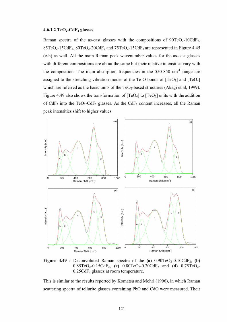
121
4.6.1.2 TeO2-CdF2 glasses
Raman spectra of the as-cast glasses with the compositions of 90TeO2-10CdF2,
85TeO2-15CdF2, 80TeO2-20CdF2 and 75TeO2-15CdF2 are represented in Figure 4.45
(e-h) as well. All the main Raman peak wavenumber values for the as-cast glasses
with different compositions are about the same but their relative intensities vary with
the composition. The main absorption frequencies in the 550-850 cm-1 range are
assigned to the stretching vibration modes of the Te-O bonds of [TeO3] and [TeO4]
which are referred as the basic units of the TeO2-based structures (Akagi et al, 1999).
Figure 4.49 also shows the transformation of [TeO4] to [TeO3] units with the addition
of CdF2 into the TeO2-CdF2 glasses. As the CdF2 content increases, all the Raman
peak intensities shift to higher values.
Figure 4.49 : Deconvoluted Raman spectra of the (a) 0.90TeO2-0.10CdF2, (b) 0.85TeO2-0.15CdF2, (c) 0.80TeO2-0.20CdF2 and (d) 0.75TeO2-0.25CdF2 glasses at room temperature.
This is similar to the results reported by Komatsu and Mohri (1996), in which Raman
scattering spectra of tellurite glasses containing PbO and CdO were measured. Their
(a)
10008006004002000
E
C
D
B
A
Raman Shift (cm-1)
Inte
nsi
ty (
a.u
.)
(b)
E
D
C
B
A
Raman Shift (cm-1)
10008006004002000
Inte
nsi
ty (
a.u
.)
0 200 400 600 800 1000
(c)
E
D
C
BA
Raman Shift (cm-1)
Inte
nsi
ty (
a.u
.)
0 200 400 600 800 1000
(d)
ED
C
BA
Raman Shift (cm-1)
Inte
nsi
ty (
a.u
.)

122
study demonstrated that the number of Te–O–Te linkages in the glasses and so the
connectivity of this network decreases with increasing PbO and CdO contents
(Komatsu and Mohri, 2000). Also it can be explained by the atomic units as the
modifier content increases, a gradual reduction of the tellurium coordination state
from 4 to 3 is observed. The composition of the glass and the chemical nature of the
glassy network modifier are very important for the coordination geometry of the Te
atoms and also has an important effect on the band shape. Raman spectra of other
tellurite glasses which have different network modifiers in their structure display
shifts as well, such as addition of WO3 in to the TeO2-Bi2O3 structure decreases the
intensity of the bands at 440 and 665 cm-1 which attribute to Te–O–Te chains and
[TeO4] units (O’Donnell et al., 2008). Raman scattering and the X-ray absorption
spectroscopy studies conducted by Silva et al. in 2001 concludes that there is a clear
transition between [TeO4] and [TeO3] structures as the PbO content increases in the
binary TeO2-PbO glass system.
Deconvoluted Raman spectra of TeO2-CdF2 glasses are given in Figure 4.49 (a-d).
Five Raman bands at around 168, 256, 429, 656 and 754 cm-1 were observed for
these glasses. The Boson peak which is a characteristic feature of the vitreous state,
for this glass system is around 168 cm-1.
The wavenumber of the maximum values and the relative intensities determined
from all the Gaussian function components for the glasses are given in Table 4.16.
The Raman spectra of all the glasses show a strong band at 656 cm-1 which is
ascribed as the vibrational mode of the [TeO4] groups in the -TeO2. The E peak at
the shoulder of the D peak, is observed at a wavenumber of around 754 cm-1 which is
assigned to the [TeO3] units.
These units are the rearrangements of the [TeO4] units with a lower symmetry. The
two different frequencies are presumptively associated with the two non-equivalent
oxygen atoms. The relatively smaller peak, labeled as C, at 429 cm-1 refers to the
[TeO4] and [TeO3+1] units which is the Te-O-Te linkages as found in the -TeO2
structure.

123
Table 4.16 : Raman Intensity and the wavenumber determined from the deconvoluted Raman spectra of the binary TeO2-CdF2 glass system.
Glass Composition Component Wavenumber (cm-
1) Intensity (a.u.)
0.90TeO2-0.10CdF2 A 167.6 4.0 5.63 B 247.2 1.7 5.36 C 435.3 1.3 7.90 D 656.1 8.3 10.9 E 757.6 1.6 5.43
0.85 TeO2-0.15CdF2 A 167.7 4.0 5.56 B 247.3 1.7 5.43 C 435.6 1.3 7.90 D 656.0 8.3 10.83 E 757.6 1.6 5.42
0.80 TeO2-0.20CdF2 A 168.3 0.2 1.19 B 244.0 1.1 1.07 C 426.0 1.0 1.53 D 657.8 1.1 2.01 E 752.4 1.4 1.54
0.75TeO2-0.25CdF2 A 168.0 0.2 1.62 B 236.1 1.2 2.34 C 416.6 1.3 4.11 D 654.3 1.4 6.52 E 747.4 1.5 7.52
Figure 4.50 (a) represents the relative intensity variations with the CdF2 content. As
it can be seen from the figure, the intensity variations of the C and D peaks are due to
the Te-O-Te bridges between two [TeO4] units and, the Te-O-Te chains in the [TeO4]
and [TeO3+1] four-coordinate atoms, respectively. They both demonstrate a strong
decrease as the amount of CdF2 in the glass composition increases above 15 mol%
while they both stay nearly constant for the compositions having less than 15 mol%
CdF2.
The intensity variation of the E peak which is responsible of the [TeO3] units
increases above 15 mol% CdF2 content while it does not vary for the compositions
having CdF2 content less than 15 mol%. It can be concluded that the addition of the
CdF2 in to the network more than 15 mol% helps the [TeO4] units to transform into
the [TeO3] units. When the effect of the CdF2 and WO3 contents as modifiers in the
binary tellurite glass systems are compared, it can be concluded that no
transformation of the [TeO4] to [TeO3] units is observed above 20 mol% of WO3

124
content while the same transformation process is present for the glasses having the
CdF2 content more than 20 mol%.
Basic structural units of the TeO2-based glasses such as the stretching vibration
modes of the Te-O bonds of [TeO3] and [TeO4] may demonstrate shifts in Raman
spectra when the different network modifier is used in the glass matrix. For instance,
the band which is assigned to the [TeO3] units at 754 cm-1 in the TeO2-CdF2 glasses
appear to be at 770 cm-1 for the TeO2-K2O glasses, at 650 cm-1 for the TeO2-Ga2O3
glasses and at 775 cm-1 for the LiNbO3-TeO2 glasses (Özen et al., 2001; Kabalcı et
al., 2006; Sahar et al; 2007).
As the CdF2 content increases, all the Raman wavenumber values of the C and D
peaks do not shift with the varying CdF2 content in TeO2-CdF2 glasses. However the
Raman wavenumber values of the same the peaks for the binary TeO2-WO3 glasses
showed a shift towards higher wavenumber values with the varying WO3 content.
Figure 4.50 : Compositional dependence of (a) the relative intensity variations of all the Raman peaks and (b) the relative intensity ratios of the Raman peaks at 656-754 cm-1 and 656-429 for the as-cast 90TeO2-10CdF2, 85TeO2-15CdF2, 80TeO2-20CdF2 and 75TeO2-15CdF2 glasses.
Figure 4.50 (b) represents the variation of the concentration for the [TeO4] and
[TeO3+1] groups determined by the intensity ratio of the Raman peaks at 656 and 429
cm-1 indicating the transformation of [TeO4] into [TeO3+1] units. The intensity ratio
of the Raman peaks at 657 and 754 cm-1 related to the transformation of the [TeO4]
to the [TeO3] groups is also given in Figure 4.50 (b). It can be concluded that the
transformation of the [TeO4] to [TeO3+1] units for the compositions is constant below
20 mol% and it decreases after 20 mol% of CdF2 content. As it can also be seen
from the figure that the transformation of the [TeO4] to [TeO3] units which is related
10 15 20 25
(a)
x (mol%)
Re
lativ
e In
ten
sity
A B C D E
10 15 20 25x (mol%)
Re
lativ
e In
tens
ity (
a.u
.)
(b) I656
/I754
I656
/I429

125
to the intensity ratios of the peaks at 656 and 754 cm-1, increases for the
compositions having CdF2 content more than 15 mol%.
Figure 4.51 represents the Raman spectra of the 0.90TeO2-0.10CdF2 glass annealed
at 425 oC, 0.85TeO2-0.15CdF2 glass annealed at 455 oC, 0.80TeO2-0.20CdF2 glass
annealed at 457 oC and 0.75TeO2-0.25CdF2 glass annealed at 450 oC with a heating
rate of 20 oC/min. The annealing temperatures were determined from the DTA
analysis which were conducted by our group previously and reported elsewhere
(Tatar et al., 2008; Tatar et al., 2009a). It can be seen from Figure 4.51 that all the
annealed glasses have similar Raman spectra except the 90TeO2-10CdF2 sample.
Raman spectrum of the 90TeO2-10CdF2 glass demonstrates additional bands at
around 421, 680 and 817 cm-1 which are due to the metastable phase of TeO2 known
as γ-TeO2 in the structure. All the other bands are due to the formation of the stable
α-TeO2 crystalline phase. The XRD studies demonstrated the formation of the
CdTe2O5 phase in the structure hence the convoluted peak at around 700-800 cm-1
which is increasing with the addition of CdF2 into the structure might be due to a Cd-
related vibrational bond. In the study that Komatsu and Mohri (1996) conducted
about the structure of the TeO2-CdO glasses, a Raman spectral study of the
crystallized CdTe2O5 phase have Raman bands in the region of 600-800 cm-1 which
is consistent with our results. It can be seen from the Raman Spectra that the
convoluted peak which belongs to the CdTe2O5 crystalline phase has a relatively
small intensity. The XRD characterizations which were performed in the previous
work of our group also agree with the existence of the -TeO2, γ-TeO2 and the
CdTe2O5 phases that may also be seen in Table 4.15. In a different study conducted
by Komatsu and Mohri (1996), the Raman spectrum of the fully crystallized
CdTe2O5 sample has the highest intensity value at 792 cm-1 and in this study it is
around 770 cm-1. The shift in the Raman peak might be due to the different network
structures which are formed by different anions of O2- and F-.

126
Figure 4.51 : Raman spectra of : (a) 0.75TeO2-0.25CdF2 glass annealed at 450 oC, (b) 0.80TeO2-0.20CdF2 glass annealed at 457 oC, (c) 0.85TeO2-0.15CdF2 glass annealed at 455 oC and (d) 0.90TeO2-0.10CdF2 glass annealed at 425 oC for 1 hour.
4.6.1.3 TeO2-CdF2-WO3 glasses
Raman spectra obtained for the as-cast 0.85TeO2-0.10CdF2-0.05WO3, 0.80TeO2-
0.10CdF2-0.10WO3, 0.75TeO2-0.10CdF2-0.15WO3, 0.75TeO2-0.15CdF2-0.10WO3
glasses are also given in Figure4.45 (i-l). Six Raman bands at around 205, 350, 460,
662, 727 and 921 cm-1 were observed for these glasses. The Raman spectra are
dominated by a broad band having a maximum intensity at around 662 cm-1 with a
shoulder at 727 cm-1 for the ternary TeO2-CdF2-WO3 system and the peak values
demonstrate high shifts with the addition of CdF2 and WO3 content comparing to
those of the binary TeO2-WO3 and TeO2-CdF2 systems.
Deconvoluted Raman spectra of the ternary TeO2-CdF2-WO3 glasses are given in
Figure 4.52 (a-d). All the Gaussian function components, the wavenumber of the
maximum values and the relative intensities of the TeO2-CdF2-WO3 glasses are given
in Table 4.17.

127
Figure 4.52 : Deconvoluted Raman spectra of the (a) 0.85TeO2-0.10CdF2-0.05WO3, (b) 0.80TeO2-0.10CdF2-0.10WO3, (c) 0.75TeO2-0.10CdF2-0.15WO3 and (d) 0.75TeO2-0.15CdF2-0.10WO3 glasses.
The peak A at around 205 cm-1 belongs to the heavy metal vibrational modes, the
peak C at around 460 cm-1 belongs to the Te-O-Te chains in between two [TeO4]
four-coordinate atoms, the D peak at around 662 cm-1 also belongs to the Te-O-Te
bridges between two [TeO4] units in the α-TeO2 structure, the peak at around 727
cm-1 belongs to the Te=O bonds involving three-coordinate Te atoms or more known
as [TeO3+1] units. Finally, the G peak at around 921 cm-1 belongs to the W=O bonds
involving single six-coordinate W atoms, as it was also observed for the binary
TeO2-WO3 glasses.
0 200 400 600 800 1000
(a)
F
E
DC
BA
Raman Shift (cm-1)
Ra
ma
n S
catte
ring
Inte
nsi
ty (
a.u.
)
0 200 400 600 800 1000
(b)
F
E
D
C
B
A
Raman Shift (cm-1)
Ram
an S
catte
ring
Inte
nsi
ty (
a.u
.)
0 200 400 600 800 1000
(c)
F
E
DC
BA
Raman Shift (cm-1)
Ra
ma
n S
catte
rin
g In
ten
sity
(a
.u.)
0 200 400 600 800 1000
(d)
F
ED
CB
A
Raman Shift (cm-1)
Ram
an S
cattering Inte
nsi
ty (
a.u
.)

128
Table 4.17 : Decomposition of deconvoluted Raman spectra of the ternary TeO2-CdF2-WO3 glass system.
Glass Composition Component Wavenumber (cm-1) Intensity (a.u.) 0.85TeO2-0.10CdF2-0.05WO3 A 201.3 0.3 805.13
B 265.5 1.5 829.12 C 433.3 0.8 1368.24 D 654.3 0.7 1702.63 E 747.3 1.7 1256.72 F 920.6 0.4 512.21
0.80TeO2-0.10CdF2-0.10WO3 A 202.8 0.4 463.42 B 262.1 2.1 517.43 C 434.6 1.9 709.04 D 653.1 2.0 613.21 E 740.9 10.7 753.82 F 923.6 0.5 488.60
0.75TeO2-0.10CdF2-0.15WO3 A 210.9 0.3 613.92 B 330.9 1.6 769.03 C 476.4 1.2 538.02 D 658.8 0.9 593.23 E 735.3 14.4 903.12 F 925.6 1.5 710.43
0.75TeO2-0.15CdF2-0.10WO3 A 204.6 0.3 429.24 B 291.3 1.9 377.92 C 440.4 3.1 362.74 D 655.6 4.5 482.54 E 743.0 6.5 508.83 F 915.6 1.5 433.02
Figure 4.53 (a) represents the relative intensity variations with the modifier contents
for the ternary glass system. As it can be seen from the figure, the intensity variation
of the D peak which is responsible of the Te-O-Te bridges between two [TeO4] units
and also the C peak which is responsible of the Te-O-Te chains in the [TeO4] and
[TeO3+1] four-coordinate atoms, demonstrate a decrease as the amount of WO3 in the
glass composition increases to 15 mol% while the CdF2 content in the matrix was
kept constant 10 mol%. At the same time it can be seen that the intensity variation of
the E peak which is responsible of the [TeO3] units increases till the WO3 content is
10 mol% and then decreases. It can be concluded that the addition of the WO3 in to
the ternary glass system until 20 mol% helps the [TeO4] units to transform into the
[TeO3] units but addition of WO3 content into the glass more than 20 mol% causes
the formation of the bands containing W. The glass forming ability of the system
decreases for the compositions containing more than 10 mol% WO3 content.

129
Figure 4.53 (b) represents the variation of the concentration for the [TeO4] and
[TeO3+1] groups determined by the intensity ratio of the Raman peaks at 656 and 429
cm-1 related to the transformation of [TeO4] into [TeO3+1] units. The intensity ratio of
the Raman peaks at 656 and 754 cm-1 related to transformation of the [TeO4] to the
[TeO3] groups is also given in Figure 4.53 (b). It can be seen from the figure that the
ratio of the 656 and 754 cm-1 peaks shows a fast decrease when the WO3 content is
varied from 5 to 15 mol%. This is a different behavior than those observed in the
binary TeO2-WO3 and TeO2-CdF2 systems in which the same ratio was almost
unchanged for either WO3 or CdF2 content less than 15 mol%.
The intensity ratio of the Raman peaks at 656 and 429 cm-1 for the compositions
below 10 mol% WO3 content decreases rapidly and starts to increase for the
compositions having WO3 content above 10 mol% which is a similar behavior
observed in the binary TeO2-CdF2 system. This indicates that the CdF2 content has
more ability to form [TeO3+1] units than WO3. The ability of the CdF2 for
transforming [TeO4] to [TeO3+1] units was also observed when the WO3 content was
10 mol% and CdF2 content was increased from 10 to 15 mol% in the ternary glass
system (Figure 4.53 (b)).
Figure 4.53 : Compositional dependence of (a) the relative intensity variations of all the Raman peaks and (b) the relative intensity ratios of the Raman peaks at 662-727 cm-1 and 662-460 for the as-cast 0.85TeO2-0.10CdF2-0.05WO3, 0.80TeO2-0.10CdF2-0.10WO3, 0.75TeO2-0.10CdF2-0.15WO3 and 0.75TeO2-0.15CdF2-0.10WO3 glasses.
Figure 4.54 (a-d) represents the Raman spectra of the 0.85TeO2-0.10CdF2-0.05WO3,
0.80TeO2-0.10CdF2-0.10WO3, 0.75TeO2-0.10CdF2-0.15WO3, 0.75TeO2-0.15CdF2-
0.10WO3 glasses annealed above their crystallization temperatures determined from
DTA results. The DTA scans, XRD characterizations and the crystallization kinetics
1 2 3 4
Re
lativ
e In
ten
sity
(a
.u.)
(a) A B C D E F
Composition1 2 3 4
Composition
Re
lativ
e In
tens
ity (
a.u
.)
(b) I662
/I727
I662
/460

130
of these glasses will be presented as a different work in the future. Figure 4.54 (a)
represents the Raman spectra of the 0.85TeO2-0.10CdF2-0.05WO3 glass annealed at
420 and 560 oC. Table 4.15 represents the crystalline phases determined from the
Raman spectra together with those obtained from the XRD measurements for
comparison.
As it can be seen from Table 4.15, the XRD results of the 0.85TeO2-0.10CdF2-
0.05WO3 glass annealed at 420 oC demonstrate γ-TeO2, WO3 and δ-TeO2 phases in
its structure. Raman spectra of the 0.85TeO2-0.10CdF2-0.05WO3 glass annealed at
420 oC demonstrate peaks at 423, 611, 683, 818 cm-1 referring to γ-TeO2 and one
peak at 913 cm-1 referring to WO3. As Mirgorodsky et al. (2000) described, the
structure of the δ-TeO2 is a superposition of a continuous background and a series of
discrete lines. Hence the glass annealed at 420 oC has an elevated background and
the XRD results demonstrate the existence of the δ-TeO2 phase, we may conclude
that the Raman spectra of the 0.85TeO2-0.10CdF2-0.05WO3 glass annealed at 420 oC
includes γ-TeO2, WO3 and δ-TeO2 structures.
Raman spectra of the 0.85TeO2-0.10CdF2-0.05WO3 glass annealed at 560 oC
demonstrate α-TeO2 (232-391, 587, 646, 717 cm-1), WO3 (913 cm-1) in its structure
which is consistent with the XRD results. Figure 4.54 (b) represents the Raman
spectra of the 0.80TeO2-0.10CdF2-0.10WO3 glass samples annealed at 420 and 560 oC. 0.80TeO2-0.10CdF2-0.10WO3 glass is similar to the Raman spectra of the
0.85TeO2-0.10CdF2-0.10WO3 glass. It demonstrates γ-TeO2 (423, 611, 683, 818 cm-
1), WO3 (903 cm-1) and δ-TeO2 phases when annealed at 420 oC and α-TeO2 (232-
391, 587, 646, 757 cm-1) and WO3 (880 cm-1) phases when annealed at 560 oC.
Figure 4.54 (c) represents the Raman spectra of the 0.75TeO2-0.10CdF2-0.15WO3
glass samples annealed at 420, 560 and 580 oC temperatures.
When the Raman spectra given in Figure 4.54 (a-c) are compared, it can be seen that
the Raman spectra 0.75TeO2-0.10CdF2-0.15WO3 glass is different than those of the
0.85TeO2-0.10CdF2-0.05WO3 and 0.80TeO2-0.10CdF2-0.10WO3 glasses. 0.75TeO2-
0.10CdF2-0.15WO3 glass annealed at 420 oC demonstrates Raman peaks at 231-391,
589, 646, 717 cm-1 which refer to the α-TeO2 and the peak at 880 cm-1 which refers
to WO3. The XRD results show that the glass has only δ-TeO2 phase in its structure
when annealed at 420 oC. This may be due to the fact that the intensity of the α-TeO2
and WO3 phases are too small to be observed with XRD. When the glass is anneal to

131
560 oC, the peaks at 273, 717 and 807 cm-1 increase. The XRD results demonstrate
that the glass has α-TeO2, WO3, Cd2(Te3O9) and another unidentified phase which is
labeled as ε in the Table 4.15. The increment of the peaks at 273, 717 and 807 cm-1
might be explained by the unidentified phase. Figure 7(d) represents the Raman
spectra of the 0.75TeO2-0.15CdF2-0.10WO3 glass samples annealed at 420, 560 and
580 oC temperatures.
Raman spectra of the 0.75TeO2-0.10CdF2-0.15WO3 glass annealed at 420 oC
demonstrate a continuous background similar to Raman spectra of the as-cast
0.75TeO2-0.10CdF2-0.15WO3 glass. The XRD results demonstrate that the only
present phase in this sample is the δ-TeO2 phase. Raman spectra of the 0.75TeO2-
0.15CdF2-0.10WO3 glass samples annealed at 560 and 580 o C temperatures
demonstrate similar peaks and may refer to the α-TeO2 (232-391, 590, 646, 720 cm-
1), WO3 (880cm-1) structures.
As Komatsu et al. (1999) demonstrated in their work about the TeO2-CdO glasses,
the crystallized CdTe2O5 phase existed in the region of 600-800 cm-1. The XRD
studies of the ternary TeO2-CdF2-WO3 glasses demonstrated the formation of the
Cd2(Te3O9) phase in the structure. If the Raman spectra of the annealed 0.75TeO2-
0.10CdF2-0.15WO3 and the 0.75TeO2-0.15CdF2-0.10WO3 glasses are compared, it
can be seen that the convoluted peak at around 700-800 cm-1 in the 0.75TeO2-
0.15CdF2-0.10WO3 glass reaches its maximum value where the CdF2 content has its
highest value. Hence it can be concluded that; because the intensity of the concluded
peak in the region of 700-800 cm-1 both in the binary TeO2-CdF2 and ternary TeO2-
CdF2-WO3 glasses increase hence this peak might reveal to a Te-Cd, Te-O or Te-O-
Cd bonds.

132
Figure 4.54 : Raman spectra of (a) 0.85TeO2-0.10CdF2-0.05WO3 glass annealed at 420 and 560 oC for one hour, (b) 0.80TeO2-0.10CdF2-0.10WO3 glass annealed at 420 and 560 oC for one hour, (c) 0.75TeO2-0.10CdF2-0.15WO3 glass annealed at 420 and 560 oC for one hour and 580 oC for 24 hours and (d) 0.75TeO2-0.15CdF2-0.10WO3 glass annealed at 420 and 560 oC for one hour and 580 oC for 24 hours.
4.6.2 Conclusions
The effect of the modifier content on the microstructure and the crystallization
behavior for the TeO2-WO3, TeO2-CdF2 and TeO2-CdF2-WO3 were investigated. For
the binary TeO2-WO3 glass system, the transformation from [TeO4] to [TeO3] units
and also [TeO4] to [TeO3+1] units mainly occur for the WO3 content between 15-20
mol% and also it may be suggested that the transformation of the [TeO4] units to
[TeO3+1] units is relatively less dependent on the WO3 content in the glass indicating
that the effect of WO3 as a modifier on conversion of the [TeO4] to [TeO3+1] is
relatively small. Transformation of the [TeO4] to [TeO3] units slows down above 20
mol% of WO3 content since the formation of the W-related bonds starts to appear
while the same transformation process is present for the glasses having the CdF2
content increases above 20 mol%. The amount of crystallization due to annealing at
the first exotherm temperatures decreases with the increasing WO3 content and this
shows that the glass forming ability of the binary TeO2-WO3 glasses increases with
WO3 content.
200 400 600 800 1000
560oC
(a)
913760717283
232 335
818
423
391
611
587
683
646
420oC
Raman Shift (cm-1)
Ra
ma
n S
catte
ring
In
tens
ity (
a.u
.)
560oC
(b)
757232 335
909
880
818
423
391
587
611
683
646
1000800600400200
Raman Shift (cm-1)
Ram
an
Sca
tter
ing
Inte
nsi
ty (
a.u.
)
420oC
200 400 600 800 1000
580oC
560oC
(c)
760231
420oC
273327
391589 885
807
717
646
Ra
ma
n S
catte
ring
Inte
nsi
ty (
a.u
.)
Raman Shift (cm-1)200 400 600 800 1000
580oC
560oC
(d)
299285 336232 880
720 766
391
590
646
Raman Shift (cm-1)
Ra
man
Sca
tter
ing
In
ten
sity
(a
.u.)
420oC

133
For the binary TeO2-CdF2 glass system the transformation of the [TeO4] to [TeO3+1]
units for the compositions below 20 mol% CdF2 is constant and it decreases after 20
mol% of CdF2 content. The transformation of the [TeO4] units into [TeO3] units
increases for the compositions with CdF2 content more than 15 mol%.
For the ternary TeO2-CdF2-WO3 glass system the ratio of the 656 and 754 cm-1 peaks
which is related to the transformation of the [TeO4] to the [TeO3] groups shows a fast
decrease when the WO3 content is varied from 5 to 15 mol%. This is a different
behavior than those observed in the binary TeO2-WO3 and TeO2-CdF2 systems in
which the same ratio was almost unchanged for either WO3 or CdF2 content was less
than 15 mol%. The intensity ratio of the Raman peaks at 656 and 429 cm-1 which is
due to the transformation of the [TeO4] units to [TeO3+1] units for the compositions
below 10 mol% WO3 content decreases rapidly and starts to increase when the WO3
content is above 10 mol%. This is a similar behavior observed in the binary TeO2-
CdF2 system and indicates that the CdF2 content has more ability to form [TeO3+1]
units than WO3.
The increment of the peaks at 273, 717 and 807 cm-1, might be explained by the
unidentified phase formation in addition to the other phases since the XRD results
demonstrate that the TeO2-CdF2-WO3 glass has α-TeO2, WO3, Cd2(Te3O9) and an
unidentified phase labeled as ε. This unidentified phase was not however observed in
neither Raman spectra nor XRD results of the binary TeO2-WO3 and TeO2-CdF2
glass systems.
Raman spectra of the ternary TeO2-CdF2-WO3 glass system demonstrate the
existence of the metastable γ-TeO2, δ-TeO2 and stable α-TeO2 polymorphs of TeO2
in its structure. Both the Raman Spectra and XRD results showed that the metastable
δ-TeO2 phase forms at 420 oC and transforms into the stable α-TeO2 structure at 560 oC. The δ-TeO2 phase has a continuous background-like Raman spectrum and
demonstrates no sharp peaks. The transformation of the metastable γ -TeO2 phase
into the stable -TeO2 was observed for the (1-x)TeO2-xWO3 (where x= 0.15, 0.20,
0.25), 0.90Te2-0.10CdF2 as well as the 0.85TeO2-0.10CdF2-0.05WO3 and 0.80TeO2-
0.10CdF2-0.10WO3 glasses.

134

135
5. DISCUSSION
As stated previously in this dissertation, four different compositions of glasses with
0.90TeO2-0.10CdF2, 0.85TeO2-0.15CdF2, 0.80TeO2-0.20CdF2 and 0.75TeO2-
0.25CdF2 in molar ratio, three different composition of glasses with 0.85TeO2-
0.10CdF2-0.05PbF2, 0.80TeO2-0.10CdF2-0.10PbF2 and 0.75TeO2-0.10CdF2-
0.15PbF2 in molar ratio, four different compositions with 0.85TeO2-0.10CdF2-
0.05WO3, 0.80TeO2-0.10CdF2-0.10WO3, 0.75TeO2-0.10CdF2-0.15WO3 and
0.75TeO2-0.15CdF2-0.10WO3 in molar ratio, three glass compositions of 0.90TeO2-
0.10V2O5, 0.80TeO2-0.20V2O5 and 0.50TeO2-0.50V2O5 in molar ratio were
investigated. In order to understand the effect of the modifier content on the thermal
properties, microstructure and the crystallization behavior of the glass and glass-
ceramics, DTA, XRD, Raman Spectroscopy and SEM/EDS techniques were used.
DTA investigations have shown that increasing the CdF2 content in the TeO2-CdF2
binary glass system slightly increases the glass transition temperature, Tg. On the
other hand the increment of the modifier in the glass results in the decrement of the
crystallization peak, Tp, and the melting temperatures, Tm. The thermal stability of the
glass system changes with the addition of the modifier, as well. The smallest value of
the thermal stability determined in the four different glass compositions of the binary
TeO2-CdF2 glass system is 57 oC and belongs to the 0.75TeO2–0.25CdF2 glass. This
evidences the difficulty of obtaining an amorphous glass structure with high CdF2
contents. Thermal stability values of these glasses have varying values. The binary
0.90TeO2–0.10 CdF2 glass has a value of 88 oC, the 0.85TeO2–0.15CdF2 glass has a
value of 66 oC, the 0.80TeO2–0.20CdF2 glass has a value of 119 oC and the the
0.75TeO2–0.25CdF2 glass has a value of 57 oC. The reason for the change in the
thermal stability values may be due to the change in the glass composition due to the
losses of the tellurium and fluorine atoms during the glass preparation.
As it was stated ealier in the thesis that some studies of the extended X-ray
absorption fine structure (EXAFS) show the possible decrease in the coordination

136
number of CdF2 can be explained by the formation of the [CdO4] units. It was also
claimed that the tellurium and fluorine atoms may diminish during the glass
preparation and cadmium oxide may form which was given in Eq. (2.12) (Silva et al.,
2002a; Bueno et al., 2005). Hence, the oxygen atoms preferentially surround the
cadmium ions even though there is a fluoride environment (Silva et al., 2002a).
Atomic absorption tests of these glasses were conducted and the Te and Cd
concentration of these glasses were investigated. It was observed that the Te content
in the 0.90TeO2–0.10 CdF2 glass diminishes and goes down to a value of 0.88 mol %
of TeO2.
DTA scans show that there are different number of exothermic peaks for the glasses
in the binary TeO2–CdF2 glass system. It can be claimed that multiple exothermic
reactions taking place in the smaller heating rates, add up and appear as sums and
overlaps in higher heating rates. Further, DTA investigations demonstrate that the
glass transition, crystallization and the melting temperatures of the as-cast 0.80TeO2-
0.20CdF2 glass with different heating rates of 5 oC, 10 oC and 20 oC are found to be
varying with the heating rate. It can be seen that as the heating rate increases, the
glass transition and the crystallization temperatures increase. Even though thermal
stability of the as-cast 0.80TeO2-0.20CdF2 glass changes with different heating rates,
it does not have a substantial effect on the thermal stability of the 0.90TeO2–0.10
CdF2, 0.85TeO2–0.15CdF2 and the 0.75TeO2–0.25CdF2 glasses. It can be claimed
that this may be due to the change in the composition of these glasses due to the
reaction taking place in Eq. (2.12).
DTA investigations demonstrate that increasing the PbF2 content in the ternary TeO2-
CdF2-PbF2 glass system decreases the glass transition temperatures. If the binary
TeO2-CdF2 and the ternary TeO2-CdF2-PbF2 glass systems are compared with each
other, it can be seen that the addition of the PbF2 into the binary TeO2-CdF2 system
decreases the glass transition temperatures and increases the thermal stability values
of these glasses. The glass transition temperature values of the binary TeO2-CdF2
system is in the range of 316-320 oC but the glass transition temperature values for
the ternary TeO2-CdF2-PbF2 system is in the range of 273-301 oC for the heating rate
of 20 oC/min.
The thermal stability values of the binary TeO2-CdF2 system is in the range of 57-
119 oC but the thermal stability values for the ternary TeO2-CdF2-PbF2 system is in

137
the range of 118-173 oC for the heating rate of 20 oC/min. It can be understood that
by adding PbF2 content into the TeO2-CdF2 system, it is possible to obtain more
thermally stable glasses. The as-cast 0.75TeO2-0.10CdF2-0.15PbF2 glass with the
highest content of PbF2 for a heating rate of 20 oC/min is the most susceptible to
form glass among the these glass compositions. Its glass forming tendency value of
173 oC is much higher than the binary TeO2-CdF2 glasses.
Increasing the heating rate contributes to the increase of glass transition and
crystallization peak temperatures in both the binary TeO2 – CdF2 and ternary TeO2-
CdF2-PbF2 systems.
Increasing the WO3 contents in the ternary TeO2-CdF2-WO3 system contribute to
increases in glass transition and the crystallization temperatures. The thermal
stability values of these glasses slightly increase with the addition of the WO3
content in the glass system. The 0.85TeO2-0.10CdF2-0.05WO3, 0.80TeO2-0.10CdF2-
0.10WO3 and 0.75TeO2-0.10CdF2-0.15WO3 glasses have two exotherms which may
refer to crystallization or transformation of a phase and two endotherms which may
refer to melting processes. For the 0.85TeO2-0.10CdF2-0.05WO3, 0.80TeO2-
0.10CdF2-0.10WO3 and 0.75TeO2-0.10CdF2-0.15WO3 samples which have the same
CdF2 content (10 mol% CdF2) the glass transition and the melting temperatures
increase with the increasing WO3 content. The 0.75TeO2-0.15CdF2-0.10WO3 sample
differs from the other compositions since it does not demonstrate a distinctive glass
transition temperature.
Compared to the thermal stability values of the binary TeO2-CdF2 and also the
ternary TeO2-CdF2-PbF2 glass systems, the ternary TeO2-CdF2-WO3 system has the
lowest glass transition and thermal stability values. Addition of the WO3 and CdF2
modifier contents together into the TeO2 structure lowers the thermal stability values
of the glass system. On the contrary, PbF2 increases the thermal stability values of
the ternary TeO2-CdF2-PbF2 glass system.
DTA investigations conducted on the as-cast 0.90TeO2-0.10V2O5, 0.80TeO2-
0.20V2O5 and 0.50TeO2-0.50V2O5 glasses show that the addition of V2O5 content
into the glass structure lowers the glass transition and the melting temperatures. The
addition of the V2O5 modifier content into the binary TeO2-V2O5 glass system
decreases the glass transition temperature. The glass transition values of the binary
TeO2-V2O5 system are lower than those of the TeO2-CdF2 glass system. DTA curves

138
show that the addition of the V2O5 content into the glass system decreases the glass
forming tendency of the glasses and increases the number of exothermic peaks in the
thermograms of the glasses.
The XRD patterns of as-cast TeO2-CdF2 glasses except for the 0.75TeO2–0.25CdF2
as-cast glass show typical amorphous clustering of glassy solids. Regardless of the
heating rate two dominant crystalline phases are formed which are -TeO2 and
CdTe2O5 phases in the 0.80TeO2-0.20CdF2 binary glass composition. Triclinic
CdTe2O5 phase is observed at a lower heating rate while the CdTe2O5 phase forms at
higher heating rates which has a monoclinic crystal structure.
When the 0.90TeO2–0.10CdF2 glass was annealed, the stable -TeO2, metastable -
TeO2 and the CdTe2O5 phases crystallized in its microstructure. It is understood that
the scanning rate does not have an effect on the formation or the transformation of
the crystalline phases for this glass composition. When the 0.85TeO2–0.15CdF2 glass
was annealed, CdTe2O5 and also the -TeO2 crystalline phases were observed. The
metastable phase, -TeO2, was not observed in the XRD scans of the samples
annealed at neither temperatures. The XRD patterns of the annealed 0.75TeO2–
0.25CdF2 glasses revealed that the -TeO2, -TeO2 and CdTe2O5 crystalline phases
were present in their microstructures.
All as-cast 0.85TeO2–0.10CdF2–0.05PbF2, 0.80TeO2–0.10CdF2–0.10PbF2 and
0.75TeO2–0.10CdF2–0.15PbF2 glasses demonstrate typical amorphous XRD
patterns. The XRD patterns of all ternary TeO2 – CdF2 – PbF2 glasses heat-treated at
460 oC had the crystalline -TeO2 phase in their microstructures.
It is observed that the 0.85TeO2-0.10CdF2-0.05WO3 sample in the as-cast condition
has the -TeO2 crystalline phase in its structure. Even though the formation of the -
TeO2 phase was not observed in any of the studied binary TeO2-CdF2 glass
compositions, the present study shows that within the ternary TeO2-CdF2-WO3
system, it is possible to observe the -TeO2 phase (Tatar et al., 2009a). The
0.80TeO2-0.10CdF2-0.10WO3 and the 0.75TeO2-0.10CdF2-0.15WO3 samples have
amorphous structures in the as-cast conditions. On the other hand the 0.75TeO2-
0.15CdF2-0.10WO3 sample does not have an amorphous structure in the as-cast
condition and contains the metastable -TeO2 phase.

139
When both the 0.85T5eO2-0.10CdF2-0.05WO3 and the 0.80TeO2-0.10CdF2-0.10WO3
glasses were annealed at 420 oC for 30 minutes, γ-TeO2 and -TeO2 phases were
formed. Further heat-treatment of theses glasses results in the transformation of the
metastable -TeO2 and γ-TeO2 phases into the stable -TeO2 phase. In addition, a
new phase which is labeled as unidentified in is formed as well.
When the 0.75TeO2-0.10CdF2-0.15WO3 glass was annealed at 420 oC for 30
minutes, -TeO2 solid solution phase and also very little amount of γ-TeO2 crystals
form in the microstructure. On the other hand only the stable α-TeO2, WO3 , and the
new unidentified phases are formed when this glass annealed at 560 oC for 30
minutes. Unlike the 0.85TeO2-0.10CdF2-0.05WO3 and 0.80TeO2-0.10CdF2-0.10WO3
glasses which have less than 10 mol% WO3 contents, the formation of the WO3
phase takes place in the 0.75TeO2-0.10CdF2-0.15WO3 glass which contains 15 mol%
WO3. Different than the other three compositions, when the 0.75TeO2-0.15CdF2-
0.10WO3 glass is annealed at 420 oC and at 560 oC temperatures for 30 minutes, the
-TeO2 phase is the only crystalline phase. Further heat-treatment of the glass for
120 minutes at 560 oC results in the transformation of this phase into the stabe α -
TeO2. In addition to the -TeO2 and the unidentified phase, CdTe2O5 phase which
has a monoclinic crystal structure form as well.
As-cast 0.90TeO2-0.10V2O5, 0.80TeO2-0.20V2O5 and 0.50TeO2-0.50V2O5 glasses
have amorphous structures. The XRD patterns of the 0.90TeO2-0.10V2O5 and the
0.80TeO2-0.20V2O5 show that when these glasses were annealed -TeO2 and
Te2V2O9 crystalline phases were formed. On the other hand, when the 0.50TeO2-
0.50V2O5 glass was annealed only the V2O5 crystalline phase was formed. It was
understood that the -TeO2 formation was not observed at any temperature when the
0.50TeO2-0.50V2O5 glass was annealed.
SEM images of the 0.80TeO2-0.20CdF2 glass annealed with different heating rates at
different temperatures reveal mostly glassy morphologies. Paratellurite (α-TeO2)
crystalline formation is observed in the SEM images for this glass composition as
dendrites. As the heating rate and temperature increases the microstructure of the
glass changes and the number and the sizes of the grains become larger which
indicates the increment of the volume fraction of the crystalline phase with respect to
that of the glass phase.

140
SEM micrographs taken from the surface and the cross-sections of the 0.90TeO2–
0.10CdF2, 0.85TeO2–0.15CdF2 and 0.75TeO2–0.25CdF2 glass-ceramics reveal that
the crystallization occur in three dimensions and thus it is the bulk crystallization
type. SEM and SEM/EDS investigations of the 0.90TeO2–0.10CdF2 sample heat-
treated with different heating rates show similar morphologies. The microstructures
of the 0.90TeO2–0.10CdF2, 0.85TeO2–0.15CdF2 and 0.75TeO2–0.25CdF2 glasses
comprise elongated centrosymmetric stripe-shaped crystalline regions existed both in
the surface and cross-section. SEM investigations of the 0.90TeO2–0.10CdF2 glass
reveal that there are actually two different crystal formations interconnected with
each other. The center of this structure is Cd-rich clover-like while the surrounding
needle-like structure is Te rich. The TeO2-rich crystalline phase has a radial needle-
like morphology in all compositions whereas the CdTe2O5 crystalline phase has a
tabular parallel to the cleavage and foliated morphology detected in only 0.75TeO2–
0.25CdF2 glass composition. SEM investigations conducted on the 0.85TeO2-
0.10CdF2-0.05WO3, 0.80TeO2-0.10CdF2-0.10WO3, 0.75TeO2-0.10CdF2-0.15WO3
and 0.75TeO2-0.15CdF2-0.10WO3 samples revealed that the disordered crystals
observed in this glass system were composed by the �-TeO2 paratellurite phase. The
unidentified phase is observed as small blocks of ordered crystals. SEM micrographs
taken from the 0.75TeO2-0.15CdF2-0.10WO3 sample demonstrate regular array of
crystals which resemble long lines of vertebra-like structures and refer to the δ-TeO2
solid solution phase.
SEM/EDS investigations performed on the heat-treated 0.90TeO2-0.10V2O5,
0.80TeO2-0.20V2O5 and 0.50TeO2-0.50V2O5 glasses show that the oriented needle-
like crystalline regions might belong to the Te2V2O9 crystals and the diamond-like
lozenge crystals might be composed of paratellurite crystalline phase. SEM
micrographs of the 0.80TeO2-0.20V2O5 glass heat treated at 355 oC and 430 oC for
30 minutes demonstrate square shaped crystalline regions and tilted hexagonal-like
regions which are composed of the paratellurite phase. Following annealing at 430 oC for 30 minutes of the 0.80TeO2-0.20V2O5 glass was heat treated, additional to the
two distinct types of crystal formations, triangular crystals are also formed which are
composed of the paratellurite phase. On the other hand, the needle-like crystalline
regions belong to the Te2V2O9 phase.

141
The transformation of the [TeO4] units into the [TeO3] and [TeO3+1] units mailly
takes place when the WO3 content in the binary TeO2-WO3 glass system is between
15-20 mol%. The transformation of the [TeO4] units to [TeO3+1] units is relatively
less dependent on the WO3 content in the glass structure. This indicates that the
effect of WO3 as a modifier on conversion of the [TeO4] to [TeO3+1] is relatively
small for the TeO2-WO3 glass system. Transformation of the [TeO4] to [TeO3] units
decreases above 20 mol% of WO3 content since the formation of the W-related
bonds starts to appear. The same transformation process takes place for the glasses
having the CdF2 content and it increases for the glasses having CdF2 content more
than 20 mol%.
On the other hand the transformation of the [TeO4] into the [TeO3+1] units is constant
for the glasses with compositions below 20 mol% CdF2 and decreases for the
compositions with CdF2 content more than 20 mol%. The transformation of the
[TeO4] units into [TeO3] units increases for the compositions with CdF2 content more
than 15 mol%.
The transformation of the [TeO4] units into [TeO3] units increases for the
compositions with CdF2 content more than 15 mol%. For the ternary TeO2-CdF2-
WO3 glass system the ratio of the 656 and 754 cm-1 peaks which is related to the
transformation of the [TeO4] to the [TeO3] groups shows a fast decrease when the
WO3 content is varied from 5 to 15 mol%. This is a different behavior than those
observed in the binary TeO2-WO3 and TeO2-CdF2 systems in which the same ratio
was almost unchanged for either WO3 or CdF2 contents less than 15 mol%. The
intensity ratio of the Raman peaks at 656 and 429 cm-1 which is due to the
transformation of the [TeO4] units to [TeO3+1] units for the compositions below 10
mol% WO3 content decreases rapidly and starts to increase when the WO3 content is
above 10 mol%. This is a similar behavior observed in the binary TeO2-CdF2 system
and indicates that the CdF2 content has more ability to form [TeO3+1] units than
WO3. The increment of the peaks at 273, 717 and 807 cm-1, might be explained by
the unidentified phase formation in addition to other phases since the XRD results
demonstrate that the TeO2-CdF2-WO3 glass has α-TeO2, WO3, Cd2(Te3O9) and an
unidentified phase labeled as ε. This unidentified phase was not however observed in
neither Raman spectra nor XRD results of the binary TeO2-WO3 and TeO2-CdF2
glass systems.

142
Raman spectra of the ternary TeO2-CdF2-WO3 glass system demonstrate the
existence of the metastable γ-TeO2, δ-TeO2 and stable α-TeO2 polymorphs of TeO2
in its structure. Both the Raman Spectra and XRD results showed that the metastable
δ-TeO2 phase forms at 420 oC and transforms into the stable α-TeO2 structure at 560 oC. The δ-TeO2 phase has a continuous background-like Raman spectrum and
demonstrates no sharp peaks.
Raman spectra of the heat-treated TeO2-CdF2-PbF2 ternary glass-ceramics reveal
three main Raman bands at 390, 587 and 665 cm-1 which belong to the -TeO2
crystalline phase. The shoulder peak observed at the frequency 725 cm-1 is assigned
to the TeO3-TeO3+1 units. The addition of PbF2 as a network modifier into the glass
structure forces the transition of the glass network from TeO4 trigonal bipyramids
units to the TeO3 trigonal pyramid structural units. The results indicate that TeO4
trigonal bipyramids units divert to the TeO3-TeO3+1 trigonal pyramid units hence
causing the reduction of the tellurium coordination state from 4 to 3.
For the TeO2-V2O5 glasses, the peaks at the frequencies 218, 235 and 252 cm-1 peaks
might refer to the vibrations of TeO3 tp overlapped by V–O–V(Te) vibrations
between polyhedral. As the TeO2 content increases, the intensity of these peaks
decrease.
In order to study the crystallization kinetics and the activation energy of the glasses,
the Differential thermal analysis (DTA) thermograms of as-cast 0.85TeO2–
0.10CdF2–0.05PbF2, 0.80TeO2–0.10CdF2–0.10PbF2 and 0.75TeO2–0.10CdF2–
0.15PbF2 glass samples scanned at the heating rates of 5, 10 and 20 oC/min were
conducted. It was observed that the one-dimensional growth of crystals was
dominant for the crytallization processes in these glasses. The activation energy
values of the crystallization peaks varied between 162.5 and 78.7 kJ/mol for the
exotherms. The SEM investigations support the formation of the crystalline phases
via one-dimensional crystallization mechanism since centrosymmetrical
crystallization was observed in the cross-sectional micrographs of all annealed
samples. It was understood that the addition of the PbF2 content into the glass
compositions reduced the activation energy which was necessary for the formation of
the paratellurite phase.

143
6. CONCLUSIONS
Amorphous glass structure was obtained for all of the studied glass compositions
except for the 0.75TeO2-0.25CdF2, 0.85TeO2-0.10CdF2-0.05WO3 and 0.75TeO2-
0.15CdF2-0.10WO3 samples. The ternary TeO2-CdF2-WO3 system is found to be the
hardest system to form glass structure with conventional methods among the other
studied glass systems in this thesis. It is be suggested that CdF2, PbF2, V2O5 and WO3
act as network modifiers and TeO2 is the main glass former in all of the obtained
glass systems.
DTA investigations conducted on the as-cast glasses have shown that the heating rate
may cause shifts in the glass transition and the crystallization temperatures.
Depending on the glass system, as the heating rate increases, the glass transition and
crystallization temperatures may shift to lower or higher values. DTA scans
demonstrate that with as the glass is heated with higher heating rates, the peak values
of the exotherms gets higher. Exothermic peaks observed in the DTA scans may
either refer to the formation or transformation of a crytalline phase.
For the ternary TeO2-CdF2-PbF2 glass system, the addition of PbF2 content decreases
the glass transition and the melting temperatures. On the other hand, for the ternary
TeO2-CdF2-WO3 glass system increasing the WO3 content increases the glass
transition and the crystallization temperatures. It is observed that for the binary
TeO2-CdF2 glass system the thermal stability values decreases with the increasing
CdF2 content. Thermal stability of the ternary TeO2-CdF2-PbF2 glasses increases
with the addition of PbF2 into the glass structure as a modifier. Similarly, the
addition of the WO3 increases the thermal stability for the ternary TeO2-CdF2-WO3
glasses. Also for the binary TeO2-V2O5 glass system, as the V2O5 content increases
the thermal stability of these glasses increase.

144
SEM investigations of the surface and the cross-sections for the glass compositions
that belong to the TeO2–CdF2 glass system revealed that crystallization is three
dimensional and may refer to the bulk crystallization type.

145
REFERENCES
Akagi, R., Handa, K., Ohtori, N., Hannon, A. C., Tatsumisago, M. and Umesaki, N., 1999: High-temperature structure of K2O–TeO2 glasses. J. Non- Crsyt. Solids, Vol. 256–257, pp. 111–118.
Araujo, E.B., Idalgo, E., Moraes, A.P.A., Souza Filho, A.G., Mendes Filho, J., 2009 : Crystallization kinetics and thermal properties of 20Li2O–80TeO2 glass. Materials Research Bulletin,Vol. 44, pp. 1596–1600.
Arlt, G. and Schweppe, H., 1968: Paratellurite, a new piezoelectric maternal. Solid State Communications, Vol. 6, Issue 11, pp. 783-784
Barady, G.W., 1957: Structure of Tellurium Oxide Glass. J. Chem. Phys, Vol. 27, pp. 300-303.
Blanchandin, S., Marchet, P., Thomas, P., Champarnaud-Mesjard, J. C. and Frit, B., 1999: New investigations within the TeO2–WO3 system: phase equilibrium diagram and glass crystallization. J. Mater. Sci., Vol. 34, pp. 4285–4292.
Blanchandin, S., Thomas, P., Marchet P., Champarnaud-Mesjard J.C., Frit B., 1999: Equilibrium and non-equilibrium phase diagram within the TeO2-rich past of the TeO2 –Nb2O5 system. J. Mater. Chem., Vol. 9, pp. 1785–1788.
Blanchandin, S., Thomas, P., Marchet P., Champarnaud-Mesjard J.C., Frit B., 2002: New heavy metal oxide glasses: investigations within the TeO2 –Nb2O5 –Bi2O3 system. Journal of Alloys and Compounds, Vol. 347, pp. 206–212.
Boutarfaia, A., Poulain, M., 2000: Composition adjustments in fluorinated glasses. Journal of Materials Chemistry, Vol. 10, pp. 937-939.
Bratu, I., Ardelean, I., Barbu, A., Maniu, D., Borsa, C., 1999: Spectroscopic and photoacoustic investigation of x(V2O5·CuO)(1-x)[3B2O3·K2O] glasses. Journal of Molecular Structure, Vol. 482–483, pp. 675–678.
Bueno, L. A., Messaddeq, Y., Dias Filho, F. A. and Ribeiro, S. J. L., 2005: Study of fluorine losses in oxyfluoride glasses. J. Non-Cryst. Solids, Vol. 351, pp. 3804–3808.
Cenk, S., Demirata, B., Öveçoğlu, M. L. and Özen, G., 2001: Thermal properties and optical transition probabilities of Tm3+ doped TeO2–WO3 glass. Spectrochim. Acta A, Vol. 57, pp. 2367–2372.
Champarnaud-Mesjard, J. C., Blanchandin, S., Thomas, P. and Mirgorodsky, A., 2000: Crystal structure, Raman spectrum and lattice dynamics of a new metastable form of tellurium dioxide: γ-TeO2. J. Phys. Chem. Solids, Vol. 61, pp. 1499–1507.

146
Charton, P. and Armand, P., 2002: Glasses in the TeO2–Sb2O4 binary system. J. Non-Cryst. Solids, Vol. 316, pp. 189–197.
Charton P., Thomas P., Armand P., 2003: Raman and crystallization behaviors of TeO2–Sb2O4 glasses. Journal of Non-Crystalline Solids, Vol. 321, pp. 81–88.
Charton, P. and Armand, P., 2004: X-ray absorption and Raman characterizations of TeO2–Ga2O3 glasses. J. Non-Cryst. Solids, Vol. 333, pp. 307–315.
Chen, F., Xu, T., Dai, S., Nie, Q., Shen, X., Zhang, J., Wang, X., 2010 : Linear and non-linear characteristics of tellurite glasses within TeO2–Bi2O3–TiO2 ternary system. Optical Materials, Vol. 32, pp. 868–872.
Cheremisinov, V. P.; Zlomanov, V. P., 1962: Vibrational Spectra and the Structure of Tellurium Dioxide in the Crystalline and Glassy States. Optics and Spectroscopy, Vol. 12, p.110.
Chowdari B.V.R., Kumari P.P., 1999: Raman Spectroscopic Study of Ternary Silver Tellurite Glasses. Materials Research Bulletin , Vol. 2, no. 34, pp. 327–342.
Dewan, N., Sreenivas, K. and Gupta, V., 2007: Properties of crystalline γ-TeO2
thin film. J. Cryst. Growth, Vol. 305, no 1, pp. 237–241.
Dietzel, A., 1948: Glass structure and Glass Properties. Glasstech Ber., Vol. 22, pp. 41–80.
Dodd, J. W. and Tonge, K. H., 1987: Thermal Methods. John Wiley & Sons, London.
Doremus, R.H., 1973: Glass Science. John Wiley&Sons, New York.
El-Mallawany, A. H., 2002: Tellurite Glasses Handbook. CRS Press, London.
Eşin, C., Kabalcı, İ., Öveçoğlu, M. L. and Özen,G., 2007: Crystallization behavior of (1−x)TeO2–xBaO (x = 0.10, 0.15 and 0.25 in molar ratio) glasses. J. Eur. Ceram. Soc., Vol. 27, no 2–3, pp. 1797–1800.
Eyzaguirre C.R., Rodriguez E., Fernandez Chillcce E., Osorio S.P.A., Cesar C.L., Barbosa C.L., 2007: Use of CsCl to Enhance the Glass Stability Range of Tellurite Glasses for Er3+-Doped Optical Fiber Drawing. J. Am. Ceram. Soc., Vol. 90, no. 6, pp. 1822–1826.
Gebavi, H., Milanese, D., Liao, G., Chen, Q., Ferraris, M., Ivanda, M., Gamulin, O., Taccheo, S., 2009 : Spectroscopic investigation and optical characterization of novel highly thulium doped tellurite glasses. Journal of Non-Crystalline Solids, Vol. 355, pp. 548–555.
Goldschmidt, V., Barth, T., Lunde, G., Zachariasen, W., 1926: Geochemische Verteilungsgesetze der Elemente. Die Gesetze der Krystallochemie, Vol VII, pp. 112-117.
Goldstein, M., Simha, R., 1976 :The Glass Transition and The Nature of the Glassy State. Annuals of The New York Academy of Sciences, Vol. 279, ANYAA9 279 1-246.

147
Gowda, V.C., Reddy, C.N., Radha, K.C., Anavekar, R.V., Etourneau, J., Rao, K.J., 2007: Structural investigations of sodium diborate glasses containing PbO, Bi2O3 and TeO2: Elastic property measurements and spectroscopic studies. Journal of Non-Crystalline Solids, Vol. 353, pp. 1150–1163.
Grishin, I.A., Gur’ev, V. A., Intyushin, E. B., Elliev, Y.E., Savikin, A.P., 2004: Preparation and Properties of Er- and Yb-Activated TeO–WO3 Glasses. Inorganic Materials, Vol. 40, No. 4, 2004, pp. 431–433.
Hamdelou, S., Arab, L., Farah, M.S., 2008: Equilibrium Diagram Calculation of Zn-Te, Cd-Te and Zn-Cd-Te Semiconductors. Research Journal of Applied Sciences, Vol. 3, no 7, pp. 480-483.
Imoka, M., Yamazaki, T., 1968: J. Ceram. Soc., Vol. 76, pp. 160.
International Centre for Diffraction Data (ICDD): Powder Diffraction Files, Card No. 42-1365, Database Edition.
International Centre for Diffraction Data (ICDD): Powder Diffraction Files, Card No. 52-0795, Database Edition.
International Centre for Diffraction Data (ICDD): Powder Diffraction Files, Card No. 49-1745, Database Edition.
International Centre for Diffraction Data (ICDD): Powder Diffraction Files, Card No. 36-0345, Database Edition.
International Centre for Diffraction Data (ICDD): Powder Diffraction Files, Card No. 52-1005, Database Edition.
International Centre for Diffraction Data (ICDD): Powder Diffraction Files, Card No. 49-1755, Database Edition.
International Centre for Diffraction Data (ICDD): Powder Diffraction Files, Card No. 72–4328, Database Edition.
International Centre for Diffraction Data (ICDD): Powder Diffraction Files, Card No. 52–0796, Database Edition.
International Centre for Diffraction Data (ICDD): Powder Diffraction Files, Card No. 20–1324, Database Edition.
Jayasimhadri M., Moorthy L.R., Kojima K., Yamamoto K., Wada N., Wada N., 2005: Er3+-doped tellurofluorophosphate glasses for lasers and optical amplifiers. J. Phys.: Condens. Matter, Vol. 17, pp. 7705–7715.
Jeonga, E.D., Baea, J.S., Honga, T.E., Leeb, K.T., Ryub, B.K., Komatsuc, T. and Kima, H.G., 2007: Thermal properties and crystallization kinetics of tellurium oxide based glasses. J. Ceram. Process. Res, Vol. 8, no 6, pp. 417.
Jiang C., Deng P., Zhang J., Gan F., 2004: Emission properties of ytterbium-doped GeO2–TeO2 glasses. Physics Letters A, Vol. 324, pp. 91–94.
Jimenez-Sandoval, S., 2000: Micro-Raman spectroscopy: a powerful tecniquefor materials research. Microelectronics Journal, Vol. 31, Issue 6, pp. 419-427.

148
Kabalcı, İ., Özen, G., Öveçoğlu, M. L. and Sennaroğlu, A., 2006: Thermal study and linear optical properties of (1−x)TeO2–(x)PbF2 (x = 0.10, 0.15 and 0.25 mol) glasses. J. Alloys Compd., Vol. 419, pp. 294–298.
Kanoun A., Jaba N., Brenier A., 2004: Time-resolved up-converted luminescence in Er3+-doped TeO2–ZnO glass. Optical Materials, Vol. 26, pp. 79–83.
Kissinger, H.E., 1956: Variation of peak temperature with heating rate in differential thermal analysis. J. Res. Nat. Bur. Stand. Vol. 57 , pp. 217–221.
Komatsu, T., Kim, H.G. and Mohri, H., 1996: Raman scattering study on local structures of Te4+ and Nb5+ in LiNbO3-TeO2 glasses. J. Mater. Sci., Vol. 15, pp. 2026.
Komatsu, T. and Mohri, H., 1999: Raman scattering spectra and optical properties of tellurite glasses and crystalline phases containing PbO and CdO. J. Phys. Chem. Glasses, Vol. 40, no 5, pp. 257-260.
Kozhokharov, V., Marinov, M., Grigorova, G., 1978: Glass-formation range in binary tellurite systems containing transition metal oxides. Journal of Non-Crystalline Solids, Vol. 28, Issue 3, pp. 429-430.
Kumar, A., Rai, D.K., Rai, S.B., 2002: Optical studies of Eu3+ ions doped in tellurite glass. Spectrochimica Acta Part A, Vol. 58, 2115–2125.
Kumaragurubaran, S., Krishnamurthy, D., Subramanian, C., Ramasamy, P., 1999: Investigations on the growth of Bi2TeO5 and TeO2 crystals. Journal of Crystal Growth, Vol. 197 pp. 210-215.
Lambson, E.F., Saunders, G.A., Bridge, B., El-Mallawany, R.A., 1984: The elastic behaviour of TeO2 glass under uniaxial and hydrostatic pressure. Journal of Non-Crystalline Solids, Vol. 69, Issue 1, pp. 117-133.
Lezal, D., Pedlikova, J., Kostka, P., Bludska, J., Poulain, M., Zavadil, J., 2001: Heavy metal oxide glasses: preparation and physical properties. J. of Non-Crystalline Solids, Vol. 284, pp. 288-295.
Lima S.M., Falco W.F., Bannwart E.S., Andrade L.H.C., Oliveira R.C., Moraes J.C.S., Yukimitu K., Araujo E.B., Falcao E.A., Steimacher A., Astrath N.C.G., Bento A.C., Medina A.N., Baesso M.L., 2006: Thermo-optical characterization of tellurite glasses by thermal lens, thermal relaxation calorimetry and interferometric methods. Journal of Non-Crystalline Solids, Vol. 352, pp. 3603–3607.
Lin H., Tanabe S., Lin L., Yang D.L., Liu K., Wong W.H., Yu J.Y., Pun E.Y.B., 2006: Infrequent blue and green emission transitions from Eu3+ in heavy metal tellurite glasses with low phonon energy. Physics Letters A, Vol. 358, pp. 474–477.
Lin, H., Tanabe, S., Lin, L., Hou, Y.Y., Liu, K., Yang, D.L., Ma, D.C., Yu, J.L., Pun, E.Y.B., 2007: Near-infrared emissions with widely different widths in two kinds of Er3+-doped oxide glasses with high refractive indices and low phonon energies. Journal of Luminescence, Vol. 124, pp. 167–172.

149
Luan, W., Shan, Y.J., Itoh, M., Imoto, H., 2005: Preparation and thermoelectric properties of Cd3-xAxTeO6 (A = In, La, and Bi) ceramics. Ceramics International, Vol. 31, pp. 129–133.
Marotta, S. Saiello, and Buri, A., 1983: Remarks on determination of the Avrami exponent by non-isothermal analysis. J. Non-Cryst. Solids, Vol. 57, pp. 473-475.
Matterelli M., Chiappini A., Montagna M., Martucci A., Ribaudo A., Guglielmi M., Ferrari M., Chiasera A., 2005: Optical spectroscopy of TeO2-GeO2 glasses activated with Er3+ and Tm3+ glasses. J. of Non-Crystalline Solids, Vol. 351, pp. 1759–1763.
Matusita, K. and Sakka, S, 1980: Kinetic study on crystallization of the glass by DTA-criterion on application of Kissinger plot. J. Non-Cryst. Solids, Vol. 38–39, pp. 741-745.
Meenakshi Pant, Kanchan, D.K., Gondaliya, N., 2009: Transport properties and relaxation studies in BaO substituted Ag2O–V2O5–TeO2 glass system. Materials Chemistry and Physics, Vol. 115, pp. 98–104.
Mekki A., Khattak G.D., Wenger L.E., 2005: Structural and magnetic properties of MoO3–TeO2 glasses. Journal of Non-Crystalline Solids, Vol. 351, pp. 2493–2500.
Menéndez-Proupin, E., Gutiérrez, G., E. Palmero, Peña, J. L., 2004: Electronic structure of crystalline binary and ternary Cd-Te-O compounds. Physical Review B, Vol. 70, 035112.
Mirgorodsky, A. P., Merle-Mejean, T., Camparnaud, J.-C., Thomas, P. and Frit, B., 2000: Dynamics of structure of TeO2 polymorphs: model treatment of paratellurite and tellurite; Raman scattering evidence for new γ-TeO2 and δ-TeO2 phases. J. Phys. Chem., Vol. 61, pp. 501–509.
Montani, R.A., Robledo, A., Bazan, J.C., 1998: On the behavior of the I-V characteristic curves on TeO2-V2O5-based glasses. Materials Chemistry and Physics, Vol. 53, pp 80-82.
Mori, H., Matsuno, H., Sakata, H., 2000: Small polaron hopping conduction in V2O5-Sb-TeO2 glasses. Journal of Non-Crystalline Solids, Vol. 276, pp. 78-94.
Mori, A., Sakamoto, T., Kobayashi, K, Shikano, K., Oikawa, K., Hoshino, K., Kanamori, T., Ohishi, Y. and Shimizu, M., 2002: 1.58-μm Broad-Band Erbium-Doped Tellurite Fiber Amplifier. Journal of Light wave Technology, Vol. 20, No 5, pp. 822-828.
Murugan, S.G., Fargin, E., Rodriguez, V., Adamietz, F., Couzi, M., Buffeteau, T., Le Coustumer, P., 2008: Temperature-assisted electrical poling of TeO2-Bi2O3-ZnO glasses for non-linear optical applicatications. Journal of Non-Crystalline Solids, Vol. 344, pp. 158-166.
Nandi D.P. and Jose G., 2006: Erbium doped phospho-tellurite glasses for 1.5 lm optical amplifiers. Optics Communications, Vol. 265, pp. 588–593.
Nukui, A., Taniguchi, T. and Miyata, M., 2001: In situ high-temperature X-ray observation of structural changes of tellurite glasses with p-block oxides; ZnO-TeO2 glasses. J. Non-Crst. Solids, Vol. 293, pp. 255.

150
O’Donnell, M.D., Miller, C.A., Furniss, D., Tikhomirov, V.K., Seddon, A.B., 2003: Fluorotellurite glasses with improved mid-infrared transmission. Journal of Non-Crystalline Solids, Vol. 331, pp. 48–57.
O’Donnell, M., 2004: Tellurite and Fluorotellurite Glasses for Active and Passive Fibreoptic Waveguides. PhD Thesis, The University of Nottingham, UK.
O’Donnell, M.D., Richardson, K., Stolen, R., Seddon, A.B., Furniss, D., Tikhomirov, V.K., Rivero, C., Ramme, M., Stegeman, R., Stegeman, G., Couzi, M., Cardinal, T., 2007: Tellurite and Fluorotellurite Glasses for Fiberoptic Raman Amplifiers: Glass Characterization, Optical Properties, Raman Gain, Preliminary Fiberization, and Fiber Characterization. J. Am. Ceram. Soc., Vol. 90, no. 5, pp. 1448–1457.
O’Donnell, M.D., Richardson K., Stolen R., Rivero C., Cardinal T., Couzi M., Furniss D., Seddon A.B., 2008: Raman gain of selected tellurite glasses for IR fiber lasers calculated from spontaneous scattering spectra. Optical Materials, Vol. 30, pp. 946–951.
Ozawa, T., 1971: Kinetics of non-isothermal crystallization, Polymer, Vol. 12, Issue 3, pp. 150-158
Öveçoğlu, M.L., Özen, G., Demirata, B. and Genç, A., 2001: Microstructural characterization and crystallization kinetics of (1−x)TeO2–xLiCl (x = 0.6–0.4 mol) glasses. J. Eur. Ceram. Soc., Vol. 27, pp. 1823–1827.
Öveçoğlu, M.L., Özen, G. and Cenk, S., 2006: Microstructural characterization and crystallization behavior of (1−x)TeO2–xWO3 (x = 0.15, 0.25, 0.3 mol) glasses. J. Eur. Ceram. Soc., Vol. 26, no 7, pp. 1149–1158.
Öveçoğlu, M.L., Kabalcı, İ., Özen, G. and Öz, B., 2007: Microstructural characterization of (1−x)TeO2–xPbF2 (x = 0.10 and 0.25 mol) glasses. J. Eur. Ceram. Soc., Vol. 27, pp. 1801–1804.
Öz, B., Kabalcı, İ., Öveçoğlu, M. L. and Özen, G., 2007: Thermal properties and crystallization behavior of some TeO2–K2O glasses. J. Eur. Ceram. Soc., Vol. 27, pp. 1823–1827.
Öz B., Öveçoğlu M.L., Kabalcı İ., Özen G., 2007: Microstructural characterization and crystallization kinetics of (1−x)TeO2–xK2O (x = 0.05, 0.10, 0.15, 0.20 mol) glasses. Journal of the European Ceramic Society, Vol. 27, pp. 3239–3251.
Özen, G., Demirata, B. and Öveçoğlu, M. L., 2001: Effect of composition on the thermal properties and spontaneous emission probabilities of Tm3+ doped TeO2–LiC glass. J. Mater. Res., Vol. 16, pp. 1381–1388.
Pauling, L., 1960: The nature of chemical bond. Cornell University Press, Ithaca, New York.
Pedlikova, J. , Lezal, D., Kostka, P. and Zavadil, J., 2003: Glasses based on TeO2 and Pb+2: Preparation and characterization. J. Non-Cryst. Solids, Vol. 42, pp. 326–327.

151
Peng, X., Song, F., Jiang, S., Peyghambarian, N., Kuwata-Gonokami,M., Xu, L., 2003: Fiber-taper-coupled L-band Er3+-doped tellurite glass microsphere laser. Applied Physics Letters, Vol. 82, no. 10, pp. 1497-1500.
Phase Equilibria Database, 1980: American Ceramic Society-National Institute of Standarts and Technology, Vol. 06, Figure No. 06517.
Poulain, M. and Poulian, M., 1997: Multicomponent fluoride glasses. J. Non-Cryst. Solids, Vol. 213, pp. 40–43.
Qian, Q., Wang, Y., Zhang, Q.Y., Yang, G.F., Yang, Z.M., Jiang, Z.H., 2008: Spectroscopic properties of Er3+-doped Na2O–Sb2O3–B2O3–SiO2 glasses. Journal of Non-Crystalline Solids, Vol. 354, pp. 1981–1985.
Rada, S., Culea, M., Culea, E., 2008: Structure of TeO2-B2O3 glasses inferred from infrared spectroscopy and DFT calculations. Journal of Non-Crystalline Solids, Vol. 354, pp. 5491–5495.
Rajendran V., Palanivelu N., Chaudhuri B.K., Goswami K., 2003: Characterization of semiconducting V2O5– Bi2O3–TeO2 glasses through ultrasonic measurements. Journal of Non-Crystalline Solids, Vol. 320, pp. 195–209.
Rawson, H., 1967: Inorganic Glass-Forming Systems. Academic, London.
Redman, M. J. and Chen, J. H., 1967: Zinc Tellurite Glasses. Journal of the American Ceramic Society, Vol. 50, pp. 523–525.
Rivero, C., Stegeman, R., Richardson, K., Stegeman, G., Turri, G., Bass, M., Thomas, P., Robertson, D. S., Shaw, N. and Young, I. M., 1978: A study of crystals in the cadmium oxide–tellurium dioxide system. J. Mater. Sci., Vol. 13, pp. 1986–1990.
Rivero C., Stegeman R., Richardson K., Stegeman G., Turri G., Bass M., Thomas P., Udovic M., Cardinal T., Fargin E., Couzi M., Jain H., Miller A., 2007: Influence of modifier oxides on the structural and optical properties of binary TeO2 glasses. Journal of Applied Physics, Vol. 101, 023526.
Rozier, P., Burian, A., Cuello, G.J. 2005: Neutron and X-ray scattering studies of Li2O–TeO2–V2O5 glasses. Journal of Non-Crystalline Solids, Vol. 351, pp. 632–639.
Ruvalcaba-Cornejo, C., Flores-Acosta, M., Elena Zayas, Ma., Lozada- Morales, R., Palomino-Merino, R., Espinosa, J. E. et al., 2008: Photo luminescence properties of the ZnO–CdO–TeO2 system doped with the Tb3+ and Yb3+ ions. J. Lumin., Vol. 128, no 2, pp. 213–216.
Sabadel J.C., Armand P., Terki F., Pelous J., Cachau-Herreillat D., Philippot E., 2000: Brillouin and lowfrequency Raman studies of TeO2-BaO-TiO2 glasses. Journal of Physics and Chemistry of Solids, Vol. 61, pp. 745-1750.
Sankarappa, T. , Prashant Kumar, M., Devidas, G.B., Nagaraja, N., Ramakrishnareddy, R., 2008: AC conductivity and dielectric studies in V2O5–TeO2 and V2O5–CoO–TeO2 glasses. Journal of Molecular Structure, Vol. 889, pp. 308–315.

152
Satyanarayana, N., Patcheammalle, R., Muralidharan, P., Venkateswarlu, M., Rambabu, B.,2000: Preparation, characterization and impedance studies of the superionic conducting AgI–Ag2O–CrO3 –V2O5 glassy system. Solid State Ionics, Vol. 136–137, pp. 1097–1100.
Schmidt, H., 1989: Organic modification of glass structure new glasses or new polymers? . Journal of Non-Crystalline Solids, Vol. 112, Issues 1-3, pp. 419-423.
Sega, K., Kasai, H., Sakata, H., 1998: Electrical conduction in V2O5-NiO-TeO2 glasses. Materials Chemistry and Physics, Vol. 53, pp. 28-33.
Seward , T.P., 1967: Structure and phase separation in amorphous silicates. Ph.D. Thesis, Harvard University, Cambridge, MA.
Shaaban E.R., Dessouky M.T., Abousehly A.M., 2007: Glass forming tendency in ternary GexAs20Te80−x glasses examined using differential scanning calorimetry. J. Phys.: Condens. Matter,Vol. 19, 096212.
Shaaban, E.R., Hassaan, M.Y., Mostafa, A.G., Abdel-Ghanyd, A.M., 2009: Crystallization kinetics of new compound of V2O5–PbO–Li2O–Fe2O3 glass using differential thermal analysis. Journal of Alloys and Compounds, Vol. 482, pp. 440–446.
Shang Z., Ren G., Yang Q., Xu C., Liu Y., Zhang Y., Wu Q., 2009: Spectroscopic properties of Er3+-doped and Er3+/Yb3+-codoped PbF2–MOx (M = Te, Ge, B) oxyfluoride glasses. Journal of Alloys and Compounds, Vol. 467, pp. 351–356.
Shen, X., Nie, Q., Xu, T., Dai, S., Wang, X., 2006: Optical transitions and upconversion luminescence of Er3+-doped tellurite glass. Physica B, Vol. 381, pp. 219–223.
Sidkey, M.A., E1 Mallawany, R., Nakhla, R.I., Abd E1-Moneim, A., 1997: Ultrasonic studies of (TeO2)l-x-(V205)x glasses. Journal of Non-Crystalline Solids, Vol. 215, pp. 75-82.
Sidkey, M.A., Abd El-Moneim, A., Abd El-Latif, L., 1999: Ultrasonic studies on ternary TeO2-V2O5-Sm2O3 glasses. Materials Chemistry and Physics, Vol. 61, pp. 103-109.
Silva, M.A.P., Messaddeq, Y., Ribeiro, S.J.L., Poulain, M., Villain, F. and Briois, V., 2001: Structural studies on TeO2-PbO glasses. J. Phys. Chem. Solids, Vol. 62, pp. 1055.
Silva, M.A.P., Briois, V., Poulain, M., Messaddeq, Y. and Riberio, S. J. L., 2002: Lead–cadmium oxyfluoride glasses and glass–ceramics. J. Phys. Chem. Solids, Vol. 4, no 3, pp. 799–808.
Silva, M.A.P., Messaddeq, Y., Briois, V., Poulain, M, Villian, F, and Ribeiro, S.J.L., 2002: Synthesis and structural investigations on TeO2-CdF2-PbF2 glasses and transparent glass-ceramics. J. Phys. Chem. Solids, Vol. 63, pp. 605-609.
Sinclair, R.N., Wright, A.C., Bachra, B., Dimitriev, Y.B., Dimitrov, V.V., Arnaudov, M.G., 1998: The structure of vitreous V2O5-TeO2. Journal of Non-Crystalline Solids, Vol. 232-234, pp. 38±43.

153
Sindhu, S., Sanghi, S., Agarwal, A., Kishore, N., Seth, V.P., 2007: Effect of V2O5 on structure and electrical properties of zinc borate glasses. Journal of Alloys and Compounds, Vol. 428, pp. 206–213.
Singh, A.K., Rai, S.B., Rai, A., 2006: Optical properties and upconversion in Er3+ and Ho3+ doped in lithium tellurite glass. Progress in Crystal Growth and Characterization of Materials, Vol. 52, pp. 99-106.
Sokolov, V.O., Plotnichenko, V.G., Koltashev, V.V., Dianov, E.M., 2006: On the structure of tungstate–tellurite glasses. Journal of Non-Crystalline Solids, Vol. 352, pp. 5618–5632.
Sokolov, V.O., Plotnichenko, V.G. and Dianov, E.M., 2007: Structure of WO3–TeO2 glasses. Inorg. Mater., Vol. 43, no 2, pp. 194-198.
Soulis M., Mirgorodsky A.P., Merle-Me´jean T., Masson O., Thomas P., Udovic M., 2008: The role of modifier’s cation valence in structural properties of TeO2-based glasses. Journal of Non- Crystalline Solids, Vol. 354, pp. 143–149.
Stanworth, J.E., 1952: Tellurite Glasses, Nature, Vol. 169, pp. 581–582.
Stanworth, J.E., 1971: Oxide glass formation from the melt. Journal of the American Ceramic Society, Vol. 54, pp. 61–63.
Swallen, S.F., Kearns, K.L., Mapes, M.K., Kim, Y.S., McMahon, R.J., Ediger, M.D., Wu, T., Yu, L., Satija, S., 2007: Organic Glasses with Exceptional Thermodynamic and Kinetic Stability. Science, Vol. 315, no. 5810, pp. 353-356.
Szu, S., Chang, F., 2005: Impedance study of V2O5–TeO2–BaO glasses. Solid State Ionics, Vol. 176, pp. 2695 – 2699.
Tammann, G., 1925: Glasses as supercooled liquids. J. Soc.Glass Technol., Vol. 9, Issue 166, pp. 85.
Tatar D., Öveçoğlu M.L., Özen G., 2008: Microstructural Characterization and Crystallization of (1-x)TeO2- xCdF2 (x= 0.10, 0.15, 0.25 mol) Glasses. Journal of the European Ceramic Society, Vol. 16, pp. 3097-3106.
Tatar D., Öveçoğlu M.L., Özen G., Erim F.B., 2009: Glass transition and crystallization of 0.8TeO2+0.2CdF2 glass. Journal of the European Ceramic Society, Vol. 29, pp. 329–335.
Tatar D., Özen G., Erim F.B., Öveçoğlu M.L., 2009: Raman characterizations and structural properties of binary TeO2-WO3, TeO2-CdF2 and ternary TeO2-CdF2-WO3 glasses. Journal of Raman Spectorscopy, Vol. 41, no. 7, pp. 797–807.
Tatar, D., Öveçoğlu, M.L., Özen, G., Speakman, S.A., 2009: Microstructural characterization and crystallization kinetics of (1-x)TeO2-0.10CdF2-xPbF2 (x=0.05, 0.010, and 0.15 mol) glasses. J. Mater., Res., Vol.24, No.10, pp. 3087-3094.

154
Tikhomirov, V.K., Furniss, D., Seddon, A.B., Savage, J.A., Mason, P.D., Orchard, D.A., Lewis, K.L., 2004: Glass formation in the Te-enriched part of the quaternary Ge–As–Se–Te system and its implication for mid-infrared optical fibres. Infrared Physics & Technology, Vol. 45, pp. 115–123.
Tikhomirov, V.K., Driesen, K., G¨orller-Walrand, C., Mortier, M., 2008: Mid-infrared emission in Yb3+–Er3+–Tm3+ co-doped oxyfluoride glass-ceramics. Materials Science and Engineering B, Vol. 146, pp. 66–68.
Turky, G., Dawy, M., 2002: Spectral and electrical properties of ternary (TeO2–V2O5–Sm2O3) glasses. Materials Chemistry and Physics, Vol. 77, pp. 48–59.
Uchida, N. and Ohmachi, Y., 1969: Elastic and photoelastic properties of Te02. J. Appl. Phys,. Vol.40, pp. 4692-4695
Udovic, M., Cardinal, T., Fargin, E., Couz, M, Jain, H. and Miller A., 2007: Influence of modifier oxides on the structural and optical properties of binary TeO2 glasses. J. Appl. Phys., pp. 101.
Udovic M., Thomas P., Mirgorodsky A., Durand O., Soulis M., Masson O., Merle-Mejean T., Champarnaud-Mesjard J.C., 2006: Thermal characteristics, Raman spectra and structural properties of new tellurite glasses within the Bi2O3–TiO2–TeO2 system. Journal of Solid State Chemistry, Vol. 179, pp. 3252–3259.
Url-1 <http://web.mst.edu/~brow/PDF_structure1.pdf>, accessed at 19.12.2010.
Url-2 <http://dwb4.unl.edu/Chem/>, accessed at 02.11.2010.
Url-3 < http://en.wikipedia.org/wiki/Raman_spectroscopy>, accessed at 03.12.2010.
Url-4 < http://www.internationalcrystal.net/icl59b.htm>, accessed at 04.12.2010.
Url-5 < http://serc.carleton.edu/details/images/8416.html>, accessed at 08.12.2010.
Url-6 < http://www.phy.mtu.edu/yap/characterization.html>, accessed at 10.12.2010.
Villegas, M. A. and Fernandez Navaro, J. M., 2007: Physical and structural properties of glasses in the TeO2–TiO2–Nb2O5 system. J. Optoelectron. Adv. Mater., Vol. 27, pp. 2715–2723.
Vogel, W., 1985:Chemistry of Glass. American Ceramics Society, Inc., Colombus Ohio, USA.
Wallenberger, F.T., Weston, N.E., Brown, S.D., 1992: Infrared optical tellurite glass fibers. Journal of Non-Crystalline Solids, Vol. 144, pp. 107-110.
Walrafen, G.E., Revesz, A.G., 1986: Structure and Bonding in Non-crystalline Solids. Plenum Press, New York.
Wang, J.S., Vogel, E.M., Snitzer, S., 1994: Tellurite glasses: a new candidate for fiber devices. Optical Materials, Vol. 3, pp. 187-203.
Wang, G., Dai, S., Zhang, J., Wen, L., Yang, J. and Jiang, Z., 2005: Thermal, optical properties and structural investigation of TeO2–PbCl2 glassy system. J. Phys. Chem. Solids, Vol. 1–5.

155
Watanabe, T., Benino, Y., Komatsu, T., 2001: Chane in Vickers hardness at the glass transition region for fragile and strong glasses. Journal of Non-Crystalline Solids, Vol. 286, pp. 141-145.
Weil, M., 2004: New phases in the systems Ca–Te–O and Cd–Te–O: the calcium tellurite (IV) Ca4Te5O14, and the cadmium compounds Cd2Te3O9 and Cd2Te2O7 with mixed-valent oxotellurium (IV/VI) anions. Solid State Sciences, Vol. 6, pp. 29–37.
Xu, S., Wang G., Zhang J., Dai S., Hu L., Jiang Z., 2004: Composition dependent upconversion of Er3+- doped PbF2–TeO2 glasses. Journal of Non-Crystalline Solids, Vol. 336, pp. 230–233.
Xu, T., Zhang, X., Li, G., Dai, S., Nie, Q., Shen, X., Zhang, X., 2007: Spectroscopic properties and thermal stability of Er3+-doped TeO2–B2O3–Nb2O5–ZnO glass for potential WDM amplifier. Spectrochimica Acta Part A, Vol. 67, pp. 559–563.
Xue, Y.L., 2008: FWM and XPM in Er3+-doped silica and tellurite fibers. Optics, Vol. 281, pp. 1558–1567.
Yahia, I.S., Saddeek, Y.B., Sakr, G.B., Knoff, W., Story, T., Romcevic, N., Dobrowolski, W., Spectroscopic analysis and magnetic susceptibility of CuO–TeO2–V2O5 glasses. Journal of Magnetism and Magnetic Materials, Vol. 321, pp. 4039–4044.
Yousef, E.S.,El-Adawy, A., Koshkhany, N.E., Shaaban, E.R., 2006: Optical and acoustic properties of TeO2/WO3 glasses with small amount of additive ZrO2. Journal of Physics and Chemistry of Solids, Vol. 67, pp. 1649–1655
Yu, C., Zhang, J., Jiang, Z., 2007: Influence of heat treatment on spectroscopic properties of Er3+ in multicomponent ZrF4–ZnF2–AlF3–YF3–MF2 (M = Ca, Sr, Ba) based glass. Journal of Non-Crystalline Solids, Vol. 353, pp. 2654–2658.
Yukimitu, K., Oliveria, R. C., Araujo, E. B., Moraes, J. C. S. and Avanci, L. H., 2005: DSC studies on crystallization mechanisms of tellurite glasses. Thermochim. Acta, Vol. 426, pp. 157–161.
Zachariasen, W.H., 1932: The Atomic arrangements in glass. J. Chem. Soc., Vol 54, pp. 3841-3851.
Zallen, R., 1983: The Physics of Amorphous Solids. John Wiley&Sons, New York.
Zhao, S., Chen, B., Wen, L., Hu, L., 2006: Spectral properties and stability of Er3+-doped TeO2–WO3 glass. Materials Chemistry and Physics, Vol. 99, pp. 210–213.

156

157
CURRICULUM VITA
Candidate’s full name: Demet Tatar
Place and date of birth: Istanbul, 03 December 1980
Permanent Address: Manolya Sokak Ilgaz Apt. 2/11 Bebek- Istanbul
Universities and Colleges attended: 2006-present
Istanbul Technical University, Istanbul, Turkey.
Ph.D. Program in Materials Science and Engineering for Advanced Technologies
2004-2006
Istanbul Technical University, Istanbul, Turkey.
Master of Science in Materials Science and Engineering Thesis Title: Production of High Silica Content Glasses from
Sodium Borosilicate Glasses. Thesis advisor: Prof. Dr. Erdem Demirkesen.
2000-2004
Istanbul Technical University, Istanbul, Turkey.
Bachelor of Science in Materials Science and Engineering Thesis Title: Manufacturing Polymeric Composite Boats.
Thesis advisor: Prof. Dr. Erdem Demirkesen. Publications: Tatar, D., Öveçoğlu, M.L., Özen, G., 2008: Microstructural characterization
and crystallization of (1-x)TeO2-xCdF2 (x= 0.10, 0.15, 0.25 mol) glasses, Journal of the European Ceramic Society, Vol. 28, 16, pp. 3097-3106.
Tatar, D., Öveçoğlu, M.L., Özen, G., Erim, F.B., 2009: Glass transition and crystallization of 0.8TeO2 + 0.2CdF2 glass, Journal of the European Ceramic Society, Vol. 29, pp. 329–335.

158
Tatar, D., Öveçoğlu, M.L., Özen, G., 2009: Raman characterizations and structural properties of the binary TeO2-WO3, TeO2-CdF2 and the ternary TeO2-CdF2-WO3 glasses, Journal of Raman Spectroscopy,Vol. 41, 7, pp.707-807.
D. Tatar, M. L. Öveçoğlu, G. Özen, Speakman, S., 2009: Microstructural Characterization and Crystallization Kinetics of (1-x)TeO2-0.10CdF2-xPbF2 (x = 0.05, 0.10 and 0.15 mol) Glasses, J. Mater. Res., Vol. 24, No. 10.


