iStack Technology White Paperdocs.huatech.cz/HUAWEI_iStack_Technology_White_Paper.pdf · iStack...
70
S Series Switches iStack Technology White Paper Issue 01 Date 2013-05-25 HUAWEI TECHNOLOGIES CO., LTD.
Transcript of iStack Technology White Paperdocs.huatech.cz/HUAWEI_iStack_Technology_White_Paper.pdf · iStack...
S Series Switches
iStack Technology White Paper
Issue 01
Date 2013-05-25
HUAWEI TECHNOLOGIES CO., LTD.

Issue 01 (2013-05-25) Huawei Proprietary and Confidential
Copyright © Huawei Technologies Co., Ltd.
i
Copyright © Huawei Technologies Co., Ltd. 2013. All rights reserved.
No part of this document may be reproduced or transmitted in any form or by any means without prior
written consent of Huawei Technologies Co., Ltd.
Trademarks and Permissions
and other Huawei trademarks are trademarks of Huawei Technologies Co., Ltd.
All other trademarks and trade names mentioned in this document are the property of their respective
holders.
Notice
The purchased products, services and features are stipulated by the contract made between Huawei and
the customer. All or part of the products, services and features described in this document may not be
within the purchase scope or the usage scope. Unless otherwise specified in the contract, all statements,
information, and recommendations in this document are provided "AS IS" without warranties, guarantees or
representations of any kind, either express or implied.
The information in this document is subject to change without notice. Every effort has been made in the
preparation of this document to ensure accuracy of the contents, but all statements, information, and
recommendations in this document do not constitute a warranty of any kind, express or implied.
Huawei Technologies Co., Ltd.
Address: Huawei Industrial Base
Bantian, Longgang
Shenzhen 518129
People's Republic of China
Website: http://enterprise.huawei.com
S Series Switches
iStack Technology White Paper Contents
Issue 01 (2013-05-25) Huawei Proprietary and Confidential
Copyright © Huawei Technologies Co., Ltd.
ii
Contents
1 Feature Introduction ..................................................................................................................... 1
1.1 iStack Overview ............................................................................................................................................................ 1
1.2 Concepts ....................................................................................................................................................................... 2
1.3 iStack Advantages ......................................................................................................................................................... 3
1.3.1 Simplified Configuration and Management ............................................................................................................... 3
1.3.2 1:1 Redundancy of Control Planes ............................................................................................................................ 3
1.3.3 Uplink and Downlink Redundancy ............................................................................................................................ 5
1.3.4 Redundancy of Stack Links and Stack Ports .............................................................................................................. 7
1.3.5 Long-Distance Stacking ............................................................................................................................................. 7
1.3.6 Simplified Networking .............................................................................................................................................. 8
2 Technology Description ............................................................................................................. 10
2.1 Stack Physical Connection .......................................................................................................................................... 10
2.2 Stack Packets .............................................................................................................................................................. 11
2.2.1 Stack Packet Header ................................................................................................................................................ 11
2.2.2 Stack Packet Types .................................................................................................................................................. 12
2.3 Stack State Machine .................................................................................................................................................... 13
2.4 Stack Setup ................................................................................................................................................................. 14
2.5 Member Switch Addition ............................................................................................................................................ 15
2.6 Member Switch Removal ........................................................................................................................................... 17
2.7 Stack Merge ................................................................................................................................................................ 20
2.8 Stack Split ................................................................................................................................................................... 21
2.8.1 The Original Master and Standby Switches Are in the Same Stack After the Original Stack Splits ........................ 21
2.8.2 The Original Master and Standby Switches Are in Different Stacks After the Original Stack Splits ...................... 23
2.9 Address Conflict Detection After a Stack Split ........................................................................................................... 24
2.9.1 MAD Modes ............................................................................................................................................................ 24
2.9.2 MAD Collision Handling......................................................................................................................................... 27
2.9.3 MAD Fault Recovery............................................................................................................................................... 27
2.10 Automatic Software Upgrade of Member Switches.................................................................................................. 28
2.11 Smooth Upgrade ....................................................................................................................................................... 28
2.12 iStack Packet Forwarding ......................................................................................................................................... 30
2.12.1 Unicast Packet Forwarding .................................................................................................................................... 30
2.12.2 Unknown Unicast and Broadcast Packet Forwarding ............................................................................................ 31
S Series Switches
iStack Technology White Paper Contents
Issue 01 (2013-05-25) Huawei Proprietary and Confidential
Copyright © Huawei Technologies Co., Ltd.
iii
2.12.3 Multicast Packet Forwarding ................................................................................................................................. 33
2.12.4 Eth-Trunk Preferentially Forwarding Local Traffic ............................................................................................... 34
3 Product Capability ...................................................................................................................... 35
3.1 Stack Cables ................................................................................................................................................................ 35
3.2 Stack Parameters of S Series Switches ....................................................................................................................... 37
3.3 Switches That Do Not Support Stacking .................................................................................................................... 42
4 Application Scenarios ................................................................................................................ 43
4.1 Configuring a Stack with a Ring Topology ................................................................................................................. 43
4.2 Configuring a Stack for Bandwidth Expansion .......................................................................................................... 46
4.3 Example for Configuring MAD in Direct Mode......................................................................................................... 49
4.4 Example for Configuring MAD in Relay Mode ......................................................................................................... 51
4.5 Adding a Member Switch to a Stack ........................................................................................................................... 54
4.6 Removing a Member Switch from a Stack ................................................................................................................. 55
5 Troubleshooting .......................................................................................................................... 57
5.1 Switches Cannot Set Up a Stack ................................................................................................................................. 57
5.2 A Stack Cannot Run Properly Because One Member Switch Becomes Faulty .......................................................... 62
6 FAQ ................................................................................................................................................ 65
6.1 Can I Log In to a Standby or Slave Switch from Its Console Port or Management Interface? ................................... 65
6.2 How Can I Determine Which Member Switch Is the Master of a Stack Without Logging In to the Stack? ............... 65
6.3 How Can I Check the Stack ID of a Box Switch Through Indicators? ....................................................................... 65
6.4 What Is the Bandwidth Limitation on the S5700-SI&S5700-EI? ............................................................................... 66

S Series Switches
iStack Technology White Paper 1 Feature Introduction
Issue 01 (2013-05-25) Huawei Proprietary and Confidential
Copyright © Huawei Technologies Co., Ltd.
1
1 Feature Introduction
1.1 iStack Overview
Currently, two models of Huawei switches are available on the network: box switches and
chassis switches.
Box switches have low costs but lack uninterrupted service protection, and cannot apply
to the scenarios that require high availability, such as the aggregation layer, core layer,
and data center. On complex networking, box switches have low scalability, requiring
you to maintain many network devices and modify the existing network structure to
support these devices.
Chassis switches are often used in important scenarios (such as the aggregation layer,
core layer, and data center) due to its high availability, high performance, and high port
density. However, chassis switches are more expensive than box switches and use
high-cost ports.
Intelligent Stack (iStack) technology is a stacking technology used on Huawei box switches. It
improves the availability of box switches by using the advantages of Huawei chassis switches.
iStack combines multiple stacking-capable switches into a logical switch. iStack is a
virtualization technology, which virtualizes multiple devices at the same network layer into
one logical device without changing the existing network physical topology. This technology
simplifies network structure, facilitates network protocol deployment, and improves network
reliability and manageability.
Figure 1-1 shows iStack networking. The logical device virtualized from multiple physical
devices has low costs of box switches and high scalability and reliability of chassis switches.
Figure 1-1 iStack networking
S Series Switches
iStack Technology White Paper 1 Feature Introduction
Issue 01 (2013-05-25) Huawei Proprietary and Confidential
Copyright © Huawei Technologies Co., Ltd.
2
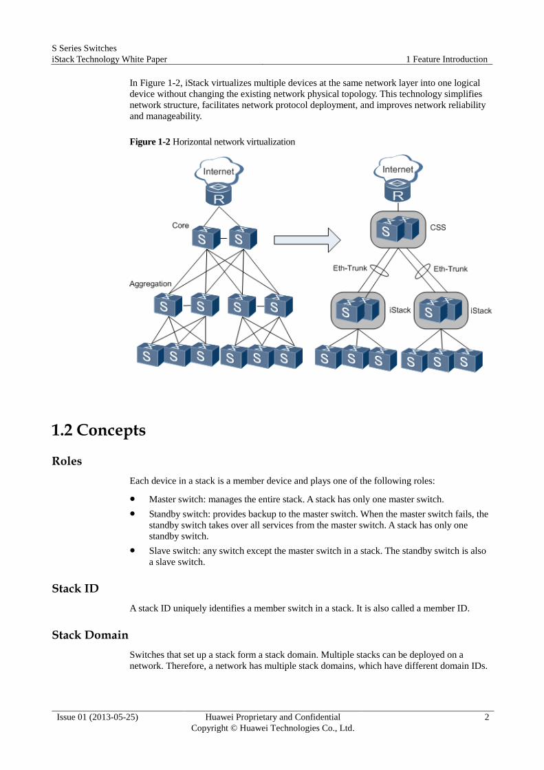
In Figure 1-2, iStack virtualizes multiple devices at the same network layer into one logical
device without changing the existing network physical topology. This technology simplifies
network structure, facilitates network protocol deployment, and improves network reliability
and manageability.
Figure 1-2 Horizontal network virtualization
1.2 Concepts
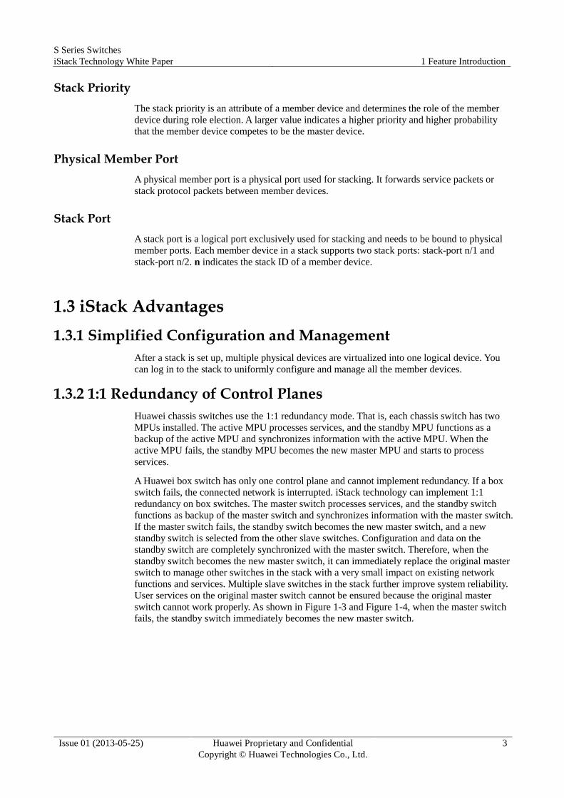
Roles
Each device in a stack is a member device and plays one of the following roles:
Master switch: manages the entire stack. A stack has only one master switch.
Standby switch: provides backup to the master switch. When the master switch fails, the
standby switch takes over all services from the master switch. A stack has only one
standby switch.
Slave switch: any switch except the master switch in a stack. The standby switch is also
a slave switch.
Stack ID
A stack ID uniquely identifies a member switch in a stack. It is also called a member ID.
Stack Domain
Switches that set up a stack form a stack domain. Multiple stacks can be deployed on a
network. Therefore, a network has multiple stack domains, which have different domain IDs.
S Series Switches
iStack Technology White Paper 1 Feature Introduction
Issue 01 (2013-05-25) Huawei Proprietary and Confidential
Copyright © Huawei Technologies Co., Ltd.
3
Stack Priority
The stack priority is an attribute of a member device and determines the role of the member
device during role election. A larger value indicates a higher priority and higher probability
that the member device competes to be the master device.
Physical Member Port
A physical member port is a physical port used for stacking. It forwards service packets or
stack protocol packets between member devices.
Stack Port
A stack port is a logical port exclusively used for stacking and needs to be bound to physical
member ports. Each member device in a stack supports two stack ports: stack-port n/1 and
stack-port n/2. n indicates the stack ID of a member device.
1.3 iStack Advantages
1.3.1 Simplified Configuration and Management
After a stack is set up, multiple physical devices are virtualized into one logical device. You
can log in to the stack to uniformly configure and manage all the member devices.
1.3.2 1:1 Redundancy of Control Planes
Huawei chassis switches use the 1:1 redundancy mode. That is, each chassis switch has two
MPUs installed. The active MPU processes services, and the standby MPU functions as a
backup of the active MPU and synchronizes information with the active MPU. When the
active MPU fails, the standby MPU becomes the new master MPU and starts to process
services.
A Huawei box switch has only one control plane and cannot implement redundancy. If a box
switch fails, the connected network is interrupted. iStack technology can implement 1:1
redundancy on box switches. The master switch processes services, and the standby switch
functions as backup of the master switch and synchronizes information with the master switch.
If the master switch fails, the standby switch becomes the new master switch, and a new
standby switch is selected from the other slave switches. Configuration and data on the
standby switch are completely synchronized with the master switch. Therefore, when the
standby switch becomes the new master switch, it can immediately replace the original master
switch to manage other switches in the stack with a very small impact on existing network
functions and services. Multiple slave switches in the stack further improve system reliability.
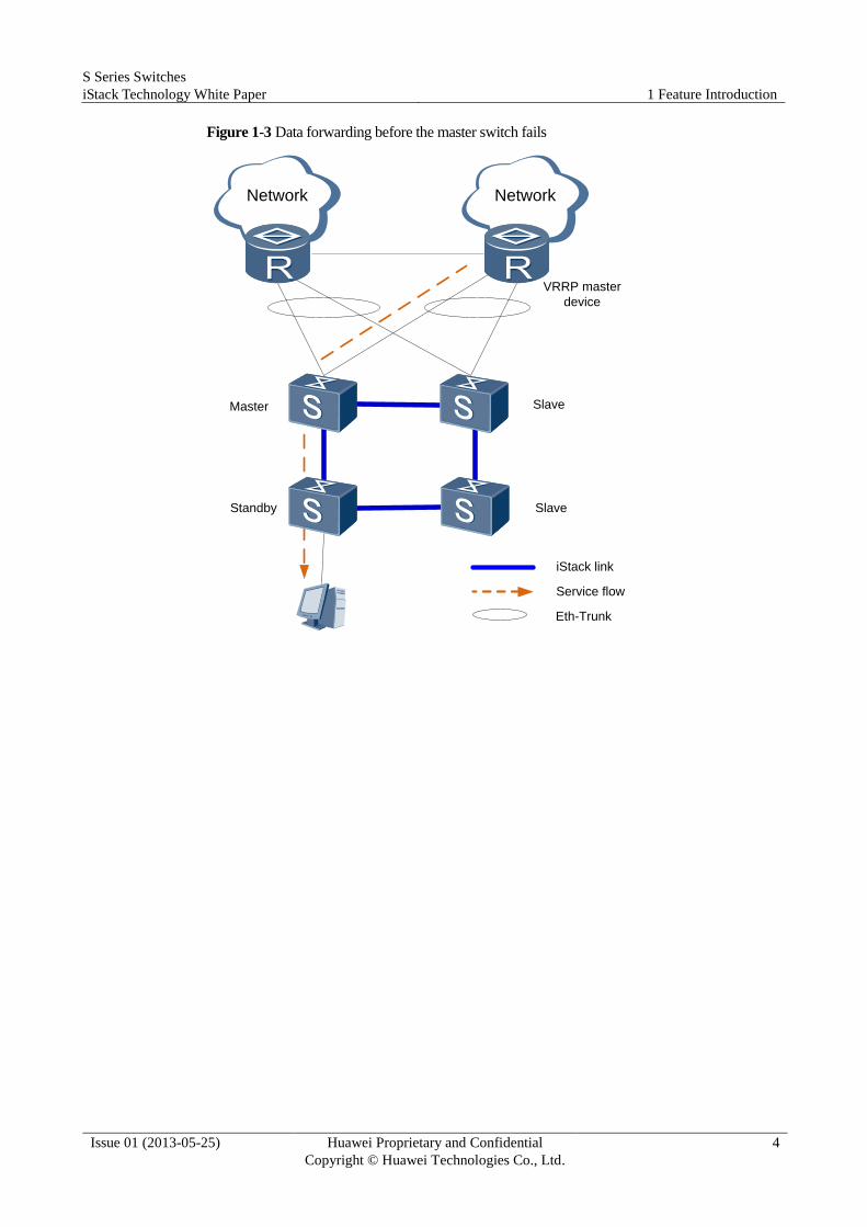
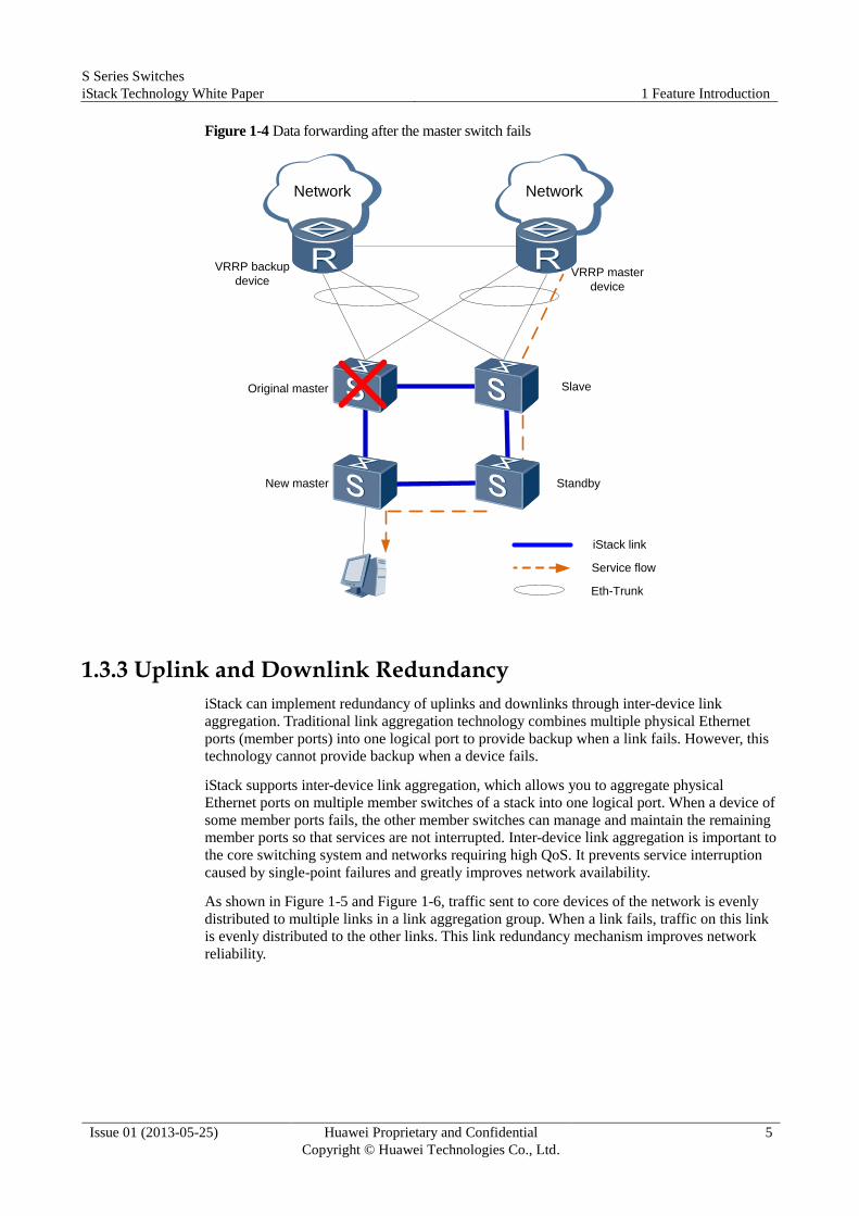
User services on the original master switch cannot be ensured because the original master
switch cannot work properly. As shown in Figure 1-3 and Figure 1-4, when the master switch
fails, the standby switch immediately becomes the new master switch.
S Series Switches
iStack Technology White Paper 1 Feature Introduction
Issue 01 (2013-05-25) Huawei Proprietary and Confidential
Copyright © Huawei Technologies Co., Ltd.
4
Figure 1-3 Data forwarding before the master switch fails
VRRP master
device
Master
Standby
Slave
Slave
Network Network
Eth-Trunk
iStack link
Service flow
S Series Switches
iStack Technology White Paper 1 Feature Introduction
Issue 01 (2013-05-25) Huawei Proprietary and Confidential
Copyright © Huawei Technologies Co., Ltd.
5
Figure 1-4 Data forwarding after the master switch fails
VRRP master
device
Original master
New master
Slave
Standby
Network Network
VRRP backup
device
Eth-Trunk
iStack link
Service flow
1.3.3 Uplink and Downlink Redundancy
iStack can implement redundancy of uplinks and downlinks through inter-device link
aggregation. Traditional link aggregation technology combines multiple physical Ethernet
ports (member ports) into one logical port to provide backup when a link fails. However, this
technology cannot provide backup when a device fails.
iStack supports inter-device link aggregation, which allows you to aggregate physical
Ethernet ports on multiple member switches of a stack into one logical port. When a device of
some member ports fails, the other member switches can manage and maintain the remaining
member ports so that services are not interrupted. Inter-device link aggregation is important to
the core switching system and networks requiring high QoS. It prevents service interruption
caused by single-point failures and greatly improves network availability.
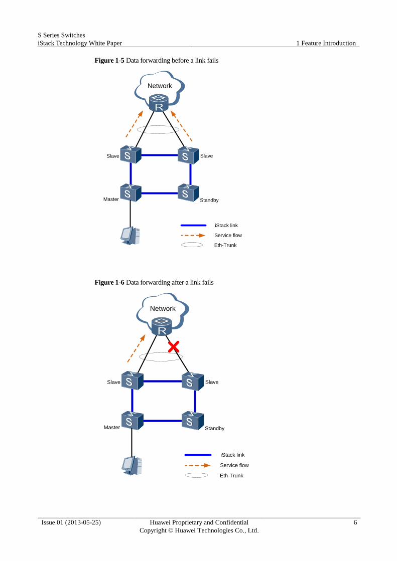
As shown in Figure 1-5 and Figure 1-6, traffic sent to core devices of the network is evenly
distributed to multiple links in a link aggregation group. When a link fails, traffic on this link
is evenly distributed to the other links. This link redundancy mechanism improves network
reliability.
S Series Switches
iStack Technology White Paper 1 Feature Introduction
Issue 01 (2013-05-25) Huawei Proprietary and Confidential
Copyright © Huawei Technologies Co., Ltd.
6
Figure 1-5 Data forwarding before a link fails
SlaveSlave
Master Standby
Eth-Trunk
iStack link
Service flow
Network
Figure 1-6 Data forwarding after a link fails
SlaveSlave
Master Standby
Eth-Trunk
iStack link
Service flow
Network
S Series Switches
iStack Technology White Paper 1 Feature Introduction
Issue 01 (2013-05-25) Huawei Proprietary and Confidential
Copyright © Huawei Technologies Co., Ltd.
7
1.3.4 Redundancy of Stack Links and Stack Ports
Redundancy of Stack Links in a Ring Topology
iStack can implement redundancy of stack links in a ring topology. When a link fails, the ring
topology changes into a chain topology so that services in the stack are not affected.
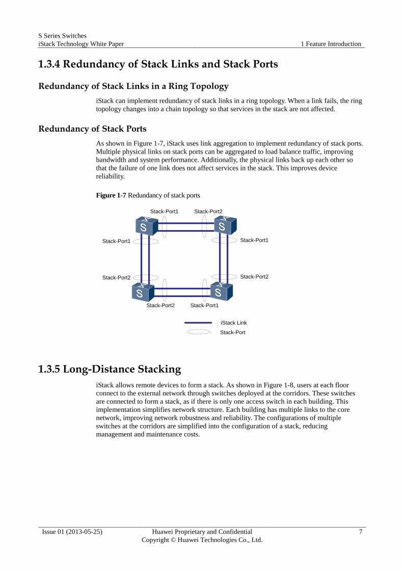
Redundancy of Stack Ports
As shown in Figure 1-7, iStack uses link aggregation to implement redundancy of stack ports.
Multiple physical links on stack ports can be aggregated to load balance traffic, improving
bandwidth and system performance. Additionally, the physical links back up each other so
that the failure of one link does not affect services in the stack. This improves device
reliability.
Figure 1-7 Redundancy of stack ports
Stack-Port1 Stack-Port2
Stack-Port2 Stack-Port1
Stack-Port1
Stack-Port2
Stack-Port1
Stack-Port2
Stack-Port
iStack Link
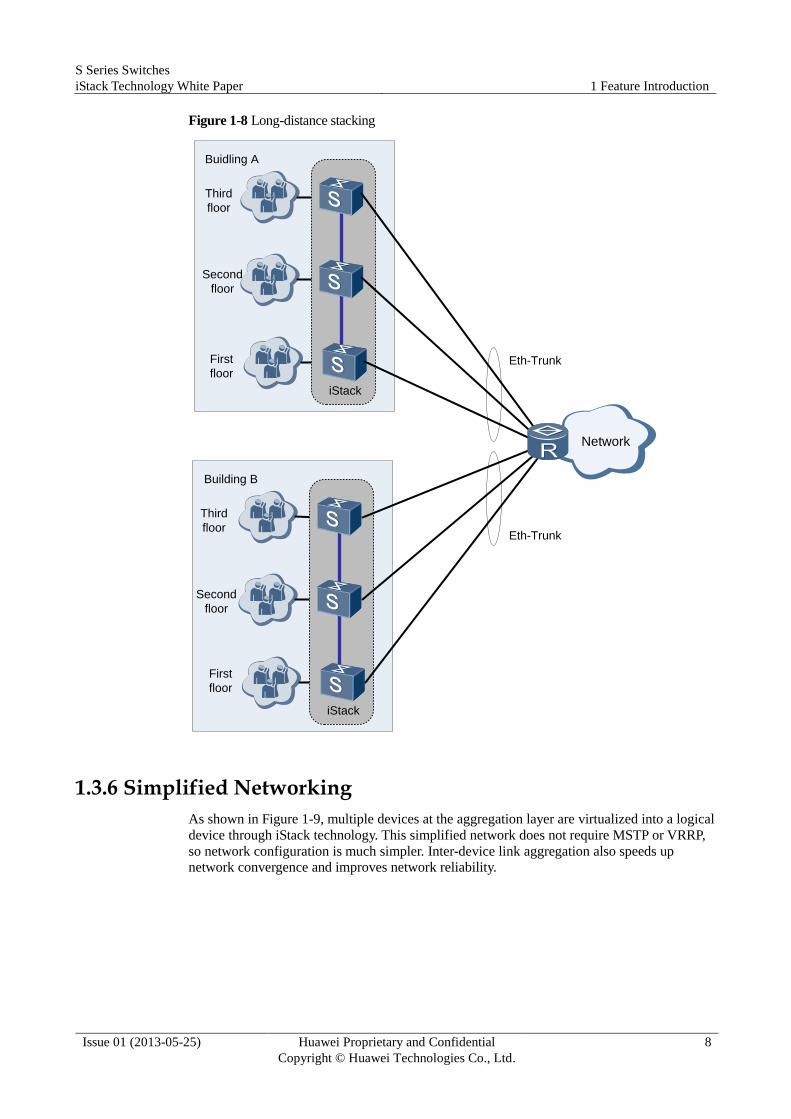
1.3.5 Long-Distance Stacking
iStack allows remote devices to form a stack. As shown in Figure 1-8, users at each floor
connect to the external network through switches deployed at the corridors. These switches
are connected to form a stack, as if there is only one access switch in each building. This
implementation simplifies network structure. Each building has multiple links to the core
network, improving network robustness and reliability. The configurations of multiple
switches at the corridors are simplified into the configuration of a stack, reducing
management and maintenance costs.
S Series Switches
iStack Technology White Paper 1 Feature Introduction
Issue 01 (2013-05-25) Huawei Proprietary and Confidential
Copyright © Huawei Technologies Co., Ltd.
8
Figure 1-8 Long-distance stacking
Building B
Third
floor
Second
floor
First
floor
Eth-Trunk
iStack
Buidling A
Third
floor
Second
floor
First
floor
iStack
Eth-Trunk
Network
1.3.6 Simplified Networking
As shown in Figure 1-9, multiple devices at the aggregation layer are virtualized into a logical
device through iStack technology. This simplified network does not require MSTP or VRRP,
so network configuration is much simpler. Inter-device link aggregation also speeds up
network convergence and improves network reliability.

S Series Switches
iStack Technology White Paper 1 Feature Introduction
Issue 01 (2013-05-25) Huawei Proprietary and Confidential
Copyright © Huawei Technologies Co., Ltd.
9
Figure 1-9 Simplified networking
MSTP +VRRP
iStack
Aggregation
Access
S Series Switches
iStack Technology White Paper 2 Technology Description
Issue 01 (2013-05-25) Huawei Proprietary and Confidential
Copyright © Huawei Technologies Co., Ltd.
10
2 Technology Description
2.1 Stack Physical Connection
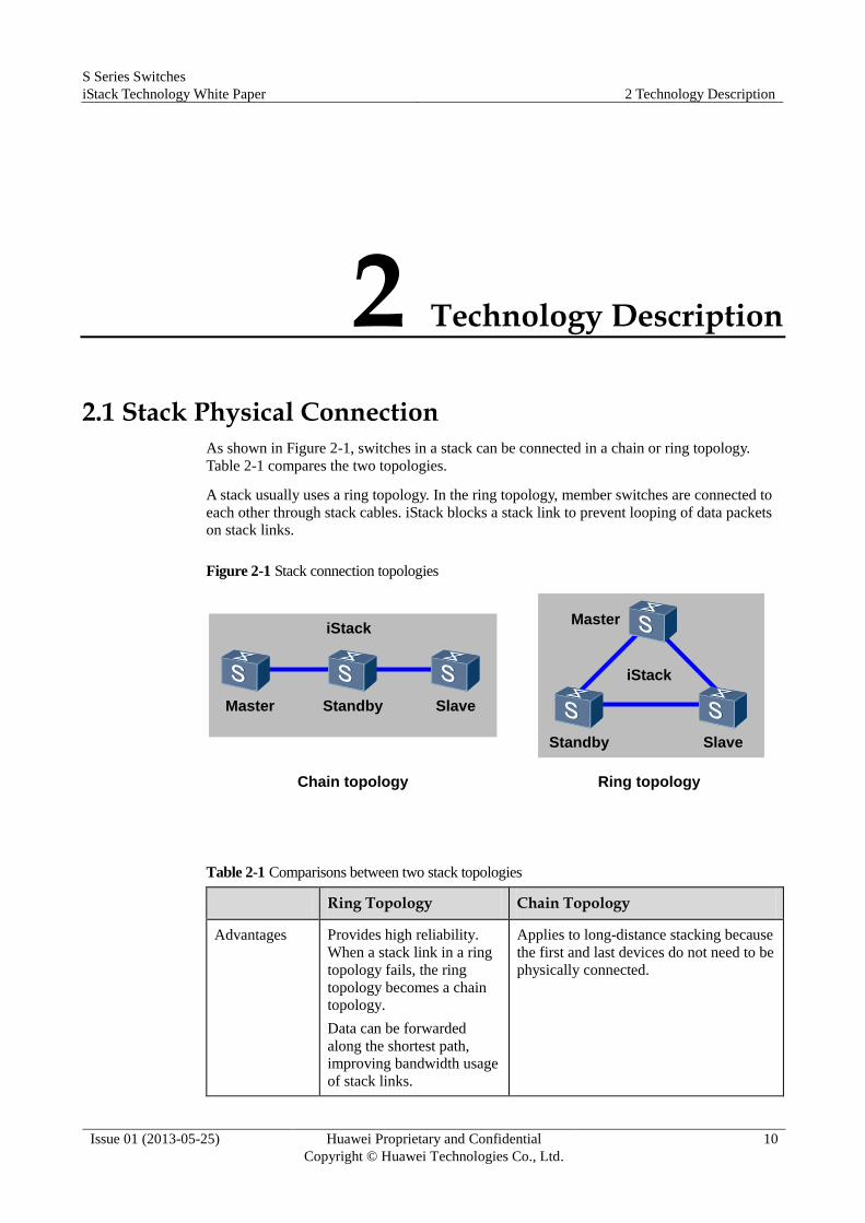
As shown in Figure 2-1, switches in a stack can be connected in a chain or ring topology.
Table 2-1 compares the two topologies.
A stack usually uses a ring topology. In the ring topology, member switches are connected to
each other through stack cables. iStack blocks a stack link to prevent looping of data packets
on stack links.
Figure 2-1 Stack connection topologies
Master SlaveStandby
Master
Standby Slave
Chain topology Ring topology
iStack
iStack
Table 2-1 Comparisons between two stack topologies
Ring Topology Chain Topology
Advantages Provides high reliability.
When a stack link in a ring
topology fails, the ring
topology becomes a chain
topology.
Data can be forwarded
along the shortest path,
improving bandwidth usage
of stack links.
Applies to long-distance stacking because
the first and last devices do not need to be
physically connected.

S Series Switches
iStack Technology White Paper 2 Technology Description
Issue 01 (2013-05-25) Huawei Proprietary and Confidential
Copyright © Huawei Technologies Co., Ltd.
11
Ring Topology Chain Topology
Disadvantages Does not apply to
long-distance stacking
because the member
devices need to be
physically connected to
each other.
Provides low reliability. When a stack
link fails, the stack cannot work properly
and some devices cannot work.
The entire stack has only one path,
reducing the stack link bandwidth usage.
Recommended
scenarios
To ensure reliability, the
ring topology is
recommended in scenarios
where the distance between
member devices is short.
The chain topology is recommended in
scenarios where the distance between
member devices is long because the ring
topology is difficult to deploy.
2.2 Stack Packets
The stack packet format varies slightly according to the version. The following uses the stack
packet format in V200R003 as an example.
2.2.1 Stack Packet Header
Table 2-2 Stack packet header
0 1 2 3 4 5 6 7 0 1 2 3 4 5 6 7 0 1 2 3 4 5 6 7 0 1 2 3 4 5 6 7
Dst MAC [4]
Dst MAC [2] Src MAC [2]
Src MAC [4]
VLAN Tag
EthType 0x5100 Version
ProtoType Resv
SrcFPort
SrcStackId
DesStackId
Length Resv
Packet Data
S Series Switches
iStack Technology White Paper 2 Technology Description
Issue 01 (2013-05-25) Huawei Proprietary and Confidential
Copyright © Huawei Technologies Co., Ltd.
12
Fields in the stack packet header are described as follows:
Dst Mac: destination MAC address.
SrcMac: source MAC address.
VLAN Tag: VLAN tag, which identifies the VLAN used in a stack. By default, a stack
uses VLAN 4093.
EthType: is fixed as 0x5100.
Version: is fixed as 1.
ProtoType: protocol type.
SrcFPort: source HIGIG port number.
SrcStackId: source stack ID.
DesStackId: destination stack ID.
Length: message length.
Resv: reservation state.
Packet Data: data packet.
2.2.2 Stack Packet Types
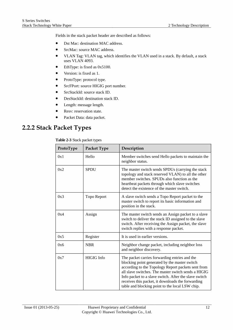
Table 2-3 Stack packet types
ProtoType Packet Type Description
0x1 Hello Member switches send Hello packets to maintain the
neighbor status.
0x2 SPDU The master switch sends SPDUs (carrying the stack
topology and stack reserved VLAN) to all the other
member switches. SPUDs also function as the
heartbeat packets through which slave switches
detect the existence of the master switch.
0x3 Topo Report A slave switch sends a Topo Report packet to the
master switch to report its basic information and
position in the stack.
0x4 Assign The master switch sends an Assign packet to a slave
switch to deliver the stack ID assigned to the slave
switch. After receiving the Assign packet, the slave
switch replies with a response packet.
0x5 Register It is used in earlier versions.
0x6 NBR Neighbor change packet, including neighbor loss
and neighbor discovery.
0x7 HIGIG Info The packet carries forwarding entries and the
blocking point generated by the master switch
according to the Topology Report packets sent from
all slave switches. The master switch sends a HIGIG
Info packet to a slave switch. After the slave switch
receives this packet, it downloads the forwarding
table and blocking point to the local LSW chip.
S Series Switches
iStack Technology White Paper 2 Technology Description
Issue 01 (2013-05-25) Huawei Proprietary and Confidential
Copyright © Huawei Technologies Co., Ltd.
13
ProtoType Packet Type Description
0x8 HeHuan Info It is not in use currently.
0x9 Modify Config Modifies the configuration.
0xa Load Loads the system software.
0xb Reset Resets a slave switch.
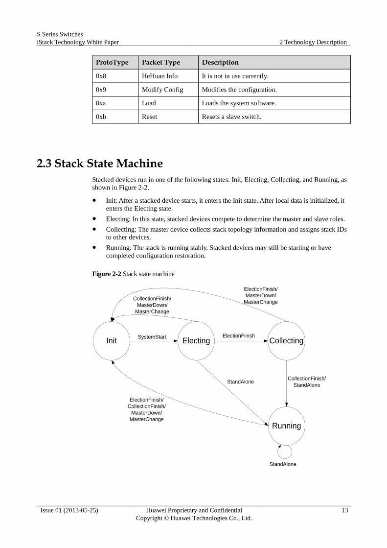
2.3 Stack State Machine
Stacked devices run in one of the following states: Init, Electing, Collecting, and Running, as
shown in Figure 2-2.
Init: After a stacked device starts, it enters the Init state. After local data is initialized, it
enters the Electing state.
Electing: In this state, stacked devices compete to determine the master and slave roles.
Collecting: The master device collects stack topology information and assigns stack IDs
to other devices.
Running: The stack is running stably. Stacked devices may still be starting or have
completed configuration restoration.
Figure 2-2 Stack state machine
Init Electing Collecting
Running
ElectionFinish
StandAlone
CollectionFinish/
MasterDown/
MasterChange
ElectionFinish/
MasterDown/
MasterChange
CollectionFinish/
StandAlone
ElectionFinish/
CollectionFinish/
MasterDown/
MasterChange
StandAlone
SystemStart
S Series Switches
iStack Technology White Paper 2 Technology Description
Issue 01 (2013-05-25) Huawei Proprietary and Confidential
Copyright © Huawei Technologies Co., Ltd.
14
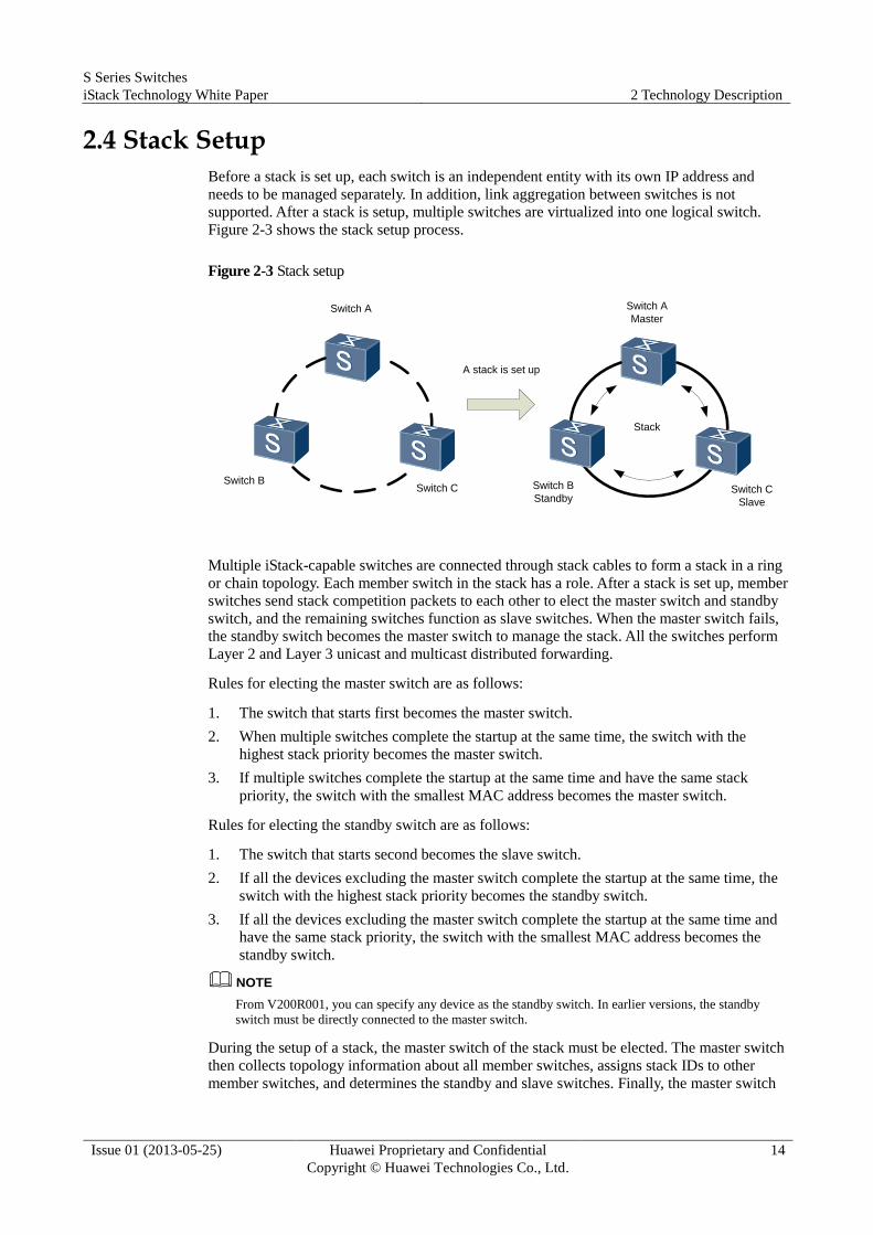
2.4 Stack Setup
Before a stack is set up, each switch is an independent entity with its own IP address and
needs to be managed separately. In addition, link aggregation between switches is not
supported. After a stack is setup, multiple switches are virtualized into one logical switch.
Figure 2-3 shows the stack setup process.
Figure 2-3 Stack setup
Switch A
Switch BSwitch C
Switch A
Master
Switch B
StandbySwitch C
Slave
A stack is set up
Stack
Multiple iStack-capable switches are connected through stack cables to form a stack in a ring
or chain topology. Each member switch in the stack has a role. After a stack is set up, member
switches send stack competition packets to each other to elect the master switch and standby
switch, and the remaining switches function as slave switches. When the master switch fails,
the standby switch becomes the master switch to manage the stack. All the switches perform
Layer 2 and Layer 3 unicast and multicast distributed forwarding.
Rules for electing the master switch are as follows:
1. The switch that starts first becomes the master switch.
2. When multiple switches complete the startup at the same time, the switch with the
highest stack priority becomes the master switch.
3. If multiple switches complete the startup at the same time and have the same stack
priority, the switch with the smallest MAC address becomes the master switch.
Rules for electing the standby switch are as follows:
1. The switch that starts second becomes the slave switch.
2. If all the devices excluding the master switch complete the startup at the same time, the
switch with the highest stack priority becomes the standby switch.
3. If all the devices excluding the master switch complete the startup at the same time and
have the same stack priority, the switch with the smallest MAC address becomes the
standby switch.
NOTE
From V200R001, you can specify any device as the standby switch. In earlier versions, the standby
switch must be directly connected to the master switch.
During the setup of a stack, the master switch of the stack must be elected. The master switch
then collects topology information about all member switches, assigns stack IDs to other
member switches, and determines the standby and slave switches. Finally, the master switch

S Series Switches
iStack Technology White Paper 2 Technology Description
Issue 01 (2013-05-25) Huawei Proprietary and Confidential
Copyright © Huawei Technologies Co., Ltd.
15
synchronizes the collected topology information, its own system software and configuration
file to other member switches and runs stably.
NOTE If the master and slave switches run different software versions, the slave switches synchronize the
software version with the master switch after a stack is set up.
Figure 2-4 Packet exchange during a stack setup
Electing state
SwitchA
(Master)
SwitchB
(Standby)
SwitchC
(Slave)
SPDUA
SPDU C
Receives SPDU
B, takes part in
stack competition,
and becomes the
master
Receives SPDU A and takes part in
stack competition. SwitchA
competes to be the master, and
SwitchB becomes the standby to
send an SPDU to its neighbor
Hello B
Receives
Hello packetsReceives Hello packets Receives Hello packets
Receives an SPDU and takes part
in stack competition. SwitchA
competes to be the master, and
SwitchC becomes the slave switch
Topo Report
Sends a Topo Report
packet to the master switch
Topo Report
Assign
Assign
Receives a Topo
Report packet and
assigns a stack ID
to SwitchBAssign ACK
Assign ACK
Sends a Topo Report
packet to the master switch
SPDU B
Hello A
SPDU B
Hello B
Hello C
Receives SPDU B and takes part in
stack competition. SwitchB
competes to be the master and
discards the SPDU because it has
no neighbors
Collecting state
Running state Running state Running state
SPDU A
Electing state Electing state
Collecting state Collecting state
Receives a Topo Report packet
and assigns a stack ID to SwitchC
2.5 Member Switch Addition
You can add a switch a stably running stack, as shown in Figure 2-5.

S Series Switches
iStack Technology White Paper 2 Technology Description
Issue 01 (2013-05-25) Huawei Proprietary and Confidential
Copyright © Huawei Technologies Co., Ltd.
16
A switch can be added to a stack after being powered off or with power on. In Figure 2-5, the
new member switch is powered off before being added to the stack.
Figure 2-5 Adding a member switch
SwitchA
Master
SwitchB
StandbySwitchC
Slave
SwitchD
+
SwitchA
Master
SwitchB
Standby
SwitchC
Slave
SwitchD
Slave
Add SwitchD to the stack
Stack
Stack
The process of adding a member switch is as follows:
The new switch is powered off, connected to the member switches of the stack through
stack cables, and restarted.
The new switch is elected as a slave switch after it starts, and roles of other member
switches in the stack remain unchanged.
After the election is complete, the master switch updates the topology information,
synchronizes the topology information to other switches, and assigns a stack ID to the
new member switch.
The new member switch updates its stack ID, registers with the master switch,
synchronizes the configuration with the master switch, and then enters the Running state.
Figure 2-6 shows how member switches exchange stack packets when a new member switch
is added to the stack.

S Series Switches
iStack Technology White Paper 2 Technology Description
Issue 01 (2013-05-25) Huawei Proprietary and Confidential
Copyright © Huawei Technologies Co., Ltd.
17
Figure 2-6 Packet exchange during the addition of a member switch
SwitchA
(Master)
SwitchB
(Standby)
SwitchC
(Slave)
NBR Discover
Receives a Hello packet Receives a Hello packet
Sends a Topo Report
packet to the master switch
Topo Report
Assign
Receives a
Topo Report
packet and
assigns a
stack ID to
SwitchC
Assign ACK
Hello B
SPDU C
Receives an SPUD and takes part
in stack competition. SwitchA
competes to be the master and
SwitchC becomes a slave switch
SwitchA does
not process
the packet
because
SwitchC joins
the stack for
the first time
and SwitchA
has no
information
about SwitchC
SwitchC fails in stack
competition and its
SPDU is discarded
Newly added
Periodically sends SPDUs
Electing state
Collecting state
Running stateRunning state Running state
Hello C
SPDU A
SPDU A
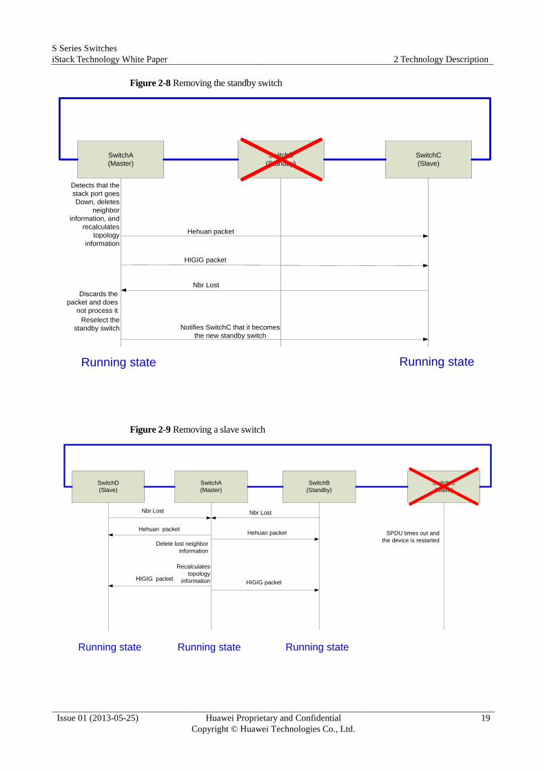
2.6 Member Switch Removal
You can remove a member switch from a stack. The stack is affected in the following ways
after a member switch is removed:
If the master switch is removed, the neighbor switch notifies other member switches of
the topology change and updates local neighbor information. The standby switch
becomes the new master switch. It recalculates the topology information, synchronizes
the information to other members, and selects the new standby switch. Then the stack
enters running state.
When the standby switch is removed, the master switch specifies a new standby switch,
and then recalculates the stack topology and synchronizes the information to other
member switches.
When a slave switch is removed, the master switch recalculates the stack topology
information and synchronizes the information to other member switches.

S Series Switches
iStack Technology White Paper 2 Technology Description
Issue 01 (2013-05-25) Huawei Proprietary and Confidential
Copyright © Huawei Technologies Co., Ltd.
18
Figure 2-7, Figure 2-8, and Figure 2-9 illustrate stack packet exchange during the removal of
the master switch, standby switch, and slave switch respectively.
Figure 2-7 Removing the master switch
SwitchA
(Master)SwitchB
(StandBy)
SwitchC
(Slave)
Hehuan packet
Reselect the standby switch
Detects that the stack port goes
Down, deletes neighbor information,
and becomes the new master switch
SPDU
Notifies SwitchC that it is the new
standby switch
HIGIG packet
Nbr Lost
S Series Switches
iStack Technology White Paper 2 Technology Description
Issue 01 (2013-05-25) Huawei Proprietary and Confidential
Copyright © Huawei Technologies Co., Ltd.
19
Figure 2-8 Removing the standby switch
SwitchA
(Master)
SwitchB
(Standby)
SwitchC
(Slave)
Detects that the
stack port goes
Down, deletes
neighbor
information, and
recalculates
topology
information
Hehuan packet
HIGIG packet
Nbr Lost
Discards the
packet and does
not process it
Notifies SwitchC that it becomes
the new standby switch
Reselect the
standby switch
Running state Running state
Figure 2-9 Removing a slave switch
SwitchA
(Master)
SwitchB
(Standby)
Switch C
(Slave)
Nbr Lost
SPDU times out and
the device is restartedDelete lost neighbor
information
Hehuan packet
Recalculates
topology
informationHIGIG packet
SwitchD
(Slave)
Nbr Lost
Running state Running state Running state
Hehuan packet
HIGIG packet

S Series Switches
iStack Technology White Paper 2 Technology Description
Issue 01 (2013-05-25) Huawei Proprietary and Confidential
Copyright © Huawei Technologies Co., Ltd.
20
2.7 Stack Merge
As shown in Figure 2-10, two stable stacks are merged into one stack. The superior switch
between the master switches of the two stacks is selected as the master switch of the new
stack. The original stack containing the new master remains the original device roles and
configurations, and services in this stack are not affected. Switches in the other stack restart
and join the new stack as slave switches. Then the master switch assigns new stack IDs to the
restarted switches and synchronizes configurations to the switches. Services on these switches
are interrupted in this period.
Figure 2-10 Stack merge
SwitchA
Master
SwitchC
Slave
SwitchA
Master
SwitchB
StandbySwitchC
Slave
SwitchD
Slave
Stack merge
Stack1
SwitchB
Standby
SwitchD
Master
SwitchE
Slave
Stack2
SwitchE
Slave
Stack1
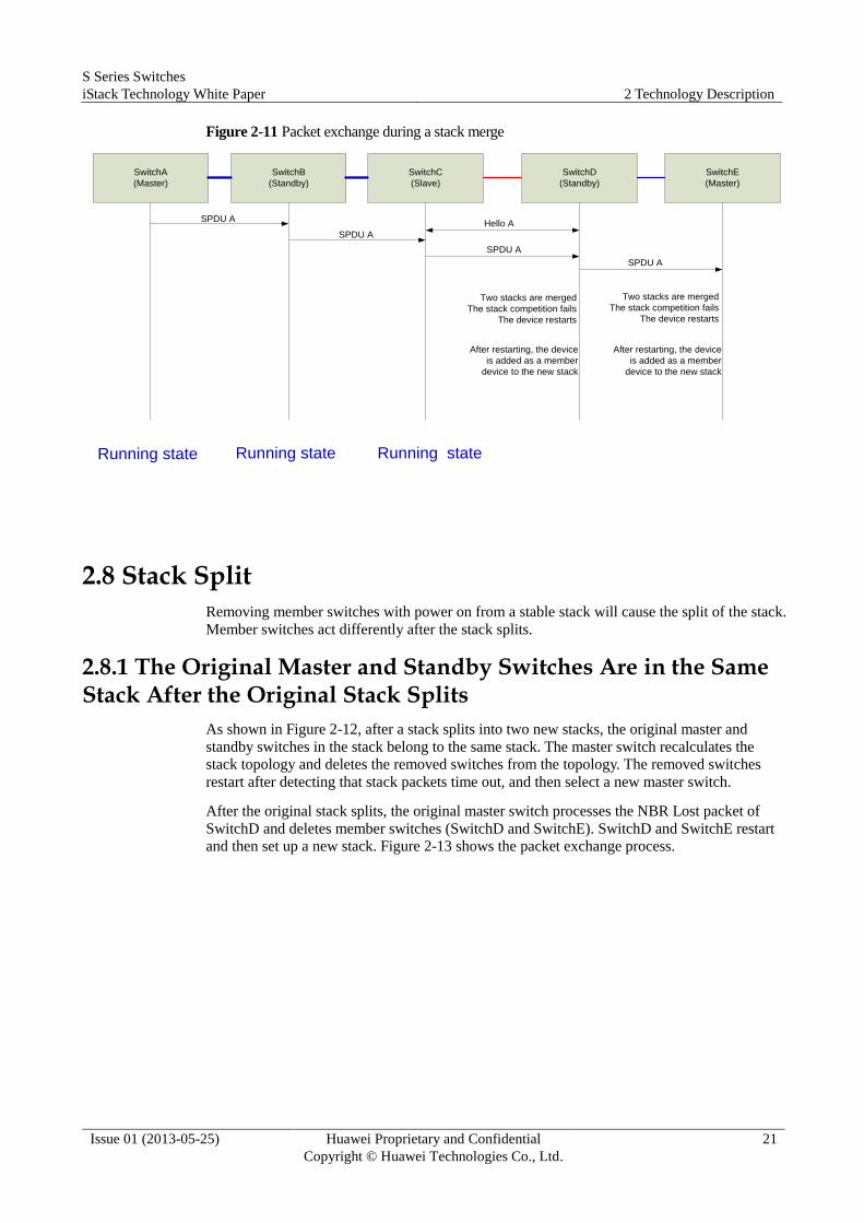
The process of merging two stacks is similar to the process of adding a member switch as
shown in Figure 2-11. The master switches of the original two stacks compete the master of
the new stack. Member switches in the stack whose master switch fails the master competition
join the new stack. For details, see the process of adding a member switch.
S Series Switches
iStack Technology White Paper 2 Technology Description
Issue 01 (2013-05-25) Huawei Proprietary and Confidential
Copyright © Huawei Technologies Co., Ltd.
21
Figure 2-11 Packet exchange during a stack merge
SwitchA
(Master)
SwitchB
(Standby)
SwitchC
(Slave)
Running state Running stateRunning state
SwitchD
(Standby)
SwitchE
(Master)
SPDU A
SPDU A
SPDU A
SPDU A
Hello A
Two stacks are merged
The stack competition fails
The device restarts
After restarting, the device
is added as a member
device to the new stack
Two stacks are merged
The stack competition fails
The device restarts
After restarting, the device
is added as a member
device to the new stack
2.8 Stack Split
Removing member switches with power on from a stable stack will cause the split of the stack.
Member switches act differently after the stack splits.
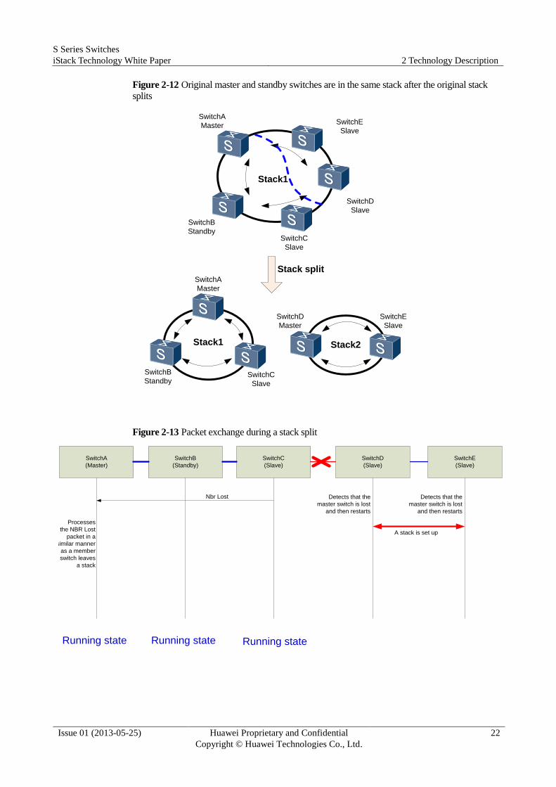
2.8.1 The Original Master and Standby Switches Are in the Same Stack After the Original Stack Splits
As shown in Figure 2-12, after a stack splits into two new stacks, the original master and
standby switches in the stack belong to the same stack. The master switch recalculates the
stack topology and deletes the removed switches from the topology. The removed switches
restart after detecting that stack packets time out, and then select a new master switch.
After the original stack splits, the original master switch processes the NBR Lost packet of
SwitchD and deletes member switches (SwitchD and SwitchE). SwitchD and SwitchE restart
and then set up a new stack. Figure 2-13 shows the packet exchange process.
S Series Switches
iStack Technology White Paper 2 Technology Description
Issue 01 (2013-05-25) Huawei Proprietary and Confidential
Copyright © Huawei Technologies Co., Ltd.
22
Figure 2-12 Original master and standby switches are in the same stack after the original stack
splits
SwitchA
Master
SwitchC
Slave
SwitchA
Master
SwitchB
StandbySwitchC
Slave
SwitchD
Slave
Stack split
Stack1
SwitchB
Standby
SwitchD
Master
SwitchE
Slave
Stack2
SwitchE
Slave
Stack1
Figure 2-13 Packet exchange during a stack split
SwitchA
(Master)
SwitchB
(Standby)
SwitchC
(Slave)
Running state Running stateRunning state
SwitchD
(Slave)
SwitchE
(Slave)
Detects that the
master switch is lost
and then restarts
Detects that the
master switch is lost
and then restarts
Nbr Lost
Processes
the NBR Lost
packet in a
similar manner
as a member
switch leaves
a stack
A stack is set up

S Series Switches
iStack Technology White Paper 2 Technology Description
Issue 01 (2013-05-25) Huawei Proprietary and Confidential
Copyright © Huawei Technologies Co., Ltd.
23
2.8.2 The Original Master and Standby Switches Are in Different Stacks After the Original Stack Splits
As shown in Figure 2-14, after a stack splits into two new stacks, the original master and
standby switches in the stack belong to two different stacks. The master switch specifies a
new standby switch, recalculates the stack topology information, and synchronizes the
information to other member switches as shown in Figure 2-8. The original standby switch
becomes the master switch of the other stack, recalculates the stack topology information, and
synchronizes the information to other member switches as shown in Figure 2-7. Figure 2-15
shows the packet exchange process.
Figure 2-14 Original master and standby switches are in different stacks after the original stack
splits
SwitchA
Master
SwitchE
Slave
SwitchA
Master
SwitchB
StandbySwitchC
Slave
SwitchD
Slave
Stack split
Stack1
SwitchD
Standby
SwitchB
Master
SwitchC
Slave
Stack2
SwitchE
Slave
Stack1
S Series Switches
iStack Technology White Paper 2 Technology Description
Issue 01 (2013-05-25) Huawei Proprietary and Confidential
Copyright © Huawei Technologies Co., Ltd.
24
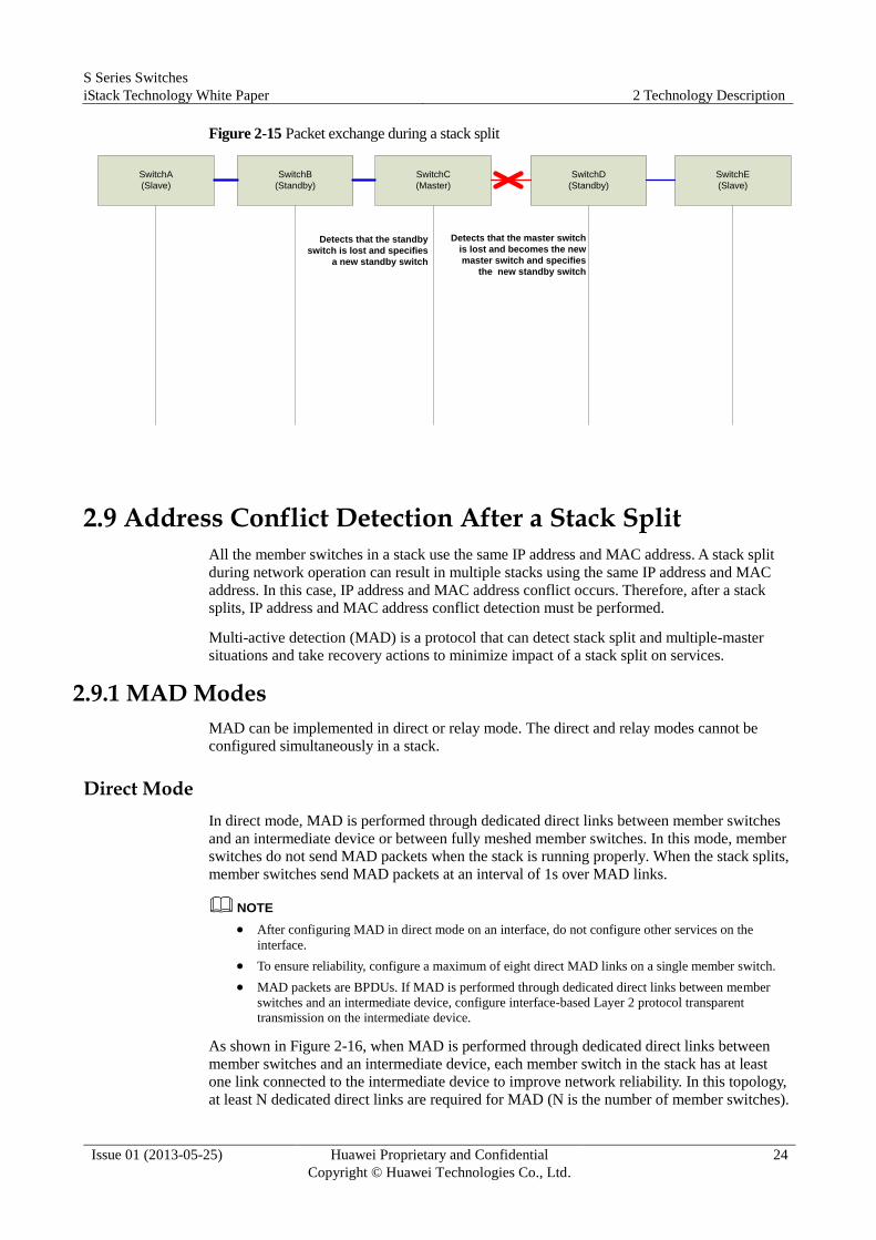
Figure 2-15 Packet exchange during a stack split
SwitchA
(Slave)
SwitchB
(Standby)
SwitchC
(Master)
SwitchD
(Standby)
SwitchE
(Slave)
Detects that the standby
switch is lost and specifies
a new standby switch
Detects that the master switch
is lost and becomes the new
master switch and specifies
the new standby switch
2.9 Address Conflict Detection After a Stack Split
All the member switches in a stack use the same IP address and MAC address. A stack split
during network operation can result in multiple stacks using the same IP address and MAC
address. In this case, IP address and MAC address conflict occurs. Therefore, after a stack
splits, IP address and MAC address conflict detection must be performed.
Multi-active detection (MAD) is a protocol that can detect stack split and multiple-master
situations and take recovery actions to minimize impact of a stack split on services.
2.9.1 MAD Modes
MAD can be implemented in direct or relay mode. The direct and relay modes cannot be
configured simultaneously in a stack.
Direct Mode
In direct mode, MAD is performed through dedicated direct links between member switches
and an intermediate device or between fully meshed member switches. In this mode, member
switches do not send MAD packets when the stack is running properly. When the stack splits,
member switches send MAD packets at an interval of 1s over MAD links.
NOTE
After configuring MAD in direct mode on an interface, do not configure other services on the
interface.
To ensure reliability, configure a maximum of eight direct MAD links on a single member switch.
MAD packets are BPDUs. If MAD is performed through dedicated direct links between member
switches and an intermediate device, configure interface-based Layer 2 protocol transparent
transmission on the intermediate device.
As shown in Figure 2-16, when MAD is performed through dedicated direct links between
member switches and an intermediate device, each member switch in the stack has at least
one link connected to the intermediate device to improve network reliability. In this topology,
at least N dedicated direct links are required for MAD (N is the number of member switches).

S Series Switches
iStack Technology White Paper 2 Technology Description
Issue 01 (2013-05-25) Huawei Proprietary and Confidential
Copyright © Huawei Technologies Co., Ltd.
25
As shown in Figure 2-17, member switches in the stack are fully meshed to improve
reliability. No intermediate device is deployed in this topology so that MAD will not be
affected by failures of the intermediate device. The full-mesh topology requires at least
½N(N-1) dedicated direct links for MAD (N is the number of member switches).
Figure 2-16 MAD through direct links to an intermediate device
SwitchA SwitchB
iStack
MAD link
iStack link
SwitchC
SwitchD
Figure 2-17 MAD through direct links between fully meshed member switches
SwitchA SwitchB
iStack
MAD link
iStack link
SwitchC
Relay Mode
In relay mode, MAD relay detection is configured on inter-device Eth-Trunk interfaces, and
the MAD relay function is enabled on an agent. This MAD mode requires that all the member
switches in the stack have links to the MAD relay agent and these links be added to the same
Eth-Trunk. The relay mode does not require additional interfaces because Eth-Trunk
interfaces can perform MAD relay detection and run other services simultaneously.
In relay mode, member switches send MAD packets at an interval of 30s over MAD links
when the stack is running properly. When the stack is running properly, member switches do
not process received MAD packets. After the stack splits, member switches send MAD
packets over MAD links at an interval of 1s.

S Series Switches
iStack Technology White Paper 2 Technology Description
Issue 01 (2013-05-25) Huawei Proprietary and Confidential
Copyright © Huawei Technologies Co., Ltd.
26
The relay mode can be implemented in two ways: single switch as the MAD relay agent and
two stacks as MAD relay agents of each other.
NOTE The MAD relay agent is a switch that supports the MAD relay function. Currently,
S2750&S5700&S6700 series switches support this function.
Two stacks can function as a proxy of each other to implement MAD. The two stacks must be
configured with different MAD domain IDs.
Figure 2-18 Single switch as the MAD relay agent
SwitchA SwitchB
iStack
MAD link
iStack link
SwitchC
SwitchD
Eth-Trunk
Figure 2-19 Two stacks as MAD relay agents of each other
SwitchD SwitchEiStack
MAD link
iStack link
SwitchF
Eth-Trunk
SwitchA SwitchBiStack
SwitchCDomain ID 1
Domain ID 2

S Series Switches
iStack Technology White Paper 2 Technology Description
Issue 01 (2013-05-25) Huawei Proprietary and Confidential
Copyright © Huawei Technologies Co., Ltd.
27
To ensure reliability, configure the relay mode on a maximum of four Eth-Trunks in a stack.
Each Eth-Trunk can have a maximum eight member interfaces. Therefore, when a stack
contains nine member switches, one Eth-Trunk cannot provide detection links for all the
member switches. In this case, multiple Eth-Trunks need to be configured to ensure that a
detection link is available between any two member switches. As shown in Figure 2-20,
Eth-Trunk1 provides detection links for Switch1 to Switch8, Eth-Trunk2 provides detection
links for Switch2 to Switch9, and Eth-Trunk3 provides detection links for Switch1 and
Switch9.
Figure 2-20 MAD relay detection on multiple Eth-Trunks
Eth-Trunk2
MAD link
iStack link
Eth-Trunk1
Eth-Trunk3
Eth-Trunk3
iStack
Switch1 Switch2 Switch8 Switch9
2.9.2 MAD Collision Handling
After a stack splits, the MAD split detection mechanism detects multiple stacks in Active state
(indicating that the stacks are working normally). Then the MAD collision handling
mechanism retains the stack with the original master switch in Active state and turns the other
stacks into Recovery state (stacks do not work in this state). Member switches in the stacks in
Recovery state shut down all their physical ports (generally service ports) except reserved
ports, so that these stacks do not forward service packets. By default, only physical member
ports of stack ports are reserved ports. You can run a command to specify other ports, such as
the port used for remote login, as reserved ports.
2.9.3 MAD Fault Recovery
After a fault link recovers, the MAD fault recovery mechanism merges the stacks into one.
Stacks can merge in either of the following ways:
After the fault link recovers, the stacks in Recovery state restart and merge with the stack
in Active state, and restore the shutdown service ports to Up state. Then the entire stack
recovers.
If the stack in Active state is also faulty before the faulty link recovers, remove the stack
in Active state first, and use a command to start the stacks in Recovery state, enabling the
stacks to take over services on the original stack in Active state. After the original stack
in Active state and the faulty link recover, the stacks can merge.
S Series Switches
iStack Technology White Paper 2 Technology Description
Issue 01 (2013-05-25) Huawei Proprietary and Confidential
Copyright © Huawei Technologies Co., Ltd.
28
2.10 Automatic Software Upgrade of Member Switches
iStack has automatic system software load function. A new member switch can join a stack if
its software version is compatible with that of the stack. When you add the new member
switch to the stack, the new member switch compares its software version with that of the
stack. If the software versions are inconsistent, the new member switch downloads the system
startup file from the master switch, restarts using the new startup file, and joins the stack. If
the new member switch has a software version that is incompatible with that of the stack,
ensure that the new member switch has the same software version as the existing member
switches. Then the new member switch can join the stack.
NOTE When multiple member switches are added to a stack simultaneously, the software versions of these
switches are automatically upgraded one by one.
2.11 Smooth Upgrade
A stack is usually upgraded by specifying the startup system software and restarting the stack.
However, this upgrade method causes service interruption in a long time. If uplinks and
downlinks of a stack work in redundancy mode, as shown in Figure 2-21, you can perform a
smooth upgrade in the stack to shorten the upgrade time and reduce impact of the upgrade on
running services.
S Series Switches
iStack Technology White Paper 2 Technology Description
Issue 01 (2013-05-25) Huawei Proprietary and Confidential
Copyright © Huawei Technologies Co., Ltd.
29
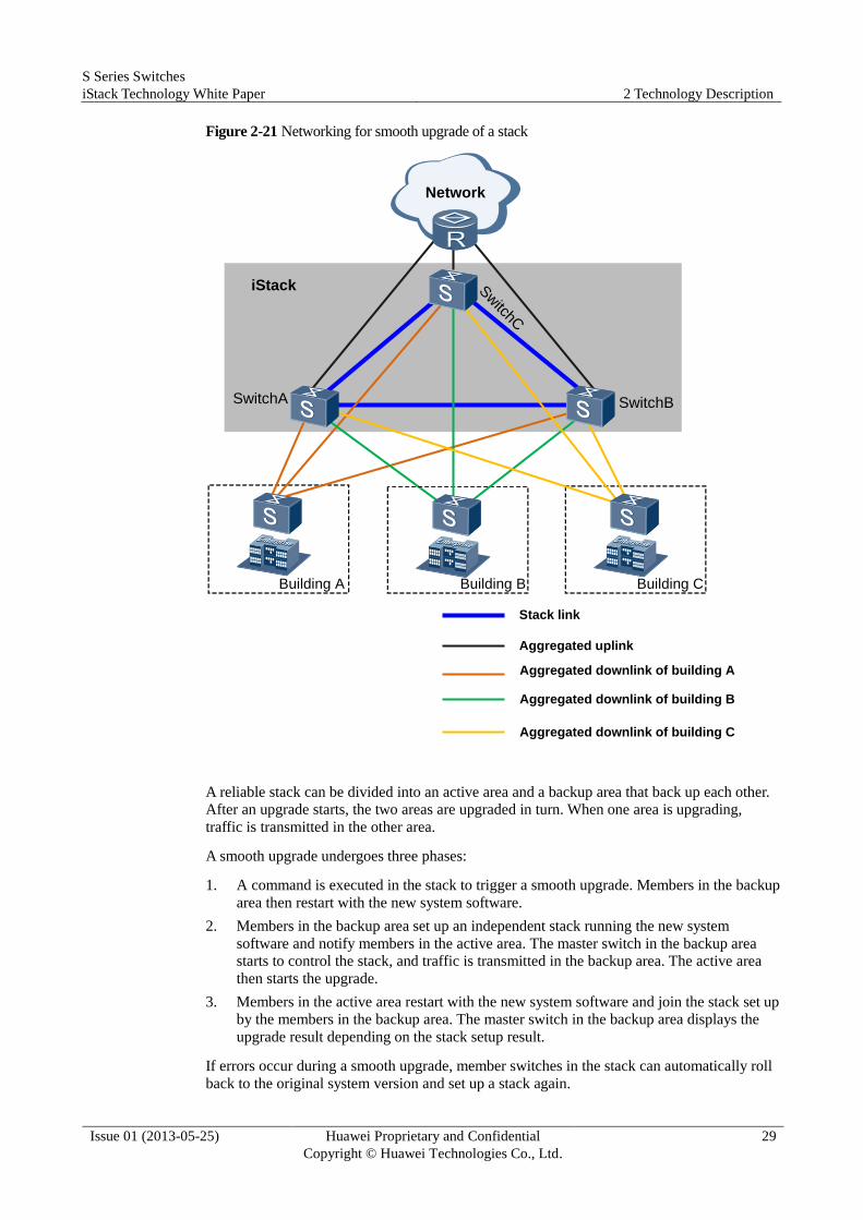
Figure 2-21 Networking for smooth upgrade of a stack
Network
SwitchA SwitchB
SwitchC
Stack link
Aggregated uplink
iStack
Building A Building B Building C
Aggregated downlink of building A
Aggregated downlink of building B
Aggregated downlink of building C
A reliable stack can be divided into an active area and a backup area that back up each other.
After an upgrade starts, the two areas are upgraded in turn. When one area is upgrading,
traffic is transmitted in the other area.
A smooth upgrade undergoes three phases:
1. A command is executed in the stack to trigger a smooth upgrade. Members in the backup
area then restart with the new system software.
2. Members in the backup area set up an independent stack running the new system
software and notify members in the active area. The master switch in the backup area
starts to control the stack, and traffic is transmitted in the backup area. The active area
then starts the upgrade.
3. Members in the active area restart with the new system software and join the stack set up
by the members in the backup area. The master switch in the backup area displays the
upgrade result depending on the stack setup result.
If errors occur during a smooth upgrade, member switches in the stack can automatically roll
back to the original system version and set up a stack again.
S Series Switches
iStack Technology White Paper 2 Technology Description
Issue 01 (2013-05-25) Huawei Proprietary and Confidential
Copyright © Huawei Technologies Co., Ltd.
30
2.12 iStack Packet Forwarding
2.12.1 Unicast Packet Forwarding
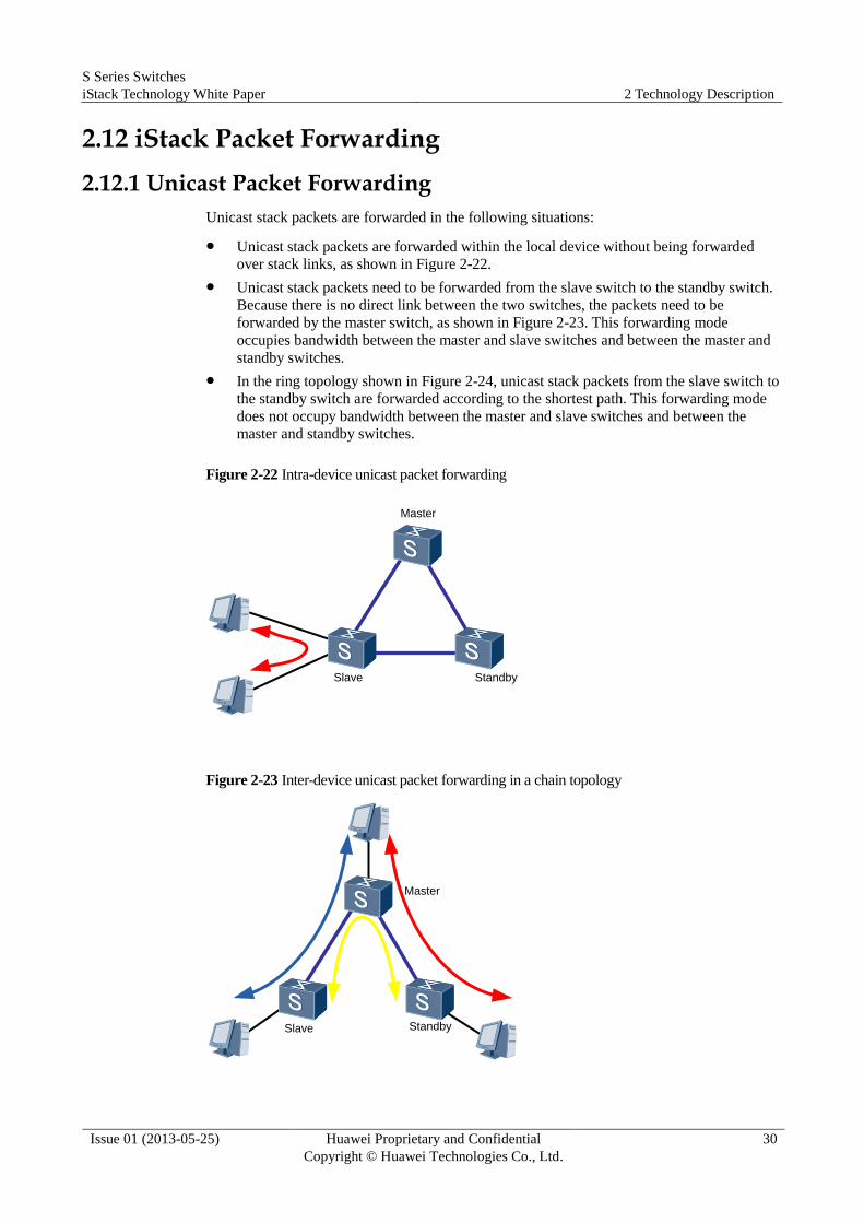
Unicast stack packets are forwarded in the following situations:
Unicast stack packets are forwarded within the local device without being forwarded
over stack links, as shown in Figure 2-22.
Unicast stack packets need to be forwarded from the slave switch to the standby switch.
Because there is no direct link between the two switches, the packets need to be
forwarded by the master switch, as shown in Figure 2-23. This forwarding mode
occupies bandwidth between the master and slave switches and between the master and
standby switches.
In the ring topology shown in Figure 2-24, unicast stack packets from the slave switch to
the standby switch are forwarded according to the shortest path. This forwarding mode
does not occupy bandwidth between the master and slave switches and between the
master and standby switches.
Figure 2-22 Intra-device unicast packet forwarding
Master
Slave Standby
Figure 2-23 Inter-device unicast packet forwarding in a chain topology
Master
Slave Standby

S Series Switches
iStack Technology White Paper 2 Technology Description
Issue 01 (2013-05-25) Huawei Proprietary and Confidential
Copyright © Huawei Technologies Co., Ltd.
31
Figure 2-24 Inter-device unicast packet forwarding in a ring topology
Master
Slave Standby
2.12.2 Unknown Unicast and Broadcast Packet Forwarding
In a ring topology, broadcast packets will not be looped within a stack because the stack has
only one path. In a ring topology, loop prevention needs to be performed to prevent broadcast
packets from being looped between devices. The following describes how to prevent loops
when an even or odd number of member devices are deployed in a ring topology.
Loop Prevention in the Case of an Odd Number of Member Switches
In versions earlier than V200R001, the link farthest from the master switch is blocked to
prevent loops, as shown in Figure 2-25.
Figure 2-25 Broadcast packet forwarding in V100R006 and earlier versions
Slave
Master
Standby
Slave
Slave
In versions earlier than V200R001, two users farther from the master need to communicate
and their data needs to be forwarded through stack cables of five member switches, as shown
in Figure 2-25. This forwarding mode wastes bandwidth of intermediate stack links.
S Series Switches
iStack Technology White Paper 2 Technology Description
Issue 01 (2013-05-25) Huawei Proprietary and Confidential
Copyright © Huawei Technologies Co., Ltd.
32
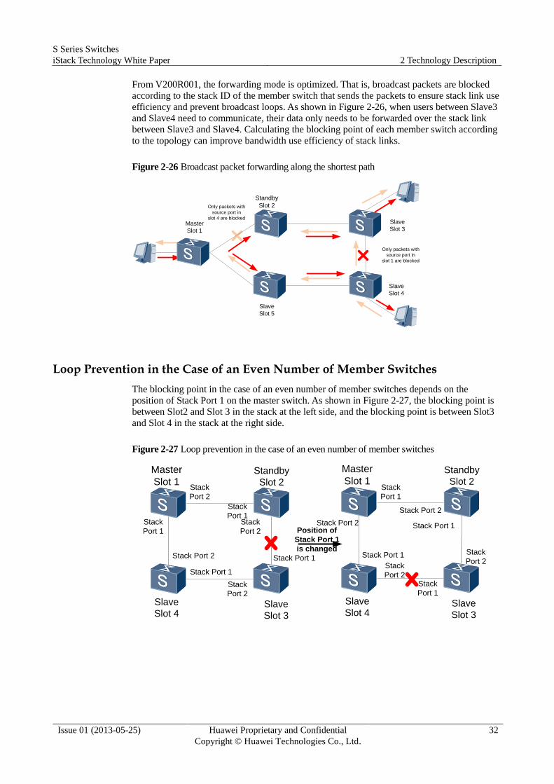
From V200R001, the forwarding mode is optimized. That is, broadcast packets are blocked
according to the stack ID of the member switch that sends the packets to ensure stack link use
efficiency and prevent broadcast loops. As shown in Figure 2-26, when users between Slave3
and Slave4 need to communicate, their data only needs to be forwarded over the stack link
between Slave3 and Slave4. Calculating the blocking point of each member switch according
to the topology can improve bandwidth use efficiency of stack links.
Figure 2-26 Broadcast packet forwarding along the shortest path
Slave
Slot 5
Master
Slot 1
Standby
Slot 2
Slave
Slot 3
Slave
Slot 4
Only packets with
source port in
slot 1 are blocked
Only packets with
source port in
slot 4 are blocked
Loop Prevention in the Case of an Even Number of Member Switches
The blocking point in the case of an even number of member switches depends on the
position of Stack Port 1 on the master switch. As shown in Figure 2-27, the blocking point is
between Slot2 and Slot 3 in the stack at the left side, and the blocking point is between Slot3
and Slot 4 in the stack at the right side.
Figure 2-27 Loop prevention in the case of an even number of member switches
Slave
Slot 4
Master
Slot 1
Slave
Slot 3
Standby
Slot 2Stack
Port 2
Stack
Port 1Stack
Port 2
Stack
Port 2
Stack Port 2 Stack Port 1
Stack Port 1
Stack
Port 1
Slave
Slot 4
Master
Slot 1
Slave
Slot 3
Standby
Slot 2Stack
Port 1
Stack Port 2
Stack Port 1
Stack
Port 1
Stack Port 1 Stack
Port 2Stack
Port 2
Stack Port 2Position of
Stack Port 1
is changed
S Series Switches
iStack Technology White Paper 2 Technology Description
Issue 01 (2013-05-25) Huawei Proprietary and Confidential
Copyright © Huawei Technologies Co., Ltd.
33
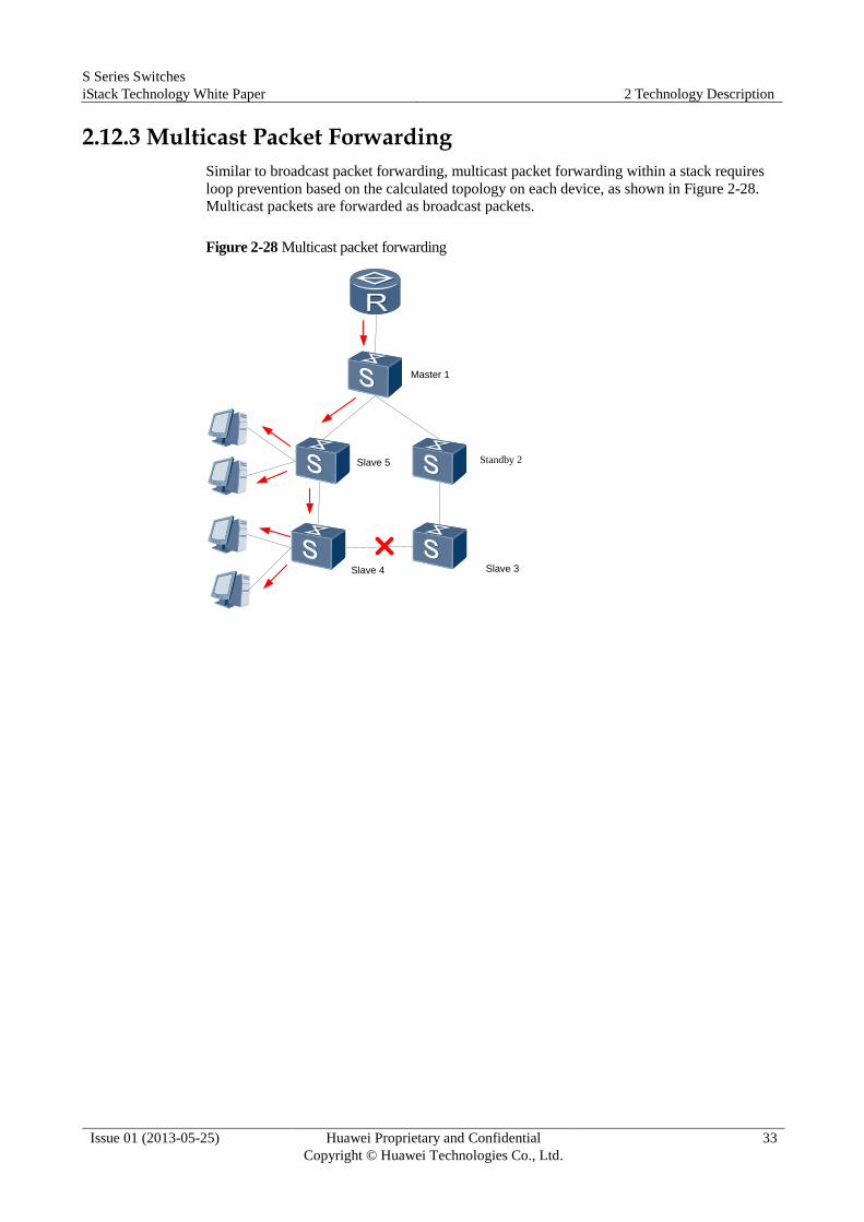
2.12.3 Multicast Packet Forwarding
Similar to broadcast packet forwarding, multicast packet forwarding within a stack requires
loop prevention based on the calculated topology on each device, as shown in Figure 2-28.
Multicast packets are forwarded as broadcast packets.
Figure 2-28 Multicast packet forwarding
Master 1
Slave 5 Standby 2
Slave 4 Slave 3
S Series Switches
iStack Technology White Paper 2 Technology Description
Issue 01 (2013-05-25) Huawei Proprietary and Confidential
Copyright © Huawei Technologies Co., Ltd.
34
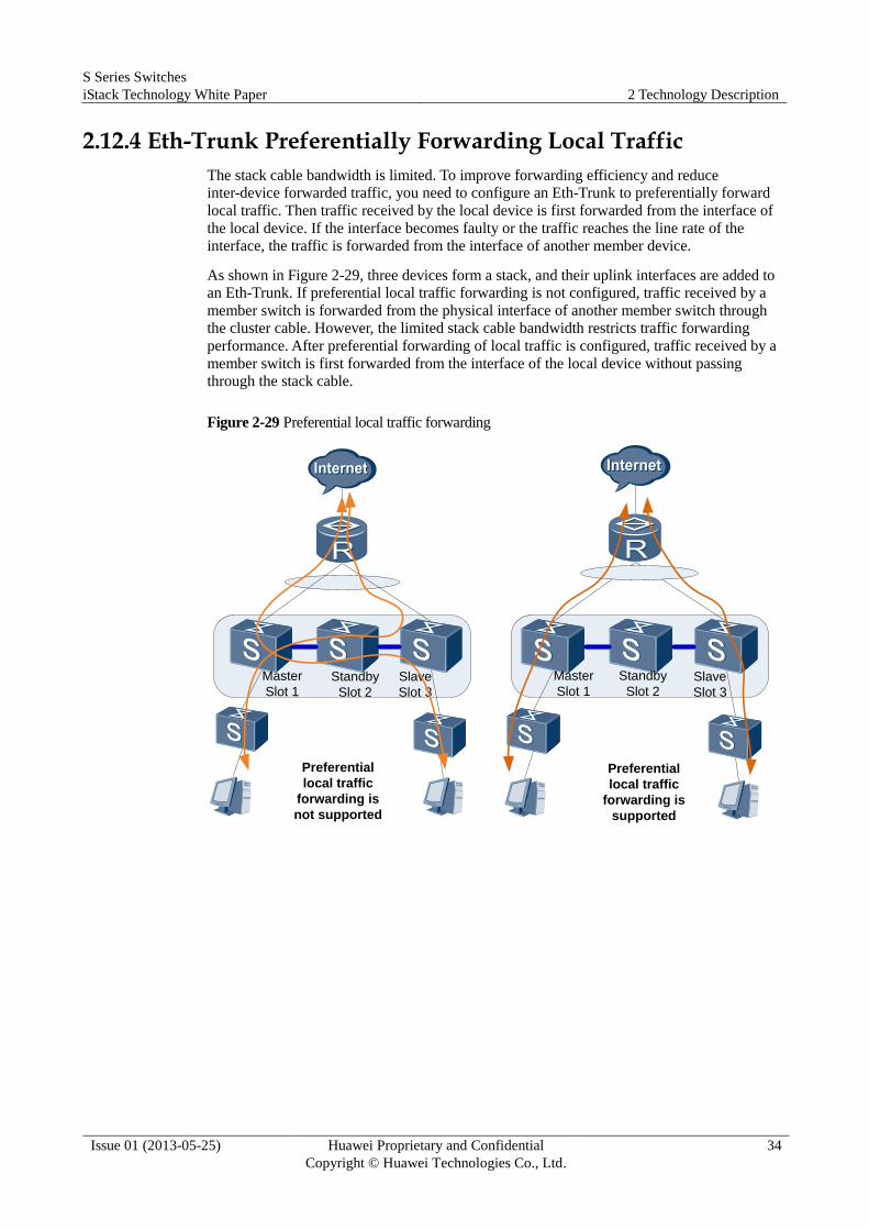
2.12.4 Eth-Trunk Preferentially Forwarding Local Traffic
The stack cable bandwidth is limited. To improve forwarding efficiency and reduce
inter-device forwarded traffic, you need to configure an Eth-Trunk to preferentially forward
local traffic. Then traffic received by the local device is first forwarded from the interface of
the local device. If the interface becomes faulty or the traffic reaches the line rate of the
interface, the traffic is forwarded from the interface of another member device.
As shown in Figure 2-29, three devices form a stack, and their uplink interfaces are added to
an Eth-Trunk. If preferential local traffic forwarding is not configured, traffic received by a
member switch is forwarded from the physical interface of another member switch through
the cluster cable. However, the limited stack cable bandwidth restricts traffic forwarding
performance. After preferential forwarding of local traffic is configured, traffic received by a
member switch is first forwarded from the interface of the local device without passing
through the stack cable.
Figure 2-29 Preferential local traffic forwarding
Master
Slot 1Standby
Slot 2
Slave
Slot 3
Master
Slot 1
Standby
Slot 2Slave
Slot 3
Preferential
local traffic
forwarding is
not supported
Preferential
local traffic
forwarding is
supported

S Series Switches
iStack Technology White Paper 3 Product Capability
Issue 01 (2013-05-25) Huawei Proprietary and Confidential
Copyright © Huawei Technologies Co., Ltd.
35
3 Product Capability
NOTE
The product capabilities in this section are subject to change without notice because of version upgrades.
For details about product capabilities, see the specifications lists of products.
3.1 Stack Cables
SFP Cable
Table 3-1 SFP cable
Attribute Description
Cable model SFP high-speed cable-indoor-(SFP 20M)-(SFP 20M)-SFP-(CC2P0.32
black)-1.5m
Connector X1/X2 SFP, 20-pin, male
Color Black
Length 1.5 m
Bend radius 40 mm
SFP+ Cable
Table 3-2 SFP+ 1 m passive cable
Attribute Description
Cable model SFP+ high-speed cable-1m-(SFP+20M)-(CC2P0.254
black)-(SFP+20M)-indoor low-fume, halogenless and flame-retardant
cable
Connector X1/X2 SFP, 20-pin, male
Color Black

S Series Switches
iStack Technology White Paper 3 Product Capability
Issue 01 (2013-05-25) Huawei Proprietary and Confidential
Copyright © Huawei Technologies Co., Ltd.
36
Attribute Description
Length 1 m
Bend radius 25 mm
Table 3-3 SFP+ 3 m passive cable
Attribute Description
Cable model Outsourcing cable-SFP+ high-speed cable-3m-SFP+20M-CC2P0.254
black-SFP+20M-indoor low-fume, halogenless and flame-retardant
cable
Connector X1/X2 SFP, 20-pin, male
Color Black
Length 3 m
Bend radius 25 mm
Table 3-4 SFP+ 10 m passive cable
Attribute Description
Cable model Outsourcing cable-SFP+ high-speed cable-10m-SFP+20M-CC2P0.5
black-SFP+20M-indoor low-fume, halogenless and flame-retardant
cable
Connector X1/X2 SFP, 20-pin, male
Color Black
Length 10 m
Bend radius 30 mm
Table 3-5 SFP+ 10 m active cable
Attribute Description
Cable model Outsourcing cable-SFP+ active high-speed
cable-10m-(SFP+20M)-(CC2P0.32 black)-(SFP+20M)-indoor
low-fume, halogenless and flame-retardant cable
Connector X1/X2 SFP, 20-pin, male
Color Black
Length 10 m
S Series Switches
iStack Technology White Paper 3 Product Capability
Issue 01 (2013-05-25) Huawei Proprietary and Confidential
Copyright © Huawei Technologies Co., Ltd.
37
Attribute Description
Bend radius 25 mm
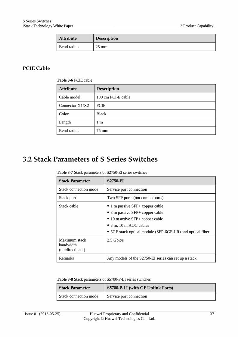
PCIE Cable
Table 3-6 PCIE cable
Attribute Description
Cable model 100 cm PCI-E cable
Connector X1/X2 PCIE
Color Black
Length 1 m
Bend radius 75 mm
3.2 Stack Parameters of S Series Switches
Table 3-7 Stack parameters of S2750-EI series switches
Stack Parameter S2750-EI
Stack connection mode Service port connection
Stack port Two SFP ports (not combo ports)
Stack cable 1 m passive SFP+ copper cable
3 m passive SFP+ copper cable
10 m active SFP+ copper cable
3 m, 10 m AOC cables
6GE stack optical module (SFP-6GE-LR) and optical fiber
Maximum stack
bandwidth
(unidirectional)
2.5 Gbit/s
Remarks Any models of the S2750-EI series can set up a stack.
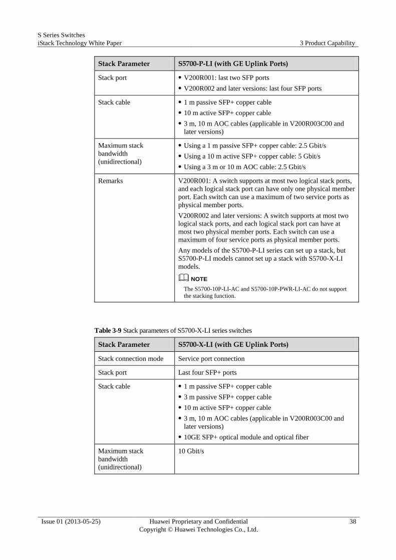
Table 3-8 Stack parameters of S5700-P-LI series switches
Stack Parameter S5700-P-LI (with GE Uplink Ports)
Stack connection mode Service port connection
S Series Switches
iStack Technology White Paper 3 Product Capability
Issue 01 (2013-05-25) Huawei Proprietary and Confidential
Copyright © Huawei Technologies Co., Ltd.
38
Stack Parameter S5700-P-LI (with GE Uplink Ports)
Stack port V200R001: last two SFP ports
V200R002 and later versions: last four SFP ports
Stack cable 1 m passive SFP+ copper cable
10 m active SFP+ copper cable
3 m, 10 m AOC cables (applicable in V200R003C00 and
later versions)
Maximum stack
bandwidth
(unidirectional)
Using a 1 m passive SFP+ copper cable: 2.5 Gbit/s
Using a 10 m active SFP+ copper cable: 5 Gbit/s
Using a 3 m or 10 m AOC cable: 2.5 Gbit/s
Remarks V200R001: A switch supports at most two logical stack ports,
and each logical stack port can have only one physical member
port. Each switch can use a maximum of two service ports as
physical member ports.
V200R002 and later versions: A switch supports at most two
logical stack ports, and each logical stack port can have at
most two physical member ports. Each switch can use a
maximum of four service ports as physical member ports.
Any models of the S5700-P-LI series can set up a stack, but
S5700-P-LI models cannot set up a stack with S5700-X-LI
models.
NOTE
The S5700-10P-LI-AC and S5700-10P-PWR-LI-AC do not support
the stacking function.
Table 3-9 Stack parameters of S5700-X-LI series switches
Stack Parameter S5700-X-LI (with GE Uplink Ports)
Stack connection mode Service port connection
Stack port Last four SFP+ ports
Stack cable 1 m passive SFP+ copper cable
3 m passive SFP+ copper cable
10 m active SFP+ copper cable
3 m, 10 m AOC cables (applicable in V200R003C00 and
later versions)
10GE SFP+ optical module and optical fiber
Maximum stack
bandwidth
(unidirectional)
10 Gbit/s
S Series Switches
iStack Technology White Paper 3 Product Capability
Issue 01 (2013-05-25) Huawei Proprietary and Confidential
Copyright © Huawei Technologies Co., Ltd.
39
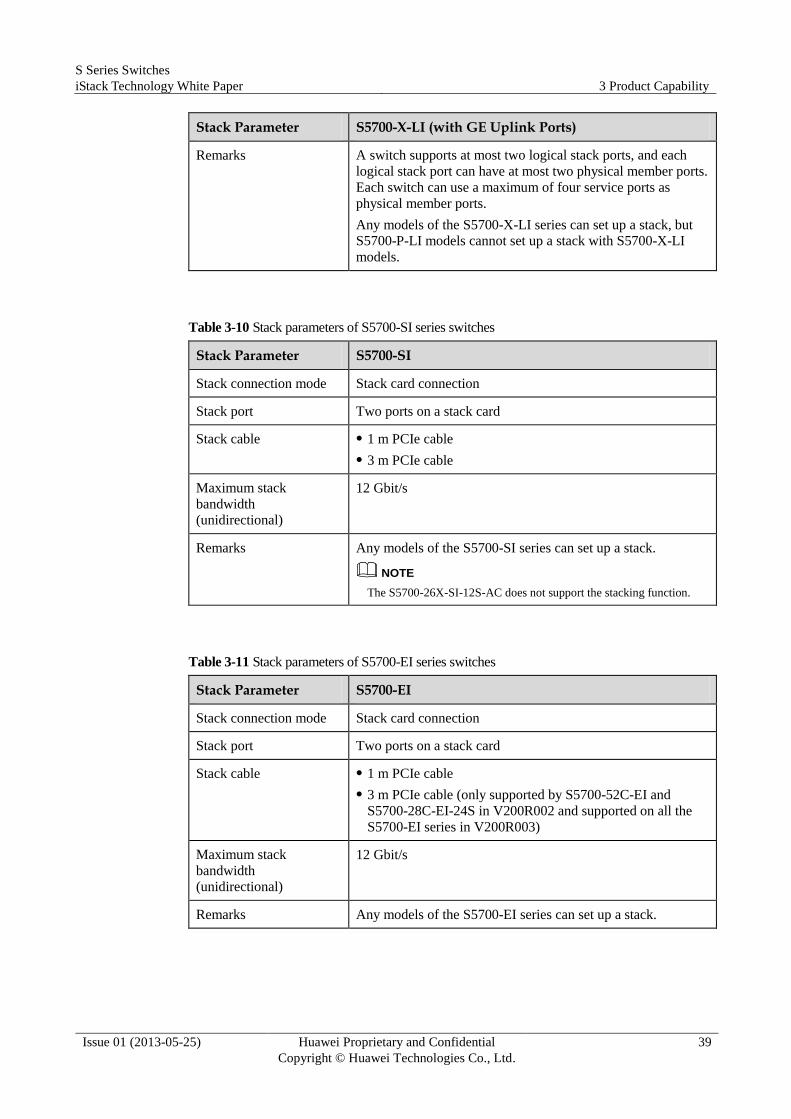
Stack Parameter S5700-X-LI (with GE Uplink Ports)
Remarks A switch supports at most two logical stack ports, and each
logical stack port can have at most two physical member ports.
Each switch can use a maximum of four service ports as
physical member ports.
Any models of the S5700-X-LI series can set up a stack, but
S5700-P-LI models cannot set up a stack with S5700-X-LI
models.
Table 3-10 Stack parameters of S5700-SI series switches
Stack Parameter S5700-SI
Stack connection mode Stack card connection
Stack port Two ports on a stack card
Stack cable 1 m PCIe cable
3 m PCIe cable
Maximum stack
bandwidth
(unidirectional)
12 Gbit/s
Remarks Any models of the S5700-SI series can set up a stack.
NOTE
The S5700-26X-SI-12S-AC does not support the stacking function.
Table 3-11 Stack parameters of S5700-EI series switches
Stack Parameter S5700-EI
Stack connection mode Stack card connection
Stack port Two ports on a stack card
Stack cable 1 m PCIe cable
3 m PCIe cable (only supported by S5700-52C-EI and
S5700-28C-EI-24S in V200R002 and supported on all the
S5700-EI series in V200R003)
Maximum stack
bandwidth
(unidirectional)
12 Gbit/s
Remarks Any models of the S5700-EI series can set up a stack.

S Series Switches
iStack Technology White Paper 3 Product Capability
Issue 01 (2013-05-25) Huawei Proprietary and Confidential
Copyright © Huawei Technologies Co., Ltd.
40
Table 3-12 Stack parameters of S5710-EI series switches
Stack Parameter S5710-EI
Stack connection mode Service port connection
Stack port Any 10GE ports, including the four fixed 10GE SFP+ optical
ports on the front panel and ports on the ES5D21X02S00 rear
card (A switch supports a maximum of two rear cards, and
each card provides two 10GE SFP+ optical ports.)
NOTE
Each logical stack port can have a maximum of four physical member
ports. Ports on different rear cards can be added to the same logical
stack port, but ports on a rear card and fixed ports on the front panel
cannot be added to the same logical stack port.
Stack cable 1 m passive SFP+ copper cable
3 m passive SFP+ copper cable
10 m active SFP+ copper cable
3 m, 10 m AOC cables (applicable in V200R003C00 and
later versions)
10GE SFP+ optical module and optical fiber
Maximum stack
bandwidth
(unidirectional)
10 Gbit/s
Remarks V200R001: A switch supports at most two logical stack ports,
and each logical stack port can have at most three physical
member ports. Each switch can use a maximum of four service
ports as physical member ports. All physical member ports
must be located on the front panel or rear subcards.
V200R002 and later versions: A switch supports at most two
logical stack ports, and each logical stack port can have at
most four physical member ports. Each switch can use a
maximum of eight service ports as physical member ports.
Any models of the S5710-EI series can set up a stack.
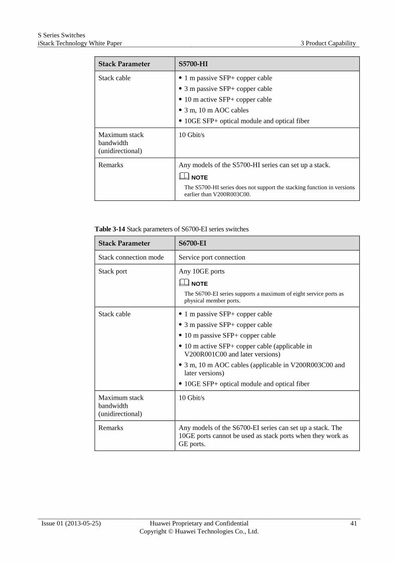
Table 3-13 Stack parameters of S5700-HI series switches
Stack Parameter S5700-HI
Stack connection mode Service port connection
Stack port 10GE ports on front cards: The S5700-HI supports
ES5D00X2SA00 and ES5D00X4SA00 front cards, which
support two and four 10GE SFP+ optical ports respectively.
NOTE
After a front card is replaced, the stack configurations become invalid
and need to be reconfigured.
S Series Switches
iStack Technology White Paper 3 Product Capability
Issue 01 (2013-05-25) Huawei Proprietary and Confidential
Copyright © Huawei Technologies Co., Ltd.
41
Stack Parameter S5700-HI
Stack cable 1 m passive SFP+ copper cable
3 m passive SFP+ copper cable
10 m active SFP+ copper cable
3 m, 10 m AOC cables
10GE SFP+ optical module and optical fiber
Maximum stack
bandwidth
(unidirectional)
10 Gbit/s
Remarks Any models of the S5700-HI series can set up a stack.
NOTE
The S5700-HI series does not support the stacking function in versions
earlier than V200R003C00.
Table 3-14 Stack parameters of S6700-EI series switches
Stack Parameter S6700-EI
Stack connection mode Service port connection
Stack port Any 10GE ports
NOTE
The S6700-EI series supports a maximum of eight service ports as
physical member ports.
Stack cable 1 m passive SFP+ copper cable
3 m passive SFP+ copper cable
10 m passive SFP+ copper cable
10 m active SFP+ copper cable (applicable in
V200R001C00 and later versions)
3 m, 10 m AOC cables (applicable in V200R003C00 and
later versions)
10GE SFP+ optical module and optical fiber
Maximum stack
bandwidth
(unidirectional)
10 Gbit/s
Remarks Any models of the S6700-EI series can set up a stack. The
10GE ports cannot be used as stack ports when they work as
GE ports.
S Series Switches
iStack Technology White Paper 3 Product Capability
Issue 01 (2013-05-25) Huawei Proprietary and Confidential
Copyright © Huawei Technologies Co., Ltd.
42
3.3 Switches That Do Not Support Stacking
S5706, S5700S-LI, and S5710-HI do not support the stacking function.

S Series Switches
iStack Technology White Paper 4 Application Scenarios
Issue 01 (2013-05-25) Huawei Proprietary and Confidential
Copyright © Huawei Technologies Co., Ltd.
43
4 Application Scenarios
4.1 Configuring a Stack with a Ring Topology
Networking Requirements
As shown in Figure 4-1, SwitchA, SwitchB, SwitchC, and SwitchD need to set up a stack
with a ring topology.
As the network scale rapidly increases, the number of interfaces provided by an access switch
cannot meet server access requirements. To meet these requirements, the number of access
interfaces needs to be increased without increasing the existing investment, and the network
must be easy to manage and maintain.
The following uses the S5700-LI as an example to describe how to configure a stack in
service port connection mode with a ring topology.
Figure 4-1 Diagram of configuring a stack with a ring topology
SwitchA
SwitchC SwitchD
SwitchB
Stack link
Common link
GE0/0/27
GE0/0/28GE0/0/27
GE0/0/28
GE0/0/27
GE0/0/28
GE0/0/27
GE0/0/28

S Series Switches
iStack Technology White Paper 4 Application Scenarios
Issue 01 (2013-05-25) Huawei Proprietary and Confidential
Copyright © Huawei Technologies Co., Ltd.
44
Configuration Roadmap
1. Configure physical member interfaces and add them to stack interfaces to ensure that
member switches can forward data packets. Physical member interfaces on both ends of
a stack link must be added to different stack interfaces.
2. Connect interfaces using SFP+ cables as shown in Figure 4-1.
Configuration Procedure
Step 1 Configure stack interfaces.
# On SwitchA, configure GigabitEthernet0/0/27 and GigabitEthernet0/0/28 as physical
member interfaces and add them to stack port 0/1 and stack port 0/2 respectively.
<HUAWEI> system-view
[HUAWEI] sysname SwitchA
[SwitchA] interface stack-port 0/1
[SwitchA-stack-port0/1] port interface gigabitethernet 0/0/27 enable
Warning: Enabling stack port cause configuration loss on the interface, continue?[Y/N]:y
Info: This operation may take a few seconds. Please wait for a moment.......
[SwitchA-stack-port0/1] quit
[SwitchA] interface stack-port 0/2
[SwitchA-stack-port0/2] port interface gigabitethernet 0/0/28 enable
Warning: Enabling stack port cause configuration loss on the interface, continue?[Y/N]:y
Info: This operation may take a few seconds. Please wait for a moment.......
[SwitchA-stack-port0/2] quit
# On SwitchB, configure GigabitEthernet0/0/27 and GigabitEthernet0/0/28 as physical
member interfaces and add them to stack port 0/1 and stack port 0/2 respectively.
<HUAWEI> system-view
[HUAWEI] sysname SwitchB
[SwitchB] interface stack-port 0/1
[SwitchB-stack-port0/1] port interface gigabitethernet 0/0/27 enable
Warning: Enabling stack port cause configuration loss on the interface, continue?[Y/N]:y
Info: This operation may take a few seconds. Please wait for a moment.......
[SwitchB-stack-port0/1] quit
[SwitchB] interface stack-port 0/2
[SwitchB-stack-port0/2] port interface gigabitethernet 0/0/28 enable
Warning: Enabling stack port cause configuration loss on the interface, continue?[Y/N]:y
Info: This operation may take a few seconds. Please wait for a moment.......
[SwitchB-stack-port0/2] quit
# On SwitchC, configure GigabitEthernet0/0/27 and GigabitEthernet0/0/28 as physical
member interfaces and add them to stack port 0/1 and stack port 0/2 respectively.
<HUAWEI> system-view
[HUAWEI] sysname SwitchC
[SwitchC] interface stack-port 0/1
[SwitchC-stack-port0/1] port interface gigabitethernet 0/0/27 enable
Warning: Enabling stack port cause configuration loss on the interface, continue?[Y/N]:y
Info: This operation may take a few seconds. Please wait for a moment.......
[SwitchC-stack-port0/1] quit
[SwitchC] interface stack-port 0/2
[SwitchC-stack-port0/2] port interface gigabitethernet 0/0/28 enable
Warning: Enabling stack port cause configuration loss on the interface, continue?[Y/N]:y
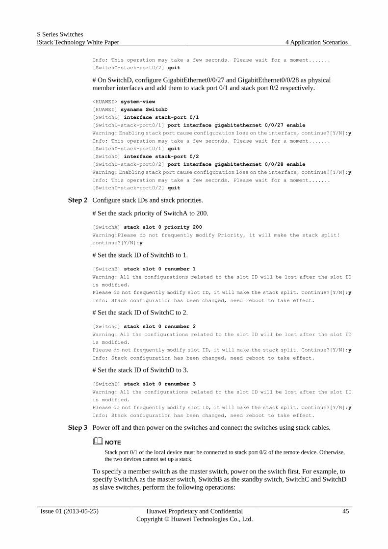
S Series Switches
iStack Technology White Paper 4 Application Scenarios
Issue 01 (2013-05-25) Huawei Proprietary and Confidential
Copyright © Huawei Technologies Co., Ltd.
45
Info: This operation may take a few seconds. Please wait for a moment.......
[SwitchC-stack-port0/2] quit
# On SwitchD, configure GigabitEthernet0/0/27 and GigabitEthernet0/0/28 as physical
member interfaces and add them to stack port 0/1 and stack port 0/2 respectively.
<HUAWEI> system-view
[HUAWEI] sysname SwitchD
[SwitchD] interface stack-port 0/1
[SwitchD-stack-port0/1] port interface gigabitethernet 0/0/27 enable
Warning: Enabling stack port cause configuration loss on the interface, continue?[Y/N]:y
Info: This operation may take a few seconds. Please wait for a moment.......
[SwitchD-stack-port0/1] quit
[SwitchD] interface stack-port 0/2
[SwitchD-stack-port0/2] port interface gigabitethernet 0/0/28 enable
Warning: Enabling stack port cause configuration loss on the interface, continue?[Y/N]:y
Info: This operation may take a few seconds. Please wait for a moment.......
[SwitchD-stack-port0/2] quit
Step 2 Configure stack IDs and stack priorities.
# Set the stack priority of SwitchA to 200.
[SwitchA] stack slot 0 priority 200
Warning:Please do not frequently modify Priority, it will make the stack split!
continue?[Y/N]:y
# Set the stack ID of SwitchB to 1.
[SwitchB] stack slot 0 renumber 1
Warning: All the configurations related to the slot ID will be lost after the slot ID
is modified.
Please do not frequently modify slot ID, it will make the stack split. Continue?[Y/N]:y
Info: Stack configuration has been changed, need reboot to take effect.
# Set the stack ID of SwitchC to 2.
[SwitchC] stack slot 0 renumber 2
Warning: All the configurations related to the slot ID will be lost after the slot ID
is modified.
Please do not frequently modify slot ID, it will make the stack split. Continue?[Y/N]:y
Info: Stack configuration has been changed, need reboot to take effect.
# Set the stack ID of SwitchD to 3.
[SwitchD] stack slot 0 renumber 3
Warning: All the configurations related to the slot ID will be lost after the slot ID
is modified.
Please do not frequently modify slot ID, it will make the stack split. Continue?[Y/N]:y
Info: Stack configuration has been changed, need reboot to take effect.
Step 3 Power off and then power on the switches and connect the switches using stack cables.
NOTE
Stack port 0/1 of the local device must be connected to stack port 0/2 of the remote device. Otherwise,
the two devices cannot set up a stack.
To specify a member switch as the master switch, power on the switch first. For example, to
specify SwitchA as the master switch, SwitchB as the standby switch, SwitchC and SwitchD
as slave switches, perform the following operations:
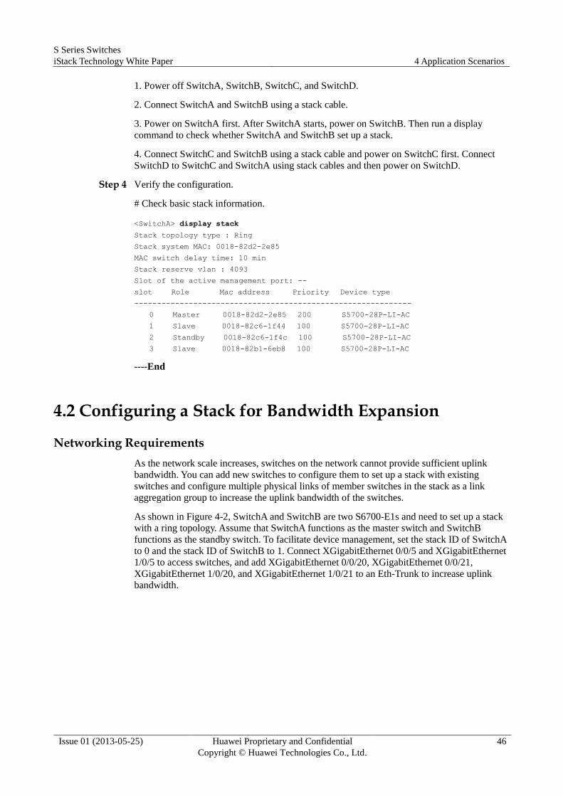
S Series Switches
iStack Technology White Paper 4 Application Scenarios
Issue 01 (2013-05-25) Huawei Proprietary and Confidential
Copyright © Huawei Technologies Co., Ltd.
46
1. Power off SwitchA, SwitchB, SwitchC, and SwitchD.
2. Connect SwitchA and SwitchB using a stack cable.
3. Power on SwitchA first. After SwitchA starts, power on SwitchB. Then run a display
command to check whether SwitchA and SwitchB set up a stack.
4. Connect SwitchC and SwitchB using a stack cable and power on SwitchC first. Connect
SwitchD to SwitchC and SwitchA using stack cables and then power on SwitchD.
Step 4 Verify the configuration.
# Check basic stack information.
<SwitchA> display stack
Stack topology type : Ring
Stack system MAC: 0018-82d2-2e85
MAC switch delay time: 10 min
Stack reserve vlan : 4093
Slot of the active management port: --
slot Role Mac address Priority Device type
-------------------------------------------------------------
0 Master 0018-82d2-2e85 200 S5700-28P-LI-AC
1 Slave 0018-82c6-1f44 100 S5700-28P-LI-AC
2 Standby 0018-82c6-1f4c 100 S5700-28P-LI-AC
3 Slave 0018-82b1-6eb8 100 S5700-28P-LI-AC
----End
4.2 Configuring a Stack for Bandwidth Expansion
Networking Requirements
As the network scale increases, switches on the network cannot provide sufficient uplink
bandwidth. You can add new switches to configure them to set up a stack with existing
switches and configure multiple physical links of member switches in the stack as a link
aggregation group to increase the uplink bandwidth of the switches.
As shown in Figure 4-2, SwitchA and SwitchB are two S6700-E1s and need to set up a stack
with a ring topology. Assume that SwitchA functions as the master switch and SwitchB
functions as the standby switch. To facilitate device management, set the stack ID of SwitchA
to 0 and the stack ID of SwitchB to 1. Connect XGigabitEthernet 0/0/5 and XGigabitEthernet
1/0/5 to access switches, and add XGigabitEthernet 0/0/20, XGigabitEthernet 0/0/21,
XGigabitEthernet 1/0/20, and XGigabitEthernet 1/0/21 to an Eth-Trunk to increase uplink
bandwidth.
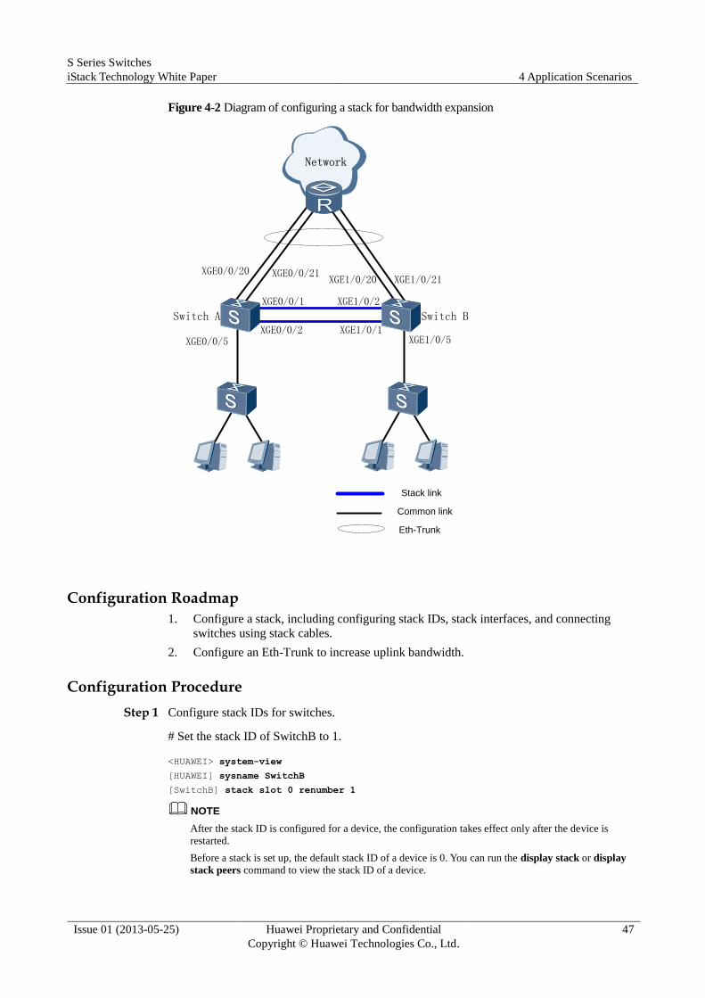
S Series Switches
iStack Technology White Paper 4 Application Scenarios
Issue 01 (2013-05-25) Huawei Proprietary and Confidential
Copyright © Huawei Technologies Co., Ltd.
47
Figure 4-2 Diagram of configuring a stack for bandwidth expansion
Switch A Switch B
XGE0/0/1
XGE0/0/20 XGE0/0/21XGE1/0/20 XGE1/0/21
XGE0/0/5 XGE1/0/5
Network
Eth-Trunk
Stack link
Common link
XGE1/0/1
XGE1/0/2
XGE0/0/2
Configuration Roadmap
1. Configure a stack, including configuring stack IDs, stack interfaces, and connecting
switches using stack cables.
2. Configure an Eth-Trunk to increase uplink bandwidth.
Configuration Procedure
Step 1 Configure stack IDs for switches.
# Set the stack ID of SwitchB to 1.
<HUAWEI> system-view
[HUAWEI] sysname SwitchB
[SwitchB] stack slot 0 renumber 1
NOTE
After the stack ID is configured for a device, the configuration takes effect only after the device is
restarted.
Before a stack is set up, the default stack ID of a device is 0. You can run the display stack or display
stack peers command to view the stack ID of a device.

S Series Switches
iStack Technology White Paper 4 Application Scenarios
Issue 01 (2013-05-25) Huawei Proprietary and Confidential
Copyright © Huawei Technologies Co., Ltd.
48
Step 2 Configure stack interfaces.
# On SwitchA, configure XGigabitEthernet0/0/1 and GigabitEthernet0/0/2 as physical
member interfaces and add them to stack port 0/1 and stack port 0/2 respectively.
<HUAWEI> system-view
[HUAWEI] sysname SwitchA
[SwitchA] interface stack-port 0/1
[SwitchA-stack-port0/1] port interface XGigabitEthernet 0/0/1 enable
Warning: Enabling stack port cause configuration loss on the interface, continue?[Y/N]:y
Info: This operation may take a few seconds. Please wait for a moment.......
Info: Ports XGigabitEthernet0/0/1 to XGigabitEthernet0/0/4 have been configured as
physical stack-port.
[SwitchA-stack-port0/1] quit
[SwitchA] interface stack-port 0/2
[SwitchA-stack-port0/2] port interface XGigabitEthernet 0/0/2 enable
Warning: Enabling stack port cause configuration loss on the interface, continue?[Y/N]:y
Info: This operation may take a few seconds. Please wait for a moment.......
Info: Ports XGigabitEthernet0/0/1 to XGigabitEthernet0/0/4 have been configured as
physical stack-port.
[SwitchA-stack-port0/2] quit
# On SwitchB, configure XGigabitEthernet0/0/1 and GigabitEthernet0/0/2 as physical
member interfaces and add them to stack port 0/1 and stack port 0/2 respectively.
<SwitchB> system-view
[SwitchB] interface stack-port 0/1
[SwitchB-stack-port0/1] port interface XGigabitEthernet 0/0/1 enable
Warning: Enabling stack port cause configuration loss on the interface, continue?[Y/N]:y
Info: This operation may take a few seconds. Please wait for a moment.......
Info: Ports XGigabitEthernet0/0/1 to XGigabitEthernet0/0/4 have been configured as
physical stack-port.
[SwitchB-stack-port0/1] quit
[SwitchB] interface stack-port 0/2
[SwitchB-stack-port0/2] port interface XGigabitEthernet 0/0/2 enable
Warning: Enabling stack port cause configuration loss on the interface, continue?[Y/N]:y
Info: This operation may take a few seconds. Please wait for a moment.......
Info: Ports XGigabitEthernet0/0/1 to XGigabitEthernet0/0/4 have been configured as
physical stack-port.
[SwitchB-stack-port0/2] quit
Step 3 Power cycle the switches and connect the switches through stack cables.
NOTE
Power off SwitchA and SwitchB, connect the two switches through stack cables, and then power on
SwitchA and SwitchB in sequence.
Stack port 0/1 of the local device must be connected to stack port 0/2 of the remote device. Otherwise,
the two devices cannot set up a stack.
Step 4 View the stack configuration.
<SwitchA> display stack
Stack topology type: Ring
Stack system MAC: 80fb-06af-7570
MAC switch delay time: 10 min
Stack reserve vlan : 4093
Slot of the active management port: --
slot Role Mac address Priority Device type

S Series Switches
iStack Technology White Paper 4 Application Scenarios
Issue 01 (2013-05-25) Huawei Proprietary and Confidential
Copyright © Huawei Technologies Co., Ltd.
49
-------------------------------------------------------------
0 Master 80fb-06af-7570 100 S6700-48-EI
1 Standby 80fb-06af-7ed0 100 S6700-48-EI
Step 5 Configure a user VLAN and add the interfaces that connect access switches to the VLAN.
<SwitchA> system-view
[SwitchA] vlan 100
[SwitchA] vlan 100
[SwitchA-vlan100] quit
[SwitchA] interface XGigabitEthernet 0/0/5
[SwitchA-XGigabitEthernet 0/0/5] port link-type trunk
[SwitchA-XGigabitEthernet 0/0/5] port trunk allow-pass vlan 100
[SwitchA-XGigabitEthernet 0/0/5] quit
[SwitchA] interface XGigabitEthernet 1/0/5
[SwitchA-XGigabitEthernet 1/0/5] port link-type trunk
[SwitchA-XGigabitEthernet 1/0/5] port trunk allow-pass vlan 100
[SwitchA-XGigabitEthernet 1/0/5] quit
Step 6 Configure an Eth-Trunk and add uplink interfaces to the Eth-Trunk.
<SwitchA> system-view
[SwitchA] interface Eth-Trunk 10
[SwitchA-Eth-Trunk10] port link-type trunk
[SwitchA-Eth-Trunk10] port trunk allow-pass vlan 100
[SwitchA-Eth-Trunk10] trunkport XGigabitEthernet 0/0/20 to 0/0/21
[SwitchA-Eth-Trunk10] trunkport XGigabitEthernet 1/0/20 to 1/0/21
[SwitchA-Eth-Trunk10] quit
----End
4.3 Example for Configuring MAD in Direct Mode
Networking Requirements
As shown in Figure 4-3, SwitchA and SwitchB form a stack. The stack IDs of SwitchA and
SwitchB are 0 and 1 respectively.
To ensure stack reliability, MAD in direct mode needs to be configured on
GigabitEthernet0/0/5 and GigabitEthernet1/0/5. When the stack splits because of a stack link
fault and there are two devices with the same configuration on the network, you can use MAD
to reduce the impact of a stack split on the network.
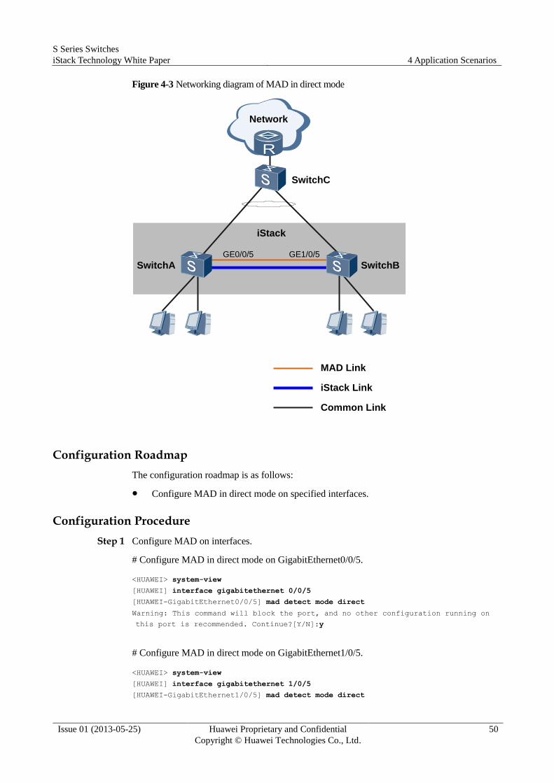
S Series Switches
iStack Technology White Paper 4 Application Scenarios
Issue 01 (2013-05-25) Huawei Proprietary and Confidential
Copyright © Huawei Technologies Co., Ltd.
50
Figure 4-3 Networking diagram of MAD in direct mode
Network
iStack
SwitchA SwitchBGE0/0/5 GE1/0/5
SwitchC
MAD Link
iStack Link
Common Link
Configuration Roadmap
The configuration roadmap is as follows:
Configure MAD in direct mode on specified interfaces.
Configuration Procedure
Step 1 Configure MAD on interfaces.
# Configure MAD in direct mode on GigabitEthernet0/0/5.
<HUAWEI> system-view
[HUAWEI] interface gigabitethernet 0/0/5
[HUAWEI-GigabitEthernet0/0/5] mad detect mode direct
Warning: This command will block the port, and no other configuration running on
this port is recommended. Continue?[Y/N]:y
# Configure MAD in direct mode on GigabitEthernet1/0/5.
<HUAWEI> system-view
[HUAWEI] interface gigabitethernet 1/0/5
[HUAWEI-GigabitEthernet1/0/5] mad detect mode direct
S Series Switches
iStack Technology White Paper 4 Application Scenarios
Issue 01 (2013-05-25) Huawei Proprietary and Confidential
Copyright © Huawei Technologies Co., Ltd.
51
Warning: This command will block the port, and no other configuration running on
this port is recommended. Continue?[Y/N]:y
Step 2 Verify the configuration.
# Check detailed MAD configuration of the stack.
<HUAWEI> display mad verbose
Current MAD domain: 0
Current MAD status: Detect
Mad direct detect interfaces configured:
GigabitEthernet0/0/5
GigabitEthernet1/0/5
Mad relay detect interfaces configured:
Excluded ports(configurable):
Excluded ports(cannot be configured):
GigabitEthernet0/0/27
GigabitEthernet1/0/27
----End
Configuration File Configuration file of the stack
#
interface GigabitEthernet0/0/5
mad detect mode direct
#
interface GigabitEthernet1/0/5
mad detect mode direct
#
return
4.4 Example for Configuring MAD in Relay Mode
Network Requirements
As shown in Figure 4-4, SwitchA, SwitchB and SwitchC form a stack. SwitchA, SwitchB and
SwitchC connect to SwitchD using Eth-Trunk1.
When the stack splits because of a stack link fault and there are two devices with the same
configuration on the network, you can use MAD to reduce the impact of a stack split on the
network.
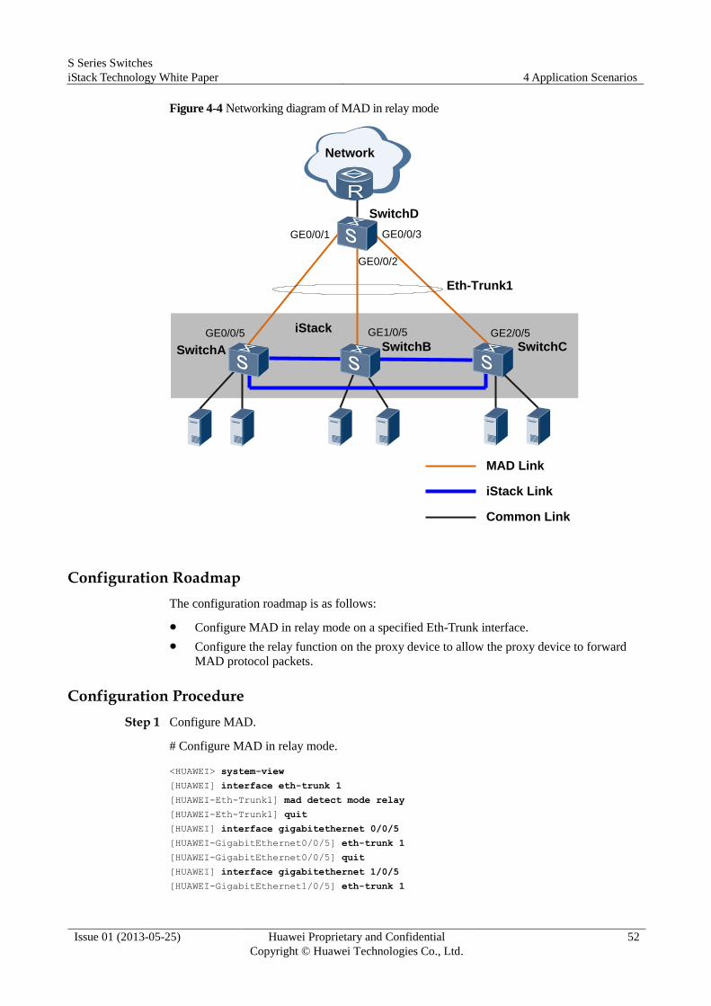
S Series Switches
iStack Technology White Paper 4 Application Scenarios
Issue 01 (2013-05-25) Huawei Proprietary and Confidential
Copyright © Huawei Technologies Co., Ltd.
52
Figure 4-4 Networking diagram of MAD in relay mode
Network
SwitchA SwitchC
SwitchD
Eth-Trunk1
MAD Link
iStack Link
Common Link
iStack GE2/0/5GE0/0/5
GE0/0/3GE0/0/1
SwitchB
GE1/0/5
GE0/0/2
Configuration Roadmap
The configuration roadmap is as follows:
Configure MAD in relay mode on a specified Eth-Trunk interface.
Configure the relay function on the proxy device to allow the proxy device to forward
MAD protocol packets.
Configuration Procedure
Step 1 Configure MAD.
# Configure MAD in relay mode.
<HUAWEI> system-view
[HUAWEI] interface eth-trunk 1
[HUAWEI-Eth-Trunk1] mad detect mode relay
[HUAWEI-Eth-Trunk1] quit
[HUAWEI] interface gigabitethernet 0/0/5
[HUAWEI-GigabitEthernet0/0/5] eth-trunk 1
[HUAWEI-GigabitEthernet0/0/5] quit
[HUAWEI] interface gigabitethernet 1/0/5
[HUAWEI-GigabitEthernet1/0/5] eth-trunk 1
S Series Switches
iStack Technology White Paper 4 Application Scenarios
Issue 01 (2013-05-25) Huawei Proprietary and Confidential
Copyright © Huawei Technologies Co., Ltd.
53
[HUAWEI-GigabitEthernet1/0/5] quit
[HUAWEI] interface gigabitethernet 2/0/5
[HUAWEI-GigabitEthernet2/0/5] eth-trunk 1
[HUAWEI-GigabitEthernet2/0/5] quit
Step 2 Configure the relay function.
# Configure the relay function on proxy device SwitchD.
<HUAWEI> system-view
[HUAWEI] sysname SwitchD
[SwitchD] interface eth-trunk 1
[SwitchD-Eth-Trunk1] mad relay
[SwitchD-Eth-Trunk1] quit
[SwitchD] interface gigabitethernet 0/0/1
[SwitchD-GigabitEthernet0/0/1] eth-trunk 1
[SwitchD-GigabitEthernet0/0/1] quit
[SwitchD] interface gigabitethernet 0/0/2
[SwitchD-GigabitEthernet0/0/2] eth-trunk 1
[SwitchD-GigabitEthernet0/0/2] quit
[SwitchD] interface gigabitethernet 0/0/3
[SwitchD-GigabitEthernet0/0/3] eth-trunk 1
[SwitchC-GigabitEthernet0/0/3] quit
Step 3 Verify the configuration.
# Check detailed MAD configuration of the stack.
<HUAWEI> display mad verbose
Current MAD domain: 0
Current MAD status: Detect
Mad direct detect interfaces configured:
Mad relay detect interfaces configured:
Eth-Trunk1
Excluded ports(configurable):
Excluded ports(cannot be configured):
GigabitEthernet0/0/26
GigabitEthernet0/0/27
GigabitEthernet1/0/26
GigabitEthernet1/0/27
GigabitEthernet2/0/26
GigabitEthernet2/0/27
# Check information about the proxy device SwitchD.
<SwitchD> display mad proxy
Mad relay interfaces configured:
Eth-Trunk1
----End
Configuration File Configuration file of the stack
S Series Switches
iStack Technology White Paper 4 Application Scenarios
Issue 01 (2013-05-25) Huawei Proprietary and Confidential
Copyright © Huawei Technologies Co., Ltd.
54
#
interface Eth-Trunk1
mad detect mode relay
#
interface GigabitEthernet0/0/5
eth-trunk 1
#
interface GigabitEthernet1/0/5
eth-trunk 1
#
interface GigabitEthernet2/0/5
eth-trunk 1
#
return
Configuration file of SwitchD
#
sysname SwitchD
#
interface Eth-Trunk1
mad relay
#
interface GigabitEthernet0/0/1
eth-trunk 1
#
interface GigabitEthernet0/0/2
eth-trunk 1
#
interface GigabitEthernet0/0/3
eth-trunk 1
#
return
4.5 Adding a Member Switch to a Stack
In some scenarios, one or multiple new switches need to be added to a running stack to work
with existing member switches. This process involves the following steps:
Step 1 Collect the stack topology and prevent loops of stack links.
Before adding a new switch to a stack, analyze the physical connections of the stack.
If the stack has a chain topology, add the new switch to either end of the chain topology to
minimize the impact on existing services. Adding the new switch to the middle of the chain
topology will cause the split of the stack. Therefore, analyze the impact of adding a new
switch to a stack on existing services.
If the stack has a ring topology, change the ring topology into a chain topology and then add
the new switch on either end of the chain topology. In versions earlier than V200R001, you
need to select where to break the ring. It is not recommended to break the ring on the link
between the master and standby switches. Breaking the ring on the link between the master
and standby switches will cause the reelection of the standby switch and result in the role
changes of member switches.

S Series Switches
iStack Technology White Paper 4 Application Scenarios
Issue 01 (2013-05-25) Huawei Proprietary and Confidential
Copyright © Huawei Technologies Co., Ltd.
55
Step 2 Perform the stack configuration.
Configure stack interfaces on the existing edge switches of the stack. This configuration is
required only for a stack with a chain topology but not for a stack with a ring topology. For
details, see section 4.1 "Configuring a Stack with a Ring Topology."
Configure stack interfaces on the new switch.
To facilitate device management, configure a stack ID for the new switch. If no stack ID is
configured for the new switch, the stack assigns a stack ID to the new switch. For details, see
section 4.1 "Configuring a Stack with a Ring Topology."
Step 3 Connect the new switch using stack cables to add it to the stack.
Connect the new switch using stack cables. The switch joins the stack after being powered on.
CAUTION
Stack port n/1 of a device must be connected to stack port n/2 of the neighboring device.
Otherwise, the two devices cannot set up a stack. n indicates the stack ID of a member switch.
Step 4 Configure services on the new switch.
After the new switch joins the stack, you can configure services on the new switch.
Step 5 Repeat steps 1 to 4 to add multiple new switches to the stack.
----End
4.6 Removing a Member Switch from a Stack
In some scenarios, one or multiple member switches need to be removed from a running stack.
This process involves the following steps:
Step 1 Determine which member switches need to be removed.
The impact of removing member switches from a stack on existing services varies according
to the roles of the switches:
Removing the standby or slave switch from a stack results in short-term packet loss on
the switch but does not affect other devices.
You can remove the master switch from a stack in either of the following ways:
− Perform an active/standby switchover manually to change the master switch as a
slave switch and then remove it from the stack.
− Remove the master switch from the stack directly.
To minimize the impact of removing the master switch on existing services, perform an
active/standby switchover manually to change the master switch as a slave switch before
removing the master switch. Additionally, to ensure service reliability, configure GR on
upstream and downstream devices of member switches if the member switches function as
Layer 3 devices. Currently, the impact of removing the master switch from a stack on existing
services is the same regardless of which way the master switch is removed.
Step 2 Remove the member switches.

S Series Switches
iStack Technology White Paper 4 Application Scenarios
Issue 01 (2013-05-25) Huawei Proprietary and Confidential
Copyright © Huawei Technologies Co., Ltd.
56
Disconnect stack cables to remove the member switches.
In a stack with a ring topology, connect the two stack interfaces that connect the removed
member switch using stack cables to ensure network reliability. Connect stack port 0/1 of
the member switch to stack port 0/2 of the neighboring member switch. Otherwise, the
stack may fail to run properly.
In a stack with a chain topology, removing an intermediate device may cause the split of
the stack. Therefore, analyze services before removing member switches from the stack
to minimize the impact on services.
Step 3 Add the removed member switches as standalone devices to the network again.
A removed device was a member switch, so it uses the stack MAC address within the stack
MAC address switching delay to inherit the configuration of the member switch. After the
stack MAC address switching delay expires, the removed device uses its own system MAC
address.
----End

S Series Switches
iStack Technology White Paper 5 Troubleshooting
Issue 01 (2013-05-25) Huawei Proprietary and Confidential
Copyright © Huawei Technologies Co., Ltd.
57
5 Troubleshooting
5.1 Switches Cannot Set Up a Stack
A stacking failure refers to one of the following situations:
Switches cannot set up a stack.
A switch fails to join a stack.
A stack cannot be set up again after it splits.
This fault is commonly caused by one of the following:
The stacking function is disabled on the switches.
The stack reserved VLAN is occupied.
The switch models are different. For example, an EI model is connected to an SI model.
Some switches do not support the stacking function.
A switch does not have any electronic label or has an incorrect electronic label.
A stack card has no electronic label or an incorrect electronic label.
Stack cables are incorrectly connected.
Some stack cables or stack cards are faulty.
When multiple switches cannot set up a stack, perform the following operations to rectify the
fault.
Troubleshooting Procedure
NOTE
Saving the results of each troubleshooting step is recommended. If your troubleshooting fails to correct
the fault, you will have a record of your actions to provide Huawei technical support personnel.
CAUTION
Before replacing a switch, inserting a stack card or stack cable, or replacing a stack card,
power off the switch.
Perform the following steps on each switch where a stacking failure occurs.
Step 1 Check whether the stacking function is enabled on the switches.
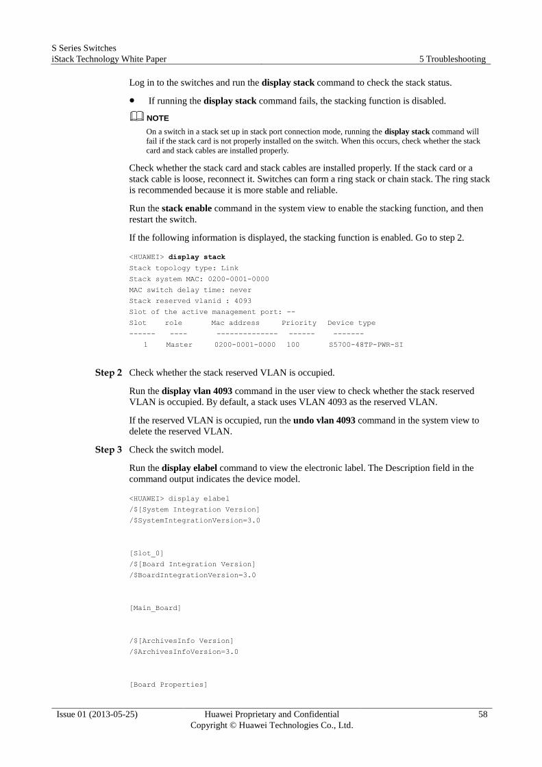
S Series Switches
iStack Technology White Paper 5 Troubleshooting
Issue 01 (2013-05-25) Huawei Proprietary and Confidential
Copyright © Huawei Technologies Co., Ltd.
58
Log in to the switches and run the display stack command to check the stack status.
If running the display stack command fails, the stacking function is disabled.
NOTE
On a switch in a stack set up in stack port connection mode, running the display stack command will
fail if the stack card is not properly installed on the switch. When this occurs, check whether the stack
card and stack cables are installed properly.
Check whether the stack card and stack cables are installed properly. If the stack card or a
stack cable is loose, reconnect it. Switches can form a ring stack or chain stack. The ring stack
is recommended because it is more stable and reliable.
Run the stack enable command in the system view to enable the stacking function, and then
restart the switch.
If the following information is displayed, the stacking function is enabled. Go to step 2.
<HUAWEI> display stack
Stack topology type: Link
Stack system MAC: 0200-0001-0000
MAC switch delay time: never
Stack reserved vlanid : 4093
Slot of the active management port: --
Slot role Mac address Priority Device type
------ ---- -------------- ------ -------
1 Master 0200-0001-0000 100 S5700-48TP-PWR-SI
Step 2 Check whether the stack reserved VLAN is occupied.
Run the display vlan 4093 command in the user view to check whether the stack reserved
VLAN is occupied. By default, a stack uses VLAN 4093 as the reserved VLAN.
If the reserved VLAN is occupied, run the undo vlan 4093 command in the system view to
delete the reserved VLAN.
Step 3 Check the switch model.
Run the display elabel command to view the electronic label. The Description field in the
command output indicates the device model.
<HUAWEI> display elabel
/$[System Integration Version]
/$SystemIntegrationVersion=3.0
[Slot_0]
/$[Board Integration Version]
/$BoardIntegrationVersion=3.0
[Main_Board]
/$[ArchivesInfo Version]
/$ArchivesInfoVersion=3.0
[Board Properties]
S Series Switches
iStack Technology White Paper 5 Troubleshooting
Issue 01 (2013-05-25) Huawei Proprietary and Confidential
Copyright © Huawei Technologies Co., Ltd.
59
BoardType=CX22EMGEB
BarCode=21023518320123456789
Item=02351832
Description=Quidway S5700-48TP-PWR-SI,LS5ZC48CM,S5700-48TP-PWR-SI Mainframe
Manufactured=2009-02-05
VendorName=Huawei
IssueNumber=
CLEICode=
BOM=
If the switch is not of a different model from other switches, replace the switch.
If the switches have the same model, go to step 4.
Step 4 Check that the correct electronic label has been loaded to the switch.
Run the display elabel command to view the electronic label.
If all fields under [Board Properties] are empty, no electronic label is loaded to the
switch. Replace the switch.
<HUAWEI> display elabel
/$[System Integration Version]
/$SystemIntegrationVersion=3.0
[Slot_0]
/$[Board Integration Version]
/$BoardIntegrationVersion=3.0
[Main_Board]
/$[ArchivesInfo Version]
/$ArchivesInfoVersion=3.0
[Board Properties]
BoardType=
BarCode=
Item=
Description=
Manufactured=
VendorName=
IssueNumber=
CLEICode=
BOM=
If fields under [Board Properties] are not empty, the electronic label has been loaded to
the switch. Go to step 5.
<HUAWEI> display elabel
/$[System Integration Version]
/$SystemIntegrationVersion=3.0
[Slot_0]

S Series Switches
iStack Technology White Paper 5 Troubleshooting
Issue 01 (2013-05-25) Huawei Proprietary and Confidential
Copyright © Huawei Technologies Co., Ltd.
60
/$[Board Integration Version]
/$BoardIntegrationVersion=3.0
[Main_Board]
/$[ArchivesInfo Version]
/$ArchivesInfoVersion=3.0
[Board Properties]
BoardType=CX22EMGEB
BarCode=21023518320123456789
Item=02351832
Description=Quidway S5700-48TP-PWR-SI,LS5ZC48CM,S5700-48TP-PWR-SI Mainframe
Manufactured=2009-02-05
VendorName=Huawei
IssueNumber=
CLEICode=
BOM=
Step 5 Check the electronic label of the stack card.
NOTE
Perform this step only on switches that set up a stack using stack cards.
Run the display elabel slot slot-number sub-card-number command to check the electronic
label of the stack card.
In the command, slot slot-number specifies the stack ID, which can be obtained from the
display stack command output. The subcard-number value is always 2 for a stack card. For
example, to view the stack card electronic label on a switch with stack ID 0, run the display
elabel slot 0 2 command.
If all fields under [Board Properties] are empty, the stack card does not function properly.
Replace the stack card.
<HUAWEI> display elabel slot 0 2
/$[System Integration Version]
/$SystemIntegrationVersion=3.0
[Slot_0]
/$[Board Integration Version]
/$BoardIntegrationVersion=3.0
[Main_Board]
/$[ArchivesInfo Version]
/$ArchivesInfoVersion=3.0
[Board Properties]
S Series Switches
iStack Technology White Paper 5 Troubleshooting
Issue 01 (2013-05-25) Huawei Proprietary and Confidential
Copyright © Huawei Technologies Co., Ltd.
61
BoardType=
BarCode=
Item=
Description=
Manufactured=
VendorName=
IssueNumber=
CLEICode=
BOM=
If fields under [Board Properties] are not empty, go to step 6.
<HUAWEI> display elabel slot 0 2
/$[System Integration Version]
/$SystemIntegrationVersion=3.0
[Slot_0]
/$[Board Integration Version]
/$BoardIntegrationVersion=3.0
[Main_Board]
/$[ArchivesInfo Version]
/$ArchivesInfoVersion=3.0
[Board Properties]
BoardType=CX22ETPC
BarCode=210235000c0120081008
Item=0235000c
Description=CX22ETPC for S5700 HindCard
Manufactured=2008-11-14
VendorName=Huawei
IssueNumber=
CLEICode=
BOM=
Step 6 Check that stack cables are correctly connected.
NOTE
Perform this step only on switches that set up a stack using service interfaces.
If the switch uses service ports and stack ports, check the configuration of the stack ports.
Run the display stack port [ configuration ] [ slot slot-id ] command to check the
configuration of stack ports.
Compare the ports displayed in the command output with the ports used for stack connection.
<HUAWEI> display stack port
*down : administratively down
Logic Port Phy Port Online Status
----------------------------------------------------------------------------
S Series Switches
iStack Technology White Paper 5 Troubleshooting
Issue 01 (2013-05-25) Huawei Proprietary and Confidential
Copyright © Huawei Technologies Co., Ltd.
62
stack-port0/1 XGigabitEthernet0/0/1 present up
stack-port0/2 XGigabitEthernet0/0/3 present *down
stack-port3/1 XGigabitEthernet3/0/1 present down
XGigabitEthernet3/0/2 present down
stack-port3/2 XGigabitEthernet3/0/3 present up
stack-port4/1 XGigabitEthernet4/0/1 present up
stack-port4/2 XGigabitEthernet4/0/3 present up
stack-port8/1 XGigabitEthernet8/0/1 present up
stack-port8/2 XGigabitEthernet8/0/3 present up
If the ports displayed in the command output are different from the ports used for stack
connection, reconnect ports.
If the ports displayed in the command output are the same as the ports used for stack
connection, go to step 7.
Step 7 Check that the stack cards and stack cables are functioning properly.
Check the status of physical member interfaces in the display stack port command
output. If all the member ports are Up, go to step 8.
If a member port is Down, check whether the switch connected to the port has been
powered off or is restarting. If so, check the port status after the remote switch restarts. If
not, replace the stack card on the local switch or the stack cable on this port.
If the fault persists, go to step 8.
Step 8 Collect the following information and contact Huawei technical support personnel.
Results of the preceding troubleshooting procedure
Configuration file, logs, and alarms of the device
----End
Relevant Alarms A stack port goes Up: FSP_1.3.6.1.4.1.2011.5.25.183.1.22.1 hwStackLinkUp
A stack port goes Down: FSP_1.3.6.1.4.1.2011.5.25.183.1.22.2 hwStackLinkDown
A switch has joined a stack: FSP_1.3.6.1.4.1.2011.5.25.183.1.22.6
hwStackStackMemberAdd
A switch has left a stack: FSP_1.3.6.1.4.1.2011.5.25.183.1.22.7
hwStackStackMemberLeave
Logical ports with the same ID on two switches are connected:
ECM_1.3.6.1.4.1.2011.5.25.183.1.22.9 hwStackLogicStackPortLinkErr
Physical ports of the same logical port are connected differently:
ECM_1.3.6.1.4.1.2011.5.25.183.1.22.10 hwStackPhyStackPortLinkErr
5.2 A Stack Cannot Run Properly Because One Member Switch Becomes Faulty
When faults often occur on a member switch of a stack, the stack cannot run properly. To
ensure the reliability of other running member switches, you need to isolate the member
switch from the stack. This isolation mode applies only to service port connection but not to
stack card connection because the number of stack port limitations of stack cards.
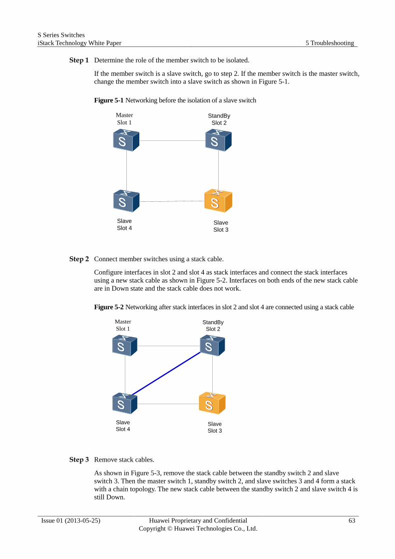
S Series Switches
iStack Technology White Paper 5 Troubleshooting
Issue 01 (2013-05-25) Huawei Proprietary and Confidential
Copyright © Huawei Technologies Co., Ltd.
63
Step 1 Determine the role of the member switch to be isolated.
If the member switch is a slave switch, go to step 2. If the member switch is the master switch,
change the member switch into a slave switch as shown in Figure 5-1.
Figure 5-1 Networking before the isolation of a slave switch
Slave
Slot 4
Master
Slot 1
Slave
Slot 3
StandBy
Slot 2
Step 2 Connect member switches using a stack cable.
Configure interfaces in slot 2 and slot 4 as stack interfaces and connect the stack interfaces
using a new stack cable as shown in Figure 5-2. Interfaces on both ends of the new stack cable
are in Down state and the stack cable does not work.
Figure 5-2 Networking after stack interfaces in slot 2 and slot 4 are connected using a stack cable
Slave
Slot 4
Master
Slot 1
Slave
Slot 3
StandBy
Slot 2
Step 3 Remove stack cables.
As shown in Figure 5-3, remove the stack cable between the standby switch 2 and slave
switch 3. Then the master switch 1, standby switch 2, and slave switches 3 and 4 form a stack
with a chain topology. The new stack cable between the standby switch 2 and slave switch 4 is
still Down.

S Series Switches
iStack Technology White Paper 5 Troubleshooting
Issue 01 (2013-05-25) Huawei Proprietary and Confidential
Copyright © Huawei Technologies Co., Ltd.
64
Remove the stack cable between slave switches 3 and 4. Then the new stack cable becomes
Up, and the master switch 1, standby switch 2, and slave switch 3 form a stack with a ring
topology, as shown in Figure 5-4.
Figure 5-3 Removing the stack cable between standby switch 2 and slave switch 3
Slave
Slot 4
Master
Slot 1
Slave
Slot 3
StandBy
Slot 2
Figure 5-4 Networking after the isolation of a slave switch
Slave
Slot 4
Master
Slot 1
Slave
Slot 3
StandBy
Slot 2
----End

S Series Switches
iStack Technology White Paper 6 FAQ
Issue 01 (2013-05-25) Huawei Proprietary and Confidential
Copyright © Huawei Technologies Co., Ltd.
65
6 FAQ
6.1 Can I Log In to a Standby or Slave Switch from Its Console Port or Management Interface?
You can log in to a stack from the console port or management interface of any member
switch to manage the stack.
6.2 How Can I Determine Which Member Switch Is the Master of a Stack Without Logging In to the Stack?
A device has a mode switching button, which can set the device mode. Press this button on the
device to set the device mode to stack. If the Stack indicator on the device blinks, this device
is the master of the stack.
6.3 How Can I Check the Stack ID of a Box Switch Through Indicators?
Press the mode switching button on the front panel of the switch. When the mode switching
button turns red, the port indicator on the front panel indicates the stack ID of the switch.
When checking the stack ID of a box switch, note the following:
Non-master switch:
− Switch with the stack ID ranging from 1 to 8: The sequence number of the port
indicator that is steady on indicates the stack ID of the switch. For example, if the
first port indicator is steady on, the stack ID is 1. If the second port indicator is steady
on, the stack ID is 2.
− Switch with stack ID 0: The number of port indicators that are steady on indicates the
number of member devices supported by the product. For example, if the first nine
port indicators are steady on, the product supports nine member switches in a stack,
and the stack ID of the local switch is 0.
Master switch: The stack ID indicator is blinking. The method to check the stack ID on
the master switch is the same as that used on non-master switches.
S Series Switches
iStack Technology White Paper 6 FAQ
Issue 01 (2013-05-25) Huawei Proprietary and Confidential
Copyright © Huawei Technologies Co., Ltd.
66
6.4 What Is the Bandwidth Limitation on the S5700-SI&S5700-EI?
The S5700-SI&S5700-EI subcards in the front slot and rear slot use the same chip that
provides 4x10 Gbit/s bandwidth.
A stack card can be used with a 2x10G subcard. Two stack interfaces on the stack card
occupy 20 Gbit/s bandwidth, and the 2x10G subcard occupies 20 Gbit/s. A stack card cannot
be used with a 4x10GE subcard. The 10GE interfaces on the 4x10GE subcard are actually
10GE interfaces with their rates limited, so the actual bandwidth of the subcard is 4x10 Gbit/s.
This subcard occupies all the 4x10 Gbit/s bandwidth of the chip, so there is no available
bandwidth for the stack card.