ISSUED BY RPP-WTPPDC Rev. I CORROSION ... bof-009...ISSUED BY RPP-WTPPDC 24590-BOF-NlD-DEP-00007...
14
ISSUED BY RPP-WTPPDC 24590-BOF-NlD-DEP-00007 Rev. I I CORROSION EVALUATION DEP-COND-00001, 2, & 3 Ill 1111111111111111111111111 R11873323 DEP Evaporator Primary Condenser, Inter-Condenser, and After-Condenser Contents of this document are Dangerous Waste Permit affecting Results Materials Considered Material Acceptable Material (UNS No.) Carbon Steel Type 304L (S30403) X Type 316L(S31603) X Al-6XN® 6% Mo (N08367) X Hastellov® C22® (N06022) X Recommended Material Type Shell & Tubes: Type 304 (max 0.030% C; dual certified) Tubes shall be seamless Minimum Corrosion Allowance Shell side & heads: 0.040 inch (includes 0.024 inch corrosion allowance and 0.004 inch erosion allowance; Seamless tubes: 0.0 inch Inputs and References • Operating temperature (°F) (inlet) (nom/max): I 09/143 (24590-BOF-MEC-DEP-0000 I) • Operating temperature (°F) (outlet) (nom/max): I 09/109 (24590-BOF-MEC-DEP-0000 I) • Solids concentration (wt%): 0 (24590-BOF-RPT-PR-15-001) • Design corrosion allowance, shell (inch): 0.040 (24590-WTP-M0C-50-00004) • Uniform corrosion allowance, shell (inch): 0.024 (24590-WTP-M0E-50-00012) • Uniform erosion allowance, shell (inch): 0.004 (24590-WTP-M0C-50-00004) • Design corrosion allowance, tubes (inch): 0.0 (24590-WTP-GPG-M-047) • Location: Room E-0102 (24590-BOF-Pl-25-00001) • Operating conditions are as stated in the applicable section of Direct Feed LAW Process Corrosion Data (24590-BOF-RPT-PR-15-001) Assumptions and Justification (refer to Section 19-References) • Source data presented on the Process Corrosion Datasheet (PCDS) are conservative with respect to corrosion. 3 Operating Restrictions • To protect against localized corrosion in the condensers and transfer piping, develop procedure to bring the condensers contents to within the limits defined for Type 304L in 24590-WTP-RPT-M-11-002, WTP Materials Locali=ed Corrosion Design Limits, in the event that temperature, pH, or chloride concentration exceeds those limits. • Develop a procedure to control, at a minimum, cleaning, rinsing, and flushing of condensers. • Develop procedure to control lay-up and storage; includes both before plant is operational and during inactive periods after start-up. • Procedures are to be reviewed and accepted by MET prior to use. Concurrence TD Operations Checked evlewed I.ti -z_d 1. l/,io/4t Revised sect 17 to discuss DFLA W l'&£e!!!'!.!!!'1s PIBOD properties Originator ' 8y.A.Rangus•apnmg<JS . I Orglwnos-.1 OrgNaTleMET By:DebbleAdle.-·dladle, 1 ~· Jan15.201S --- Minor editorial changes OrgNameMET J..,12.2018.43,lr,m -J-,11.2018 APRangus RBDavis TErwin 0 Initial Issue DLAdler APRangus RBDavis TErwin REV DATE REASON FOR REVISION ORIGINATE CHECK REVIEW APPROVE Sheet: 1 of 14
Transcript of ISSUED BY RPP-WTPPDC Rev. I CORROSION ... bof-009...ISSUED BY RPP-WTPPDC 24590-BOF-NlD-DEP-00007...

ISSUED BY RPP-WTPPDC 24590-BOF-NlD-DEP-00007
Rev. I I CORROSION EVALUATION
DEP-COND-00001, 2, & 3 Ill 1111111111111111111111111
R11873323 DEP Evaporator Primary Condenser, Inter-Condenser, and After-Condenser
Contents of this document are Dangerous Waste Permit affecting
Results
Materials Considered
Material Acceptable Material (UNS No.)
Carbon Steel Type 304L (S30403) X Type 316L(S31603) X Al-6XN® 6% Mo (N08367) X Hastellov® C22® (N06022) X
Recommended Material Type Shell & Tubes: Type 304 (max 0.030% C; dual certified) Tubes shall be seamless
Minimum Corrosion Allowance Shell side & heads: 0.040 inch (includes 0.024 inch corrosion allowance and 0.004 inch erosion allowance;
Seamless tubes: 0.0 inch
Inputs and References • Operating temperature (°F) (inlet) (nom/max): I 09/143 (24590-BOF-MEC-DEP-0000 I) • Operating temperature (°F) ( outlet) (nom/max): I 09/109 (24590-BOF-MEC-DEP-0000 I) • Solids concentration (wt%): 0 (24590-BOF-RPT-PR-15-001) • Design corrosion allowance, shell (inch): 0.040 (24590-WTP-M0C-50-00004) • Uniform corrosion allowance, shell (inch): 0.024 (24590-WTP-M0E-50-00012) • Uniform erosion allowance, shell (inch): 0.004 (24590-WTP-M0C-50-00004) • Design corrosion allowance, tubes (inch): 0.0 (24590-WTP-GPG-M-047) • Location: Room E-0102 (24590-BOF-Pl-25-00001) • Operating conditions are as stated in the applicable section of Direct Feed LAW Process Corrosion Data (24590-BOF-RPT-PR-15-001)
Assumptions and Justification (refer to Section 19-References) • Source data presented on the Process Corrosion Datasheet (PCDS) are conservative with respect to corrosion. 3
Operating Restrictions • To protect against localized corrosion in the condensers and transfer piping, develop procedure to bring the condensers contents to
within the limits defined for Type 304L in 24590-WTP-RPT-M-11-002, WTP Materials Locali=ed Corrosion Design Limits, in the event that temperature, pH, or chloride concentration exceeds those limits.
• Develop a procedure to control, at a minimum, cleaning, rinsing, and flushing of condensers. • Develop procedure to control lay-up and storage; includes both before plant is operational and during inactive periods after start-up. • Procedures are to be reviewed and accepted by MET prior to use.
Concurrence TD Operations
Checked ✓ 1 evlewed
I.ti -z_d 1. l/,io/4t Revised sect 17 to discuss DFLA W l'&£e!!!'!.!!!'1s
PIBOD properties Originator ' 8y.A.Rangus•apnmg<JS .
I Orglwnos-.1 OrgNaTleMET By:DebbleAdle.-·dladle, 1~· Jan15.201S ---
Minor editorial changes OrgNameMET J..,12.2018.43,lr,m
-J-,11.2018 APRangus RBDavis TErwin 0 Initial Issue DLAdler APRangus RBDavis TErwin
REV DATE REASON FOR REVISION ORIGINATE CHECK REVIEW APPROVE
Sheet: 1 of 14

24590-BOF-NlD-DEP-00007 Rev. I
CORROSION EVALUATION
Please note that source, special nuclear and byproduct materials, as defined in the Atomic Energy Act of 1954 (AEA), are regulated at the U.S. Department of Energy (DOE) facilities exclusively by DOE acting pursuant to its AEA authority. DOE asserts, that pursuant to the AEA, it has sole and exclusive responsibility and authority to regulate source, special nuclear, and byproduct materials at DOEowned nuclear facilities. Information contained herein on radionuclides is provided for process description purposes only.
DEP-COND-00001, 2, & 3: Sheet: 2 of14
This bound document contains a total of 14 sheets.

CORROSION EVALUATION
Corrosion/Erosion Detailed Discussion
24590-BOF-NlD-DEP-00007 Rev.1
The evaporator primary condenser (DEP-COND-0000 I) is the main condenser for the DEP evaporator separator vessel. The condensate from the top ofDEP-EV AP-00001 is condensed in the shell and tube condenser on the shell side using a secondary cooling water loop on the tube side. The condensate is either pumped to DEP-VSL-00004A/B or returned to the evaporator separator vessel as a reflux stream. A portion of the condensate is also filtered and used to spray off the evaporator demister pads.
The first stage ejector (DEP-EJCTR-00001) is used to draw vapor from the DEP evaporator vessel into DEP-COND-00001 to create a vacuum in the DEP evaporator vessel.
The evaporator inter condenser (DEP-COND-00002) and after condenser (DEP-COND-00003) work with the steam ejectors to create a vacuum in DEP-EVAP-0000 I. The second stage ejector (DEP-EJCTR-00002) is used to draw vapor from DEP-COND-00002 then push material into the after-condenser (DEP-COND-00003) where the remaining non-condensable gas is drawn off into the vessel vent header. DEP-COND-00002 and DEP-COND-00003 are cooled by a secondary cooling water system that uses plant cooling water (PCW) to condense residual water vapor. The condensate from the condensers flows to DEP-COND-00001 boot from where it is pumped to the overhead sampling vessels (DEP-VSL-00004 A/8).
1 General/Uniform Corrosion Analysis
a Background General corrosion or uniform corrosion is corrosion that is distributed uniformly over the surface of a material without appreciable localization. This leads to relatively uniform thinning on sheet and plate materials and general thinning on one side or the other ( or both) for pipe and tubing. It is recognized by a roughening of the surface and by the presence of corrosion products. The mechanism of the attack is an electrochemical process that takes place at the surface of the material. Differences in composition or orientation between small areas on the metal surface create anodes and cathodes that facilitate the corrosion process.
b Component-Specific Discussion Shell side liquid and vapors are clean, similar to demineralized water, condensed from steam and gases off of the DEP evaporator. The cooling water side is fed by plant cooling water. The water is relatively clean and treated with corrosion inhibitors, and is free of aggressive ions and silt. At temperatures up to 150°F, either type 304L or type 316L is expected to be sufficiently resistant to the waste solution. Under the stated conditions, the uniform corrosion rate will be low.
2 Pitting Corrosion Analysis
Pitting is localized corrosion of a metal surface that is confined to a point or small area and takes the form of cavities. Chloride is known to cause pitting in acid and neutral solutions. Normally the condensers operate at 109 °F (143 °F max) at a pH of7.0; however, the system is operated such that conditions do not promote localized corrosion.
The expected chemistry and temperature for the condensers fall within the limits for localized corrosion established for 300 series stainless steel in Table 1-2 of WTP Materials Localized Corrosion Design Limits, 24590-WTP-RPT-M-11-002. For convenience, this comparison is documented on page 6 of this corrosion evaluation.
3 Crevice Corrosion Analysis
Crevice corrosion is a form of localized corrosion of a metal or alloy surface at, or immediately adjacent to, an area that is shielded from full exposure to the environment because of close proximity of the metal or alloy to the surface of another material or an adjacent surface of the same metal or alloy. Crevice corrosion is similar to pitting in mechanism.
Crevices in these condensers are limited by the design and fabrication practice. All welding uses butt welds, and crevices associated with internals are minimal. With the stated operating conditions, either Type 304L or Type 316L is acceptable.
The chemistry and operating conditions in these condensers fall within the limits established for either Type 304L or Type 316L in Table 1-2 of24590-WTP-RPT-M-l l-002.
4 Stress Corrosion Cracking Analysis
Stress corrosion cracking (SCC) is the cracking of a material produced by the combined action of corrosion and sustained tensile stress (residual or applied). The exact amount of chloride required to cause stress corrosion cracking is unknown. In part this is because the amount varies with temperature, metal sensitization, and the environment; also, chloride tends to concentrate under heat transfer conditions, by evaporation, and electrochemically during a corrosion process.
The chemistry and operating conditions in these condensers fall within the limits established for either Type 304L or Type 316L in Table 1-2 of24590-WTP-RPT-M-11-002.
DEP-COND-00001, 2, & 3: Sheet: 3 of14

CORROSION EVALUATION
5 End Grain Corrosion Analysis
24590-BOF-NlD-DEP-00007 Rev. I
End grain corrosion is preferential corrosion which occurs along the cold working direction of wrought stainless steels that is exposed to highly oxidizing acidic conditions. End grain corrosion is exclusive to metallic product forms with exposed end grains from shearing or mechanical cutting. Conditions which lead to end grain corrosion are not present in this component; therefore, end grain corrosion is not a concern.
6 Weld Corrosion Analysis
The welds used in the fabrication will follow the WTP specifications and standards for quality workmanship. The materials selected for this fabrication are compatible with the weld filler metals and ASME/ A WS practice. Using the welding practices specified for the project, there should not be gross micro-segregation, precipitation of secondary phases, formation of unmixed zones, or volatilization of the alloying elements that could lead to localized corrosion of the weld. The low carbon materials specified for WTP prevent base metal sensitization during welding. Controls on the cover gas, heat input, and interpass temperature limit the heat tint. Corrosion at welds is not considered a problem in the proposed environment. No additional allowance is made for weld bead corrosion.
7 Microbiologically Influenced Corrosion Analysis
Microbiologically influenced corrosion (MIC) refers to corrosion affected by the presence or activity, or both, of microorganisms. The proposed operating conditions are suitable for microbial growth. However, treated process water is used and water quality is controlled to prevent MIC.
8 Fatigue/Corrosion Fatigue Analysis
Fatigue is the process of progressive localized permanent structural change occurring in a material subjected to fluctuating stresses at less than the ultimate tensile strength of the material. Corrosion fatigue is the process wherein a metal fractures prematurely under conditions of simultaneous corrosion and repeated cyclic loading at lower stress levels or fewer cycles than would be required to cause fatigue of that metal in the absence of the corrosive environment. The condensers won't experience sufficient thermal or mechanical cycles to lead to fatigue or corrosion fatigue.
9 Vapor Phase Corrosion Analysis
Conditions in the vapor phase and at the vapor/liquid interface can be significantly different than those present in the liquid phase. vapor space corrosion is self-limiting due to the formation of a passive film. Also, the layers of deposited corrosion product on top of the passive film act as barriers that reduce mass transport necessary for corrosion. Corrosion rates of materials exposed to vapors in the headspace are never greater than the corrosion during immersion service. The corrosion at the liquid air interface (LAI) interface is an oxygen concentration cell resulting from the alternate wetting and drying. Components that do not maintain a constant liquid level do not tend to form a surface crust and are not expected to be susceptible to LAI corrosion. Corrosion at the LAI could be similar to immersion service and not usually greater. WTP components also have the protective passive film at the LAI which reduces corrosion and the liquid level is constantly changing. As compared to the corrosion in the immersion section, the corrosion rates in the vapor space are much lower. Vapor phase corrosion is not a concern.
10 Erosion Analysis
Erosion is the progressive loss of material from a solid surface resulting from mechanical interaction between that surface and a fluid, a multi-component fluid, or solid particles carried with the fluid. Velocities within the condensers are expected to be below 12 ft/s. The solids concentration is at or near 0 wt% based on negligible solids being present in the evaporator overheads. Erosion allowance of0.004 inch for Type 304L and 3 l 6L stainless steel components with solids content less than 2 wt%.at low velocities is based on 24590-WTPM0C-50-00004, Wear Allowance for WTP Waste Slurry Systems. The recommended general erosion wear allowance provides sufficient protection for erosion of the condenser shells. The margin in the erosive wear allowances used above is contained in the referenced calculation (24590-WTP-M0C-50-00004 ).
Conditions do not suggest that localized erosion will occur; therefore, no localized erosion allowance is necessary for the condensers.
11 Galling of Moving Surfaces Analysis
Where two metals are moving in contact with each other without lubrication, there is a risk of damage to their surfaces. No moving unlubricated surfaces are present within the condensers; therefore, galling is not a concern.
12 Fretting/Wear Analysis
Fretting corrosion refers to corrosion damage caused by a slight oscillatory slip between two surfaces. Similar to galling but at a much smaller movement, the corrosion products and metal debris break off and act as an abrasive between the surfaces, producing a classic three-body wear problem. This damage is induced under load and repeated relative surface motion. Generally, design of the condensers will prevent damage from fretting. However, tube to tube sheet fretting corrosion is possible when flow is directed to under-supported tubes. Design actions should be implemented to prevent direct impingement of inlet tubing.
DEP-COND-00001, 2, & 3: Sheet: 4 of 14
CORROSION EVALUATION 13 Galvanic Corrosion Analysis
24590-BOF-NlD-DEP-00007 Rev.1
Galvanic corrosion is accelerated corrosion caused by the potential difference between the two dissimilar metals in an electrolyte. A potential difference of more than 200 m V is needed for a sufficient driving force to initiate galvanic corrosion. One material becomes the anode and the other the cathode. Corrosion occurs on the anode material at the interface where the potential gradient is the greatest. potential difference for any combination of austenitic stainless steels, 6% Mo and, the nickel alloys is not sufficient for galvanic currents to overcome the passive protective film. For such alloys, there is negligible potential difference, so galvanic corrosion is not a concern.
14 Cavitation Analysis
Cavitation is the formation and rapid collapse of cavities or bubbles of vapor or gas within a liquid resulting from mechanical or hydrodynamic forces. Cavitation is typically associated with pumps and orifice plates. Cavitation is not a concern for the condensers.
15 Creep Analysis
Creep is time-dependent strain occurring under stress and is described as plastic flow, yielding at stresses less than the yield strength. Creep is only experienced in plants operating at high temperatures. Temperatures much greater than one half the absolute melting temperature of the alloy are necessary for thermally activated creep to become a concern. The condenser operating and design temperatures are too low to lead to creep; therefore, creep is not a concern.
16 Inadvertent Nitric Acid Addition
At this time, the design does not provide for the regular use of nitric acid reagent in this system.
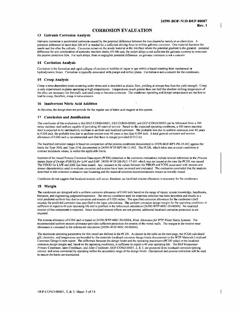
17 Conclusion and Justification
The conclusion of this evaluation is that DEP-COND-00001, DEP-COND-00002, and DEP-COND-00003 can be fabricated from a 300 series stainless steel and are capable of providing 40 years of service. Based on the expected operating conditions, a 300 series stainless steel is expected to be satisfactorily resistant to uniform and localized corrosion. The probable loss due to uniform corrosion over 40 years is 0.024 inch; the probable loss due to uniform erosion over 40 years is less than 0.004 inch. A total general corrosion and erosion allowance of0.040 inch is recommended such that there is margin provided (0.012 in).
The localized corrosion margin is based on comparison of the process conditions documented in 24590-BOF-RPT-PR-15-001 against the limits for Type 304L and Type 3 I 6L documented in 24590-WTP-RPT-M-11-002. The PCDS, which takes into account conditions at contract maximum values, is within the applicable limits.
Sections of the issued Process Corrosion Data report (PCDS) (attached to the corrosion evaluation) include several references to the Process Inputs Basis of Design (PIBOD)for LAW and EMF, 24590-WTP-DB-PET-17-001 which was not issued at the time the PCDS was issued. The PIBOD for LAW and EMF has been issued. Any variance in the values between the PIBOD and PCDS associated with streams and stream characteristics used to evaluate corrosion and erosion have been reviewed and evaluated. The evaluation concluded that the analysis described in this corrosion evaluation was bounding and the material selection recommendations remain as initially issued.
Conditions do not suggest that localized erosion will occur; therefore, no localized erosion allowance is necessary for the condensers.
18 Margin
The condensers are designed with a uniform corrosion allowance of0.040 inch based on the range of inputs, system knowledge, handbooks, literature, and engineering judgment/experience. The service conditions used for materials selection has been described and results in a total predicted uniform loss due to corrosion and erosion of0.028 inches. The specified corrosion allowance for the condensers shell exceeds the predicted corrosion loss specified in the input calculations. The uniform corrosion design margin for the operating conditions is sufficient to expect a 40 year operating life and is justified in the referenced calculation (24590-WTP-M0C-50-00004 ). No localized erosion of this component is expected. Since localized erosion effects are not present, additional localized corrosion protection is not required.
The erosion allowance of0.004 inch is based on 24590-WTP-M0C-50-00004, Wear Allowance for WTP Waste Slurry Systems. The recommended uniform erosion allowance provides sufficient protection for erosion of the vessel walls. The margin in the erosive wear allowance is contained in the referenced calculation (24590-WTP-M0C-50-00004).
The maximum operating parameters for this vessel are defined in the PCDS. As shown in the table on the next page, the PCDS calculated pH, chemistry, and temperature are bounded by the materials localized corrosion design limits documented in the WTP Materials Localized Corrosion Design Limits report. The difference between the design limits and the operating maximums (PCDS value) is the localized corrosion design margin and, based on the operating conditions, is sufficient to expect a 40 year operating life. The DEP Evaporator Primary Condenser, Inter-Condenser, and After-Condenser, DEP-COND-0000 I, 2, & 3, are protected from localized corrosion (pitting, crevice, and stress corrosion) by operating within the acceptable range of the design limits. Operational and process restriction will be used to ensure the limits are maintained.
DEP-COND-00001, 2, & 3: Sheet: 5 of 14

24590-BOF-NlD-DEP-00007 Rev.1
CORROSION EVALUATION
MATERIALS LOCALIZED CORROSION DESIGN LIMITS-Type 304L/316L
Temuerature .ltl! T:i:ue304L Tne316L OF Chloride m Chloride
DESIGN LIMIT 150 max 5 to 10 150 max 300 max
Condensate to DEP-VSL-00004A/B 143 7.0 29 29
DEP04
Inlet Vessel to DEP-COND-00001 Temuerature
.ltl! T:i:ue304L
OF Chloride m
DESIGN LIMIT 150 max 5 to 10 150 max 300max
Evaporator overheads From DEP-EVAP-00001 109-143 NA NR NR
(DEP19) NR-not reported
Inlet vessels to DEP-COND-00001 based on 24590-BOF-RPT-PR-15-001, Section 4.4, and Figure 5.
I. Design limits - 24590-WTP-RPT-M-11-002, WTP Materials Localized Corrosion Design Limits 2. DEP-EVAP-00001 overheads (DEP19) --24590-BOF-RPT-PR-15-001, Direct Feed LAW Process Corrosion Data, Section
4.4.3.1.3. l
DEP-COND-00001, 2, & 3: Sheet: 6 of 14
m

CORROSION EVALUATION
19 References:
24590-BOF-NlD-DEP-00007 Rev.1
1. 24590-BOF-MEC-DEP-00001, DFLA W EMF Process System (DEP) Evaporator Operating Conditions, Heating/Cooling Duty, and Utility Requirements.
2. 24590-BOF-Pl-25-00001, Balance of Facilities LAW Ejjluent Process Bldg & LAW Ejjluent Drain Tank Bldg General Arrangement Plan at Elev 0 Ft - 0 In.
3. 24590-BOF-RPT-PR-15-001, Direct Feed LAW Process Corrosion Data. 4. 24590-WTP-DB-PET-17-001, Process Inputs Basis of Design (PIBOD)for LAW and EMF 5. 24590-WTP-GPG-M-047, Preparation of Corrosion Evaluations. 6. 24590-WTP-M0C-50-00004, Wear Allowance for WTP Waste Slurry Systems with ECCN 24590-WTP-M0E-50-00012. 7. 24590-WTP-RPT-M-11-002, WTP Vessel Locali=ed Corrosion Limit Analysis Report.
Additional Reading • 24590-BOF-MED-DEP-00004, Mechanical Data Sheet- DEP-COND-00001 • 24590-BOF-MED-DEP-00005, Mechanical Data Sheet- DEP-COND-00002 • 24590- BOF-MED-DEP-00006, Mechanical Data Sheet- DEP-COND-00003 • 24590-WTP-RPT-M-04-0008, Rev. 3, Evaluation Of Stainless Steel Wear Rates In WTP Waste Streams At Low Velocities • Blackbum, LO to PG Johnson, Internal Memo, Westinghouse Hanford Co, Evaluation of240-AR Chloride Limit, August 15, 1991. • Danielson, MJ & SG Pitman, 2000, Corrosion Tests of 316L and Haste/lay C-22 in Simulated Tank Waste Solutions, PNWD-3015
(BNFL-RPT-019, Rev 0), Pacific Northwest Laboratory, Richland WA • Davis, JR (Ed), 1987, Corrosion, Vol 13, In "Metals Handbook", ASM International, Metals Park, OH 44073 • Davis, JR (Ed), 1994, Stainless Steels, In ASM Metals Handbook, ASM International, Metals Park, OH 44073 • Dillon, CP (Nickel Development Institute), Personal Communication to JR Divine (ChemMet, Ltd., PC), 3 Feb 2000. • Divine, JR, 1986, Letter to A.J. Diliberto, Reports of Experimentation, Battelle, Pacific Northwest Laboratories, Richland, WA 99352 • Hamner, NE, 1981, Corrosion Data Survey, Metals Section, 5th Ed, NACE International, Houston, TX • Jones, RH (Ed.), 1992, Stress-Corrosion Cracking, ASM International, Metals Park, OH 44073 • Koch, GH, 1995, Locali=ed Corrosion in Halides Other Than Chlorides, MTI Pub
0
No. 41, Materials Technology Institute of the Chemical Process Industries, Inc, St Louis, MO 63141
• Ohl, PC to PG Johnson, Internal Memo, Westinghouse Hanford Co, Technical Bases for Cl- and pH Limits for Liquid Waste Tank Cars, MA: PCO:90/01, January 16, 1990.
• Phull, BS, WL Mathay, & RW Ross, 2000, Corrosion Resistance of Duplex and 4-6% Mo-Containing Stainless Steels i FGD Scrubber Absorber Slurry Environments, Presented at Corrosion 2000, Orlando, FL, March 26-31, 2000, NACE International, Houston TX 77218.
• Sedriks, AJ, 1996, Corrosion of Stainless Steels, John Wiley & Sons, Inc., New York, NY 10158 • Uhlig, HH, 1948, Corrosion Handbook, John Wiley & Sons, New York, NY 10158 • Van Delinder, LS (Ed), 1984, Corrosion Basics, NACE International, Houston, TX 77084
DEP-COND-00001, 2, & 3: Sheet: 7 of 14

CORROSION EVALUATION
24590-80 F-N 1 D-D EP-00007 Rev. 1
PROCESS CORROSION DATA SHEET (extract)
Component(s) (Name/ID #) DEP Evaporator Primary, Inter-, and After-Condens,
Facility
In Black Cell?
Chemicals Cations (ppm)
Al. 3 (Aluminum)
Fe•3 (Iron )
Hg•2 (Mercury)
Pb+2 (Lead)
Anions loom)
er (Chloride)
co/ (Carbonate)
F (Fluoride)
N02- (Nitrite)
N03- (Nitrate)
po4-3 (Phosphate)
so/ (Sulfate)
OH(aqY
OH(sY
pH
Suspended Solids
Temperature
Liquid Density
DEP-COND-0000 I, 2, & 3: Sheet: 8 of 14
Unit
oom
ppm
ppm
ppm
ppm
ppm
oom
ppm
ppm
ppm
ppm
ppm
ppm
wt%
OF
lb/fl3
EMF
No
Stream ID DEP04
AQUEOUS
0
0
0
0
29
0
1
0
1
0
1
0
0
7.00
0
143.00
61.9
{DEP-CQNp-0000112I3:

Figure A-5 DEP-COND-00001/2/3 Aqueous PCDS
DENl DUM ~-Pr-,., 5U5J)tlldod !>ollds 1.., '•l 0
,, TBD
Tol:ll !.uls [wrt '•l TBD ,,
TBD
!>oc!i= Mowirv ~11 TBD " TBD
IR,J,.nnaamid:i,y r,1 ,,. " ... IPR 1_.00
,, !HJ
A.mi-Fcn:nAft.lll IDDml TBD " TBD
TOC(ll,mllrJ TBD ,,
TBD
Pron in [p'11] 0 ,,
TBD
Tm:ponmn (CJ 74 ,,
66
•--nmalFl 166 ,,
ISO
WarFlo...-R>.1' [lb:nb:J TBD ,,
T3D
Tol:ll Aqmo,n no.- R>.10 [lbmhrj TBD ,,
TBD
Tol:ll Fl°"'· Ram (lbmllr] TBD ,,
TBD
U\e:No~e Enpcntor FH d from
EnporttoJ CODCl!lltnll. DEP.YY.-2
DENl , !1 DUM ~
Cada> A,:> 0 0
Ar-3 l iP 27H
Am+l 0 0
A\~5 0 0
B+3 6-1 9407
B:t+-:! 0 0
Br-2 0 0
111+3 0 I
Ca+2 166 :?.5B
C-d+1 0 I
C'-'"4 - "6
CG+l 0 0
Cr+-3 :o :pg c....i 8-4 1306
c,- 0 0
C.,.._2 0 0
Erl 0 0
Fe-2 0 0
F~J 194 2936
H- 0 0
Hr-:? 0 0
K- I-IS !272 La-3 0 0
Li+ .l 09 7706 Mg--2 7 11:
:l-!n+-1 2 2S ).fcHI 0 0
Nr :!ll63 :S-l~I Na-3 0 0 1'1--2 -I 5--1 Pb,.-c 10 l4S
Pd+: 0 0 J>r;-1 0 0
Pll+-1 0 0
bt-2 0 0 ll.b- 0 0
Rh--3 0 0 ?..n+4 0 0 Sb-t-3 0 0 s-4 3 -13 s;-,-i 3 16 -1791
Sr-1 0 1 Ts.• 5 0 0
Tc+-1 0 0 To+4 0 0 Th+-1 0
TM d8 1032 n+5 2 29 U+-1 0 0
V+3 0 0 ,.,..~ 0 0 Y- 3 0 0
2n- 2 216 3274
Zr+-1 1: ISd -B{OH}-1- -IP 1-1: C'.lO-k 110·
a - S7P3 22500 CN- 0 0
C0 3-- 216 43 11 F- 14883 11156
!UPO-l-- P: 1429
B2Si0-1-~ 117 12367
H3Si04- 612 92,; E:COJ- 0 0
HP0-1--2 15 13-4 KSOJ- 27-1 -ll SS KS04- 9 16 13905
I- 0 0
103- 0 0 NHH 0 0 NO: - 59 906 1'"03· 264 405-1
0-2 :4-15 37017 0:-2 0 I
OK(ag)- 166 4: 4 OK(, )- -19 769 ?04-3 ~ -U3 MB-? 376 5692
S.0-1--2 1093 l d.5-11
n.-...-, AFA_DCMP 7 115 AFA_:t-YOC 0 d
NVOC PS 1483
S.ncrost I 10 S\"OC 109 1350 voe I II
DEP-COND-0000 1, 2, & 3: Sheet: 9 of 14
24590-BOF-NID-DEP-00007 Rev. I
CORROSION EVALUATION
DEPM
,,, 0 (ll
'" lBD (1,
1l J I lBD (11
•l>i •• ,, 7.00
(4
'" lBD (1
111! lBD (1
,,, lBD
(1,
,,, Q (SJ
,,, 143
(5,
,,, lBD (1,
,,, lBD
(1
,,, lBD
(1,
El"tlporttar Co:idDsatt
,, . DEl'M (G)
i 0 0
I 0
0
I
I 0
0
0
0
I 0
0
I 0
0
0
I 0
0
0
I 0
0
0
I 0 0 0
I I 0 0
I 0 I 0
I 0 0 0
I 0 0 0
' 0 0 0 0 0
l 0
I 0 0 0 0 0
I 0
r 0 0
0
I 0
0 0
L_ 0 -
I 0 0 29
I 0 0 I
I 0 I
I
I 0 0 0
I I 0 0
I 0 0 I
I 3 0 0 m 0 0
I 0
L...... I
[ 0 0 0
I 0 22 I
24590-BOF-RPT-PR-15-001 , Rev 0 Direct Feed LAW Process Corrosion Data
DEP04
DEP-EVAP.00001 EP02
DEP05
Notes: (1) Values marked as "TBD" will be provided in the revision to 24590-BOF-M4C-V1 1 T--00004 (Ref. 5.1.4(2)) based on APPS model runs for corrosion (2) DEP02 values from DEP-VSL-00002 PCDS reported in Figure A-3 induding aqueous concentrations (3) DEP05 values from DEP-EVAP-00001 PCDS reported in Figure A-4 including aqueous concentrations (4) pH of governing stream calculated as described in Section 3.2.2 based on composite stream concentrations. The pH calculation uses the stream density from "DFLAW _High CI_F Feed Vectors - leach Case.xlsx" Results (Ref. 5.1 -4(2), 24590-RMCD-04948) (5) Maximum temperature of overheads entering DEP-COND--00001 per 24590-BOF-MEC-DEP--00001 (Ref. 5.1.4(12), Section 7.2) (6) Maximum concentrations of all COCs except OH-(aq) in governing stream DEP04 per Ref. 5.1.4(2) Figure 8-8 (7) MINIMUM OH-(aq) value for governing stream DEP04 per Ref. 5.1 _4(2) Table 8-8 (8) Suspended solids in the evaporator condensate are negligible, due to the evaporator overheads passing through an impingment tray and demister pads to remove entrained particles/aerosols.
GENERAL NOTE FOR USE OF PCDS:
• The )lfor111atio11 pro, icled b, 1/ie PCDS r !JJ0rl is iW1'11detl so/t>{r or use in .rnppon o The ,·ctsel maTt'l'ial seleaio11 proce:; and Corro ·io11 E\lllr1mio11:; . T, 1 i11p111s, a w111p1ioH ·, 1111d co111µ11utrio110/1e11gi11eeri11g model 11sed ilr ge.11crming tl1e ,.,~ 11 /ts µresewed lwrei11 nre 5JJt' ilk lo rlr is r.fforr. C.se o rhe informarion presem,·d herein. or any orhe,· pmpose H'i/l ,·eq11il'e sepnrnre co11sidermio11 a11d an,1/n is 10 :;·11 port ius t/fi orion of it~ w, for the desn·e<i, olremmh·e purpose
• The proc-C"ss de:.aiprions in rhis reporr corer romi11e proces; opt>n r/011.s c111d 11011-1·011ri11,' 1tnfi·eq11e11tJ proce.s.i opem ions. 11·//en mch exi:.1. Thar could fmpncr con·osio11 or erosion of proces eq11ip 111P11I.
• The process de:,aiprion pro,-fded hi rhis repon are or ge111?1·al i11 01· nation m, re;t7cicth'e of the c"on ·osfo11 mgh1<·er ·s m1e1(rsisfor n·m,spar<'ll(I'. rht• i11fim11ario11 is rnrre111 011~,-nr rhe 1i111e rhi f docw11,1111 i i~sued. The e proass d scripriom should nor be r<: er<'nccdjor drsir,:11 .

24590-BOF-NlD-DEP-00007 Rev.1
CORROSION EVALUATION
24590-BOF-RPT-PR-15-001, Rev 0 Direct Feed LAW Process Corrosion Data
4.4 DEP Evapo.-ator Sf'pa1·ator Vf'ssf'I (DEP-EVAP-00001), DEP Evaporator Rf'boilf'r (DEP-RBLR-00001), DEP Evapo.-ato1· PI·imai-y Condf'nSf'r (DEP-CO::\"D-00001), DEP Evapo.-ator lntf'1·-Condf'llSf'r (DEP-CO::'liD-00002), and Aftf'r-Condf'DSf'I" (DEPCO:\"D-00003)
4.4.1 Df'sniption of DEP Evaporat01· Componf'nts
DEP-COND-00001/2/3 DEP faaporator Primary Condenser (DEP-COND-00001) is the main condenser for DEP-EVAP-00001. The condensate from the top ofDEP-EVAP-00001 is condensed in the shell and n1be condenser on the shell side using a secondary cooling water loop on the nibe '>ide. The condensate is either pmnped DEP-VSL-00004 A/B by DEP haporator Condensate Pumps (DEP-PMP-00006A!B) or renuned DEP-EVAP-00001 as a reflux stream. A portion of the condensate is also filtered and used to spray off the demister pads.
The DEP E,·aporator First Stage Ejector (DEP-EJCTR-00001) is used to draw Yapor from DEP-EVAP-00001 into DEP-COND-00001 to create a ,·acrnun in the DEP-EVAP-00001.
DEP EYaporator Inter-Condenser (DEP-COND-00002) and After-Condenser (DEP-COND-00003) are the inter and after condensers that work ,,ith the steam ejectors to create a ,·acmun in DEP-EVAP-0000 l. The DEP Second Stage Ejector (DEP-EJCTR-00002) is m,ed to draw vapor from DEP-COND-00002. DEPEJCTR-00002 pushes material into DEP-COND-00003 where the remaining non-condensable gas is dt11\\11
off into the Ves':>el Vent header. Ves':>el vent streams are described in Section 4.10. DEP-COND-00002 and DEP-COND-00003 are cooled by a secondary cooling water system that uses PCW to condense residual water vapor. The condensate from the condensers flows to the DEP-COND-00001 boot and from there it is pmnped to DEP-VSL-00004 AiB by DEP-PMP-00006A/B.
Figure 5 is a sketch of the input and output arrangement of '>!ream'> for the DEP EYaporator components.
FigUl"l' 5 - DEP Enpo.-ato1· Components Sketch
1--- -0-----• """'"""'""--
OEP-V'Sl.-OOOCMAIB
DEP-COND-00001, 2, & 3: Sheet: IO of 14

24590-BOF-Nl D-DEP-00007 Rev. I
CORROSION EVALUATION
24590-BOF-RPT-PR-15-001, Rev 0 Direct Feed LAW Process Corrosion Data
4.4.2 Systt>m Functions
The process functions ofDEP evaporator components are as follows:
• ReceiYe evaporator feed from DEP-VSL-00002 • Receive antifoam agent addition to pre,·ent excess foaming • Concentrate the e,·aporator feed by boiling off water with heat supplied from the reboilers and
,·acmun conditions provided by the condensers • Cool and condense water vapor exiting the enporator in DEP-COJ\10-00001/2/3. • Transfer concentrate to DEP-VSL-00003A'B/C • Transfer condensate to DEP-VSL-00004A1B
The equipment perfomis additional system functions beyond the process functions. but these additional ftmctions are beyond the scope of this document. These functions are not discussed any ftuther in this doc1unent. however are listed below for completeness.
• Confine radiological materials
• Sample e,·aporator concentrate
• Flush system components
• Report s ysten1 conditions
4.4.3 Dt>sr1iptton of P.-ort>ss Functions for tht> DEP Enporator Compont>nts
4.4.3.1 Rttt>lpt Stnams
4.4.3.1.3 DEP-CO:'.\"D-00001/2/3 Rl'cl'ipt Sh·l'ams
The following process streams taken from PFD 24590-BOF-M5-VPT-00012 (Ref. 5.1.3(2)) and P&ID 24590-BOF-116-DEP-00003004 (Ref. 5.1.3(16)) are inputs to DEP-COND-00001/2/3.
• DEP19- Evaporator overheads to condensers • DEP21 - Room air to maintain evaporator pressure control • DEP.22./23 - HPS to maintain evaporator pressure control • Plant cooling water from PCW system
4.4.3.1.3.1 DEP19 - Ernpol'atol' Owl'hl'ads to Coodl'DSl'l"S
Stream DEP19 is the enporator overhead stream sent to the DEP condensers (DEP-COND-00001/2/3). This stream is primarily steam with some gases and aerosols.
Sodium :'.\folalitv N/A - sodimn molarity is only applicable for liquid or shmy streams.
Tl'mpuaturl' The nonnal and maxinmm temperanires of stream DEP19 are 109cF and 143°F based on the evaporator overheads temperanu-es calculated in 24590-BOF-MEC-DEP-00001. Section 7.2 (Ref. 5.1.4(8)). The range for temperanu-e in stream DEPl 9 during nonnal operations will be established in the DFLA W PIBOD.
DEP-COND-00001, 2, & 3: Sheet: 11 of 14
CORROSION EVALUATION
24590-BOF-NlD-DEP-00007 Rev.1
24590-BOF-RPT-PR-15-001, Rev 0 Direct Feed LAW Process Corrosion Data
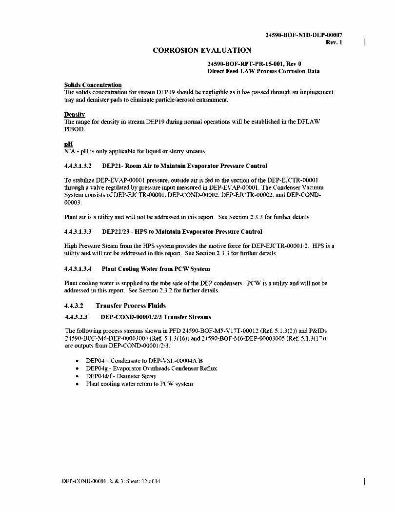
Solids Cont'entration The solids concentration for stream DEP19 should be negligible as it has passed through an impingement tray and demister pads to eliminate pa1ticle/aerosol entrainment.
Densitv The range for density in stream DEPl 9 during normal operations will be established in the DFLA W PIBOD.
I!!! N/A - pH is only applicable for liquid or slurry streams.
4.4.3.1.3.2 DEP21- Room Air to Maintain Enpo1·ator P1·eum·e Control
To stabilize DEP-EV AP-00001 pressure. outside air is fed to the suction of the DEP-EJCTR-00001 through a \·alve regulated by pressure input measured in DEP-EVAP-00001. The Condenser Vacuum System consists ofDEP-EJCTR-00001. DEP-CO:r-."'D-00002. DEP-EJCTR-00002. and DEP-COND-00003.
Plant air is a utility and will not be addressed in this report. See Section 2.3.3 for further details.
4.4.3.1.3.3 DEP22/23 - HPS to Maintain Enporato1· Pressure Conh·ol
High Pressure Steam from the HPS system pro,ides the motive force for DEP-EJCTR-00001/2. HPS is a utility and will not be addressed in this report. See Section 2.3.3 for fiuther details.
4.4.3.1.3.4 Plant Cooling Wate1· from PC\'\' S~·stem
Plant cooling water is supplied to the tube side of the DEP condensers. PCW is a utility and will not be addressed in this report. See Section 2.3.2 for forther details.
4.4.3.2 Transfer Process Fluids
4.4.3.2.3 DEP-CO:'.'i'D-00001/2/3 Transfer Sh·eams
The following process !;trea1m, shown in PFD 24590-BOF-115-Vl 7T-00012 (Ref. 5.1.3(2)) and P&IDs 24590-BOF-M6-DEP-00003004 (Ref. 5.1.3(16)) and 24590-BOF-l\16-DEP-00003005 (Ref. 5.1.3(17)) are outputs from DEP-COND-00001/2/3.
• DEP04- Condensate to DEP-VSL-00004A.B • DEP04g - Evaporator Overheads Condenser Reflux • DEP04cVf - Demister Spray • Plant cooling ,vater renllll to PCW system
DEP-COND-00001, 2, & 3: Sheet: 12 of 14
CORROSION EVALUATION
24590-BOF-NlD-DEP-00007 Rev.1
24590-BOF-RPT-PR-15-001, Rev 0 Direct Feed LAW Process Corrosion Data
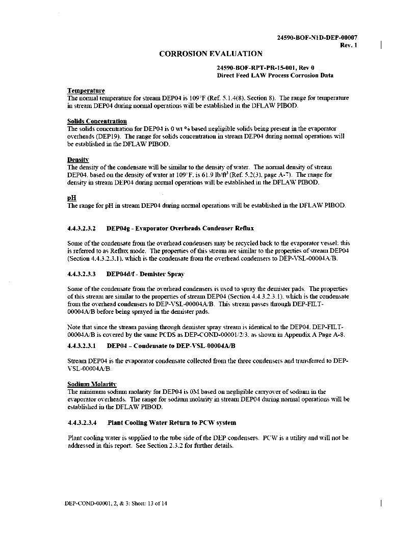
Tempera hire The nonnal temperantre for stream DEP04 is l09°F (Ref. 5.1.4(8). Section 8). The range for temperarure in stream DEP04 d1tring normal operations will be established in the DFLA W PIBOD.
Solids Concentration The solids concentration for DEP04 is O \\1 °o based negligible solids being present in the eYaporator owrheads (DEP19). The range for solids concentration in stream DEP04 dming nonnal operations will be established in the DFLAW PIBOD.
Density The density of the condensate will be similar to the density of water. The normal density of stream DEP04. based on the density of water at l09°F. is 6l.9 lbift3 (Ref. 5.2(3). page A-7). The range for density in stream DEP04 d1tring: normal operations ,vill be established in the DFLA W PIBOD.
I!!! The range for pH in stream DEP04 d1tring: normal operations will be established in the DFLA \V PIBOD.
4.4.3.2.3.2 D:EP04g - :E,·aporator Onrbeads Condenser RPflux
Some of the condensate from the oYerhead condensers may be recycled back to the eYaporator Yessel: this is referred to as Refl1Lx mode. The properties of this stream are similar to the properties of stream DEP04 (Section 4.4.3.2.3.l). which is the condensate from the oYerhead condensers to DEP-VSL-00004A/B.
4.4.3.2.3.3 D:EP04d/f - Demiste1· Spra~·
Some of the condensate from the oYerhead condensers is used to spray the demister pads. The prope1ties ohhis stream are similar to the properties of stream DEP04 (Section 4.4.3.2.3.l). which is the condensate from the oYerhead condensers to DEP-VSL-00004A/B. This sh·eam passes through DEP-FILT-00004A/B before being sprayed in the demister pads.
Note that since the stream passing through demister spray sh·eam is identical to the DEP04. DEP-FIL T-00004A/B is coYered by the same PCDS as DEP-COND-00001i2/3. as shown in Appendix A Page A-8.
4.4.3.2.3.1 D:EP04 - CondPnsatl' to D:EP-VSL-00004A/B
Stream DEP04 is the eYaporator condensate collected from the three condensers and h·a11sferred to DEPVSL-00004A/B.
Sodium Molarity The minimum sodium molatity for DEP04 is OM based on negligible canyoYer of ..,odimn in the eYaporator o\'erheads. The range for sodium molarity in stream DEP04 dming: nonnal operatiom will be established in the DFLA \V PIBOD.
4.4.3.2.3.4 Plant Cooling Watl'r RPtum to PCW s~·stem
Plant cooling: water is supplied to the tube !>ide of the DEP condensers. PCW is a utility and will not be addressed in this report. See Section 2.3.2 for fiuther detaih.
DEP-COND-00001, 2, & 3: Sheet: 13 of 14

CORROSION EVALUATION
24590-BOF-NlD-DEP-00007 Rev.1
24590-BOF-RPT-PR-15-001, Rev 0 Direct Feed LAW Process Corrosion Data
4.4.4 Process Modes
4.4.4.1 ~ormal Operations
Based on the assessment of streams frequently transfeffed in and out of DEP-EVAP-00001. the following processing modes are considered:
DEP-COND-00001 /2/3 /11/et strea111s:
• DEP19- EYaporator oYerheads to condensers • DEP21 - Room Air to maintain eYaporator pressure conb·ol • DEP22.i23 - HPS to maintain eYaporator pressure control • Plant cooling water from PCW system
Outler strea111s:
• DEP04- Condensate to DEP-VSL-00004A.iB • DEP04dif - Demister Spray • Plant cooling water renun to PCW system
4.4.4.2 Infnquent Operations
Based on the assessment of streams infrequently transfeffed in and out ofDEP-EVAP-00001. the following processing modes are not considered:
DEP-COND-00001i2i3 /11/et strea111s: No infrequent operations
0111/et sn·ea111s:
• DEP04g - Enporator OYerheads Condenser Reflux
4.4.5 Summary of Processing Conditions for the DEP Enpo.-ator Components
4.4.5.1 ~ormal Operations
The following tables s1mmutrize the nonnal process streams for the DEP Enporator components.
Table 4-7 - DEP-CO~D-00001/2/3 ~ormal Opentions Na Molarity (mol/L) I Temperatott (0 F) I UDS(wt¾)
Stream Number Low I Nonna! I Upper I Low I Nonna! I Upper I Low I Xonnal I Upper DEP19 N.'A I N.'A I X•A I TBD I 109 I 143 I 0 I 0 I 0 DEP21 (room ait·) N'A. Air is a utilitv aud 1101 addre55ed ill this reoort DEP22/23 (HPS) NIA. HPS is a utilitv and not addressed ill this reoort Plaut cooliug: water from PC\V ::-i.• A. PCW is a utility and not addressed ill this report 5.VSttelll
DEP04 0 I TBD I TBD I TBD I 109 I TBD I 0 I 0 I 0 Demister Spray 0 I TBD I TBD I TBD I 109 I TBD I 0 I 0 I 0 Plaut cooliug \\~ater rentn1 to ::,i; A. PC\V is a utility and not addressed in this report PCWsvstem
DEP-COND-00001, 2, & 3: Sheet: 14 ofl4