Math 116 & SummerMath@ Technology Center of DuPage Spring 2001 – Summer 2003.

$4.50 in the U.S.
ISSUE # 116 Spring, 2005
Ralph C. Wilson Jr. Fieldhouse, Buffalo, New York

2
From The Editor’s Desk You’ll notice on the cover that we now have a new dating format. In keeping with the quarterly publication initiative, our issues will be denoted Spring, Summer, Fall, and Winter, unless someone has a better idea. Also, there will be a timely issue coming out for each of these quarterly periods, honest. We will try for 40 pages, since Tim and I both feel that is a nice size, but I won’t hesitate to reduce that if publication time comes around. You will also notice the Buffalo Bill’s Fieldhouse on the cover. The spring and summer issues of INAV have been full of winter and spring contests, and a steady supply of plans and articles (Thank you, thank you). So in the past year we left out both the 2003 and 2004 annual Empire State Indoor Championships held in Orchard Park, NY, but include photos in this issue. This great site has a 200 by 400 foot floor and is 128 feet high. Robert Clemens is the organizer, and has said that, “This is the best kept indoor site secret going.” Since many, many of you are involved in Science Olympiad and TSA mentoring efforts, we feature several articles on SO by Ray Harlan, whose reputation and supply house need no introduction. - Carl Bakay INAV subscriptions are for a 1 year period, during which 4 issues are anticipated. USA subscriptions are mailed bulk rate, all others are air mail. Adult subscriptions: USA US$15.00/year Canada US$19.00/year All Others US$24.00/year Junior Subscriptions: subtract US$6.00 from the appropriate adult price.
Junior subscriptions are subsidized by the sale of the INAV archive CD and the donations of members. They are only available to those 18 or younger. To get a Junior rate, proof of age must be supplied with the subscription payment. Valid proof would include copies of high school or lower ID card, government issued permit, license, or ID with birthdate, Flying organization ID card showing non-adult status, or anything you feel proves your eligibility.
Send all dues to Tim Goldstein (INAV subscription editor) 13096 W. Cross Dr. Littleton, CO 80127 [email protected] Carl Bakay (editor) 1621 Lake Salvador Dr. Harvey, LA 70058-5151 [email protected]
Contributing Editors: Steve Gardner, U.S.A., Nick Aikman, U.K. Can't get enough of Indoor News And Views? Then get the INAV Archive CD. This CD includes over 250 complete issues of INAV along with a custom viewer program that allows you to print all the issues, articles, and plans. Order your Archive CD today by sending US$45.00 plus shipping (USA US$3.00 all others US$5.00) to Tim Goldstein at the above address. Proceeds from the Archive CD go to support Junior indoor flying. Indoor News and Views is an open forum presenting ideas, opinions, model designs and techniques for the indoor community. Unless specifically stated, INAV does not offer any opinion as to the merit of published work, nor does it endorse any products or services advertised herein. Sample ad copy should be sent to Tim Goldstein at the above address for publishing details.

3
PPUUBBLLIISSHHEERRSS DDEESSKK: A few housekeeping items. First, a change in the frequency of INAV. Due to the changes in my employment situation, INAV is now having to pay the full commercial rate for printing. This has increased the costs to produce this publication by about $2000/year. The choice is either to raise the rates or to switch to a 4 times per year schedule. Because I am sure you are all tired of the rate going up, we will be switching to 4 issues/year. Next up is subscription expirations. To keep costs and workload for the volunteer staff low, we do not mail out reminders. If you look at the mailing label next to your name you will see the month and year your subscription expires. When you are mailed your final issue before your expiration, we highlight this date in yellow. This is your only notice. If you are not sure when your subscription is up, just look at your label and be sure to renew before the date printed there so you don’t miss any issues. An interesting trend in subscriptions I am noticing. Our USA subscriber base is shrinking and our non-USA subscriber list is growing. Many subscribers particularly over seas are finding the ability to subscribe or renew on the web with PayPal or a credit card to be very convenient. This seems to be driving the increase in non-USA subscribers. Now, we need to do something to start increasing our USA subscriber base. Our best idea so far is to turn to our current subscribers and ask you to please recommend INAV to anyone you know that is interested in indoor FF. There is very interesting new web forum at www.SmallFlyingArts.com Due to the efforts of Bill Carney we now have an indoor FF section on the group. While I am a happy subscriber of the Indoor list on Yahoogroups, this new site offers a great format that lets you post pictures with the text. An even bigger benefit is that there are many people using this forum that are not currently indoor fliers, but are stopping by to check us out and see what this sport is all about. I would suggest stopping by and checking it out. Tim CONDENSER TISSUE
Perfect for Science Olympiad
Huge 21.5” wide x 25 foot roll only US$15.00
On a .838” OD .022” wall clear plastic tube with end caps. • Used tube makes a great blast tube or storage container. • tissue weighs .6 gm per 100 sq inches. Shipping unlimited # of rolls USA $5.25, CAN/MEX $8.75, All Others $10.50 Tim Goldstein [email protected] 13096 W. Cross Dr Order Online at Littleton CO 80127 www.IndoorDuration.com
2003 – 2004 Science Olympiad Updated Plans for Division B & C
Step by Step Illustrated Building Guide On CD-Rom with 500+ photos
CD w/plans = $25 Full Size Plans for B or C = $8
Free shipping on all orders Don Slusarczyk
868 Eaglewood Dr. Willoughby, OH 44094
Order the CD and plan online at www.indoorfreeflight.com
VVIIOOLLEETT DDRREEAAMM MMIICCRROOFFIILLMM I am using the same, standard components every time.
The well poured microfilm has uniform colors, easy to pour, spreading well, easy to lift, it is not sticky, doesn't tighten and shrink, it is properly tough and durable. I make pouring tests from every mixture, so I sell only solutions of excellent quality.
Bottle Size Prices mailing costs Europe Other
100 ml bottle 6 € 3 € 5 € 330 ml bottle 20 € 5 € 8 € 600 ml bottle 36 € 10 € 15 €
Address: Orsovai Dezsö H-1224 Budapest IX. utca 12. Hungary Email: [email protected] Fax: (36-1) 249-9827

4
THE RETURN OF THE KING! THE 2004 F1D INDOOR WORLD CHAMPIONSHIPS. SLANIC. ROMANIA. OCTOBER 4TH TO THE 9TH. For the second time in two years, I travelled back to the saltmine, this time dubbed ‘Wing Commander’, as the GB F1D Team Manager for Bob Bailey, Ron Green and Derek Richards. Arch indoor enthusiasts Geoffrey Lefever and Clive King ably supported the squadron and Bryan Stichbury (making a heroic second tour of duty as a timekeeper) completed the party. Travel was largely uneventful. Tarom again provided excellent flights with no problems about taking model boxes onboard and the use of two hire cars from Hertz was convenient. This time we used the SkyGate hotel next to Bucharest airport at either end of the trip and this was a comfortable alternative to the cheap but dismal accommodation in the city center that we suffered last time. The only excitement en route to Slanic came just after Ploesti, when we missed a turning and spent several hours examining delightfully picturesque parts of rural Romania that seemed to have disappeared off the map! After fording a river we got back on the road and arrived in time for an afternoon’s flying before the official practice day. The hotel seemed more dilapidated, the water was still brown and the feral dogs just as plentiful, but after checking-in, unpacking the model boxes and our priceless electric kettles, biscuits and provisions for afternoon tea (alas, no cucumber sandwiches), we girded our loins and took the rickety lift into the stygian gloom of the mine. Preparations for the contest were well underway, several teams were ahead of us, and friendships were quickly made or renewed before flying began. I was particularly intrigued to find out what type of props flyers would use, VP or FP and during practice several contestants tried VP props - with a variety of results. Ron green used a simple hub, longer than normal with actuator wires placed directly into the wood. This arrangement relied on the wood itself to provide the spring. Ron had several of these with wood of various densities. Bob Bailey used a more complex arrangement with the shaft above the driver arm being a secondary spring and made of thicker (0.016/0.017”) wire. I believe that most that had some flew with May ’99 rubber, although Bob Bailey opted to use March ’02. Ron and Derek had little trouble with May ’99 this time and it may be well suited to the cool mine conditions. During final preparations before leaving, Ron was cutting from one batch of May ’99 and suddenly found it de-laminating…no doubt this sounds familiar to others! The next day, during official practice, the remaining entrants arrived and anticipation increased as everyone tried to get to grips with the unique conditions. After a brief official opening ceremony, everyone retired to the hotel to finalize cunning plans for the first two contest rounds. There was little in the way of new technical developments. Steve Brown and Jim Richmond both brought some longer models than last time – Jim had one reputed to be 36” long, although I didn’t see him use it in the contest. Apart from Jim, most of the top placing flyers used flat tailplanes and fins rather than the standard GB arrangement of tip-dihedral tails on fairly long posts. German flyers Lutz Schramm and Marian Krause had some models with curved dihedral wings and Lutz used a truly elliptical layout rather than a gentle arc. He brought 2 of these models to earlier testing sessions in the Millenium Dome and explained their complex construction to me there. The German fascination with elliptical dihedral extends all the way back to Max Hacklinger and Karl- Heinze Rieke at the first ever F1D World Championships at Cardington in 1961 and 1962. I didn’t hear of anyone suffering major damage during transit and model box construction and packing remains an art. There were several beautiful and tightly packed boxes on display – Jonas Romblad from Sweden had a particularly neat example that was as finely engineered as his torque-meter and winder. The unofficial aerobatics contest produced some splendid (if unintentional) manoeuvres, caused by high torque launches and structures that weren’t stiff enough. The unanimous winner was a Polish junior flyer who executed a perfect and spectacular loop with the tailplane spars distorting into a complete circle with almost touching tips. After this excellent contortion, the tail flipped back to normal and the model climbed away while the builder bowed to much spontaneous applause.

5
The top times were almost identical to those last time, although there was much less of a gap to second place and the top individual flyers were much closer together. I believe that people flew harder than in 2002 and recognized that in order to achieve long times, it was necessary to ceiling-scrub. There were certainly more hang-ups than in 2002 and a certain amount of luck was needed to escape this grisly fate. Jim Richmond’s longest flight seemed to me to spend about 5 minutes on the ceiling in perfect position at the intersection in the mine and there were several heroic feats of very high altitude steering - notably from Bob Bailey and Dezso Orsovai. Several others were less fortunate and in the final round, Ron Green hung on the outside of the catwalk and Derek Richards hit the wall very high up in an unsteerable position. Had either of these flights survived, GB would have been amongst the medals. At the end of the contest, the maestro Jim Richmond had taken Gold yet again for the 8th time. Lutz Schramm was second and Deszo Orsovai third. The longest flight of the meeting went to John Kagan flying a variation of his ‘Eidolon’ design. His time of 36:02 was the result of a re-fly in superb air at the close of play on the first day – his first attempt was slightly longer, but the rubber had dropped off at a late stage in descent and nobody spotted this in the gloom. Team honours went to Romania, with the USA second and Hungary eventually edging out GB for Bronze by 22 seconds. For the second time, Doug Schaefer won the junior Gold medal, although he probably failed to reach his full potential due to a brief bout of illness during the second contest day. His first two flights were both 30+ and enough to secure first place by around 7 minutes. The Silver went to the USA’s Brett Sanborn and Bronze to Aurel Simpetrean from Romania.The USA juniors also took top Team honours, a great achievement, as I believe that two of them have not been flying F1D for long. Romania took the Silver and Poland the Bronze, with both teams continuing the tradition of high-level junior competition from Eastern Europe. Surprisingly, there were 5 more senior contestants than last time (36), but one less junior (13). 10 full senior teams were present along with 4 full junior squads and this time, there was no senior representation from Switzerland or Spain, although full teams arrived from France and Italy and Sweden and Serbia & Montenegro were also represented. In the junior team contest, there were full teams again from the USA, Romania, Poland and Lithuania, but no flyers from Hungary or the Ukraine – one junior from Serbia & Montenegro balanced this. The air was certainly not consistent, although flying at the start or end of the mornings/afternoons probably gave better conditions. There were quite a lot of visitors during the contest and lift activity may have had an effect on air stability. I’m sure the addition of two ‘Portaloos’ was a great relief to many! but unfortunately, the model set-up area still resembles a cattle market and is a long way from the flying area. The processing and weighing facilities are still very unsatisfactory and placed in a position that creates a human bottleneck right at the entrance to the flying area. Surely a way can be found to rethink, expand and relocate these facilities. Policing of the number of bodies in the flying area was well controlled and the human presence mostly kept to a minimum. After several days of extremely stressful competition, Rob Romash, indoor’s leading children’s entertainer, magician, top flyer and USA Team Manager added a fine touch of humour as we queued for the final lift by staging a multiple high level release of tiny gliders. Overall, the contest was undoubtedly a great success and Marius Conu in particular deserves especial thanks. All involved with organization are to be congratulated on staging another fine Championships. The banquet was a relaxing and convivial affair and for many, thoughts will now turn to the planned European Championships in Bordeaux – a completely different site with different problems. The next World Championships have already been provisionally given to Romania and the mine. So, the show rolls on! I hope to see you all soon.
Nick Aikman. 20.10.04.
(Hey, check out Nick’s new site at http://groups.msn.com/INDOORDURATIONMODELSGB It is about the European scene, but indoor modelers worldwide are invited. – Ed.)

6
FAI World Championship Indoor F1D 2004
Slanic Prahova, Romania from October 4 to 9
Flight times are given for each of the 6 rounds in 'min.sec' form. Note that * indicates the best time recorded, + marks the second best time, together these add to give the contest time given in the right hand column
Individual results
1 James Richmond W/C 1.15 11.56 36.00* 35.19+ 33.57 32.42 71.19 2 Lutz Schramm GER 35.16* 24.48 32.20 9.28 33.50+ 10.33 69.06 3 Dezso Orsovai HUN 24.10 33.58+ 32.54 33.29 33.20 34.28* 68.26 4 John Kagan USA 32.19+ 36.02* 31.18 31.50 31.19 30.48 68.21 5 Corneliu Mangalea ROM 33.26* 32.55 31.30 32.59+ 31.27 32.23 66.25 6 Aurel Popa ROM 34.24* 1.24 32.01+ 22.17 8.13 9.12 66.25 7 Fred Tellier CAN 24.35 28.40 29.45 29.49 33.02* 30.06+ 63.08 8 Tom Sova USA 31.12* 30.10 19.33 31.06+ 30.30 30.27 62.18 9 Oleksandr Kovalyov UKR 27.06 32.20* 29.13 25.50 29.37+ 2.44 61.57 10 Bob Bailey GBR 31.07* 29.27 30.09 27.45 30.26+ 29.10 61.33 11 Jonas Romblad SWE 27.08 26.13 30.31+ 11.44 28.44 30.53* 61.24 12 Ron Green GBR 1.06 29.00 29.30 30.38* 30.28+ 4.54 61.06 13 Andras Ree HUN 29.19+ 28.47 28.45 16.43 30.37* 28.06 59.56 14 Karl Schoenfelder GER 25.16 30.55* 28.51+ 10.45 22.15 25.49 59.46 15 Steve Brown USA 29.38+ 2.26 25.02 27.21 29.51* 26.17 59.29 16 Derek Richards GBR 28.45+ 25.58 21.52 24.16 30.14* 11.30 58.59 17 Thierry Marilier FRA 30.26* 25.05 9.41 27.17 28.25+ 24.42 58.51 18 Dan Amoraritei ROM 27.42+ 10.55 24.30 8.58 6.11 31.08* 58.50 19 Oleh Korniychuk UKR 24.33 19.35 24.17 28.47+ 11.51 29.40* 58.27 20 Sergiy Mosolov UKR 20.06 20.00 22.01 28.41+ 28.30 29.12* 57.53 21 Istvan Botos HUN 24.52 22.03 21.00 22.58 28.35* 25.03+ 53.38 22 Fabio Manieri ITA 21.29 24.04 1.56 24.41+ 28.28* 24.41 53.09 23 Didier Barberis FRA 0.00 27.02* 23.11 25.58 26.03+ 23.47 53.05 24 Robert Champion FRA 25.08 21.49 24.01 24.38 26.53* 25.59+ 52.52 25 Jan Dihm POL 25.08 25.33 25.57 25.58+ 26.53* 25.23 52.51 26 Jerzy Markiewicz POL 22.43 22.49 25.32+ 22.02 27.06* 19.24 52.38 27 Slobodan Midic SCG 26.38* 24.56 23.11 22.12 16.57 25.33+ 52.11 28 Edward Ciapala POL 23.07 25.32* 0.00 22.07 23.20 23.26+ 48.58 29 Peter Olshefsky CAN 22.00 22.03+ 17.43 0.57 24.41* 7.02 46.44 30 Marian Krause GER 19.37+ 26.45* 9.13 7.25 16.46 14.13 46.22 31 Yasutaka Tanaka JPN 19.59+ 0.23 25.24* 16.52 0.23 16.28 45.23 32 Giacomo De Angelini ITA 9.52 13.44 19.30+ 21.05* 0.09 0.00 40.35 33 Vojslav Stojkovic SCG 7.03 0.06 16.03 16.25+ 7.45 21.58* 38.23 34 Raymond-Jones Colin CAN 18.40* 18.00+ 16.15 13.40 16.47 17.37 36.40 35 Hideyo Enomoto JPN 15.05 15.21+ 14.38 13.31 13.30 19.53* 35.14 36 Mario Gialanella ITA 14.00 10.03 13.02 14.24+ 13.33 19.25* 33.49
Team Results Country Abbrev Total Round-by-round places 1 Romania ROM 191.40 1 7 1 2 2 1 2 USA USA 190.08 2 3 2 1 1 2 3 Hungary HUN 182.00 4 1 5 5 4 3 4 Great Britain GBR 181.38 8 4 3 3 3 4 5 Ukraine UKR 178.17 5 6 7 6 6 5 6 Germany GER 175.14 3 2 4 4 5 6 7 France FRA 164.48 9 9 6 7 7 7 8 Poland POL 154.27 6 5 8 8 8 8

7
9 Canada CAN 146.32 7 8 9 9 9 9 10 Italy ITA 127.33 10 10 10 10 10 10 11 Serbia and Montenegro SCG 90.34 12 11 12 11 11 11 12 Japan JPN 80.37 11 13 11 12 12 12 13 Sweden SWE 61.24 13 12 13 13 13 13
FAI Junior World Championship Indoor F1D 2004
Individual results
1 Doug Schaefer USA 31.21* 30.54+ 27.34 0.00 26.53 0.10 62.15 2 Brett Sanborn USA 20.47 10.12 22.04 28.18* 27.08+ 1.16 55.26 3 Aurel Simpetrean ROM 27.14* 23.43 24.00 24.43+ 1.19 14.18 51.57 4 David Rigotti Jr USA 23.50 22.21 23.21 26.19* 23.01 24.40+ 50.59 5 Krystian Kwieciak POL 19.01 13.10 20.07 23.33+ 23.52* 13.29 47.25 6 Viorel Pop Dan ROM 20.38 20.36 21.27+ 21.08 22.15* 19.11 43.42 7 Juozapas Cybas LTU 19.42 21.08+ 16.35 16.40 21.57* 15.10 43.05 8 Vilius Steponenas LTU 19.34 16.24 21.26* 17.55 0.00 20.55+ 42.21 9 Tomasz Demidowicz POL 7.05 15.07 11.37 25.36* 16.33+ 13.42 42.09 10 Zoltan Somodi ROM 19.03 20.26* 19.16+ 18.46 12.18 13.35 39.42 11 Lukas Ivanauskas LTU 16.12 13.55 17.00 18.55+ 18.35 20.41* 39.36 12 Karol Misiarz POL 18.50+ 18.08 19.02* 17.48 15.43 16.21 37.52 13 Stefan Pavelka SCG 8.14 0.00 1.13 8.31 11.58* 11.51+ 23.49
Team Results
Country Abbrev Total Round-by-round places 1 USA USA 168.40 1 1 1 1 1 1 2 Romania ROM 135.21 2 2 2 2 2 2 3 Poland POL 127.26 4 4 4 3 3 3 4 Lithuania LTU 125.02 3 3 3 4 4 4 5 Serbia and Montenegro SCG 23.49 5 5 5 5 5 5
These pages courtesy of, and with permission of, Ian Kaynes, FAI webmaster.
L to R: Dave Rigotti, Tom Sova, Doug Schaefer, Bret Sanborn, Jim Richmond, Steve Brown, John Kagan

8
KIBBIE DOME 2004 RESULTS Hand Launched Stick Intermediate Stick Bruce Kimball 27:52 1 Mike Palrang 29:34 1 Earl Hoffman 22:16 2 Earl Hoffman 25:40 2 Michael Thompson 22:52 3 F1D Junior F1D Open Tim Chang 20:07, 18:24 - 38:31 1 Steve Brown 29:50, 30:15 - 59:65 1 Anjaney Kottapalli 17:44, 18:41 - 35:85 2 Bruce Kimball 28:37, 30:05 - 58:42 2 Cezar Banks 26:15, 27:13 - 53:28 3 Eazy "B" Penny Plane Mike Palrang 28:24 1 Michael Thompson 14:24 1 Bruce Kimball 25:48 2 Tim Chang 12:20 2 Andrew Tagliafico 23:37 3 Tem Johnson 11:41 3 Limited Penny Plane R.O.G. Stick Jerry Powell 14:08 1 Andrew Tagliafico 19:29 1 Cezar Banks 13:38 2 Ed Berray 16:22 2 Ed Berray 13:03 3 Chris Doughty 12:24 3 Bostonian Mini-Stick Emil Schutzel 5:05 1 Gary Hodson 12:52 1 Jerry Powell 4:00 2 Emil Schutzel 11:55 2 Dave Haught 1:45 3 Mike Palrang 11:52 3 1.2 Eazy "B" Hand Launched Glider Jerry Powell 19:55, 20:39 - 40:34 1 Michael Thompson 60.2, 61.4 - 121.6 1 A. Tagliafico 20:12, 19:36 - 39:48 2 Bruce Kimball 56.0, 55.4 - 111.4 2 Mike Palrang 20:01, 19:44 - 39:45 3 Ed Berray 41.6, 41.8 - 83.4 3 Catapult glider Unlimited Catapult Glider Tem Johnson 84.2, 83.8 - 168.0 1 Tem Johnson 83.1, 84.0 - 167.1 1 Bruce Kimball 74.0, 72.0 - 146.0 2 Ed Berray 71.1, 73.6 - 144.7 2 Ed Berray 69.0, 71.1 - 140.1 3 Mike Thompson 70.6, 72.0 - 142.6 3 S.O. Junior S.O. Senior Ocea Nigito 12:55 1 Chris Borland 7:25 1 Julia Patterson 4:23 2 Cezar Banks 7:17 2 Rebekah Altig 4:06 3 Andrew Tagliafico 7:15 3 S.O. Mass Launch A-6 Chris Borland 7:23 1 Gary Hodson 10:13 1 Andrew Tagliafico 6:58 2 Emil Schutzel 9:46 2 Ed Berray 5:04 3 Tem Johnson 9:19 3 Manhattan Emil Schutzel 11:48 1

9
Flying in the Buffalo Bill’s Fieldhouse, Buffalo, New York Photos by Bob Clemens, [email protected]
Don Slusarcyzk with Electric FF Flying Wing Golden Age Finalists
Farman 400 Monoplane Don Steeb’s Bostonian
Wilcox Launches his F1D Fred Tellier Winding

10
Basic Glider Physics - Wash-out
By Kurt Krempetz - 8/04 Introduction When discussing glider designs whether indoor or outdoor, Hand Launch Gliders (HLG) or Catapult Launch Gliders (CLG) the subject of wash-out is typically brought up. Washout is typically thought of as twisting, shaping/sanding or adding an up tab to the trailing edge of the tips of a wing, so wing tips at a negative angle of attack compared to the root of the wing. It is believed wash-out is desirable because its thought the tips stall first and putting the tips negative compare to the rest of the wing prevents this for happening. One can view the typically Lift Coefficient vs. Angle of Attack graph to understand why this theory is believed true. Also, it is important that both wingtips are wash-out equally otherwise a roll or aileron effect is created. Yaw makes the wash-out issues even more complicated, so to keep things simple the assumption of the wing flying level, no yaw is made. Currently there are two methods typically used in glider design to add wash-out to a wing. One is the typical way of shaping/sanding the wingtips. The other is to cut the dihedral joint skew to the centerline of the wing. Typical Wash-out Method For year’s wash-out appeared in many glider designs. Bending or sanding the wingtips at the trailing edge up typically about 1/16”, added wash-out. This was thought to improve the glide of the model along with the transition from launch velocities to glide velocities. The disadvantages of wash-out are added drag, and the possible added roll to the model. Bending tabs on any flying surface is thought to be very velocity dependent. This means the characteristics of the model will change dramatically with velocity. Since gliders go through a large range of velocities this is thought to be a concern. Also at high velocities the concern of the up tab bending or flexing is an issue. When parts of a glider flex /bend or the model is velocity dependent, the trimming of the model becomes very difficult. To quantify the wash-out using this typical washout method it was decided that the change in angle of attack is the parameter of most interest. To calculate this change in angle of attack some trigonometry was applied. The tangent function is defined as:
Tan θ = Opposite/ Adjacent
To calculate the wash-out in terms of angle of attack, set a reference line that passes thru the front point of the leading edge and trailing edge of the normal airfoil. Then set a line that passes thru the front point of the leading edge and trailing edge where the trailing edge has washed up. Calculate the angle between these two lines. Tan =height washed up (H)/wing chord at this location(Wc) Or: θ = Arctan(H/Wc)

11
The following dimensions are taken from Super Sweep plans. To get an average angle of attack the dimensions were taken at the midpoint between the dihedral joint and the end of the wing.
Up tab = 1/16” Wing Chord at wingtip locations = 2 “
Therefore the change in angle of attack is: θ =Arctan(.0625/2) or doing the math θ=1.79 0 Now this is an approximation since wings are typically tapered or some other interesting elliptical shape. The angle of attack typically decreases as you move to the tip of the wing; this is not a constant number using the typical washout method. Still an approximation is better than nothing and some numbers are needed so intelligent design choices can be made. The Dihedral Wash-out Method Recently, the last 30 years, many glider designs cut the dihedral joint (poly-dihedral designs, outer dihedral joints only) skew to the centerline of the wing. Ron Whitman’s Super Sweep model had this feature, but its unknown whether he originated this idea. After spending many hours talking to some great modelers about this subject it been concluded cutting the dihedral skew to the centerline of the wing can add wash-out or wash-in. . Some paper models best illustrate the concept.
Take two pieces of paper, which is stiff enough to hold some shape. With a pen put lines on the paper, which is parallel to the centerline of the wing/fuse. This is basically the way the air flows across the wing when the wing is flying level and there is no yaw (This assumes a 2D model with no circulation around the wingtips). With one piece, bend in dihedral with the dihedral joint parallel to the centerline of the wing, the second piece put a skew angle outward (45 degrees). Now lay these pieces of paper on a flat board and measure the height from the paper to the board at both the leading and trailing at each of the pen lines.
Since the paper is lying flat on the board these measurements are 0 for both the leading and trailing edge until you get to the dihedral joint. Then note what happens. For the one with the dihedral joint that is parallel to the centerline of the wing/fuse, the height changes as you measure to the tip but the height of the trailing edge and leading edge are equal at each pen line. The angle of attack of the wingtip has not changed compared to the rest of the wing. Now measure the one with the dihedral joint pointing outward, like the Super Sweep design. After the dihedral joint the leading edge height is smaller than the trailing edge height at a specific pen line, essentially putting the tip negative compared to the rest of the wing. From this it can be concluded the wing has been wash-out.
The advantages of adding wash-out by this method is it eliminates many of the disadvantages mentioned with adding wash-out the typical way. The disadvantage of wash-out using this method is that the whole tip is at the same angle of attack, where with the typically wash-out method the angle of attack decrease as you move out further on the tip.
Again to quantify the wash-out using this dihedral wash-out method it been decided that the change in angle of attack is the parameter of most interest. To calculate this change in angle of attack you need to apply some trigonometry.

12
Most plans do not give the angle, just the Distance off of the dihedral joint, which is parallel to the centerline of the wing (X).
Tan θ =Distance off of the dihedral joint (X)
Wing Chord(Wc)
Now, Tan φ =Y/X Where φ is equal to the dihedral angle
Substituting in for X where X= Tan θ* Wc
and solving for Y the following equations is derived: Y=Tan φ*(Tan θ * Wc)
Now to calculate the angle of attack
Tan Ψ = Y/Wc
Substitute in for Y; Y=Tan φ*(Tan θ * Wc) and Solving for Ψ
Ψ=Arctan (Tan φ*Tan θ) Again the following dimensions are taken from Super Sweep plans
X =1/16” Wing Chord (Wc)= 2.945 “ Dihedral angle = 17 degrees (1.25” high tip)
The skew angle for the dihedral cut is Tan θ =.0625/2.945 = .02122 Therefore the change in angle of attack is:

13
Ψ=Arctan (Tan 17*.02122) or Ψ=.37 0 Conclusions The issue whether a good glider design should have wash-out in a wing is still not understood or settled. What is clear is there are at least two ways to create wash-out in a wing. The two methods were described both offer some advantages and disadvantages.
Plastic Films and How to Cover With Them By Ray Harlan, Wayland, MA
Now that plastic films are permitted in the Wright Stuff events, there need no longer be the frustration over tissue coverings shrinking in dry conditions or having to cover wings in three pieces or cutting wood outlines while trying to trim excess paper. Plastic films are perfectly stable, easy to work with and can be lighter than tissue. It is very important to choose the right kind of covering because there is a wide range of choices. Some are too heavy and others are much too light and fragile. In the table below, the first three are too light. Two are no longer available, but their successor, SO film, is too fragile and has a very high dielectric constant, so it gets full of static electricity unless the humidity is above 50%. PPP film is better, but still a bit fragile for these models. The .9 and 1.4 micron films probably are the best choices; they are easy to work with and are strong, but light. The previous standard WS covering, Japanese Tissue is at least 5 times heavier than these films. The thinnest films might save you 0.2 gram over the 1.4 micron film, but are so difficult to work with that they definitely are not worth using. Besides, they are very expensive. Some heavier films can be used, but they become stiffer and harder to use. Two films that are commonly available locally, dry cleaner bags and produce bags from supermarkets, are not included in the table because they are variable in thickness, depending on the supplier. They may be perfectly usable, but need their densities measured before trying them.
Product Thickness Density Source Colors um g/m2 Y2K2 0.3 0.54 No longer available bright yellow, blue Y2K 0.5 0.7 No longer available bright red, green, blue O-S Film 0.5 0.8 Tim Goldstein bright red, green PPP Film 0.7 0.9 Roy White clear Super Ultrafilm, Polymicro
0.9 1.2 Ray Harlan, Indoor Model Supply, Micro X streaky med. red, green blue
Ultrafilm 1.4 2.2 Ray Harlan, Indoor Model Supply, Micro X, Model Research Labs, Tim Goldstein
very dull red, green; almost clear
2um Clear Mylar 2 3.1 WES-Technik, David Lewis clear .012 oz Condenser Paper ? 5.3 Ray Harlan, Indoor Model Supply translucent off-white Gampi Paper ? 6.4 to 9.4 Campbell Model Supply, specialty art stores opaque off-white .020 oz Condenser Paper ? 8.8 Indoor Model Supply translucent off-white 5um Clear Mylar 5 7.1 WES-Technik, David Lewis clear Esaki Tissue ? 11 FAI Model Supply, Campbell Model Supply,
Micro X solid colors
Saran Wrap ? 20 Grocery stores clear Attaching films is easy with a spray cement. With proper care, they can provide a lighter, more uniform adhesive for films than any brushed-on coating. Brushed-on adhesives are difficult to control and take much longer to apply. One of the best features of spray cement is that it allows repositioning of the film if a mistake is made while covering. The greatest thing about films is that you can cover the wing flat and add dihedral later.

14
The first step is to choose the right product. Many spray cements (such as 3-M's Spray-Ment) produce a cream-colored lacy pattern that is too heavy and is not uniform. Much more suitable are 3-M's Super-77 or 75, and Grumbacher- 548 with fine, transparent sprays. The Super 77 is a high-tack adhesive that now comes with an extra fan-spray nozzle ideal for indoor models. For the lightest covering, the Super 75 is best. It has a lower but more than adequate tack, and is formulated for temporary bonds. The air loads on indoor models is so low that this adhesive is essentially permanent. Grumbacher-584 sprays uniformly, has moderate tack, but is heavier than Super-75. It has an orange tint that makes it easier to see. When setting up to cover a model, it is very smart to spray the model frames outdoors. This is the safest and least messy way to do the job. The cement will stay tacky for a very long time, so rushing back to the building board isn't a priority. If you must spray indoors, do it only in a garage and be sure it is well ventilated. This means fresh-air circulation (i.e. open windows). Also, cover the floor where you will spray with lots of newspaper, at least ten feet square. To help see where you are spraying, try this: shine a flashlight horizontally across the spray zone a few inches above the floor. Turn out all other lights (or spray outdoors at night) when you spray. The aerosol droplets will reflect light from the flashlight so you can see them more easily. This is a good way to estimate how much cement you are applying, and where. A black plastic background also helps you see the droplets and can be cleaned with paint thinner. The Spray cement is applied to the convex side of the ribs (top of the wing or stabilizer) only. Use just one pass on a narrow wing, and no more than two on a wider wing (one each for the leading and trailing edges). For Super-75 and Grumbacher-548, hold the can 12 to 24 inches above the frame. For Super-77, use 24 to 36 inches. Spray about one foot per second. You will be surprised how little adhesive is required. Remember, less is lighter. Another way to get a light coating is to spray up in the air and waft the model frame through the fine droplets as the descend. Two or three passes this way will be enough. Test the stickiness with a clean finger in several places around the frame. Even if it barely clings to your skin, it is enough. Wright Stuff frames are quite stiff and let you use one of several covering techniques. First, you can lay out the film on a smooth workbench. Don’t use the dining room table because later you will cut the excess film off with a pencil soldering iron. The sprayed frame is set onto the film sticky side down. Push down on one spar, getting it to stick; then, push down on the other spar. Finally, push on the ribs. Another way to cover is to put the fram on the bench, sticky side up and have two people hold the film, one hand at each corner. Lower the film onto the frame, being careful not to stretch it tight. And still a third way is to put the film on the bench, smoothing out any big wrinkles. Build a heavy balsa frame from ¼” square at least 2” larger than the wing in both directions. It can be glued together with superglue. Spray it and the wing frame. Place the heavy frame on the film and cut off the excess with a pencil soldering iron (see below). Place the sprayed wing frame on the bench and lower the film frame over it, touching the film along the spars and tips. If the ribs have a lot of camber, the frame may need to be squeezed chordwise to loosen the film and allow it to go over the ribs. There are many ways to cover a wing. Keep it a simple as possible and avoid stretching the film which might pull on the structure, just like that nasty tissue used to do. Cutting off the excess film is easy with a pencil soldering iron (a 23 to 47 watt iron with a thin chisel tip is good). Not only is this much easier than trying to use razor blades, it seals the film edge and prevents rips that might propagate readily. Be sure the iron is hot. Some irons take several minutes to heat up. The iron can be rubbed against the balsa spars or tips. Move smoothly around the frame. Sometimes melted film builds up on the iron and then leaves a black glob on the frame. Clean the goo off the hot iron with coarse sandpaper once per frame. A technique that helps to keep the big wrinkles out, makes it easier to apply the film, and makes the models fly slower without sacrificing any performance is to roll the film into a tight ball a couple of times. This produces hundreds of tiny wrinkles and gives the film a hazy appearance. It also gives it some spring so that the covering goes on smoothly. The spring is weak enough to not pull the outlines. The same frame or four-hands covering

15
techniques described above still apply. When you pull the film out from the ball, don't stretch it so much that those tiny wrinkles begin to disappear. Stretch it just enough to remove the big wrinkles. Dihedral in wings can be added at this stage. Cut long scarf splices in the spars. Starting at the outside of a dihedral rib at the inside of a spar,cut diagonally outwards and towards the center of the wing to get an angled cut about 1/4” long (for 1/16” spars). Do this for all four joints. Prop the tips up the amount called for on the plans. Note that if you cut the way described, the film holds the tip spars in place. Carefully spread the joint a little and put some glue in the opening. Push the tip spar against the center spar and repeat for the other joints. This kind of joint is a bit ugly, but has a lot of gluing area and is very strong. Also, any glue shrinkage is mostly chordwise and won’t change the dihedral angle. After it ha dried for a couple of hours, the bottom can be sanded to clean up the uglies.The film near the dihedral ribs will loosen a little. For small dihedral angles, don’t worry about it. For large angles where there is pronounced sag, wet a very small brush in spray cement (from a spot sprayed on paper) and lightly dot the film five or six places along the dihedral rib. You may want to thin the cement with some toluene (Elmer's contact cement solvent) to make brush easier. When the dots gets tacky, gently nudge the loose film against it with a thin flat (but dull) tool, or balsa sliver, from below the wing. Be careful not to push too much film onto the cement strip or the dihedral rib will bow excessively. If this happens, pull the film apart and rework it. This technique requires some practice. But remember, loose film is not too detrimental to long flights. These covering suggestions should get you well on your way to Wright Stuff modelling without the frustrations encountered with paper and other plastic covering materials. Soon you will be devising your own special techniques to further simplify the job. Good luck! Vendors: Tim Goldstein Campbell Model Supply www.fid.biz 37742 Carson www.indoorduration.com Farmington Hills, MI 48331 Indoor Model Supply FAI Model Supply Box 2020 P O Box 366 Florence, OR 97439 Sayre, PA 18840-0366 541 902-8508 570 882-9873 www.faimodelsupply.com Micro X P O Box 1063 Model Research Labs Lorain, OH 44055 www.modelresearchlabs.com [email protected] WES-Technik Ray Harlan www.wes-technik.de 15 Happy Hollow Rd. Wayland, MA 01778 www.indoorduration.com, under links David Lewis 3435 S. Orange Ave K205 Orlando, FL 32806-8538 www.homefly.com
16
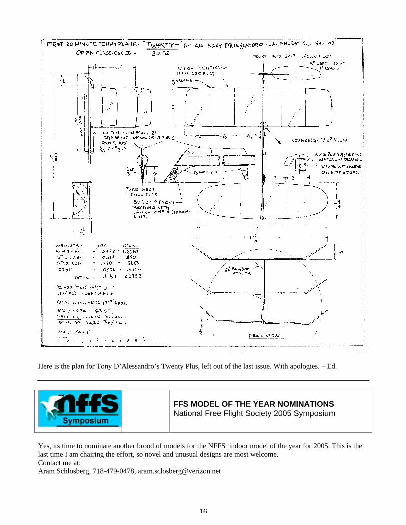
Here is the plan for Tony D’Alessandro’s Twenty Plus, left out of the last issue. With apologies. – Ed.
FFS MODEL OF THE YEAR NOMINATIONS National Free Flight Society 2005 Symposium
Yes, its time to nominate another brood of models for the NFFS indoor model of the year for 2005. This is the last time I am chairing the effort, so novel and unusual designs are most welcome. Contact me at: Aram Schlosberg, 718-479-0478, [email protected]

17
UPCOMING EVENTS TO MARK ON YOUR CALENDER FOR 2005
Jan – March Annual Hangar Rat Postal will be running again Jan. 2 to March 31st of 2005. Entry forms and rules, which are the same as last year, may be gotten from me either snail mail or email. Art Lane, [email protected], C.D. Hangar Rat Postal.
Feb 26 Unidome Indoor Ralley, Cedar Falls IA, Bob Nelson, 319-233-4771, [email protected]. March 13, Bong Eagles Annual Spring Indoor Contest, Memorial Hall, 72 Seventh St., Racine WI. A Cat
II Site. CD Joe Adams, 306 E. Kendale Dr., Oak Creek, WI 53154, 414-762-3492, [email protected]. Or Jack Boone, 262-363-3133, [email protected].
April 2, 3 Midwest Indoor Championships, hosted by the Chicago Aeronuts, University of Illinois
Armory, Champaign, IL. A 94 ft ceiling site. Bob Warmann, 630-834-9075. April 9 MMAC Annual Indoor Meet, hosted by the Minneapolis Model Aero Club, Held in the
Burnsville High School Gym, a 22’ site, south of the city. CD Gary Oakins, 651-429-3150. April 9 The Heart of America FF Association (HAFFA) Indoor Championship, Kansas City College
and Bible School, 7401 Metcalf, Overland Park, KS. Contact Emil Schutzel, 913-362-3095. April 10 Cleveland Free Flight Society annual Indoor Contest, Kent State Univ. Field House, Kent, OH. Contact Don Slusarczyk, 868 Eaglewood Dr., Willoughby, OH 44094, [email protected]. April 16 Peach State Indoor Championships, hosted by the Thermal Thumbers of Metro Atlanta. To be
held at the North Cobb High School, 3400 Old 41 Highway, Kennesaw, GA. Check out www.thermalthumbers.com David Mills, President, 404-509-4209, [email protected].
April 23,24 The Willamette Modelers Club of Albany, Oregon is hosting an Indoor Record Trials and
Symposium in the Albany High School Gym. 36’ Ceiling. CD John Lenderman, 17086 Hall Rd.,Clatskanie, OR 97016.
May 1 The 2005 Spring Indoor Fling, hosted by the Cloudbusters Model Airplane Club, Inside Swing
Golf Dome, Flint, MI. The site has a 300 x 400 ft floor and an 83 ft. ceiling. Contact George Lewis 810-329-6833, or Fred Gregg Jr. 586-264-1018.
June 1-5 United States Indoor Championships (USIC), East Tennessee State University Minidome,
Johnson City, TN. A world-class indoor football site. Abram Van Dover, CD, 757-877-2830 or Dave Thomson at 513-574-8322.
July 23-26 Kibbie Dome Annual, University of Idaho, Moscow, ID, a world class site with 144’ ceiling.
Fly 8 am to 8 pm, all classes, four days. CD Andy Tadliafico 503-452-0546.
Nov 13 Bong Eagles Annual Fall Indoor Contest, Memorial Hall, 72 Seventh St., Racine WI. Cat II site. CD Joe Adams, 306 E. Kendale Dr., Oak Creek, WI 53154, 414-762-3492, [email protected].

18
Indoor Site News and Views West Baden, IN - We have learned from Walt Van Gorder that the upper floors of the West Baden Springs hotel and atrium have been leased by Donald Trump, and are being redone into luxury suites. A gambling casino is in the works, along with a complete refurbishing of the French Lick Hotel. Tampa, FL - We also hear from Bill Carney that the Tampa Armory is changing owners, and its future as a site is in doubt. But… Rockledge, FL – Bill also tells us that a new member of the Florida Fliers, Ed Archer has gotten Rockledge Church of the Nazarene, 651 Barnes Blvd in Rockledge, Florida, 1.6 miles from US Highway 1. The church has a spacious meeting room with a clean ceiling.For those non-Floridians among you, that is on the eastern coast highway, right by Cocoa Beach and Cape Canaveral. They have already had a club contest this past January 29, 2005, and hope to have many more. As far as we know, the Prime Osborn Center in Jacksonville and the Tropicana Dome in St. Pete are still possibilities for bigger contests, but the church site is much needed for club flying on a more regular basis. Santa Ana, CA - From Steve Brown, “Nothing is going on at Santa Ana. The ownership of the base was transferred to the City of Tustin several years ago. It has been in legal limbo with much "remediation" going on to mitigate 60 years of fuel leaks, etc. Now construction is starting. Bob Randolph couldn't even get a return call.” Johnson City, TN - Got some good news and some bad for the 2005 AMA/USIC Nationals. The dates are, June 1 thru June 5. The bad news? A basketball scoreboard has been installed and will interfere with a good portion of the air space near the center of the flying space. This scoreboard will now be a permanent part of the facility. It does not make the Minidome unflyable, but it does add a different approach to launching and trimming your model. ETSU has given up football with the 2003 season. Basketball is now the big money maker in sports at the school. On the good side we have brought back some events dropped for the 2004 event. A poll was run at the 2004 Indoors asking what events the contestants would like to have on the 2005 schedule. The events most popular in the poll were brought back. A-ROG, Ornithopter and Ministick Mass Launch. We also dropped two events: AMA Rubber scale and RC Electric Duration. We will also need a new Contest Director for 2005. I feel that four years is enough and I would like to get some indoor flying in. - Abram Van Dover Buffalo, NY – Bob Clemens tells us that if the scoreboard situation causes loss of attendance at USIC, the Buffalo Bills Fieldhouse management is receptive to hosting the Championships in New York.
Rockledge Church of the Nazarene site. The new USIC scoreboard, 35’ lowered, 55 raised
19
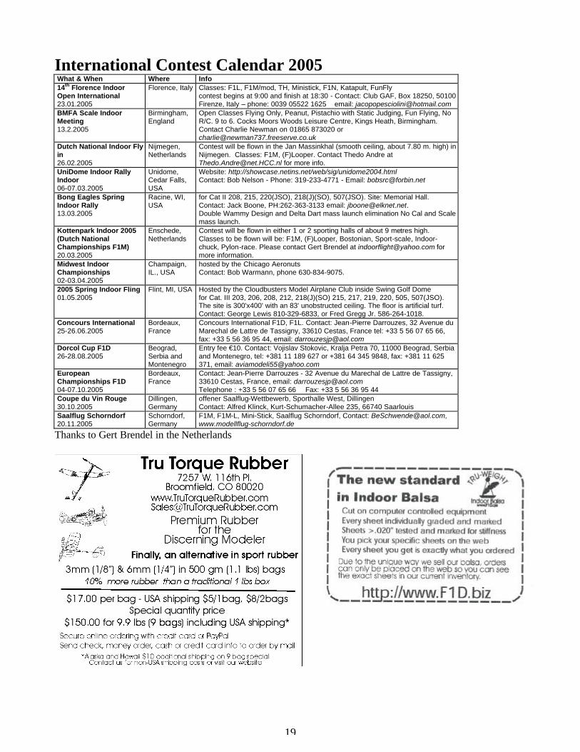
International Contest Calendar 2005 What & When Where Info 14th Florence Indoor Open International 23.01.2005
Florence, Italy Classes: F1L, F1M/mod, TH, Ministick, F1N, Katapult, FunFly contest begins at 9:00 and finish at 18:30 - Contact: Club GAF, Box 18250, 50100 Firenze, Italy – phone: 0039 05522 1625 email: [email protected]
BMFA Scale Indoor Meeting 13.2.2005
Birmingham, England
Open Classes Flying Only, Peanut, Pistachio with Static Judging, Fun Flying, No R/C. 9 to 6. Cocks Moors Woods Leisure Centre, Kings Heath, Birmingham. Contact Charlie Newman on 01865 873020 or [email protected]
Dutch National Indoor Fly in 26.02.2005
Nijmegen, Netherlands
Contest will be flown in the Jan Massinkhal (smooth ceiling, about 7.80 m. high) in Nijmegen. Classes: F1M, (F)Looper. Contact Thedo Andre at [email protected] for more info.
UniDome Indoor Rally Indoor 06-07.03.2005
Unidome, Cedar Falls, USA
Website: http://showcase.netins.net/web/sig/unidome2004.html Contact: Bob Nelson - Phone: 319-233-4771 - Email: [email protected]
Bong Eagles Spring Indoor Rally 13.03.2005
Racine, WI, USA
for Cat II 208, 215, 220(JSO), 218(J)(SO), 507(JSO). Site: Memorial Hall. Contact: Jack Boone, PH:262-363-3133 email: [email protected]. Double Wammy Design and Delta Dart mass launch elimination No Cal and Scale mass launch.
Kottenpark Indoor 2005 (Dutch National Championships F1M) 20.03.2005
Enschede, Netherlands
Contest will be flown in either 1 or 2 sporting halls of about 9 metres high. Classes to be flown will be: F1M, (F)Looper, Bostonian, Sport-scale, Indoor-chuck, Pylon-race. Please contact Gert Brendel at [email protected] for more information.
Midwest Indoor Championships 02-03.04.2005
Champaign, IL., USA
hosted by the Chicago Aeronuts Contact: Bob Warmann, phone 630-834-9075.
2005 Spring Indoor Fling 01.05.2005
Flint, MI, USA
Hosted by the Cloudbusters Model Airplane Club inside Swing Golf Dome for Cat. III 203, 206, 208, 212, 218(J)(SO) 215, 217, 219, 220, 505, 507(JSO). The site is 300'x400' with an 83' unobstructed ceiling. The floor is artificial turf. Contact: George Lewis 810-329-6833, or Fred Gregg Jr. 586-264-1018.
Concours International 25-26.06.2005
Bordeaux, France
Concours International F1D, F1L. Contact: Jean-Pierre Darrouzes, 32 Avenue du Marechal de Lattre de Tassigny, 33610 Cestas, France tel: +33 5 56 07 65 66, fax: +33 5 56 36 95 44, email: [email protected]
Dorcol Cup F1D 26-28.08.2005
Beograd, Serbia and Montenegro
Entry fee €10. Contact: Vojislav Stokovic, Kralja Petra 70, 11000 Beograd, Serbia and Montenegro, tel: +381 11 189 627 or +381 64 345 9848, fax: +381 11 625 371, email: [email protected]
European Championships F1D 04-07.10.2005
Bordeaux, France
Contact: Jean-Pierre Darrouzes - 32 Avenue du Marechal de Lattre de Tassigny, 33610 Cestas, France, email: [email protected] Telephone : +33 5 56 07 65 66 Fax: +33 5 56 36 95 44
Coupe du Vin Rouge 30.10.2005
Dillingen, Germany
offener Saalflug-Wettbewerb, Sporthalle West, Dillingen Contact: Alfred Klinck, Kurt-Schumacher-Allee 235, 66740 Saarlouis
Saalflug Schorndorf 20.11.2005
Schorndorf, Germany
F1M, F1M-L, Mini-Stick, Saalflug Schorndorf, Contact: [email protected], www.modellflug-schorndorf.de
Thanks to Gert Brendel in the Netherlands

20
John Diebolt Wins Oppegard Trophy for 2004 To Michael Smith, Curator AMA Museum, Muncie, IN Hi Michael: John O'Leary here. I'm the former editor of the Minneapolis Model Aero Club newsletter and was one of two club members (Gary Oakins, the other) who initiated the effort to have an AMA perpetual trophy, honoring Bob Oppegard's contribution,in the museum collection. The Minneapolis MAC is very pleased that this event took place during the AMA Outdoor Free Flight Nats with Abram Van Dover, CD, Gary Oakins and yourself attending.The trophy acknowledges the high time winner of the Pennyplane event at each AMA Indoor Nats. According to the Indoor News and Views, the 2004 winner was John Diebolt, AMA #5286, with a time of 17:34. Could you follow through and send a congratulatory letter to John and have the brass plate inscribed with his name, date and time. If you could get back to me with John Diebolt's address, phone number and email address, I'd appreciate the opportunity to send him a congrats note on behalf of the club. John O'Leary, AMA #86735 Photos show Abram Van Dover, CD of the 2004 Indoor Nationals, bottom, and Michael Smith, Curator, AMA Museum, top.

21
“F1D 2004 – 4 “ First place 2004 Kibbiedome Winner by Steve Brown, San Dimas, CA

22
How to Make a Flight Log By Ray Harlan, Wayland, MA
Even when first trimming your model to fly, it is useful to create a flight log. It will help you sort out which variables are influencing the model’s performance and by how much. Keeping good notes will help you fly the model consistently after it is trimmed. Rubber can be very fickle and seem not to behave the same way on consecutive flights. However, usually it is some difference in the way it is wound or torque levels that is the culprit. A torque meter is one of the most useful tools to get consistent flights. You can make one (ask me for a copy of the article Build a Simple Torque Meter) or purchase it from one of the mail-order companies (www.indoorduration.com and links on that site). Let’s take a look at the nine parameters in the table below. Although you only need six to have a qualified flight log, there are more parameters that should be recorded if you want to learn how to get the most from your model. Motor length always is measured when the motor is new and has never been wound. After a motor is wound the first time, it has some permanent stretch that will increase slightly as it is wound more times. Since the motor weighs 2 grams, or something close to that, and the density of rubber is nearly constant, the only parameter we need to define whether the motor is skinny or fat is the length. If you get your best times on a 14” motor, you will know that a 13” motor will run out of turns too soon or get the model too high and that a 15” motor will not get your model high enough to fly a long time and will come down with a lot of turns left. Being able to adjust the width of a motor, so the length can be changed and the weight held constant, requires the use of a rubber stripper to cut custom widths. There may be a model airplane enthusiast in your area who has one. When you wind a motor, you should get it close to breaking in order to make it do the most work for you. That is not to say that you launch the model with it fully wound. Rubber exhibits a hysteresis effect; you don’t get out what you put in! By winding it all the way up, the unwinding torque curve will be flatter and will have a higher average torque than if the motor is only wound to the launch torque. By recording the max torque and turns, you will know what levels did not break the motor, so you may be able to repeat them for the next windup. After you have gotten the model to fly well, it is worthwhile to wind some motors to breaking so that you know the limits. Rubber is capricious; it may break at surprisingly low torque levels. Always check the motor for little tears in it. (Especially around the knot. – Ed) If you see any fraying, discard it. The next two parameters, launch turns and torque, go hand-in-hand to define the energy in the motor at the start of a flight. For a particular motor, they are the variables that control how high the model will climb. Since we fly mostly in low ceilings that have nasty girders, they are critical to learn in order to keep the model safe. The maximum torque that a motor can be wound to is 5 or 6 times higher than the average torque. This means that the rubber is very nonlinear in its torque characteristics. This isn’t a terrible thing for us, however. It is easy to see how raising or lowering these two parameters affects peak height. You can think of it this way: at some torque, the model will just fly steady and level. If the torque is increased, it will climb until the motor has unwound to the point of level flight torque. Further unwinding will lower the torque and the model will begin to descend. Finding the right launch torque should be done in steps. If the model climbs halfway up with 1200 turns, add only 100 turns to the next flight. Notice that the torque goes up much more than the 8% you increased the turns. This time, the model might go three quarters of the way up. Succeeding flights should have turns increased by smaller increments until the model just touches the girders once or twice (or maybe not at all if they catch models easily). It is important to know how to wind a motor to get the most out of it. To get the most turns, it needs to be lubricated and stretched. Use a lube like ArmorAll or Formula 2001, found in auto parts stores. After some of the liquid has evaporated, they get nice and greasy to keep the rubber from chafing on itself. Stretch the motor about 6 feet and put half of the turns in at that distance. Then continue winding and moving closer to the other

23
end of the motor until it is about 12” long when fully wound. Of course you don’t know what max turns are, so it is clear you need to wind the motor several times and ultimately break it so you can find out how much it takes. Once you have gotten the model to reach the ceiling, it is time to fine tune the motor used. Every time it lands, put the winder back on the rear of the motor and count how many turns are left. This is a good clue in choosing the right motor. If the rubber has only a few turns, or it ran out of turns in the air, the motor is too short and you need more turns. If it comes down from the ceiling with 700 or more turns, the motor is too long. Ideally, the average torque should be near that needed for level flight. Finding average torque is complex and not really needed. Instead, just experiment with different length motors until you find the one that gets the best time. In a low ceiling (20 – 30 ft.), 250 to 500 turns at landing may be about right. As a motor is used for more flights, it will take some more turns to get to the max torque. Most of this energy is seen at the end of rundown and is not useful. The important thing is to wind to the same peak torque each time. After each flight, inspect the rubber for nicks or fraying. Discard any that are damaged. You can measure the height of your flying site with a balloon on a string. Let the balloon touch the girders and use a tape measure to find the length of the string and balloon after it is pulled down parallel to the floor. Proportioning this height (1/2, 3/4, 7/8 etc.) gets you the peak height entry in the log. Measure off 20 feet on the floor and mark both ends with tape. Start with a heel at the first mark and walk naturally to the second mark, counting steps as you go. Divide 20 by the number of steps to get your step length. When your model is flying, stand under it as it flies by and start walking to the other side of the circle in which it is flying. Count the steps and multiply by the length of your step to get the circle diameter. Models should fly in small circles (10 -15 ft) in small sites and larger circles (20 - 30 ft) in larger sites. If the circle is small and the model is banking a lot, it needs to be retrimmed, perhaps adding left wing washin (twist trailing edge down), removing some left rudder and left thrust. In a site with a peaked roof, a small circle lets the model climb higher and if it does hit a girder and the circle moves, it has less chance of getting into trouble. It should be clear by now that the parameters listed in the flight log are very useful for improving flights as you build up experience with your model. There are lots more things that could be recorded, but these are the most important ones. Lots of practice will make you a better flier, able to find the best settings in a new flying site at a regional or state meet much faster than someone who just finished a model the night before. Flight 1 Flight 2 Flight 3 Flight 4 Flight 5 Motor length (new) Max turns Max torque Launch turns Launch torque Turns at landing Flight time Peak height Circle diameter (Ray’s original article had four of these tables on one page. We only show one to save space. –Ed.)
24
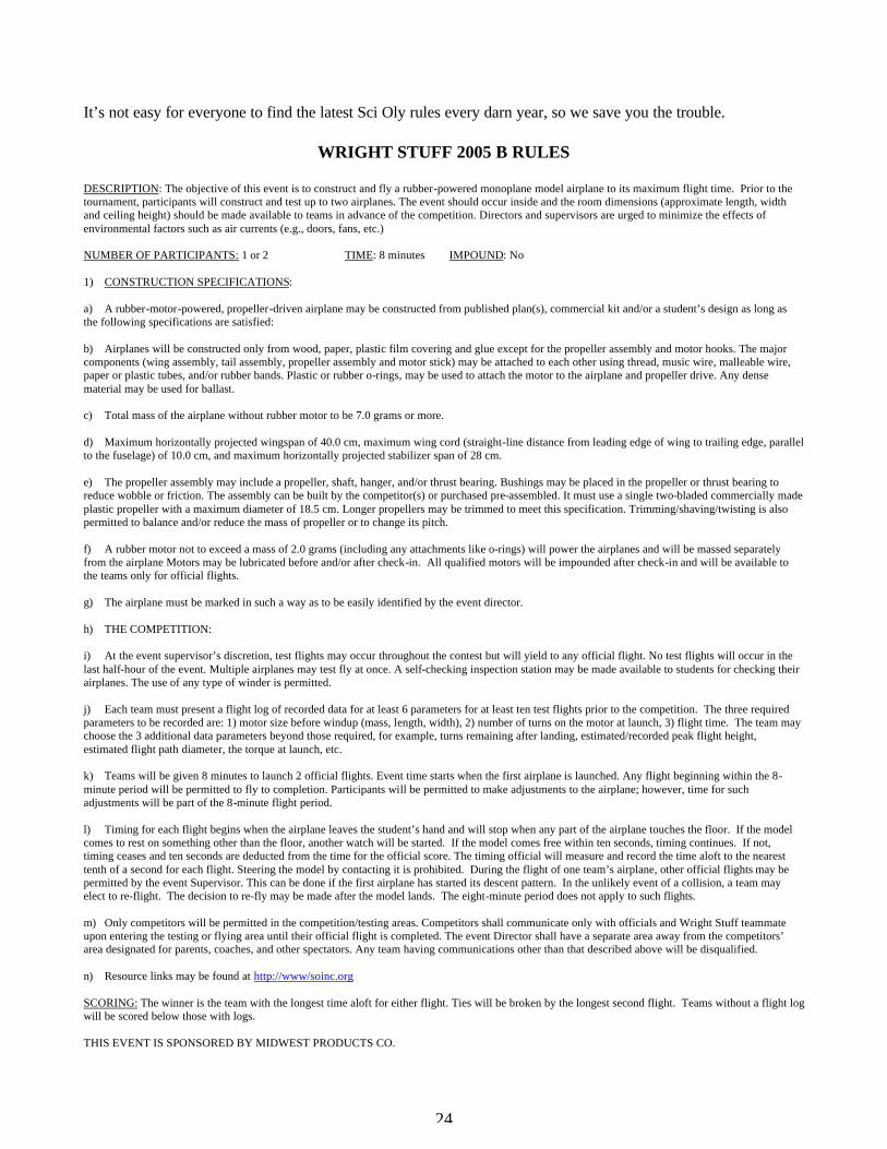
It’s not easy for everyone to find the latest Sci Oly rules every darn year, so we save you the trouble.
WRIGHT STUFF 2005 B RULES
DESCRIPTION: The objective of this event is to construct and fly a rubber-powered monoplane model airplane to its maximum flight time. Prior to the tournament, participants will construct and test up to two airplanes. The event should occur inside and the room dimensions (approximate length, width and ceiling height) should be made available to teams in advance of the competition. Directors and supervisors are urged to minimize the effects of environmental factors such as air currents (e.g., doors, fans, etc.) NUMBER OF PARTICIPANTS: 1 or 2 TIME: 8 minutes IMPOUND: No 1) CONSTRUCTION SPECIFICATIONS: a) A rubber-motor-powered, propeller-driven airplane may be constructed from published plan(s), commercial kit and/or a student’s design as long as the following specifications are satisfied: b) Airplanes will be constructed only from wood, paper, plastic film covering and glue except for the propeller assembly and motor hooks. The major components (wing assembly, tail assembly, propeller assembly and motor stick) may be attached to each other using thread, music wire, malleable wire, paper or plastic tubes, and/or rubber bands. Plastic or rubber o-rings, may be used to attach the motor to the airplane and propeller drive. Any dense material may be used for ballast. c) Total mass of the airplane without rubber motor to be 7.0 grams or more. d) Maximum horizontally projected wingspan of 40.0 cm, maximum wing cord (straight-line distance from leading edge of wing to trailing edge, parallel to the fuselage) of 10.0 cm, and maximum horizontally projected stabilizer span of 28 cm. e) The propeller assembly may include a propeller, shaft, hanger, and/or thrust bearing. Bushings may be placed in the propeller or thrust bearing to reduce wobble or friction. The assembly can be built by the competitor(s) or purchased pre-assembled. It must use a single two-bladed commercially made plastic propeller with a maximum diameter of 18.5 cm. Longer propellers may be trimmed to meet this specification. Trimming/shaving/twisting is also permitted to balance and/or reduce the mass of propeller or to change its pitch. f) A rubber motor not to exceed a mass of 2.0 grams (including any attachments like o-rings) will power the airplanes and will be massed separately from the airplane Motors may be lubricated before and/or after check-in. All qualified motors will be impounded after check-in and will be available to the teams only for official flights. g) The airplane must be marked in such a way as to be easily identified by the event director. h) THE COMPETITION: i) At the event supervisor’s discretion, test flights may occur throughout the contest but will yield to any official flight. No test flights will occur in the last half-hour of the event. Multiple airplanes may test fly at once. A self-checking inspection station may be made available to students for checking their airplanes. The use of any type of winder is permitted. j) Each team must present a flight log of recorded data for at least 6 parameters for at least ten test flights prior to the competition. The three required parameters to be recorded are: 1) motor size before windup (mass, length, width), 2) number of turns on the motor at launch, 3) flight time. The team may choose the 3 additional data parameters beyond those required, for example, turns remaining after landing, estimated/recorded peak flight height, estimated flight path diameter, the torque at launch, etc. k) Teams will be given 8 minutes to launch 2 official flights. Event time starts when the first airplane is launched. Any flight beginning within the 8-minute period will be permitted to fly to completion. Participants will be permitted to make adjustments to the airplane; however, time for such adjustments will be part of the 8-minute flight period. l) Timing for each flight begins when the airplane leaves the student’s hand and will stop when any part of the airplane touches the floor. If the model comes to rest on something other than the floor, another watch will be started. If the model comes free within ten seconds, timing continues. If not, timing ceases and ten seconds are deducted from the time for the official score. The timing official will measure and record the time aloft to the nearest tenth of a second for each flight. Steering the model by contacting it is prohibited. During the flight of one team’s airplane, other official flights may be permitted by the event Supervisor. This can be done if the first airplane has started its descent pattern. In the unlikely event of a collision, a team may elect to re-flight. The decision to re-fly may be made after the model lands. The eight-minute period does not apply to such flights. m) Only competitors will be permitted in the competition/testing areas. Competitors shall communicate only with officials and Wright Stuff teammate upon entering the testing or flying area until their official flight is completed. The event Director shall have a separate area away from the competitors’ area designated for parents, coaches, and other spectators. Any team having communications other than that described above will be disqualified. n) Resource links may be found at http://www/soinc.org SCORING: The winner is the team with the longest time aloft for either flight. Ties will be broken by the longest second flight. Teams without a flight log will be scored below those with logs. THIS EVENT IS SPONSORED BY MIDWEST PRODUCTS CO.

25
WRIGHT STUFF 2005 C RULES DESCRIPTION: The objective of this event is to construct and fly a rubber-powered model airplane to its maximum flight time. Prior to the tournament, participants will construct and test up to two airplanes. Biplanes are permitted. The event should occur inside and the room dimensions (approximate length, width and ceiling height) should be made available to teams in advance of the competition. Directors and supervisors are urged to minimize the effects of environmental factors such as air currents (e.g., doors, fans, etc.). NUMBER OF PARTICIPANTS: UP TO 2 TIME: 8 minutes IMPOUND: No 1) CONSTRUCTION SPECIFICATIONS:
a) A rubber-motor-powered, propeller-driven airplane may be constructed from published plan(s), commercial kit and/or a student’s design as long as the following specifications are satisfied:
b) Airplanes will be constructed only from wood, paper, plastic film covering and glue except for the propeller assembly, ribbon assembly and
motor hooks. The major components (wing assembly, tail assembly, propeller assembly and motor stick) may be attached to each other using thread, music wire, malleable wire, paper or plastic tubes, and/or rubber bands. Plastic or rubber o-rings may be used to attach the motor to the airplane and propeller drive. Any dense material may be used for ballast.
c) Total mass of the airplane throughout the flight, excluding the rubber motor, must be 8.0 grams or more.
d) Maximum horizontally projected wing span of 48.0 cm, maximum wing chord (straight line distance from leading edge of wing to trailing
edge, parallel to the fuselage) of 12.0 cm, and maximum horizontally projected stabilizer span of 35.0 cm
e) The propeller assembly may include a propeller, a shaft, a hanger, and/or a thrust bearing. Bushings may be placed in the propeller or thrust bearing to reduce wobble or friction. The assembly can be built by the competitor(s) or purchased pre-assembled. It must use a single two-bladed commercially made plastic propeller with a maximum diameter of 24.0 cm. Longer propellers may be trimmed to meet this specification. Trimming/shaving/twisting is also permitted to balance and/or reduce the mass of propeller or to change its pitch.
f) A rubber motor not to exceed a mass of 2.0 grams (including any attachments like o-rings) will power the airplanes and will be massed
separately from the airplane. Motors may be lubricated before and/or after check-in. All qualified motors will be impounded after check-in and will be available to the teams only for official flights.
g) The airplane must be marked in such a way as to be easily identified by the event supervisor.
2) THE COMPETITION:
a) At the event supervisor’s discretion, test flights may occur throughout the contest but will yield to any official flight. No test flights will occur in the last half-hour of the event. Multiple airplanes may test fly at once. A self-checking inspection station may be made available to students for checking their airplanes. The use of any type of winder is permitted.
b) Each team must present a flight log of recorded data for at least 6 parameters for at least ten test flights prior to the competition. The three
required parameters to be recorded are: 1) motor size before windup (mass, length, width), 2) number of turns on the motor at launch, 3) flight time. The team may choose the 3 additional data parameters beyond those required, for example, turns remaining after landing, estimated/recorded peak flight height, estimated flight path diameter, the torque at launch, etc.
c) Teams will be given 8 minutes to launch 2 official flights. Event time starts when the first airplane is launched. Any flight beginning within the
8-minute period will be permitted to fly to completion. Participants will be permitted to make adjustments to the airplane; however, time for such adjustments will be part of the 8 minute flight period.
d) Timing for each flight starts when the airplane leaves the student’s hand and will stop when any part of the airplane touches the floor. If the
model comes to rest on something other than the floor, another watch will be started. If the model comes free within ten seconds, timing continues. If not, timing ceases and ten seconds are deducted from the time for the official score. The timing official will measure and record the time aloft to the nearest tenth of a second for each flight. Steering the model by contacting it is prohibited. During the flight of one team’s airplane, other official flights may be permitted by the event Supervisor. This can be done if the first airplane has started its descent. In the unlikely event of a collision, a team may elect a re-flight. The decision to re-fly may be made after the model lands. The eight-minute period does not apply to such flight.
e) Only competitors will be allowed in the testing/flying areas. Competitors shall communicate only with officials and their Wright Stuff
teammate upon entering the testing/flying areas until after their official flights have been completed. The event director shall have a separate area away from the competitors’ area designated for coaches, parents, and other spectators. Any team having any type of communication other than that described above shall be disqualified.
f) Bonus: At the State level, a 15 seconds bonus may be earned by having the airplane release a ribbon during the flight anytime after the first 15
seconds and before the airplane lands. At the National level, a 20 second bonus will be awarded if the ribbon is released from 30-45 seconds into the flight. The ribbon size must be at least 1.0 cm wide X 10.0 cm long and readily seen. The ribbon and any parts to be released will not be included in the mass of the airplane nor in the mass of the motor.
g) Resource links may be found at http://www/soinc.org
SCORING: The winner is the team with the longest time aloft for either flight. Ties will be broken by the longest time of the other flight. Teams without a flight log will be scored below those with logs. THIS EVENT IS SPONSORED BY MIDWEST PRODUCTS CO.

26
Indoor Postal Contest Results Form
Club Name___________________
2005 International Postal Contest %Andrew Tagliafico 10039 SW Quail Post Rd. Portland, OR 97219 USA
Date of Contest_____/_____/_____ Site Name____________________
Ceiling Height_____________Feet Circle One: Ministick A-6
Contestant Name
Address Time in Seconds
Timer Initials

27
2005 INTERNATIONAL INDOOR POSTAL CONTEST
For Ministick and A-6 Events Andrew Tagliafico and Bob Stalick are pleased to announce our sponsorship of the 2005 International Indoor Postal Contest
again. This year we are sponsoring two events: Ministick and A6. The competition will begin on January 1, 2005 and conclude on April 30, 2005. As in the past, contestants may fly as many times as they wish in as many sites as they wish during this 4 month period. Only the highest score will be counted in each event. All scores are to be mailed to Andrew Tagliafico at the address below, and all scores must be received no later than May 15, 2004. Scores received after May 15 will be disregarded.
Scores will be published twice during the competition and sent to all who have registered scores. The first publication is expected to be around March 1, 2005. The second and final publication of scores will be after all flights have been registered and is expected to be around June 1, 2005. All participants will receive a final report. Trophies will be awarded to third place in each event.
All scores must be posted on the official score sheet, which is attached. Please use only this form or photocopies of it and send only to Andrew Tagliafico. **Note: This is the last year that we will be sponsoring this International Indoor Postal Contest. If any individual or club wishes to assume sponsorship for 2006, please contact Andrew Tagliafico ASAP. ** Ministick The contest is open to indoor models that comply with the AMA Ministick rules. All contest flights are to be timed by someone other than the flier. The best single flight time wins., after the flight time has been corrected for different ceiling heights. Ceiling height to be measured as per FAI rules, but with a five meter diameter circle. The corrections factor is 627 divided by (167+46x the square root of the ceiling height in feet). The time in seconds will be multiplied by this number to give the corrected time. Mini-Stick Model Rules 1. The Ministick model shall be a monoplane covered with any commercially available material sold in sheet from. Microfilm is not allowed. 2. The maximum projected wingspan shall be seven (7") inches. 3. The maximum wing chord shall be two and one-half (2 1 / 2") inches. 4. The maximum length from front of nose bearing to front of rear motor hook shall be five (5") inches. 5. The maximum length from front of nose bearing to rearmost part of model shall b e ten (10") inches. 6. The projected area of the stabilizer shall not exceed 50 percent of the projected area of the wing. 7. The maximum diameter of the propeller shall be seven (7") inches. The propeller shall be constructed of wood. Wire shafts are permitted. Hubs that allow blade replacement and/or manual pitch adjustment are allowed. Mechanisms that cause variable pitch and/ or variable diameter of propellers while in flight shall not be allowed (Natural flexing and flaring of wooden blades is allowed). 8. The minimum overall weight of the model (without motor) shall be 0.015 ounce. 9. Construction is to be primarily wood, with adhesives used only for joining Tissue and/or thread is permitted for wrapping bearings, hooks and for making sockets, if desired. Boron, carbon fiber, Kevlar and fine wire bracing are not permitted. 10. Mechanisms that restrict the torque available to the propeller are not allowed. Send Results to: Andrew Tagliafico
10039 SW Quail Post Road Portland, OR 97219 USA
A-6 The contest is open to indoor models that comply with the A-6 rules. All contest flights to be timed by someone other than the flier. Best single flight time wins after the flight time has been corrected for the 70 foot factor. Ceiling height will be determined by the AMA/FAI measurement method. Flight times will be. normalized against times from the highest site entered according to the following formula: The normalized flight time = 2/3 (highest ceiling height - local ceiling height) + (local time). *Highest ceiling height will be
established at 70 feet until an entry from a higher site is received. The official normalized times will not be available until the competition is completed.
A-6-Model Rules 1. 30 sq. in. max wing area 2. 1/32" max prop shaft diameter 3. A 6" max prop diameter. The blades are to be flat, no camber. Blades may be made from 1/32" thick (1 mm) balsa or unlightened plastic but not foam. 4. 6" max motor stick length as measured from the prop thrust bearing to the rear hook Tail boom length is unlimited. 5. All strip wood construction is to be a minimum of 1 / 16" x 1 / 16" (1.5mm x 1.5mm where only metric sizes are available). Strip wood may not be modified to any shape other than a square. 6. All sheet wood construction, prop blades, wing and stab ribs are to be a minimum of 1/32" (1 mm) thick. Prop ade edges may not be rounded. 7. All wing and stab ribs will be 1/32" x 1 / 16" (1.5mm x 1.0 mm) minimum cross section. 8. Covering materials are limited to: Japanese tissue, Gampi paper or condenser paper. 9. Only wood, wire, adhesives and allowed covering materials can be used for construction with the exception of the prop shaft support and bearing which maybe wire, aluminum or plastic. No special indoor material maybe used. 10. Rubber power only. 11. The use of metric size wood is restricted to those who normally cannot get other size wood. 12. The model must weight a minimum of 1.2 grams.

28
Editors are often pack rats when it comes to rosters and membership lists, and yours truly is one of the worst. I am always surprised at how few of you on the INAV rolls belong to the National Free Flight Society, and are getting Walt Rozelle’s great 32 page Digest every month. We were selling NFFS Directories at Johnson City, you see, and their 2004 roster is a window into the larger US free flight community. Walter showed up at the Tampa armory this spring and got the indoor bug, and our own John Kagan and Jim Buxton have been sending indoor photos and articles to the Digest on a regular basis. For example, the July/August 2004 issue devoted 9 ½ pages plus the cover to USIC. The same issue had the following by Jim Buxton, and since too many of us (myself included) have only a vague idea of who our leadership is, or what they are up to on our behalf, we reprint it here. NFFS Indoor Committee Sets Goals, Seeks Community Input By Jim Buxton, Hilliard, Ohio I want to take this opportunity to introduce myself to NFFS members. It is an honor to serve as chairman of the newly established Indoor Committee, which is part of the NFFS Competitions Committee. Goal of this committee is to promote indoor free flight, and funnel our thoughts and projections to the NFFS Board of Directors. Members of the Indoor Committee are:
Jim Buxton (Hilliard, OH); John Kagan (Strongsville, OH); Larry Coslick (St. Louis, MO); Tony Italiano (Brookfield, WI); Jim Lewis (Macon, GA); Gary Baughman (Marietta, GA); and Don Slusarczyk (Willoughby, OH). I am thankful to have such a strong and dedicated group of people surrounding me. We are all committed to improving the current situations the indoor community is facing.
The committee’s first step was to hold a meeting on the eve of the US Indoor Championships. The meeting was attended by members of the committee, Rex Hinson (president of NFFS), and anyone who happened to pass by. A few of the items that were covered during this meeting were:
(1) Keys to insuring the future success of USIC. Look for an article in an upcoming Digest by a guy who should know, Tony Italiano.
(2) An indoor U.S. high-point program for the indoor community. The idea stemmed from the great success of the America’s Cup and National Cup outdoor programs. The idea is to increase participation at local and regional levels by establishing a national point system. Jim Lewis will be helping to collect all of the ideas and get a plan implemented by the 2005 contest year. Send your thoughts and suggestions to Jim Lewis, 76 Jennings LN., Macon, GA, 31210.
(3) More publicity for the indoor community. I will be soliciting more indoor material to appear in Digest. Attention to indoor matters on the NFFS Web site will be expanding as well. One aspect of this will include a complete indoor contest listing*. Please contact me regarding any indoor contests that are planned, and I will be compiling the information to be placed on the site. Our goal is to have dates, contact info, site descriptions and contest flyers for every indoor contest of the season, accessible on the Web. Contact Jim Buxton, 3956 Wallington Dr., Hilliard, OH, 43026.
(4) John Kagan will be assembling a thorough and accurate list of all known active indoor venues. This is a formidable task, so please help John by informing him of any indoor activity in your area. He wants to know when, where, how often, and what the building looks like. John will also be working on researching new sites for our use. Contact John at 20100 Killian’s Grove, Strongsville, OH 44149.
This is just the beginning. We have much work to do and need the help of the entire indoor community. The members of this committee are here to collect the ideas and help bring them to life. Please contact any committee member and share your ideas. The committee needs input from the membership to improve publicity and participation, the biggest problems facing indoor today. We need the help of the entire membership, and new members to preserve indoor flying for future generations.
*Go to http://freeflight.org for the NFFS site, then click on Competitions at the top, then Indoor Contest
Calender, then after browsing that, click on the line that says, "Here is an Extensive Listing of Upcoming Events by Location by Jim Buxton." The last will be almost exactly what we run in each issue of Indoor News and Views. – Ed.
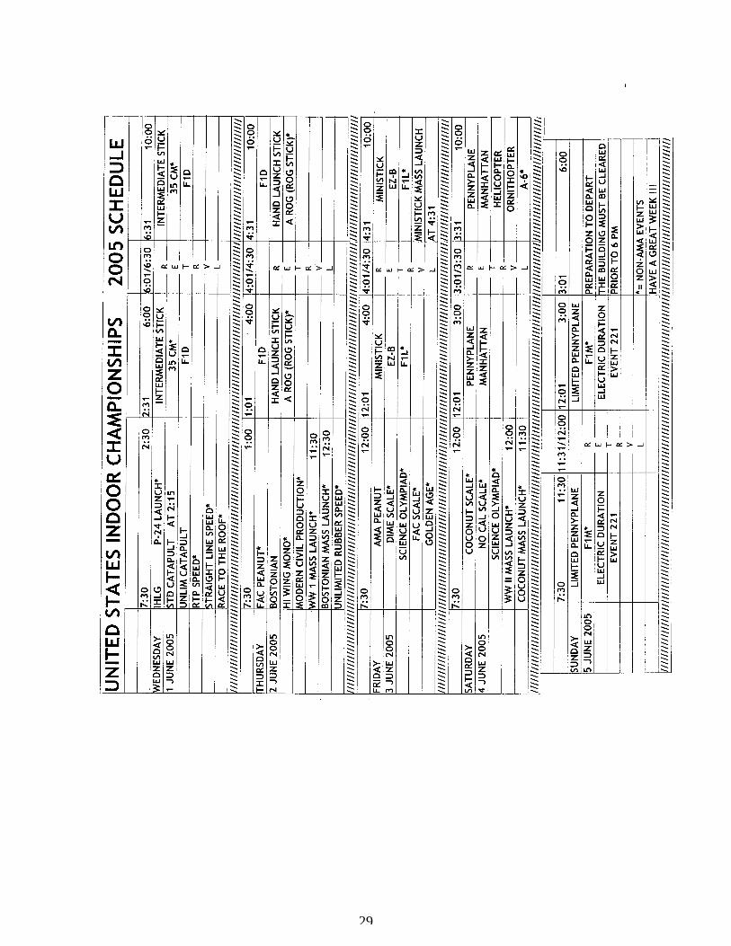
29
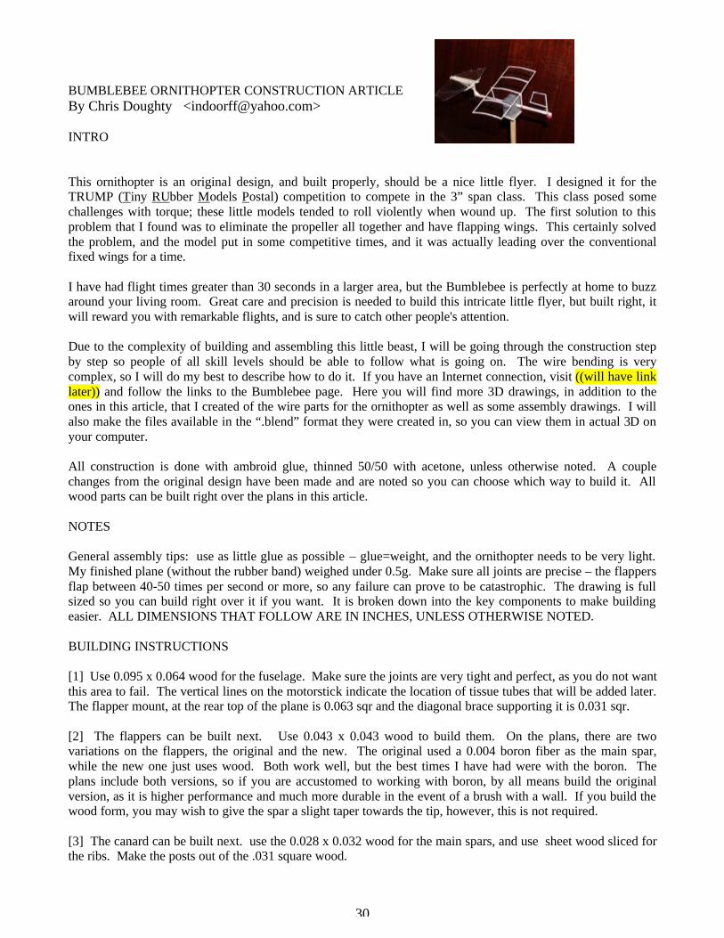
30
BUMBLEBEE ORNITHOPTER CONSTRUCTION ARTICLE By Chris Doughty <[email protected]> INTRO This ornithopter is an original design, and built properly, should be a nice little flyer. I designed it for the TRUMP (Tiny RUbber Models Postal) competition to compete in the 3” span class. This class posed some challenges with torque; these little models tended to roll violently when wound up. The first solution to this problem that I found was to eliminate the propeller all together and have flapping wings. This certainly solved the problem, and the model put in some competitive times, and it was actually leading over the conventional fixed wings for a time. I have had flight times greater than 30 seconds in a larger area, but the Bumblebee is perfectly at home to buzz around your living room. Great care and precision is needed to build this intricate little flyer, but built right, it will reward you with remarkable flights, and is sure to catch other people's attention. Due to the complexity of building and assembling this little beast, I will be going through the construction step by step so people of all skill levels should be able to follow what is going on. The wire bending is very complex, so I will do my best to describe how to do it. If you have an Internet connection, visit ((will have link later)) and follow the links to the Bumblebee page. Here you will find more 3D drawings, in addition to the ones in this article, that I created of the wire parts for the ornithopter as well as some assembly drawings. I will also make the files available in the “.blend” format they were created in, so you can view them in actual 3D on your computer. All construction is done with ambroid glue, thinned 50/50 with acetone, unless otherwise noted. A couple changes from the original design have been made and are noted so you can choose which way to build it. All wood parts can be built right over the plans in this article. NOTES General assembly tips: use as little glue as possible – glue=weight, and the ornithopter needs to be very light. My finished plane (without the rubber band) weighed under 0.5g. Make sure all joints are precise – the flappers flap between 40-50 times per second or more, so any failure can prove to be catastrophic. The drawing is full sized so you can build right over it if you want. It is broken down into the key components to make building easier. ALL DIMENSIONS THAT FOLLOW ARE IN INCHES, UNLESS OTHERWISE NOTED. BUILDING INSTRUCTIONS [1] Use 0.095 x 0.064 wood for the fuselage. Make sure the joints are very tight and perfect, as you do not want this area to fail. The vertical lines on the motorstick indicate the location of tissue tubes that will be added later. The flapper mount, at the rear top of the plane is 0.063 sqr and the diagonal brace supporting it is 0.031 sqr. [2] The flappers can be built next. Use 0.043 x 0.043 wood to build them. On the plans, there are two variations on the flappers, the original and the new. The original used a 0.004 boron fiber as the main spar, while the new one just uses wood. Both work well, but the best times I have had were with the boron. The plans include both versions, so if you are accustomed to working with boron, by all means build the original version, as it is higher performance and much more durable in the event of a brush with a wall. If you build the wood form, you may wish to give the spar a slight taper towards the tip, however, this is not required. [3] The canard can be built next. use the 0.028 x 0.032 wood for the main spars, and use sheet wood sliced for the ribs. Make the posts out of the .031 square wood.

31
[4] Build the rudder next. For the outline, use 0.026 x 0.020 wood, and for the post, use 0.031 x 0.031. The boom can be made from 0.031 x 0.028 balsa, cut to length as per the drawing. There you go. You have now finished building up all the structures/flying surfaces for the model. So much for the easy part! [5] Wing wire bending - use 0.005 piano wire for all wing wires. Due to the complex 3d shapes the wires must be bent into, please see the 3D drawings provided. Start by bending the wire shown in Fig. 1 below. This mounts on the underside of your wing and is where the conrods attach. Now bend wires shown in Fig. 2 and 3, and that will be all that needs to be done for the wing. The wire in Fig. 2 mounts on the bottom of the wing and serves to hold the flapper to the fuselage, allowing it to pivot up and down. The wire in Fig. 3 also does this, but at the rear section of the wing. Mount all 3 of these wires now. See Fig. 5 for locations. Try to be as precise as possible without driving yourself crazy. The closer you are to the indicated dimensions, the more predictable your plane will fly. I cannot guarantee what kind of flight characteristics will develop if your wire lengths are far off. [6] Bend the crank next. See Fig. 4. Bend the crank out of the 0.009 wire. It is important in the crank to make the bends as crisp and as close to 90 degrees as possible. [7] Making the conrods. This is a relatively easy step. Use 0.005 wire for them. The holes are 0.86 apart. A good way to do this is to make a jig using a piece of hard balsa or basswood that is .25 sqr. Get two scraps of .009 wire and poke them into the wood at 0.86 apart, leaving about 0.125 sticking out of the top. Wick some thin CA around the base of the wire so they will not pull out. Use this jig to wrap .005 wire around the two pins making a conrod with a hole in each end that are 0.86 apart. See plans for a diagram of the jig and conrods. [8] Now make a wire pigtail bearing out of the 0.009 wire to hold the crank in. Glue the pigtail bearing to the side of the fuselage at the end, use the fuselage side view as a guide. [9] Bend a rubber hook out of .009 wire for the front of the ornithopter as per the outline on the drawing. This is a simple 2d procedure, and not critical. Mount onto fuselage, as per the side view. There you go, you have now finished all the annoying wire bending! [10] Now we need to make the small rectangular bits of aluminum that the flapper wires will pivot in to provide the up/down motion of the wings. Take an aluminum can, and cut out a section of it. Flatten it, and sand it as thin as you dare with a fine grit sandpaper. Now cut two rectangles out of it that are 0.06 x 0.21. Take a scrap of .009 wire and gently twist and push it into the aluminum to make a hole in it. Make another hole 0.15 distance apart from the first. See the plans for the layout of the aluminum and holes. Now glue the aluminum to the wing mount, at the back top of the fuselage, one on each end. Orient the rectangle of aluminum so as the top side is the longest side. Use ambroid for this. See the Fig. 5 for more detail. [11] Covering can be done next. The original model was covered with ultrafilm on the flappers, but I have also used condensor paper with good results. The adhesive I used for attaching the ultrafilm was simply sugar and water, if you decide to go that route. I recommend pre-shrinking the condenser paper first, so as not to warp the wings with changes in humidity. The original model had a microfilm covered canard and vertical stabilizer, but this proved to be fragile, and unnecessary. The model needed some nose ballast, so condenser paper can be used on both these flying surfaces with no net gain in weight. See the drawing for the pattern of the flapper fabric. There are two versions of flapper on the drawing. Try them both and see which one works best for you. The more angular one of the two requires a membrane stiffener to be glued to the covering on the underside. This is

32
.018 x .028 wood. Do not glue this stiffener to anything except the fabric itself. The more rounded version of the flapper requires more slack in the fabric. The template reflects this, and if cut out properly, and glued to the spars, it should give you the correct amount of slack. Use a thinned down white glue to attach the covering to the wood structure. [12] At last, the part you have been waiting for, time for the final assembly. Mount the flappers as shown in Fig. 5, with Teflon washers where shown in the plan. To keep them sliding off, build up the end of the wire with ambroid big enough so it cannot slide back through the hole. Make tissue tubes using a scrap of the canard posts as a mandrel. You should have square tubes, so it fits tight with the canard posts. Do maybe about 5 wraps of the tissue, applying glue to it as your wrapping. When the desired number of wraps are reached, let glue dry. Then soften again with some acetone, and slide off mandrel. Glue the tubes (2 for canard, and one round one for the rudder) to the locations on shown on the fuselage drawing and the boom. Put the crank into the pigtail bearing you made and mounted to the fuselage, with a teflon washer between the bearing end and the crank to reduce friction. Now connect up the conrods as shown in Fig. 5. Again, to keep them from sliding back off, build up the end of the wire with ambroid just large enough that the conrods cannot slide off backwards. Mount the canard and the rudder in the tissue sockets now and glue the boom at the location shown on the drawings. ALTERNATIVE: I have recently found that flight performance MAY be improved by putting both the conrods on the same location on the crank, the location closest to the rest of the plane. This makes the wings go up and down more or less together, and seems to help eliminate the side to side rocking motion that will cause a decrease in lift and thrust. FLYING YOUR ORNITHOPTER The Bumblebee is not an easy plane to get flying, so here are a few tips to get you started in trimming for flight. The rubber for the motor should be stripped as thin as possible, right to the limit of what your rubber stripper is capable of. If you don't wreck a few trying to strip them, it is probably too thick. It is very important to make sure there is absolutely no binding anywhere in the flapper mechanism. Without the rubber band, and the wings in the up position, they should be able to fall back to the down position freely, just by gravity alone. If they don't, something is binding somewhere and needs to be fixed. Small amounts of clay can be added to the nose if necessary to bring the center of gravity to the correct location. This location depends on the flying characteristics of your model. Basically, you want it on the verge of stalling once the power starts to drop off. You may find the plane has a tendency to turn one way quite sharply, and you need a huge rudder input to correct this. This probably means you fabric on your wings is not quite the same tension, and one is developing more thrust than the other. If this is the case, you may wish to recover the wings, being careful to try to keep the tensions equal on both wing fabrics. If your ornithopter is still flying terribly, like diving into the ground, try winding the rubber the opposite way. You may not think this makes a difference, but it does! It is probably the single most noticeable adjustment you can make, and it will either cause the ornithopter to dive violently, or make it fly nice. I have found with mine that it likes to be wound the opposite way you would wind a normal propeller driven airplane. If your plane still does not fly, the best advice i can give is just keep experimenting. Check all the critical wire lengths, or try re-covering the flappers with fabric that is a different tension. It takes quite a while to get it trimmed for a nice flight, but it will fly! If you have any questions while building, feel free to email me. I hope you enjoy building and flying this little plane.

33
DIAGRAMS
Figure 1
Figure 2
Figure 3
0.238 0.028
0.117
0.165
0.028
0.410
0.165
0.405
0.028

34
Figure 4
Fig. 5 -- Rear view of Bumblebee
0.50
0.25
0.154
0.083
0.154
900 between these, adjust as required.
See Fig. 1
See Fig. 2
See Fig. 3
See Fig. 4
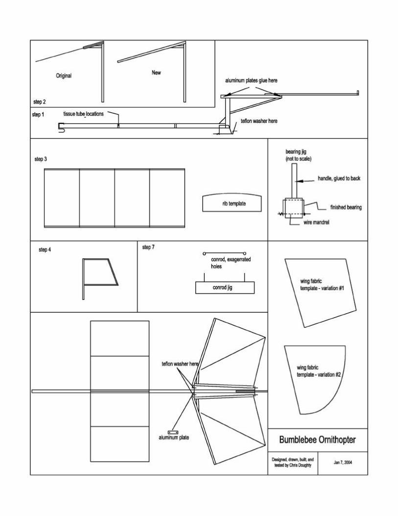
35

36
Sanding Apparatus for Thin Balsa Sheets, Bruno Waechter, W. Ger., from INAV #71
F1D thoughts By Andras Ree
By now we have completed four contest seasons with the new F1D rules including two World championships and one European. So, it is possible to have a look on the facts, how the rules are working, how the expectations are fulfilled. Quite a long time ago Tim Goldstein asked me to write such a paper being more or less the originator and supporter of the new rule set and the one who managed the rule change. I apologize publicly it took so long time because of my very busy life, but this way I could take the advantage to have more experience with the rules. Let me start with the words of Laurie Barr, that we had and still have ...not just F1D but more or less a general “indoor” crisis, existing on national champs level also, or even down. Just the money talks, practically no one wants to “sponsor” us by not asking for high rental fees from a 100 percent non-profit “civil” activity. We are not a circus in any respect for the public, we can not put advertisements on our “aircrafts”, we are not interesting for the media (or just for three minutes). That was (and still is) only one aspect besides others, that led to the idea to change the F1D rules. At that time Hungary was the reigning world champion team, I was close second, so we took this position to propose the changes after several test flights and consultations, also international ones. We did not want to call for a vote, just collected the different arguments. Having the necessary international experience I became the front person of this activity and I made the final wording of the proposal, but the new F1D parameters were formulated from several ideas from different persons. The span value was based on the data collected by Rich Doig from airline regulations (23”x16”x9” max. cabin luggage size), to fit the boxes to the overhead lockers, the limited stab span (and other contributions) from Bernard Hunt to avoid the tandems, the rubber weight value came from my test flights, also the wing chord limit to avoid extreme wings and loosing the advantage of the higher minimum weight. At the same time France also made a rather similar proposal. After the rule changes I have got and seen many different opinions, cold and warm as well, probably more cold than warm. After a while (about two seasons and after) the ratio has changed to the opposite, I have seen also enthusiastic opinions, and even I have got apologizing message as well. Of course cold ones are still exist.

37
At the time when the rule changes were argued a lot, there was one unique message from the indoor fraternity saying: …The expert is expert, the rules are irrelevant and the same for everybody, therefore don’t argue, work and fly instead… The sender of the message to the indoor list was Jim Richmond. His indoor career fully confirms his message. Since this message he has got both world champion titles, also made a Cat III world record. Before, since his first title (Rome 1968) he was world champion with all the F1D rule sets (65 cm 1 time; 65 cm and 1 g model 5 times), all together he has got eight individual titles by now and made several world records. Applying the new rules the expectations were:
1. Easier to build to weight; 2. Use plastic cover besides microfilm without weight penalty; 3. Less need for extra quality wood; 4. Have more durable models; 5. Easier to travel with much smaller boxes and less damage; 6. Keep the unique flying style and beauty of the F1D models; 7. Have lower performance; 8. Less need to use VP in higher sites; 9. Better use of the available lower sites; 10. Have more newcomer and even “oldcomer”; 11. Have more organizers.
I believe the first six expectations have been fulfilled. Build to weight is easier now, the plastic cover became widely used, the wood selection is not as much critical as before. As just recently Steve Brown expressed the durability of the models is much better. By my mind it is true for the flight, steering, collisions and transportation as well. This durability is caused by the stronger constructions and the plastic cover (by using the higher minimum weight). The plastic covered unbraced wings are great and made it possible to use really small boxes. Traveling with the small boxes with no damages is just perfect compared with the previous wardrobe like boxes. We could keep the flying style and beauty of our models, because the main influencing parameter, the surface loading was intentionally adjusted to be in the same range as before. The visitors are still shocked when they see our models flying. The plastic covering shows a bit less beauty, but when precisely done it is also nice. This way we still can say after about twenty years with Jorgen Korsgaard (the founder of the European indoor newsletter) …indoor is beautiful… The performance has been reduced, but after four season, it is clear, that not as much as expected. In the first year the reduction looked OK (times below 30 min.), but later in the high sites like the salt mine, different hangers and other places the times were raised to well over 30 minutes. In addition to that, in the new (but already lost) best ever site, the Cargo Lifter hanger, the high times were over the unbelievable 40 minutes. Probably these 40+ times are close to the overall potential of the present F1D models when using the best rubber batches, because the Cargo Lifter proved to be “infinitely” high, where not one of the models touched the roof. The performance in this site was of a unique, unexpected level, because of not having to back off before launch (using the initial burst as well) and the unbraced models have less drag, so this way the best models could gain more height. The overall performance reduction in Cat IV is about 8-9 minutes. By now, there is no need to use VP props only in the Cargo Lifter and the salt mine. It looks true for the first site forever, but for the mine I am not 100 percent sure when looking at the flaring prop of Jim Richmond, several ceiling scrubbing models and the 33+ VP flight of Fred Tellier. Practically, in all recently used lower sites the VP (and the VD for Jim Richmond) is at an advantage over the fixed pitch props. (The firstly proposed 0.5 g rubber would have been better in this respect.) Of course, because of the limited available energy and the lower overall prop efficiency the times are well below the Cargo Lifter times. (With the old rules we used more rubber with the VP props.) All in all, because of the fast changes in the model design and flying style (to fit to the new conditions) the performance reduction was overestimated, and the necessity for using the VP (in higher sites) was underestimated. There are some changes in the usage of lower sites, because there is more reduction in the performances. In Cat III sites the reduction is about 10-11 minutes and in Cat II sites about 13-14 minutes. In these sites less models

38
can fly simultaneously (in some cases not more than only 2), so the shorter times give better organizational conditions. The expected more newcomer and “oldcomer” are here, we also have more participating countries – the increase is fine, but still not enough. Just recently Alan Cohen pointed out …the new rules, by design, attracted many new flyers and brought back some experienced ones… Maybe the best example is the very successful American junior team. By my knowledge, none of them were flying old rule F1Ds, none of them are family members, relatives or neighbors of any experienced indoor flyer. But, there was the SO program and the several mentors behind the success, so the solution is more complex and goes back to the long time existing problem that more efforts are needed to help the newcomers, mainly the young ones. I do not remember for the exact origin of the question to be put in front of us in our modeling workshop: Have you helped a junior today? One of the most critical problems is to have more organizers. Recently UK was back (2003 European Champs) plus France (2005 E/Ch) and Serbia & Montenegro (bid for 2007 E/Ch) are new as organizers, but the need is still valid first of all for world champs. Of course this problem is closely connected to the usable sites. Usable in this respect means that the site is suitable for our purpose, getting a proper time window for a champ besides the other programs of the site is possible and the financial conditions are acceptable. Unfortunately in the past few years we have lost regularly used sites because of different reasons, and some others became not accessible just because of financial reasons. In addition to this we have lost the, only recently gained, unique and best ever indoor site, the Cargo Lifter hanger as well. Just for example we have lost the highest suitable site in Hungary, the traditional site of our nationals since 50 years, the site of the 1966 world champs in Debrecen. Since last year the owner, the University of Debrecen, does not accept less than the market price of renting for our non profit civil activity (see the words of Laurie at the beginning of this paper) even if the site would be empty otherwise. Here we are now, in this part of the world as well. But, and again, this situation is not because of the new F1D rules. Applying the new rules some expressed concerns were:
1. Bigger effect of the rubber quality; 2. Rubber measuring problems; 3. Level the playground; 4. Harder to steer the new models.
As some others before, now Alan expressed the concern of the bigger effect of rubber quality, but it was like that always. It really counts only at the highest level, because it is much more important to fit the well trimmed the model, prop, rubber and VP (if used) to each other and all together to the given conditions. This can be done perfectly only by the best indoor personalities with a lot of efforts. Rather different models can fly very well at the same conditions. I will never forget when in Rome (1968) the two mostly different models (Richmond and Kalina) placed first and second. Recently the 5/99 and other good batches are also used in the second half of the world champs listings, and the contrary, the nowadays rather successful Lutz Schramm has no 5/99. On the other hand the lack of access to top rubbers may become a real problem in a while, but not because of the new rules. It will affect not only newcomers but others as well. It is the same for the F1B class just they will be out of the good batches earlier. A recent dispute on the indoor list raised this problem up, started by Slobodan Midic, proposing to fly at champs only the rubber distributed by the organizer, but the present situation was well explained by Mark Bennett, Alan Cohen and Tim Goldstein. I fully agree with them looking at my example. I was rather competitive before the rule changes even in high sites (what we do not have at home) because of the work I have done and the experience I have collected through the decades. With the new rules I perform well in the lower home sites, but not yet at the previous level in high sites. It is simply because of the not enough effort. It was not intentional of course, just because of the lack of time, so I am in a delay. Some years ago I have seen a saying written on the wall of a gym: No pain – no gain. I had not enough pain yet… Rubber measuring problems were also predicted, but the practice proved, we do not have real problems. Suitable digital scales are available at a reasonable price, and the practice to check the rubber weight only after the flight, and no check below an announced basic flight time and from the third round if there was no improvement, works fine. That is just a joke of the life that by my knowledge I was the first and only one at the international level by now who has got zero for an official flight because of rubber over weight. At the 2003 E/Ch in London close to the end of the third round I ran out of my prepared rubbers and got one from my teammate. He has checked the rubber before on his Tanita scale and I had no time to check the rubber on the official scale as I always do. I

39
wound very fast and launched the model just 10 seconds before the end signal. The flight was good, would push me to the second place, the team third, but the rubber on the official scale was slightly over the limit. How it happened? Next morning when cutting rubber we have got the answer. As everybody knows the rubber is getting static electric charge at cutting. Therefore we use a balsa podium on the scale to keep the rubber away from the plastic house of the Tanita scale and before measuring the weight we pull the rubber strip through in a carbon brush to reduce the charge. This time we could not measure the weight, the repeated measurements were distributed in about a 10 percent range. It never happened before. To solve the problem the scale, the brush and the rubber strips were earthed by the tap in the bathroom, the plastic covered surface of the table was cleaned by a wet towel and there was no more problem. The official scale was earthed… It was a rather expensive experience. Level the playground was another concern, but it did not happen, the two world and one European champs prove this. The results are a bit closer and new competitors were on the podium. Both are good, but still Jim is the world champion. The talent, skill and experience do not allow the playground to be leveled. It was also clearly expressed by LeRoy Cordes: As a competitor in other events I know that no matter what you do to the rules the cream will always rise to the top. I may also refer to Carlo Godel: Whiners will whine and winners will win. And the winners are the ones who put the most into their winning ... I can not really consider the harder to steer remark of Steve Brown, because in our lower home sites we are only using long sticks. Dezso Orsovai made perfect steering at big heights just recently in the salt mine. I can steer now with less risk than before, but I have to declare I am not a big steerer by balloon. Intentionally I did not react to any rough messages or remarks I read at the time of the rule changes. I think the reasons of these remarks were mainly the lack of information, experience and misunderstanding. Let me believe these reasons more or less have ceased by now. Recently there are different things bothering our hobby/sport. The limited availability of good rubber and the reduced number of usable sites were discussed before. The airliners have been reduced a bit the allowed cabin baggage sizes to 22”x16”x8” or 22”x14”x9”, but we are still not too much over with the length. We have lost the source of Y2K2 film, but the bit thicker film looks available for longer time. These are generating some new problems, but these are again not connected to the rule changes and hopefully will not destroy the class. Summary Looking at all the aspects I still believe, the positive side of the rule change is rather stronger than the negative. Maybe it is better to say that some expected goals were not reached at the level I (we) expected. I still want to believe in the future of F1D, we can at least slow down the declining of the class, and I hope not to reach the vision that Steve Brown expressed some years ago in his paper. It is our responsibility to do what we can within the more and more hard conditions. We have to work for our indoor community; need to put more work into our future, first of all into the young ones. We have to say thank you to those who are already doing this, like the INAV and IFI staff, the SO instructors and so on. I also have to mention one rather general experience coming from my 20 years of CIAM activity. The main obstacles to have changes are the majority of the current top fliers in any class even if the class is going to be ceased. Bernie Hunt underlined a simple fact around the rule change period that we never would be able to reach an agreement in possible changes therefore somebody had to take the risk to move without the warranty but with the hope to have success. Some addition to plastic covering For me it is still easier to cover by microfilm (having good microfilm made by Orsovai and a bit more than 50 years of experience) but by now I have learned it. We keep the surfaces on the jig for covering and we are using a water based, clear and cheap paper glue diluted very much by distilled water and some butanol: 9 cm3 distilled water + 1 cm3 butanol contains 5 drops of glue. First the glue is added to the water, the butanol just afterwards otherwise the fluid becomes milky. It is sticky enough, dries slow enough to leave time for arranging the film, and using water the connection can be solved if needed.

40
INAV
1309
6 W
Cro
ss D
rLi
ttleto
n CO
801
27