issue 06/2015 FLUIDS MECHANICS (ELEMENTARY ... mechanics module/0812...Bernoulli’s Theorem...
16
issue 06/2015 FLUIDS MECHANICS (ELEMENTARY). Advanced Module 1 / 5 Ref: 0812 ITEM REFERENCE DESCRIPTION QTY. LIFLUBA BASIC FLUIDS MECHANICS INTEGRATED LABORATORY, FORMED BY: 1 1 FME00 HYDRAULICS BENCH 1 2 FME02 FLOW OVER WEIRS 1 3 FME02/SOF FLOW OVER WEIRS DEMONSTRATION STUDENT/MODULE SOFTWARE 1 4 FME02/CAL COMPUTER AIDED LEARNING SYSTEM: FLOW OVER WEIRS STUDENT/MODULE SOFTWARE PACKAGE 1 5 FME04 ORIFICE DISCHARGE 1 6 FME04/SOF ORIFICE DISCHARGE DEMONSTRATION STUDENT/MODULE SOFTWARE 1 7 FME04/CAL COMPUTER AIDED LEARNING SYSTEM: ORIFICE DISCHARGE STUDENT/MODULE SOFTWARE PACKAGE 1 8 FME10 DEAD WEIGHT CALIBRATOR 1 9 FME10/SOF DEAD WEIGHT CALIBRATOR DEMONSTRATION STUDENT/MODULE SOFTWARE 1 10 FME10/CAL COMPUTER AIDED LEARNING SYSTEM: DEAD WEIGHT CALIBRATOR STUDENT/MODULE SOFTWARE PACKAGE 1 11 FME11 METACENTRIC HEIGHT 1 12 FME11/SOF METACENTRIC HEIGHT DEMONSTRATION STUDENT/MODULE SOFTWARE 1 13 FME11/CAL COMPUTER AIDED LEARNING SYSTEM: METACENTRIC HEIGHT STUDENT/MODULE SOFTWARE PACKAGE 1 14 FME14 FREE AND FORCED VORTICES 1 15 FME14/SOF FREE AND FORCED VORTICES DEMONSTRATION STUDENT/MODULE SOFTWARE 1 16 FME14/CAL COMPUTER AIDED LEARNING SYSTEM: FREE AND FORCED VORTICES DEMONSTRATION STUDENT/MODULE SOFTWARE PACKAGE 1 17 FME15 WATER HAMMER 1 18 FME15/SOF WATER HAMMER DEMONSTRATION STUDENT/MODULE SOFTWARE 1 19 FME15/CAL COMPUTER AIDED LEARNING SYSTEM: WATER HAMMER STUDENT/MODULE SOFTWARE PACKAGE 1 20 FME16 PELTON TURBINE 1 21 FME16/SOF PELTON TURBINE DEMONSTRATION STUDENT/MODULE SOFTWARE 1 22 FME16/CAL COMPUTER AIDED LEARNING SYSTEM: PELTON TURBINE STUDENT/MODULE SOFTWARE PACKAGE 1 23 FME17 ORIFICE AND FREE JET FLOW 1 24 FME17/SOF ORIFICE AND FREE JET FLOW DEMONSTRATION STUDENT/MODULE SOFTWARE 1 25 FME17/CAL COMPUTER AIDED LEARNING SYSTEM: ORIFICE AND FREE JET FLOW STUDENT/MODULE SOFTWARE PACKAGE 1 26 FME21 RADIAL FLOW TURBINE 1
Transcript of issue 06/2015 FLUIDS MECHANICS (ELEMENTARY ... mechanics module/0812...Bernoulli’s Theorem...
issue 06/2015
FLUIDS MECHANICS (ELEMENTARY). Advanced Module
1 / 5Ref: 0812
ITEM REFERENCE DESCRIPTION QTY.
LIFLUBA BASIC FLUIDS MECHANICS INTEGRATED LABORATORY, FORMED BY: 1
1 FME00 HYDRAULICS BENCH 1
2 FME02 FLOW OVER WEIRS 1
3 FME02/SOF FLOW OVER WEIRS DEMONSTRATION STUDENT/MODULE SOFTWARE 1
4 FME02/CAL COMPUTER AIDED LEARNING SYSTEM: FLOW OVER WEIRS STUDENT/MODULE SOFTWARE PACKAGE
1
5 FME04 ORIFICE DISCHARGE 1
6 FME04/SOF ORIFICE DISCHARGE DEMONSTRATION STUDENT/MODULE SOFTWARE 1
7 FME04/CAL COMPUTER AIDED LEARNING SYSTEM: ORIFICE DISCHARGE STUDENT/MODULE SOFTWARE PACKAGE
1
8 FME10 DEAD WEIGHT CALIBRATOR 1
9 FME10/SOF DEAD WEIGHT CALIBRATOR DEMONSTRATION STUDENT/MODULE SOFTWARE
1
10 FME10/CAL COMPUTER AIDED LEARNING SYSTEM: DEAD WEIGHT CALIBRATOR STUDENT/MODULE SOFTWARE PACKAGE
1
11 FME11 METACENTRIC HEIGHT 1
12 FME11/SOF METACENTRIC HEIGHT DEMONSTRATION STUDENT/MODULE SOFTWARE 1
13 FME11/CAL COMPUTER AIDED LEARNING SYSTEM: METACENTRIC HEIGHT STUDENT/MODULE SOFTWARE PACKAGE
1
14 FME14 FREE AND FORCED VORTICES 1
15 FME14/SOF FREE AND FORCED VORTICES DEMONSTRATION STUDENT/MODULE SOFTWARE
1
16 FME14/CAL COMPUTER AIDED LEARNING SYSTEM: FREE AND FORCED VORTICES DEMONSTRATION STUDENT/MODULE SOFTWARE PACKAGE
1
17 FME15 WATER HAMMER 1
18 FME15/SOF WATER HAMMER DEMONSTRATION STUDENT/MODULE SOFTWARE 1
19 FME15/CAL COMPUTER AIDED LEARNING SYSTEM: WATER HAMMER STUDENT/MODULE SOFTWARE PACKAGE
1
20 FME16 PELTON TURBINE 1
21 FME16/SOF PELTON TURBINE DEMONSTRATION STUDENT/MODULE SOFTWARE 1
22 FME16/CAL COMPUTER AIDED LEARNING SYSTEM: PELTON TURBINE STUDENT/MODULE SOFTWARE PACKAGE
1
23 FME17 ORIFICE AND FREE JET FLOW 1
24 FME17/SOF ORIFICE AND FREE JET FLOW DEMONSTRATION STUDENT/MODULE SOFTWARE
1
25 FME17/CAL COMPUTER AIDED LEARNING SYSTEM: ORIFICE AND FREE JET FLOW STUDENT/MODULE SOFTWARE PACKAGE
1
26 FME21 RADIAL FLOW TURBINE 1
2 / 5Ref: 0812
27 FME21/SOF RADIAL FLOW TURBINE DEMONSTRATION STUDENT/MODULE SOFTWARE 1
28 FME21/CAL COMPUTER AIDED LEARNING SYSTEM: RADIAL FLOW TURBINE SOFTWARE 1
29 FME22 VENTURI, BERNOULLI AND CAVITATION EQUIPMENT. 1
30 FME22/SOF VENTURY, BERNOULLI AND CAVITATION EQUIPMENT DEMONSTRATION STUDENT/MODULE SOFTWARE
1
31 FME22/CAL COMPUTER AIDED LEARNING SYSTEM: VENTURY, BERNOULLI AND CAVITATION EQUIPMENT STUDENT/MODULE SOFTWARE PACKAGE
1
32 FME23 BASIC PIPE NETWORK UNIT 1
33 FME23/SOF BASIC PIPE NETWORK EQUIPMENT DEMONSTRATION STUDENT/MODULE SOFTWARE
1
34 FME23/CAL COMPUTER AIDED LEARNING SYSTEM: BASIC PIPE NETWORK EQUIPMENT SOFTWARE
1
35 FME24 UNIT FOR THE STUDY OF POROUS BEDS IN VENTURI TUBES (DARCY´S EQUATION)
1
36 FME24/SOF EQUIPMENT FOR THE STUDY OF THE DARCY´S EQUATION DEMOSTRATION STUDENT/MODULE SOFTWARE
1
37 FME24/CAL COMPUTER AIDED LEARNING SYSTEM:EQUIPMENT FOR THE STUDY OF THE DARCY´S EQUATION STUDENT/MODULE SOFTWARE PACKAGE
1
38 FME25 FLOW CHANNEL, 1 M. LENGHT (WITHOUT ACCESSORIES) 1
39 FME25/SOF FLOW CHANNEL, 1 M. LENGHT DEMOSTRATION STUDENT/MODULE SOFTWARE
1
40 FME25/CAL COMPUTER AIDED LEARNING SYSTEM:FLOW CHANNEL, 1 M. LENGHT STUDENT/MODULE SOFTWARE PACKAGE
1
41 FME25/A ACCESORIES FOR FLOW CHANNEL, 1M. LENGHT. FORMED BY: 1
FME25TP PITOT TUBE 1
FME25CV VERTICAL FLAT GATE 1
FME25SDL SYPHON SPILLWAY 1
FME25RM SCALE TO MEASURE THE WATER LEVEL (LIMNIMETER) 1
42 FME26 DEPRESSION MEASUREMENT SYSTEM (VACUUM GAGE) 1
43 FME26/SOF DEPRESSION MEASUREMENT SYSTEM DEMOSTRATION STUDENT/MODULE SOFTWARE
1
44 FME26/CAL COMPUTER AIDED LEARNING SYSTEM: DEPRESSION MEASUREMENT SYSTEM STUDENT/MODULE SOFTWARE PACKAGE
1
45 FME27 AXIAL FLOW TURBINE 1
46 FME27/SOF AXIAL FLOW TURBINE DEMONSTRATION STUDENT/MODULE SOFTWARE 1
47 FME27/CAL COMPUTER AIDED LEARNING SYSTEM: AXIAL FLOW TURBINE SOFTWARE 1
48 FME28 FRANCIS TURBINE 1
49 FME28/SOF FRANCIS TURBINE DEMONSTRATION STUDENT/MODULE SOFTWARE 1
50 FME28/CAL COMPUTER AIDED LEARNING SYSTEM: FRANCIS TURBINE 1
51 FME29 KAPLAN TURBINE 1
52 FME29/SOF KAPLAN TURBINE DEMONSTRATION STUDENT/MODULE SOFTWARE 1
3 / 5Ref: 0812
53 FME29/CAL COMPUTER AIDED LEARNING SYSTEM: KAPLAN TURBINE 1
54 FME30 VORTEX FLOW METER 1
55 FME30/SOF VORTEX FLOW METER STUDENT/MODULE SOFTWARE 1
56 FME30/CAL COMPUTER AIDED LEARNING SYSTEM: VORTEX FLOW METER STUDENT/MODULE SOFTWARE PACKAGE
1
57 FME31 HORIZONTAL OSBORNE-REYNOLDS DEMONSTRATION. 1
58 FME31/SOF HORIZONTAL OSBORNE-REYNOLDS DEMONSTRATION STUDENT/MODULE SOFTWARE
1
59 FME31/CAL COMPUTER AIDED LEARNING SYSTEM: HORIZONTAL OSBORNE-REYNOLDS DEMONSTRATION STUDENT/MODULE SOFTWARE PACKAGE
1
60 FME32 PITOT STATIC TUBE MODULE 1
61 FME32/SOF PITOT STATIC TUBE MODULE STUDENT/MODULE SOFTWARE 1
62 FME32/CAL COMPUTER AIDED LEARNING SYSTEM: PITOT STATIC TUBE MODULE STUDENT/MODULE SOFTWARE PACKAGE
1
63 INS/SOF CLASSROOM MANAGEMENT SOFTWARE PACKAGE (INSTRUCTOR SOFTWARE). ONLY ONE IS REQUIRED AND COMMON FOR ALL SOFTWARE PACKAGES (STUDENT/MODULE SOFTWARE) TYPE ".../SOF"
1
64 BDAS BASIC DATA ADQUISITION SYSTEM FROM COMPUTER AND SENSORS FOR BEING USED WITH EDIBON FME SERIES, FORMED BY:
1
BDAS/BFA ELECTRONIC BOX, DATA ACQUISITION BOARD & SOFTWARE 1
FME02/BDAS-BFI
SPECIFIC SOFTWARE AND ACCESSORIES FOR FME02 1
FME04/BDAS-BFI
SPECIFIC SOFTWARE AND ACCESSORIES FOR FME04 1
FME10/BDAS-BFI
SPECIFIC SOFTWARE AND ACCESSORIES FOR FME10 1
FME11/BDAS-BFI
SPECIFIC SOFTWARE AND ACCESSORIES FOR FME11 1
FME14/BDAS-BFI
SPECIFIC SOFTWARE AND ACCESSORIES FOR FME14 1
FME15/BDAS-BFI
SPECIFIC SOFTWARE AND ACCESSORIES FOR FME15 1
FME16/BDAS-BFI
SPECIFIC SOFTWARE AND ACCESSORIES FOR FME16 1
FME17/BDAS-BFI
SPECIFIC SOFTWARE AND ACCESSORIES FOR FME17 1
FME21/BDAS-BFI
SPECIFIC SOFTWARE AND ACCESSORIES FOR FME21 1
FME22/BDAS-BFI
SPECIFIC SOFTWARE AND ACCESSORIES FOR FME22 1
FME23/BDAS-BFI
SPECIFIC SOFTWARE AND ACCESSORIES FOR FME23 1
FME24/BDAS-BFI
SPECIFIC SOFTWARE AND ACCESSORIES FOR FME24 1
4 / 5Ref: 0812
64 FME25/BDAS-BFI
SPECIFIC ACCESSORIES AND SENSORS FOR FME25 1
FME26/BDAS-BFI
SPECIFIC SOFTWARE AND ACCESSORIES FOR FME26 1
FME27/BDAS-BFI
SPECIFIC SOFTWARE AND ACCESSORIES FOR FME27 1
FME28/BDAS-BFI
SPECIFIC SOFTWARE AND ACCESSORIES FOR FME28 1
FME29/BDAS-BFI
SPECIFIC SOFTWARE AND ACCESSORIES FOR FME29 1
FME30/BDAS-BFI
SPECIFIC SOFTWARE AND ACCESSORIES FOR FME30 1
FME31/BDAS-BFI
SPECIFIC SOFTWARE AND ACCESSORIES FOR FME31 1
FME32/BDAS-BFI
SPECIFIC SOFTWARE AND ACCESSORIES FOR FME32 1
Notes:
OTHER ITEMS INCLUDED:
1) Multipost option:
This module has only one unit for each item, but we can recommend the number of units for 10 or 30 students working simultaneously.
2) Supply conditions:
a) Technical conditions included:
- Laboratories adaptation.
- Installation of all units supplied.
- Starting up for all units.
- Training about the exercises to be done with any unit.
- Teacher training related with t and the teaching unit and the teaching techniques uses.
- Technology transfer.
b) Commercial conditions:
- Packing.
- Financing charges.
- C.I.F. charges.
c) Others conditions:
- 8 Manuals for each EDIBON teaching unit:
. Required services manual.
. Assembly and installation manual.
. Interface and software/control console manual.
. Set in operation manual.
. Safety norms manual.
. Practices manual.
COMPONENTS AND SPARE PARTSPARTS 1*COMPLEMENTARY ITEMPA 1*INSTALLATION AND STARTING-UPIYPM 1*TRAINING AND BRINGING UP TO DATE OF TEACAPRO 1*TEACHING TECHNIQUE "KNOW-HOW"TD 1*DOCUMENTATION AND MANUALSMANU 1*

5 / 5Ref: 0812
. Maintenance manual.
. Calibration manual.
PC
Page 6
�
�
�
�
�
General conceptsPipes
Hydraulic Machines
Demonstration
Laws
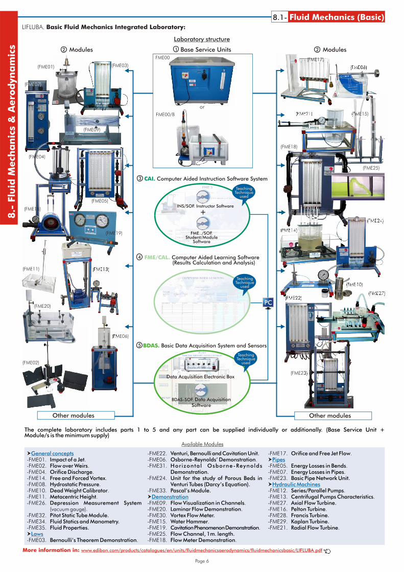
-FME22. Venturi, Bernoulli and Cavitation Unit. -FME17. Orifice and Free Jet Flow.-FME01. Impact of a Jet. -FME06. Osborne-Reynolds’ Demonstration.-FME02. Flow over Weirs. -FME31. Horizontal Osborne-Reynolds -FME05. Energy Losses in Bends.-FME04. Orifice Discharge. Demonstration. -FME07. Energy Losses in Pipes.-FME14. Free and Forced Vortex. -FME24. Unit for the study of Porous Beds in -FME23. Basic Pipe Network Unit.-FME08. Hydrostatic Pressure. Venturi Tubes (Darcy’s Equation).-FME10. Dead Weight Calibrator. -FME33. Pascal’s Module. -FME12. Series/Parallel Pumps.-FME11. Metacentric Height. -FME13. Centrifugal Pumps Characteristics.-FME26. Depression Measurement System -FME09. Flow Visualization in Channels. -FME27. Axial Flow Turbine.
(vacuum gauge). -FME20. Laminar Flow Demonstration. -FME16. Pelton Turbine.-FME32. Pitot Static Tube Module. -FME30. Vortex Flow Meter. -FME28. Francis Turbine.-FME34. Fluid Statics and Manometry. -FME15. Water Hammer. -FME29. Kaplan Turbine.-FME35. Fluid Properties. -FME19. Cavitation Phenomenon Demonstration. -FME21. Radial Flow Turbine.
-FME25. Flow Channel, 1m. length.-FME03. Bernoulli’s Theorem Demonstration. -FME18. Flow Meter Demonstration.
Available Modules
The complete laboratory includes parts 1 to 5 and any part can be supplied individually or additionally. (Base Service Unit + Module/s is the minimum supply)
More information in: www.edibon.com/products/catalogues/en/units/fluidmechanicsaerodynamics/fluidmechanicsbasic/LIFLUBA.pdf
LIFLUBA. Basic Fluid Mechanics Integrated Laboratory:
8.1- Fluid Mechanics (Basic)8.-
Flu
idM
ech
an
ics
&A
ero
dyn
am
ics Modules Base Service Units
CAI. Computer Aided Instruction Software System
12
3
FME/CAL. Computer Aided Learning Software (Results Calculation and Analysis)
Laboratory structure
Other modules Other modules
4
5 BDAS. Basic Data Acquisition System and Sensors
(FME07)
(FME03)(FME01)
(FME09)
(FME20)
(FME13)
(FME02)
(FME11)
(FME08)
(FME15)(FME21)
(FME14)
(FME23)
(FME17)FME00
or
FME00/B
FME../SOF.Student/Module
Software
+INS/SOF. Instructor Software
TeachingTechnique
used
TeachingTechnique
used
BDAS-SOF. Data AcquisitionSoftware
Data Acquisition Electronic Box
TeachingTechnique
used
(FME05)
Modules2
(FME04)
(FME16)
(FME19)
(FME06)
(FME22)
(FME10)
(FME27)
(FME18)
(FME25)
(FME24)
LIFLUBA. Basic Fluid Mechanics Integrated Laboratory:
Modules2
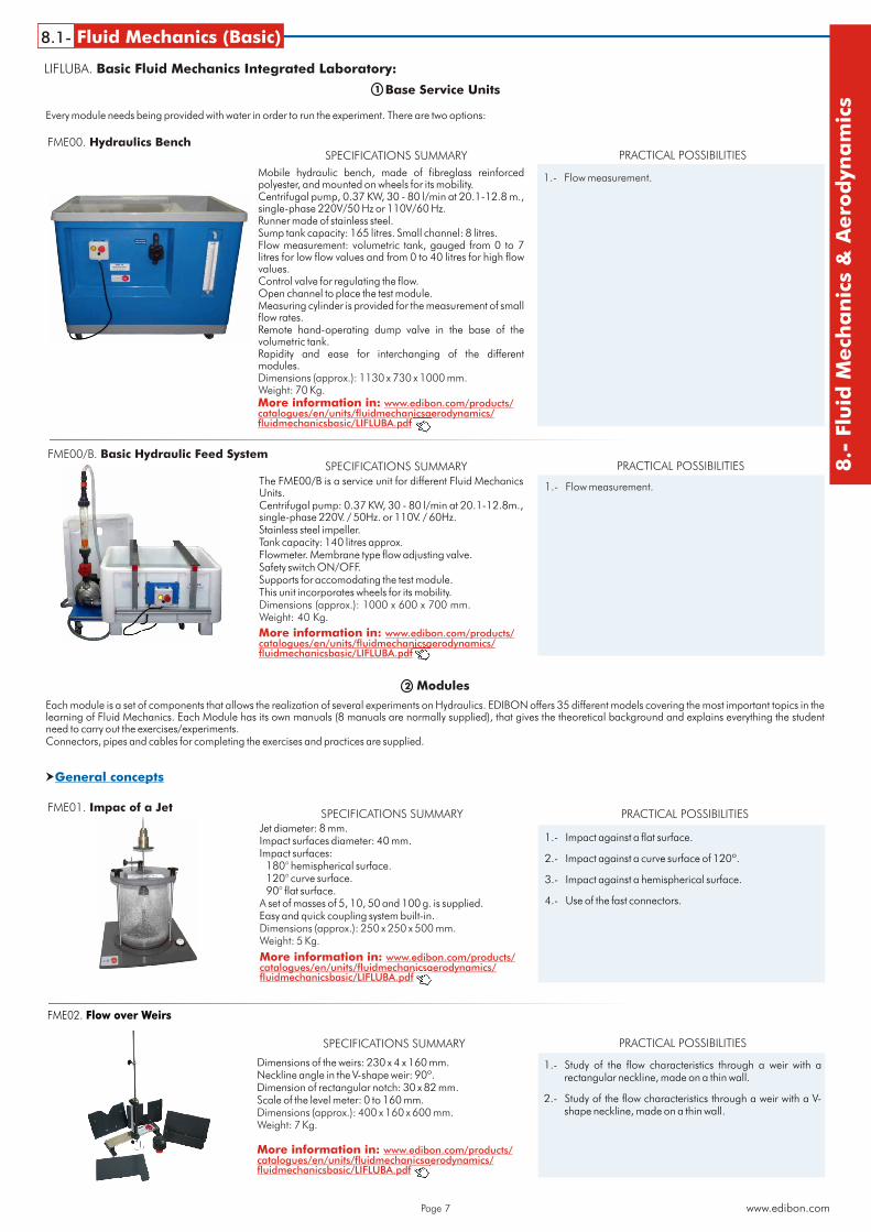
Jet diameter: 8 mm. Impact surfaces diameter: 40 mm. Impact surfaces:
180° hemispherical surface. 120° curve surface. 90° flat surface.
A set of masses of 5, 10, 50 and 100 g. is supplied.Easy and quick coupling system built-in.Dimensions (approx.): 250 x 250 x 500 mm. Weight: 5 Kg.
FME01. Impac of a Jet
Base Service Units
SPECIFICATIONS SUMMARY
Mobile hydraulic bench, made of fibreglass reinforced polyester, and mounted on wheels for its mobility.Centrifugal pump, 0.37 KW, 30 - 80 l/min at 20.1-12.8 m., single-phase 220V/50 Hz or 110V/60 Hz.Runner made of stainless steel. Sump tank capacity: 165 litres. Small channel: 8 litres. Flow measurement: volumetric tank, gauged from 0 to 7 litres for low flow values and from 0 to 40 litres for high flow values.Control valve for regulating the flow.Open channel to place the test module. Measuring cylinder is provided for the measurement of small flow rates. Remote hand-operating dump valve in the base of the volumetric tank. Rapidity and ease for interchanging of the different modules.Dimensions (approx.): 1130 x 730 x 1000 mm.Weight: 70 Kg.
The FME00/B is a service unit for different Fluid Mechanics Units.Centrifugal pump: 0.37 KW, 30 - 80 l/min at 20.1-12.8m., single-phase 220V. / 50Hz. or 110V. / 60Hz.Stainless steel impeller.Tank capacity: 140 litres approx. Flowmeter. Membrane type flow adjusting valve. Safety switch ON/OFF.Supports for accomodating the test module.This unit incorporates wheels for its mobility.Dimensions (approx.): 1000 x 600 x 700 mm. Weight: 40 Kg.
PRACTICAL POSSIBILITIES
1.- Flow measurement.
1.- Flow measurement.
FME00. Hydraulics Bench
1.- Impact against a flat surface.
2.- Impact against a curve surface of 120º.
3.- Impact against a hemispherical surface.
4.- Use of the fast connectors.
Dimensions of the weirs: 230 x 4 x 160 mm.Neckline angle in the V-shape weir: 90º.Dimension of rectangular notch: 30 x 82 mm.Scale of the level meter: 0 to 160 mm.Dimensions (approx.): 400 x 160 x 600 mm. Weight: 7 Kg.
FME02. Flow over Weirs
1.- Study of the flow characteristics through a weir with a rectangular neckline, made on a thin wall.
2.- Study of the flow characteristics through a weir with a V-shape neckline, made on a thin wall.
FME00/B. Basic Hydraulic Feed SystemSPECIFICATIONS SUMMARY PRACTICAL POSSIBILITIES
SPECIFICATIONS SUMMARY PRACTICAL POSSIBILITIES
SPECIFICATIONS SUMMARY PRACTICAL POSSIBILITIES
Page 7
Each module is a set of components that allows the realization of several experiments on Hydraulics. EDIBON offers 35 different models covering the most important topics in the learning of Fluid Mechanics. Each Module has its own manuals (8 manuals are normally supplied), that gives the theoretical background and explains everything the student need to carry out the exercises/experiments.Connectors, pipes and cables for completing the exercises and practices are supplied.
Every module needs being provided with water in order to run the experiment. There are two options:
More information in: www.edibon.com/products/catalogues/en/units/fluidmechanicsaerodynamics/fluidmechanicsbasic/LIFLUBA.pdf
More information in: www.edibon.com/products/catalogues/en/units/fluidmechanicsaerodynamics/fluidmechanicsbasic/LIFLUBA.pdf
More information in: www.edibon.com/products/catalogues/en/units/fluidmechanicsaerodynamics/fluidmechanicsbasic/LIFLUBA.pdf
More information in: www.edibon.com/products/catalogues/en/units/fluidmechanicsaerodynamics/fluidmechanicsbasic/LIFLUBA.pdf
www.edibon.com
8.1- Fluid Mechanics (Basic)
8.-
Flu
idM
ech
an
ics
&A
ero
dyn
am
ics
General concepts�
1
General concepts�
Page 8
8.1- Fluid Mechanics (Basic)8.-
Flu
idM
ech
an
ics
&A
ero
dyn
am
ics
LIFLUBA. Basic Fluid Mechanics Integrated Laboratory:
Modules2
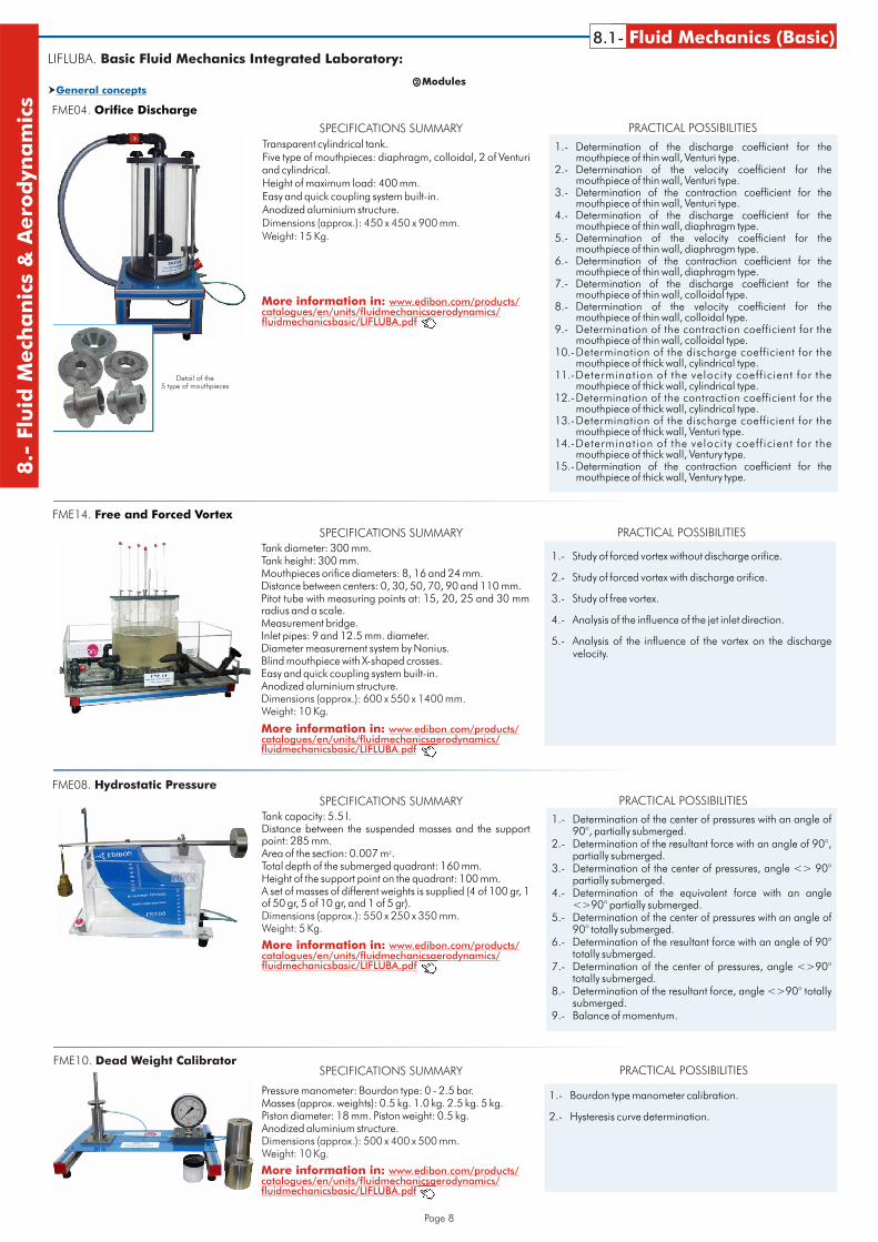
Transparent cylindrical tank.Five type of mouthpieces: diaphragm, colloidal, 2 of Venturiand cylindrical.Height of maximum load: 400 mm.Easy and quick coupling system built-in.Anodized aluminium structure.Dimensions (approx.): 450 x 450 x 900 mm. Weight: 15 Kg.
FME04. Orifice Discharge
1.- Determination of the discharge coefficient for the mouthpiece of thin wall, Venturi type.
2.- Determination of the velocity coefficient for the mouthpiece of thin wall, Venturi type.
3.- Determination of the contraction coefficient for the mouthpiece of thin wall, Venturi type.
4.- Determination of the discharge coefficient for the mouthpiece of thin wall, diaphragm type.
5.- Determination of the velocity coefficient for the mouthpiece of thin wall, diaphragm type.
6.- Determination of the contraction coefficient for the mouthpiece of thin wall, diaphragm type.
7.- Determination of the discharge coefficient for the mouthpiece of thin wall, colloidal type.
8.- Determination of the velocity coefficient for the mouthpiece of thin wall, colloidal type.
9.- Determination of the contraction coefficient for the mouthpiece of thin wall, colloidal type.
10.-Determination of the discharge coefficient for the mouthpiece of thick wall, cylindrical type.
11.-Determination of the veloci ty coeff ic ient for the mouthpiece of thick wall, cylindrical type.
12.-Determination of the contraction coefficient for the mouthpiece of thick wall, cylindrical type.
13.-Determination of the discharge coefficient for the mouthpiece of thick wall, Venturi type.
14.-Determination of the veloci ty coeff ic ient for the mouthpiece of thick wall, Ventury type.
15.-Determination of the contraction coefficient for the mouthpiece of thick wall, Ventury type.
SPECIFICATIONS SUMMARY PRACTICAL POSSIBILITIES
More information in: www.edibon.com/products/catalogues/en/units/fluidmechanicsaerodynamics/fluidmechanicsbasic/LIFLUBA.pdf
Tank diameter: 300 mm.Tank height: 300 mm.Mouthpieces orifice diameters: 8, 16 and 24 mm.Distance between centers: 0, 30, 50, 70, 90 and 110 mm.Pitot tube with measuring points at: 15, 20, 25 and 30 mm radius and a scale.Measurement bridge.Inlet pipes: 9 and 12.5 mm. diameter.Diameter measurement system by Nonius.Blind mouthpiece with X-shaped crosses.Easy and quick coupling system built-in.Anodized aluminium structure.Dimensions (approx.): 600 x 550 x 1400 mm.Weight: 10 Kg.
FME14. Free and Forced Vortex
1.- Study of forced vortex without discharge orifice.
2.- Study of forced vortex with discharge orifice.
3.- Study of free vortex.
4.- Analysis of the influence of the jet inlet direction.
5.- Analysis of the influence of the vortex on the discharge velocity.
SPECIFICATIONS SUMMARY PRACTICAL POSSIBILITIES
More information in: www.edibon.com/products/catalogues/en/units/fluidmechanicsaerodynamics/fluidmechanicsbasic/LIFLUBA.pdf
Tank capacity: 5.5 l.Distance between the suspended masses and the support point: 285 mm.
²Area of the section: 0.007 m .Total depth of the submerged quadrant: 160 mm.Height of the support point on the quadrant: 100 mm.A set of masses of different weights is supplied (4 of 100 gr, 1 of 50 gr, 5 of 10 gr, and 1 of 5 gr).Dimensions (approx.): 550 x 250 x 350 mm.Weight: 5 Kg.
FME08. Hydrostatic Pressure
1.- Determination of the center of pressures with an angle of 90°, partially submerged.
2.- Determination of the resultant force with an angle of 90°, partially submerged.
3.- Determination of the center of pressures, angle <> 90° partially submerged.
4.- Determination of the equivalent force with an angle <>90° partially submerged.
5.- Determination of the center of pressures with an angle of 90° totally submerged.
6.- Determination of the resultant force with an angle of 90° totally submerged.
7.- Determination of the center of pressures, angle <>90° totally submerged.
8.- Determination of the resultant force, angle <>90° totally submerged.
9.- Balance of momentum.
SPECIFICATIONS SUMMARY PRACTICAL POSSIBILITIES
More information in: www.edibon.com/products/catalogues/en/units/fluidmechanicsaerodynamics/fluidmechanicsbasic/LIFLUBA.pdf
Pressure manometer: Bourdon type: 0 - 2.5 bar.Masses (approx. weights): 0.5 kg. 1.0 kg. 2.5 kg. 5 kg.Piston diameter: 18 mm. Piston weight: 0.5 kg.Anodized aluminium structure. Dimensions (approx.): 500 x 400 x 500 mm. Weight: 10 Kg.
FME10. Dead Weight Calibrator
1.- Bourdon type manometer calibration.
2.- Hysteresis curve determination.
SPECIFICATIONS SUMMARY PRACTICAL POSSIBILITIES
More information in: www.edibon.com/products/catalogues/en/units/fluidmechanicsaerodynamics/fluidmechanicsbasic/LIFLUBA.pdf
Detail of the 5 type of mouthpieces
LIFLUBA. Basic Fluid Mechanics Integrated Laboratory:
Page 9 www.edibon.com
8.1- Fluid Mechanics (Basic)
8.-
Flu
idM
ech
an
ics
&A
ero
dyn
am
icsGeneral concepts�
Modules2
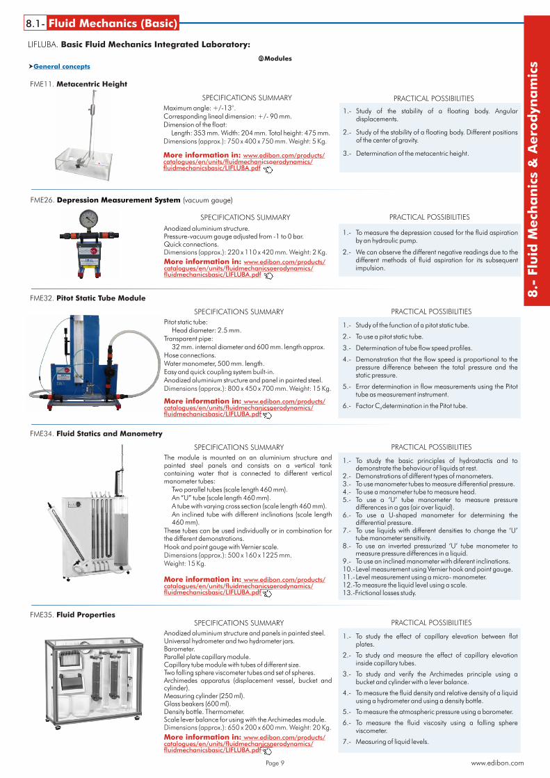
Maximum angle: +/-13°.Corresponding lineal dimension: +/- 90 mm.Dimension of the float:
Length: 353 mm. Width: 204 mm. Total height: 475 mm.Dimensions (approx.): 750 x 400 x 750 mm. Weight: 5 Kg.
FME11. Metacentric Height
1.- Study of the stability of a floating body. Angular displacements.
2.- Study of the stability of a floating body. Different positions of the center of gravity.
3.- Determination of the metacentric height.
SPECIFICATIONS SUMMARY PRACTICAL POSSIBILITIES
More information in: www.edibon.com/products/catalogues/en/units/fluidmechanicsaerodynamics/fluidmechanicsbasic/LIFLUBA.pdf
Anodized aluminium structure.Pressure-vacuum gauge adjusted from -1 to 0 bar.Quick connections.Dimensions (approx.): 220 x 110 x 420 mm. Weight: 2 Kg.
FME26. Depression Measurement System (vacuum gauge)
1.- To measure the depression caused for the fluid aspiration by an hydraulic pump.
2.- We can observe the different negative readings due to the different methods of fluid aspiration for its subsequent impulsion.
SPECIFICATIONS SUMMARY PRACTICAL POSSIBILITIES
More information in: www.edibon.com/products/catalogues/en/units/fluidmechanicsaerodynamics/fluidmechanicsbasic/LIFLUBA.pdf
Pitot static tube:Head diameter: 2.5 mm.
Transparent pipe:32 mm. internal diameter and 600 mm. length approx.
Hose connections.Water manometer, 500 mm. length.Easy and quick coupling system built-in.Anodized aluminium structure and panel in painted steel.Dimensions (approx.): 800 x 450 x 700 mm. Weight: 15 Kg.
FME32. Pitot Static Tube Module
1.- Study of the function of a pitot static tube.
2.- To use a pitot static tube.
3.- Determination of tube flow speed profiles.
4.- Demonstration that the flow speed is proportional to the pressure difference between the total pressure and the static pressure.
5.- Error determination in flow measurements using the Pitottube as measurement instrument.
6.- Factor C determination in the Pitot tube.d
SPECIFICATIONS SUMMARY PRACTICAL POSSIBILITIES
More information in: www.edibon.com/products/catalogues/en/units/fluidmechanicsaerodynamics/fluidmechanicsbasic/LIFLUBA.pdf
The module is mounted on an aluminium structure and painted steel panels and consists on a vertical tank containing water that is connected to different vertical manometer tubes:
Two parallel tubes (scale length 460 mm).An “U” tube (scale length 460 mm).A tube with varying cross section (scale length 460 mm).An inclined tube with different inclinations (scale length 460 mm).
These tubes can be used individually or in combination for the different demonstrations.Hook and point gauge with Vernier scale.Dimensions (approx.): 500 x 160 x 1225 mm.Weight: 15 Kg.
FME34. Fluid Statics and Manometry
1.- To study the basic principles of hydrostactis and to demonstrate the behaviour of liquids at rest.
2.- Demonstrations of different types of manometers.3.- To use manometer tubes to measure differential pressure.4.- To use a manometer tube to measure head.5.- To use a ‘U’ tube manometer to measure pressure
differences in a gas (air over liquid).6.- To use a U-shaped manometer for determining the
differential pressure.7.- To use liquids with different densities to change the ‘U’
tube manometer sensitivity.8.- To use an inverted pressurized ‘U’ tube manometer to
measure pressure differences in a liquid.9.- To use an inclined manometer with diferent inclinations.10.-Level measurement using Vernier hook and point gauge.11.-Level measurement using a micro- manometer.12.-To measure the liquid level using a scale.13.-Frictional losses study.
SPECIFICATIONS SUMMARY PRACTICAL POSSIBILITIES
More information in: www.edibon.com/products/catalogues/en/units/fluidmechanicsaerodynamics/fluidmechanicsbasic/LIFLUBA.pdf
Anodized aluminium structure and panels in painted steel.Universal hydrometer and two hydrometer jars.Barometer.Parallel plate capillary module.Capillary tube module with tubes of different size.Two falling sphere viscometer tubes and set of spheres.Archimedes apparatus (displacement vessel, bucket and cylinder).Measuring cylinder (250 ml).Glass beakers (600 ml).Density bottle. Thermometer.Scale lever balance for using with the Archimedes module.Dimensions (approx.): 650 x 200 x 600 mm. Weight: 20 Kg.
FME35. Fluid Properties
1.- To study the effect of capillary elevation between flat plates.
2.- To study and measure the effect of capillary elevation inside capillary tubes.
3.- To study and verify the Archimedes principle using a bucket and cylinder with a lever balance.
4.- To measure the fluid density and relative density of a liquid using a hydrometer and using a density bottle.
5.- To measure the atmospheric pressure using a barometer.
6.- To measure the fluid viscosity using a falling sphere viscometer.
7.- Measuring of liquid levels.
SPECIFICATIONS SUMMARY PRACTICAL POSSIBILITIES
More information in: www.edibon.com/products/catalogues/en/units/fluidmechanicsaerodynamics/fluidmechanicsbasic/LIFLUBA.pdf
Laws�
Manometer range: 0 to 300 mm of water.Number of manometer tubes: 8Upstream diameter of the throat: 25 mm.Narrowing:
Downstream: 21°. Upstream: 10°.Easy and quick coupling system built-in.Anodized aluminium structure and panel in painted steel.Dimensions (approx.): 800 x 450 x 700 mm. Weight: 15 Kg.
FME03. Bernoulli’s Theorem Demonstration
1.- Determination of the exact section in Venturi’s tube.
2.- Demonstration of Bernoulli’s Theorem. Divergent-convergent position.
3.- Determination of Bernoulli’s Theorem equation. Convergent-divergent position.
4.- Observation of differences between convergent and divergent position.
SPECIFICATIONS SUMMARY PRACTICAL POSSIBILITIES
More information in: www.edibon.com/products/catalogues/en/units/fluidmechanicsaerodynamics/fluidmechanicsbasic/LIFLUBA.pdf
Manometer (Bourdon type), range: 0-2.5 bar.Manometer (Bourdon type), range: 0-(-1) bar.2 tanks, height: 135 mm and internal diameter: 64 mm.Venturi tube with 6 tappings (Divergent/Convergent).Differential manometers: 0-500 mm.5 Manometric tubes.Easy and quick coupling system built-in.Anodized aluminium structure and panel in painted steel.Dimensions (approx.): 750 x 400 x 850 mm. Weight: 10 Kg.
FME22. Venturi, Bernoulli and Cavitation Unit
1.- How to fill the manometric tubes.
2.- Flow calculation.
3.- Determination of the exact section in Venturi’s tube. Bernoulli’s theorem study.
4.- Cavitation study.
5.- Pressure reduction in a tank.
6.- Aspiration pump.
7.- Aspiration pump for mixing two liquids.
8.- Using for air and water mixing.
SPECIFICATIONS SUMMARY PRACTICAL POSSIBILITIES
More information in: www.edibon.com/products/catalogues/en/units/fluidmechanicsaerodynamics/fluidmechanicsbasic/LIFLUBA.pdf
Page 10
8.1- Fluid Mechanics (Basic)8.-
Flu
idM
ech
an
ics
&A
ero
dyn
am
ics
LIFLUBA. Basic Fluid Mechanics Integrated Laboratory:Modules2
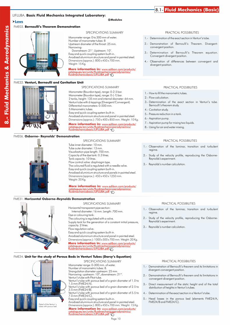
Tube inner diameter: 10 mm. Tube outer diameter: 13 mm.Visualization pipe length: 700 mm.Capacity of the dye tank: 0.3 litres.Tank capacity: 10 litres.Flow control valve: diaphragm type.The coloured fluid is regulated with a needle valve.Easy and quick coupling system built-in.Anodized aluminium structure and panels in painted steel.Dimensions (approx.): 450 x 450 x 1250 mm.Weight: 20 Kg.
FME06. Osborne- Reynolds’ Demonstration
1.- Observation of the laminar, transition and turbulent regime.
2.- Study of the velocity profile, reproducing the Osborne-Reynolds’s experiment.
3.- Reynolds’s number calculation.
SPECIFICATIONS SUMMARY PRACTICAL POSSIBILITIES
More information in: www.edibon.com/products/catalogues/en/units/fluidmechanicsaerodynamics/fluidmechanicsbasic/LIFLUBA.pdf
Horizontal transparent pipe section:
Internal diameter: 16 mm. Length: 700 mm.
Dye or colouring tank.
The colouring is regulated with a valve.
Supply tank for the generation of a constant initial pressure, capacity: 2 litres.
Flow regulation valve.
Easy and quick coupling system built-in.
Anodized aluminium structure and panel in painted steel.
Dimensions (approx.): 1000 x 500 x 700 mm. Weight: 20 Kg.
FME31. Horizontal Osborne-Reynolds Demonstration
1.- Observation of the laminar, transition and turbulent regime.
2.- Study of the velocity profile, reproducing the Osborne-Reynolds’s experiment.
3.- Reynolds’s number calculation.
SPECIFICATIONS SUMMARY PRACTICAL POSSIBILITIES
More information in: www.edibon.com/products/catalogues/en/units/fluidmechanicsaerodynamics/fluidmechanicsbasic/LIFLUBA.pdf
Manometer range: 0-300 mm. of water.Number of manometric tubes: 8.Strangulation diameter upstream: 25 mm.Narrowing: upstream: 10º, downstream: 21º.Venturi’s tube with Pitot tube.Venturi’s tube with porous bed of a grain diameter of 1.0 to 1.5 mm (FME24/A).Venturi’s tube with porous bed of a grain diameter of 2.5 to 3.5 mm (FME24/B).Venturi’s tube with porous bed of a grain diameter of 5.5 to 7.0 mm (FME24/C).Easy and quick coupling system built-in.Anodized aluminium structure and panel in painted steel.Dimensions (approx.): 800 x 450 x 700 mm. Weight: 15 Kg.
FME24. Unit for the study of Porous Beds in Venturi Tubes (Darcy’s Equation)
1.- Demonstration of Bernoulli’s theorem and its limitations in divergent-convergent position.
2.- Demonstration of Bernoulli’s theorem and its limitations in convergent-divergent position.
3.- Direct measurement of the static height and of the total distribution of heights in Venturi’s tubes.
4.- Determination of the exact section in a Venturi’s tube.
5.- Head losses in the porous bed (elements FME24/A, FME24/B and FME24/C).
SPECIFICATIONS SUMMARY PRACTICAL POSSIBILITIES
More information in: www.edibon.com/products/catalogues/en/units/fluidmechanicsaerodynamics/fluidmechanicsbasic/LIFLUBA.pdf
Detail of the Venturi´stubes with porous bed
Laws�
Demonstration�
Capacity of the dye tank: 0.3 litres.Width/length of the channel approx.: 15/630 mm.Depth of channel approx.: 150 mm.Damping tank that eliminates the turbulences.Hydrodynamic models: 2 lengthened, 2 circular of 25 and 50 mm. dia., rectangle with rounded edges and wedge.Easy and quick coupling system built-in.Anodized aluminium structure.Dimensions (approx.): 900 x 450 x 500 mm. Weight: 7 Kg.
FME09. Flow Visualization in Channels
1.- Leakage of liquids by thin-wall weirs.
2.- Liquid leakage by thick-wall weirs.
3.- Models with wing profile submerged in a fluid current.
4.- Circular models submerged in a fluid current.
5.- Demonstration of the phenomenon associated to the flow in open channels.
6.- Visualization of the flow lines around different submerged hydrodynamic models.
SPECIFICATIONS SUMMARY PRACTICAL POSSIBILITIES
More information in: www.edibon.com/products/catalogues/en/units/fluidmechanicsaerodynamics/fluidmechanicsbasic/LIFLUBA.pdf
Capacity of dye tank: 0.3 litres.Width/length of the table: 400/210 mm.Depth of the table: adjustable depending on the models.Hydrodynamic models:
Two circular ones of 25 and 50 mm. diameter.Two rectangular ones of 25 x 25 and 50 x 50 mm.Wedge.
Easy and quick coupling system built-in.Anodized aluminium structure.Dimensions (approx.): 870 x 450 x 400 mm. Weight: 10 Kg.
FME20. Laminar Flow Demonstration
1.- Ideal flow around a submerged cylinder.
2.- Ideal flow around a submerged profile.
3.- Ideal flow around a body in peak.
4.- Ideal flow in a convergent channel.
5.- Ideal flow in a divergent channel.
6.- Ideal flow in an elbow of 90º.
7.- Ideal flow in a sudden contraction.
8.- Ideal flow in a sudden broadening.
9.- Substitution of a line of current for a solid edge.
SPECIFICATIONS SUMMARY PRACTICAL POSSIBILITIES
More information in: www.edibon.com/products/catalogues/en/units/fluidmechanicsaerodynamics/fluidmechanicsbasic/LIFLUBA.pdf
LIFLUBA. Basic Fluid Mechanics Integrated Laboratory:
Page 11 www.edibon.com
8.1- Fluid Mechanics (Basic)
8.-
Flu
idM
ech
an
ics
&A
ero
dyn
am
ics
Modules2
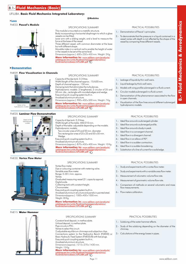
This module is mounted on a metallic structure.Body incorporating a horizontal diaphragm to which a glass vessels can be fitted.Lever arm with a sliding weight, and a level to measure the force at the base of the vessel. Three different vessel, with common diammeter at the base but with different shape.Movable index in a vertical rod to enable the height of water in the vessels to be set at the same level.Dimensions (approx.): 600 x 250 x 450 mm. Weight: 3 Kg.
FME33. Pascal’s Module
1.- Demonstration of Pascal´s principles.
2.- To demonstrate that the pressure in a liquid contained in a vessel varies with depth is not affected by the shape of the vessel by comparing three different vessels.
SPECIFICATIONS SUMMARY PRACTICAL POSSIBILITIES
More information in: www.edibon.com/products/catalogues/en/units/fluidmechanicsaerodynamics/fluidmechanicsbasic/LIFLUBA.pdf
Vortex flow meter.Dye or colouring container with metering valve. Variable area flow meter.Range: 0-30 l./min. approx.Valves.Graduated measuring vessel (2 l. capacity approx).Digital scale. Collecting tank with constant height.Chronometer.Easy and quick coupling system built-in.Anodized aluminium structure and panels in painted steel.Dimensions(approx.): 1000 x 400 x 1000 mm.Weight: 30 Kg.
FME30. Vortex Flow Meter
1.- Study and experiments with a vortex flow meter.
2.- Study and experiments with a variable area flow meter.
3.- Measurement of volumetric volume flow rate.
4.- Measurement of gravimetric volume flow rate.
5.- Comparison of methods on several volumetric and mass flow measurements.
6.- Flow meters calibration.
SPECIFICATIONS SUMMARY PRACTICAL POSSIBILITIES
More information in: www.edibon.com/products/catalogues/en/units/fluidmechanicsaerodynamics/fluidmechanicsbasic/LIFLUBA.pdf
Constant level deposit, in methacrylate.Unload deposit, in methacrylate.Pipe circuits in PVC.Valves to select the circuit.2 adjustable equilibrium chimneys and subjection clips.Connections system to the Hydraulics Bench (FME00) or Basic Hydraulic Feed System (FME00/B) with fast plugs.Easy and quick coupling system built-in.Anodized aluminium structure.Dimensions (approx).:1215 x 270 x 1430 mm. Weight: 15 Kg.
FME15. Water Hammer
1.- Subduing of the water hammer effects.
2.- Study of the subduing depending on the diameter of the chimney.
3.- Calculations of the energy losses in pipes.
SPECIFICATIONS SUMMARY PRACTICAL POSSIBILITIES
More information in: www.edibon.com/products/catalogues/en/units/fluidmechanicsaerodynamics/fluidmechanicsbasic/LIFLUBA.pdf
Detail of thehydrodynamic models
Detail of the hydrodynamic
models
Page 12
Demonstration�
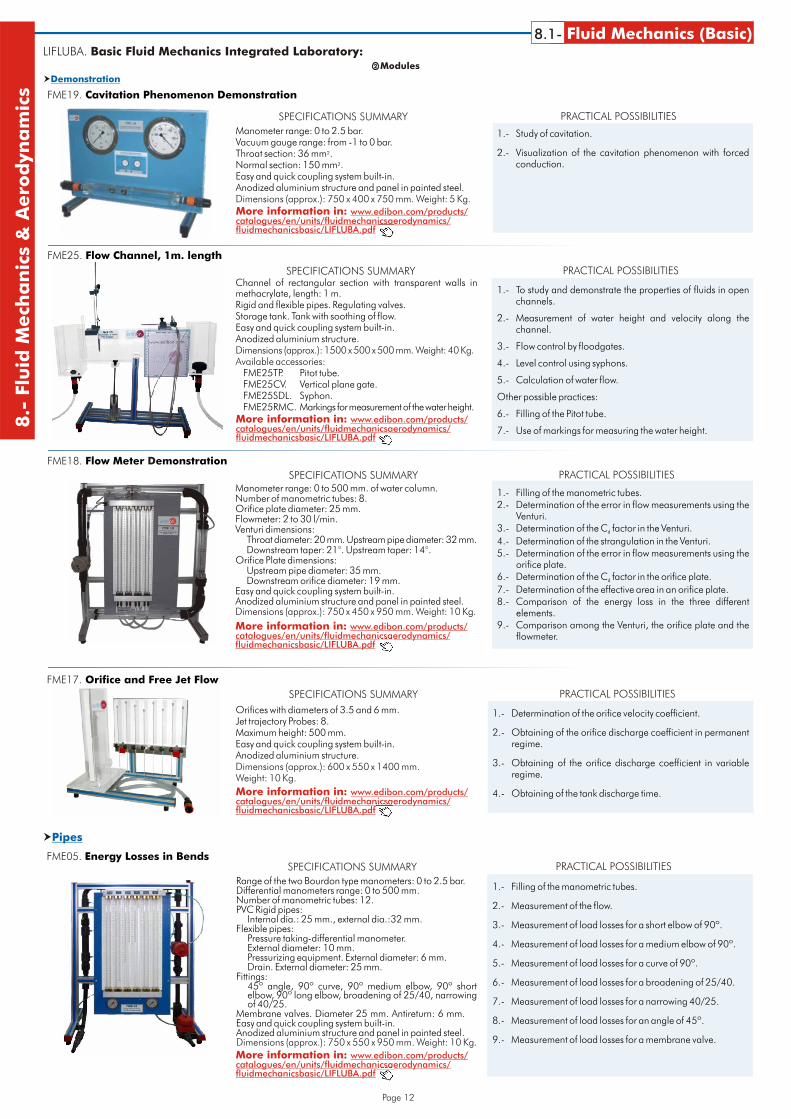
Manometer range: 0 to 2.5 bar.Vacuum gauge range: from -1 to 0 bar.Throat section: 36 mm².Normal section: 150 mm².Easy and quick coupling system built-in.Anodized aluminium structure and panel in painted steel.Dimensions (approx.): 750 x 400 x 750 mm. Weight: 5 Kg.
FME19. Cavitation Phenomenon Demonstration
1.- Study of cavitation.
2.- Visualization of the cavitation phenomenon with forced conduction.
SPECIFICATIONS SUMMARY PRACTICAL POSSIBILITIES
More information in: www.edibon.com/products/catalogues/en/units/fluidmechanicsaerodynamics/fluidmechanicsbasic/LIFLUBA.pdf
Channel of rectangular section with transparent walls in methacrylate, length: 1 m.Rigid and flexible pipes. Regulating valves.Storage tank. Tank with soothing of flow.Easy and quick coupling system built-in.Anodized aluminium structure.
FME25TP. Pitot tube.FME25CV. Vertical plane gate.FME25SDL. Syphon.FME25RMC. Markings for measurement of the water height.
Dimensions (approx.): 1500 x 500 x 500 mm. Weight: 40 Kg.Available accessories:
FME25. Flow Channel, 1m. length
1.- To study and demonstrate the properties of fluids in open channels.
2.- Measurement of water height and velocity along the channel.
3.- Flow control by floodgates.
4.- Level control using syphons.
5.- Calculation of water flow.
Other possible practices:
6.- Filling of the Pitot tube.
7.- Use of markings for measuring the water height.
SPECIFICATIONS SUMMARY PRACTICAL POSSIBILITIES
More information in: www.edibon.com/products/catalogues/en/units/fluidmechanicsaerodynamics/fluidmechanicsbasic/LIFLUBA.pdf
Manometer range: 0 to 500 mm. of water column.Number of manometric tubes: 8.Orifice plate diameter: 25 mm.Flowmeter: 2 to 30 l/min.Venturi dimensions:
Throat diameter: 20 mm. Upstream pipe diameter: 32 mm.Downstream taper: 21°. Upstream taper: 14°.
Orifice Plate dimensions:Upstream pipe diameter: 35 mm.Downstream orifice diameter: 19 mm.
Easy and quick coupling system built-in.Anodized aluminium structure and panel in painted steel.Dimensions (approx.): 750 x 450 x 950 mm. Weight: 10 Kg.
FME18. DFlow Meter emonstration
1.- Filling of the manometric tubes.2.- Determination of the error in flow measurements using the
Venturi.3.- Determination of the C factor in the Venturi.d
4.- Determination of the strangulation in the Venturi.5.- Determination of the error in flow measurements using the
orifice plate.6.- Determination of the C factor in the orifice plate.d
7.- Determination of the effective area in an orifice plate.8.- Comparison of the energy loss in the three different
elements.9.- Comparison among the Venturi, the orifice plate and the
flowmeter.
SPECIFICATIONS SUMMARY PRACTICAL POSSIBILITIES
More information in: www.edibon.com/products/catalogues/en/units/fluidmechanicsaerodynamics/fluidmechanicsbasic/LIFLUBA.pdf
8.1- Fluid Mechanics (Basic)8.-
Flu
idM
ech
an
ics
&A
ero
dyn
am
ics
LIFLUBA. Basic Fluid Mechanics Integrated Laboratory:Modules2
Orifices with diameters of 3.5 and 6 mm.Jet trajectory Probes: 8.Maximum height: 500 mm.Easy and quick coupling system built-in.Anodized aluminium structure.Dimensions (approx.): 600 x 550 x 1400 mm.Weight: 10 Kg.
FME17. Orifice and Free Jet Flow
1.- Determination of the orifice velocity coefficient.
2.- Obtaining of the orifice discharge coefficient in permanent regime.
3.- Obtaining of the orifice discharge coefficient in variable regime.
4.- Obtaining of the tank discharge time.
SPECIFICATIONS SUMMARY PRACTICAL POSSIBILITIES
More information in: www.edibon.com/products/catalogues/en/units/fluidmechanicsaerodynamics/fluidmechanicsbasic/LIFLUBA.pdf
Pipes�
Range of the two Bourdon type manometers: 0 to 2.5 bar.Differential manometers range: 0 to 500 mm.Number of manometric tubes: 12.PVC Rigid pipes:
Internal dia.: 25 mm., external dia.:32 mm.Flexible pipes:
Pressure taking-differential manometer.External diameter: 10 mm.Pressurizing equipment. External diameter: 6 mm.Drain. External diameter: 25 mm.
Fittings:45º angle, 90º curve, 90º medium elbow, 90º short elbow, 90º long elbow, broadening of 25/40, narrowing of 40/25.
Membrane valves. Diameter 25 mm. Antireturn: 6 mm.Easy and quick coupling system built-in.Anodized aluminium structure and panel in painted steel.Dimensions (approx.): 750 x 550 x 950 mm. Weight: 10 Kg.
FME05. Energy Losses in Bends
1.- Filling of the manometric tubes.
2.- Measurement of the flow.
3.- Measurement of load losses for a short elbow of 90º.
4.- Measurement of load losses for a medium elbow of 90º.
5.- Measurement of load losses for a curve of 90º.
6.- Measurement of load losses for a broadening of 25/40.
7.- Measurement of load losses for a narrowing 40/25.
8.- Measurement of load losses for an angle of 45º.
9.- Measurement of load losses for a membrane valve.
SPECIFICATIONS SUMMARY PRACTICAL POSSIBILITIES
More information in: www.edibon.com/products/catalogues/en/units/fluidmechanicsaerodynamics/fluidmechanicsbasic/LIFLUBA.pdf
Page 13
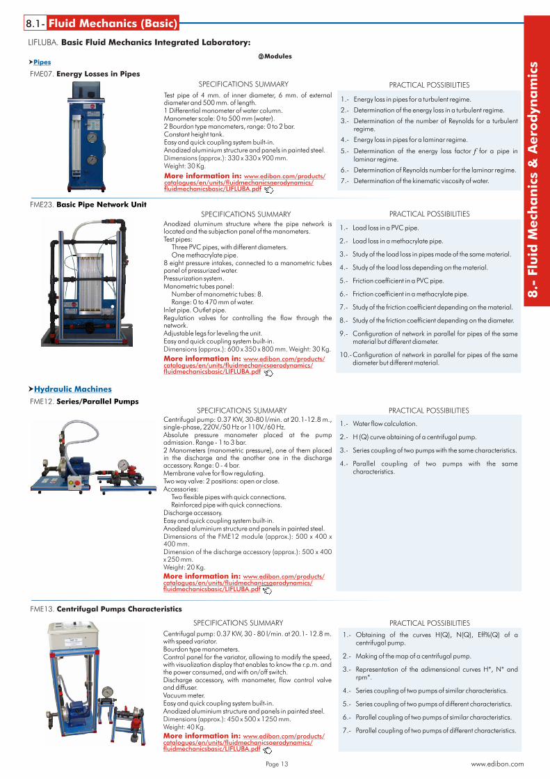
Test pipe of 4 mm. of inner diameter, 6 mm. of external diameter and 500 mm. of length.1 Differential manometer of water column.Manometer scale: 0 to 500 mm (water).2 Bourdon type manometers, range: 0 to 2 bar.Constant height tank.Easy and quick coupling system built-in.Anodized aluminium structure and panels in painted steel.Dimensions (approx.): 330 x 330 x 900 mm. Weight: 30 Kg.
FME07. Energy Losses in Pipes
1.- Energy loss in pipes for a turbulent regime.
2.- Determination of the energy loss in a turbulent regime.
3.- Determination of the number of Reynolds for a turbulent regime.
4.- Energy loss in pipes for a laminar regime.
5.- Determination of the energy loss factor f for a pipe in laminar regime.
6.- Determination of Reynolds number for the laminar regime.
7.- Determination of the kinematic viscosity of water.
SPECIFICATIONS SUMMARY PRACTICAL POSSIBILITIES
More information in: www.edibon.com/products/catalogues/en/units/fluidmechanicsaerodynamics/fluidmechanicsbasic/LIFLUBA.pdf
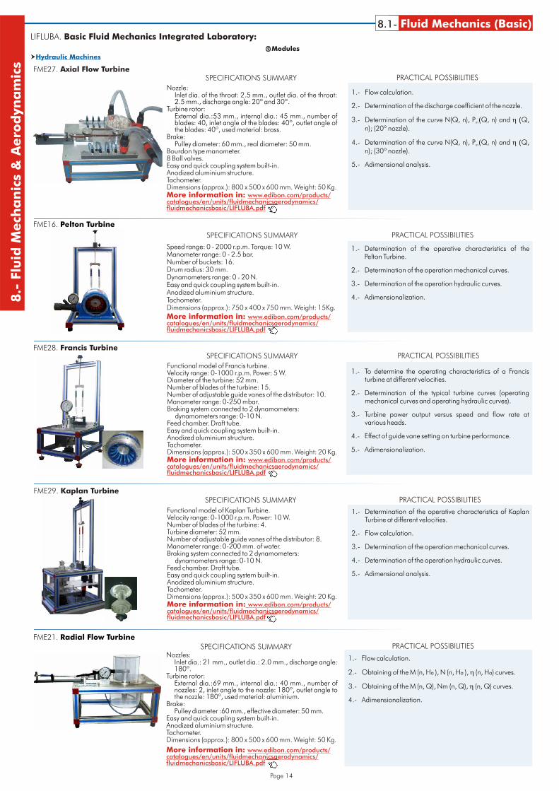
Anodized aluminum structure where the pipe network is located and the subjection panel of the manometers.Test pipes:
Three PVC pipes, with different diameters.One methacrylate pipe.
8 eight pressure intakes, connected to a manometric tubes panel of pressurized water.Pressurization system.Manometric tubes panel:
Number of manometric tubes: 8.Range: 0 to 470 mm of water.
Inlet pipe. Outlet pipe.Regulation valves for controlling the flow through the network.Adjustable legs for leveling the unit.Easy and quick coupling system built-in.Dimensions (approx.): 600 x 350 x 800 mm. Weight: 30 Kg.
1.- Load loss in a PVC pipe.
2.- Load loss in a methacrylate pipe.
3.- Study of the load loss in pipes made of the same material.
4.- Study of the load loss depending on the material.
5.- Friction coefficient in a PVC pipe.
6.- Friction coefficient in a methacrylate pipe.
7.- Study of the friction coefficient depending on the material.
8.- Study of the friction coefficient depending on the diameter.
9.- Configuration of network in parallel for pipes of the same material but different diameter.
10.-Configuration of network in parallel for pipes of the same diameter but different material.
SPECIFICATIONS SUMMARY PRACTICAL POSSIBILITIES
More information in: www.edibon.com/products/catalogues/en/units/fluidmechanicsaerodynamics/fluidmechanicsbasic/LIFLUBA.pdf
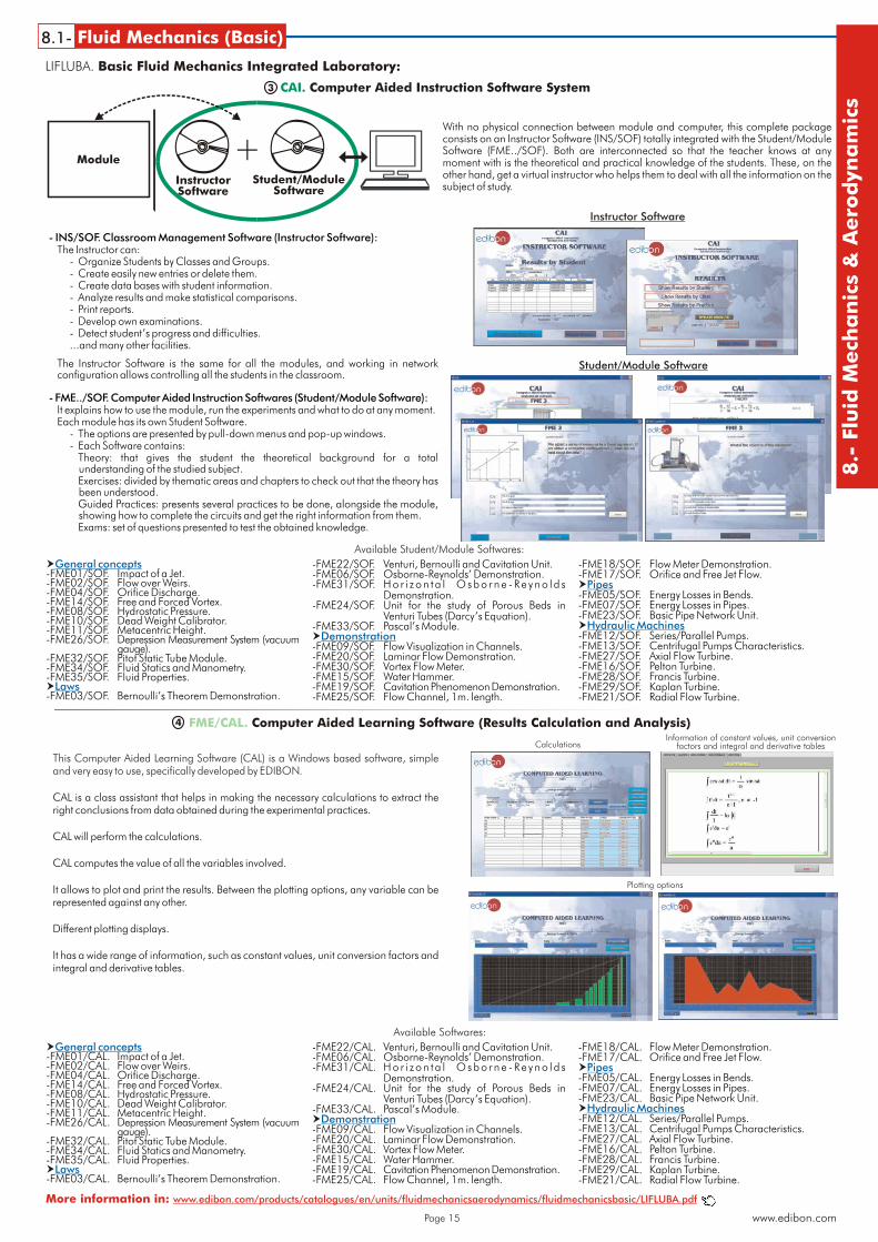
Centrifugal pump: 0.37 KW, 30-80 l/min. at 20.1-12.8 m., single-phase, 220V./50 Hz or 110V./60 Hz.Absolute pressure manometer placed at the pump admission. Range - 1 to 3 bar.2 Manometers (manometric pressure), one of them placed in the discharge and the another one in the discharge accessory. Range: 0 - 4 bar.Membrane valve for flow regulating.Two way valve: 2 positions: open or close.Accessories:
Two flexible pipes with quick connections.Reinforced pipe with quick connections.
Discharge accessory.Easy and quick coupling system built-in.Anodized aluminium structure and panels in painted steel.Dimensions of the FME12 module (approx.): 500 x 400 x 400 mm.Dimension of the discharge accessory (approx.): 500 x 400 x 250 mm.Weight: 20 Kg.
FME12. Series/Parallel Pumps
1.- Water flow calculation.
2.- H (Q) curve obtaining of a centrifugal pump.
3.- Series coupling of two pumps with the same characteristics.
4.- Parallel coupling of two pumps with the same characteristics.
SPECIFICATIONS SUMMARY PRACTICAL POSSIBILITIES
More information in: www.edibon.com/products/catalogues/en/units/fluidmechanicsaerodynamics/fluidmechanicsbasic/LIFLUBA.pdf
Hydraulic Machines�
LIFLUBA. Basic Fluid Mechanics Integrated Laboratory:
www.edibon.com
8.1- Fluid Mechanics (Basic)
8.-
Flu
idM
ech
an
ics
&A
ero
dyn
am
ics
Modules2
Pipes�
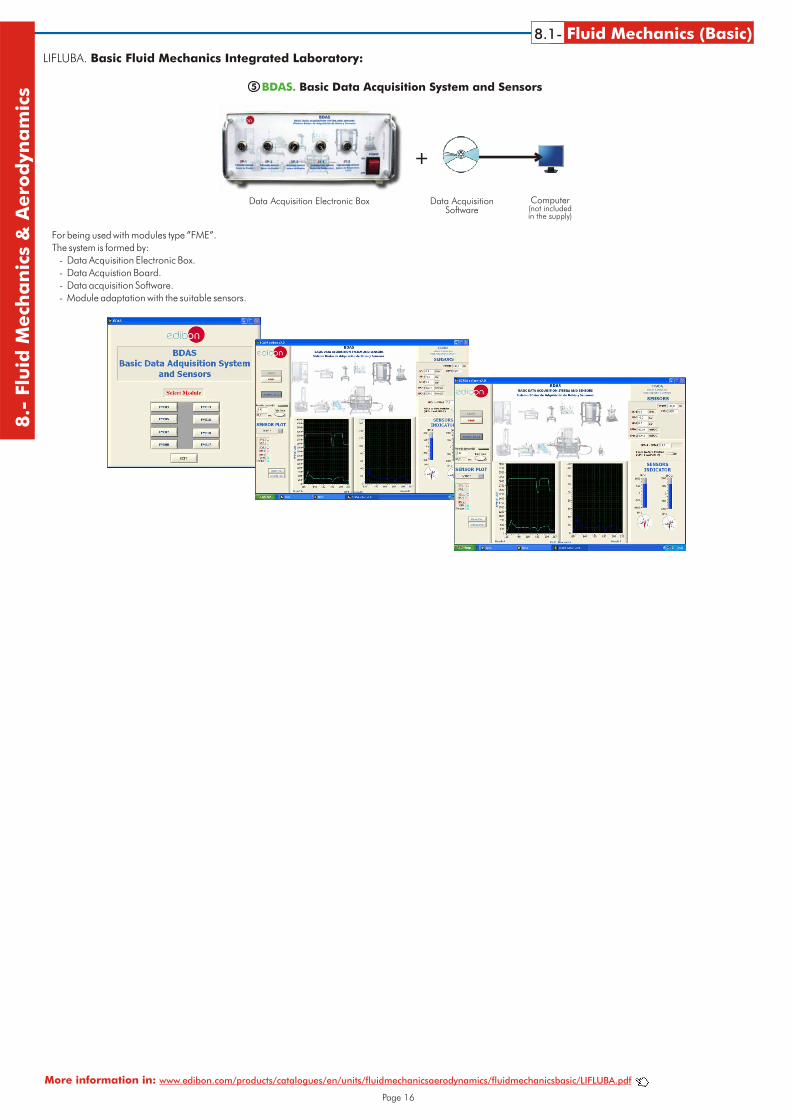
Centrifugal pump: 0.37 KW, 30 - 80 l/min. at 20.1- 12.8 m. with speed variator.Bourdon type manometers.Control panel for the variator, allowing to modify the speed, with visualization display that enables to know the r.p.m. and the power consumed, and with on/off switch.Discharge accessory, with manometer, flow control valve and diffuser.Vacuum meter.Easy and quick coupling system built-in.Anodized aluminium structure and panels in painted steel.Dimensions (approx.): 450 x 500 x 1250 mm.Weight: 40 Kg.
FME13. Centrifugal Pumps Characteristics
1.- Obtaining of the curves H(Q), N(Q), Eff%(Q) of a centrifugal pump.
2.- Making of the map of a centrifugal pump.
3.- Representation of the adimensional curves H*, N* and rpm*.
4.- Series coupling of two pumps of similar characteristics.
5.- Series coupling of two pumps of different characteristics.
6.- Parallel coupling of two pumps of similar characteristics.
7.- Parallel coupling of two pumps of different characteristics.
SPECIFICATIONS SUMMARY PRACTICAL POSSIBILITIES
More information in: www.edibon.com/products/catalogues/en/units/fluidmechanicsaerodynamics/fluidmechanicsbasic/LIFLUBA.pdf
FME23. Basic Pipe Network Unit
Page 14
Hydraulic Machines�
Speed range: 0 - 2000 r.p.m. Torque: 10 W.Manometer range: 0 - 2.5 bar.Number of buckets: 16. Drum radius: 30 mm.Dynamometers range: 0 - 20 N.Easy and quick coupling system built-in.Anodized aluminium structure.Tachometer.Dimensions (approx.): 750 x 400 x 750 mm. Weight: 15Kg.
FME16. Pelton Turbine
1.- Determination of the operative characteristics of the Pelton Turbine.
2.- Determination of the operation mechanical curves.
3.- Determination of the operation hydraulic curves.
4.- Adimensionalization.
SPECIFICATIONS SUMMARY PRACTICAL POSSIBILITIES
More information in: www.edibon.com/products/catalogues/en/units/fluidmechanicsaerodynamics/fluidmechanicsbasic/LIFLUBA.pdf
Functional model of Francis turbine.Velocity range: 0-1000 r.p.m. Power: 5 W.Diameter of the turbine: 52 mm.Number of blades of the turbine: 15.Number of adjustable guide vanes of the distributor: 10.Manometer range: 0-250 mbar.Braking system connected to 2 dynamometers:
dynamometers range: 0-10 N.Feed chamber. Draft tube.Easy and quick coupling system built-in.Anodized aluminium structure.Tachometer.Dimensions (approx.): 500 x 350 x 600 mm. Weight: 20 Kg.
FME28. Francis Turbine
1.- To determine the operating characteristics of a Francisturbine at different velocities.
2.- Determination of the typical turbine curves (operating mechanical curves and operating hydraulic curves).
3.- Turbine power output versus speed and flow rate at various heads.
4.- Effect of guide vane setting on turbine performance.
5.- Adimensionalization.
SPECIFICATIONS SUMMARY PRACTICAL POSSIBILITIES
More information in: www.edibon.com/products/catalogues/en/units/fluidmechanicsaerodynamics/fluidmechanicsbasic/LIFLUBA.pdf
Functional model of Kaplan Turbine.Velocity range: 0-1000 r.p.m. Power: 10 W.Number of blades of the turbine: 4.Turbine diameter: 52 mm.Number of adjustable guide vanes of the distributor: 8.Manometer range: 0-200 mm. of water.Braking system connected to 2 dynamometers:
dynamometers range: 0-10 N.Feed chamber. Draft tube.Easy and quick coupling system built-in.Anodized aluminium structure.Tachometer.Dimensions (approx.): 500 x 350 x 600 mm. Weight: 20 Kg.
FME29. Kaplan Turbine
1.- Determination of the operative characteristics of KaplanTurbine at different velocities.
2.- Flow calculation.
3.- Determination of the operation mechanical curves.
4.- Determination of the operation hydraulic curves.
5.- Adimensional analysis.
SPECIFICATIONS SUMMARY PRACTICAL POSSIBILITIES
More information in: www.edibon.com/products/catalogues/en/units/fluidmechanicsaerodynamics/fluidmechanicsbasic/LIFLUBA.pdf
8.1- Fluid Mechanics (Basic)8.-
Flu
idM
ech
an
ics
&A
ero
dyn
am
ics
LIFLUBA. Basic Fluid Mechanics Integrated Laboratory:
Modules2
Nozzle:Inlet dia. of the throat: 2.5 mm., outlet dia. of the throat: 2.5 mm., discharge angle: 20º and 30º.
Turbine rotor:External dia.:53 mm., internal dia.: 45 mm., number of blades: 40, inlet angle of the blades: 40º, outlet angle of the blades: 40º, used material: brass.
Brake:Pulley diameter: 60 mm., real diameter: 50 mm.
Bourdon type manometer.8 Ball valves.Easy and quick coupling system built-in.Anodized aluminium structure.Tachometer.Dimensions (approx.): 800 x 500 x 600 mm. Weight: 50 Kg.
FME27. Axial Flow Turbine
1.- Flow calculation.
2.- Determination of the discharge coefficient of the nozzle.
3.- Determination of the curve N(Q, n), P (Q, n) and ��(Q,m
n); (20º nozzle).
4.- Determination of the curve N(Q, n), P (Q, n) and ��(Q,m
n); (30º nozzle).
5.- Adimensional analysis.
SPECIFICATIONS SUMMARY PRACTICAL POSSIBILITIES
More information in: www.edibon.com/products/catalogues/en/units/fluidmechanicsaerodynamics/fluidmechanicsbasic/LIFLUBA.pdf
Nozzles:Inlet dia.: 21 mm., outlet dia.: 2.0 mm., discharge angle: 180º.
Turbine rotor:External dia.:69 mm., internal dia.: 40 mm., number of nozzles: 2, inlet angle to the nozzle: 180º, outlet angle to the nozzle: 180º, used material: aluminium.
Brake:Pulley diameter :60 mm., effective diameter: 50 mm.
Easy and quick coupling system built-in.Anodized aluminium structure.Tachometer.Dimensions (approx.): 800 x 500 x 600 mm. Weight: 50 Kg.
FME21. Radial Flow Turbine
1.- Flow calculation.
2.- Obtaining of the M (n, Ha ), N (n, Ha ), � (n, Ha) curves.
3.- Obtaining of the M (n, Q), Nm (n, Q), � (n, Q) curves.
4.- Adimensionalization.
SPECIFICATIONS SUMMARY PRACTICAL POSSIBILITIES
More information in: www.edibon.com/products/catalogues/en/units/fluidmechanicsaerodynamics/fluidmechanicsbasic/LIFLUBA.pdf
LIFLUBA. Basic Fluid Mechanics Integrated Laboratory:
Page 15 www.edibon.com
8.1- Fluid Mechanics (Basic)
8.-
Flu
idM
ech
an
ics
&A
ero
dyn
am
ics
With no physical connection between module and computer, this complete package consists on an Instructor Software (INS/SOF) totally integrated with the Student/Module Software (FME../SOF). Both are interconnected so that the teacher knows at any moment with is the theoretical and practical knowledge of the students. These, on the other hand, get a virtual instructor who helps them to deal with all the information on the subject of study.
InstructorSoftware
Module
Student/ModuleSoftware
+
CAI. Computer Aided Instruction Software System3
- FME../SOF. Computer Aided Instruction Softwares (Student/Module Software):It explains how to use the module, run the experiments and what to do at any moment. Each module has its own Student Software.
- The options are presented by pull-down menus and pop-up windows.- Each Software contains:
Theory: that gives the student the theoretical background for a total understanding of the studied subject.Exercises: divided by thematic areas and chapters to check out that the theory has been understood.Guided Practices: presents several practices to be done, alongside the module, showing how to complete the circuits and get the right information from them.Exams: set of questions presented to test the obtained knowledge.
- INS/SOF. Classroom Management Software (Instructor Software):The Instructor can:
- Organize Students by Classes and Groups.- Create easily new entries or delete them.- Create data bases with student information. - Analyze results and make statistical comparisons.- Print reports.- Develop own examinations.- Detect student’s progress and difficulties....and many other facilities.
The Instructor Software is the same for all the modules, and working in network configuration allows controlling all the students in the classroom.
Instructor Software
Student/Module Software
FME/CAL. Computer Aided Learning Software (Results Calculation and Analysis)4
Calculations
Plotting options
Information of constant values, unit conversionfactors and integral and derivative tables
This Computer Aided Learning Software (CAL) is a Windows based software, simple and very easy to use, specifically developed by EDIBON.
CAL is a class assistant that helps in making the necessary calculations to extract the right conclusions from data obtained during the experimental practices.
CAL will perform the calculations.
CAL computes the value of all the variables involved.
It allows to plot and print the results. Between the plotting options, any variable can be represented against any other.
Different plotting displays.
It has a wide range of information, such as constant values, unit conversion factors and integral and derivative tables.
�
�
�
�
�
General concepts
Pipes
Hydraulic MachinesDemonstration
Laws
-FME22/SOF. Venturi, Bernoulli and Cavitation Unit. -FME18/SOF. Flow Meter Demonstration.-FME01/SOF. Impact of a Jet. -FME17/SOF. Orifice and Free Jet Flow.-FME06/SOF. Osborne-Reynolds’ Demonstration.-FME02/SOF. Flow over Weirs. -FME31/SOF. H o r i z o n t a l O s b o r n e - Re y n o l d s-FME04/SOF. Orifice Discharge. Demonstration. -FME05/SOF. Energy Losses in Bends.-FME14/SOF. Free and Forced Vortex. -FME24/SOF. Unit for the study of Porous Beds in -FME07/SOF. Energy Losses in Pipes.-FME08/SOF. Hydrostatic Pressure. -FME23/SOF. Basic Pipe Network Unit.Venturi Tubes (Darcy’s Equation).-FME10/SOF. Dead Weight Calibrator.
-FME33/SOF. Pascal’s Module.-FME11/SOF. Metacentric Height.-FME12/SOF. Series/Parallel Pumps.-FME26/SOF. Depression Measurement System (vacuum -FME13/SOF. Centrifugal Pumps Characteristics.-FME09/SOF. Flow Visualization in Channels.gauge).
-FME20/SOF. Laminar Flow Demonstration. -FME27/SOF. Axial Flow Turbine.-FME32/SOF. Pitot Static Tube Module.-FME30/SOF. Vortex Flow Meter. -FME16/SOF. Pelton Turbine.-FME34/SOF. Fluid Statics and Manometry.
-FME28/SOF. Francis Turbine.-FME35/SOF. Fluid Properties. -FME15/SOF. Water Hammer.-FME29/SOF. Kaplan Turbine.-FME19/SOF. Cavitation Phenomenon Demonstration.
-FME03/SOF. Bernoulli’s Theorem Demonstration. -FME21/SOF. Radial Flow Turbine.-FME25/SOF. Flow Channel, 1m. length.
Available Student/Module Softwares:
�
�
�
�
�
General concepts
Pipes
Hydraulic MachinesDemonstration
Laws
-FME22/CAL. Venturi, Bernoulli and Cavitation Unit. -FME18/CAL. Flow Meter Demonstration.-FME01/CAL. Impact of a Jet. -FME17/CAL. Orifice and Free Jet Flow.-FME06/CAL. Osborne-Reynolds’ Demonstration.-FME02/CAL. Flow over Weirs. -FME31/CAL. H o r i z o n t a l O s b o r n e - Re y n o l d s-FME04/CAL. Orifice Discharge. Demonstration. -FME05/CAL. Energy Losses in Bends.-FME14/CAL. Free and Forced Vortex. -FME24/CAL. Unit for the study of Porous Beds in -FME07/CAL. Energy Losses in Pipes.-FME08/CAL. Hydrostatic Pressure. -FME23/CAL. Basic Pipe Network Unit.Venturi Tubes (Darcy’s Equation).-FME10/CAL. Dead Weight Calibrator.
-FME33/CAL. Pascal’s Module.-FME11/CAL. Metacentric Height.-FME12/CAL. Series/Parallel Pumps.-FME26/CAL. Depression Measurement System (vacuum -FME13/CAL. Centrifugal Pumps Characteristics.-FME09/CAL. Flow Visualization in Channels.gauge).
-FME20/CAL. Laminar Flow Demonstration. -FME27/CAL. Axial Flow Turbine.-FME32/CAL. Pitot Static Tube Module.-FME30/CAL. Vortex Flow Meter. -FME16/CAL. Pelton Turbine.-FME34/CAL. Fluid Statics and Manometry.
-FME28/CAL. Francis Turbine.-FME35/CAL. Fluid Properties. -FME15/CAL. Water Hammer.-FME29/CAL. Kaplan Turbine.-FME19/CAL. Cavitation Phenomenon Demonstration.
-FME03/CAL. Bernoulli’s Theorem Demonstration. -FME21/CAL. Radial Flow Turbine.-FME25/CAL. Flow Channel, 1m. length.
Available Softwares:
More information in: www.edibon.com/products/catalogues/en/units/fluidmechanicsaerodynamics/fluidmechanicsbasic/LIFLUBA.pdf
Page 16
BDAS. Basic Data Acquisition System and Sensors5
For being used with modules type FME .
The system is formed by:
- Data Acquisition Electronic Box.
- Data Acquistion Board.
- Data acquisition Software.
- Module adaptation with the suitable sensors.
” ”
8.1- Fluid Mechanics (Basic)8.-
Flu
idM
ech
an
ics
&A
ero
dyn
am
ics
LIFLUBA. Basic Fluid Mechanics Integrated Laboratory:
More information in: www.edibon.com/products/catalogues/en/units/fluidmechanicsaerodynamics/fluidmechanicsbasic/LIFLUBA.pdf
Computer(not includedin the supply)
Data AcquisitionSoftware
Data Acquisition Electronic Box
+
![INDEX [meri.edu.in]meri.edu.in/engineering/LessonPlans/CE/Sem3/Fluid Mechanics-I.pdflimitation of Bernoulli’s equation, Pitot tubesturim , veneter, Orficemeter, flow through orifices](https://static.fdocuments.in/doc/165x107/5e0ac1a67bd20044d50d59c3/index-merieduinmerieduinengineeringlessonplanscesem3fluid-mechanics-ipdflimitation.jpg)