ISSPB Rev-A Spa Blower - hayward-pool-assets.com
12
ISSPB Rev-A Hayward Pool Products 620 Division St, Elizabeth, NJ 07207 Phone: (908) 355-7995 www.hayward.com Spa Blower Owner’s Manual Spa Blower Note: To prevent potential injury and to avoid unnecessary service calls, read this manual carefully and completely. SAVE THIS INSTRUCTION MANUAL
Transcript of ISSPB Rev-A Spa Blower - hayward-pool-assets.com

ISSPB Rev-A
Hayward Pool Products 620 Division St, Elizabeth, NJ 07207
Phone: (908) 355-7995 www.hayward.com
Spa Blower Owner’s Manual
Spa Blower
Note: To prevent potential injury and to avoid unnecessary service calls, read this manual carefully and completely.
SAVE THIS INSTRUCTION MANUAL

USE ONLY HAYWARD GENUINE REPLACEMENT PARTS Page 2 of 12 Spa Blower ISSPB Rev-A
Table of Contents
1. IMPORTANT SAFETY INSTRUCTIONS ............................................................................................................. 3
2. Wiring Instructions ..................................................................................................................................... 6
3. Installation Guidelines ................................................................................................................................. 7
4. Blower Sizing for Air Channel ....................................................................................................................... 7
5. Blower Sizing – Water Jets .......................................................................................................................... 8 6. New Spa Applications………………………………………………………………………………………………………………………….….9
7. Blower Replacement – Existing Spa ............................................................................................................. 9
8. Warranty……………………………………………………………………………………………………………………………………….……….11
9. Product Registration………………………………………………………………………………………………………………………….…..11

USE ONLY HAYWARD GENUINE REPLACEMENT PARTS Page 3 of 12 Spa Blower ISSPB Rev-A
Basic safety precautions should always be followed, including the following: Failure to follow instructions may result in injury.
This is the safety-alert symbol. When you see this symbol on your spa blower or in this manual, look for one of the following signal words, and be alert to the potential for personal injury.
WARNING warns about hazards that could cause serious personal injury, death or major property damage and if ignored presents a potential hazard.
CAUTION warns about hazards that will or can cause minor or moderate personal injury and/or property damage and if ignored presents a potential hazard. It can also make consumers aware of actions that are unpredictable and unsafe.
The NOTICE label indicates special instructions that are important but not related to hazards.
1. IMPORTANT SAFETY INSTRUCTIONS Before installing or servicing this electrical equipment, turn power supply OFF.
WARNING – READ AND FOLLOW ALL INSTRUCTIONS in this owner’s manual and on the equipment. Failure to follow instructions can cause severe injury and/or death.
WARNING – This product should be installed and serviced only by a qualified professional.
CAUTION – All electrical wiring MUST be in conformance with all applicable local codes, regulations, and the National Electric Code (NEC).
USE OF NON-HAYWARD REPLACEMENT PARTS VOIDS WARRANTY.
ATTENTION INSTALLER - THIS MANUAL CONTAINS IMPORTANT INFORMATION ABOUT THE INSTALLATION, OPERATION, AND SAFE USE OF THIS SPA BLOWER THAT MUST BE FURNISHED TO THE END USER OF THIS PRODUCT. FAILURE TO READ AND FOLLOW ALL INSTRUCTIONS COULD RESULT IN SERIOUS INJURY.
WARNING – To reduce risk of injury, do not permit children to use or climb on this product. Closely supervise children at all times. Components such as the filtration system, pumps, heaters and blowers must be positioned to prevent children from using them as a means of access to the spa.
WARNING – This blower is intended for use on hot tubs and spas. Though this product is designed for
outdoor use, it is strongly advised to protect the electrical components from the weather. Select a well-drained area, one that will not flood when it rains. It requires free circulation of air for cooling and operation. Do not install in a damp or non-ventilated location. If installed within an outer enclosure, adequate ventilation and free circulation of air must be provided to prevent overheating of the motor. Install blower a minimum of two feet (610 mm) off the ground in a well ventilated location free of debris, chemicals and sprinklers.
WARNING – Risk of electrical shock. Install blower at least five feet (1.5 m) away from tub water using
nonmetallic plumbing. Install blower no less than one foot (305 mm) above the maximum water level to prevent water from contacting electrical equipment. Install in accordance with the installation instructions.

USE ONLY HAYWARD GENUINE REPLACEMENT PARTS Page 4 of 12 Spa Blower ISSPB Rev-A
WARNING – Pool and spa components (seals, gaskets, etc.) have a finite life. All components should be inspected frequently and replaced at least every ten years, or if found to be damaged, broken, cracked, missing, or not securely attached.
WARNING – Risk of Electric Shock. All electrical wiring MUST be in conformance with applicable local codes, regulations, and the National Electric Code (NEC). Hazardous voltage can shock, burn, and cause death or serious property damage. To reduce the risk of electric shock, do NOT use an extension cord to connect unit to electric supply. Provide a properly located electrical receptacle. Before working on blower or motor, turn off power supply to the blower.
WARNING – To reduce the risk of electric shock replace damaged wiring immediately. Locate conduit to prevent abuse from lawn mowers, hedge trimmers and other equipment.
WARNING – Risk of Electric Shock. In accordance with the National Electric Code (NEC), connect only to a branch circuit protected by a ground-fault circuit-interrupter (GFCI). Contact a qualified electrician if you cannot verify that the circuit is protected by a GFCI. The unit must be connected only to a supply circuit that is protected by a ground-fault circuit-interrupter (GFCI). Such a GFCI should be provided by the installer and should be tested on a routine basis. To test the GFCI, push the test circuit button. The GFCI should interrupt power. Push the reset button. Power should be restored. If the GFCI fails to operate in this manner, the GFCI is defective. If the GFCI interrupts power to the blower without the test button being pushed, a ground current is flowing, indicating the possibility of an electric shock. Do not use this blower. Disconnect the blower and have the problem corrected by a qualified service representative before using.
WARNING – Failure to bond pump to pool structure will increase risk for electrocution and could result in injury or death. To reduce the risk of electric shock, see installation instructions and consult a professional electrician on how to bond pump. Also, contact a licensed electrician for information on local electrical codes for bonding requirements.
Notes to electrician: Use a solid copper conductor, size 8 or larger. Run a continuous wire from external bonding lug to reinforcing rod or mesh. Connect a No. 8 AWG (8.4 mm2) [No. 6 AWG (13.3 mm2) for Canada] solid copper bonding wire to the pressure wire connector provided on the pump housing and to all metal parts of swimming pool, spa, or hot tub, and to all electrical equipment, metal piping (except gas piping), and conduit within 5 ft. (1.5 m) of inside walls of swimming pool, spa, or hot tub. IMPORTANT - Reference NEC codes for all wiring standards including, but not limited to, grounding, bonding and other general wiring procedures.
WARNING – Suction Entrapment Hazard. Suction in suction outlets and/or suction outlet covers, which are damaged, broken, cracked, missing, or unsecured cause severe injury and/or death due to the following entrapment hazards (symbols complements of APSP):
Hair Entrapment - Hair can become entangled in suction outlet cover.
Limb Entrapment - A limb inserted into an opening of a suction outlet sump or suction outlet cover that is damaged, broken, cracked, missing, or not securely attached can result in a mechanical bind or swelling of the limb.
Body Suction Entrapment - A differential pressure applied to a large portion of the body or limbs can result in an entrapment.
Evisceration/ Disembowelment - A negative pressure applied directly to the intestines through an unprotected suction outlet sump or suction outlet cover which is damaged, broken, cracked, missing, or unsecured can result in evisceration/disembowelment.
Mechanical Entrapment - There is potential for jewelry, swimsuits, hair decorations, fingers, toes, or knuckles to be caught in an opening of a suction outlet cover resulting in mechanical entrapment.

USE ONLY HAYWARD GENUINE REPLACEMENT PARTS Page 5 of 12 Spa Blower ISSPB Rev-A
WARNING – To Reduce the risk of Entrapment Hazards:
When outlets are small enough to be blocked by a person, a minimum of two functioning suction outlets per pump must be installed. Suction outlets in the same plane (i.e. floor or wall), must be installed a minimum of three feet (3’) [0.91 meter] apart, as measured from near point to near point.
Dual suction fittings shall be placed in such locations and distances to avoid “dual blockage” by a user.
Dual suction fittings shall not be located on seating areas or on the backrest for such seating areas.
Never use pool or spa if any suction outlet component is damaged, broken, cracked, missing, or not securely attached.
Replace damaged, broken, cracked, missing, or not securely attached suction outlet components immediately.
In addition to two or more suction outlets per pump installed in accordance with latest APSP standards and CPSC guidelines, follow all national, state, and local codes applicable.
Installation of a vacuum release or vent system, which relieves entrapping suction, is recommended.
WARNING – Hazardous Pressure. Pool and spa water circulation systems operate under hazardous pressure during start-up, normal operation, and after pump shut-off. Stand clear of circulation system equipment during pump start-up. Failure to follow safety and operation instructions could result in violent separation of the pump housing and cover due to pressure in the system, which could cause property damage, severe personal injury, or death. Before servicing pool and spa water circulation system, all system and pump controls must be in off position and filter manual air relief valve must be in open position. Before starting pump, all system valves must be set in a position to allow system water to return back to the pool. Do not change filter control valve position while pump is running. Before starting pump, fully open filter manual air relief valve. Do not close filter manual air relief valve until a steady stream of water (not air or air and water mix) is discharged from the valve. All suction and discharge valves MUST be OPEN when starting the circulation system. Failure to do so could result in severe personal injury and/or property damage.
WARNING – Separation Hazard. Failure to follow safety and operation instructions could result in violent separation of pump components. Strainer cover must be properly secured to pump housing with strainer cover lock ring. Before servicing pool and spa circulation system, all system and pump controls must be in off position and filter manual air relief valve must be in open position. Do not operate pool and spa circulation system if a system component is not assembled properly, damaged, or missing. Do not operate pool and spa circulation system unless filter manual air relief valve body is in locked position in filter upper body. All suction and discharge valves MUST be OPEN when starting the circulation system. Failure to do so could result in severe personal injury and/or property damage.
WARNING – Never operate the circulation system at more than 50 PSI maximum.
WARNING – Fire and burn hazard. Motors operate at high temperatures and if they are not properly isolated from any flammable structures or foreign debris they can cause fires, which may cause severe personal injury or death. It is also necessary to allow the motor to cool for at least 20 minutes prior to maintenance to minimize the risk for burns.
WARNING – Failure to install according to defined instructions may result in severe personal injury or death.
WARNING – All electrical wiring MUST conform to local codes, regulations, and the National Electric Code.

USE ONLY HAYWARD GENUINE REPLACEMENT PARTS Page 6 of 12 Spa Blower ISSPB Rev-A
WARNING – Ground blower before connecting to electrical power supply. Failure to ground blower can cause serious or fatal electrical shock hazard. Do NOT ground to a gas supply line. To avoid dangerous or fatal electrical shock, turn OFF power to blower before working on electrical connections. Fire Hazard - match supply voltage to blower nameplate voltage. Insure that the electrical supply available agrees with the blower’s voltage, phase, and cycle, and that the wire size is adequate for the amps rating and distance from the power source. Use copper conductors only.
WARNING – Return to filter to close filter manual air relief valve when a steady stream of water (not air or air and water) is discharged from valve. Failure to do so could result in severe personal injury.
ATTENTION – NEVER OPERATE THE PUMP WITHOUT WATER. Water acts as a coolant and lubricant for the mechanical shaft seal. NEVER run pump dry. Running pump dry may damage seals, causing leakage, flooding, and voids warranty. Fill strainer housing with water before starting motor.
SAVE THESE INSTRUCTIONS
2. Wiring Instructions Check the line voltage to be sure it is correct for the blower being used. Do not connect 220 volt to a
110 volt blower; this will destroy your blower.
Refer to the National Electrical Code Guidelines for wire size and to prevent electrical shock. If switch is used, install as illustrated below. Use a double pole switch for 220/240 volt blowers. Be sure to connect ground wire (green) supplied with blower to ground from your electrical panel. Connect remaining line wires individually to the remaining wires in blower.

USE ONLY HAYWARD GENUINE REPLACEMENT PARTS Page 7 of 12 Spa Blower ISSPB Rev-A
3. Installation Guidelines
a. Install blower vertically at least one foot (305 mm) above the water line in a well ventilated location free of debris, chemicals and sprinklers.
b. If the blower is to be installed more than 25 feet from the spa, it is necessary to install a Hartford loop that is 1 foot above the water line and as close as possible to the spa.
c. Install check valve in a vertical orientation in an easily accessible location above water level so that it can be serviced.
d. Use 2" supply line from the blower to the spa. At the spa you can reduce down to 1.5" pipe to feed the jets, air caps, or air channel.
e. Do not glue blower to the supply line. Glue fumes may cause an explosion when the blower is started. You can secure the blower to the supply line by pre-drilling a small hole through the neck of the blower and securing with a screw.
f. A loop and check valve must be installed at least 1 foot above water level if the blower is installed below grade level.
g. A loop and check valve must be installed a minimum of 1 foot above water level when supercharging water jets.
4. Blower Sizing for Air Channel
There are many variables to consider when choosing the proper size air blower for your spa or hot tub. These include: water depth, the number and size of air holes, distance of blower from spa, number of 90 and 45 degree turns, and the size of the supply line. Together these variables create back pressure on the blower as measured in inches of water column (inches H2O). Compare your calculations with the chart below to determine the best size blower for your spa.
a. Measure maximum height of water above lowest section of air channel. b. For each 10 feet of 2" supply pipe, add 1" (inch) of water pressure. c. For each 90 degree turn, add 1/2" (inch) of water pressure.
USE ONLY HAYWARD GENUINE REPLACEMENT PARTS Page 8 of 12 Spa Blower ISSPB Rev-A
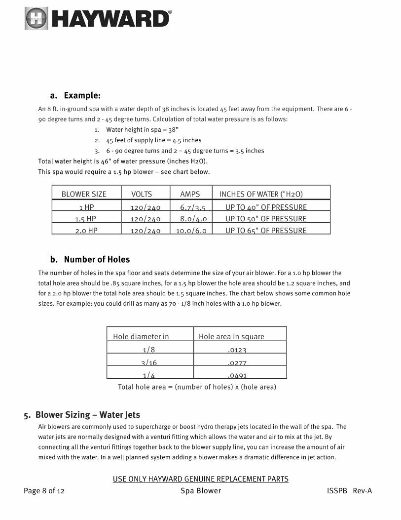
a. Example: An 8 ft. in-ground spa with a water depth of 38 inches is located 45 feet away from the equipment. There are 6 -
90 degree turns and 2 - 45 degree turns. Calculation of total water pressure is as follows:
1. Water height in spa = 38”
2. 45 feet of supply line = 4.5 inches
3. 6 - 90 degree turns and 2 – 45 degree turns = 3.5 inches
Total water height is 46" of water pressure (inches H2O).
This spa would require a 1.5 hp blower – see chart below.
BLOWER SIZE VOLTS AMPS INCHES OF WATER ("H2O)
1 HP 120/240 6.7/3.5 UP TO 40" OF PRESSURE 1.5 HP 120/240 8.0/4.0 UP TO 50" OF PRESSURE 2.0 HP 120/240 10.0/6.0 UP TO 65" OF PRESSURE
b. Number of Holes The number of holes in the spa floor and seats determine the size of your air blower. For a 1.0 hp blower the
total hole area should be .85 square inches, for a 1.5 hp blower the hole area should be 1.2 square inches, and
for a 2.0 hp blower the total hole area should be 1.5 square inches. The chart below shows some common hole
sizes. For example: you could drill as many as 70 - 1/8 inch holes with a 1.0 hp blower.
Hole diameter in Hole area in square
1/8 .0123
3/16 .0277
1/4 .0491Total hole area = (number of holes) x (hole area)
5. Blower Sizing – Water Jets Air blowers are commonly used to supercharge or boost hydro therapy jets located in the wall of the spa. The
water jets are normally designed with a venturi fitting which allows the water and air to mix at the jet. By
connecting all the venturi fittings together back to the blower supply line, you can increase the amount of air
mixed with the water. In a well planned system adding a blower makes a dramatic difference in jet action.
SA
VE
TH
ES
EIN
ST
RU

USE ONLY HAYWARD GENUINE REPLACEMENT PARTS Page 9 of 12 Spa Blower ISSPB Rev-A
6. New Spa Applications
a. Determine the number of water jets required in your spa. Next choose the correct size water
pump - the water jet manufacturer will supply horsepower per-jet guidelines to help you
choose. Loop air line above water level as per Diagram #2. It is important to size the water
pump correctly for the number and size of water jets in your spa. Improper sizing can
cause both blower and water pump to overheat and or water to back up into the
blower.
b. Choose the correct size blower based on the number of water jets in your spa. See
the chart below. Note that you may require a larger blower if your installation
differs significantly from the standard installation. Please refer to the installation
guidelines for more details.
BLOWER SIZE VOLTS AMPS NUMBER OF WATER JETS
1 HP 120/240 6.7/3.5 4 TO 8 1.5 HP 120/240 8.0/4.0 8 TO 12 2.0 HP 120/240 10.0/6.0 14 OR MORE
7. Blower Replacement – Existing Spa Determining the size of blower for an existing spa is more difficult since many factors including length of
supply line and number of 90 degree turns are unknown under concrete and decking.
a. Use the sizing chart above as a good starting point based on standard installation. b. Check the size of the water pump and see if it is sized correctly based on the number of water jets.
A good rule of thumb is 1/4 hp for every water jet. Run the water pump without the blower and check the air line for signs of water backing up.
c. Allow the blower to run for 30 minutes and check that air is exiting all water jets.
d. Use a Magnehelic pressure gauge (0-100 inches) to measure back pressure while blower is
operating. See trouble shooting guidelines for complete details.

USE ONLY HAYWARD GENUINE REPLACEMENT PARTS Page 10 of 12 Spa Blower ISSPB Rev-A

USE ONLY HAYWARD GENUINE REPLACEMENT PARTS Page 11 of 12 Spa Blower ISSPB Rev-A
8. Warranty *Retain this Warranty Certificate in a safe and convenient location for your records
9. Product Registration
HAYWARD LIMITED WARRANTY To buyer, as original purchaser of this equipment, Hayward Pool Products, 620 Division Street, Elizabeth, New Jersey, warrants its products to be free from defects in materials and workmanship for a period of (see below) from the date of purchase. Parts which fail or become defective during the warranty period, except as a result of freezing, negligence, improper installation, use, or care, shall be repaired or replaced, at our option, without charge, within 90 days of the receipt of defective product, barring unforeseen delays. To obtain warranty replacements or repair, defective components or parts should be returned, transportation paid, to the place of purchase, or to the nearest authorized Hayward service center. For further Hayward dealer or service center information, contact Hayward customer service department. No returns may be made directly to the factory without the express written authorization of Hayward pool Products. To original purchasers of this equipment, Hayward Pool Products warrants its products to be free from defects in materials and workmanship for a period of (see below) from the date of purchase. Filters which become defective during the warranty period, except as a result of freezing, negligence, improper installation, use or care, shall be repaired or replaced, at our option, without charge, All other conditions and terms of the standard warranty apply. Hayward shall not be responsible for cartage, removal and/or reinstallation labor or any other such costs incurred in obtaining warranty replacements. The Hayward Pool Products warranty does not apply to components manufactured by others. For such products, the warranty established by the respective manufacturer will apply. Some states do not allow a limitation on how long an implied warranty lasts, or the exclusion or limitation of incidental or consequential damages, so the above limitation or exclusion may not apply to you.
DATE OF INSTALLATION ____________________
INITIAL PRESSURE GAUGE READING (CLEAN FILTER) _______________________
PUMP MODEL __________________

USE ONLY HAYWARD GENUINE REPLACEMENT PARTS Page 12 of 12 Spa Blower ISSPB Rev-A
DETACH HERE: Fill out bottom portion completely and mail within 10 days of purchase/installation or register online.
-----------------------------------------------------------------------------------------------------------------------------------------
Spa Blower Warranty Card Registration
Years Pool has been in service
< 1 year 1-3 4-5 6-10 11-15 >15
Purchased from_____________________________
Builder Retailer Pool Service Internet/Catalog
Company Name_________________________________
Address_______________________________________
City____________________ State_____ Zip__________
Phone_________________________________________
Type of Pool: Concrete/Gunite Vinyl Fiberglass Other_____________________________
New Installation Replacement
Installation for:
In Ground Spa
-