ISSN : 2454-9150 Vol-06, Issue-08, NOV 2020 Cross-Cultural ...

International Journal for Research in Engineering Application & Management (IJREAM)
ISSN : 2454-9150 Vol-05, Issue-01, April 2019
192 | IJREAMV05I0149032 DOI : 10.18231/2454-9150.2019.0296 © 2019, IJREAM All Rights Reserved.
Embedded Dry Block Calibrator for Intermediate
Temperature 1K. Mohan Raj,
2R. Anirudh Viswanath,
3A.M. Azar Farooq,
4J. Deepak Raj,
5M. Siva Bharathi
1Assistant Professor,
2,3,4,5UG Students, Department of Instrumentation and Control Engineering,
Sri Sairam engineering college, Chennai, India, [email protected]
Abstract Calibration is an important procedure that must always be considered to assure measurement system’s
accuracy measurement errors namely offset and linearization errors can be compensated as long as timely calibration
routines are performed in the measurement system. The intent of this project is to test and calibrate temperature gauge
and temperature transmitters. The calibrator is designed with a microcontroller (89C51ED2) provided with flash
memory of 64KB. The microcontroller applies a correction factor to the converted data, thus increasing the overall
accuracy. The controller is also interfaced with a keypad and a display. The converted digital data can be displayed in
15 different units of temperature. The switching the three physical quantities is done using MUX (DG408). Since the
controller has a flash memory coding can be downloaded and future advancements can be made. The developed
calibrator can calibrate temperature sensors in the intermediate temperature range of 50 to 800 degree centigrade at
high accuracy of (±) 1°C of full-scale reading. Thus, an embedded based portable calibrator system is developed in our
project.
Keywords —Calibrator, Intermediate temperature range, embedded calibrator system.
I. INTRODUCTION
In industrial power plants, a number of temperature sensors
and transmitters are fitted in the pipelines at various points
in order to measure the temperature at those points. These
transmitters and sensors have to be calibrated every 3
months, 6 months a year according to the need in order to
maintain the measurement‟s accuracy and produce correct
output. This is done with the help of temperature calibrator
which is master, having it accuracy higher than that of the
instrument to be calibrated.
II. CALIBRATION
The formal definition of calibration by the International
Bureau of Weights and Measures (BIPM) is the following:
"Operation that, under specified conditions, in a first step,
establishes a relation between the quantity values with
measurement uncertainties provided by measurement
standards and corresponding indications with associated
measurement uncertainties (of the calibrated instrument or
secondary standard) and, in a second step, uses this
information to establish a relation for obtaining a
measurement result from an indication. Calibration is the
comparison between measurements – one of known quantity
or correctness made with one device and another
measurement made in a similar way as possible with a
second device. The first device is known as the standard
with high precision and the second device is known as the
test instrument or unit under test.
The increasing need for known accuracy and uncertainty
and the need to have consistent and comparable standards
internationally has led to the establishment of national
laboratories. In many countries a National Metrology
Institute (NMI) will exist which will maintain primary
standards of measurement (the main SI units plus a number
of derived units) which will be used to
provide traceability to customer's instruments by
calibration.
The NMI supports the metrological infrastructure in that
country (and often others) by establishing an unbroken
chain, from the top level of standards to an instrument used
for measurement. Examples of National Metrology
Institutes are NPL in the UK, NIST in the United
States, PTB in Germany and many others. Since the Mutual
Recognition Agreement was signed it is now
straightforward to take traceability from any participating
NMI and it is no longer necessary for a company to obtain
traceability for measurements from the NMI of the country
in which it is situated, such as the National Physical
Laboratory in the UK.
A. NEED FOR CALIBRATION
Calibration may be required for the following reasons, a
new instrument After an instrument has been repaired or
modified When a specified time period has elapsed When a
specified usage (operating hours) has elapsed Before and/or
after a critical measurement After an event, for example

International Journal for Research in Engineering Application & Management (IJREAM)
ISSN : 2454-9150 Vol-05, Issue-01, April 2019
193 | IJREAMV05I0149032 DOI : 10.18231/2454-9150.2019.0296 © 2019, IJREAM All Rights Reserved.
After an instrument has been exposed to a shock, vibration,
or physical damage, which might potentially have
compromised the integrity of its calibration Sudden changes
in weather Whenever observations appear questionable or
instrument indications do not match the output of surrogate
instruments As specified by a requirement, e.g. customer
specification, instrument manufacturer recommendation.
Calibration is necessary for measuring devices as it enables
precise measurement of values and allows greater accuracy.
It removes and rectifies errors and corrects the problem of
sloppy performance. Calibration defines the accuracy and
quality of measurements recorded using a piece of
equipment. Over time there is a tendency for results and
accuracy to ‘drift’ particularly when using particular
technologies or measuring particular parameters such as
temperature and humidity. To be confident in the results
being measured there is an ongoing need to maintain the
calibration of equipment throughout its lifetime for reliable,
accurate and repeatable measurements. The goal of
calibration is to minimize any measurement uncertainty by
ensuring the accuracy of test equipment. Calibration
quantifies and controls errors or uncertainties within
measurement processes to an acceptable level.
B. TEMPERATURE CALIBRATION
Temperature calibration can be accomplished in a variety of
ways and with various degrees of accuracy. As with any
calibration, a standard must be used. The standards used
in temperature calibration can come in different forms but
must be certified with an accuracy that is traceable to a
national standard. In industrial applications temperature
calibration usually involves thermistors, thermocouples or
Platinum resistance thermometers (PRTs), also called
resistance temperature devices (RTDs). These are devices
used to accurately measure temperature. Readings from
these devices can be compared with less accurate field
temperature sensors and used to evaluate the viability of
those devices or to perform a temperature calibration. For a
manufacturing facility, it is important to maintain quality
assurance and cGMP. One of the main areas to be
considered is calibration of temperature equipment.
Temperature instrument calibration, which is a process of
comparing measurements from a test temperature device
against a standard must be carried out regularly. The
standard is a device that has a known frequency, which is
traceable to national or international standards. If there is
any deviation from the standard, it is recorded. And, that
drift must be corrected. Temperature instrument calibration,
which is a process of comparing measurements from a test
temperature device against a standard must be carried out
regularly. The standard is a device that has a known
frequency, which is traceable to national or international
standards. If there is any deviation from the standard, it is
recorded. And, that drift must be corrected.
Temperature calibration can be done using the following
ways:
Intrinsic Standards: This process will be heavy on your
pockets and is generally limited to calibration labs. It is also
adapted in plants which house a department specializing in
high-end metrology. However, these intrinsic standards are
the most accurate forms of temperature calibrators. They
include triple point of water or melting point of metals such
as zinc, indium, and aluminum. All these methods occur
naturally. You will require multiple standards to cover the
entire range of the typical temperature calibrations.
Liquid Bath Calibrators: These calibrators comprise of a
liquid (generally oil), a stirring mechanism and a
heating/cooling element. You can expect uniform
specifications throughout, as the liquid is constantly stirred
and circulated through the bath. Liquid bath calibrators are
the best to calibrate odd-shaped or extremely small sensors
due to the uniform circulation of the liquid.
Dry block calibrators: As the name suggests, dry block
calibrators consist of a heating block, an internal sensor and
control mechanism to reach and maintain the desired
temperature range. They have a heating and cooling element
as well, but no liquid is used in this process. This makes
them portable and easy to maintain. One of the major
advantages of these calibrators is that they can reach the
desired temperature much faster as compared to traditional
baths; however, they are less accurate and stable than them.
Thanks to technological developments, the performance of
dry block calibrators is improving in terms of accuracy and
stability.
Electronic calibrators: These calibrators can simulate the
Sensors under Test (SUT) and provide the readout results
on the sensor’s performance. Their main drawback is that
the integrity of the sensor cannot be tested as there is no
temperature source to which the sensor can be subjected.
However, they are more affordable as compared to
traditional liquid baths or dry-block calibrators, and are also
quite portable.
Thus, calibrating temperature sensors is of great
importance. And in industries such as pharmaceutical, food
and beverage, it holds much more significance. So, you
must understand how to calibrate an instrument and which
calibration methods suit your instruments and processes the
best.

International Journal for Research in Engineering Application & Management (IJREAM)
ISSN : 2454-9150 Vol-05, Issue-01, April 2019
194 | IJREAMV05I0149032 DOI : 10.18231/2454-9150.2019.0296 © 2019, IJREAM All Rights Reserved.
III. WORKINGTHEORY
FIG 1: BLOCK DIAGRAM
Thermowell is used to produce the reference heat supplied.
The RTD is used as a sensor to convert temperature to
resistance. The constant current generator is used to
produce an output in terms of mA. The signal conditioning
circuit converts the analog to digital signal and then
amplifies it to the micro controller. A 230v supply is given
to the whole circuit. Each module in the calibrator requires
appropriate power supply in order to achieve optimum
results. The power supply circuit is divided into four
segments. The first segment generates +15v. The second
generates -5v. The third generates +12v for the micro
controller. The POR/PFD function monitors the internal
power-supply of the CPU core memories and the
peripherals, and if needed, suspends their activity when the
internal power supply falls below a safety threshold. This is
achieved by applying an internal reset to them. By
generating the Reset the Power Monitor insures a correct
start up when AT89C51ED2is powered up. In order to
startup and maintain the microcontroller in correct operating
mode, VCC has to be stabilized in the VCC operating range
and the oscillator has to be stabilized with a nominal
amplitude compatible with logic level VIH/VIL. Idle mode
is a power reduction mode that reduces the power
consumption. In this mode, program execution halts. Idle
mode freezes the clock to the CPU at known states while the
peripherals continue to be clocked. The CPU status before
entering idle mode is preserved, i.e. the program counter
and program status word register retain their data for the
duration of idle mode. The contents of the SFRs and RAM
are also retained. Generation of reference voltage The
reference voltage is created using the IC LT1014. This
circuit is known as the Amplification circuit. The AD581 is
used as the trim part of the circuit.
Fig 2: Amplifier Circuit
The LT1014, LT1014A, and LT1014D are quad precision
operational amplifiers with 14-pinindustry-standard
configuration. They feature low offset-voltage temperature
coefficient, high gain, low supply current, and low noise.
The LT1014, LT1014A, and LT1014D can be operated
with both dual ±15V AND -5V. The common-mode input
voltage range includes ground, and the output voltage can
also swing to within a few millivolts of ground. The
AD5811 is a 3-pin, temperature compensated, monolithic,
band gap voltage reference that provides a precise 10.00 V
output from an unregulated input level ranging from 12 V to
30 V. Laser wafer trimming (LWT) is used to trim both the
initial error at +25°C as well as the temperature coefficient,
resulting in high precision performance previously available
only in expensive hybrids or oven regulated modules. The
5mV initial error tolerance and 5 ppm/°C guaranteed
temperature coefficient of the AD581L is available in a
monolithic voltage reference. The band gap circuit design
used in the AD581 offers several advantages over classical
Zener breakdown diode techniques. Most important, no
external components are required to achieve full accuracy
and significant stability to low power systems. In addition,
total supply current to the device, including the output
buffer amplifier (which can supply up to 10 mA) is typically
750 μA. The long-term stability of the band gap design is
equivalent to selected Zener reference diodes. The AD581
is recommended for use as a reference for 8-, 10- or 12-bit
digital-to-analog converters (DACs) that require an external
precision reference. The device is also ideal for all types of
analog-to-digital converters (ADCs) up to 14-bit accuracy,
either successive approximation or integrating designs, and
can generally offer better performance than that provided by
standard self-contained references. The AD7703 is a 20-bit
ADC which uses a sigma delta conversion technique. The
analog input is continuously sampled by an analog
modulator whose mean output duty cycle is proportional to
the input signal.
Fig 3: ADC Circuit
The inherent linearity of the ADC is excellent, and end
point accuracy is ensured by self-calibration of zero and full
scale which may be initiated at any time. The output data is
accessed through a serial port, which has two synchronous
modes suitable for interfacing to shift registers or the serial
International Journal for Research in Engineering Application & Management (IJREAM)
ISSN : 2454-9150 Vol-05, Issue-01, April 2019
195 | IJREAMV05I0149032 DOI : 10.18231/2454-9150.2019.0296 © 2019, IJREAM All Rights Reserved.
ports of industry standard microcontrollers. CMOS
construction ensures low power dissipation, and a power
down mode reduces the idle power consumption to only 10
MW. In operation, the sampled analog signal is fed to the
Subtract, along with the output of the 1-bit DAC. The
filtered difference signal is fed to the comparator, whose
output samples the difference signal at a frequency many
times that of the analog signal frequency. Oversampling is
fundamental to the operation of sigma-delta.
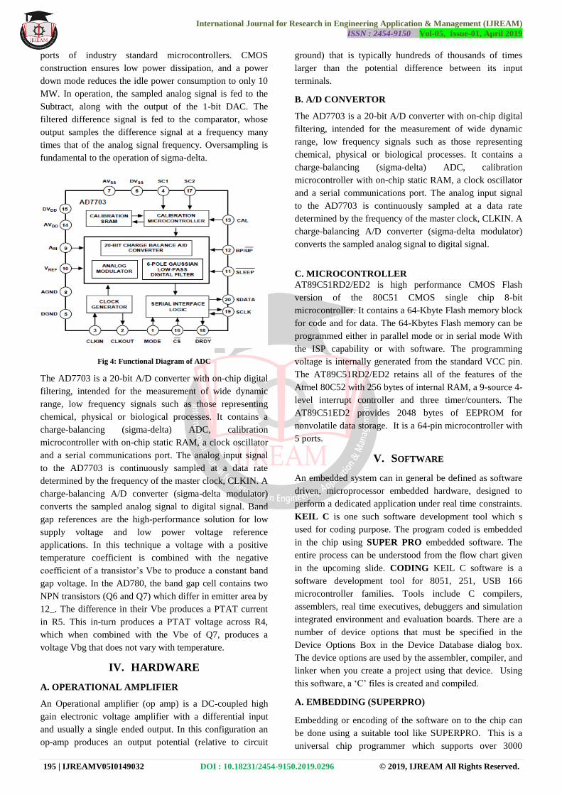
Fig 4: Functional Diagram of ADC
The AD7703 is a 20-bit A/D converter with on-chip digital
filtering, intended for the measurement of wide dynamic
range, low frequency signals such as those representing
chemical, physical or biological processes. It contains a
charge-balancing (sigma-delta) ADC, calibration
microcontroller with on-chip static RAM, a clock oscillator
and a serial communications port. The analog input signal
to the AD7703 is continuously sampled at a data rate
determined by the frequency of the master clock, CLKIN. A
charge-balancing A/D converter (sigma-delta modulator)
converts the sampled analog signal to digital signal. Band
gap references are the high-performance solution for low
supply voltage and low power voltage reference
applications. In this technique a voltage with a positive
temperature coefficient is combined with the negative
coefficient of a transistor‟s Vbe to produce a constant band
gap voltage. In the AD780, the band gap cell contains two
NPN transistors (Q6 and Q7) which differ in emitter area by
12_. The difference in their Vbe produces a PTAT current
in R5. This in-turn produces a PTAT voltage across R4,
which when combined with the Vbe of Q7, produces a
voltage Vbg that does not vary with temperature.
IV. HARDWARE
A. OPERATIONAL AMPLIFIER
An Operational amplifier (op amp) is a DC-coupled high
gain electronic voltage amplifier with a differential input
and usually a single ended output. In this configuration an
op-amp produces an output potential (relative to circuit
ground) that is typically hundreds of thousands of times
larger than the potential difference between its input
terminals.
B. A/D CONVERTOR
The AD7703 is a 20-bit A/D converter with on-chip digital
filtering, intended for the measurement of wide dynamic
range, low frequency signals such as those representing
chemical, physical or biological processes. It contains a
charge-balancing (sigma-delta) ADC, calibration
microcontroller with on-chip static RAM, a clock oscillator
and a serial communications port. The analog input signal
to the AD7703 is continuously sampled at a data rate
determined by the frequency of the master clock, CLKIN. A
charge-balancing A/D converter (sigma-delta modulator)
converts the sampled analog signal to digital signal.
C. MICROCONTROLLER
AT89C51RD2/ED2 is high performance CMOS Flash
version of the 80C51 CMOS single chip 8-bit
microcontroller. It contains a 64-Kbyte Flash memory block
for code and for data. The 64-Kbytes Flash memory can be
programmed either in parallel mode or in serial mode With
the ISP capability or with software. The programming
voltage is internally generated from the standard VCC pin.
The AT89C51RD2/ED2 retains all of the features of the
Atmel 80C52 with 256 bytes of internal RAM, a 9-source 4-
level interrupt controller and three timer/counters. The
AT89C51ED2 provides 2048 bytes of EEPROM for
nonvolatile data storage. It is a 64-pin microcontroller with
5 ports.
V. SOFTWARE
An embedded system can in general be defined as software
driven, microprocessor embedded hardware, designed to
perform a dedicated application under real time constraints.
KEIL C is one such software development tool which s
used for coding purpose. The program coded is embedded
in the chip using SUPER PRO embedded software. The
entire process can be understood from the flow chart given
in the upcoming slide. CODING KEIL C software is a
software development tool for 8051, 251, USB 166
microcontroller families. Tools include C compilers,
assemblers, real time executives, debuggers and simulation
integrated environment and evaluation boards. There are a
number of device options that must be specified in the
Device Options Box in the Device Database dialog box.
The device options are used by the assembler, compiler, and
linker when you create a project using that device. Using
this software, a „C‟ files is created and compiled.
A. EMBEDDING (SUPERPRO)
Embedding or encoding of the software on to the chip can
be done using a suitable tool like SUPERPRO. This is a
universal chip programmer which supports over 3000
International Journal for Research in Engineering Application & Management (IJREAM)
ISSN : 2454-9150 Vol-05, Issue-01, April 2019
196 | IJREAMV05I0149032 DOI : 10.18231/2454-9150.2019.0296 © 2019, IJREAM All Rights Reserved.
devices, including EPROM, EEPROM, and FLASH
memories, Programmable logic and Microcontrollers The
SUPERPRO is a family of affordable, reliable, and fast
universal device programmers. They are designed to
communicate with the parallel port or USB and to operate
with the Intel 80386-, 80486-, and Pentium based IBM
compatible desktop computers and notebook computers.
The menu-driven software interface makes them easy to
operate. Any kind of modifications to the coding can be
done by any number of embedding and de-embedding. The
„C‟ file that was created by KEIL C is converted to a „HEX‟
file by this software.
B. ALGORITHM
Step 1: Assign appropriate ports of micro-controller to
CSO, CSI, CS2, CAL, LBAT, and switch and also the
pressure scan time and ma, voltage scan time and their
respective over range values are defined.
Step 2: In the next step the function blocks to, initialize
ports to check over pressure, to check milliamp range,
voltage range and the battery are declared and defined. And
also, the test switch and its menu are declared and defined.
Step3: When the device is switched on, the function block
for initializing ports is called. Then the micro-controller
reads the unit and pressure from their respective addresses.
After execution of each function block, the status of the
battery is checked by calling its function block.
Step 4: Then either pressure or current or voltage can be
measured by calling their function blocks within their
respective scan time. The mean pack can also be measured.
Step 5: After the measurement of pressure, the analog result
is then sent to ADC for conversion. “ADC_INTO” is used
to call ADC module and its initialization.
Step 6: The graphic display is also initialized and kept
ready by calling “INITGLEDO” function.
Step 7: In ADC, the ready pin is active low. Hence, when
data is ready to be received for conversion, “READY” is
made low.
Step 8: CS of ADC is made low since micro controller
should not access ADC during conversion process.
Step 9: The input of the ADC is got as serial bits and these
bits entre a loop of 20 iteration which does the conversion.
Step 10: CS of ADC is made high after the digital output is
achieved after conversion so that the micro controller can
access it.
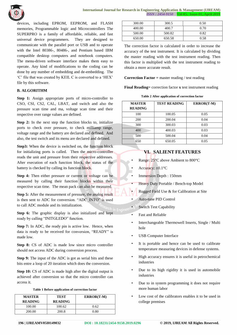
Table 1 Before application of correction factor
MASTER
READING
TEST
READING
ERROR(T-M)
100.00 100.62 0.62
200.00 200.8 0.80
300.00 300.5 0.50
400.00 400.7 0.70
500.00 500.82 0.82
650.00 650.58 0.58
The correction factor is calculated in order to increase the
accuracy of the test instrument. It is calculated by dividing
the master reading with the test instrument reading. Then
this factor is multiplied with the test instrument reading to
obtain a more accurate result.
Correction Factor = master reading / test reading
Final Reading= correction factor x test instrument reading
Table 2 After application of correction factor
MASTER
READING
TEST READING ERROR(T-M)
100 100.05 0.05
200 200.04 0.04
300 300.03 0.03
400 400.03 0.03
500 500.04 0.04
650 650.05 0.05
VI. SALIENT FEATURES
• Range: 25°C above Ambient to 800°C
• Accuracy: ±0.1°C
• Immersion Depth : 150mm
• Heavy Duty Portable / Bench-top Model
• Rugged Field Use & for Calibration at Site
• Auto-tune PID Control
• Switch Test Capability
• Fast and Reliable
• Interchangeable Thermowell Inserts, Single / Multi
hole
• USB Computer Interface
• It is portable and hence can be used to calibrate
temperature measuring devices in defense systems.
• High accuracy ensures it is useful in petrochemical
industries
• Due to its high rigidity it is used in automobile
industries
• Due to in system programming it does not require
more human labor
• Low cost of the calibrators enables it to be used in
college premises

International Journal for Research in Engineering Application & Management (IJREAM)
ISSN : 2454-9150 Vol-05, Issue-01, April 2019
197 | IJREAMV05I0149032 DOI : 10.18231/2454-9150.2019.0296 © 2019, IJREAM All Rights Reserved.
VII. RESULTS AND CONCLUSION
The temperature calibrator designed is used as a high
accuracy master standard to calibrate resistance
thermometer and transmitter. This calibrator has an
accuracy of 0.02% and therefore can be used to calibrate
wide range of temperatures. The calibration process is
carried out for the resistance thermometer and
thermocouple. The error is calculated comparing with the
master and the reading are noted down. The readings are
shown in the next slide Measurement errors namely offset
and linearization errors were compensated as long as timely
calibration routines are performed in the measurement
system. This project tests and calibrates temperature gauge
and temperature transmitters. It is easily portable and
provided with an internal thermowell for temperature
generation. This device can calibrate temperature sensor
from 60 to 350 degree centigrade at high accuracy of
+0.025% of full-scale reading. A pt100 sensor converts the
physical quantity into an electrical signal. The analog data
is converted to digital form using a 20-bit Analog to Digital
Converter. This calibrator is designed with a
Microcontroller (89C61RD2) provided with flash memory
of 64KB so that the coding can be downloaded and any
future advancements be made for this calibrator. The micro
controller applies a correction factor to the converted data,
thus increasing the overall accuracy. This controller is also
interfaced with a keypad and a display. The converted
digital data can be displayed in 15 different units of
temperature. The switching between the three physical
quantities is done using MUX (DG408).
TABLE 2 RESULT ANALYSIS
S No Read
Value
(Degree
Celcius)
Actual
Value
(Degree
Celcius)
Deviation
Remarks
1 100 100.02 0.02 PASS
2 200 200.03 0.03 ACCEPTED
3 300 300.01 0.01 ACCEPTED
4 400 400.12 0.12 REJECTED
5 500 500.02 0.02 ACCEPTED
6 650 650.01 0.01 ACCEPTED
7 670 670.03 0.03 ACCEPTED
8 700 700.07 0.07 ACCEPTED
9 730 730.03 0.03 ACCEPTED
10 750 750.05 0.05 ACCEPTED
From the above table, it can be inferred that the unit under
test passed the calibration test 9 out of 10 times. Hence it is
concluded that it has an accuracy of 90%. The accuracy of
the unit can be improved by taking a more number of
calibrating measurements. The future scope for temperature
calibrator is based on the micro controller used and the
analog to digital converter used. The heating rods used
could be of higher resistance to corrosion. Higher range of
temperature calibration could be made possible by using
different components. Safety measures for the apparatus
could be developed by placing sticker near bath and power
supply area. Development in the software side can be done
by using other software tool to program the micro controller
to reduce to random access memory
REFERENCES
[1] Orzylowski M., Sankowski D, “Automated
Calibration of Temperature Sensors” The 16th IEEE
Instrumentation and Measurement Technology
Conference, IMTC‟99, pp. 16-21, 24-26 May, 1999,
Venice, Italy.
[2] NajidahHambali ShahrizalSaat, MohdAshraf Ahmad,
MohdSyakirin Ramli, “Computer-based System for
Calibration of Temperature Transmitter using RTD”,
2010 3rd International Conference on Information
Management, Innovation Management and Industrial
Engineering
[3] NajidahHambali, ShahrizalSaat, MohdSyakirinRamli,
MustaqimHazmi, “Automatic Detection Computer-
based (ADCob)System for Temperature Measurement
Calibrationof RTD”, International Conference on
Electrical, Control and Computer Engineering, Pahang,
Malaysia, June 21-22, 2011
[4] Yi Xianjun, Liu Cuimei, “Development of High-
precision Temperature Measurement System Based on
ARM”, The Ninth International Conference on
Electronic Measurement & Instruments.
[5] Michiel A. P. Pertijs, André L. Aita, Kofi A. A.
Makinwa, and Johan H. Huijsing, “Low-Cost
Calibration Techniques forSmart Temperature
Sensors”, IEEE SENSORS JOURNAL, VOL. 10, NO.
6, JUNE 2010.
[6] R. A. Koestoera)
, Y. A. Saleh, I. Roihan,
and Harinaldi “A simple method for calibration of
temperature sensor DS18B20 waterproof in oil bath
based on Arduino data acquisition system” , AIP
Conference Proceedings 2062, 020006 (2019).
[7] Chua-Chin Wang, Zong-You Hou, and Jhih-Cheng
You, “A High-Precision CMOS Temperature Sensor
with Thermistor Linear Calibration in the (−5 °C, 120
°C) Temperature Range” Sensors 2018, 18(7), 2165.
[8] http://www.alldatasheet.com
[9] http://www.fluke.com