ISSN 2277 7164 Original Article Polydimethylsiloxane ...urpjournals.com/tocjnls/1_14v4i3_2.pdf ·...
9
43 Advances in Polymer Science and Technology: An International Journal 2014; 4(3): 43-51 ISSN 2277 – 7164 Original Article Modeling of Young’s Modulus of Thermoplastic Polyurethane and Polydimethylsiloxane Rubber Blends Based on Phase Morphology Jineesh Ayippadath Gopi · Golok Bihari Nando* Rubber Technology Centre, Indian Institute of Technology Kharagpur, West Bengal, India, 721302 *Corresponding author email: [email protected] Author email: [email protected] Received 17 August 2014; accepted 09 September 2014 Abstract Young’s modulus of blends of Thermoplastic polyurethane (TPU) and Polydimethylsiloxane rubber (PDMS) are measured throughout the composition range. Comparison and evaluation between the experimental results and the theoretical predictions based on different developed models for the Young’s modulus have been presented based on both droplet/matrix and co-continuous morphology. Both two dimensional (parallel, series, Takayanagi, Davies and Coran-Patel models) and three dimensional (Barentsen and Nijhof) models were selected for predicting Young’s modulus of the blends. Emphasis was given to the tensile strain behavior of weak PDMS phase and the stiff TPU phase in each blend and the dependence of their behavior in the Young’s modulus values predicted by the models. The blends with finely dispersed PDMS phase in TPU matrix show relatively comparable Young’s moduli as predicted by Takayanagi parallel model, and Barentsen series model of parallel parts due to equal elongation for both the phases and the very small strain gradient between the parallel parts in the model. Young’s moduli of the blends with dispersed TPU in PDMS major matrix show comparable results as predicted by Takayanagi series model and Barentsen parallel model of serial parts because of the weak PDMS matrix and the limited influence of the strain on the stiff dispersed TPU domains. Experimental Young’s modulus of the blends with co-continuity in its morphology is similar to the predicted values as per Nijof and Coran-Patel model which are based on co-continuous morphology. © 2014 Universal Research Publications. All rights reserved Key Words: phase morphology, thermoplastic polyurethane, polydimethylsiloxane rubber, polymer blends, scanning electron microscopy Introduction Synthesis of new polymers with specific end use properties is an expensive and time consuming process as it involves several tedious and hazardous manufacturing steps. The process of blending of polymers to develop new materials commenced in late part of the 20 th century has become very popular in the area of polymer science and engineering. Blending of two or more different polymers with wider range of properties became an effective and inexpensive route to produce new materials with specific end use properties. The properties of a multiphase polymer system cannot be deduced from the properties of the individual phases. Instead, the properties depend on many factors, such as the spatial organization of each phase and the nature of the interface. Most of the polymer blends are often produced by melt-mixing technique, which generates different types of morphology. Factors governing the morphology of the blends are composition, interfacial tension, processing conditions and rheological characteristics of the components [1-3]. In general, polymer blend morphology can be divided into different classes, i.e. dispersed, stratified and co-continuous morphology. Dispersions of droplets of the minor phase in a matrix of the major phase are most common and are characterized under dispersed morphology. When the content of the minor phase increases, it is possible that both the components may present in a continuous network, which is known as the co- continuous morphology. Stratified morphology is made up of alternate layers of the two phases. The types and scales of the morphologies determine the blend characteristics [4- 5]. Among various parameters, mechanical properties are useful for deducing the morphology or phase continuity in multiphase polymer blend systems. One of the key factors for achieving the desired properties is the control of the type and dimensions of the morphology. Droplet – matrix morphology can improve the impact properties, fibrillar morphology may result in better tensile properties, blends with lamellar structures enhance barrier properties and co-continuous morphology show a combination of the characteristics of both the polymer components [6-10]. The blend component with the lowest viscosity and highest Available online at http://www.urpjournals.com Advances in Polymer Science and Technology: An International Journal Universal Research Publications. All rights reserved
Transcript of ISSN 2277 7164 Original Article Polydimethylsiloxane ...urpjournals.com/tocjnls/1_14v4i3_2.pdf ·...

43 Advances in Polymer Science and Technology: An International Journal 2014; 4(3): 43-51
ISSN 2277 – 7164
Original Article
Modeling of Young’s Modulus of Thermoplastic Polyurethane and
Polydimethylsiloxane Rubber Blends Based on Phase Morphology
Jineesh Ayippadath Gopi · Golok Bihari Nando*
Rubber Technology Centre, Indian Institute of Technology Kharagpur, West Bengal, India, 721302
*Corresponding author email: [email protected]
Author email: [email protected]
Received 17 August 2014; accepted 09 September 2014 Abstract
Young’s modulus of blends of Thermoplastic polyurethane (TPU) and Polydimethylsiloxane rubber (PDMS) are measured
throughout the composition range. Comparison and evaluation between the experimental results and the theoretical
predictions based on different developed models for the Young’s modulus have been presented based on both
droplet/matrix and co-continuous morphology. Both two dimensional (parallel, series, Takayanagi, Davies and Coran-Patel
models) and three dimensional (Barentsen and Nijhof) models were selected for predicting Young’s modulus of the blends.
Emphasis was given to the tensile strain behavior of weak PDMS phase and the stiff TPU phase in each blend and the
dependence of their behavior in the Young’s modulus values predicted by the models. The blends with finely dispersed
PDMS phase in TPU matrix show relatively comparable Young’s moduli as predicted by Takayanagi parallel model, and
Barentsen series model of parallel parts due to equal elongation for both the phases and the very small strain gradient
between the parallel parts in the model. Young’s moduli of the blends with dispersed TPU in PDMS major matrix show
comparable results as predicted by Takayanagi series model and Barentsen parallel model of serial parts because of the
weak PDMS matrix and the limited influence of the strain on the stiff dispersed TPU domains. Experimental Young’s
modulus of the blends with co-continuity in its morphology is similar to the predicted values as per Nijof and Coran-Patel
model which are based on co-continuous morphology.
© 2014 Universal Research Publications. All rights reserved
Key Words: phase morphology, thermoplastic polyurethane, polydimethylsiloxane rubber, polymer blends, scanning
electron microscopy
Introduction
Synthesis of new polymers with specific end use properties is an
expensive and time consuming process as it involves several tedious
and hazardous manufacturing steps. The process of blending of
polymers to develop new materials commenced in late part of the
20th century has become very popular in the area of polymer science
and engineering. Blending of two or more different polymers with
wider range of properties became an effective and inexpensive route
to produce new materials with specific end use properties. The
properties of a multiphase polymer system cannot be deduced from
the properties of the individual phases. Instead, the properties
depend on many factors, such as the spatial organization of each
phase and the nature of the interface. Most of the polymer blends
are often produced by melt-mixing technique, which generates
different types of morphology. Factors governing the morphology
of the blends are composition, interfacial tension, processing
conditions and rheological characteristics of the components [1-3].
In general, polymer blend morphology can be
divided into different classes, i.e. dispersed, stratified and
co-continuous morphology. Dispersions of droplets of the
minor phase in a matrix of the major phase are most
common and are characterized under dispersed
morphology. When the content of the minor phase
increases, it is possible that both the components may
present in a continuous network, which is known as the co-
continuous morphology. Stratified morphology is made up
of alternate layers of the two phases. The types and scales
of the morphologies determine the blend characteristics [4-
5].
Among various parameters, mechanical properties
are useful for deducing the morphology or phase continuity
in multiphase polymer blend systems. One of the key
factors for achieving the desired properties is the control of
the type and dimensions of the morphology. Droplet–
matrix morphology can improve the impact properties,
fibrillar morphology may result in better tensile properties,
blends with lamellar structures enhance barrier properties
and co-continuous morphology show a combination of the
characteristics of both the polymer components [6-10]. The
blend component with the lowest viscosity and highest
Available online at http://www.urpjournals.com
Advances in Polymer Science and Technology: An International Journal
Universal Research Publications. All rights reserved
44 Advances in Polymer Science and Technology: An International Journal 2014; 4(3): 43-51
volume fraction forms the continuous phase, whereas the
blend component with the highest viscosity and lowest
volume fraction forms the dispersed phase. The continuity
of phases has a great impact on the resultant macroscopic
properties of the blends.
Percolation theory deals with the development of
continuity in the polymer blends. According to this theory,
at lower concentrations of the phase, dispersion of particles
occurs in the other phase which is the continuous matrix. A
gradual change in structure, from dispersed to co-
continuous, occurs in heterogeneous polymer blends with
increasing volume fraction of the minor phase component
[11]. The co-continuous morphology can exist over a range
of compositions, depending on the blending conditions.
Beyond this range, at still higher volume fractions of that
components, the phase network of the erstwhile matrix
component starts breaking down until finally the said
component becomes dispersed and the process is known as
‘phase inversion’[12]. Understanding the development of
morphology of blends is very much critical in designing a
polymer blend system for a specific end use.
During the past several decades, thermoplastic
polyurethanes (TPU) have received considerable attention
from among both the academia and industry. Thermoplastic
polyurethanes are extensively used as high performance
elastomers and tough thermoplastics in a wide variety of
applications requiring high impact strength, abrasion
resistance, solvent and oil resistance, good adhesion and so
on. TPU finds applications in automobile, biomedical,
footwear, wire and cable coatings, adhesives and so on [13-
14]. In recent years extensive research on the blending of
TPU, with the other polymers are in vogue and very
interesting results have been reported [15-19]. Blends of
TPU, with polyolefins as well as ethylene–propylene–diene
elastomer have been investigated for technological,
economical, and environmental reasons by many
researchers [20-21].
In the present paper, a detail study on phase
morphology of the blends of thermoplastic polyurethane
and poly dimethylsiloxane throughout the composition
range have been reported and attempts have been made to
correlate the Young’s modulus with the existing models
based on the phase morphology of the blends. Both two
dimensional and three dimensional geometry models have
been selected for the proper understanding of stress-strain
behavior. The suitability of each model has been studied by
considering the high strength and modulus behavior of TPU
and low strength and modulus behavior of PDMS.
Materials and Methods
Materials
TEXIN® RxT85A is aromatic polyether based
thermoplastic polyurethane has been generously given by
Bayer Material Science LLC USA. Specific gravity is 1.12
and the melt flow index is 4g/10 min at 190°C/8.7kg.
PDMS grade, silastic WC-50TM having specific gravity
1.17 was procured from Dow Corning Inc. (Midland, MI,
USA).
Preparation of blends
Blends of TPU and PDMS rubber at blend ratios
varying from 100:0 to 0:100 have been prepared by melt
mixing technique in a Brabender® Plastograph®
EC(digital 3.8-kW motor, a torque measuring range of 200
Nm, and a speed range from 0.2 to 150 min-1) at optimized
processing conditions determined by the Taguchi
methodology[22]. The mixing temperature was 190°C, the
rotor speed was 80 rpm and the mixing time was
maintained at 2 minutes. Sheet specimens of thickness
about 2 mm for all the compositions were prepared using
compression molding press (Moore Press, GE Moore and
Son, Birmingham, UK) at 190°C for 3 min at a pressure of
7 MPa.
Measurement of Tensile properties
The dumbbell specimens were punched out of the molded
tensile sheets and tensile properties were measured using a
Zwick/Roell BX1‐EZ005.A4K‐00 universal testing
machine at ambient temperature. In this test 0.2% plastic
strain with 50mm/min cross head speed was applied to
determine the Young’s modulus of the sample. A load cell
of 1kN has been used to test the samples to get more
accurate results.
Phase morphology of the blends.
A JEOL-JSM-5800 scanning electron microscope was used
to study the phase morphology of the TPU-PDMS blends.
The samples were prepared by cryogenically fracturing the
blends in liquid nitrogen. The PDMS phase was extracted
preferentially using toluene as the solvent for TPU rich
samples (equal to and more than 50% TPU) whereas the
TPU phase was extracted preferentially using dimethyl
formamide for PDMS rich samples (PDMS content is
higher than 50%). The extracted specimens were dried at
room temperature and then in an oven at 70 °C and then
sputter coated with a thin layer of gold in a vacuum
chamber before examining under the scanning electron
microscope.
Results
Scanning electron microscopy (SEM) study:
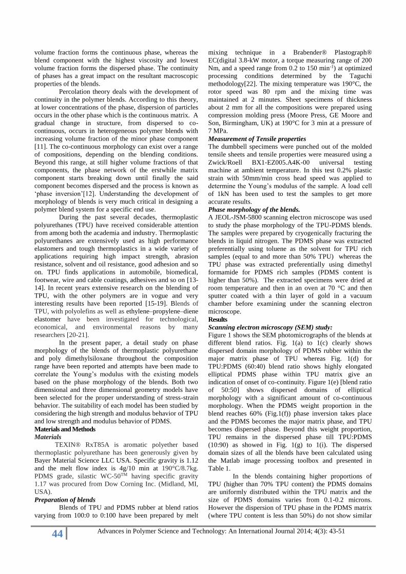
Figure 1 shows the SEM photomicrographs of the blends at
different blend ratios. Fig. 1(a) to 1(c) clearly shows
dispersed domain morphology of PDMS rubber within the
major matrix phase of TPU whereas Fig. 1(d) for
TPU:PDMS (60:40) blend ratio shows highly elongated
elliptical PDMS phase within TPU matrix give an
indication of onset of co-continuity. Figure 1(e) [blend ratio
of 50:50] shows dispersed domains of elliptical
morphology with a significant amount of co-continuous
morphology. When the PDMS weight proportion in the
blend reaches 60% (Fig.1(f)) phase inversion takes place
and the PDMS becomes the major matrix phase, and TPU
becomes dispersed phase. Beyond this weight proportion,
TPU remains in the dispersed phase till TPU:PDMS
(10:90) as showed in Fig. 1(g) to 1(i). The dispersed
domain sizes of all the blends have been calculated using
the Matlab image processing toolbox and presented in
Table 1.
In the blends containing higher proportions of
TPU (higher than 70% TPU content) the PDMS domains
are uniformly distributed within the TPU matrix and the
size of PDMS domains varies from 0.1-0.2 microns.
However the dispersion of TPU phase in the PDMS matrix
(where TPU content is less than 50%) do not show similar
45 Advances in Polymer Science and Technology: An International Journal 2014; 4(3): 43-51
Figure 1. (a) to (e) show the SEM photo micrographs of TPU-PDMS blends from 90:10 to 50:50 ratios etched in toluene.
Figure (f) to (i) show the SEM photo micrographs of TPU-PDMS blends from 40:60 to 10:90 ratio etched with dimethyl
formamide.
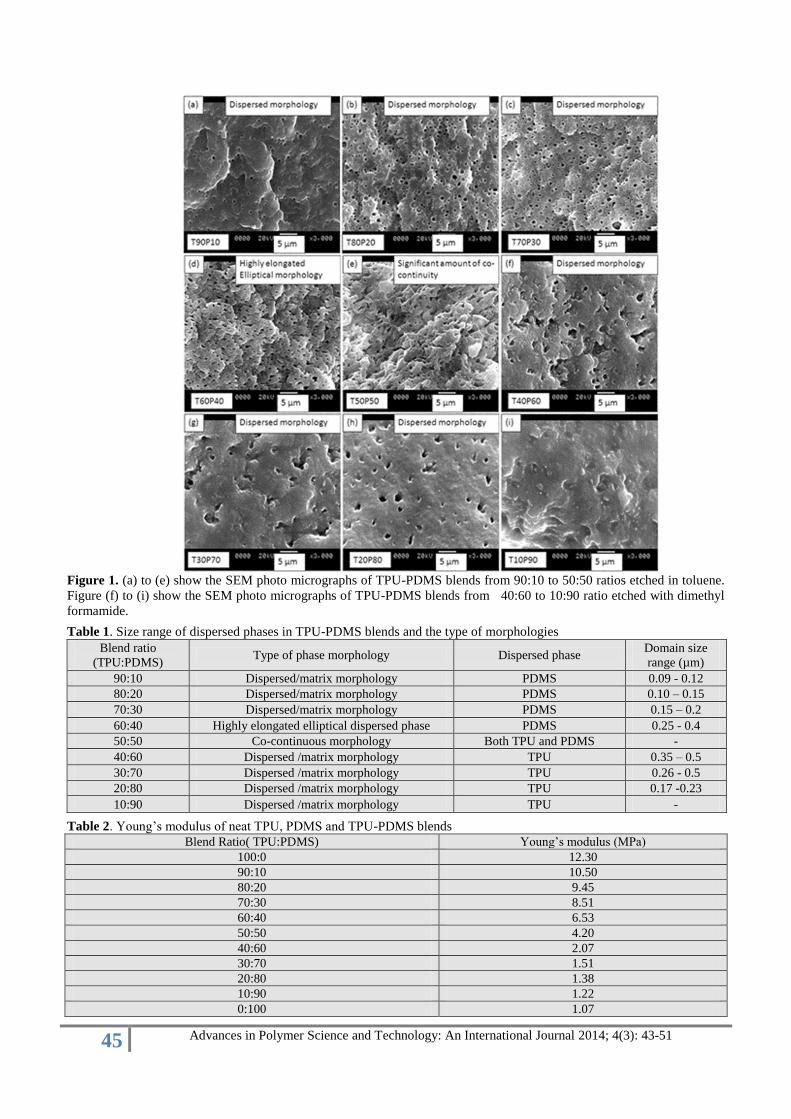
Table 1. Size range of dispersed phases in TPU-PDMS blends and the type of morphologies
Blend ratio
(TPU:PDMS) Type of phase morphology Dispersed phase
Domain size
range (µm)
90:10 Dispersed/matrix morphology PDMS 0.09 - 0.12
80:20 Dispersed/matrix morphology PDMS 0.10 – 0.15
70:30 Dispersed/matrix morphology PDMS 0.15 – 0.2
60:40 Highly elongated elliptical dispersed phase PDMS 0.25 - 0.4
50:50 Co-continuous morphology Both TPU and PDMS -
40:60 Dispersed /matrix morphology TPU 0.35 – 0.5
30:70 Dispersed /matrix morphology TPU 0.26 - 0.5
20:80 Dispersed /matrix morphology TPU 0.17 -0.23
10:90 Dispersed /matrix morphology TPU -
Table 2. Young’s modulus of neat TPU, PDMS and TPU-PDMS blends
Blend Ratio( TPU:PDMS) Young’s modulus (MPa)
100:0 12.30
90:10 10.50
80:20 9.45
70:30 8.51
60:40 6.53
50:50 4.20
40:60 2.07
30:70 1.51
20:80 1.38
10:90 1.22
0:100 1.07
46 Advances in Polymer Science and Technology: An International Journal 2014; 4(3): 43-51
uniformity in the dispersion and the domain sizes of TPU
which fall in the range of 0.5- 1 microns. Interestingly the
TPU:PDMS blend with 10:90 ratio shows a morphology
similar to a single phase matrix with some undulations and
irregularities on the surface because of the etching of TPU.
(Fig. 1(i)).
Mechanical Properties of TPU-PDMS blends
The average Young’s modulus of virgin polymers
and their blends are reported in Table 2. Virgin TPU
exhibits a Young’s modulus of 12.30 MPa and virgin
PDMS exhibits a very low Young’s modulus value of 1.07.
The blends with a dispersed PDMS phase in a TPU domain
matrix show comparatively good mechanical properties.
But as the matrix changes from TPU to PDMS the
mechanical properties are drastically reduced. This is quite
obvious that the major matrix used to take the stress on
elongation during tensile test and when PDMS becomes the
major phase and it can’t take much stress and it lead to a
low tensile strength values.
Study of different models based on dispersed/ matrix
phase morphology
The mechanical properties of the blends depend on
the degree to which they are homogenous. In these blends
two parameters must be defined and they are a) shapes of
the inhomogeneity b) their degree of orientation. As far as
the classical theory of elasticity concerned the dimensions
of the phases present in the blends are irrelevant. But when
higher strains are involved and when yield and fracture
processes are being considered, the dimensions become
very vital. The physical properties of the blends depend
strongly on the phase dimensions.
For modeling the polymer blend system, due
emphasis is being given to Young’s modulus and its
dependence on phase morphology. The importance of
mechanical properties in understanding the behavior of
polymer blends is well understood and the dependence of
mechanical properties on the phase morphology vis-à-vis
processing properties was studied by several authors earlier
[23-26].
Mechanical models have been developed in the
past for understanding the phase behavior, continuity in the
morphology and its effect on mechanical properties of the
polymer blend systems particularly those are heterogeneous
in nature. Predicting the elastic moduli of two-component
systems from the mechanical properties of the individual
components has been the subject of intense investigation.
There has been no general principle based on which this
problem could be solved, but it is certain that moduli are
affected by the morphology of the systems. That is the
juxtaposition and the shape of the individual components in
space, and the way they are bonded together, play a major
role in imparting the physic-mechanical properties. The
basic difficulty always remains a fact that one does not
know the priori, which is how stress and strain are
transmitted through the system [27-32].
Several theories have been propounded to predict
the tensile properties based on various parameters. These
theories are classified into two broad categories: (1) The
theories based on composition and (2) and that based on
morphology [33]. Most of these theories assume perfect
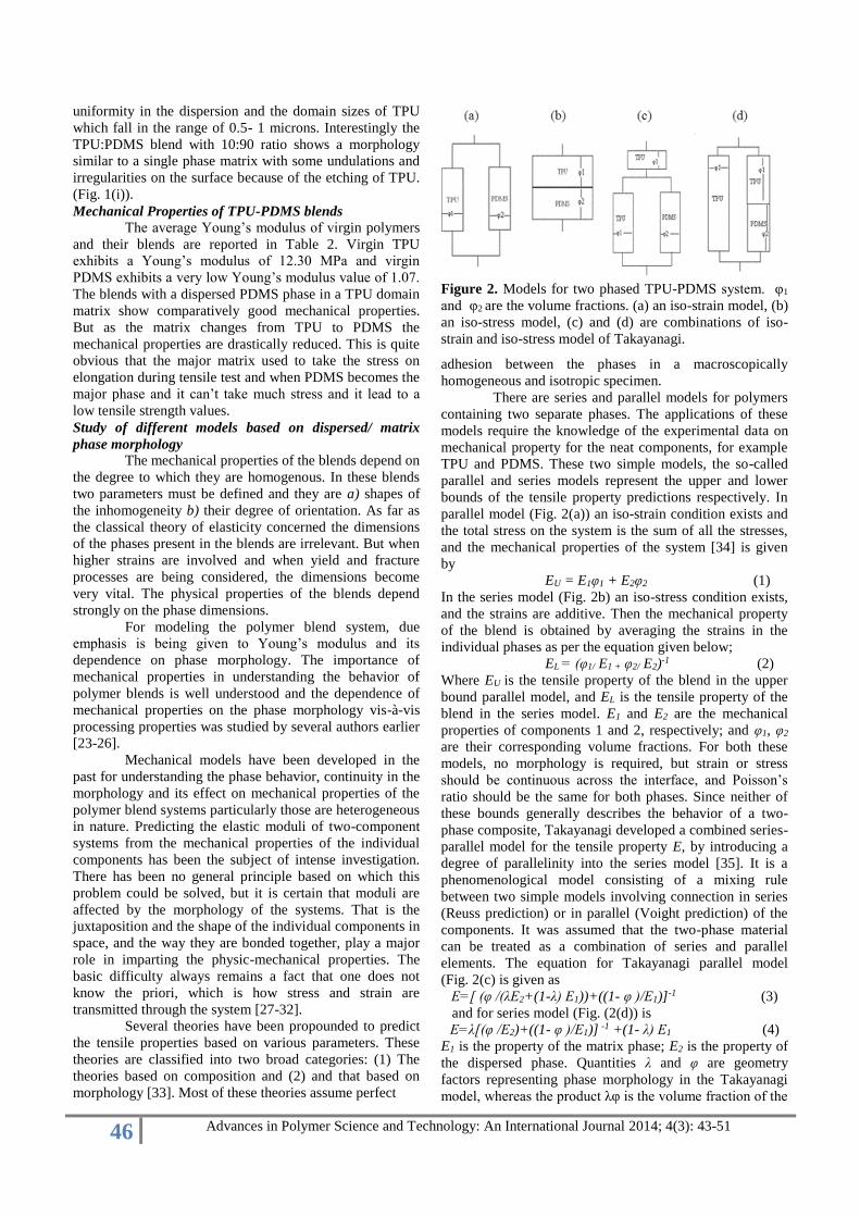
Figure 2. Models for two phased TPU-PDMS system. φ1
and φ2 are the volume fractions. (a) an iso-strain model, (b)
an iso-stress model, (c) and (d) are combinations of iso-
strain and iso-stress model of Takayanagi.
adhesion between the phases in a macroscopically
homogeneous and isotropic specimen.
There are series and parallel models for polymers
containing two separate phases. The applications of these
models require the knowledge of the experimental data on
mechanical property for the neat components, for example
TPU and PDMS. These two simple models, the so-called
parallel and series models represent the upper and lower
bounds of the tensile property predictions respectively. In
parallel model (Fig. 2(a)) an iso-strain condition exists and
the total stress on the system is the sum of all the stresses,
and the mechanical properties of the system [34] is given
by
EU = E1φ1 + E2φ2 (1)
In the series model (Fig. 2b) an iso-stress condition exists,
and the strains are additive. Then the mechanical property
of the blend is obtained by averaging the strains in the
individual phases as per the equation given below;
EL = (φ1/ E1 + φ2/ E2)-1 (2)
Where EU is the tensile property of the blend in the upper
bound parallel model, and EL is the tensile property of the
blend in the series model. E1 and E2 are the mechanical
properties of components 1 and 2, respectively; and φ1, φ2
are their corresponding volume fractions. For both these
models, no morphology is required, but strain or stress
should be continuous across the interface, and Poisson’s
ratio should be the same for both phases. Since neither of
these bounds generally describes the behavior of a two-
phase composite, Takayanagi developed a combined series-
parallel model for the tensile property E, by introducing a
degree of parallelinity into the series model [35]. It is a
phenomenological model consisting of a mixing rule
between two simple models involving connection in series
(Reuss prediction) or in parallel (Voight prediction) of the
components. It was assumed that the two-phase material
can be treated as a combination of series and parallel
elements. The equation for Takayanagi parallel model
(Fig. 2(c) is given as
E=[ (φ /(λE2+(1-λ) E1))+((1- φ )/E1)]-1 (3)
and for series model (Fig. (2(d)) is
E=λ[(φ /E2)+((1- φ )/E1)] -1 +(1- λ) E1 (4)
E1 is the property of the matrix phase; E2 is the property of
the dispersed phase. Quantities λ and φ are geometry
factors representing phase morphology in the Takayanagi
model, whereas the product λφ is the volume fraction of the

47 Advances in Polymer Science and Technology: An International Journal 2014; 4(3): 43-51
dispersed phase and is related to the degree of series
parallel coupling. The degree of series parallel coupling of
the model can be expressed by
% parallel = [φ(1-λ)/(1- φλ)]*100 (5)
Parameters λ and φ vary with composition and with the
change in the state of dispersion. For spherical particles
independently and homogeneously dispersed in a matrix, it
can be assumed that λ is equal to φ.
Figure 3. Barentsen Three-dimensional models for the
calculation of the moduli of dispersed polymer blends (a)
series model of parallel parts (b) parallel model of serial
linked parts.
A combination of parallel and series elements for
three-dimensional geometries in a droplet/matrix blend
system has been proposed by Barentsen[36]. Barentsen’s
model can either be described as a series model of parallel
parts (Fig.3(a) and Eq. (6)) or a parallel model of serial
linked parts (Fig. 3(b) and Eq. (7)). The unit cubes, as
shown in Fig. 3(a) and 3(b), can be used for modeling of
polymer blends with a droplet/matrix morphology when the
dispersed particles are evenly distributed in the matrix.
E=Em[((λ2) Ed+(1- λ2)Em)/((1- λ) λ2Ed+(1- λ2+ λ3)Em)] (6)
E=(1- λ2)Em+[( λ2EmEd)/( λ Em+(1- λ) Ed)] (7)
Where E is the property of the blend according to the
model, Em and Ed are the property of the matrix and
dispersed phase respectively, and the value of λ can be
determined using the equation
λ3= φd =1- φm (8)
where φd and φm are the volume fractions of the dispersed
phase and matrix respectively
Figure 4. Comparison and variation of the theoretically
predicted (based on droplet/matrix morphology) and
experimental Young’s modulus of the TPU-PDMS blends
as a function of volume fraction of the TPU.
Figure 4 shows the comparison and the variation
of the theoretically predicted (based on droplet/matrix
morphology) and experimental Young’s modulus of the
TPU-PDMS blends as functions of volume fraction of the
TPU.
Study of different models based on co-continuous phase
morphology
A co-continuous morphology is a non-equilibrium
morphology that is generated during melt mixing of two
polymers. As such, it is an unstable morphology, and it
starts changing through filament break-up and retraction as
soon as the melt comes out of the mixer. However, the
blend may remain co-continuous, if it is frozen fast. The
co-continuous morphologies are mainly not formed at
single volume fractions, such as the point of phase
inversion, but rather over a range of volume fractions. This
range of volume fractions very much depends upon the
processing conditions and the rheological properties of the
blend components [37]. In particular, in blends with
thermoplastic elastomers (TPEs) co-continuous
morphologies may form over a wider composition range
[38].
s
Figure 5. Three dimensional model for a co-continous
polymer blend (a) – Nijhof series model of parallel parts,
(b) Nijhof parallel model of serial-linked parts
In a co-continuous morphology, the dispersed
phase does not form of separate domains in the matrix
phase, but the so called domains are interconnected
facilitating formation of elongated domains extended
throughout the matrix. To visualize co-continuity, a model
was proposed by Nijhof consisting of three orthogonal bars
of first polymer component embedded in a unit cube where
the remaining volume is occupied by the second polymer
component [39]. Repeating this unit cube in three
dimensional set up shows that first component has the same
framework as the second component, i.e. both the
components are interconnected. Relations for a series
model of parallel parts (Fig. 5(a)) is given in equation 9 and
the relation for parallel model of serial-linked parts (Fig.
5(b)) is given in equation 10.
E=[(a4+2a3b)E12+2(a3b+3a2b2+ab3)E1E2+(2ab3+b4)E2
2]/[
(a3+a2b+2ab2)E1+(2a2b+ab2+b3)E2 (9)
E=[a2bE12+(a3+2ab+b3)E1E2+ab2E2
2]/[bE1+aE2] (10)
Where E1 and E2 are the properties of the first and second
components in the blend respectively, ‘a’ is related to the
volume fraction of first component
3a2-2a3= φ1 (11)
And ‘b’ is related to the volume fraction of the second
component by the equation
48 Advances in Polymer Science and Technology: An International Journal 2014; 4(3): 43-51
b=1-a (12)
The parallel model of serial-linked parts for co-continuity
proposed by Nijhof is comparable to the COS model
proposed by Kolarik [40].
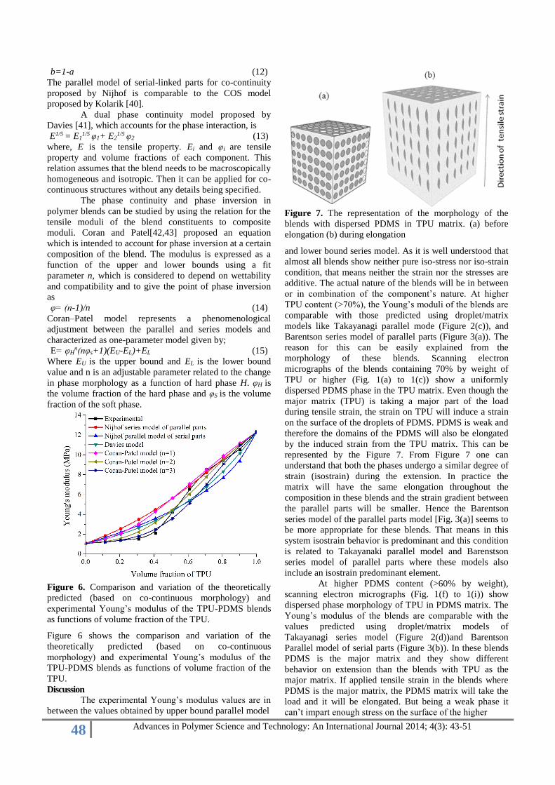
A dual phase continuity model proposed by
Davies [41], which accounts for the phase interaction, is
E1/5 = E11/5 φ1+ E2
1/5 φ2 (13)
where, E is the tensile property. Ei and φi are tensile
property and volume fractions of each component. This
relation assumes that the blend needs to be macroscopically
homogeneous and isotropic. Then it can be applied for co-
continuous structures without any details being specified.
The phase continuity and phase inversion in
polymer blends can be studied by using the relation for the
tensile moduli of the blend constituents to composite
moduli. Coran and Patel[42,43] proposed an equation
which is intended to account for phase inversion at a certain
composition of the blend. The modulus is expressed as a
function of the upper and lower bounds using a fit
parameter n, which is considered to depend on wettability
and compatibility and to give the point of phase inversion
as
φ= (n-1)/n (14)
Coran–Patel model represents a phenomenological
adjustment between the parallel and series models and
characterized as one-parameter model given by;
E= φHn(nφs+1)(EU-EL)+EL (15)
Where EU is the upper bound and EL is the lower bound
value and n is an adjustable parameter related to the change
in phase morphology as a function of hard phase H. φH is
the volume fraction of the hard phase and φS is the volume
fraction of the soft phase.
Figure 6. Comparison and variation of the theoretically
predicted (based on co-continuous morphology) and
experimental Young’s modulus of the TPU-PDMS blends
as functions of volume fraction of the TPU.
Figure 6 shows the comparison and variation of the
theoretically predicted (based on co-continuous
morphology) and experimental Young’s modulus of the
TPU-PDMS blends as functions of volume fraction of the
TPU. Discussion
The experimental Young’s modulus values are in
between the values obtained by upper bound parallel model
Figure 7. The representation of the morphology of the
blends with dispersed PDMS in TPU matrix. (a) before
elongation (b) during elongation
and lower bound series model. As it is well understood that
almost all blends show neither pure iso-stress nor iso-strain
condition, that means neither the strain nor the stresses are
additive. The actual nature of the blends will be in between
or in combination of the component’s nature. At higher
TPU content (>70%), the Young’s moduli of the blends are
comparable with those predicted using droplet/matrix
models like Takayanagi parallel mode (Figure 2(c)), and
Barentson series model of parallel parts (Figure 3(a)). The
reason for this can be easily explained from the
morphology of these blends. Scanning electron
micrographs of the blends containing 70% by weight of
TPU or higher (Fig. 1(a) to 1(c)) show a uniformly
dispersed PDMS phase in the TPU matrix. Even though the
major matrix (TPU) is taking a major part of the load
during tensile strain, the strain on TPU will induce a strain
on the surface of the droplets of PDMS. PDMS is weak and
therefore the domains of the PDMS will also be elongated
by the induced strain from the TPU matrix. This can be
represented by the Figure 7. From Figure 7 one can
understand that both the phases undergo a similar degree of
strain (isostrain) during the extension. In practice the
matrix will have the same elongation throughout the
composition in these blends and the strain gradient between
the parallel parts will be smaller. Hence the Barentson
series model of the parallel parts model [Fig. 3(a)] seems to
be more appropriate for these blends. That means in this
system isostrain behavior is predominant and this condition
is related to Takayanaki parallel model and Barenstson
series model of parallel parts where these models also
include an isostrain predominant element.
At higher PDMS content (>60% by weight),
scanning electron micrographs (Fig. 1(f) to 1(i)) show
dispersed phase morphology of TPU in PDMS matrix. The
Young’s modulus of the blends are comparable with the
values predicted using droplet/matrix models of
Takayanagi series model (Figure 2(d))and Barentson
Parallel model of serial parts (Figure 3(b)). In these blends
PDMS is the major matrix and they show different
behavior on extension than the blends with TPU as the
major matrix. If applied tensile strain in the blends where
PDMS is the major matrix, the PDMS matrix will take the
load and it will be elongated. But being a weak phase it
can’t impart enough stress on the surface of the higher

49 Advances in Polymer Science and Technology: An International Journal 2014; 4(3): 43-51
Figure 8. The representation of the morphology of the
blends with dispersed TPU in PDMS matrix. (a) before
elongation (b) during elongation
modulus TPU matrix to be elongated in the direction of the
strain. This behavior can be represented in the Figure 8.
Here the strains in the both the phases are not similar (no
iso-strain characteristics), Therefore the system is more
similar to the Takayanagi series model and Barentson
Parallel model of serial parts where these models have an
iso-stress predomination.
If the dispersed phase is TPU (blends having less
than or equal to 40% TPU), the matrix will be weak and the
influence of the stiff dispersed phase in the direction
perpendicular to the applied force direction will be limited.
Then according to the model depicted in Fig. 3(b), the stiff
dispersion shall force a part of the weak matrix that is
coupled in series with it to an elongation that is much
longer than the elongation of the rest of the matrix. This is
in agreement with reality because in real blends the weak
matrix in the blend will deform most at the interface
between the stiff droplets and the weak matrix (relative
high strain gradients in the weak matrix do not cost so
much energy). Therefore, the model as depicted in Fig. 3(b)
is more appropriate when the weak PDMS component
dominates. Fig. 4 is in agreement with the above
observation.
The predicted and experimental Young’s moduli
values are completely different in the blends where TPU
content is about 60 & 50% by weight. This is quite obvious
as these blends do not show perfect droplet/matrix
morphology (Fig. 1(d) and 1(e)). T60P40 blend shows a
highly elongated elliptical dispersed PDMS phase in TPU
matrix, and the morphology is intermediate between the
droplet/matrix and is co-continuous. This means the onset
of co-continuous phase formation can be seen in T60P40.
T50P50 shows a significant amount of co-continuity in the
phase morphology. The predicted Young’s moduli for these
two blends are pretty much higher than that of the
experimental values. In these blends, TPU and PDMS are
in co-continuous phase and the applied stress is distributed
through both the matrices. Since the PDMS matrix cannot
withstand high stress as it has low modulus, the blends with
co-continuous morphology exhibit lower Young’s modulus
using the models of droplet/matrix morphology where
PDMS is considered as the dispersed phase.
Co-continuity occurs around the phase inversion
point, where a dispersion of the first component in a matrix
of second component will change into a dispersion of the
second component in a matrix of the first component.
Figure 6 gives comparisons between experimental results
and predicted theory for Young’s modulus obtained with
the aforementioned equations of co-continuity. From
Figure 6 the aforementioned equations cannot give a proper
evaluation of the moduli of the blends over the entire
composition range. From the scanning electron
micrographs, co-continuity is observed in the blend at a
blend ratio of 50:50 and also a highly elongated elliptical
morphology with some onset of co-continuity is observed
in T60P40. The experimental value of T60P40 almost fits
well with the predicted values using the Nihjof Parallel
model of serial linked parts which incorporate the dual
phase interconnectivity. Coran & Patel model also fit well
with a fit parameter n=2.5 which predicts the tensile
strength is closely similar that obtained experimentally for
the T60P40 blend. This value corresponds to VH =0.6 as the
hard phase volume fraction, which corresponds to the phase
inversion of the blends from a dispersed phase to a co-
continuous phase. This observation is in agreement with
our experimental observations from mechanical and
morphological properties. In the micrographs of T60P40,
the transition from droplet/matrix morphology to co-
continuous morphology through the highly elongated
elliptical morphology of the PDMS phase in the TPU
matrix is observed.
Conclusions
A comparison and evaluation between the
experimental results and the theoretically predicted values
based on different developed models for the Young’s
modulus of Thermoplastic Polyurethane and
Polydimethylsiloxane rubber have been presented based on
both droplet/matrix and co-continuous morphology. The
following conclusions may be drawn from the present
study;
1.In the blends where the weak PDMS is uniformly
dispersed in TPU matrix (where TPU content is more than
70%), the matrix will have the same elongation throughout
in these blends, because of the strain imparted by TPU on
the surface of PDMS and the strain gradient between the
parallel parts is small. Therefore the experimental Young’
modulus is similar to the values obtained by Takayanaki
parallel model and Barenstson series model of parallel parts
where these models also include an iso-strain
predomination.
2. In case of the blends where TPU is uniformly dispersed
in the PDMS matrix (where PDMS content is more than
60%), the matrix is weak and the influence of the strain on
the hard dispersed TPU phase in the direction perpendicular
to the applied force direction are limited. Because of this
reason the experimental Young’s modulus of these blends
is in agreement with the theoretical predictions by
Takayanagi series model and Barentson Parallel model of
serial parts where these models are almost similar to this
present condition of these blends.
3. The experimental Young’s modulus of T60P40 fits well
with the theoretical values obtained using the Nihjof
Parallel model of serial linked parts which incorporate the
dual phase interconnectivity even though this blend show
an elongated elliptical morphology with some onset of co-

50 Advances in Polymer Science and Technology: An International Journal 2014; 4(3): 43-51
continuity. Coran& Patel model fit well with a fit parameter
n=2.5 which predicts the tensile strength closely in similar
to that obtained experimentally for the T60P40 blend. This
value corresponds to VH =0.6 as the hard phase volume
fraction, which corresponds to a phase inversion of the
blends from a dispersed phase to a co-continuous phase and
it is in agreement with the scanning electron microscopy
studies.
References
1. D.R. Paul, S. Newman, Polymer blends, vol 2,
Academic Press, New York, 1978.
2. J.G. Bonner, P.S. Hope, Polymer blends and alloys,
Chapman Hall, London, 1993.
3. Y. Wang, Q. Zhang, Q. Fu, Compatibilization of
Immiscible Poly(propylene)/Polystyrene Blends Using
Clay, Macromol. Rapid. Comm. 24 (2003) 231-235.
4. R.J.M. Borggreve, R.J. Gaymans, J. Schuijer, Impact
behaviour of nylon-rubber blends: 4. Effect of the
coupling agent, maleic anhydride, Polymer 30 (1989)
63-70.
5. C.A.P. Joziasse, M.D.C. Topp, H. Veenstra, D.W.
Grijpma, A.J. Pennings Super tough poly(lactide)s.
Polym. Bull. 33 (1994) 599-605.
6. S. Wu, Phase structure and adhesion in polymer
blends: A criterion for rubber toughening, Polymer 26
(1985) 1855-1863.
7. B.Y. Shin, S.H. Jang, I.J. Chung, B.S. Kim,
Mechanical properties and morphology of polymer
blends of poly (ethylene terephthalate) and
semiflexible thermotropic liquid crystalline polyesters,
Polym. Eng. Sci. 32 (1992) 73-79.
8. A.G.C. Machiels, K.J. Denys, J.V. Dam, A.P. de Boer,
Effect of processing history on the morphology and
properties of polypropylene/thermotropic liquid
crystalline polymer blends, Polym. Eng. Sci. 37 (1997)
59-72.
9. H. Verhoogt, C.R.J. Willemse, J.V. Dam, A.P. de
Boer, Blends of a thermotropic LCP and a
thermoplastic elastomer. II: Formation and stability of
LCP fibers. Polym. Eng. Sci. 34 (1994) 453-460.
10. P.M. Subramanian, V. Mehra, Laminar morphology in
polymer blends: Structure and properties, Polym. Eng.
Sci. 27 (1987) 663-668.
11. V.N. Kuleznev, Polymer Mixtures (in Russian),
Khimya, Moskva, 1980.
12. H. Veenstra, J.J. Barbara, J.V. Dam, A.P. de Boer, Co-
continuous morphologies in polymer blends with
SEBS block copolymers, Polymer 40 (1999) 6661-
6672.
13. C. Hepburn, Polyurethane Elastomers, Elsevier
Applied Science, New York, 1992.
14. G. Oertel, Polyurethane Handbook, Hanser, Munich,
1994.
15. B. Zerjal, Z. Jelcic, T. Malavasic, Miscibility in
thermoplastic polyurethane elastomer/poly (styrene-co-
acrylonitrile) blends, Eur. Polym. J. 32 (1996) 1351-
1354.
16. K. Kim, W. Cho, C. Ha, Dynamic mechanical and
morphological studies on the compatibility of
plasticized PVC/thermoplastic polyurethane blends, J.
Appl. Polym. Sci. 71 (1999) 415-422.
17. J. Xie, H. Ye, Q. Zhang, L. Li, M. Jiang, Studies on
polymer blends with moderate specific interactions. 2.
phase structure of blends SAN/TPU and SAN/TPU/
EVA, Polym. Int. 44 (1997) 35-40.
18. G. Kumar, N.R. Mahesh, T.R. Neelakantan, Studies on
thermal stability and behaviour of polyacetal and
thermoplastic polyurethane elastomer blends, Polym.
Int. 31 (1993) 283-289.
19. T. Tang, X. Jing, B. Huang, Studies on
compatibilization of polypropylene/thermoplastic
polyurethane blends and mechanism of
compatibilization, J. Macromol. Sci. Phys. 33 (1994)
287-305.
20. W. Wallheinke, P. Potschke, C.W. Macosko, H. Stutz,
Coalescence in blends of thermoplastic polyurethane
with polyolefins, Polym. Eng. Sci. 39 (1999) 1022-
1034.
21. Q.W. Lu, C.W. Macosko, J. Horrion, Compatibilized
blends of thermoplastic polyurethane (TPU) and
polypropylene, Macromol. Symp. 198 (2003) 221-232.
22. J.A. Gopi, G.B. Nando, Optimization of the processing
parameters in melt blending of thermoplastic
polyurethane and poly dimethyl siloxane rubber, J.
Elastom. Plast. 44 (2012) 189-204.
23. X. Wang, X. Luo, A polymer network based on
thermoplastic polyurethane and ethylene–propylene–
diene elastomer via melt blending: morphology,
mechanical properties, and rheology, Eur. Polym. J. 40
(2004) 2391-2399.
24. B. John, K.T. Varughese, Z. Oommen, P. Po¨tschke, S.
Thomas, Dynamic mechanical behavior of high-
density polyethylene/ethylene vinyl acetate copolymer
blends: The effects of the blend ratio, reactive
compatibilization, and dynamic vulcanization, J. Appl.
Polym. Sci. 87 (2003) 2083-2099
25. B.D. Bliznakov, C.C. White, M.T. Shaw, Mechanical
properties of blends of HDPE and recycled urea-
formaldehyde resin, J. Appl. Polym. Sci. 77 (2000)
3220-3227.
26. U. Nieberall, J. Bohse, S. Seidler, W. Grellma, B.L.
Schurmann, Relationship of fracture behavior and
morphology in polyolefin blends, Polym. Eng. Sci. 39
(1999) 1109-1118.
27. N. Tomar N, S.N. Maiti, Mechanical properties and
morphology of PBT/FE blends, J. Polym. Res. 15
(2008) 37-45.
28. T.S. Chow, Prediction of stress-strain relationships in
polymer composites, Polymer 32 (1991) 29-33.
29. P.H.T. Vollenberg, D. Heikens, Particle size
dependence of the Young's modulus of filled
polymers:Preliminary experiments, Polymer 30 (1989)
1656-1662.
30. T.S. Chow, Effect of particle shape at finite
concentration on the elastic moduli of filled polymers.
J. Polym. Sci. Phys. 16 (1978) 959-965.
31. R.G.C. Arridge, Stresses and displacements in lamellar
composites II, J. Phys. D. Appl. Phys. 9 (1976) 329-
351.
32. S. Boucher, On the effective moduli of isotropic two-
51 Advances in Polymer Science and Technology: An International Journal 2014; 4(3): 43-51
phase elastic composites, J Compos. Mater. 8 (1974)
82-89.
33. Z. Hashin, Analysis of Composite Materials - a survey,
J. Appl. Mech 50 (1983) 481-505.
34. L.E. Nielsen, Mechanical Properties of Polymers and
Composites, 2nd ed., Marcel Dekker Inc, New York,
1974
35. I.M. Ward, Mechanical Properties of Solid Polymers,
2nd ed., John Wilev, New York, 1983.
36. W.M. Barentsen WM, Ph.D Thesis, Eindhoven
University of Technology, The Netherlands, 1972
37. H. Veenstra, J.V. Dam, A.P de Boer, Formation and
stability of co-continuous blends with a poly (ether-
ester) block copolymer around its order–disorder
temperature, Polymer. 40 (1999) 1119-1130.
38. H. Verhoogt, J.V. Dam, A.P. de Boer, Morphology-
processing relationship in interpenetrating polymer
blends Styrene-Ethylene/Butylene-Styrene block
copolymer and Poly (ether ester), Adv. Chem. Ser. 239
(1994) 333-351.
39. A.H.J Nijhof, LTM-report 1167, Delft University of
Technology, The Netherlands, 1998
40. J .Kolařík, Three-dimensional models for predicting
the modulus and yield strength of polymer blends,
foams and particulate composites, Polym. Composite
18 (1997) 433-441.
41. W.E.A. Davies, The theory of elastic composite
materials, J. Phy. D. Appl. Phys. 4 (1971) 1325-1338.
42. A.Y. Coran, R. Patel, Predicting elastic moduli of
heterogeneous polymer compositions, J. Appl. Polym.
Sci. 20 (1976) 3005-3016.
43. A.Y. Coran, R. Patel, Rubber-thermoplastic
compositions. Part VII. Chlorinated polyethylene
rubber nylon compositions, Rubber Chem. Technol. 56
(1983) 210-225.
Source of support: Nil; Conflict of interest: None declared