ISSN : 2277-5633 (Online) Indian Journal of Geosynthetics and Ground Improvement€¦ · ·...
48
Vol. 1 • Part 1 • January 2012 Half Yearly Technical Journal of Indian Chapter of International Geosynthetics Society Half Yearly Technical Journal of Indian Chapter of International Geosynthetics Society Indian Journal of Geosynthetics and Ground Improvement Indian Journal of Geosynthetics and Ground Improvement Indian Journal of Geosynthetics and Ground Improvement Indian Journal of Geosynthetics and Ground Improvement ISSN : 2277-5625 (Print) ISSN : 2277-5633 (Online)
Transcript of ISSN : 2277-5633 (Online) Indian Journal of Geosynthetics and Ground Improvement€¦ · ·...

Vol. 1 • Part 1 • January 2012
Half Yearly Technical Journal of Indian Chapter of International Geosynthetics Society
Half Yearly Technical Journal of Indian Chapter of International Geosynthetics Society
Indian Journal of Geosynthetics and Ground Improvement
Indian Journal of Geosynthetics and Ground Improvement
Indian Journal of Geosynthetics and Ground Improvement
Indian Journal of Geosynthetics and Ground Improvement
ISSN : 2277-5625 (Print)ISSN : 2277-5633 (Online)

ABOUT JOURNAL
Geosynthetics are now being increasingly used the world over for every conceivable applicationin civil engineering, namely, construction of dam embankments, canals, approach roads, runways,railway embankments, retaining walls, slope protection works, drainage works, river training works,seepage control, etc. due to their inherent qualities. Its use in India though is picking up, is not anywhere close to recognitions. This is due to limited awareness of the utilities of this material anddevelopments having take place in its use.
The aim of the journal is to provide latest information in regard to developments taking place in therelevant field of geosynthetics so as to improve communication and understanding regarding suchproducts, among the designers, manufacturers and users and especially between the textile andcivil engineering communities.
EDITORIAL BOARD
• Dr. K. Balan, Professor, Department of Civil Engineering, College of Engineering, Trivandrum
• Mr. Narendra Dalmia, Director, Strata Geosystems (India) Pvt. Ltd.
• Mr. S. Jaswant Kumar, Chief General Manager, National Highways Authority of India
• Ms. Minimol Korulla, Maccaferri Environmental Solutions Pvt. Ltd.
• Dr. Satyendra Mittal, Associate Professor, Department of Civil Engineering, Indian Institute of TechnologyRoorkee
• Mr. Satish Naik, CEO, Best Geotechnics Pvt. Ltd.
• Dr. K. Rajagopal, Professor, Department of Civil Engineering, IIT Madras
• Dr. G.V.S. Raju, Chief Engineer (R&B), Govt. of Andhra Pradesh
• Dr. G.V. Rao, Chairman, SAGES
• Ms. Dola Roychowdhury, Senior General Manager (Geosynthetics Division), Z-Tech (India) PrivateLtd.
• Mr. T. Sanyal, Chief Consultant, National Jute Board
• Dr. U.S. Sarma, Director, Coir Board
• Dr. B.V.S. Viswanadham, Professor, Department of Civil Engineering, Indian Institute of TechnologyBombay

CONTENTSPage No.
FROM EDITOR’S DESK 2• Jute Fibres for Geosynthetics – Strategies for Growth – Dr. G.Venkatappa Rao, (Mrs.) G.Anuradha 3
• Bearing Capacity of Foundations on Geosynthetic Reinforced Foundation Beds on SoftNon-Homogeneous Ground – K. Rajyalakshmi, Madhira R. Madhav, K. Ramu 11
• Centrifuge Model Studies on the Performance of Geogrid Reinforced Soil Barriers ofLandfill Covers – S. Rajesh, B.V.S. Viswanadham 20
• Effect of Geogrid in Saturated Sand against Liquefaction - Rajiv Chauhan 29
• Behaviour of Geocell in Cohesionless Soil – An Experimental Study – Sefali Biswas 30
• Calendar of Events 31
• Report on R&D Activities Related to Jute Geotextiles (JGT) – Tapobrata Sanyal 32
• International Geosynthetics Society 33
• International Geosynthetics Society (India) 36
• Activities of Indian Chapter of IGS – Seminar on “GEOSYNTHETICS INDIA’ 11”22-24 September 2011, IIT Madras 40
• IGS News 44
INDIAN CHAPTER OF INTERNATIONAL GEOSYNTHETICS SOCIETY
Indian Journal of Geosynthetics andGround Improvement
Volume 1, No. 1 January 2012
All communications to be addressed to :The Member SecretaryIndian Chapter of IGSCBIP Building, Malcha Marg,Chanakyapuri, New Delhi – 110 021

2 Indian Journal of Geosynthetics and Ground Improvement
Volume 1 v No. 1 v January 2012
FROM THE EDITOR’S DESK
In the year 1985, Central Board of Irrigation and Power, (CBIP) as part of its technologyforecasting activities identified geosynthetics as an important area relevant to India’sneed for infrastructure development, including roads.
Since the approval of IGS Council for the formation of Indian Chapter in October1988, the Chapter has been involved in collection, evaluation and dissemination ofknowledge on all matters relevant to geotextiles, geomembranes and related syntheticand natural materials
Geosynthetics are now being increasingly used the world over for every conceivable application in civilengineering, namely, construction of dam embankments, canals, approach roads, runways, railwayembankments, retaining walls, slope protection works, drainage works, river training works, seepage control,etc. due to their inherent qualities. Its use in India though is picking up, is not anywhere close to recognition.This is due to limited awareness of the utilities of this material and developments having take place in itsuse.
As part of the activities of Indian Chapter, the first issue of its Technical Journal, Indian Journal of Geosyntheticsand Ground Improvement, is in your hands. The Journal will be published on half yearly basis (January –June and July-December), both print and online versions.
The aim of the journal is to provide latest information in regard to developments taking place in therelevant field of geosynthetics so as to improve communication and understanding regarding such products,among the designers, manufacturers users especially from the textile and civil engineering communities.
I thank all the authors for their contributions. I also take this opportunity to thank all the members of theEditorial Board for helping us in our endeavour and providing us with their valuable suggestions in bringingout the Journal.
I request all the readers who are interested for publishing their technical paper/article, views, etc., in thesubsequent issues of the journal, to contribute at the earliest.
I also request for the comments/suggestions of the readers so as to improve the utility of the Journal.
V.K. KanjliaMember Secretary
Indian Chapter of IGS
2

3
Volume 1 v No. 1 v January 20123
Natural fibres such as jute were the forerunners of theman-made fibres used for centuries for making ropes andfor manufacturing burlaps, sacks, Hessian and carpetbacking. The Ziggurat, (which is part of the Aqar-quf,about 25 km from Baghdad, believed to be built in the16th century B.C. by the Kassites,) standing presently 57m high (original height was thought to be 78 m), wasbuilt from clay and reinforced by reed matting. Ropeanchors comprising of 3 bundles of straw each of 25 mmdiameter were installed (Dikran et al 1996). Ingeotechnical engineering isolated uses are recorded suchas the trials undertaken in Dundee (UK) in the 1920’swhere jute burlap was used under some sections of anewroad on poor subgrade (UNCTAD/GATT, 1986). Jutemesh was probably first used in erosion control andhighway side-slope protection in the U.S.A. in early1930’s. According to UNCTAD/GATT (1985,1986), jutenets have been used in for over twenty years in the U.S.A.with an annual consumption of 3, 000 t.
THE INTERNATIONAL BACKGROUND
Currently the production of the jute fibre in India is around100 lakh bales and about 73 jute mills are operating inthe country. Besides, there are several small scaleindustries in the decentralized sector producinghandicrafts, decorative, twines, pulp & paper from juteand allied fibers and particle board from jute stick. Asper the latest Exim Bank report on the Jute industry, theworld market for geotextiles, currently dominated bysynthetics is over 40 million sq. m. Immense potentialalso exists in the USA and Europe.
As per the International Geosynthetics Society(IGS,2000), a Geosynthetic is a planar, polymeric (syntheticor natural) material used in contact with soil/rock and/or
any other geotechnical material in civil engineeringapplications. Similarly a geotextile , a geomembrane andgeocell are described as containing polymeric – syntheticor natural materials. On the other hand, ASTM (1997)defines a Geosynthetic,(n) as a planar productmanufactured from polymeric material used with soil,rock, earth, or other geotechnical engineering relatedmaterial as an integral part of a man-made project,structure or system. But by general nature of testing ofprocedures specified by ASTM, it could imply that theGeosynthetic could be only of synthetic polymers.According to the doyen of Geosynthetics technology,Professor Robert Koerner (1998) “— term Geo, of course,refers to earth. Acknowledgement that the materials ofare almost exclusively from human-made products givesthe second part to the name – synthetics. The materialsused in the manufacture of Geosynthetics are almostentirely from the plastics industry; that is they are primarilypolymers, although fiberglass, rubber, and naturalmaterials are sometimes used.” Thereby his classic book‘Designing with Geosynthetics’ (4th edn. 1998) does notdeal with Geosynthetics made of natural fibres such asjute and coir (co-conut fibre) which were considered asbiodegradable. Giroud (1984) opines that “Natural fibresare very seldom used to make Geotextiles because theyare biodegradable. Geotextiles made from natural fibresand even paper, may however, serve temporary functionswhere biodegradation is desirable (e.g., Temporaryerosion control).The Fibre CharacteristicsJute, a bast fibre (coming from the stem of the plant, byretting process), has a tenacity of around 30 cN/tex witha low extension at break of around 1.6 to 3.8%. Thetenacity of coir fibres (coming from the husk of thecoconut, retted or unretted – white coir or brown coir
JUTE FIBRES FOR GEOSYNTHETICS –STRATEGIES FOR GROWTH
Dr. G. Venkatappa RaoDistinguished Professor, KL University, Vijayawada, Andhra Pradesh and
Chairman, Sai Master Geoenvironmental Services Pvt Ltd.
(Mrs.) G. AnuradhaDirector, Sai Master Geoenvironmental Services Pvt Ltd, Hyderabad
Abstract : While the use of jute in packaging, home décor etc. is well known, the use of jute in geotextilesis a largely unexplored area although it can offer vast benefits to the indigenous industry and agri-economyoverall. The vast amount of research and development conducted on jute geotextiles (JGT) over the yearshas been briefly highlighted. In previous studies conducted on JGT, the emphasis was frequently onassessing the suitability of a particular type of JGT for a specific application. This paper proposes a shiftin approach; from that of a Supply chain bringing together all the stakeholders to a Demand network usinginformation systems. This will add ‘value’ to JGT and help them move up the value chain thus increasingprofitability for all stakeholders and also be socially and environmentally sustainable.
HISTORICAL

4 Indian Journal of Geosynthetics and Ground Improvement
Volume 1 v No. 1 v January 2012
respectively) is much lower 15 cN/tex, but elongation atbreak is much higher, around 40 %. The growth of micro-organism on vegetable fibres depends on their chemicalcomposition, particularly the lignin content. Coir hasabout 35 % lignin content, making it extremely resistingagainst biodegradation, whereas for jute it is only around12 %. The other bast fibres like flax, hemp and ramiehave much low quantity of lignin (0.6 to 3.3 %).
Biodegradability Quantified
To address the question of biodegradability, extensivestudies have been conducted at IIT Delhi over manyyears. Figure 1(a) illustrates the decay of the jute type Aand type B, in Fig. 1 (b) under differential environmentalconditions. It is evident the loss in strength is much slowerin saturated clay conditions and the fastest with manure.Also the degradation is much slower for heavier fabrictype (a). The scanning electron micrographs presentedin Fig.2 also indicate the extent of degradation in thestructure of the fibre in manure with sand. Why the fabriclost its strength totally after 24 days is evident from thetotal decay of the fibre.
Fig. 1(b) : Loss in strength for Jute fabric type (b) underdifferent environmental conditions
Fig. 1(a) : Loss in strength for Jute fabric type (a) underdifferent environmental conditions.
(a) In sand at a water contant of 12% (Admixture Y)(b) In clay at a water content of 45%, i.e., above its
plastic limit value (Admixture K)(c) Sand mixed with manure in equal proportion (1:1)
at a water content of 20% (Admixture Y1)(d) Clay mixed with manure in equal proportion
(1:1:1) at a water content of 50% (Admixture K1)(e) Sand mixed with clay and manure in equal
proportion (1:1:1) at a water content of 30%(Admixture YK1)
(f) Garden soil having an organic content of 8% at awater content of 30% (Admixture G)
Fig. 2 : Scanning electron micrographs of jute (a) fresh jute, (b)after 14 days in admixture Y1 (c) after 24 days in admixture Y1.

5
Volume 1 v No. 1 v January 2012
Testing and Evaluation of Jute Geotextiles
Significant work has been done while the author was IITDelhi to evaluate the physical and engineeringcharacteristics of coir and jute geotextiles for groundimprovement and RECPs. The details are now availablein Venkatappa Rao et al (2009). The Bureau of IndianStandards has now brought out the Standard TestProcedures specifically for Jute and coir Geotextiles (IS15868 – Parts 1 to 6- 2008).
Action Points
The test methods and related equipment need to bepoularized in our country. Also the evaluation processesof jute Geotextiles need to be strengthened, as there isno agency to certify product being suitable for a givenapplication.
Erosion Control – The Classical Application
As already mentioned earlier, the natural fibre productshave long been known to serve erosion control, arisingfrom natural processes of forest cover etc. to minimizethe movement of soil cover, through vegetative cover. Itis interesting to note that the first product to come outsince British days in India was designated as SOILSAVER, and probably first produced from Ludlow Mills,Calcutta. This was basically made of jute caddies ( awaste by product of jute fibre) and till recently the onlytype of geojute being marketed. Subsequent yeomanwork of IJIRA, along with inputs from NIRJAFT and IJT,and through encouragement of JMDC several newproducts are being developed, but they need the test oftime.
jute caddies) was – grade 500 gsm, strand thickness 5mm and open area – 65 %.
Sanyal (1992) has reported the successful use of geojutewith mangroves planted in the interspaces for protectionof eroding banks of Nayachara island in the Hugli estuary.The product used is a bitumenised jute fabric (base fabric– D.W.twill 850 gsm with bitumen application of 80 %base weight).
In the U.S.A. the Erosion Control Technology Council(ECTC, 2001) has developed classifications of RolledErosion Control products as follows :
Erosion Control Nets (ECNs) –temporary, degradableplanar woven natural fibre or extruded Geosyntheticmeshes used to anchor loose fibre mulches
Open Weave textiles (OWTs) – temporary, degradableRECPs composed of processed natural or polymer yarnswoven into a matrix, used to provide erosion control andfacilitate vegetation establishment
Erosion Control blankets (ECBs) – temporary, degradableRECPs composed of natural or polymer fibres that aremechanically, structurally, or chemically bound togetherto form continuous matrices
Turf Reinforcements mats (TRMs) long term non—degradable ones with synthetics fibres.
In India one calls OWTs as Erosion Control Meshes.Smith et al (2006) have carried extensive studies on theproperties of of various types of RECBs available in Indiaand overseas and brought out significant usefulinformation.
Action Points
It is required that our products go through evaluation asdetailed in Smith et al (2006) and subject them toappropriate classification, if one has to cater to the USand other International markets. Also, the QC/QAprocedures need to be followed.
For Indian markets, field data needs to be obtained toidentify the correct product to suit the climate, topographyand soil conditions at various locations all over India.
Jute Fibre Drains
Pre-consolidation of soften soils is often aided by theinstallation of prefabricated vertical drains (PVD). Wideranges of PVDs, made of synthetic polymers are beingcommercially. In view of the fact that natural fibres areavailable in abundance in southeast Asia, a drain producedentirely from jute and coir were first developed byRamaswamy and co-workers as reported in Lee et al (1989)and Lee et al (1994).The fibre drain primarily consisted offour coir yarns for transporting water enveloped by two-layers of jute burlap (jute Hessian cloth) acting as a filter.These are held together by three longitudinal stitches. This
Fig. 3 : The first jute geotextile (Soil Saver) made primarilyusing jute caddies (Ca 1940)
Juyal and Dadhwal (1996) working at the Central Soiland Water Conservation Research and Training Institute,Dehradun, have reported successful use of geojute tore-vegetate the highly erodible steep mine spoil slopesat Sahasradhara. The product used (probably made from
Jute Fibres for Geosynthetics – Strategies for Growth

6 Indian Journal of Geosynthetics and Ground Improvement
Volume 1 v No. 1 v January 2012
drain developed in Singapore is 80 to 100 mm wide and 8 to10 mm thick. This strong and heavy drain has dry strengthof about 5 to 7 kN and weighs about 3000 to 3400 g/sq m.Successful field trials at Bhishan depot were also reportedby them, for Singapore mass rapid transit system forstabilizing highly compressible water logged peaty soils.Following this the IJIRA developed a similar productreplacing the coir yarns with jute yarns of 10 mm diameter.It consisted of 4 jute yarns surrounded by two layers of juteburlap and is 110 mm wide and 15 mm thick. Model studiesreported by Venkatappa Rao et al (1994) have revealed itsperformance as satisfactory. Subsequently, the author(Venkatappa Rao and Balan,1997) developed a fewvarieties of natural fibre drains with jute burlap as the sheathand coir web for water flow capacity and reported dischargecapacity measurements, through a new drain tester.
A simple machine has been developed at TextileTechnology Department of IIT Delhi (Banerjee, 1996,Banerjee et al, 2000) that uses coir and jute yarns tomanufacture 100 % natural fibre strip drains. Themachine employing braiding technology (shown in Fig.4) braids jute yarns to form the filter sheath and coir yarnas core. Typically the drains, as depicted in Fig. 5 areabout 7.5 mm to 12.5 mm thick in dry state and have atensile strength of 3 kN. The properties of the drain havebeen studied in comparison with two synthetic drains andanother type of natural fibre strip drain (Venkatappa Raoet al, 2000). In general, the properties of the drain arefound to be comparable with typical synthetic drains,except that for a slightly lower discharge capacity undersoil confinement. An important feature of the jute yarnsheath is its swelling nature that allows it to function asfilter without clogging. The present drain differs from theother natural drain is that it is manufactured in a singlemachine, and has capability of varying the width,thickness and weight per linear metre to suit differentsoil conditions.
Fig. 5 : Braided strip drain (Brecodrain) with jute and coir yarns.
Action Points
All the drains described above despite their provenlaboratory performance, are yet to be field tested. This,of course, calls for a modification in the mandrel that isnecessary for installation of the drains. It is also pertinentto note that as the drain is much thicker and heavier thanthe synthetic one, may require a larger driving force whichin turn may call for higher strength, due its higherpenetration resistance.
Applications in Roads on Soft Soils
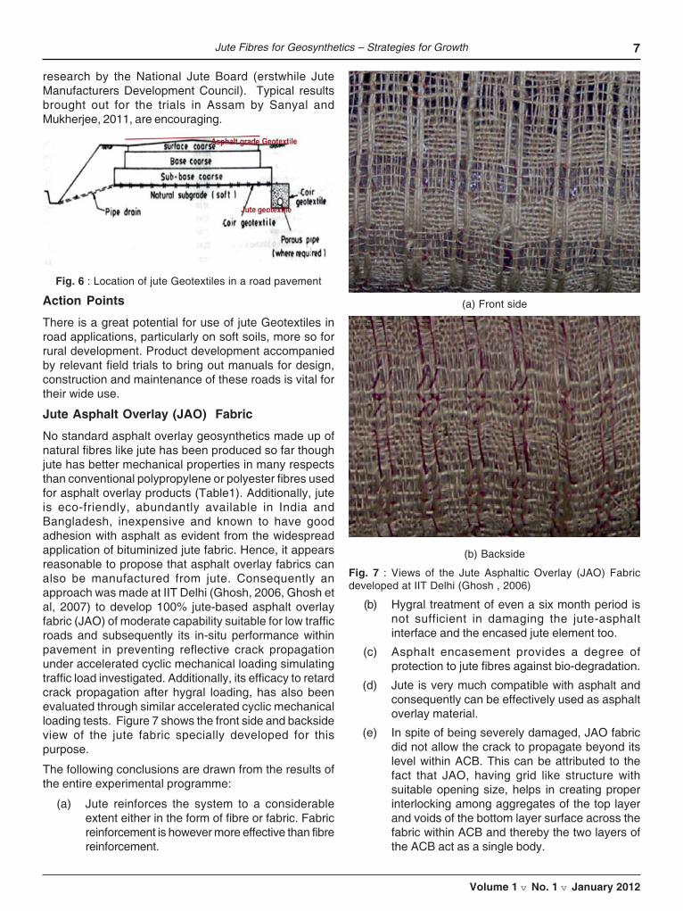
Considerable work has been done by Ramaswamy andco-workers (Ramaswamy and Aziz, 1989) to demonstratethat jute geotextile has the potential of being used to serveas a filter fabric as well a fabric reinforcement to stabilizeand protect weak sub-grades in road construction. It iswell brought out that in course of time i.e. in the first 6 to10 months of construction the soil may stabilize yieldinga better CBR value, thereafter the decay in the jute fabricis not a concern. Figure 6 shows the possible positioningof jute Geotextiles in a road pavement structure. havesuccessfully used jute Geotextiles in many projects forseparation, drainage etc.
A pilot project on JGT was undertaken under PMGSYprogramme in 2006 with the support and approval of theUnion Ministries of Rural Development and Textiles inten stretches spread over five states of Assam,Chattisgarh, Madhya Pradesh, Orissa and West Bengalcovering a total length of around 48 km. The Central RoadResearch Institute, New Delhi was entrusted with this fieldFig. 4 : Braiding machine developed at IIT Delhi to manu-
facture Brecodrain
7
Volume 1 v No. 1 v January 2012
research by the National Jute Board (erstwhile JuteManufacturers Development Council). Typical resultsbrought out for the trials in Assam by Sanyal andMukherjee, 2011, are encouraging.
(b) Hygral treatment of even a six month period isnot sufficient in damaging the jute-asphaltinterface and the encased jute element too.
(c) Asphalt encasement provides a degree ofprotection to jute fibres against bio-degradation.
(d) Jute is very much compatible with asphalt andconsequently can be effectively used as asphaltoverlay material.
(e) In spite of being severely damaged, JAO fabricdid not allow the crack to propagate beyond itslevel within ACB. This can be attributed to thefact that JAO, having grid like structure withsuitable opening size, helps in creating properinterlocking among aggregates of the top layerand voids of the bottom layer surface across thefabric within ACB and thereby the two layers ofthe ACB act as a single body.
Fig. 6 : Location of jute Geotextiles in a road pavement
Action Points
There is a great potential for use of jute Geotextiles inroad applications, particularly on soft soils, more so forrural development. Product development accompaniedby relevant field trials to bring out manuals for design,construction and maintenance of these roads is vital fortheir wide use.
Jute Asphalt Overlay (JAO) Fabric
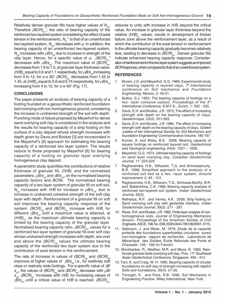
No standard asphalt overlay geosynthetics made up ofnatural fibres like jute has been produced so far thoughjute has better mechanical properties in many respectsthan conventional polypropylene or polyester fibres usedfor asphalt overlay products (Table1). Additionally, juteis eco-friendly, abundantly available in India andBangladesh, inexpensive and known to have goodadhesion with asphalt as evident from the widespreadapplication of bituminized jute fabric. Hence, it appearsreasonable to propose that asphalt overlay fabrics canalso be manufactured from jute. Consequently anapproach was made at IIT Delhi (Ghosh, 2006, Ghosh etal, 2007) to develop 100% jute-based asphalt overlayfabric (JAO) of moderate capability suitable for low trafficroads and subsequently its in-situ performance withinpavement in preventing reflective crack propagationunder accelerated cyclic mechanical loading simulatingtraffic load investigated. Additionally, its efficacy to retardcrack propagation after hygral loading, has also beenevaluated through similar accelerated cyclic mechanicalloading tests. Figure 7 shows the front side and backsideview of the jute fabric specially developed for thispurpose.
The following conclusions are drawn from the results ofthe entire experimental programme:
(a) Jute reinforces the system to a considerableextent either in the form of fibre or fabric. Fabricreinforcement is however more effective than fibrereinforcement.
(a) Front side
(b) Backside
Fig. 7 : Views of the Jute Asphaltic Overlay (JAO) Fabricdeveloped at IIT Delhi (Ghosh , 2006)
Jute Fibres for Geosynthetics – Strategies for Growth

8 Indian Journal of Geosynthetics and Ground Improvement
Volume 1 v No. 1 v January 2012
(f) The opening size of the grids of an asphalt overlayfabric should be compatible with the largeraggregates of the AC mix used in pavement sothat those particles can pass easily through theopenings of the grid without causing significantdamage to the fabric.
The Future
Currently the production of the fibre in India is around 100lakh bales and about 73 jute mills are operating in thecountry. As per the latest Exim Bank report on the Juteindustry, the world market for geotextiles, currentlydominated by synthetics is over 40 million sq. m.Immense potential also exists in the USA and Europe.The report summarizes the present drawbacks of theIndian Jute industry. As availability of raw jute dependson the vagaries of nature, there is instability in the supplyand price of jute. Till grether and Haldia (2003) haverightly mentioned that not enough is being done by thejute industry into production of new products. Accordingto them, this may also lead to:
- Price of fibres may fall making it unattractive for thefarmers, who may diversify into other cash crops
- As the farmers have no core material for fuel or petrol,they may start denuding the forest wealth, which furtheradds to soil erosion and ultimately effecting climaticchanges.
A lack of standardization and indifference to specificationshas led to stagnation of the market. Greater emphasison production and lack of professional marketing hascaused deeper erosion of markets by synthetics. Highlabour costs, accounting for nearly 35% of the cost ofthe production (partly owing to absence of majortechnological breakthrough), has made jute cultivationenergy inefficient and less lucrative compared to othercrops. Excessive dependence on packaging industry hasmade jute synonymous with “gunny bags”, thus leadingto a perception problem. As a result, Jute is not able toattract new investment and has limited global productionbase. Apart from this, there is another common perceptionthat the industry provides low financial return. Thereappears to be deficient attention to consumer preferencesthat has resulted in mismatch between predictingconsumer’s needs with respect to quality of fabric,bleaching, printing and designs.
Jute Geotextiles were identified by the industry andgovernment as a focus area is offering major potentialfor all the stakeholders. Some promotional activities havebeen undertaken; however the future of Jute Geotextilesis also affected by the above problems which affect thejute industry as a whole.
For the above drawbacks, Venkatappa Rao andAnuradha (2008) proposed some technology based
marketing strategies, which are briefly highlightedherein.
Review of research and developments, and use in Indiaclearly points out that the potential is high for juteGeotextiles to find a prominent place amongstGeosynthetics. A recent publication by the National JuteBoard titled JUTE GEOTEXTILES (2011) an anthologyof papers on study, development and applications of JuteGeotextiles, is a comprehensive document. But muchmore needs to be done to bring them on par withsynthetics – in terms of competitive product developmentand quality manufacture. There is a unique place fornatural fibre products in limited applications. But thenjute has to establish the market competitiveness withother natural fibre products even in India.
Marketing Strategies
Greater emphasis on production and lack of professionalmarketing has caused deeper erosion of markets bysynthetics. High labour costs, accounting for nearly 35%of the cost of the production (partly owing to absence ofmajor technological breakthrough), has made jutecultivation energy inefficient and less lucrative comparedto other crops. Excessive dependence on packagingindustry has made jute synonymous with “gunny bags”,thus leading to a perception problem. As a result, Jute isnot able to attract new investment and has limited globalproduction base. Apart from this, there is another commonperception that the industry provides low financial return.There appears to be deficient attention to consumerpreferences has resulted in mismatch between predictingconsumer’s needs with respect to quality of fabric,bleaching, printing and designs. Jute Geotextiles (JGT)have been identified by the industry and government asa focus area is offering major potential for all thestakeholders. Some promotional activities have beenundertaken, however the future of JGT is also affectedby the above problems which affect the jute industry asa whole.
For the above drawbacks, this some technology basedmarketing strategies are now proposed. Using the popularAnsoff’s Product/Market Expansion Grid (Fig. 8), as astarting point, one notes that with the currently availableJGT products, there are two strategies available :
– Market penetration strategy, and
– Market-development strategy.
Current products New Products
Current 1. Market penetration 3. Productmarkets strategy development strategy
New 2. Market-development (Diversificationmarkets strategy strategy)
Fig. 8: Ansoff’s Product/Market Expansion Grid

9
Volume 1 v No. 1 v January 2012
Market Penetration Strategy
There are three major approaches to increasing currentproducts’ market share: The producers/productioncompanies can create more awareness about the benefitsof JGT and thus encourage users to increase the purchasequantity. For this, the producers also need to educate theirmarketing personnel about the technical properties andbenefits of their products to avoid selling merely on price.Two, they could try to attract competitors’ consumers (inthis case say, consumers of synthetic geotextiles) by tryingto identify weaknesses in the competitor’s products. Finally,they could try to convince non-users of JGT.
Market Development Strategy
This can again be done in three broad ways. First, newpotential user groups can be identified. Second, additionaldistribution channels may be sought in present locations.Third, new consumer locations across the world may beidentified for selling.
Product Development Strategy
In addition to penetrating and developing markets,managements should consider new-product possibilities.Identifying opportunities higher up the value chain, wouldnot only avoid the ‘commodity’ perception of JGT, it willalso yield higher profits. Varying quality levels could beconsidered depending on the application in question.Prices of most of agricultural commodities show a long-term declining trend. Increasingly markets are signalingdemand for differentiated products and in order toincrease their incomes. Farmers and traders are lookingto higher value options, including differentiated products.Product differentiation occurs when a product offering isperceived by the consumer to differ from its competitionon any physical or non-physical characteristic includingprice. The differentiation can be based both on perceptualdifferences and also on actual product differences, basedon measurable characteristics.
While developing new products, it is crucial to take intoconsideration, the consumer adoption process. Adoption isan individual’s decision to become a regular user of a product.
Stages in the Adoption Process of an Innovation/New Product
This simple model focuses on the mental process throughwhich an individual passes from first hearing about aninnovation to final adoption.
Awareness – Interest – Evaluation – Trial – Adoption.
At each step, marketers need to take appropriatemeasures to ensure the consumers move on to finaladoption, e.g., free samples or trial periods are introducedto enable the consumer to evaluate and try the productsbefore making a bulk purchase.
Paradigm Shift
Taking into consideration that JGT are generic materials,and that based on the application, the technicalspecifications vary greatly, a paradigm shift from currentmarketing practices is necessary to leverage the threeintensive growth strategies stated above. So far, in theJGT development process and jute industry as a whole,a broad supply chain model is at work.
A supply chain (Fig. 9) is the system of organizations,people, technology, activities, information and resourcesinvolved in transforming natural resources to develop aproduct or service and move it from supplier to customer.
Fig. 9 : A diagram of a supply chain
Fruit exports worldwide, which have directly impacted ourlives by the creation a ‘global food system’ In setting upefficient and robust systems, latest technology, knowledgeand protocols have been use for post-harvest managementin areas such as long time storage, packaging concepts,cold chain management, controlled ripening and qualitymeasurement. These innovations lead to opportunities forbetter quality products, lower energy consumption, lowertransportation costs, more flexibility in using transportationmodalities etc. New certification systems are beingdeveloped to ensure quality attributes throughout the entirechain.
Concluding Remarks
The promotional efforts being made by the recentlyconstituted National Jute Board are sure to yield results.Translating the above detailed research to the JGTindustry, a move towards a demand driven model willmean bringing changes to the production methods andtechniques and developing better equipment to do so.The critical aspects are: a) understanding the application-specific potential such as in erosion control, rural roadsand road pavement construction and b) use of site-specific parameters to design JGT.
The design requirements will determine thecharacteristics and quality of jute required which will inturn be a factor to determine the manufacturing facilitiesrequired and the type of retting methods used to producethe raw fibre.
REFERENCES
ASTM (1997) Annual Book of Standards, Vol.4.09 (II) Soilsand Rocks; Geosynthetics, American Society for Testing andMaterials, USA.
Balan, K. (1996).” Durability of Coir yarn for use in Geomeshes,”Proc. International Seminar on Environmental Geotechnology
Jute Fibres for Geosynthetics – Strategies for Growth

10 Indian Journal of Geosynthetics and Ground Improvement
Volume 1 v No. 1 v January 2012
with Geosynthetics, Eds. G.Venkatappa Rao and P.K.Banerjee,pp.358-369.Banerjee, P.K. (1996).” Development of New GeosyntheticProducts through blends of natural fibres,” Proc. InternationalSeminar on Environmental Geotechnology with Geosynthetics,Eds. G.Venkatappa Rao and P.K.Banerjee, pp.337-346.Banerjee, P.K., Sampath Kumar, J.P. and Venkatappa Rao,G. (2000). Indian Journal of Fibre and Textile Research, Vol.25, pp.182-194.Dikran, S., Mander, E.G. and Rimoldi, P. (1996).”3500 yearsof Soil Reinforcing”,,” Proc. International Seminar onEnvironmental Geotechnology with Geosynthetics, Eds.G.Venkatappa Rao and P.K.Banerjee, pp.161-168.Giroud, J.P.(1984). “Geotextiles and Geomebranes, “Geotextiles and Geomebranes, Vol.1, pp.5-40.Ghosh, Mahuya, (2006). “Development of Jute Asphalt OverlayFabric” Ph.D.Thesis submitted to the Department of TextileTechnology, Indian Institute of Technology, Delhi.Ghosh, Mahuya, Banerjee, P.K. and Venkatappa Rao, G.(2007). “Development of Jute Asphalt Overlay Fabric,”ProcWorkshop Applications of Geosynthetics – Present and Future,Ahmedabad, Eds. G.Venkatappa Rao, G.N.Mathur andA.C.Gupta, pp.73 – 81.IGS (2000). Recommended Descriptions of GeosyntheticsFunctions, Geosynthetics Terminology, Mathematical andGraphical Symbols, International Geosynthetics Society, p.20.International Jute Study Group (IJSG)(2004) Report of theWorkshop on Modern Technologies of Retting of Jute , Dhaka,Bangla Desh.IS – 14715 -2000 : Specification for woven Jute Geotextiles,Bureau of Indian Standards, New Delhi.IS -14986 – 2001 : Guidelines for Application of Jute Geotextilefor rain water erosion control in Road and Railwayembankments and Hill slopes, Bureau of Indian Standards,New Delhi.IS 15868: Parts 1-6 – 2008 : Natural fibre geotextiles (jutegeotextile and coir Bhoovastra) - Methods of test, Bureau ofIndian Standards, New Delhi.JMDC (2003).A manual on use of Jute Geotextiles in CivilEngineering, 2nd Ed., Jute Manufacturers DevelopmentCouncil, Ministry of Textiles, Kolkata, p.81.Juyal, G.P. and Dadhwal, K.S. (1996). “Geojute for erosioncontrol with special reference to mine spoil rehabilitation”,Indian Journal of Soil Conservation, Vol. 24, No.3, pp.179-186.Kaniraj, S.K. and Venkatappa Rao, G. (1994).”Trends in theuse of Geotextiles in India,” Geotextiles and Geomembranes,Vol.13, pp.389-402.Kotler, P. Marketing Management, Prentice-Hall of India Pvt.Ltd, New Delhi Lee, S.L., Karunaratne, G.P., Dasgupta, N.C, Ramaswamy,S.D. and Aziz, M.A. (1989). “Vertical Drain made of naturalfibre for soil improvement projects,” Proc. Int Workshops onGeotextiles, Bangalore, pp.271-276.Lee, S.L., Karunaratne, G.P., Ramaswamy, S.D., Aziz, M.A.and Dasgupta, N.C. (1994). “Natural Geosynthetic drain for
soil improvement,” Geotextiles and Geomembranes, Vol.13,pp.457-474.National Jute Board (2011). Jute Geotextiles, Ed. TapobrataSanyal, Ministry of textiles, Government of India, Kolkata.Ramaswamy, S.D. and Aziz, M.A. (1989). Jute Geotextile forRoads, Proc. Int. Workshops on Geotextiles, Bangalore.Sanyal, T. (1992). Control of bank erosion naturally – A pilotproject in Nayachara island in the River Hugli, Proc. Workshopon Role of Geosynthetics in Water Resources Projects, NewDelhi.Sanyal, T. and Mukherjee, N.K. (2011). Jute Geotextiles (JGT)in Rural Roads – A Case Study, Pro. Geosynthetics India ’11,Chennai, pp.27-33.Smith, J.L., Bhatia, S.K. and Satyamurthy, R. (2006). “AnOverview of Geosynthetic rolled erosion control products,”Geosynthetics – Recent Developments, Ed. G.VenkatappaRao, Publication No.8, Indian Chapter of InternationalGeosynthetics Society and Central Board of Irrigation andPower, New Delhi, pp. 303-327.Till grether and Hladia, S.P. (2003). “Marketing as key tosuccess for jute based technical textiles,” Proc. Seminar onApplications of Jute Geotextile and Innovative Jute products,Kolkata, pp.159-165.Venkatappa Rao, G., Abid Ali Khan, M. and Narayana Sarma,G.V. (1994). “Efficacy of Jute fibre Drain,” Proc. 2nd Int.Workshop on Geotextles, New Delhi.Venkatappa Rao, G. (2010).”Jute fibres inGeosynthetics”,Tech-Tex India, BCH, New Delhi, Vol. 4,Venkatappa Rao, G. and Anuradha, G. (2007). Market &Marketability of JGT vis-à-vis Aspects of Production, ProcJMDC Seminar, Kolkata.Venkatappa Rao, G. and Balan, K. (1996).”Durability of Jutefabric”, Proc. International Seminar on EnvironmentalGeotechnology with Geosynthetics, Eds. G.Venkatappa Raoand P.K.Banerjee, pp.348-357.Venkatappa Rao, G. and Balan, K. (1997). “Discharge capacityof natural fibre strip drains using a new drain tester”, IndianGeotechnical Journal, Vol.27, No.1, pp.22-38.
Venkatappa Rao, G.,Balan, K. And Dutta, R.K.(2009).”Characterization of Natural Geotextiles,” Int. JournalGeotechnical Engineering, Vol. 3, pp.261-270.
Venkatappa Rao, G. Sampath Kumar, J.P. and Banerjee, P.K.(2000). “Characterization of a braided strip drain with coir andjute yarns, Geotextiles and Geomembranes, Vo. 18, pp.367-384.
Venkatappa Rao, G. and Anuradha, G. (2008). Market &Marketability of JGT, International Conference on JuteGeotextiles, JMDC, Kolkata
Wheatley, Best, Peters and Connell, “Supply Chainmanagement and agro-enterprise development: CIAT’sapproach in S.E. Asia, Rural Agroenterprise DevelopmentProject”, International Center for Tropical Agriculture(CIAT)
www.nisg.org, Paper on ‘e-krishi’ initiative, September 2006http://www.expresscomputeronline.com/20061127, ‘Thedemand-driven supply chain’.

11
Volume 1 v No. 1 v January 2012
INTRODUCTION
Large-scale utilization of weak and soft soils which wereunexploited and regarded unsuitable earlier, has becomeinevitable due to the rapid increase in civil engineeringactivity. The conventional methods normally involve deepfoundation systems on such weak or soft deposits. Theneed for less expensive solutions has underscoredground improvement as a viable alternative. One of themost commonly adopted alternatives to deal with thesesites or situations, in recent times has been to provide areinforced granular bed over the soft deposit. Thegranular fill provides an elevated working platform,functions as a strong base/layer, distributes the appliedloads on to wider areas and facilitates increased loadsto be applied on its top. Reinforcement of granular fillwith geosynthetic layer enhances further the load carryingcapacity of the system.
Most naturally deposited clays exhibit undrained strengthincreasing linearly with depth. If the surface of the depositgets weathered, it may develop nearly constant undrainedstrength over the thickness of the crust while retainingthe original linearly increasing undrained strength atfurther depths. In spite of these possible strengthvariations, most solutions for bearing capacity of footingson clay consider only homogeneous deposits.
LITERATURE REVIEW
Significant studies on two layered soils were carried outby Terzaghi & Peck [14], Button [2], Brown & Meyerhof
[1] and others. Bearing capacity solutions for two layeredsoils using punching shear coefficients were given byMeyerhof [6] with the underlying clay layer assumed ashomogeneous. Davis and Booker [3, 4] gave solutionsfor bearing capacity of a strip footing resting on non-homogeneous deposit whose undrained strengthincreases linearly with depth. Salencon and Matar [11]estimated the bearing capacity of a strip footing restingon a soil layer of limited thickness, the cohesion of whichincreases linearly with depth. Rowe & Booker [10]presented a finite layer analysis of non-homogeneoussoils. In a study made by Tani and Craig [13], plasticitytheory was used to evaluate the influence of linearlyincreasing undrained shear strength with depth on thebearing capacity of shallow foundations, under both planestrain and axi-symmetric conditions.
The innovative use of geosynthetics (strips, grids, nets,fibres, sheets etc.) in foundation beds as reinforcingmaterial projected an enhanced performance of the twolayer system of granular fill overlying soft ground. Theinclusion of tensile members in the soil mass atappropriate locations improves the mechanical propertiesof the system as a whole. Raghavendra et al. [8,7]developed a simplified approach to the analysis of areinforced soil bed as a two layered system. Kumar and[5] suggested an approximate method to calculate theultimate bearing capacity of a square footing resting onreinforced layered soil. Shivashankar et al. [12] andRethaliya and Verma [9] consider the contributions to
BEARING CAPACITY OF FOUNDATIONS ONGEOSYNTHETIC REINFORCED FOUNDATION BEDS ON
SOFT NON-HOMOGENEOUS GROUNDK. Rajyalakshmi
Lecturer, Department of Technical Education, Visakhapatnam
Madhira R. MadhavProfessor Emeritus, Jawahar Lal Nehru Technological University &
Visiting Professor, Indian Institute of Technology, Hyderabad
K. RamuAssociate Professor, Jawahar Lal Nehru Technological University, Kakinada
Abstract : The paper presents a method of estimation of the bearing capacity of a strip footing on geosyntheticreinforced foundation bed overlying soft non-homogeneous clay, whose undrained strength increases linearlywith depth. The proposed model incorporates Davis and Booker’s theory for bearing capacity of foundationsthat considers the linear increase in undrained strength with depth of the soft ground and the contributionof granular fill coupled with the axial tension in reinforcement. Parametric studies presented quantify theimprovement in bearing capacity over that by the conventional Meyerhof’s approach for a homogeneousdeposit.
Key Words : Bearing capacity, non-homogeneous clay, granular fill, reinforcement, axial pull, foundations,BCR

12 Indian Journal of Geosynthetics and Ground Improvement
Volume 1 v No. 1 v January 2012
bearing capacity from stress distribution through the uppersand layer, shear layer effect and the membrane actionof reinforcement.
None of the above researches consider the bearingcapacity of foundation on reinforced foundation overlyingnon-homogeneous ground. This paper presents a methodof estimating the bearing capacity of a footing foundedon a reinforced foundation bed overlying clay depositwhose strength increases with depth, by incorporatingthe formulation for bearing capacity of a strip footing ona clay deposit whose strength increases with depth givenby Davis and Booker [3].
PROBLEM DEFINITION AND FORMULATION
A strip footing (Fig. 1) of width, B, rests on the surface ofa sand stratum of thickness, H, with a a single layergeosynthetic reinforcement placed in the granular bed,overlying clay deposit, whose undrained shear strengthincreases linearly with depth. The unit weight and theangle of shearing resistance of the granular stratum areγ and ϕ respectively while su0 and ρ are the undrainedshear strength of soft ground at the top of the layer andthe rate of increase of undrained strength with depthrespectively and ϕr the interface/bond resistance betweengeosynthetic layer and the granular fill.
... (1)
where suo = undrained shear strength of clay at depth z =0, i.e., at the top of the layer; r = dsu/dz, rate of increaseof undrained shear strength su of clay with depth.
Fig. 1 : Definition Sketch
Method of Analysis
Davis et al. [3,4], by using the method of characteristicsillustrated that bearing capacity of strip footings on or innon-homogeneous deposits (Fig. 2) can be significantlydifferent from those on homogeneous deposit. Fig. 2aapplies to the idealized case of a normally consolidatedideal clay while Fig. 2b represents a more commonlyobserved clay deposit with a finite undrained strength atthe top and the undrained strength increasing linearlywith depth. Fig. 2c represents the strength profile for aweathered deposit with crust. The ultimate unit bearingcapacity, qbL, of a strip footing on the surface of a depositwith strength increasing with depth (Davis & Booker) [3,4]is as
Figure 2 : Idealised shear strength versus depth profiles(Davis and Booker, 1973): Normally consolidated clay with(a) su = 0 and (b) with non-zero su at the footing base and
(c) normally consolidated clay with crust.
The correction factor F is obtained from the curvesprovided by Davis and Booker for footings with both roughand smooth bases (Figs. 3a &b). For the present study,the footings are assumed to have rough bases, as isconventionally done in foundation engineering practice.Eq. 1 is rewritten as
... (2)
Fig. 3a : Correction factor 2 F2 (Davis and Booker, 1973)

13
Volume 1 v No. 1 v January 2012
Fig. 3b : Correction factor 2 F2 (Davis and Booker, 1973)
Bearing Capacity of Granular Bed on Soft Soil
Meyerhof [6] proposed a punching mode of failure for afooting of width, B, at a depth, D, in a granular bed ofthickness, H, and angle of shearing resistance,ϕ,overlying a soft clay with undrained strength of s (Fig thetotal passive earth pressures, Pp, acting upwards at anangle, δ, to the horizontal. The bearing capacity, qug of eg bed of finite thickness, H, overlying soft soil [6] is
... (3)
... (5)
where Nq and Nã are the bearing capacity factors.
Substituting Eq. (2) (Davis and Booker’s) [3] solution forclays considering strength increase with depth), in Eq. 3for bearing capacity of a two layer soil, the bearingcapacity, qug, of a footing at the surface of the granularbed overlying a non-homogeneous soft soil is
... (6)
where su0, ρ and ϕ are the undrained shear strength at thetop, rate of its increase with depth of the clay layer andangle of internal friction of the granular fill respectively, H= thickness of the granular layer below the footing; B =width of the footing; γ = unit weight of the sand; Ks is acoefficient of punching shear.
The ultimate bearing capacity of the two layer system islimited by the ultimate bearing capacity of the granularlayer given in Eq. (5).
Eq. (6) is normalised with undrained shear strength, ‘su0’to get the equivalent bearing capacity factor, Ncg, for atwo-layered soil with non-homogeneous soft soil, as
... (7)
Ncg combines the contributions of the strengths of the twolayers, viz., the non-homogeneous soft clay and theoverlying granular fill to the bearing capacity of the footing.
Bond Resistance of Reinforcement
Figs. 5a, 5b and 5c show footing on reinforced granularbed on soft homogeneous soil, the stresses developedon the sand column and in the reinforcement due topunching shear failure of the footing. The interface/bondresistance of the reinforcement layer is ϕ r. Thereinforcement is placed in the granular fill and therefore,axial tensile force gets developed in the reinforcementlayer of length Lr under the footing of width B, due tointerface shear resistance.
The axial tensile force, Tr, developed in the reinforcementlayer due to shear stresses developed on either side ofthe reinforcement layer at the interface with the soil is
... (8)
where (Lr-B)/2 is the length of reinforcement beyond thefooting.
Bearing Capacity of Reinforced Granular Bed onSoft Non-homogenous Soil
The bearing capacity of reinforced granular bed on non-homogeneous soft soil is obtained by adding the bearing
Bearing Capacity of Foundations on Geosynthetic Reinforced Foundation Beds on Soft Non-Homogeneous Ground
Fig. 4 : Bearing capacity for a footing on sand overlying clay(Meyerhof, 1974)
where su is the undrained shear strength of the soft soil; H- thickness of the granular layer; ϕ’ - angle of shearingresistance of the granular layer; D - depth of the footing;B - width of the footing; γ - unit weight of the sand, andKs - coefficient of punching shear. For surface footings,the depth of the footing, D, is zero and Eq. (3) reduces to
... (4)
The bearing capacity of a footing on the two layered soilis limited by the ultimate bearing capacity of the granularlayer of infinite extent as

14 Indian Journal of Geosynthetics and Ground Improvement
Volume 1 v No. 1 v January 2012
capacity of the two layer system consisting of granularbed overlying soft non-homogeneous clay, whosestrength increases with depth as obtained in Eq. 6 and
the mobilized tensile force (pure axial tension) in thereinforcement layer at the edge of the footing as obtainedin Eq. 8 as
(a) (b) (c)
Fig. 5(a) : Punching shear failure of footing and deformed state of the reinforcement, Stresses on (b) Sand Column & (c)Reinforcement
... (9)
Normalising Eq. (9) by undrained shear strength, ‘su0’ one gets
... (10)
where Ncr* = qur
*/su0.
The ratios of bearing capacities, BCR, are defined as:
(BCR)ug = Nc,g/Nc is the ratio of bearing capacity of theunreinforced two layered system to that of footing on clayalone. This ratio quantifies the contribution of the granularlayer to the bearing capacity of the footing.
(BCR)ax = Ncr*/Nc is the ratio of bearing capacity of thereinforced two layered system (considering the effect ofaxial tension) to that of footing on clay alone. This ratioquantifies the contributions of the granular layer and theaxial tension mobilized in the reinforcement to the overallbearing capacity of the footing.
(BCR)ax* = Ncr*/Nc,g is the ratio of bearing capacity of thereinforced two layered system (considering the effect ofaxial tension in the reinforcement) to that of anunreinforced two-layered system. (BCR)ax* quantifies theimprovement of bearing capacity of the two-layeredsystem due to axial force in the reinforcement.
The bearing capacity of strip footings on non-homogeneous deposit [3 & 4] depends on the normalizedrate of increase of undrained shear strength of the clay,ρB/suo, with depth and is obtained by incorporating thecorrection factor ‘F’ for different values of ρB/suo (Fig. 3).The bearing capacity of a footing resting on reinforcedgranular bed overlying a non-homogeneous clay layer
depends also on ϕ and H/B related to the granular layer,ρB/su0, related to unit weight of granular fill, width of thefooting and undrained strength of the clay layer at thetop, ϕr/ϕ - bond strength relative to angle of shearingresistance of granular layer, Lr/B - relative length ofreinforcement for axial tension in the reinforcement andρB/su0 - the relative rate of increase of undrained strengthwith depth.
Parametric study is carried out for the following rangesof parameters: ρB/su0: 0 to 12, γB/su0: 5 to 35; ϕ: 300 to400 and H/B: 0 to 5.0. The computations are made forϕr/ϕ: 0.75 and Lr/B: 3.0. For unreinforced foundation bedon homogeneous clay deposit, the solution reduces toMeyerhof’s solution. This paper quantifies thecontributions of these parameters with emphasis on theeffect of increase in undrained strength with depth.
RESULTS AND DISCUSSION
Effect of ρρρρρB/su0
The effect of ρB/su0 on the variations of bearing capacityof the unreinforced two layered system of a granular fillover soft clay, Ncg, and that on a reinforced two layeredsystem of a granular fill over soft clay, Ncr* with normalizedgranular layer thickness, H/B, for ρB/su0= 0, 4, 8 and 12,ϕ of 350, ϕr/ϕ of 0.75, Lr/B of 3.0 and γB/su0 of 15.0 are

15
Volume 1 v No. 1 v January 2012
shown in Fig. 6. The bearing capacity parameter values,Ncg, and Ncr* increase with H/B to a maximum value at acritical granular layer thickness, (H/B)cr, the increasebeing significant upto a granular layer thickness of 2.0.ρB/su0 value of 0 indicates homogeneous ground and thedegree of non-homogeneity of the soft ground isquantified by ρB/su0. The bearing capacity parametervalues increase with ρB/su0. Enhanced values areobtained for a two layer reinforced system of granular fillover soft non-homogeneous ground, when compared tothose for an unreinforced two layer system of granularfill over soft non-homogeneous ground.
Fig. 7 : (BCR)u,g versus H/B - Effect of ρB/su0
(BCR)ug values increase from 1.0 at H/B equal to 0 to amaximum value of 54.3 at relative granular layerthickness equal to 4.2, for ρB/su0 equal to 0, i.e., for a twolayer unreinforced two layer system of granular fill overhomogeneous soft ground. The corresponding values of(BCR)ug at H/B values equal to 0 and 4.1 are respectively1.0 and 20.2, for ρB/su0 equal to 12, i.e., for that on a non-homogeneous soft ground. The values of (BCR)ug equal13.6, 8.0, 6.5 and 5.7 for ρB/su0 = 0, 4, 8 and 12respectively, for H/B value equal to 2.0. While thedecrease in (BCR)ug values with increase in ρB/su0 isconsiderable, the decrease in critical granular layerthickness values, (H/B)cr, with ρB/su0 is negligible .
Effect of γγγγγB/su0 & ρρρρρB/su0 on Unreinforced Granular Bed
The effect of γB/su0 and ρB/su0 on the variation of (BCR)ugwith H/B , for ϕ of 350 is presented in Fig. 8, for γB/su0 of15.0 and 35.0 and ρB/su0 equal to 4, 8 and 12. The bearingcapacity ratio response in terms of (BCR)ug increaseswith H/B, for values of γB/su0 increasing from 15.0 to 35.0.Relatively softer clays or relatively wider footings, i.e.,with a higher value of γB/su0 equal to 35.0 demonstratean improved BCR response over those with acomparatively lower value of γB/su0 equal to 15.0. For aspecific value of γB/su0, the maximum value of (BCR)ugdecreases with increasing ρB/su0.
Bearing Capacity of Foundations on Geosynthetic Reinforced Foundation Beds on Soft Non-Homogeneous Ground
Fig. 6 : Ncg and Ncr* versus H/B - Effect of ρB/su0
The bearing capacity values for clay alone, i.e., for H/Bvalue equal to 0 are 5.14, 9.21, 11.71 and 13.84 for ρB/su0 = 0, 4, 8 and 12 respectively. The correspondingvalues of Ncg for a two-layered system equal 21.3, 25.4,27.9 and 30.4 and those for a reinforced foundation bedNcr* equals 36.1, 40.1, 42.7 and 44.8 for ρB/su0 = 0, 4, 8and 12 respectively, for H/B value equal to 1.0. The valueof Ncg increases from 69 to 76, while that of Ncr* increasesfrom 99.4 to 105.9, for ρB/su0 increasing from 0 to 12, atH/B equal to 2.0.
(BCR)ug versus H/B - Effect of ρρρρρB/su0
The variation of bearing capacity ratio, (BCR)ug, of theunreinforced two layered system of a granular fill oversoft clay to that of footing on clay alone, with normalizedgranular layer thickness, H/B, for different values ofρB/su0 is shown in Fig. 7, for ϕ of 350, γB/su0 of 15.0 andρB/su0 = 0, 4, 8 and 12. (BCR)u,g increases with H/B, dueto increase in the thickness of the granular layer upto acritical value of H/B, denoted by (H/B)cr. For (H/B) >(H/B)cr, failure occurs in the granular fill alone and hencethe bearing capacity is constant and equal to the bearingcapacity of the granular fill alone. The bearing capacityof the non-homogeneous clay layer alone increases withincrease in value of ρB/su0 and therefore, the bearingcapacity ratio (BCR)ug, the ratio of bearing capacity ofthe unreinforced two layered system to that of footing onclay alone decreases with increasing values of ñB/su0because of the normalization.
Fig. 8 : (BCR)ug versus H/B - Effect of ãB/su0 and ρB/su0
The maximum value of (BCR)ug decreases from 70.7 to47.0, with the relative granular layer thicknessesdecreasing marginally from 4.22 to 4.16, for values of

16 Indian Journal of Geosynthetics and Ground Improvement
Volume 1 v No. 1 v January 2012
ρB/su0 increasing from 4 to 12, for γB/su0 equal to 15.0.The maximum value of (BCR)ug decreases from 30.3 to20.2, with the relative granular layer thicknessesdecreasing from 4.1 to 4.0, for ρB/su0 increasing from 4to 12, for γB/su0 =35.0. The values of (BCR)ug equal 8.1,6.6 and 5.7 for ρB/su0 = 4, 8 and 12 respectively, forγB/su0 of 15.0 and H/B equal to 2.0. The correspondingvalues of (BCR)ug equal 16.8, 13.4 and 11.5 for ρB/su0 =4, 8 and 12 respectively, for γB/su0 of 35.0 and H/B equalto 2.0.
Figure 9 presents the effects of γB/su0 and ρB/su0 on thevariation of (BCR)ax with H/B, for j of 350, ϕr/ϕ of 0.75 andLr/B of 3.0, for γB/su0 equal to 15.0 and 35.0 and ρB/su0equal to 4, 8 and 12. Similar results as observed in Figure8 are obtained. There is no marked difference in themaximum attainable values of BCR, as the bearingcapacity of a two layer system is limited by that of thegranular layer. The contribution of the reinforcement tothe bearing capacity of the reinforced two layered systemmay be appreciated from the fact that the maximumattainable value of BCR is obtained at a relatively lessergranular layer thickness. A comparison of the resultsobtained in Figs. 8 and 9 suggest that a reinforced twolayered system results in achieving a significantlyimproved BCR response, over that of an unreinforcedsystem for the same granular layer thickness.
Effect of γγγγγB/su0 & ρρρρρB/su0 on BCR of GeosyntheticReinforced Bed
The effect of ρB/su0 on the variation of the BCR responsein terms of the ratio of bearing capacity of the reinforcedtwo layered system (considering the effect of axial tensionin the reinforcement) to that of an unreinforced two-layered system, (BCR)ax* with H/B, for γ of 350, ϕr/ϕ of0.75, and Lr/B of 3.0, for γB/su0 = 5.0, 15.0 and 35.0, forρB/su0 equal to 4, 8 & 12 is presented in Fig. 10.
Fig. 9 : (BCR)ax versus H/B - Effect of γB/su0 and ρB/su0
The maximum value of (BCR)ax decreases from 70.7 to47.0, with the relative granular layer thicknessesdecreasing marginally from 3.8 to 3.75, for values ofρB/su0 increasing from 4 to 12, for γB/su0 =15.0. Thecorresponding decrease in maximum value of (BCR)ax isfrom 30.3 to 20.2, with the relative granular layerthickness decreasing from 3.65 to 3.6, for values ofρB/su0 increasing from 4 to 12, for γB/su0 =35.0. The valuesof (BCR)ax equal 11.3, 9.1 and 7.9 for ρB/su0 = 4, 8 and12 respectively, for γB/su0 of 15.0 and H/B value = 2.0.The corresponding values of (BCR)ax equal 24.2, 19.3 &16.5 for ρB/su0 = 4, 8 and 12 respectively, for γB/su0 of35.0 and H/B value = 2.0.
Fig. 10 : (BCR)ax* versus H/B - Effect of γB/su0 and ρB/su0
(BCR)ax* increases with H/B, for increasing values of ãB/
su0, until a critical value of H/B is reached. (BCR)ax*
reduces to unity with increase in H/B, beyond the criticalvalue. An increase in granular layer thickness beyondthe relative (H/B)cr values, results in development ofthicker failure zone above the reinforcement layer, as aresult of which the contribution of the axial tension inreinforcement to the ultimate bearing capacity, Ncr*gradually becomes relatively less. As a result (BCR)ax*,the ratio of bearing capacity of the reinforced two layeredsystem (considering the effect of axial tension in thereinforcement), Ncr* to that of an unreinforced two-layeredsystem, Ncg decreases.
(BCR)ax* increases from 1.0 at H/B = 0 to a maximumvalue of 1.6, for ρB/su0 equal to 4 and to a maximum valueof 1.49, for ρB/su0 equal to 12, for γB/su0 =15.0.Correspondingly, for γB/su0 =35.0, (BCR)ax* increases from1.0 at H/B = 0 to a maximum value of 1.94, for ρB/su0equal to 4 and to a maximum value of 1.77, for ρB/su0equal to 12. For a specific value of γB/su0, (BCR)ax
*
decreases with ρB/su0, due to increase in strength of anunreinforced system, as a result of increase in the valueof bearing capacity of clay, Nc, increasing with ρB/su0.The maximum value of (BCR)ax* decreases from 1.6 to1.49, with (H/B)cr increasing from 0.7 to 0.9, for ρB/su0increasing from 4 to 12, for γB/su0 =15.0. Thecorresponding decrease in maximum value of (BCR)ax*is from 1.9 to 1.8, with (H/B)cr increasing from 0.54 to0.6, for ρB/su0 increasing from 4 to 12, for γB/su0 =35.0(Fig. 10). While the decrease in the maximum value of(BCR)ax* with ρB/su0 is significant, the increase in (H/B)crwith ρB/su0 is trivial.

17
Volume 1 v No. 1 v January 2012
The variation of (BCR)ax*max, the maximum attainablevalue of the ratio of bearing capacity of footing onreinforced granular bed (considering axial response ofreinforcement to pullout) on soft soil to that of on anunreinforced two layer system, with ρB/su0, for a granularfill with ϕ of 350, ϕr/ϕ of 0.75, Lr/B of 3.0, for values ofγB/su0 equal to 5.0, 15.0 and 35.0 is presented in Fig.11and that of the critical normalized granular layerthickness, (H/B)cr at which the value of (BCR)ax* ismaximum with ρB/su0, for a granular fill with ϕ of 350,ϕr/ϕ of 0.75, Lr/B of 3.0, for values of γB/su0 equal to 5.0,15.0 and 35.0 is presented in Fig.12. (BCR)ax*max valuesdecrease rapidly for 0<ρB/su0<4 and gradually thereafter.The rate of increase in undrained strength with depth,i.e., the bearing capacity of soft soil alone increases withvalues of ρB/su0 increasing from 0 to 24. For 0<ρB/su0<4,the increase in the correction factor, F suggested by Davisand Booker is pointed and therefore, a sharp increase inNc,g values is reflected, resulting in a steep decrease of(BCR)ax*max and thereafter the decrease is steady.Relatively soft clays or relatively wider footings with highervalues of γB/su0 exhibit enhanced BCR values.
relatively wider footings, i.e., for γB/su0 equal to 35.0, thevalue of critical normalized granular layer thickness, (H/B)cr required to attain the maximum value of (BCR)ax*increases marginally with ρB/su0. The increase in (H/B)crwith ρB/su0 is significant for smaller values of γB/su0. (H/B)cr increases from 0.36 at ρB/su0 equal to 0 to 0.5 at ρB/su0 equal to 4 and thereafter steadily to 0.6 at ρB/su0 equalto 12, for γB/su0 equal to 35.0. The corresponding valuesof (H/B)cr increase from 0.56 at ρB/su0 equal to 0 to 0.8 atρB/su0 equal to 4 and marginally to 0.85, at ρB/su0 equal to12, for γB/su0 equal to 15.0 (Fig. 12). The values of (H/B)crincrease from 0.89 at ρB/su0 equal to 0 to 1.2 at ρB/su0equal to 4 and marginally to 1.5, at ρB/su0 equal to 12, forγB/su0 equal to 5.0.
Effect of ϕϕϕϕϕ & ρρρρρB/su0 on (BCR)ug
The effect of ρB/su0 on the variation of (BCR)ug withγB/su0, for H/B of 0.5, is depicted in Fig. 13, and that ofρB/su0 on the variation of (BCR)ax with γB/su0 is presentedin Fig. 14, for H/B of 0.5, ϕr/ϕ of 0.75 and Lr/B of 3.0, forρB/su0 of 4, 8 &12, for ϕ equal to 300 and 400. The BCRresponse for a two layered system of granular fill oversoft ground increases with γB/su0. A higher value ofγB/su0 indicates a relatively softer ground or relativelywider footing.
Bearing Capacity of Foundations on Geosynthetic Reinforced Foundation Beds on Soft Non-Homogeneous Ground
Fig. 11 : (BCR)ax*max versus ρB/su0- Effect of γB/su0
Fig. 12 : (H/B)cr versus ρB/su0- Effect of γB/su0
(BCR)ax*max values decrease from 1.43 at ρB/su0 equal to0 to 1.32 at ρB/su0 equal to 4 and to 1.26 at γB/su0 equal to12, for γB/su0 equal to 5.0. (BCR)ax*max values decreasefrom 2.26 at ρB/su0 equal to 0 to 1.94 at ρB/su0 equal to 4and thereafter steadily to 1.77, at ρB/su0 equal to 12, forγB/su0 equal to 35.0 (Fig. 11). For relatively soft clays or
Fig. 13 : (BCR)ug versus γB/su0 –Effect of ϕ and ρB/su0
Fig. 14 : (BCR)ax versus γB/su0 –Effect of ϕ and ρB/su0

18 Indian Journal of Geosynthetics and Ground Improvement
Volume 1 v No. 1 v January 2012
(BCR)ug decreases from 1.2 to 1.1 at γB/su0 = 5 and from 1.6to 1.4 at γB/su0 = 35, for ρB/suo increasing from 4 to 12, for ϕ= 300. (BCR)ug decreases from 1.3 to 1.2 atγB/su0 = 5 and from 2.7 to 2.1 at γB/su0 = 35, for ρB/suoincreasing from 4 to 12, for ϕ = 400 (Fig.13). (BCR)axdecreases from 1.4 to 1.2 at γB/su0 = 5 and from 3.2 to 2.5at γB/su0 = 35, for ρB/suo increasing from 4 to 12, for ϕ = 300.(BCR)ax decreases from 1.6 to 1.4 at γB/su0 = 5 and from4.9 to 3.6 at γB/su0 = 35, for ρB/suo increasing from 4 to 12,for ϕ = 400. The effect of non-homogeneity, ρB/su0, of thesoft ground on the BCR values is significant (Figs. 13 &14).
Effects of ϕϕϕϕϕ & ρρρρρB/suo on (BCR)ug & (BCR)ax
The effect of ρB/suo on the variations of (BCR)ug with H/B,for γB/su0 of 15.0, for ϕ of 300 & 400 and ρB/suo equal to 4,8 & 12 and that of (BCR)ax with H/B, for γB/su0 of 15.0,ϕ r/ϕ of 0.75, Lr/B of 3.0, for ϕ of 300 & 400 and ρB/suoequal to 4, 8 & 12 are studied in Figs. 15 & 16 respectively.The values of (BCR)ug and (BCR)ax increase with H/B uptoa critical value, for different values of j. Beyond the criticalvalue, the bearing capacity of a two layered system ofgranular fill over soft clay, (BCR)ug and that of a reinforcedtwo layered system of granular fill over soft clay, (BCR)axremain constant, as they are limited by the bearingcapacity of the granular fill. Denser granular fillsdemonstrate increased bearing capacity values. For aspecific value of ϕ, the values of (BCR)ug and (BCR)axdecrease with increase in the degree of non-homogeneityof the soft ground, which is quantified by ρB/su0.
The maximum value of (BCR)ug decreases from 12.8 to9.5 with relative thicknesses decreasing from 3.2 to 3.0,for ρB/suo increasing from 4 to 12, for ϕ = 300. Themaximum value of (BCR)ug decreases from 76.4 to 50.8,with relative thicknesses decreasing from 5.2 to 5.1, forρB/suo increasing from 4 to 12, for ϕ = 400. The values of(BCR)ug equal 5.8, 4.8 and 4.4, for ρB/suo equal to 4, 8and 12 respectively, for a granular layer thickness, H/B,equal to 2.0, for ϕ = 300. The values of (BCR)ug equal12.6, 10.1 and 8.7, for ρB/suo equal to 4, 8 and 12respectively, for a granular layer thickness, H/B, equalto 2.0, for ϕ = 400.
The maximum attainable value of BCR is obtained with alesser granular layer thickness in a reinforced two layeredsystem (Fig.16), when compared to that in an unreinforcedtwo layered system of granular fill over soft ground (Fig.15).The maximum value of (BCR)ax decreases from 12.8 to9.5 with relative thicknesses decreasing from 2.7 to 2.6,for ρB/suo increasing from 4 to 12, for ϕ = 300. The maximumvalue of (BCR)ax decreases from 76.4 to 50.8, with relativethicknesses decreasing marginally from 4.82 to 4.78, forρB/suo increasing from 4 to 12, for ϕ = 400. The values of(BCR)ax equal 8.8, 6.9 and 6.2, for ρB/suo equal to 4, 8 and12 respectively, for a granular layer thickness, H/B, equalto 2.0, for ϕ = 300. The corresponding values of (BCR)axequal 16.4, 13.1 and 11.7, for ρB/suo equal to 4, 8 and 12respectively, for a granular layer thickness, H/B, equal to2.0, for ϕ = 400. The decreases in BCR values and therelative granular layer thicknesses with ρB/suo are marginal.
Effect of ϕϕϕϕϕ & ρρρρρB/suo on (BCR)ax*
The effect of ρB/su0 on the variation of (BCR)ax* with H/Bis depicted in Fig. 17, for ϕr/ϕ of 0.75, Lr/B of 3.0 andγB/su0 of 15.0, for ρB/su0 of 4, 8 &12, for ϕ of 300 and 400.(BCR)ax
* increases with H/B, for different values of ϕ, uptoa critical value. (BCR)ax
* reduces to unity with increasein H/B, beyond the critical value. With increase in thegranular layer thickness, the contribution of reinforcementto bearing capacity of the footing gradually becomes zero,as the reinforced granular system functions as anunreinforced one.
Figure 15 : (BCR)ug versus H/B - Effect of ϕ and ρB/suo
Fig. 16 : (BCR)ax versus H/B - Effect of ϕ and ρB/suoFig. 17 : (BCR)ax* versus H/B - Effect of ϕ and ρB/suo
19
Volume 1 v No. 1 v January 2012
Relatively denser granular fills have higher values of Ncg.Therefore (BCR)ax*, the ratio of bearing capacity of thereinforced two layered system (considering the effect of axialtension in the reinforcement), Ncr* to that of an unreinforcedtwo-layered system, Ncg, decreases with ϕ. In addition, thebearing capacity of an unreinforced two-layered system,Ncg increases with ρB/su0 due to increase in strength of theclay layer. Hence, for a specific value of ϕ, (BCR)ax*decreases with ρB/su0. The maximum value of (BCR)ax
*
decreases from 1.6 to 1.5, at granular layer thickness value,(H/B)cr equal to 0.9 and 1.1 respectively, for ρB/su0 increasingfrom 4 to 12, for ϕ = 300. (BCR)ax
* decreases from 1.55 to1.45, at (H/B)cr equal to 0.6 and 0.74 respectively, for ρB/su0increasing from 4 to 12, for ϕ = 400 (Fig. 17).
CONCLUSIONSThe paper presents an analysis of bearing capacity of afooting founded on a geosynthetic reinforced foundationbed overlying soft non-homogeneous ground, consideringthe increase in undrained strength of the soil with depth.Punching mode of failure proposed by Meyerhof for densesand overlying soft clay is considered in the analysis andthe results for bearing capacity of a strip footing on thesurface of a clay deposit whose strength increases withdepth given by Davis and Booker [3] are incorporated inthe Meyerhof’s [6] approach for estimating the bearingcapacity of a reinforced two layer system. The resultsreduce to those proposed by Meyerhof [6] for bearingcapacity of a footing on granular layer overlyinghomogeneous clay deposit.A parametric study quantifies the contributions of relativethickness of granular fill, (H/B), and the normalisedparameters, ρB/su0 and γB/su0, on the normalised bearingcapacity factors and BCRs. The normalized bearingcapacity of a two layer system of granular fill on soft soil,Ncg increases with H/B for increase in ρB/su0, due toincrease in undrained cohesive strength of the soft claylayer with depth. Reinforcement of a granular fill on softsoil improves the bearing capacity response of thesystem. (BCR)ug and (BCR)ax increase with H/B, fordifferent γB/su0 until a maximum value is attained, at(H/B)cr, as the maximum ultimate bearing capacity islimited by the bearing capacity of the granular layer.Normalised bearing capacity ratio, (BCR)ax, values for areinforced two layer system of granular fill over soft claywhose undrained strength increases with depth, are overand above the (BCR)ug values the ultimate bearingcapacity of the reinforced two layer system due to thecontribution of axial tension in the reinforcement.The rate of increase in values of (BCR)ug and (BCR)aximproves at higher values of γB/su0 i.e., for realtively softclays or reatively wide footings. For a specific value of γB/su0, the values of (BCR)ug and (BCR)ax decrease with ρB/su0. (BCR)ax
* increases with H/B, for increasing values ofγB/su0, until a critical value of H/B is reached. (BCR)ax
*
reduces to unity with increase in H/B, beyond the criticalvalue. An increase in granular layer thickness beyond therelative (H/B)cr values, results in development of thickerfailure zone above the reinforcement layer, as a result ofwhich the contribution of the axial tension in reinforcementto the ultimate bearing capacity gradually becomes relativelyless, leading to decrease in (BCR)ax
*. Denser granular fillsindicate enhanced bearing capacity response. Consider-ation of reinforcement in the two layer system suggests an improvedBCR response, when compared to that of an unreinforced system.
REFERENCES
1. Brown, J.D. and Meyerhof, G.G. 1969, Experimental studyof bearing capacity in layered clays, 7th Internationalconference on Soil mechanics and FoundationEngineering, Mexico, 2: 45-51.
2. Button, S.J. 1953, The bearing capacity of footings on atwo- layer cohesive subsoil, Proceedings of the 3rd
International Conference, S.M.F.E., Zurich, 1: 332 - 335.3. Davis, E.H. and Booker, J.R. 1973, The effect of increasing
strength with depth on the bearing capacity of clays,Geotechnique, 23(4): 551-563.
4. Davis, E.H. and Booker, J.R. 1985, The effect of increasingstrength with depth on the bearing capacity of clays, GoldenJubilee of the International Society for Soil Mechanics andfoundation Engineering: Commemorative Volume: 185-197.
5. Kumar, A. and Walia, B.S. 2006, Bearing capacity ofsquare footings on reinforced layered soil, Geotechnicaland Geological engineering, 24(4): 1001 – 1008.
6. Meyerhof, G.G. 1974, Ultimate bearing capacity of footingson sand layer overlying clay, Canadian GeotechnicalJournal, 11: 223-229.
7. Raghavendra, H.B., Sitharam, T.G. and Srinivasamurty,B.R. 1998, Simplified approach to the analysis of areinforced soil bed as a two –layer system, GroundImprovement, 2: 93 - 101.
8. Raghavendra, H.B., Sitharam, T.G., Srinivasa Murthy, B.R.and Balakrishna, C.K. 1996, Bearing capacity analysis ofreinforced two-layered soil system, Indian GeotechnicalJournal, 26(2).
9. Rethaliya, R.P. and Verma, A.K. 2009, Strip footing onSand overlying soft clay with geotextile interface, IndianGeotechnical Journal, 39(3): 271 - 287.
10. Rowe, R.K. and Booker, J.R. 1982, Finite layer analysis of non-homogeneous soils, Journal of Engineering Mechanicsdivision, Proceedings of the American Society of CivilEngineers, ASCE, 108, No. EMI, ISSN 0044-7951/82/0001- 0115.
11. Salençon, J. and Matar, M. 1979, Etude de la capacitéportante des foundations superficielles circulaires sursolnon-homogène -rapport de recherché, Laboratoire deMécanique des Solides, Ecole Nationale des Ponts etChaussés: 159 - 168 (In French)
12. Shivshankar, R., Madhav, M.R. and Miura, N. 1993, Rein-forced granular beds overlying soft clay, Proc. 11th SoutheastAsian Geotechnical Conference, Singapore: 409 - 414.
13. Tani, K. and Craig, W. H. 1995, Bearing capacity of circularfoundations on soft clay of strength increasing with depth3Soils and foundations, 35(4): 21-35.
14. Terzaghi, K. and Peck, R.B. 1948, Soil Mechanics inEngineering Practice. Wiley International, New York.
Bearing Capacity of Foundations on Geosynthetic Reinforced Foundation Beds on Soft Non-Homogeneous Ground

20 Indian Journal of Geosynthetics and Ground Improvement
Volume 1 v No. 1 v January 2012
1. INTRODUCTION
Engineered landfills are considered to be the mosteconomical form of waste disposal system for low-levelradioactive and municipal solid wastes. The mostimportant elements in containing waste within engineeredlandfills are the lining systems. An impervious barrierlayer having hydraulic conductivity less than 10"9 m/s isprovided within lining systems to achieve completeencapsulation of waste. This impervious barrier can becomposed of naturally available clay-rich soils oramended soils or by synthetic materials such asgeomembrane or geosynthetic clay liner or combinationof above. When the clay-rich soils are abundantly availablenear the landfill site, then it is desirable to use thismaterial as an impervious barrier [1,2]. It is welldocumented through several case studies thatpredominant failures of soil barriers (clay-rich soils andamended soils) of landfill cover system are the
occurrence of desiccation cracking due to moisturefluctuations and cracking due to differential settlementscaused mainly because of biodegradation of waste [3,4].Excessive differential settlements can result in thedevelopment of tension cracks in soil barriers, tensile orshear failures in barrier materials (soil barrier/geomembranes), and the formation of sinkhole-typelocalised depressions in the cover which can result inponding of the water. This made several researchers towork towards the development of crack free barrier atthe onset of differential settlements.
Deformation behavior of soil barriers under wide rangeof distortion levels can be studied using actual fieldsettlement monitoring, full-scale testing, reduced–scaletesting (normal gravity and accelerated gravity) and / ornumerical solutions [5-8]. The distortion level a/l is definedas the ratio of central settlement a at any stage ofdeformation to the influence length l within which
CENTRIFUGE MODEL STUDIES ON THE PERFORMANCEOF GEOGRID REINFORCED SOIL BARRIERS OF
LANDFILL COVERS
S. RajeshAssistant Professor, Department of Civil Engineering, Indian Institute of Technology, Kanpur
B.V.S. ViswanadhamProfessor, Department of Civil Engineering, Indian Institute of Technology Bombay, Mumbai
Abstract : The objective of this paper is to evaluate the performance of geogrid reinforced clay-basedlandfill covers subjected to differential settlements by using a centrifuge modeling technique. Centrifugemodel tests were performed at 40g on soil barriers reinforced with and without scale-down model geogridsubjected to continuous differential settlements using a 4.5 m radius beam centrifuge having a capacityof 2500 g-kN available at IIT Bombay. Differential settlements were induced using a motor-based differentialsettlement simulator designed for a high gravity environment. A marker-based digital image analysiswas adopted to estimate the strain distribution along the top surface of the soil barrier, geogrid layer andsoil at soil-geogrid interface at various ranges of distortion levels. Strain gauge based instrumentedscale – down model geogrids were used to estimate the actual mobilized tensile load of geogrids atvarious levels of distortion. Centrifuge model test results reveal that a 1.2 m thick un-reinforced soilbarrier subjected to an overburden pressure equivalent to that of a cover system experienced cracksextending up to full thickness of the soil barrier and lost its integrity at low distortion levels. A substantialreduction in the magnitude of crack width and depth were noticed when the soil barrier was reinforcedwith low strength geogrid. In the case of a soil barrier reinforced with a high strength geogrid, the soilbarrier was observed to be free from cracking even after subjecting to a distortion level of 0.125. Thereason for the significant improvement in the performance of geogrid reinforced soil barrier is attributedto the soil-geogrid interaction and mobilization of tensile load of geogrid layer at the onset of differentialsettlements. The mobilization of tensile load of geogrid was found to increase with an increase in thegeogrid strength, which in-turn, helps in restraining soil crack potential even after subjecting to largedistortions.
Keywords: Geosynthetics; Geogrid; Soil barrier; Landfill covers; Centrifuge modeling; Differentialsettlement; Cracking.

21
Volume 1 v No. 1 v January 2012
differential settlements are induced. Many researchersadopted centrifuge modeling technique to understand thedeformation behavior of soil barriers mainly because ofits merit in simulating the identical stress-strain behavioras that in the prototype. Several researchers carried outcentrifuge tests on clay-based hydraulic barrierssubjected to differential settlements and found that thesoil barrier having thickness ranging from 0.6 m to 1.2 mtends to experience severe cracking at low distortionlevels [6,8,9]. The cracking of the soil barrier was primarilydue to low tensile strength of the soil barrier material. Itwas also reported that attenuation of cracking in soilbarriers was noticed with an increase in the thickness ofthe soil barrier, consistency index of the soil barriermaterial and overburden pressure. Various researcherstried different methods for improving the deformationbehavior of the soil barrier against differential settlementslike blending discrete fibers with soil barrier [10], orplacing geogrid within the soil barrier [11]. In the presentstudy, an attempt has been made to study the influenceof geogrid reinforcement on the deformation behavior ofclay-based landfill covers under various ranges ofdistortion level by introducing strain gauge basedinstrumented scale-down model geogrid within the soilbarrier by using a centrifuge model testing facilityavailable at IIT Bombay.
1.1 Relevance of Centrifuge Model Testing
In recent years, centrifuge modeling technique hasgained popularity and recognized as one of the reliabletools for investigating geotechnical problems due to itsability to reproduce identical stress levels as those inthe prototype in a small-scale model reduced by N timesand subjected to N times accelerated gravity (N=scalefactor or g level) as those present in a full-scaleprototype. The basic principle of centrifuge modelingtechnique for geotechnical purposes described in detailby Schofield [12] and Taylor [13]. If the same soil isused in the model and prototype and if a controlledmodel preparation procedure is adopted whereby themodel is subjected to a similar stress history ensuringthat the packing of soil particles is replicated, then forthe centrifuge model subjected to an inertial accelerationfield of N times of the earth’s gravity the vertical stressat any depth hm will be identical to that in thecorresponding prototype at depth hp, where hp = N hm.Thus, the stress similarity is achieved at homologouspoints by accelerating a model of scale 1/N to N timesthe earth’s gravity. In order to properly replicate aprototype response in a small-scale model, it isnecessary to develop scaling relationships, which linkthe model behavior to that of the prototype [12]. Severalinvest igators attempted to model the geogridreinforcement for understanding the behavior ofreinforced soil structures using centrifuge model studies
[14-16]. Major difficulty encountered in centrifuge modelstudies involving geogrid is the selection of scale-downmodel geogrids. Contrary to soils, the similitudecondition does not allow the use of identical geogridmaterials in model and prototype studies. Viswanadhamand König [15] derived the scaling relationships formodeling geogrid in centrifuge by considering two basicrequirements, namely, (i) scaling of frictional bondbehavior, and (ii) scaling of tensile load-strain behavior.The basic scaling relationships, which are used in thepresent study are summarized in Table 1.
Table 1 : Summary of scaling relationship relevant tothe present study
Parameters Centrifuge modelGeneral parameters:
Length (m) 1/N
Stress (kN/m2) 1
Soil strain ε (%) 1
Central settlement a (mm) 1/N
Settlement ratio a/amax (mm/mm) 1
Distortion level a/l (mm/mm) 1
Infiltration ratio IFR (m3/m3) 1
Geogrid parameters :
Geogrid strain εg (%) 1
Percentage open area f*(%) 1
Tensile load of geogrid Tg (kN/m) 1/N
Secant stiffness of geogrid Jg (kN/m) 1/N
Soil-geogrid friction angle ϕsg (degrees) 1
* where, al and at are grid opening
sizes, l and t are widths of the rib where bl and bt arelongitudinal and transverse directions respectively.
The centrifuge tests reported in the present study wereperformed using a 4.5 m radius large beam centrifugefacility at Indian Institute of Technology Bombay (IITBombay) at an acceleration of 40 g. The centrifuge hasa capacity of 2500 g-kN with a maximum payload of 2.5kN at 100 g. At 200 g, the allowable payload is 0.625 kN.With the help of an on-board central processing unit, LANconnections and embedded signal conditioning and filtercards, data can be continuously acquired and stored. Thespecifications of the centrifuge hardware were discussedby Chandrasekaran [17].
2. MATERIALS AND METHODS
In the present study, influence of geogrid reinforcementon the deformation behavior of clay-based landfill coversat the onset of differential settlements was studied usingthree centrifuge tests (URSB, GRSB1 and GRSB2) at
Centrifuge Model Studies on the Performance of Geogrid Reinforced Soil Barriers of Landfill Covers
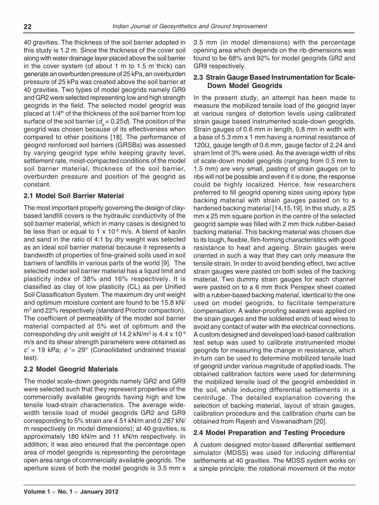
22 Indian Journal of Geosynthetics and Ground Improvement
Volume 1 v No. 1 v January 2012
40 gravities. The thickness of the soil barrier adopted inthis study is 1.2 m. Since the thickness of the cover soilalong with water drainage layer placed above the soil barrierin the cover system (of about 1 m to 1.5 m thick) cangenerate an overburden pressure of 25 kPa, an overburdenpressure of 25 kPa was created above the soil barrier at40 gravities. Two types of model geogrids namely GR9and GR2 were selected representing low and high strengthgeogrids in the field. The selected model geogrid wasplaced at 1/4th of the thickness of the soil barrier from topsurface of the soil barrier (dg = 0.25d). The position of thegeogrid was chosen because of its effectiveness whencompared to other positions [18]. The performance ofgeogrid reinforced soil barriers (GRSBs) was assessedby varying geogrid type while keeping gravity level,settlement rate, moist-compacted conditions of the modelsoil barrier material, thickness of the soil barrier,overburden pressure and position of the geogrid asconstant.
2.1 Model Soil Barrier Material
The most important property governing the design of clay-based landfill covers is the hydraulic conductivity of thesoil barrier material, which in many cases is designed tobe less than or equal to 1 x 10⁻⁹ m/s. A blend of kaolinand sand in the ratio of 4:1 by dry weight was selectedas an ideal soil barrier material because it represents abandwidth of properties of fine-grained soils used in soilbarriers of landfills in various parts of the world [9]. Theselected model soil barrier material has a liquid limit andplasticity index of 38% and 16% respectively. It isclassified as clay of low plasticity (CL) as per UnifiedSoil Classification System. The maximum dry unit weightand optimum moisture content are found to be 15.8 kN/m3 and 22% respectively (standard Proctor compaction).The coefficient of permeability of the model soil barriermaterial compacted at 5% wet of optimum and thecorresponding dry unit weight of 14.2 kN/m3 is 4.4 x 10⁻⁹
m/s and its shear strength parameters were obtained asc’ = 19 kPa; φ ‘= 29° (Consolidated undrained triaxialtest).
2.2 Model Geogrid Materials
The model scale-down geogrids namely GR2 and GR9were selected such that they represent properties of thecommercially available geogrids having high and lowtensile load-strain characteristics. The average wide-width tensile load of model geogrids GR2 and GR9corresponding to 5% strain are 4.51 kN/m and 0.287 kN/m respectively (in model dimensions); at 40 gravities, isapproximately 180 kN/m and 11 kN/m respectively. Inaddition, it was also ensured that the percentage openarea of model geogrids is representing the percentageopen area range of commercially available geogrids. Theaperture sizes of both the model geogrids is 3.5 mm x
3.5 mm (in model dimensions) with the percentageopening area which depends on the rib dimensions wasfound to be 68% and 92% for model geogrids GR2 andGR9 respectively.
2.3 Strain Gauge Based Instrumentation for Scale-Down Model Geogrids
In the present study, an attempt has been made tomeasure the mobilized tensile load of the geogrid layerat various ranges of distortion levels using calibratedstrain gauge based instrumented scale-down geogrids.Strain gauges of 0.6 mm in length, 0.8 mm in width witha base of 5.3 mm x 1 mm having a nominal resistance of120Ω, gauge length of 0.6 mm, gauge factor of 2.24 andstrain limit of 3% were used. As the average width of ribsof scale-down model geogrids (ranging from 0.5 mm to1.5 mm) are very small, pasting of strain gauges on toribs will not be possible and even if it is done, the responsecould be highly localized. Hence, few researcherspreferred to fill geogrid opening sizes using epoxy typebacking material with strain gauges pasted on to ahardened backing material [14,15,19]. In this study, a 25mm x 25 mm square portion in the centre of the selectedgeogrid sample was filled with 2 mm thick rubber-basedbacking material. This backing material was chosen dueto its tough, flexible, film-forming characteristics with goodresistance to heat and ageing. Strain gauges wereoriented in such a way that they can only measure thetensile strain. In order to avoid bending effect, two activestrain gauges were pasted on both sides of the backingmaterial. Two dummy strain gauges for each channelwere pasted on to a 6 mm thick Perspex sheet coatedwith a rubber-based backing material, identical to the oneused on model geogrids, to facilitate temperaturecompensation. A water-proofing sealant was applied onthe strain gauges and the soldered ends of lead wires toavoid any contact of water with the electrical connections.A custom designed and developed load-based calibrationtest setup was used to calibrate instrumented modelgeogrids for measuring the change in resistance, whichin-turn can be used to determine mobilized tensile loadof geogrid under various magnitude of applied loads. Theobtained calibration factors were used for determiningthe mobilized tensile load of the geogrid embedded inthe soil, while inducing differential settlements in acentrifuge. The detailed explanation covering theselection of backing material, layout of strain gauges,calibration procedure and the calibration charts can beobtained from Rajesh and Viswanadham [20].
2.4 Model Preparation and Testing Procedure
A custom designed motor-based differential settlementsimulator (MDSS) was used for inducing differentialsettlements at 40 gravities. The MDSS system works ona simple principle: the rotational movement of the motor

23
Volume 1 v No. 1 v January 2012
shaft is converted to translational movement of the centralplatform through a screw jack and series of gears. Thedescription of MDSS setup, model preparation and testingprocedure has been explained extensively by Rajesh andViswanadham [16]. Figure 1 shows the cross-section ofthe model test package and the configuration of theinstrumentation for inducing differential settlements in aGRSB of landfill covers. By using this arrangement it ispossible to model a landfill cover area as large as 415 m2
in the prototype scale (at 40g). A 30 mm thick model soilbarrier was prepared at its wet side of optimum (OMC+5%)and corresponding unit weight (14.2 kN/m3) above pre-saturated and drained coarse and fine layers of sandhaving 30 mm thickness. The calibrated instrumentedscale-down model geogrid was placed at dg distance andthen the remaining thickness of the soil barrier wasconstructed. Discrete markers are placed on the topsurface of the soil barrier to capture the deformation patternof the soil barrier. In addition to the discrete markers placedon the top surface of the soil barrier, series of discretemarkers were glued on to the instrumented scale-downmodel geogrid in the case of GRSB to measure thedeformation profiles of the geogrid layer. Various sensorslike miniature pore pressure transducers (PPTs), linearlyvariable differential transformers (LVDT) and strain gaugeswere used to measure water breakthrough, displacementprofiles of the soil barrier and mobilized tensile load ofmodel geogrids respectively. Motor of the MDSS systemwas operated at a settlement rate of 1 mm/min usingthyristor controller at 40g with a maximum centralsettlement of 25 mm.
The nature of induced deformation in the soil barrier canbe explained using the parameters like settlement ratioand distortion level. When the horizontal distance fromcentre of the soil barrier x is zero, the value of settlementis termed as a central settlement a (Fig. 1); maximumcentral settlement induced in the present study is 25 mm(1 m at 40g). Settlement ratio, a/amax is defined as the
ratio of central settlement at any stage of deformation ato the maximum central settlement amax. Distortion level,a/l is defined as the ratio of central settlement a to theinfluence length l (which is defined as a distance overwhich induced settlements cease to zero) within whichdifferential settlements are induced (Fig. 1). In the presentstudy, l = 200 mm (in model dimensions) was used. Atvarious stages of central settlements and distortionlevels, photographs were captured using digital photocamera placed on the front side of the model to view righthalf of the front elevation of the soil barrier and were laterused for image analysis to compute displacement profilesand strain distribution along the top surface of the soilbarrier.
3. RESULTS AND DISCUSSION
Table 2 summarizes the results of the centrifuge testscarried out to study the deformation behavior of the soilbarrier with and without the inclusion of geogridreinforcement.
Fig. 1 : Cross-section of model test package (Modified afterRajesh and Viswanadham, 2009)
Table 2 : Summary of centrifuge test results
Parameters URSB GRSB1 GRSB2
Reinforcement type No Low strength geogrid High strength geogrid
d (mm) 1200 (30) 1200 (30) 1200 (30)
σo (kPa) 25 25 25
εmax (%) 3.81 4.01 3.76
dc (mm) 1200 (30) 680 (17) ~ Negligible
(a/l)lim 0.069 0.108 0.125*
Cracking pattern Full depth -narrow crack Fine crack extending to partial depth Tiny surface cracks
d- thickness of the soil barrier; dc – depth of crack measured from the top surface of the soil barrier; σo – overburdenpressure; εmax- maximum tensile strain at the zone of maximum curvature; (a/l)lim- limiting distortion level; *in the presentstudy, soil barrier is subjected to a maximum distortion level of 0.125; Values in model dimensions are given within theparenthesis.
Centrifuge Model Studies on the Performance of Geogrid Reinforced Soil Barriers of Landfill Covers

24 Indian Journal of Geosynthetics and Ground Improvement
Volume 1 v No. 1 v January 2012
3.1 Deformation Pattern
The photographs captured at various stages of centralsettlement through a digital photo camera were used todetermine the displacement of the discrete markers withrespect to a rectangular grid of markers permanently fixedonto the inner side of the Perspex sheet. The coordinatesof each discrete marker at various stages of centralsettlements were determined using digitization of thediscrete markers using GRAM++ [21]. The measuredcoordinates of markers embedded in the soil and geogridare approximated with an exponential equation of thenormal distribution to get the deformation profile of thesoil and geogrid layers at various stages of centralsettlement. Figure 2 shows the displacement profiles ofthe top surface of a 1.2 m thick soil barrier with and withoutgeogrid for various stages of central settlements. It canbe observed that both the un-reinforced soil barrier[Model: URSB] and geogrid reinforced soil barrier [Model:GRSB2] experienced almost identical displacementprofiles at the various stages of central settlements;however, the GRSB was found to deform relatively morewhen compared to the URSB
Soil strain at the geogrid interface εsg can be determinedfrom εs, assuming linear variation of strain across thethickness of the soil barrier:
.. (3)
where, ; =ofR neutral axis factor
(=0.67); =κ curvature at any horizontal distance =w´´(x); w(x) is the equation of the displacement profile,subscript s and g denotes soil and geogrid respectively.
The strain distribution along the top surface of the 1.2 mthick un-reinforced soil barrier (URSB) subjected to anoverburden pressure of 25 kPa at various stages ofcentral settlement is shown in Figure 3a [Model: URSB].It can be observed that as the central settlementincreases, both the tensile and compressive strains alongthe top surface of the soil barrier also increases at thezone of tension and compression zone respectively.Figure 3b shows the variation of strains in geogrid andthe soil along the soil-geogrid interface with the horizontaldistance from the centre of the soil barrier, for the soilbarrier reinforced with an instrumented geogrid GR2[Model: GRSB2]. At lower central settlements, the geogridstrain distribution and the soil strain distribution at thegeogrid interface are almost identical. However, for higher
Fig. 2 : Displacement profiles measured at the top surface ofthe soil barrier with and without geogrid reinforcement forvarious central settlements [Models: URSB and GRSB2]
3.2 Strain Distribution Pattern
Displacement profiles obtained at various stages of centralsettlement were used to determine the strain along thetop surface of the soil barrier. If ws(x) is the function ofdisplacement profile of the top surface of the soil barrierand ws2 (x) and ws2 2 (x) are the first and secondderivatives of ws(x), then the soil strain ås can becomputed using combined bending and elongationmethod [5,22] as follows:
... (1)
Similarly the geogrid strain (åg) can be determined asfollows:
... (2)b) Strains in soil and geogrid along the soil-geogrid interface (εsg, εg)[ Model: GRSB2]
Fig. 3 : Variation of strain distribution along the length of thesoil barrier [Models: URSB and GRSB2]
(a) Soil strain (εs) distribution [Model: URSB]
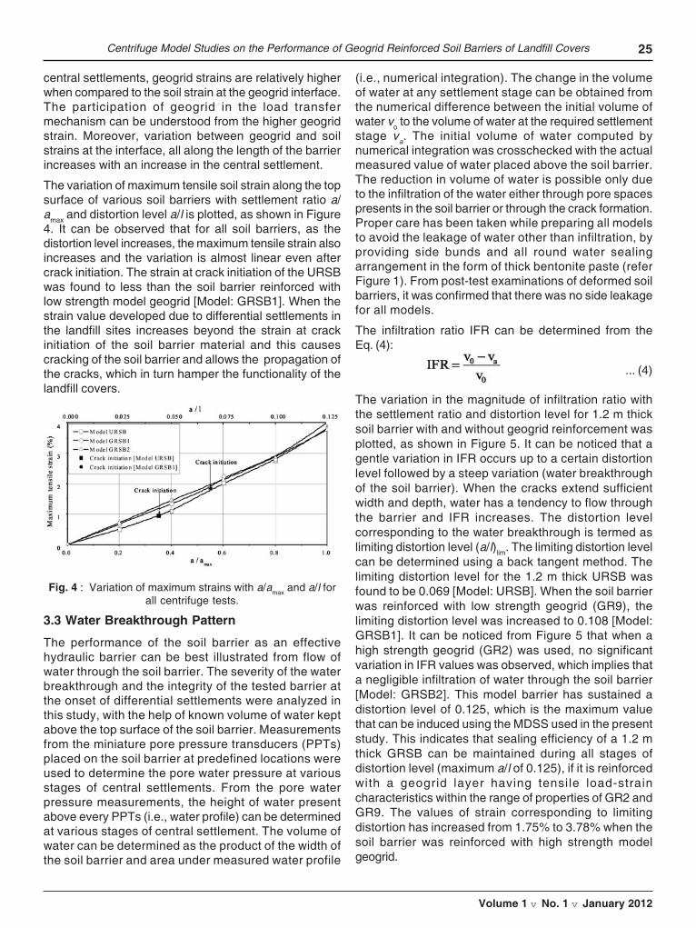
25
Volume 1 v No. 1 v January 2012
central settlements, geogrid strains are relatively higherwhen compared to the soil strain at the geogrid interface.The participation of geogrid in the load transfermechanism can be understood from the higher geogridstrain. Moreover, variation between geogrid and soilstrains at the interface, all along the length of the barrierincreases with an increase in the central settlement.
The variation of maximum tensile soil strain along the topsurface of various soil barriers with settlement ratio a/amax and distortion level a/l is plotted, as shown in Figure4. It can be observed that for all soil barriers, as thedistortion level increases, the maximum tensile strain alsoincreases and the variation is almost linear even aftercrack initiation. The strain at crack initiation of the URSBwas found to less than the soil barrier reinforced withlow strength model geogrid [Model: GRSB1]. When thestrain value developed due to differential settlements inthe landfill sites increases beyond the strain at crackinitiation of the soil barrier material and this causescracking of the soil barrier and allows the propagation ofthe cracks, which in turn hamper the functionality of thelandfill covers.
(i.e., numerical integration). The change in the volumeof water at any settlement stage can be obtained fromthe numerical difference between the initial volume ofwater vo to the volume of water at the required settlementstage va. The initial volume of water computed bynumerical integration was crosschecked with the actualmeasured value of water placed above the soil barrier.The reduction in volume of water is possible only dueto the infiltration of the water either through pore spacespresents in the soil barrier or through the crack formation.Proper care has been taken while preparing all modelsto avoid the leakage of water other than infiltration, byproviding side bunds and all round water sealingarrangement in the form of thick bentonite paste (referFigure 1). From post-test examinations of deformed soilbarriers, it was confirmed that there was no side leakagefor all models.
The infiltration ratio IFR can be determined from theEq. (4):
... (4)
The variation in the magnitude of infiltration ratio withthe settlement ratio and distortion level for 1.2 m thicksoil barrier with and without geogrid reinforcement wasplotted, as shown in Figure 5. It can be noticed that agentle variation in IFR occurs up to a certain distortionlevel followed by a steep variation (water breakthroughof the soil barrier). When the cracks extend sufficientwidth and depth, water has a tendency to flow throughthe barrier and IFR increases. The distortion levelcorresponding to the water breakthrough is termed aslimiting distortion level (a/l)lim. The limiting distortion levelcan be determined using a back tangent method. Thelimiting distortion level for the 1.2 m thick URSB wasfound to be 0.069 [Model: URSB]. When the soil barrierwas reinforced with low strength geogrid (GR9), thelimiting distortion level was increased to 0.108 [Model:GRSB1]. It can be noticed from Figure 5 that when ahigh strength geogrid (GR2) was used, no significantvariation in IFR values was observed, which implies thata negligible infiltration of water through the soil barrier[Model: GRSB2]. This model barrier has sustained adistortion level of 0.125, which is the maximum valuethat can be induced using the MDSS used in the presentstudy. This indicates that sealing efficiency of a 1.2 mthick GRSB can be maintained during all stages ofdistortion level (maximum a/l of 0.125), if it is reinforcedwith a geogrid layer having tensile load-straincharacteristics within the range of properties of GR2 andGR9. The values of strain corresponding to limitingdistortion has increased from 1.75% to 3.78% when thesoil barrier was reinforced with high strength modelgeogrid.
Fig. 4 : Variation of maximum strains with a/amax and a/l forall centrifuge tests.
3.3 Water Breakthrough Pattern
The performance of the soil barrier as an effectivehydraulic barrier can be best illustrated from flow ofwater through the soil barrier. The severity of the waterbreakthrough and the integrity of the tested barrier atthe onset of differential settlements were analyzed inthis study, with the help of known volume of water keptabove the top surface of the soil barrier. Measurementsfrom the miniature pore pressure transducers (PPTs)placed on the soil barrier at predefined locations wereused to determine the pore water pressure at variousstages of central settlements. From the pore waterpressure measurements, the height of water presentabove every PPTs (i.e., water profile) can be determinedat various stages of central settlement. The volume ofwater can be determined as the product of the width ofthe soil barrier and area under measured water profile
Centrifuge Model Studies on the Performance of Geogrid Reinforced Soil Barriers of Landfill Covers

26 Indian Journal of Geosynthetics and Ground Improvement
Volume 1 v No. 1 v January 2012
Fig. 5 : Variation of infiltration ratio with a/amax and a/lfor all centrifuge tests
3.4 Cracking Pattern
The status of 1.2 m thick soil barrier with and withoutgeogrid reinforcement after inducing central settlementof 1 m and distortion level of 0.125 is shown in Figure 6.A clear distinct full-depth crack (i.e., crack depth = 30mm, in model dimensions) can be observed for the URSB.Partial penetration of crack with the average crack depthof 17 mm (in model dimensions) was noticed when thesoil barrier was reinforced with a low strength geogrid[Model: GRSB1]. Interestingly, with the introduction of highstrength geogrid (GR2) within the soil barrier, crack freesoil barrier has been obtained even at a distortion level of
0.125, which clearly demonstrates the effectiveness ofgeogrid reinforcement. The evidence of soil-geogridinteraction can be physically seen from the impression ofgeogrid ribs within the exposed portion of the soil barrierafter completion of centrifuge test (Fib. 6d). The partialpenetration of crack lead to the steep rise in the value ofinfiltration ratio at higher distortion level. In addition, thereason behind the formation of partial penetration of finecracks in GRSB could be due to inadequate mobilizationof the required tensile load along the soil-geogrid interfaceat the onset of differential settlements.
3.5 Mobilized tensile load distribution pattern
The mobilization of the tensile load of the geogrid at variousranges of central settlement and distortion level can beobtained from instrumented geogrids. A distinct increasein the maximum mobilized tensile load at the zone ofmaximum curvature was observed with an increase in thecentral settlement and distortion level. Figure 7 presentsthe variation of maximum mobilized tensile load of thegeogrid against settlement ratio and distortion level forthe soil barrier with low strength geogrid (GR9) and highstrength geogrid (GR2). At every stage of centralsettlement, high strength geogrid could mobilize highertensile load when compared to low strength geogrid. For acentral settlement of 0.4 m, the low strength model geogridcould generate a maximum tensile load of 16 kN/m when
Fig. 6 : Status of soil barriers with and without geogrid reinforcement at the end of centrifuge tests

27
Volume 1 v No. 1 v January 2012
compared to 72 kN/m for a high strength geogrid. Themaximum mobilized tensile load experienced by highstrength geogrid at a central settlement of 1 m (a/l = 0.125)was found to be 120 kN/m [Model: GRSB2], as comparedto 37 kN/m for low strength geogrid [Model: GRSB1]. Inaddition, for central settlements of a = 0.8 m and a = 1 m,the maximum mobilized tensile load of high strengthgeogrid was found to be almost constant, which indicatesthat the geogrid layer has generated the maximum possiblemobilization of the tensile load. This shows the importanceof selection of suitable geogrid type. From the earlierdiscussion, it can be noted that the soil barrier reinforcedwith geogrid GR2 was found to exhibit crack free behaviorwith negligible infiltration even at a central settlement of 1m (a/l = 0.125; a/amax = 1). This study demonstrates thatwhen a 1.2 m thick soil barrier is reinforced with a geogridhaving a tensile load of 120 kN/m (without adopting anysafety factors), a crack free barrier can be ascertainedeven at a distortion level of 0.125.
4. CONCLUSIONS
This paper presents results of centrifuge model testsperformed on 1.2 m thick soil barriers with and withoutthe inclusion of an instrumented geogrid reinforcementlayer to study the sealing efficiency of clay-based landfillcovers and tensile load distribution under various distortionlevels. Based on the analysis and interpretation ofcentrifuge test results, the following conclusions can bedrawn:
• A 1.2 m thick un-reinforced soil barrier subjected toan overburden pressure equivalent to a landfill coversystem was found to experience narrow cracks at thezone of maximum curvature, with the depth of cracksextending up to full-thickness of the soil barrier. Asubstantial reduction in the magnitude of crack widthand depth were noticed when the soil barrier wasreinforced with low strength geogrid. Interestingly withthe inclusion of high strength geogrid within the soilbarrier, crack free soil barrier was noticed even afterinducing distortion level of 0.125.
• The limiting distortion level of URSB was found to be0.069. With the inclusion of low strength geogrid withinthe soil barrier, limiting distortion level was increasedto 0.108. When a high strength geogrid was reinforcedwithin the soil barrier, soil barrier has sustained adistortion level of 0.125 without loss of integrity.
• The maximum mobilized tensile load of low strengthmodel geogrid at a distortion level of 0.125 was foundto be 37 kN/m. However, for identical conditions withhigh strength geogrid, it was observed to increase to120 kN/m.
This study concludes that the performance of a GRSBwas found to be many times superior to the respectiveURSB in terms of both restraining cracks and asubstantial delay in water breakthrough. In addition, it isclearly demonstrated that when a soil barrier is reinforcedwith a suitable geogrid having adequate tensile load- straincharacteristics, it can retain the integrity and maintainthe desired sealing efficiency even at a higher distortionlevel. The developed GRSB can be used as a secondarycontainment in underground storage tanks; lining forcanals; seepage barrier in earthen dams, etc.
Acknowledgments - The authors would like to thank theCentrifuge team at the National Geotechnical CentrifugeFacility of the Indian Institute of Technology Bombay,Powai, Mumbai-400076, India for their untiring supportthroughout the present study.
REFERENCES
1. Heerten G., and Koerner R. 2008. Cover systems forlandfills and brownfields. Land Contamination andReclamation. 16(4): 343-356.
2. Gourc J. P., Camp S., Viswanadham B. V .S., andRajesh S. 2010. Deformation behaviour of clay capbarriers of hazardous waste containment systems:full-scale and centrifuge tests. Geotextiles andGeomembranes. 28(3): 281-291.
3. Keck K. N., and Seitz R. R. 2002. Potential forSubsidence at the Low-Level Radioactive WasteDisposal Area. INEEL/EXT-02-01154, Idaho NationalEngineering and Environmental Laboratory, U.S.Department of Energy, USA.
4. Qian X., Koerner R.M., and Gray D.H. 2002.Geotechnical aspects of landfill design andConstruction. Prentice Hall, New Jersey, USA: 431-436.
5. Lee K.L., and Shen C.K. 1969. Horizontal movementsrelated to subsidence. Journal of Soil Mechanics andFoundation division, ASCE. 94 (6): 139–166.
6. Jessberger H.L., and Stone K.J.L. 1991. Subsidenceeffect on clay barriers. Geotechnique, 41 (2): 185–194.
Fig. 7 : Variation of maximum mobilized tensile load at thezone of maximum curvature with a/amax and a/l
Centrifuge Model Studies on the Performance of Geogrid Reinforced Soil Barriers of Landfill Covers

28 Indian Journal of Geosynthetics and Ground Improvement
Volume 1 v No. 1 v January 2012
7. Liang R. Y., Lommler J. C., Lee S., and Meyers B.1994. Case studies: Clay cover cracking analysisusing FEM techniques. Proc Fracture mechanicsapplied to geotechnical engineering, L.E. Vallejo andR.Y. Liang (Eds.), ASCE Geotechnical SpecialPublication 43: 86-101.
8. Viswanadham B. V. S., and Mahesh K. V. 2002.Modeling deformation behaviour of clay liners in a smallcentrifuge. Canadian Geotechnical Journal. 39(6): 1406-1418.
9. Viswanadham B. V. S., and Rajesh S. 2009. Centrifugemodel test on clay based engineered barriers subjectedto differential settlement. Applied Clay Science. 42(3-4): 460-472.
10. Viswanadham B. V. S., Rajesh S., Divya P. V. and GourcJ. P. 2011. Influence of randomly distributed geofiberson the integrity of clay-based landfill covers: acentrifuge study. Geosynthetics International. 18(5):255–27
11. Viswanadham B. V. S., and Jessberger H. L. 2005.Centrifuge modeling of geosynthetic reinforced clayliner of landfills. Journal of Geotechnical andGeoenvironmental Engineering, ASCE. 131(5): 564-574.
12. Schofield A. N. 1980. Cambridge geotechnicaloperations. Geotechnique. 30(3): 227-268.
13. Taylor R. N. 1995. Centrifuges in modelling: principlesand scale effects. Geotechnical CentrifugeTechnology, R. N. Taylor, ed., Blackie Academic andProfessional, Glasgow, U.K: 19-33.
14. Springman S., Bolton M., Sharma J., andBalachandran S. 1992. Modeling and instrumentationof a geotextile in the geotechnical centrifuge. Proc
International Symposium on Earth ReinforcementPractice, Fukuoka, Japan, Ochiai, H., Hayashi, S.,Otani, J. (Eds.), A.A. Balkema, Rotterdam, 1: 167–172.
15. Viswanadham B. V. S., and König D. 2004. Studieson scaling and instrumentation of a geogrid.Geotextiles and Geomembranes. 22(5): 307-328.
16. Rajesh S., and Viswanadham B.V.S. 2009. Evaluationof geogrid as a reinforcement layer in clay basedengineered barriers. Applied Clay Science, Elsevier.46 (2): 153-165.
17. Chandrasekaran V. S. 2001. Numerical and centrifugemodelling in soil structure interaction. IndianGeotechnical Journal. 31(1): 1-59.
18. Indraratna B., and Lasek G. 1996. Laboratoryevaluation of the load-deflection behaviour of claybeams reinforced with galvanised wire netting.Geotextiles and Geomembranes. 14(10): 555–573.
19. Bolton M. D., and Sharma J. S. 1994. Embankmentswith base reinforcement on soft clay. Proc. Centrifuge‘94, Leung, C.F., Lee, F.H and Tan, T.S., Editors, A.A.Balkema, Rotterdam, 587–592.
20. Rajesh S., and Viswanadham B.V.S. 2011. Modellingand instrumentation of geogrid reinforced soil barriersof landfill covers. Journal of Geotechnical andGeoenvironmental Engineering, ASCE (in press,doi:10.1061/(ASCE)GT:1943-5606.0000559).
21. GRAM ++. 2004. http://www.csre.iitb.ac.in/gram++/
22. Tognon A. R., Rowe R. K., and Moore I. D. 2000.Geomembrane strain observed in large-scale testingof protection layers. Journal of Geotechnical andGeoenvironmental Engineering, ASCE. 126(12):1194-1208.

29
Volume 1 v No. 1 v January 2012
Abstract of Paper shortlisted for IGS Student Paper Award - 2012
EFFECT OF GEOGRID IN SATURATED SAND AGAINSTLIQUEFACTION
Rajiv ChauhanResearch Scholar, Department of Civil Engineering, Indian Institute of Technology, Roorkee
Abstract - Liquefaction is an earthquake associated natural phenomenon, which causes widespread damage to manmade structures. One of major reasons for collapse of structures due to liquefaction is loss of strength due togeneration of excess pore pressure in sandy soils. The pore water pressure response of sandy soils controls theliquefaction behavior. Various kinds of earthquake- resistant methods are available now a days. However, all of thesemethods are expensive and normally require advance construction techniques, which may not be affordable sometimes.The liquefaction studies with geogrid are scanty. The present study addresses the effect on liquefaction behavior ofsand duly reinforced with HDPE geogrid. The uniaxial geogrid made from high strength polyester yarns with blackPVC coating having carbon black as 2% and ultimate tensile strength of 88.7 kN/m was used as reinforcing materialin the study. It was a stiff grid with rectangular openings of size 220 mm × 17 mm and unit weight of 6.5 N/mm2. Testshad been conducted in a rigid steel tank of size 1060 mm length, 600 mm width and 600 mm height mounted on ashake table. The amplitude of motion could be changed through two eccentric shafts. By changing the relativeposition of two shafts, the amplitude could be fixed as desired. The maximum amplitude of horizontal accelerationwhich can be generated in the shake table was up to 0.3g.The hand brake assembly is used for stopping the shaketable instantaneously. The pore pressure measurement was performed with the help of 3 nos. glass tube piezometerseach of 5 mm diameter, attached to the tank through rubber tubes at heights of 80 mm, 180 mm and 260 mm frombottom of tank and were denoted as B, M and T respectively. To check the entry of soil particles into the piezometertubes, porous stones duly wrapped with filter paper were tied at mouth of piezometer tubes. For each acceleration,the relative densities of the sample were also varied from 35% to 50%.The density in the sample was maintained asper guidelines of ASTM D5311-92(reapproved 2004) and Ishihara (1996).The geogrid layers of size 800 mm x 400 mmwere placed in shake table at a vertical spacing of 100 mm c/c in 500 mm depth of sample. This size of geogrid layerwas adopted to eliminate the boundary effects on it. When soil was reinforced with 4 nos. geogrid layers placedequidistant vertically and shaking was imparted, the average excess pore pressure decreases from 3.31 kN/m2 (forvirgin soil) to 2.41 kN/m2( for reinforced soil) respectively for 35% relative density at 0.1g. This trend was furtherobserved at higher acceleration values i.e. 3.64 kN/m2 (for virgin soil) to 2.87 kN/m2 (for reinforced soil) at 0.3g forsame density. Thus average decrease in excess pore pressure was 27% at 0.1g and 21% at 0.3g at 35% relativedensity. A new parameter i.e. Liquefaction Resistance Factor (LRF) has been introduced which is ratio of excess porepressure to effective overburden pressure. If this value is equal to or greater than 1.0, liquefaction is likely to occur,and if it is below 1.0 then there will not be any liquefaction. The liquefaction resistance of sand increases due toaddition of geogrid layers. For 35% relative density, the average increase in liquefaction resistance was about 23 %with 4 nos. geogrid layers at 0.1g.Further by increasing acceleration to 0.3g, the liquefaction resistance was 20% forsame density. For 50% relative density, the average liquefaction resistance factor comes down from 1.18 (for virginsoil) to 0.893 (for reinforced sand) at 0.3g. Effect of surcharge was also studied on reinforced sand to simulate fieldconditions. The surcharge applied was through precast concrete blocks. Each concrete block was weighing approximately1800 N. These were placed on a 10 mm thick steel plate placed on the soil sample for applying the load on to the soilsample uniformly. These concrete blocks were loaded and removed after test with the help of a chain pulley block(Mittal, 1988). The blocks were rigidly connected to each other through 4 Nos. steel anchor bolts and two steelchannels; so that their position was not disturbed under the action of dynamic loads. Different surcharges wereapplied on sand sample. With the application of 5.94 kN/m2 surcharge, the average liquefaction resistance factorincreased to 28 % at 0.3g at 50% relative density. This shows that it works in good arrangement under overburdenconditions also. Settlement behavior of sand with and without reinforcement was also studied. In case of virgin soil,18.8 mm of settlement reduces to 15.2 mm with inclusion of 4 nos. geogrid layers at 35% relative density for 0.1
30 Indian Journal of Geosynthetics and Ground Improvement
Volume 1 v No. 1 v January 2012
g.This trend was further observed at higher acceleration values also. Excess pore pressure build up time i.e. time toreach maximum pore pressure was also studied. For reinforced sand, the pore pressure build up time increased from17.6 seconds to 48.3 seconds for 35% relative density at 0.3g. Similarly excess pore pressure dissipation time alsoincreased from 80 seconds (for virgin soil) to 119 seconds (for reinforced sand) at 35% relative density for 0.1g.
From this study, it is concluded that liquefaction potential of fine sand can be significantly reduced by use of geogridreinforcements. Therefore, such study suggests that prior to construction of new embankments (railways or highways)and underground structures e.g., reservoir etc., if ground is reinforced with geogrids, the severity of damages couldbe minimized to a great extent.
Acknowledgement - The present paper is outcome of research work in progress at IIT; Roorkee under the guidanceof Dr. Satyendra Mittal .The research is supported by a fellowship to author from, Govt. of India through MHRDscheme.
REFERENCES
ASTM D5311-92 (2004), Standard Test Method for Load Controlled Cyclic Triaxial Strength of Soil, pp 1-10.
Ishihara, K. (1996). Soil Behavior in Earthquake Geotechnics, 1stEd. Oxford, Clarendon Press, pp 350.
Mittal, S. (1988). Vibration table studies for prediction of Liquefaction - a critical study, M.Tech Thesis, University ofRoorkee, Roorkee, India
BEHAVIOUR OF GEOCELL IN COHESIONLESS SOIL –AN EXPERIMENTAL STUDY
Sefali BiswasAssistant Engineer, PWD, Government of West Bengal, Kolkata
Abstract – A numbers of ground improvement techniques are available for improving the load carrying capacity andengineering properties of those soils which otherwise are not suitable for normal construction. An examination of theexisting literature indicates that the bearing capacity is considerable improved with planar geogrid. Present work isfocused on 3D reinforcement i.e. geocell. However, a comparative study has also been done on the performances ofgeocells and planar geogrids. The soil used in the model tests was locally collected Solani river sand with relativedensity as 60% and shear parameters c=0 & Ø=320. The soil classification was SP. A rigid square steel tank of size1130 mm x 1130mm x 800 mm was used in the laboratory model test. The footing was 200 mm x 200 mm x 10 mmsteel rigid M S plate. Two types of reinforcements e.g. planar geogrid and 3D geocell were used. The geocell weremade by using RE 80 Tensar uniaxial geogrid with tensile strength 88.7 kN/m. The geocell had aperture size of 200mm x 200 mm with diamond pattern and cell height of 200 mm.
Numerical analysis results obtained by PLAXIS software had been compared with those obtained from experimentsand were found to be in good agreement. A parametric study revealed the role of reinforcement on bearing capacity interms of its length, spacing between layers etc. The study shows that the improvement in bearing capacity withrespect to unreinforced soil was of the order of 93.75% and settlement reduction was 13.07% for single layer ofgeocell which for double layers of geocell is 298% and 86.48% respectively. Study shows that the savings in cost is21.6% for single of layer of geocell and 91.5% for double layers of geocell with respect to unreinforced soil.The totallength of reinforcement used in model test was 700 mm. Location of reinforcement from top for single layer of geogridwas kept as 0.5 times the width (B) of footing. In case of double layers of geogrid, first layer was placed at 0.5 B andsecond layer was placed at 1B from top surface of soil. In the case of geocell tests, the single layer was placed at0.5B depth and for double layers tests, the geocell were placed at 0.5 B depth and 1.75B from top.
For verification of the the results obtained by model test with Plaxis Software, the value of was obtained byconducting large size direct shear tests, conducted on soil sample of 300 mm x 300 mm x 200 mm size. The resultsobtained by experimental work and by Plaxis analysis were within ± 12%. The cost comparison was done for a virtualproblem of a RCC column of size 400 mm x 400 mm, proposed to cater a load of 1500 kN, the foundation of which wasproposed either on unreinforced soil or soil reinforced with geocell. The design was done for 25mm permissible

31
Volume 1 v No. 1 v January 2012
settlement, (Structural design done as per IS 456:2000). The same is explained in following table (rates as per currentprevailing rates in West Bengal PWD)
Items Virgin Soil Soil reinforced with single layer Soil reinforced with doubleof geocell layers of geocell
Bearing capacity 104 kN/m2 193.75 kN/m2 759 kN/m2
Foundation size 4200 mm x 4200 mm 3000 mm x 3000 mm 1500 mm x 1500 mm(RCC isolated footing) (RCC isolated footing) (RCC isolated footing)
Concrete volume 5.36 m3 2.99 m3 1.04 m3
Steel 542 kg 304 Kg 66 Kg
Geocell Cost - Rs 17,820/-. Rs. 9,460/-.
Total Cost Rs. 55,616/- Rs. 48,916/- Rs. 18,568/-
From this study, it is concluded that foundations supported on geocell reinforced soil are very economical and smallerin size as compared to those supported on soil without reinforcement.
Acknowledgement – The present research work has been done under the guidance of Dr. Satyendra Mittal at IITRoorkee, as part of M. Tech. dissertation work.
CALENDAR OF EVENTS
1. GeoAmericas 2012, II Pan-American Congress on Geosynthetics, Lima, Peru, May 2012 (www.igsperu.org)
2. 12th Baltic Sea Geotechnical Conference, Rostock, Germany, 31 May – 02 June 2012 (E-mail:[email protected]; [email protected] / www.12bsgc.de)
3. 11th Australia – New Zealand Conference on Geomechanics, Melbourne, Australia, 15-18 July 2012 (E-mail: [email protected] www.anz2012.com.au)
4. EUROGEO5 – 5th European Geosynthetics Conference Valencia, Spain, 16-19 September 2012 (E-mail:[email protected] / www.eurogeo5.org)
5. International Conference on Ground Improvement and Ground Control: Transport Infrastructure Developmentand Natural Hazards Mitigation, Wollongong, New South Wales, Australia, 30 October – 02 November2012 (E-mail: [email protected])
6. 32 Baugrundtagung with Exhibition “Geotechnik”, Mainz, Germany, 26-29 November 2012
7. GEOSYNTHETICS ASIA 2012 (GA2012) – 5th Asian Regional Conference on Geosynthetics, Bangkok,Thailand, 10-14 December 2012 (www.set.ait.ac.th/acsig/igs-thailand)
8. 10th International Conference on Geosynthetics, Berlin, Germany, 21-25 September 2014 ([email protected] / www.10icg-berlin.com)
Behaviour of Geocell in Cohesionless Soil – An Experimental Study

32 Indian Journal of Geosynthetics and Ground Improvement
Volume 1 v No. 1 v January 2012
Jute Technology Mission was commissioned by theMinistry of Textiles, Govt of India in 2008 for overallimprovement of jute-production, total qualitymanagement, innovation in design, re-orientation ofmarketing approach etc. The Mission includes an R & Dcomponent to ensure greater acceptability of jute-basedproducts. Jute Geotextiles (JGT) being one of the majorthrust areas, the following R & D projects were includedunder the Mission. National Jute Board (NJB) isresponsible for execution of the schemes. The R&Dprojects are :
1. Development of water-repellent and durable JuteGeotextiles with natural eco-friendly additive forerosion control applications
2. Development of a suitable overlay fabric to serveas a cheaper substitute of bitumen mastic
The project in Sl 1 was entrusted to IIT, Khragpur andthe second project to the Institute of Jute Technology(IJT), Kolkata in collaboration with Central RoadResearch Institute (CRRI), Delhi.
Need for Project in Sl 1
The prevalent practice in river-related applications forJGT is to treat the fabric with industrial bitumen usuallyof Viscosity Grade 30.Bitumen-smeared JGT is supposedto protect the fabric from direct water-contact. As a result,however, completely bitumen-coated JGT does not allowcharacteristics of jute to manifest. The newly developedwater-repellent and durable JGT should thereforeconcurrently address eco-compatibility requirements.This could be done if a benign natural additive can befound to treat JGT for the purpose.
Interim Results
It has been reported that half-life (in months) i.e. estimatedservice life expectancy of the JGT treated at the fabric-level compared to JGT made of untreated fibres standas under. Half life is the time taken by JGT to reach halfof the initial strength. The rate of loss in strength getsslower once the half life is reached.
Technical Report
REPORT ON R & D ACTIVITIES RELATED TO JUTEGEOTEXTILES (JGT)
Tapobrata SanyalChief Consultant, National Jute Board
Treatment Half Service Life (in months)UV soil saline normal
water waterTreatment of JGT at 37 44 51 54fabric level
Untreated JGT 12 14 18 20
The project is in the final stages of completion.
Need for Project in Sl 2
In view of the rising cost of bitumen, the cost of bitumenmastic used as overlay/wearing course on roads ismounting. Considering the fact that jute and bitumen haveexcellent thermal compatibility, jute-based overlay couldbe a viable and cheaper substitute of the conventionalbitumen mastic. The core of the overlay will be made upof a combination of woven and non-woven fabric. Thenon-woven jute fabric is a good receptor of bitumen andwill thus help integrate the jute-bitumen combination.
The project needs to decide on the appropriate jute fabriccore (combination of woven and non-woven fabric) andthe right type of bitumen for the jute combination. Both theactivities necessitate elaborate trials in the laboratory. Thejute-related part is being looked after by IJT while thesuitability of the bitumen type is being examined by CRRI.
Interim Results
IJT has finalized the jute combination (non-woven fabricsandwiched between two layers of woven fabric) and CRRIthe bitumen-type (polymer-modified). Presently laboratorytrials are on at CRRI to check the technical effectivenessof the developed jute-bitumen mastic through lab- scaletrials. The interim results are encouraging.
The project is in the final stages of completion.
The developed products will be subjected to mill-scaletrials for commercial production followed by field trials.IIT, Kharagpur is also working on development of JGTcoated with natural rubber additionally, as a part ofanother project, for application in river bank erosioncontrol. The results appear to be encouraging.

33
Volume 1 v No. 1 v January 2012
INTERNATIONAL GEOSYNTHETICS SOCIETY
The International Geosynthetics Society (IGS) was founded in Paris, on 10 November 1983, by a group of geotechnicalengineers and textile specialists. The Society brings together individual and corporate members from all parts of theworld, who are involved in the design, manufacture, sale, use or testing of geotextiles, geomembranes, relatedproducts and associated technologies, or who teach or conduct research about such products.
The IGS is dedicated to the scientific and engineering development of geotextiles, geomembranes, relatedproducts and associated technologies. IGS has 34 chapters, over 2,800 individual members and 143 corporatemembers.
The aims of the IGS are:
• to collect and disseminate knowledge on all matters relevant to geotextiles, geomembranes and relatedproducts, e.g. by promoting seminars, conferences, etc.
• to promote advancement of the state of the art of geotextiles, geomembranes and related products and oftheir applications, e.g. by encouraging, through its members, the harmonization of test methods, equipmentand criteria.
• to improve communication and understanding regarding such products, e.g. between designers, manufacturersand users and especially between the textile and civil engineering communities
The IGS is registered in the USA as a non-profit organization. It is managed by five Officers and a Council made upof 10 to 16 elected members and a maximum of 5 additional co-opted members. These Officers and Councilmembers are responsible to the General Assembly of members which elects them and decides on the mainorientations of the Society.
IGS Chapters
The IGS Chapters are the premier vehicle through which the IGS reaches out to and influences the marketplace andthe industry. Chapter activities range from the organization of major conferences and exhibits such as the 9thInternational Conference on Geosynthetics in May 2010 in Brazil and its predecessors in Yokohama, Nice andAtlanta to the presentation of focused seminars at universities, government offices and companies. Chapters createthe opportunity for the chapter (and IGS) membership to reach out, to teach and to communicate and they are thecatalyst for many advances in geosynthetics. Participation in an IGS chapter brings researchers, contractors,engineers and designers together in an environment which directly grows the practice by informing and influencingthose who are not familiar with our discipline.
Membership
Membership of IGS is primarily organised through national Chapters. Most individual members (94%) belong to theIGS through Chapters. Chapter participation allows members to be informed about, and participate in, local andregional activities in addition to providing access to the resources of the IGS.
IGS Offers the following categories of membership:
Individual
Individual member benefits are extended to each and every individual member of the IGS including Chapter Members. Additional chapter benefits are provided to Individual Members who join the IGS through a chapter.
Individual Member Benefits include:
• a membership card
• an IGS lapel pin
• on-line access to the IGS Membership Directory, published yearly, with full addresses, telephone, email andfax numbers of members
• the IGS News newsletter, published three times a year
• on-line access to the 19 IGS Mini Lecture Series for the use of the membership

34 Indian Journal of Geosynthetics and Ground Improvement
Volume 1 v No. 1 v January 2012
• on-line access to the 3 IGS Videos for the use of the membership
• information on test methods and standards
• discount rates:
o for any document published in the future by IGS
o at all international, regional or national conferences organized by the IGS or under its auspices
• preferential treatment at conferences organized by the IGS or under its auspices
• possibility of being granted an IGS award
• Free access to the Geosynthetics International journal, now published electronically.
• Free access to the Geotextiles and Geomembranes journal, now published electronically.
Corporate
Corporate Membership Benefits include:
• a membership card
• an IGS lapel pin
• on-line access to the IGS Membership Directory, published yearly, with full addresses, telephone, email andfax numbers of members
• the IGS News newsletter, published three times a year
• on-line access to the 19 IGS Mini Lecture Series for the use of the membership
• on-line access to the 3 IGS Videos for the use of the membership
• information on test methods and standards
• discount rates:
o for any document published in the future by IGS
o at all international, regional or national conferences organized by the IGS or under its auspices
• preferential treatment at conferences organized by the IGS or under its auspices
• possibility of being granted an IGS award
• Free access to the Geosynthetics International journal, now published electronically.
• Free access to the Geotextiles and Geomembranes journal, now published electronically.• advertisement in the IGS Member Directory and on the IGS Website• IGS Corporate Membership Plaque• your Company Profile in the IGS News• right of using the IGS logo at exhibitions and in promotional literature• priority (by seniority of membership within the IGS) at all exhibits organized by the IGS or under its
“auspices”• opportunity to join IGS committees in order to discuss topics of common interest.
Student
Student Membership Benefits include:
• Electronic access to the IGS News, published 3 times a year
• Special Student discounts at all IGS sponsored/supported conferences, seminars etc.
• Listing in a special student members category in the IGS Directory (this may help both the student and futureemployers in making contact).
• Eligibility for awards (and in particular the IGS Young Member Award).
35
Volume 1 v No. 1 v January 2012
Benefactor
Individuals or organizations who voluntarily contribute a minimum of US $ 200 annually to the society, receive aspecial mention and are being listed separately as “benefactors” in the IGS directory of members.
Benefactors & Honorary Members
Honorary Members
Prof. Masami Fukuoka, Japan - Since 1989
Mr. Gert den Hoedt, The Netherlands - Since 1994
Dr. J.P. Giroud, USA - Since 2002
Dr. R. K. Rowe, Canada - Since 2006
Dr. Robert Koerner, USA - Since 2008
Mr. Peter E. Stevenson, USA - Since 2010
LIST OF BENEFACTORS
Individuals or organizations who voluntarily contribute a minimum of US $ 200 annually to the society receive aspecial mention and are being listed separately as “Benefactors” in the IGS Membership Directory.
Mr. Carroll B. Hart, Belton Industries, USA - Since 1990
Mr. Vadim Boubnovsky, OJSC “494 UNR,” Russia - Since 2003
Mr. Massimo Ciarla, Maccaferri Inc., USA - Since 2009
Mr. Xuewen Wang, Taian Modern Plastic Co. Ltd., China (Peoples Republic) - Since 2009
Ing. Ignacio Perez Cuevas, Amanco Mexico S.A. de C.V., Mexico - Since 2010
Mr. Zhanyuan Zhang, Yixing Shenzhou Earth Working Material Co., Ltd., China (Peoples Republic) - Since2010
Imgeocosta Sas, Lilia Cera-Villegas, Colombia - Since 2011
Qingzhong Liao, Beijing Sinoma Bauchem Technology Co., Ltd. - Since 2011
International Geosynthetics Society

36 Indian Journal of Geosynthetics and Ground Improvement
Volume 1 v No. 1 v January 2012
INTERNATIONAL GEOSYNTHETICS SOCIETY (INDIA)
INTRODUCTION
In the year 1985, Central Board of Irrigation and Power, (CBIP) as part of its technology forecasting activities identifiedgeosynthetics as an important area relevant to India’s need for infrastructure development, including roads.
CBIP, since its inception in 1927, is engaged in the dissemination of information regarding recent technologicaladvancements in the disciplines of water resources, power and renewable energy. Besides, it provides a forum forexchange of experiences, facilitating flow of technology through the organisation of symposia, seminars, workshops,training courses, both at national as well international levels, in liaison with international organisations. A briefprofile of CBIP is enclosed.
The CBIP acts as Secretariat of the Indian Chapter as well as Indian National Group of many internationalorganisations like International Water Resources Association (IWRA), World Water Council (WWC), InternationalCommission on Large Dams (ICOLD), International Society for Rock Mechanics (ISRM), International Tunnellingand Underground Space Association (ITA), in addition to International Geosynthetics Society (IGS).
After approval of IGS Council for the formation of Indian Chapter in October 1988, the Indian Chapter of IGS was gotregistered under Societies Registration Act XXI of 1860 of India in June 1992 as the Committee for International GeotextileSociety (India). The Chapter has since been renamed as International Geosynthetics Society (India), in view of theparent body having changed its name from International Geotextiles Society to International Geosynthetics Society.
OBJECTIVES
- to collect and disseminate knowledge on all matters relevant to geotextiles, geomembranes and relatedproducts, e.g. by promoting seminars, conferences etc.;
- to promote advancement of the state-of-the-art of geotextiles, geomembranes and related products and oftheir applications, e.g. by encouraging, through its members, the harmonization of test methods, equipmentand criteria; and
- to improve communication and understanding regarding such products, e.g. between designers, manufacturersand users and especially between the textile and civil engineering communities.
EXECUTIVE BOARD
The Executive Board of the Indian Chapter consists of President, elected by the General Body, two Vice-Presidents,with one elected by the General Body, and second Vice President being Vice President (Civil) of the CBIP as Ex-Officio Vice President and 16 members. The minimum strength of the Executive Board is 07 and maximum 19,including office bearers.The term of the Executive Board is two years and elected members are not eligible for more than two consecutive terms.The Secretary of the CBIP acts as Member Secretary, and is the Chief Executive of the Chapter. Director (WR),CBIP is Ex-Officio Treasurer of the Chapter.
MEMBERSHIP ELIGIBILITY
Membership is open to individuals/institutions, whose activities or interests are clearly related to the scientific,technological or practical development or use of geotextiles, geomembranes, related products and associatedtechnologies.
Membership FeeThe Membership fee payable on calendar year basis is:
• Individual Member Indian Rs. 2,000/-
• Institutional Member (for one calendar year) Indian Rs. 20,000/-
• Institutional Member (for two calendar years) Indian Rs. 35,000/-
• Institutional Member (for three calendar years) Indian Rs. 50,000/-
• Student NIL

37
Volume 1 v No. 1 v January 2012
BENEFITS
Institutional Member
• 4 representatives to be made individual members of IGS (India) and IGS, free from payment of individualmembership fee of Rs. 2,000/- per member.
• One copy each of the publications brought by the IGS (India) in future
• Discount of Rs. 500/- in the registration fee to each of the representatives in each event to be organised bythe IGS (India) during the period of membership.
• Right of using the IGS (India) logo at exhibitions and in promotional literature;
• Priority (by seniority) at all exhibits organised by IGS (India);
• Possibility of joining a specific international committee in order to discus topics of common interest
• Promotion of activities through Indian Chapter News Bulletin
Individual Member
• a membership card from IGS Secretariat;
• an IGS lapel pin;
• IGS NEWS, published three times a year, and IGS (India) News Bulletin, published two times a year;
• information on current test methods and standards
• preferential treatment at conferences organised by IGS (India) and IGS or under its auspices;
• possibility of being granted an IGS award.
• discount rates:
- for any document published in the future by IGS and IGS (India);
- at all international, regional or national conferences organised by IGS (India) and IGS or under itsauspices;
- for the subscription of the journal “Geotextiles and Geomembranes”;
- for the subscription of the journal “Geosynthetics International”.
Student Member
• information on current test methods and standards;
• preferential treatment at conferences organised by IGS (India);
• IGS NEWS, published three times a year, and IGS (India) News Bulletin, published two times a year;
• listing of theses relating to geosynthetics in the IGS News and IGS (India) News Bulletin.
• Special Student discounts:
- at all international, regional or national conferences organised by IGS (India) and IGS or under itsauspices;
- eligibility for awards (and in particular the IGS Young Member Award)
EXECUTIVE BOARD 2010-2012
President:
• Dr. K. Rajagopal, Professor, Department of Civil Engineering, IIT Madras
Vice-President:
• Dr. G.V.S. Raju, Chief Engineer (R&B), Govt. of Andhra Pradesh
Immediate Past President:
• Dr. G.V. Rao, Chairman, SAGES
International Geosynthetics Society (India)

38 Indian Journal of Geosynthetics and Ground Improvement
Volume 1 v No. 1 v January 2012
Members:
• Mr. Arvind Kumar, CEO, Aravali Power Company Pvt. Ltd.
• Mr. P.K. Choudhury, Incharge, Geotech Cell, Indian Jute Industries’ Research Association
• Mr. Narendra Dalmia, Director, Strata Geosystems (India) Pvt. Ltd.
• Mr. C.R. Devaraj, Managing Director, Charankattu Coir Mfg. Co. (P) Ltd.
• Mr. Ashish D. Gharpure, COO and Director, Maccaferri Environmental Solutions Pvt. Ltd.
• Mr. S. Jaswant Kumar, Chief General Manager, National Highways Authority of India
• Mr. M. Kumaraswamy Pillai, Director, Coir Board
• Mr. Satish Naik, CEO, Best Geotechnics Pvt. Ltd.
• Mr. Murari Ratnam, Director, Central Soil and Materials Research Station
Member Secretary:
• Mr. V.K. Kanjlia, Secretary, Central Board of Irrigation and Power
Treasurer:
• Mr. A.C. Gupta, Director (WR), Central Board of Irrigation & Power
EVENTS ORGANISED/SUPPORTED SINCE 2000
1. Seminar on “Coir Geotextiles-Environmental Perspectives”, November 2000, New Delhi
2. Second National Seminar on “Coir Geotextiles – Environmental Perspectives”, April 2001, Guwahati, Assam
3. National Seminar on “Application Of Jute Geotextiles in Civil Engineering”, May 2001, New Delhi
4. International Course on “Geosynthetics in Civil Engineering”, September 2001, Kathmandu, Nepal
5. Second International Conference on “Water Quality Management”, February 2003, New Delhi
6. Workshop on “Applications of Geosynthetics in Infrastructure Projects”, November 2003, New Delhi
7. Geosynthetics India 2004 – A Seminar Workshop on “Geotechnical Engineering Practice with Geosynthetics”,October 2004, New Delhi
8. Introductory Course on Geosynthetics, November 2006, New Delhi
9. International Seminar on “Geosynthetics in India – Present and Future” (in Commemoration of Two Decades ofGeosynthetics in India), November 2006, New Delhi
10. Workshop on “Retaining Structures with Geosynthetics”, December 2006, Chennai (Tamil Nadu)
11. Workshop on “Applications of Geosynthetics – Present and Future”, 20-21 September 2007, Ahmedabad(Gujarat)
12. International Seminar “Geosynthetics India’08" and “Introductory Course on Geosynthetics”, 19-21 November2008, Hyderabad
13. Seminar on “Application of Geosynthetics”, 22 July 2010, New Delhi
14. International Seminar on “Applications of Geosynthetics”, 12 November 2010, New Delhi
15. Seminar “Geosynthetics India’11", including An Introductory Course on Geosynthetics, 22-24 September2011, IIT Madras
LIST OF PUBLICATIONS
1. Use of Geosynthetics – Indian Experiences and Potential – A State of Art Report
2. National Workshop on Role of Geosynthetics in Water Resources Projects
3. Monograph on Particulate Approach to Analysis of Stone Columns with and without Geosynthetics Encasing
4. Recent Developments in the Design of Embankments on Soft Soils

39
Volume 1 v No. 1 v January 2012
5. Proceedings of 2nd International Workshop on Geotextiles
6. Directory of Geotextiles in India – Vol. I
7. An Introduction to Geotextiles and Related Products in Civil Engineering Applications
8. Engineering with Geosynthetics
9. Ground Improvement with Geosynthetics
10. Geosynthetics in Dam Engineering
11. Erosion Control with Geosynthetics
12. Directory of Geosynthetics in India. Vol. II
13. Bibliography – The Indian Contribution to Geosynthetics
14. Waste Containment with Geosynthetics
15. Geosynthetic Applications in Civil Engineering- A Short Course
16. Case Histories of Geosynthetics in Infrastructure Projects
17. Geosynthetics – Recent Developments (Commemorative Volume)
18. Proceedings of International Seminar on “Geosynthetics in India – Present and Future”
19. Proceedings of the Workshop on “Applications of Geosynthetics – Present and Future”, 20-21 September2007, Ahmedabad
20. Directory of Geosynthetics in India – 2008
21 Proceedings of “Geosynthetics India’11"
SECRETARIAT
All correspondences relating to the Society should be addressed to:
Mr. V.K. KanjliaSecretaryCentral Board of Irrigation & PowerMalcha Marg, ChanakyapuriNew Delhi 110 021, India
Contact Person : Mr. Uday Chander, Senior ManagerPhone : +91-11- 2611 5984, Extn. 114Fax : +91-11-2611 6347E-Mail : [email protected]; [email protected]
International Geosynthetics Society (India)
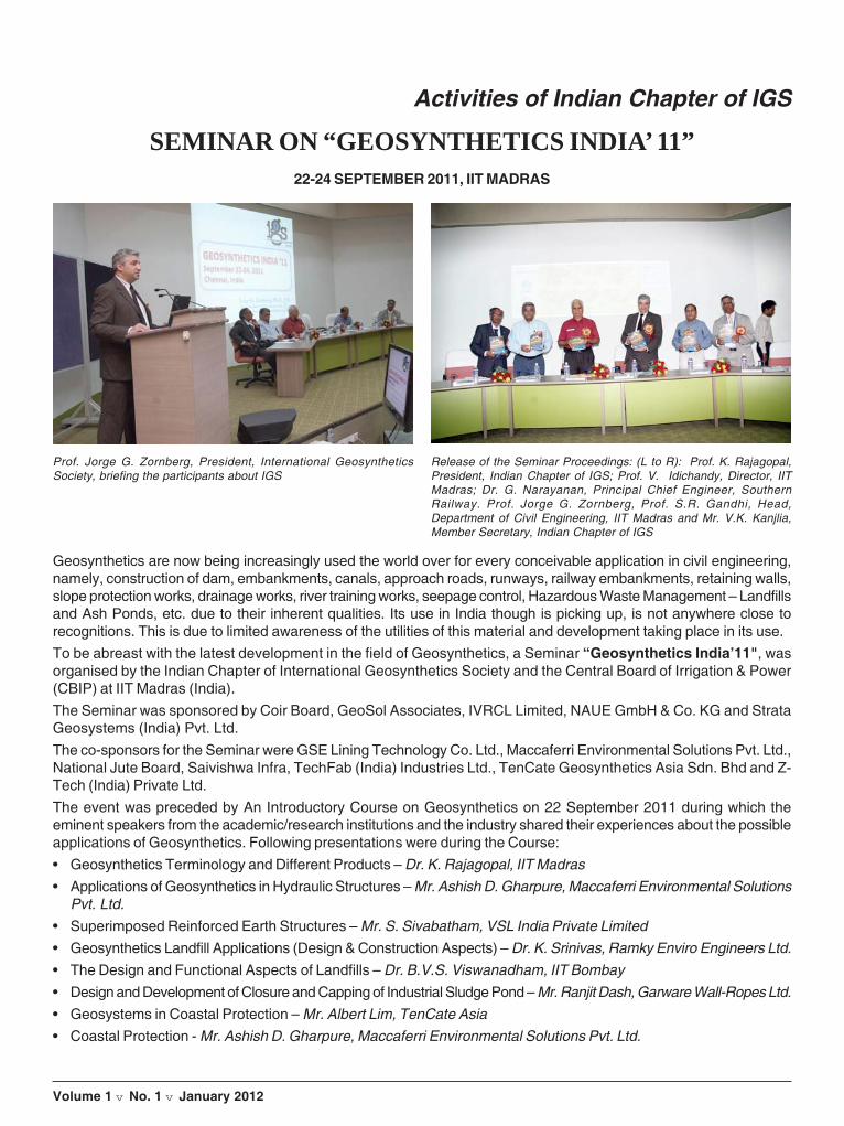
40 Indian Journal of Geosynthetics and Ground Improvement
Volume 1 v No. 1 v January 2012
Activities of Indian Chapter of IGS
SEMINAR ON “GEOSYNTHETICS INDIA’ 11”22-24 SEPTEMBER 2011, IIT MADRAS
Geosynthetics are now being increasingly used the world over for every conceivable application in civil engineering,namely, construction of dam, embankments, canals, approach roads, runways, railway embankments, retaining walls,slope protection works, drainage works, river training works, seepage control, Hazardous Waste Management – Landfillsand Ash Ponds, etc. due to their inherent qualities. Its use in India though is picking up, is not anywhere close torecognitions. This is due to limited awareness of the utilities of this material and development taking place in its use.To be abreast with the latest development in the field of Geosynthetics, a Seminar “Geosynthetics India’11", wasorganised by the Indian Chapter of International Geosynthetics Society and the Central Board of Irrigation & Power(CBIP) at IIT Madras (India).The Seminar was sponsored by Coir Board, GeoSol Associates, IVRCL Limited, NAUE GmbH & Co. KG and StrataGeosystems (India) Pvt. Ltd.The co-sponsors for the Seminar were GSE Lining Technology Co. Ltd., Maccaferri Environmental Solutions Pvt. Ltd.,National Jute Board, Saivishwa Infra, TechFab (India) Industries Ltd., TenCate Geosynthetics Asia Sdn. Bhd and Z-Tech (India) Private Ltd.The event was preceded by An Introductory Course on Geosynthetics on 22 September 2011 during which theeminent speakers from the academic/research institutions and the industry shared their experiences about the possibleapplications of Geosynthetics. Following presentations were during the Course:• Geosynthetics Terminology and Different Products – Dr. K. Rajagopal, IIT Madras• Applications of Geosynthetics in Hydraulic Structures – Mr. Ashish D. Gharpure, Maccaferri Environmental Solutions
Pvt. Ltd.• Superimposed Reinforced Earth Structures – Mr. S. Sivabatham, VSL India Private Limited• Geosynthetics Landfill Applications (Design & Construction Aspects) – Dr. K. Srinivas, Ramky Enviro Engineers Ltd.• The Design and Functional Aspects of Landfills – Dr. B.V.S. Viswanadham, IIT Bombay• Design and Development of Closure and Capping of Industrial Sludge Pond – Mr. Ranjit Dash, Garware Wall-Ropes Ltd.• Geosystems in Coastal Protection – Mr. Albert Lim, TenCate Asia• Coastal Protection - Mr. Ashish D. Gharpure, Maccaferri Environmental Solutions Pvt. Ltd.
Prof. Jorge G. Zornberg, President, International GeosyntheticsSociety, briefing the participants about IGS
Release of the Seminar Proceedings: (L to R): Prof. K. Rajagopal,President, Indian Chapter of IGS; Prof. V. Idichandy, Director, IITMadras; Dr. G. Narayanan, Principal Chief Engineer, SouthernRailway. Prof. Jorge G. Zornberg, Prof. S.R. Gandhi, Head,Department of Civil Engineering, IIT Madras and Mr. V.K. Kanjlia,Member Secretary, Indian Chapter of IGS

41
Volume 1 v No. 1 v January 2012
• Geosystems for Erosion Management in Rivers and Coastal Areas – Mr. Rohit Chaturvedi, Techfab (India) Industries Ltd.• Applications of Waterproofing Geomembrane Systems in India – Mr. V. Subramanian, Carpi India Waterproofing
Specialists Private Limited• Construction Aspects of Segmental Retaining Walls – Mr. Satish Naik, Best Geotechnics Pvt. Ltd.• Geosynthetic Reinforced Embankments and Slopes – Dr. Gali Madhavi Latha, Indian Institute of Science, Bangalore• Testing - Dr. K. Rajagopal, IIT MadrasIn total 90 participants took active participation in the Introductory Course.The Seminar was inaugurated on 23 September 2011 by Dr. G. Narayanan, Principal Chief Engineer, SouthernRailway. Prof. V. Idichandy, Director, IIT Madras presided over the Inaugural Session. Prof. Jorge G. Zornberg,President, International Geosynthetics Society and Fluor Centennial Associate Professor, The University of Texas atAustin, USA also addressed the participants during the Inaugural Session.In total 125 participants from India, besides from Germany, Israel, Japan, Thailand and USA participated in theSeminar.12 organisations from India, besides Germany, Israel and Malaysia displayed their products/services in the Exhibitionorganized during the event.Following keynote lectures and papers were presented and discussed during the Seminar:• Advances in the Use of Geosynthetics in Pavement Design (Keynote Lecture) – Dr. Jorge G. Zornberg, The University
of Texas at Austin, USA• Overview of Geosynthetics in India (Keynote Lecture) – Dr. K. Rajagopal, Professor, Department of Civil Engineering,
IIT Madras and President, Indian Chapter of IGS• Geocells in India - Can We Create a New Paradigm (Keynote Lecture) – Mr. Chip Fuller, Strata Systems, Inc., USA• Modification of the K-Stiffness Method in MSE Structures on Soft Ground (Keynote Lecture) – Dr. D.T. Bergado,
Asian Institute of Technology, Thailand• Natural Fibres in Geosynthetics (Keynote Lecture)– Mr. T. Sanyal, National Jute Board• Natural Fibres (Keynote Lecture) – Dr. U.S. Sarma, Coir Board• Historic Tsunami and Associated Compound Disaster Triggered By the 2011 Great East Japan Earthquake - A
Reconnaissance Report (Keynote Lecture) – Prof. H. Hazarika, Kyushu University, Japan• Centrifuge based Modeling of Waste Containment Systems of Landills and Low - level Radioactive Waste Sites
(Keynote Lecture) – Dr. B.V.S. Viswanadham, IIT Bombay• Geosynthetic Reinforced Soil Structures (Keynote Lecture) – Mr. Jimmy Thomas, TechFab (India) Industries Ltd.• Flexible Check Dam for Watershed Management - An Innovative Application of Geosynthetics – Dr. M.K. Talukdar,
Kusumgar Corporates Ltd.• Membrane Solution for Tunnel Waterproofing – Mr. Marc Meissner, NAUE GmbH & Co. KG, Germany• A Case Study on the Use of Coir Geotextiles for Stabilizing a Steep Slope – Dr. K. Balan, College of Engineering,
Trivandrum• Coir Reinforced Retaining Wall using Gabion Facing - A Case Study - Dr. K. Balan, College of Engineering, Trivandrum• Novel Natural Fibre-Based Composite-Structured Geotextiles for Protection of River-Bank-A Case Study – Dr.
Gautam Bose, National Institute of Research on Jute and Allied Fibre Technology• Studies on Environmentally Sustainable Coastaline Stabilisation using Geosynthetics – Dr. K. Rajagopal, IIT Madras• Restoration of Eroded Beach using Geotextile Tubes - A Case Study – Mr. Saurabh D. Vyas, TechFab (India)
Industries Ltd.• HDPE Embedment Liner - An Ultimate Concrete Protection and Environmental Lining Solution for Wastewater
Systems – Mr. H.B. Ng, GSE Lining Technology Co. Ltd., Thailand• Use of Geogrids for Improving Coal Mine Waste Dump Stability – Dr. I.L. Muthreja, Visvesvaraya National Institute
of Technology
• The New Generation of Geosynthetic Clay Liners – Mr. Kent P. Von Maubeuge, NAUE GmbH & Co. KG, Germany
• Modulus Improvement Factor for Geocell-Reinforced Bases – Mr. Zeev Strahl, PRS Mediterranean Ltd., Israel
Seminar on “GEOSYNTHETICS INDIA’ 11", 22-24 September 2011, IIT Madras
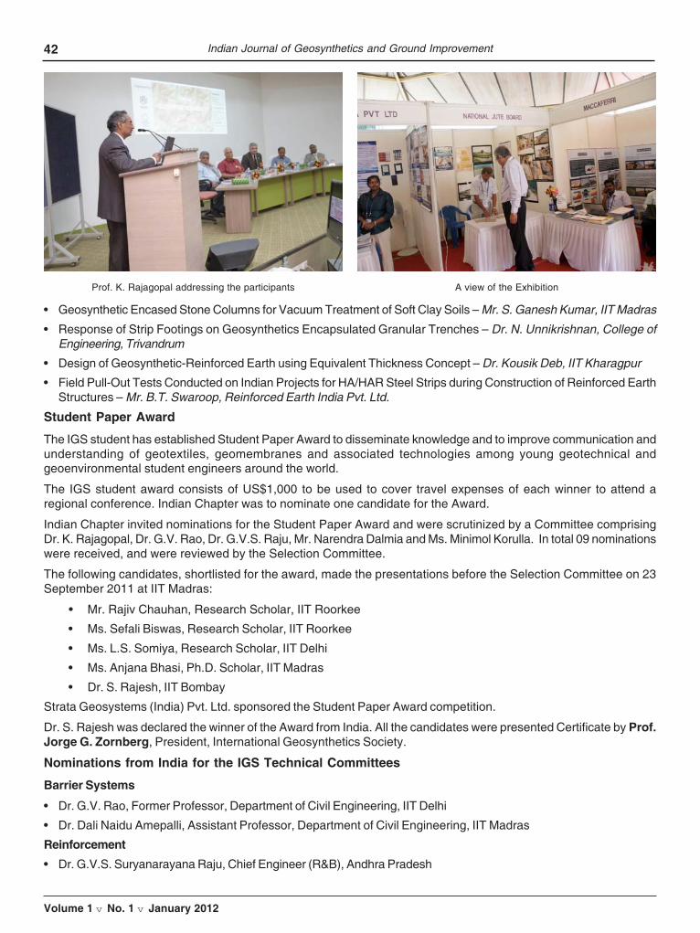
42 Indian Journal of Geosynthetics and Ground Improvement
Volume 1 v No. 1 v January 2012
• Geosynthetic Encased Stone Columns for Vacuum Treatment of Soft Clay Soils – Mr. S. Ganesh Kumar, IIT Madras
• Response of Strip Footings on Geosynthetics Encapsulated Granular Trenches – Dr. N. Unnikrishnan, College ofEngineering, Trivandrum
• Design of Geosynthetic-Reinforced Earth using Equivalent Thickness Concept – Dr. Kousik Deb, IIT Kharagpur
• Field Pull-Out Tests Conducted on Indian Projects for HA/HAR Steel Strips during Construction of Reinforced EarthStructures – Mr. B.T. Swaroop, Reinforced Earth India Pvt. Ltd.
Student Paper Award
The IGS student has established Student Paper Award to disseminate knowledge and to improve communication andunderstanding of geotextiles, geomembranes and associated technologies among young geotechnical andgeoenvironmental student engineers around the world.
The IGS student award consists of US$1,000 to be used to cover travel expenses of each winner to attend aregional conference. Indian Chapter was to nominate one candidate for the Award.
Indian Chapter invited nominations for the Student Paper Award and were scrutinized by a Committee comprisingDr. K. Rajagopal, Dr. G.V. Rao, Dr. G.V.S. Raju, Mr. Narendra Dalmia and Ms. Minimol Korulla. In total 09 nominationswere received, and were reviewed by the Selection Committee.
The following candidates, shortlisted for the award, made the presentations before the Selection Committee on 23September 2011 at IIT Madras:
• Mr. Rajiv Chauhan, Research Scholar, IIT Roorkee
• Ms. Sefali Biswas, Research Scholar, IIT Roorkee
• Ms. L.S. Somiya, Research Scholar, IIT Delhi
• Ms. Anjana Bhasi, Ph.D. Scholar, IIT Madras
• Dr. S. Rajesh, IIT Bombay
Strata Geosystems (India) Pvt. Ltd. sponsored the Student Paper Award competition.
Dr. S. Rajesh was declared the winner of the Award from India. All the candidates were presented Certificate by Prof.Jorge G. Zornberg, President, International Geosynthetics Society.
Nominations from India for the IGS Technical Committees
Barrier Systems
• Dr. G.V. Rao, Former Professor, Department of Civil Engineering, IIT Delhi
• Dr. Dali Naidu Amepalli, Assistant Professor, Department of Civil Engineering, IIT Madras
Reinforcement• Dr. G.V.S. Suryanarayana Raju, Chief Engineer (R&B), Andhra Pradesh
Prof. K. Rajagopal addressing the participants A view of the Exhibition

43
Volume 1 v No. 1 v January 2012
• Mr. Satish Naik, CEO, Best Geotechnics Pvt. Ltd.
• Dr. (Ms.) Gali Madhavi Latha, Associate Professor, Department of Civil Engineering, Indian Institute of Science
Filtration• Mr. Rohit Chaturvedi, Techfab (India) Industries Ltd.
Chapter Achievement Award
The General Body unanimously approved the nomination of Dr. K. Rajagopal for the ChapterAchievement award, keeping in view his contributions to the Geosynthetics in India.
Dr K. Rajagopal is a Professor of Civil Engineering at IIT Madras, Chennai, India andformer Head of the Department during the period 2008-2011. He has been teaching at thisinstitute from 1993. He obtained his Ph.D. from the University of Florida, Gainesville in theyear 1985. He worked as Post-doctoral fellow at Carleton University, Ottawa, Canada during1985-86. Then he joined as a Research Associate in the Military Engineering ResearchGroup of the Royal Military College (RMC), Kingston, Canada. He has closely worked withProf. Richard Bathurst during this period and got initiated into the geosynthetics andreinforced soil structures field during this period. He worked at RMC until joining the facultyof IIT Madras in 1993.
At IIT Madras, he has been involved in guiding several Master’s and Doctoral students in the areas of geosyntheticsand reinforced soil structures. He has been teaching undergraduate and post-graduate courses in geotechnical andgeosynthetics engineering. He has published extensively in several national and international journals. He haswon several best paper awards from Indian Geotechnical Society and Indian Society for Rock Mechanics andTunneling Technology for papers published in respective journals.
He has been a continuous member of International Geosynthetics Society from the year 1988. He has beenworking closely with IGS-India chapter as a member and Executive Council member since 1994. He was co-optedas a council member of the International Geosynthetics Society in May 2010. He was elected as the President of theIGS-India chapter in the year 2010. He is currently an Editorial Board member of Geotextiles and Geomembranesjournal and Indian Geotechnical Journal. He has extensively travelled all over the world to attend various internationalconferences. He has set his foot in all the six inhabited continents of the world.
Formation of Technical Committee on Natural Geosynthetics
The Executive Board of the Society has approved formation of Technical committee on Natural Geosyntheticsunder the Chairmanship of Dr. G.V. Rao.
Other members suggested from India are:
• Dr. K. Rajagopal
• Dr. U.S. Sarma
• Dr. K. Balan
The Board also decided to have representatives from the following countries as members of the Technical Committee:
• Brazil • France • Germany • Myanmar
• Philippines • South Africa • Sri Lanka • Vietnam
Bid for Asian Regional Conference - Geosynthetics Asia’2016
Indian Chapter, in association with the Central Board of Irrigation & Power (CBIP), the Secretariat of the Chapter,would be bidding for hosting the 6th Asian Regional Conference on Geosynthetics.India has the honour of hosteding the First Asian Regional Conference at Bangalore in November 1997.Following is the series of the Asian Regional Conferences on Geosynthetics:
• Second Asian Regional Conference, 2000, Kuala Lumpur, Malaysia• Third Asian Regional Conference, 2004, Seoul, Korea• Fourth Asian Regional Conference, 2008, Shanghai, China
The 5th Asian Regional Conference is scheduled to be held in Bangkok during 10-14 December 2012.
Seminar on “GEOSYNTHETICS INDIA’ 11", 22-24 September 2011, IIT Madras
Dr. K. Rajagopal

44 Indian Journal of Geosynthetics and Ground Improvement
Volume 1 v No. 1 v January 2012
IGS NEWS
Geo-hazards During Earthquakes and Mitigation Measures
The Japanese Geotechnical Society has published “GEO-HAZARDS DURING EARTHQUAKES AND MITIGATIONMEASURES - LESSONS AND RECOMMENDATIONS FROM THE 2011 GREAT EAST JAPAN EARTHQUAKE”.This document is based on experiences with, and lessons from, the disasters that resulted from the 2011 GreatEast Japan Earthquake, 11th March 2011. These documents show several fields where geosynthetics engineeringcan be applied for restoration, reconstruction and new construction. It is noted that the Immediate Past President ofthe IGS, Tatsuoka, F., worked as one of the core members for these documents.
Dr. –Ing Michael Heibaum appointed as 2012 – 2013 Mercer Lecturer
The Mercer Lecture selection committee, chaired by Professor Fumio Tatsuoka and theother members which include Dr Jean-Pierre Giroud, Professor Georg Heerten, ProfessorEnnio Marques Palmeira and Mr. Tim Oliver, has announced that Dr.-Ing. MichaelHeibaum has been appointed as the next lecturer for the 2012 – 2013 Mercer LectureSeries. He will be delivering his presentation on the subject of “Geosynthetics forWaterways and Flood Protection Structures - Controlling the Interaction of Water andSoil”.
The prestigious Mercer Lecture Series was launched in 1992 as a biennial lecture, withthe aim of promoting the co-operation of information exchange between the geotechnical
& geosynthetics engineering professions by giving an eminent practioner the opportunity to undertake a lecture touron the subject of Geosynthetics in Geotechnical Engineering. They are held in honour of the late Dr Brian Mercer,the inventor of geogrids and a strong advocate for innovation, research and development.
Dr Heibaum has many years of experience with the evaluation and application of geosynthetics in hydraulicengineering and currently heads up the Geotechnical Engineering Department of the Federal Waterways Engineeringand Research Institute in Germany. With increasing interest in flood control and waterway engineering associatedwith climate change, the Mercer Lecture committee selected “Waterways and Flood Control” as the theme for the2012- 2013 series and Dr Heibaum will be presenting at the following venues:
• 12th Baltic Sea Conference, Rostock – (31st May – 2nd June 2012)
• ANZ 2012 – Ground Engineering in a Changing World, Melbourne – (15th – 18th July 2012)
• 66th Annual Canadian Geotechnical Conference, Quebec (scheduled for 2013 – dates to be confirmed)
The preceding Mercer Lecture series came to a close this year at the 15th African Regional Conference in Maputo,Mozambique. It was delivered by Professor Junichi Koseki from the University of Tokyo on the subject of “Use ofgeosynthetics to improve seismic performance of earth structures”. Professor Koseki had earlier in the year visitedTexas to deliver the Mercer Lecture to the Geofrontiers Conference. He travelled the day after the tragic Japaneseearthquake on 11th March and delivered his lecture to a standing ovation.
The legacy of the past and current Mercer Lecture lecturers is available on a dedicated website as a resource forthe industry as a whole. Here, visitors to the site can learn more about the conferences that Dr Heibuam will bepresenting at and download the papers of past lecturers. To access this information, visit www.mercerlecture.com.
The Mercer Lecture Series is sponsored by Tensar International Ltd, and endorsed by the International Society forSoil Mechanics and Geotechnical Engineering (ISSMGE) and International Geosynthetics Society (IGS).
If you would like any additional information on the Mercer Lecture Series, contact:
Michelle LeeMarketing ExecutiveTensar International Ltd.,Tel: +44 (0)1254 266 842Email: [email protected]

GUIDELINES FOR AUTHORS
This journal aims to provide a snapshot of the latest research and advances in the field of Geosynthetics. Thejournal addresses what is new, significant and practicable. Journal of Indian Journal of Geosynthetics andGround Improvement is published twice a year (January-June and July-December) by IndianJournals.Com,New Delhi. The Journal has both print and online versions. Being peer-reviewed, the journal publishes originalresearch reports, review papers and communications screened by national and international researchers whoare experts in their respective fields.
The original manuscripts that enhance the level of research and contribute new developments to the geosyntheticssector are encouraged. The work belonging to the fields of Geosynthetics are invited. The journal is expectedto help researchers, technologist and policy makers in the key sector of Geosynthetics to improve communicationand understanding regarding geotextiles, geomembranes and related products among designers, manufacturersand users The manuscripts must be unpublished and should not have been submitted for publication elsewhere.There are no Publication Charges.
1. Guidelines for the preparation of manuscripts for publishing in “Indian Journal of Geosyntheticsand Ground Improvement”
The authors should submit their manuscript in MS-Word (2003/2007) in single column, double line spacing asper the following guidelines. The manuscript should be organized to have Title page, Abstract, Introduction,Material & Methods, Results & Discussion, Conclusion, and Acknowledgement. The manuscript should notexceed 16 pages in double line spacing. (For detailed guidelines, please contact at [email protected])
Submission of Manuscript:
The manuscript must be submitted in doc and pdf to the Editor as an email attachment to [email protected]. Theauthor(s) should send a signed declaration form mentioning that, the matter embodied in the manuscript isoriginal and copyrighted material used during the preparation of the manuscript has been duly acknowledged.The declaration should also carry consent of all the authors for its submission to Journal of IGS (India). It is theresponsibility of corresponding author to secure requisite permission from his or her employer that all paperssubmitted are understood to have received clearance(s) for publication. The authors shall also assign thecopyright of the manuscript to the Indian Chapter of International Geosynthetics Society.
Peer Review Policy:
Review System: Every article is processed by a masked peer review of double blind or by three referees andedited accordingly before publication. The criteria used for the acceptance of article are: contemporary relevance,updated literature, logical analysis, relevance to the global problem, sound methodology, contributionto knowledge and fairly good English. Selection of articles will be purely based on the experts’ views andopinion. Authors will be communicated within Two months from the date of receipt of the manuscript. Theeditorial office will endeavor to assist where necessary with English language editing but authors are herebyrequested to seek local editing assistance as far as possible before submission. Papers with immediate relevancewould be considered for early publication. The possible expectations will be in the case of occasional invitedpapers and editorials, or where a partial or entire issue is devoted to a special theme under the guidance of aGuest Editor.
The Editor-in-Chief may be reached at: [email protected]

PROFILE OF INSTITUTIONAL MEMBERS
Engineering a Better SolutionMaccaferri is a Multidisciplinary Firm involved in Research, Manufacturing, Design, Supply, Execution, Maintainingand Monitoring the complex Civil and Environmental Engineering Application.
We are pleased to introduce our company as one of the Global Market Leaders, providing solutions using HexagonalWoven Double Twisted(DT) wire products, Reinforced Soil Walls, Geosynthetics and its associated productsbeing used within the civil and environment engineering application throughout world and providing compatible andcomprehensive solutions for the construction sector.
Founded in Italy in 1879, the strong management team and reliable product range has created a solid basis for thecompany’s growth. Client’s satisfaction is our main concern, therefore we at MACCAFERRI want to beconsidered as a partner and fully fledged solution provider for our clients.
Our product range includes all sectors of Roads & Highway, Railways, Airports, Ports & Harbour, Water & WasteManagement, and Environment & Disaster Management. Quality products, quick assembly, easy handling, flexibleapplication solutions, economical, and highest safety standards are the main advantages of our systems.
A quick review on our Solutions can show you the strength of our systems for simple and complex applications.
Products Applications Salient FeaturesGabions Gravity Retaining Structures State of art manufacturing unit
Mattressess River Training & Flood Controls Dedicated Research & Development Team
Terramesh Slope Stabilization Project Execution with Consistent Qualityand Efficiency
Paraweb Retaining Soil Wall Extensive Reach & Support Networks
Geogrids Ground Improvement Wide product Portfolio
Geotextile bags, Geo textile tubes Shoreline protection & Coastal Defence
Road Mesh Pavement Strengthening & Rehabilitation
Rock Fall Netting Rock Fall Protection
Geomembranes Land filling and Lining Solutions
If you wish to have a reliable Partner which goes beyond merely supplying products.
Please call our office to speak with one of our MACCAFERRI experts.
To know more about our company and its products you can check our website. www.maccaferri-india.com