ISSN 1392 W displacement of X80 pipeline steel
5
204 ISSN 13921207. MECHANIKA. 2017 Volume 23(2): 204208 Numerical and experimental study on critical crack tip opening displacement of X80 pipeline steel Xiaoben Liu*, Hong Zhang**, Yinshan Han***,Mengying Xia****, Yafeng Ji***** *China University of Petroleum (Beijing), Beijing 102249, China, E-mail: [email protected] **China University of Petroleum (Beijing), Beijing 102249, China, E-mail: [email protected] ***China University of Petroleum (Beijing), Beijing 102249, China, E-mail: [email protected] ****China University of Petroleum (Beijing), Beijing 102249, China, E-mail: [email protected] *****China National Oil and Gas Exploration and Development Corporation, Beijing 100034, China, E-mail: [email protected] http://dx.doi.org/10.5755/j01.mech.23.2.14535 1. Introduction High strength pipeline is the most effective and economical option for long distance transportation of gas re- sources [1]. For instance, X80 steel pipelines have been widely used in the long distance gas pipelines in China [2]. The critical CTOD values of X80 steel serve as a basis in the performance evaluation for these pipelines [3]. The CTOD parameter was proposed in 1963 by Wells [4] to per- form as an engineering fracture parameter for fracture be- yond yielding. The CTOD criterion assumes that fracture occurs When CTOD reaches critical CTOD or exceeds it. For buried pipeline fracture failure, valuable work has been conducted by a series of researchers. Zhang [5] studied the ductile fracture of X65 steel pipes based on ex- tended finite element method. Han [6] studied the effect of constraint on the critical CTOD of X65 steel using a Gurson type void model. Yang [7] studied the fracture toughness of the materials in welded joint of X80 steel. Yan Di [8] devel- oped a new specimen for high-grade pipeline steels CTOA test. Wang [9] conducted quasi-static tests to analyze the crack propagation process and fracture mechanism of X70 and X80 pipeline steels. Oh and his research group derived ductile failure histories of varieties of pipe steels by tensile and 3-point bending tests using GTN model [10-12]. In this study, both experimental and numerical study were conducted for 3-point bending tests of different thickness X80 pipeline steel specimens with initial crack. Based on experiment results, suitable numerical model us- ing the extended finite element method was developed, which can be referenced for the performance evaluation and quality assurance for X80 steel gas pipelines. 2. Experimental study on three-point bending tests of X80 steel specimens The Critical CTOD δc is effected by the thickness t of the specimen, as when t is small, the specimen is close to plane stress state. With increase of t, the specimen changes to plane strain state gradually. So X80 steel specimens with different thicknesses were considered in this study. According to GB/T 21143-2007 [13], the maxi- mum force Pc and the plastic component of the crack mouth opening displacement Vp. both can be derived by the meas- ured P-V curve of tested specimen, as shown in Fig. 1. The detailed dimension parameters of the specimen are illus- trated in Fig. 2. And based on Eq. (1), the critical CTOD δc can be easily determined. V P c V p A A p V e V g Force (P) Fig. 1 P-V curve and definition of VP V δ W-a W a z O Fig. 2 Dimension of CTOD specimen 2 2 15 1 04 2 06 04 p . s . W aV PS a f W E .a .W z WB , (1) where δ is crack tip opening displacement; P is applied force; S is span between outer loading points in three point bend test; W is effective width of test specimen; Vp is plastic component of crack mouth opening displacement; E is elas- tic modules; σs is yield strength; a is original crack length; z is distance of the crack opening gauge location above the
Transcript of ISSN 1392 W displacement of X80 pipeline steel

204
ISSN 13921207. MECHANIKA. 2017 Volume 23(2): 204208
Numerical and experimental study on critical crack tip opening
displacement of X80 pipeline steel
Xiaoben Liu*, Hong Zhang**, Yinshan Han***,Mengying Xia****, Yafeng Ji***** *China University of Petroleum (Beijing), Beijing 102249, China, E-mail: [email protected]
**China University of Petroleum (Beijing), Beijing 102249, China, E-mail: [email protected]
***China University of Petroleum (Beijing), Beijing 102249, China, E-mail: [email protected]
****China University of Petroleum (Beijing), Beijing 102249, China, E-mail: [email protected]
*****China National Oil and Gas Exploration and Development Corporation, Beijing 100034, China,
E-mail: [email protected]
http://dx.doi.org/10.5755/j01.mech.23.2.14535
1. Introduction
High strength pipeline is the most effective and
economical option for long distance transportation of gas re-
sources [1]. For instance, X80 steel pipelines have been
widely used in the long distance gas pipelines in China [2].
The critical CTOD values of X80 steel serve as a basis in
the performance evaluation for these pipelines [3]. The
CTOD parameter was proposed in 1963 by Wells [4] to per-
form as an engineering fracture parameter for fracture be-
yond yielding. The CTOD criterion assumes that fracture
occurs When CTOD reaches critical CTOD or exceeds it.
For buried pipeline fracture failure, valuable work
has been conducted by a series of researchers. Zhang [5]
studied the ductile fracture of X65 steel pipes based on ex-
tended finite element method. Han [6] studied the effect of
constraint on the critical CTOD of X65 steel using a Gurson
type void model. Yang [7] studied the fracture toughness of
the materials in welded joint of X80 steel. Yan Di [8] devel-
oped a new specimen for high-grade pipeline steels CTOA
test. Wang [9] conducted quasi-static tests to analyze the
crack propagation process and fracture mechanism of X70
and X80 pipeline steels. Oh and his research group derived
ductile failure histories of varieties of pipe steels by tensile
and 3-point bending tests using GTN model [10-12].
In this study, both experimental and numerical
study were conducted for 3-point bending tests of different
thickness X80 pipeline steel specimens with initial crack.
Based on experiment results, suitable numerical model us-
ing the extended finite element method was developed,
which can be referenced for the performance evaluation and
quality assurance for X80 steel gas pipelines.
2. Experimental study on three-point bending tests of
X80 steel specimens
The Critical CTOD δc is effected by the thickness t
of the specimen, as when t is small, the specimen is close to
plane stress state. With increase of t, the specimen changes
to plane strain state gradually. So X80 steel specimens with
different thicknesses were considered in this study.
According to GB/T 21143-2007 [13], the maxi-
mum force Pc and the plastic component of the crack mouth
opening displacement Vp. both can be derived by the meas-
ured P-V curve of tested specimen, as shown in Fig. 1. The
detailed dimension parameters of the specimen are illus-
trated in Fig. 2. And based on Eq. (1), the critical CTOD δc
can be easily determined.
V
Pc
Vp
A
Ap
Ve
Vg
Fo
rce
(P)
Fig. 1 P-V curve and definition of VP
V
δ
W-aW
a
z
O
Fig. 2 Dimension of CTOD specimen
22
1 5
1 0 4
2 0 6 0 4
p
.
s
. W a VPS af
W E . a . W zWB
, (1)
where δ is crack tip opening displacement; P is applied
force; S is span between outer loading points in three point
bend test; W is effective width of test specimen; Vp is plastic
component of crack mouth opening displacement; E is elas-
tic modules; σs is yield strength; a is original crack length; z
is distance of the crack opening gauge location above the

205
surface of the specimen; B is specimen thickness; μ is Pois-
son’s ratio; f is a mathematical function of (a/W).
In this study, the length and width of the specimen
are 120 mm and 25 mm, respectively. And two specimen
thicknesses, 12.5 mm and 7 mm, are considered. The initial
machined notch of the specimen is 5 mm, and the fatigue
precrack is generated by the MTS 632.03C-20 High Fre-
quency Fatigue Tester. The total original crack length
should be between 0.45W and 0.70W for all specimens [13].
In the process, the loading frequency is 10 Hz, and the load-
ing rate is 0.0167 mm/s.
Fig. 3 Three Point Bending Testing
0 1 2 3 40
3
6
9
12
15
Load
P (
KN)
Crack mouth opening displacement V(mm)
a
0 1 2 3 40
2
4
6
8
10
Load
P (
KN)
Crack mouth opening displacement V(mm)
b
Fig. 4 The P-V curves for all specimens: a - B = 12.5 mm;
b - B = 7 mm
The 3 point bending tests were conducted on the
prepared specimens with the P-V curve measured by the
computer, as shown in Fig. 3. Totally, six specimens were
tested, and the P-V curves are shown in Fig. 4. The red
points represents the maximum applied forces (Pc), and the
Plastic crack mouth opening displacements (Vp) can also ob-
tained from the figure, as listed in Table 1. Results show
that, for the same pipe material, Vp was influenced obviously
by the specimen thickness B, and if B is smaller, Vp is larger.
After the test, the specimens were technically
treated to make the fracture surface turn blue, and the color
of the initial crack would be a little lighter. The colored frac-
ture surfaces are shown in Fig. 5. It can be derived that for
both kinds of specimens, the crack propagation occurs first
in the center area of the specimen. For specimens with thin-
ner thickness, the propagation crack length is linearly dis-
tributed from center to edge. For specimens with thicker
thickness, the crack length in the center segment is nearly
the same, and linearly attenuated from center to edge.
a
b
Fig. 5 Fracture surface of the specimens: a - B = 12.5 mm;
b - B = 7 mm
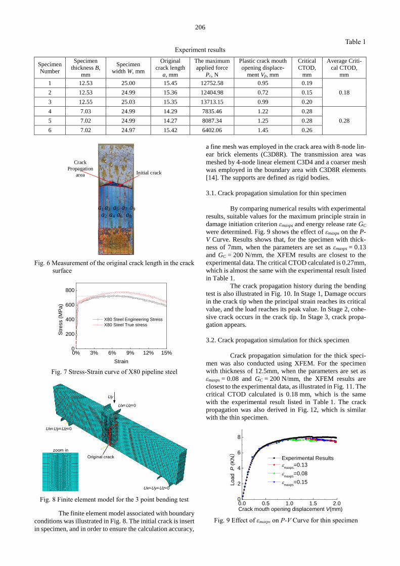
The original crack length of the specimen can be
calculated by Eq. (2), in which the nine crack lengths can be
measured as shown in Fig. 6. Eventually, by the measured
parameters, the critical CTOD can be calculated, as listed in
Table 1. The results show that the thicker specimens have
smaller critical CTOD.
1 90 2 3 4 5 6 7 8
1
8 2
a aa a a a a a a a
. (2)
3. Numerical simulation and results
In this study, the crack propagation of the X80 steel
specimens is simulated using by ABAQUS XFEM software
package. It is proven to be an effective way to study the duc-
tile fracture mechanism of pipe steels [5]. The true stress-
strain curve of the tested X80 steel was used in the model,
as shown in Fig. 7. For X80 pipeline steel with the occur-
rence of ductile failure, the maximum principal strain crite-
rion is used for damage initiation of the crack, and the ex-
ponential response is used for damage evolution.
206
Table 1 Experiment results
Specimen
Number
Specimen
thickness B,
mm
Specimen
width W, mm
Original
crack length
a, mm
The maximum
applied force
Pc, N
Plastic crack mouth
opening displace-
ment Vp, mm
Critical
CTOD,
mm
Average Criti-
cal CTOD,
mm
1 12.53 25.00 15.45 12752.58 0.95 0.19
0.18 2 12.53 24.99 15.36 12404.98 0.72 0.15
3 12.55 25.03 15.35 13713.15 0.99 0.20
4 7.03 24.99 14.29 7835.46 1.22 0.28
0.28 5 7.02 24.99 14.27 8087.34 1.25 0.28
6 7.02 24.97 15.42 6402.06 1.45 0.26
a1
a2
a3
a4
a5
a6
a7
a8
a9
Crack
Propagation
area Initial crack
Fig. 6 Measurement of the original crack length in the crack
surface
0% 3% 6% 9% 12% 15%0
200
400
600
800
Str
ess (
MP
a)
Strain
X80 Steel Engineering Stress
X80 Steel True stress
Fig. 7 Stress-Strain curve of X80 pipeline steel
Ux=Uz=0
Ux=Uy=Uz=0
Original crack
zoom in
Ux=Uy=Uz=0
Uy
Fig. 8 Finite element model for the 3 point bending test
The finite element model associated with boundary
conditions was illustrated in Fig. 8. The initial crack is insert
in specimen, and in order to ensure the calculation accuracy,
a fine mesh was employed in the crack area with 8-node lin-
ear brick elements (C3D8R). The transmission area was
meshed by 4-node linear element C3D4 and a coarser mesh
was employed in the boundary area with C3D8R elements
[14]. The supports are defined as rigid bodies.
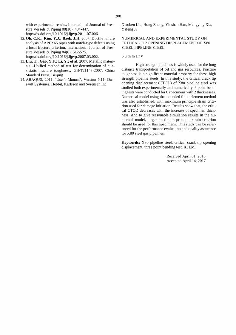
3.1. Crack propagation simulation for thin specimen
By comparing numerical results with experimental
results, suitable values for the maximum principle strain in
damage initiation criterion εmaxps and energy release rate GC
were determined. Fig. 9 shows the effect of εmaxps on the P-
V Curve. Results shows that, for the specimen with thick-
ness of 7mm, when the parameters are set as εmaxps = 0.13
and GC = 200 N/mm, the XFEM results are closest to the
experimental data. The critical CTOD calculated is 0.27mm,
which is almost the same with the experimental result listed
in Table 1.
The crack propagation history during the bending
test is also illustrated in Fig. 10. In Stage 1, Damage occurs
in the crack tip when the principal strain reaches its critical
value, and the load reaches its peak value. In Stage 2, cohe-
sive crack occurs in the crack tip. In Stage 3, crack propa-
gation appears.
3.2. Crack propagation simulation for thick specimen
Crack propagation simulation for the thick speci-
men was also conducted using XFEM. For the specimen
with thickness of 12.5mm, when the parameters are set as
εmaxps = 0.08 and GC = 200 N/mm, the XFEM results are
closest to the experimental data, as illustrated in Fig. 11. The
critical CTOD calculated is 0.18 mm, which is the same
with the experimental result listed in Table 1. The crack
propagation was also derived in Fig. 12, which is similar
with the thin specimen.
0.0 0.5 1.0 1.5 2.00
2
4
6
8
Experimental Results
maxps
=0.13
maxps
=0.08
maxps
=0.15Load
P (
KN)
Crack mouth opening displacement V(mm)
Fig. 9 Effect of εmaxps on P-V Curve for thin specimen

207
Fig. 10 The crack propagation history for thin specimen
0.0 0.5 1.0 1.5 2.00
3
6
9
Experimental Results
XFEM Results
Load P
(KN
)
Crack mouth opening displacement V(mm)
Fig. 11 Comparison of the numerical and experimental re-
sults for thick specimen
It can be obtained that, although the simulated re-
sults is quite accurate comparing with the experimental re-
sults. But the maximum principle strain criterion εmaxps is
different for the specimens with different thicknesses. So
when conducting a numerical analysis for CTOD calculat-
ing, the failure criterion must be validated by suitable exper-
imental results.
Fig. 12 The crack propagation history for thick specimen
4. Conclusions
In this study, the critical CTOD for X80 pipeline
steel was studied. 3-point bending tests were conducted for
two specimens with different thickness. Based on the exper-
imental results, reasonable numerical models based on the
extended finite element method was established. Results
show that, the critical CTOD δcrit decreases with the increase
of specimen thickness B; the maximum principle strain cri-
terion for damage initiation εmaxps is suitable for the ductile
crack simulation of X80 pipeline steel, but εmaxps decreases
with the increase of specimen thickness. This study can be
referenced for the performance evaluation and quality assur-
ance for X80 steel pipelines.
Acknowledgements
The financial support provided by the CNPC grand
science and technology special project “Research on the key
technology of the third generation large gas pipeline engi-
neering project” under Grant No. 2012E-2801-01 is grate-
fully acknowledged.
References
1. Yu, Z.F.; Wang, G.L.; Shi, H.; et al. 2008. Guideline
for strain-based design in seismic area and active fault
crossing of the second west-east natural gas transporta-
tion pipeline project, Q/SY GJX 0136-2008 Beijing: Pe-
troleum Industry Press.
2. Liu, X.B.; Zhang, H.; Chen, Y.F. 2015. Strain predic-
tion of X80 steel pipeline at strike-slip fault under com-
pression combined with bending, in: ASME 2015 Pres-
sure Vessels & Piping Conference.
3. Zhu, X.K.; Joyce, J.A. 2012. Review of fracture tough-
ness (g, k, j, ctod, ctoa) testing and standardization, En-
gineering Fracture Mechanics 85: 1-46.
http://dx.doi.org/10.1016/j.engfracmech.2012.02.001.
4. Wells, AA. 1963. Application of fracture mechanics at
and beyond general yielding. British Welding Journal
10: 563-570.
5. Zhang, B.; Ye, C.; Liang, B.; et al. 2014. Ductile fail-
ure analysis and crack behavior of X65 buried pipes us-
ing extended finite element method, Engineering Failure
Analysis 45(8): 26-40.
http://dx.doi.org/10.1016/j.engfailanal.2014.06.009.
6. Han, K.; Shuai, J.; Deng, X.; et al. 2014. The effect of
constraint on CTOD fracture toughness of API X65
steel, Engineering Fracture Mechanics 124: 167-181.
http://dx.doi.org/10.1016/j.engfracmech.2014.04.014.
7. Yang, X.B.; Zhuang, Z.; You, X.C.; et al. 2008. Dy-
namic fracture study by an experiment/simulation
method for rich gas transmission X80 steel pipelines,
Engineering Fracture Mechanics 75(18): 5018-5028.
http://dx.doi.org/10.1016/j.engfracmech.2008.06.032.
8. Di, Y.; Shuai, J.; Wang, J.; Tu, S. 2015. A new speci-
men for high-grade pipeline steels CTOA test, Engineer-
ing Fracture Mechanics 148: 203-212.
http://dx.doi.org/10.1016/j.engfracmech.2015.06.088.
9. Wang, J.Q.; Shuai J. 2012. Measurement and analysis
of crack tip opening angle in pipeline steels, Engineering
Fracture Mechanics 79: 36-49.
http://dx.doi.org/10.1016/j.engfracmech.2011.09.018.
10. Oh, C.S.; Kim, N.H.; Kim, Y.J.; et al. 2011 A finite
element ductile failure simulation method using stress-
modified fracture strain model [J], Engineering Fracture
Mechanics 78(1): 124-137.
http://dx.doi.org/10.1016/j.engfracmech.2010.10.004.
11. Kim, N.H.; Oh, C.S.; Kim, Y.J.; et al. 2011 Compari-
son of fracture strain based ductile failure simulation
208
with experimental results, International Journal of Pres-
sure Vessels & Piping 88(10): 434-447.
http://dx.doi.org/10.1016/j.ijpvp.2011.07.006.
12. Oh, C.K.; Kim, Y.J.; Baek, J.H. 2007. Ductile failure
analysis of API X65 pipes with notch-type defects using
a local fracture criterion, International Journal of Pres-
sure Vessels & Piping 84(8): 512-525.
http://dx.doi.org/10.1016/j.ijpvp.2007.03.002.
13. Liu, T.; Gao, Y.F.; Li, Y.; et al. 2007. Metallic materi-
als –Unified method of test for determination of qua-
sistatic fracture toughness, GB/T21143-2007, China
Standard Press, Beijing.
14. ABAQUS, 2011. ‘User's Manual’, Version 6.11. Das-
sault Systemes. Hebbit, Karlsson and Sorensen Inc.
Xiaoben Liu, Hong Zhang, Yinshan Han, Mengying Xia,
Yafeng Ji
NUMERICAL AND EXPERIMENTAL STUDY ON
CRITICAL TIP OPENING DISPLACEMENT OF X80
STEEL PIPELINE STEEL
S u m m a r y
High strength pipelines is widely used for the long
distance transportation of oil and gas resources. Fracture
toughness is a significant material property for these high
strength pipeline steels. In this study, the critical crack tip
opening displacement (CTOD) of X80 pipeline steel was
studied both experimentally and numerically. 3 point bend-
ing tests were conducted for 6 specimens with 2 thicknesses.
Numerical model using the extended finite element method
was also established, with maximum principle strain crite-
rion used for damage initiation. Results show that, the criti-
cal CTOD decreases with the increase of specimen thick-
ness. And to give reasonable simulation results in the nu-
merical model, larger maximum principle strain criterion
should be used for thin specimens. This study can be refer-
enced for the performance evaluation and quality assurance
for X80 steel gas pipelines.
Keywords: X80 pipeline steel, critical crack tip opening
displacement, three point bending test, XFEM.
Received April 01, 2016
Accepted April 14, 2017