ISS EVA procedure - SpaceRef · ˇ ˘ ˇˆ ˙ ˝ ˙˛˛˚ National Aeronautics and Space...
411
JSC-48538 International Space Station ISS EVA Checklist ISS-7A Mission Operations Directorate Operations Division April 27, 2001
Transcript of ISS EVA procedure - SpaceRef · ˇ ˘ ˇˆ ˙ ˝ ˙˛˛˚ National Aeronautics and Space...

�
���������
� �
��������������� ����������������� ����
������
��������������������� ������������������������
�����������
National Aeronautics andSpace Administration
Lyndon B. Johnson Space CenterHouston, Texas
������������������ ���������������� JSC-48538�
�����������������������
�� ���������
����
����������������
APPROVED BY:
����������������������������������������������������������� ���!���
������������������������������ ������������������������������� "���������#������ ������������� $����%&��' �(��)�� $����%&��������(��)��
��������������������������������������������$��*��*����
� ���+����������
ACCEPTED BY:
����������������������������������������������#,���'��-)���� �����!���
',����#)�������)������,��#��.�!)������#��������.��,�������� ����������������+������������/� ��+�0��
������������������ ���������������� JSC-48538�
27 APR 01 ISS EVAii
�
1�#���������,��.����2��!3�
+"3� �)����������������
� � �
�

� - Omit from flight book
27 APR 01 iii ISS EVA
�����������������������
�� ���������
LIST OF EFFECTIVE PAGES
27 APR 01
Sign Off...........................� 27 APR 01ii ......................................� 27 APR 01iii .....................................� 27 APR 01iv .....................................� 27 APR 01v......................................� 27 APR 01vi .....................................� 27 APR 01vii ....................................� 27 APR 01viii ...................................� 27 APR 01ix ..................................... 27 APR 01x...................................... 27 APR 01xi ..................................... 27 APR 01xii .................................... 27 APR 01xiii ................................... 27 APR 01xiv ................................... 27 APR 01xv .................................... 27 APR 01xvi ................................... 27 APR 011...................................... 25 APR 012...................................... 25 APR 013...................................... 16 APR 014...................................... 16 APR 015...................................... 25 APR 016...................................... 25 APR 017...................................... 25 APR 018...................................... 25 APR 019...................................... 25 APR 0110.................................... 25 APR 0111.................................... 23 APR 0112.................................... 26 APR 0113.................................... 11 APR 0114.................................... 11 APR 0115.................................... 25 APR 0116.................................... 25 APR 0117.................................... 08 MAR 0118.................................... 08 MAR 0119.................................... 08 FEB 0120.................................... 08 FEB 0121.................................... 14 FEB 0122.................................... 26 APR 0123.................................... 14 FEB 0124.................................... 14 FEB 0125.................................... 18 OCT 0026.................................... 18 OCT 0027.................................... 01 FEB 01
28 ................................... 26 APR 0129 ................................... 17 APR 0130 ................................... 17 APR 0131 ................................... 12 APR 0132 ................................... 26 APR 0133 ................................... 08 MAR 0134 ................................... 08 MAR 0135 ................................... 25 APR 0136 ................................... 25 APR 0137 ................................... 24 FEB 0138 ................................... 24 FEB 0139 ................................... 24 FEB 0140 ................................... 24 FEB 0141 ................................... 24 FEB 0142 ................................... 26 APR 0143 ................................... 14 FEB 0144 ................................... 14 FEB 0145 ................................... 14 FEB 0146 ................................... 14 FEB 0147 ................................... 14 FEB 0148 ................................... 14 FEB 0149 ................................... 14 FEB 0150 ................................... 14 FEB 0151 ................................... 24 JAN 0152 ................................... 24 JAN 0153 ................................... 11 APR 0154 ................................... 11 APR 0155 ................................... 28 MAR 0156 ................................... 28 MAR 0157 ................................... 28 MAR 0158 ................................... 28 MAR 0159 ................................... 28 MAR 0160 ................................... 26 APR 0161 ................................... 11 APR 0162 ................................... 11 APR 0163 ................................... 11 APR 0164 ................................... 26 APR 0165 ................................... 01 FEB 0166 ................................... 26 APR 0167 ................................... 14 FEB 0168 ................................... 26 APR 0169 ................................... 23 APR 0170 ................................... 26 APR 01
27 APR 01 ISS EVAiv
71.................................... 25 APR 0172.................................... 25 APR 0173.................................... 25 APR 0174.................................... 25 APR 0175.................................... 25 APR 0176.................................... 26 APR 0177.................................... 24 APR 0178.................................... 24 APR 0179.................................... 24 APR 0180.................................... 24 APR 0181.................................... 24 APR 0182.................................... 24 APR 0183.................................... 24 APR 0184.................................... 24 APR 0185.................................... 16 APR 0186.................................... 26 APR 0187.................................... 23 APR 0188.................................... 23 APR 0189.................................... 23 APR 0190.................................... 26 APR 0191.................................... 24 JAN 0192.................................... 24 JAN 0193.................................... 24 JAN 0194.................................... 26 APR 0195.................................... 25 APR 0196.................................... 25 APR 0197.................................... 03 NOV 0098.................................... 26 APR 0199.................................... 25 APR 01100.................................. 25 APR 01101.................................. 25 APR 01102.................................. 26 APR 01103.................................. 25 APR 01104.................................. 26 APR 01105.................................. 25 APR 01106.................................. 26 APR 01107.................................. 25 APR 01108.................................. 26 APR 01109.................................. 25 APR 01110.................................. 25 APR 01111.................................. 24 FEB 01112.................................. 24 FEB 01113.................................. 24 FEB 01114.................................. 24 FEB 01115.................................. 14 FEB 01116.................................. 26 APR 01117.................................. 25 APR 01118.................................. 25 APR 01119.................................. 14 FEB 01120.................................. 26 APR 01121.................................. 14 FEB 01
122 ................................. 14 FEB 01123 ................................. 06 FEB 01124 ................................. 06 FEB 01125 ................................. 14 FEB 01126 ................................. 26 APR 01127 ................................. 08 FEB 01128 ................................. 26 APR 01129 ................................. 08 FEB 01130 ................................. 26 APR 01131 ................................. 08 FEB 01132 ................................. 26 APR 01133 ................................. 09 APR 01134 ................................. 09 APR 01135 ................................. 09 APR 01136 ................................. 26 APR 01137 ................................. 14 FEB 01138 ................................. 14 FEB 01139 ................................. 09 APR 01140 ................................. 09 APR 01141 ................................. 14 FEB 01142 ................................. 26 APR 01143 ................................. 14 FEB 01144 ................................. 26 APR 01145 ................................. 01 FEB 01146 ................................. 01 FEB 01147 ................................. 11 APR 01148 ................................. 26 APR 01149 ................................. 08 FEB 01150 ................................. 26 APR 01151 ................................. 01 FEB 01152 ................................. 01 FEB 01153 ................................. 01 FEB 01154 ................................. 26 APR 01155 ................................. 25 APR 01156 ................................. 25 APR 01157 ................................. 10 APR 01158 ................................. 26 APR 01159 ................................. 24 APR 01160 ................................. 26 APR 01161 ................................. 15 FEB 01162 ................................. 15 FEB 01163 ................................. 14 FEB 01164 ................................. 26 APR 01165 ................................. 14 FEB 01166 ................................. 14 FEB 01167 ................................. 08 FEB 01168 ................................. 08 FEB 01169 ................................. 08 FEB 01170 ................................. 26 APR 01171 ................................. 08 FEB 01172 ................................. 26 APR 01

27 APR 01 ISS EVAv
173.................................. 08 FEB 01174.................................. 26 APR 01175.................................. 18 APR 01176.................................. 18 APR 01177.................................. 08 FEB 01178.................................. 26 APR 01179.................................. 24 FEB 01180.................................. 26 APR 01181.................................. 25 APR 01182.................................. 25 APR 01183.................................. 25 APR 01184.................................. 25 APR 01185.................................. 25 APR 01186.................................. 26 APR 01187.................................. 14 FEB 01188.................................. 14 FEB 01189.................................. 14 FEB 01190.................................. 26 APR 01191.................................. 25 APR 01192.................................. 25 APR 01193.................................. 23 APR 01194.................................. 23 APR 01195.................................. 23 APR 01196.................................. 23 APR 01197.................................. 24 APR 01198.................................. 24 APR 01199.................................. 24 APR 01200.................................. 24 APR 01201.................................. 25 APR 01202.................................. 25 APR 01203.................................. 25 APR 01204.................................. 25 APR 01205.................................. 23 APR 01206.................................. 23 APR 01207.................................. 23 APR 01208.................................. 26 APR 01209.................................. 23 APR 01210.................................. 23 APR 01211.................................. 23 APR 01212.................................. 26 APR 01213.................................. 20 APR 01214.................................. 20 APR 01215.................................. 23 APR 01216.................................. 23 APR 01217.................................. 23 APR 01218.................................. 26 APR 01219.................................. 23 APR 01220.................................. 23 APR 01221.................................. 23 APR 01222.................................. 23 APR 01223.................................. 23 APR 01
224 ................................. 23 APR 01225 ................................. 23 APR 01226 ................................. 26 APR 01227 ................................. 23 APR 01228 ................................. 23 APR 01229 ................................. 23 APR 01230 ................................. 26 APR 01231 ................................. 25 APR 01232 ................................. 25 APR 01233 ................................. 24 APR 01234 ................................. 24 APR 01235 ................................. 24 APR 01236 ................................. 26 APR 01237 ................................. 25 APR 01238 ................................. 25 APR 01239 ................................. 25 APR 01240 ................................. 25 APR 01241 ................................. 24 APR 01242 ................................. 24 APR 01243 ................................. 24 APR 01244 ................................. 24 APR 01245 ................................. 24 APR 01246 ................................. 26 APR 01247 ................................. 14 FEB 01248 ................................. 26 APR 01249 ................................. 06 FEB 01250 ................................. 06 FEB 01251 ................................. 06 FEB 01252 ................................. 06 FEB 01253 ................................. 06 FEB 01254 ................................. 06 FEB 01255 ................................. 06 FEB 01256 ................................. 06 FEB 01257 ................................. 06 FEB 01258 ................................. 06 FEB 01259 ................................. 06 FEB 01260 ................................. 06 FEB 01261 ................................. 06 FEB 01262 ................................. 26 APR 01263 ................................. 16 APR 01264 ................................. 16 APR 01265 ................................. 11 APR 01266 ................................. 11 APR 01267 ................................. 11 APR 01268 ................................. 11 APR 01269 ................................. 24 FEB 01270 ................................. 24 FEB 01271 ................................. 24 FEB 01272 ................................. 24 FEB 01273 ................................. 24 FEB 01274 ................................. 26 APR 01

27 APR 01 ISS EVAvi
275.................................. 25 APR 01276.................................. 25 APR 01277.................................. 23 APR 01278.................................. 26 APR 01279.................................. 25 APR 01280.................................. 25 APR 01281.................................. 25 APR 01282.................................. 26 APR 01283.................................. 09 APR 01284.................................. 09 APR 01285.................................. 08 FEB 01286.................................. 26 APR 01287.................................. 25 APR 01288.................................. 25 APR 01289.................................. 08 FEB 01290.................................. 26 APR 01291.................................. 10 APR 01292.................................. 10 APR 01293.................................. 10 APR 01294.................................. 10 APR 01295.................................. 10 APR 01296.................................. 26 APR 01297.................................. 16 APR 01298.................................. 16 APR 01299.................................. 16 APR 01300.................................. 16 APR 01301.................................. 16 APR 01302.................................. 16 APR 01303.................................. 16 APR 01304.................................. 16 APR 01305.................................. 14 FEB 01306.................................. 14 FEB 01307.................................. 24 APR 01308.................................. 24 APR 01309.................................. 24 APR 01310.................................. 26 APR 01311.................................. 25 APR 01312.................................. 25 APR 01313.................................. 23 APR 01314.................................. 26 APR 01315.................................. 14 FEB 01316.................................. 26 APR 01317.................................. 19 OCT 00318.................................. 26 APR 01319.................................. 14 FEB 01320.................................. 26 APR 01321.................................. 26 APR 01322.................................. 26 APR 01323.................................. 18 OCT 00324.................................. 26 APR 01325.................................. 25 APR 01
326 ................................. 25 APR 01327 ................................. 05 MAR 01328 ................................. 26 APR 01329 ................................. 24 APR 01330 ................................. 26 APR 01331 ................................. 05 MAR 01332 ................................. 26 APR 01333 ................................. 16 APR 01334 ................................. 16 APR 01335 ................................. 05 MAR 01336 ................................. 26 APR 01337 ................................. 05 MAR 01338 ................................. 26 APR 01339 ................................. 11 APR 01340 ................................. 26 APR 01341 ................................. 11 APR 01342 ................................. 26 APR 01343 ................................. 11 APR 01344 ................................. 26 APR 01345 ................................. 05 MAR 01346 ................................. 26 APR 01347 ................................. 05 MAR 01348 ................................. 26 APR 01349 ................................. 05 MAR 01350 ................................. 26 APR 01351 ................................. 05 MAR 01352 ................................. 26 APR 01353 ................................. 05 MAR 01354 ................................. 26 APR 01355 ................................. 05 MAR 01356 ................................. 26 APR 01357 ................................. 11 APR 01358 ................................. 26 APR 01359 ................................. 05 MAR 01360 ................................. 26 APR 01361 ................................. 05 MAR 01362 ................................. 26 APR 01363 ................................. 05 MAR 01364 ................................. 26 APR 01365 ................................. 05 MAR 01366 ................................. 26 APR 01367 ................................. 16 APR 01368 ................................. 16 APR 01369 ................................. 26 APR 01370 ................................. 26 APR 01371 ................................. 11 APR 01372 ................................. 26 APR 01373 ................................. 12 MAR 01374 ................................. 26 APR 01375 ................................. 12 MAR 01376 ................................. 26 APR 01
27 APR 01 ISS EVAvii
377.................................. 12 MAR 01378.................................. 26 APR 01379.................................. 12 MAR 01380.................................. 26 APR 01381.................................. 12 MAR 01382.................................. 26 APR 01383.................................. 25 APR 01384.................................. 25 APR 01385.................................. 14 FEB 01386.................................. 26 APR 01387.................................. 01 MAR 01388.................................. 26 APR 01389.................................. 18 APR 01390.................................. 18 APR 01391.................................. 18 APR 01392.................................. 18 APR 01393.................................. 08 FEB 01394.................................. 26 APR 01

27 APR 01 ISS EVAviii
This Page Intentionally Blank

27 APR 01 ISS EVAix
CONTENTS
10.2 PSI OPS........................................................................................................ 1MASK PREBREATHE INITIATE (10 MINUTES) ................................................... 3ISS AIRLOCK 10.2 PSIA OPERATIONS INITIATION........................................... 5MASK PREBREATHE TERMINATE (10 MINUTES) ............................................. 11ISS AIRLOCK 10.2 PSIA OPERATIONS TERMINATION ..................................... 13
AIRLOCK CONFIG ............................................................................................... 15AIRLOCK PREP FOR EVA OPS (30 MINUTES) .................................................. 17EMU SWAP (30 MINUTES) .................................................................................. 19LTA RESTRAINT STRAP REMOVAL (15 MINUTES) ........................................... 21LTA RESTRAINT STRAP INSTALLATION (15 MINUTES) ................................... 23EMU RESIZE (30 MINUTES)................................................................................ 25EMU METOX INSTALLATION (10 MINUTES) ...................................................... 27EMU WATER RECHARGE BAG DUMP (20 MINUTES) ....................................... 29EMU WATER RECHARGE BAG FILL (40 MINUTES) .......................................... 31AIRLOCK DECONFIG POST EVA (30 MINUTES)................................................ 33
CHECKOUTS ....................................................................................................... 35EMU CHECKOUT................................................................................................. 37COMM CHECK (30 MINUTES)............................................................................. 43EVA COMM DECONFIG (5 MINUTES)................................................................. 51REBA POWERED HARDWARE CHECKOUT (15 MINUTES) .............................. 53EMU TO AIRLOCK INTERFACE CHECK (30 MINUTES)..................................... 55SAFER CHECKOUT (30 MINUTES)..................................................................... 61SAFER CHECKOUT RESULTS............................................................................ 65PGT CHECKOUT ................................................................................................. 67PGT STANDARD SETTINGS ............................................................................... 69
EVA PREP............................................................................................................ 71EQUIPMENT LOCK PREP (90 MINUTES) ........................................................... 73EVA PREP (170 MINUTES).................................................................................. 77EMU PURGE ........................................................................................................ 85EMU PREBREATHE............................................................................................. 87EVA COMM CONFIG (5 MINUTES) ..................................................................... 91
EMU STATUS....................................................................................................... 95EMU STATUS....................................................................................................... 97
DEPRESS/REPRESS........................................................................................... 99CREWLOCK DEPRESS (30 MINUTES) ............................................................... 101POST DEPRESS (5 MINUTES)............................................................................ 103PRE REPRESS (5 MINUTES) .............................................................................. 105CREWLOCK REPRESS (10 MINUTES) ............................................................... 107
POST EVA............................................................................................................ 109POST EVA (80 MINUTES).................................................................................... 111SAFER STOW (10 MINUTES) .............................................................................. 115

27 APR 01 ISS EVAx
EMU MAINTENANCE/RECHARGE ...................................................................... 117EMU POWERUP .................................................................................................. 119LCVG WATER FILL (30 MINUTES) ...................................................................... 121EMU WATER RECHARGE................................................................................... 123EMU METOX/BATTERY REPLACEMENT (20 MINUTES) ................................... 125EMU METOX REMOVAL (5 MINUTES)................................................................ 127REBA INSTALLATION (10 MINUTES).................................................................. 129REBA REMOVAL.................................................................................................. 131BSA BATTERY RECHARGE INITIATE (20 MINUTES)......................................... 133BSA BATTERY RECHARGE TERMINATE (10 MINUTES)................................... 137IN-SUIT EMU BATTERY RECHARGE INITIATE (10 MINUTES) .......................... 139IN-SUIT EMU BATTERY RECHARGE TERMINATE (10 MINUTES) .................... 141EMU POWERDOWN ............................................................................................ 143METOX REGENERATION INITIATE (10 MINUTES) ............................................ 145METOX REGENERATION TERMINATE (10 MINUTES) ...................................... 147METOX REGENERATION STANDBY (5 MINUTES) ............................................ 149HELMET LIGHT BULB CHANGEOUT (15 MINUTES) .......................................... 151EMU CLEANING MATRIX .................................................................................... 153
EMU CONTINGENCY PROCEDURES................................................................. 155DISPLAY LOSS DURING POWER TRANSFER (WARM RESTART) ................... 157FAILED LEAK CHECK (5 PSI).............................................................................. 159FAILED LEAK CHECK (14.7/10.2 PSI) ................................................................. 161EMU WATER DUMP............................................................................................. 163METOX REPLACEMENT (MANNED)................................................................... 165BATTERY REPLACEMENT (MANNED) ............................................................... 167SCU SWAP (MANNED) ........................................................................................ 169SCU SWAP (UNMANNED) ................................................................................... 171EMU COLD RESTART (MANNED)....................................................................... 173CHEMICAL DECONTAMINATION........................................................................ 175SAFER BATTERY CHANGEOUT (15 MINUTES)................................................. 177SAFER STATUS TROUBLESHOOTING .............................................................. 179BENDS TREATMENT ADAPTER INSTALLATION (POST SUIT DOFFING) ........ 181BENDS TREATMENT ADAPTER INSTALLATION (IN-SUIT) ............................... 187DCM ORU CHANGEOUT (75 MINUTES) ............................................................. 191PLSS ORU CHANGEOUT (60 MINUTES) ............................................................ 193HUT ORU CHANGEOUT (120 MINUTES)............................................................ 195SOP ORU CHANGEOUT (40 MINUTES).............................................................. 197O2 LINE REMOVAL.............................................................................................. 201O2 ACTUATOR REMOVAL .................................................................................. 205DCM REMOVAL ................................................................................................... 209HUT/PLSS DISCONNECTION.............................................................................. 213HUT/PLSS CONNECTION.................................................................................... 215DCM INSTALLATION ........................................................................................... 219O2 ACTUATOR INSTALLATION .......................................................................... 223O2 LINE INSTALLATION...................................................................................... 227
AIRLOCK CONTINGENCY PROCEDURES ......................................................... 231BCA SOFTWARE DOWNLOAD............................................................................ 233EMU BATTERY DISCHARGE IN BSA ................................................................. 237EMU BATTERY DISCHARGE IN-SUIT ................................................................ 241

27 APR 01 ISS EVAxi
BSA FAN SWAP .................................................................................................. 247METOX REGENERATOR TROUBLESHOOTING ............................................... 249HYGIENE BREAK (70 MINUTES)......................................................................... 26310.2 PSI CAMPOUT EVA PREP (90 MINUTES) .................................................. 265EMU CHECKOUT ON PSA POWER .................................................................... 269
AIRLOCK MAINTENANCE PROCEDURES ......................................................... 275UIA BIOCIDE FILTER CHANGEOUT (30 MINUTES) .......................................... 277SCU INSTALLATION ON UIA .............................................................................. 279SCU REMOVAL FROM UIA ................................................................................. 283METOX CANISTER O-RING CHANGEOUT (10 MINUTES) ................................ 285
AIRLOCK HARDWARE ACTIVATION AND CHECKOUT ..................................... 287PSA ACTIVATION AND CHECKOUT (10 MINUTES) ........................................... 289IRU ACTIVATION AND CHECKOUT .................................................................... 291EMU/AIRLOCK COMM ACTIVATION AND CHECKOUT (30 MINUTES).............. 297UIA ACTIVATION AND CHECKOUT .................................................................... 305BCA ACTIVATION AND CHECKOUT (20 MINUTES)........................................... 307
TOOL CONTINGENCIES...................................................................................... 311SSC - PGT CONNECTION ................................................................................... 313PROGRAM PGT SETTINGS ................................................................................ 315PGT SETTINGS VERIFICATION.......................................................................... 317DOWNLOAD-ERASE EVENT LOG ...................................................................... 319SSC - PGT DISCONNECTION ............................................................................. 321PGT CONTINGENCIES........................................................................................ 323
EVA CUFF CHECKLIST ....................................................................................... 325NORMAL EVA STATUS ....................................................................................... 327DCM CONFIG....................................................................................................... 329EMU MALFUNCTION INDEX ............................................................................... 331DECOMPRESSION SICKNESS (DCS)................................................................. 333ABORT EVA ......................................................................................................... 335TERMINATE EVA ................................................................................................. 337SOP O2 ON .......................................................................................................... 339BATT AMPS HIGH................................................................................................ 341BATT VDC LOW................................................................................................... 343SUIT P LOW......................................................................................................... 345SUIT P HIGH ........................................................................................................ 347SOP P LOW.......................................................................................................... 349O2 USE HIGH....................................................................................................... 351SUBLM PRESS .................................................................................................... 353H2O GP LOW....................................................................................................... 355RESRV H2O ON................................................................................................... 357NO VENT FLOW................................................................................................... 359CO2 ...................................................................................................................... 361COMMUNICATION FAILURE ............................................................................... 363AIR FLOW CONTAMINATION.............................................................................. 365MISCELLANEOUS MESSAGES........................................................................... 367IV HATCH LATCH DISCONNECT ........................................................................ 369EV HATCH LATCH DISCONNECT....................................................................... 371

27 APR 01 ISS EVAxii
EV HATCH HINGE DISCONNECT ....................................................................... 373SSRMS FRGF RELEASE ..................................................................................... 375SSRMS PDGF RELEASE..................................................................................... 377CREWLOCK EGRESS ......................................................................................... 379CREWLOCK INGRESS ........................................................................................ 381
EMERGENCY PROCEDURES............................................................................. 383EMERGENCY CREWLOCK REPRESS................................................................ 385POST EMERGENCY CREWLOCK REPRESS..................................................... 387DCS TREATMENT................................................................................................ 389SAFER RESCUE .................................................................................................. 393

27 APR 01 11801.doc
ACRONYMS AND ABBREVIATIONS
A/L Airlock
ATU Audio Terminal Unit
BC Battery Charger
BCA Battery Charger Assembly
BSA Battery Stowage Assembly
CCAA Common Cabin Air Assembly
CEVIS Cycle Ergometer Vibration Isolation System
CH Channel
C-Lk Crew Lock
DCM Display and Control Module
DCS Decompression Sickness
EACP EMU Audio Control Panel
EDDA EMU Don/Doff Assembly
E-Lk Equipment Lock
EMU Extravehicular Mobility Unit
EV Extravehicular
EVA Extravehicular Activity
FREQ Frequency
H2O GP Feedwater Gas Pressure
H2O WP Feedwater Water Supply Pressure
HCIU Headset Control Interface Unit
HL Helmet Light, Hardline
HUT Hard Upper Torso
IAA Intravehicular Antenna Assembly
ID Identification
IMV Intermodular Ventilation
xiii

27 APR 01 11801.doc
IRU Inflight Refill Unit
IV Intravehicular
LCD Liquid Crystal Display
LCVG Liquid Cooling Ventilation Garment
LED Light-Emitting Diode
LTA Lower Torso Assembly
Metox Metal Oxide
MPEV Manual Pressure Equalization Valve
ORU On-orbit Replaceable Unit
OSCA Onboard Space Suit Control Assembly
P/B Prebreathe
PBA Portable Breathing Apparatus
PCA Pressure Control Assembly
PCS Personal Computer System
PFE Portable Fire Extinguisher
PGT Pistol Grip Tool
PHA Prebreathe Hose Assembly
PLSS Primary Life Support Subsystem
PSA Power Supply Assembly
PTT Push-To-Talk
REBA Rechargeable EVA Battery Assembly
RF Radio Frequency
RPC Remote Power Controller
RPCM Remote Power Controller Module
RPM Revolutions Per Minute
SCU Service and Cooling Umbilical
SOP Secondary Oxygen
xiv

27 APR 01 11801.doc
SPCE Service, Performance, and Checkout Equipment
SSC Station Support Computer
TCV Temperature Control Valve
TMG Thermal Micrometeoroid Garment
UCB Umbilical Connector Blocks
UCM Umbilical Connector Manifold
UHF Ultrahigh Frequency
UIA Umbilical Interface Assembly
UOP Utility Outlet Port
VOX Voice-Operated Transmitter
WD Watchdog
xv

27 APR 01
This Page Intentionally Blank
xvi
����������
����������
����
���
��
��
��
��
�
1

����������
�
������������������������������
����
���
��
��
��
��
�
2
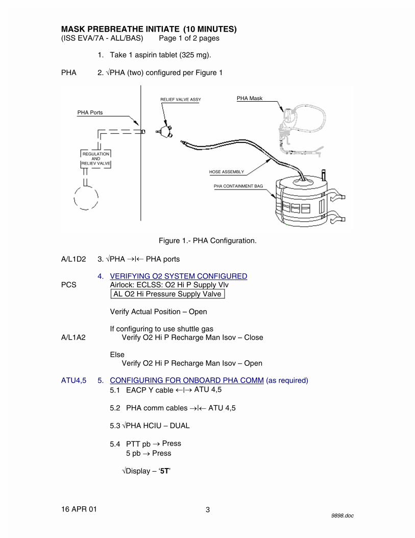
MASK PREBREATHE INITIATE (10 MINUTES) (ISS EVA/7A - ALL/BAS) Page 1 of 2 pages
16 APR 01 9898.doc
1. Take 1 aspirin tablet (325 mg). PHA 2. �PHA (two) configured per Figure 1
Figure 1.- PHA Configuration. A/L1D2 3. �PHA �|� PHA ports 4. VERIFYING O2 SYSTEM CONFIGURED PCS Airlock: ECLSS: O2 Hi P Supply Vlv
AL O2 Hi Pressure Supply Valve
Verify Actual Position – Open
If configuring to use shuttle gas A/L1A2 Verify O2 Hi P Recharge Man Isov – Close
Else Verify O2 Hi P Recharge Man Isov – Open ATU4,5 5. CONFIGURING FOR ONBOARD PHA COMM (as required) 5.1 EACP Y cable �|� ATU 4,5 5.2 PHA comm cables �|� ATU 4,5 5.3 �PHA HCIU – DUAL 5.4 PTT pb � Press
5 pb � Press
�Display – ‘5T’
PHA Ports
REGULATION AND
RELIEV VALVE
RELIEF VALVE ASSY PHA Mask
HOSE ASSEMBLY
PHA CONTAINMENT BAG
3

MASK PREBREATHE INITIATE (10 MINUTES) (ISS EVA/7A - ALL/BAS) Page 2 of 2 pages
16 APR 01 9898.doc
WARNING Positive mask O2 pressure and fit are necessary to ensure adequate prebreathe.
6. Don mask. PHA 7. Mask O2 control � EMERGENCY mask 8. Momentarily pull mask away from face.
�O2 flow 9. �Comm 10. Configure comm for PTT to alleviate noise, as required.
WARNING Do not terminate prebreathe until cabin pressure at 10.2 psia and 60-minute mask prebreathe completed.
11. Record mask P/B initiate time and continue mask prebreathe for
60 minutes.
GMT (MASK P/B INIT) _____/_____:_____ _____
4
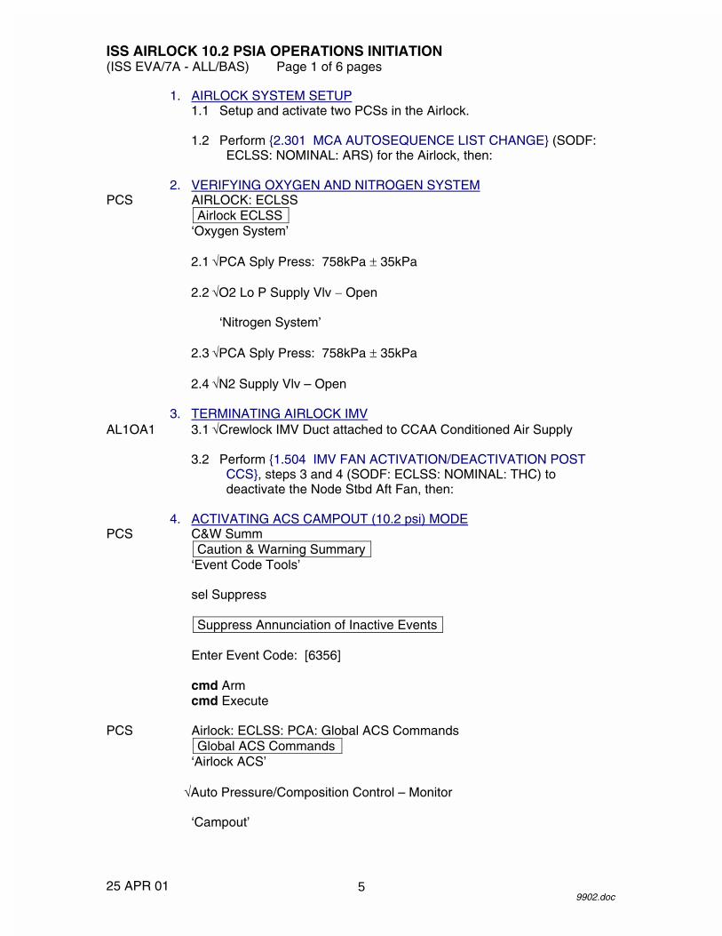
ISS AIRLOCK 10.2 PSIA OPERATIONS INITIATION (ISS EVA/7A - ALL/BAS) Page 1 of 6 pages
25 APR 01 9902.doc
1. AIRLOCK SYSTEM SETUP 1.1 Setup and activate two PCSs in the Airlock. 1.2 Perform {2.301 MCA AUTOSEQUENCE LIST CHANGE} (SODF:
ECLSS: NOMINAL: ARS) for the Airlock, then: 2. VERIFYING OXYGEN AND NITROGEN SYSTEM PCS AIRLOCK: ECLSS
Airlock ECLSS ‘Oxygen System’
2.1 �PCA Sply Press: 758kPa � 35kPa 2.2 �O2 Lo P Supply Vlv � Open
‘Nitrogen System’ 2.3 �PCA Sply Press: 758kPa � 35kPa 2.4 �N2 Supply Vlv – Open 3. TERMINATING AIRLOCK IMV AL1OA1 3.1 �Crewlock IMV Duct attached to CCAA Conditioned Air Supply 3.2 Perform {1.504 IMV FAN ACTIVATION/DEACTIVATION POST
CCS}, steps 3 and 4 (SODF: ECLSS: NOMINAL: THC) to deactivate the Node Stbd Aft Fan, then:
4. ACTIVATING ACS CAMPOUT (10.2 psi) MODE PCS C&W Summ
Caution & Warning Summary ‘Event Code Tools’
sel Suppress
Suppress Annunciation of Inactive Events
Enter Event Code: [6356]
cmd Arm cmd Execute
PCS Airlock: ECLSS: PCA: Global ACS Commands
Global ACS Commands ‘Airlock ACS’
�Auto Pressure/Composition Control – Monitor
‘Campout’
5
ISS AIRLOCK 10.2 PSIA OPERATIONS INITIATION (ISS EVA/7A - ALL/BAS) Page 2 of 6 pages
25 APR 01 9902.doc
4.1 cmd Initiate 4.2 �Primary PCA – LAB/Airlock (None/Airlock) 4.3 �Auto Pressure/Composition Control – Comp Control
AL ACS 4.4 �ACS Campout Status � Campout 5. CLOSING NODE 1 IMV VALVES PCS Node1: ECLSS: IMV Stbd Aft Valve
Node 1 IMV Stbd Aft Valve 5.1 �State � Enabled
‘Close’ 5.2 cmd Arm 5.3 cmd Close 5.4 Wait 15 seconds. 5.5 �Position – Closed PCS Node1: ECLSS: IMV Stbd Fwd Valve
Node 1 IMV Stbd Fwd Valve 5.6 �State � Enabled
‘Close’ 5.7 cmd Arm 5.8 cmd Close 5.9 Wait 15 seconds. 5.10 �Position � Closed 6. VERIFYING EMERGENCY EQUIPMENT IN AIRLOCK 6.1 Verify PFE located in PFE locker. 6.2 Verify three PHA masks located in Airlock. 6.3 Verify PBA masks located in Airlock for every isolated crewmember. 6.4 Verify CSA-CP located in Airlock.
6

ISS AIRLOCK 10.2 PSIA OPERATIONS INITIATION (ISS EVA/7A - ALL/BAS) Page 3 of 6 pages
25 APR 01 9902.doc
7. ACTIVATING AIRLOCK CABIN CIRCULATION AND CO2 REMOVAL CAUTION
When handling the Metox canister, take caution to protect the state indicator from being inadvertently switched to the E position.
7.1 Unstow new Metox canisters (two). 7.2 �Metox State Indicators – R 7.3 Remove caps from Metox canisters. 7.4 Stow caps in EMU Equipment Bag. A/L1A1 7.5 Rotate EDDA open. 7.6 Log new Metox canister location in IMS. 7.7 Open CO2 Removal Receptacle door. 7.8 �CO2 VALVE – REMOVAL 7.9 Install Metox canisters in CO2 Removal Receptacle per label on
closeout. 7.10 Close and latch CO2 Removal Receptacle door. 7.11 Rotate EDDA closed. 8. CLOSING NODE 1 STBD HATCH 8.1 Close Node 1 Stbd Hatch, actuate the hatch to the orange equalize
block position indicator on the window frame. 8.2 �Node 1 Stbd Hatch in orange position 9. DISABLING CAUTION AND WARNING ALARMS PCS C&W Summ
Caution & Warning Summary ‘Event Code Tools’
sel Suppress
Suppress Annunciation of Inactive Events
Enter Event Code: [6368]
cmd Arm cmd Execute
7

ISS AIRLOCK 10.2 PSIA OPERATIONS INITIATION (ISS EVA/7A - ALL/BAS) Page 4 of 6 pages
25 APR 01 9902.doc
Enter Event Code: [5910]
cmd Arm cmd Execute
Enter Event Code: [6576]
cmd Arm cmd Execute
10. INHIBITING AIRLOCK RAPID DEPRESS RESPONSE PCS Rapid Depress: Rapid Depress Response Software Control
US Rapid Depress Response Software Control ‘INT MDM Airlock Depress Response’
cmd Inhibit – Arm (�Inhibit Status – Armed) cmd Inhibit (�INT MDM Airlock Depress Response Status – Inhibit)
11. DEPRESSING TO 10.2 psi PCS AIRLOCK: ECLSS: PCA: O2 Intro
AL PCA O2 Intro Valve 11.1 cmd Open 11.2 �Position � Open PCS AIRLOCK: ECLSS: Depress Pump
AL Depress Pump 11.3 cmd RPC – Close 11.4 �RPC Position – Closed UIA 11.5 �DEPRESS PUMP ENABLE LED �
WARNING Do not initiate depress until 45 minutes of mask prebreathe is complete.
11.6 DEPRESS PUMP PWR sw � ON 11.7 Wait 10 seconds. C-Lk 11.8 DEPRESS PUMP MAN ISOV � OPEN PCS AIRLOCK: ECLSS
Airlock ECLSS ‘Equipment Lock’
8

ISS AIRLOCK 10.2 PSIA OPERATIONS INITIATION (ISS EVA/7A - ALL/BAS) Page 5 of 6 pages
25 APR 01 9902.doc
11.9 �Cab Press – decreasing 11.10 Continue depress to 647 mmHg (12.5 psia).
When Airlock at 12.5 psia 11.11 DEPRESS PUMP MAN ISOV � CLOSED 11.12 Wait 13 minutes. 11.13 DEPRESS PUMP MAN ISOV � OPEN 11.14 Continue depress to 517 mmHg (10.0 psia). C-Lk 11.15 Depress PUMP MAN ISOV � CLOSED 11.16 Verify ppO2 is between 2.40 psia and 3.06 psia. PCS AIRLOCK: ECLSS: PCA: O2 Intro
AL PCA O2 Intro Valve 11.17 cmd Close 11.18 �Position � Close UIA 11.19 DEPRESS PUMP PWR sw � OFF PCS AIRLOCK: ECLSS: Depress Pump
AL Depress Pump 11.20 cmd RPC – Open 11.21 �RPC Position – Open 12. ENABLING CAUTION AND WARNING ALARMS AND RESPONSE PCS C&W Summ
Caution & Warning Summary ‘Event Code Tools’
sel Suppress
Suppress Annunciation of Inactive Events
Enter Event Code: [6368]
cmd Arm cmd Execute
Enter Event Code: [5910]
cmd Arm cmd Execute
9

ISS AIRLOCK 10.2 PSIA OPERATIONS INITIATION (ISS EVA/7A - ALL/BAS) Page 6 of 6 pages
25 APR 01 9902.doc
Enter Event Code: [6576]
cmd Arm cmd Execute
Enter Event Code: [6356]
cmd Arm cmd Execute
PCS Rapid Depress: Rapid Depress Response Software Control
US Rapid Depress Response Software Control ‘INT MDM Airlock Depress Response’
cmd Enable (�INT MDM Airlock Depress Response Status – Enable)
10
MASK PREBREATHE TERMINATE (10 MINUTES) (ISS EVA/7A - ALL/BAS) Page 1 of 1 page
23 APR 01 9905.doc
WARNING Do not terminate prebreathe until airlock pressure at 10.2 psia and designated prebreathe time completed.
PHA 1. Mask O2 control � NORMAL mask
Record mask P/B terminate time.
GMT (MASK P/B TERM) _____/_____:_____ _____
2. Doff mask. A/L1D2 3. PHA �|� PHA port
Install cap on PHA port. PHA 4. Install cap on PHA. 5. Clean mask. 6. DECONFIGURING ONBOARD PHA COMM (as required) ATU4,5 HANG UP pb � Press
5 pb � Press
�Display – blank
PHA comm cable �|� ATU 4,5
EACP Y cable �|� ATU 4,5 7. Stow PHA mask in PHA bag.
11

26 APR 01
This Page Intentionally Blank
12

ISS AIRLOCK 10.2 PSIA OPERATIONS TERMINATION (ISS EVA/7A - ALL/BAS) Page 1 of 2 pages
11 APR 01 9909.doc
1. ENABLING CAUTION AND WARNING ALARMS PCS C&W Summ
Caution & Warning Summary ‘Event Code Tools’
sel Enable
Suppress Annunciation of Inactive Events
Enter Event Code: 6368 Event Message: E/L Cab P Low Warning � A/L
cmd Arm cmd Execute
Enter Event Code: 5910 Event Message: E/L Cab P Low Caution � A/L
cmd Arm cmd Execute
Enter Event Code: 6576 Event Message: Rapid Depress � A/L
cmd Arm cmd Execute
2. ACTIVATING EQUIPMENT POST 10.2 OPERATIONS 2.1 Perform {IMV VALVE RECONFIGURATION} (SODF: ECLSS:
NOMINAL: THC) to open the Node 1 Stbd Aft and Node 1 Stbd Fwd valves, then:
2.2 Perform {IMV FAN ACTIVATION} (SODF: ECLSS:NOMINAL:THC)
for the Node 1 Stbd Aft fan, then: 2.3 Perform {MCA AUTOSEQUENCE LIST CHANGE} (SODF: ECLSS:
NOMINAL: ARS) for Node/Lab/Airlock, then: 3. DEACTIVATING AIRLOCK CABIN CIRCULATION AND CO2 REMOVAL
NOTE When handling the Metox canister, take caution to protect the state indicator from being inadvertently switched to the E position.
A/L1A1 3.1 Rotate EDDA open. 3.2 Open CO2 Removal Receptacle door. 3.3 Remove Metox canisters from CO2 Removal Receptacle.
13

ISS AIRLOCK 10.2 PSIA OPERATIONS TERMINATION (ISS EVA/7A - ALL/BAS) Page 2 of 2 pages
11 APR 01 9909.doc
3.4 �Metox State Indicators � E 3.5 Unstow Metox canister caps from EMU Equipment Bag. 3.6 Install caps on Metox canisters. 3.7 Temporarily stow Metox canisters for future regeneration or use. 3.8 Close and latch CO2 Removal Receptacle door. 3.9 Rotate EDDA closed.
14

����������
���� �������
��
���
��
���
�
��
��
��
15

����������
�
������������������������������
��
���
��
���
�
��
��
��
16

AIRLOCK PREP FOR EVA OPS (30 MINUTES) (ISS EVA/7A - ALL/BAS) Page 1 of 2 pages
08 MAR 01 9911.doc
A/L 1. Remove non-EVA related bags/items stowed in Airlock. E-Lk 2. √SSC, PCS installed in E-Lk UIA 3. √PWR EV-1,2 sw (two) − OFF
√PWR EV-1,2 LEDs (four) − √WATER SUPPLY EV-1,2 vlv (two) − CLOSE √WATER REG EV-1,2 vlv (two) − SUPPLY √OXYGEN EMU1,2 vlv (two) − CLOSE √OXYGEN ORLAN vlv − CLOSE √OSCA − ���� (O2 CLOSED) √DEPRESS PUMP PWR sw − OFF √DEPRESS PUMP ENABLE LED −
C-Lk 4. √DEPRESS/REPRESS Cue Card installed in C-Lk 5. √EV Hatch MPEV − CLOSED 6. √DEPRESS PUMP MAN ISOV − CLOSED BCA 7. √MAIN POWER sw (four) − OFF
√MAIN POWER LEDs (four) − PSA 8. √MAIN POWER sw − OFF
√MAIN POWER LED − √SUIT SELECT sw (two) – OFF √SUIT SELECT LEDs (four) − √EMU MODE EMU1,2 sw (two) − PWR √IRU/UTILITY POWER sw − OFF
IRU 9. √POWER sw − OFF
√POWER LED − √PUMP sw − OFF √PUMP LED − √H2O OUTLET vlv (rotary) − CLOSED
Metox 10. √POWER sw − OFF Regen √ON LED −
√MODE sw − REGENERATE √FAULT OVERRIDE sw − OFF
DCM 11. √PWR − SCU
√FAN − OFF √O2 ACT − OFF √WATER − OFF √Water switch guard installed √COMM mode − HL √Comm FREQ − LOW √PURGE vlv − op (up) √Helmet purge vlv − cl, locked
17
AIRLOCK PREP FOR EVA OPS (30 MINUTES) (ISS EVA/7A - ALL/BAS) Page 2 of 2 pages
08 MAR 01 9911.doc
E-Lk 12. Unstow from floor Aisle Stowage Container: EMU Equipment Bag EMU Servicing Kit
Attach EMU Equipment Bag to A/L1A1. EMU1,2 13. √Helmet lights installed on EMUs
√EMU TVs installed on helmet lights 14. Waist ring ←|→ HUT 15. Remove LCVG.
Temporarily stow LCVG. 16. Waist ring →|← HUT 17. Temporarily stow MWS, BRT as required.
18

EMU SWAP (30 MINUTES) (ISS EVA/7A - ALL/BAS) Page 1 of 2 pages
08 FEB 01 9921.doc
NOTE EMU X is to be removed and EMU Y is to be installed.
1. Gloves �|� EMU X, if required UIA 2. �PWR EV-1(2) sw � OFF EMU X 3. SCU �|� DCM 4. Install DCM cover. C-Lk wall 5. Insert SCU in stowage pouch. 6. LCVG �|� Multiple Water Connector, if required 7. Helmet �|� HUT
Temporarily stow helmet. 8. Comm cap �|� electrical harness
Stow comm cap in LTA restraint bag. 9. Waist ring �|� HUT 10. Helmet �|� HUT 11. Release EMU from EDDA.
Temporarily stow EMU. EMU Y 12. Remove comm cap from LTA restraint bag.
Temporarily stow comm cap. 13. Release EMU from E-Lk ceiling. 14. Perform {LTA RESTRAINT STRAP REMOVAL} (SODF: ISS EVA:
AIRLOCK CONFIG), then: 15. Mount EMU on EDDA. 16. Waist ring �|� HUT
Remove stowed equipment from HUT/LTA, as required. 17. Waist ring � engage position
Waist ring �|� HUT 18. �Tether hook operation
19
EMU SWAP (30 MINUTES) (ISS EVA/7A - ALL/BAS) Page 2 of 2 pages
08 FEB 01 9921.doc
NOTE UIA Oxygen vlv for SCU connected to EMU Y must be closed prior to mating SCU.
If performing EMU CHECKOUT of EMU Y
UIA 19. OXYGEN EMU 1(2) vlv � CLOSE EMU X 20. Perform {LTA RESTRAINT STRAP INSTALLATION} (SODF: ISS
EVA: AIRLOCK CONFIG), then: 21. Install EMU on E-Lk ceiling.
20

LTA RESTRAINT STRAP REMOVAL (15 MINUTES) (ISS EVA/7A - ALL/BAS) Page 1 of 1 page
14 FEB 01 10073.doc
NOTE May be performed on EMU 1 and 2 simultaneously. Perform steps as required for current EMU configuration.
E-Lk 1. All LTA restraint attachments (six) �|� SAFER mount brackets (two) 2. Loosen cinch strap mechanism.
Strap SAFER mount brackets �|� SAFER striker plate on EMU PLSS 3. Remove LTA restraint strap from EMU PLSS.
Stow LTA restraint strap in LTA Restraint Bag Pouch leaving D-rings (three) connected to bag.
4. Engage EMU in EDDA. 5. Stow LTA Restraint Bag and LTA restraint strap.
21

26 APR 01
This Page Intentionally Blank
22

LTA RESTRAINT STRAP INSTALLATION (15 MINUTES) (ISS EVA/7A - ALL/BAS) Page 1 of 2 pages
14 FEB 01 10071.doc
NOTE May be performed on EMU 1 and 2 simultaneously. Perform steps as required for current EMU configuration.
E-Lk 1. Unstow LTA Restraint Bag and LTA restraint strap.
�LTA Restraint Bag attached to LTA restraint strap D-rings (three) 2. Remove EMU from EDDA. 3. LTA restraint strap SAFER mount brackets (two) �|� SAFER striker
plate on PLSS 4. Install elastic band of LTA restraint strap around SOP. 5. Tighten cinch strap mechanism. 6. LTA restraint strap French hooks (two) �|� SAFER mount brackets 7. Engage EMU in EDDA. 8. Stow LTA and suit arms inside LTA Restraint Bag. 9. Upper spring hooks (two) �|� SAFER mount brackets (two) such that
strap runs over shoulder 10. Lower spring hooks (two) �|� SAFER mount brackets (two) 11. Tighten all LTA restraint bag straps with bag as high as possible on EMU.
23

LTA RESTRAINT STRAP INSTALLATION (15 MINUTES) (ISS EVA/7A - ALL/BAS) Page 2 of 2 pages
14 FEB 01 10071.doc
24
EMU RESIZE (30 MINUTES)(EVA/7A - ALL/GEN) Page 1 of 2 pages
18 OCT 009916.doc
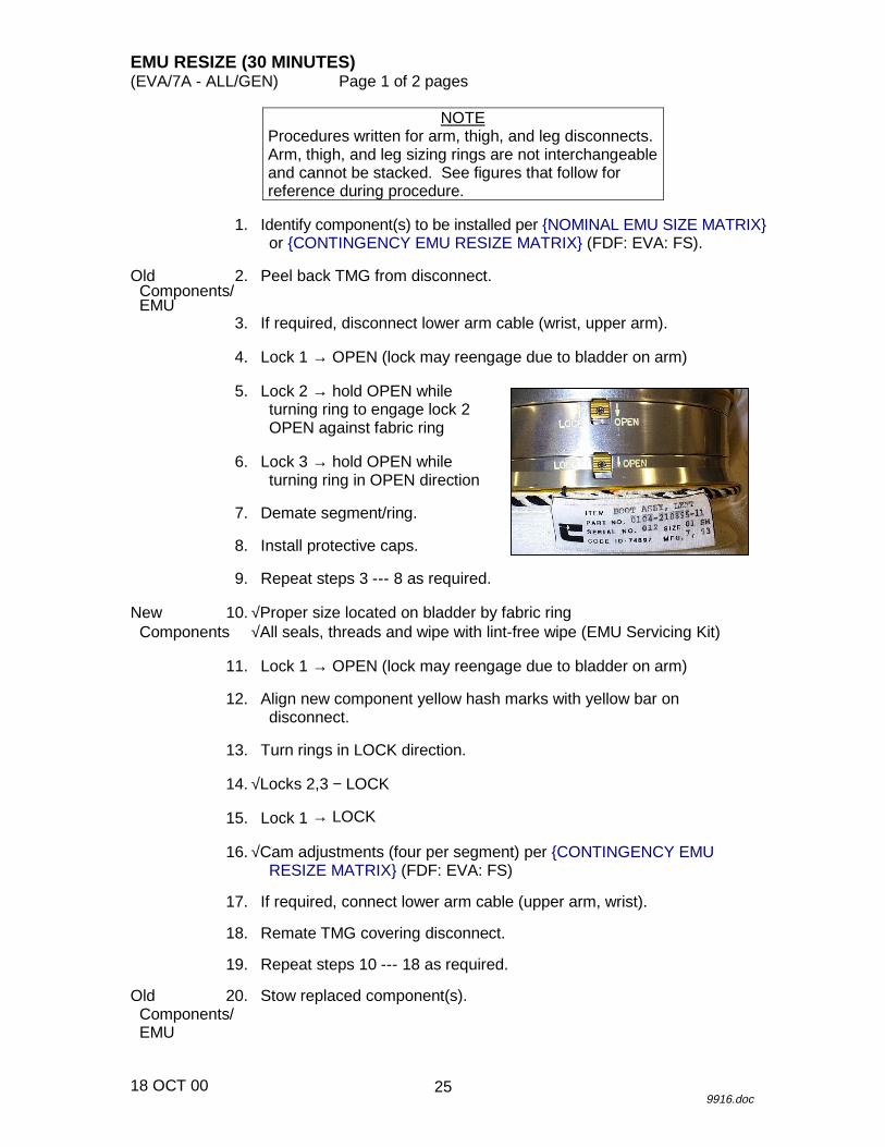
NOTEProcedures written for arm, thigh, and leg disconnects.Arm, thigh, and leg sizing rings are not interchangeableand cannot be stacked. See figures that follow forreference during procedure.
1. Identify component(s) to be installed per {NOMINAL EMU SIZE MATRIX}or {CONTINGENCY EMU RESIZE MATRIX} (FDF: EVA: FS).
Old 2. Peel back TMG from disconnect. Components/ EMU
3. If required, disconnect lower arm cable (wrist, upper arm).
4. Lock 1 → OPEN (lock may reengage due to bladder on arm)
5. Lock 2 → hold OPEN whileturning ring to engage lock 2OPEN against fabric ring
6. Lock 3 → hold OPEN whileturning ring in OPEN direction
7. Demate segment/ring.
8. Install protective caps.
9. Repeat steps 3 --- 8 as required.
New 10. √Proper size located on bladder by fabric ring Components √All seals, threads and wipe with lint-free wipe (EMU Servicing Kit)
11. Lock 1 → OPEN (lock may reengage due to bladder on arm)
12. Align new component yellow hash marks with yellow bar ondisconnect.
13. Turn rings in LOCK direction.
14. √Locks 2,3 − LOCK
15. Lock 1 → LOCK
16. √Cam adjustments (four per segment) per {CONTINGENCY EMURESIZE MATRIX} (FDF: EVA: FS)
17. If required, connect lower arm cable (upper arm, wrist).
18. Remate TMG covering disconnect.
19. Repeat steps 10 --- 18 as required.
Old 20. Stow replaced component(s). Components/ EMU
25

EMU RESIZE (30 MINUTES)(EVA/7A - ALL/GEN) Page 2 of 2 pages
18 OCT 009916.doc
26

EMU METOX INSTALLATION (10 MINUTES)(ISS EVA/7A - ALL/BAS) Page 1 of 1 page
01 FEB 019923.doc
NOTEWhen handling the Metox canister, take caution toprotect the state indicator from being inadvertentlyswitched to the E position.
1. Unstow new Metox canister.
√Metox state indicator − R
2. Rotate EDDA open.
3. Unzip thermal cover.Velcro thermal cover to top of EMU.
4. Remove Metox canister caps (two).Stow caps in EMU Equipment Bag.
5. Install Metox using label on canister for proper orientation.Latch canister in place.
6. Log new stowage location for Metox canister in IMS.
7. Close thermal cover zipper.
8. Rotate EDDA closed.
27

26 APR 01
This Page Intentionally Blank
28

EMU WATER RECHARGE BAG DUMP (20 MINUTES) (ISS EVA/7A - ALL/BAS) Page 1 of 2 pages
17 APR 01 9927.doc
NOTE SCU should be disconnected from the EMU when performing this procedure.
E-Lk 1. Unstow EMU Water Recharge Bag from floor bin.
Velcro bag to wall below IRU. IRU 2. EMU Water Recharge Bag hose →|←H2O IN port 3. √H2O outlet vlv (rotary) − CLOSED PCS 4. VERIFYING ISS WASTE WATER CONFIGURATION
LAB: ECLSS: H2O Vent LAB Water Vent
√Water Vent System Status – Inhibited
If Water Vent System Status – Enabled and Condensate Tank Quantity 1(2) ≥ 41.25 kg
Perform {USOS TO RS WATER TRANSFER} (SODF: ECLSS: NOMINAL: WRM).
UIA 5. WATER EV-1(2) SUPPLY vlv → OPEN 6. WATER EV-1(2) REG vlv → WASTE PSA 7. MAIN POWER sw → ON
√MAIN POWER LED − 8. IRU/UTILITY POWER sw → ON
√IRU/UTILITY POWER LED − √IRU volts: 27.0 --- 29.0
NOTE
The following step powers on the IRU. Verify the PRESS and TEMP LEDs briefly illuminate when IRU power is taken to ON.
IRU 9. POWER sw → ON
√POWER, PRESS, TEMP LEDs (three) − at startup
Wait until 2.5-second LED and pixel check complete, then 10. √POWER LED remains − 11. H2O outlet vlv (rotary) EMU SUPPLY
29

EMU WATER RECHARGE BAG DUMP (20 MINUTES) (ISS EVA/7A - ALL/BAS) Page 2 of 2 pages
17 APR 01 9927.doc
12. PUMP sw → ON
√PUMP LED − 13. √QUANTITY display − ↑
When dump is complete, then: IRU 14. PUMP sw → OFF
√PUMP LED − 15. H2O outlet vlv (rotary) CLOSED 16. Record value from QUANTITY display.
Record EMU Water Recharge Bag Serial Number (S/N). Report quantity and bag serial number to MCC-H as comm permits.
Date H2O Quantity Bag Serial Number
17. POWER sw → OFF
√POWER LED − PSA 18. IRU/UTILITY POWER sw → OFF
√IRU/UTILITY POWER LED − 19. MAIN POWER sw → OFF
√MAIN POWER LED − UIA 20. WATER EV-1(2) SUPPLY vlv → CLOSE 21. WATER EV-1(2) REG vlv → SUPPLY 22. EMU Water Recharge Bag ←|→ H2O IN port
Stow bag in floor bin, as required.
Log new stowage location for bag in IMS.
30

EMU WATER RECHARGE BAG FILL (40 MINUTES) (ISS EVA/7A - ALL/BAS) Page 1 of 1 page
12 APR 01 9926.doc
NOTE 1. To minimize contamination possibility, avoid touching
any internal parts of QDs or connections. 2. Each bag is limited to four in-flight uses.
E-Lk 1. Unstow EMU Water Recharge Bag (Payload Water Reservoir) from floor
bin, as required.
CAUTION Do not use water bags containing orange cards.
2. Transfer bag to orbiter galley.
CAUTION Do not fill EMU Water Recharge Bag for longer than 18 minutes.
3. EMU Water Recharge Bag �|� Orbiter Galley Aux Port 4. Set timer for 16 minutes.
Attach timer to Velcro square on EMU Water Recharge Bag.
When fill complete 5. EMU Water Recharge Bag �|� Orbiter Galley Aux Port 6. Transfer bag to ISS. 7. Record fill date for bag on white card.
Log fill date in IMS. E-Lk 8. Stow bag in floor bin.
31

26 APR 01
This Page Intentionally Blank
32
AIRLOCK DECONFIG POST EVA (30 MINUTES) (ISS EVA/7A - ALL/BAS) Page 1 of 2 pages
08 MAR 01 9930.doc
1. Stow LCVG in HUT (leave LCVG disconnected from Multiple Water Connector).
EMU1,2 2. Waist ring →|← HUT 3. √Helmet →|← HUT 4. MWS →|← HUT as required 5. BRT →|← HUT as required DCM 6. √PWR − SCU
√FAN − OFF √O2 ACT − OFF √WATER − OFF √Water switch guard installed √COMM mode − HL √Comm FREQ − LOW √PURGE vlv − op (up) √Helmet purge vlv − cl, locked
E-Lk 7. EMU Equipment Bag ←|→ panel A/L1A1
Stow EMU Equipment Bag in floor Aisle Stowage Container. 8. Stow EMU Servicing Kit in floor Aisle Stowage Container. EMU1,2 9. √Helmet lights installed on EMUs
√EMU TVs installed on helmet lights A/L1D2 10. √PHA ←|→ PHA port PHA 11. Clean mask. mask 12. Stow PHA mask, hose in PHA Bag. C-Lk 13. Strap PHA Bag to handrail directly above UIA. UIA 14. √PWR EV-1,2 sw (two) − OFF
√PWR EV-1,2 LEDs (four) − √WATER SUPPLY EV-1,2 vlv (two) − CLOSE √WATER REG EV-1,2 vlv (two) − SUPPLY √OXYGEN EMU1,2 vlv (two) − CLOSE √OXYGEN ORLAN vlv − CLOSE √OSCA − ���� (O2 CLOSED) √DEPRESS PUMP PWR sw − OFF √DEPRESS PUMP ENABLE LED −
33
AIRLOCK DECONFIG POST EVA (30 MINUTES) (ISS EVA/7A - ALL/BAS) Page 2 of 2 pages
08 MAR 01 9930.doc
C-Lk 15. √EV Hatch MPEV − CLOSED √DEPRESS PUMP MAN ISOV − CLOSED
BCA 16. √MAIN POWER sw (four) − OFF
√MAIN POWER LEDs (four) − PSA 17. √MAIN POWER sw − OFF
√MAIN POWER LED − √SUIT SELECT sw (two) − OFF √SUIT SELECT LEDs (four) − √EMU MODE EMU1,2 sw (two) − PWR √IRU/UTILITY POWER sw − OFF √IRU/UTILITY POWER LED −
IRU 18. √POWER sw − OFF
√POWER LED − √PUMP sw − OFF √PUMP LED − √H2O OUTLET vlv (rotary) − CLOSED
Metox 19. √POWER sw − OFF Regen √ON LED −
√MODE sw − REGENERATE √FAULT OVERRIDE sw − OFF
34
����������
�� ����
��
��
��
��
��
�
��
35

����������
�
�������������������������������
��
��
��
��
��
�
��
36

EMU CHECKOUT (ISS EVA/7A - ALL/BAS) Page 1 of 5 pages
24 FEB 01 9934.doc
NOTE 1. Procedures are written for simultaneous checkout of two EMUs. 2. ‘PWR RESTART’ message occurs and BITE light is illuminated
whenever EMU power is cycled. 3. Perform all DCM PWR switch throws with firm, deliberate action.
UIA 1. �OXYGEN EMU 1,2 vlv (two) � CLOSE
�PWR EV-1,2 sw (two) � OFF �PWR EV-1,2 LEDs (four) �
C-Lk wall 2. Remove SCUs from stowage straps and pouches.
Transfer SCU to E-Lk. DCM 3. Remove DCM Covers.
Velcro to DCM. 4. SCU �|� DCM
�SCU locked 5. Helmet �|� HUT 6. Comm cap �|� electrical harness 7. �LTA installed DCM 8. PWR � BATT
�STATUS: BATT VDC � 16.5 9. Perform {COMM CHECK}, all (SODF: ISS EVA: CHECKOUTS), then:
PRIMARY REGULATOR/FAN/PUMP CHECK (20 MINUTES/EMU) DCM 10. �STATUS: O2 P = 850 --- 950
EMU 1 2 3 10. O2 P
UIA 11. �EMU O2 SUPPLY PRESS gauge 850 --- 950 12. OXYGEN EMU 1,2 vlv (two) � OPEN 13. Install helmet, lock. 14. �Suit arms aligned
�Gloves locked �Helmet purge vlv � cl, locked
37

EMU CHECKOUT (ISS EVA/7A - ALL/BAS) Page 2 of 5 pages
24 FEB 01 9934.doc
DCM 15. PURGE vlv � cl (dn) 16. O2 ACT � IV, ‘O2 USE HIGH’ message, PRO 17. �STATUS: SUIT P: 0.4 --- 1.4 and stable (compare with gauge)
EMU 1 2 3 17. SUIT P (IV)
18. O2 ACT � PRESS, ‘O2 USE HIGH’ message, PRO
‘TIME LF’ message, PRO 19. �STATUS: SUIT P: 4.2 --- 4.4 and stable (compare with gauge)
�STATUS: H2O TEMP = ambient �STATUS: H2O GP/WP: 14.0 --- 16.0
EMU 1 2 3
19. SUIT P (PRESS)
H2O TEMP
H2O GP
H2O WP
20. O2 ACT � IV
Start timing manual leak check (2 minutes, SUIT �P � 0.3 psi).
EMU 1 2 3 20. SUIT �P
***************************************************************************
If �P � 0.3 psi, perform {FAILED LEAK CHECK (14.7/10.2 PSI)} (SODF: ISS EVA: EMU CONTINGENCY), then:
*************************************************************************** DCM 21. O2 ACT � OFF 22. PURGE vlv � op (up) 23. �STATUS: SUIT P < 0.4 (compare with gauge) 24. Gloves �|� EMU
Temporarily stow gloves in EMU Equipment Bag.
38
EMU CHECKOUT (ISS EVA/7A - ALL/BAS) Page 3 of 5 pages
24 FEB 01 9934.doc
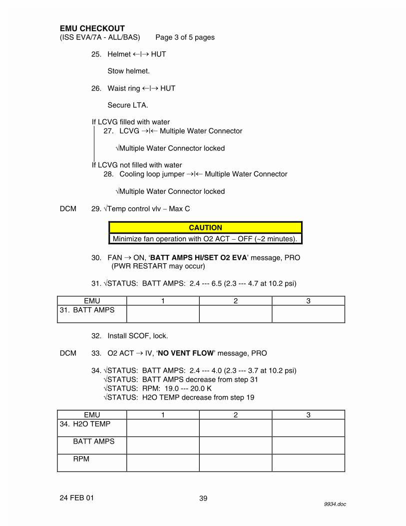
25. Helmet �|� HUT
Stow helmet. 26. Waist ring �|� HUT
Secure LTA.
If LCVG filled with water 27. LCVG �|� Multiple Water Connector
�Multiple Water Connector locked
If LCVG not filled with water 28. Cooling loop jumper �|� Multiple Water Connector
�Multiple Water Connector locked DCM 29. �Temp control vlv � Max C
CAUTION
Minimize fan operation with O2 ACT � OFF (~2 minutes). 30. FAN � ON, ‘BATT AMPS HI/SET O2 EVA’ message, PRO
(PWR RESTART may occur) 31. �STATUS: BATT AMPS: 2.4 --- 6.5 (2.3 --- 4.7 at 10.2 psi)
EMU 1 2 3 31. BATT AMPS
32. Install SCOF, lock. DCM 33. O2 ACT � IV, ‘NO VENT FLOW’ message, PRO 34. �STATUS: BATT AMPS: 2.4 --- 4.0 (2.3 --- 3.7 at 10.2 psi)
�STATUS: BATT AMPS decrease from step 31 �STATUS: RPM: 19.0 --- 20.0 K �STATUS: H2O TEMP decrease from step 19
EMU 1 2 3
34. H2O TEMP
BATT AMPS
RPM
39

EMU CHECKOUT (ISS EVA/7A - ALL/BAS) Page 4 of 5 pages
24 FEB 01 9934.doc
35. �Fan noise steady PSA 36. �EMU MODE EMU1,2 sw (two) � PWR 37. MAIN POWER sw � ON
�MAIN POWER LED � 38. SUIT SELECT sw (two) � EMU 1,2
�EMU1,2 Volts: 18.0 --- 19.0 UIA 39. PWR EV-1,2 sw (two) � ON
�PWR EV-1,2 EMU LEDs (two) � DCM 40. PWR � SCU UIA 41. �PWR EV-1,2 Amps: 1.5 --- 4.8 (1.5 --- 4.5 at 10.2 psi)
EMU 1 2 3 41. PWR EV-1,2
AMPS
DCM 42. O2 ACT � OFF, ‘O2 IS OFF’ message, PRO 43. FAN � OFF 44. PWR � BATT PSA 45. SUIT SELECT sw (two) � OFF
�SUIT SELECT LEDs (four) �
SOP CHECK (2 MINUTES/EMU) DCM 46. �STATUS: SOP P: 5800 --- 6800
Cycle to SUIT P.
EMU 1 2 3 46. SOP P
47. �SOP gauge 5800 --- 6800
Note SOP interstage gauge.
40

EMU CHECKOUT (ISS EVA/7A - ALL/BAS) Page 5 of 5 pages
24 FEB 01 9934.doc
EMU 1 2 3 47. SOP GAUGE
INT GAUGE
48. While depressing SOP manual override (50 seconds maximum)
�SOP interstage gauge < 600 DCM �STATUS: SUIT P: 3.4 --- 3.9 and stable
EMU 1 2 3 48. SUIT P
INT GAUGE
49. Remove SCOF.
Stow SCOF in EMU Equipment Bag. DCM 50. COMM mode � HL 51. LCVG (cooling loop jumper) �|� Multiple Water Connector
Stow LCVG in HUT. 52. Install helmet, LTA. DCM 53. PWR � SCU
BATTERY CHARGE CHECK INIT (10 MINUTES) PSA 54. EMU MODE EMU 1,2 sw (two) � CHRG BC3,4 55. Verify CH1 VOLTs > 0 56. Contact MCC-H to perform {EVA COMM DECONFIG}, all (SODF: ISS
EVA: CHECKOUTS).
41

26 APR 01
This Page Intentionally Blank
42

COMM CHECK (30 MINUTES) (ISS EVA/7A - ALL/BAS) Page 1 of 8 pages
14 FEB 01 9935.doc
CHECKING HARDLINE ATU 4,5 1. √EACP Y cable →|← EACP
√EACP Y cable →|← ATUs √No calls configured (display − blank)
EACP 2. PWR sw → ON
√EMU1,2 mode sel (two) − DUAL IV ATU 6 3. Connect headset.
PTT pb → Press 5 pb → Press
√Display − ‘5T’
ATU 4,5 4. PTT pb → Press
5 pb → Press
√Display − ‘5T’ EV1,2 5. Don comm caps. DCM 6. √COMM mode − HL 7. Perform IV/EV comm check. IV ATU 4, 8. HANG UP pb → Press 5,6 5 pb → Press EACP 9. PWR sw → OFF
CHECKING ALTERNATE RADIOS/414.2 MHZ NOTE
Steps 10 --- 16 may be performed by MCC-H.
CAUTION Only one UHF string should be powered on at a time to avoid hardware damage.
IV PCS 10. VERIFYING UHF 1 IS POWERED OFF MCC-H C&T: UHF
UHF Overview
Verify RPCM LAD52B A RPC 08 − Open
43

COMM CHECK (30 MINUTES) (ISS EVA/7A - ALL/BAS) Page 2 of 8 pages
14 FEB 01 9935.doc
11. POWERING ON UHF 2 C&T: UHF: RPCM LA1B H RPC 04 RPCM LA1B H RPC 04
√Close Cmd − Enabled
‘RPC Position’
cmd Close (Verify − Cl)
12. ENABLING UHF 2 CYCLIC I/O
C&T: UHF: UHF 2 Command UHF 2 Command
‘Cyclic I/O and Bus FDIR’
sel CB CT-2 RT Status
CB CT-2 RT Status ‘RT Address and Name: 23 UHF-2’
cmd Enable Execute (Verify RT Status − Ena)
13. VERIFYING UHF 2 BUS FDIR INHIBIT
C&T: UHF UHF Overview
‘UHF 2 Command’
Verify Bus FDIR − Inhibit 14. VERIFYING UHF 2 FAIL RECOVERY INHIBIT
C&T: UHF UHF Overview
‘UHF 2 Command’
Verify Fail Recovery − Inhibited 15. VERIFYING UHF 2 CONFIGURATION
C&T: UHF UHF Overview
‘Configuration’
Verify Xmit Power − Low Verify Frequency: 414.2
44
COMM CHECK (30 MINUTES) (ISS EVA/7A - ALL/BAS) Page 3 of 8 pages
14 FEB 01 9935.doc
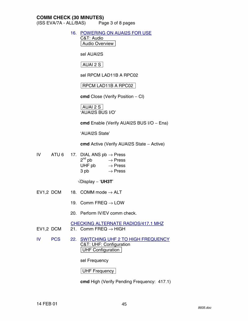
16. POWERING ON AUAI2S FOR USE C&T: Audio Audio Overview
sel AUAI2S
AUAI 2 S
sel RPCM LAD11B A RPC02
RPCM LAD11B A RPC02
cmd Close (Verify Position − Cl)
AUAI 2 S
‘AUAI2S BUS I/O’
cmd Enable (Verify AUAI2S BUS I/O − Ena)
‘AUAI2S State’
cmd Active (Verify AUAI2S State − Active) IV ATU 6 17. DIAL ANS pb → Press
2nd pb → Press UHF pb → Press 3 pb → Press
√Display − ‘UH3T’
EV1,2 DCM 18. COMM mode → ALT 19. Comm FREQ → LOW 20. Perform IV/EV comm check.
CHECKING ALTERNATE RADIOS/417.1 MHZ EV1,2 DCM 21. Comm FREQ → HIGH IV PCS 22. SWITCHING UHF 2 TO HIGH FREQUENCY
C&T: UHF: Configuration UHF Configuration
sel Frequency
UHF Frequency
cmd High (Verify Pending Frequency: 417.1)
45

COMM CHECK (30 MINUTES) (ISS EVA/7A - ALL/BAS) Page 4 of 8 pages
14 FEB 01 9935.doc
UHF Configuration
sel Set Actual Configuration
UHF Set Actual Configuration
cmd Send Command
UHF Configuration ‘Actual’
Verify Frequency: 417.1
EV1,2 23. Perform IV/EV comm check. IV ATU 6 24. HANG UP pb → Press
2nd pb → Press UHF pb → Press 3 pb → Press
CHECKING PRIMARY RADIOS/417.1 MHZ
EV1,2 DCM 25. COMM mode → PRI
NOTE Steps 26 --- 33 may be performed by MCC-H.
IV PCS 26. DISABLING UHF 2 CYCLIC I/O MCC-H C&T: UHF: UHF 2 Command
UHF 2 Command ‘Cyclic I/O and Bus FDIR’
sel CB CT-2 RT Status
CB CT-2 RT Status
‘RT Address and Name: 23 UHF-2’
cmd Inhibit Execute (Verify RT Status − Inh) 27. POWERING OFF UHF 2
C&T: UHF: RPCM LA1B H RPC 04 RPCM LA1B H RPC 04
‘RPC Position’
cmd Open (Verify RPC Position − Op)
CAUTION UHF 2 must be powered off prior to powering on UHF 1 to avoid hardware damage.
46
COMM CHECK (30 MINUTES) (ISS EVA/7A - ALL/BAS) Page 5 of 8 pages
14 FEB 01 9935.doc
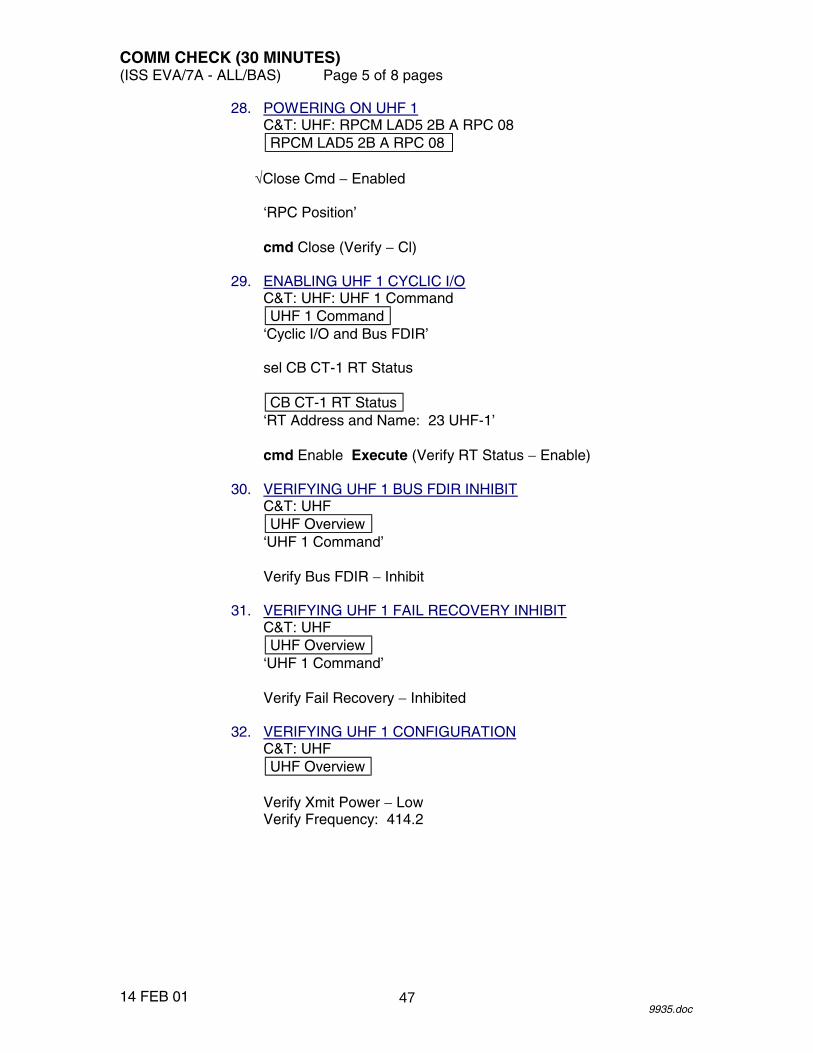
28. POWERING ON UHF 1 C&T: UHF: RPCM LAD5 2B A RPC 08 RPCM LAD5 2B A RPC 08
√Close Cmd − Enabled
‘RPC Position’
cmd Close (Verify − Cl)
29. ENABLING UHF 1 CYCLIC I/O
C&T: UHF: UHF 1 Command UHF 1 Command
‘Cyclic I/O and Bus FDIR’
sel CB CT-1 RT Status
CB CT-1 RT Status ‘RT Address and Name: 23 UHF-1’
cmd Enable Execute (Verify RT Status − Enable)
30. VERIFYING UHF 1 BUS FDIR INHIBIT
C&T: UHF UHF Overview
‘UHF 1 Command’
Verify Bus FDIR − Inhibit 31. VERIFYING UHF 1 FAIL RECOVERY INHIBIT
C&T: UHF UHF Overview
‘UHF 1 Command’
Verify Fail Recovery − Inhibited 32. VERIFYING UHF 1 CONFIGURATION
C&T: UHF UHF Overview
Verify Xmit Power − Low Verify Frequency: 414.2
47
COMM CHECK (30 MINUTES) (ISS EVA/7A - ALL/BAS) Page 6 of 8 pages
14 FEB 01 9935.doc
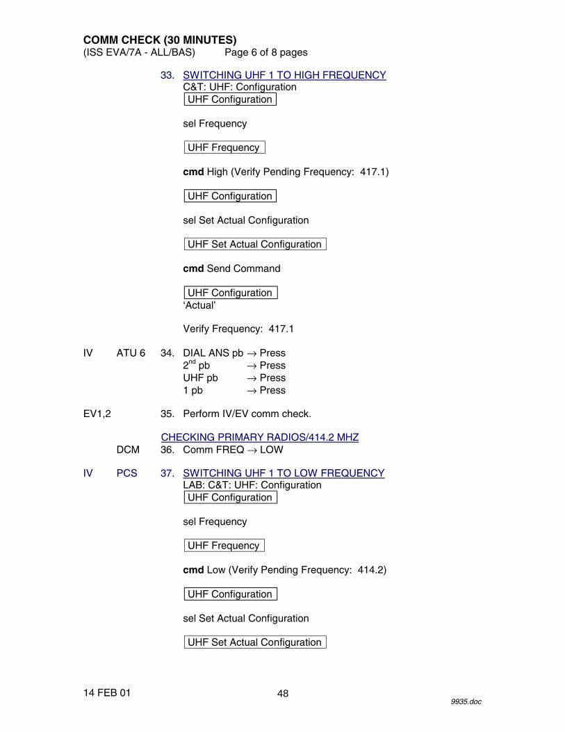
33. SWITCHING UHF 1 TO HIGH FREQUENCY C&T: UHF: Configuration UHF Configuration
sel Frequency
UHF Frequency
cmd High (Verify Pending Frequency: 417.1)
UHF Configuration
sel Set Actual Configuration
UHF Set Actual Configuration
cmd Send Command
UHF Configuration
‘Actual’
Verify Frequency: 417.1 IV ATU 6 34. DIAL ANS pb → Press
2nd pb → Press UHF pb → Press 1 pb → Press
EV1,2 35. Perform IV/EV comm check.
CHECKING PRIMARY RADIOS/414.2 MHZ DCM 36. Comm FREQ → LOW IV PCS 37. SWITCHING UHF 1 TO LOW FREQUENCY
LAB: C&T: UHF: Configuration UHF Configuration
sel Frequency
UHF Frequency
cmd Low (Verify Pending Frequency: 414.2)
UHF Configuration
sel Set Actual Configuration
UHF Set Actual Configuration
48

COMM CHECK (30 MINUTES) (ISS EVA/7A - ALL/BAS) Page 7 of 8 pages
14 FEB 01 9935.doc
cmd Send Command
UHF Configuration ‘Actual’
Verify Frequency: 414.2
EV1,2 38. Perform IV/EV comm check. IV ATU 6 39. HANG UP pb → Press
2nd pb → Press UHF pb → Press 1 pb → Press
CHECKING AIR-TO-GROUND COMMUNICATION
IV PCS 40. CONFIGURING EVA PUBLIC CALL C&T: Audio Audio Overview
sel IAC(X) Call Select where X = powered and active IAC 21
IAC(X) Call Select
‘Public1’
sel Call Setup
Public 1 Call Select
cmd UHF 1
IAC(X) Call Select ‘Public1’
√GND 2 − ‘TL’ √UHF 1 − ‘TL’
ATU 6 41. PTT pb → Press
1 pb → Press
√Display − ‘1TG’ EV1,2 42. √RF comm with MCC-H 43. Doff comm caps.
49

COMM CHECK (30 MINUTES) (ISS EVA/7A - ALL/BAS) Page 8 of 8 pages
14 FEB 01 9935.doc
IV PCS 44. DECONFIGURING EVA PUBLIC CALL C&T: Audio Audio Overview
sel IAC(X) Call Select where X = powered and active IAC 21
IAC(X) Call Select
‘Public1’
sel Hangup
Public 1 Call Hangup
cmd UHF 1
IAC(X) Call Select ‘Public1’
√UHF 1 not present
45. POWERING OFF AUAI2S
C&T: Audio Audio Overview
sel AUAI2S
AUAI2 S
sel RPCM LAD11B A RPC 02
RPCM LAD11B A RPC 02
‘RPC Position’
cmd Open (Verify PRC Position − Op)
AUAI 2S ‘AUAI2S BUS I/O’
cmd Inhibit (Verify AUAI2S Bus I/O − Inh)
‘AUAI2S State’
cmd Standby (Verify AUAI2S State − Standby)
50

EVA COMM DECONFIG (5 MINUTES)(ISS EVA/7A - ALL/BAS) Page 1 of 2 pages
24 JAN 019936.doc
IV PCS 1. DISABLING UHF 1 CYCLIC I/OMCC-H C&T: UHF: UHF 1 Command
UHF 1 Command‘Cyclic I/O and Bus FDIR’
sel CB CT-1 RT Status
CB CT-1 RT Status‘RT Address and Name: 23 UHF 1’
cmd Inhibit Execute (Verify RT Status − Inh)
2. POWERING OFF UHF 1C&T: UHF: RPCM LAD52B A RPC 08RPCM LAD52B A RPC 08
‘RPC Position’
cmd Open (Verify RPC Position − Op)
3. POWERING OFF AUAI2SC&T: AudioAudio Overview
sel AUAI2S
AUAI2 S
sel RPCM LAD11B A RPC 02
RPCM LAD11B A RPC 02‘RPC Position’
cmd Open (Verify RPC Position − Op)
AUAI 2S‘AUAI2S BUS I/O’
cmd Inhibit (Verify AUAI2S Bus I/O − Inh)
‘AUAI2S State’
cmd Standby (Verify AUAI2S State − Standby)
4. DECONFIGURING EVA PUBLIC CALLC&T: AudioAudio Overview
sel IAC(X) Call Select where X = powered and active IAC 21
51

EVA COMM DECONFIG (5 MINUTES)(ISS EVA/7A - ALL/BAS) Page 2 of 2 pages
24 JAN 019936.doc
IAC(X) Call Select‘Public1’
sel Hangup
Public 1 Call Hangup
cmd UHF 1cmd UHF 3
IAC(X) Call Select‘Public1’
√UHF 1 not present√UHF 3 not present
52

REBA POWERED HARDWARE CHECKOUT (15 MINUTES) (ISS EVA/7A - ALL/BAS) Page 1 of 2 pages
11 APR 01 9937.doc
NOTE Procedure written for simultaneous checkout of 12-volt hardware on multiple EMUs.
EMUs 1. �REBA installed on PLSS
�REBA sw � OFF
If EMU TV capability 2. Install EMU TV on helmet lights; note camera addresses.
Refer to Figure 1. 3. Record camera addresses for each EMU.
Camera Addresses EMU 1 EMU 2 EMU 3
4. Unstow EMU TV power cable. 5. EMU TV power cable �|� ground plug 6. EMU TV power cable �|� EMU TV
If no EMU TV capability 7. �EMU TV power cable �|� ground plug 8. �Upper arm connection mated 9. �Glove heater sw (one per glove) � OFF 10. Lower arm pwr harness �|� gloves
NOTE To avoid excessive battery consumption and heat buildup, deactivate heaters once heat detected at finger tips.
11. REBA sw (1 per EMU) � ON, pull tab toward right arm of suit 12. Glove heater sw (two per EMU) � ON
When heat detected on all outside fingertips 13. Glove heater sw (two per EMU) � OFF
If EMU TV capability 14. EMU TV power pb � Press
�Green LED �
53

REBA POWERED HARDWARE CHECKOUT (15 MINUTES) (ISS EVA/7A - ALL/BAS) Page 2 of 2 pages
11 APR 01 9937.doc
15. EMU TV power pb � Press
�Green LED � 16. REBA sw (1 per EMU) � OFF, pull tab toward left arm of suit 17. Lower arm pwr harness �|� gloves 18. Stow lower arm and glove pwr harness connectors under TMG.
Figure 1.- REBA Connection for ERCA.
54

EMU TO AIRLOCK INTERFACE CHECK (30 MINUTES) (ISS EVA/7A - ALL/BAS) Page 1 of 5 pages
28 MAR 01 9938.doc
NOTE 1. Procedures are written for simultaneous powerup of two EMUs. 2. ‘PWR RESTART’ message occurs and BITE light is illuminated
whenever EMU power is cycled. 3. Perform all DCM PWR switch throws with firm, deliberate action.
EMU POWER VERIFICATION
UIA 1. �PWR EV-1,2 sw (two) � OFF �PWR EV-1,2 LEDs (four) � �EMU O2 SUPPLY PRESS gauge: 850 --- 950
C-Lk wall 2. Remove SCUs from stowage straps and pouches.
Transfer SCU to E-Lk. DCM 3. Remove DCM Covers.
Velcro to DCM 4. SCU �|� DCM
�SCU locked 5. Helmet �|� HUT
Temporarily stow helmet. 6. �Comm cap �|� electrical harness DCM 7. PWR � BATT
CAUTION EMU must be on BATT power when UIA suit power is turned on.
PSA 8. �EMU MODE EMU1,2 sw (two) � PWR 9. MAIN POWER sw � ON
�MAIN POWER LED � 10. SUIT SELECT sw (two) � EMU 1,2
�EMU 1,2 LEDs (two) � �EMU 1,2 Volts: 18.0 --- 19.0
UIA 11. PWR EV-1,2 sw (two) � ON
�PWR EV-1,2 EMU LEDs (two) � DCM 12. PWR � SCU
55

EMU TO AIRLOCK INTERFACE CHECK (30 MINUTES) (ISS EVA/7A - ALL/BAS) Page 2 of 5 pages
28 MAR 01 9938.doc
13. �STATUS: H2O TEMP = ambient
EMU 1 2 3 13. H2O TEMP
14. Waist ring �|� HUT
Secure LTA. 15. Unstow the following from EMU Equipment Bag:
Cooling loop jumper SCOF
16. Cooling loop jumper �|� Multiple Water Connector DCM 17. Temp control vlv � MAX C
CAUTION
Minimize fan operation with O2 ACT � OFF (~2 minutes). 18. FAN � ON UIA 19. �PWR EV-1,2 AMPS: 1.5 --- 6.5 (1.5 --- 4.7 at 10.2 psi)
EMU 1 2 3 19. PWR EV-1,2
AMPS
20. Install SCOF, lock. DCM 21. O2 ACT � IV, ‘NO VENT FLOW’ message, PRO 22. �STATUS: H2O TEMP decrease from step 13
�STATUS: RPM: 19.0 --- 20.0 K
EMU 1 2 3 22. H2O TEMP
RPM
UIA 23. �PWR EV-1,2 AMPS: 1.5 --- 4.0 (1.5 --- 3.6 at 10.2 psi)
�PWR EV-1,2 AMPS decrease from step 19
56

EMU TO AIRLOCK INTERFACE CHECK (30 MINUTES) (ISS EVA/7A - ALL/BAS) Page 3 of 5 pages
28 MAR 01 9938.doc
EMU 1 2 3 23. PWR EV-1,2
AMPS
RF COMM CHECK
NOTE Steps 24 --- 28 may be completed by MCC-H.
IV PCS 24. POWERING ON UHF 1 MCC-H C&T: UHF: RPCM LAD5 2B A RPC 08
RPCM LAD5 2B A RPC 08
�Close Cmd � Enabled
‘RPC Position’
cmd Close (Verify � Cl) 25. ENABLING UHF 1 CYCLIC I/O
C&T: UHF: UHF 1 Command UHF 1 Command
‘Cyclic I/O and Bus FDIR’
sel CB CT-1 RT Status
CB CT-1 RT Status ‘RT Address and Name: 23 UHF-1’
cmd Enable Execute (Verify RT Status � Enable)
26. VERIFYING UHF 1 BUS FDIR INHIBIT
C&T: UHF UHF Overview
‘UHF 1 Command’
Verify Bus FDIR � Inhibit 27. VERIFYING UHF 1 FAIL RECOVERY INHIBIT
C&T: UHF UHF Overview
‘UHF 1 Command’
Verify Fail Recovery � Inhibited 28. VERIFYING UHF 1 CONFIGURATION
C&T: UHF UHF Overview
‘Configuration’
57

EMU TO AIRLOCK INTERFACE CHECK (30 MINUTES) (ISS EVA/7A - ALL/BAS) Page 4 of 5 pages
28 MAR 01 9938.doc
Verify Xmit Power � Low Verify Frequency: 414.2
EV 29. Don comm cap. DCM 30. COMM mode � PRI 31. �Comm FREQ � LOW IV ATU 6 32. DIAL ANS pb � Press
2nd pb � Press UHF pb � Press 1 pb � Press
EV1,2 33. Perform IV/EV comm check. IV ATU 6 34. HANG UP pb � Press EV1,2 35. Doff comm caps. DCM 36. COMM mode � HL IV PCS 37. DISABLING UHF 1 CYCLIC I/O MCC-H C&T: UHF: UHF 1 Command
UHF 1 Command ‘Cyclic I/O and Bus FDIR’
sel CB CT-1 RT Status
CB CT-1 RT Status
‘RT Address and Name: 23 UHF 1’
cmd Inhibit Execute (Verify RT Status � Inh) 38. POWERING OFF UHF 1
C&T: UHF: RPCM LAD52B A RPC 08 RPCM LAD52B A RPC 08
‘RPC Position’
cmd Open (Verify RPC Position � Op)
EMU RECONFIGURATION DCM 39. O2 ACT � OFF 40. FAN � OFF, ‘O2 IS OFF’ message, PRO 41. Remove SCOF.
Stow SCOF in EMU Equipment Bag.
58

EMU TO AIRLOCK INTERFACE CHECK (30 MINUTES) (ISS EVA/7A - ALL/BAS) Page 5 of 5 pages
28 MAR 01 9938.doc
UIA 42. PWR EV-1,2 sw (two) � OFF
�PWR EV-1,2 LEDs (four) � PSA 43. SUIT SELECT sw (two) � OFF
�SUIT SELECT LEDs (four) � 44. MAIN POWER sw � OFF
�MAIN POWER LED � 45. Cooling loop jumper �|� Multiple Water Connector
Stow cooling loop jumper in EMU Equipment Bag. 46. Comm cap �|� electrical harness, if required
Stow comm cap. 47. Install helmet, LTA. DCM 48. SCU �|� DCM 49. Install DCM cover. C-Lk 50. Insert SCU in stowage pouch. wall
59

26 APR 01
This Page Intentionally Blank
60

SAFER CHECKOUT (30 MINUTES) (ISS EVA/7A - ALL/BAS) Page 1 of 3 pages
11 APR 01 9939.doc
NOTE Procedures written for simultaneous checkout of two SAFERs.
BOTH 1. Remove SAFER and SAFER CHECKOUT RESULTS Cue Card
from Stowage Bag. 2. �Inhibitor installed and locked 3. Remove Stowage Strap from thruster towers.
Unfold thruster towers. 4. Inspect:
Thruster tower hinges Tower latches
�TMG not blocking thrusters
5. Fold thruster towers. 6. Install Stowage Strap. PM 7. MAN ISOL vlv � OP (dn) 8. Deploy HCM.
�Proper deployment
CAUTION Minimize time with SAFER powered (~1 minute).
NOTE
1. Have SAFER CHECKOUT RESULTS Cue Card with proper serial number ready to record status.
2. If display is nonresponsive during self-test, press
DISP sw to view failure message; record message; then, press DISP sw again to resume test.
9. As required, review SELF-TEST SEQUENCE. 10. Perform Self-Test
Start timer. HCM PWR sw � TST/ON
Wait until GN2 XX% PWR XX% displayed.
�AAH LED �
61

SAFER CHECKOUT (30 MINUTES) (ISS EVA/7A - ALL/BAS) Page 2 of 3 pages
11 APR 01 9939.doc
PWR sw � ON PWR sw � TST/ON
Follow displayed instructions on HCM � SELF TEST � WAIT displayed
If able, count thruster clicks (twenty-four).
**********************************************************
If NSI CIRCUIT OPEN or ‘FAIL: … ’ message displayed
Note failure message.
Press DISP sw to resume test.
If HC TO DETENT message displayed Note message.
�HC grip springs to center position
**********************************************************
When RATE CHECK displayed, rotate SAFER at least � 3 deg/sec sequentially in each rotational axis.
11. � GO FOR EVA or FAILED TEST displayed 12. PWR sw � ON 13. DISP: Record GN2 %, PWR %, BATT V on SAFER CHECKOUT
RESULTS Cue Card. 14. PWR sw � OFF 15. Stop timer, record ‘ON Time’ (~1 minute desired). 16. �GN2 % � 87
�PWR % � 45 �BATT V � 35
17. Report status and SAFER serial number to MCC-H. HCM 18. MODE sw � ROT 19. Stow HCM. PM 20. MAN ISOL vlv � CL (up) 21. Stow SAFER and Cue Card in Stowage Bag. 22. �Inhibitor installed
62

SAFER CHECKOUT (30 MINUTES) (ISS EVA/7A - ALL/BAS) Page 3 of 3 pages
11 APR 01 9939.doc
SELF-TEST SEQUENCE (for reference only; do not perform) HCM 1. NSI circuit test. 2. SELF TEST � WAIT
�Twenty-four thruster clicks �THR LED
3. DEPRESS AAH 4. MODE � ROT (if in TRAN)
MODE – TRAN 5. HC grip detent test. 6. HC +X (fwd), (-X, +Y (rt), -Y, +Z (dn), -Z, +P (twist up), -P) 7. RATE CHECK
Rotate SAFER at least � 3 deg/sec sequentially in each rotational axis.
63

26 APR 01
This Page Intentionally Blank
64

SAFER CHECKOUT RESULTS(ISS EVA/7A - ALL/BAS) Page 1 of 1 page
01 FEB 019940.doc
SAFER SERIAL NUMBER _______________
GMT ON Time GN2 % PWR % BATT V GMT ON Time GN2 % PWR % BATT V1 272 283 294 305 316 327 338 349 3510 3611 3712 3813 3914 4015 4116 4217 4318 4419 4520 4621 4722 4823 4924 5025 5126 52
BATTERY CHANGEOUT
GMT OLD BATT SN NEW BATT SNNOTE
SAFER battery expected to last for52 1-minute checkouts and have atleast 45 % pwr remaining.
65

26 APR 01
This Page Intentionally Blank
66

PGT CHECKOUT (ISS EVA/7A - ALL/BAS) Page 1 of 1 page
14 FEB 01 9941.doc
C/L 1. Unstow PGT from Crewlock IV bag. PGT 2. �PWR � OFF
�Battery connector covering removed 3. Install battery. 4. Ratchet collar� not MTR 5. Cycle MTL settings.
Cycle bayonet fittings. 6. Speed collar� CAL 7. PWR� ON 8. �Display � ‘TRIG TO CAL’ 9. Press, release trigger to calibrate. 10. �Display � ‘CAL PASSED’ 11. Ratchet collar� MTR 12. �All LEDs �
�Display � ‘LED TEST’ 13. Press trigger and hold.
�BAT VDC � 36.0 14. Speed collar� CW 15. Press trigger and verify drive rotates . 16. Speed collar� CCW 17. Press trigger and verify drive rotates . 18. To verify programmed settings, cycle MODE/torque collar/speed
collar and compare with {PGT STANDARD SETTINGS} (SODF: ISS EVA: CHECKOUTS) or {PGT SETTINGS TABLE} (SODF: ISS EVA).
19. PWR� OFF
67

26 APR 01
This Page Intentionally Blank
68

PGT STANDARD SETTINGS (ISS EVA/7A - ALL/BAS) Page 1 of 1 page
23 APR 01 9942.doc
SETTINGS
TORQUE SETPOINT
(FT-LB)
TORQUE WINDOW (FT-LB)
TORQUE THRESHOLD
(FT-LB)
TURNS
A1 2.5 � 1.0 1.0 -- A2 3.8 � 1.0 1.0 -- A3 4.8 � 1.0 1.0 -- A4 6.3 � 1.0 1.0 -- A5 7.0 � 1.0 1.0 -- A6 8.3 � 1.0 1.0 -- A7 9.2 � 1.0 1.0 -- B1 12.0 � 1.0 1.0 -- B2 16.0 � 1.2 1.0 -- B3 18.4 � 1.7 1.0 -- B4 19.4 � 1.9 1.0 -- B5 22.0 � 2.0 1.0 -- B6 24.0 � 2.0 1.0 -- B7 25.5 � 2.0 1.0 --
SETTINGS CCW1 CCW2 CCW3 CW3 CW2 CW1
SPEED (RPM) 10 30 60 60 30 10
SLEEP TIME 15 min AUTO – OFF TIME 30 min
MULTI-SETTING TORQUE LIMITER
(MTL) SETTINGS 2.5 5.5
10.5 15.5 23.5 30.5
69

26 APR 01
This Page Intentionally Blank
70

����������
������
��
��
��
���
��
��
71

����������
�
�� ������������� ��������������
��
��
��
���
��
��
72
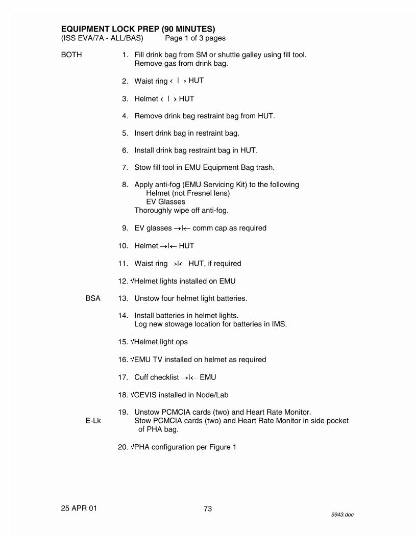
EQUIPMENT LOCK PREP (90 MINUTES) (ISS EVA/7A - ALL/BAS) Page 1 of 3 pages
25 APR 01 9943.doc
BOTH 1. Fill drink bag from SM or shuttle galley using fill tool. Remove gas from drink bag.
2. Waist ring �|� HUT 3. Helmet �|� HUT 4. Remove drink bag restraint bag from HUT. 5. Insert drink bag in restraint bag. 6. Install drink bag restraint bag in HUT. 7. Stow fill tool in EMU Equipment Bag trash. 8. Apply anti-fog (EMU Servicing Kit) to the following
Helmet (not Fresnel lens) EV Glasses
Thoroughly wipe off anti-fog. 9. EV glasses �|� comm cap as required 10. Helmet �|� HUT 11. Waist ring �|� HUT, if required 12. �Helmet lights installed on EMU BSA 13. Unstow four helmet light batteries. 14. Install batteries in helmet lights.
Log new stowage location for batteries in IMS. 15. �Helmet light ops 16. �EMU TV installed on helmet as required 17. Cuff checklist �|� EMU 18. �CEVIS installed in Node/Lab 19. Unstow PCMCIA cards (two) and Heart Rate Monitor. E-Lk Stow PCMCIA cards (two) and Heart Rate Monitor in side pocket
of PHA bag. 20. �PHA configuration per Figure 1
73

EQUIPMENT LOCK PREP (90 MINUTES) (ISS EVA/7A - ALL/BAS) Page 2 of 3 pages
25 APR 01 9943.doc
Figure 1.- PHA Configuration. 21. Visually inspect PHA, PHA mask for any damage.
Perform the following as required EV1 LAB/ 22. Perform {CYCLE ERGOMETER VIBRATION ISOLATION NOD1 AND STABILIZATION: CEVIS - ON LINE MODE
OPERATIONS}, step 3, (SODF: MED OPS: NOMINAL: CMS), then:
BOTH A/L1D2 23. PHA �|� PHA port 24. Unstow PHA mask from PHA bag. PHA 25. Don mask. mask 26. Mask O2 control � EMERGENCY 27. Momentarily pull mask away from face.
�O2 flow EV2 28. Mask O2 control � NORMAL 29. Doff mask.
Leave EV2 PHA in E-Lk. EV1 30. While on mask, deploy length of hose required to access
CEVIS. LAB/ 31. Perform portion of exercise protocol on CEVIS to verify NOD1 sufficient flow. 32. Mask O2 control � NORMAL
PHA Ports
REGULATION AND
RELIEV VALVE
RELIEF VALVE ASSY PHA Mask
HOSE ASSEMBLY
PHA CONTAINMENT BAG
74

EQUIPMENT LOCK PREP (90 MINUTES) (ISS EVA/7A - ALL/BAS) Page 3 of 3 pages
25 APR 01 9943.doc
33. Doff mask. LAB/ 34. Perform {CYCLE ERGOMETER VIBRATION ISOLATION NOD1 AND STABILIZATION: CEVIS - ON LINE MODE
OPERATIONS}, step 6.1, (SODF: MED OPS: NOMINAL: CMS), then:
35. Stage PHA bag in LAB/NOD1. BOTH A/L1D2 36. PHA �|� PHA port
Install cap on PHA port. PHA 37. Depress mask O2 control to bleed down line. mask
Install cap on PHA. EV1 38. Coil deployed hose.
Insert coiled hose in side pocket of PHA bag. BOTH 39. Stow PHA mask in PHA bag.
VERIFYING EMERGENCY EQUIPMENT IN AIRLOCK 40. Verify PFE located in PFE locker. 41. Verify three PHA masks located in airlock. 42. Verify three PBAs located in airlock. 43. Verify CSA-CP located in airlock.
CONFIGURING IMV DUCT 44. Unstow C-Lk IMV Duct. 45. Attach C-Lk IMV Duct to CCAA Conditioned Air on hose coupling
panel.
75

26 APR 01
This Page Intentionally Blank
76

EVA PREP (170 MINUTES) (ISS EVA/7A - ALL/BAS) Page 1 of 8 pages
24 APR 01 9944.doc
EXERCISE PREBREATHE/PREP FOR DONNING (110 MINUTES) IV EV1 EV2 1. Perform {ISS
AIRLOCK10.2 PSI OPERATIONS INITIATION}, steps 1 --- 5 (SODF: ISS EVA: 10.2 PSI OPS).
2. Route PHA hose to CEVIS (secure bag to handrail). Tether hose for strain relief.
4. Perform {CYCLE
ERGOMETER VIBRATION ISOLATION AND STABILIZATION: CEVIS – ON LINE MODE OPERATIONS}, step 3 (SODF: MED OPS: NOMINAL: CMS).
3. Verify bungees are configured.
5. Position Heart Rate
Monitor on CEVIS. Install EV1 PCMCIA card in CEVIS.
6. Perform {ISS
AIRLOCK10.2 PSI OPERATIONS INITIATION}, steps 6 --- 7 (SODF: ISS EVA: 10.2 PSI OPS).
EV1,2 7. Don Ergometer shoes.
Don other over-the-head garments. Don TCU top.
8. Take one aspirin tablet (325 mg).
Prebreathe Verification Table Event EV1 (GMT) EV2 (GMT) Mask P/B Init Exercise Term Airlock Depress Init Airlock Depress to 10.2 psi Term
Mask P/B Term The following criteria that must be met to satisfy protocol
1) Do not depress airlock until the following criteria are met a) A minimum of 50 minutes of mask prebreathe for both
crewmembers is complete. b) A mimimum of 15 minutes has elapsed since exercise terminate for the last crewmember.
2) Do not terminate mask prebreathe until the following criteria are met
a) Airlock is at 10.2 psi. b) A minimum of 45 minutes has elapsed after exercise
terminate for the last crewmember. c) A minimum of 80 minutes of mask prebreathe is
complete.
77

EVA PREP (170 MINUTES) (ISS EVA/7A - ALL/BAS) Page 2 of 8 pages
24 APR 01 9944.doc
WARNING Positive mask O2 pressure and fit are necessary to ensure adequate prebreathe.
INITIATING MASK PREBREATHE
EV1,2 A/L1D2 9. PHA �|� PHA port 10. Don mask. PHA 11. Mask O2 control � EMERGENCY mask 12. Momentarily pull mask away from face.
�O2 flow 13. �Comm, as required 14. Configure comm for PTT to alleviate noise, as required.
WARNING
Do not terminate prebreathe until airlock pressure at 10.2 psia and 80 minutes prebreathe (45 minutes post exercise) for both crewmembers completed.
15. Record mask P/B initiate time and continue mask prebreathe at
least 80 minutes.
GMT (MASK P/B INIT) _____/_____:_____ _____
NOTE
1. Maintain > 60 rpm and match arm/leg cadence (pedaling effort at < 60 rpm becomes noticeably more difficult). Use table values for workload and modify arm/leg cadence to maintain heart rate within range given. If heart rate > 90 % of maximum, decrease workload by 25 watt increments until < 90 %.
2. If an interruption of either exercise or mask
prebreathe of up to 2 minutes occurs during the 10-minute exercise, extend the 75 % Max VO2 portion of the table for a duration equal to the interruption.
78
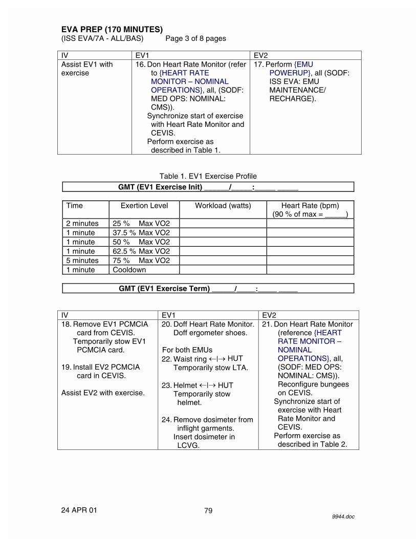
EVA PREP (170 MINUTES) (ISS EVA/7A - ALL/BAS) Page 3 of 8 pages
24 APR 01 9944.doc
IV EV1 EV2 Assist EV1 with exercise
16. Don Heart Rate Monitor (refer to {HEART RATE MONITOR – NOMINAL OPERATIONS}, all, (SODF: MED OPS: NOMINAL: CMS)).
Synchronize start of exercise with Heart Rate Monitor and CEVIS.
Perform exercise as described in Table 1.
17. Perform {EMU POWERUP}, all (SODF: ISS EVA: EMU MAINTENANCE/ RECHARGE).
Table 1. EV1 Exercise Profile
GMT (EV1 Exercise Init) ______/_____:_____ _____
Time Exertion Level Workload (watts) Heart Rate (bpm) (90 % of max = _____)
2 minutes 25 % Max VO2 1 minute 37.5 % Max VO2 1 minute 50 % Max VO2 1 minute 62.5 % Max VO2 5 minutes 75 % Max VO2 1 minute Cooldown
GMT (EV1 Exercise Term) ______/_____:_____ _____
IV EV1 EV2 18. Remove EV1 PCMCIA
card from CEVIS. Temporarily stow EV1 PCMCIA card.
19. Install EV2 PCMCIA
card in CEVIS. Assist EV2 with exercise.
20. Doff Heart Rate Monitor. Doff ergometer shoes.
For both EMUs 22. Waist ring �|� HUT
Temporarily stow LTA. 23. Helmet �|� HUT
Temporarily stow helmet.
24. Remove dosimeter from
inflight garments. Insert dosimeter in LCVG.
21. Don Heart Rate Monitor (reference {HEART RATE MONITOR – NOMINAL OPERATIONS}, all, (SODF: MED OPS: NOMINAL: CMS)). Reconfigure bungees on CEVIS.
Synchronize start of exercise with Heart Rate Monitor and CEVIS.
Perform exercise as described in Table 2.
79

EVA PREP (170 MINUTES) (ISS EVA/7A - ALL/BAS) Page 4 of 8 pages
24 APR 01 9944.doc
Table 2. EV2 Exercise Profile
GMT (EV2 Exercise Init) ______/_____:_____ _____
Time Exertion Level Workload (watts) Heart Rate (bpm) (90 % of max = _____)
2 minutes 25 % Max VO2 1 minute 37.5 % Max VO2 1 minute 50 % Max VO2 1 minute 62.5 % Max VO2 5 minutes 75 % Max VO2 1 minute Cooldown
GMT (EV2 Exercise Term) ______/_____:_____ _____
IV EV1/MCC-H EV2 25. Remove EV2 PCMCIA
card from CEVIS. Temporarily stow EV2 PCMCIA card.
26. Perform {EVA COMM CONFIG}, all (SODF: ISS EVA: EVA PREP).
27. Doff Heart Rate Monitor. Doff ergometer shoes.
EV1,2 E-Lk 28. Don MAG, TCU bottom, LCVG, biomed.
When 50 minutes of mask prebreathe complete, perform {ISS AIRLOCK 10.2 PSI OPERATIONS INITIATION}, steps 8 --- 11 (SODF: ISS EVA: 10.2 PSI OPS), then:
DCM 29. �STATUS: SOP P: 5800 --- 6800 (compare with gauge) 30. �Waist ring � op 31. Don LTA (attach donning handles as required).
80
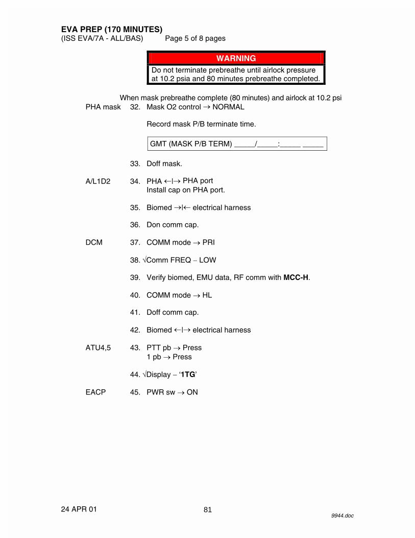
EVA PREP (170 MINUTES) (ISS EVA/7A - ALL/BAS) Page 5 of 8 pages
24 APR 01 9944.doc
WARNING Do not terminate prebreathe until airlock pressure at 10.2 psia and 80 minutes prebreathe completed.
When mask prebreathe complete (80 minutes) and airlock at 10.2 psi
PHA mask 32. Mask O2 control � NORMAL
Record mask P/B terminate time.
GMT (MASK P/B TERM) _____/_____:_____ _____
33. Doff mask. A/L1D2 34. PHA �|� PHA port
Install cap on PHA port. 35. Biomed �|� electrical harness 36. Don comm cap. DCM 37. COMM mode � PRI 38. �Comm FREQ � LOW 39. Verify biomed, EMU data, RF comm with MCC-H. 40. COMM mode � HL 41. Doff comm cap. 42. Biomed �|� electrical harness ATU4,5 43. PTT pb � Press
1 pb � Press 44. �Display � ‘1TG’ EACP 45. PWR sw � ON
81

EVA PREP (170 MINUTES) (ISS EVA/7A - ALL/BAS) Page 6 of 8 pages
24 APR 01 9944.doc
EMU DONNING (55 MINUTES) NOTE
May be performed by EV1 and EV2 simultaneously. 46. Take one aspirin tablet (325 mg), if not taken previously. 47. �Suit arms aligned 48. �Wrist disconnects � op 49. Stow IV glasses as required. 50. Don thumb loops. 51. �Biomed connector is outside of HUT 52. Don HUT. 53. Release thumb loops. 54. �Suit arms aligned 55. Don EV glasses as required.
Don comm cap. 56. �Comm 57. Biomed �|� electrical harness 58. LCVG �|� Multiple Water Connector
�Multiple Water Connector locked 59. �Thermal cover clear of waist ring 60. Waist ring � engage position 61. Waist ring �|� HUT
�Waist ring locked 62. Remove donning handles.
Stow donning handles in EMU Equipment Bag. 63. Cover waist ring. 64. �Electrical harness clear of neck ring 65. �Drink vlv position
82
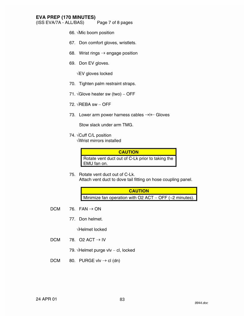
EVA PREP (170 MINUTES) (ISS EVA/7A - ALL/BAS) Page 7 of 8 pages
24 APR 01 9944.doc
66. �Mic boom position 67. Don comfort gloves, wristlets. 68. Wrist rings � engage position 69. Don EV gloves.
�EV gloves locked 70. Tighten palm restraint straps. 71. �Glove heater sw (two) � OFF 72. �REBA sw � OFF 73. Lower arm power harness cables �|� Gloves
Stow slack under arm TMG. 74. �Cuff C/L position
�Wrist mirrors installed
CAUTION Rotate vent duct out of C-Lk prior to taking the EMU fan on.
75. Rotate vent duct out of C-Lk.
Attach vent duct to dove tail fitting on hose coupling panel.
CAUTION
Minimize fan operation with O2 ACT � OFF (~2 minutes). DCM 76. FAN � ON 77. Don helmet.
�Helmet locked DCM 78. O2 ACT � IV 79. �Helmet purge vlv � cl, locked DCM 80. PURGE vlv � cl (dn)
83

EVA PREP (170 MINUTES) (ISS EVA/7A - ALL/BAS) Page 8 of 8 pages
24 APR 01 9944.doc
If EMU TV capability 81. Unstow EMU TV power cable. 82. EMU TV power cable �|� Ground plug 83. EMU TV power cable �|� EMU TV EV2 84. Repeat steps 46 --- 83 if donning performed serially.
EMU CHECK (5 MINUTES) BOTH 85. �Cooling
****************************************************************** If cooling insufficient, IV depress and hold pump priming valve on back of EMU (30 seconds maximum).
****************************************************************** 86. Temp control vlv � as required 87. �Wrist rings � covered
�Waist rings � covered �WATER � OFF �PWR � SCU �FAN � ON �Comm FREQ � LOW �Helmet purge vlv � cl, locked �PURGE vlv � cl (dn)
NOTE
During LEAK CHECK procedure, when ‘SET O2 IV’ message displayed, wait 30 seconds and �SUIT P gauge stable (4.2 --- 4.4) before moving O2 ACT � IV.
88. STATUS: LEAK CHECK?, PRO
Follow displayed instructions.
********************************************************************** If LEAKAGE HI SUIT P X.X go to {FAILED LEAK CHECK (14.7/10.2 PSI)} (SODF: ISS EVA: EMU CONTINGENCY).
********************************************************************** 89. Go to {EMU PURGE} (SODF: ISS EVA: EVA PREP).
84

EMU PURGE (ISS EVA/7A - ALL/BAS) Page 1 of 1 page
16 APR 01 9945.doc
NOTE Flex arms and legs periodically and avoid overcooling during purge/prebreathe.
BOTH DCM 1. O2 ACT � PRESS 2. PURGE vlv � op (up), begin 15-minute purge clock
Record purge start time.
GMT (PURGE START) _____/_____:_____ _____
WARNING To ensure sufficiently low PPN2 levels in the EMU, do not repress Equipment Lock until 5 minutes of purge is complete.
When 5 minutes of purge complete
IV 3. Node 1 Stbd Hatch MPEV � Open 4. MCC-H report equalization time. 5. Open Node 1 Stbd Hatch per decal.
When 15-minute purge complete BOTH DCM 6. PURGE vlv � cl (dn) 7. O2 ACT � IV 8. Go to {EMU PREBREATHE} (SODF: ISS EVA: EVA PREP).
85

26 APR 01
This Page Intentionally Blank
86

EMU PREBREATHE (ISS EVA/7A - ALL/BAS) Page 1 of 3 pages
23 APR 01 9946.doc
GMT (PREBREATHE START) _____/_____:_____ _____
1. Begin prebreathe clock. 2. �MWS installed as required PHA 3. Depress mask O2 control to mask bleed down line.
Install cap on PHA. 4. Stow PHA mask in PHA Bag. 5. Egress EDDA.
Stow EDDA handles.
SAFER DONNING (30 MINUTES) IV 6. Remove SAFER from Stowage Bag.
Remove Stowage Straps from thruster towers. Stow Stowage Straps in EMU Equipment Bag. Unfold thruster towers.
7. Inspect:
Thruster tower hinges Tower latches
�TMG not blocking thrusters
8. �TMG clear from SAFER striker plate on EMU PLSS PM 9. Remove Inhibitor.
Close, fasten port cover. 10. MAN ISOL vlv � OP (dn) 11. Latch � PRELOAD 12. Latch to recess butterfly in housing.
CAUTION Latch past softstop can bind latch.
13. Latch to softstop. 14. Latch � ENGAGE 15. PLSS �|� thruster towers 16. Push latch in and (~90�).
Protocol Prebreathe Duration Exercise 01:00 Campout 00:40 14.7 psi 04:00
87

EMU PREBREATHE (ISS EVA/7A - ALL/BAS) Page 2 of 3 pages
23 APR 01 9946.doc
****************************** If latch will not engage
Latch � PRELOAD Latch . Return to step 13.
****************************** 17. Latch � PRELOAD 18. Latch until ratcheting.
CAUTION Latch may disengage SAFER.
19. Continue ratcheting until lock marking on latch and tower aligned. 20. Latch � LOCK 21. �Access to HCM deploy lever
�TMG not blocking thruster 22. Repeat steps 6 --- 21 for SAFER 2.
PREPARING FOR DEPRESS (10 MINUTES) IV 23. Remove loose equipment from C-Lk.
�EVA tools installed in C-Lk 24. REBA sw � ON, pull tab toward right arm of suit
If EMU TV capability 25. EMU TV power pb � Press
�Green LED � EV 26. Ingress C-Lk. C-Lk 27. �DEPRESS PUMP MAN ISOV � CLOSED IV DCM 28. Remove water switch guard (two).
Stow water switch guard in EMU Equipment Bag. IV 29. Egress C-Lk.
CAUTION Verify EV crew is clear of hatch mechanism.
30. IV Hatch � CLOSE, lock
88

EMU PREBREATHE (ISS EVA/7A - ALL/BAS) Page 3 of 3 pages
23 APR 01 9946.doc
31. �IV Hatch equalization valve � OFF 32. �EMERGENCY MPEV � CLOSED
If O2 system configured for shuttle gas, then: 33. CONFIGURE O2 SYSTEM FOR STATION GAS A/L1A2 33.1 O2 Xovr Vlv (VL011) � CLOSE 33.2 O2 Hi P Rechrg Man Isov (VL010) � OPEN
When prebreathe time complete EV UIA 34. �DEPRESS PUMP PWR sw � OFF
�DEPRESS PUMP ENABLE LED �
On MCC-H GO, go to {CREWLOCK DEPRESS} (Cue Card) (SODF: ISS EVA: DEPRESS/REPRESS).
89

26 APR 01
This Page Intentionally Blank
90

EVA COMM CONFIG (5 MINUTES)(ISS EVA/7A - ALL/BAS) Page 1 of 3 pages
24 JAN 019947.doc
CAUTIONOnly 1 UHF string should be powered onat a time to avoid hardware damage.
IV PCS 1. VERIFYING UHF 2 IS POWERED OFFMCC-H C&T: UHF
UHF Overview
Verify RPCM LA1B H RPC 04 − Open
2. POWERING ON UHF 1C&T: UHF: RPCM LAD5 2B A RPC 08RPCM LAD5 2B A RPC 08
√Close Cmd − Enabled
‘RPC Position’
cmd Close (Verify − Cl)
3. ENABLING UHF 1 CYCLIC I/OC&T: UHF: UHF 1 CommandUHF 1 Command
‘Cyclic I/O and Bus FDIR’
sel CB CT-1 RT Status
CB CT-1 RT Status‘RT Address and Name: 23 UHF 1’
cmd Enable Execute (Verify RT Status − Enable)
4. VERIFYING UHF 1 BUS FDIR INHIBITC&T: UHFUHF Overview
‘UHF 1 Command’
Verify Bus FDIR − Inhibit
5. VERIFYING UHF 1 FAIL RECOVERY INHIBITC&T: UHFUHF Overview
‘UHF 1 Command’
Verify Fail Recovery − Inhibited
91

EVA COMM CONFIG (5 MINUTES)(ISS EVA/7A - ALL/BAS) Page 2 of 3 pages
24 JAN 019947.doc
6. VERIFYING UHF 1 CONFIGURATIONC&T: UHFUHF Overview
‘Configuration’
Verify Xmit Power − LowVerify Frequency − 414.2
7. CONFIGURING EVA PUBLIC CALLC&T: AudioAudio Overview
sel IAC(X) Call Select where X = powered and active IAC 21
IAC(X) Call Select‘Public1’
sel Call Setup
Public 1 Call Select
cmd UHF 1cmd UHF 3
IAC(X) Call Select‘Public1’
√GND 2 − ‘TL’√UHF 1 − ‘TL’√UHF 3 − ‘TL’
8. POWERING ON AUAI2S FOR REDUNDANCYC&T: AudioAudio Overview
sel AUAI2S
AUAI2 S
sel RPCM LAD11B A RPC02
RPCM LAD11B A RPC02
cmd Close (Verify Position − Cl)
AUAI2 S‘AUAI2S BUS I/O’
cmd Enable (Verify AUAI2 S Bus I/O − Ena)
92

EVA COMM CONFIG (5 MINUTES)(ISS EVA/7A - ALL/BAS) Page 3 of 3 pages
24 JAN 019947.doc
‘AUAI2S State’
cmd Active (Verify AUAI2S State − Active)
93

26 APR 01
This Page Intentionally Blank
94

����������
��� � ���
��
��
��
���
��
��
��
95

����������
�
������������������������������
��
��
��
���
��
��
��
96
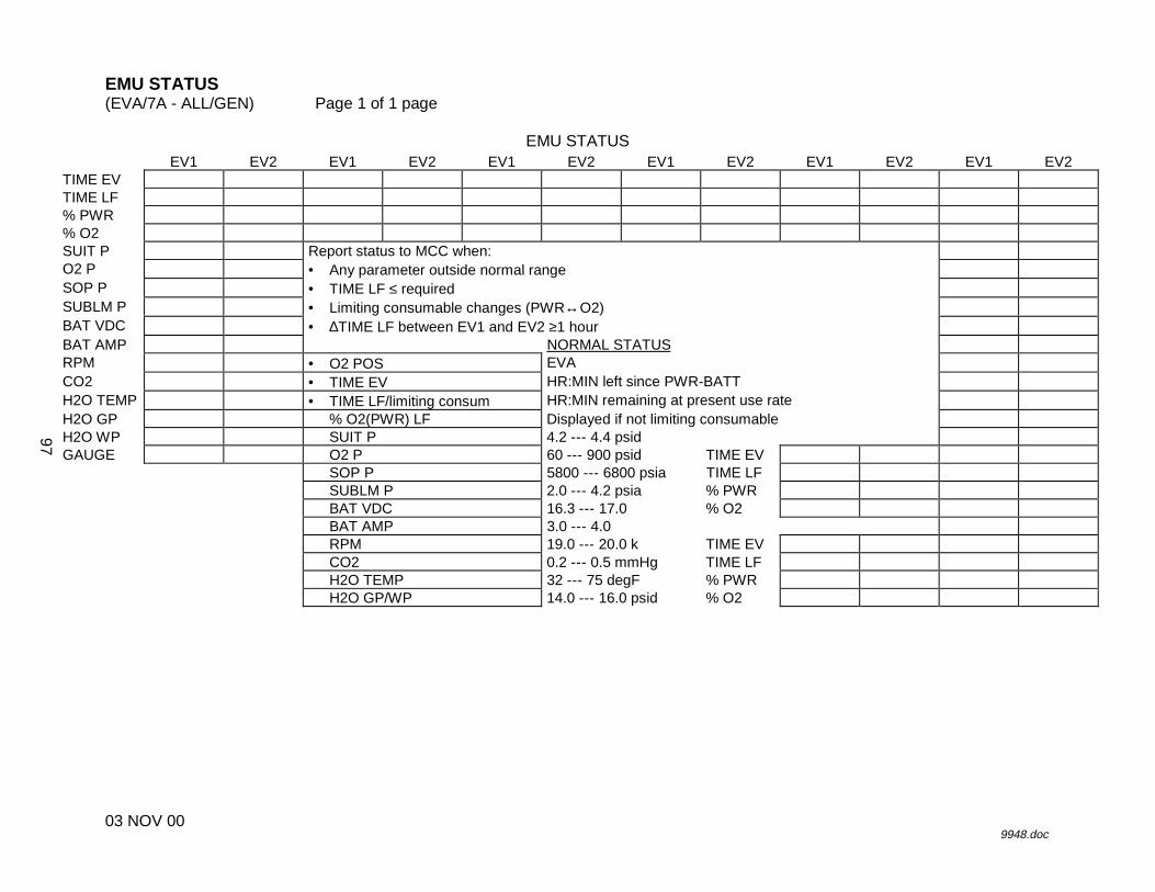
EMU STATUS(EVA/7A - ALL/GEN) Page 1 of 1 page
03 NOV 009948.doc
EMU STATUSEV1 EV2 EV1 EV2 EV1 EV2 EV1 EV2 EV1 EV2 EV1 EV2
TIME EVTIME LF% PWR% O2SUIT P Report status to MCC when:O2 P • Any parameter outside normal rangeSOP P • TIME LF ≤ requiredSUBLM P • Limiting consumable changes (PWR↔O2)BAT VDC • ∆TIME LF between EV1 and EV2 ≥1 hourBAT AMP NORMAL STATUSRPM • O2 POS EVACO2 • TIME EV HR:MIN left since PWR-BATTH2O TEMP • TIME LF/limiting consum HR:MIN remaining at present use rateH2O GP % O2(PWR) LF Displayed if not limiting consumableH2O WP SUIT P 4.2 --- 4.4 psidGAUGE O2 P 60 --- 900 psid TIME EV
SOP P 5800 --- 6800 psia TIME LFSUBLM P 2.0 --- 4.2 psia % PWRBAT VDC 16.3 --- 17.0 % O2BAT AMP 3.0 --- 4.0RPM 19.0 --- 20.0 k TIME EVCO2 0.2 --- 0.5 mmHg TIME LFH2O TEMP 32 --- 75 degF % PWRH2O GP/WP 14.0 --- 16.0 psid % O2
97

26 APR 01
This Page Intentionally Blank
98
����������
�����������
��
��
��
���
��
��
��
��
��
��
99

����������
�
������������������������������
��
��
��
���
��
��
��
��
��
��
100

CREWLOCK DEPRESS (30 MINUTES) (ISS EVA/7A - ALL/BAS) Page 1 of 1 page
25 APR 01 9949.doc
When prebreathe complete: BOTH UIA 1. DEPRESS PUMP PWR sw � ON
(wait 10 seconds for complete startup) C-Lk 2. DEPRESS PUMP MAN ISOV � OPEN, ALERT TONE
Monitor Suit P gauge < 5.5.
*********************************************** If gauge > 5.5, stop depress, �MCC-H.
*********************************************** DCM 3. C-Lk at 6.0, ALERT TONE
When C-Lk at 5.0 psia: C-Lk 4. DEPRESS PUMP MAN ISOV � CLOSED, ALERT TONE UIA 5. DEPRESS PUMP PWR sw � OFF DCM 6. STATUS: LEAK CHECK?, PRO, follow displayed instructions
*************************************************** If LEAKAGE HI�SUIT P X.X go to FAILED LEAK CHECK (5 PSI), reverse side.
*************************************************** 7. �O2 ACT – EVA 8. �STATUS, Cuff Checklist, 1 9. EV Hatch MPEV � OPEN, ALERT TONE
Monitor SUIT P gauge < 5.5
*********************************************** If gauge > 5.5, stop depress, �MCC-H.
*********************************************** 10. Attach waist tethers to C-Lk D-ring for egress. 11. When C-Lk dP/dT ~ 0, ALERT TONE
When EV Hatch �P < 0.5 psi: C-Lk 12. EV Hatch � open, stow 13. EV Hatch MPEV � CLOSED 14. �Comm FREQ � LOW 15. COMM mode � PRI
101

26 APR 01
This Page Intentionally Blank
102
POST DEPRESS (5 MINUTES) (ISS EVA/7A - ALL/BAS) Page 1 of 1 page
25 APR 01 10962.doc
BOTH DCM 1. PWR � BATT, WARN TONE (IV record GMT ______/_____:_____ _____) PET = 00:00
UIA 2. PWR EV-1,2 sw (two) � OFF �PWR EV-1,2 LEDs (four) –
DCM 3. SCU �|� DCM 4. Install DCM cover. 5. Stow SCU in pouch. C-Lk 6. �DEPRESS PUMP MAN ISOV � CLOSED 7. Temp control vlv � Max H 8 WATER � ON 9. �DCM blank, BITE – off 10. Temp control vlv � 3 --- Max C 11. �STATUS, Cuff Checklist, 1 (IV record) IV PCS 12. Command RPC 1 of RPCM AL-1A4A-A � OPEN EV UIA 13. �DEPRESS PUMP ENABLE LED � BOTH 14. Visors as required 15. Go to {AIRLOCK EGRESS}, Cuff Checklist 3.
103

26 APR 01
This Page Intentionally Blank
104

PRE REPRESS (5 MINUTES) (ISS EVA/7A - ALL/BAS) Page 1 of 1 page
25 APR 01 10963.doc
BOTH 1. �EV Hatch closed, locked DCM 2. �WATER – OFF 3. Waist tethers �|� C-Lk D-ring, attach to EMUs 4. Remove SCU from stowage pouch. 5. Remove DCM cover.
Velcro to DCM. 6. SCU �|� DCM
�SCU locked UIA 7. �OXYGEN EMU1,2 vlv (two) – OPEN 8. PWR EV-1,2 sw (two) � ON
�PWR EV-1,2 EMU LEDs (two) – �PWR EV-1,2 VOLTS = 18.0 --- 19.0
DCM 9. PWR � SCU, WARN TONE (IV record GMT______/_____:_____ _____)
105

26 APR 01
This Page Intentionally Blank
106

CREWLOCK REPRESS (10 MINUTES) (ISS EVA/7A - ALL/BAS) Page 1 of 1 page
25 APR 01 10964.doc
WARNING If on SOP, leave O2 ACT – EVA thru C-Lk repress.
BOTH DCM 1. O2 ACT � PRESS 2. COMM mode � HL C-Lk 3. �DEPRESS PUMP MAN ISOV – CLOSED 4. �EV Hatch MPEV – CLOSED 5. IV Hatch equalization valve � throttle OFF to NORM (as
required), ALERT TONE DCM 6. C-Lk at 4.0, ALERT TONE
When C-Lk at 5.0: C-Lk 7. IV Hatch equalization valve � OFF, ALERT TONE 8. �C-Lk pressure integrity (2 minutes, �P � 0.1 psi)
WARNING 1. If CUFF 1 symp resolving upon repress,
report as CUFF 2. 2. If any DCS, leave O2 ACT – PRESS.
DCM 9. O2 ACT � IV C-Lk 10. IV Hatch equalization vlv � NORM, ALERT TONE 11. When C-Lk dP/dT ~0, ALERT TONE 12. Go to {POST EVA} (SODF: ISS EVA: POST EVA).
107

26 APR 01
This Page Intentionally Blank
108
����������
���� ��
��
��
���
��
��
��
109

����������
�
�������������������������������
��
��
���
��
��
��
110

POST EVA (80 MINUTES) (ISS EVA/7A - ALL/BAS) Page 1 of 4 pages
24 FEB 01 9950.doc
SUIT DOFFING (30 MINUTES) WARNING
Do not doff EMU if DCS symptoms resolved during REPRESS. �MCC-H via PMC
IV When �P < 0.5 1. Open IV Hatch. 2. Rotate vent duct into C-Lk. 3. IV Hatch equalization valve � OFF 4. �Gloves clean
******************************************************** If required, IV use damp towel to clean gloves.
******************************************************** BOTH DCM 5. O2 ACT � OFF 6. PURGE vlv � op (up) 7. �COMM mode � HL IV 8. Install WATER sw guards (two). 9. �Glove heater sw (two) � OFF
If EMU TV capability 10. EMU TV power pb � OFF
�EMU TV POWER LED (green) � PLSS 11. REBA sw � OFF 12. Lower arm cables �|� gloves 13. Stow lower arm and glove cable connectors under TMG.
If EMU TV capability 14. EMU TV power cable �|� EMU TV
EMU TV power cable �|� ground plug 15. �STATUS: SUIT P < 0.4 (compare with gauge)
Gloves �|� EMU
Stow gloves in EMU Equipment Bag.
111

POST EVA (80 MINUTES) (ISS EVA/7A - ALL/BAS) Page 2 of 4 pages
24 FEB 01 9950.doc
16. Helmet �|� EMU
Temporarily stow helmet.
SAFER DOFFING (10 MINUTES) BOTH PM 17. MAN ISOL vlv � CL (up) IV 18. Latch � ENGAGE 19. Latch until release (~90 deg). 20. PLSS �|� thruster towers 21. Latch � PRELOAD 22. Latch until lock markings on latch and tower recess aligned. 23. Push in latch.
Latch � LOCK 24. Fold thruster towers. 25. Install Inhibitor (not required if SAFER has been used). 26. Temporarily stow SAFER in C-Lk. 27. Repeat steps 17 --- 26 for SAFER 2. 28. Engage HUT in EDDA.
SUIT DOFFING (Cont) DCM 29. FAN � OFF 30. Waist ring �|� HUT 31. LCVG �|� Multiple Water Connector 32. Biomed �|� electrical harness 33. Doff comm cap. 34. �Wrist disconnects � op 35. Doff EV glasses. 36. Doff HUT. 37. Doff LTA.
Temporarily stow LTA.
112

POST EVA (80 MINUTES) (ISS EVA/7A - ALL/BAS) Page 3 of 4 pages
24 FEB 01 9950.doc
38. Doff biomed, LCVG. 39. Biomed pigtail �|� signal conditioner
Stow Biomed pigtail in EMU Servicing Kit. 40. Doff MAG.
Seal MAG in bag. Stow MAG in floor bin.
ATU 4,5 41. HANG UP pb � Press
1 pb � Press EACP 42. PWR sw � OFF
If no EVA tomorrow 43. Remove Metox from EMUs. 44. Perform {METOX REGENERATION INITIATION}, all (SODF:
ISS EVA: EMU MAINTENANCE/RECHARGE), then: 45. �PLSS thermal cover on back of EMU � closed
EMU WATER RECHARGE INITIATE (5 MINUTES) If required per timeline
46. Perform {EMU WATER RECHARGE INITIATE} (SODF: ISS EVA: EMU MAINTENANCE/RECHARGE), then:
SUIT DRYING/SEAL WIPE (10 MINUTES) If EMU interior soiled
47. Clean affected area per {EMU CLEANING MATRIX} (SODF: ISS EVA: EMU MAINTENANCE/RECHARGE), then:
48. Wipe with drying towel:
LTA, legs, boots HUT, suit arms Gloves
WARNING Avoid stericide contact with eyes. Wash hands thoroughly after application.
49. Wipe LTA crotch with stericide (in EMU Servicing Kit). 50. Lightly wipe seals on LTA waist ring, arm wrist rings, HUT neck
ring with lint-free wipe (in EMU Servicing Kit). 51. Clean, refurbish biomed.
113

POST EVA (80 MINUTES) (ISS EVA/7A - ALL/BAS) Page 4 of 4 pages
24 FEB 01 9950.doc
52. Remove drink bags from EMUs. Stow empty drink bags in floor bin.
EMU WATER RECHARGE TERMINATE (5 MINUTES) If required per timeline
53. Perform {EMU WATER RECHARGE TERMINATE} (SODF: ISS EVA: EMU MAINTENANCE/RECHARGE), then:
OXYGEN RECHARGE VERIFICATION (5 MINUTES)
DCM 54. STATUS: O2 P XXX 55. Continue charge until O2 P 850 --- 950.
EMU OVERNIGHT STOW (15 MINUTES) 56. Stow comm cap in right arm of EMU. 57. Helmet �|� HUT 58. Tether LTA to EDDA. 59. Hang LCVGs, TCUs for drying.
If no EVA tomorrow PSA 60. SUIT SELECT sw (two) � OFF
�SUIT SELECT LEDs (four) � 61. PWR EV-1,2 sw (two) - OFF
�PWR EV-1,2 LEDs (four) - UIA 62. Go to {BSA BATTERY RECHARGE INITIATE} (SODF: ISS
EVA: EMU MAINTENANCE/RECHARGE).
If EVA tomorrow 63. Go to {EMU POWERDOWN} (SODF: ISS EVA: EMU
MAINTENANCE/RECHARGE).
114

SAFER STOW (10 MINUTES) (ISS EVA/7A - ALL/BAS) Page 1 of 1 page
14 FEB 01 9951.doc
PM 1. √Inhibitor installed 2. √Thruster towers folded 3. Unstow Stowage Straps from EMU Equipment Bag. 4. Install Stowage Straps. 5. √MAN ISOL vlv − CL (up) 6. Stow SAFER in Stowage Bag. C-Lk 7. Attach SAFER Stowage Bag to handrails.
115

26 APR 01
This Page Intentionally Blank
116

����������
���� � � ���������
��
��
���
���
��
��
�
��
��
�
��
�
��
�
117

����������
�
�������������������������������
��
��
���
���
��
��
�
��
��
�
��
�
��
�
118

EMU POWERUP (ISS EVA/7A - ALL/BAS) Page 1 of 1 page
14 FEB 01 9952.doc
NOTE 1. Procedure is written for simultaneous powerup of two EMUs. 2. ‘PWR RESTART’ message occurs and BITE light is illuminated
whenever EMU power is cycled. 3. Perform all DCM PWR switch throws with firm, deliberate action.
UIA 1. √PWR EV-1,2 sw (two) − OFF
√PWR EV-1,2 LEDs (four) − √EMU O2 SUPPLY PRESS gauge: 850 --- 950
C-Lk wall 2. Remove SCU from stowage straps and pouches.
Transfer SCU to E-Lk. DCM 3. Remove DCM Cover.
Velcro to DCM. 4. SCU →|← DCM
√SCU locked 5. PWR → BATT
CAUTION EMU must be on BATT power when UIA suit power is turned on.
PSA 6. √EMU MODE EMU1,2 sw (two) − PWR 7. MAIN POWER sw → ON
√MAIN POWER LED − 8. SUIT SELECT sw (two) → EMU 1,2
√EMU 1,2 LEDs (two) − √EMU 1,2 Volts: 18.0 --- 19.0
UIA 9. PWR EV-1,2 sw (two) → ON
√PWR EV-1,2 EMU LEDs (two) − DCM 10. PWR → SCU
119

26 APR 01
This Page Intentionally Blank
120
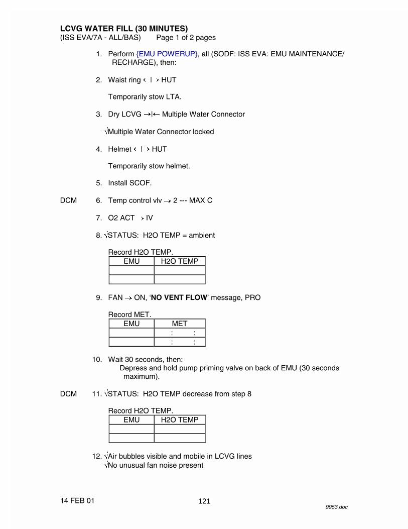
LCVG WATER FILL (30 MINUTES) (ISS EVA/7A - ALL/BAS) Page 1 of 2 pages
14 FEB 01 9953.doc
1. Perform {EMU POWERUP}, all (SODF: ISS EVA: EMU MAINTENANCE/ RECHARGE), then:
2. Waist ring �|� HUT
Temporarily stow LTA. 3. Dry LCVG �|� Multiple Water Connector
�Multiple Water Connector locked 4. Helmet �|� HUT
Temporarily stow helmet. 5. Install SCOF. DCM 6. Temp control vlv � 2 --- MAX C 7. O2 ACT � IV 8. �STATUS: H2O TEMP = ambient
Record H2O TEMP. EMU H2O TEMP
9. FAN � ON, ‘NO VENT FLOW’ message, PRO
Record MET. EMU MET
: : : :
10. Wait 30 seconds, then:
Depress and hold pump priming valve on back of EMU (30 seconds maximum).
DCM 11. �STATUS: H2O TEMP decrease from step 8
Record H2O TEMP. EMU H2O TEMP
12. �Air bubbles visible and mobile in LCVG lines
�No unusual fan noise present
121

LCVG WATER FILL (30 MINUTES) (ISS EVA/7A - ALL/BAS) Page 2 of 2 pages
14 FEB 01 9953.doc
If no H2O TEMP decrease or no H2O flow detected in LCVG or if an unusual fan noise is present
13. Depress and hold pump priming vlv on back of EMU (30 seconds max).
14. Repeat step 13 during fill as required.
When no air bubbles visible in LCVG lines DCM 15. FAN � OFF
Record MET. EMU MET
: : : :
16. O2 ACT � OFF 17. Perform {EMU WATER RECHARGE}, all (SODF: ISS EVA: EMU
MAINTENANCE/RECHARGE), then: 18. Remove SCOF.
Install helmet. 19. LCVG �|� Multiple Water Connector
Stow LCVG in HUT. 20. Waist ring �|� HUT 21. Go to {EMU POWERDOWN} (SODF: ISS EVA: EMU MAINTENANCE/
RECHARGE).
122

EMU WATER RECHARGE (ISS EVA/7A - ALL/BAS) Page 1 of 2 pages
06 FEB 01 9954.doc
INITIATE E-Lk 1. Unstow EMU Water Recharge Bag from floor bin.
Attach bag to wall below IRU. Log new stowage location for bag in IMS.
IRU 2. EMU Water Recharge Bag �|� H2O IN port 3. �H2O outlet vlv (rotary) � CLOSED 4. If EMU not powered, perform {EMU POWERUP}, all (SODF: ISS EVA:
EMU MAINTENANCE/RECHARGE), then: UIA 5. �WATER EV-1,2 REG vlv (two) � SUPPLY 6. WATER EV-1,2 SUPPLY vlv (two) � OPEN PSA 7. IRU/UTILITY POWER sw � ON
�IRU/UTILITY POWER LED � �IRU volts: 27.0 --- 29.0
IRU 8. POWER sw � ON
�POWER, PRESS, TEMP LEDs (three) � at startup 9. Wait until 2.5 second LED and pixel check complete.
�POWER LED remains � 10. H2O outlet vlv (rotary) EMU SUPPLY. 11. PUMP sw � ON
�PUMP LED � 12. �QUANTITY display � �
TERMINATE DCM 13. �STATUS: H2O WP ~13.5 psi, stable for ~30 seconds (indicates charging
complete) UIA 14. WATER EV-1,2 SUPPLY vlv (two) � CLOSE IRU 15. PUMP sw � OFF
�PUMP LED � 16. H2O outlet vlv (rotary) CLOSED.
123
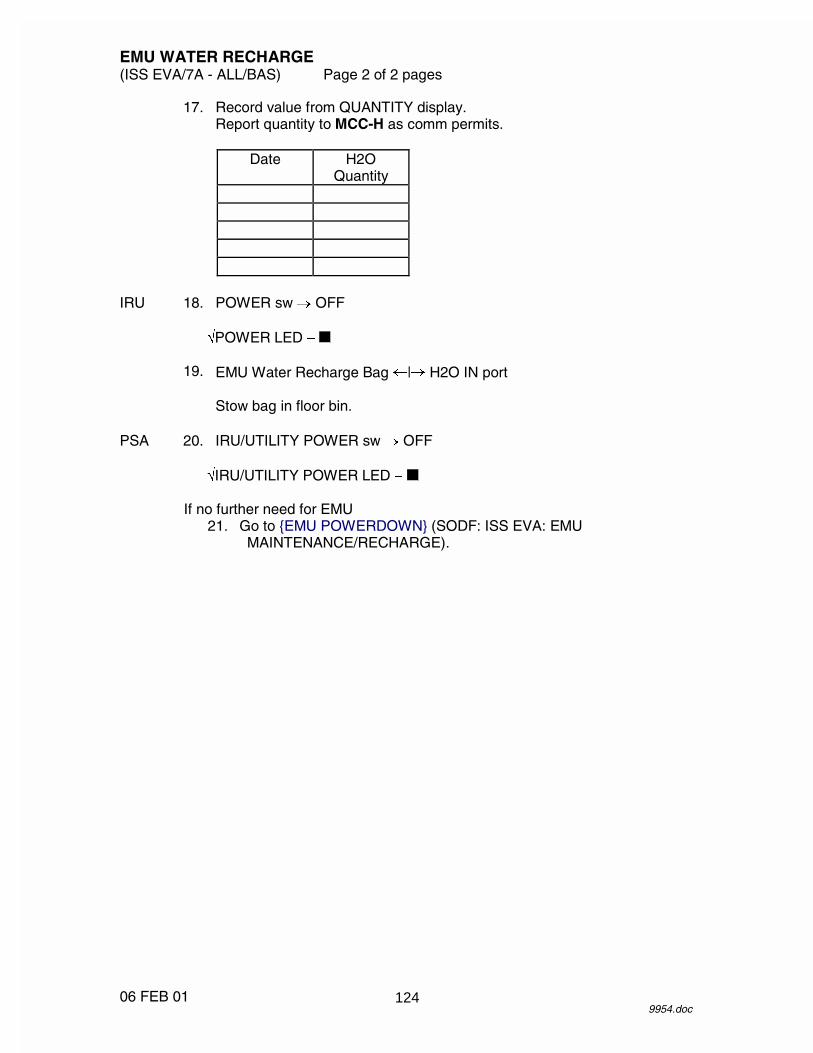
EMU WATER RECHARGE (ISS EVA/7A - ALL/BAS) Page 2 of 2 pages
06 FEB 01 9954.doc
17. Record value from QUANTITY display. Report quantity to MCC-H as comm permits.
Date H2O
Quantity
IRU 18. POWER sw � OFF
�POWER LED � 19. EMU Water Recharge Bag �|� H2O IN port
Stow bag in floor bin. PSA 20. IRU/UTILITY POWER sw � OFF
�IRU/UTILITY POWER LED �
If no further need for EMU 21. Go to {EMU POWERDOWN} (SODF: ISS EVA: EMU
MAINTENANCE/RECHARGE).
124

EMU METOX/BATTERY REPLACEMENT (20 MINUTES) (ISS EVA/7A - ALL/BAS) Page 1 of 1 page
14 FEB 01 9955.doc
NOTE When handling the Metox canister, take caution to protect the state indicator from being inadvertently switched to the E position.
1. Unstow new Metox canisters and EMU batteries as required.
√Metox state indicator − R 2. Rotate EDDA open. PLSS 3. Unzip thermal cover.
Velcro thermal cover to top of EMU. 4. Remove used Metox canister.
√Used Metox state indicator − E
If EMU battery to be replaced UIA 5. PWR EV-1,2 sw (two) → OFF DCM 6. √PWR − SCU 7. Remove used battery. 8. Install new battery.
√Connector alignment 9. Engage latch. 10. Remove caps from new Metox canister (two per canister). 11. Install Metox using label on canister for proper orientation.
Latch canister in place. 12. Log new stowage location for Metox canisters and EMU batteries in IMS. PLSS 13. Close thermal cover zipper. 14. Rotate EDDA closed. 15. Place caps on used Metox canisters.
Temporarily stow used canisters and batteries for future regeneration/ recharge.
125

26 APR 01
This Page Intentionally Blank
126
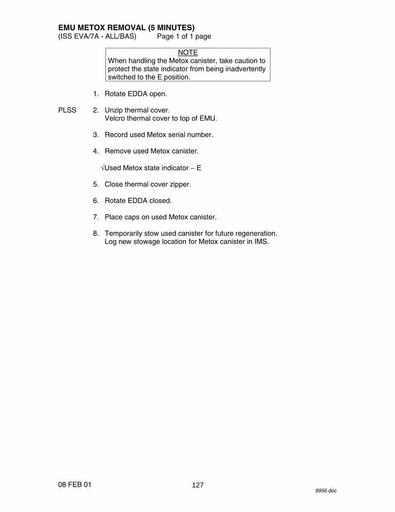
EMU METOX REMOVAL (5 MINUTES) (ISS EVA/7A - ALL/BAS) Page 1 of 1 page
08 FEB 01 9956.doc
NOTE When handling the Metox canister, take caution to protect the state indicator from being inadvertently switched to the E position.
1. Rotate EDDA open. PLSS 2. Unzip thermal cover.
Velcro thermal cover to top of EMU. 3. Record used Metox serial number. 4. Remove used Metox canister.
√Used Metox state indicator − E 5. Close thermal cover zipper. 6. Rotate EDDA closed. 7. Place caps on used Metox canister. 8. Temporarily stow used canister for future regeneration.
Log new stowage location for Metox canister in IMS.
127

26 APR 01
This Page Intentionally Blank
128

REBA INSTALLATION (10 MINUTES) (ISS EVA/7A - ALL/BAS) Page 1 of 1 page
08 FEB 01 9958.doc
1. Unstow REBA. 2. Rotate EDDA to access back of EMU. 3. Remove REBA J1 connector cover. 4. Install REBA on EMU. 5. Configure REBA pull tabs. 6. √REBA sw (two) − OFF 7. EMU power harness →|← REBA (P1/J1) 8. Log new location of REBA in IMS. 9. Rotate EDDA closed.
129

26 APR 01
This Page Intentionally Blank
130
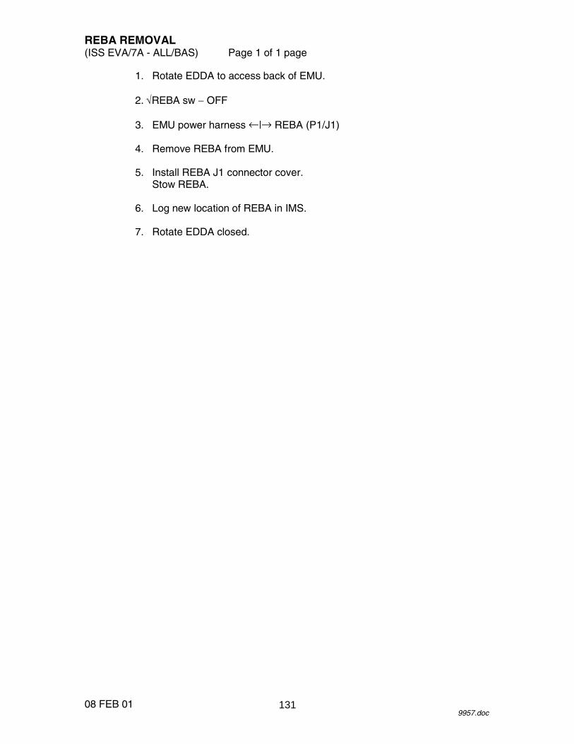
REBA REMOVAL (ISS EVA/7A - ALL/BAS) Page 1 of 1 page
08 FEB 01 9957.doc
1. Rotate EDDA to access back of EMU. 2. √REBA sw − OFF 3. EMU power harness ←|→ REBA (P1/J1) 4. Remove REBA from EMU. 5. Install REBA J1 connector cover.
Stow REBA. 6. Log new location of REBA in IMS. 7. Rotate EDDA closed.
131

26 APR 01
This Page Intentionally Blank
132
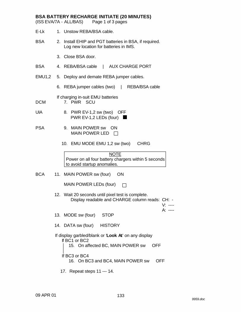
BSA BATTERY RECHARGE INITIATE (20 MINUTES) (ISS EVA/7A - ALL/BAS) Page 1 of 3 pages
09 APR 01 9959.doc
E-Lk 1. Unstow REBA/BSA cable. BSA 2. Install EHIP and PGT batteries in BSA, if required.
Log new location for batteries in IMS. 3. Close BSA door. BSA 4. REBA/BSA cable →|← AUX CHARGE PORT EMU1,2 5. Deploy and demate REBA jumper cables. 6. REBA jumper cables (two) →|← REBA/BSA cable
If charging in-suit EMU batteries DCM 7. √PWR − SCU UIA 8. √PWR EV-1,2 sw (two) − OFF
√PWR EV-1,2 LEDs (four) − PSA 9. √MAIN POWER sw − ON
√MAIN POWER LED − 10. EMU MODE EMU 1,2 sw (two) → CHRG
NOTE Power on all four battery chargers within 5 seconds to avoid startup anomalies.
BCA 11. MAIN POWER sw (four) → ON
√MAIN POWER LEDs (four) → 12. Wait 20 seconds until pixel test is complete.
√Display readable and CHARGE column reads: CH: - V: ---- A: ----
13. MODE sw (four) → STOP 14. DATA sw (four) → HISTORY
If display garbled/blank or ‘Look At’ on any display If BC1 or BC2
15. On affected BC, MAIN POWER sw → OFF
If BC3 or BC4 16. On BC3 and BC4, MAIN POWER sw → OFF 17. Repeat steps 11 --- 14.
133

BSA BATTERY RECHARGE INITIATE (20 MINUTES) (ISS EVA/7A - ALL/BAS) Page 2 of 3 pages
09 APR 01 9959.doc
18. Verify channel profile according to Table 1 by toggling DATA sw → HISTORY
Table 1. Initial BC Channel Profiles
BC 1 BC 2 Ch
Number Battery Type Charge
History Ch
Number Battery Type Charge
History CH 1 09PGT No History CH 1 03HL-A No History CH 2 04HL-B No History CH 2 07HL-B No History CH 3 03HL-A No History CH 3 06PGT No History CH 4 04HL-B No History CH 4 06PGT No History CH 5 03HL-A No History CH 5 06PGT No History
CH 6 03HL-A No History CH 6 06PGT No History
BC 3 BC 4 Ch
Number Battery Type Charge
History Ch
Number Battery Type Charge
History CH 1 02EMU SUIT No History CH 1 02EMU SUIT No History CH 2 08REBA-30 No History CH 2 08REBA-30 No History CH 3 04HL-B No History CH 3 04HL-B No History CH 4 01EMU BSA No History CH 4 01EMU BSA No History CH 5 05REBA-10 No History CH 5 05REBA-10 No History CH 6 05REBA-10 No History CH 6 05REBA-10 No History
If charging in-suit EMU batteries
UIA 19. PWR EV-1, 2 sw (two) → ON BCA 20. MODE sw (four) → CHARGE 21. Verify initial charge displays according to Table 2.
Table 2. BC Initial Charge Displays (minimum voltage values) BC1: CHARGE CHAN:VOLT BC2: CHARGE CHAN:VOLT
CH:1 1: -- 4: 18.0 CH:1 1: -- 4: 36.0 V: 36.0 2: 18.0 5: 18.0 V: 18.0 2: 18.0 5: 36.0 A: 0.55 3: 18.0 6: 18.0 A: 1.00 3: 36.0 6: 36.0
BC3: CHARGE CHAN:VOLT BC4: CHARGE CHAN:VOLT CH:1 1: -- 4: 0.0 CH:1 1: -- 4: 0.0 V: 17.5 2: 36.0 5: 12.0 V: 17.5 2: 36.0 5:12.0 A: 1.55 3: 18.0 6: 12.0 A: 1.55 3: 18.0 6:12.0
134

BSA BATTERY RECHARGE INITIATE (20 MINUTES) (ISS EVA/7A - ALL/BAS) Page 3 of 3 pages
09 APR 01 9959.doc
135

26 APR 01
This Page Intentionally Blank
136

BSA BATTERY RECHARGE TERMINATE (10 MINUTES) (ISS EVA/7A - ALL/BAS) Page 1 of 2 pages
14 FEB 01 10090.doc
BCA 1. √Charged/Look At display toggling
Record channels listed in “Look At” section.
BC 1 BC 2 BC 3 BC 4 CH #
2. MODE sw (four) → STOP BSA 3. √Charge In Progress LED − BCA 4. √Display CHARGE column reads: CH: -
V: ---- A: ----
5. DATA sw (four) → HISTORY 6. Verify channel profile according to Table 1.
Table 1. Final BC channel histories BC 1 BC 2
Ch Number
Battery Type Charge History Ch Number
Battery Type Charge History
CH 1 09PGT Task Completed - OK CH 1 03HL-A Task Completed - OK CH 2 10HL-B Task Completed - OK CH 2 11HL-B Task Completed - OK CH 3 03HL-A Task Completed - OK CH 3 06PGT Task Completed - OK CH 4 10HL-B Task Completed - OK CH 4 06PGT Task Completed - OK CH 5 03HL-A Task Completed - OK CH 5 06PGT Task Completed - OK CH 6 03HL-A Task Completed - OK CH 6 06PGT Task Completed - OK
BC 3 BC 4 Ch
Number Battery Type Charge History Ch
Number Battery Type Charge History
CH 1 02EMU SUIT Task Completed - OK CH 1 02EMU SUIT Task Completed - OK CH 2 08REBA-30 Task Completed - OK CH 2 08REBA-30 Task Completed - OK CH 3 10HL-B Task Completed - OK CH 3 10HL-B Task Completed - OK CH 4 01EMU BSA Batt-circuit open CH 4 01EMU BSA Batt-circuit open CH 5 05REBA-10 Task Completed - OK CH 5 05REBA-10 Task Completed - OK CH 6 05REBA-10 Task Completed - OK CH 6 05REBA-10 Task Completed - OK BCA 7. MAIN POWER sw (four) → OFF
√MAIN POWER LEDs (four) − EMU1,2 8. REBA/BSA cables (two) ←|→ REBA jumper cables 9. Mate and stow REBA jumper cables. BSA 10. REBA/BSA cable ←|→ AUX CHARGE PORT
Stow REBA/BSA cable.
137

BSA BATTERY RECHARGE TERMINATE (10 MINUTES) (ISS EVA/7A - ALL/BAS) Page 2 of 2 pages
14 FEB 01 10090.doc
If charging in-suit EMU batteries, perform the following as required UIA 11. PWR EV-1,2 sw (two) − OFF
√PWR EV-1,2 LEDs (four) − PSA 12. EMU MODE EMU 1,2 sw (two) → PWR 13. MAIN POWER sw → OFF
√MAIN POWER LED − DCM 14. SCU ←|→ DCM 15. Install DCM cover. C-Lk wall 16. Insert SCU in stowage pouch.
138

IN-SUIT EMU BATTERY RECHARGE INITIATE (10 MINUTES) (ISS EVA/7A - ALL/BAS) Page 1 of 2 pages
09 APR 01 9960.doc
If SCU not connected to DCM UIA 1. √PWR EV-1,2 sw (two) → OFF
√PWR EV-1,2 LEDs (four) − √EMU O2 SUPPLY PRESS gauge: 850 --- 950
C-Lk wall 2. Remove SCU from stowage straps and pouches.
Transfer SCU to E-Lk. DCM 3. Remove DCM Cover.
Velcro to DCM. 4. SCU →|← DCM
√SCU Locked 5. √PWR − SCU PSA 6. √EMU MODE EMU 1,2 sw (two) − PWR
√SUIT SELECT sw (two) − OFF √SUIT SELECT LEDs (four) −
7. MAIN POWER sw → ON
√MAIN POWER LED − 8. EMU MODE EMU 1,2 sw (two) → CHRG
NOTE Power on both battery chargers within 5 seconds to avoid startup anomalies.
BC3,4 9. MAIN POWER sw (two) → ON 10. Wait 20 seconds until pixel test is complete.
√Display readable and CHARGE column reads: CH: - V: ---- A: ----
11. MODE sw (two) → STOP 12. DATA sw (two) → HISTORY
If display garbled/blank or ‘Look At ’ on any display BC3,4 13. On BC3 and BC4, MAIN POWER sw → OFF 14. Repeat steps 9 --- 12. 15. Verify channel profile according to Table 1 by toggling
DATA sw → HISTORY.
139
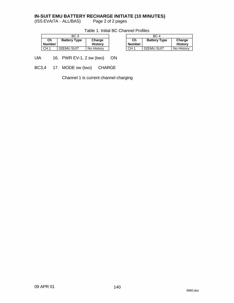
IN-SUIT EMU BATTERY RECHARGE INITIATE (10 MINUTES) (ISS EVA/7A - ALL/BAS) Page 2 of 2 pages
09 APR 01 9960.doc
Table 1. Initial BC Channel Profiles BC 3 BC 4
Ch Number
Battery Type Charge History
Ch Number
Battery Type Charge History
CH 1 02EMU SUIT No History CH 1 02EMU SUIT No History
UIA 16. PWR EV-1, 2 sw (two) → ON BC3,4 17. MODE sw (two) → CHARGE
√Channel 1 is current channel charging
140
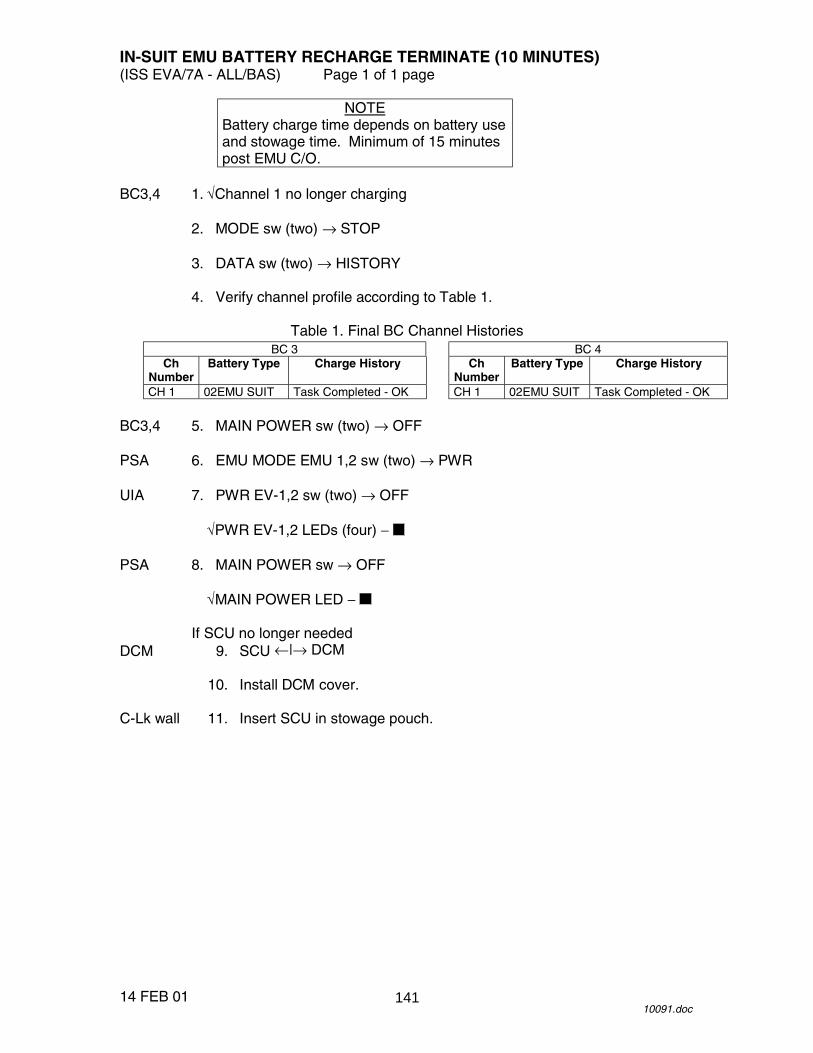
IN-SUIT EMU BATTERY RECHARGE TERMINATE (10 MINUTES) (ISS EVA/7A - ALL/BAS) Page 1 of 1 page
14 FEB 01 10091.doc
NOTE Battery charge time depends on battery use and stowage time. Minimum of 15 minutes post EMU C/O.
BC3,4 1. √Channel 1 no longer charging 2. MODE sw (two) → STOP 3. DATA sw (two) → HISTORY 4. Verify channel profile according to Table 1.
Table 1. Final BC Channel Histories BC 3 BC 4
Ch Number
Battery Type Charge History Ch Number
Battery Type Charge History
CH 1 02EMU SUIT Task Completed - OK CH 1 02EMU SUIT Task Completed - OK BC3,4 5. MAIN POWER sw (two) → OFF PSA 6. EMU MODE EMU 1,2 sw (two) → PWR UIA 7. PWR EV-1,2 sw (two) → OFF
√PWR EV-1,2 LEDs (four) − PSA 8. MAIN POWER sw → OFF
√MAIN POWER LED −
If SCU no longer needed DCM 9. SCU ←|→ DCM 10. Install DCM cover. C-Lk wall 11. Insert SCU in stowage pouch.
141

26 APR 01
This Page Intentionally Blank
142

EMU POWERDOWN (ISS EVA/7A - ALL/BAS) Page 1 of 1 page
14 FEB 01 9961.doc
NOTE Procedure is written for simultaneous powerdown of two EMUs.
EV1,2 DCM 1. √PWR − SCU UIA 2. PWR EV-1,2 sw (two) → OFF
√PWR EV-1,2 LEDs (four) − √PWR EV-1,2 VOLTS: ~00.0
PSA 3. SUIT SELECT sw (two) → OFF
√SUIT SELECT LEDs (four) − 4. MAIN POWER sw → OFF
√MAIN POWER LED − DCM 5. SCU ←|→ DCM 6. Install DCM cover. C-Lk wall 7. Insert SCU in stowage pouch.
143

26 APR 01
This Page Intentionally Blank
144
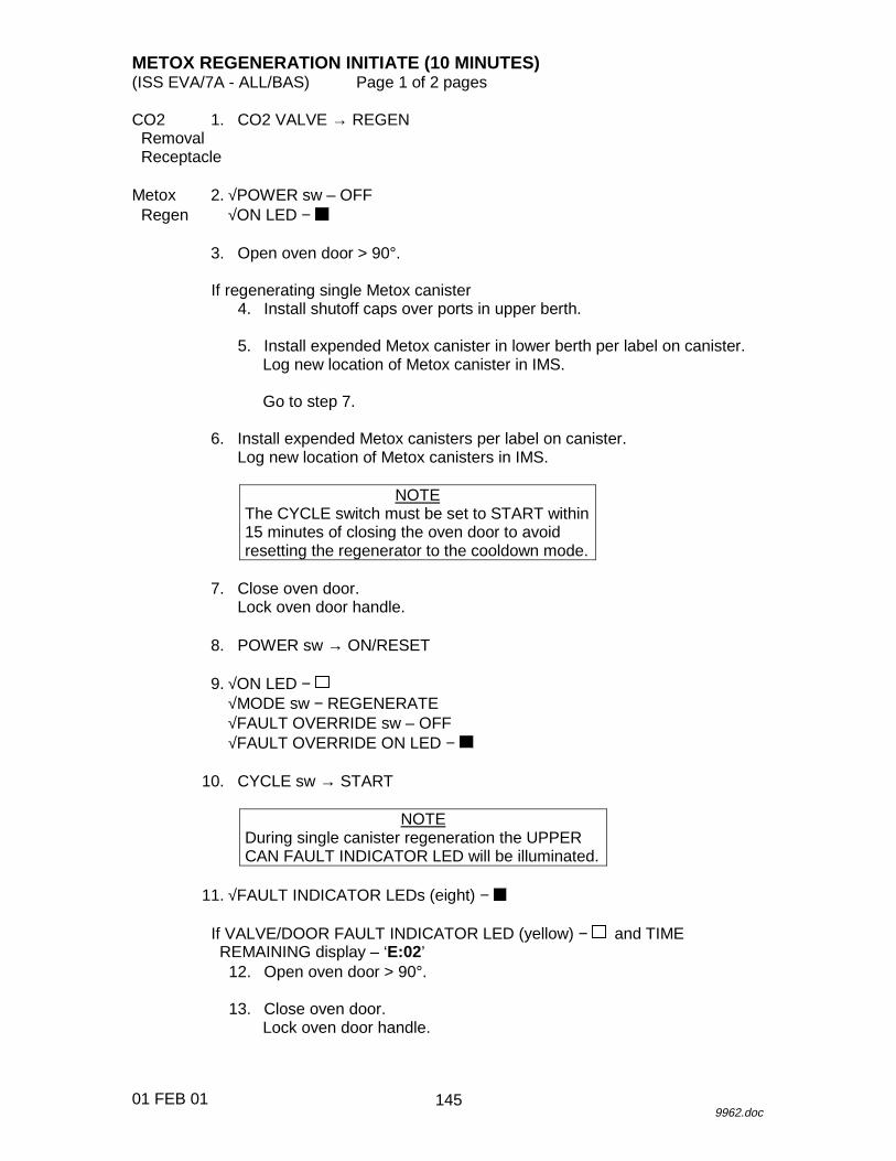
METOX REGENERATION INITIATE (10 MINUTES)(ISS EVA/7A - ALL/BAS) Page 1 of 2 pages
01 FEB 019962.doc
CO2 1. CO2 VALVE → REGEN Removal Receptacle
Metox 2. √POWER sw – OFF Regen √ON LED −
3. Open oven door > 90°.
If regenerating single Metox canister4. Install shutoff caps over ports in upper berth.
5. Install expended Metox canister in lower berth per label on canister.Log new location of Metox canister in IMS.
Go to step 7.
6. Install expended Metox canisters per label on canister.Log new location of Metox canisters in IMS.
NOTEThe CYCLE switch must be set to START within15 minutes of closing the oven door to avoidresetting the regenerator to the cooldown mode.
7. Close oven door.Lock oven door handle.
8. POWER sw → ON/RESET
9. √ON LED −√MODE sw − REGENERATE√FAULT OVERRIDE sw – OFF√FAULT OVERRIDE ON LED −
10. CYCLE sw → START
NOTEDuring single canister regeneration the UPPERCAN FAULT INDICATOR LED will be illuminated.
11. √FAULT INDICATOR LEDs (eight) −
If VALVE/DOOR FAULT INDICATOR LED (yellow) − and TIMEREMAINING display – ‘E:02’
12. Open oven door > 90°.
13. Close oven door.Lock oven door handle.
145
METOX REGENERATION INITIATE (10 MINUTES)(ISS EVA/7A - ALL/BAS) Page 2 of 2 pages
01 FEB 019962.doc
14. √REGENERATE HEATING LED −√TIME REMAINING display – ‘14:00’√TIME REMAINING display − ↓ (1-minute increments)
146

METOX REGENERATION TERMINATE (10 MINUTES) (EVA/7A - ALL/BAS) Page 1 of 1 page
11 APR 01 10092.doc
Metox 1. �REGENERATE COOLING LED � Regen �REGENERATE COMPLETE LED �
�TIME REMAINING display: 0:00 �No error codes displayed �OVEN HOT LED � �FAULT INDICATOR LEDs (eight) �
2. Open oven door. 3. Remove Metox canister(s). 4. Verify Metox state indicator � R
NOTE When handling the canister, take caution to protect the state indicator from being inadvertently switched to the E position.
5. Close oven door. 6. POWER sw � OFF 7. Unstow Metox canister caps from EMU Equipment Bag.
Install caps on regenerated canisters. Stow regenerated canisters.
8. Log new stowage location for Metox canisters in IMS. CO2 9. CO2 VALVE � REMOVAL Removal Receptacle
147

26 APR 01
This Page Intentionally Blank
148

METOX REGENERATION STANDBY (5 MINUTES) (ISS EVA/7A - ALL/BAS) Page 1 of 1 page
08 FEB 01 10093.doc
NOTE This procedure is used to temporarily suspend the heating cycle to conserve power.
Metox 1. MODE sw → STANDBY Regen 2. √STANDBY LOCAL LED −
√TIME REMAINING display – holding
NOTE If the standby phase exceeds 6 hours, regeneration is aborted and a 4 hr cooling cycle is initiated. (The CYCLE ABORT INITIATED LED will illuminate, followed by the CYCLE ABORT COMPLETE LED. The TIME REMAINING display will flash ‘E:06’.)
When standby no longer required
3. MODE sw → REGENERATE 4. √STANDBY LOCAL LED −
√REGENERATE HEATING LED −
NOTE The TIME REMAINING display will not decrease until the canister has reached the temperature it was at prior to standby initiation.
149

26 APR 01
This Page Intentionally Blank
150
HELMET LIGHT BULB CHANGEOUT (15 MINUTES)(ISS EVA/7A - ALL/BAS) Page 1 of 2 pages
01 FEB 019963.doc
NOTELight assembly has several loose pieces whichmay be spring loaded. Be prepared to capturethem during changeout.
CAUTIONHandle bulbs with care. Do not touch bulb withbare hands (could degrade bulb life span).
1. Remove helmet light battery from affected side of lights.Temporarily stow.
2. Obtain, don Comfort Glove.Obtain spare Flood Bulb/Spot Bulb Reflector.
3. Depress Faceplate.Open Faceplate Sliders (two) on affected side of lights.
4. Remove Faceplate.Remove Reflector Housing by pulling straight out.Remove affected bulbs as required.Stow used bulb.
5. Install new bulb.Log new stowage location for bulbs in IMS.
NOTEContacts on Spot Bulb may be difficult toreseat fully into socket.
6. Install Reflector Housing; seat Spot Bulb.
7. Install Faceplate.Lock Sliders (two).
8. Install helmet light battery.
√Helmet light ops
151
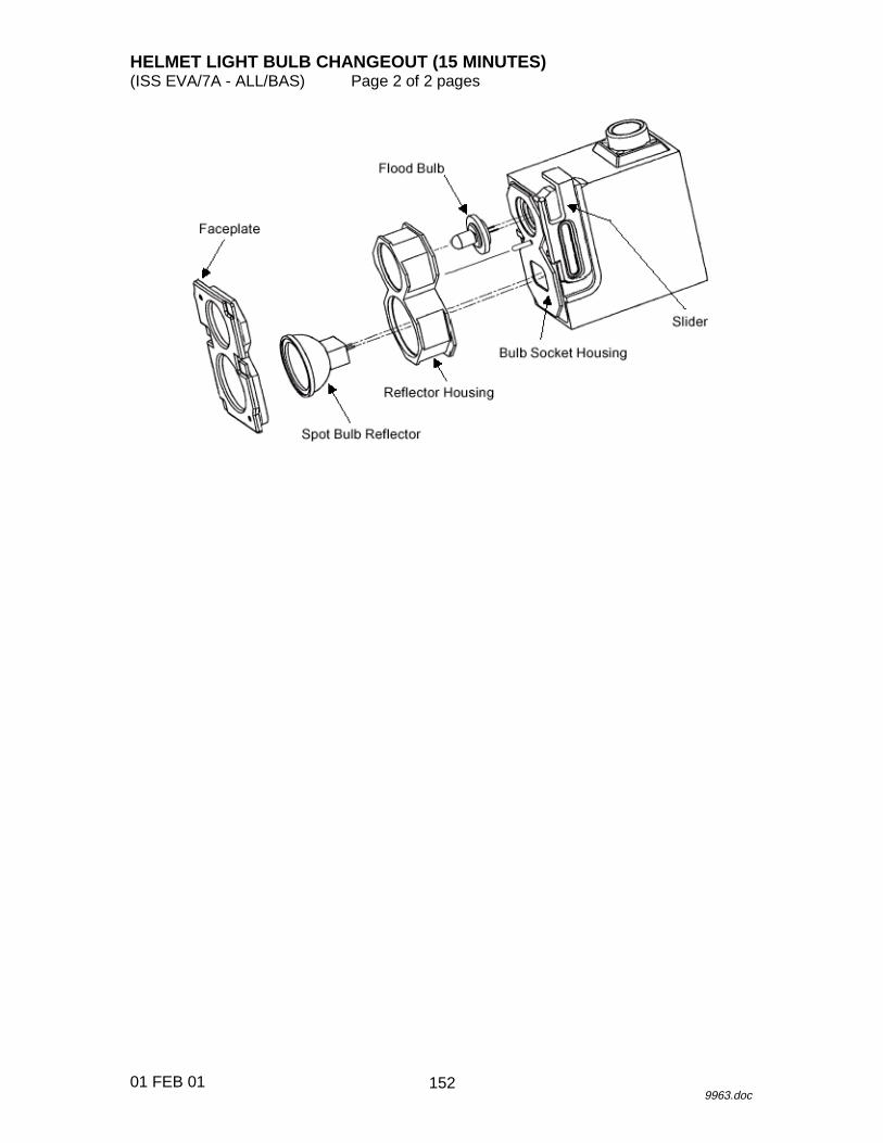
HELMET LIGHT BULB CHANGEOUT (15 MINUTES)(ISS EVA/7A - ALL/BAS) Page 2 of 2 pages
01 FEB 019963.doc
152
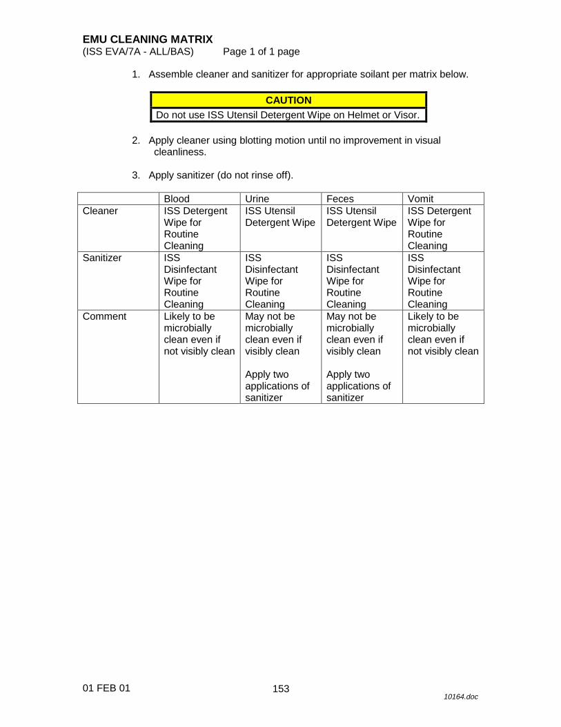
EMU CLEANING MATRIX(ISS EVA/7A - ALL/BAS) Page 1 of 1 page
01 FEB 0110164.doc
1. Assemble cleaner and sanitizer for appropriate soilant per matrix below.
CAUTIONDo not use ISS Utensil Detergent Wipe on Helmet or Visor.
2. Apply cleaner using blotting motion until no improvement in visualcleanliness.
3. Apply sanitizer (do not rinse off).
Blood Urine Feces VomitCleaner ISS Detergent
Wipe forRoutineCleaning
ISS UtensilDetergent Wipe
ISS UtensilDetergent Wipe
ISS DetergentWipe forRoutineCleaning
Sanitizer ISSDisinfectantWipe forRoutineCleaning
ISSDisinfectantWipe forRoutineCleaning
ISSDisinfectantWipe forRoutineCleaning
ISSDisinfectantWipe forRoutineCleaning
Comment Likely to bemicrobiallyclean even ifnot visibly clean
May not bemicrobiallyclean even ifvisibly clean
Apply twoapplications ofsanitizer
May not bemicrobiallyclean even ifvisibly clean
Apply twoapplications ofsanitizer
Likely to bemicrobiallyclean even ifnot visibly clean
153

26 APR 01
This Page Intentionally Blank
154

����������
��� ���������
��
��
��
�
��
��
�
��
��
��
155

����������
�
�������������������������������
��
��
��
�
��
��
�
��
��
��
156

DISPLAY LOSS DURING POWER TRANSFER (WARM RESTART) (ISS EVA/7A - ALL/BAS) Page 1 of 1 page
10 APR 01 9964.doc
DCM 1. FAN � OFF 2. �PWR – SCU UIA 3. PWR EV-1(2) sw � OFF
�PWR EV-1(2) EMU LED � (7 seconds) DCM 4. PWR � BATT 5. �DISPLAY � ‘O2 POS – XX ’
If no display 6. Contact MCC-H. UIA 7. PWR EV-1(2) sw � ON
�PWR EV-1(2) EMU LED � �PWR EV-1(2) VOLTS: 18.0 --- 19.0
DCM 8. PWR � SCU 9. �DISPLAY – ‘O2 POS �� XX’ 10. FAN � ON
157

26 APR 01
This Page Intentionally Blank
158

FAILED LEAK CHECK (5 PSI) (ISS EVA/7A - ALL/BAS) Page 1 of 1 page
24 APR 01 9965.doc
Repeat leak check on watch and gauge as follows (leaking EMU) EV DCM 1. O2 ACT � PRESS, until SUIT P = 4.2 --- 4.4 and stable,
compare with gauge 2. O2 ACT � IV (1 minute, maximum �P = 0.3 psi)
If leak check passed 3. EV CREW RETURN TO CREWLOCK DEPRESS/REPRESS
Cue Card, CREWLOCK DEPRESS, step 7 (suit pressure sensor unreliable) >>
IV CREW RETURN TO {CREWLOCK DEPRESS}, step 7 (SODF: ISS EVA: DEPRESS/REPRESS) >>
BOTH DCM 4. O2 ACT � IV IV 5. IV Hatch equalization valve � NORM PCS 6. CHECKING C-Lk TO E-Lk �P � 0.5 psi
EVA: AIRLOCK SYSTEMS AIRLOCK SYSTEMS
AIRLOCK PRESSURE SUMMARY
�C/L PRESS TO E/L PRESS �P � 0.5 psi, then: 7. IV Hatch � open 8. IV Hatch equalization valve � OFF 9. Repeat leak check as follows EV DCM 10. PURGE vlv � cl (dn) 11. O2 ACT � PRESS, until SUIT P = 4.2 --- 4.4 and stable,
compare with gauge 12. O2 ACT � IV 13. Start timing (1 minute, maximum �P = 0.3 psi). 14. Contact MCC-H.
159

26 APR 01
This Page Intentionally Blank
160

FAILED LEAK CHECK (14.7/10.2 PSI) (ISS EVA/7A - ALL/BAS) Page 1 of 2 pages
15 FEB 01 9966.doc
For leaking EMU EV DCM 1. O2 ACT � PRESS IV 2. Rotate lower arm assemblies one revolution. 3. �Suit arms aligned 4. �Sizing rings locked 5. Swivel hips from side to side. 6. Repeat leak check as follows EV 7. �Helmet purge vlv – cl, locked 8. �PURGE vlv – cl (dn) 9. �SUIT P: 4.2 --- 4.4 and stable (compare with gauge) 10. O2 ACT � IV, start timing, 1 minute (during EMU
CHECKOUT, 2 minutes) (maximum � P = 0.3 psi)
If leak check passed 11. Go to step 35.
If leak check failed 12. PURGE vlv � op (up) 13. O2 ACT � OFF 14. FAN � OFF (if EVA PREP) 15. Cycle/inspect suit disconnects as follows 16. Gloves 17. Helmet (leave disconnected) 18. LTA 19. FAN � ON (if EVA PREP) 20. Install Helmet. 21. Repeat leak check steps 6 --- 10.
161

FAILED LEAK CHECK (14.7/10.2 PSI) (ISS EVA/7A - ALL/BAS) Page 2 of 2 pages
15 FEB 01 9966.doc
If leak check passed 22. Go to step 35.
If leak check failed 23. PURGE vlv � op (up) 24. O2 ACT � OFF 25. FAN � OFF (if EVA PREP) 26. Cycle/inspect suit components 27. Gloves 28. Helmet (leave disconnected) 29. Helmet purge valve 30. Sizing rings 31. Metox/LiOH cartridge (O-rings) 32. FAN � ON (if EVA PREP) 33. Install Helmet. 34. Repeat leak check steps 6 --- 10.
If leak check passed 35. �Waist ring 36. �Wrist rings covered 37. Continue {EMU CHECKOUT} or {EVA PREP} >>
If leak check failed (EMU lost) 38. PURGE vlv � op (up) 39. Contact MCC-H.
Go to {POST EVA} (SODF: ISS EVA: POST EVA).
162

EMU WATER DUMP (ISS EVA/7A - ALL/BAS) Page 1 of 1 page
14 FEB 01 9967.doc
PCS 1. VERIFYING ISS WASTE WATER CONFIGURATION LAB: ECLSS: H2O Vent LAB Water Vent
�Water Vent System Status – Inhibited
If Water Vent System Status – Enabled, and Condensate Tank Qty 1(2) � 41.25 kg
2. Perform {USOS to RS WATER TRANSFER} (SODF: ECLSS: NOMINAL: WRM), then:
3. Perform {EMU POWERUP} (SODF: ISS EVA: EMU MAINTENANCE/
RECHARGE), then: E-Lk 4. Helmet �|� HUT
Temporarily stow helmet. 5. Install SCOF.
�SCOF locked DCM 6. O2 ACT � IV UIA 7. �WATER EV-1(2) SUPPLY vlv – CLOSE 8. WATER EV-1(2) REG vlv � WASTE DCM 9. �STATUS: H2O WP
When STATUS: H2O WP � 7.0 and stable for ~ 1 minute (indicates dump complete), then:
UIA 10. WATER EV-1(2) REG vlv � SUPPLY DCM 11. O2 ACT � OFF E-Lk 12. Remove SCOF.
Stow SCOF in EMU Equipment Bag. 13. Install helmet, as required. 14. Go to {EMU POWERDOWN} (SODF: ISS EVA: EMU
MAINTENANCE/RECHARGE).
163

26 APR 01
This Page Intentionally Blank
164

METOX REPLACEMENT (MANNED) (ISS EVA/7A - ALL/BAS) Page 1 of 2 pages
14 FEB 01 9968.doc
IV 1. Unstow new Metox canister.
√Metox state indicator − R PLSS 2. Unzip thermal cover.
Velcro thermal cover to top of EMU.
WARNING Fan will be off during changeout. Perform changeout as quickly as possible.
CAUTION
Vent loop is pressurized. Restrain Metox canister.
DCM 3. √O2 ACT – IV 4. Helmet purge vlv → op 5. FAN → OFF IV PLSS 6. Remove expended Metox canister.
√Expended Metox state indicator – E 7. Remove caps from new Metox canister (two per canister). 8. Install Metox using label on canister for proper orientation.
Latch canister in place. DCM 9. FAN → ON 10. Helmet purge vlv → cl, locked 11. O2 ACT → PRESS 12. PURGE vlv → op (up) 13. Begin timing 2-minute purge. 14. Log new stowage location for Metox canister in IMS. IV PLSS 15. Close thermal cover zipper. 16. Place caps on expended Metox canister.
Temporarily stow canister for future regeneration. Log new stowage location for Metox canister in IMS.
165

METOX REPLACEMENT (MANNED) (ISS EVA/7A - ALL/BAS) Page 2 of 2 pages
14 FEB 01 9968.doc
When purge time = 2 minutes DCM 17. PURGE vlv → cl (dn) 18. O2 ACT → IV
NOTE A minimum of 40 minutes of prebreathe is required to condition Metox canister.
19. Continue EVA PREP or EMU PREBREATHE with minimum of
40-minute prebreathe.
166

BATTERY REPLACEMENT (MANNED) (ISS EVA/7A - ALL/BAS) Page 1 of 2 pages
08 FEB 01 9969.doc
IV 1. Unstow new EMU battery. PLSS 2. Unzip thermal cover.
Velcro thermal cover to top of EMU.
WARNING 1. Power switch must be in SCU during battery
changeout. 2. Fan will be off during changeout. 3. Perform changeout as quickly as possible.
If no SCU power available
DCM 3. �O2 ACT – IV 4. Helmet purge vlv � op 5. FAN � OFF 6. PWR � SCU
If degraded/dead battery DCM 7. �PWR – SCU 8. �O2 ACT – IV 9. Helmet purge vlv � op 10. FAN � OFF
CAUTION 1. Vent loop is pressurized. 2. Hold Metox canister in place to prevent
breaking seal. PLSS 11. Rotate Metox canister outward. 12. Remove used battery. 13. Install new battery (�connector alignment).
Engage latch. 14. �Metox canister seated, rotate downward until latch pins engage
Latch canister in place.
167
BATTERY REPLACEMENT (MANNED) (ISS EVA/7A - ALL/BAS) Page 2 of 2 pages
08 FEB 01 9969.doc
If no SCU power available DCM 15. PWR � BATT 16. FAN � ON 17. Helmet purge vlv � cl, locked DCM 18. �STATUS: BATT VDC � 16.5 19. Log stowage location for new EMU battery in IMS. PLSS 20. Close thermal cover zipper. 21. Perform {EMU COLD RESTART} (SODF: ISS EVA: EMU
CONTINGENCY), then:
If Metox canister seal broken 22. Purge EMU, perform {METOX REPLACEMENT (MANNED)},
begin at step 11 (SODF: ISS EVA: EMU CONTINGENCY), then:
23. Continue EVA Prep.
168

SCU SWAP (MANNED) (ISS EVA/7A - ALL/BAS) Page 1 of 1 page
08 FEB 01 9970.doc
BOTH DCM 1. Temp control vlv → Max C 2. COMM mode → PRI 3. Comm FREQ → LOW 4. PWR → BATT UIA 5. PWR EV-1,2 sw (two) → OFF
√PWR EV-1,2 LEDs (four) − DCM 6. Swap SCUs. UIA 7. PWR EV-1,2 sw (two) → ON
√PWR EV-1,2 EMU LEDs (two) − √PWR EV-1,2 VOLTS: 18.0 --- 19.0
DCM 8. PWR → SCU 9. COMM mode → HL (as required) 10. Temp control vlv − as required
169

26 APR 01
This Page Intentionally Blank
170

SCU SWAP (UNMANNED) (ISS EVA/7A - ALL/BAS) Page 1 of 1 page
08 FEB 01 9971.doc
BOTH DCM 1. √FAN – OFF √O2 ACT – OFF √COMM mode – HL
If EMU on SCU PWR
UIA 2. PWR EV-1,2 sw (two) → OFF
√PWR EV-1,2 LEDs (four) − DCM 3. Swap SCUs. 4. PWR → BATT UIA 5. PWR EV-1,2 sw (two) → ON
√PWR EV-1,2 LEDs (four) − √PWR EV-1,2 VOLTS (two): 18.0 --- 19.0
DCM 6. PWR → SCU
If EMU on BATT PWR UIA 7. PWR EV-1,2 sw (two) → OFF
√PWR EV-1,2 LEDs (four) − DCM 8. Swap SCUs.
171

26 APR 01
This Page Intentionally Blank
172

EMU COLD RESTART (MANNED) (ISS EVA/7A - ALL/BAS) Page 1 of 1 page
08 FEB 01 9972.doc
WARNING This procedure should be used only at airlock pressures of 8.0 psi and higher. Fan and O2 will be off during restart. Perform restart as quickly as possible.
DCM 1. FAN → OFF 2. O2 ACT → OFF
If PWR – SCU 3. PWR → BATT
Wait 2 seconds. 4. PWR → SCU
If PWR – BATT 5. PWR → SCU
Wait 2 seconds. 6. PWR → BATT 7. O2 ACT → IV 8. FAN → ON
173

26 APR 01
This Page Intentionally Blank
174

EVA CHEMICAL DECONTAMINATION (ISS EVA/7A – ALL/BAS) Page 1 of 2 pages
18 APR 01 9973.doc
1
If leak is verified to be vapor only, per flight rules, contamination is only suspected. MCC will direct crew to perform blocks 7,8,10, then repress followed by blocks 12 through 15.
2
Bakeout should be performed for the remainder of orbit day.
3
During orbit night, the EMU should be in the Crewlock which is a warm environment. This raises the surface temperature of the EMU which increases the sublimation of the contaminant. Block 10 should be done only if more than 10 minutes of orbit night remain.
During EVA, When Crew Visually Detects Plume, White Crystals, or “Snow” Coming From Orbiter/Station.
When Orbiter/Station Chemical System Leak Suspected Due to Steady (not Step Function) Decrease in Pressure or Temperature.
1
Contamination visually detected on EMU or plume/crystals seen contacting the EMU?
2
EMU in thruster vicinity when leak detected visually or by orbiter/station instrumentation.
3 Confirmed contamination.
4 Suspected contamination.
No
Yes
5
• Notify MCC-H
6
• Brush off crystals Using hydr brush.
• Leave in Node bag.
7
• Continue EVA tasks not in vicinity of leak.
• As soon as practical, perform the following block.
1
8
When orbit day • Bakeout in Sun for full
orbit day.
Bakeout > 30 min?
2
9
On MCC-H GO For > 10 min of orbit night left • Perform {TERMINATE
EVA} (SODF: ISS EVA: CUFF C/L, 7), then:
10 min prior to orbit day. • Perform {CREWLOCK
EGRESS} (SODF: ISS EVA: CUFF C/L 42), then:
3
10
•√MCC-H for repeating blocks 8 and 9 based on EMU consumables
Additional bakeout?
9 10
No
Yes
8
8
11
Yes No
175

EVA CHEMICAL DECONTAMINATION (ISS EVA/7A – ALL/BAS) Page 2 of 2 pages
18 APR 01 9973.doc
4
The best action to dilute any remaining contaminant concentration is to establish intermodule ventilation between the airlock and rest of ISS.
11
• Perform {INGRESS} (Cuff C/L 43), all (SODF: EVA), then;
• Perform {PRE REPRESS} (ISS EVA: DEPRESS/REPRESS CUE CARD) all, then:
• Perform {REPRESS} (ISS EVA: DEPRESS/REPRESS CUE CARD), steps 1 and 3 --- 7, all (SODF: ISS EVA), then;
• Hold at 5.0 psi for 15 minutes.
TBD?
10
12
• Perform {CREWLOCK DEPRESS} (ISS EVA: DEPRESS/REPRESS CUE CARD) steps 9 --- 11, then:
When ∆P < 0.5 • EV Hatch → Partially
open (~ 2 in.) to draw a hard vacuum
• EV Hatch MPEV → CLOSED
• EV Hatch → Closed, Lock
• Perform {CREWLOCK REPRESS} (ISS EVA: DEPRESS/REPRESS Cue Card), steps 1 and 3 --- 7, then:
•√MCC-H for additional bakeout
Need for additional depress/repress cycles?
Yes
No
13
IV Crewmember • Perform {ATMOSPHERE
REVITALIZATION ACTIVATION} (ECLSS: NOMINAL), step 8, then;
• Perform {CCAA ACTIVATION} (ECLSS:A&C:THC ) for the airlock, then:
• ALCCAA → Full Cold • Lab CCAA → Full Cold • Install ATCO in CRK • Temporarily stow wet
towels and Ziplock Bags in E-Lk.
14
• IV crew don PBA. • IV crew activate CRK. • Continue {CREWLOCK REPRESS},
steps 9 --- 11 (ISS EVA: DEPRESS/REPRESS CUE CARD).
• IV crew egress E-Lk. • EV crew remain in EMUs • When ∆P < 0.5: • IV crew: Close Node 1 Stbd Hatch per
decal • IV Hatch → Open, start timer • EV crew wipe down EMUs, C-Lk, and E-Lk
with towels, seal in Ziploc Bags • Rotate IMV vent duct into C-Lk • IV crew ensure hatches to all other modules
are open. • IV crew don long sleeves, long pants, and
gloves, as practical. When TBD min of CRK scrubbing complete, then: • Open Node 1 Stbd Hatch per decal. •√MCC-H
No
Yes
4
15
• Repeat block 12.
176
SAFER BATTERY CHANGEOUT (15 MINUTES) (ISS EVA/7A - ALL/BAS) Page 1 of 1 page
08 FEB 01 9974.doc
1. Unstow new battery. PM 2. �Inhibitor installed
�MAN ISOL vlv – CL (up) HCM 3. �PWR � OFF PM 4. Loosen screws (eight) using 9/64" Hex Wrench. 5. Remove battery. 6. Battery umbilical connector �|� SAFER 7. Stow used battery. 8. Record new battery serial number on SAFER CHECKOUT RESULTS
Cue Card. Log new stowage location for SAFER battery in IMS.
9. Battery umbilical connector �|� SAFER
Install battery. 10. Tighten screws (eight). 11. Go to {SAFER CHECKOUT} (SODF: ISS EVA: CHECKOUTS).
177

26 APR 01
This Page Intentionally Blank
178

SAFER STATUS TROUBLESHOOTING (ISS EVA/7A - ALL/BAS) Page 1 of 1 page
24 FEB 01 9975.doc
GMT NOMINAL
STATUS GN2 % 87 --- 99 % PWR % 45 --- 99 % TANK P > 6575 psia TANK T -40 --- 140� F RATE R � 30 deg/s RATE P � 30 deg/s RATE Y � 30 deg/s DISPL R � 99.9 deg DISPL P � 99.9 deg DISPL Y � 99.9 deg BATT V � 35.0 V BATT T 50 --- 90� F Leak NO LEAK
GMT NOMINAL
STATUS GN2 % 87 --- 99 % PWR % 45 --- 99 % TANK P > 6575 psia TANK T -40 --- 140� F RATE R � 30 deg/s RATE P � 30 deg/s RATE Y � 30 deg/s DISPL R � 99.9 deg DISPL P � 99.9 deg DISPL Y � 99.9 deg BATT V � 35.0 V BATT T 50 --- 90� F Leak NO LEAK
SAFER JET NOMENCLATURE
179

26 APR 01
This Page Intentionally Blank
180

BENDS TREATMENT ADAPTER INSTALLATION (POST SUIT DOFFING) (ISS EVA/7A - ALL/BAS) Page 1 of 5 pages
25 APR 01 9977.doc
BTA PREP 1. Unstow BTA with 3/8" Wrench. PLSS 2. Cut/break TMG tacks.
Refer to Figure 2. 3. Unzip PLSS TMG (avoid pulling on antenna cable). 4. Remove Impact Shield.
Disconnect or cut hatch marked cable P3. Refer to Figure 2.
5. Remove Test Port F Plug on SOP using 3/8" end of BTA Wrench
(4 --- 6 turns ). Refer to Figure 1.
Figure 1.- Secondary Oxygen Package. BTA 6. Stow Test Port F Plug on BTA.
Refer to Figure 2.
If Metox canister replacement required by MCC-H 7. Unstow new Metox canister. 8. �Metox state indicator – R 9. Remove used Metox canister. 10. �Expended Metox state indicator – E 11. Install new Metox canister using label on canister for proper
orientation.
Log new stowage locations for canisters in IMS. 12. Install caps on used Metox canister.
Temporarily stow canister for future regeneration.
181

BENDS TREATMENT ADAPTER INSTALLATION (POST SUIT DOFFING) (ISS EVA/7A - ALL/BAS) Page 2 of 5 pages
25 APR 01 9977.doc
BTA TREATMENT 13. �SCU �|� DCM BTA 14. Unstow Poppet Keeper Screw from BTA. PLSS 15. Open Positive Pressure Relief Valve (PPRV) using BTA poppet keeper
(thread , pull, tighten nut). Refer to Figure 2.
16. BTA �|� PPRV ( )
�BTA Locked 17. Don MAG, LCVG, biomed. 18. Fill Drink Bag, remove gas, and insert bag in Restraint Bag.
Install Drink Bag, Restraint Bag in HUT. Dispose of fill tool in EMU Equipment Bag trash.
UIA 19. �OXYGEN EMU 1(2) vlv � OPEN DCM 20. PWR � BATT
CAUTION EMU must be on BATT pwr when UIA suit power is turned on.
PSA 21. �EMU MODE EMU1(2) sw � PWR 22. MAIN POWER sw � ON
�MAIN POWER LED � 23. SUIT SELECT sw � EMU 1(2)
�EMU 1(2) LED � �EMU 1(2) Volts: 18.0 --- 19.0
UIA 24. PWR EV-1(2) sw � ON
�PWR EV-1(2) EMU LED � DCM 25. PWR � SCU 26. �Waist ring – op 27. Don LTA (attach donning handles as required).
182

BENDS TREATMENT ADAPTER INSTALLATION (POST SUIT DOFFING) (ISS EVA/7A - ALL/BAS) Page 3 of 5 pages
25 APR 01 9977.doc
28. �Suit arms aligned �Wrist disconnects – op
29. Don thumb loops. 30. �Biomed connector outside of HUT 31. Don HUT.
Release thumb loops. 32. �Suit arms aligned 33. Don comm cap. 34. �COMM mode – HL (vol as required)
If biomed downlink desired 35. Perform {EVA COMM CONFIG} (SODF: ISS EVA: EVA PREP), then: DCM 36. COMM mode � PRI 37. Comm FREQ � LOW 38. Biomed �|� electrical harness 39. LCVG �|� Multiple Water Connector
�Multiple Water Connector locked 40. �Thermal cover clear of waist ring 41. Waist ring � engage position
Waist ring �|� HUT
�Waist ring locked 42. Wrist ring � engage position 43. Don EV gloves.
�EV gloves locked 44. �Electrical harness clear of neck ring 45. �Mic boom position DCM 46. FAN � ON 47. Don helmet.
�Helmet locked
183
BENDS TREATMENT ADAPTER INSTALLATION (POST SUIT DOFFING) (ISS EVA/7A - ALL/BAS) Page 4 of 5 pages
25 APR 01 9977.doc
48. �Helmet purge vlv – cl, locked 49. �PURGE vlv – op 50. O2 ACT � PRESS, begin purge clock (12 minutes)
Record start of purge clock.
GMT (PURGE START) _____/_____:_____ _____
UIA 51. �WATER EV-1(2) SUPPLY vlv – CLOSE 52. WATER EV-1(2) REG vlv � WASTE
When 12 minute purge complete 53. WATER EV-1(2) REG vlv � SUPPLY
GMT (PURGE END) _____/_____:_____ _____
DCM 54. PURGE vlv � cl (dn) 55. �SUIT P: 4.2 --- 4.4 56. O2 ACT � OFF (until SUIT P stabilizes) 57. O2 ACT � PRESS (for 15 seconds) 58. Repeat steps 56, 57 until SUIT P = 6.0 psig on BTA gauge.
NOTE BTA relief valve relieves at 8.04 --- 8.45 psig.
59. Repeat steps 56, 57 as required to maintain SUIT P = 6.0 psig. 60. Contact Surgeon (MCC-H) for treatment length and changes in treatment
pressure.
184

BENDS TREATMENT ADAPTER INSTALLATION (POST SUIT DOFFING) (ISS EVA/7A - ALL/BAS) Page 5 of 5 pages
25 APR 01 9977.doc
Nut
Poppet keeper screww/o BTA
Positive pressure relief valve
Gauge
w/BTA
Relief valve
``Test port F''Stow port
Blackalignmentstripe
Tacks
Figure 2.- BTA Location on EMU.
P3 connector
185

26 APR 01
This Page Intentionally Blank
186
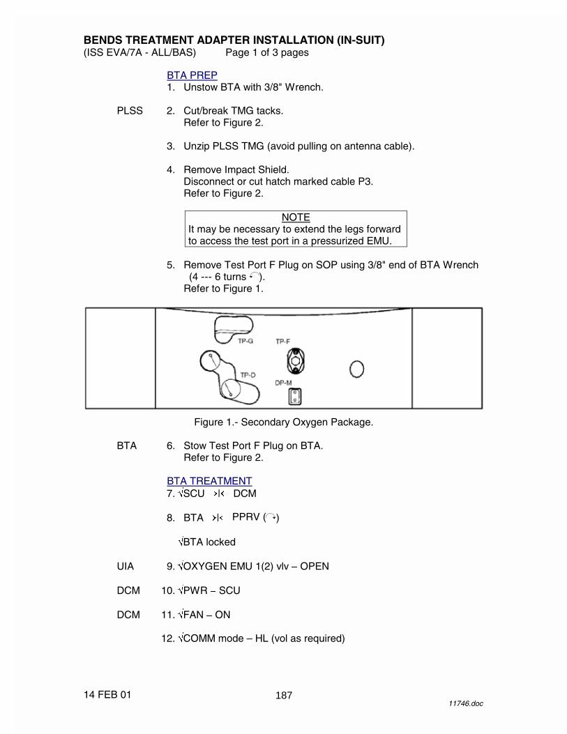
BENDS TREATMENT ADAPTER INSTALLATION (IN-SUIT) (ISS EVA/7A - ALL/BAS) Page 1 of 3 pages
14 FEB 01 11746.doc
BTA PREP 1. Unstow BTA with 3/8" Wrench. PLSS 2. Cut/break TMG tacks.
Refer to Figure 2. 3. Unzip PLSS TMG (avoid pulling on antenna cable). 4. Remove Impact Shield.
Disconnect or cut hatch marked cable P3. Refer to Figure 2.
NOTE
It may be necessary to extend the legs forward to access the test port in a pressurized EMU.
5. Remove Test Port F Plug on SOP using 3/8" end of BTA Wrench
(4 --- 6 turns ). Refer to Figure 1.
Figure 1.- Secondary Oxygen Package. BTA 6. Stow Test Port F Plug on BTA.
Refer to Figure 2.
BTA TREATMENT 7. �SCU �|� DCM 8. BTA �|� PPRV ( )
�BTA locked UIA 9. �OXYGEN EMU 1(2) vlv � OPEN DCM 10. �PWR � SCU DCM 11. �FAN � ON 12. �COMM mode – HL (vol as required)
187

BENDS TREATMENT ADAPTER INSTALLATION (IN-SUIT) (ISS EVA/7A - ALL/BAS) Page 2 of 3 pages
14 FEB 01 11746.doc
If biomed downlink desired DCM 13. COMM mode � PRI (ALT) 14. Comm FREQ � LOW UIA 15. �WATER EV-1(2) SUPPLY vlv – CLOSE 16. WATER EV-1(2) REG vlv � WASTE (until H2O Wp < 7 and
stable for ~ 1 minute) 17. WATER EV-1(2) REG vlv � SUPPLY IV DCM 18. Monitor BTA gauge while operating O2 actuator. 19. �Suit P: 4.2 --- 4.4 20. O2 ACT � OFF (until suit P stabilizes)
CAUTION
If BTA gauge pressure increases while O2 ACT � PRESS, set O2 ACT � OFF immediately to prevent a hazardous condition; contact MCC. Note that the BTA gauge increases nominally when O2 ACT � OFF. Actual suit P = 4.7 --- 5.5 psi above gauge pressure.
NOTE
Initial treatment will be at 6 psid for cuff 2 and 3 and will be increased to 8 psid if symptoms do not resolve. Initial treatment for cuff 4 will be 8 psid.
21. O2 ACT � PRESS (for 15 seconds) 22. Repeat steps 20, 21 until suit P = 6.0 psid on DCM display
‘H2O GpXX.X’ with O2 ACT � OFF. 23. Repeat steps 20, 21 as required to maintain suit P = 6.0 psid. 24. Contact Surgeon (MCC-H) for treatment length and changes in
treatment pressure. 25. Once BTA treatment complete, carefully remove BTA.
188

BENDS TREATMENT ADAPTER INSTALLATION (IN-SUIT) (ISS EVA/7A - ALL/BAS) Page 3 of 3 pages
14 FEB 01 11746.doc
Nut
Poppet keeper screww/o BTA
Positive pressure relief valve
Gauge
w/BTA
Relief valve
``Test port F''Stow port
Blackalignmentstripe
Tacks
Figure 2.- BTA Location on EMU.
P3 connector
189

26 APR 01
This Page Intentionally Blank
190
DCM ORU CHANGEOUT (75 MINUTES) (ISS EVA/7A - ALL/BAS) Page 1 of 2 pages
25 APR 01 9978.doc
NOTES 1. The EMU should be powered down, removed from the
EDDA, and have the SCU disconnected for this procedure.
2. Location callouts are given from the perspective of a
crewmember in the EMU. 3. This is a standalone procedure for removal/installation
of the HUT. Assumes the replacement HUT is stowed without PLSS or DCM attached
1. Unstow the following ORU tools for HUT Changeout: TBD 1/4" Torque Limiting Drive
1/4" to 3/8" Adapter 1/4" Ballnose Hex Driver (3/8" Drive) 1/4" Drive Handle 3/8" Ratchet 3/8" Torque Wrench, set at 200 in-lbs 3/8" x 4" Extension 3/8" Universal Joint Drive 3/16" Hex Driver (3/8" Drive) 5/16" Open End Wrench 5/32" Hex Ballnose Driver (5") 7/64" Hex Driver (1/4" Drive) Lint Free Wipes (EMU Servicing Kit)
IFM Kit Wrist Grounding Strap Kapton Tape
DCM REMOVAL (30 MINUTES)
DCM 2. �O2 ACT � OFF �PWR – SCU
PSA 3. �SUIT SELECT sw (two) � OFF
�SUIT SELECT LEDs (four) � PLSS 4. �REBA sw � OFF, if installed 5. �EMU installed in EDDA (LTA, helmet, lower arms, and gloves removed) 6. SCU �|� DCM 7. Perform {O2 LINE REMOVAL}, all (SODF: ISS EVA: EMU
CONTINGENCY PROCEDURES), then: 8. Perform {O2 ACTUATOR REMOVAL}, all (SODF: ISS EVA: EMU
CONTINGENCY PROCEDURES), then: 9. Perform {DCM REMOVAL}, all (SODF: ISS EVA: EMU CONTINGENCY
PROCEDURES), then:
191

DCM ORU CHANGEOUT (75 MINUTES) (ISS EVA/7A - ALL/BAS) Page 2 of 2 pages
25 APR 01 9978.doc
DCM INSTALLATION (45 MINUTES) 10. Perform {DCM INSTALLATION}, all (SODF: ISS EVA: EMU
CONTINGENCY PROCEDURES), then: 11. Perform {O2 LINE INSTALLATION}, all (SODF: ISS EVA: EMU
CONTINGENCY PROCEDURES), then: 12. Perform {O2 ACTUATOR INSTALLATION}, all (SODF: ISS EVA: EMU
CONTINGENCY PROCEDURES), then: 13. �HUT, DCM, PLSS hardware connected and restrained 14. Mate TMG on HUT, DCM, and PLSS interfaces.
192
PLSS ORU CHANGEOUT (60 MINUTES) (ISS EVA/7A - ALL/BAS) Page 1 of 2 pages
23 APR 01 9979.doc
NOTE 1. The EMU should be powered down, removed from the
EDDA, and have the SCU disconnected for this procedure.
2. Location callouts are given from the perspective of a
crewmember in the EMU. 3. This is a standalone procedure for removal/installation
of the HUT. Assumes the replacement HUT is stowed without PLSS or DCM attached.
1. Unstow the following ORU tools for HUT changeout: TBD 1/4" Torque Limiting Drive
1/4" to 3/8" Adapter 1/4" Ballnose Hex Driver (3/8" Drive) 1/4" Drive Handle 3/8" Ratchet 3/8" Torque Wrench, set at 200 in-lbs 3/8" x 4" Extension 3/8" Universal Joint Drive 3/16" Hex Driver (3/8" drive) 5/16" Open End Wrench 5/32" Hex Ballnose Driver (5") 7/64" Hex Driver (1/4" Drive) Lint-Free wipes (EMU Servicing Kit)
IFM kit Wrist Grounding Strap Kapton Tape
PLSS REMOVAL (30 MINUTES)
DCM 2. �O2 ACT � OFF �PWR – SCU
PSA 3. �SUIT SELECT sw (two) � OFF
�SUIT SELECT LEDs (four) � PLSS 4. �REBA sw � OFF, if installed 5. �EMU installed in EDDA (LTA, helmet, lower arms, and gloves removed) 6. SCU �|� DCM 7. Perform {O2 LINE REMOVAL}, all (SODF: ISS EVA: EMU
CONTINGENCY PROCEDURES), then: 8. Perform {O2 ACTUATOR REMOVAL}, all (SODF: ISS EVA: EMU
CONTINGENCY PROCEDURES), then: 9. Perform {HUT/PLSS DISCONNECTION}, all (SODF: ISS EVA: EMU
CONTINGENCY PROCEDURES), then:
193

PLSS ORU CHANGEOUT (60 MINUTES) (ISS EVA/7A - ALL/BAS) Page 2 of 2 pages
23 APR 01 9979.doc
PLSS INSTALLATION (30 MINUTES) 10. Perform {HUT/PLSS CONNECTION}, all (SODF: ISS EVA: EMU
CONTINGENCY PROCEDURES), then: 11. Perform {O2 LINE INSTALLATION}, all (SODF: ISS EVA: EMU
CONTINGENCY PROCEDURES), then: 12. Perform {O2 ACTUATOR INSTALLATION}, all (SODF: ISS EVA: EMU
CONTINGENCY PROCEDURES), then: 13. �HUT, DCM, PLSS hardware connected and restrained 14. Mate TMG on HUT, DCM, and PLSS interfaces.
194

HUT ORU CHANGEOUT (120 MINUTES) (ISS EVA/7A - ALL/BAS) Page 1 of 2 pages
23 APR 01 9980.doc
NOTE 1. The EMU should be powered down, removed from the
EDDA, and have the SCU disconnected for this procedure.
2. Location callouts are given from the perspective of a
crewmember in the EMU. 3. This is a standalone procedure for removal/installation
of the HUT. Assumes the replacement HUT is stowed without PLSS or DCM attached.
1. Unstow the following ORU tools for HUT changeout: TBD 1/4" Torque Limiting Drive
1/4" to 3/8" Adapter 1/4" Ballnose Hex Driver (3/8" Drive) 1/4" Drive Handle 3/8" Ratchet 3/8" Torque Wrench, set at 200 in-lbs 3/8" x 4" Extension 3/8" Universal Joint Drive 3/16" Hex Driver (3/8" drive) 5/16" Open End Wrench 5/32" Hex Ballnose Driver (5") 7/64" Hex Driver (1/4" Drive) Lint-Free Wipes (EMU Servicing Kit)
IFM kit Wrist Grounding Strap Kapton Tape
HUT REMOVAL (60 MINUTES)
DCM 2. �O2 ACT � OFF �PWR – SCU
PSA 3. �SUIT SELECT sw (two) � OFF
�SUIT SELECT LEDs (four) � PLSS 4. �REBA sw � OFF, if installed 5. �EMU installed in EDDA (LTA, helmet, lower arms, and gloves removed) 6. SCU �|� DCM 7. Perform {O2 LINE REMOVAL}, all (SODF: ISS EVA: EMU
CONTINGENCY PROCEDURES), then: 8. Perform {O2 ACTUATOR REMOVAL}, all (SODF: ISS EVA: EMU
CONTINGENCY PROCEDURES), then: 9. Perform {DCM REMOVAL}, all (SODF: ISS EVA: EMU CONTINGENCY
PROCEDURES), then:
195
HUT ORU CHANGEOUT (120 MINUTES) (ISS EVA/7A - ALL/BAS) Page 2 of 2 pages
23 APR 01 9980.doc
10. Perform {HUT/PLSS DISCONNECTION}, all (SODF: ISS EVA: EMU CONTINGENCY PROCEDURES), then:
HUT INSTALLATION (60 MINUTES)
11. Perform {HUT/PLSS CONNECTION}, all (SODF: ISS EVA: EMU CONTINGENCY PROCEDURES), then:
12. Perform {DCM INSTALLATION}, all (SODF: ISS EVA: EMU
CONTINGENCY PROCEDURES), then: 13. Perform {O2 LINE INSTALLATION}, all (SODF: ISS EVA: EMU
CONTINGENCY PROCEDURES), then: 14. Perform {O2 ACTUATOR INSTALLATION}, all (SODF: ISS EVA: EMU
CONTINGENCY PROCEDURES), then: 15. �HUT, DCM, PLSS hardware connected and restrained 16. Mate TMG on HUT, DCM, and PLSS interfaces.
196
SOP ORU CHANGEOUT (40 MINUTES) (ISS EVA/7A - ALL/BAS) Page 1 of 4 pages
24 APR 01 9981.doc
NOTE 1. The EMU should be powered down, removed from the
EDDA, and have the SCU disconnected for this procedure.
2. Location callouts are given from the perspective of a
crewmember in the EMU. 3. This is a standalone procedure for the removal,
installation of the SOP. Assumes the replacement SOP is stowed without the PLSS.
1. Unstow the following: ORU SOP Tool (3/16" Hex Driver) Maint Kapton Tape Kit EMU Scissors
Electrical Connector Cap O2 Line Protective Cap Manual Override Protective Cover
SOP REMOVAL (20 MINUTES)
DCM 2. �O2 ACT � OFF �PWR – SCU
PSA 3. �SUIT SELECT sw (two) � OFF
�SUIT SELECT LEDs (four) � PLSS 4. �REBA sw � OFF, if installed 5. Waist ring �|� HUT
Temporarily stow LTA. 6. Remove REBA. 7. Remove TMG from PLSS/SOP interfaces.
CAUTION A wrist grounding strap must be donned and connected prior to handling electrical connectors on the EMU. The strap may be removed after connector mate/demate is complete.
8. Don wrist grounding strap.
Wrist grounding strap �|� metal structure 9. SOP pressure transducer (P32) �|� PLSS
Cover mating halves with Kapton tape.
197

SOP ORU CHANGEOUT (40 MINUTES) (ISS EVA/7A - ALL/BAS) Page 2 of 4 pages
24 APR 01 9981.doc
SOP 10. Cut lacing tape at cable tie down points (two). 11. Velcro SOP pressure transducer out of the way. 12. Doff wrist grounding strap. 13. SOP attachment screws (seven) using 3/16" Hex Driver (6").
CAUTION Take care to not lose or damage PLSS vent tube O-ring during this procedure.
SOP 14. Grasp ends of SOP housing and pull straight off PLSS. 15. Install protection tool under SOP manual override. 16. Cover vent tube openings with Kapton Tape. 17. Seal SOP O2 line with Kapton Tape. 18. Record serial number of SOP. 19. Mark and temporarily stow SOP.
Log new stowage location for SOP in IMS.
SOP INSTALLATION (20 MINUTES) 20. Unstow replacement SOP. PLSS 21. �ORU PLSS TMG removed from the SOP interfaces 22. �PLSS/SOP mounting holes for debris, damage SOP 23. �SOP for contamination, damage PLSS 24. Remove protective cap from PLSS vent tube.
Inspect PLSS vent tube for debris, damage. 25. Inspect PLSS vent tube O-ring for damage.
Replace vent tube O-ring as required. SOP 26. Remove Kapton tape from SOP O2 line.
Inspect SOP O2 line for debris, damage. 27. Remove protection tool from manual override. 28. �Shear plate mounting screws (twelve) installed
198

SOP ORU CHANGEOUT (40 MINUTES) (ISS EVA/7A - ALL/BAS) Page 3 of 4 pages
24 APR 01 9981.doc
CAUTION Take care to avoid damaging or rubbing the vent tubing during the following operations.
29. Grasp ends of SOP housing, align SOP fitting with PLSS vent tube. 30. Install SOP on PLSS. PLSS 31. Engage the first few threads of captive screws (seven).
Hand tighten screws. 32. Captive screws (seven) using 3/16" Hex Driver (6") (torque: 28 in-lbs).
CAUTION A wrist grounding strap must be donned and connected prior to handling electrical connectors on the EMU. The strap may be removed after connector mate/demate is complete.
33. Don wrist grounding strap.
Wrist grounding strap �|� metal structure 34. Connect SOP pressure transducer (P32) �|� SOP 35. Doff wrist grounding strap. 36. Reinstall TMG on PLSS and SOP interfaces. 37. Perform {EMU POWERUP}, all (SODF: ISS EVA: EMU MAINTENANCE/
RECHARGE), then: 38. Unstow SCOF from EMU Equipment Bag.
Install SCOF and lock. DCM 39. �STATUS: SOP P: 5800 --- 6800
Cycle to SUIT P.
EMU 1 2 3 39. SOP P
40. �SOP gauge 5800 --- 6800
Note SOP interstage gauge.
199

SOP ORU CHANGEOUT (40 MINUTES) (ISS EVA/7A - ALL/BAS) Page 4 of 4 pages
24 APR 01 9981.doc
EMU 1 2 3 40. SOP GAUGE
INT GAUGE
41. While depressing SOP manual override (50 seconds maximum)
�SOP interstage gauge < 600 DCM �STATUS: SUIT P: 3.4 --- 3.9 and stable
EMU 1 2 3 42. SUIT P
INT GAUGE
43. Remove SCOF.
Stow SCOF in EMU Equipment Bag. 44. Perform {EMU POWERDOWN}, all (SODF: ISS EVA: EMU
MAINTENANCE/RECHARGE) as required, then: 42. Perform steps 20 --- 36 on alternate EMU, if required.
200

O2 LINE REMOVAL (ISS EVA/7A - ALL/BAS) Page 1 of 4 pages
25 APR 01 11530.doc
UIA 1. �OSCA control handle –���������������� � PCS 2. CLOSING AIRLOCK O2 HI PRESSURE SUPPLY VALVE
Airlock: ECLSS: O2 Hi P Supply Vlv AIRLOCK O2 Hi Pressure Supply Valve
cmd Close (Verify Actual Position – Closed)
UIA 3. OXYGEN EMU 1, 2 vlv (two) � OPEN 4. OXYGEN ORLAN vlv � OPEN
NOTE The following step will vent oxygen from the UIA via the OSCA in order to depressurize the EMU O2 lines prior to removal of the O2 line.
OSCA 5. OSCA control handle �����������������
When purge no longer audible UIA 6. �EMU O2 SUPPLY PRESS gauge � 0 7. �ORLAN O2 SUPPLY PRESS gauge � 0 8. OXYGEN EMU 1,2 vlv (two) � CLOSE OSCA 9. OSCA control handle ���������������� � UIA 10. OXYGEN ORLAN vlv � CLOSE 11. Unzip the left TMG tunnel. DCM 12. Captive screws (four) using 7/64" Hex Driver (1/4" Drive) and
1/4" Drive Handle to remove TCV cover. Refer to Figure 1 for screw location. Secure cover to DCM.
13. Peel back TMG to access left side of DCM.
WARNING Maintain alignment of O2 line during removal to avoid damage to the bore. Be careful not to contact “O2 wetted” surface.
14. Captive screws (three) using 5/32" Hex Ballnose Driver (5") and
3/8" Ratchet to detach O2 line from DCM mounting plate. Refer to Figure 2.
201
O2 LINE REMOVAL (ISS EVA/7A - ALL/BAS) Page 2 of 4 pages
25 APR 01 11530.doc
15. Seal the open end of the O2 line with Kapton tape. Secure O2 line to PLSS using strap in TMG.
16. Seal open filter on the DCM mounting plate with Kapton tape. 17. SCU �|� DCM PCS 18. OPEN AIRLOCK O2 HI PRESSURE SUPPLY VALVE
Airlock: ECLSS: O2 Hi P Supply Vlv AIRLOCK O2 Hi Pressure Supply Valve
cmd Open (Verify Actual Position – Open)
202

O2 LINE REMOVAL (ISS EVA/7A - ALL/BAS) Page 3 of 4 pages
25 APR 01 11530.doc
TCV Handle Guard P/N: SV822933-1
Captive Screw P/N: SV823020-2 4 PLCS
Figure 1.- TCV Cover Location.
203
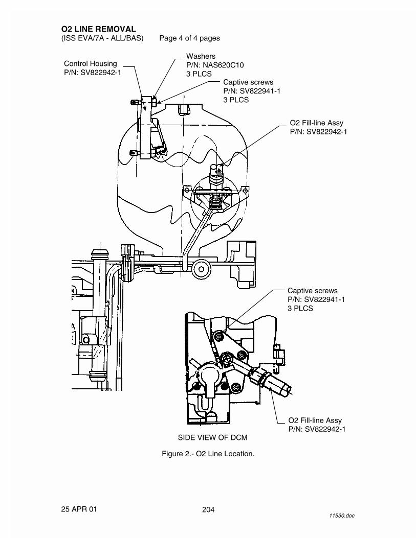
O2 LINE REMOVAL (ISS EVA/7A - ALL/BAS) Page 4 of 4 pages
25 APR 01 11530.doc
O2 Fill-line Assy P/N: SV822942-1
Control Housing P/N: SV822942-1
Washers P/N: NAS620C10 3 PLCS
Captive screws P/N: SV822941-1 3 PLCS
O2 Fill-line Assy P/N: SV822942-1
Captive screws P/N: SV822941-1 3 PLCS
SIDE VIEW OF DCM
Figure 2.- O2 Line Location.
204
O2 ACTUATOR REMOVAL (ISS EVA/7A - ALL/BAS) Page 1 of 3 pages
23 APR 01 11527.doc
DCM 1. �TCV cover removed
If required, perform the following 2. Unzip the left TMG tunnel. DCM 3. Captive screws (four) using 7/64" Hex Driver (1/4" Drive) and
1/4" Drive Handle to remove TCV cover. Refer to Figures 1 and 2. Secure cover to DCM.
CAUTION
A wrist grounding strap must be donned and connected prior to handling electrical connectors on the EMU. The strap may be removed after connector mate/demate is complete.
4. Don wrist grounding strap.
Wrist grounding strap �|� EDDA DCM 5. P-37 �|� J-37 by pushing the rotary assist tab 6. Apply Kapton tape to connector and receptacle. 7. Doff wrist grounding strap. 8. Captive screws (two) using 7/64" Hex Driver (1/4" Drive) and 1/4"
Torque Limiting Drive to demate O2 actuator from DCM as shown in Figure 1.
PLSS 9. Restrain O2 actuator using Velcro strap on PLSS TMG.
205
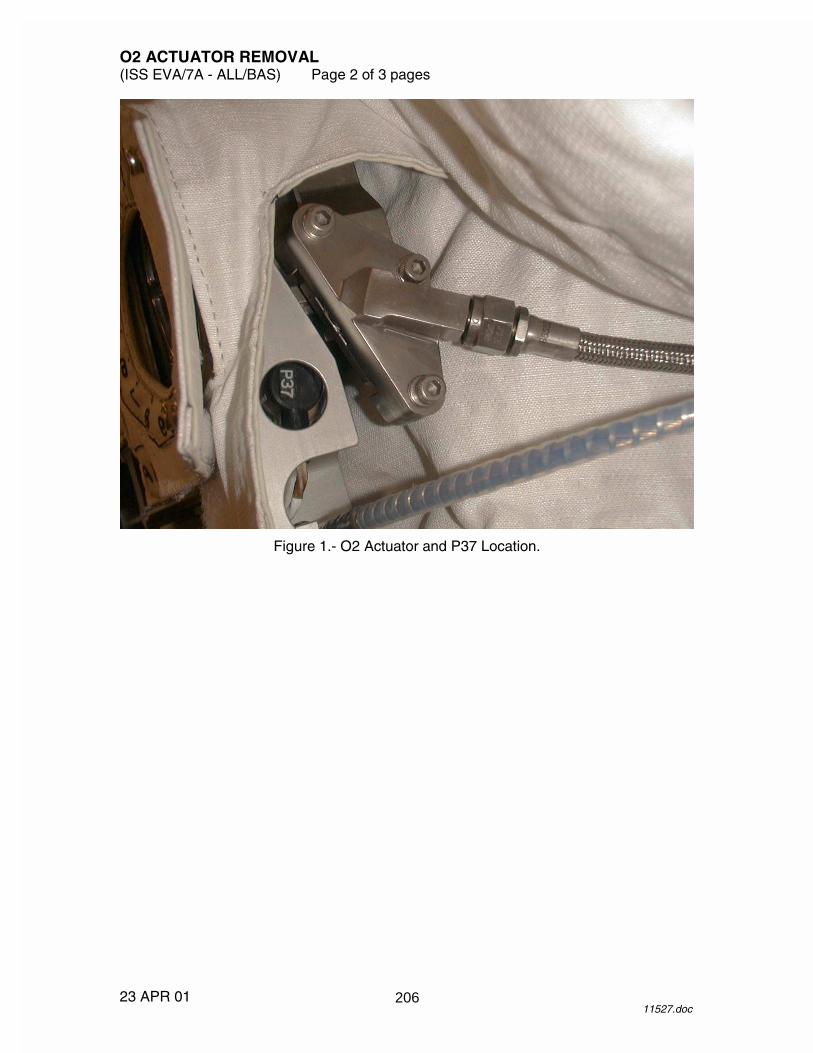
O2 ACTUATOR REMOVAL (ISS EVA/7A - ALL/BAS) Page 2 of 3 pages
23 APR 01 11527.doc
Figure 1.- O2 Actuator and P37 Location.
206

O2 ACTUATOR REMOVAL (ISS EVA/7A - ALL/BAS) Page 3 of 3 pages
23 APR 01 11527.doc
16
5
P-37
J-37
O2 Fill-line Assy P/N: SV822942-1
Captive screws P/N: SV822941-1 3 PLCS
SIDE VIEW OF DCM
P-37 Connector
Captive screws P/N: SV823020-1 2 PLCS
Figure 2.- O2 Actuator and P37 Location.
207

26 APR 01
This Page Intentionally Blank
208
DCM REMOVAL (ISS EVA/7A - ALL/BAS) Page 1 of 3 page
23 APR 01 11523.doc
HUT 1. Unzip the right TMG tunnel.
CAUTION A wrist grounding strap must be donned and connected prior to handling electrical connectors on the EMU. The strap may be removed after connector mate/demate is complete.
2. Don wrist grounding strap.
Wrist grounding strap �|� EDDA
NOTE Do not demate the electrical connectors at the DCM.
PLSS 3. Electrical connectors (two) �|� PLSS connector bracket 4. Cover electrical connectors, receptacles with Kapton tape. 5. Doff wrist grounding strap. DCM 6. COMM mode � PRI 7. Captive screws (two) from the upper and lower DCM mounts using
5/32" Ballnose Driver (5") with 3/8" Ratchet. HUT 8. Remove front tube shield from inside HUT at the HUT/DCM interface pad
by demating Velcro. 9. Disengage slide-locks (two) on DCM installation screws. 10. DCM mounting screws (four) using 3/16" Hex Driver, 4" Ext, and
3/8" Ratchet. DCM 11. �Screws completely backed out 12. Carefully separate DCM from HUT. 13. Inspect HUT/DCM interface pad for water.
If water present, dry with lint free wipes. HUT 14. Reinstall tube shield inside HUT. DCM 15. Record serial number of removed DCM.
Log DCM information in IMS. 16. Mark and temporarily stow removed DCM.
209

DCM REMOVAL (ISS EVA/7A - ALL/BAS) Page 2 of 3 page
23 APR 01 11523.doc
9
3
4 5
26
7 83 PLACES
2 PLACES
Figure 1.- HUT Upper and Lower DCM Mounts.
210
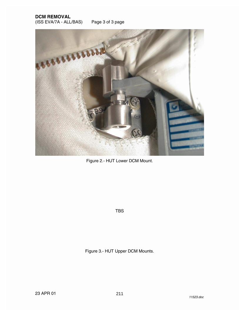
DCM REMOVAL (ISS EVA/7A - ALL/BAS) Page 3 of 3 page
23 APR 01 11523.doc
Figure 2.- HUT Lower DCM Mount.
TBS
Figure 3.- HUT Upper DCM Mounts.
211

26 APR 01
This Page Intentionally Blank
212

HUT/PLSS DISCONNECTION (ISS EVA/7A - ALL/BAS) Page 1 of 2 pages
20 APR 01 11525.doc
HUT 1. Unzip the right HUT TMG tunnel.
CAUTION A wrist grounding strap must be donned and connected prior to handling electrical connectors on the EMU. The strap may be removed after connector mate/demate is complete.
2. Don wrist grounding strap.
Wrist grounding strap �|� EDDA
NOTE Do not demate the electrical connectors at the DCM.
PLSS 3. �Electrical connectors (two) �|� PLSS connector bracket
If required, perform the following 4. Don wrist grounding strap.
Wrist grounding strap �|� EDDA
NOTE Do not demate the electrical connectors at the DCM.
PLSS 5. Electrical connectors (two) �|� PLSS connector bracket 6. Cover electrical connectors, receptacles with Kapton tape. 7. Close the right HUT TMG tunnel. HUT 8. On upper left shoulder of HUT, P10 �|� J10 by pushing the rotary assist
tab Restrain P10 to PLSS TMG.
9. Unzip left TMG tunnel. 10. In the left TMG tunnel, remove power harness connector from covering,
P5 �|� J5 11. Doff wrist grounding strap. 12. Remove upper tube shield from inside HUT at the HUT/PLSS interface
pad. 13. Disengage slide-locks (two) on the HUT/PLSS interface pad. 14. Mounting screws (four) using 1/4" Ballnose Hex Driver (3/8" Drive) with
3/8" Universal Drive, 4" Ext, and 3/8" Ratchet. Refer to Figure 1.
213

HUT/PLSS DISCONNECTION (ISS EVA/7A - ALL/BAS) Page 2 of 2 pages
20 APR 01 11525.doc
PLSS 15. TMG tunnels �|� PLSS interface 16. �No items are restraining the HUT to the PLSS HUT 17. Tip HUT forward to clear alignment pin; carefully lift and separate the
HUT from the PLSS. 18. Inspect HUT/PLSS interface pad for water.
If water present, dry with lint free wipes. 19. Cover PLSS interface with bagging; secure with Kapton tape. 20. Reinstall tube shield inside HUT. 21. Record serial number of removed HUT/PLSS.
Log HUT/PLSS information in IMS. 22. Mark and temporarily stow removed HUT/PLSS.
Figure 1.- HUT/PLSS Interface Captive Screws (with Tube Shield).
214

HUT/PLSS CONNECTION (ISS EVA/7A - ALL/BAS) Page 1 of 3 pages
23 APR 01 11524.doc
HUT 1. Record serial number of replacement HUT/PLSS. 2. If required, install replacement PLSS in EDDA. PLSS 3. Inspect PLSS interface plate for water.
If water present, dry with lint free wipes. 4. �PLSS interface plate free of corrosion, nicks, cuts, abrasions, flat spots
Verify all O-seals are present with no damage. HUT 5. �HUT is free of unrestrained items PLSS 6. �TMG is not blocking PLSS interfaces HUT 7. Remove rear tube shield from inside HUT at the HUT/PLSS interface pad. 8. �HUT/PLSS interface pad free of debris, damage, or restricted
passageways 9. �Captive screws (four) are backed out
CAUTION If there is any interference during mating of HUT to PLSS, stop until interference can be resolved. Avoid kinking of the O2 line and actuator cable during HUT installation.
NOTE
Steps 10 and 11 are performed simultaneously. 10. Carefully position the replacement HUT above the PLSS interface plate. 11. Lower HUT onto PLSS, engaging HUT lower mounts (trailer hitches) on
PLSS mounting bolts.
�Alignment pin on HUT interface pad aligns with PLSS interface plate �HUT lower mounts engaged by pulling HUT forward
CAUTION
For torque operations, use straight shafted hex drivers only. Do not use Ballnose type drivers on inside of HUT.
HUT 12. Hand tighten captive screws (four) in cross pattern. 13. Torque HUT captive screws (four) in cross pattern to 160 in-lbs using
1/4" Hex Driver (3/8" Drive), 3/8" Universal Drive, 4" Ext, and 3/8" Torque Wrench.
14. Engage slide-locks (two).
215

HUT/PLSS CONNECTION (ISS EVA/7A - ALL/BAS) Page 2 of 3 pages
23 APR 01 11524.doc
15. Reinstall tube shield inside HUT.
CAUTION A wrist grounding strap must be donned and connected prior to handling electrical connectors on the EMU. The strap may be removed after connector mate/demate is complete.
16. Don wrist grounding strap.
Wrist grounding strap �|� EDDA HUT 17. Near neck ring on upper left shoulder, P10 �|� J10 using alignment
marks
If DCM already installed HUT 18. Unzip left HUT TMG tunnel.
Route O2 line, O2 actuator, and power harness connector through the tunnel for proper positioning.
19. In the left TMG tunnel, P5 �|� J5, install in cover
Close TMG tunnel. PLSS 20. Electrical connectors (two) on DCM �|� PLSS connector bracket
(yellow-to-yellow, blue-to-blue) 21. Unzip right TMG tunnel.
Route electrical connectors through the tunnel for proper positioning. Close TMG tunnel.
22. Doff wrist grounding strap.
216

HUT/PLSS CONNECTION (ISS EVA/7A - ALL/BAS) Page 3 of 3 pages
23 APR 01 11524.doc
Figure 1.- HUT/PLSS Interface Captive Screws (with Tube Shield).
217

26 APR 01
This Page Intentionally Blank
218
DCM INSTALLATION (ISS EVA/7A - ALL/BAS) Page 1 of 4 pages
23 APR 01 11522.doc
DCM 1. Record serial number of replacement DCM. HUT 2. Remove front tube shield from interior of HUT. 3. �Bagging, Kapton tape removed from interface plate DCM/ 4. Inspect HUT/DCM interface plate for water. HUT If water present, dry with lint free wipes. 5. �HUT/DCM interface pad free of corrosion, nicks, cuts, abrasions, flat
spots, and presence of all O-seals HUT 6. Run the adjustable nut on HUT upper DCM mount flush with boss on
HUT using hands; do not tighten. Refer to Figures 1 and 2.
7. Run the adjustable nut on HUT lower DCM mount flush with boss on
HUT using hands; do not tighten. 8. �Captive screws (four) are backed out at HUT/DCM interface pad
CAUTION If there is any interference during the mating of the DCM to HUT, stop until interference can be resolved.
9. Ensure adequate clearance around the DCM upper mount. DCM 10. �TMG is not blocking HUT/DCM interfaces 11. �Upper/lower mounts are backed out 12. Carefully align DCM to HUT. HUT 13. Hand tighten HUT captive screws (four) in cross pattern.
�HUT interface pad and DCM interface plate aligned and flat 14. Install captive fastener in upper DCM mounting bracket, 2-3 turns. 15. Install captive fastener in lower DCM mounting bracket, 2-3 turns. 16. Torque HUT captive screws (four) in cross pattern to 75 --- 80 in-lbs using
3/16" Hex Driver (3/8" Drive), 4" Ext, and 3/8" Torque Wrench. 17. Engage slide-locks (two). 18. Reinstall front tube shield to interior of HUT at HUT/DCM interface pad by
mating Velcro.
219

DCM INSTALLATION (ISS EVA/7A - ALL/BAS) Page 2 of 4 pages
23 APR 01 11522.doc
19. Back out adjustable mounts so they are flush against upper captivation
boss, if required; do not tighten. 20. Hold adjustable mounts (two) in place with 5/16" Open End Wrench.
Tighten captive fasteners on upper and lower mounts to 35 in-lbs using 5/32" Ballnose Hex Driver (5"), 4" Ext, 3/8" Torque Wrench.
CAUTION A wrist grounding strap must be donned and connected prior to handling electrical connectors on the EMU. The strap may be removed after connector mate/demate is complete.
21. Don wrist grounding strap.
Wrist grounding strap �|� EDDA 22. Remove Kapton tape from electrical connectors. PLSS 23. Electrical connectors (two) on DCM �|� PLSS connector bracket
(yellow-to-yellow, blue-to-blue) 24. Doff wrist grounding strap. 25. Route electrical connectors through the tunnel for proper positioning.
Close TMG tunnel.
220

DCM INSTALLATION (ISS EVA/7A - ALL/BAS) Page 3 of 4 pages
23 APR 01 11522.doc
9
3
4 5
26
7 83 PLACES
2 PLACES
Figure 1.- HUT Upper and Lower DCM Mounts.
221

DCM INSTALLATION (ISS EVA/7A - ALL/BAS) Page 4 of 4 pages
23 APR 01 11522.doc
Figure 2.- Upper and Lower DCM Mounts.
222

O2 ACTUATOR INSTALLATION (ISS EVA/7A - ALL/BAS) Page 1 of 3 pages
23 APR 01 11526.doc
DCM 1. �TCV cover removed
If required, perform the following 2. Unzip the left TMG tunnel. DCM 3. Captive screws (four) using 7/64" Hex Driver (1/4" Drive) and
1/4" Drive Handle to remove TCV cover. Refer to Figures 1 and 2. Secure cover to DCM.
4. Unstow O2 actuator. 5. Install O2 actuator on DCM by aligning the slot with the tab on the
alignment bracket as shown in Figure 1. 6. Captive screws (two) using 7/64" Hex Driver and 1/4" Torque limiting
drive, torque 9-10 in-lbs.
CAUTION A wrist grounding strap must be donned and connected prior to handling electrical connectors on the EMU. The strap may be removed after connector mate/demate is complete.
7. Don wrist grounding strap.
Wrist grounding strap �|� EDDA 8. Remove Kapton tape from P-37. 9. On left side of DCM housing, P-37 �|� J37 using alignment marks;
rotary assist tab . 10. Doff wrist grounding strap. 11. Unstow and install TCV cover. 12. Torque captive screws (four) in cross pattern to 9-10 in-lbs using
7/64" Hex Driver (1/4" Drive), 1/4" Torque Limiting Drive. 13. Route O2 actuator through the tunnel.
Close TMG tunnel.
223

O2 ACTUATOR INSTALLATION (ISS EVA/7A - ALL/BAS) Page 2 of 3 pages
23 APR 01 11526.doc
16
5
P-37
J-37
O2 Fill-line Assy P/N: SV822942-1
Captive screws P/N: SV822941-1 3 PLCS
SIDE VIEW OF DCM
P-37 Connector
Captive screws P/N: SV823020-1 2 PLCS
Figure 1.- O2 Actuator and P37 Location.
224

O2 ACTUATOR INSTALLATION (ISS EVA/7A - ALL/BAS) Page 3 of 3 pages
23 APR 01 11526.doc
Figure 2.- TCV Cover.
225

26 APR 01
This Page Intentionally Blank
226

O2 LINE INSTALLATION (ISS EVA/7A - ALL/BAS) Page 1 of 3 pages
23 APR 01 11528.doc
PLSS 1. Unstow O2 line. 2. Remove the Kapton tape from the O2 line. 3. Inspect O2 line for debris or damage that could preclude installation.
Inspect DCM O-seal and backup rings. DCM 4. �TCV cover removed
If required, perform the following 5. Unzip the left TMG tunnel. DCM 6. Captive screws (four) using 7/64" Hex Driver (1/4" Drive) and
1/4" Drive Handle to remove TCV cover. Refer to Figures 1 and 2 for screw location. Secure cover to DCM.
7. Peel back TMG to access left side of DCM.
CAUTION Maintain alignment of O2 line during installation to avoid damage to the bore and avoid contact with “O2 wetted” surfaces.
8. Install O2 line onto DCM mounting plate.
Hand tighten captive screws (three). 9. Torque captive screws (three) to 35 in-lbs using 5/32" Ballnose Hex
Driver (5"), 3/8" Ratchet, 1/4" to 3/8" Adapter, and 1/4" Torque Limiting Drive to get 35 in-lbs.
10. Route O2 line through the tunnel.
Close TMG tunnel.
227

O2 LINE INSTALLATION (ISS EVA/7A - ALL/BAS) Page 2 of 3 pages
23 APR 01 11528.doc
TCV Handle Guard P/N: SV822933-1
Captive Screw P/N: SV823020-2 4 PLCS
Figure 1.- TCV Cover Location.
228
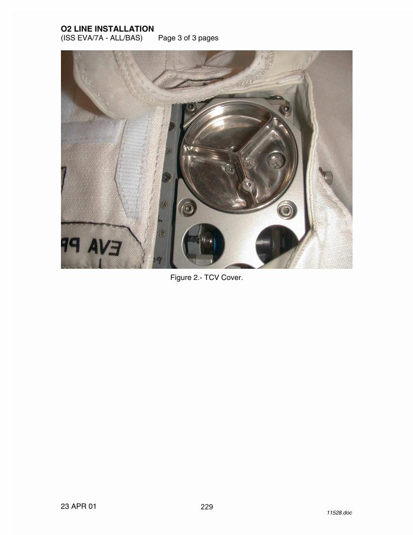
O2 LINE INSTALLATION (ISS EVA/7A - ALL/BAS) Page 3 of 3 pages
23 APR 01 11528.doc
Figure 2.- TCV Cover.
229

26 APR 01
This Page Intentionally Blank
230

����������
���� ������������
��
��
���
��
��
�
��
��
�
�
�
231

����������
�
������������������������������
��
��
���
��
��
�
��
��
�
�
�
232

������������� �����
������������������� � ������������������
�������������������
��������� �!���!�"#���$#���%���!&��'� $'��(�')�'!$�'�*"(+++,(-./0�1&����!&���$��!�*++/�$��!&��#��!�!1��-$�$!�����!&���23����$�#�'% "����'-�!&��*+/�$��!&��)���$�'�'% "������!&������ �!�����"#�,�
�� �,� ���$�4�!&�!�'�1����� �!���!�"#���$#���&�)��"��'�(��$�-�!��!&����2�$'�!&��
�� ��-$��(!��4����������,�+�,��
�2�� �,��3������5����1����%� ����66��
7��� �,���5�����0���1��!1� ����66�
��5�����0����8�����%� ��� ��
���� �,���37�3�8���37��0���1��!1� ����5���
������29������������!&��"�!!��4�(&������"�$'��(�''�(!�-��������� �!���!�"#��%�-�!�,�
�
�29� �,� 3������5����1������
�3������5�����8��� ��
5�$!������(�'-��%'!$#��$9�#�!��!�$��(� �#�!�,�
� .,��8$��#�4����-�"#���'-�2:��;��(�#% '����-�<� 2:<���� � �<���� � �<���
� =,� 3�8���1���������
� ,� 8�����1���:�����>��
���-$��#�4����"#�-�"#�'?����@���?��!A��'��'4�-$��#�4�
� B,� 3������5����1��!1� ����66��� C,� �����!��!�������,���29� ��,� �� �)���� �!�����!�(�)���1$!&���8��(��1-�$)��,��
� ��,� �2��!����2��� �!�����!�(�"#���D���29��� �!�����!�(�''�(!����
��2� ��,� �2��!����2��� �!�����!�(�"#���D����8�(� ����!��
�29� ��,� 3�8���1���������
� ��,� 8�����1�����3������'��!$ � ��
� �.,� ���$�4�-$��#�4���@�� ����A����2� �=,� ��#�(!���8����#$(�!$�'��$(�'��'���2�5$'-�1��-��?!��,��
233

������������� �����
������������������� � ������������������
�������������������
� �,� ��#�(!���8��2����#$(�!$�'�$(�'��������,�+� ,��� �B,� 7���!&������1�?�4�!����#�(!�&$�&#$�&!�2��6�;7������,�
�������'!��,��� �C,� 7���!&������1�?�4�!����#�(!�!4��<�2���������:,�
���$�4����!<��2�3�����$�4��--�<����6B����$�4�$'!<���������E%$��-0�%���!&��!�"��'-�����1�?�4��!��(&�'������!0��--�0��'-�$'!���!!$'���!��!&�������($�$�-,�
�� ��,� �������'!��,��� ��,� 7���!&������1�?�4�!����#�(!�&$�&#$�&!�7��8�5�����8��;,�
�������'!��,��� ��,� 7�������1�?�4��!����#�(!�&$�&#$�&!�#��-,�
�������'!��,��� ��,� �4���@"(+++A��������� �!����$#�,�
�������'!��,��� ��,� 7���-�1'�����1�?�4�!����#�(!�&$�&#$�&!���'-,�
�������'!��,��� �.,� �'������'���!����'-���$'�F0�%�������1�?�4�!����#�(!�&$�&#$�&!�>��,�
�������'!��,��� �=,� 5�$!��"�%!��.�������(�'-������-�!��!��"����'!��"4!����'-��--�����
$'(�� �'!�������!�#4 0��'-�����-$��#�4�!����!%�'�!�� �'%��(���',��� �,� 7�������1�?�4��!����#�(!�&$�&#$�&!��+��,�
�������'!��,��� �B,� 7���-�1'�����1�?�4�!����#�(!�&$�&#$�&!����7������8��,�
�������'!��,��
�29� �C,� 3�8���1���������
� ��,� 8�����1�����3�����!1��!$ �� ��
� ��,� ���$�4�-$��#�4���@���A����2� ��,� ��#�(!���3���,�+��$(�'��'���2�5$'-�1��-��?!��,��� ��,� 7���!&������1�?�4�!����#�(!���3����2������,�
�������'!��,��� ��,� 7���!&������1�?�4�!����#�(!�2�6�;,�
�������'!��,�
234

������������� �����
������������������� � ������������������
�������������������
� �.,� 7���!&������1�?�4�!����#�(!�!4���2���������:,����$�4����!<��2�3�����$�4��--�<����6B����$�4�$'!<���������E%$��-0�%���!&��!�"��'-�����1�?�4��!��(&�'������!0��--�0��'-�$'!���!!$'���!��!&�������($�$�-,�
�� �=,� �������'!��,��
� �,� ���$�4���2�-$��#�4����-��@����������������������A��1&���0��G�2����$�#��% "����'-��G����$�'�������!1��� ,�
�
� �B,� 3������5����1����66��
�3������5�����8��� ��
� �C,� �2��!����2��� �!��(�"#���D���2��� �!�����!�(�''�(!����� ��,� ��$'�!�##��� �!�����!�(�)���1$!&���8��(��1-�$)��,��� ��,� �����!������������� �$'$'���290������E%$��-,��
235

26 APR 01
This Page Intentionally Blank
236

EMU BATTERY DISCHARGE IN BSA (ISS EVA/7A - ALL/BAS) Page 1 of 4 pages
25 APR 01 10081.doc
1. Install EMU battery(s) to be discharged in BSA, as required. UIA 2. �PWR EV-1,2 sw (two) � OFF
�PWR EV-1,2 LEDs (four) � PSA 3. �EMU MODE EMU 1,2 sw (two) – PWR
�SUIT SELECT sw (two) – OFF �SUIT SELECT LEDs (four) �
NOTE
BC3 and BC4 main power must be applied within 5 seconds of each other to avoid startup error. BC3 and BC4 must both be activated during EMU battery discharge.
BC3,4 4. MAIN POWER sw (two) � ON
�MAIN POWER LEDs (two) �
Wait 20 seconds until pixel test is complete. 5. �Display readable and CHARGE column reads: CH: -
V: ---- A: ----
6. MODE sw (two) � STOP 7. DATA sw (two) � HISTORY
If display garbled/blank or Look At on any display 8. MAIN POWER sw (two) � OFF 9. Repeat steps 4 --- 7. 10. Verify channel profile according to Table 1.
Table 1. Initial BC Channel Profiles BC 3 BC 4
Ch Number
Battery Type Charge History
Ch Number
Battery Type Charge History
CH 4 01EMU BSA No History CH 4 01EMU BSA No History UIA 11. PWR EV-1,2 sw (two) � ON
If no EMU battery installed in BSA EMU 3 slot (refer to BSA SLOT ASSIGNMENTS decal on inside of BSA door)
12. Go to step 33. BC3 13. Remove Remote Port cover with TBD screwdriver. 14. BC Remote Port cable �|� BC3 Remote Port connector SSC 15. BC Remote Port cable �|� TBD com port
237

EMU BATTERY DISCHARGE IN BSA (ISS EVA/7A - ALL/BAS) Page 2 of 4 pages
25 APR 01 10081.doc
BC3 16. MODE sw � STOP 17. DATA sw � REMOTE (two times) 18. �Display ‘PCS MODE’ SSC 19. Select TBD applications icon on SSC Windows desktop. 20. Select TBD BC application icon (REMOTE.EXE). 21. Use the arrow key to select REMOTE CONTROL.
Press Enter. 22. Use the arrow key to select CNFIG.
Press Enter. 23. Use the arrow key to select type CASP 2000/H.
Verify port: COM1 Verify addr: 03F8 Verify int: 4
If required, use the tab and arrow keys to change port, addr, and int settings to those specified.
24. Press Enter. 25. Verify SSC display reads ‘BC05-3 H 5.0 X7 OK’. 26. Use the arrow key to select disch.
Press Enter. 27. Record current GMT ____/____:____:____
Continue discharging EMU battery for 15 minutes.
When 15 minutes has elapsed 28. Use arrow key to select STOP.
Press Enter. Record current GMT ____/____:____:____ Press Esc. Use arrow key to select RETURN TO DOS. Press Enter.
BC3 29. MODE sw � STOP 30. BC Remote Port cable �|� BC Remote Port connector 31. Reinstall Remote Port cover with TBD screwdriver.
238

EMU BATTERY DISCHARGE IN BSA (ISS EVA/7A - ALL/BAS) Page 3 of 4 pages
25 APR 01 10081.doc
If no EMU battery installed in BSA EMU 4 slot (refer to BSA SLOT ASSIGNMENTS decal on inside of BSA door)
32. Go to step 52. BC4 33. Remove Remote Port cover with TBD screwdriver. 34. BC Remote Port cable �|� BC Remote Port connector 35. BC Remote Port cable �|� TBD com port, as required 36. MODE sw � STOP 37. DATA sw � REMOTE (two times) 38. �Display ‘PCS MODE’ SSC 39. Select TBD applications icon on SSC Windows desktop. 40. Select TBD BC application icon (REMOTE.EXE). 41. Use the arrow key to select REMOTE CONTROL.
Press Enter. 42. Use the arrow key to select CNFIG.
Press Enter. 43. Use the arrow key to select type CASP 2000/H.
Verify port: COM1 Verify addr: 03F8 Verify int: 4
If required, use the tab and arrow keys to change port, addr, and int settings to those specified.
44. Press Enter. 45. Verify SSC display reads ‘BC04-3 H 5.0 X7 OK’. 46. Use the arrow key to select disch.
Press Enter. 47. Record current GMT ____/____:____:____
Continue discharging EMU battery for 15 minutes.
When 15 minutes has elapsed 48. Use arrow key to select STOP.
Press Enter. Record current GMT ____/____:____:____ Press Esc. Use arrow key to select RETURN TO DOS. Press Enter.
239

EMU BATTERY DISCHARGE IN BSA (ISS EVA/7A - ALL/BAS) Page 4 of 4 pages
25 APR 01 10081.doc
BC4 49. MODE sw � STOP 50. BC Remote Port cable �|� BC Remote Port connector 51. Reinstall Remote Port cover with TBD screwdriver. SSC 52. BC Remote Port cable �|� TBD com port, stow
If not performing EMU battery recharge BC3,4 53. MAIN POWER sw (two) � OFF
If performing EMU battery recharge 54. Go to {IN-SUIT EMU BATTERY CHARGE INITIATE} (SODF: EVA:
NOMINAL: EMU MAINTENANCE/RECHARGE).
240

EMU BATTERY DISCHARGE IN-SUIT (ISS EVA/7A - ALL/BAS) Page 1 of 5 pages
24 APR 01 10944.doc
1. Install EMU battery(s) to be discharged in EMU(s), as required. E-Lk 2. Unstow BCA to SSC Remote Port cable from SPCE Maintenance Kit.
If SCU not connected to DCM UIA 3. �PWR EV-1,2 sw (two) � OFF
�PWR EV-1,2 LEDs (four) � �EMU O2 SUPPLY PRESS gauge: 850 --- 950
C-Lk wall 4. Remove SCU from stowage straps and pouches.
Transfer SCU to E-Lk. DCM 5. Remove DCM Cover.
Velcro to DCM. 6. SCU ��� DCM
�SCU locked 7. �PWR � SCU PSA 8. �EMU MODE EMU 1,2 sw (two) � PWR
�SUIT SELECT sw (two) � OFF �SUIT SELECT LEDs (four) �
9. MAIN POWER sw � ON
�MAIN POWER LED � 10. EMU MODE EMU 1,2 sw (two) � CHRG
NOTE BC3 and BC4 main power must be applied within 5 seconds of each other to avoid startup error. BC3 and BC4 must both be activated during EMU battery discharge to avoid false ‘batt over-temp error’ message.
BC3,4 11. MAIN POWER sw (two) � ON
�MAIN POWER LEDs (two) � 12. Wait 20 seconds until pixel test is complete.
�Display readable and CHARGE column reads: CH: - V: ---- A: ----
13. MODE sw (two) � STOP 14. DATA sw (two) � HISTORY
241

EMU BATTERY DISCHARGE IN-SUIT (ISS EVA/7A - ALL/BAS) Page 2 of 5 pages
24 APR 01 10944.doc
If display garbled/blank or ‘Look At’ on any display 15. On BC3 and BC4, MAIN POWER sw (two) � OFF 16. Repeat steps 11 --- 14. 17. Verify channel profile according to Table 1 by toggling
DATA sw � HISTORY
Table 1. Initial BC Channel Profiles BC 3 BC 4
Ch Number
Battery Type Charge History
Ch Number
Battery Type Charge History
CH 1 02EMU SUIT No History CH 1 02EMU SUIT No History
UIA 18. PWR EV-1,2 sw (two) � ON
If no EMU battery to be discharged in EMU1 (BC4) 19. Go to step 42. BC4 20. Remove Remote Port cover with TBD screwdriver. 21. BCA to SSC Remote Port cable ��� REMOTE PORT SSC 22. BCA to SSC Remote Port cable ��� COM1 port BC4 23. MODE sw � STOP 24. DATA sw � REMOTE (two times) 25. Verify display � ‘PCS’ mode. SSC 26. Select TBD applications icon on SSC Windows desktop. 27. Select TBD BC application icon (REMOTE.EXE). 28. Use arrow key to select/highlight REMOTE CONTROL.
Press Enter. 29. Use arrow keys to select/highlight UNIT 1: FUNCTION: CNFIG.
Press Enter. 31. Use the arrow key to select type CASP 2000/H.
Verify port: COM1 Verify addr: 03F8 Verify int: 4
If required, use the Tab and arrow keys to change port, addr, and int settings to those specified.
Press Enter.
242

EMU BATTERY DISCHARGE IN-SUIT (ISS EVA/7A - ALL/BAS) Page 3 of 5 pages
24 APR 01 10944.doc
33. Verify UNIT 1: CASP REMOTE INTERFACE: BC05-3 H 5.0 X7 OK. 34. Use the arrow key to select/highlight UNIT 1: FUNCTION: disch.
Press Enter. 35. Record GMT ____/____:____:____
Continue discharging EMU battery for required time per Table 2 based on Discharge Type.
Table 2. Required Discharge Times
Discharge Type Time (hr:min) High Impedence (0.4 A-hr) 0:16 Battery Conditioning (2.0 A-hr) 1:20 Full Discharge (26.6 A-hr) 17:44
When required time has elapsed
36. Use arrow key to select/highlight UNIT 1: FUNCTION: STOP (do not select/highlight �STOP or �STOP).
Press Enter. Record current GMT ____/____:____:____
37. Press Esc.
Use arrow key to select/highlight RETURN TO DOS. Press Enter.
BC4 38. MODE sw � STOP 39. BC Remote Port cable �|� BC Remote Port connector 40. Reinstall Remote Port cover with TBD screwdriver.
If no EMU battery installed in EMU2 (BC3) 41. Go to step 62. BC3 42. Remove Remote Port cover with TBD screwdriver. 43. BC Remote Port cable ��� BC Remote Port connector 44. BC Remote Port cable ��� TBD com port, as required 45. MODE sw � STOP 46. DATA sw � REMOTE (two times) 47. Verify display � ‘PCS MODE’ SSC 48. Select TBD applications icon on SSC Windows desktop. 49. Select TBD BC application icon (REMOTE.EXE).
243

EMU BATTERY DISCHARGE IN-SUIT (ISS EVA/7A - ALL/BAS) Page 4 of 5 pages
24 APR 01 10944.doc
50. Verify REMOTE CONTROL is highlighted. Use arrow key to highlight REMOTE CONTROL if required.
51. Press Enter. 52. Use arrow keys to select CNFIG.
Press Enter. 53. Use the arrow key to select type CASP 2000/H.
Verify port: COM1 Verify addr: 03F8 Verify int: 4
If required, use the Tab and arrow keys to change port, addr, and int settings to those specified.
54. Press Enter. 55. Verify unit UNIT 1 column SSC display reads ‘BC04-3 H 5.0 X7 OK’.
Table 3. Required Discharge Times Discharge Required Time (hr:min)
High Impedence (0.4 A-hr) 0:16 Batt Conditioning (2.0 A-hr) 1:20 Full Discharge (26.6 A-hr) 17:44
56. Use the arrow keys to select disch.
Press Enter. 57. Record current GMT ____/____:____:____
Continue discharging EMU battery for required time per Table 3.
When TBD minutes has elapsed 58. Use arrow key to select STOP.
Press Enter. Record current GMT ____/____:____:____ Press Esc. Use arrow key to highlight RETURN TO DOS. Press Enter.
BC3 59. MODE sw � STOP 60. BC Remote Port cable �|� BC Remote Port connector 61. Reinstall Remote Port cover with TBD screwdriver. 62. BC Remote Port cable �|� TBD com port and stow
244
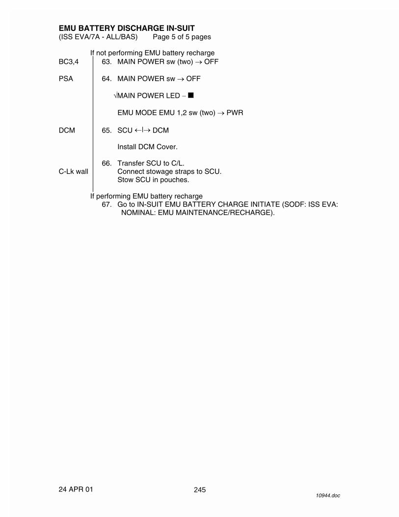
EMU BATTERY DISCHARGE IN-SUIT (ISS EVA/7A - ALL/BAS) Page 5 of 5 pages
24 APR 01 10944.doc
If not performing EMU battery recharge BC3,4 63. MAIN POWER sw (two) � OFF PSA 64. MAIN POWER sw � OFF
�MAIN POWER LED �
EMU MODE EMU 1,2 sw (two) � PWR DCM 65. SCU �|� DCM
Install DCM Cover. 66. Transfer SCU to C/L. C-Lk wall Connect stowage straps to SCU.
Stow SCU in pouches.
If performing EMU battery recharge 67. Go to IN-SUIT EMU BATTERY CHARGE INITIATE (SODF: ISS EVA:
NOMINAL: EMU MAINTENANCE/RECHARGE).
245

26 APR 01
This Page Intentionally Blank
246

BSA FAN SWAP (ISS EVA/7A - ALL/BAS) Page 1 of 1 page
14 FEB 01 9994.doc
NOTE Procedure is written to swap BSA operation from FAN A to FAN B due to a fan failure or BSA door microswitch failure.
NOD1 1. Unstow Phillips Screwdriver #1 from ISS Toolkit, Kit I. BCA 2. �MAIN POWER sw (four) – OFF
�MAIN POWER LEDs (four) – BSA 3. Open BSA door. 4. Unfasten captive screws (four) from BSA fan screen assembly using
Phillips Screwdriver #1. 5. Remove BSA fan screen assembly. 6. BSA fan screen assembly 180� so that FAN B label is upright. 7. Reinstall BSA fan screen assembly. 8. Fasten captive screws (four) on BSA Fan Screen Assembly using Phillips
Screwdriver #1. 9. Swap locations for BSA fan jumper plugs so that plug P5B is mated to the
OPERATIONAL port and P5A is mated to the STOWAGE port. BC1 10. MAIN POWER sw � ON
�MAIN POWER LED – 11. Wait 7 seconds. BSA �Fan operation (nominal noise and flow at BSA fan screen assembly) BC1 12. MAIN POWER sw � OFF
�MAIN POWER LED – BSA 13. Close BSA door. NOD1 14. Stow Phillips Screwdriver #1 in ISS Toolkit, Kit I.
247

26 APR 01
This Page Intentionally Blank
248
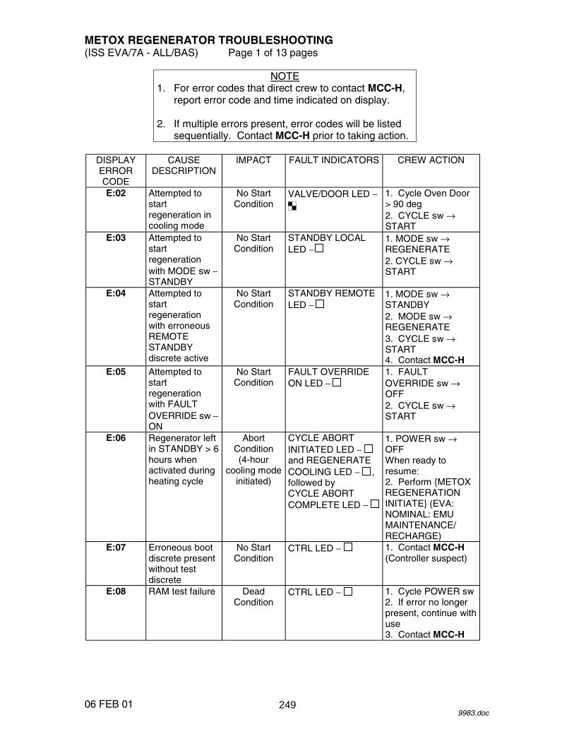
METOX REGENERATOR TROUBLESHOOTING (ISS EVA/7A - ALL/BAS) Page 1 of 13 pages
06 FEB 01 9983.doc
NOTE 1. For error codes that direct crew to contact MCC-H,
report error code and time indicated on display. 2. If multiple errors present, error codes will be listed
sequentially. Contact MCC-H prior to taking action.
DISPLAY ERROR CODE
CAUSE DESCRIPTION
IMPACT FAULT INDICATORS CREW ACTION
E:02 Attempted to start regeneration in cooling mode
No Start Condition
VALVE/DOOR LED −
1. Cycle Oven Door > 90 deg 2. CYCLE sw → START
E:03 Attempted to start regeneration with MODE sw − STANDBY
No Start Condition
STANDBY LOCAL LED −
1. MODE sw → REGENERATE 2. CYCLE sw → START
E:04 Attempted to start regeneration with erroneous REMOTE STANDBY discrete active
No Start Condition
STANDBY REMOTE LED −
1. MODE sw → STANDBY 2. MODE sw → REGENERATE 3. CYCLE sw → START 4. Contact MCC-H
E:05 Attempted to start regeneration with FAULT OVERRIDE sw − ON
No Start Condition
FAULT OVERRIDE ON LED −
1. FAULT OVERRIDE sw → OFF 2. CYCLE sw → START
E:06 Regenerator left in STANDBY > 6 hours when activated during heating cycle
Abort Condition (4-hour
cooling mode initiated)
CYCLE ABORT INITIATED LED − and REGENERATE COOLING LED − , followed by CYCLE ABORT COMPLETE LED −
1. POWER sw → OFF When ready to resume: 2. Perform {METOX REGENERATION INITIATE} (EVA: NOMINAL: EMU MAINTENANCE/ RECHARGE)
E:07 Erroneous boot discrete present without test discrete
No Start Condition
CTRL LED − 1. Contact MCC-H (Controller suspect)
E:08 RAM test failure Dead Condition
CTRL LED − 1. Cycle POWER sw 2. If error no longer present, continue with use 3. Contact MCC-H
249

METOX REGENERATOR TROUBLESHOOTING (ISS EVA/7A - ALL/BAS) Page 2 of 13 pages
06 FEB 01 9983.doc
DISPLAY ERROR CODE
CAUSE DESCRIPTION
IMPACT FAULT INDICATORS CREW ACTION
E:09 ROM test failure Status CTRL LED − 1. Cycle POWER sw 2. If error no longer present, continue with use 3. Contact MCC-H
E:10 Upper Cannister Solenoid Overcurrent (> 2.1 --- 4.4 amps)
Dead Condition
CTRL LED − Contact MCC-H
E:11 Lower Cannister Solenoid Overcurrent (> 2.1 --- 4.4 amps)
Dead Condition
CTRL LED − Contact MCC-H
E:12 Door unlock solenoid overcurrent
Dead Condition
CTRL LED − VALVE/DOOR LED −
Contact MCC-H
E:13 Door lock solenoid overcurrent (> 2.1 --- 4.4 amps)
Dead Condition
CTRL LED − VALVE/DOOR LED −
Contact MCC-H
E:14 Valve solenoid overcurrent (> 2.1 --- 4.4 amps)
Dead Condition
CTRL LED − VALVE/DOOR LED −
Contact MCC-H
E:15 120 V Supply overcurrent (7.0 --- 14.6 amps)
Dead Condition
CTRL LED − Contact MCC-H
E:17 V1 reference is too high (> 6.0 volts)
Dead Condition
CTRL LED − Contact MCC-H
E:18 V2 reference is too high (> 6.0 volts)
No Start Condition
CTRL LED − Contact MCC-H
E:19 V1 reference is too low (< 4.0 volts)
Dead Condition
CTRL LED − Contact MCC-H
E:20 V2 reference is too low (< 4.0 volts)
No Start Condition
CTRL LED − Contact MCC-H
E:21 Zero 1 reference is too high (> 1.0 volts)
Dead Condition
CTRL LED − Contact MCC-H
E:22 Zero 2 reference is too high (> 1.0 volts)
Overridable Condition
CTRL LED − Contact MCC-H
250

METOX REGENERATOR TROUBLESHOOTING (ISS EVA/7A - ALL/BAS) Page 3 of 13 pages
06 FEB 01 9983.doc
DISPLAY ERROR CODE
CAUSE DESCRIPTION
IMPACT FAULT INDICATORS CREW ACTION
E:23 Zero 1 reference is too low (< -1.0 volts)
Dead Condition
CTRL LED − Contact MCC-H
E:24 Zero 2 reference is too low (< -1.0 volts)
Overridable Condition
CTRL LED − Contact MCC-H
E:25 +12 V too high (> 14.0 volts)
Abort Condition (4-hour
cooling mode initiated)
CTRL LED − with: CYCLE ABORT INITIATED LED − and REGENERATE COOLING LED − , followed by CYCLE ABORT COMPLETE LED −
Contact MCC-H
E:26 -12 V too high (> -10.0 volts)
Abort Condition (4-hour
cooling mode initiated)
CTRL LED − with: CYCLE ABORT INITIATED LED − and REGENERATE COOLING LED − , followed by CYCLE ABORT COMPLETE LED −
Contact MCC-H
E:27 +12 V too low (< 10.0 volts)
Abort Condition (4-hour
cooling mode initiated)
CTRL LED − with: CYCLE ABORT INITIATED LED − and REGENERATE COOLING LED − , followed by CYCLE ABORT COMPLETE LED −
Contact MCC-H
E:28 -12 V too low (< -14.0 volts)
Abort Condition (4-hour
cooling mode initiated)
CTRL LED − with: CYCLE ABORT INITIATED LED − and REGENERATE COOLING LED − , followed by CYCLE ABORT COMPLETE LED −
Contact MCC-H
E:29 Upper Canister Indicator Solenoid voltage high (Solenoid feedback indicates it is on prior to completion of regeneration.
Dead Condition
CTRL LED − Contact MCC-H (Controller suspect)
251

METOX REGENERATOR TROUBLESHOOTING (ISS EVA/7A - ALL/BAS) Page 4 of 13 pages
06 FEB 01 9983.doc
DISPLAY ERROR CODE
CAUSE DESCRIPTION
IMPACT FAULT INDICATORS CREW ACTION
E:30 Upper Canister Indicator Solenoid voltage low (Solenoid commanded on, but feedback indicates off)
Status Conditon
CTRL LED − If no other errors present, no action. When regeneration complete, canister state indicator will require manual actuation to the R position
E:31 Lower Canister Indicator Solenoid voltage high (Solenoid feedback indicates it is on prior to completion of regeneration)
Dead Condition
CTRL LED − Contact MCC-H (Controller suspect)
E:32 Lower Canister Indicator Solenoid voltage low (Solenoid commanded on, but feedback indicates off)
Status Condition
CTRL LED − If no other errors present, no action. When regeneration complete, canister state indicator will require manual actuation to the R position
E:33 Watchdog never ready
Abort Condition (4-hour
cooling mode initiated)
CTRL LED − with: CYCLE ABORT INITIATED LED − and REGENERATE COOLING LED − , followed by CYCLE ABORT COMPLETE LED −
Contact MCC-H
E:34 Watchdog reset too wide
Abort Condition (4-hour
cooling mode initiated)
CTRL LED − with: CYCLE ABORT INITIATED LED − and REGENERATE COOLING LED − , followed by CYCLE ABORT COMPLETE LED −
Contact MCC-H
E:35 Fan RPM < 30,000 (15 seconds after start)
Dead Condition
CTRL LED − FAN LED−
1. Cycle POWER sw 2. If error no longer present, continue with use 3. Contact MCC-H
252

METOX REGENERATOR TROUBLESHOOTING (ISS EVA/7A - ALL/BAS) Page 5 of 13 pages
06 FEB 01 9983.doc
DISPLAY ERROR CODE
CAUSE DESCRIPTION
IMPACT FAULT INDICATORS CREW ACTION
E:36 Fan RPM > 30,000 < 40,000 (for 60 seconds)
Overridable Condition
CTRL LED − FAN LED−
1. Cycle POWER sw 2. If error no longer present, continue with use 3. Contact MCC-H
E:37 Fan RPM > 60,000 (15 seconds after start)
Dead Condition
CTRL LED − FAN LED−
1. Cycle POWER sw 2. If error no longer present, continue with use 3. Contact MCC-H
E:38 Fan > 60000 RPM (for 60 seconds)
Overridable Condition
CTRL LED − FAN LED−
1. Cycle POWER sw 2. If error no longer present, continue with use 3. Contact MCC-H
E:39 Fan did not turn off when commanded
Abort Condition (4-hour
cooling mode initiated)
CTRL LED − and FAN LED− with: CYCLE ABORT INITIATED LED − and REGENERATE COOLING LED − , followed by CYCLE ABORT COMPLETE LED −
Contact MCC-H
E:40 Heater Overcurrent (> 6.2 --- 12.8 amps)
Abort Condition (4-hour
cooling mode initiated)
CYCLE ABORT INITIATED LED − and REGENERATE COOLING LED − , followed by CYCLE ABORT COMPLETE LED −
Contact MCC-H
E:41 Heater Undervoltage when on (< 94.5)
Abort Condition (4-hour
cooling mode initiated)
CTRL LED − and HEATER LED − with: CYCLE ABORT INITIATED LED − and REGENERATE COOLING LED − , followed by CYCLE ABORT COMPLETE LED −
Contact MCC-H
E:42 Heater Overvoltage when off (> 25 volts with Server On) (> 10 volts with Server Off)
Dead Condition
CTRL LED − and HEATER LED − with: CYCLE ABORT INITIATED LED − and REGENERATE COOLING LED − , followed by CYCLE ABORT COMPLETE LED −
Contact MCC-H
253

METOX REGENERATOR TROUBLESHOOTING (ISS EVA/7A - ALL/BAS) Page 6 of 13 pages
06 FEB 01 9983.doc
DISPLAY ERROR CODE
CAUSE DESCRIPTION
IMPACT FAULT INDICATORS CREW ACTION
E:43 Heater on after power server is Off (> 25 volts with Server On) (> 10 volts with Server Off)
Abort Condition (4-hour
cooling mode initiated)
CTRL LED − and HEATER LED − with: CYCLE ABORT INITIATED LED − and REGENERATE COOLING LED − , followed by CYCLE ABORT COMPLETE LED −
Contact MCC-H If no comm with MCC-H, POWER sw → OFF
E:44 Heater too slow (failed to bring temp up to set value after standby mode within 6 hours)
Overridable Condition
HEATER LED − Contact MCC-H
E:45 Door not indicating latched while regenerating
Overridable Condition
VALVE/DOOR LED − 1. ����� ��� �����and latched 2. FAULT OVERRIDE sw → ON, � ���� ��������
ON LED − 3. Contact MCC-H
E:46 Diverter Valve not in Cooling position when commanded
Overridable Condition
VALVE/DOOR LED − Contact MCC-H
E:47 Diverter Valve not in Heating position when commanded
Overridable Condition
VALVE/DOOR LED − Contact MCC-H
E:48 Diverter Valve position not at Limit default
Overridable Condition
VALVE/DOOR LED − Contact MCC-H
E:49 Diverter Valve indicates both Heating and Cooling position
Overridable Condition
VALVE/DOOR LED − Contact MCC-H
E:50 Internal Heater Temp Sensor Invalid Low (T1 < -30° F)
Overridable Condition
CTRL LED − HEATER LED −
1. FAULT OVERRIDE sw → ON, � ���� ��������
ON LED − 2. Contact MCC-H
E:51 Internal Heater Temp Sensor Invalid Low (T2 < -30° F)
Overridable Condition
CTRL LED − HEATER LED −
1. FAULT OVERRIDE sw → ON, � ���� ��������
ON LED − 2. Contact MCC-H
254

METOX REGENERATOR TROUBLESHOOTING (ISS EVA/7A - ALL/BAS) Page 7 of 13 pages
06 FEB 01 9983.doc
DISPLAY ERROR CODE
CAUSE DESCRIPTION
IMPACT FAULT INDICATORS CREW ACTION
E:52 Internal Heater Temp Sensor Invalid High (T1 > 600° F)
Overridable Condition
CTRL LED − HEATER LED −
1. FAULT OVERRIDE sw → ON, � ���� ��������
ON LED − 2. Contact MCC-H
E:53 Internal Heater Temp Sensor Invalid High (T2 > 600° F)
Overridable Condition
CTRL LED − HEATER LED −
1. FAULT OVERRIDE sw → ON, � ���� ��������
ON LED − 2. Contact MCC-H
E:54 Internal Heater Temp Sensors Invalid High (T1 and T2 > 600° F)
Abort Condition (4-hour
cooling mode initiated)
CTRL LED − and HEATER LED − with: CYCLE ABORT INITIATED LED − and REGENERATE COOLING LED − , followed by CYCLE ABORT COMPLETE LED −
Contact MCC-H
E:55 Internal Heater Temp Sensor Overtemp (T1 > 475° F)
Overridable Condition
CTRL LED − HEATER LED −
1. FAULT OVERRIDE sw → ON, � ���� ��ERRIDE ON LED − 2. Contact MCC-H
E:56 Internal Heater Temp Sensor Overtemp (T2 > 475° F)
Overridable Condition
CTRL LED − HEATER LED −
1. FAULT OVERRIDE sw → ON, � ���� ��������
ON LED − 2. Contact MCC-H
E:57 Internal Heater Temp Sensors Overtemp (T1 and T2 > 475° F)
Abort Condition (4-hour
cooling mode initiated)
CTRL LED − and HEATER LED − with: CYCLE ABORT INITIATED LED − and REGENERATE COOLING LED − , followed by CYCLE ABORT COMPLETE LED −
Contact MCC-H
E:58 Internal Heater Temp Sensor Undertemp (T1 < 225° F after 2 hours heating)
Overridable Condition
HEATER LED − 1. FAULT OVERRIDE sw → ON, � ���� ��������
ON LED − 2. Contact MCC-H
255

METOX REGENERATOR TROUBLESHOOTING (ISS EVA/7A - ALL/BAS) Page 8 of 13 pages
06 FEB 01 9983.doc
DISPLAY ERROR CODE
CAUSE DESCRIPTION
IMPACT FAULT INDICATORS CREW ACTION
E:59 Internal Heater Temp Sensor Undertemp (T2 < 225° F after 2 hours heating)
Overridable Condition
HEATER LED − 1. FAULT OVERRIDE sw → ON, � ���� ��������
ON LED − 2. Contact MCC-H
E:60 Internal Heater Temp Sensors Undertemp (T1 and T2 < 225° F after 2 hours heating)
Overridable Condition
HEATER LED − Contact MCC-H
E:61 Internal Heater Temp Sensor Undertemp (T1 < 290° F after 9.5 hours heating)
Overridable Condition
HEATER LED − 1. FAULT OVERRIDE sw → ON, � ���� ��������
ON LED − 2. Contact MCC-H
E:62 Internal Heater Temp Sensor Undertemp (T2 < 290° F after 9.5 hours heating)
Overridable Condition
HEATER LED − 1. FAULT OVERRIDE sw → ON, � ���� ��������
ON LED − 2. Contact MCC-H
E:63 Internal Heater Temp Sensors Undertemp (T1 and T2 < 290° F after 9.5 hours heating)
Overridable Condition
HEATER LED − Contact MCC-H
E:64 Internal Heater Temp Sensor Delta out of range (T1 and T2 differ by > 16° --- 27° F)
Overridable Condition
HEATER LED − 1. FAULT OVERRIDE sw → ON, � ���� ��������
ON LED − 2. Contact MCC-H
E:65 Oven Temp Sensor Invalid Low (T8 < -30° F)
Overridable Condition
CTRL LED − OVEN HOT LED −
1. FAULT OVERRIDE sw → ON, � ���� ��������
ON LED − 2. Contact MCC-H
E:66 Oven Temp Sensor Invalid High (T8 > 440° F)
Overridable Condition
CTRL LED − OVEN HOT LED −
1. FAULT OVERRIDE sw → ON, � ���� ��������
ON LED − 2. Contact MCC-H
256

METOX REGENERATOR TROUBLESHOOTING (ISS EVA/7A - ALL/BAS) Page 9 of 13 pages
06 FEB 01 9983.doc
DISPLAY ERROR CODE
CAUSE DESCRIPTION
IMPACT FAULT INDICATORS CREW ACTION
E:67 Upper and Lower Can Temp Sensors Undertemp (T4 and T6 < 250° F after 4 hours heating, indicating low flow)
Overridable Condition
FLOW LED−
1. ���� �������RECEPTACLE CO2 VALVE − REGEN, 2. ������ ���� �� 3. Contact MCC-H
E:68 Controller Watchdog failed (lost sync)
Abort Condition
CTRL LED − with: CYCLE ABORT INITIATED LED − and REGENERATE COOLING LED − , followed by CYCLE ABORT COMPLETE LED −
Contact MCC-H
E:69 Controller Watchdog failed (out of sync)
Abort Condition
CTRL LED − with: CYCLE ABORT INITIATED LED − and REGENERATE COOLING LED − , followed by CYCLE ABORT COMPLETE LED −
Contact MCC-H
E:70 External Heater Temp Sensor Overtemp (T3 > 525° F)
Abort Condition
CTRL LED − and HEATER LED − with: CYCLE ABORT INITIATED LED − and REGENERATE COOLING LED − , followed by CYCLE ABORT COMPLETE LED −
Contact MCC-H
E:71 External Heater Temp Sensor Invalid Low (T3 < -30° F)
Abort Condition
CTRL LED − and HEATER LED − with: CYCLE ABORT INITIATED LED − and REGENERATE COOLING LED − , followed by CYCLE ABORT COMPLETE LED −
Contact MCC-H
257

METOX REGENERATOR TROUBLESHOOTING (ISS EVA/7A - ALL/BAS) Page 10 of 13 pages
06 FEB 01 9983.doc
DISPLAY ERROR CODE
CAUSE DESCRIPTION
IMPACT FAULT INDICATORS CREW ACTION
E:72 External Heater Temp Sensor Invalid High (T3 > 600° F)
Abort Condition
CTRL LED − and HEATER LED − with: CYCLE ABORT INITIATED LED − and REGENERATE COOLING LED − , followed by CYCLE ABORT COMPLETE LED −
Contact MCC-H
E:73 Upper Canister Outlet Temp Sensor Invalid Low (T4 < -30° F)
Overridable Condition
TEMP LED − 1. FAULT OVERRIDE sw → ON, � ���� ��������
ON LED − 2. Contact MCC-H
E:74 Upper Canister Outlet Temp Sensor Invalid Low (T5 < -30° F)
Overridable Condition
TEMP LED − 1. FAULT OVERRIDE sw → ON, � ���� ��������
ON LED − 2. Contact MCC-H
E:75 Upper Canister Outlet Temp Sensor Invalid High (T4 > 570° F)
Overridable Condition
TEMP LED − 1. FAULT OVERRIDE sw → ON, � ���� ��������
ON LED − 2. Contact MCC-H
E:76 Upper Canister Outlet Temp Sensor Invalid High (T5 > 570° F)
Overridable Condition
TEMP LED − 1. FAULT OVERRIDE sw → ON, � ���� ��������
ON LED − 2. Contact MCC-H
E:77 Upper Canister Outlet Temp Sensors Invalid High (T4 and T5 > 570° F)
Overridable Condition
TEMP LED − Contact MCC-H
E:78 Upper Canister Outlet Temp Sensor Undertemp (T4 < 250° F between 4 --- 10 hours heating)
Status Condition
UPPER CAN LED − Ignore for single canister regeneration. Else, Contact MCC-H
258

METOX REGENERATOR TROUBLESHOOTING (ISS EVA/7A - ALL/BAS) Page 11 of 13 pages
06 FEB 01 9983.doc
DISPLAY ERROR CODE
CAUSE DESCRIPTION
IMPACT FAULT INDICATORS CREW ACTION
E:79 Upper Canister Outlet Temp Sensor Undertemp (T5 < 250° F between 4 --- 10 hours heating)
Status Condition
UPPER CAN LED − Ignore for single canister regeneration. Else, Contact MCC-H
E:80 Upper Canister Outlet Temp Sensors Undertemp (T4 and T5 < 250° F between 4 --- 10 hours heating)
Status Condition
UPPER CAN LED − Ignore for single canister regeneration. Else, Contact MCC-H
E:81 Upper Canister Outlet Temp Sensor no heat spike (T4 < 300° F after 10 hours heating)
Status Condition
UPPER CAN LED − Ignore for single canister regeneration. Else, Contact MCC-H
E:82 Upper Canister Outlet Temp Sensor no heat spike (T5 < 300° F after 10 hours heating)
Status Condition
UPPER CAN LED − Ignore for single canister regeneration. Else, Contact MCC-H
E:83 Upper Canister Outlet Temp Sensors no heat spike (T4 and T5)
Status Condition
UPPER CAN LED − Ignore for single canister regeneration. Else, Contact MCC-H
E:84 Upper Canister too slow (failed to bring temp up to set value after standby mode within 6 hours)
Overridable Condition
UPPER CAN LED − Ignore for single canister regeneration. Else, Contact MCC-H
E:85 Lower Canister Outlet Temp Sensor Invalid Low (T6 < -30° F)
Overridable Condition
TEMP LED − 1. FAULT OVERRIDE sw → ON, � ���� ��������
ON LED − 2. Contact MCC-H
E:86 Lower Canister Outlet Temp Sensor Invalid Low (T7 < -30° F)
Overridable Condition
TEMP LED − 1. FAULT OVERRIDE sw → ON, � ���� ��������
ON LED − 2. Contact MCC-H
259
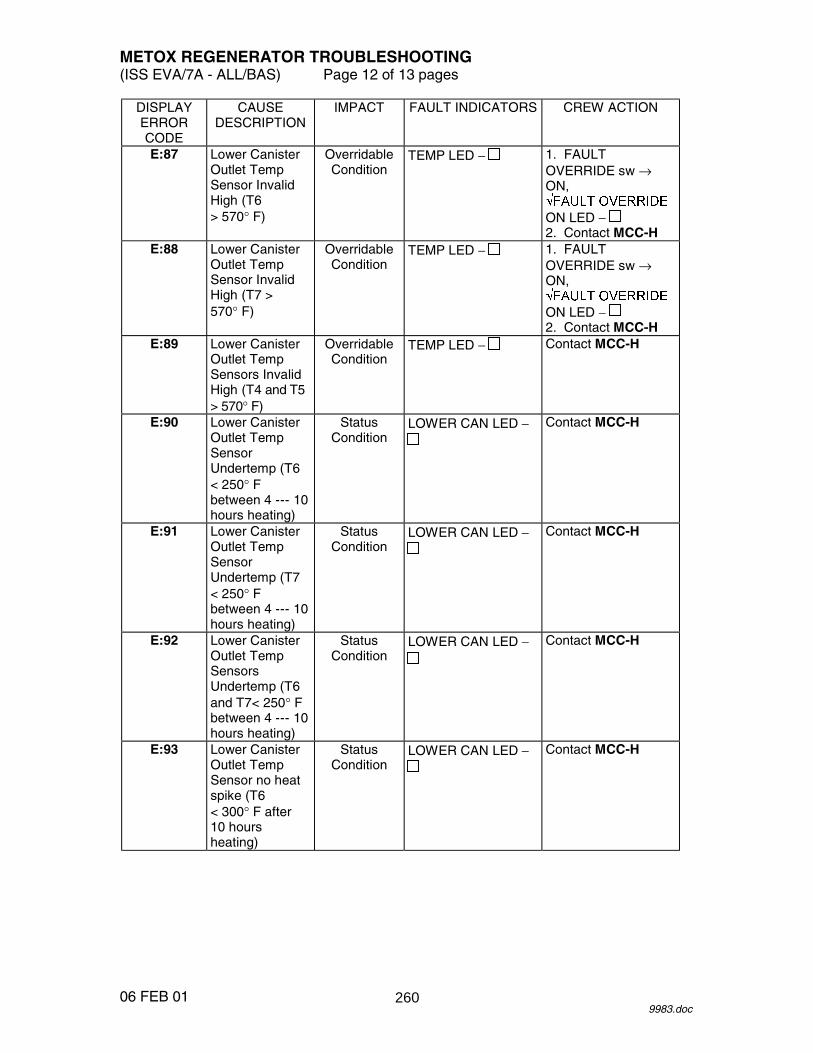
METOX REGENERATOR TROUBLESHOOTING (ISS EVA/7A - ALL/BAS) Page 12 of 13 pages
06 FEB 01 9983.doc
DISPLAY ERROR CODE
CAUSE DESCRIPTION
IMPACT FAULT INDICATORS CREW ACTION
E:87 Lower Canister Outlet Temp Sensor Invalid High (T6 > 570° F)
Overridable Condition
TEMP LED − 1. FAULT OVERRIDE sw → ON, � ���� ��������
ON LED − 2. Contact MCC-H
E:88 Lower Canister Outlet Temp Sensor Invalid High (T7 > 570° F)
Overridable Condition
TEMP LED − 1. FAULT OVERRIDE sw → ON, � ���� ��������
ON LED − 2. Contact MCC-H
E:89 Lower Canister Outlet Temp Sensors Invalid High (T4 and T5 > 570° F)
Overridable Condition
TEMP LED − Contact MCC-H
E:90 Lower Canister Outlet Temp Sensor Undertemp (T6 < 250° F between 4 --- 10 hours heating)
Status Condition
LOWER CAN LED − Contact MCC-H
E:91 Lower Canister Outlet Temp Sensor Undertemp (T7 < 250° F between 4 --- 10 hours heating)
Status Condition
LOWER CAN LED − Contact MCC-H
E:92 Lower Canister Outlet Temp Sensors Undertemp (T6 and T7< 250° F between 4 --- 10 hours heating)
Status Condition
LOWER CAN LED − Contact MCC-H
E:93 Lower Canister Outlet Temp Sensor no heat spike (T6 < 300° F after 10 hours heating)
Status Condition
LOWER CAN LED − Contact MCC-H
260
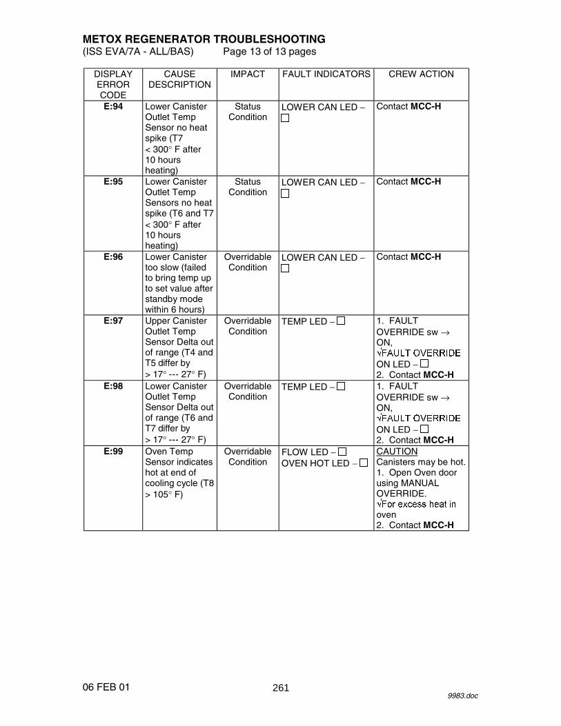
METOX REGENERATOR TROUBLESHOOTING (ISS EVA/7A - ALL/BAS) Page 13 of 13 pages
06 FEB 01 9983.doc
DISPLAY ERROR CODE
CAUSE DESCRIPTION
IMPACT FAULT INDICATORS CREW ACTION
E:94 Lower Canister Outlet Temp Sensor no heat spike (T7 < 300° F after 10 hours heating)
Status Condition
LOWER CAN LED − Contact MCC-H
E:95 Lower Canister Outlet Temp Sensors no heat spike (T6 and T7 < 300° F after 10 hours heating)
Status Condition
LOWER CAN LED − Contact MCC-H
E:96 Lower Canister too slow (failed to bring temp up to set value after standby mode within 6 hours)
Overridable Condition
LOWER CAN LED − Contact MCC-H
E:97 Upper Canister Outlet Temp Sensor Delta out of range (T4 and T5 differ by > 17° --- 27° F)
Overridable Condition
TEMP LED − 1. FAULT OVERRIDE sw → ON, � ���� ��������
ON LED − 2. Contact MCC-H
E:98 Lower Canister Outlet Temp Sensor Delta out of range (T6 and T7 differ by > 17° --- 27° F)
Overridable Condition
TEMP LED − 1. FAULT OVERRIDE sw → ON, � ���� ��������
ON LED − 2. Contact MCC-H
E:99 Oven Temp Sensor indicates hot at end of cooling cycle (T8 > 105° F)
Overridable Condition
FLOW LED − OVEN HOT LED −
CAUTION Canisters may be hot. 1. Open Oven door using MANUAL OVERRIDE. � � ����� ���� ��oven 2. Contact MCC-H
261

26 APR 01
This Page Intentionally Blank
262

HYGIENE BREAK (70 MINUTES) (ISS EVA/7A - ALL/BAS) Page 1 of 2 pages
16 APR 01 11721.doc
MASK PREBREATHE INITIATION EV1,2 A/L1D2 1. PHA �|� PHA port
WARNING Positive mask O2 pressure and fit are necessary to ensure adequate prebreathe.
2. Don mask. PHA 3. Mask O2 control � EMERGENCY mask 4. Momentarily pull mask away from face.
�O2 flow
WARNING Do not terminate prebreathe until airlock pressure is back at 10.2 psia and 70 minutes of hygiene prebreathe completed.
5. Record mask P/B initate time and continue mask prebreathe for
70 minutes.
GMT (MASK P/B INIT: HYGIENE) _____/_____:_____ _____
REPRESSING AIRLOCK TO 14.7 PSI
6. Node 1 Stbd Hatch MPEV � Open 7. MCC-H report equalization time. 8. Open Node 1 Stbd Hatch per decal.
WARNING When dragging PHA hoses thru hatches, ensure QDs are within 3 feet of each hatch.
EV1,2 9. Perform necessary hygiene activities. 10. Retrieve breakfast. 11. Return to airlock.
DEPRESSING AIRLOCK TO 10.2 PSI IV,EV1,EV2 12. Ingress airlock. 13. Close Node 1 Stbd Hatch.
263

HYGIENE BREAK (70 MINUTES) (ISS EVA/7A - ALL/BAS) Page 2 of 2 pages
16 APR 01 11721.doc
14. Actuate hatch to the orange equalize block position indicator on the window frame.
15. Perform {ISS AIRLOCK 10.2 PSIA OPERATIONS INITIATION},
steps 9 --- 11 (SODF: ISS EVA: EMU MAINTENANCE/ RECHARGE), then:
WARNING Do not terminate prebreathe until airlock pressure at 10.2 psia and 70 minutes hygiene prebreathe completed.
When 70 minutes of hygiene prebreathe complete and airlock at 10.2 psi
PHA 16. Mask O2 control � NORMAL mask 17. Doff mask. A/L1D2 18. PHA �|� PHA port
Install cap on PHA port. PHA 19. Stow PHA mask in PHA bag. mask
264

10.2 PSI CAMPOUT EVA PREP (90 MINUTES) (ISS EVA/7A - ALL/BAS) Page 1 of 4 pages
11 APR 01 10001.doc
GMT _____/_____:_____ _____
PREP FOR DONNING (30 MINUTES)
EV1,2 1. Perform {EMU POWERUP}, all (SODF: ISS EVA: EMU MAINTENANCE/RECHARGE), then:
2. Waist ring �|� HUT
Temporarily stow LTA. 3. Helmet �|� HUT
Temporarily stow helmet. 4. Remove dosimeter from inflight garments.
Insert dosimeter in LCVG. 5. Don MAG, TCU, LCVG, biomed.
EV1, 6. Perform {EVA COMM CONFIG}, all (SODF: ISS EVA: EVA MCC-H PREP), then: 7. Biomed �|� electrical harness 8. Don comm cap. DCM 9. COMM mode � PRI 10. �Comm FREQ � LOW 11. Verify biomed, EMU data, RF comm with MCC-H. EV1,2 DCM 12. COMM mode � HL
265

10.2 PSI CAMPOUT EVA PREP (90 MINUTES) (ISS EVA/7A - ALL/BAS) Page 2 of 4 pages
11 APR 01 10001.doc
13. Doff comm cap. 14. Biomed �|� electrical harness ATU4,5 15. PTT pb � Press
1 pb � Press
�Display – ‘1TG’ EACP 16. PWR sw � ON
EMU DONNING (55 MINUTES) NOTE
May be performed by EV1 and EV2 simultaneously. EV1,2 17. Take one aspirin tablet (325 mg), if not taken previously. EV1 DCM 18. �STATUS: SOP P: 5800 --- 6800 (compare with gauge) 19. �Waist ring � op 20. Don LTA (attach donning handles as required). 21. �Suit arms aligned 22. �Wrist disconnects – op 23. Stow IV glasses as required. 24. Don thumb loops. 25. �Biomed connector is outside of HUT 26. Don HUT. 27. Release thumb loops. 28. �Suit arms aligned 29. Don EV glasses as required.
Don comm cap. 30. �Comm 31. Biomed �|� electrical harness 32. LCVG �|� Multiple Water Connector
�Multiple Water Connector locked
266

10.2 PSI CAMPOUT EVA PREP (90 MINUTES) (ISS EVA/7A - ALL/BAS) Page 3 of 4 pages
11 APR 01 10001.doc
33. �Thermal cover clear of waist ring 34. Waist ring � engage position 35. Waist ring �|� HUT
�Waist ring locked 36. Remove donning handles.
Stow donning handles in EMU Equipment Bag. Cover waist ring.
37. �Electrical harness clear of neck ring 38. �Drink vlv position 39. �Mic boom position 40. Don comfort gloves, wristlets. 41. Wrist rings � engage position 42. Don EV gloves.
�EV gloves locked 43. Tighten palm restraint straps. 44. �Glove heater sw (two) – OFF 45. �REBA sw – OFF 46. Lower arm power harness cables �|� Gloves
Stow slack under arm TMG. 47. �Cuff C/L position
CAUTION Rotate vent duct out of C-Lk prior to turning the EMU fan on.
48. Rotate vent duct out of C-Lk.
Attach vent duct to dove tail fitting on hose coupling panel.
CAUTION
Minimize fan operation with O2 ACT � OFF (~2 minutes). DCM 49. FAN � ON
267
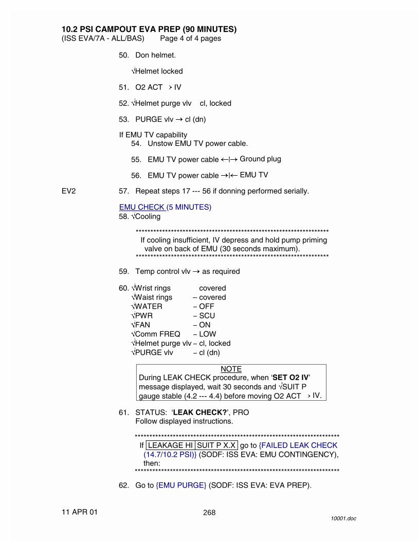
10.2 PSI CAMPOUT EVA PREP (90 MINUTES) (ISS EVA/7A - ALL/BAS) Page 4 of 4 pages
11 APR 01 10001.doc
50. Don helmet.
�Helmet locked 51. O2 ACT � IV 52. �Helmet purge vlv � cl, locked 53. PURGE vlv � cl (dn)
If EMU TV capability 54. Unstow EMU TV power cable. 55. EMU TV power cable �|� Ground plug 56. EMU TV power cable �|� EMU TV EV2 57. Repeat steps 17 --- 56 if donning performed serially.
EMU CHECK (5 MINUTES) 58. �Cooling
****************************************************************** If cooling insufficient, IV depress and hold pump priming valve on back of EMU (30 seconds maximum).
****************************************************************** 59. Temp control vlv � as required 60. �Wrist rings � covered
�Waist rings – covered �WATER � OFF �PWR � SCU �FAN � ON �Comm FREQ � LOW �Helmet purge vlv � cl, locked �PURGE vlv � cl (dn)
NOTE
During LEAK CHECK procedure, when ‘SET O2 IV’ message displayed, wait 30 seconds and �SUIT P gauge stable (4.2 --- 4.4) before moving O2 ACT � IV.
61. STATUS: ‘LEAK CHECK?’, PRO
Follow displayed instructions.
********************************************************************** If LEAKAGE HI SUIT P X.X go to {FAILED LEAK CHECK (14.7/10.2 PSI)} (SODF: ISS EVA: EMU CONTINGENCY), then:
********************************************************************** 62. Go to {EMU PURGE} (SODF: ISS EVA: EVA PREP).
268

EMU CHECKOUT ON PSA POWER (ISS EVA/7A - ALL/BAS) Page 1 of 5 pages
24 FEB 01 10002.doc
NOTE 1. Procedure is written for simultaneous checkout of two EMUs. 2. ‘PWR RESTART’ message occurs and BITE light is illuminated
whenever EMU power is cycled. 3. Perform all DCM PWR switch throws with firm, deliberate action.
1. Helmet �|� HUT 2. Comm cap �|� electrical harness 3. �LTA installed UIA 4. �OXYGEN EMU 1,2 vlv (two) – CLOSE 5. Perform {EMU POWERUP}, all (SODF: ISS EVA: EMU MAINTENANCE/
RECHARGE), then: 6. Perform {COMM CHECK}, all (SODF: ISS EVA: CHECKOUTS), then:
PRIMARY REGULATOR/FAN/PUMP CHECK (20 MINUTES/EMU) DCM 7. �STATUS: O2 P: 850 --- 950
EMU 1 2 3 7. O2 P
UIA 8. �EMU O2 SUPPLY PRESS gauge 850 --- 950 9. OXYGEN EMU 1,2 vlv (two) � OPEN 10. Install helmet, lock. 11. �Suit arms aligned
�Gloves locked �Helmet purge vlv – cl, locked
DCM 12. PURGE vlv � cl (dn) 13. O2 ACT � IV 14. �STATUS: SUIT P: 0.4 --- 1.4 and stable (compare with gauge)
EMU 1 2 3 14. SUIT P (IV)
15. O2 ACT � PRESS
269

EMU CHECKOUT ON PSA POWER (ISS EVA/7A - ALL/BAS) Page 2 of 5 pages
24 FEB 01 10002.doc
16. �STATUS: SUIT P: 4.2 --- 4.4 and stable (compare with gauge) �STATUS: H2O TEMP = ambient �STATUS: H2O GP/WP: 14.0 --- 16.0
EMU 1 2 3
16. SUIT P (PRESS)
H2O TEMP
H2O GP
H2O WP
17. O2 ACT � IV
Start timing manual leak check (2 minutes, SUIT �P � 0.3 psi).
EMU 1 2 3 17. SUIT �P
***************************************************************************
If �P � 0.3 psi, perform {FAILED LEAK CHECK (14.7/10.2 PSI)} (SODF: ISS EVA: EMU CONTINGENCY), then:
*************************************************************************** DCM 18. O2 ACT � OFF 19. PURGE vlv � op (up) 20. �STATUS: SUIT P < 0.4 (compare with gauge) 21. Gloves �|� EMU
Temporarily stow gloves in EMU Equipment Bag. 22. Helmet �|� HUT
Stow helmet. 23. Waist ring �|� HUT
Secure LTA.
If LCVG filled with water 24. LCVG �|� Multiple Water Connector
�Multiple Water Connector locked
270
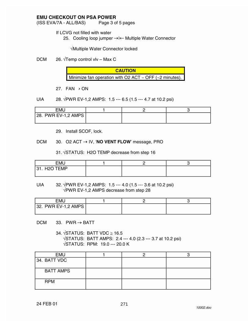
EMU CHECKOUT ON PSA POWER (ISS EVA/7A - ALL/BAS) Page 3 of 5 pages
24 FEB 01 10002.doc
If LCVG not filled with water 25. Cooling loop jumper �|� Multiple Water Connector
�Multiple Water Connector locked DCM 26. �Temp control vlv – Max C
CAUTION
Minimize fan operation with O2 ACT � OFF (~2 minutes). 27. FAN � ON UIA 28. �PWR EV-1,2 AMPS: 1.5 --- 6.5 (1.5 --- 4.7 at 10.2 psi)
EMU 1 2 3 28. PWR EV-1,2 AMPS
29. Install SCOF, lock. DCM 30. O2 ACT � IV, ‘NO VENT FLOW’ message, PRO 31. �STATUS: H2O TEMP decrease from step 16
EMU 1 2 3 31. H2O TEMP
UIA 32. �PWR EV-1,2 AMPS: 1.5 --- 4.0 (1.5 --- 3.6 at 10.2 psi)
�PWR EV-1,2 AMPS decrease from step 28
EMU 1 2 3 32. PWR EV-1,2 AMPS
DCM 33. PWR � BATT 34. �STATUS: BATT VDC � 16.5
�STATUS: BATT AMPS: 2.4 --- 4.0 (2.3 --- 3.7 at 10.2 psi) �STATUS: RPM: 19.0 --- 20.0 K
EMU 1 2 3
34. BATT VDC
BATT AMPS
RPM
271

EMU CHECKOUT ON PSA POWER (ISS EVA/7A - ALL/BAS) Page 4 of 5 pages
24 FEB 01 10002.doc
35. �Fan noise steady 36. O2 ACT � OFF 37. FAN � OFF 38. PWR � SCU
SOP CHECK (2 MINUTES/EMU) DCM 39. �STATUS: SOP P: 5800 --- 6800
Cycle to SUIT P.
EMU 1 2 3 39. SOP P
40. �SOP gauge 5800 --- 6800
Note SOP interstage gauge.
EMU 1 2 3 40. SOP GAUGE
INT GAUGE
41. While depressing SOP manual override (50 seconds maximum)
�SOP interstage gauge < 600 DCM �STATUS: SUIT P: 3.4 --- 3.9 and stable
EMU 1 2 3 41. SUIT P
INT GAUGE
42. Remove SCOF.
Stow SCOF in EMU Equipment Bag. DCM 43. COMM mode � HL UIA 44. PWR EV-1,2 sw (two) � OFF
�PWR EV-1,2 LEDs (four) � 45. LCVG (cooling loop jumper) �|� Multiple Water Connector
Stow LCVG in HUT. 46. Install helmet, LTA.
272

EMU CHECKOUT ON PSA POWER (ISS EVA/7A - ALL/BAS) Page 5 of 5 pages
24 FEB 01 10002.doc
BATTERY CHARGE CHECK INITIATE (10 MINUTES) PSA 47. SUIT SELECT sw (two) � OFF
�SUIT SELECT LEDs (four) � 48. EMU MODE EMU 1,2 sw (two) � CHRG BC3,4 49. Verify CH1 VOLTs > 0. 50. Contact MCC-H to perform {EVA COMM DECONFIG} (SODF: ISS EVA:
CHECKOUTS).
273

26 APR 01
This Page Intentionally Blank
274

����������
���� ������������
���
��
��
�
�
��
�
�
��
��
��
�
275

����������
�
������������������������������
���
��
��
�
�
��
�
�
��
��
��
�
276
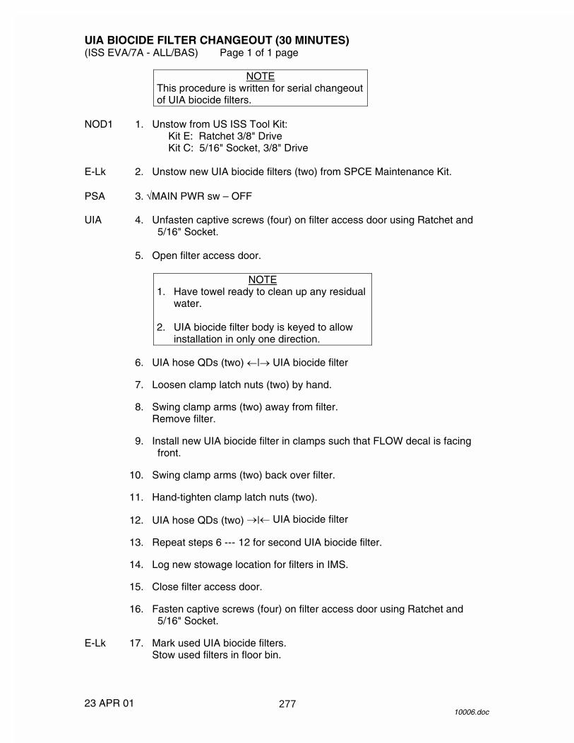
UIA BIOCIDE FILTER CHANGEOUT (30 MINUTES) (ISS EVA/7A - ALL/BAS) Page 1 of 1 page
23 APR 01 10006.doc
NOTE This procedure is written for serial changeout of UIA biocide filters.
NOD1 1. Unstow from US ISS Tool Kit:
Kit E: Ratchet 3/8" Drive Kit C: 5/16" Socket, 3/8" Drive
E-Lk 2. Unstow new UIA biocide filters (two) from SPCE Maintenance Kit. PSA 3. �MAIN PWR sw – OFF UIA 4. Unfasten captive screws (four) on filter access door using Ratchet and
5/16" Socket. 5. Open filter access door.
NOTE 1. Have towel ready to clean up any residual
water. 2. UIA biocide filter body is keyed to allow
installation in only one direction. 6. UIA hose QDs (two) �|� UIA biocide filter 7. Loosen clamp latch nuts (two) by hand. 8. Swing clamp arms (two) away from filter.
Remove filter. 9. Install new UIA biocide filter in clamps such that FLOW decal is facing
front. 10. Swing clamp arms (two) back over filter. 11. Hand-tighten clamp latch nuts (two). 12. UIA hose QDs (two) �|� UIA biocide filter 13. Repeat steps 6 --- 12 for second UIA biocide filter. 14. Log new stowage location for filters in IMS. 15. Close filter access door. 16. Fasten captive screws (four) on filter access door using Ratchet and
5/16" Socket. E-Lk 17. Mark used UIA biocide filters.
Stow used filters in floor bin.
277

26 APR 01
This Page Intentionally Blank
278

SCU INSTALLATION ON UIA (ISS EVA/7A - ALL/BAS) Page 1 of 3 pages
25 APR 01 10007.doc
NOTE Procedure is written for simultaneous installation of two SCUs.
C-Lk 1. Unstow the following: IV Bag 7/16" Wobble Socket with 6" extension (in Socket Caddy)
EVA Ratchet SCUs (two)
PSA 2. �SUIT SELECT sw (two) – OFF UIA 3. �PWR EV-1,2 sw (two) – OFF
�WATER SUPPLY EV-1,2 vlv (two) – CLOSE �OSCA control handle – O2 ������������ �
PCS 4. CLOSING AIRLOCK O2 HI PRESSURE SUPPLY VALVE
AIRLOCK: ECLSS: O2 Hi P Supply Vlv AIRLOCK O2 Hi Pressure Supply Valve
cmd Close (Verify Actual Position – Closed)
UIA 5. OXYGEN EMU1,2 vlv (two) � OPEN 6. OXYGEN ORLAN vlv � OPEN
NOTE The following step will vent oxygen from the UIA via the OSCA in order to depressurize the EMU O2 lines prior to installation of the SCU.
OSCA 7. Pull lock/unlock strap.
OSCA control handle ������������������
When purge no longer audible UIA 8. �EMU O2 SUPPLY PRESS gauge � 0
�ORLAN O2 SUPPLY PRESS gauge � 0 9. OXYGEN EMU 1,2 vlv (two) � CLOSE OSCA 10. Pull lock/unlock strap.
OSCA control handle ���������������� �� UIA 11. OXYGEN ORLAN vlv � CLOSE SCU 12. Velcro stowage pouches (with DCM connectors inside) to C-Lk wall (red
SCU aft, white SCU fwd).
279
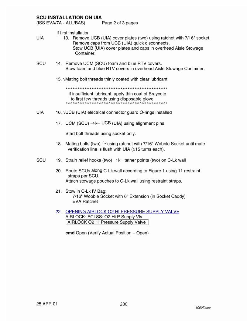
SCU INSTALLATION ON UIA (ISS EVA/7A - ALL/BAS) Page 2 of 3 pages
25 APR 01 10007.doc
If first installation UIA 13. Remove UCB (UIA) cover plates (two) using ratchet with 7/16" socket.
Remove caps from UCB (UIA) quick disconnects. Stow UCB (UIA) cover plates and caps in overhead Aisle Stowage Container.
SCU 14. Remove UCM (SCU) foam and blue RTV covers.
Stow foam and blue RTV covers in overhead Aisle Stowage Container. 15. �Mating bolt threads thinly coated with clear lubricant
*********************************************************** If insufficient lubricant, apply thin coat of Braycote to first few threads using disposable glove.
*********************************************************** UIA 16. �UCB (UIA) electrical connector guard O-rings installed 17. UCM (SCU) �|� UCB (UIA) using alignment pins
Start bolt threads using socket only. 18. Mating bolts (two) using ratchet with 7/16" Wobble Socket until mate
verification line is flush with UIA (�15 turns each). SCU 19. Strain relief hooks (two) �|� tether points (two) on C-Lk wall 20. Route SCUs along C-Lk wall according to Figure 1 using 11 restraint
straps per SCU. Attach stowage pouches to C-Lk wall using restraint straps.
21. Stow in C-Lk IV Bag:
7/16" Wobble Socket with 6" Extension (in Socket Caddy) EVA Ratchet
22. OPENING AIRLOCK O2 HI PRESSURE SUPPLY VALVE
AIRLOCK: ECLSS: O2 Hi P Supply Vlv AIRLOCK O2 Hi Pressure Supply Valve
cmd Open (Verify Actual Position – Open)
280
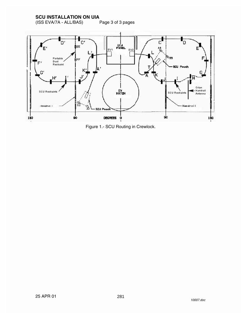
SCU INSTALLATION ON UIA (ISS EVA/7A - ALL/BAS) Page 3 of 3 pages
25 APR 01 10007.doc
Figure 1.- SCU Routing in Crewlock.
281

26 APR 01
This Page Intentionally Blank
282
SCU REMOVAL FROM UIA (ISS EVA/7A - ALL/BAS) Page 1 of 2 pages
09 APR 01 10009.doc
NOTE Procedure is written for simultaneous removal of two SCUs.
C-Lk 1. Unstow from C-Lk IV Bag:
7/16" socket with 6" extension (in socket caddy) EVA ratchet
E-Lk 2. Unstow UCM (SCU) foam and blue RTV covers from overhead Aisle
Stowage Container. Temporarily stow covers.
PSA 3. �SUIT SELECT sw (two) – OFF UIA 4. �PWR EV-1, 2 sw (two) – OFF
�PWR EV-1, 2 LEDs (four) – �WATER SUPPLY EV-1, 2 vlv (two) – CLOSE �OSCA control handle – ���� ��� ��� �
PCS 5. CLOSING AIRLOCK O2 HI PRESSURE SUPPLY VALVE
AIRLOCK: ECLSS: O2 Hi P Supply Vlv AIRLOCK O2 Hi Pressure Supply Valve
cmd Close (Verify Actual Position – Closed)
UIA 6. OXYGEN EMU 1, 2 vlv (two) � OPEN 7. OXYGEN ORLAN vlv � OPEN
NOTE The following step will vent oxygen from the UIA via the OSCA in order to depressurize the EMU O2 lines prior to removal of the SCU.
OSCA 8. Pull lock/unlock strap.
OSCA control handle �������� ��������
When purge no longer audible UIA 9. �EMU O2 SUPPLY PRESS gauge � 0
�ORLAN O2 SUPPLY PRESS gauge � 0 10. OXYGEN EMU 1,2 vlv (two) � CLOSE OSCA 11. Pull lock/unlock strap.
OSCA control handle ���� ��� ��� �� UIA 12. OXYGEN ORLAN vlv � CLOSE C-Lk 13. Remove SCU from stowage straps on C-Lk wall.
283

SCU REMOVAL FROM UIA (ISS EVA/7A - ALL/BAS) Page 2 of 2 pages
09 APR 01 10009.doc
UIA 14. Mating bolts (two) using ratchet with 7/16" socket (�15 turns each). 15. UCM (SCU) �|� UCB (UIA) SCU 16. Install UCM (SCU) blue RTV and foam covers. 17. Strain relief hooks (two) �|� tether points (two) on C-Lk wall 18. Remove stowage pouches from C-Lk restraint straps (leave DCM
connectors inside pouches). Stow SCUs.
C-Lk 19. Stow in C-Lk IV Bag:
7/16" socket with 6" extension (in socket caddy) EVA ratchet
20. OPENING AIRLOCK O2 HI PRESSURE SUPPLY VALVE
AIRLOCK: ECLSS: O2 Hi P Supply Vlv AIRLOCK O2 Hi Pressure Supply Valve
cmd Open (Verify Actual Position – Open)
284
METOX CANISTER O-RING CHANGEOUT (10 MINUTES) (ISS EVA/7A - ALL/BAS) Page 1 of 1 page
08 FEB 01 10020.doc
NOTE When handling the canister take caution to protect the state indicator from being inadvertently switched to the E position.
1. Unstow Metox canister, EMU Servicing Kit.
√Metox canister state indicator – R 2. Remove Metox canister caps.
Temporarily stow caps. 3. Remove old O-rings (two) from canister.
Stow O-rings in EMU Equipment Bag trash. 4. Unstow new Metox canister O-rings (two) from EMU Servicing Kit. 5. Install new O-rings on Metox canister inlet/outlet ports using a rolling
motion until O-rings are fully seated in groove. 6. Install canister caps. 7. √Metox canister state indicator – R 8. Record O-ring changeout in IMS. 9. Stow Metox canister, EMU Servicing Kit.
285

26 APR 01
This Page Intentionally Blank
286
����������
���� ��������������
��
���
��
��
�
�
��
��
��
��
��
�
287

����������
�
��������������������������� ��
��
���
��
��
�
�
��
��
��
��
��
�
288
PSA ACTIVATION AND CHECKOUT (10 MINUTES) (ISS EVA/7A - ALL/BAS) Page 1 of 1 page
08 FEB 01 10018.doc
PSA 1. MAIN POWER � ON
�MAIN POWER LED �
Wait 5 seconds until pixel test is complete. 2. �FAULT LED –
�No ‘FAULT’ messages displayed �No TEMP or WD faults displayed
3. IRU/UTILITY PWR sw � ON
�IRU/UTILITY PWR LED � �IRU Volts: 27.0 --- 29.0
4. SUIT SELECT sw (two) � ORL1,2
�ORL1,2 LEDs (two) – �ORL1,2 Volts: 27.4 --- 28.6
5. SUIT SELECT sw (two) � EMU1,2
�EMU1,2 LEDs (two) – �EMU1,2 Volts: 18.0 --- 19.0
PSA POWERDOWN (5 MINUTES)
PSA 6. SUIT SELECT sw (two) � OFF
�SUIT SELECT LEDs (four) � 7. �EMU MODE EMU 1,2 sw (two) � PWR 8. IRU/UTILITY POWER sw � OFF
�IRU/UTILITY POWER LED – 9. MAIN POWER sw � OFF
�MAIN POWER LED � 10. �Display � blank
289

26 APR 01
This Page Intentionally Blank
290
IRU ACTIVATION AND CHECKOUT (ISS EVA/7A - ALL/BAS) Page 1 of 5 pages
10 APR 01 10010.doc
EMU POWERUP AND CONFIGURATION NOTE
1. ‘PWR RESTART’ message occurs and BITE light is illuminated whenever EMU power is cycled.
2. Perform all DCM PWR switch throws with firm, deliberate action.
1. Unstow the following:
EMU Equipment Bag EMU Water Recharge Bag Comm cap for EMU 3 Cooling loop jumper
2. Attach EMU Equipment Bag to top of Cabin Air Rack.
Temporarily stow comm cap, cooling loop jumper in EMU Equipment Bag. 3. Velcro EMU Water Recharge Bag to wall below IRU.
Log new stowage location for bag in IMS. UIA 4. �PWR EV-1,2 sw (two) – OFF
�PWR EV-1,2 LEDs (four) � �EMU O2 SUPPLY PRESS gauge: 850 --- 950
C-Lk wall 5. Remove SCU 1 from stowage straps and pouch.
Transfer SCU to E-Lk. DCM 6. Remove DCM Cover.
Velcro to DCM. 7. SCU 1 �|� DCM
�SCU 1 locked 8. Helmet �|� HUT
Temporarily stow helmet. 9. Comm cap �|� electrical harness
Temporarily stow comm cap in arm of EMU. 10. PWR � BATT
CAUTION EMU must be on BATT power when UIA suit power is turned on.
PSA 11. �EMU MODE EMU 1,2 sw (two) � PWR
291

IRU ACTIVATION AND CHECKOUT (ISS EVA/7A - ALL/BAS) Page 2 of 5 pages
10 APR 01 10010.doc
12. MAIN POWER sw � ON
�MAIN POWER LED � 13. SUIT SELECT sw (two) � EMU 1,2
�EMU 1,2 LEDs (two) � �EMU 1,2 Volts: 18.0 --- 19.0
UIA 14. PWR EV-1 sw � ON
�PWR EV-1 EMU LED – DCM 15. PWR � SCU
AIRLOCK LCG HX CHARGE 16. Waist ring �|� HUT 17. Unstow cooling loop jumper, SCOF from EMU Equipment Bag.
Cooling loop jumper �|� Multiple Water Connector 18. Install SCOF. DCM 19. Temp control vlv � 7 20. O2 ACT � IV 21. �STATUS: H2O TEMP = ambient
Record H2O TEMP.
EMU H2O TEMP
22. FAN � ON, ‘NO VENT FLOW’ message, PRO
Record GMT.
EMU GMT : : : :
23. Wait 30 seconds, then:
Depress and hold pump priming valve on back of EMU (30 seconds maximum).
292

IRU ACTIVATION AND CHECKOUT (ISS EVA/7A - ALL/BAS) Page 3 of 5 pages
10 APR 01 10010.doc
24. �Air bubbles visible and mobile in cooling loop jumper �No unusual fan noise present
If no H2O flow detected at cooling loop jumper or if an unusual fan noise is present
25. Depress and hold pump priming valve (~30 seconds). 26. Repeat step 25 as necessary to initiate flow (~7 times during testing).
When no bubbles visible in cooling loop jumper DCM 27. �STATUS: H2O TEMP decrease from step 21
Record H2O TEMP.
EMU H2O TEMP
28. FAN � OFF 29. O2 ACT � OFF UIA 30. PWR EV-1 sw � OFF
�PWR EV-1,2 LEDs (four) � DCM 31. SCU 1 �|� DCM 32. Transfer SCU 1 to C-Lk.
Insert SCU in stowage pouch. 33. Remove SCU 2 from stowage straps and pouch.
Transfer SCU 2 to E-Lk. DCM 34. SCU 2 �|� DCM
�SCU 2 locked 35. PWR � BATT UIA 36. PWR EV-2 sw � ON
�PWR EV-2 EMU LED � DCM 37. PWR � SCU 38. Repeat steps 20 --- 29 for SCU 2, then: 39. Remove SCOF.
Stow SCOF in EMU Equipment Bag.
293

IRU ACTIVATION AND CHECKOUT (ISS EVA/7A - ALL/BAS) Page 4 of 5 pages
10 APR 01 10010.doc
EMU WATER FILL IRU 40. �H2O OUTLET vlv (rotary) � CLOSED
�POWER sw � OFF �POWER LED � �PUMP sw – OFF �PUMP LED �
41. EMU Water Recharge Bag �|� H2O IN port UIA 42. �WATER EV-2 REG vlv � SUPPLY 43. WATER EV-2 SUPPLY vlv � OPEN PSA 44. IRU/UTILITY POWER sw � ON
�IRU/UTILITY POWER LED � �IRU volts: 27.0 --- 29.0
NOTE
The following step powers on the IRU. Need to verify the POWER, PRESS, and TEMP LEDs briefly illuminate when IRU POWER is taken ON.
IRU 45. POWER sw � ON
�POWER, PRESS, TEMP LEDs (three) � at startup 46. Wait until 2.5-second LED and pixel check complete.
�POWER LED remains � 47. H2O outlet vlv (rotary) EMU SUPPLY. IRU 48. PUMP sw � ON
�PUMP LED � �QUANTITY Display – �
DCM 49. �STATUS: H2O WP ~ 13.5 psi, stable for ~30 seconds (indicates charging
complete) UIA 50. WATER EV-2 SUPPLY vlv � CLOSE IRU 51. PUMP sw � OFF
�PUMP LED � 52. H2O OUTLET vlv (rotary) CLOSED.
294

IRU ACTIVATION AND CHECKOUT (ISS EVA/7A - ALL/BAS) Page 5 of 5 pages
10 APR 01 10010.doc
53. Record value from QUANTITY display. Report quantity to MCC-H as comm permits.
Date H2O Quantity
54. POWER sw � OFF
�POWER LED � 55. EMU Water Recharge Bag �|� H2O IN port
Stow bag in floor bin. 56. Install cap on H2O IN port. PSA 57. IRU/UTILITY POWER sw � OFF
�IRU/UTILITY POWER LED �
295

26 APR 01
This Page Intentionally Blank
296

EMU/AIRLOCK COMM ACTIVATION AND CHECKOUT (30 MINUTES) (ISS EVA/7A - ALL/BAS) Page 1 of 8 pages
16 APR 01 10019.doc
1. Unstow EACP Y cable, headset. EV1 2. �Comm cap �|� electrical harness
CAUTION Minimize fan operation with O2 ACT – OFF (~2 minutes).
HARDLINE CHECK
EACP 3. EACP Y cable �|� EACP ATU 4,5 4. EACP Y cable �|� ATU
�ATUs enabled �No calls configured (display – blank)
EACP 5. PWR sw � ON
�EMU1,2 mode sel (two) – DUAL IV ATU 6 6. Headset �|� ATU
Headset Control � DUAL 7. PTT pb � Press
5 pb � Press
�Display – ‘5T’ ATU 4,5 8. PTT pb � Press
5 pb � Press
�Display – ‘5T’ DCM 9. FAN � ON 10. Install SCOF, lock. DCM 11. O2 ACT � IV, ‘NO VENT FLOW’ message, PRO EV1,IV 12. Don comm cap, headset. DCM 13. �COMM mode – HL 14. Perform IV/EV comm check. EV1 DCM 15. FAN � OFF 16. O2 ACT � OFF
297

EMU/AIRLOCK COMM ACTIVATION AND CHECKOUT (30 MINUTES) (ISS EVA/7A - ALL/BAS) Page 2 of 8 pages
16 APR 01 10019.doc
UIA 17. PWR EV-2 sw � OFF
�PWR EV-2 EMU LED � DCM 18. SCU 2 �|� DCM 19. Transfer SCU 2 to C-Lk.
Insert SCU 2 in stowage pouch. 20. Remove SCU 1 from stowage pouch.
Transfer SCU 1 to E-Lk. DCM 21. SCU �|� DCM
�SCU locked 22. PWR � BATT UIA 23. PWR EV-1 sw � ON
�PWR EV-1 EMU LED � DCM 24. PWR � SCU 25. FAN � ON 26. O2 ACT � IV, ‘NO VENT FLOW’ message, PRO EV1,IV 27. Don comm cap and headset. 28. Perform IV/EV comm check. IV ATU 29. HANG UP pb � Press 4,5,6
5 pb � Press ATU 6 30. 1 pb � Press
�Display – ‘1TG’ EACP 31. PWR sw � OFF
NOTE Steps 32 --- 38 may be performed by MCC-H.
CAUTION Only one UHF string should be powered on at a time to avoid hardware damage.
298

EMU/AIRLOCK COMM ACTIVATION AND CHECKOUT (30 MINUTES) (ISS EVA/7A - ALL/BAS) Page 3 of 8 pages
16 APR 01 10019.doc
CHECKING ALTERNATE RADIOS/414.2 MHz IV PCS 32. VERIFYING UHF1 IS POWERED OFF MCC-H C&T: UHF
UHF Overview
Verify RPCM LAD52B A RPC 08 – Open
CONFIGURING FOR UHF 2/414.2 MHz/LOW POWER 33. POWERING ON UHF 2
C&T: UHF: RPCM LA1B H RPC 04 RPCM LA1B H RPC 04
�Close Cmd � Enabled
‘RPC Position’
cmd Close (Verify – Cl)
34. ENABLING UHF 2 CYCLIC I/O
C&T: UHF: UHF 2 Command UHF 2 Command
‘Cyclic I/O and Bus FDIR’
sel CB CT-2 RT Status
CB CT-2 RT Status ‘RT Address and Name: 23 UHF-2’
cmd Enable Execute (Verify RT status – Ena)
35. VERIFYING UHF 2 BUS FDIR INHIBIT
C&T: UHF UHF Overview
‘UHF 2 Command’
Verify Bus FDIR – Inhibit 36. VERIFYING UHF 2 FAIL RECOVERY INHIBIT
C&T: UHF UHF Overview
‘UHF 2 Command’
Verify Fail Recovery – Inhibited 37. VERIFYING UHF 2 CONFIGURATION
C&T: UHF UHF Overview
‘Configuration’
299

EMU/AIRLOCK COMM ACTIVATION AND CHECKOUT (30 MINUTES) (ISS EVA/7A - ALL/BAS) Page 4 of 8 pages
16 APR 01 10019.doc
Verify Xmit Power � Low Verify Frequency: 414.2
38. POWERING ON AUAI2S FOR USE
C&T: Audio Audio Overview
sel AUAI2S
AUAI 2 S
sel RPCM LAD11B A RPC02
RPCM LAD11B A RPC02
cmd Close (Verify – Cl)
AUAI 2 S
‘AUAI2S BUS I/O’
cmd Enable (Verify AUAI2S BUS I/O – Ena)
‘AUAI2S State’
cmd Active (Verify AUAI2S State � Active) IV ATU 6 39. DIAL ANS pb � Press
2nd pb � Press UHF pb � Press 3 pb � Press
�Display – ‘UH3T’
EV1 DCM 40. COMM mode � PRI
�Comm FREQ � LOW 41. Perform IV/EV comm check. IV ATU 6 42. HANG UP pb � Press
CHECKING PRIMARY RADIOS/414.2 MHz NOTE
Steps 43 --- 48 may be performed by MCC-H. IV PCS 43. DISABLING UHF 2 CYCLIC I/O MCC-H C&T: UHF: UHF 2 Command
UHF 2 Command ‘Cyclic I/O and Bus FDIR’
300
EMU/AIRLOCK COMM ACTIVATION AND CHECKOUT (30 MINUTES) (ISS EVA/7A - ALL/BAS) Page 5 of 8 pages
16 APR 01 10019.doc
sel CB CT-2 RT Status
CB CT-2 RT Status ‘RT Address and Name: 23 UHF-2’
cmd Inhibit Execute (Verify RT Status – Inh)
44. POWERING OFF UHF 2
C&T: UHF: RPCM LA1B H RPC 04 RPCM LA1B H RPC 04
‘RPC Position’
cmd Open (Verify RPC – Op)
CAUTION UHF 2 must be powered off prior to powering on UHF 1 to avoid hardware damage.
45. POWERING ON UHF 1
C&T: UHF: RPCM LAD5 2B A RPC 08 RPCM LAD5 2B A RPC 08
�Close Cmd � Enabled
‘RPC Position’
cmd Close (Verify – Cl)
46. ENABLING UHF 1 CYCLIC I/O
C&T: UHF: UHF 1 Command UHF 1 Command
‘Cyclic I/O and Bus FDIR’
sel CB CT-1 RT Status
CB CT-1 RT Status ‘RT Address and Name: 23 UHF-1’
cmd Enable Execute (Verify RT Status – Enable)
47. VERIFYING UHF 1 BUS FDIR INHIBIT C&T: UHF UHF Overview
‘UHF 1 Command’
Verify Bus FDIR � Inhibit
301
EMU/AIRLOCK COMM ACTIVATION AND CHECKOUT (30 MINUTES) (ISS EVA/7A - ALL/BAS) Page 6 of 8 pages
16 APR 01 10019.doc
48. VERIFYING UHF 1 FAIL RECOVERY INHIBIT C&T: UHF UHF Overview
‘UHF 1 Command’
Verify Fail Recovery – Inhibited 49. VERIFYING UHF 1 CONFIGURATION
C&T: UHF UHF Overview
Verify Xmit Power � Low Verify Frequency: 414.2
IV ATU 6 50. DIAL ANS pb � Press
2nd pb � Press UHF pb � Press 1 pb � Press
�Display ‘UH1T’
EV1 DCM 51. �COMM mode � PRI
�Comm FREQ � LOW EV1,IV 52. Perform IV/EV comm check. IV ATU 6 53. HANG UP pb � Press
SPACE-TO-GROUND CHECK IV PCS 54. CONFIGURING EVA PUBLIC CALL
C&T: Audio Audio Overview
sel IAC(X) Call Select (where X = powered and active IAC, 1 or 2)
IAC(X) Call Select
‘Public1’
sel Call Setup
Public 1 Call Select
cmd UHF 1
IAC(X) Call Select ‘Public1’
�GND 2 – ‘TL’ �UHF 1 – ‘TL’
302

EMU/AIRLOCK COMM ACTIVATION AND CHECKOUT (30 MINUTES) (ISS EVA/7A - ALL/BAS) Page 7 of 8 pages
16 APR 01 10019.doc
ATU 6 55. PTT pb � Press 1 pb � Press
�Display – ‘1TG’
EV1 56. Verify EMU data, RF comm with MCC-H. 57. Doff comm caps. DCM 58. FAN � OFF 59. O2 ACT � OFF 60. Remove SCOF.
Stow SCOF in EMU Equipment Bag. IV PCS 61. DECONFIGURING EVA PUBLIC CALL
C&T: Audio Audio Overview
sel IAC(X) Call Select (where X = powered and active IAC, 1 or 2)
IAC(X) Call Select
‘Public1’
sel Hangup
Public 1 Call Hangup
cmd UHF 1
IAC(X) Call Select ‘Public1’
�UHF 1 not present
62. POWERING OFF AUAI2S
C&T: Audio Audio Overview
sel AUAI2S
AUAI2 S
sel RPCM LAD11B A RPC 02
RPCM LAD11B A RPC 02
‘RPC Position’
303

EMU/AIRLOCK COMM ACTIVATION AND CHECKOUT (30 MINUTES) (ISS EVA/7A - ALL/BAS) Page 8 of 8 pages
16 APR 01 10019.doc
cmd Open (Verify PRC – Op)
AUAI 2S ‘AUAI2S BUS I/O’
cmd Inhibit (Verify AUAI2S Bus I/O – Inh)
‘AUAI2S State’
cmd Standby (Verify AUAI2S State – Standby)
304
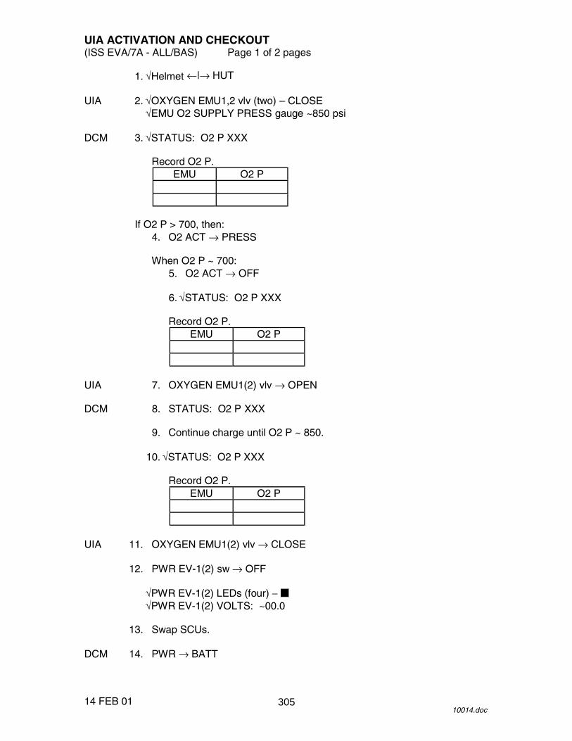
UIA ACTIVATION AND CHECKOUT (ISS EVA/7A - ALL/BAS) Page 1 of 2 pages
14 FEB 01 10014.doc
1. √Helmet ←|→ HUT UIA 2. √OXYGEN EMU1,2 vlv (two) – CLOSE
√EMU O2 SUPPLY PRESS gauge ~850 psi DCM 3. √STATUS: O2 P XXX
Record O2 P. EMU O2 P
If O2 P > 700, then:
4. O2 ACT → PRESS
When O2 P ~ 700: 5. O2 ACT → OFF 6. √STATUS: O2 P XXX
Record O2 P. EMU O2 P
UIA 7. OXYGEN EMU1(2) vlv → OPEN DCM 8. STATUS: O2 P XXX 9. Continue charge until O2 P ~ 850. 10. √STATUS: O2 P XXX
Record O2 P. EMU O2 P
UIA 11. OXYGEN EMU1(2) vlv → CLOSE 12. PWR EV-1(2) sw → OFF
√PWR EV-1(2) LEDs (four) − √PWR EV-1(2) VOLTS: ~00.0
13. Swap SCUs. DCM 14. PWR → BATT
305

UIA ACTIVATION AND CHECKOUT (ISS EVA/7A - ALL/BAS) Page 2 of 2 pages
14 FEB 01 10014.doc
PSA 15. SUIT SELECT sw → EMU1(2) UIA 16. PWR EV-1(2) sw → ON
√PWR EV-1(2) EMU LED − √PWR EV-1(2) VOLTS: 18.0 --- 19.0
DCM 17. PWR → SCU 18. Repeat steps 3 --- 12 on SCU 2. UIA 19. √PWR EV-1,2 sw (two) − OFF PSA 20. SUIT SELECT sw (two) → OFF
√SUIT SELECT LEDs (four) − 21. MAIN POWER sw → OFF
√MAIN POWER LED − DCM 22. SCU 2 ←|→ DCM
Install DCM cover. C-Lk 23. Insert SCU 2 in stowage pouch. wall
306

BCA ACTIVATION AND CHECKOUT (20 MINUTES) (ISS EVA/7A - ALL/BAS) Page 1 of 3 pages
24 APR 01 10016.doc
1. Unstow the following: 7/16" socket from C-Lk IV Bag REBA/BSA cable
BSA door 2. Launch lock using 7/16" socket (~ 2 turns)
Temporarily stow launch lock for return to ground. BSA 3. Install EHIP and PGT batteries in BSA.
Log new location for batteries in IMS. 4. Close BSA door. BSA 5. REBA/BSA cable �|� AUX CHARGE PORT REBA 6. Deploy and demate REBA jumper cables. 7. REBA jumper cables (two) �|� REBA/BSA cable
NOTE Power on all four battery chargers within 5 seconds to avoid startup anomalies.
BCA 8. MAIN POWER sw (four) � ON
�MAIN POWER LEDs (four) �
Wait 20 seconds until pixel test is complete. 9. �Display readable and CHARGE column reads: CH: -
V: ---- A: ----
10. MODE sw (four) � STOP 11. DATA sw (four) � HISTORY
If display garbled/blank or ‘Look At’ on any display If BC1 or BC2
12. On affected BC, MAIN POWER sw � OFF
If BC3 or BC4 13. On BC3 and BC4, MAIN POWER sw � OFF 14. Repeat steps 8 --- 11. 15. Verify channel profile according to Table 1 by toggling
DATA sw � HISTORY
307
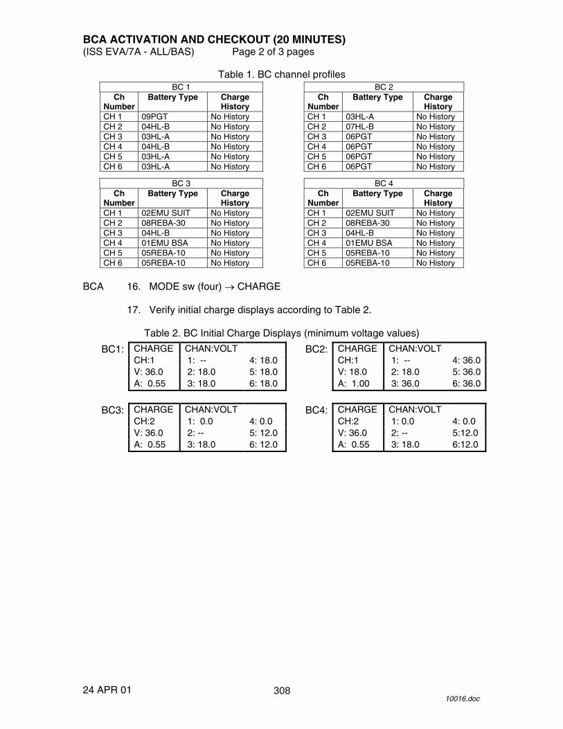
BCA ACTIVATION AND CHECKOUT (20 MINUTES) (ISS EVA/7A - ALL/BAS) Page 2 of 3 pages
24 APR 01 10016.doc
Table 1. BC channel profiles BC 1 BC 2
Ch Number
Battery Type Charge History
Ch Number
Battery Type Charge History
CH 1 09PGT No History CH 1 03HL-A No History CH 2 04HL-B No History CH 2 07HL-B No History CH 3 03HL-A No History CH 3 06PGT No History CH 4 04HL-B No History CH 4 06PGT No History CH 5 03HL-A No History CH 5 06PGT No History CH 6 03HL-A No History CH 6 06PGT No History
BC 3 BC 4
Ch Number
Battery Type Charge History
Ch Number
Battery Type Charge History
CH 1 02EMU SUIT No History CH 1 02EMU SUIT No History CH 2 08REBA-30 No History CH 2 08REBA-30 No History CH 3 04HL-B No History CH 3 04HL-B No History CH 4 01EMU BSA No History CH 4 01EMU BSA No History CH 5 05REBA-10 No History CH 5 05REBA-10 No History CH 6 05REBA-10 No History CH 6 05REBA-10 No History
BCA 16. MODE sw (four) � CHARGE 17. Verify initial charge displays according to Table 2.
Table 2. BC Initial Charge Displays (minimum voltage values)
BC1: CHARGE CHAN:VOLT BC2: CHARGE CHAN:VOLT CH:1 1: -- 4: 18.0 CH:1 1: -- 4: 36.0 V: 36.0 2: 18.0 5: 18.0 V: 18.0 2: 18.0 5: 36.0 A: 0.55 3: 18.0 6: 18.0 A: 1.00 3: 36.0 6: 36.0
BC3: CHARGE CHAN:VOLT BC4: CHARGE CHAN:VOLT CH:2 1: 0.0 4: 0.0 CH:2 1: 0.0 4: 0.0 V: 36.0 2: -- 5: 12.0 V: 36.0 2: -- 5:12.0 A: 0.55 3: 18.0 6: 12.0 A: 0.55 3: 18.0 6:12.0
308

BCA ACTIVATION AND CHECKOUT (20 MINUTES) (ISS EVA/7A - ALL/BAS) Page 3 of 3 pages
24 APR 01 10016.doc
Figure 1.- BSA Door Decal.
309

26 APR 01
This Page Intentionally Blank
310
����������
��� � �� �����
��
��
��
�
��
��
���
�
��
�
��
311
����������
�
������������������������������
��
��
��
�
��
��
���
�
��
�
��
312
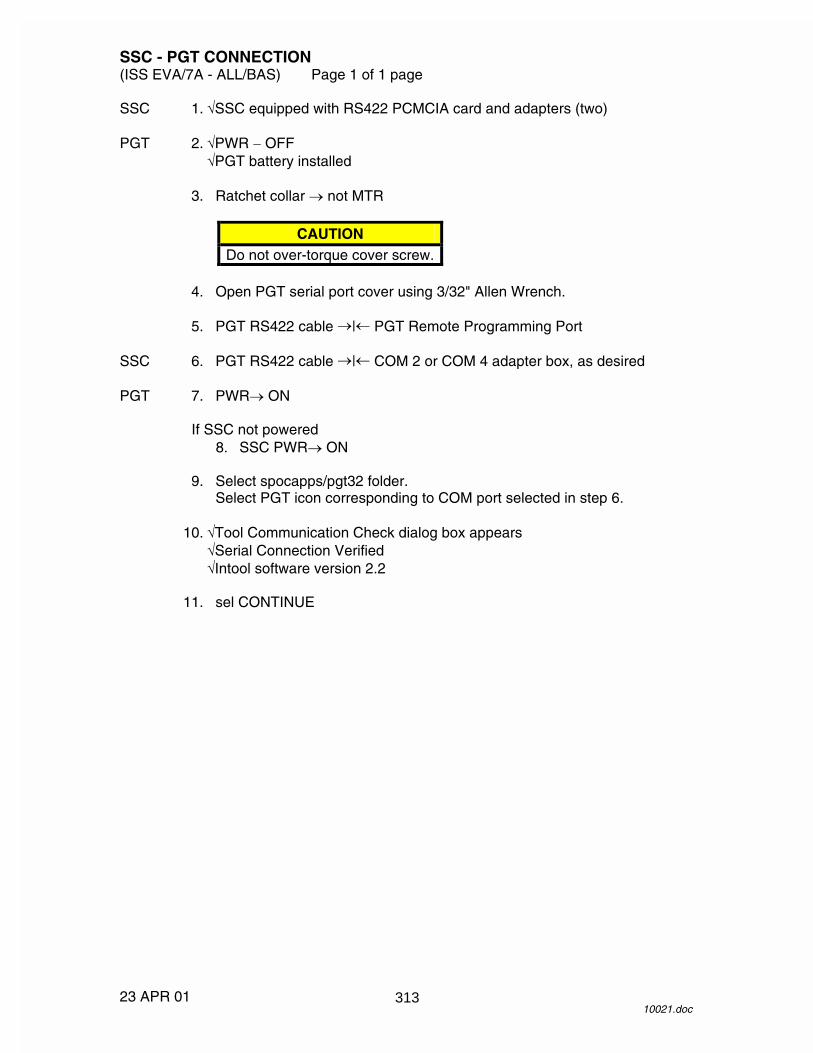
SSC - PGT CONNECTION (ISS EVA/7A - ALL/BAS) Page 1 of 1 page
23 APR 01 10021.doc
SSC 1. �SSC equipped with RS422 PCMCIA card and adapters (two) PGT 2. �PWR � OFF
�PGT battery installed 3. Ratchet collar � not MTR
CAUTION Do not over-torque cover screw.
4. Open PGT serial port cover using 3/32" Allen Wrench. 5. PGT RS422 cable �|� PGT Remote Programming Port SSC 6. PGT RS422 cable �|� COM 2 or COM 4 adapter box, as desired PGT 7. PWR� ON
If SSC not powered 8. SSC PWR� ON 9. Select spocapps/pgt32 folder.
Select PGT icon corresponding to COM port selected in step 6. 10. �Tool Communication Check dialog box appears
�Serial Connection Verified �Intool software version 2.2
11. sel CONTINUE
313

26 APR 01
This Page Intentionally Blank
314

PROGRAM PGT SETTINGS (ISS EVA/7A - ALL/BAS) Page 1 of 1 page
14 FEB 01 10022.doc
1. Perform {SSC - PGT CONNECTION} (SODF: ISS EVA: TOOL CONTINGENCIES) to enter remote software.
If loading settings from a set file in C:\SPOCAPPS\PGT32\SETTINGS
2. sel FILE, OPEN sel desired settings file, OPEN
3. Select TORQUE/REVOLUTIONS SETTINGS tab in Pistol Grip Tool
Remote Software window. 4. Enter changes to table as necessary. 5. Select SPEED & POWER MANAGEMENT SETTINGS tab. 6. Enter changes to table as necessary. 7. �Ratchet collar – not MTR 8. Select TOOL, SEND DATA TO TOOL.
Select desired tables for upload. 9. �All sent settings – black on gray (programmed successfully)
If saving settings to a file 10. sel FILE, SAVE AS…
Type in new file name, SAVE. 11. Perform {SSC - PGT DISCONNECTION} (SODF: ISS EVA: TOOL
CONTINGENCIES), then: 12. Go to {PGT SETTINGS VERIFICATION} (SODF: ISS EVA: TOOL
CONTINGENCIES).
315

26 APR 01
This Page Intentionally Blank
316

PGT SETTINGS VERIFICATION(EVA/7A - ALL/GEN) Page 1 of 1 page
19 OCT 0010023.doc
PGT 1. PWR → ON
2. If tool has not been calibratedRatchet collar → not MTRSpeed collar → CAL
Press, release trigger to calibrate.
√Display – ‘CAL PASSED ’
3. Ratchet collar → MTRSpeed collar → not CAL
4. To verify programmed settings, cycle MODE/torque collar/speed collarand compare with {PGT STANDARD SETTINGS} (SODF: EVA:NOMINAL: CHECKOUTS) or other desired settings table.
5. PWR → OFF
317

26 APR 01
This Page Intentionally Blank
318

����������������� �����
������������������� � �����������������
�������������������
� ��� �������������������� ���!���������"��#���$��#%&&�#��%&'���%(�)��������)��%%��#%&��&$�&#��� !��*��)�
�
� +��√,��-*���-�..���/�����0�,��� 1�� ��.����&���%$���2�
��.��%%�!�$���(�����,%0��%%�3���.��%%�����&���%$�(�����,��(%&�4 �
�
� ���√(%5&�%�(��$�����&���%$�67�.���2�8����������� 9�� ��.�-��4������6� �.��6�6������
� :��√��������&���%$�(�����%������67�.���2�8����������� �� ����������������7.����� ;�� ��.�������
� <��√�=��������6����67��.�>�6�7��=7� ����� ���� �������7����=��������6����������$�!���.�-��%?�7���,�������&���%$�
67�.���2�8���� ���� $�����"��#�$��(��#%&&�#��%&'���%(�)��������)��%%��
#%&��&$�&#��� ���
319

26 APR 01
This Page Intentionally Blank
320

SSC - PGT DISCONNECTION (ISS EVA/7A - ALL/BAS) Page 1 of 1 page
26 APR 01 10025.doc
PGT 1. PWR � OFF 2. PGT-RS422 cable �|� PGT SSC PGT-RS422 cable �|� SSC
CAUTION Do not over-torque cover screw.
3. Close PGT serial port cover using 3/32" Allen Wrench attached to PGT
RS422 cable. 4. Shut down SSC as required. 5. Stow: C-Lk PGT in C-Lk IV Bag E-Lk PGT-RS422 cable
RS422 PCMIA card and adapters
321

26 APR 01
This Page Intentionally Blank
322

PGT CONTINGENCIES(EVA/7A - ALL/GEN) Page 1 of 1 page
18 OCT 0010026.doc
MESSAGE CORRECTIVE ACTIONSBATTRY HITEMP If alternate battery available; power off, change battery. Otherwise; power
off, switch to Ratchet mode.BATTRY LOTEMP(blinking)
Drive tool with no load to increase battery temperature. If no joy andalternate battery available; power off, change battery. Otherwise; poweroff, switch to Ratchet mode.
BATTRY LOVOLT(blinking)
Continue using until tool is unable to deliver sufficient torque. If no joy andalternate battery available; power off, change battery. Otherwise; poweroff, switch to Ratchet mode.
CAL FAILED Press, release trigger to repeat calibration. If no joy; power cycle,calibrate. If no joy; power off, switch to Ratchet mode.
COLLAR ERROR Cycle torque and speed collars to clear error. If no joy; power cycle,calibrate. If no joy; power off, switch to Ratchet mode.
COMPAR ERROR Cycle torque collar and A/B mode switch. If no joy; power cycle, calibrate.If no joy; power off, switch to Ratchet mode.
EEPROM WR ERR(blinking)
Power cycle, calibrate. If no joy; power off, switch to Ratchet mode.
HI TORQ If fault occurs during engagement and MTL did not slip, ignore message.Otherwise; power cycle, calibrate. If no joy; power off, switch to Ratchetmode.
HICURR Reattempt operation. If no joy; power cycle, calibrate. If no joy; power off,switch to Ratchet mode.
HYBRID HITEMP Power cycle, calibrate. If no joy; power off, switch to Ratchet mode.LO TORQ Reattempt operation until desired torque is reached. If no joy; power
cycle, calibrate. If no joy; power off, switch to Ratchet mode.LOCURR Reattempt operation. If no joy; power cycle, calibrate. If no joy; power off,
switch to Ratchet mode.LOG IS FULL(blinking)
Continue operation.
MOTOR HITEMP Power off, switch to Ratchet mode.OVER CURR Power cycle, calibrate. If no joy; power off, switch to Ratchet mode.SLFTST FAIL X Power cycle, calibrate. If no joy; power off, switch to Ratchet mode.
323

26 APR 01
This Page Intentionally Blank
324
����������
���� ����������
��
��
��
���
��
�
��
��
��
��
325

����������
�
���������������������������� ��
��
��
��
���
��
�
��
��
��
��
326

NORMAL EVA STATUS (ISS EVA/7A - ALL/BAS) Page 1 of 1 page
05 MAR 01 10033.doc
DCM CONFIG
MAL INDEX
NORMAL EVA STATUS
05 MAR 01 1 10033.doc
O2 POS EVA TIME EV HH:MM since PWR-BATT TIME LF/ Limit consum
HH:MM remaining at present use rate
% O2 (PWR) LF Displayed if not limiting consumable SUIT P 4.2 --- 4.4 psid O2 P 150 --- 900 psia SOP P 5800 --- 6800 psia SUBLM P 2.0 --- 4.2 psia BAT VDC 16.4 --- 17.0 BAT AMP 3.0 --- 4.0 RPM 19.0 --- 20.0 K CO2 0.2 --- 0.5 mm H2O TEMP 32 --- 75° F H2O GP/WP 14.0 --- 16.0 psid GAUGE 4.2 --- 4.4 psid
327

26 APR 01
This Page Intentionally Blank
328
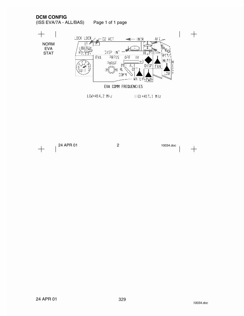
DCM CONFIG (ISS EVA/7A - ALL/BAS) Page 1 of 1 page
24 APR 01 10034.doc
NORM EVA STAT
24 APR 01 2 10034.doc
F R E Q
329

26 APR 01
This Page Intentionally Blank
330

EMU MALFUNCTION INDEX (ISS EVA/7A - ALL/BAS) Page 1 of 1 page
05 MAR 01 10037.doc
DCS
EMU MALFUNCTION INDEX ABORT EVA 6 PWR LF (%) 23 AIR FLOW CONT 21 RESRV H2O ON 17 BATT AMPS HI 9 RLF V FAIL 22 BATT VDC LOW 10 SET H2O OFF 23 BITE light 22 SET O2 EVA 23 COMM FAIL 20 SET O2 PRESS 23 CO2 HIGH 19 SET PWR SCU 23 DCS 4 SOP O2 ON 8 FAN SW OFF 23 SOP P LOW 13 H2O GP LOW 16 SUBL P 15 H2O IS OFF 23 SUIT P EMERG 23 LIMITS BAD 22 SUIT P HIGH 12 MONITOR CO2 19 SUIT P LOW 11 NO VENT FLOW 18 TERMINATE EVA 7 O2 IS OFF 23 TIME LF: XX 23 O2 LF (%) 23 VENT SW FAIL 22 O2 USE HIGH 14
05 MAR 01 3 10037.doc
331

26 APR 01
This Page Intentionally Blank
332
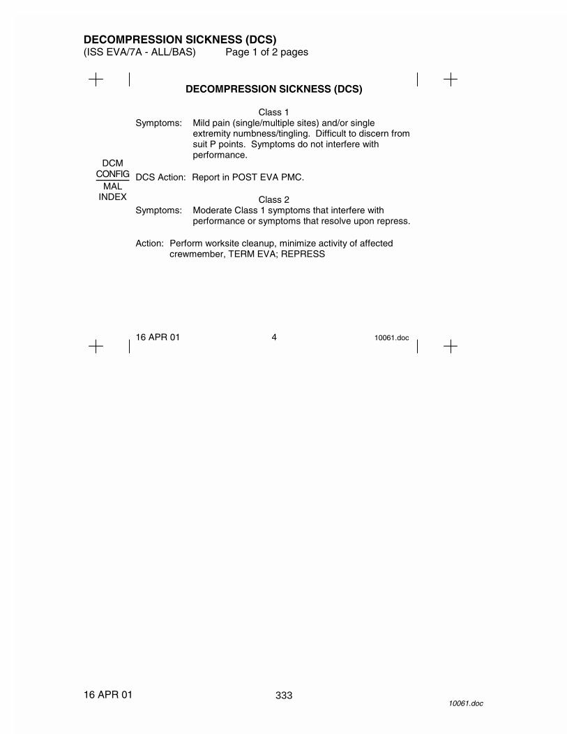
DECOMPRESSION SICKNESS (DCS) (ISS EVA/7A - ALL/BAS) Page 1 of 2 pages
16 APR 01 10061.doc
DCM CONFIG
MAL INDEX
DECOMPRESSION SICKNESS (DCS)
Class 1 Symptoms: Mild pain (single/multiple sites) and/or single
extremity numbness/tingling. Difficult to discern from suit P points. Symptoms do not interfere with performance.
DCS Action: Report in POST EVA PMC.
Class 2 Symptoms: Moderate Class 1 symptoms that interfere with
performance or symptoms that resolve upon repress. Action: Perform worksite cleanup, minimize activity of affected
crewmember, TERM EVA; REPRESS
16 APR 01 4 10061.doc
333

DECOMPRESSION SICKNESS (DCS) (ISS EVA/7A - ALL/BAS) Page 2 of 2 pages
16 APR 01 10061.doc
ABORT
EVA TERM EVA
DECOMPRESSION SICKNESS (DCS) (CONT)
Class 3 Symptoms: Severe Class 1 symptom or migratory,
trunkal/multiple site numbness/tingling, unusual headache.
Action: Assist affected crewmember to C-Lk, safe worksite,
TERM EVA; REPRESS.
Class 4 Symptoms: Serious symptom – central neurological,
cardiopulmonary Action: ABORT EVA.
Assisted return of affected crewmember to C-Lk, repress affected crewmember solo. Unaffected crewmember safe worksite, TERM EVA; REPRESS.
16 APR 01 5 10061.doc
334

ABORT EVA (ISS EVA/7A - ALL/BAS) Page 1 of 1 page
05 MAR 01 10038.doc
DCS
ABORT EVA
05 MAR 01 6 10038.doc
BOTH: Ingress C-Lk. Unhook from reel. Outer (EV) Hatch – close and lock Go to EMERGENCY CREWLOCK REPRESS decal (airlock hatches).
335

26 APR 01
This Page Intentionally Blank
336

TERMINATE EVA (ISS EVA/7A - ALL/BAS) Page 1 of 1 page
05 MAR 01 10039.doc
SOP ON
BATT AMPS
TERMINATE EVA 1. Ingress C-Lk. 2. Connect SCU. UIA 3. PWR EV-1(2) sw – ON 4. √OXYGEN EMU1(2) vlv − OPEN DCM 5. PWR – SCU (fwd) 6. WATER – OFF (fwd) 7. √SUIT P ≥ 3.3 and stable 8. Monitor EMU status. 9. Coordinate Ingress with EV1(2).
05 MAR 01 7 10039.doc
NOTE If fan stops during power transfer:
Cycle FAN sw – OFF,ON
WARNING If terminating due to BATT AMPS HIGH (system short), do not perform step 3.
337

26 APR 01
This Page Intentionally Blank
338

SOP O2 ON (ISS EVA/7A - ALL/BAS) Page 1 of 1 page
11 APR 01 10040.doc
ABORT
EVA TERM EVA
SOP O2 ON 1. Go to ABORT EVA, 6. >>
11 APR 01 8 10040.doc
NOTE Message triggered when:
SUIT P < 4.05 and SOP RATE > 36.0 psi/min.
SOP O2 ON TIME LF HH’MM
339

26 APR 01
This Page Intentionally Blank
340

BATT AMPS HIGH (ISS EVA/7A - ALL/BAS) Page 1 of 1 page
11 APR 01 10041.doc
BATT VDC SUIT
P LOW
BATT AMPS HIGH If BAT VDC < 16.4:
1. Helmet purge vlv – op 2. FAN – OFF 3. WATER – OFF
If BAT AMP without fan 0.7 --- 1.3 (fan short): 4. Go to TERM EVA, 7. >>
If BAT AMP without fan > 1.3 (system short): 5. Notify IV/EV of impending communication loss 6. PWR – SCU, do not take UIA EV-1(2) PWR � ON 7. Go to TERM EVA, 7. >>
If BAT VDC � 16.4 (amp sensor fail): 8. �Fan RPM 19.0 --- 20.0 K: 9. Continue EVA, monitor BAT VDC, RPM.
11 APR 01 9 10041.doc
BATT AMPS HI BAT AMPS X.X BAT VDC XX.X
NOTE Message triggered when AMPS > 5.0. Normal BATT AMP: 3.0 --- 4.0. Normal BATT AMP without fan: 0.7 --- 1.3.
341

26 APR 01
This Page Intentionally Blank
342

BATT VDC LOW (ISS EVA/7A - ALL/BAS) Page 1 of 1 page
11 APR 01 10042.doc
SOP ON
BATT AMPS
BATT VDC LOW If fan RPMS degraded and/or communication lost:
1. Go to TERM EVA, 7. >> If communication and fan normal (sensor fail):
2. Continue EVA.
11 APR 01 10 10042.doc
NOTE Message triggered when VOLTS < 15.7. Normal BATT VDC: 16.4 --- 17.0. Normal Fan RPM: 19.0 --- 20.0K.
BATT VDC LOW BAT VDC XX.X
343

26 APR 01
This Page Intentionally Blank
344

SUIT P LOW (ISS EVA/7A - ALL/BAS) Page 1 of 1 page
05 MAR 01 10043.doc
SUIT P HI
SOP P LOW
SUIT P LOW If ‘O2 USE HIGH’ message present:
1. Go to ABORT EVA, 6. >> If ‘O2 USE HIGH’ message not present:
2. Continue EVA, monitor SUIT P, SOP P, and gauge. If gauge < 4.0 and SOP P decreasing:
3. Go to TERM EVA, 7. >>
05 MAR 01 11 10043.doc
NOTE Message triggered when SUIT P < 4.05.
SUIT P LOW SUIT P X.X
345

26 APR 01
This Page Intentionally Blank
346

SUIT P HIGH (ISS EVA/7A - ALL/BAS) Page 1 of 1 page
05 MAR 01 10044.doc
BATT VDC SUIT
P LOW
SUIT P HIGH If O2 RATE > 7.0 or SOP RATE > 8:
1. Go to TERM EVA, 7. >> If O2 RATE < 7.0 and SOP RATE ≤ 8:
2. Monitor SUIT P, SOP P, and gauge. 3. Continue EVA.
05 MAR 01 12 10044.doc
SUIT P HIGH O2 RATE XX.X SOP RATE XXX
NOTE Message triggered when SUIT P > 4.55. Normal O2 RATE ≈1.7 psi/min.
347

26 APR 01
This Page Intentionally Blank
348

SOP P LOW (ISS EVA/7A - ALL/BAS) Page 1 of 1 page
05 MAR 01 10045.doc
O2
USE SUBLM PRESS
SOP P LOW 1. Go to TERM EVA, 7. >>
05 MAR 01 13 10045.doc
SOP P LOW SOP P XXX0 SOP RATE XXX
NOTE Message triggered when SOP P < init SOP P – 600 (SOP P initialized at EMU powerup).
349

26 APR 01
This Page Intentionally Blank
350

O2 USE HIGH (ISS EVA/7A - ALL/BAS) Page 1 of 1 page
05 MAR 01 10046.doc
SUIT P HI
SOP P LOW
O2 USE HIGH If ‘SUIT P LOW’ message present:
1. Go to ABORT EVA, 6. >> If O2 P erratic or ≈ 0:
2. Continue EVA. 3. Recharge O2 periodically. >>
If O2 RATE > 7.0: 4. Go to TERM EVA, 7. >>
Otherwise: 5. Recharge O2 as required. 6. Continue EVA.
05 MAR 01 14 10046.doc
O2 USE HIGH O2 RATE XX.X
NOTE Message triggered when:
O2 RATE > 10.2 psi/min or O2 P < 150 and TIME EV < 5 hr.
Normal O2 RATE ≈ 1.7 psi/min.
351

26 APR 01
This Page Intentionally Blank
352

SUBLM PRESS (ISS EVA/7A - ALL/BAS) Page 1 of 1 page
05 MAR 01 10047.doc
H2O
GP LO RESRV
H2O
SUBLM PRESS 1. √WATER – OFF (fwd)
If SUBLM P < 1.0 and stable When cooling desired, then:
2. Temp control vlv – Max H 3. WATER – ON (aft) 4. Temp control vlv – as required
If cooling insufficient: 5. Go to TERM EVA, 7. >>
If cooling sufficient: 6. Continue EVA, monitor SUBLM P and
cooling. >> If SUBLM P ≥ 1.0 and stable (sensor fail):
7. Perform steps 2 --- 4, continue EVA, monitor H2O GP/WP and cooling.
05 MAR 01 15 10047.doc
SUBLM P XX.X SET H2O OFF
NOTE Message triggered when SUBLM P < 1.5 or > 5.3. Normal SUBLM P: 2.0 --- 4.2.
353

26 APR 01
This Page Intentionally Blank
354
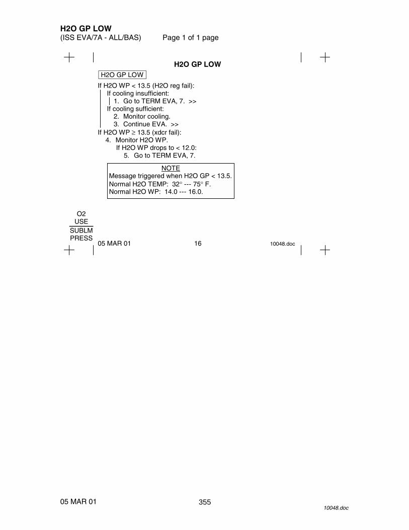
H2O GP LOW (ISS EVA/7A - ALL/BAS) Page 1 of 1 page
05 MAR 01 10048.doc
O2
USE SUBLM PRESS
H2O GP LOW If H2O WP < 13.5 (H2O reg fail):
If cooling insufficient: 1. Go to TERM EVA, 7. >>
If cooling sufficient: 2. Monitor cooling. 3. Continue EVA. >>
If H2O WP ≥ 13.5 (xdcr fail): 4. Monitor H2O WP.
If H2O WP drops to < 12.0: 5. Go to TERM EVA, 7.
05 MAR 01 16 10048.doc
H2O GP LOW
NOTE Message triggered when H2O GP < 13.5. Normal H2O TEMP: 32° --- 75° F. Normal H2O WP: 14.0 --- 16.0.
355

26 APR 01
This Page Intentionally Blank
356
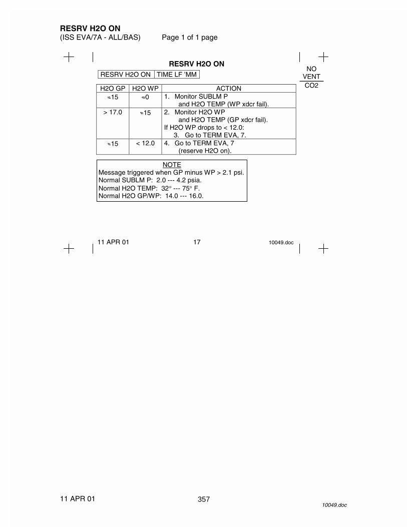
RESRV H2O ON (ISS EVA/7A - ALL/BAS) Page 1 of 1 page
11 APR 01 10049.doc
NO
VENT CO2
RESRV H2O ON
11 APR 01 17 10049.doc
RESRV H2O ON TIME LF ’MM
H2O GP H2O WP ACTION �15 �0 1. Monitor SUBLM P
and H2O TEMP (WP xdcr fail). > 17.0 �15 2. Monitor H2O WP
and H2O TEMP (GP xdcr fail). If H2O WP drops to < 12.0:
3. Go to TERM EVA, 7. �15 < 12.0 4. Go to TERM EVA, 7
(reserve H2O on).
NOTE Message triggered when GP minus WP > 2.1 psi. Normal SUBLM P: 2.0 --- 4.2 psia. Normal H2O TEMP: 32� --- 75� F. Normal H2O GP/WP: 14.0 --- 16.0.
357

26 APR 01
This Page Intentionally Blank
358

NO VENT FLOW (ISS EVA/7A - ALL/BAS) Page 1 of 1 page
05 MAR 01 10050.doc
H2O
GP LO RESRV
H2O
NO VENT FLOW If fan is not running:
1. Cycle FAN sw – OFF,ON If fan restarts:
2. Continue EVA. >> If fan does not start:
3. Helmet purge vlv − op 4. Go to TERM EVA, 7. >>
If fan is running: If RPM < 19.0K:
5. Helmet purge vlv – op 6. Go to TERM EVA, 7. >>
If RPM ≥ 19.0K: 7. Assess helmet CO2 level. 8. Go to CO2 HIGH, 19, step 3.
05 MAR 01 18 10050.doc
NO VENT FLOW
NOTE Message triggered when flow < 3.7 cfm. Normal vent flow: 6 --- 8 cfm.
359

26 APR 01
This Page Intentionally Blank
360

CO2 (ISS EVA/7A - ALL/BAS) Page 1 of 1 page
05 MAR 01 10051.doc
COMM FAIL AIR
CONTM
CO2 1. Minimize physical activity. 2. Assess physical condition then go to step 3 below. 1. √DCM PURGE vlv – cl, √Helmet purge vlv – op If symptoms noted prior to opening purge vlv:
2. Go to TERM EVA, 7. >> If no symptoms noted (or inconclusive):
3. Close/open helmet purge vlv as required to assess physical condition for high CO2.
If symptoms noted: 4. Helmet purge vlv − op 5. Go to TERM EVA, 7. >>
If no symptoms noted: 6. Helmet purge vlv – cl, locked 7. Monitor physical condition and PPCO2. 8. Continue EVA.
05 MAR 01 19 10051.doc
CO2 XX.X MM MONITOR CO2 – PPCO2 > 3.0 MM
CO2 HIGH OPEN PURGE V – PPCO2 > 8.0 MM
NOTE Normal PPCO2: 0.2 --- 0.5 mm
361

26 APR 01
This Page Intentionally Blank
362

COMMUNICATION FAILURE (ISS EVA/7A - ALL/BAS) Page 1 of 1 page
05 MAR 01 10052.doc
NO
VENT CO2
COMMUNICATION FAILURE ALL 1. √Proper config, EMU and ISS (Mode, Volume,
Frequency) Perform following sequence until communication restored:
BOTH If EV crewmember hears intermittent sidetones/ communication or no sidetones:
2. Clear structure to recover communication (signal blockage).
If unresolved: 3. Affected crewmember select ALT(PRI)(notify
MCC-H). IV If IV does not have communication with EV1 and EV2:
4. IV configure for UHF 2(1). ALL If unresolved:
5. Perform coordinated frequency change. If unable to restore minimum of relay communication:
6. Go to TERM EVA, 7.
05 MAR 01 20 10052.doc
363

26 APR 01
This Page Intentionally Blank
364
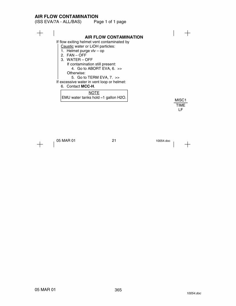
AIR FLOW CONTAMINATION (ISS EVA/7A - ALL/BAS) Page 1 of 1 page
05 MAR 01 10054.doc
MISC1 TIME
LF
AIR FLOW CONTAMINATION If flow exiting helmet vent contaminated by
Caustic water or LiOH particles: 1. Helmet purge vlv – op 2. FAN – OFF 3. WATER – OFF
If contamination still present: 4. Go to ABORT EVA, 6. >>
Otherwise: 5. Go to TERM EVA, 7. >>
If excessive water in vent loop or helmet: 6. Contact MCC-H.
05 MAR 01 21 10054.doc
NOTE EMU water tanks hold ≈1 gallon H2O.
365

26 APR 01
This Page Intentionally Blank
366

MISCELLANEOUS MESSAGES (ISS EVA/7A - ALL/BAS) Page 1 of 2 pages
16 APR 01 10053.doc
COMM FAIL AIR
CONTM
MISCELLANEOUS MESSAGES 1 Built-in tests BITE light illuminated – CWS unreliable, contact MCC-H.
16 APR 01 22 10053.doc
SUIT P EMERG CLOSE PURG V � SUIT P < 3.1
RLF V FAIL STOP DEPRESS – Stop DEPRESS, Contact MCC-H,
SUIT P > 5.7.
LIMITS BAD – Warnings unreliable, monitor status list, continue EVA.
VENT SW FAIL – Vent flow sensor unreliable.
367

MISCELLANEOUS MESSAGES (ISS EVA/7A - ALL/BAS) Page 2 of 2 pages
16 APR 01 10053.doc
IV HATCH
MISCELLANEOUS (Cont)/TIME LF Consumables 1. Contact MCC-H to confirm calculation.
If no communications with MCC-H Go to TERM EVA, 7.
16 APR 01 23 10053.doc
SET O2 EVA SET O2 PRESS SET H2O OFF FAN SW OFF Verify proper configuration. SET PWR SCU O2 IS OFF H2O IS OFF
XX% O2 LF TIME LF ‘MM Triggered with 30 minutes of XX% PWR LF TIME LF ‘MM calculated time remaining for for limiting consumable.
368

IV HATCH LATCH DISCONNECT (ISS EVA/7A - ALL/BAS) Page 1 of 2 pages
26 APR 01 10055.doc
MISC1 TIME
LF
IV HATCH LATCH DISCONNECT IV BAG – EVA RATCHET, 1/2" SOCKET 8" EXT
1. Inspect latches for debris. 2. Remove PIP pin from tension rod. 3. Turn crank handle.
If no rotation: 4. Replace PIP pin. 5. Go back to step 2 with next tension rod.
If free rotation – jammed latch: 6. Remove four captive latch bolts. 7. Remove latch and secure. 8. Hatch � Open
If no rotation with any tension rod: 9. Repeat step 2 for all eight tension rods.
10. Perform steps 6 --- 7 for all eight latches. 11. Hatch � Open
26 APR 01 24 10055.doc
369

IV HATCH LATCH DISCONNECT (ISS EVA/7A - ALL/BAS) Page 2 of 2 pages
26 APR 01 10055.doc
EV HATCH
26 APR 01 25 10055.doc
LATCHES (8) IV HATCH
TENSIONING ROD PIP PIN
CONTINGENCY RELEASE BOLTS (4 PER LATCH)
FOR IV REFERENCE
370

EV HATCH LATCH DISCONNECT (ISS EVA/7A - ALL/BAS) Page 1 of 1 page
11 APR 01 10056.doc
IV HATCH
EV HATCH LATCH DISCONNECT A/L TOOL BOX – EVA RATCHET, 7/16" SOCKET 6" EXT, ADJ
WRENCH CETA TOOL BOX � SM TRASH BAG
1. Remove bolt A, stow in trash bag. 2. Rotate actuator handle.
If no rotation – jammed actuator: 3. Force latches open. 4. Seal hatch with repress and secure.
If free rotation – jammed latch: 5. Locate and remove jam. 6. Reconnect actuator.
11 APR 01 26 10056.doc
PIP pins
371

26 APR 01
This Page Intentionally Blank
372

EV HATCH HINGE DISCONNECT (ISS EVA/7A - ALL/BAS) Page 1 of 1 page
12 MAR 01 10057.doc
SSRMS REL
EV HATCH HINGE DISCONNECT A/L TOOL BOX – ADJ TETHERS
1. Remove hinge PIP pins, as required. 2. Restrain hinge arm(s) and PIP pins clear of opening. 3. Ingress airlock, position hatch for closing. 4. Hatch → close, lock
12 MAR 01 27 10057.doc
PIP pins
373

26 APR 01
This Page Intentionally Blank
374
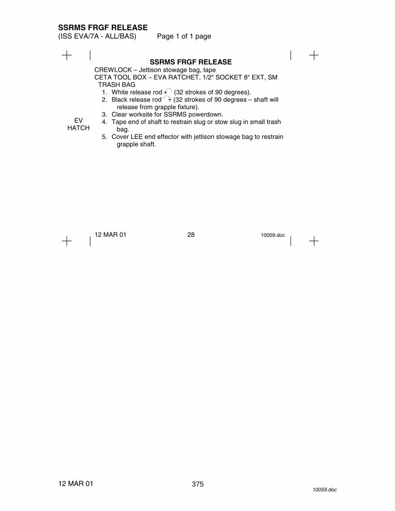
SSRMS FRGF RELEASE (ISS EVA/7A - ALL/BAS) Page 1 of 1 page
12 MAR 01 10059.doc
EV HATCH
SSRMS FRGF RELEASE CREWLOCK – Jettison stowage bag, tape CETA TOOL BOX – EVA RATCHET, 1/2" SOCKET 8" EXT, SM
TRASH BAG 1. White release rod (32 strokes of 90 degrees). 2. Black release rod (32 strokes of 90 degrees – shaft will
release from grapple fixture). 3. Clear worksite for SSRMS powerdown. 4. Tape end of shaft to restrain slug or stow slug in small trash
bag. 5. Cover LEE end effector with jettison stowage bag to restrain
grapple shaft.
12 MAR 01 28 10059.doc
375

26 APR 01
This Page Intentionally Blank
376

SSRMS PDGF RELEASE (ISS EVA/7A - ALL/BAS) Page 1 of 1 page
12 MAR 01 10060.doc
C-LK EGRS C-LK
INGRS
SSRMS PDGF RELEASE CREWLOCK – Jettison stowage bag CETA TOOL BOX − EVA RATCHET, 1/2" SOCKET 8" EXT
1. Rotate shaft release mechanism to hard stop (shaft will release from grapple fixture).
2. Clear worksite for SSRMS powerdown. 3. Cover LEE end effector with jettison stowage bag to restrain
grapple shaft.
12 MAR 01 29 10060.doc
Shaft release mechanism
377

26 APR 01
This Page Intentionally Blank
378

CREWLOCK EGRESS (ISS EVA/7A - ALL/BAS) Page 1 of 1 page
12 MAR 01 10035.doc
SSRMS REL
CREWLOCK EGRESS EV1 1. Thermal cover → open 2. Egress Crewlock. 3. Verify hook locks installed in safety tether hooks on
external D-rings. 4. Safety tether short strap →|← EMU D-ring or extender,
double tether to reel. Unlock reel.
5. Waist tether ←|→ internal Crewlock D-ring, stow on EMU or clear of hatch opening.
EV2 6. Repeat steps 1 --- 5. 7. Thermal cover → close
12 MAR 01 30 10035.doc
379

26 APR 01
This Page Intentionally Blank
380

CREWLOCK INGRESS (ISS EVA/7A - ALL/BAS) Page 1 of 1 page
12 MAR 01 10036.doc
CREWLOCK INGRESS BOTH 1. Complete Tool Inventory. 2. �Tool Boxes closed, latched EV2 3. Waist tether �|� internal Crewlock D-ring 4. Safety tether short strap �|� EMU
Safety tether short strap �|� external hatch handrail. 5. Retract cable slack, lock reel. 6. Ingress Crewlock. EV1 7. Repeat steps 3 --- 6. BOTH 8. WATER � OFF (fwd) 9. Thermal cover � close 10. EV hatch � close and lock 11. Go to {PRE-REPRESS} (DEPRESS/REPRESS Cue
Card).
12 MAR 01 31 10036.doc
381

26 APR 01
This Page Intentionally Blank
382
����������
��� ����� �����
��
��
��
��
��
��
��
�
�
��
��
�
�
383

����������
�
������������������������ ���!��
��
��
��
��
��
��
��
�
�
��
��
�
�
384

EMERGENCY CREWLOCK REPRESS (ISS EVA/7A - ALL/BAS) Page 1 of 1 page
14 FEB 01 10062.doc
NOTE Ignore caution and warning tones and messages.
EV 1. EV Hatch → Close and lock 2. IV Hatch equalization valve → EMER IV 3. EMERGENCY MPEV → OPEN EV 4. √EV Hatch MPEV – CLOSED 5. DCM: WATER → OFF (fwd) 6. IV Hatch → Open 7. Go to {POST EMERGENCY CREWLOCK REPRESS} (SODF: ISS EVA:
EMERGENCY).
385

26 APR 01
This Page Intentionally Blank
386

POST EMERGENCY CREWLOCK REPRESS (ISS EVA/7A - ALL/BAS) Page 1 of 1 page
01 MAR 01 10063.doc
FOR AFFECTED CREWMEMBER DCM 1. PURGE vlv → op (up) 2. O2 ACT → OFF 3. FAN → OFF 4. √Suit P < 0.4 5. Gloves ←|→ EMU 6. Helmet ←|→ HUT DCM 7. SCU →|← DCM UIA 8. PWR EV-1(2) sw → ON
√PWR EV-1(2) EMU LED − √PWR EV-1(2) VOLTS: 18.0 ---19.0
DCM 9. PWR → SCU
FOR UNAFFECTED CREWMEMBER DCM 10. O2 ACT → IV 11. SCU →|← DCM UIA 12. PWR EV-1(2) sw → ON
√PWR EV-1(2) EMU LED − √PWR EV-1(2) VOLTS: 18.0 ---19.0
DCM 13. PWR → SCU E-Lk 14. EMERGENCY MPEV → CLOSE
If single crewmember aborting EVA 15. √MCC-H
387

26 APR 01
This Page Intentionally Blank
388

DCS TREATMENT (ISS EVA/7A - ALL/BAS) Page 1 of 4 pages
18 APR 01 10064.doc
1
EVA terminated to prevent progression to Cuff Class 4. If Cuff 2, affected crewmember will assist other EV with minor worksite cleanup, if possible, to expedite cleanup and then terminate EVA.
2
If estimated time reqd for DCS treatment exceeds Metox canister consumables, a changeout should be performed. If 10 or 12 reqd, minimum treatment is ~3 hr.
3
For Cuff Class 3 only, affected crewmember waiting in Crewlock needs to be in contact with Surgeon via PMC due to severity and potential progression of symptoms.
4
Cuff Class 4 symptoms may be secondary to Type 2 DCS which is a medical emergency. Unstowing the resuscitator enables IV crew to be prepared to administer CPR, if reqd. Because it is critical to repress a Class 4 quickly, this may result in a one crewmember repress.
DCS Signs and Symptoms Associated with Each Cuff Class Defined in Cuff C/L
1
• Determine Cuff Class Cuff Class 1
Cuff Class 2 or 3 (Report to MCC-H)
Cuff Class 4 (Report to MCC-H)
2
• Continue EVA. • If Symptoms resolve
upon REPRESS go to Cuff Class 2, block 5
• Report to Surgeon next PMC.
3
• Terminate EVA (Cuff C/L, 7).
• Unaffected crewmember stow safety tether, perform worksite cleanup and/or ISS safing.
••••√MCC-H for ISS config • Perform INGRESS (Cuff
C/L 43). If terminating for Cuff Class 3 • PMC on GND2 • COMM Mode → HL
ATU4(5) • IV dial GND2
4
NOTE DO NOT perform POST EMERGENCY CREWLOCK REPRESS.
• Abort EVA (Cuff
Checklist, 6) with ingress assist from unaffected crewmember.
• Unaffected crewmember perform ISS safing.
• Unstow resuscitator from
{BASIC LIFE SUPPORT} (SODF: ISS MED: ACLS), then:
Crewmember conscious?
No Yes
5
• Perform PRE-REPRESS (DEPRESS/REPRESS Cue Card).
• Perform REPRESS (DEPRESS/REPRESS Cue Card).
• Remain on SCU. • Unaffected crewmember
perform POST EVA per FLIGHT PLAN, do not perform EVA COMM DECONFIG.
• Perform DCS exam (ISS MED).
• PMC (expect GND2 private).
Does MCC-H require Metox canister changeout?
Yes
No
8
• Perform METOX CANISTER REPLACEMENT.
6
Can crewmember speak in full sentences without respiratory distress?
Yes No
9
• Leave O2 ACT – PRESS for 20 minutes.
• Perform {BTA PREP, BENDS TREATMENT ADAPTER (BTA) INSTALLATION} (SODF: ISS EVA: EMU CONT PROCS).
DCS signs or symptoms resolved?
10
• Leave O2 ACT – PRESS for additional 160 minutes.
• CMO report changes in DCS.
Yes
No
11
3 2 1
16
7
• Perform {POST EVA} (EVA: NOMINAL).
• Treat affected crewmember per {BASIC LIFE SUPPORT} (SODF: ISS MED: ACLS).
•√MCC-H for further action for incapacitated crewmember
4
7
19
4
389

DCS TREATMENT (ISS EVA/7A - ALL/BAS) Page 2 of 4 pages
18 APR 01 10064.doc
11
• Perform {BENDS TREATMENT, ADAPTER (BTA) INSTALLATION UN-SUIT)} (SODF: ISS EVA: EMU CONT PROCS), then:
• Continue BTA Treatment at 6 psi in-suit for 20 minutes.
• CMO report changes in DCS symptoms per DCS exam criteria to surgeon as requested.
DCS signs or symptoms resolved?
9
12
• Continue BTA treatment at 6 psi for 2 hours.
• CMO report changes in DCS symptons per DCS exam cariteria to surgeon as requested.
Yes
No
13
• Perform BTA treatment at 8 psi for 2 hours.
• CMO report changes in DCS symptoms per DCS exam criteria to surgeon as requested.
DCS signs or symptoms resolved?
Yes
No
14
• Leave BTA installed additional 20 minutes.
DCS signs or symptoms resolved?
15
• Leave 02 ACT – PRESS additional 20 minutes.
DCS signs or symptoms resolved?
Yes
No
No
17
16
• Perform {POST EVA} (EVA: NOMINAL), then:
• O2 by PHA mask X 2 hours
•√Surgeon for further DCS treatment
• CMO report changes in DCS symptoms per DCS exam criteria to surgeon every 12 hours.
•√Surgeon for return to IV duty after 24 hours limited activity
•√Surgeon for return to EVA duty
• Go to {BENDS - DECOMPRESSION SICKNESS: DCS} (SODF: ISS MED: A THROUGH B).
Yes
10 17
390
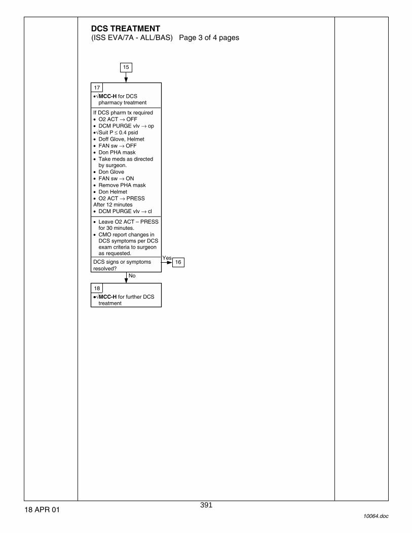
DCS TREATMENT (ISS EVA/7A - ALL/BAS) Page 3 of 4 pages
18 APR 01 10064.doc
17
•√MCC-H for DCS pharmacy treatment
If DCS pharm tx required • O2 ACT → OFF • DCM PURGE vlv → op •√Suit P ≤ 0.4 psid • Doff Glove, Helmet • FAN sw → OFF • Don PHA mask • Take meds as directed
by surgeon. • Don Glove • FAN sw → ON • Remove PHA mask • Don Helmet • O2 ACT → PRESS After 12 minutes • DCM PURGE vlv → cl
• Leave O2 ACT – PRESS
for 30 minutes. • CMO report changes in
DCS symptoms per DCS exam criteria to surgeon as requested.
DCS signs or symptoms resolved?
15
18
••••√MCC-H for further DCS treatment
No
Yes 16
391

DCS TREATMENT (ISS EVA/7A - ALL/BAS) Page 4 of 4 pages
18 APR 01 10064.doc
19
DCS signs or symptoms resolving?
Yes
21
• Perform {BENDS TREATMENT ADAPTER (BTA) INSTALLATION (IN-SUIT)} (SODF: ISS EVA: EMU CONT PROCS).
• Continue treatment at 6 psi for 2 hours.
• Perform DCS exam. • Report changes in DCS
symptoms to surgeon every 15 minutes.
No 20
• Perform BM treatment at 8 psi for hours.
• Perform DCS exam. • Report changes in DCS
symptoms to surgeon every 15 minutes.
DCS signs or symptoms resolving?
22
•√MCC-H for DCS pharmacy treatment
When DCS pharm tx required, • O2 ACT → OFF • DCM PURGE vlv → op •√Suit P ≤ 0.4 psid • Doff Glove, Helmet • FAN sw → OFF • Don PHA mask. • Take meds as directed
by surgeon. • Don Glove • FAN sw → ON • Remove PHA mask, • Don Helmet • O2 ACT → PRESS After 12 minutes • DCM PURGE vlv → CL • Leave O2 ACT – PRESS
for 30 minutes. • CMO report changes in
DCS symptoms per DCS exam criteria to surgeon as requested.
DCS signs or symptoms resolved?
23
• Remain on SCU with O2 ACT – PRESS and BTA installed as determined by MCC-H
25
••••√MCC-H for further action ••••√MCC-H for delayed EMU
doff, stow
No
Yes
6
24
• Perform {POST EVA} (EVA: NOMINAL)
• O2 by PHA mask X 2 hour
•√Surgeon for further DCS treatment
• CMO report changes in DCS symptoms per DCS exam criteria to surgeon every 12 hours.
•√Surgeon for return to IV duty after 24 hours limited activity
•√Surgeon for return to EVA duty
• Go to {BENDS - DECOMPRESSSION SICKNESS: DCS} (SODF: ISS MED: A THROUGH B).
Yes
No
20 22
23
23
392

SAFER RESCUE (ISS EVA/7A - ALL/BAS) Page 1 of 1 page
08 FEB 01 10065.doc
PM 1. Deploy SAFER HCM HCM 2. PWR sw → ON 3. Fly to vehicle.
Monitor GN2 % and PWR %. IV/other EV GCA as required.
***********************************
If no gas flow √MAN ISOL vlv − OP (dn)
*********************************** 4. Tether to nearest structure.
√Connection HCM 5. PWR sw → OFF PM 6. MAN ISOL vlv → CL (up) 7. Tether to available safety tether or other EV crewmember.
√Connection 8. √MCC-H
393

26 APR 01
This Page Intentionally Blank
394