ISPSoft User Manual
801
Industrial Automation Headquarters Delta Electronics, Inc. Taoyuan Technology Center No.18, Xinglong Rd., Taoyuan City, Taoyuan County 33068, Taiwan TEL: 886-3-362-6301 / FAX: 886-3-371-6301 Asia Delta Electronics (Jiangsu) Ltd. Wujiang Plant 3 1688 Jiangxing East Road, Wujiang Economic Development Zone Wujiang City, Jiang Su Province, P.R.C. 215200 TEL: 86-512-6340-3008 / FAX: 86-769-6340-7290 Delta Greentech (China) Co., Ltd. 238 Min-Xia Road, Pudong District, ShangHai, P.R.C. 201209 TEL: 86-21-58635678 / FAX: 86-21-58630003 Delta Electronics (Japan), Inc. Tokyo Office 2-1-14 Minato-ku Shibadaimon, Tokyo 105-0012, Japan TEL: 81-3-5733-1111 / FAX: 81-3-5733-1211 Delta Electronics (Korea), Inc. 1511, Byucksan Digital Valley 6-cha, Gasan-dong, Geumcheon-gu, Seoul, Korea, 153-704 TEL: 82-2-515-5303 / FAX: 82-2-515-5302 Delta Electronics Int’l (S) Pte Ltd. 4 Kaki Bukit Ave 1, #05-05, Singapore 417939 TEL: 65-6747-5155 / FAX: 65-6744-9228 Delta Electronics (India) Pvt. Ltd. Plot No 43 Sector 35, HSIIDC Gurgaon, PIN 122001, Haryana, India TEL : 91-124-4874900 / FAX : 91-124-4874945 Americas Delta Products Corporation (USA) Raleigh Office P.O. Box 12173,5101 Davis Drive, Research Triangle Park, NC 27709, U.S.A. TEL: 1-919-767-3800 / FAX: 1-919-767-8080 Delta Greentech (Brasil) S.A. Sao Paulo Office Rua Itapeva, 26 - 3° andar Edificio Itapeva One-Bela Vista 01332-000-São Paulo-SP-Brazil TEL: 55 11 3568-3855 / FAX: 55 11 3568-3865 Europe Deltronics (The Netherlands) B.V. Eindhoven Office De Witbogt 20, 5652 AG Eindhoven, The Netherlands TEL: 31-40-2592850 / FAX: 31-40-2592851 DVP-4949620-03 *We reserve the right to change the information in this catalogue without prior notice. ISPSoft User Manual www.deltaww.com 2016-05-18 ISPSoft User Manual
Transcript of ISPSoft User Manual

Industrial Automation HeadquartersDelta Electronics, Inc. Taoyuan Technology CenterNo.18, Xinglong Rd., Taoyuan City, Taoyuan County 33068, TaiwanTEL: 886-3-362-6301 / FAX: 886-3-371-6301
AsiaDelta Electronics (Jiangsu) Ltd.Wujiang Plant 31688 Jiangxing East Road, Wujiang Economic Development ZoneWujiang City, Jiang Su Province, P.R.C. 215200TEL: 86-512-6340-3008 / FAX: 86-769-6340-7290
Delta Greentech (China) Co., Ltd.238 Min-Xia Road, Pudong District, ShangHai, P.R.C. 201209TEL: 86-21-58635678 / FAX: 86-21-58630003 Delta Electronics (Japan), Inc.Tokyo Office 2-1-14 Minato-ku Shibadaimon, Tokyo 105-0012, JapanTEL: 81-3-5733-1111 / FAX: 81-3-5733-1211
Delta Electronics (Korea), Inc.1511, Byucksan Digital Valley 6-cha, Gasan-dong, Geumcheon-gu, Seoul, Korea, 153-704TEL: 82-2-515-5303 / FAX: 82-2-515-5302
Delta Electronics Int’l (S) Pte Ltd.4 Kaki Bukit Ave 1, #05-05, Singapore 417939TEL: 65-6747-5155 / FAX: 65-6744-9228
Delta Electronics (India) Pvt. Ltd.Plot No 43 Sector 35, HSIIDC Gurgaon, PIN 122001, Haryana, India TEL : 91-124-4874900 / FAX : 91-124-4874945
AmericasDelta Products Corporation (USA)Raleigh OfficeP.O. Box 12173,5101 Davis Drive, Research Triangle Park, NC 27709, U.S.A.TEL: 1-919-767-3800 / FAX: 1-919-767-8080
Delta Greentech (Brasil) S.A.Sao Paulo OfficeRua Itapeva, 26 - 3° andar Edificio Itapeva One-Bela Vista01332-000-São Paulo-SP-BrazilTEL: 55 11 3568-3855 / FAX: 55 11 3568-3865
EuropeDeltronics (The Netherlands) B.V.Eindhoven OfficeDe Witbogt 20, 5652 AG Eindhoven, The Netherlands TEL: 31-40-2592850 / FAX: 31-40-2592851
DVP-4949620-03
*We reserve the right to change the information in this catalogue without prior notice.
ISPSoft User Manual
www.deltaww.com
2016-05-18
ISP
Soft U
ser M
an
ual

ISPSoft User Manual
Revision History Version Revis ion Date
1s t The f i rs t vers ion was publ ished. 2013/01/18 2 n d Append ix D and Append ix E are added. 2015/03/18
3 r d
1.New contents concern ing AHxxEMC and AS300 ser ies are added in Chapter 3.
2 .New contents concern ing Data Uni t Type are added in Chapter 8.
3. New contents concerning Ax is are added in Chapter 9 .
4.New contents concern ing Cont inuous Funct ion Char ts are added in Chapter 15.
5.New contents concern ing G-Code Ed i tor and E-CAM Ed i tor are added in Chapter 21.
6.New contents concern ing W izard Too l are added in Chapter 22.
7.New contents concern ing AHxxEMC and AS300 ser ies are added in Appendix B.
8 .Append ix D and Append ix E are removed. 9.Update a l l sof tware images.
2016/05/13


i
ISPSoft User Manual Table of Contents
Preface ............................................................................................................... I Chapter 1 Introduction of the Software 1.1 Introduction of ISPSoft and System Requirements .................................. 1-2
1.1.1 Characteristics................................................................................... 1-2 1.1.2 System Requirements ....................................................................... 1-2 1.1.3 Installing ISPSoft ............................................................................... 1-3 1.1.4 Uninstall ISPSoft ............................................................................... 1-5
1.2 Introduction of COMMGR ......................................................................... 1-6 1.2.1 Working Mode of COMMGR ............................................................. 1-6 1.2.2 Installing COMMGR .......................................................................... 1-7 1.2.3 Uninstalling COMMGR .....................................................................1-10
Chapter 2 Starting and Setting 2.1 Guide to Starting ISPSoft and Introduction of the Environment ................ 2-2
2.1.1 First Step of Entering ISPSoft ........................................................... 2-2 2.1.2 Window Title and Status Bar ............................................................. 2-6 2.1.3 Menu Bar ........................................................................................... 2-7 2.1.4 Toolbars ............................................................................................ 2-9 2.1.5 Project Management Area and Message Display Area ....................2-10 2.1.6 Working Area ...................................................................................2-12
2.2 Project Framework ...............................................................................2-14 2.2.1 Single Project and Group of Projects ...............................................2-14 2.2.2 Integration of PMSoft into ISPSoft ....................................................2-15 2.2.3 Managing a Single Project ...............................................................2-16 2.2.4 Managing a Group of Projects ..........................................................2-21 2.2.5 Managing a PMSoft Project through ISPSoft ...................................2-26
2.3 Basic Setting in ISPSoft .......................................................................2-30 2.3.1 System Setting and Environment Setting .........................................2-30 2.3.2 Importing and Exporting Preferences ...............................................2-36
2.4 Communication Setting ........................................................................2-37 2.4.1 Starting/Closing COMMGR ..............................................................2-37 2.4.2 Managing Drivers .............................................................................2-38 2.4.3 Creating a Connection─Creating a Driver ........................................2-39
2.4.3.1 Setting Communication Parameters for RS232……………...…..2-40

i i
2.4.3.2 Setting Communication Parameters for USB (Virtual COM)…...2-41 2.4.3.3 Setting Communication Parameters for DirectLink (USB)……...2-42 2.4.3.4 Setting Communication Parameters for Ethernet……………..…2-43 2.4.3.5 Setting Communication Parameters for DirectLink (Ethernet)…2-44 2.4.3.6 Setting Communication Parameters for a DVP Simulator……...2-45 2.4.3.7 Setting Communication Parameters for a AH Simulator………..2-45
2.4.4 Creating a Connection─Starting/Stopping a Driver ....................... 2-46 2.4.5 Creating a Connection─Configuring/Deleting a Driver .................. 2-47 2.4.6 Creating a Connection Between ISPSoft and COMMGR.............. 2-48 2.4.7 Connecting a PLC and a Communication Port ............................. 2-50 2.4.8 Practical Connection Test ............................................................. 2-52
Chapter 3 Configuring and Setting a PLC System 3.1 Setting Parameters for a DVP Series PLC ................................................ 3-3
3.1.1 System Management Tools for a DVP Series PLC ......................... 3-3 3.1.2 Retentive Range ............................................................................. 3-33.1.3 Connected Information.................................................................... 3-7
3.2 Hardware Configuration Tool for AH and AS Series Modules HWCONFIG…………………………………………………………………......3-7
3.2.1 Introduction of the Environment of HWCONFIG ............................. 3-8 3.2.2 Configuring a Module .................................................................... 3-11
3.2.2.1 Adding a Module ........................................................................ 3-11 3.2.2.2 Assigning Devices to a Module .................................................. 3-16 3.2.2.3 Editing a Comment .................................................................... 3-20 3.2.2.4 Deleting a Module ...................................................................... 3-22 3.2.2.5 Replacing a Module ................................................................... 3-233.2.2.6 Searching for/Replacing a Module ............................................. 3-24 3.2.2.7 Copying/Pasting a Module ......................................................... 3-27 3.2.2.8 Cutting/Pasting a Module ........................................................... 3-29 3.2.2.9 Dragging a Module .................................................................... 3-313.2.2.10 Adding an Extension Rack .......................................................... 3-31 3.2.2.11 Deleting a Rack ........................................................................... 3-33 3.2.2.12 Replacing a Rack ........................................................................ 3-343.2.2.13 Cutting/Copying/Pasting an Extension Rack ............................... 3-353.2.2.14 Dragging an Extension Rack ....................................................... 3-37 3.2.2.15 Rearranging the Input/Output Devices ........................................ 3-37 3.2.2.16 Show/Hide Module Names .......................................................... 3-38
3.2.3 Managing the Version of a Module ............................................... 3-38

i i i
3.3 Setting the Parameters in an AH500 Series CPU Module .......................3-403.3.1 Opening the PLC Parameter Setting Window ...............................3-403.3.2 Setting the Basic CPU Parameters ...............................................3-42
3.3.2.1 CPU: Name ................................................................................3-42 3.3.2.2 CPU: System .............................................................................3-43 3.3.2.3 CPU: Latched Device Range .....................................................3-46
3.3.3 COM Port ......................................................................................3-48 3.3.4 Ethernet - Basic Setups.................................................................3-49 3.3.5 Ethernet - Advance ........................................................................3-50
3.3.5.1 Ethernet - Advance: Filter ..........................................................3-50 3.3.5.2 Ethernet - Advance: NTP ...........................................................3-51 3.3.5.3 Ethernet - Advance: Email..........................................................3-52 3.3.5.4 Ethernet - Advance: Email Trigger .............................................3-53 3.3.5.5 Ethernet - Advance: Email and Trigger Configuration ................3-57 3.3.5.6 Ethernet - Advance: Socket........................................................3-58 3.3.5.7 Ethernet - Advance: Web ...........................................................3-60 3.3.5.8 Ethernet - Advance: Data Exchange ..........................................3-60
3.3.6 Data Exchange Setup - COM ........................................................3-63 3.3.6.1 Data Exchange Setup - COM .....................................................3-65 3.3.6.2 Data Exchange Setup - Ethernet ...............................................3-66
3.4 Setting the Parameters in an AHxxEMC Series CPU Module .................3-67 3.4.1 Opening the PLC Parameter Setting Window ...............................3-67 3.4.2 Options ..........................................................................................3-68
3.4.2.1 Options - ID Info + System .........................................................3-68 3.4.2.2 Option: COM Port Setting ..........................................................3-70 3.4.2.3 Option- Ethernet Setting ............................................................3-71
3.4.3 Data Exchange - COM1, Data Exchange - COM2 and Data Exchange - Ethernet .....................................................................3-71
3.4.3.1 Data Exchange - COM1 and Data Exchange – COM2 ..............3-72 3.4.3.2 Data Exchange - Ethernet ..........................................................3-74
3.5 Setting the Parameters in an AS Series CPU Module .............................3-74 3.5.1 Opening the PLC Parameter Setting Window ...............................3-743.5.2 Options ..........................................................................................3-75
3.5.2.1 Options - System Information .....................................................3-75 3.5.2.2 Options-COM1 Port Setting & COM2 Port Setting .....................3-813.5.2.3 Options - Ethernet Port Basic Setting ........................................3-82 3.5.2.4 Ethernet Port Advance Setting ...................................................3-82 3.5.2.5 Options - Function Card 1 Setting ..............................................3-89

i v
3.5.2.6 Options - Function Card 2 Setting ............................................. 3-90 3.5.3 Configuring AS-Series Remote Modules....................................... 3-91 3.5.4 Data Exchange - COM1, Data Exchange - COM2 and Data
Exchange - Ethernet ..................................................................... 3-93 3.5.4.1 Data Exchange - COM1 and Data Exchange - COM2 ............... 3-94 3.5.4.2 Data Exchange - Ethernet ......................................................... 3-96
3.6 Setting the Parameters in a Module ........................................................ 3-96 3.6.1 Setting the Parameters in AH5x0 and AH5x1 Modules ................. 3-96 3.6.2 Setting the Parameters in AHxxEMC and AS Series Modules .... 3-100 3.6.3 Exporting and Importing the Parameters in a Module ................. 3-1033.6.4 Setting the Parameters in an Intelligent Module ......................... 3-104
3.7 Management of the Parameters in AH and AS Series Hardware and Online Diagnosis ................................................................................... 3-105
3.7.1 Saving and Printing a Hardware Configuration ........................... 3-105 3.7.2 Purchase Order .......................................................................... 3-106 3.7.3 Rack Information List for AH Series ............................................ 3-107 3.7.4 Downloading/Uploading the System Parameters ........................ 3-108 3.7.5 I/O Scan ...................................................................................... 3-109 3.7.6 Online Diagnosis of AH Series .................................................... 3-111
3.7.6.1 Online Mode ............................................................................ 3-112 3.7.6.2 Module Information and Diagnosis .......................................... 3-113 3.7.6.3 Changing the Status of a Module Online ................................. 3-114 3.7.6.4 Monitoring Table ...................................................................... 3-116
3.7.7 Online Diagnosis of AS Series .................................................... 3-116 Online Mode .............................................................................................. 3-117 Module Information and Diagnosis ............................................................ 3-117 Changing the Status of a Module Online.................................................... 3-118
3.8 Setting a RTC........................................................................................ 3-120 3.9 Setting the Memory in a PLC ................................................................ 3-121 Chapter 4 Quick Start 4.1 Quick Start ................................................................................................ 4-2
4.1.1 Example ............................................................................................. 4-2 4.1.2 Hardware ........................................................................................... 4-2 4.1.3 Program ............................................................................................. 4-3
4.2 Procedure for Creating a Project in ISPSoft .............................................. 4-3 4.3 Creating a Project ..................................................................................... 4-4 4.4 Hardware Configuration ............................................................................ 4-5

v
4.4.1 Configuring a Module ........................................................................ 4-5 4.4.2 Setting the Parameters in a CPU Module and a Module ................... 4-6
4.5 Creating a Program .................................................................................. 4-9 4.5.1 Adding a Ladder Diagram ................................................................. 4-9 4.5.2 Basic Editing - Creating a Contact and a Coil .................................. 4-11 4.5.3 Basic Editing - Inserting a Network and Typing an Instruction .........4-14 4.5.4 Basic Editing - Selection of a Network and Operation ......................4-16 4.5.5 Basic Editing - Connecting a Contact in Parallel ..............................4-18 4.5.6 Basic Editing - Editing a Comment ...................................................4-19 4.5.7 Basic Editing - Inserting an Applied Instruction ................................4-20 4.5.8 Basic Editing - Creating a Comparison Contact and Typing a Constant ……………………………………………………………………………..4-22 4.5.9 Writing a Program ............................................................................4-23 4.5.10 Checking and Compiling a Program .................................................4-24
4.6 Testing and Debugging a Program ..........................................................4-24 4.6.1 Creating a Connection ......................................................................4-24 4.6.2 Downloading a Program and Parameters ........................................4-27 4.6.3 Connection Test ...............................................................................4-29
Chapter 5 Program Organization Units and Tasks 5.1 Program Organization Units and Tasks .................................................... 5-2 5.2 Program Organization Units ..................................................................... 5-3
5.2.1 Program Architecture and Types ....................................................... 5-3 5.2.2 POUs in ISPSoft ................................................................................ 5-3
5.3 Tasks ........................................................................................................ 5-5 5.3.1 Managing the Tasks in ISPSoft ......................................................... 5-5 5.3.2 Tasks in the Project Management Area ............................................ 5-5 5.3.3 Executing the POUs Assigned to a Task ........................................... 5-6
5.4 Managing a POU ...................................................................................... 5-9 5.4.1 Creating and Setting a POU .............................................................. 5-9 5.4.2 Enabling a POU................................................................................5-12 5.4.3 Deleting and Copying a POU ...........................................................5-12 5.4.4 Setting and Unlocking a POU Password ..........................................5-14 5.4.5 Exporting a POU of the Program Type .............................................5-15 5.4.6 Importing a POU of the Program Type .............................................5-16 5.4.7 Exporting a POU of the Function Block Type ...................................5-17 5.4.8 Importing a POU of the Function Block Type ...................................5-18
5.5 Managing Tasks ......................................................................................5-19

vi
5.5.1 Setting the Property of a Task and the Condition of an Interrupt ..... 5-21 5.5.2 Assigning a POU to a Task .............................................................. 5-23 5.5.3 Arranging the POUs ......................................................................... 5-24
5.6 Example .................................................................................................. 5-25 5.6.1 Writing a Program by Means of IEC 61131-3................................... 5-25 5.6.2 Example of an Interrupt Subroutine in a DVP Series PLC ............... 5-29 5.6.3 Example of an Interrupt Subroutine in an AH500 Series CPU Module ……………………………………………………………………………..5-35
Chapter 6 Symbols 6.1 Introduction of Symbols ............................................................................. 6-2
6.1.1 Application of Symbols and Creation of Identifiers ............................. 6-2 6.1.2 Symbol Classes ................................................................................. 6-3 6.1.3 Data Types ......................................................................................... 6-3 6.1.4 Assigning a Device to a Symbol and Setting the Initial Value of a
Symbol……………………………………………………………………...6-5 6.1.5 Modifying a Symbol with an Index Register ....................................... 6-6 6.1.6 Bit in a Device Represented by a Symbol (Only for AH/AS Series
CPU Modules) ................................................................................... 6-7 6.2 Managing the Symbols in ISPSoft ............................................................. 6-9
6.2.1 Symbol Tables ................................................................................... 6-9 6.2.2 Adding a Symbol .............................................................................. 6-10 6.2.3 Using a Symbol Whose Data Type is ARRAY or STRING................ 6-14 6.2.4 Modifying a Symbol and Editing a Symbol Table ............................. 6-16 6.2.5 Clearing the Device Addresses Assigned to the Symbols ................ 6-17 6.2.6 Downloading the Initial Values of the Symbols ................................ 6-18 6.2.7 Exporting a Symbol Table ................................................................ 6-19 6.2.8 Importing a Symbol Table ................................................................ 6-20 6.2.9 Arranging the symbols ..................................................................... 6-23 6.2.10 Filtering the Symbols ....................................................................... 6-24 6.2.11 Setting a Range of Devices (Only for DVP Series PLCs) ................ 6-25
6.3 Example .................................................................................................. 6-26 6.3.1 Planning a Symbol Table ................................................................. 6-26 6.3.2 Writing a Program ............................................................................ 6-27
Chapter 7 Function Block and Library 7.1 Knowing Function Blocks .......................................................................... 7-2
7.1.1 Introduction of Function Blocks .......................................................... 7-2

vi i
7.1.2 Characteristics and Advantages of Function Blocks .......................... 7-3 7.2 Structure of the Function Blocks in ISPSoft .............................................. 7-3
7.2.1 En Pin of a Function Block ................................................................ 7-4 7.2.2 Symbols in a Function Block ............................................................. 7-4 7.2.3 Input/Output Pins of a Function Block ............................................... 7-5 7.2.4 Symbol Whose Data Type is POINTER, T_POINTRER, C_POINTER,
or HC_POINTER ............................................................................... 7-8 7.2.5 Function Block Definition and Function Block Instance .................... 7-11 7.2.6 Calling Relation Between Function Blocks .......................................7-15 7.2.7 Assigning a Memory Block to a Function Block ................................7-16
7.3 Using a Function Block ............................................................................7-21 7.3.1 Basic Specifications for the Function Blocks ....................................7-21 7.3.2 Special Pulse Instructions Used in Function Blocks (Only for AH/AS
Series CPU modules) .......................................................................7-22 7.3.3 Monitoring the Program in a Function Block .....................................7-23 7.3.4 Modifying the Program in a Function Block ......................................7-24
7.4 Example ..................................................................................................7-25 7.4.1 Planning a Program ..........................................................................7-25 7.4.2 Creating the Program .......................................................................7-25
7.5 Knowing the Library .................................................................................7-34 7.5.1 Creating the User-defined Library ....................................................7-34 7.5.2 Including the Function Blocks in the User Defined Library ...............7-36 7.5.3 Using Delta Library ...........................................................................7-38
Chapter 8 Data Unit Type 8.1 User-defined Data Type/Data Unit Type ................................................... 8-2 8.2 Structure ................................................................................................... 8-2
8.2.1 Definition of a Structure ..................................................................... 8-2 8.2.2 Creating a Structure .......................................................................... 8-2 8.2.3 Using a Structure Variable ................................................................. 8-4 8.2.4 Applications of Structures .................................................................. 8-5
8.3. Enumeration…………………………………………………………………….8-7 8.3.1 Definition of Enumeration ................................................................. 8-7 8.3.2 Creating an Enumeration .................................................................. 8-7 8.3.3 Using an Enumeration Variable ........................................................ 8-9 8.3.4 Applications of Enumerations ..........................................................8-10
Chapter 9 Axis

vi i i
9.1 Axis………………………………………………………………………….…9-2 9.1.1 The Meaning of Axis .......................................................................... 9-2 9.1.2 Creating a New Axis .......................................................................... 9-2 9.1.3 Main Table and Axis Table under Global Symbols ............................ 9-3
9.2 Axis Parameter and Monitor & Test Run…………………………………..9-4 9.2.1 Axis Parameter .................................................................................. 9-4 9.2.2 Monitor & Test Run ............................................................................ 9-8
Chapter 10 Ladder Diagram 10.1 Introduction of a Ladder Diagram ........................................................ 10-2
10.1.1 Editing Environment ......................................................................... 10-2 10.1.2 Networks in a Ladder Diagram ......................................................... 10-4 10.1.3 Selecting Objects ............................................................................. 10-5
10.2 Creating a Ladder Diagram in ISPSoft ................................................ 10-6 10.2.1 Creating a Contact and a Coil .......................................................... 10-6
10.2.1.1 Inserting a Contact and Changing a Contact Type ..................... 10-6 10.2.1.2 Inserting a Coil and Changing a Coil Type ................................. 10-7
10.2.2 Using Devices, Symbols, and Constants in a Ladder Diagram ........ 10-8 10.2.3 Typing Instructions ........................................................................... 10-9 10.2.4 Inserting Applied Instructions and Function Blocks ........................ 10-10 10.2.5 Creating a Comparison Contact ..................................................... 10-12 10.2.6 Inserting a Block Logic Instruction ................................................. 10-14 10.2.7 Creating Multiple Outputs............................................................... 10-16 10.2.8 Putting a Label ............................................................................... 10-17 10.2.9 Editing a Comment ........................................................................ 10-18 10.2.10 Symbol Mode and Address Mode .................................................. 10-19 10.2.11 Bookmark ....................................................................................... 10-20 10.2.12 Activating/Inactivating a Network ................................................... 10-21
Chapter 11 Function Block Diagram 11.1 Introduction of Function Block Diagrams ............................................. 11-2
11.1.1 Knowing Function Block Diagrams .................................................. 11-2 11.1.2 Editing Environment ......................................................................... 11-2 11.1.3 Networks in a Function Block Diagram ............................................ 11-4 11.1.4 Selecting Objects ............................................................................. 11-5
11.2 Creating a Function Block Diagram in ISPSoft .................................... 11-6 11.2.1 Input Nodes and Output Nodes ........................................................ 11-6 11.2.2 Using Devices, Symbols, and Constants in a Function Block Diagram

i x
……………………………………………………………………………11-10 11.2.3 AND Block and OR Block ...............................................................11-11 11.2.4 Inverse Logic ..................................................................................11-13 11.2.5 Rising edge-triggered Input and Falling edge-triggered Input ........11-15 11.2.6 Setting an Output and Resetting an Output ....................................11-17 11.2.7 Applied Instruction, Comparison Contact, and Function Block .......11-19 11.2.8 Putting a Label ...............................................................................11-23 11.2.9 Comments and Hints ......................................................................11-24 11.2.10 Symbol Mode and Address Mode ..................................................11-26 11.2.11 Bookmark .......................................................................................11-27 11.2.12 Activating/Inactivating a Network....................................................11-28
Chapter 12 Instruction List 12.1 Introduction of Instruction Lists ............................................................12-2
12.1.1 Structure of an Instruction List ..........................................................12-2 12.1.2 Calling a Function Block ...................................................................12-4 12.1.3 Important Points About Instruction Lists ...........................................12-5
12.2 Creating an Instruction List in ISPSoft .................................................12-6 12.2.1 Editing Environment .........................................................................12-6 12.2.2 Creating an Instruction List ...............................................................12-7 12.2.3 Inserting Applied Instructions and Function Blocks ..........................12-8 12.2.4 Bookmark .........................................................................................12-9
12.2.4.1 Adding Bookmarks ...................................................................12-10 12.2.4.2 Removing Bookmarks .............................................................. 12-11 12.2.4.3 Going to a Bookmark ...............................................................12-12
Chapter 13 Structured Texts 13.1 Knowing Structured Texts ....................................................................13-2
13.1.1 Basic Structure of a Structured Text ..............................................13-2 13.1.2 Statement ......................................................................................13-2 13.1.3 Expression ....................................................................................13-3 13.1.4 Operand and Operator ..................................................................13-4 13.1.5 Keyword and Comment .................................................................13-5 13.1.6 Using a Symbol Whose Data Type is ARRAY in a Structured
Text ……………………………………………………………………..13-7 13.1.7 Important Points About Structured Texts .......................................13-7
13.2 Structure of a Statement ......................................................................13-8 13.2.1 Assignment Structure─:= ..............................................................13-8

x
13.2.2 Conditional Structure - IF ............................................................ 13-10 13.2.3 Conditional Structure─CASE ...................................................... 13-12 13.2.4 Loop Structure - REPEAT ........................................................... 13-14 13.2.5 Loop Structure - WHILE .............................................................. 13-15 13.2.6 Loop Structure - FOR .................................................................. 13-16 13.2.7 Applied Instruction Structure ....................................................... 13-17 13.2.8 Function Block Structure ............................................................. 13-18 13.2.9 Blank Statement .......................................................................... 13-19 13.2.10 RETURN Statement .................................................................... 13-20 13.2.11 EXIT Statement ........................................................................... 13-20
13.3 Creating a Structured Text in ISPSoft ................................................ 13-21 13.3.1 Editing Environment .................................................................... 13-21 13.3.2 Creating a Structured Text .......................................................... 13-22 13.3.3 Inserting Applied Instructions and Function Blocks ..................... 13-23 13.3.4 Bookmark .................................................................................... 13-24
13.4 Example of a Structured Text ............................................................ 13-25 13.4.1 Explanation ................................................................................. 13-25 13.4.2 Planning Hardware ..................................................................... 13-25 13.4.3 Planning a Program .................................................................... 13-25 13.4.4 Creating a Program .................................................................... 13-26
Chapter 14 Sequential Function Charts 14.1 Knowing Sequential Function Charts ................................................... 14-2
14.1.1 Structure of a Sequential Function Chart ...................................... 14-2 14.1.2 Principle of a Sequential Function Chart ....................................... 14-2
14.2 Sequential Function Chart is ISPSoft .................................................. 14-4 14.2.1 Steps and Actions ......................................................................... 14-4 14.2.2 Transitions .................................................................................... 14-7 14.2.3 Simultaneous Divergence and Divergence of Sequence Selection
…………………………………………………………………………..14-9 14.2.4 Simultaneous Convergence and Convergence of Sequence Selection
…………………………………………………………………………14-10 14.2.5 Jump ........................................................................................... 14-11 14.2.6 Qualifier of an Action ................................................................... 14-13
14.2.6.1 Qualifier Types ......................................................................... 14-13 14.2.6.2 Important Points About Qualifying an Action ............................ 14-17
14.2.7 Initial Step ................................................................................... 14-18 14.3 Creating a Sequential Function Chart in ISPSoft ............................... 14-19

xi
14.3.1 Editing Environment ....................................................................14-19 14.3.2 Creating and Managing Actions and Transitions .........................14-21 14.3.3 Adding a Step ..............................................................................14-23 14.3.4 Connecting a Transition in Parallel ..............................................14-24 14.3.5 Connecting a Step in Parallel ......................................................14-25 14.3.6 Creating a Simultaneous Divergence and a Convergence of
Sequence Selection ....................................................................14-26 14.3.7 Creating a Divergence of Sequence Selection and a Simultaneous
Convergence ...............................................................................14-27 14.3.8 Inserting a Jump Point ................................................................14-28 14.3.9 Assigning Symbols to the Steps and the Transitions ...................14-29 14.3.10 Specifying an Initial Step .............................................................14-30 14.3.11 Assigning Actions ........................................................................14-30
14.4 Example of a Sequential Function Chart ............................................14-33 14.4.1 Explanation .................................................................................14-33 14.4.2 Planning Hardware ......................................................................14-34 14.4.3 Planning a Program ....................................................................14-34 14.4.4 Creating a Program .....................................................................14-35
Chapter 15 Continuous Function Charts 15.1 Continuous Function Charts (CFC) 2
15.1.1 About Continuous Function Charts ...............................................15-2 15.1.2 Things to Note When Using CFC ..................................................15-2 15.1.3 CFC Programming in ISPSoft .......................................................15-2 15.1.4 CFC Editing Toolbar ......................................................................15-3 15.1.5 Shortcuts for CFC Programing……. ..............................................15-4
15.2 Creating a CFC in ISPSoft……………………………………………..….15-5 15.2.1 Selecting Objects ..........................................................................15-5 15.2.2 Input/Output Nodes and Logic Gates ............................................15-5
15.2.2.1 Inserting Nodes or Gates ...........................................................15-6 15.2.2.2 Add/Delete a Pin ........................................................................15-7
15.2.3 Changing a Pin Type .....................................................................15-8 15.2.4 Connecting objects and Canceling Connections ...........................15-9 15.2.5 Instructions and Function Blocks...................................................15-9
15.2.5.1 Inserting an Instruction ............................................................. 15-11 15.2.5.2 Inserting a Function Block ........................................................15-12
15.2.6 Deleting objects ...........................................................................15-13 15.2.7 Editing Devices or Symbols ........................................................15-15
xi i
15.2.8 Activating/Inactivating an Object ................................................. 15-16 15.2.9 Inserting a Comment .................................................................. 15-16 15.2.10 Changing the Order in Which Objects are Executed ................... 15-18 15.2.11 Displaying/Hiding Information ..................................................... 15-19
Chapter 16 Auxiliary Editing Tools 16.1 Editing Tools and Auxiliary Functions in ISPSoft ................................. 16-2
16.1.1 Changing the PLC Type ................................................................ 16-2 16.1.2 Downloading/Uploading a Project ................................................. 16-2 16.1.3 Find/Replace Function in a Ladder Diagram/Function Block Diagram /
Continuous Function Chart ........................................................... 16-4 16.1.4 Finding/Replacing Text on an Instruction List/in an Structured Text
…………………………………………………………………………..16-6 16.1.5 Finding/Replacing a Step or a Transition in a Sequential Function
Chart (SFC) .................................................................................. 16-8 16.1.6 Finding an Identifier in a Symbol Table ....................................... 16-10 16.1.7 Finding/Replacing a Device or a Symbol in a Project ................. 16-11 16.1.8 Printing Function ......................................................................... 16-12
16.2 Managing Devices and Registers ...................................................... 16-15 16.2.1 Device Comment List for a DVP Series PLC .............................. 16-15 16.2.2 Report on the Devices Used in a DVP Series PLC ..................... 16-17 16.2.3 Managing Devices in an AH/AS Series CPU Module .................. 16-19 16.2.4 Editing Register Memory............................................................. 16-24 16.2.5 Editing Bit Memory ...................................................................... 16-30 16.2.6 Editing the Values in the File Registers in a DVP Series PLC .... 16-34
16.3 Step Positioning ................................................................................. 16-41 16.3.1 Using Step Positioning ................................................................ 16-41
16.4 Program Comparison ........................................................................ 16-41 16.4.1 Introduction to Program Comparison .......................................... 16-41 16.4.2 Compare with File ....................................................................... 16-42 16.4.3 Compare with PLC ...................................................................... 16-43
Chapter 17 Data Backup and Data Restoration 17.1 Online Monitoring Function .................................................................. 17-2
17.1.1 Changing the Operating Status of a PLC ...................................... 17-2 17.1.2 Online Monitoring Function and Environment ............................... 17-2 17.1.3 Changing the States of the X Devices in the Online Mode............ 17-6 17.1.4 Monitoring a Program Online ........................................................ 17-7

xi i i
17.1.5 Device Monitoring Table ..............................................................17-13 17.1.6 Online Editing Function and Online Update Function ..................17-18
17.2 DVP Series Simulator ........................................................................17-19 17.2.1 Creating a DVP Simulator ...........................................................17-19 17.2.2 Starting the DVP Simulator ..........................................................17-20
17.3 Debugging Mode for a DVP Series PLC ............................................17-21 17.3.1 Enabling the Debugging Mode for a DVP Series PLC ................17-21 17.3.2 Adding and Clearing Breakpoints ................................................17-22 17.3.3 Execution of the Program in the Debugging Mode ......................17-22
17.4 AH500 Series Simulator .....................................................................17-24 17.4.1 Creating and Starting an AH Simulator ........................................17-24 17.4.2 Operation Panel of an AH Simulator ...........................................17-25
17.5 Debugging Mode for an AH/AS Series CPU Module .........................17-31 17.5.1 Enabling the Debugging Mode for an AH500 Series CPU Module
…………………………………………………………………………17-31 17.5.2 Adding and Clearing Breakpoints ................................................17-31 17.5.3 Continuous Execution .................................................................17-32 17.5.4 Single-step Execution .................................................................17-32
17.6 Checking the Status of a PLC ............................................................17-34 17.6.1 System Information .....................................................................17-34 17.6.2 System Log (Only for AH/AS Series CPU Modules) ....................17-34
17.7 3D Chart ............................................................................................17-37 17.7.1 Features ......................................................................................17-37 17.7.2 Creating a 3D Chart ....................................................................17-37 17.7.3 Creating a Curve .........................................................................17-38 17.7.4 Display a 3D Chart ......................................................................17-40
Chapter 18 Password Management and Data Protection 18.1 Password Protection Mechanisms Provided by ISPSoft ......................18-2 18.2 Program ID and PLC ID .......................................................................18-3
18.2.1 Setting and Unlocking a Program ID .............................................18-3 18.2.2 Setting and Unlocking a PLC ID ....................................................18-4
18.3 Project Password and PLC Password .................................................18-5 18.3.1 Setting and Unlocking a Project Password ...................................18-5 18.3.2 Setting and Unlocking a PLC Password ........................................18-6 18.3.3 Making a Project Password and a PLC Password Become the
Same..…………………………………………………………………..18-8 18.4 POU Password and Settings Protection ..............................................18-8

xiv
18.5 Subroutine Password .......................................................................... 18-9 18.5.1 Introduction of a Subroutine Passwords ....................................... 18-9 18.5.2 Setting and Unlocking a Subroutine Password ........................... 18-10
18.6 Other Password Protection functions and Data Protection Functions 18-11 18.6.1 Inactivating the Uploading of the Program from a DVP Series PLC
…………………………………………………………………………18-11 18.6.2 Setting Read-only Device Ranges in a DVP Series PLC ............ 18-12 18.6.3 Setting a TC-01 Password Key (for a DVP Series PLC) ............. 18-12
Chapter 19 Network Configuration and Data Exchange 19.1 Network Configuration Tool - NWCONFIG ........................................... 19-3
19.1.1 Introduction of NWCONFIG .......................................................... 19-3 19.1.2 Basic Knowledge .......................................................................... 19-4 19.1.3 Communication Setting in NWCONFIG ........................................ 19-5
19.1.3.1Connection Mechanism in NWCONFIG ...................................... 19-6 19.1.3.2 Setting Communication Parameters .......................................... 19-7
19.1.4 Workflow ....................................................................................... 19-8 19.2 Creating a Network Architecture ........................................................ 19-12
19.2.1 Deploying Nodes ........................................................................ 19-12 19.2.2 Connecting to a Network............................................................. 19-16 19.2.3 Adjusting or Deleting Devices or Networks ................................. 19-21 19.2.4 Setting the Attributes of a Node/Network .................................... 19-24 19.2.5 Hiding/Displaying Devices or Networks ...................................... 19-28 19.2.6 Correct Network Architecture ...................................................... 19-31 19.2.7 Downloading Routing Tables ...................................................... 19-34 19.2.8 Testing Routing ........................................................................... 19-35
19.3 Constructing a PLC Link .................................................................... 19-37 19.3.1 Opening the PLC Link Table Editor Window ............................... 19-38 19.3.2 Designating a Port as a Master Station (Step 1) ......................... 19-39 19.3.3 Setting Communication Parameters (Step 2) .............................. 19-40 19.3.4 Creating a Data Exchange Table (Step 3) ................................... 19-42
19.3.4.1 Introduction of a Data Exchange Table .................................... 19-42 19.3.4.2 Setting a Data Exchange Group .............................................. 19-44 19.3.4.3 Consistency Between a Data Exchange Table and the Network Created in NWCONFIG ........................................................... 19-46
19.3.4.4 Managing a Data Exchange Table ........................................... 19-48 19.3.5 Monitoring a PLC Link ................................................................ 19-49 19.3.6 Important Points About Constructing a PLC Link ........................ 19-53

xv
19.4 Constructing an Ether Link .................................................................19-54 19.4.1 Introduction of an Ether Link .......................................................19-54 19.4.2 Opening the Ether Link Configuration Window ...........................19-5519.4.3 Creating and Managing a Data Exchange Table .........................19-57 19.4.4 Node List and Display Area .........................................................19-60 19.4.5 Start Mode of an Ether Link .........................................................19-6219.4.6 Downloading the Parameters Related to an Ether Link ...............19-6419.4.7 Uploading the Parameters Related to an Ether Link ...................19-6619.4.8 Deleting Asynchronous Device....................................................19-68 19.4.9 Enabling/Disabling the Online Monitoring Function .....................19-69
19.4.9.1 Enabling a Monitoring Function ................................................19-6919.4.9.2 Monitoring Statuses .................................................................19-71 19.4.9.3 Disabling a Monitoring Function ...............................................19-71
19.4.10 Starting/Stopping the Execution of an Ether Link Online .............19-72 19.4.10.1 Starting the Execution of an Ether Link ..................................19-73 19.4.10.2 Stopping the Execution of an Ether Link.................................19-74
19.4.11 Monitoring Table and Error Log ...................................................19-76 19.5 Managing and Applying NWCONFIG.................................................19-77
19.5.1 Saving Parameters and Printing a Network Framework ..............19-77 19.5.2 Downloading Parameters ............................................................19-78
19.5.2.1 Introduction of Parameters .......................................................19-78 19.5.2.2 Description of Downloading Parameters ..................................19-79
19.5.3 Using Routing in ISPSoft .............................................................19-80 Chapter 20 Data Backup and Data Restoration 20.1 Data Backup Memory Cards ................................................................20-2
20.1.1 Introduction of Data Backup Memory Cards .................................20-2 20.1.2 Using a Data Backup Memory Card ..............................................20-2
20.2 Permanent Data Backup ......................................................................20-3 20.3 CARD Utility (for AH/AS Series) ..........................................................20-4
20.3.1 Introduction of CARD Utility ..........................................................20-4 20.3.2 Backup ..........................................................................................20-5 20.3.3 Restoration ....................................................................................20-9
Chapter 21 G-Code Editor and E-CAM Editor 21.1 G-Code Editor………………………………………………………………21-2
21.1.1 About G-Code ...............................................................................21-2 21.1.2 Structure of a G-Code ...................................................................21-2

xv i
21.1.3 Creating a G-Code via the G-Code Editor .................................... 21-3 21.2 E-CAM Editor……………………………………………………………….21-7
21.2.1 About E-CAM (Electronic CAM) .................................................... 21-7 21.2.2 Operation of an Electronic CAM ................................................... 21-7 21.2.3 Creating an E-CAM Chart via the E-CAM Editor ........................... 21-8
Chapter 22 Data Backup and Data Restoration 22.1 Position Planning Table…………………………………………………....22-2
22.1.1 About the Position Planning Table ................................................ 22-2 22.1.2 Setting the Position Planning Table............................................... 22-2 22.1.3 Position Planning Table Simulating ............................................... 22-7 22.1.4 Uploading and Downloading Position Planning Table ................... 22-9 22.1.5 Control Mode - Single-axis Point-to-Point Motion ....................... 22-10 22.1.6 Control Mode - Single-axis Multi-segment Motion ...................... 22-11 22.1.7 Control Mode - 2-axis Linear Interpolation Motion ...................... 22-12 22.1.8 Control Mode - 2-axis Arc Interpolation Motion ........................... 22-12
22.2 Data Tracer………………………..………………………………………22-13 22.2.1 About Data Tracer ....................................................................... 22-13 22.2.2 Opening the Data Tracer Window ............................................... 22-14 22.2.3 Setting Sample Parameters ........................................................ 22-16 22.2.4 Sampling Modes ......................................................................... 22-20 22.2.5 Display Config and Measurement ............................................... 22-21
22.3 Data Logger………………………………………………………………..22-24 22.3.1 About Data Logger ...................................................................... 22-24 22.3.2 Opening the Data Logger Window .............................................. 22-25 22.3.3 Setting Sample Parameters ........................................................ 22-27 22.3.4 Watch and Record ...................................................................... 22-29 22.3.5 Display Config and Measurement ............................................... 22-31
22.4 High Speed Counter…………………………………………………….. 22-34 22.4.1 About High Speed Counter ......................................................... 22-34 22.4.2 Using High Speed Counter ......................................................... 22-35
Appendix A USB Connection A.1 Installing the USB Driver for a PLC .......................................................... A-2 A.2 Creating a Driver Whose Connection Type is USB in COMMGR............. A-5 A.3 Setting the USB Port on a DVP-SX2 Series PLC ..................................... A-7 Appendix B Important Points Related to CPU Modules

xv i i
B.1 Device Addresses in AH/AS Series CPU Modules ................................... B-2 B.1.1 Devices in AH/AS series CPU Modules ............................................ B-2 B.1.2 Manipulating the Bits in the X/Y/D/L Devices .................................... B-3 B.1.3 Updating Input/Output Directly .......................................................... B-4
B.2 Device Resources in AH/AS Series CPU Modules ................................... B-5 B.2.1 AHCPU500-EN/AHCPU500-RS2 ...................................................... B-5 B.2.2 AHCPU510-EN/AHCPU510-RS2 ...................................................... B-6 B.2.3 AHCPU520-EN/AHCPU520-RS2 ...................................................... B-6 B.2.4 AHCPU530-EN/AHCPU530-RS2 ...................................................... B-6 B.2.5 AHCPU511-EN/AHCPU511-RS2 ...................................................... B-7 B.2.6 AHCPU521-EN.................................................................................. B-7 B.2.7 AHCPU531-EN.................................................................................. B-8 B.2.8 AHxxEMC .......................................................................................... B-8 B.2.9 AS300 ............................................................................................... B-9
B.2 Data Exchange Setups ............................................................................. B-9 B.3 Program Compilation and Time for Uploading/Downing ......................... B-10 Appendix C Print Management Tool C.1 Introduction of the Environment ................................................................ C-2 C.2 Introduction of the Setting Area ................................................................ C-3

Preface
I
Preface ISPSoft is Delta’s new generation software development tool for programmable logic controllers. IEC 61131-3, which supports five programming languages and a large number of applied instructions, is adopted. Besides, ISPSoft manages projects by means of integrating tasks. The efficient and convenient development environment that ISPSoft provides enables users to apply PLCs to more complex control systems as well as to small control systems.
About IEC 61131-3 In early days, PLC developers established their own programming languages. These different programming languages were burdens on users. In view of this, IEC 61131-3, which was published by the International Electrotechnical Commission (IEC), appeared. IEC 61131-3 integrated the characteristics of the programming languages. It considered users’ backgrounds and users’ habits, and defined programming language standards that manufacturers and users could follow. The program codes which meet the IEC61131-3 standard are more readable and compatible. The description of IEC 61131-3 is as follows. IEC 61131-3 integrated the programming languages established by PLC developers, and defined
five programming languages for programmable control systems: instruction lists (ILs), structured texts (STs), ladder diagrams (LDs), sequential function charts (SFCs), and function block diagrams (FBDs). Besides, continuous function charts (CFCs), derived from function block diagrams, are also a common PLC programming language.
The concept related to symbols is adopted. Users can replace a device with a symbol. A program is more readable, and the time of assigning devices is saved,
The architecture related to program organization units (POUs) is adopted. A traditional program is divided into several program organization units which can be developed independently. The architecture of a program can be more modular and can be maintained more easily be means of calling functions and function blocks.
Program organization units are managed and organized through the concept related to tasks. The development of programs is upgraded to the management of projects. The large-scale development of programs can be managed more easily.
About the manual The manual aims to introduce the functions of the software. The related concepts are also introduced. The slight variations among different models which are not obstacles to the operation of the software are mentioned briefly. Users have to refer to the related operation manuals or programming manuals for more information. The contents of the manual are oriented towards the introduction of the operation of the software. Users can easily find topics related to the operation of the software in the table of contents, such as setting communication parameters, inserting a contact in a ladder diagram, monitoring devices online, and enabling a simulator. If the topic of a chapter is related to a certain concept, the concept will be introduced in the front part of the chapter. Users who are equipped with basic knowledge, or who want to know the operation of the software can skip this part, and directly refer to the related sections. Besides, if parts of the contents of a chapter are related to the contents of other chapters, the sections to which users have to refer will be noted in the chapter. The brief introduction of the chapters in the manual is as follows. Chapter 1 and chapter 2 introduce the installation of the software, the environment, and the basic
setting. Chapter 3 is about configuring and setting a PLC system. Chapter 4 provides a simple example, and leads users to create a traditional ladder diagram in
ISPSoft in a short time without using the IEC61131-3 architecture. Chapter 5~chapter 8 introduce the concepts related to IEC61131-3, and the ways in which the
concepts are applied to ISPSoft. Chapter 9 introduces the relative concepts of motion control and axis and the ways in which the
concepts are applied to ISPSoft. Chapter 10~chapter 15 introduce ladder diagrams (LDs), function block diagrams (FBDs),
instruction lists (ILs), structured texts (STs), sequential function charts (SFCs), and continuous function charts (CFCs) and the ways in which the concepts are applied to ISPSoft.

ISPSoft User Manual
I I
Chapter 16 introduces the auxiliary tools provided by ISPSoft. Chapter 17 is about monitoring a program, testing a program, and debugging a program through
ISPSoft. Chapter 18 introduces the password setting, and the data protection mechanism in ISPSoft. Chapter 19 is about configuring a network through ISPSoft, and creating a data exchange
mechanism. Chapter 20 is about backing up data and restoring data through ISPSoft. Chapter 21 introduces the tools used commonly in motion control through ISPSoft. Chapter 22 introduces auxiliary tools and wizards provided by ISPSoft for easier programming
and better operation.
Graphic representations The graphic representations used in the manual are listed in the following table.
Graphic representation Description
Clicking the left mouse button
Clicking the right mouse button
Clicking the left mouse button two times in quick succession
Pressing and holding the left mouse button, and then moving the mouse without releasing the button.
Typing with a keyboard
Operating sequence (The graphic representation is used when an operating
sequence is mentioned. For example, and .)
Number used to describe a figure
Point for attention (The item mentioned may be related to damage to equipment, property, or a human body.)
Trademark declaration The products and trademarks which do not belong to Delta Electronics, Inc. belong to the companies which produce and declare them.

1-1
Chapter 1 Introduction of the Software Table of Contents 1.1 Introduction of ISPSoft and System Requirements .................................. 1-2
1.1.1 Characteristics................................................................................... 1-2 1.1.2 System Requirements ....................................................................... 1-2 1.1.3 Installing ISPSoft ............................................................................... 1-3 1.1.4 Uninstall ISPSoft ............................................................................... 1-5
1.2 Introduction of COMMGR ......................................................................... 1-6 1.2.1 Working Mode of COMMGR ............................................................. 1-6 1.2.2 Installing COMMGR .......................................................................... 1-7 1.2.3 Uninstalling COMMGR .....................................................................1-10

ISPSoft User Manual
1-2
1.1 Introduction of ISPSoft and System Requirements ISPSoft is a software development tool for Delta’s new generation programmable logic controllers. IEC 61131-3, which supports five programming languages and a large number of applied instructions, is adopted. In addition to basic programming functions, ISPSoft also contains many auxiliary tools. The multilingual environment and the friendly user interface provide users with a convenient and efficient development environment.
1.1.1 Characteristics
It supports the international standard IEC 61131-3 and a large number of applied instructions. It supports five programming languages. They are ladder diagrams (LDs), sequential function
charts (SFCs), function block diagrams (FBDs), instruction lists (ILs), and structured texts (STs). Users can use more than one programming language in one project.
It supports traditional Chinese, simplified Chinese, and English. The Find and Replace functions can be applied to a present window, or a whole project. It provides a user-defined operating environment. The project management adopts an interface which uses a hierarchical tree structure. Users can develop several models in a group of projects. It provides many convenient functions such as making comments, creating bookmarks,
activating/inactivating networks, managing devices and symbols, simulation, and etc. It supports several types of online operation such as monitoring programs online, editing
programs online, monitoring devices online, debugging programs online, operating/setting a PLC online, and etc.
Users can import and export projects by means of the Import and Export functions. A file (*.dvp) created with WPLSoft can be opened directly, and can be converted into an ISPSoft
format (*.isp). It provides several password setting mechanisms and data protection mechanisms. It supports COMMGR, a new generation communication manager. It supports new generation Delta AH500 series modules. There are three built-in configurations. HWCONFIG: It is used to configure hardware for a system, and manage parameters. NWCONFIG: It is used to configure networks for a PLC system, and manage data exchanges. CARD Utility: Users can backup and restore a system through a management wizard and a
memory card. It provides various solutions for motion control including PLCopen MC function block, G-code
editor, E-CAM editor, positioning planning chart tool and many more.
1.1.2 System Requirements
Before using ISPSoft, users have to make sure that an operating system meets the requirements below.
Item System requirement Operating
system Windows XP / VISTA / 7 / 8 / 10
CPU Pentium 1.5 G or above
Memory 256 MB or above (A memory having a capacity of 512 MB or above is recommended.)
Hard disk drive Capacity : 500 MB or above
CD-ROM drive For installing ISPSoft It is optionally required.
Monitor Resolution: 800×600 pixels or above (Recommended setting: 1024x768/96 dpi )

Chapter 1 Introduc iton of the Software
1-3
Item System requirement Keyboard/Mouse General keyboard/mouse, or device compatible with Windows
Printer Printer with a driver for Windows (It is used to print projects, and is optionally required.)
RS-232 port For connecting to a PLC Users have to select one of them according to the communication interfaces provided by the PLC or the module used. (*1)
USB port For connecting to a PLC
Ethernet port For connecting to a PLC
Communication software COMMGR, a communication manager, must be installed on a computer. (*2)
Models which are supported
AH500 series PLCs/DVP series PLCs (exclusive of DVP-PM series PLCs)/VFD-C2000 series AC motor drives/VFD-C200 series AC motor drives/VFD-CP2000 series AC motor drives /VFD-E series AC motor drives (*3) PLC: all AH series, AS series and DVP series (except DVP-PM series) AC motor drive: VFD series with PLC built-in Text panel: TP series with PLC built-in
*1. ISPSoft supports several ways in which a computer is connected to a PLC. Users have to make sure of the ports and the modes supported by a PLC before a computer is connected to the PLC.
*2. Please refer to section 1.2 for more information about COMMGR. *3. In addition to ISPSoft, users must use PMSoft version 2.05 or above to develop AH10PM-5A and AH20MC-5A. *4. The functions and specifications mentioned above are only applicable to ISPSoft version 2.00 or above. The
older versions may not be equipped with complete functions.
1.1.3 Installing ISPSoft
If an older version of ISPSoft has been installed on a computer, users have to uninstall it before installing ISPSoft. (Pleases refer to section 1.1.4 for more information about uninstalling ISPSoft.) (1) Start a Windows 2000/NT/Me/XP/Vista/7 operating system. Users have to log on to the system
as a system administrator before they install ISPSoft. (2) Put an ISPSoft CD in the CD-ROM drive, or download the installation program from the official
website of Delta http://www.delta.com.tw/ch/index.asp. (Before the installation program downloaded from the website is installed, it needs to be decompressed.)
(3) Click Start, and then click Run… to open the Run window. Specify the path denoting the executable file which is used to install COMMGR in the Open box, and then click OK. Alternatively, users can double-click the icon which is used to install ISPSoft to execute the installation program.

ISPSoft User Manual
1-4
(4) Click Next after the InstallShield Wizard window appears.
(5) Type related information in the User Name box and the Organization box, and then click Next.
(6) Leave the default path unchanged, or click Change… to change the path. Click Next to proceed to the next step.

Chapter 1 Introduc iton of the Software
1-5
(7) Check the installation information, and then click Install.
(8) After ISPSoft is installed, shortcuts to the program will be created on the desktop and the Start menu. Click Finish to complete the installation.
1.1.4 Uninstalling ISPSoft
(1) There are two methods of uninstalling ISPSoft. Method 1: Open the Control Panel window, and click Add or Remove Programs. In the

ISPSoft User Manual
1-6
Currently installed programs box, click ISPSoft x.xx, and then click Remove.
Method 2: Start>Programs>Delta Industrial Automation>PLC>ISPSoft x.xx>Uninstall
(2) After users click Yes, ISPSoft will be removed.
1.2 Introduction of COMMGR COMMGR is a new generation communication management tool developed by Delta Electronics, Inc. in 2011. It functions as a communication bridge between Delta software and hardware. Communication becomes more convenient and more efficient through the management of COMMGR.
1.2.1 Operating Mode of COMMGR Users can create communication parameters which must be set on the management list in COMMGR in advance. The communication parameters which have been created in advance are called drivers. Users can start or stop a driver in COMMGR. If a driver is started, a connection will be created automatically. After the users specify a driver which is started in ISPSoft, a communication will be carried out.

Chapter 1 Introduc iton of the Software
1-7
In addition to ISPSoft, other software communicating with hardware through COMMGR can operate simultaneously. COMMGR automatically manages all communication commands, and makes software connect to hardware.
The COMMGR window and the management list in the COMMGR window are shown below. The drivers which are named by users are displayed in the Name column, parameters related to the drivers are displayed in the Description column, and the statuses of the drivers are displayed in the Status column.
1.2.2 Installing COMMGR
COMMGR is software independent of ISPSoft. It must be installed and uninstalled separately. If an older version of COMMGR has been installed on a computer, users have to uninstall it before installing COMMGR. (Pleases refer to section 1.2.3 for more information about uninstalling COMMGR). (1) Start a Windows 2000/NT/Me/XP/Vista/7 operating system. Users have to log on to the system
as a system administrator before they install COMMGR. (2) Put a COMMGR CD in the CD-ROM drive, or download the installation program from the
official website of Delta http://www.delta.com.tw/ch/index.asp. (Before the installation program downloaded from the website is installed, it needs to be decompressed.)

ISPSoft User Manual
1-8
(3) Click Start, and then click Run… to open the Run window. Specify the path denoting the executable file which is used to install COMMGR in the Open box, and then click OK. Alternatively, users can double-click the icon which is used to install COMMGR to execute the installation program.
(4) Click Next after the InstallShield Wizard window appears.

Chapter 1 Introduc iton of the Software
1-9
(5) Type information in the User Name box and the Organization box, and then click Next.
(6) Check the installation information, and then click Install.
(7) After COMMGR is installed, a shortcut to the program will be created on the Start menu. Click Finish to complete the installation.

ISPSoft User Manual
1-10
1.2.3 Uninstalling COMMGR
(1) There are two methods of uninstalling COMMGR. Method 1: Open the Control Panel window, and click Add or Remove Programs. In the
Currently installed programs box, click COMMGR x.xx.xx, and then click Remove.
Method 2: Start>Programs>Delta Industrial
Automation>Communication>COMMGR>Uninstall
(2) After users click Yes, COMMGR will be removed.

2-1
Chapter 2 Starting and Setting Table of Contents 2.1 Guide to Starting ISPSoft and Introduction of the Environment ............ 2-2
2.1.1 First Step of Entering ISPSoft ............................................................ 2-2 2.1.2 Window Title and Status Bar ............................................................. 2-6 2.1.3 Menu Bar ........................................................................................... 2-7 2.1.4 Toolbars ............................................................................................. 2-9 2.1.5 Project Management Area and Message Display Area ....................2-10 2.1.6 Working Area ....................................................................................2-12
2.2 Project Framework ...............................................................................2-14 2.2.1 Single Project and Group of Projects ...............................................2-14 2.2.2 Integration of PMSoft into ISPSoft ....................................................2-15 2.2.3 Managing a Single Project ...............................................................2-16 2.2.4 Managing a Group of Projects ..........................................................2-21 2.2.5 Managing a PMSoft Project through ISPSoft....................................2-26
2.3 Basic Setting in ISPSoft .......................................................................2-30 2.3.1 System Setting and Environment Setting .........................................2-30 2.3.2 Importing and Exporting Preferences ...............................................2-36
2.4 Communication Setting ........................................................................2-37 2.4.1 Starting/Closing COMMGR ..............................................................2-37 2.4.2 Managing Drivers .............................................................................2-38 2.4.3 Creating a Connection─Creating a Driver ........................................2-39
2.4.3.1 Setting Communication Parameters for RS232 .....................2-40 2.4.3.2 Setting Communication Parameters for USB (Virtual COM) ..2-41 2.4.3.3 Setting Communication Parameters for DirectLink (USB) .....2-42 2.4.3.4 Setting Communication Parameters for Ethernet ..................2-43 2.4.3.5 Setting Communication Parameters for DirectLink (Ethernet)
..............................................................................................2-44 2.4.3.6 Setting Communication Parameters for a DVP Simulator ......2-45 2.4.3.7 Setting Communication Parameters for a AH Simulator ........2-45
2.4.4 Creating a Connection─Starting/Stopping a Driver ...........................2-46 2.4.5 Creating a Connection─Configuring/Deleting a Driver .....................2-47 2.4.6 Creating a Connection Between ISPSoft and COMMGR .................2-48 2.4.7 Connecting a PLC and a Communication Port .................................2-50 2.4.8 Practical Connection Test .................................................................2-52

ISPSoft User Manual
2-2
2.1 Guide to Starting ISPSoft and Introduction of the Environment
2.1.1 First Step of Entering ISPSoft
After ISPSoft is installed, shortcuts to the program are created on the desktop and the Start menu. Users can click the shortcut on the Start menu or double-click the shortcut on the desktop to start ISPSfot. Besides, several ISPSoft windows are allowed. Users can start ISPSoft again in the same way.
After the welcome screen disappears, the Delta ISPSoft window appears. There are basic functions available to users.
After on the toolbar is clicked, a new project is created.

Chapter 2 Star t ing and Sett ing
2-3
In the Create a New Project window, type a project name in the Project Name box and a path in the Drive/Path box, and select a controller type and a PLC type in the Controller Type and the PLC Type drop-down lists. After users click Properties…, they can give a description of this project. Finally, click OK.
After the project is created successfully, a project management area will appear at the left side of the main screen. The relation between the items listed in the project management area is represented by a hierarchical tree structure. If the project management area does not appear, users can click Workspace on the View menu, or click on the toolbar. Besides, a message display area will appear if users click Output Window on the View menu or click on the toolbar.

ISPSoft User Manual
2-4
After the project is created, the main working area is blank. If users want to write a program, they can right-click Programs in the project management area and click New….
In the Create Program window, users can type a program name in the POU Name box, and select a programming language in the Language section. The other default values are retained, and will be introduced in section 5.4.
After a program organization unit is created successfully, an item will appear under Programs in the project management area, and a program editing window will appear in the main working area.

Chapter 2 Star t ing and Sett ing
2-5
The main screen of ISPSoft is shown below.
Window title: It displays a project name and a program title.
Menu bar: There are eight menus.
Toolbar: There are five toolbars.
Project management area: It adopts an interface which uses a hierarchical tree structure.
Message display area: The messages related to the compiling of a program and search for data in a project are displayed in this area.
Status bar: Information about the editing of a program and connection is displayed.
Working area: A program editing area, a symbol table, a device table, and etc. are displayed in this area.
Delta Library: The contents of Delta library and user-defined library are displayed in this area.
When using ISPSoft, users can click an item on the Help menu to get help.

ISPSoft User Manual
2-6
Item Description
About… Users can get the information about the version of the software, and the date when the software is released.
ISPSoft User Index Users can get the usage of the software. (Alternatively, the users can click on the file toolbar to get the usage of the software.)
PLC Instruction and Special Registers Reference
Users can get the information about instructions and registers. If users click an instruction in the program editing area and press F1 on the keyboard, they can get the information about the instruction.
Version History Users can get the information about the version history of the software, and the changelog.
2.1.2 Window Title and Status Bar
After a project is created successfully, the window title displays its project name and its program title. The format is project name [program title]. If users do not set a program title, the window title will only display a project name. Besides, if users want to view the information about a program title, they can click Edit on the MY_Project window and select the Project Properties.
The status bar at the bottom of a window displays all kinds of working states, including an editing mode (insertion/replacement), a network which is edited presently, a scan time, the size of a program which is written/the size of a program which can be written, a connection status, the status of a PLC, communication parameters, and a PLC model.

Chapter 2 Star t ing and Sett ing
2-7
2.1.3 Menu Bar
There are eight menus in the menu bar. The items on the menus vary with editing work carried out, and a model selected. A brief introduction of the menu bar is presented here, and a more detailed introduction of the menu bar will be presented in the following chapters.
File: It provides the function of accessing projects.
Edit: It provides the function of editing a project.
View: It provides the function of viewing information about a project, and the function of setting a
work environment.
Insertion/Replacement mode
Network which is edited presently
Scan time
Size of a program which is written/Size of a program which can be written
Connection status
Status of a PLC
Communication parameters
PLC model

ISPSoft User Manual
2-8
Compile: It provides the function of checking syntax, and the function of compiling a program into
an execution code.
PLC: It provides the function of operating or setting a PLC through ISPSoft.
Tools: It provides some convenient functions.
Window: It provides the function of managing windows in the working area.
Help: It provides help to users.

Chapter 2 Star t ing and Sett ing
2-9
2.1.4 Toolbars
There are five toolbars. The icons on the toolbars also vary with editing work carried out, and a model selected. Besides, if a mouse cursor is moved to an icon and stays there for a while, the function represented by the icon and the shortcut to the function will be displayed. Users can select a toolbar which they want ISPSoft to display or hide by clicking Toolbar on the View menu.
File toolbar: It provides the functions related to processing a project.
Editing toolbar: It provides the functions related to editing work.
PLC toolbar: It provides the functions related to operating a PLC.
Debugging toolbar: It provides the functions related to debugging a program. The icons on the toolbar vary with a model selected.
AH/AS series: DVP series:
Programming toolbar: It provides the functions related to editing a program. The icons ton the toolbar vary with a programming language selected.
LD: FBD: IL: ST: SFC:

ISPSoft User Manual
2-10
2.1.5 Project Management Area and Message Display Area
The contents of the project management area are items related to project development. The project management area adopts an interface which uses a hierarchical tree structure. The contents of the project management area include a hardware configurator, information about devices and applied instructions, symbols created by users, programs, tables of devices monitored, and etc. The items listed in the project management area vary with a model selected. The project management area appears at the left side of the main screen. If users want to close the area, they can click in the upper right corner of the area. They can click on the toolbar, or click Workspace on the View menu to open or close the project management area. Besides, after users right-click an item in the project management area, a context menu will appear. The available choices on the context menu are actions related to the item.
The message display area is composed of the Compile Message page and the Find Result page. Users can switch between the pages by clicking the tabs under the message display area. The Compile Message page shows a result or message related to the compiling of a program or the checking of syntax, and the Find Result page shows a result related to the search for data in a project. The message display area appears at the bottom of the main screen. Users can click on the toolbar, or click Output Window on the View menu to open or close the message display area. If users want to close the area, they can click in the upper right corner of the area.
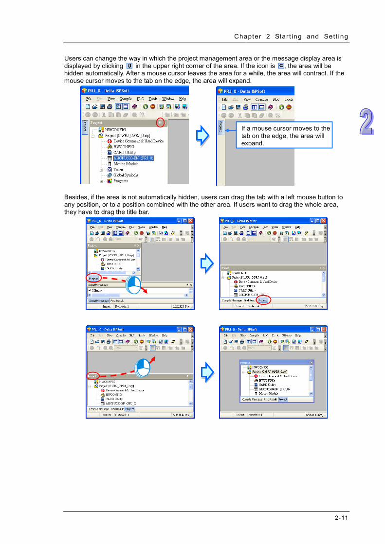
Chapter 2 Star t ing and Sett ing
2-11
Users can change the way in which the project management area or the message display area is displayed by clicking in the upper right corner of the area. If the icon is , the area will be hidden automatically. After a mouse cursor leaves the area for a while, the area will contract. If the mouse cursor moves to the tab on the edge, the area will expand.
Besides, if the area is not automatically hidden, users can drag the tab with a left mouse button to any position, or to a position combined with the other area. If users want to drag the whole area, they have to drag the title bar.
If a mouse cursor moves to the tab on the edge, the area will expand.

ISPSoft User Manual
2-12
2.1.6 Working Area
All windows are displayed in this area. If a window is maximized or minimized, it is maximized or minimized in this area. When a window is maximized, the status buttons for the window appear at the right side of the menu bar. Display of windows
A window is maximized.
Users can manage windows and switch among windows through the choices on the Window menu.
Selecting an item to switch among the windows

Chapter 2 Star t ing and Sett ing
2-13
Cascade: After the item is clicked, all windows will stack on top of each other, and the present window will in the front of the screen.
Tile Vertically: Choosing Tile Vertically will cause windows to tile horizontally but take on a
vertical shape. The present window will be at the leftmost side.
Tile Horizontally: Choosing Tile Horizontally will cause windows to tile vertically but take on a
horizontal shape. The present window will be the topmost window.

ISPSoft User Manual
2-14
2.2 Project Framework
2.2.1 Single Project and Group of Projects There are two types of project frameworks. They are described below. A single project
A single project is a most basic type of project. Only one model is developed in a single project. In other word, a single project is applied to a single model. The filename extension for a project is .isp.
A group of projects
If several devices are connected on a network, users can create a group of single projects for the devices without restriction. Besides, the number of projects which can be created is unlimited. Users can make projects according to practical application, and they can carry out network configuration for the devices in a group of projects through NWCONFIG rapidly and easily. The filename extension for a group of projects is .pri, and the filename extension for every project in the group is .isp. The isp files are in the folders whose names are the same as the project names. Besides, users can import a single project which was created previously to a group.
*. Please refer to chapter 19 for more information about NWCONFIG.

Chapter 2 Star t ing and Sett ing
2-15
2.2.2 Integration of PMSoft into ISPSoft
The AH500 series modules include two motion control modules. They are AH10PM-5A and AH20MC-5A. Users can write a program for a motion control module by means of PMSoft, software developed by Delta Electronics, Inc.. Please refer to PMSoft User Manual for more information about usage. PMSoft is integrated into ISPSoft. Users can create a PMSoft project in ISPSoft, and configure hardware through HWCONFIG. Whether a project is a single project for an AH500 series module or a project for an AH500 series module created in a group, users can create a PMSoft in the project. The number of PMSoft projects which can be created is unlimited. However, whether a PMSoft project is executed or not depends on hardware configuration carried out through HWCONFIG. Please refer to section 2.2.5 for more information.
The filename extension for a PMSoft projects is .ppm. A PMSoft project and a single project in which the PMSoft project is created are saved in the same folder. Users can import a PMSoft project which was created previously to an ISPSoft project.
*1. To create a PMSoft project, PMSoft version 2.05 or above is used. A PMSoft project can not be created in an
ISPSoft project for a DVP series PLC. *2. A PMSoft project which is imported must be a file created with PMSoft version 2.05 or above, and a project for a
DVP-PM series PLC is not supported. *3. Please refer to chapter 3 for more information about HWCONFIG.

ISPSoft User Manual
2-16
2.2.3 Managing a Single Project Creating a single project
User can click the File menu, point to New, and click New to create a new project. They can also create a new project by clicking on the toolbar.
In the Create a New Project window, type a project name in the Project Name box and a path in the Drive/Path box, and select a controller type and a PLC type in the Controller Type and the PLC Type drop-down lists. After users click Properties…, they can give a description of this project. Finally, click OK.

Chapter 2 Star t ing and Sett ing
2-17
After a project is created successfully, the window title displays its project name and its program title. The format is project name [program title]. If users do not set a program title, the window title will only display a project name. Besides, if users want to view the information about a program title, they can click Edit on the MY_Project window and select the Project Properties.
Users can see a path denoting a file and a model selected in the project management area. If a project created is a project for an AH/AS series module, a name in parentheses will be attached to the model selected, and the name will be the project name. The name can be changed through HWCONFIG. Please refer to section 3.3.2.1 for more information.
*. If a project created is a project for an AH/AS series module, a name in parentheses will be attached to the model
selected. If a project created is a project for a DVP series PLC, no name will be attached to the model selected. Users can identify a device by means of the name attached to it. When several devices are connected on a network, users can check whether a device connected to the computer is the device they expect by means of the name attached to the device.
Saving a project
After a project is created, the file denoted by a path does not actually exist. The file will exist after users save the file. A file is saved in the following way. Users can click the File menu, and click Save to save a file. They can also save a file by clicking
on the toolbar.
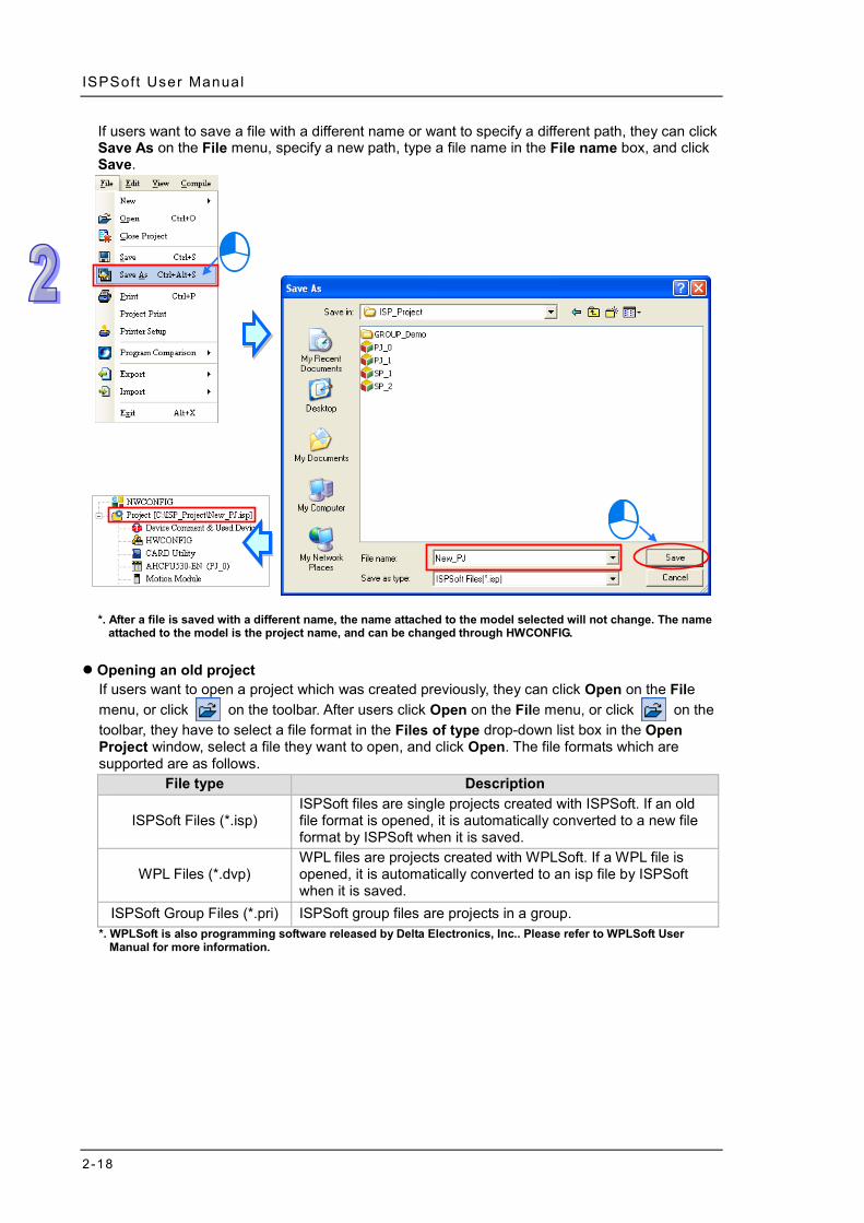
ISPSoft User Manual
2-18
If users want to save a file with a different name or want to specify a different path, they can click Save As on the File menu, specify a new path, type a file name in the File name box, and click Save.
*. After a file is saved with a different name, the name attached to the model selected will not change. The name
attached to the model is the project name, and can be changed through HWCONFIG. Opening an old project
If users want to open a project which was created previously, they can click Open on the File menu, or click on the toolbar. After users click Open on the File menu, or click on the toolbar, they have to select a file format in the Files of type drop-down list box in the Open Project window, select a file they want to open, and click Open. The file formats which are supported are as follows.
File type Description
ISPSoft Files (*.isp) ISPSoft files are single projects created with ISPSoft. If an old file format is opened, it is automatically converted to a new file format by ISPSoft when it is saved.
WPL Files (*.dvp) WPL files are projects created with WPLSoft. If a WPL file is opened, it is automatically converted to an isp file by ISPSoft when it is saved.
ISPSoft Group Files (*.pri) ISPSoft group files are projects in a group. *. WPLSoft is also programming software released by Delta Electronics, Inc.. Please refer to WPLSoft User
Manual for more information.

Chapter 2 Star t ing and Sett ing
2-19

ISPSoft User Manual
2-20
Besides, users can select a project recently edited on the File menu.
Closing a project
After the editing of a project is complete, users can click Close Project on the File menu to close the project. If the project has not been saved, a window inquiring whether users want to save the project appears.
Additional remark If users do not close ISPSoft before they close a project, the project will be opened automatically next time ISPSoft is started. (Users can decide whether a project will be automatically opened. Please refer to section 2.3.1 for more information.)

Chapter 2 Star t ing and Sett ing
2-21
2.2.4 Managing a Group of Projects Creating a group of projects
Click the File menu, point to New, point to Group Project, and click New Group Project.
If users want to create a group of projects, they have to create the first single project in the group. In the Create a New Project window, type a project name in the Project Name box and a path in the Drive/Path box, and select a controller type and a PLC type in the Controller Type and the PLC Type drop-down lists. After users click Properties…, they can give a description of this project. Besides, they have to type a group name in the Group Project Name box. Finally, click OK.
After the first single project is created, the information related to the first single project will be displayed in the project management area. Owing to the fact that there is only one project in the group, it is displayed in a way in which a single project is displayed, and it can be saved in a way in which a single project is saved. The only difference between the project in the group and a single project is that users can not click Save As on the File menu for the project in the group.

ISPSoft User Manual
2-22
Adding a single project to a group Users can click the File menu, point to New, point to Group Project, and click New to Group Project to add a new single project to the group. They can also right-click a project in the project management area and click New to Group Project to add a new single project to the group.
Owing to the fact that one project is edited at a time, a project being edited will be closed if a new project is added to the group. If the project being edited has not been saved, a window inquiring whether users want to save the project appears. In the Create a New Project window, users can type a project name in the Project Name box, and select a PLC in the PLC Type drop-down list box. Besides, after users click Properties…, they can give a description of the project. However, users can not specify a path.

Chapter 2 Star t ing and Sett ing
2-23
Activating a project One project is edited at a time. If users want to edit another project, they can double-click a project they want to edit, or they can right-click a project they want to edit and click Active Project.
After a project is activated, the window title will be composed of the name of the project and the program title of the project. The projects which are not activated will become gray in the project management area.

ISPSoft User Manual
2-24
Importing a single project to a group If an isp file is not created in a group, users can import it into the group. If users want to import a single project, they can right-click a project in the project management area, point to Group Project on the context menu, click Add to Group Project, and select a single project they want to import in the Open Project window.
The file which can be imported is an isp file. After a project is imported into a group, the project will be copied and saved in a folder in which the group is saved, and the original project is still saved in the original folder.

Chapter 2 Star t ing and Sett ing
2-25
Removing a single project from a group If users want to remove a single project from a group, they can right-click a single project they want to remove in the project management area and click Remove from Group Project. However, if there is only one project in a group, the project can not be removed.
After a project is removed from a group, it will be removed from the list of projects in the project management area, and will not be deleted from the original folder in which it is saved. If users want to add the project to the group later, they can import it into the group.

ISPSoft User Manual
2-26
Opening a group of projects If users want to open a group of projects created previously, they can click Open on the File menu, or on the toolbar, select ISPSoft Group Files (*.pri) in the Files of type drop-down list box in the Open Project window, select a file they want to open, and click Open.
If a project in a group which is opened is marked with a red cross, the project saved in the folder in which the group is saved is abnormal. The project may be deleted or saved in a different folder, or the filename of the project is changed.
Closing a group of projects
Users can click Close Project on the File menu to close a project which is being edited. Other projects which are not activated can still be activated. If users want to close a whole group of projects, they can click Close All Project on the File menu.
2.2.5 Managing a PMSoft Project through ISPSoft
The AH500 series modules include two motion control modules. They are AH10PM-5A and AH20MC-5A. Users can write a program for a motion control module by means of PMSoft, software

Chapter 2 Star t ing and Sett ing
2-27
developed by Delta Electronics, Inc.. If a project is created for an AH500 series module, the Motion Module item will appear in the project management area. If PMSoft version 2.05 or above is installed on a computer, users can manage PMSoft projects by means of the Motion Module item. Creating a new PMSoft project
If users want to create a PMSoft project with ISPSoft, they have to right-click Motion Module in the project management area and click New Motion Module.
In the New Motion Module window, type a file name in the File Name box, select a model in the Type drop-down list box, and select a rack number and a slot number in the Rack No. and Slot No. drop-down lists according to the hardware configuration carried out through HWCONFIG. Every slot number corresponds to a PMSoft project. If a slot number is not set, or if users want to change a slot number later, users can select Undefined in the Slot No. drop-down list box. After the setting is complete, users can click OK.
*. Please refer to chapter 3 for more information about HWCONFIG.

ISPSoft User Manual
2-28
Developing a PMSoft project If users want to edit a project for a motion control module which has been created, they have to double-click the project to start PMSoft. The users can write a program for the motion control module in PMSoft.
However, if users do not specify a slot for a motion control module, they are not allowed to edit the project for the motion control module.
*. Please refer to PMSoft User Manual for more information about the usage of PMSoft. If PMSoft is started
through ISPSoft, users can not create a new file, open an old file, and change a model in PMSoft. Besides, users must save a program written in PMSoft by clicking Save on the File menu in PMSoft.
Deleting a PMSoft project
If users want to delete a project for a motion control module, they can right-click a project they want to delete in the project management area and click Remove Motion Module. After a project for a motion control module is deleted, it will be removed from the list of projects in the project management area, and will not be deleted from the original folder in which it is saved.

Chapter 2 Star t ing and Sett ing
2-29
Importing a PMSoft project If users want to import a PMSoft project (a ppm file) which was created previously to an ISPSoft project, they have to right-click Motion Module in the project management area and click Add Existed Motion Module.
Users have to select a PMSoft project which they want to import in the Open Project window, and click Open. The slot number in a PMSoft project imported is undefined.
After a PMSoft project is imported into an ISPSoft project, the PMSoft project will be copied and saved in a folder in which the ISPSoft project is saved, and the original PMSoft project is still saved in the original folder. Besides, a PMSoft project which is imported must be a file created with PMSoft version 2.05 or above, and a project for a DVP-PM series PLC is not supported.
Changing a slot number If users want to change the slot number in a project, they have to right-click the project and click Change Slot No..

ISPSoft User Manual
2-30
Users have to select a slot number in the Slot No. drop-down list box in the New Motion Module window. They can not select a slot number which has been selected. Finally, click OK.
2.3 Basic Setting in ISPSoft
2.3.1 System Setting and Environment Setting Users can select a language in the Language drop-down list box on the Tools menu.

Chapter 2 Star t ing and Sett ing
2-31
After users click Options… on the Tools menu, the Options window will appear. The users can click the items at the left side of the window, and the tabs at the top of the window.
System setting─Project Setting
If this item is selected, a project which was edited last and which was not closed will be
opened automatically whenever ISPSoft is started. If this item is selected, a project which is being edited is backed up as a temporary file every
specific period of time. (Users can select a time interval in the Minutes drop-down list box.) If

ISPSoft User Manual
2-32
ISPSoft is not closed normally, users will be asked whether they want to load the last backup project next time the project is opened.
If this item is selected, a project which is being edited is saved automatically before the program in the project is compiled.
If this item is selected, different symbols can refer to the same device. If a project is created for an AH/AS series module, the item cannot be selected.
System setting─Workspace
Users can select a font for the project management area.
Users can select a background color of the project management area.
Users can preview changes here.
System setting─Output Window
Users can preview changes here.
Users can select a font for the message display area.
Users can select a background color of the message display area.

Chapter 2 Star t ing and Sett ing
2-33
System setting─Symbol Table
Users can preview changes here.
Users have to select an item in the Item section, and then select a font in the Text section.
If this item is selected, the Add Symbol window will close automatically after a symbol is declared.
If this item is selected, the Add Symbol window will appear automatically after users type an undefined symbol in a ladder diagram (LD), function block diagram (FBD), or a sequential function chart (SFC), and press Enter on the keyboard.
If a symbol is cut/copied, the symbol pasted will include a comment.
If this item is selected, the Symbol/Address mode can be selected in the icon tool bar.
If this item is selected, input the variables in the program, the system will list all the set items for the variable and users can use the mouse or key board to select from the list.
【】OR【】

ISPSoft User Manual
2-34
Editor─[LADDER] [FBD]
Users have to select an item here.
Users can preview changes here.
Users can select a type and a color.
After the mouse cursor stays at an object for a while, the hints users select in the Show Symbol Hint section will appear.
Users can set the widths of blocks. The setting will affect the lengths of symbols in blocks. Editor─[SFC]
Users have to select an item here.
Users can select a font here.
Users can preview changes here.

Chapter 2 Star t ing and Sett ing
2-35
Editor─[IL] [ST]
Users have to select an item here.
Users can select display styles here.
Users can preview changes here.
Editor─[CFC]
Select the item for setting in this area.
The setting values are listed in this area.
The setting result can be seen in the preview.
After Default is clicked, all setting values will become default values. After users complete all setting, they can click OK to apply changes.

ISPSoft User Manual
2-36
*. If several ISPSoft windows are opened, users can set them differently. However, only the environment setting of
an ISPSoft window which is closed last is memorized. As a result, the setting values in an ISPSoft window which is closed last will be applied next time ISPSoft is started.
2.3.2 Importing and Exporting Preferences
Users can export and import environment setting through the functions provided by ISPSOft. Exporting preferences
Click the Tools menu, point to Export, click Preferences, type a file name in the File name box in the Exporting User Preference window, and click Save.
Importing preferences Click the Tools menu, point to Import, click Preferences, select a file in the Import User Preference window, and click Open.

Chapter 2 Star t ing and Sett ing
2-37
Additional remark Owing to the fact that environment parameters vary with versions of ISPSoft, environment setting imported is not necessarily applicable. If users do not know which version of ISPSoft is a preference file (*.pfs) is exported from, they can check whether the contents of the file meets their expectation after the file is imported.
2.4 Communication Setting The communication between ISPSoft and a Delta PLC is shown below. The communication manager COMMGR is a communication interface between ISPSoft and a PLC. This section introduces how to create a connection between ISPSoft and a PLC, and complete a basic test.
*1. Please refer to section 1.2 for more information about the installation of COMMGR. *2. COMMGR is used with ISPSoft version 2.0 and above. An older version of ISPSoft still communicates with a PLC
in a traditional way.
2.4.1 Starting/Closing COMMGR
After COMMGR is installed on a computer successfully, a shortcut to COMMGR is created on the Start menu. Users can click the shortcut on the Start menu to start COMMGR. After the installation of COMMGR is complete, users have to start it by themselves. However, whenever the computer is restarted, the system starts COMMGR automatically, and the icon representing COMMGR is displayed on the system tray. If the icon representing COMMGR is not displayed on the system tray, users can start COMMGR by clicking the shortcut on the Start menu.

ISPSoft User Manual
2-38
After COMMGR is started successfully, the icon representing COMMGR will be displayed on the system tray. Users can open the COMMGR window by double-clicking the icon. They can also open the COMMGR window by right-clicking the icon, and clicking Open on the context menu.
The COMMGR window is shown below. The drivers created are listed in the window. ISPSoft connects to COMMGR by means of specifying a driver. Users can manage the drivers through the buttons at the right side of the window. Please refer to the section below for more information about managing drivers.
Users can close the COMMGR window by clicking or in the upper right corner of the window. However, the icon representing COMMGR is still displayed on the system tray. If users want to close COMMGR completely, they can right-click the icon displayed on the system tray, and click Close on the context menu.
2.4.2 Managing Drivers
The drivers listed in the COMMGR window connect programs and communication ports. When

Chapter 2 Star t ing and Sett ing
2-39
users add a new driver and set the communication parameter for it, COMMGR will create a connection to the communication port specified by the driver. Whenever the computer restarts, COMMGR will also start the driver automatically. However, if the connectivity of the created driver is lost (for example the network Ethernet card or the USB connection cable is removed), COMMGR will have the driver stopped and will state ERROR for the driver; COMMGR icon shown in Windows will be crossed out with a red X. Once the connectivity is back, the driver status will be OK again.
2.4.3 Creating a Connection─Creating a Driver
Click Add in the COMMGR window to open the Driver Properties window.

ISPSoft User Manual
2-40
The steps of creating a driver are as follows. (1) Driver name
Users can type a driver name in the Driver Name box. A driver name is composed of 31 characters at most. Special marks such as *, #, ?, \, %, @, and etc. can not be used except _.
(2) Connection type Users can select a connection type in the Type drop-down list box. The connection types supported by COMMGR are as follows.
RS232/422/485
A computer communicates with a PLC through a communication port on the computer. USB (Virtual COM)
A computer can connect to a PLC equipped with a USB port through a USB cable. However, users have to make sure that a USB driver is installed on a computer before the computer connects to a PLC equipped with a USB port. Please refer to appendix A for more information about installing a USB driver.
Ethernet A computer communicates with a PLC through an Ethernet port on the computer.
DirectLink (USB) & DirectLink (Ethernet) They are the connection functions provided by Delta human-machine interfaces (HMI). If a PLC connects to a HMI normally, a computer can connect to the HMI through a USB cable or Ethernet, and connect to the PLC indirectly. Please refer to manuals for Delta human-machine interfaces for more information about setting a connection.
DVP Simulator & AH Simulator This type of driver functions as a virtual channel connecting a simulator. If users specify this type of driver in ISPSoft, COMMGR will transmit data between ISPSoft and a simulator once related connection operation is performed. It is as if COMMGR connected to a real PLC. (This mode is a framework adopted by ISPSoft version 2.00 and above.)
(3) Communication parameters Communication parameters are set according to a connection type selected. Different connection types have different communication parameters. The setting of parameters for the different connection types is described in the following sections.
2.4.3.1 Setting Communication Parameters for RS232/422/485
Before setting up a RS232/422/485 driver, make sure: (a) A driver program is successfully installed in the computer. (b) The connection between the computer and the PLC has been established and works properly.

Chapter 2 Star t ing and Sett ing
2-41
(1) Users can type a driver name in the Driver Name box. Special marks can not be used except _. (2) Select RS232/422/485 in the Type drop-down list box in the Connection Setup section. (3) Select a RS232/422/485 communication port in the COM Port drop-down list box. Each item in
the COM Port drop-down list box is composed of a device name and a communication port number. The communication ports in the COM Port drop-down list box are the same as the communication ports in the Windows Device Manager. If the preparations of (a) and (b) are not complete, some options will not be shown here.
(4) The communication format can be ASCII or RTU. (5) The communication protocol for exchanging data through a communication port selected must
be the same as the communication protocol for exchanging data through a communication port on a device connected. If users click Default, all communication parameters will return to the default values. If users do not know the communication protocol for exchanging data through a communication port on a device connected, the users can connect the device to a RS232 communication port selected with a RS232 cable, and click Auto-detect to automatically detect the communication protocol. If the communication protocol is detected successfully, the related communication parameters in the Driver Properties window are set. However, when the communication protocol is detected automatically, the COM Port parameter and the ASCII/RTU parameter are not detected. As a result, the users have to set the COM Port parameter and the ASCII/RTU parameter before clicking Auto-detect.
(6) Users can select the number of times the sending of a command is retried if a connection error occurs in the Time of Auto-retry box, and select an interval of retrying the sending of a command in the Time Interval of Auto-retry box.
*. When the Driver Properties window is opened, the information about the communication ports in the Device Manager window is retrieved once. However, the information in the COM Port drop-down list box will not be updated. If a device is added to the computer system after the Driver Properties window is opened, the device will not be displayed in the COM Port drop-down list box. Users have to close the Driver Properties window, and open it again.
2.4.3.2 Setting Communication Parameters for USB (Virtual COM)
If users want to connect a USB port on a computer to a PLC, they have to make sure of the items below before opening the Driver Properties window. (a) A USB driver is installed on the computer. (b) The computer is connected to the PLC through a USB cable. The computer and the PLC operate
normally.

ISPSoft User Manual
2-42
(1) Users can type a driver name in the Driver Name box. Special marks can not be used except _.
(2) Select USB (Virtual COM) in the Type drop-down list box in the Connection Setup section. (3) Select a HMI USB communication port in the CDC Mode. Select a communication port in the
COM Port drop-down list box. The communication ports in the COM Port drop-down list box are the same as the communication ports in the Windows Device Manager. If the preparations of (a) and (b) are not complete, some options will not be shown here. For detailed setups and operations of HMI, please refer to Delta HMI manuals.
(4) Users can select the number of times the sending of a command is retried if a connection error occurs in the Time of Auto-retry box, and select an interval of retrying the sending of a command in the Time Interval of Auto-retry box.
*. Please refer to appendix A for more information about installing a USB driver.
2.4.3.3 Setting Communication Parameters for DirectLink (USB)
(1) Users can type a driver name in the Driver Name box. Special marks can not be used except _.
(2) Select DirectLink (USB) in the Type drop-down list box in the Connection Setup section. (3) Select CDC Mode in the HMI USB Mode section and use the drop-down list to see the
complete COM Port number and device name; the contents will be the same as the device manager in Windows. Please refer to Delta HMI related manual for more information.
(4) Users can select the number of times the sending of a command is retried if a connection error occurs in the Time of Auto-retry box, and select an interval of retrying the sending of a command in the Time Interval of Auto-retry box.

Chapter 2 Star t ing and Sett ing
2-43
2.4.3.4 Setting Communication Parameters for Ethernet
(1) Users can type a driver name in the Driver Name box. Special marks can not be used except _.
(2) Select Ethernet in the Type drop-down list box in the Connection Setup section. (3) Select a network interface card in the Description drop-down list box. An IP address assigned
to a network interface card selected is displayed in the lower left corner of the Ethernet Card section.
(4) Owing to the characteristics of Ethernet, a computer can communicate with all devices on a network. Users can create the IP addresses of devices connected to this driver in the IP Address Setting section. Some devices support the Search function. After users click Search to search for IP
addresses, results are displayed in the IP Address Setting section. After users click Add to add a new IP address to the list of IP addresses in the IP Address
Setting section, they can type related information in the IP Address cell, the Port Number cell, and the Comment cell.
Users can type the IP address of a device connected in this cell.
Users can type the communication port number specified. If it is not necessary to specify a communication port number, please use the default communication port number 502.
Users can type a comment in this column.
Users can not type a device in this column. After users click Search, a device which is found is displayed in this column.
After users select an IP address, they can click Del or press DEL on the keyboard to delete
the IP address from the list. (5) Users can select the number of times the sending of a command is retried if a connection error
occurs in the Time of Auto-retry box, and select an interval of retrying the sending of a command in the Time Interval of Auto-retry box.

ISPSoft User Manual
2-44
*. When the Driver Properties window is opened, the information about the network interface cards in the computer is retrieved once. However, the information in the Description drop-down list box will not be updated. If a network interface card is added to the computer system after the Driver Properties window is opened, the network interface card will not be displayed in the Description drop-down list box. Users have to close the Driver Properties window, and open it again.
2.4.3.5 Setting Communication Parameters for DirectLink (Ethernet)
(1) Users can type a driver name in the Driver Name box. Special marks can not be used except _.
(2) Select DirectLink (Ethernet) in the Type drop-down list box in the Connection Setup section. (3) Select a network interface card in the Description drop-down list box. An IP address assigned
to a network interface card selected is displayed in the lower left corner of the Ethernet Card section.
(4) Owing to the characteristics of Ethernet, a computer can communicate with all devices on a network. Users can create the IP addresses of devices connected to this driver in the IP Address Setting section. Delta human-machine interfaces support the Search function. After users click Search to
search for IP addresses, results are displayed in the IP Address Setting section. After users click Add to add a new IP address to the list of IP addresses in the IP Address
Setting section, they can type related information in the IP Address section, the Port Number column, and the Comment column.
Users can type the IP address of a device connected in this column.
Users can type a communication port number specified. If it is not necessary to specify a communication port number, please use the default communication port number 502.
Users can type a comment in this column.
No device will be displayed in this column even if a device is found.
After users select an IP address, they can click Del or press DEL on the keyboard to delete

Chapter 2 Star t ing and Sett ing
2-45
the IP address from the list. (5) Users can select the number of times the sending of a command is retried if a connection error
occurs in the Time of Auto-retry box, and select an interval of retrying the sending of a command in the Time Interval of Auto-retry box.
*. When the Driver Properties window is opened, the information about the network interface cards in the computer is retrieved once. However, the information in the Description drop-down list box will not be updated. If a network interface card is added to the computer system after the Driver Properties window is opened, the network interface card will not be displayed in the Description drop-down list box. Users have to close the Driver Properties window, and open it again.
2.4.3.6 Setting Communication Parameters for a DVP Simulator
(1) Users can type a driver name in the Driver Name box. Special marks can not be used except _.
(2) Select DVP Simulator in the Type drop-down list box in the Connection Setup section. (3) AH Simulator is unrelated to DVP Simulator; there is no need to set up in this field. (4) Users can select the number of times the sending of a command is retried if a connection error
occurs in the Time of Auto-retry box, and select an interval of retrying the sending of a command in the Time Interval of Auto-retry box.
2.4.3.7 Setting Communication Parameters for a AH Simulator
(1) Users can type a driver name in the Driver Name box. Special marks can not be used except _.
(2) Select AH Simulator in the Type drop-down list box in the Connection Setup section. (3) Users can type a communication port number specified. If it is not necessary to specify a
communication port number, please use the default communication port number. (4) Users can select the number of times the sending of a command is retried if a connection error
occurs in the Time of Auto-retry box, and select an interval of retrying the sending of a command in the Time Interval of Auto-retry box.

ISPSoft User Manual
2-46
Additional remark (a) Only one DVP simulator is allowed to be created. If users want to create the second DVP
simulator, a warning message will appear. (b) Users can create several AH simulator. However, no more than eight simulators can be started
simultaneously. Besides, users have to assign different communication port numbers to different AH simulators.
(c) Only COMMGR version 1.01 and above support AH simulators.
2.4.4 Creating a Connection─Starting/Stopping a Driver
As long as the device and computer is connected, COMMGR will start executing automatically; there is no need to do any setup.
If users want to start a simulating driver, they can select the driver on the COMMGR window, and click Start. If the status of the driver displayed in the window becomes START, the simulating driver is started successfully.
If users want to stop a driver, they can select the driver in the COMMGR window, and click Stop. If the status of the driver displayed in the window becomes STOP, the driver stops.

Chapter 2 Star t ing and Sett ing
2-47
2.4.5 Creating a Connection─Configuring/Deleting a Driver
If users want to modify parameters for a driver, they have to stop the driver, and click Configure, or double-click the driver to open the Driver Properties Window. The users can set the parameters in the Driver Properties Window according to the description in section 2.4.3.
If users want to delete a driver, they have to make sure that the driver stops, select the driver, and click Delete, or press DEL on the keyboard to delete the driver.

ISPSoft User Manual
2-48
2.4.6 Creating a Connection Between ISPSoft and COMMGR
After drivers are created and started in COMMGR, users can specify drivers in ISPSoft. After the setting is complete, a connection between ISPSoft and COMMGR is created. The users have to specify a driver for every project. As a result, the users have to open the projects in a group, and specify drivers for them. (1) First, users have to activating a project in a group. If a project is a single project, it does not
need to be activated.
(2) After the users click Communication Settings… on the Tools menu, the Communication Setting window appear.

Chapter 2 Star t ing and Sett ing
2-49
If the project is a project for an AH/AS series module created in a group, the Routing Mode checkbox will appear in the Communication Setting window. If the Routing Mode checkbox is selected, the function of routing packets is enabled. Please refer to chapter 19 for more information about the routing function. The Routing Mode checkbox is generally not selected.
(3) Select a driver in the Driver drop-down list box in the Communication Setting window.
(4) Select the station address of the PLC connected to the computer in the Station Address drop-down list box. If the users do not know the station address, they can select 0 in the Station Address drop-down list box.
(5) If the connection type that the driver uses is Ethernet or DirectLink (Ethernet), the users have to select an IP address created in COMMGR in the IP Address drop-down list box.
(6) After the setting is complete, users can click OK. The information about the driver which is connected is displayed in the status bar.

ISPSoft User Manual
2-50
Additional remark One COM Port can only be used for one communication at a time, whether it’s connected to COMMGR or other software. If the assigned COM Port is used by other software (not by COMMGR), the driver of this COM Port cannot be connected to PLC via COMMGR. Close the software or disconnect the specified COM Port, so that the PLC can connect to the driver of this specified COM Port.
2.4.7 Connecting a PLC and a Communication Port
After all setting is complete, users can connect a PLC to a communication port specified through a communication cable. Some common ways to connect a PLC to a communication port, and some points for attention are listed below. Please refer to PLC manuals for more information about connecting PLCs to communication ports. 1. DVP series PLC (RS232)
A computer is connected to a DVP series PLC through a Delta communication cable. The connection type that a driver uses is RS232. Note: Users have to make sure that the communication protocol for exchanging data through a
driver is the same as the communication protocol for exchanging data through a communication port on a PLC before they connect the driver to the PLC.
2. DVP-SX2 series PLC (USB)
A DVP-SX2 series PLC is equipped with a type B mini USB interface. Users can connect a DVP-SX2 series PLC to a computer with a USB cable. Owing to the fact that a DVP-SX2 series PLC converts USB to RS232, the RS232 standard for serial communication is adopted. The connection type that a driver uses must be RS232. Note: (a) Users have to make sure that the USB driver for a DVP-SX2 series PLC has been installed on
a computer. Please refer to appendix A for more information. (b) Users have to make sure that the communication protocol for exchanging data through a
driver is the same as the communication protocol for exchanging data through a communication port on a PLC before they connect the driver to the PLC.
3. AH/AS series CPU module (USB)
A computer is connected to AH/AS series CPU module through a USB cable. An AH500 series CPU module is equipped with a type B mini USB interface. The connection type that a driver uses must be USB (Virtual COM). Note: Users have to make sure that the USB driver for an AH500 series CPU module has been
installed on a computer. Please refer to appendix A for more information.
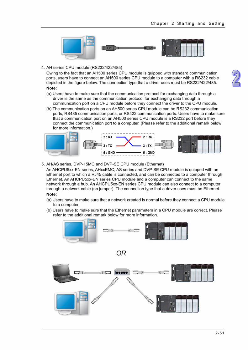
Chapter 2 Star t ing and Sett ing
2-51
4. AH series CPU module (RS232/422/485)
Owing to the fact that an AH500 series CPU module is quipped with standard communication ports, users have to connect an AH500 series CPU module to a computer with a RS232 cable depicted in the figure below. The connection type that a driver uses must be RS232/422/485. Note: (a) Users have to make sure that the communication protocol for exchanging data through a
driver is the same as the communication protocol for exchanging data through a communication port on a CPU module before they connect the driver to the CPU module.
(b) The communication ports on an AH500 series CPU module can be RS232 communication ports, RS485 communication ports, or RS422 communication ports. Users have to make sure that a communication port on an AH500 series CPU module is a RS232 port before they connect the communication port to a computer. (Please refer to the additional remark below for more information.)
5. AH/AS series, DVP-15MC and DVP-SE CPU module (Ethernet)
An AHCPU5xx-EN series, AHxxEMC, AS series and DVP-SE CPU module is quipped with an Ethernet port to which a RJ45 cable is connected, and can be connected to a computer through Ethernet. An AHCPU5xx-EN series CPU module and a computer can connect to the same network through a hub. An AHCPU5xx-EN series CPU module can also connect to a computer through a network cable (no jumper). The connection type that a driver uses must be Ethernet. Note: (a) Users have to make sure that a network created is normal before they connect a CPU module
to a computer. (b) Users have to make sure that the Ethernet parameters in a CPU module are correct. Please
refer to the additional remark below for more information.

ISPSoft User Manual
2-52
Additional remark AH series CPU modules may be equipped with USB ports, serial ports, and Ethernet ports. The serial ports and the Ethernet ports can be set by HWCONIFG in ISPSoft. Please refer to chapter 3 for more information. Compared with the serial port and the Ethernet port connections, it is more convenient to connect the USB port and AH series CPU module to a computer. If users want to connect a new CPU module to a computer, they can connect the CPU module to the computer with a USB cable, set the serial port and the Ethernet port on the CPU module through HWCONFIG in ISPSoft, and then download the communication parameters for the serial port and the Ethernet port.
2.4.8 Practical Connection Test
After users complete the steps above, they can check whether a computer communicates with a PLC normally by means of a simple test.
Users have to make sure of the items below before a PLC communicates with a computer. (a) The users have to make sure that COMMGR has been started normally, and the status of a
driver which will be specified is START. (b) The users have to make sure that the driver which will be specified is set correctly. If the
connection type that the driver uses is RS232, the users have to make sure that the communication protocol for exchanging data through the driver is the same as the communication protocol for exchanging data through a communication port on the PLC.
(c) The users have to make sure that a communication port used, e.g. a network interface card in the computer, a hub, or a serial port, is in a normal state.
(d) The users have to make sure that the driver, the station address, and the IP address which are specified in the Communication Setting window are correct. If an IP address is specified, the users have to check whether the IP address of the PLC is the same as the IP address specified.
(e) The users have to make sure that the PLC is correctly connected to the computer through a communication cable, power is supplied to the PLC, and the PLC operates normally.
After the users make sure of the items above, they can click System Information on the PLC menu in ISPSoft. ISPSoft will retrieve related information from the PLC. If the computer communicates with the PLC normally, the System Information window will appear, and the related information retrieved from the PLC will be displayed in the window.

3-1
Chapter 3 Configuring and Setting a PLC System
Table of Contents
3.1 Setting Parameters for a DVP Series PLC ............................................ 3-3 3.1.1 System Management Tools for a DVP Series PLC ........................ 3-3 3.1.2 Retentive Range ............................................................................ 3-3 3.1.3 Connected Information .................................................................. 3-7
3.2 Hardware Configuration Tool for AH and AS Series Modules ─ HWCONFIG…………………………………………………………………..3-7
3.2.1 Introduction of the Environment of HWCONFIG ............................ 3-8 3.2.2 Configuring a Module .................................................................... 3-11
3.2.2.1 Adding a Module .................................................................... 3-11 3.2.2.2 Assigning Devices to a Module ..............................................3-16 3.2.2.3 Editing a Comment ................................................................3-20 3.2.2.4 Deleting a Module ..................................................................3-22 3.2.2.5 Replacing a Module ...............................................................3-23 3.2.2.6 Searching for/Replacing a Module .........................................3-24 3.2.2.7 Copying/Pasting a Module .....................................................3-27 3.2.2.8 Cutting/Pasting a Module.......................................................3-29 3.2.2.9 Dragging a Module ................................................................3-31 3.2.2.10 Adding an Extension Rack ....................................................3-31 3.2.2.11 Deleting a Rack ....................................................................3-33 3.2.2.12 Replacing a Rack .................................................................3-34 3.2.2.13 Cutting/Copying/Pasting an Extension Rack ........................3-35 3.2.2.14 Dragging an Extension Rack ................................................3-37 3.2.2.15 Rearranging the Input/Output Devices .................................3-37 3.2.2.16 Show/Hide Module Names ...................................................3-38
3.2.3 Managing the Version of a Module ...............................................3-38 3.3 Setting the Parameters in an AH500 Series CPU Module ...................3-40
3.3.1 Opening the PLC Parameter Setting Window ...............................3-40 3.3.2 Setting the Basic CPU Parameters ...............................................3-42
3.3.2.1 CPU: Name ...........................................................................3-42 3.3.2.2 CPU: System .........................................................................3-43 3.3.2.3 CPU: Latched Device Range .................................................3-46
3.3.3 COM Port ......................................................................................3-48 3.3.4 Ethernet – Basic Setups ...............................................................3-49 3.3.5 Ethernet - Advance .......................................................................3-50
3.3.5.1 Ethernet - Advance: Filter ......................................................3-50 3.3.5.2 Ethernet─Advance: NTP .......................................................3-51 3.3.5.3 Ethernet - Advance: Email .....................................................3-52 3.3.5.4 Ethernet - Advance: Email Trigger .........................................3-53 3.3.5.5 Ethernet - Advance: Email and Trigger Configuration ............3-57 3.3.5.6 Ethernet - Advance: Socket ...................................................3-58 3.3.5.7 Ethernet - Advance: Web .......................................................3-60 3.3.5.8 Ethernet - Advance: Data Exchange ......................................3-60
3.3.6 Data Exchange Setup - COM .......................................................3-63

3-2
3.3.6.1 Data Exchange Setup - COM ................................................ 3-65 3.3.6.2 Data Exchange Setup - Ethernet ........................................... 3-66
3.4 Setting the Parameters in an AHxxEMC Series CPU Module ............. 3-67 3.4.1 Opening the PLC Parameter Setting Window .............................. 3-67 3.4.2 Options ......................................................................................... 3-68
3.4.2.1 Options - ID Info + System .................................................... 3-68 3.4.2.2 Option: COM Port Setting ...................................................... 3-70 3.4.2.3 Option- Ethernet Setting ........................................................ 3-71
3.4.3 Data Exchange - COM1, Data Exchange - COM2 and Data Exchange - Ethernet ...................................................................................... 3-71
3.4.3.1 Data Exchange - COM1 and Data Exchange – COM2 .......... 3-72 3.4.3.2 Data Exchange - Ethernet ..................................................... 3-74
3.5 Setting the Parameters in an AS Series CPU Module ......................... 3-74 3.5.1 Opening the PLC Parameter Setting Window .............................. 3-74 3.5.2 Options ......................................................................................... 3-75
3.5.2.1 Options - System Information ................................................ 3-75 3.5.2.2 Options-COM1 Port Setting & COM2 Port Setting ................ 3-81 3.5.2.3 Options - Ethernet Port Basic Setting .................................... 3-82 3.5.2.4 Ethernet Port Advance Setting .............................................. 3-82 3.5.2.5 Options - Function Card 1 Setting ......................................... 3-89 3.5.2.6 Options - Function Card 2 Setting ......................................... 3-90
3.5.3 Configuring AS-Series Remote Modules ...................................... 3-91 3.5.4 Data Exchange - COM1, Data Exchange - COM2 and Data Exchange
- Ethernet ...................................................................................... 3-93 3.5.4.1 Data Exchange - COM1 and Data Exchange - COM2 .......... 3-94 3.5.4.2 Data Exchange - Ethernet ..................................................... 3-96
3.6 Setting the Parameters in a Module .................................................... 3-96 3.6.1 Setting the Parameters in AH5x0 and AH5x1 Modules ................ 3-96 3.6.2 Setting the Parameters in AHxxEMC and AS Series Modules ... 3-100 3.6.3 Exporting and Importing the Parameters in a Module ................ 3-103 3.6.4 Setting the Parameters in an Intelligent Module ......................... 3-104
3.7 Management of the Parameters in AH and AS Series Hardware and Online Diagnosis ............................................................................... 3-105
3.7.1 Saving and Printing a Hardware Configuration ........................... 3-105 3.7.2 Purchase Order .......................................................................... 3-106 3.7.3 Rack Information List for AH Series ............................................ 3-107 3.7.4 Downloading/Uploading the System Parameters ....................... 3-108 3.7.5 I/O Scan ..................................................................................... 3-109 3.7.6 Online Diagnosis of AH Series ................................................... 3-111
3.7.6.1 Online Mode ........................................................................ 3-112 3.7.6.2 Module Information and Diagnosis ...................................... 3-113 3.7.6.3 Changing the Status of a Module Online ............................. 3-114 3.7.6.4 Monitoring Table .................................................................. 3-116
3.7.7 Online Diagnosis of AS Series ................................................... 3-116 Online Mode .......................................................................................... 3-117 Module Information and Diagnosis ........................................................ 3-117 Changing the Status of a Module Online ............................................... 3-118
3.8 Setting a RTC .................................................................................... 3-120 3.9 Setting the Memory in a PLC ............................................................. 3-121

Chapter 3 Conf igur ing and Sett ing a PLC System
3-3
By means of the built-in tools or functions in ISPSoft, users can configure a PLC or a whole system, and set parameters. In this chapter, the configuring of a system and the setting of parameters are introduced.
3.1 Setting Parameters for a DVP Series PLC
3.1.1 System Management Tools for a DVP Series PLC After users unfold the PLC section in the project management area in a project for a DVP series PLC, they will find the system management tools related to the PLC. Only after the PLC is connected to ISPSoft can some functions be enabled. The functions of the items are described below. Retentive Range: Users can set a range of latched devices in the PLC. Device Resource Allocation: Users can set a range of devices which will be automatically
assigned to symbols. Connected Information: Users can view the present system setting and parameters in the PLC.
The Device Resource Allocation function will be introduced in section 6.2.11. The Retentive Range function and the Connected Information function will be described in section 3.1.2 and section 3.1.3.
3.1.2 Retentive Range (1) After users double-click Retentive Range, the Retentive Range window will appear.

ISPSoft User Manual
3-4
(2) Click a device type.
(3) Since the latched devices in a PLC may not be consecutive devices, the users have to select a
block before they set a range of latched device.
(4) There is a rectangular bar in the setting area. The values at the two ends of the bar represent a
maximal value and a minimal value. The orange part represents a range of latched devices. If the setting area is gray, users can not set a range of latched devices in the block for the model selected. Please select values in the boxes. The value in the left box is a start address, and the value in the right box is an end address. The value in the left box must be less than the value in the right box. Besides, the value in the left box can not be less than the minimal value at the left end of the rectangular bar, and the value in the right box can not be larger than the maximal value at the right end of the rectangular bar.

Chapter 3 Conf igur ing and Sett ing a PLC System
3-5
(5) If all the devices in the block are not latched devices, the users can click Clear. After the users click Clear, the range of latched devices will be -1~-1.
(6) If the users want to restore the setting to the default values, they can click Default. After the
users click Default, the setting will be restored to the default values.
(7) If ISPSoft is connected to the PLC normally, users can click Read from PLC to read the setting
from the PLC.

ISPSoft User Manual
3-6
(8) After the setting is complete, the users can click Set in PLC to write the setting into the PLC if ISPSoft is connected to the PLC normally. The Retentive Range window will be closed automatically, and all the setting values will be memorized. When the ISPSoft project is saved, the setting values are also saved.
(9) If the users do not want to write the setting into the PLC for the time being, they can click OK to
apply all the setting. When the ISPSoft project is saved, the setting values are also saved.
(10) In addition to writing the setting into the PLC by clicking Set in PLC in the Retentive Range
window, the users can write the setting into the PLC when the program in the project is downloaded. After the users click Download PLC on the toolbar, they can select the Retentive Range checkbox in the Transfer Setup window, and click OK to download the setting to the PLC. Please refer to section 16.1.2 for more information.

Chapter 3 Conf igur ing and Sett ing a PLC System
3-7
3.1.3 Connected Information
If ISPSoft is connected to the PLC normally, the system will automatically retrieve the system parameters from the PLC after users double-click Connected Information in the project management area. The system parameters retrieved will be organized in a hierarchical structure under Connected Information. Users can view the information here, but they can not carry out any setting.
3.2 Hardware Configuration Tool for AH and AS Series Modules ─HWCONFIG
HWCONFIG is a built-in hardware configuration tool in ISPSoft. Users can configure racks, set CPU parameters, set module parameters, download/upload parameters, detect a hardware configuration online, and make a diagnosis through HWCONFIG. Currently the models supporting HWCONFIG include AH and AS series modules. This section will introduce common functions for all modules first and some special modules and specific functions.

ISPSoft User Manual
3-8
All parameters set in HWCONFIG must be downloaded to the CPU module so that they can take effect. (Please refer to section 3.7.4 for more information.) 3.2.1 Introduction of the Environment of HWCONFIG
After users double-click HWCONFIG in the project management area, the HWCONFIG window will appear.
Product list: Hardware available is listed in the catalogue.
System configuration area: It is the main working area. Users can configure and set a whole system in this area.
Information list: The information about the present system configuration is listed in the list. The present system configuration is displayed in the system configuration area. For AH-series modules, the number at the left side of a rack is a rack number and the number on a slot is a slot number. Users can select a module by clicking the module.
If users want to select a rack, they can move a mouse cursor to the extension port on the rack, and click the extension port.

Chapter 3 Conf igur ing and Sett ing a PLC System
3-9
When a rack is selected, the information about the present configuration for the rack is listed in the information list. If a module is selected, the information about the module on the list will be selected. If the information about a module is selected, the module in the system configuration area will be selected. Besides, if the configuration in the system configuration area is modified, the information on the information list will be updated.
The CPU modules of AS series can be extended by inserting extension modules in their right side and no rack is needed. Besides, they are equipped with the function card slot. In the system configuration area, the configuration of modules can be made as well. The extension card must be configured in the PLC Parameter Setting window. For the setting of the function card, refer to section 3.5. The data in the system configuration area and information list will be updated consistently as that for other series of modules.
All hardware available is listed in the product list. After a section is unfolded, all devices belongs to the section are listed under the section. If users click a device, the specifications for the device will be under the product list.
For some CPU modules, Delta Electronics provides specific configuration tools. Users could open these tools to make advanced configuration and parameter settings for modules, such as Ethernet/IP or EtherCAT network planning.
Function Card
Extension Modules

ISPSoft User Manual
3-10
In order to set the advanced parameters of CPU modules, first right-click a CPU icon on the system configuration area and then click Communication Software on the context menu and select the configuration tool. If the configurations and parameter settings in the HWCONFIG have not been saved yet, the system will require to save the settings before opening any corresponding software . After the software is opened, users could not do any editing in HWCONFIG before the tool software exclusive to intelligent modules is shut down. Some configuration tools need to be installed additionally. If the configuration software has not installed yet, a reminder message will show up asking users to installed.
Please refer to operation manuals of all software and modules for detailed operation after opening software.

Chapter 3 Conf igur ing and Sett ing a PLC System
3-11
3.2.2 Configuring a Module
3.2.2.1 Adding a Module
Method 1 Among AH series modules on the product list, users select one and then drag it to a vacant slot.
*. If users want to drag a module on the product list to the system configuration area, the module can only be put
on a vacant slot. If the module is dragged to an occupied slot, the system will prohibit this operation. AS series modules are designed without any rack equipped. The extension module can only be installed to the installation location, the right side of the module. And another installation place will appear to the right side of the installed module after the extension module is installed. Users could add the next extension modules in the same way one by one. The left side of the AS series module is used for adding the power module and only one power module can be installed.

ISPSoft User Manual
3-12
Method 2
(1) There are 4 ways to open the Module Select window for installing an AS series module. 1. Double-click a vacant slot 2. Right-click a vacant slot and then select ADD 3. Click an installation place 4. Right-click an installation place and then select Open
AH series
AS series
Extension Modules
Power Module

Chapter 3 Conf igur ing and Sett ing a PLC System
3-13
If the users click a module in the Module Selection window, the specifications for the module will appear in the Specification box. After the users double-click a module in the Module Selection window, the module will be added.
Method 3
(1) After users click a blank on the information list, the Module Selection window will appear. The users can also double-click a blank on the information list, and click Add on the context menu to open the Module Selection window.
AS series
AH series

ISPSoft User Manual
3-14
(2) If the users click a module in the Module Selection window, the specifications for the module
will appear in the Specification box. After the users double-click a module in the Module Selection window, the module will be added.
AH series

Chapter 3 Conf igur ing and Sett ing a PLC System
3-15
No matter which method is used to add a module, the configuration in the system configuration area and the information on the information list will be updated after a module is added.
AS series

ISPSoft User Manual
3-16
3.2.2.2 Assigning Devices to a Module
The data in AH series modules needs to be updated constantly. For example, analog signals received by an analog input module are updated constantly, and converted to data which can be processed by a CPU module. As a result, the system automatically assigns devices to a module so that the data in the module can be stored. The devices assigned to a module are displayed in the Input Device Range cell and the Output Device Range cell on the information list. Please refer to the following example. AS series CPU module groups do not support manual assignment of devices but automatic assignment of fixed devices according to the installment place of a module. However, for RTU remote module groups, only the start device address of the first SCM module can be set and subsequent modules are configured in order. For configuration of AS-series remote modules, refer to section 3.5.3.

Chapter 3 Conf igur ing and Sett ing a PLC System
3-17
AH16AM10N-5A (slot 0) AH16AM10N-5A is a digital input module which has 16 inputs. The system assigns X0.0~X0.15 to AH16AM10N-5A so that data received by AH16AM10N-5A can be stored.
AH16AN01T-5A (slot 1) AH16AN01T-5A is a digital output module which has 16 outputs. The system assigns Y0.0~Y0.15 to AH16AN01T-5A so that data sent by AH16AM10N-5A can be stored.
AH04AD-5A (slot 2) AH04AD-5A is an analog input module which has four channels. The system assigns D0~D7 to AH04AD-5A. After analog signals received by AH04AD-5A are converted into digital data, the digital data will be stored in D0~D7.
AH16AP11T-5A (slot 3) AH16AP11T-5A is a digital input/output module which has 8 inputs and 8 outputs. The system assign X1.0~X1.15 to AH16AP11T-5A so that data received by AH16AP11T-5A can be stored. (X1.0~X1.7 are actually used.) The system also assigns Y1.0~Y1.15 to AH16AP11T-5A so that data sent by AH16AP11T-5A can be stored. (Y1.0~Y1.7 are actually used.)
AH20MC-5A (slot 4) AH20MC-5A is a motion control module. Owing to the fact that the data in AH20MC-5A does not need to be updated constantly, the system does not assign any device to AH20MC-5A.
If users want to know functions to which devices assigned correspond, they can double-click the module or the information about the module on the information list to open the Parameter Setting window.
*. To avoid the cells which can be edited, if users want to double-click the information about a module on the
information list, they can double-click Slot No. cell, the Label cell, or the Description cell. After users click the Normal Exchange Area tab in the Parameter Setting window, they can see functions to which devices correspond.

ISPSoft User Manual
3-18
The system automatically assigns devices to a module so that the data in the module which needs to be updated constantly can be stored. The parameters in a module do not need to be updated constantly. Users assign data registers to a module so that the parameters in the module can be stored. When the system operates, the data registers in a CPU module are synchronized to the parameters in the module. As a result, the users can access the module through the data registers. Accessing a module through the data registers is more efficient than accessing the module through the instruction FROM/TO. As the example below shows, D3000 corresponds to the parameter CH0 Average Time in the Parameter Setting window for AH04AD-5A. After the parameters in HWCONFIG are downloaded to the CPU module, users can change the value of the parameter CH0 Average Time by changing the value in D3000 in the CPU module. Besides, if users write a value which is not allowed by a parameter into a data register during the operation of the system, the system will restore the value in the data register and the value of the parameter to the original values.
*. Please refer to section 3.6 for more information about the setting of parameters in a module. Please refer to
programming manuals for more information about the instruction FROM/TO. The Input/Output Device Range column on the information list can be defined not only by the system, but also by users. Users can click a cell on the information list, and then click , or type a

Chapter 3 Conf igur ing and Sett ing a PLC System
3-19
start address directly. After the Manual Assignment window appears, the users can type a start address, and click OK.
Devices that users assign to a module so that the data in the module can be stored can not overlap data registers that the users assign to a module so that the parameters in the module can be stored. If a device address typed conflicts with another device address, the system will modify the device address which is typed, and provide a device address which can be used. For example, if users want to assign D3000 which has been assigned to a module to another module, the system will provide a device address which can be used.
After the input/output device addresses assigned to a module are changed, the input/output device addresses assigned to a module added will follow the new input/output device addresses assigned to the preceding module, and the input/output device addresses which have been assigned will be skipped. Even if the new input/output device addresses assigned to the preceding module are not the largest addresses, the input/output device addresses assigned to the module added will follow the new input/output devices addresses. Please refer to the following example. The input device addresses assigned to AH04AD-5A installed in slot 2 is changed to D50~D57.

ISPSoft User Manual
3-20
The input device addresses assigned to a module added follow D50~D57 rather than D100~D107. As a result, D58~D65 are assigned to AH04AD-5A which is installed in slot 3.
AS series modules do not support manual assignment of device addresses of modules. For assignment of start device addresses of remote modules, refer to section 3.5.3.
3.2.2.3 Editing a Comment
After users click the gray area at the top of the system configuration area, they can type a comment about the hardware configuration in the drop-down box that appears. If users want to start a new line of text at a specific point, they can press Shift+Enter on the keyboard. After the comment is typed, users can press Enter on the keyboard.

Chapter 3 Conf igur ing and Sett ing a PLC System
3-21
After users click the Comment cell for a module among AH5x0 and AH5x1 series modules on the information list, they can press a key on the keyboard, or click to open the Comment window. The users can type a comment about the module in the Comment window.
After users double-click the Comment cell for a module among AHxxEMC and AS series modules on the information list, they can press a key on the keyboard, or click to open the Comment window. The users can type a comment about the module in the Comment window.

ISPSoft User Manual
3-22
3.2.2.4 Deleting a Module
There are two ways to delete a module which has been configured. (The CPU module and AH-series power supply module cannot be deleted.) Method 1
(1) Select a module which will be deleted from the system configuration area or information list.
(2) Click Delete on the Edit menu, click on the toolbar, or press Delete on the keyboard.
Method 2
(1) Right-click a module which will be deleted from the system configuration area or information list.
AH series
AH series
AS series
AS series
AH series

Chapter 3 Conf igur ing and Sett ing a PLC System
3-23
(2) Click Delete on the context menu.
3.2.2.5 Replacing a Module
(1) Right-click one of AH series modules which will be replaced in the system configuration area or on the information list. (The CPU module and the power supply module cannot be replaced.)
(2) Point to Replace on the context menu, and then click Sam Type or All.
Same Type
A module selected is replaced by a same type of module. After the module is replaced, the input/output devices assigned to the new module are the same as the input/output devices assigned to the module replaced. Besides, if the parameters in the new module are not the same as the parameters in the module replaced, the setting of the parameters in the new module will be restored to the default values.
All A module selected can be replaced by any type of module. After the module is replaced, the different input/output devices will be assigned to the new module, and the setting of the parameters in the new module will be restored to the default values.
(3) After users click Same Type or All, the Module Selection window will appear. Items which can be selected will be displayed in the window. After the users decide on a module, they can double-click the module in the window.
AH series
AS series
AS series

ISPSoft User Manual
3-24
3.2.2.6 Searching for/Replacing a Module
(1) After users click Search on the Option menu, the Find and Replace window will appear.
(2) Click in the Find what box, select a module in the Module Selection window, and
double-click the module. The users can also type part of a module model in the Find what box. Finally, click Find.
(3) After the search is complete, modules meet the search condition will be listed in the list. After
the users double-click an item on the list, the module corresponding to the item in the system

Chapter 3 Conf igur ing and Sett ing a PLC System
3-25
configuration area will be selected.
(4) If the users want to replace a module, they can click a module which will be replaced on the
search list. If the users want to replace the module with a same type of module, they can select the Same Type checkbox.
The Same Type checkbox is selected. A module selected is replaced by a same type of module. After the module is replaced, the input/output devices assigned to the new module are the same as the input/output devices assigned to the module replaced. Besides, if the parameters in the new module are not the same as the parameters in the module replaced, the setting of the parameters in the new module will be restored to the default values.
The Same Type checkbox is not selected. A module selected can be replaced by any type of module. After the module is replaced, the different input/output devices will be assigned to the new module, and the setting of the parameters in the new module will be restored to the default values.
(5) Click in the Replace with box, select a module in the Module Selection window, and double-click the module. Owning to the fact that a module must be replaced by a specific module, typing a module model or part of a module model in the Replace with box is not allowed.

ISPSoft User Manual
3-26
*. If the Replace with box is blank, a module selected will be deleted after Replace is clicked.
(6) After the setting of the replacement condition is complete, the users can click Replace to replace the module selected with the new module. After the replacement is complete, the search list will be updated, and the next module will be selected automatically.
(7) If the users want to replace all the modules on the list, they can click Replace All after the
setting of the replacement condition is complete. All the modules on the list will be replaced by the new module.

Chapter 3 Conf igur ing and Sett ing a PLC System
3-27
3.2.2.7 Copying/Pasting a Module
There are two ways to copy a module. (The CPU module and the power supply module can not be copied/pasted.) Method 1
Right-click a module which will be copied in the system configuration area or on the information list, and then click Copy on the context menu.
Method 2
(1) Click a module which will be copied in the system configuration area or on the information list.
(2) Click Copy on the Edit menu, or on the toolbar.
There are two ways to paste a module. Method 1
Right-click a slot on which a module will be pasted in the system configuration area or on the information list, and then click Paste on the context menu.
Method 2
(1) Click a slot on which a module will be pasted in the system configuration area or on the information list.

ISPSoft User Manual
3-28
(2) Click Paste on the Edit menu, or on the toolbar.
The two methods above can be applied to AS series modules as well. However, AS series modules are designed without any rack equipped and thus they can only be pasted to the right-side installation place or the blank row at the bottom side.
The copied module will be pasted to the left of the existing module by clicking Paste on the existing module. For example, Click Paste on the context menu on 04AD module and as a result, 06XA module is pasted to the left of 04AD module as shown in the following figure.
Additional remark When a module is copied/pasted, the parameters in the module are processed as follows. Input/Output device range: The input/output devices assigned to the module cut are
automatically assigned to the module pasted. Comment about the module: The comment about the module copied is copied into the module
pasted. Parameters in the module: The parameters in the module cut are copied into the module pasted. Data registers: The data registers assigned to the module copied are automatically assigned to
the module pasted. Parameters in the intelligent module: The setting of the parameters in the intelligent module is
not copied, and is restored to the default values. The users have to set the parameters again.
As the example below illustrates, the module on slot 0 is the module which is copied, and the module on slot 1 is the module which is pasted.

Chapter 3 Conf igur ing and Sett ing a PLC System
3-29
*. Some intelligent modules can be set by means of exclusive configuration tools. Please refer to section 3.6.4 for
more information. *. The data register function is not supported by AHxxEMC and AS300 series.
3.2.2.8 Cutting/Pasting a Module
There are two ways to cut a module. (The CPU module and the power supply module can not be cut/pasted.) Method 1
Right-click a module which will be cut in the system configuration area or on the information list, and then click Cut on the context menu.
Method 2
(1) Click a module which will be cut in the system configuration area or on the information list.
(2) Click Cut on the Edit menu, or on the toolbar.
There are two ways to paste a module. Method 1
Right-click a slot on which a module will be pasted in the system configuration area or on the information list, and then click Paste on the context menu.
Method 2
(1) Click a slot on which a module will be pasted in the system configuration area or on the information list.

ISPSoft User Manual
3-30
(2) Click Paste on the Edit menu, or on the toolbar.
The two methods mentioned above to cut a module can be applied to AS series modules as well. AS series modules are designed without any rack equipped and thus, it means that the cut module is moved to the end place through being pasted to the installation place. For example, 04AD is pasted to the installation place after being cut and as a result, 04AD is moved to the right side of 06XA.
If one module which has been cut is pasted to the place of another module, the cut module will be inserted to the left side of the module. For example, 04AD is pasted to the place of 06XA after being cut and as a result, 04AD is moved to the left side of 06XA as below.
Additional remark A module which is cut can only be pasted once. When a module is cut/pasted, the parameters in the module are processed as follows. Input/Output device range: The input/output devices assigned to the module cut are
automatically assigned to the module pasted. Comment about the module: The comment about the module cut is copied into the module
pasted. Parameters in the module: The parameters in the module cut are copied into the module pasted. Data registers: The data registers assigned to the module cut are automatically assigned to the
module pasted. Parameters in the intelligent module: The setting of the parameters in the intelligent module is
copied. For AS series modules, the input/output device range will be rearranged automatically according
to the installation place of a module. *. Some intelligent modules can be set by means of exclusive configuration tools. Please refer to section 3.6.4 for
more information.

Chapter 3 Conf igur ing and Sett ing a PLC System
3-31
3.2.2.9 Dragging a Module
All modules in the system configuration area can be dragged by the mouse except the CPU module and the power supply module. There will be two conditions when dragging an AH series module. Condition 1
Drag a module to a vacant slot when the left mouse button is held. The module will be moved to a new position.
Condition 2
Drag a module to an occupied slot when the left mouse button is held. The two modules will be interchanged.
Owing to the fact that the AS series is not a rack equipped, the module which is dragged to other module place is actually inserted to the left side of the target module and a red arrow appears on the inserted place.
* When a module is dragged, the input/output devices assigned to the module, the comment about the module, the parameters in the module, the data registers assigned to the module, and the parameters in the intelligent module are also dragged. But, for AS series modules the input/output device range will be rearranged automatically according to the installation place of a module.
3.2.2.10 Adding an Extension Rack
There are two ways to add an extension rack for AH series modules. Method 1
Drag an extension rack which will be added to the product list to the system configuration area. After the extension rack is dragged to the blank in the system configuration area, it will be under the present rack.

ISPSoft User Manual
3-32
If an extension rack is dragged to a present rack, it will be put above the present rack.
*. An extension rack can not be put above the main rack.
Method 2 Right-click the blank in the system configuration area, click Add on the context menu, and double-click an extension rack which will be added in the Rack Selection window. The extension rack will be under the present rack.

Chapter 3 Conf igur ing and Sett ing a PLC System
3-33
Right-click the left side of a rack, click Add on the context menu, and double-click an extension rack which will be added in the Rack Selection window. The extension rack will be under the rack.
3.2.2.11 Deleting a Rack
There are two ways to delete a rack. (The main extension rack can not be deleted.) Method 1
(1) Click the left side of a rack which will be deleted.
(2) Click Delete on the Edit menu, click on the toolbar, or press Delete on the keyboard.

ISPSoft User Manual
3-34
Method 2 Right-click the left side of a rack which will be deleted, and then click Delete on the context menu.
The extension rack function is not supported by AHxxEMC and AS series.
3.2.2.12 Replacing a Rack
(1) Right-click the left side of a rack which will be replaced, and then click Replace on the context menu.
(2) Double-click a rack in the Rack Selection window.

Chapter 3 Conf igur ing and Sett ing a PLC System
3-35
Additional remark If the number of slots on the new rack is less than the number of slots on the original rack, the modules on the original rack which can not be installed on the new rack will be deleted automatically. As a result, users have to make sure of the number of slots on the new rack before they replace a rack.
3.2.2.13 Cutting/Copying/Pasting an Extension Rack
There are two ways to copy or cut an extension rack. (The main rack can not be copied/cut/pasted.) Method 1
Right-click the left side of a rack which will be copied or cut, and then click Copy or Cut on the context menu.
Method 2
Click the left side of a rack which will be copied or cut.
If users want to copy the rack, they can click Copy on the Edit menu, or click on the toolbar.

ISPSoft User Manual
3-36
If users want to cut the rack, they can click Cut on the Edit menu, or click on the toolbar.
There are two ways to paste an extension rack. If an extension rack is pasted on the blank in the system configuration area, it will be under the present racks. If an extension rack is pasted on a present extension rack, it will be put above the present extension rack.
Method 1 Right-click the blank or a present rack in the system configuration area, and then click Paste on the context menu.
Method 2
Click the blank or a present rack in the system configuration area, and then click Paste on the Edit menu, or on the toolbar.
The extension rack function is not supported by AHxxEMC and AS series. Additional remark When an extension rack is cut/pasted, the parameters in the modules on the extension rack are processed as follows. Input/Output device range: The input/output devices assigned to the modules on the extension
rack cut are automatically assigned to the modules on the extension rack pasted.
Comments about the modules: The comments about the modules on the extension rack cut are

Chapter 3 Conf igur ing and Sett ing a PLC System
3-37
copied into the modules on the extension rack pasted. Parameters in the modules: The parameters in the modules on the extension rack cut are
copied into the modules on the extension rack pasted. Data registers: The data registers assigned to the modules on the extension rack cut are
automatically assigned to the modules on the extension rack pasted. Parameters in the intelligent modules: The setting of the parameters in the intelligent modules
is copied. When an extension rack is copied/pasted, the parameters in the modules on the extension rack are processed as follows. Input/Output device range: The input/output device addresses assigned to the modules on the
extension rack pasted follow the input/output device addresses assigned to the modules on the extension rack copied.
Comments about the modules: The comments about the modules on the extension rack copied are copied into the modules on the extension rack pasted.
Parameters in the modules: The parameters in the modules on the extension rack cut are copied into the modules on the extension rack pasted.
Data registers: The data register addresses assigned to the modules on the extension rack pasted follows the data registers addresses assigned to the modules on the extension rack copied.
Parameters in the intelligent modules: The setting of the parameters in the intelligent modules is not copied, and is restored to the default values.
*. Some intelligent modules can be set by means of exclusive configuration tools. Please refer to section 3.6.4 for more information.
3.2.2.14 Dragging an Extension Rack
Drag an extension rack to another extension rack when the left mouse button is held. The two extension racks will be interchanged. When the extension rack is dragged, the input/output devices assigned to the modules on the extension rack, the comments about the modules on the extension rack, the parameters in the modules on the extension rack, the data registers assigned to the modules on the extension rack, and the parameters in the intelligent modules are also dragged. However, the main rack is always at the top of the system configuration area.
The extension rack function is not supported by AHxxEMC and AS series.
3.2.2.15 Rearranging the Input/Output Devices
During the configuration of an AH series module, modules may be dragged or copied/cut/pasted several times. The input/output devices may be automatically assigned to the modules by the system, and may not be arranged in order. After users click Input/Output Device Rearrange on the File menu, the input/output devices assigned to all modules will be rearranged according to the slot numbers and the rack numbers. The rearrangement of the input/output devices does not change the data registers assigned to the modules. During the rearrangement, if the input/output devices assigned to the modules conflicts with the data registers assigned to the modules, the system will skip the data registers assigned to the module, and provide the devices which can be used.

ISPSoft User Manual
3-38
For AS series, the button on the tool bar can be used to rearrange the input/output devices.
3.2.2.16 Show/Hide Module Names
For AS series, users could select to show or hide module names in the system configuration area by clicking on the tool bar.
3.2.3 Managing the Version of a Module
The functions of a module or the parameters in the module vary with the versions of the module. In HWCONFIG, the functions of the modules and the parameters in the modules are defined in a document called MDS. When ISPSOft is installed, the latest MDS document will be also installed. An MDS document provides the information about the firmware versions of the modules. If users want to configure modules in HWCONFIG, they can select a suitable configuration according to the firmware versions of the actual modules. Besides, the parameters which can be set in the modules vary with the firmware versions of the modules which are set. If the firmware version of a module set in HWCONFIG is older than the firmware version of the actual module, the module will operate normally after the parameters are downloaded. If the firmware version of a module set in HWCONFIG is newer than the firmware version of the actual module, the module will not operate normally after the parameters are downloaded. Please refer to the descriptions in the table below for more information.

Chapter 3 Conf igur ing and Sett ing a PLC System
3-39
Difference Compatibility The firmware version set is older than the actual firmware version.
The module operates normally. Functions or parameters not defined in HWCONFIG are assigned with the default values.
The firmware version set is newer than the actual firmware version.
The module cannot operate, and is in an erroneous condition. Users have to select a firmware version which is the same as the firmware version of the actual module in HWCONFIG, check the parameters, and download the parameters again.
*. The compatibility mechanism described above only applies to modules whose firmware version is 1.0 or above. A
firmware version below 1.0 is not compatible with firmware version 1.0 or above. *. The equipment description file can be in DDF or MDS format based on different models.
If users want to set the firmware version of a module, they can select a version number in the Firmware Version drop-down list cell on the information list. If the firmware version of a module is unknown, no version number will be displayed.
If users want to change the firmware versions of the modules of a certain model, they can click Alter Overall Firmware Version on the Option menu. The Alter Overall Firmware Version window will appear.
Click in the Module Name box, select a module model in the Module Selection window, and double-click the module model.

ISPSoft User Manual
3-40
Select a version number in the Firmware Version drop-down list cell. After the setting is complete, users can click OK to change the firmware versions of the modules specified.
The firmware version altering is not supported by AS series. Additional remark Users can know the firmware version of an actual module by clicking I/O Scan on the Option menu. If ISPSfot is connected to the CPU module, users can get the information about the firmware version of an actual module in the Module Information window. If users want to know the firmware version of an actual module by clicking I/O Scan on the Option menu, or viewing the information about the firmware version of an actual module in the Module Information window, ISPSoft must be connected to the CPU module normally, and the installation of modules must be completed. Please refer to section 3.7.5 and section 3.7.6 for more information.
3.3 Setting the Parameters in an AH500 Series CPU Module
3.3.1 Opening the PLC Parameter Setting Window
After users double-click the CPU module in the system configuration area, the PLC Parameter Setting window will appear. The parameters which can be set vary with the models of the CPU modules.
Before the parameters in a CPU module are set, users have to refer to the operation manual for the CPU module. To prevent damage to the system or staff, the users have to make sure of the effect that the parameters which are set have on the CPU module and the whole system.
*. The parameter settings are not effective until they are downloaded to the CPU module. Refer to section 3.7.4 for the download method.

Chapter 3 Conf igur ing and Sett ing a PLC System
3-41
The parameters are classified into several types. The users can click the primary tabs at the top of the window, and the secondary tables at the bottom of the window to set the parameters.

ISPSoft User Manual
3-42
3.3.2 Setting the Basic CPU Parameters
3.3.2.1 CPU: Name
After users click the CPU tab at the top of the window, and the Name tab at the bottom of the window, they can type 32 characters at most in the Name box, and 60 characters at most in the Comment box. There is no restriction on characters which can be typed in the boxes. Characters typed in the boxes can include special marks and spaces. However, the users have to note that a Chinese character occupies two characters.
After an ISPSoft project is created, the project name will be taken as the default name of the CPU module, and the default name of the CPU module will be attached to the model in the project management area. Users can change the default name of the CPU module in the Name box later.
Users can identify a device by means of the name of the device. When several devices are connected to one network, users can check whether a device connected to the computer is the device they expect by checking the device name. To prevent errors, if users want to download/upload the program, the system will remind the users to check the name of the CPU module and the name attached to the model in the project management area, when the name of the CPU module is different from the name attached to the model in the project management area.

Chapter 3 Conf igur ing and Sett ing a PLC System
3-43
3.3.2.2 CPU: System
After users click the CPU tab at the top of the window, and the System tab at the bottom of the window, they can set the parameters in the CPU module.
Clear Non-latched Device (STOPRUN)
If the Enable checkbox is selected, the states of the non-latched devices, and the values in the non-latched devices are cleared when the CPU module begins to run.
Y state (STOPRUN)
When the CPU module begins to run, the states of the Y devices are OFF, retained, or restored to the states before the CPU module’s stopping running. Clear: All Y devices are set to OFF. Retain Present State: The states of the Y devices are retained. Previous State before STOP: The states of the Y devices are restored to the states before the
CPU module’s stopping running.

ISPSoft User Manual
3-44
Reset Button & Clear Button Whether the RST button and CLR button on the CPU module is enabled or disabled depends on the setting of these parameters. Please refer to an operation manual for more information about the functions of the buttons.
Watchdog Timeout
Users can set a timeout during which the program is scanned. Generally speaking, the watchdog timeout is reset whenever the scan of the program is complete. If the scan procedure can not be completed within the time set for some reason, the watchdog timeout occurs, and the CPU module will be in an erroneous condition. Please refer to operation manuals for more information about troubleshooting.
Enable Constant Scan
Users can select the Enable Constant Scan checkbox, and set a scan time. If the actual scan time is less than setting value, the CPU module will not carry out the next scan until the setting value is reached. If the actual scan time is larger than the setting value, the CPU module will ignore the setting value, and operate according to the actual scan time. Besides, if the scan time set is larger than the watchdog timeout set, a watchdog timeout occurs when the CPU module operates.
Interval Interrupt Time
An AH500 series CPU module provides four interrupts. Users can set intervals of triggering the interrupts. In ISPSoft, a timed interrupt is created through a task and a POU. Please refer to chapter 5 for more information.

Chapter 3 Conf igur ing and Sett ing a PLC System
3-45
Enable Remote Run
If the Enable Remote Run checkbox is selected, users can specify an X device which controls the status of the CPU module. For example, the CPU module runs when the state of X0.0 is ON, and the CPU module stops running when X0.0 is OFF.
Constant Communication Response
If the Enable checkbox is not selected, commands received through the communication ports will not be processed until the scan cycle is complete. If the Enable checkbox is selected, commands received through the communication ports will be processed every specific period of time. However, the scan procedure is interrupted when the system processes commands received through the communication ports. As a result, the scan time will be prolonged if the Enable checkbox is not selected. Please make sure that the operation of the system is not affected when the function is used.
Error Log Location
If the PLC option button is selected, error logs will be stored in the special data registers in the CPU modules. If the PLC and PLC CARD option button is selected, error logs will be stored not only in the CPU module, but also in the memory card. Twenty error logs at most can be stored in an AH500 series CPU module. If there are more than twenty error logs, the oldest error log will be overwritten by the latest error log. However, if the PLC and PLC CARD option button is selected, and there are more than twenty error logs, the oldest error log will be backed up in the memory card before the oldest error log is overwritten.
CPU Operation at Program Error & CPU Operation at Bus Fault
If an error occurs, the status of the CPU may change. The status of the CPU depends on an error code generated. Users can define the status of the CPU module for some errors. They can select the Stop option button or the Continue option button in the CPU Operation at Program Error section, select the Stop option button or the Continue option button in the CPU Operation at Bus Fault section, and download the parameters to the CPU module. Please refer to operation

ISPSoft User Manual
3-46
manuals or related technical documents for more information.
Remote Reset
If the Enable checkbox is selected, the CPU module can be reset through a remote system. After users select the Enable checkbox, and download the parameter to the CPU module, they can click Format PLC Memory… on the PLC menu, and select the Reset PLC Memory (Factory Setting) option button in the Format PLC Memory window.
3.3.2.3 CPU: Latched Device Range
After users click the CPU tab at the top of the window, and the Latched Device Range tab at the bottom of the window, they can set a range of latched devices.
(1) After users click a device type, they can be set a range of latched devices. There is a
rectangular bar in the setting area. The values at the two ends of the bar represent a maximal value and a minimal value. The blue part represents a range of latched devices.
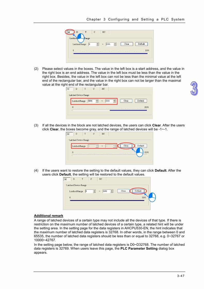
Chapter 3 Conf igur ing and Sett ing a PLC System
3-47
(2) Please select values in the boxes. The value in the left box is a start address, and the value in
the right box is an end address. The value in the left box must be less than the value in the right box. Besides, the value in the left box can not be less than the minimal value at the left end of the rectangular bar, and the value in the right box can not be larger than the maximal value at the right end of the rectangular bar.
(3) If all the devices in the block are not latched devices, the users can click Clear. After the users
click Clear, the boxes become gray, and the range of latched devices will be -1~-1.
(4) If the users want to restore the setting to the default values, they can click Default. After the
users click Default, the setting will be restored to the default values.
Additional remark A range of latched devices of a certain type may not include all the devices of that type. If there is restriction on the maximum number of latched devices of a certain type, a related hint will be under the setting area. In the setting page for the data registers in AHCPU530-EN, the hint indicates that the maximum number of latched data registers is 32768. In other words, in the range between 0 and 65535, the number of latched data registers should be less than or equal to 32768, e.g. 0~32767 or 10000~42767. In the setting page below, the range of latched data registers is D0~D32768. The number of latched data registers is 32769. When users leave this page, the PLC Parameter Setting dialog box appears.

ISPSoft User Manual
3-48
3.3.3 COM Port After users click the COM Port tab at the top of the window, they can set the communication ports in the CPU module. If the CPU module is equipped with two communication ports, there are two setting areas for the two communication ports, and the two communication ports are set individually. (AHCPU5xx-RS2 is equipped with two communication ports.) Please refer to section 2.4.7 for more information about connecting to a CPU module through a communication port.
Users can select RS232, RS485, or RS422 in the Communication Type drop-down list box.
Users can select a communication speed in the Baud Rate drop-down list box. If a RS-232 cable is used, the communication speed can be 9600 bps, 19200 bps, 38400 bps, 57600 bps, 115200 bps. If a RS-485 cable or a RS-422 cable is used, the communication speed can be 9600 bps, 19200 bps, 38400 bps, 57600 bps, 115200 bps, 230400 bps, 460800 bps, or 921600 bps.
Users can set the communication protocol parameters. If the RTU option button is selected in the Transfer Mode section, the 8 bit option button in the Data Length section is automatically selected.
Users can set a station address. A device on a network can be identified by means of the station address of the device. The station address of a device on a network can not be the same as the station address of another device on the same network. The station address of a device must be within the range between 0 and 247. If the communication port functions as a slave, and there are other slaves, the station address of the communication port can not be 0. Station address 0 has the meaning of broadcasting to all slaves in a communication protocol. If a master specifies in a data packet that data must be sent to station address 0, the data will be sent to all slaves. No matter what station address of these slaves are, these slaves will receive the data packet.
If the sending of a command fails, the CPU module will retry the sending of the command. Users can set the number of times the sending of a command is retired in this box. The number of
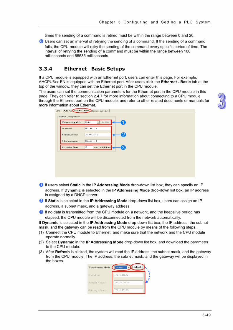
Chapter 3 Conf igur ing and Sett ing a PLC System
3-49
times the sending of a command is retired must be within the range between 0 and 20. Users can set an interval of retrying the sending of a command. If the sending of a command
fails, the CPU module will retry the sending of the command every specific period of time. The interval of retrying the sending of a command must be within the range between 100 milliseconds and 65535 milliseconds.
3.3.4 Ethernet – Basic Setups
If a CPU module is equipped with an Ethernet port, users can enter this page. For example, AHCPU5xx-EN is equipped with an Ethernet port. After users click the Ethernet - Basic tab at the top of the window, they can set the Ethernet port in the CPU module. The users can set the communication parameters for the Ethernet port in the CPU module in this page. They can refer to section 2.4.7 for more information about connecting to a CPU module through the Ethernet port on the CPU module, and refer to other related documents or manuals for more information about Ethernet.
If users select Static in the IP Addressing Mode drop-down list box, they can specify an IP
address. If Dynamic is selected in the IP Addressing Mode drop-down list box, an IP address is assigned by a DHCP server.
If Static is selected in the IP Addressing Mode drop-down list box, users can assign an IP address, a subnet mask, and a gateway address.
If no data is transmitted from the CPU module on a network, and the keepalive period has elapsed, the CPU module will be disconnected from the network automatically.
If Dynamic is selected in the IP Addressing Mode drop-down list box, the IP address, the subnet mask, and the gateway can be read from the CPU module by means of the following steps. (1) Connect the CPU module to Ethernet, and make sure that the network and the CPU module
operate normally. (2) Select Dynamic in the IP Addressing Mode drop-down list box, and download the parameter
to the CPU module. (3) After Refresh is clicked, the system will read the IP address, the subnet mask, and the gateway
from the CPU module. The IP address, the subnet mask, and the gateway will be displayed in the boxes.

ISPSoft User Manual
3-50
3.3.5 Ethernet - Advance
If a CPU module is equipped with an Ethernet port, users can enter this page. For example, AHCPU5xx-EN is equipped with an Ethernet port. After users click the Ethernet─Advance tab at the top of the window, they can set devices on a network.
3.3.5.1 Ethernet - Advance: Filter
After users click the Ethernet - Advance tab at the top of the window, and the Filter tab at the bottom of the window, they can set a filter. Devices on a network are filtered. The setting here ensures that objects communicating with the CPU module are devices which are allowed.
Enable IP Address Filter
If the Enable IP Address Filter checkbox is selected, devices whose IP addresses are listed in the table will be allowed to communicate with the CPU module, and the CPU module will discard data packets sent from devices whose IP addresses are not listed in the table. The steps of setting the function are as follows. Sixteen groups of IP address at most can be listed in the table. (1) Select the Enable IP Address Filter checkbox, and then double-click an item which will be
modified or added in the table.
(2) Type a start IP address and an end address in the IP address Filter window. The start IP
address must be less than the end IP address. Finally, click OK.
Enable Static ARP Table
Users can use this function to set MAC addresses and corresponding IP addresses. The MAC address of every device is unique. If the MAC address of device A is known, the MAC address can be bound to the IP address assigned to device A. The CPU module will regard the IP address as the exclusive address of device A. Even if device B is assigned the same IP address, the CPU module does not respond to device B. The steps of setting the function are as follows. Sixteen groups of addresses at most can be listed in the table.

Chapter 3 Conf igur ing and Sett ing a PLC System
3-51
(1) Select the Enable Static ARP Table checkbox, and then double-click an item which will be modified or added in the table.
(2) Type an IP address and a MAC address in the Static ARP Table window. Finally, click OK.
Take the tables below for example. After the setting in the tables is downloaded to the CPU module, devices whose IP addresses are within the range between 192.168.1.1 and 192.168.1.50, and devices whose IP addresses are within the range between 192.168.1.100 and 192.168.1.150 are allowed to communicate with the CPU module if the CPU module operates. Besides, if the CPU module communicates with a device whose IP address of 192.168.1.20, the MAC address of the device must be BA:99:BA:14:BA:51. Likewise, if the CPU module communicates with a device whose IP address is 192.168.1.21, the MAC address of the device must be 00:10:5A:81:CA:FD.
*1. If users want to know the MAC address of a CPU module, they can click Online Mode in HWCONFIG to view the
information about the CPU module (section 3.7.6), or click System Information in ISPSoft to get the information about the CPU module connected and the status of the CPU module (section 17.6.1).
3.3.5.2 Ethernet─Advance: NTP
After users click the Ethernet─Advance tab at the top of the window, and the NTP tab at the bottom of the window, they can enable the function of synchronizing the real-time clock in the CPU module to an NTP server, and carry out the related setting. NTP will not be introduced here. Please refer to related documents or manuals for more information about NTP.

ISPSoft User Manual
3-52
Select the Enable NTP Client Service checkbox, and then set the related parameters.
Users can set the IP address of an NTP server. The CPU module corrects the time inside itself
by connecting to the server periodically. Users can set an interval of correcting the time in the CPU module. If the interval is thirty minutes,
the CPU module will connect to the NTP server every thirty minutes. After users select the Daylight Saving checkbox, they can select a start date and an end data.
Users can select a time zone in the Time Zone drop-down list box.
3.3.5.3 Ethernet - Advance: Email
After users click the Ethernet - Advance tab at the top of the window, and the Email tab at the bottom of the window, they can set the mail sending function.

Chapter 3 Conf igur ing and Sett ing a PLC System
3-53
After users select the Enable Email Sending Function checkbox, they can set the related parameters.
SMTP Server: Users can set the IP address of an SMTP server.
Port: Users can set a port for an SMTP server, or select the Default (25) option button.
Local Email Address: Users can set the address of an actual sender. A local email address is composed of 64 characters at most.
SMTP Subject: Data typed in the SMTP Subject box will be put at the front part of the subject of every email. Only English letters, numerical digits, and special marks can be typed in the box. The subject of an email is composed of 16 characters at most.
Account Identification: If users want to authenticate themselves with a user name and a password before logging in to an SMTP server, they can select the Yes option button.
Account Identification Info.: Users can type a user name and a password which are used for authentication. A user name is composed of 16 characters at most, and a password is also composed of 16 characters at most. If the parameters above are set correctly, and the computer can connect to an SMTP server normally, users can click Identification to test whether the user name and the password are correct.
3.3.5.4 Ethernet - Advance: Email Trigger
After users click the Ethernet - Advance tab at the top of the window, and the Email Trigger tab at the bottom of the window, they can set triggers for the sending of emails. Before setting triggers, users have to click the Email tab, and select the Enable Email Sending Function checkbox. Please refer to section 3.3.5.3 for more information.

ISPSoft User Manual
3-54
Triggers are listed in the Trigger Configuration table. Users can set eight triggers at most. If users want to set or view a trigger, they can double-click the trigger in the table. The Trigger Configuration window will appear.
(1) Type a trigger name and an interval of triggering the sending of an email in the Trigger Setting
section.
Trigger Name
Users can type a trigger name in the Trigger Name box. Only English letters, numerical digits, or special marks can be typed in the box. A trigger name is composed of 16 characters at most. If the sending of an email is due to this trigger, the trigger name will be put in the subject of this email.
Trigger Interval Users can set an interval of triggering the sending an email. Ten minutes are taken as a unit. If the condition of triggering the sending of an email is met, the system will send the email every specific period of time, and the email will not be sent within the intervals.

Chapter 3 Conf igur ing and Sett ing a PLC System
3-55
(2) Select a condition of triggering the sending of an email in the Trigger Mode section.
CPU Error
If an error occurs in the CPU module, the condition of triggering the sending of an email is met. Please refer to operation manuals for more information about errors occurring in CPU modules. After users select the CPU Error option button, they have to select Fatal Error Only or All Errors in the drop-down list box at the right side of the option button. (a) Fatal Error Only: If a fatal error occurs in the CPU module, the condition of triggering the
sending of an email is met. (b) All Errors: If an error occurs, the condition of triggering the sending of an email is met.
CPU (STOP<=>RUN) When the CPU module begins to run, or when the CPU module stops running, the condition of triggering the sending of an email is met.
Periodic Timer An email is sent periodically. How often an email is sent depends on the interval typed in the Trigger Interval box in the Trigger Setting section.
Bit Value Change
If the state of a bit device specified meets a condition set, the sending of an email will be triggered. For example, if X0.0 is turned from OFF to ON, the condition of triggering the sending of an email will be met. If users want to set a condition, they can double-click the table under the option button to open the Trigger Mode window.
Device: Users can select a device type in the Device drop-down list box.
Number & Bit: Users can type a device address in the Number box. If the device type selected is X/Y/D/L, the users have to specify a bit number.
State: Users can select Rising or Falling in the State drop-down list box. Word Value Change
If the value in a device specified meets a condition set, the sending of an email will be triggered. For example, if the value in D0 is larger than 10, the condition of triggering the sending of an email will be met. If users want to set a condition, they can double-click the

ISPSoft User Manual
3-56
table under the option button to open the Trigger Mode window.
Device: Users can select a device type in the Device drop-down list box.
Number: Users can type a device address in the Number box.
State & Value: Users can set s condition of triggering the sending of an email here. (3) Select the User Message box or the Error Log box in the Email Content section. If a
user-define message is the text of an email, the User Message box is selected. If an error log in the CPU module is the text of an email, the Error Log box is selected. Only English letters, numerical digits, and special marks can be typed in the box under the User Message box.
(4) Select the None option button, the File option button, or the PLC Device option button in the Attachment section. If users want to set an attachment, they have to make sure of the maximum size of an email which the CPU module allows. Please refer to operation manuals for more information.
None If this option button is selected, no attachment will be inserted.
File Users can select an error log in the memory card, or the system backup file in the memory card as the attachment of the email.
PLC Device If this option button is selected, the system automatically retrieves the states of the devices, or the values in the devices listed in the table as the attachment when the email is sent. After this option button is selected, users can double-click the table to open the Attachment window. Two groups of devices at most can be set. For example, if the condition is met, the values in D0~D9 will be sent as an attachment.
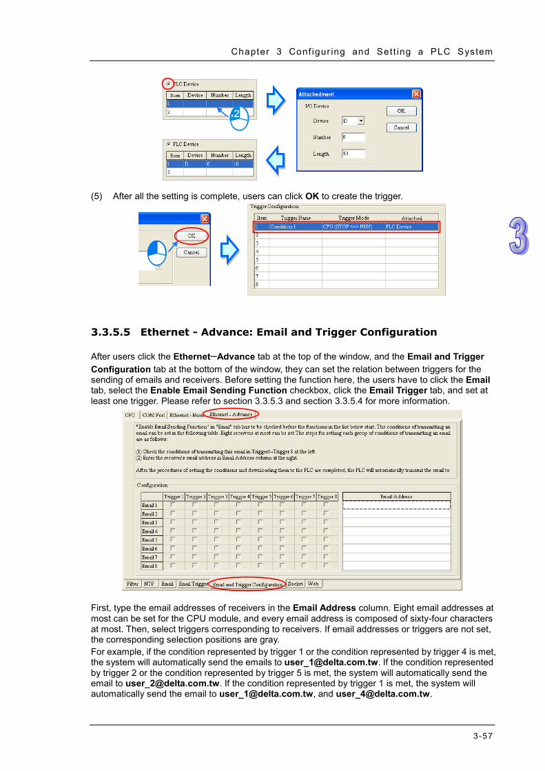
Chapter 3 Conf igur ing and Sett ing a PLC System
3-57
(5) After all the setting is complete, users can click OK to create the trigger.
3.3.5.5 Ethernet - Advance: Email and Trigger Configuration
After users click the Ethernet─Advance tab at the top of the window, and the Email and Trigger Configuration tab at the bottom of the window, they can set the relation between triggers for the sending of emails and receivers. Before setting the function here, the users have to click the Email tab, select the Enable Email Sending Function checkbox, click the Email Trigger tab, and set at least one trigger. Please refer to section 3.3.5.3 and section 3.3.5.4 for more information.
First, type the email addresses of receivers in the Email Address column. Eight email addresses at most can be set for the CPU module, and every email address is composed of sixty-four characters at most. Then, select triggers corresponding to receivers. If email addresses or triggers are not set, the corresponding selection positions are gray. For example, if the condition represented by trigger 1 or the condition represented by trigger 4 is met, the system will automatically send the emails to [email protected]. If the condition represented by trigger 2 or the condition represented by trigger 5 is met, the system will automatically send the email to [email protected]. If the condition represented by trigger 1 is met, the system will automatically send the email to [email protected], and [email protected].

ISPSoft User Manual
3-58
3.3.5.6 Ethernet - Advance: Socket
After users click the Ethernet - Advance tab at the top of the window, and the Socket tab at the bottom of the window, they can set the parameters for sockets through which data is transmitted. This function has to be used with specific applied instructions. Please refer to AH500 Programming Manual for more information. Sockets will not be introduced here. Please refer to related documents or manuals for more information about sockets.
An AH500 system supports the transmission of data between the CPU module and other CPU modules or devices by means of the creation of sockets, and supports TCP and UDP. Users can set eight TCP connections and eight UDP connections. If users want to set a TCP connection, they have to select the Enable Socket Function checkbox, and double-click an item in the TCP Socket Connection table to open the TCP Socket Configuration window. If the users want to set a UDP connection, they have to select the Enable Socket Function checkbox, and double-click an item in the UDP Socket Connection table to open the UD Socket Configuration window.

Chapter 3 Conf igur ing and Sett ing a PLC System
3-59
The parameters in the TCP Socket Configuration window are the same as the parameters in the UDP Socket Configuration window except that there is no Keep Alive Timer parameter in the UDP Socket Configuration window. The parameters in the TCP Socket Configuration window are described below.
Users can set a remote IP address.
Users can set a communication port used by the remote device for this TCP connection. The port number must be within the range between 0 and 65535.
Users can set a communication port used by the local CPU module for this connection. The port number must be within the range between 0 and 65535.
Users can set the length of data which will be sent by the local CPU module. The length must be within the range between 0 words and 500 words.
Uses can set an initial device in the CPU module where data which will be sent is stored.
Users can set the length of data which will be received by the local CPU module. The length must be within the range between 0 words and 500 words.
Uses can set an initial device in the CPU module where data which will be received is stored.
Users can set a maximum keep alive time for the connection. If no data is transmitted, and the keep alive period has elapsed, the CPU module will terminate the connection automatically.
The port number used by the local CPU module and the port number used by the remote device can not be the same, and the devices where data which will be sent is stored cannot overlap the devices where data which will be received is stored. If the IP address of the remote device is 192.168.1.100, the port number used by the remote device is 65500, and the port number used by the local CPU module is 65501, the remote device and the local CPU module can transmit data through this TCP connection. If the local CPU module wants to send 10-word data to the remote device, the data will be stored in D0~D9 before the data is sent. If the local CPU module receives 20-word data from the remote device, the data will be stored in D100~D119. If the length of data received is larger than the length set, the first 20-word data will be stored in D100~D119, and the data after the first 20-word data will be discarded. Likewise, if the length of data received is less than the length set, the data will be stored in the devices starting from D100, and the values in devices where no new data is stored will be retained. If no data is transmitted, and 60 seconds have elapsed, the CPU module will close the socket, and terminate the connection.

ISPSoft User Manual
3-60
3.3.5.7 Ethernet - Advance: Web
After users click the Ethernet - Advance tab at the top of the window, and the Web tab at the bottom of the window, they can enable the built-in web monitoring function of the CPU module.
Select the Enable Web Function checkbox, and the select a language which will be adopted in the drop-down list box. After the parameter is downloaded to the CPU module correctly, users can view the built-in web pages in the CPU module by means of a web browser.
*. Please refer to operation manuals for more information about the web monitoring function.
3.3.5.8 Ethernet - Advance: Data Exchange
The CPU module of AH5x0-EN series contains the data exchange function based on MODBUS TCP. The built-in function is enabled by clicking the Ethernet - Advance tab at the top of the window, and the Data Exchange tab at the bottom of the window as below.

Chapter 3 Conf igur ing and Sett ing a PLC System
3-61
If users open this page of the PLC Parameter Setting window for the first time, the table is blank due to no data set. A new row of data can be inserted by clicking Add. Double-click the data so that the data setting window is opened.
Set the starting mode to Program Control; PLC decides whether the set data exchange is
performed. PLC Run means that the set data exchange will be performed automatically when PLC is in RUN state. Always Enable means that the data exchange will be performed constantly when PLC is powered on.
A new data exchange table will be added in area by clicking Add. The present data exchange table selected will be moved up or down by clicking Move Up and Move Down. The present data exchange table selected will be deleted by clicking Delete. The present data exchange table selected will be copied by clicking Copy and then can be pasted to the last row.
The data exchange table is listed and explained as below.

ISPSoft User Manual
3-62
Name Description
Item The number of the block for data exchange
Enable To select whether to enable the data exchange table when the data exchange is performed.
Remote Address The target slave station address of the data exchange table
IP Address
The target IP address of the data exchange table. One IP address can be set for multiple data exchange tables.
Local Address The device address range used by the master in the data exchange table
<< / >> 「<<」: Input; the data block where the master read a slave 「>>」: Output; the data block where the master write to a slave
Remote Address
The device address range used by a slave in the data exchange table The device range will be in hexadecimal display, if the slave in the data exchange table is a user-defined MODBUS Device.
Quantity The size of the data exchange table, which is basically consistent with the result calculated from the device range.
Double click a data exchange table to be set so as to open the Item window as below. Select the checkbox of Enable to enable the data exchange table in the mode mentioned above. Remote Address is the address of the target slave for data exchange. The Shortest Update Cycle is the period for data exchange of the data exchange table. If the target device does not make any response within the time specified by Connection Timeout, that is timeout. The master can complete the read and write in a command to improve the efficiency of data exchange by selecting Support Read/write synchronization (Function code 0x17) in which the specific MODBUS function code is used. Please make sure that all devices in data exchange support MODBUS function code for read and write synchronization. Otherwise, the read and write will fail on account of the failure to identify the function codes after the command from the master is received. Device Type is the model of a slave including Delta PLC and standard MODBUS devices.

Chapter 3 Conf igur ing and Sett ing a PLC System
3-63
Input AH5x0-EN series read data from a remote device. Local Start Address: The start address of D data registers where AH5x0-EN series store data Remote Start Address: Device type and start address of the remote device to be read Quantity: Data length of input
Output AH5x0-EN series write data to a remote device. Local Start Address: The start address of D device type of the source data of AH5x0-EN series Remote Start Address: Device type and start address of the remote device to be written Quantity: Data length of output While the data exchange setup for AH5x0-EN series is conducted, the local device can only be the data register D with Word as the unit. And remote address can take Bit as the unit which may not start from 0, such as D0.3 as a remote start address. If the set data size is not a multiple of Word, the local devices will still make the data exchange via corresponding bits and the bits which are not in data exchange will keep original state. For example, if the data in remote M0~M19 is read to local data register D0~D1, the data will be stored in D0.0~D1.3 in order and D1.4~D1.15 will keep their original states.
3.3.6 Data Exchange Setup - COM
For AH5x1 series, there are additional tabs for data exchange setup in PLC Parameter Setting window, such as two COM ports or one COM port and one Ethernet port according to different models. The parameters are set on the tabs of Data Exchange Setup-COM1 and Data Exchange Setup-COM2, or Data Exchange Setup-COM and Data Exchange Setup-Ethernet for making the data exchange table of the communication port built in AH5x1 series. AH5x1 series working as the master exchanges data with the remote devices working as slaves via COM1 and COM2 based on MODBUS protocol or via Ethernet port based MODBUS TCP protocol.

ISPSoft User Manual
3-64
Set the starting mode to Program Control; PLC decides whether the set data exchange is performed. PLC Run means that the set data exchange will be performed automatically when PLC is in RUN state. Always Enable means that the data exchange will be performed constantly when PLC is powered on.
A new data exchange table will be added in area by clicking Add. The present data exchange table selected will be moved up or down by clicking Move Up and Move Down. The present data exchange table selected will be deleted by clicking Delete. The present data exchange table selected will be copied by clicking Copy and then can be pasted to the last row.
The data exchange table is listed and explained as below.
Name Description
Item The number of the block for data exchange
Enable To select whether to enable the data exchange table when the data exchange is performed.
Station Address/IP Address
The slave station address of the data exchange table, One address can be set for multiple data exchange tables. It is a station address for COM1and COM2 tabs and IP address for Ethernet tab.
Local Address The device address range used by the master in the data exchange table
<< / >> 「<<」: Input; the data block where the master read a slave 「>>」: Output; the data block where the master write to a slave
Remote Address
The device address range used by a slave in the data exchange table The device range will be in hexadecimal display, if the slave in the data exchange table is a user-defined MODBUS Device.
Quantity The size of the data exchange table, which is basically consistent with the result calculated from the device range.

Chapter 3 Conf igur ing and Sett ing a PLC System
3-65
3.3.6.1 Data Exchange Setup - COM
On the page of tab Data Exchange Setup - COM1, Data Exchange Setup - COM2, or Data Exchange Setup - COM, double click a data exchange table which is to be set to open Item window as below. Select the checkbox of Enable to enable the data exchange table in the mode mentioned above. Remote Address is the address of the target slave for data exchange. The Shortest Update Cycle is the period for data exchange of the data exchange table. If the target device does not make any response within the time specified by Connection Timeout, that is timeout. The master can complete the read and write in a command to improve the efficiency of data exchange by selecting Support Read/write synchronization (Function code 0x17) in which the specific MODBUS function code is used. Please make sure that all devices in data exchange support MODBUS function code for read and write synchronization. Otherwise, the read and write will fail on account of the failure to identify the function codes after the command from the master is received. Device Type is the model of the target slave including Delta PLC and standard MODBUS devices.
Input AH5x1-EN series read data from a remote device. Local Start Address: Device type and start address of devices where AH5x1-EN series store data; Remote Start Address: Device type and start address of the remote device to be read; Quantity: Data length of input
Output AH5x1-EN series write data to a remote device.

ISPSoft User Manual
3-66
Local Start Address: Device type and start address of the source data of AH5x1-EN series; Remote Start Address: Device type and start address of the remote device where data are to be written; Quantity: Data length of output
3.3.6.2 Data Exchange Setup - Ethernet
On the page of tab Data Exchange Setup - Ethernet, double click the data exchange table to be set so as to open the Item window as below. The settings are almost same as that for Data Exchange Setup - COM except the target slave model option in Device Type which contains Delta PLC and standard MODBUS TCP equipment as well as IP address for typing the IP of remote slaves. For other settings, refer to the content of Data Exchange Setup - COM.
Select the check box of Apply to all to the right side of The Shortest Update Cycle and
Connection Timeout and then click OK. The settings for The Shortest Update Cycle and
Connection Timeout will be written to other data tables on the tab Data Exchange Setup -
Ethernet. Users could set a data exchange table separately without selecting the check box of
Apply to all.

Chapter 3 Conf igur ing and Sett ing a PLC System
3-67
3.4 Setting the Parameters in an AHxxEMC Series CPU Module
3.4.1 Opening the PLC Parameter Setting Window
Double click the CPU icon on the system configuration area after HWCONFIG is started and the PLC Parameter Setting window will be opened automatically. The parameters to be set and window display may look different for different CPU models.
Please refer to the operation manual for the CPU module before the parameters in a CPU module are set and learn about the impact of the set parameters on the CPU module and the entire system so as to prevent from the system and personnel damages.
*. The parameter settings are not effective until they are downloaded to the CPU module. Refer to section 3.7.4 for
the download method.
The parameters are classified into several types. The users can click the primary tabs at the top of the window. Users should switch to different setting pages according to main types of parameters and their secondary tables. Parameter name, Value, Unit, Default, Minimum and Maximum are listed in the title bar in the right of the window.

ISPSoft User Manual
3-68
3.4.2 Options
3.4.2.1 Options - ID Info + System
ID Info, System Parameter, Latched Device Range and IO Interrupt under ID Info + System, click the Options tab to see these options. There are Name box where maximum 31 characters can be input and Comment box where maximum 63 characters can be input on the ID Info page. There is no special restriction on the input characters; special marks and spaces are allowed to use here. However, the users have to note that one Chinese character occupies two characters. After an ISPSoft project is created, the project name will be taken as the default name of the CPU module, and the default name of the CPU module will be attached to the model in the project management area. Users can change the default name of the CPU module in the Name box later.
Users can identify a device by means of the name of the device. When several devices are connected to one network, users can check whether a device connected to the computer is the device they expect by checking the device name. To prevent errors, if users want to download/upload the program, the system will remind the users to check the name of the CPU module and the name attached to the model in the project management area, when the name of the CPU module is different from the name attached to the model in the project management area. The parameters on System Parameter table are shown in the following window. Users could set appropriate values via a drop-down option list or type the values in the box. Clear Non-latched Device (STOP --> RUN) If the Clear Non-latched Devices checkbox is selected, the states of the non-latched devices and the values in the non-latched devices will be cleared when the CPU module begins to run. Y state (STOPRUN) When the CPU module begins to run, the states of the Y devices are OFF, retained, or restored to the states before the CPU module’s stopping running. Clear: All Y devices are set to OFF. Retain Present State: The states of the Y devices are retained. Previous State before STOP: The states of the Y devices are restored to the states before the CPU module stops. Error Log Storage Location Users set the place where the error log is stored. PLC:If the PLC option button is selected, twenty error logs at most can be stored in an AHxxEMC series CPU module. If there are more than twenty error logs, the oldest error log will be overwritten

Chapter 3 Conf igur ing and Sett ing a PLC System
3-69
by the latest error log. PLC and PLC CARD:If the PLC and PLC CARD option button is selected, and there are more than twenty error logs, the oldest error log will be moved to the memory card before the overwritten. CPU Operation during an occurrence of a Program Error If an error occurs in the program, the status of the CPU may change. Stop: CPU switches to the Stop state. Continue: CPU retains the state before any error occurs.
CPU Operation during an occurrence of a Bus Fault If an error occurs on the bus, the status of the CPU may change. Stop: CPU switches to the Stop state. Continue: CPU retains the state before any error occurs. Remote Reset Enable The function is for setting whether to allow the remote system to reset the CPU. After users select the function and download the parameter to the CPU module, they can click Format PLC Memory… on the PLC menu, and select the Reset PLC Memory (Factory Setting) option button in the Format PLC Memory window in ISPSoft. Useless: The function is not used. Use: The function is used.
Constant Communication Response Enable If this function is not enabled, commands received through the communication ports will not be processed until the scan cycle is complete. If this function is enabled, commands received through the communication ports will be processed every specific period of time. However, the scan procedure is interrupted when the system processes commands received through the communication ports. As a result, the scan time will be prolonged if this function is enabled. Please make sure that the operation of the system is not affected when this function is used. EtherCAT Node ID The node ID of EtherCAT is set exactly based on the configuration set in the software or the rotary switch of the module. Useless: ID is set according to the configuration in the software. Use: ID is set according to the rotary switch of the module. Watchdog Timeout Users can set a timeout during which the program is scanned. If the scan procedure cannot be completed within the time set for some reason, the watchdog timeout occurs, and the CPU module will be in an erroneous condition.

ISPSoft User Manual
3-70
Constant Scan Enable Users can select the Constant Scan Enable checkbox, and set a scan time. If the actual scan time is less than the setting value, the CPU module will not carry out the next scan until the setting value is reached. If the actual scan time is larger than the setting value, the CPU module will ignore the setting value, and operate according to the actual scan time. Scan Time Users type the period of scan time in the box if the preceding constant scan is enabled. User should notice that the timeout error will occur once the CPU starts to run if the set scan time is larger than Watchdog Timeout value. Interval Interrupt Time 0 Users can set interval timers to trigger the interrupts. The function is used with Timer Interrupt 0 in the work management together. Please refer to chapter 5 for more information.
Interval Interrupt Time 1 Users can set interval timers to trigger the interrupts. The function is used with Timer Interrupt 1 in the work management together. Please refer to chapter 5 for more information. Interval Interrupt Time 2 Users can set interval timers to trigger the interrupts. The function is used with Timer Interrupt 2 in the work management together. Please refer to chapter 5 for more information. Interval Interrupt Time 3 Users can set interval timers to trigger the interrupts. The function is used with Timer Interrupt 3 in the work management together. Please refer to chapter 5 for more information. Users set a range of latched devices on tab Latched Device Range. Click button to open the setting window where users can set the start and end addresses of the device. After the users click Default, the setting will be restored to the default values. After the users click Clear, the value in the box will be cleared to 0. Exit from the window by clicking OK to save the settings and Cancel to give up the settings. Tab IO Interrupt is for users to select X input points and enable the IO interrupt input function. X0.8~X0.15 will match IO interrupt 1~ IO interrupt 8 separately. Please refer to chapter 5 for more information.
3.4.2.2 Option: COM Port Setting
AHxxEMC is equipped with 2 COM ports. Users could set COM1 and COM2 parameters individually by clicking COM Port 1 Setting or COM Port 2 Setting under COM Port Setting. The setting items are same for the two COM ports.

Chapter 3 Conf igur ing and Sett ing a PLC System
3-71
Set the communication protocol of the COM port.
Users can set a station address at the communication port. A device on a network can be identified by means of the station address of the device. The station address of a device on a network can not be the same as the station address of another device on the same network.
If the communication port functions as a slave, and there are other slaves, the station address of the communication port cannot be 0. Station address 0 has the meaning of broadcasting to all slaves in a communication protocol. If a master specifies in a data packet that data must be sent to station address 0, the data will be sent to all slaves. No matter what station addresses of these slaves are, these slaves will receive the data packet.
If the sending of a command fails, the CPU module will retry the sending of the command. Users can set the number of times for sending a command in the box of Times of Auto-retry and set the time interval to retry the sending of a command in the box of Time Interval of Auto-retry when the communication fails. PLC module will make a next connection with the network every the set interval time when the communication fails.
3.4.2.3 Option- Ethernet Setting
The users can set the communication parameters for the Ethernet port in the CPU module in this page. They can refer to section 2.4.7 for more information about connecting to a CPU module through the Ethernet port on the CPU module, and refer to other related documents or manuals for more information about Ethernet. Users can set an IP addressing mode for the CPU module. If users select Static in the IP Addressing Mode drop-down list box, they can specify an IP address. If Dynamic is selected in the IP Addressing Mode drop-down list box, an IP address is assigned dynamically. 3.4.3 Data Exchange - COM1, Data Exchange - COM2 and Data
Exchange - Ethernet
After users click the tab Data Exchange - COM1, Data Exchange - COM2 and Data Exchange – Ethernet, the parameters for making the data exchange table of the communication port built in AHxxEMC series can be set. AHxxEMC series as a master exchanges data with remote devices working as slaves via COM1 and COM2 based on MODBUS protocol or via Ethernet port based on MODBUS TCP protocol.

ISPSoft User Manual
3-72
As one start mode, Program Control decides whether the set data exchange is performed.
PLC Run means that the set data exchange will be performed automatically when PLC is in RUN state. Always Enable means that the data exchange will be performed constantly when PLC is powered on.
A new data exchange table will be added in area by clicking Add. The present data exchange table selected will be moved up or down by clicking Move Up and Move Down. The present data exchange table selected will be deleted by clicking Delete. The present data exchange table selected will be copied by clicking Copy and then can be pasted to the last row.
The data exchange table is explained as below.
Name Description
Item The number of the block for data exchange
Enable To select whether to enable the data exchange table when the data exchange is performed.
Station Address/IP Address
The slave station address of the data exchange table, One address can be set for multiple data exchange tables. It is a station address for COM1and COM2 tabs and IP for Ethernet tab.
Local Address The device address range used by the master in the data exchange table
<< / >> 「<<」: Input; the data block where the master read a slave 「>>」: Output; the data block where the master write to a slave
Remote Address
The device address range used by a slave in the data exchange table The device range will be in hexadecimal display, if the slave in the data exchange table is a user-defined MODBUS Device.
Quantity The size of the data exchange table, which is basically consistent with the result calculated from the device range.
3.4.3.1 Data Exchange - COM1 and Data Exchange – COM2
On the page of tab Data Exchange - COM1 or Data Exchange - COM2, double click a data

Chapter 3 Conf igur ing and Sett ing a PLC System
3-73
exchange table which is to be set to open Item window as below. Select the checkbox of Enable to enable the data exchange table in the mode mentioned above. Remote Address is the address of the target slave for data exchange. The Shortest Update Cycle is the period for data exchange of the data exchange table. If the target device does not make any response within the time specified by Connection Timeout, that is timeout. The master can complete the read and write in a command to improve the efficiency of data exchange by selecting Support Read/write synchronization (Function code 0x17) in which the specific MODBUS function code is used. Please make sure that all devices in data exchange support MODBUS function code for read and write synchronization. Otherwise, the read and write will fail on account of the failure to identify the function codes after the command from the master is received. Device Type is the model of the target slave including Delta PLC and standard MODBUS devices.
Input AHxxEMC series read data from a remote device. Local Start Address: Device type and start address of devices where AHxxEMC series store data; Remote Start Address: Device type and start address of the remote device to be read; Quantity: Data length of input
Output AHxxEMC series write data to a remote device. Local Start Address: Device type and start address of the source data of AHxxEMC series; Remote Start Address: Device type and start address of the remote device where data are to be written; Quantity: Data length of output

ISPSoft User Manual
3-74
3.4.3.2 Data Exchange - Ethernet
On the page of tab Data Exchange - Ethernet, double click the data exchange table to be set so as to open the Item window as below. The settings are almost same as that for Data Exchange - COM1 and Data Exchange - COM2 except the target slave model option in Device Type which contains Delta PLC and standard MODBUS TCP equipment as well as IP address for typing the IP of remote slaves. For other settings, refer to the content of Data Exchange - COM1 and Data Exchange - COM2.
Select the check box of Apply to all to the right side of The Shortest Update Cycle and Connection Timeout and then click OK. The settings for The Shortest Update Cycle and Connection Timeout will be written to other data tables on the tab Data Exchange- Ethernet. Users could set data exchange tables separately without selecting the check box of Apply to all.
3.5 Setting the Parameters in an AS Series CPU Module
3.5.1 Opening the PLC Parameter Setting Window
After users double-click the CPU module in the system configuration area, the PLC Parameter Setting window will appear. The parameters which can be set vary with the models of the CPU modules.
Before the parameters in a CPU module are set, users have to refer to the operation manual for the CPU module. To prevent damage to the system or staff, the users have to

Chapter 3 Conf igur ing and Sett ing a PLC System
3-75
make sure of the effect that the parameters which are set have on the CPU module and the whole system.
*. The parameter settings are not effective until they are downloaded to the CPU module. Refer to section 3.7.4 for the download method.
The parameters are classified into several types. The users can click the primary tabs at the top of the window. Users should switch to different setting pages according to main types of parameters and their secondary tables.
3.5.2 Options
3.5.2.1 Options - System Information
System Information, System Parameter, Latched Device Range, Input Point Filter Time, Limited Point Setting and Daylight Saving Timing under System Information appear after users click the Options tab. There are only Name box where maximum 15 characters can be input and Comment box where maximum 31 characters can be input on System Information page. There is no special restriction on the input characters; special marks and spaces are all allowed to use here. However, the users have to note that a Chinese character occupies two characters. After an ISPSoft project is created, the project name will be taken as the default name of the CPU

ISPSoft User Manual
3-76
module, and the default name of the CPU module will be attached to the model in the project management area. Users can change the default name of the CPU module in the Name box later.
Users can identify a device by means of the name of the device. When several devices are connected to one network, users can check whether a device connected to the computer is the device they expect by checking the device name. To prevent errors, if users want to download/upload the program, the system will remind the users to check the name of the CPU module and the name attached to the model in the project management area, when the name of the CPU module is different from the name attached to the model in the project management area. The parameters on System Parameter table are shown in the following window. Users could set appropriate values via a drop-down option list or type the values in the box.
Clear non-latched area when RUN -->STOP If the state of the CPU module changes from RUN to Stop, the states of the non-latched devices and the values in the non-latched devices are cleared. Enable: The current states and values of devices are retained. Disable: The states and values of devices are cleared to the preset value. Y output point keep when (RUN <-> STOP) The state of Y device is set when the state of CPU is switched between RUN and STOP.

Chapter 3 Conf igur ing and Sett ing a PLC System
3-77
Off:All Y devices are set to OFF.
Retain Present State: The states of the Y devices are retained. I/O module CONFIG by Auto/Manual when Power On The actual I/O module configuration is read automatically when the CPU module is powered ON. Or the CPU module operates based on the configuration set manually by users in HWCONFIG. Auto: Operates based on actual connected modules without any module and parameters set. Manual: Operates based on the configuration set in HWCONFIG by users.
Select Action when I/O Module parameter with Manual CONFIG Different The parameter cannot be set unless the Manual option is selected in the above parameter I/O module CONFIG by Auto/Manual when Power On. Auto update: The CPU module will update its configurations based on the actual module configurations. CPU alarm: The CPU module shows a warning when an error occurs.
CPU module Stop when I/O Module No Response The parameter sets whether the CPU and other normal modules can operate constantly when there is a extension module, which does not response when offline. Stop: The CPU module stops running and gives errors. Keep Run: The CPU module and other normal modules keep running. CPU module Stop when I/O Module Occurred Error The parameter sets the method to deal with a tiny error in the extension modules. Stop: The CPU stops running and sends an error. Keep Run: The CPU keeps running but records the warning message. Setting delay time to detect I/O Module The parameter sets how long after the CPU is powered on, the I/O module and remote I/O module begin to be scanned.
Assign X Input Point Control Run/Stop The parameter sets whether one X input point controls the RUN or STOP state of the CPU. Disable: The function is closed. The state of the CPU can be changed with its DIP switch. Enable: Use the specified X input point to control and the DIP switch of the CPU can also be used.
Select X Input Point Select one X input point on the drop-down list to switch Run/Stop if the above parameter Assign X Input Point Control Run/Stop is enabled. Constant Scan Cycle Time The parameter sets the shortest constant time to complete a cycle of scan. Disable: The function is closed. Enable: The CPU starts the next scan after the waiting time reaches the setting value if the actual scan time is less than the setting value. However, the CPU will operate based on actual scan time disregarding the setting value if the actual scan time is greater than the setting value. Input Constant Time Type the cycle time value in the parameter box if the parameter Constant Scan Cycle Time is

ISPSoft User Manual
3-78
enabled. Please note if the setting value of scan time is greater than the setting value of Setting Watchdog Time, there will be a timeout error once the CPU operates. Setting Watchdog Time The parameter sets a timeout during which the program is scanned. The CPU module will send an error if the program execution exceeds the time.
Show Battery Low Voltage Error The parameter sets whether the alarm is shown when the lithium battery for the real-time clock is of low voltage or is not installed in AS300. Disable: The function is closed. Enable: There is an alarm when the lithium battery is of low voltage or not installed. Save Error history into The parameter sets the location to store error logs. PLC: The error logs are stored in PLC. Twenty error logs at most can be stored. If there are more than twenty error logs, the oldest error log will be overwritten by the latest error log. PLC & SD Card: The error logs are stored in PLC and SD card. There are more than twenty error logs, the oldest error log will be moved to the SD card before the oldest error log is overwritten.。 COM Communication Error Record The parameter sets whether to enable the error record when there is an error at COM port. Disable: The function is closed. Enable: The error record function is enabled. 1601 Timer interrupt Setting Time Base Users can set the interval of triggering 1601 timer interrupt. The function is used with Timer Interrupt 0 in the work management together. Please refer to chapter 5 for more information. 1602 Timer interrupt Setting Time Base Users can set the interval of triggering 1602 timer interrupt. The function is used with Timer Interrupt 1 in the work management together. Please refer to chapter 5 for more information. 1603 Timer interrupt Setting Time Base Users can set the interval of triggering 1603 timer interrupt. The function is used with Timer Interrupt 2 in the work management together. Please refer to chapter 5 for more information.

Chapter 3 Conf igur ing and Sett ing a PLC System
3-79
1604 Timer interrupt Setting Time Base Users can set the interval of triggering 1604 timer interrupt. The function is used with Timer Interrupt 3 in the work management together. Please refer to chapter 5 for more information. The parameters on Device Range Setting table are shown in the following window.
Set the start address and end address of this kind of devices by clicking button. Click Default button to restore to the default value. Click Clear button to clear the box content to 0. Finally, click OK to save the settings or Cancel to give up the setting and leave the dialogue box. The filter time of every input point is set on the Input Point Filter Time table. The signal will be filtered as a noise if the period of time during which an input point receives a signal less than the filter time. And users could set an appropriate filter time according to the interference state of the field environment.
X Input Point Setting Mode The parameter sets whether to set the filter time of input points or to use default settings. Default Setting: The preset filter time is used. Custom Setting: Users set the filter time of every X input point themselves. X0.0~X0.15 Input Filter Time Setting
Users could type the respective filter time of X0.0~X0.15 if Custom Setting is selected as X Input Point Setting Mode.

ISPSoft User Manual
3-80
The parameters on Limit Point Setting table set to specify input points as the positive and negative limits of axis 1~ axis 6 channels. 12 limit points can be set at most.
Axis1(Y0.0/Y0.1) Positive Limited Select~ Axis 6 (Y0.10/Y0.11) Positive Limited Select Select the rising or falling edge trigger and X input point on the drop-down list. The parameters on Daylight Saving Timing table are used to enable or disable the function of daylight saving time and set the date when the daylight saving is conducted. The clock will automatically set the daylight saving time in advance based on the period of time set after the function is enabled.
Disable/Enable D.S.T Function The parameter sets to enable or disable daylight saving time. Start date- month The parameter sets the month from which the daylight saving time starts. Start date- day The parameter sets the date on which the daylight saving time starts. End date- month The parameter sets the month in which the daylight saving time ends.

Chapter 3 Conf igur ing and Sett ing a PLC System
3-81
End date- day The parameter sets the date on which the daylight saving time ends. Saving time The parameter is used to adjust to the earlier daylight saving time with the unit of minute.
3.5.2.2 Options-COM1 Port Setting & COM2 Port Setting
AS300 series modules are equipped with one or two COM ports based on different models. COM1 and COM2 parameters are set by clicking COM1 Port Setting and COM2 Port Setting in the list on the left-side of the following window. And the specific setting items are same for the two COM ports.
Users can set a station address. A device on a network can be identified by means of the station
address of the device. The station address of a device on a network can not be the same as the station address of another device on the same network. If the communication port functions as a slave, and there are other slaves, the station address of the communication port cannot be 0. Station address 0 has the meaning of broadcasting to all slaves in a communication protocol. If a master specifies in a data packet that data must be sent to station address 0, the data will be sent to all slaves. No matter what station address of these slaves are, these slaves will receive the data packet.
Users can set the timing of getting effective for the communication port. The communication port will take effect when the CPU module changes from STOP to RUN if users select Stop --> Run. The communication port will take effect when the CPU module is powered on if users select Power on.
Users set the baud rate for the COM port. Users can select one of the preset baud rates on the drop-down menu or select custom to type a custom baud rate.
Users set the communication protocol for the COM port.
Users set a value for Delay time to Reply. The AS CPU module waits for a period of time set and then gives a reply after receiving a communication command so as to match the time when the remote device switches the mode. Users set a value for Received Data Timeout. The AS CPU module sends a communication command as a master. But it cannot receive a reply within a period of time set and that will be regarded as a timeout.

ISPSoft User Manual
3-82
3.5.2.3 Options - Ethernet Port Basic Setting
Users can enter this page by clicking Ethernet Port Basic Setting in the project list of the window. The communication parameters can be set for the Ethernet port in the CPU module in this page. Refer to section 2.4.7 for more information about connecting to a CPU module through the Ethernet port on the CPU module, and refer to other related documents or manuals for more information about Ethernet.
Mode sets the addressing mode of the IP of the CPU module. If users select Static, they can specify an IP address directly. If DHCP or BOOTP is selected, the IP address is assigned dynamically by a DHCP/BOOTP server.
3.5.2.4 Ethernet Port Advance Setting
Users can set the parameters of Ethernet Port Advance Setting under Options including IP Filter, NTP, Email, Sock1 and RTU Mapping. IP Filter sets the filter function of network devices. It is another acknowledgement mechanism to ensure the communication object is a device which is allowed by us. The function can limit the communication object. Only the devices in the IP address list are allowed to communicate with the CPU module after the IP filter function is enabled. The data packets sent from devices of other IP addresses will be discarded by the CPU module. The setting steps are shown below. Eighteen groups of IP address at most can be listed in the table.
Select IP Filter Function Enable checkbox to enable the IP filter function and type the start address

Chapter 3 Conf igur ing and Sett ing a PLC System
3-83
and end address of group 1~8 IP. Users can use NTP table to enable the CPU module and adjust time via NTP server. Relevant parameters are set here. For more information on NTP, refer to related literature and manuals.
Select NTP Client Function Enable checkbox to enable the function.
Set the address of NTP server and cycle of constant update. Take the figure above as an example. The CPU module connects to the NTP server every 30 minutes.
Select the checkbox to enable the daylight saving time.
Set the start and end month and date and time zone when the daylight saving time is enabled.
Email table is for users to set the email-related functions. The email will be sent to the set email address after the email function is enabled. Total four groups of email sending conditions and four groups of email addresses can be set.
Select Email Function Enable to enable the function and then start setting the following parameters.
Set an IP address of SMTP server. Set the COM port of SMTP server at the COM port and set the sender’s email box at local email address. Type a mail subject as the start of the subject of every email.

ISPSoft User Manual
3-84
Select Account identification checkbox to enable the function. Users can set to authenticate themselves with a user name and a password before logging in to an SMTP server.
Type the target email address of a receiver. Type a trigger name in Trigger Name box and a minimum interval in Trigger Min Cycle in the Trigger Setting table. And then select a trigger condition on the drop-down list. When the sending condition is met, the system will send an email every a period of time. But the same email will not be sent again within the set interval.
Trigger modes can be set as follows. CPU Error If an error occurs in the CPU module, the condition of triggering the sending of an email is met. Please refer to operation manuals for more information about errors occurring in CPU modules. After users select the CPU Error option button, they have to select Fatal Error Only or All Errors in the drop-down list at the right side of the option button. a) Fatal Error Only: If a fatal error occurs in the CPU module, the condition of triggering the
sending of an email is met and an email will be sent. b) All Errors: If an error occurs in the CPU module, the condition of triggering the sending of an
email is met and an email will be sent.
CPU (RUN<=>STOP) When the CPU module begins to run, or when the CPU module stops running, the condition of triggering the sending of an email is met and an email will be sent. Bit Status Change If the state of a bit device specified meets a condition set, the sending of an email will be triggered and an email will be sent. For example, if X0.0 is turned from OFF to ON, the condition of triggering the sending of an email will be met. If users want to set a condition, they can click button in the following window.

Chapter 3 Conf igur ing and Sett ing a PLC System
3-85
Device Name: Users can select a device type in the Device Name drop-down list box.
Device Number & Bit: Users can type a device address in the Device Number box. If the device type selected is X/Y, the users have to specify a bit number.
State: Users can select Rising or Falling in the State drop-down list.
Register Value Change If the value in a device specified meets a set condition, the sending of an email will be triggered and an email will be sent. For example, if the value in D0 is larger than 10, the condition of triggering the sending of an email will be met and an email will be sent. If users want to set a condition, they can they can click button in the following window.
Device Name: Users can select a device type in the Device Name drop-down list.
Device Number: Users can type a device address in the Device Number field.
State & Value: Users can set s condition of triggering the sending of an email here. Periodic Timer An email is sent periodically. How often an email is sent depends on the interval typed in the Trigger Min Cycle box in the Trigger Setting section. Where any trigger mode is set, the user message and error log related parameters will show up.
Select the Trigger User Message Enable box and then click button to the right side of Trigger User Message. Type some content as the email text in the pop-up window. If users select the Error Log Enable checkbox in the Trigger Setting table, the error log will be added to the email content automatically.

ISPSoft User Manual
3-86
The options on the drop-down menu of Trigger Attachment Mode decide whether to add an attachment to the email. Please make sure the maximum size of the email file allowed before setting an attachment. For more information, refer to relevant operation manuals. None If this option button is selected, no attachment will be inserted. File Users can select an error log in the memory card, or the system backup file in the memory card as the attachment of the email. PLC Device If this option button is selected, the system automatically retrieves the states of the devices, or the values in the devices listed in the table as the attachment when the email is sent. After this option button is selected, users can click button in the following window to open the Attachment window. Two groups of devices at most can be set. For example, if the condition is met, the values in D0~D9 will be sent as an attachment.
Select the target email address of a receiver when the condition of sending an email is met in Trigger Receiving table. And the specific email box is set in the Email section. Users can set the parameters for sockets through which data is transmitted. This function has to be used with specific applied instructions. Please refer to AH500 Programming Manual for more information. Sockets will not be introduced here. Please refer to related documents or manuals for more information about sockets. In the Socket table, users can set COM port parameters for data transmission via Ethernet. However, the function should be applied with specific API instructions. For relevant details, refer to AS series programming manual. And for the information on the socket, refer to relevant literature.

Chapter 3 Conf igur ing and Sett ing a PLC System
3-87
The system for AS series modules supports the data transmission between the CPU module and other CPU module or device via a socket as well as TCP and UDP protocols in each of which four groups of connections can be set. Users should select Socket Function Enable checkbox before any setup and then do other setting in TCP and UDP setting pages respectively.
The parameters in the TCP Socket Setting are the same as the parameters in the UDP Socket Setting except that there is no Keep Alive Timer parameter in the UDP Socket Setting. The parameters in the TCP and UDP Socket Setting are described below. Remote IP: Users can set a remote IP address. Remote Port: Users can set a communication port used by the remote device for this TCP
connection. The port number must be within the range between 0 and 65535. Local Port: Users can set a communication port used by the local CPU module for this
connection. The port number must be within the range between 0 and 65535. Send Address: Users can set the length of data which will be sent by the local CPU module.
The length must be within the range between 0 words and 500 words. Send Length: Uses can set an initial device in the CPU module where data which will be sent is
stored. Receive Address: Users can set the length of data which will be received by the local CPU

ISPSoft User Manual
3-88
module. The length must be within the range between 0 words and 500 words. Receive Length: Uses can set an initial device in the CPU module where data which will be
received is stored. Keep Alive Timer: Users can set a maximum keep alive time for the connection. If no data is
transmitted, and the keep alive period has elapsed, the CPU module will terminate the connection automatically.
The port number used by the local CPU module and the port number used by the remote device can not be the same, and the devices where data which will be sent is stored cannot overlap the devices where data which will be received is stored. If the IP address of the remote device is 192.168.1.100, the port number used by the remote device is 65500, and the port number used by the local CPU module is 65501, the remote device and the local CPU module can transmit data through this TCP connection. If the local CPU module wants to send 10-word data to the remote device, the data will be stored in D0~D9 before the data is sent. If the local CPU module receives 20-word data from the remote device, the data will be stored in D100~D119. If the length of data received is larger than the length set, the first 20-word data will be stored in D100~D119, and the data after the first 20-word data will be discarded. Likewise, if the length of data received is less than the length set, the data will be stored in the devices starting from D100, and the values in devices where no new data is stored will be retained. If no data is transmitted, and 60 seconds have elapsed, the CPU module will close the socket, and terminate the connection. In the RTU Mapping table, users can set Delta RTU-EN01 slave in connection with AS series module. The remote device can be controlled via Ethernet and 4 groups of RTU-EN01 are connectable in the network. For the setting and operation of RTU-EN01, refer to the operation manual.
Select RTU Mapping Enable checkbox to enable the function of connection between RTU module and AS series module. Set the update cycle in Cycle box and a timeout in Timeout box. It means a timeout when RTU does not give a reply within the timeout set. The data mapping between each group of RTU-EN01 and AS series module is set in the RTU Mapping section. RTU-EN01 and I/O module connected to it are set via DCISoft. For more information on DCISoft, refer to the operation manual.

Chapter 3 Conf igur ing and Sett ing a PLC System
3-89
Users can select RTU1 Enable to enable this RTU function. Each RTU can be set individually.
Users can set a station address and IP address.
Users can set RX mapping address and RX mapping length to make the digital input points of DI module connected to RTU mapped to X/M devices and length of AS series module. While, the RY mapping address and length set is used for making the digital output points of DO module mapped to Y/M devices and length of AS300 series module.
Users can set RCR Read mapping address and RCR Read mapping length to make the analog input points of AI module connected to RTU mapped to D/SR devices and length of AS300 series module. While, the RCR Write mapping address and length set is used for making the analog output points of AO module mapped to D/SR devices and length of AS300 series module.
3.5.2.5 Options - Function Card 1 Setting
The Function Card 1 Setting table is used for setting parameters of function card 1 in AS300 series CPU module, which is installed by inserting to the slot.
Users can select Auto in Card1 Detect mode box to detect the actual card model and setting

ISPSoft User Manual
3-90
or Manual to select the AS--F232/ F422/ F485/F2AD/F2DA function card which need be configured in the Manual Select Card box.
For the setting of parameters in AS--F232/ F422/ F485, refer to COM port setting in section 3.5.2.2.
At the bottom of the table in the window above, users can set F2AD to receive the signal of 0~10V or 4~20mA in F2AD Analog Input Mode box and set F2AD to send the signal of 0~10V or 4~20mA in F2DA Analog Output Mode box. The interval of F2AD sampling and average times are set in F2AD Sampling Time and Average Times boxes respectively.
3.5.2.6 Options - Function Card 2 Setting
The Function Card 2 Setting table is used for setting parameters of function card 2 in AS series CPU module, which is installed by inserting to the slot. For function card 2, AS-FCOPM in Manual Select Card box is one additional option which does not exist for function card 1. If users select AS-FCOPM card, the parameters can be set in the following window.
Users can select AS Remote Control/Delta ASD-A2 Control/CANopen DS301 in the AS-FCOPM working mode box. AS Remote Control is used for connecting AS series remote I/O. Delta ASD-A2 control is applied to the communication protocol exclusive to Delta servo products. CANopen DS301 is for the application of DS301 standard protocol.
Users can set the address of the station when CANopen DS301 is selected in the AS-FCOPM working mode box.
The remote I/O parameters can be set if Delta ASD-A2 Control is selected as AS-FCOPM working mode. AS remote module No. sets the number of remote I/O modules and each one can connect an extension module. For operation of AS remote module, refer to section 3.5.3. Select Run mode after detect remote module sets the actual connected remote module works normally or all remote modules stop running if the number of actual connected modules are inconsistent with the set number of modules. AS CPU keep or Stop when slave node dis-connected sets to only show errors or stop running and send an alarm when the remote I/O module is disconnected during operation. Remote Communication Timeout sets the timeout during which the remote I/O module does not give a reply. Auto Retry connection after Disconnected sets the times of retrying to make a connection after a timeout occurs.
Users can set the parameters Auto Retry connection after Disconnected and AS-FCOPM

Chapter 3 Conf igur ing and Sett ing a PLC System
3-91
Bit Rate under the three AS-FCOPM working modes.
3.5.3 Configuring AS-Series Remote Modules
AS series CPU module can connect remote IO modules so as to save the wiring between a device in the remote place and the controller. AS Remote Control can be selected in AS-FCOPM Working mode box and the number of AS remote module can be set in AS Remote module No. box after users select Manual in Card2 Detect Mode box and AS-FCOMPM in Manual Select Card box in Function Card 2 Setting table under Options tab.
If users set 2 units in AS Remote module No. box, there will be 2 remote modules in the system configuration area after clicking the OK button.
Users can set the remote module in the system configuration area according to the introduction such as adding, deleting, copying and moving an extension module in section 3.2.2. The actions of clicking with the mouse or dragging as well as right-clicking and selecting context menu options are the same as that for a general controller as follows. All extension modules except network modules can be configured.

ISPSoft User Manual
3-92
Likewise, users can double click to open the parameter setting window of a remote module and the extension modules connected to it. For the remote module, the start of input device range can be set as follows. Click one remote module, double click Input Device Range box in Remote Module Group 1 table and then type the device No. in the pop-up window. After the OK button is clicked, the input and output device range of the remote device will be updated and that of extension modules connected to it will be configured automatically.

Chapter 3 Conf igur ing and Sett ing a PLC System
3-93
3.5.4 Data Exchange - COM1, Data Exchange - COM2 and Data Exchange - Ethernet
After users click the tab Data Exchange-COM1, Data Exchange-COM2 or Data Exchange-Ethernet, the parameters for making the data exchange table of the communication port built in AS series can be set. AS series module can be the master and exchanges data with the slave remote devices via COM1 and COM2 based on MODBUS protocol or via Ethernet port based on MODBUS TCP protocol. Their setting windows are the same as below.

ISPSoft User Manual
3-94
When setting the start mode to Program Control, the program in the PLC decides whether the set data exchange is performed. PLC Run means that the set data exchange will be performed automatically when PLC is in a RUN state. Always Enable means that the data exchange will be performed constantly when the PLC is powered on.
A new data exchange table will be added in area by clicking Add. The present data exchange table selected will be moved up or down by clicking Move Up and Move Down. The present data exchange table selected will be deleted by clicking Delete. The present data exchange table selected will be copied by clicking Copy and then can be pasted to the last row.
The data exchange table is explained as below.
Name Description
Item The number of the block for data exchange
Enable To select whether to enable the data exchange table when the data exchange is performed.
Station Address/ IP Address
The slave station address of the data exchange table, one address can be set for multiple data exchange tables. It is a station address under COM1and COM2 tabs and IP under Ethernet tab.
Local Address The device address range used by the master in the data exchange table
<< / >> 「<<」: Input; the data block where the master read a slave 「>>」: Output; the data block where the master write to a slave
Remote Address
The device address range used by a slave in the data exchange table The device range will be in hexadecimal display, if the slave in the data exchange table is a user-defined MODBUS Device.
Quantity The size of the data exchange table, which is basically consistent with the result calculated from the device range.
3.5.4.1 Data Exchange - COM1 and Data Exchange - COM2
On the page of tab Data Exchange-COM1 or Data Exchange-COM2, double click a data exchange table which is to be set to open Item window as below. Select the checkbox of Enable to enable the data exchange table in the mode mentioned above. Remote Address is the address of the target

Chapter 3 Conf igur ing and Sett ing a PLC System
3-95
slave for data exchange. The Shortest Update Cycle is the period for data exchange of the data exchange table. If the target device does not make any response within the time specified by Connection Timeout, that is timeout. The master can complete the read and write in a command to improve the efficiency of data exchange by selecting Support Read/write synchronization (Function code 0x17) in which the specific MODBUS function code is used. Please make sure that all devices in data exchange support MODBUS function code for read and write synchronization. Otherwise, the read and write will fail on account of the failure to identify function codes after the command from the master is received. Device Type is the model of a target slave including Delta PLC and standard MODBUS devices.
Input AS series module reads data from a remote device. Local Start Address: Device type and start address of devices where AS series store data; Remote Start Address: Device type and start address of the remote device to be read; Quantity: Data length of input
Output AS series module writes data to a remote device. Local Start Address: Device type and start address of the source data of AS series; Remote Start Address: Device type and start address of the remote device where data are to be written; Quantity: Data length of output

ISPSoft User Manual
3-96
3.5.4.2 Data Exchange - Ethernet
On the page of tab Data Exchange - Ethernet, double click the data exchange table to be set so as to open the Item window as below. The settings are almost the same as that for Data Exchange - COM1 and Data Exchange - COM2 except the target slave model option in Device Type which contains Delta PLC and standard MODBUS TCP equipment as well as IP address for typing the IP of remote slaves. For other settings, refer to the content of Data Exchange - COM1 and Data Exchange - COM2.
Select the check box of Apply to all on the right side of The Shortest Update Cycle and Connection Timeout and then click OK. The settings for The Shortest Update Cycle and Connection Timeout will be written to other data tables on the tab Data Exchange - Ethernet. Users could set data exchange tables separately without selecting the check box of Apply to all.
3.6 Setting the Parameters in a Module
3.6.1 Setting the Parameters in AH5x0 and AH5x1 Modules
Users can set the parameters in every module configured in HWCONFIG. The functions and characters of every module depend on the setting of the parameters. If users want to set the parameters in a module, they can double-click the module in the system configuration area. The system will automatically open the Parameter Setting window. The setting windows of various models are a bit different.

Chapter 3 Conf igur ing and Sett ing a PLC System
3-97
The parameters are set according to the functions supported by the module. Before users set the parameters, they have to refer to AH500 Module Manual for more information. To prevent damage to the system or staff, the users have to make sure of the effect that the parameters which are set have on the module and the whole system.
There are two tabs in the setting window of AH5x0 and AH5x1 Modules. They are the MDS Information tab and the Normal Exchange Area tab. If users click the MDS Information tab, the version of the MDS document will be displayed. The number of parameters which can be set in the module and the range of setting values depend on the version of the MDS document. Besides, if the parameters in HWCONFIG in a project are created by a newer MDS document, the system will ask users to update the MDS document when the users open the HWCONFIG window in the project.
If users click the Normal Exchange Area tab, the functions to which the input/output devices assigned to the module correspond will be displayed.

ISPSoft User Manual
3-98
Users can select a parameter type at the left side of the window, and then set the parameters in the table at the right side of the window. The formats of the tables for the parameter types are the same, but the contents of the tables are different. Besides, the number of parameters which can be set and the range of setting values depend on the firmware version of the module which is set.
The description of the columns in a table is as follows. If the color of a table cell is grayed out, the cell cannot be edited. Description
The parameter names or descriptions are shown in this column.
Address Users can set data registers in this column. The parameters in the module which do not need to be updated constantly are stored in the data registers. If users specify data registers for the parameters in the module, and the parameters in HWCONFIG are downloaded to the CPU module correctly, the data registers in the CPU module are synchronized to the parameters in the module when the system operates. As a result, the users can access the module through the data registers. Accessing a module through the data registers is more efficient than accessing the module through the instruction FROM/TO. Besides, the number of data registers that a module has is limited. When users set data registers, they have to refer to the instructions for the module. As the example below shows, D3000 corresponds to the parameter CH0 Average Time in the Parameter Setting window for AH04AD-5A. After the parameters in HWCONFIG are downloaded to the CPU module, users can change the value of the parameter CH0 Average Time by changing the value in D3000 in the CPU module. But if users write a value which is not allowed by a parameter into a data register during the operation of the system, the system will restore the value in the data register and the value of the parameter to the original values.

Chapter 3 Conf igur ing and Sett ing a PLC System
3-99
*. Please refer to programming manuals for more information about the instruction FROM/TO.
If users want to set a data register, they can click in the Address cell for a parameter, and type a data register address which will be used in the Address window. Please note that a data register address which has been assigned to the module cannot be used again. If users want to delete the data register address in the Address cell for a parameter, they can open the Address window in the same way, and delete the data register address in the window.
If the color of the Address cell for a parameter is grayed out, users can not set a data register for the parameter. In the example below, the values of these parameters are binary values. The states of certain bits in the data register set in the Address cell for the first parameter correspond to these parameters. Please refer to the documents for the modules for more information about the relation between parameters and the states of the bits in data registers.
Monitor
After users click Monitor Table on the Option menu in HWCONFIG, they can access a module through the data registers in the Monitor Table window. As a result, if a data register is set for a parameter in a module, and the checkbox in the Monitor cell for the parameter is selected, the data register specified will be displayed in the Monitor Table window after the Monitor Table window is opened. The checkbox in the Monitor cell for a parameter to which no data register is assigned cannot be selected. In the example below, D3000~D3003 are assigned to the parameters, but only D3000 and D3001 are monitored. As a result, only D3000 and D3001 will be displayed in the Monitor Table window after the Monitor Table window is opened. Please refer to section 3.5.6 for more information about Monitor Table in HWCONFIG.
Initial
Users can set initial values in this column. When the parameters in HWCONFIG are downloaded, the initial values set are written into the module. Users may need to type initial values in the Initial columns for some of the parameter types, and select initial values in the Initial columns for the other parameter types. Please refer to the instructions for a module for more information about the range of values which can be set, and the processing mechanism after the downloading of the initial values.

ISPSoft User Manual
3-100
Comment After users click the Comment cell for a parameter, they can type a comment on the parameter. A comment is composed of 32 characters at most, and a Chinese character occupies two characters. The default contents of the Comment column for a parameter type are usually the same as the contents of the Description column for the parameter type.
After Default in the lower left corner of the Parameter Setting window is clicked, the values of the parameters in the module will be restored to the default values.
3.6.2 Setting the Parameters in AHxxEMC and AS Series Modules
Users can set the parameters in every module configured in HWCONFIG. The functions and characters of every module depend on the setting of the parameters. If users want to set the parameters in a module, they can double-click the module in the system configuration area. The system will automatically open the Parameter Setting window. The setting windows of various models are a bit different.

Chapter 3 Conf igur ing and Sett ing a PLC System
3-101
The parameters are set according to the functions supported by the module.
Before users set the parameters, they have to refer to Operation Manual for more information. To prevent damage to the system or staff, the users have to make sure of the effect that the parameters which are set have on the module and the whole system.
There are two tabs in the setting window of AHxxEMC and AS series modules. They are the Device Information tab and the Normal Exchange Area tab. If users click the Device Information tab, the module information, appearance and present DDF document version will be displayed. The number of parameters which can be set in the module and the range of setting values depend on the version of the DDF document. Besides, the firmware version and hardware version of the CPU module will be displayed as well when all modules are connected online.
If users click the Normal Exchange Area tab, the functions to which the input/output devices assigned to the module correspond will be displayed. Users can select a parameter type at the left side of the window, and then set the parameters in the table at the right side of the window. The formats of the tables for the parameter types are the same, but the contents of the tables are different. Besides, the number of parameters which can be set and
AS300 Series

ISPSoft User Manual
3-102
the range of setting values depend on the firmware version of the module which is set.
The descriptions of the columns in the table are as follows. If the color of a table cell is grayed out, the cell cannot be edited. Parameter name The parameter names or descriptions are shown in this column.
Value Users can set initial values in this column. When the parameters in HWCONFIG are downloaded, the initial values set are written into the module. Users may type initial values for some parameter types, or select initial values on a drop-down menu for other parameter types in the Value column. Please refer to the instructions of the module for more information about the range of values which can be set, and the processing mechanism after the initial values are downloaded.
Unit, Default, Minimum and Maximum Users can refer to the unit, default, the minimum and maximum of the parameters in the following window when setting them.
After Default button in the lower left corner of the Parameter Setting window is clicked, the values of the parameters in the module will be restored to the default values.

Chapter 3 Conf igur ing and Sett ing a PLC System
3-103
3.6.3 Exporting and Importing the Parameters in a Module
After Export File in the Parameter Setting window is clicked, the parameters in the module will be saved as a CSV file. A file which was exported previously can also be imported. Exporting the parameters in a module
Click Export File in the Parameter Setting window, select a folder in the Save in drop-down list box in the Save As window, type a filename in the File name box, and click Save.
Importing the parameters in a module Click Import File in the Parameter Setting window, select a file which will be imported in the Save As window, and click Open. The windows for importing and exporting parameters of various modules are a bit different as follows.
AH5x0 & AH5x1 series

ISPSoft User Manual
3-104
Before the parameters are imported, the system will check the file format and the module model. If the file format or the module model is not correct, the system will stop the import of the parameters. If the data registers specified in the original file exported have been used in the present configuration, different data registers will be specified in the file after the file is imported.
3.6.4 Setting the Parameters in an Intelligent Module
Delta Electronics, Inc. provides the exclusive configuration tools for some modules. Through the software, the modules can be further configured and the parameters in the modules can be further set, such as CANopen network planning and etc. If users want to set the parameters in an intelligent module, they can right-click the module in the system configuration area, and click Intelligent Module Configuration on the context menu. If the configuration and the setting of the parameters in HWCONFIG have not been saved, the system will ask the users to save the configuration and the setting before starting the corresponding software. Once the corresponding software is started, users can not perform any editing tasks in HWCONFIG before the software is closed. Some software need be installed additionally and there will be a message to remind users of installing the configuration software if the software is not installed. Please refer to instructions for software and modules for more information about the usage of the software.
AHxxEMC & AS300 series

Chapter 3 Conf igur ing and Sett ing a PLC System
3-105
3.7 Management of the Parameters in AH and AS Series Hardware and Online Diagnosis
3.7.1 Saving and Printing a Hardware Configuration
After a hardware configuration is complete, the setting in HWCONFIG can be saved with the whole project. The contents which are saved include the hardware configuration, the parameters in the modules, and the parameters in the CPU module, but do not include the parameters in the intelligent modules. The parameters in the CPU module are saved as a para file whose primary filename is the project name. The hardware configuration and the parameters in the modules are saved as an hw file whose primary filename is the project name. The files are saved in a folder in which the project (*.isp) is saved. If users want to save the setting in HWCONFIG, they can click Save on the File menu, or on the toolbar.
If users want to perform a printing task, they click Print on the File menu to open the Print Preview window. The contents which are printed only include the configuration in the configuration area. Please refer to appendix C for more information about the Print Preview window.

ISPSoft User Manual
3-106
Additional remark If the CPU module is changed in ISPSoft after the setting of the parameters in the hardware is complete, and the new CPU module can not completely support the range of devices set for the original hardware, a warning message appears when the HWCONFIG window is opened again. The problematic modules are marked with triangular error signs in HWCONFIG. These modules are in an abnormal condition. The Download function and the Online Mode function cannot be enabled. After the incorrect device addresses are modified, users can proceed with the operation. Besides, the triangular error signs will disappear after the incorrect devices addresses are modified.
3.7.2 Purchase Order
After a hardware configuration is complete, users can click PO List on the Option menu. The system will collect the hardware which are configured, and show it in a list.
After Export on the File menu in the upper left corner of the window is clicked, the list will be saved

Chapter 3 Conf igur ing and Sett ing a PLC System
3-107
as a CSV file. The data which is exported can be edited or managed through Microsoft Excel.
3.7.3 Rack Information List for AH Series
After a hardware configuration is complete, users can click Rack Information List on the File menu. The users can view the configuration in the Rack Information List window. The modules in the window are sorted according to the backplanes on which they are installed, and arranged in a hierarchical tree structure. The users can fold or unfold a rack section to increase the convenience of viewing the configuration
After Export on the File menu in the upper left corner of the window is clicked, the list will be saved as a CSV file. The data which is exported can be edited or managed through Microsoft Excel.

ISPSoft User Manual
3-108
3.7.4 Downloading/Uploading the System Parameters
The parameters set in HWCONFIG must be downloaded to the CPU module so that they can take effect. Owing to the fact that HWCONFIG adopts the communication setting in ISPSoft, users have to make sure that ISPSoft is connected to the CPU module normally before the parameters are downloaded/uploaded. Please refer to section 2.4 for more information about communication setting. If users want to download/upload the program, but the name of the CPU module is different from the name attached to the model in the project management area, the system will remind the users to check the name of the CPU module and the name attached to the model in the project management area. Downloading the system parameters
After users click Download on the Option menu, or on the toolbar, the Transfer Items window will appear. The items which will be downloaded can be selected as needed, but the items do not include the parameters in the intelligent modules. After the users click OK, the parameters will be downloaded to the CPU module.
*. For AH5x0 series, the items to be downloaded cannot be selected.
Uploading the system parameters After users click Upload on the Option menu, or on the toolbar, the system parameters in the CPU module will be uploaded to HWCONFIG. The items which will be uploaded include the hardware configuration, the parameters in the modules, and the parameters in the CPU module, but do not include the parameters in the intelligent modules.

Chapter 3 Conf igur ing and Sett ing a PLC System
3-109
For AH5x0 series, the PLC parameter setting window provides the function of uploading and downloading but only for the CPU parameters. Click to download PLC parameters and to upload PLC parameters in the upper left of the PLC parameter setting window.
All CPU parameters will be uploaded during uploading. During downloading data, users can select the parameters to be downloaded in the following window rather than downloading all settings to the CPU module. The CPU module must be in STOP state if CPU or Ethernet –Advance checkboxes are selected in the following window. And so the system will show a reminder message before the downloading starts if the CPU module is in RUN state.
*1. If the name of the CPU module is different from the name attached to the model in the project management area,
a dialog box will appear before the parameters are downloaded or uploaded. Please refer to section 3.3~3.5 for more information.
*2. HWCONFIG adopts the communication setting in ISPSoft. Please make sure that ISPSoft is connected to the CPU module normally before the parameters are downloaded/uploaded. Please refer to section 2.4 for more information.
3.7.5 I/O Scan
Users can configure modules in the way mentioned above. If users have gotten related hardware, they can install the hardware, click I/O Scan in HWCONFIG, and scan the actual hardware configuration through communication. The time of configuring the modules will be saved. Users have to make sure that ISPSoft has connected to the CPU module normally before they carry out the operation. Please refer to section 2.4 for more information about communication setting. Users can click I/O Scan on the Option menu, or on the toolbar to carry out the operation. The contents which will be scanned include the module models, the hardware configuration, and the firmware versions of the modules, but do not include the parameters in the modules and the

ISPSoft User Manual
3-110
parameters in the CPU module. After I/O Scan is clicked, the original hardware configuration and the parameter setting will be cleared. However, the parameters in the CPU module will not be affected.
After the scan is complete, the actual hardware configuration will be displayed in the system configuration area, the system will assign input/output devices to the modules, the parameters in the modules are assigned the default values.
The firmware versions of AH5x0 and AH5x1 series modules will be based on the actual firmware versions of the modules scanned. If the firmware version of a module which is scanned is higher than the firmware version of the module in the MDS document, the highest version which can be selected will be displayed in the Firmware Version drop-down list for the module, and the actual firmware version of the module will be displayed in the Comment cell for the module. For AHxxEMC and AS300 series, their firmware versions are not displayed.
*. Please refer to section 3.4.1 for more information about MDS documents and firmware versions of modules. The difference between I/O Scan and Upload can be illustrated with the following example. If I/O Scan is clicked, the hardware configuration will be scanned, and the parameters in the modules will not be scanned. If Upload is clicked, the hardware configuration in the CPU module will be read. The hardware configuration uploaded to HWCONFIG may be different from the actual hardware configuration.

Chapter 3 Conf igur ing and Sett ing a PLC System
3-111
The parameters in the hardware shown below are downloaded to the CPU module first. The parameter in AH16AN01R-5A (installed in slot 1) is as follows.
Then, AH04HC-5A installed in slot 2 is removed from the actual backplane. The BUS FAULT LED indicator on the CPU module will be ON, that is to say, the hardware configuration in the CPU is different from the actual hardware configuration. Next, I/O Scan is clicked. The scan result will be the same as the actual hardware configuration. After AH16AN01R-5A (installed in slot 1) is double-clicked to open the Parameter Setting window, users will find that the parameter in the module is assigned the default value. The value of the parameter is different from the value of the parameter previously downloaded to the CPU module, that is to say, only the hardware configuration will be scanned after I/O Scan is clicked.
Then, Upload is clicked. After the uploading is complete, users will find that the hardware configuration and the parameters in the modules which are uploaded are the same as the hardware configuration and the parameters in the modules which were previously downloaded to the CPU module. In other words, after Upload is clicked, the system parameters in the CPU module will read, and the actual hardware configuration will not be uploaded.
Next, I/O Scan is clicked, and the scan result is downloaded to the CPU module. The BUS FAULT LED indicator on the CPU module will be OFF, that is to say, the hardware configuration in the CPU module is the same as the actual hardware configuration.
3.7.6 Online Diagnosis of AH Series
Users not only can configure modules in HWCONFIG offline, but also can operate and inspect the system through the Online Mode function if ISPSoft is connected to the CPU module. Owing to the fact that HWCONFIG adopts the communication setting in ISPSoft, users have to make sure that ISPSoft is connected to the CPU module normally before the Online Mode function is enabled. Please refer to section 2.4 for more information about communication setting. If users want to enable the Online Mode function, but the name of the CPU module is different from the name

ISPSoft User Manual
3-112
attached to the model in the project management area, the system will remind the users to check the name of the CPU module and the name attached to the model in the project management area. Please refer to section 3.3~3.4 for more information.
3.7.6.1 Online Mode
(1) After users click Online Mode on the Option menu, or on the toolbar, the hardware
configuration will be in the online mode. If the users click again, the hardware configuration will not be in the online mode.
(2) Before the hardware configuration enters the online mode, the system checks whether the
hardware configuration stored in the CPU module is the same as the hardware configuration in the system configuration area. If the hardware configuration stored in the CPU module is different from the hardware configuration in the system configuration area, the system will ask users to download the hardware configuration again.
(3) After the hardware configuration enters the online mode, the statuses of the modules
displayed in the system configuration area will vary with the actual statuses of the modules. The statuses of the LED indicators on the CPU module displayed in the system configuration area are the same as the actual statuses of the LED indicators on the CPU module. The LED indicators are the RUN LED indicator, the ERROR LED indicator, and the BUS FAULT LED indicator from top to bottom.
The module is in a warning status.
The system configuration is different from the actual system configuration. (No module is installed in this slot.)
An error occurs in the module.
The module is normal. The system configuration is different from the actual system configuration. (An unknown module is installed in this slot.)
The system configuration is different from the actual system configuration. (No extension rack is scanned.)
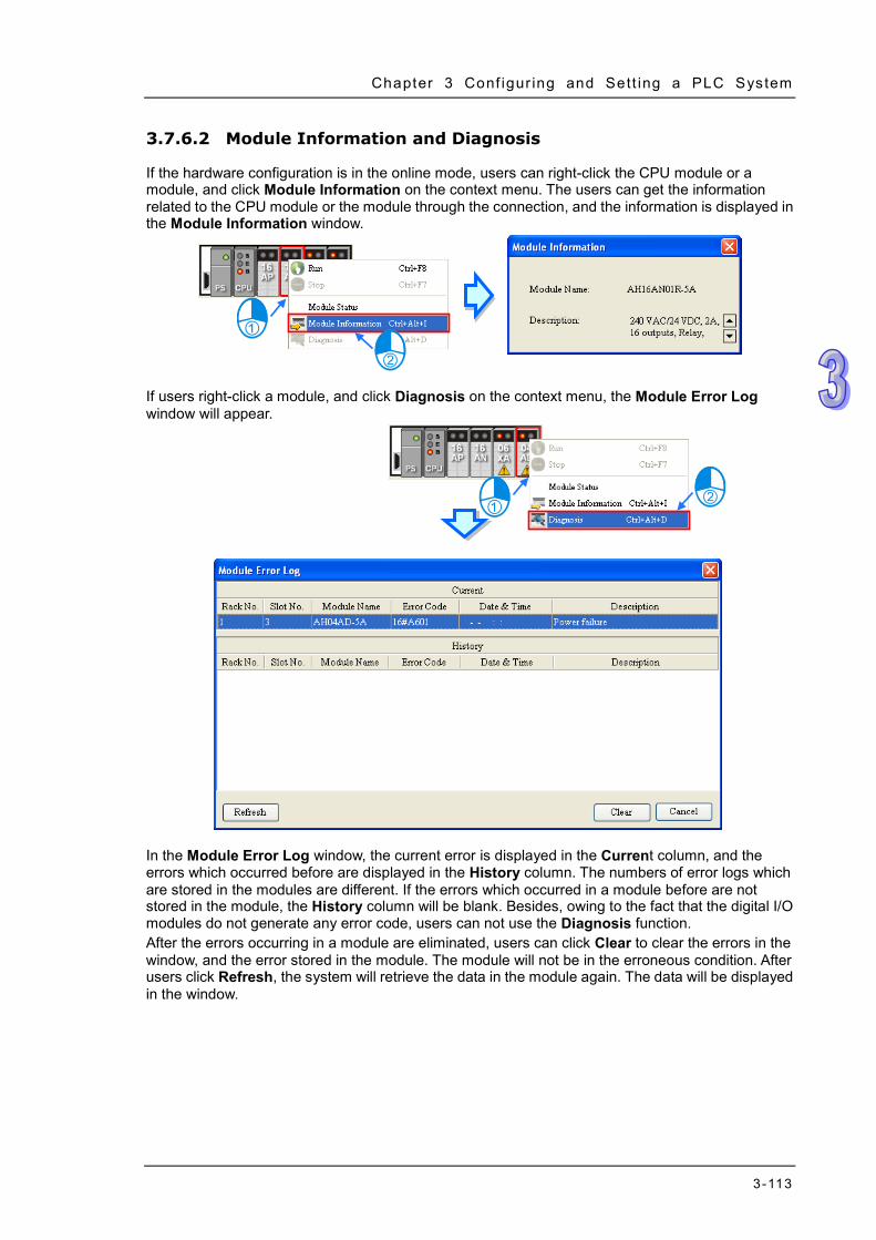
Chapter 3 Conf igur ing and Sett ing a PLC System
3-113
3.7.6.2 Module Information and Diagnosis
If the hardware configuration is in the online mode, users can right-click the CPU module or a module, and click Module Information on the context menu. The users can get the information related to the CPU module or the module through the connection, and the information is displayed in the Module Information window.
If users right-click a module, and click Diagnosis on the context menu, the Module Error Log window will appear.
In the Module Error Log window, the current error is displayed in the Current column, and the errors which occurred before are displayed in the History column. The numbers of error logs which are stored in the modules are different. If the errors which occurred in a module before are not stored in the module, the History column will be blank. Besides, owing to the fact that the digital I/O modules do not generate any error code, users can not use the Diagnosis function. After the errors occurring in a module are eliminated, users can click Clear to clear the errors in the window, and the error stored in the module. The module will not be in the erroneous condition. After users click Refresh, the system will retrieve the data in the module again. The data will be displayed in the window.

ISPSoft User Manual
3-114
3.7.6.3 Changing the Status of a Module Online
If the hardware configuration is in the online mode, users can change the status of a module, carry out a simple test.
Before the status of a module is changed, users have to make sure that the operation does not cause damage to the system or staff.
Changing the operating state of a module If the hardware configuration is in the online mode, users can right-click a module, and click Run on the context menu. The module will begin to run. When the module runs, the green light on the module is ON. If the users click Stop on the context menu, the module will stop running. Besides, if the operating state of the CPU module is changed, the operating states of all the modules are also changed.
Changing the input/output state of a module
If the modules which are configured include a digital I/O module, an analog I/O module, or a temperature measurement module, users can right-click the module, and click Module Status on the context menu. The users can monitor the input/output state of the module in the window which appears. In the window for a digital I/O module, users can right-click an input/output channel, and click Force ON or Force OFF on the context menu. Before Force ON or Force OFF on the context menus is clicked, the CPU module and the digital I/O module must run to produce the actual outputs.
Force ON: The channel selected is forced ON. Force OFF: The channel selected is forced OFF. Release: The channel selected is not forced ON/OFF. Release all: All the channels are not forced ON/OFF.
Changing the values of the parameters in a module If a module is assigned data registers, users can change the values in the data registers after the hardware configuration enters the online mode. However, on account of the design of the module, the CPU module and the module may need to run to produce the values of the parameters before the values in the data registers are changed. (1) If the hardware configuration is in the online mode, users can double-click a module to open
the Parameter Setting window, and click a parameter type which will be set at the left side of

Chapter 3 Conf igur ing and Sett ing a PLC System
3-115
the window. The users will find that the appearance of the table in the window is quite different from the appearance of the table in the offline mode.
(2) The present values of the parameters are displayed in the PV column, but they are not
updated timely. After users click in the window, the system will retrieve the present values again, and the values retrieved will be displayed in the PV column.
(3) If users want to change the values in the data registers assigned to the parameters, they can
type the setting values in the SV column. Users can only type the setting values in the SV cells for the parameters to which the data registers are assigned. If users want to change the values of parameters, they can type the setting values in the SV cells for the parameters, and click after the typing of the setting values is complete. The values of the parameters will be written into the data registers assigned to the parameters.
*. Before the value of a parameter is changed, users have to refer to the instructions for the module to make sure
of the range of values which are allowed.

ISPSoft User Manual
3-116
3.7.6.4 Monitoring Table
If the hardware configuration is in the online mode, users can view the values in the data registers in the Monitor Table window after they click Monitor Table on the Option menu. Users can not add any item to the Monitor Table window. After users select the checkboxes in the Monitor cells for parameters, the data registers assigned to the parameters will be listed in the Monitor Table window. Please refer to section 3.6.2 for more information.
*. If the setting in the Monitor column in the Parameter Setting window is changed, the setting can take effect without
having to be downloaded to the CPU module. Users can view the values in the data registers in the Monitor Table window, but they can not change the values. If users want to change the values in the data registers in the Monitor Table window, they can follow the instructions in section 3.6.1. Besides, after users click the Radix cell for a data register, they can select a method of representing the value in the data register on the drop-down list.
3.7.7 Online Diagnosis of AS Series
Users not only can configure modules in HWCONFIG offline, but also can operate and inspect the system through the Online Mode function if ISPSoft is connected to the CPU module. Owing to the fact that HWCONFIG adopts the communication settings in ISPSoft, users have to make sure that ISPSoft is connected to the CPU module normally before the Online Mode function is enabled. Please refer to section 2.4 for more information about communication setting. If users want to enable the Online Mode function, but the name of the CPU module is different from the name attached to the model in the project management area, the system will remind the users to check the name of the CPU module and the name attached to the model in the project management area.

Chapter 3 Conf igur ing and Sett ing a PLC System
3-117
Please refer to section 3.5 for more information.
Online Mode
After users click Online Mode on the Option menu, or on the toolbar, the hardware
configuration will be in the online mode. If the users click again, the hardware configuration will not be in the online mode.
Before switching to the online mode, the system checks whether the hardware configuration stored in the CPU module is the same as the hardware configuration in the system configuration area. If the hardware configuration stored in the CPU module is different from the hardware configuration in the system configuration area, the system will ask users to download the hardware configuration again. After switching to the online mode, the statuses of the modules displayed in the system configuration area will vary with the actual statuses of the modules. The statuses of the LED indicators on the CPU module displayed in the system configuration area are the same as the actual statuses of the LED indicators on the CPU module. The LED indicators are the RUN LED indicator and the ERROR LED indicator from top to bottom.
Module Information and Diagnosis
If users right-click a module, and click Diagnosis on the context menu, the Module Error Log window will appear.

ISPSoft User Manual
3-118
In the Module Error Log window, the current error is displayed in the Current column, and the errors which occurred before are displayed in the History column. The numbers of error logs which are stored in the modules are different. If the errors which occurred in a module before are not stored in the module, the History column will be blank. After the errors occurring in a module are eliminated, users can click Clear to clear the errors in the window and the errors stored in the module; the module will no longer in the erroneous condition. After users click Refresh, the system will retrieve the data in the module again. The data will be displayed in the window.
Changing the Status of a Module Online
If the hardware configuration is in the online mode, users can change the status of a module, carry out a simple test.
Before the status of a module is changed, users have to make sure that the operation does not cause damage to the system or staff.
Changing the operating state of a module
If the hardware configuration is in the online mode, users can right-click a module, and click Run on the context menu. The system including the CPU and other modules without errors and warning will begin to run. When the CPU and modules run, the green lights on modules will be ON. If the users click Stop on the context menu, the system will stop running. Being different from AH series, AS series cannot change the operating states of modules separately.

Chapter 3 Conf igur ing and Sett ing a PLC System
3-119
Changing the input/output state of a module If the hardware configurations include a digital I/O module, an analog I/O module, or a temperature measurement module, users can right-click the module, and click Module Status on the context menu. The users can monitor the input/output state of the module in the window which appears. In the window for a digital I/O module, users can right-click an input/output channel, and click Force ON or Force OFF on the context menu. Before Force ON or Force OFF on the context menus is clicked, the CPU module and the digital I/O module must run to produce the actual outputs.
Force ON: The channel selected is forced ON. Force OFF: The channel selected is forced OFF. Release: The channel selected is not forced ON/OFF. Release all: All the channels are not forced ON/OFF.

ISPSoft User Manual
3-120
3.8 Setting a RTC The RTC in a PLC can be set by a tool provided by ISPSoft. Before the real-time clock in a PLC is set, users have to make sure that ISPSoft is connected to the PLC normally. Please refer to section 2.4 for more information about communication setting. (1) After users click Set RTC on the Tools menu, the SET RTC window will appear. The date
displayed at the top of the window is the date retrieved from the PLC when the window is opened, and the time displayed at the top of the window is the time retrieved from the PLC when the window is opened.
(2) If the time on the computer’s clock is the time on the real-time clock, users can select the
Computer option button, and click OK.
(3) If users want to set the real-time clock by themselves, they can select the Custom option
button, and type a date and a time in the boxes. If users click in the box, an auxiliary tool will appear. Click OK after the setting of the real-time clock is complete

Chapter 3 Conf igur ing and Sett ing a PLC System
3-121
3.9 Setting the Memory in a PLC By means of ISPSoft, users can clear the memory, or restore the setting in the PLC to the factory setting. Users have to make sure that ISPSoft has connected to the CPU module normally before they carry out the operation. Please refer to section 2.4 for more information about communication setting. (1) After users click Format PLC Memory… on the PLC menu, the Format PLC Memory will
appear.
(2) Select the Clear All Program Memory option button, and then click OK. The system will clear the memory in the PLC.
(3) If the Reset PLC Memory (Factory Setting) option button is selected, the setting in the PLC
will be restored to the factory setting after OK is clicked. On account of the design of the PLC, after the setting in the PLC is restored to the factory setting, users may need to repower the PLC so that they can proceed with the operation.
If ISPSoft is connected to an AH series CPU module, the setting in the CPU module is not allowed to be restored to the factory setting until the Enable Remote Run checkbox in the PLC Parameter Setting window is selected and the parameters are downloaded. Please refer to section 3.3 and 3.4 for more information.

ISPSoft User Manual
3-122
MEMO

4-1
Chapter 4 Quick Start Table of Contents 4.1 Quick Start ................................................................................................ 4-2
4.1.1 Example ............................................................................................ 4-2 4.1.2 Hardware ........................................................................................... 4-2 4.1.3 Program ............................................................................................ 4-3
4.2 Procedure for Creating a Project in ISPSoft ............................................. 4-3 4.3 Creating a Project ..................................................................................... 4-4 4.4 Hardware Configuration............................................................................ 4-5
4.4.1 Configuring a Module ........................................................................ 4-5 4.4.2 Setting the Parameters in a CPU Module and a Module ................... 4-6
4.5 Creating a Program .................................................................................. 4-9 4.5.1 Adding a Ladder Diagram ................................................................. 4-9 4.5.2 Basic Editing─Creating a Contact and a Coil ................................... 4-11 4.5.3 Basic Editing─Inserting a Network and Typing an Instruction ..........4-14 4.5.4 Basic Editing─Selection of a Network and Operation .......................4-16 4.5.5 Basic Editing─Connecting a Contact in Parallel ...............................4-18 4.5.6 Basic Editing─Editing a Comment ....................................................4-19 4.5.7 Basic Editing─Inserting an Applied Instruction .................................4-20 4.5.8 Basic Editing─Creating a Comparison Contact and Typing a Constant ……………………………………………………………………………..4-22 4.5.9 Writing a Program ............................................................................4-23 4.5.10 Checking and Compiling a Program ................................................4-24
4.6 Testing and Debugging a Program ..........................................................4-24 4.6.1 Creating a Connection ......................................................................4-24 4.6.2 Downloading a Program and Parameters ........................................4-27 4.6.3 Connection Test ...............................................................................4-29

ISPSoft User Manual
4-2
4.1 Quick Start The chapter provides a simple example, and leads users to create a traditional ladder diagram in ISPSoft in a short time. However, in order to help users who are not familiar with IEC 61131-3 understand the functions provided by ISPSoft, and create a traditional ladder diagram, programming concepts related to IEC 61131-3 are not introduced in this chapter. For example, POUs, function blocks, variables, and etc. are not introduced. The concepts related to IEC 61131-3 will be introduced in the following chapters.
4.1.1 Example When the equipment operates, the parts on the conveyer are conveyed from left to right. If a sensor senses that a part is under an injector, the PLC will send a trigger signal to the injector, and the injector will injects the glue. How long the part will be injected is set externally, and is not controlled by the program in the PLC. However, the program in the PLC must be able to turn the trigger signal OFF so that the trigger signal can be sent next time. There are two injectors above the conveyer, and the two injectors inject glue in the same way. Besides, there is a sensor at the left side of the conveyer. When a part passes the sensor, the sensor value increases by one increment. If the sensor value is 100, the internal completion flag will be set to ON. The state of the flag can be used by other procedures later. However, the use of the state of the flag is not introduced in this example.
4.1.2 Hardware In this example, the AH500 series CPU module used is AHCPU530-EN, the digital I/O module used is AH16AP11R-5A, and the main backplane used is AHBP04M1-5A. The table below is an I/O allocation table.
Type ID Description Digital input X0.0 START button Digital input X0.1 STOP button Digital input X0.2 In position sensor 1 Digital input X0.3 In position sensor 2 Digital input X0.4 Counting sensor
Digital output Y0.0 Conveyer Digital output Y0.1 Trigger signal for injector 1 Digital output Y0.2 Trigger signal for injector 2

Chapter 4 Quick Star t
4-3
4.1.3 Program (1) When the START button (X0.0) is turned from OFF to ON, the internal operation flag is set to
ON, and the conveyer (Y0.0) starts to run. When the STOP button (X0.1) is turned from OFF to ON, an error occurs (the error flag is ON), the operation flag is reset to OFF, and the conveyer stops running.
(2) When in position sensor 1 (X0.2) is ON, the trigger signal for injector 1 (Y0.1) is set to ON. When in position sensor 1 is OFF, the trigger signal for injector 1 is reset to OFF.
(3) When in position sensor 2 (X0.3) is ON, the trigger signal for injector 2 (Y0.2) is set to ON. When in position sensor 2 is OFF, the trigger signal for injector 2 is reset to OFF.
(4) When the counting sensor (X0.4) is turned from OFF to ON, the sensor value increases by one increment. If the sensor value is larger than or equal to 100, the internal completion flag will be set to ON.
4.2 Procedure for Creating a Project in ISPSoft The procedure for creating a project in ISPSoft is as follow. Users can adjust the procedure according to the practical application and their habits.
Hardware configuration
Users can set the parameters such as a range of latched devices and a port number in a PLC. Besides, the users have to configure modules used with an AH500 series CPU module, and set the parameters in these modules.
Network configuration If a system used adopts network architecture, or devices need to exchange data, users can configure a network, a PLC Link, or an Ether Link easily through the network configuration tool NWCONFIG in ISPSoft.
Programming After users write a program in ISPSoft, they can compile the program. If the compiling of a program is unsuccessful, the messages in the Compile Message page can lead users to the places where errors occur to check the program code.
Test and debugging Users can download a program which is compiled, a hardware configuration, and a network configuration to a PLC. Besides, the users can test and debug the program online by means of the functions provided by ISPSoft.
Owing to the fact that the example introduced in this chapter does not discuss a network configuration, only the following procedure is carried out. The procedure will be introduced in the following section.

ISPSoft User Manual
4-4
4.3 Creating a Project After ISPSoft is started, users can click the File menu, point to New, and click New to create a new project. They can also create a new project by clicking on the toolbar after ISPSoft is started.
In the Create a New Project window, type a project name in the Project Name box and a path in the Drive/Path box, select a PLC in the drop-down list boxes of Controller Type and PLC Type, and click OK. (The PLC used in this example is AHCPU530-EN.)
After the project is created successfully, a project management area will appear at the left side of the main screen. The relation between the items listed in the project management area is represented by a hierarchical tree structure. If the project management area does not appear, the users can click Workspace on the View menu, or click on the toolbar.

Chapter 4 Quick Star t
4-5
4.4 Hardware Configuration After users double-click HWCONFIG in the project management area, the HWCONFIG window will appear.
4.4.1 Configuring a Module In the HWCONFIG window, there is an eight-slot backplane on which a CPU module and a power supply module are installed. However, the backplane used in this example is the four-slot backplane AHBP04M1-5A on which the digital I/O module AH16AP11R-5A is installed. If users want to replace the backplane, they can right-click the left side of the rack in the system configuration area, click Replace on the context menu, and double-click AHBP04M1-5A in the Rack Selection window.

ISPSoft User Manual
4-6
Unfold the Digital I/O Module section on the product list, find AH16AP11R-5A, and drag the module to a vacant slot on the backplane in the system configuration area. After the module is added successfully, the related information and the devices assigned to the module will be listed in the table at the bottom of the window.
The system automatically assigns devices to a module which is added. If the devices assigned to a module do no conform to what is expected, users can click the Input/Output Device Range cell for the module, click in the cell, and type a device address in the Manual Assignment window.
4.4.2 Setting the Parameters in a CPU Module and a Module After AH16AP11R-5A is configured, users can set the parameters in the CPU module and the parameters in the extension module. After the users double-click the CPU module or the extension module, a corresponding window will appear. After the CPU module is double-clicked, the PLC Parameter Setting window will appear. The users can click the primary tabs at the top of the window, and the secondary tables at the bottom of the window to set the parameters. In this example, the users only need to define the name of the CPU module.

Chapter 4 Quick Star t
4-7
After the users click the CPU tab at the top of the window, and the Name tab at the bottom of the window, they can type a name in the Name box. The users will find the default name in the Name box is the same as the project name. Delete the default name, type “Main_Controller” in the Name box, and click OK.
After the users double-click AH16AP11R-5A, the Parameter Setting window will appear.

ISPSoft User Manual
4-8
After the Parameter Setting window is opened, the users can view the information related to the module. The users can select the parameter type at the left side of the window, and then set the parameter in the table at the right side of the window. In this example, the default values are retained. Therefore, the step of setting the parameter in AH16AP11R-5A is skipped.
The hardware configuration is not complete until the parameters in the CPU module and AH16AP11R-5A are set. However, the configuration and the setting must be downloaded to the CPU module so that they can take effect. The configuration and the setting are saved here, and will be downloaded with the program in the project later. If the users want to save the configuration and the setting, they can click Save on the File menu, or
on the toolbar. After the configuration and the setting are saved, the users can close the HWCONFIG window.
*. Please refer to chapter 3 for more information about HWCONFIG.

Chapter 4 Quick Star t
4-9
4.5 Creating a Program The following sections will lead users to create a traditional ladder diagram in ISPSoft. The contents of the following sections include creating a POU, editing a traditional diagram, and compiling a program. The users are expected to equip themselves with the basic abilities to create a traditional ladder diagram in a short time.
4.5.1 Adding a Ladder Diagram (1) Right-click Programs in the project management area and click New….
(2) Type a program name in the POU Name box, select the Ladder Diagram (LD) option button in
the Language section, and retain the other default values. Click OK after the setting is complete. An item will be under Programs in the project management area. The item is a program organization unit (POU).

ISPSoft User Manual
4-10
(3) After the POU is added, a program editing window will appear in the main working area.
After the program editing window is opened, the corresponding toolbar will appear in the window. The functions are described below.
Icon Keyboard shortcut Function
None Switch to the Address mode
Shift+Ctrl+C Displaying/Hiding the comments on the networks
None Displaying/Hiding the commands on the devices
Shift+Ctrl+A Activating/Inactivating the network selected
Shift+Ctrl+B Adding a bookmark to the network selected or deleting a bookmark from the network selected
Shift+Ctrl+P Going to the previous bookmarked position
Shift+Ctrl+N Going to the next bookmarked position
Ctrl+I Putting a network above the network selected
Shift+Ctrl+I Putting a network under the network selected
ESC Selection
Typing an instruction Inserting a contact
Typing an instruction Inserting a coil
Typing an instruction Inserting a comparison contact
Typing an instruction Selecting a type of comparison contact
Typing an instruction Inserting a block logic instruction (NP/PN/INV/FB_NP/FB_PN)
Typing an instruction Selecting a type of block logic instruction (NP/PN/INV/FB_NP/FB_PN)
Shift+Ctrl+U Inserting an instruction or a function block *. Please refer to section 4.5.3 for more information about typing an instruction.
Local symbol table
Program editing area

Chapter 4 Quick Star t
4-11
4.5.2 Basic Editing─Creating a Contact and a Coil
(1) Click on the toolbar, and then move the mouse cursor to the red frame in network 1. The mouse cursor appears as a contact when the mouse cursor is moved to the left side of the red frame, the right side of the red frame, or the bottom of the red frame. Users can decide where to insert a contact. If a ladder diagram is edited, the mouse cursor must be near a position which is edited. Besides, an object inserted is arranged by the system automatically. Users can not move the object at will. In this example, users do not need to decide where to insert the contact. Therefore, the mouse cursor can be near the red frame, and the users can click the left mouse button.
(2) Click on the toolbar, or press Esc on the keyboard. After the contact is double-clicked, a
drop-down list will appear. The items on the drop-down list are Normally Open, Normally Close, Rising-edge Trigger, and Falling-edge Trigger. In this example, Rising-edge Trigger is selected.

ISPSoft User Manual
4-12
(3) Click the line at the right side of the contact, click on the toolbar, and move the mouse cursor to the red frame. Likewise, the mouse cursor appears as a coil when the mouse cursor is above or under the red frame. Users can decide where to insert the coil. In this example, the users do not need to decide where to insert the coil. Therefore, the mouse cursor can be near the red frame, and the users can click the left mouse button.
(4) Click on the toolbar, or press Esc on the keyboard. After the coil is double-clicked, a
drop-down list will appear. The items on the drop-down list are Out, Set, and Reset. In this example, Set is selected.

Chapter 4 Quick Star t
4-13
(5) Click ??? above the contact, type a device address in the box, and press Enter on the keyboard to jump to the next box in the network. After a device address is typed in the box, the users can press Esc on the keyboard to complete the editing. In this example, X0.0 is typed in the box for the contact, and M0 is typed in the box for the coil.
Additional remark After users click a network and press Enter on the keyboard, they can edit a box. The users can edit the next box in the network after they press Enter on the keyboard. Besides, the next network is selected after the users press Tab on the keyboard. The users can edit a box with the keyboard. After the editing is complete, the users can press Enter on the keyboard to jump to the next box. If the users want to end the editing, they can press Esc on the keyboard. If the users have declared symbols, users can type the symbols or clear the field and use the drop-down list to select the symbols which can be assigned to the object. The users can select a symbol by the mouse or the up/down key on the keyboard. Please refer to chapter 6 for more information about symbols.

ISPSoft User Manual
4-14
4.5.3 Basic Editing─Inserting a Network and Typing an Instruction
After on the toolbar is clicked, a network will be under the network selected. After on the toolbar is clicked, a network will be put above the network selected. In this example, a network is under network 1.
A contact and a coil can be created not only by clicking and on the toolbar, but also by typing instructions. (1) Click the line in network 2.
(2) Type the IL instruction “LD M0”. (The instruction is case-insensitive.) As soon as the IL
instruction is typed, a box which can be edited appears. After the typing of the IL instruction is complete, users can press Enter on the keyboard or click OK at the right side of the box.

Chapter 4 Quick Star t
4-15
(3) Type the IL instruction “OUT Y0.0”, and write the program shown below.
Additional remark A contact and a coil can be created by typing simple instructions. Please refer to the description below. (The instructions typed are case-insensitive.) Inserting a normally-open contact (contact A): “A Device address”
Inserting a normally-closed contact (contact B): “B Device address”
Inserting an output coil (OUT): “O Device address”
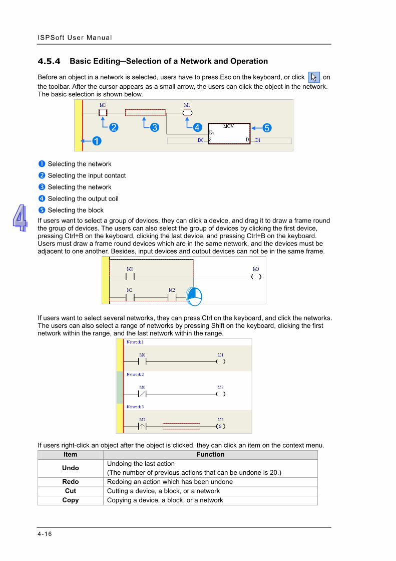
ISPSoft User Manual
4-16
4.5.4 Basic Editing─Selection of a Network and Operation
Before an object in a network is selected, users have to press Esc on the keyboard, or click on the toolbar. After the cursor appears as a small arrow, the users can click the object in the network. The basic selection is shown below.
Selecting the network
Selecting the input contact
Selecting the network
Selecting the output coil
Selecting the block If users want to select a group of devices, they can click a device, and drag it to draw a frame round the group of devices. The users can also select the group of devices by clicking the first device, pressing Ctrl+B on the keyboard, clicking the last device, and pressing Ctrl+B on the keyboard. Users must draw a frame round devices which are in the same network, and the devices must be adjacent to one another. Besides, input devices and output devices can not be in the same frame.
If users want to select several networks, they can press Ctrl on the keyboard, and click the networks. The users can also select a range of networks by pressing Shift on the keyboard, clicking the first network within the range, and the last network within the range.
If users right-click an object after the object is clicked, they can click an item on the context menu.
Item Function
Undo Undoing the last action (The number of previous actions that can be undone is 20.)
Redo Redoing an action which has been undone Cut Cutting a device, a block, or a network
Copy Copying a device, a block, or a network

Chapter 4 Quick Star t
4-17
Item Function Paste Paste an object which has been copied or cut on the present position
Paste right Pasting an object at the right side of the position selected (The object will be connected to the position selected in series.)
Paste under Pasting an object under the position selected (The object will be connected to the position selected in parallel.)
Delete Deleting a device, a block, or a network
Activate/Inactivate Network
Activating or Inactivating the network selected (The network which is inactivated is ignored when the program is compiled.)
Users can proceed with the operation in the example. (1) Select network 1, right-click network 1, and click Copy on the context menu.
(2) Select network 2, right-click network 2, and click Paste on the context menu. A copy of network
1 will be put above network 2, and network 2 will become network 3.

ISPSoft User Manual
4-18
4.5.5 Basic Editing─Connecting a Contact in Parallel
(1) Click on the toolbar, and then move the mouse cursor to the input contact in network 2. The mouse cursor will appear as a contact. Move the mouse cursor to the button of the input contact in network 2. After the mouse cursor appears as , users can click the left mouse button. A contact will be connected to the input contact in network 2 in parallel.
(2) Write the program in network 2 shown below in the way described above.
Additional remark After users select a group of contacts, they can connect a contact to the group of contacts in the way described above.

Chapter 4 Quick Star t
4-19
4.5.6 Basic Editing─Editing a Comment
(1) Make sure that on the toolbar is pressed. Click the position above a device name, type a comment in the box, and press Enter on the keyboard.
(2) Make sure that on the toolbar is pressed. Click the position under a network number, and
then type a comment in the box. If users want to start a new line of text at a specific point, they can press Shift+Enter on the keyboard. Press Enter on the keyboard after the editing is complete.
(3) Write the program shown below in the way described above.

ISPSoft User Manual
4-20
4.5.7 Basic Editing─Inserting an Applied Instruction Put network 6 under network 5, and then write the program shown below. Users can insert an applied instruction in one of the three ways described below.
Method 1
Click the position where an instruction will be inserted, type the instruction (INC in this example), and press Enter on the keyboard.
Method 2
Unfold the APIs section in the project management area, find the instruction type, and unfold the instruction type section.
Select the instruction (INC in this example) which will be inserted, and then drag it to the position where it will be inserted.

Chapter 4 Quick Star t
4-21
Method 3 Click the position where an instruction will be inserted, click on the toolbar, select the instruction (INC in this example) which will be inserted in the API/FB window, and click Insert.
After the instruction is inserted successfully, the users can assign a device address to the operand, and write the program shown below.

ISPSoft User Manual
4-22
4.5.8 Basic Editing─Creating a Comparison Contact and Typing a Constant
A comparison contact can be inserted not only in one of the three ways described in section 4.5.7, but also by means of the following steps. Users need to put network 7 under network 6, and write the program shown below.
(1) Click on the toolbar, and then select a type (>= in this example).
(2) Click on the toolbar, and then move the mouse cursor to the position where the
comparison contact will be inserted. The mouse cursor appears as a comparison contact when the mosue is moved to the left side of the red frame, the right side of the red frame, or the bottom of the red frame. The users can decide where to insert the comparison contact. After the users decided on a position, they can click the left mouse button to insert the comparison contact.
Write the program shown below in the way described above. In WPLSoft, a decimal value is preceded by K, and a hexadecimal value is preceded by H. If users want to type a decimal value in ISPSoft, they can type it directly. If users wan to type a hexadeicmal value in ISPSoft, they have to type “16#” and the hexadecimal value, e.g. 16#7FFF. In ISPSoft, an octal value is preceded by 8#, and a binary value is preceded by 2#.

Chapter 4 Quick Star t
4-23
4.5.9 Writing a Program The creation of a traditional ladder diagram in ISPSoft has been introduced. Users can write the program shown below in the way described in the previous sections. Owning to the fact that the program has not been compiled, the mother line at the left side of the ladder diagram is red during the writing of the program. The following sections will introduce how to compile the program, and how to download the program which has been compiled to the CPU module to test the program.
*1. The program above is saved in the folder denoted by …\ISPSoft x.xx\Project\Example\Gluing_System_C. *2. Please refer to chapter 10 for more information about creating a ladder diagram.

ISPSoft User Manual
4-24
4.5.10 Checking and Compiling a Program After users write a program, they can check the syntax of the programming language or compile the program. The syntax and the structure in the present window will be checked after the Check function is enabled. The whole project will be checked after the Compile function is enabled. If there is no error in the project, an execution code will be generated automatically. After the program is compiled successfully, the mother line at the left side of the ladder diagram will become black. Check
Click Check on the Compile menu, or on the toolbar.
Compile
Click Compile on the Compile menu, or on the toolbar.
After the check is complete, the Compile Message page shows the result related to the check. If there is any error in the project, the Compile Message page will show the related message. After the message is clicked, the system will automatically lead users to the place where the error occurs. The users can enable the Check function or the Compile function after the error is eliminated.
4.6 Testing and Debugging a Program
4.6.1 Creating a Connection Before a program and parameters are downloaded to a PLC or monitored online, ISPSoft must be connected to the PLC. In this example, ISPSoft is connected to the CPU module AHCPU530-EN through a USB cable. Please refer to section 2.4 for more information about connecting ISPSoft to a PLC in other ways. Please refer to operation manuals for more information about wiring.

Chapter 4 Quick Star t
4-25
Those who have connected ISPSoft to a PLC successfully in accordance with the contents of section 2.4 can skip this section. (1) Install the modules on the main backplane in accordance with the hardware configuration in
HWCONFIG. Make sure that the wiring is correct, and then power the CPU module. (2) Connect the CPU module to the computer through a USB cable. If the USB driver for the
AH500 series CPU module has been installed on the computer, Delta PLC will appear in the Device Manager Window, and a port number will be assigned to Delta PLC. Please refer to appendix A for more information about installing a USB driver.
(3) Make sure that COMMGR is started, and the icon representing COMMGR is displayed on the system tray. If the icon representing COMMGR is not displayed on the system tray, users can start COMMGR by clicking the shortcut on the Start menu (Start>Programs>Delta Industrial Automation>Communication>COMMGR).
(4) Double-click the icon representing COMMGR on the system tray to open the COMMGR
window. Click Add in the COMMGR window to create a driver.
(5) Set the parameters in the Driver Properties window, and then click OK.

ISPSoft User Manual
4-26
Type a driver name in the Driver Name box. Select USB (Virtual COM) in the Type drop-down list box in the Connection Setup section.
Select a communication port in the COM Port drop-down list box. If the first two steps are complete, the PLC which is connected and its communication port will be displayed in the COM Port drop-down list box.
Users can select the number of times the sending of a command is retried if a connection error occurs in the Time of Auto-retry box, and select an interval of retrying the sending of a command in the Time Interval of Auto-retry box.
(6) After the status of the driver displayed in the window becomes OK, the window can be closed.
The icon representing COMMGR will still be displayed on the system tray.
(7) Start ISPSoft, and then click Communication Settings… on the Tools menu. In the
Communication Setting window, select the driver which has been created in the Driver drop-down list box, appear, and select 0 in the Station Address drop-down list box, and click OK. The information about the driver will be displayed in the status bar in ISPSoft.

Chapter 4 Quick Star t
4-27
(8) Click System Information on the PLC menu. ISPSoft will retrieve related information from the PLC. If the computer communicates with the CPU module normally, the related information retrieved from the PLC will be displayed in the System Information window.
4.6.2 Downloading a Program and Parameters
If ISPSoft is connected to a PLC normally, the parameters and the program in the project can be downloaded to the PLC. First, start ISPSoft and open the project created in the previous sections. In this example, two types of parameters are downloaded to the CPU module. They are the hardware configuration and the program. Downloading the hardware configuration
(1) Double-click HWCONFIG in the project management area to open the HWCONFIG window.
(2) The hardware configuration is displayed in the window. Before the hardware configuration is
downloaded to the CPU module, users have to make sure that the actual hardware configuration is the same as the hardware configuration in the window.

ISPSoft User Manual
4-28
(3) After the users click Download on the Option menu, or on the toolbar, the Transfer
Items window will appear. The hardware configuration will be downloaded to the CPU module after OK is clicked.
(4) After the hardware configuration is downloaded to the CPU module successfully, the BUS
FAULT LED indicator on the CPU module will be OFF. The users can close the HWCONFIG window. If the BUS FAULT LED indicator on the CPU module is still ON or blinking, the CPU module is in an abnormal state. Please make sure that the actual hardware configuration is the same as the hardware configuration in the HWCONFIG window again, or refer to the operation manual for more information about eliminating the error. Please refer to chapter 3 for more information about HWCONFIG.
Downloading the program After the program is compiled successfully, the users can click the PLC menu, point to Transfer, and click Download. The users can also click on the toolbar after the program is compiled successfully. Select the Program and related Comments checkboxes in the Transfer Setup window so that the program in the CPU module can be uploaded later, and then click OK.

Chapter 4 Quick Star t
4-29
4.6.3 Connection Test
After a program is downloaded to a PLC, users can monitor the execution status of the PLC through ISPSoft. There are two monitoring modes that ISPSoft provide. One is the device monitoring mode, and the other is the program monitoring mode.
Monitoring mode Description
Device monitoring mode
Users can monitor the statuses of the devices in the PLC through the monitoring table. In this mode, ISPSoft only needs to update the statuses of the devices. The present program in ISPSoft does not need to be the same as the program in the PLC.
Program monitoring mode
In this mode, the operating status of the program is displayed in the program editing window. As a result, the present program in ISPSoft must be the same as the program in the PLC.
*. The device monitoring function can be enabled independently. However, if the program monitoring function is enabled, the device monitoring function is also enabled.
After users click Online Mode on the PLC menu, or on the toolbar, the online monitoring function will be enabled. The system will also enable the device monitoring mode and the program monitoring mode.

ISPSoft User Manual
4-30
In the online monitoring mode, users can view the present scan time, the communication status, and the status of the PLC in the status bar in ISPSoft.
Besides, the present statuses of the devices will be displayed in the original program editing window after the program monitoring function is enabled.
Users can change the operating status of a PLC by the RUN/STOP switch on the PLC. They can also change the operating status of the PLC through the functions provided by ISPSoft. After users click Run on the PLC menu or on the toolbar, the PLC will begin to run. The PLC will stop running after Stop on the PLC menu or on the toolbar is clicked.
In the online monitoring mode, users can select a device, right-click the device, and click an item on the context menu. During a test, users can change the status of a device or the value in a device by clicking an item on the context menu.
Before the status of a device is changed, users have to make sure that the operation does not cause damage to the system or staff.

Chapter 4 Quick Star t
4-31
The items on the context menu are described below. Force on the context menu only applies to input contacts and output contacts.
Item Description Set On Setting the contact selected to ON Set Off Setting the contact selected to OFF
Rising-edge Trigger No matter what the state of the contact selected is, the system set the contact to OFF, and then set it to ON.
Falling-edge Trigger No matter what the state of the contact selected is, the system set the contact to ON, and then set it to OFF.
Force Forcing an input contact or output contact ON or OFF
Force Device List Forcing several input contacts or output contacts in the tables ON or OFF
If users want to change the value in a device, they can click the device, right-click the device, click Change Present Value on the context menu, and set a present value in the Enter Present Value window.
The Enter Present Value window is described below.

ISPSoft User Manual
4-32
Message
Users can type a value in the Present Value box.
Name of a device or a symbol whose present value will be changed
Users can type a 16-bit value or a 32-bit value.
Value change history (Format: Device name Value)
In the binary mode, users can set the states of the bits through the mouse.
The setting values will be applied after OK is clicked. The window will be closed after Cancel is clicked.
Users can display or hide the binary mode. In this example, X0.0~X0.15 and Y0.0~Y0.15 are input devices and output devices assigned to the digital I/O module AH16AP11R-5A. After the parameters in the hardware are downloaded to the CPU module, the states of X0.0~X0.15 will be the same as the states of the inputs on the actual module. Even if users set X0.0~X0.15 to ON or OFF in the program editing window, the states of X0.0~X0.15 will be updated by the actual input signals.
However, an input contact can be forced ON or OFF during a test. Users can click an input contact or output contact which will be set, right-click the contact, point to Force on the context menu, and select On (X/Y), Off (X/Y), Release (X/Y), or Release All. If an input contact or output contact is forced ON or OFF, a lock symbol will appear at the left side of the contact.

Chapter 4 Quick Star t
4-33
Force Description On (X/Y) Forcing the input contact or output contact selected ON Off (X/Y) Forcing the input contact or output contact selected OFF
Release (X/Y) Releasing the contact from the locked state Release All Releasing all the contacts from the locked states
If an output contact in the program is forced ON or OFF, the output state of this contact will not be affected by the program execution result.
*. If the online monitoring function is disabled, the contacts will not be automatically released from the locked states. As a result, users have to check whether the contacts need to be released from the locked states after the test is complete.
There are two ways to create a monitoring table. Users can create a monitoring table online or offline. Method 1
Click New Devices Table on the PLC menu, or on the toolbar.
Method 2
Right-click Device Monitoring Table in the project management area and click Add.
Type a table name in the Add Monitor Table window, and then click OK. An item will be under Device Monitor Table in the project management area. If users want to open the monitoring table, they can double-click the item. Besides, the users can create several monitoring tables in the project, and the monitoring tables created will be saved with the project.

ISPSoft User Manual
4-34
After the item is double-clicked, a window will appear. The users can add items which will be monitored to the window. If the users want to add an item to the window, they have to double-click the blank in the monitoring table, or type a device name directly, and type a start address and the number of devices which will be monitored in the Device Monitor Input window. Please notice that 100 items at most can be added to a monitoring table.
The users can press Insert on the keyboard to switch between inserting an item in the monitoring table and replacing an item in the monitoring table. The mode which is selected is displayed in the status bar in ISPSoft. If the insertion mode is selected, the item added will be above the item selected in the monitoring table. If the replacement mode is selected, the item added will overwrite the item selected in the monitoring table.
If the users want to hide certain columns in the monitoring table, they can right-click the monitoring table, point to Set the Fields, and unselect certain items. After an item is unselected, the corresponding column will disappear.

Chapter 4 Quick Star t
4-35
The description of the columns in the monitoring table is as follows.
Column Description Source The source of a symbol Identifier The identifier of a symbol Device name The name of a device monitored Status If a bit device or a contact is monitored, the state will be ON or OFF. Data type If a symbol is monitored, the data type of the symbol will be displayed. Value (16 bits) In the online mode, a 16-bit value is displayed. Value (32 bits) In the online mode, a 32-bit value is displayed. Float In the online mode, a 32-bit floating-point number is displayed. Radix Users can select a format in which a value is represented. Comment The comments on a device or the comment on a symbol is displayed.
After the monitoring table is created, the users can monitor the items in the monitoring table in the online mode. Besides, after the users right-click an item in the monitoring table in the online mode, a context menu which is the same as the context menu which will after a device in the program editing window is clicked will appear. The users can change the state of the item or the value in the item by clicking an item on this context menu.
The program created in this chapter can be tested and debugged through the monitoring table created in this section. Please refer to chapter 17 for more information about testing and debugging a program.

ISPSoft User Manual
4-36
MEMO

5-1
Chapter 5 Program Organization Units and Tasks
Table of Contents 5.1 Program Organization Units and Tasks .................................................... 5-2 5.2 Program Organization Units ..................................................................... 5-3
5.2.1 Program Architecture and Types ....................................................... 5-3 5.2.2 POUs in ISPSoft ................................................................................ 5-3
5.3 Tasks ........................................................................................................ 5-5 5.3.1 Managing the Tasks in ISPSoft ......................................................... 5-5 5.3.2 Tasks in the Project Management Area ............................................ 5-5 5.3.3 Executing the POUs Assigned to a Task ........................................... 5-6
5.4 Managing a POU ...................................................................................... 5-9 5.4.1 Creating and Setting a POU .............................................................. 5-9 5.4.2 Enabling a POU................................................................................5-12 5.4.3 Deleting and Copying a POU ...........................................................5-12 5.4.4 Setting and Unlocking a POU Password ..........................................5-14 5.4.5 Exporting a POU of the Program Type .............................................5-15 5.4.6 Importing a POU of the Program Type .............................................5-16 5.4.7 Exporting a POU of the Function Block Type ...................................5-17 5.4.8 Importing a POU of the Function Block Type ...................................5-18
5.5 Managing Tasks ......................................................................................5-19 5.5.1 Setting the Property of a Task and the Condition of an Interrupt ......5-21 5.5.2 Assigning a POU to a Task ..............................................................5-23 5.5.3 Arranging the POUs .........................................................................5-24
5.6 Example ..................................................................................................5-25 5.6.1 Writing a Program by Means of IEC 61131-3 ...................................5-25 5.6.2 Example of an Interrupt Subroutine in a DVP Series PLC ................5-29 5.6.3 Example of an Interrupt Subroutine in an AH500 Series CPU Module ……………………………………………………………………………..5-35

ISPSoft User Manual
5-2
5.1 Program Organization Units and Tasks Program organization units (POUs) and tasks are important programming concepts related to IEC 61131-3. They upgrade programming from traditional program writing to project management. The difference between traditional ladder diagrams and IEC 61131-3 is described below.
Traditional ladder diagram IEC 61131-3
Main program
1. A single program is divided into several independent program organization units.
2. A program organization unit which has been created is assigned to a cyclic task.
General Subroutine 1. A subroutine is a function block. 2. A function block which has been created can be called by a
program organization unit.
Interrupt subroutine
1. Different interrupt subroutines are independent program organization units.
2. A program organization unit which has been created is assigned to an interrupt task.
Traditional ladder diagrams and IEC 61131-3 are represented by the following architectures. In the classic architecture, users write a source code. In the IEC 61131-3 architecture, a program is divided into several program organization units. Every program organization unit can be developed independently, and can be assigned a task.
If a control system reaches a certain scale, the internal control procedures will be quite complex, and the relation between the procedures will be closer. If the classic architecture is adopted, a lot of time and manpower must be invaded in developing and maintaining a program. However, in the IEC 61131-3 architecture, the program organization units are reusable and modular. Besides, the program organization units can be integrated easily by means of the management of the tasks. The concepts related to program organization units and tasks will be introduced in the following section.

Chapter 5 Program Organizat ion Units and Tasks
5-3
5.2 Program Organization Units
5.2.1 Program Architecture and Types
Program organization units are basic elements of a program in a PLC. They are different from a traditional program in a PLC. The characteristic of the program architecture introduced by IEC 61131-3 is that a program is divided into several units. These units are called program organization units. In the classic architecture, a source code for a PLC is composed of all procedures, including subroutines. If the size of a program becomes larger, the maintenance of the program and the debugging of the program will be a burden. In the IEC 61131-3 architecture, a program is divided into several units according to the functions or characteristics. It is convenient to develop and maintain a program. Besides, owing to the fact that program organization units are modular, different program organization units can be developed by different designers. It benefits the distribution of manpower and the execution of the project. There are two types of POUs in ISPSoft. They are programs (PROGs) and function blocks (FBs). Program (PROG)
A POU of the program type plays a role according to the task to which it is assigned. If a program POU is assigned to a cyclic task, the POU of the program type acts as a main program. If the POU of the program type is assigned to an interrupt task, the POU of the program type acts as a subroutine. Besides, a POU of the program type can call a function block (FB).
Function block (FB) A static symbol can be declared in a function block (FB). As a result, the value of the symbol after an operation can be retained. Owing to the fact that the operation is performed on the value memorized in the function block and an input value, the output values may be different even if the input values are the same. Besides, a function block can call another function block.
The relation among POUs is shown below. A function (FC) is a type of POU. Owing to the fact that ISPSoft currently does not support Function POU, this part will not be covered in this chapter.
5.2.2 POUs in ISPSoft
All POUs created by users are listed in the program management area. The POUs of the program type and the POUs of the function block type are managed separately. Besides, the programming language in which a POU is written determines the icon representing the POU, and the information about the POU is put at the end of the POU name. After a POU in the project management area is double-clicked, a POU editing window will appear. The POU editing window is composed of two parts. A table of local symbols is at the upper part of the window, and the body of a program is at the lower part of the window. Besides, the editing

ISPSoft User Manual
5-4
environment at the lower part of the window varies with the programming language used. Please refer to the following sections for more information about symbol tables and program editing.
The icons representing POUs are described below.
Icon Description The POU is a ladder diagram (LD).
The POU is an instruction list (IL).
The POU is a function block diagram (FBD).
The POU is a structured text (ST).
The POU is a sequential function chart (SFC).
The POU is a continuous function chart (CFC).
If the icon representing a POU is gray, the POU is disabled. A POU which is disabled is skipped when the program is compiled, and is not executed.
If the icon representing a POU is marked with a red cross, the POU is not assigned to any task. A POU which is not assigned to any task is skipped when the program is compiled, and is not executed.
*. Please refer to section 5.4.2 for more information about enabling a POU. Please refer to the following section for more information about tasks.

Chapter 5 Program Organizat ion Units and Tasks
5-5
5.3 Tasks Every POU of the program type is assigned to a specific task. The tasks determine the order in which the POUs of the program type are executed or enabled. In other words, every POU of the program type is like a basketball player, and the tasks are the roles that the POUs play.
5.3.1 Managing the Tasks in ISPSoft
In ISPSoft, not all the POUs of the program type in the project are executed. A POU of the program type will be executed after it is assigned to a task, and the task determined how the POU is executed. If a POU is not assigned to a task, the POU will be taken as a general source code and will be saved with the project, but not to be translated into an execution code. Besides, only POUs of the program type need to be assigned to tasks, and function blocks are called by POUs. The characteristic of the IEC 61131-3 architecture is that a program is divided into several POUs which can be developed independently. When all POUs are compiled, they are rearranged and combined into an execution code which can be scanned step by step. The POUs are rearranged and combined according to the tasks to which the POUs are assigned. In ISPSoft, a POU of the program type is assigned to a task. However, more than one POU can be assigned to the same task, and the order in which these POUs are executed can be specified. Besides, after users add a POU of the program type, they must assign it to a default task. There are three types of tasks. They are cyclic tasks, timed interrupt tasks, and conditional interrupt tasks. Cyclic task
A POU assigned to a cyclic task is scanned back and forth. Owning to the fact that there is only one cyclic task in a project for a DVP series PLC, the POUs which will be scanned cyclically are assigned to this cyclic task. However, there are 32 cyclic tasks in a project for an AH500 series CPU module. These cyclic tasks are numbered from 0 to 31. The smaller the task number is, the earlier the task is executed. Besides, AH500 series CPU modules support the applied instructions (TKON and TKOFF) which control tasks. Users can enable or disable a task during the operation of an AH500 series CPU module. A POU is which a sequential function chart can only be assigned to a cyclic task. It can not be assigned to an interrupt task.
Timed interrupt task A POU of the program type which is assigned to a timed interrupt task is like a timed interrupt subroutine. If the time when timed interrupts should occur is reached, the POUs assigned to the timed interrupt task will be executed in order. Besides, the number of timed interrupt tasks depends on a PLC selected. The number of interrupt sources that a PLC supports is the number of timed interrupt tasks that the system has.
Conditional interrupt task There are several types of conditional interrupt tasks. For example, external interrupts, I/O interrupts, counting interrupts, and etc. Different PLCs provide different conditional interrupt tasks. Users have to make sure of the conditional interrupt tasks which are supported by the PLC before they assign the POUs of the program type to tasks. A POU of the program type which is assigned to a conditional interrupt task is like an interrupt subroutine. If the condition of an interrupt is met, e.g. the value of a counter reaches the setting value, the POUs assigned the interrupt task will be executed in order.
5.3.2 Tasks in the Project Management Area
The POUs which are assigned to tasks are listed in the Tasks section in the project management area, and the POUs which are not assigned to tasks are not listed in the Tasks section. The order in which the POUs listed in a task section are arranged is the order in which the POUs are executed. Take the project for an AH500 series CPU module below for example. There are 9 POUs of the program type. The assignment of the POUs of the program type to tasks is as follows.

ISPSoft User Manual
5-6
Task name POU Execution
Not assigned Prog2 and Prog3 Owning to the fact that Prog2 and Prog3 are not assigned to tasks, Prog2 and Prog3 are not executed.
Cyclic (0) Prog6 and Prog4 The smaller the task number is, the earlier the task is executed. As a result, the order in which Prog6, Prog4, Prog5, and Prog7 are scanned is Prog6Prog4Prog5 Prog7. Cyclic (1) Prog5 and Prog7
I/O interrupt (0) Prog1 If the condition of the interrupt is met, Prog1 will be executed once.
Timed interrupt 1 (253) Prog8 and Prog9 Timed interrupt 1 is triggered every specific period of time. The order in which Pog8 and Prog9 are executed is Prog8Prog9.
*. The setting of the condition for an interrupt will be introduced in section 5.5. Please refer to instructions for PLCs for more information.
Additional remark If users want to enable an interrupt function, they must insert the applied instruction EI in the cyclic program so that the interrupt subroutine can be executed normally.
5.3.3 Executing the POUs Assigned to a Task
More one POU can be assigned to the same task, and the order in which the POUs listed in a task section in the project management area are arranged is the order in which the POUs are executed. Please refer to the following example. There are four POUs in the project. These POUs are described below.
Task name
POUs assigned to the task
POUs which are not assigned to tasks

Chapter 5 Program Organizat ion Units and Tasks
5-7
POU name Description Prog0 When M0 is ON, the value in D0 is 0. Prog1 When M0 is ON, the value in D0 is 1. Prog2 When M0 is ON, the value in D0 is 2.
OUTPUT When M0 is ON, the value in Y0 is the value in D0.
The programs in the POUs are as follows.
Suppose the four POUs of the program type are assigned to cyclic task (0). The arrangement of the POUs is shown below. The order in which these POUs are executed is Prog0Prog1Prog2OUTPUT. The value in D0 in OUTPUT depends on the program in Prog2. When M0 is ON, the value in D0 in OUTPUT is 2. After the value in D0 is transferred to Y0, the value in Y0 will be 2. In other words, Y0.1 will be ON after a scan cycle is complete. The equivalent program is shown below.

ISPSoft User Manual
5-8
If Prog2 is moved above Prog1, and Prog0 is removed from the Cyclic (0) section, the program in Prog0 will not be translated into an execution code, and the order in which the POUs are listed in the Cyclic (0) section will be Prog2Prog1OUTPUT. The value in D0 in OUTPUT depends on the program in Prog1. When M0 is ON, the value in Y0 is 1. In other words, Y0.0 will be ON after a scan cycle is complete.

Chapter 5 Program Organizat ion Units and Tasks
5-9
5.4 Managing a POU
5.4.1 Creating and Setting a POU
(1) If users want to create a POU of the program type, they have to right-click Programs in the project management area and click New…. If users want to create a POU of the function block type, they have to right-click Function Blocks in the project management area and click New…. Adding a POU of the program type
Adding a POU of the function block type
(2) The users have to set the attributes of the POU added in the window which appears. The
attributes of the POU of the program type are slightly different from those of the POU of the function block type, and they are described below.
POU Name: Users can type a POU name in this box.
(a) Special marks and spaces can not be used. For example, *, #, ?, \, %, @, and etc. can not be used.

ISPSoft User Manual
5-10
(b) A POU name is composed of thirty characters at most. Users have to notice that a Chinese character occupies two characters.
(c) Underlines can be used, but they can not be used continuously or put at the end of a POU name. For example, “POU_1” is a legal name, but “POU__1” and “POU_1_” are illegal names.
(d) If the POU created is a POU of the function block type, and the POU name begins with “P0_” or “P1_”, P0 or P1 will be assigned to the function block after the program is compiled.
Task: If the POU created is a POU of the program type, users have to assign the POU to a
task.
Password: If users want to set a password, they have to type the same passwords in the
two boxes. English letters, numerical digits, and special marks can be typed in the boxes.
Language: Users have to select a programming language in which the POU is written.
Comment: Users can type a comment on the POU in this box.
*. If the POU created is a POU of the program type, the Active checkbox will be in the window. The function of the
Active checkbox will be introduced in section 5.4.2.
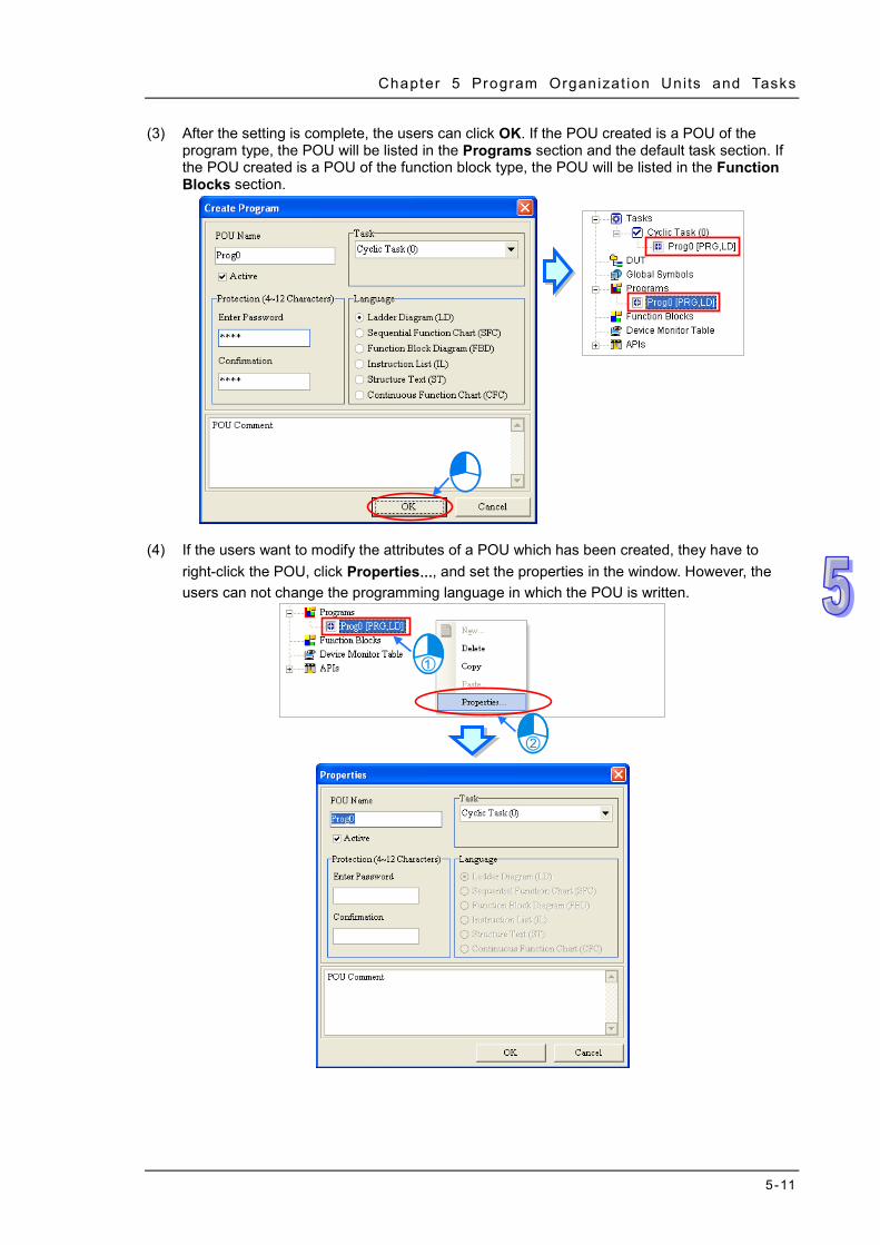
Chapter 5 Program Organizat ion Units and Tasks
5-11
(3) After the setting is complete, the users can click OK. If the POU created is a POU of the program type, the POU will be listed in the Programs section and the default task section. If the POU created is a POU of the function block type, the POU will be listed in the Function Blocks section.
(4) If the users want to modify the attributes of a POU which has been created, they have to
right-click the POU, click Properties…, and set the properties in the window. However, the users can not change the programming language in which the POU is written.

ISPSoft User Manual
5-12
5.4.2 Enabling a POU
ISPSoft provides the function of disabling a POU temporarily. If a POU is disabled, it is skipped when the program is compiled, and the program in the POU is not executed. However, only POUs of the program type can be disabled. This function can be applied to the test of a program or the debugging of a program. If users want to skip certain procedure during the test of a program or the debugging of a program, they can disable the POU. After the test of the program or the debugging of the program is complete, they can enable the POU. The equipment shown below is composed of five workstations, and the working practices are divided into five POUs of the program type.
If the assembling of the equipment is complete, but the assembling of the test instrument is not complete, users can disable the POUs corresponding to test A and test B. The two workstations are skipped when the other parts of the equipment are adjusted.
If users want to enable a POU, they can select the Active checkbox in the window. If the Active checkbox is unselected, the POU is disabled. A POU which is disabled is represented by a gray icon.
*1. Users can disable a POU by removing it from the original task section. However, if the users want to execute the
POU later, they have to assign the POU to the original task again, and rearrange the POUs in the task section. As a result, it is more convenient for the users to disable the POU temporarily by unselecting the Active box in the window.
*2. A POU can be enabled not only by selecting the Active box in the window, but also by the task management tool. Please refer to section 5.5.3 for more information.
5.4.3 Deleting and Copying a POU
If users want to delete a POU, they have to right click the POU and click Delete.
Feeding Positioning
Test A
Test B Discharging
Feeding Test A
Test B Positioning
Discharging

Chapter 5 Program Organizat ion Units and Tasks
5-13
The POU can not be recovered after it is deleted. The POU will be deleted from the project after OK is clicked. If the POU deleted is a POU of the program type, they system will also delete it from the task section.
POU Multi-deletions are also supported. Right-click “Programs” or “Function Blocks” to see and select the option “POU Multi-Delete”. And then users will see the POU Multi_Delete window, use the “Select All”, “Inverse Select” and “Deselect All” buttons to select and delete more than 1 POU at the same time.

ISPSoft User Manual
5-14
If users want to copy a POU, they have to right-click the POU and click Copy.
The POU can be copied into the same project or another project. If the POU copied is a POU of the program type, it can not be copied into the Function Blocks section. If the POU copied is POU of the function block type, it can not be copied into the Programs section. If the users want to paste the POU, they have to right-click Programs or Function Blocks and click Paste. Besides, if the POU copied is a POU of the program type, the POU pasted will not be assigned to any task.
*. If a POU is pasted on a position where the same POU name exists, the system will put CopyOf_n at the end of the POU which is pasted. (n in CopyOf_n is a serial number.)
5.4.4 Setting and Unlocking a POU Password
Users can set a password for a POU in ISPSoft. The setting of a password, and the unlocking of the password are described below. (1) When users create a POU, they can set a password for the POU. If users do not set a
password a POU when the POU is created, but want to protect the POU with a password later, they have to right-click the POU in the project management area and click Properties… to open the Properties window.
(2) Type the same passwords in the Enter Password box and the Confirmation box, and then
click OK. English letters, numerical digits, and special marks can be typed in the boxes. Once the POU is protected with the password, the system asks the users to type the password whenever the window for the POU is opened.

Chapter 5 Program Organizat ion Units and Tasks
5-15
(3) If the users want to unlock the password, they have to open the Properties window again, type the password in the Enter Password box, and click OK.
5.4.5 Exporting a POU of the Program Type
ISPSoft supports the function of exporting POUs, and the function of importing POUs. If there is a group of projects in ISPSoft, users can only export POUs in the project which is being edited presently. Users can export POUs in the project which is being edited presently by clicking the Tools menu, clicking Programs and then Export Programs… They can also export POUs in the project which is being edited presently by clicking the Export on the context menu, and clicking Programs….
In the Export Programs window, specify a path in the Drive/Path box, type a file name in the File Name box, and select POUs of the program type which will be exported in the Program section. If the users want to protect the file which will be exported with a password, they have to select the Password Setting checkbox, type the same passwords in the Password box and the

ISPSoft User Manual
5-16
Confirmation box. English letters, numerical digits, and spaces can be typed in the boxes. Finally, click OK.
5.4.6 Importing a POU of the Program Type
Users can only import POUs into the project which is being edited presently. Besides, a POU of the function block type which has been exported can not be imported into the Programs section. Users can import POUs into the project which is being edited presently by clicking the Tools menu, and clicking Programs and then Import Programs…. They can also import POUs into the project which is being edited presently by right-clicking the project in the project management area, pointing to Import on the context menu, and clicking Programs….
Select a file which will be imported, and then click Open. If the file is protected with a password, the users have to type the password in the Password for Decrypting window, and click OK. The POUs which are imported will not be assigned to any tasks. Besides, if the name of a POU which will be imported is the same as the name of a POU in the project, the system will not allow the POU to be imported, but the other POUs will be imported normally.
Select POUs. Type the same passwords.
Specify a path and type a file name.

Chapter 5 Program Organizat ion Units and Tasks
5-17
5.4.7 Exporting a POU of the Function Block Type
ISPSoft supports the function of exporting POUs, and the function of importing POUs. If there is a group of projects in ISPSoft, users can only export POUs in the project which is being edited presently. Users can export function blocks in the project which is being edited presently by clicking the File menu, pointing to Project, and clicking Export and then Function Blocks…. They can also export function blocks in the project which is being edited presently by right-clicking the project in the project management area, pointing to Export on the context menu, and clicking Function Blocks….
In the Export Function blocks window, specify a path in the Drive/Path box, type a file name in the File Name box, and select POUs of the function block type which will be exported in the Function Blocks section. If the users want to protect the file which will be exported with a password, they have to select the Password Setting checkbox, type the same passwords in the Password box and the Confirmation box. English letters, numerical digits, and spaces can be typed in the boxes. Finally, click OK.

ISPSoft User Manual
5-18
5.4.8 Importing a POU of the Function Block Type
Users can only import POUs into the project which is being edited presently. Besides, a POU of the program type which has been exported can not be imported into the Function Blocks section. Users can import POUs into the project which is being edited presently by clicking the File menu, clicking Function Blocks and then Import Function Blocks, and…. They can also import POUs into the project which is being edited presently by right-clicking the project in the project management area, pointing to Import on the context menu, and clicking Function Blocks….
Select a file which will be imported, and then click Open. If the file is protected with a password, the users have to type the password in the Password for Decrypting window, and click OK. Besides, if the name of a POU which will be imported is the same as the name of a POU in the project, the system will not allow the POU to be imported, but the other POUs will be imported normally.
Select POUs. Type the same passwords.
Specify a path and type a file name.

Chapter 5 Program Organizat ion Units and Tasks
5-19
5.5 Managing Tasks The steps of managing the tasks in ISPSoft are shown below. Please refer to the following sections for more information about the management of the tasks in ISPSoft.
Before managing the tasks in ISPSoft, users have to start the task management tool. There are three ways to start the tasks management tool. Method 1
Right-click Tasks in the project management area, and then click Task Property on the context menu to open the Task Manager window.
Method 2
Unfold the Tasks section in the project management area, and then double-click a task which will be set to open the Task Manager window.
Setting a task property Assigning POUs to the task Arranging the POUs

ISPSoft User Manual
5-20
Method 3
Right-click a POU which will be assigned to a task in the Programs section in the project management area, and then click Task Property on the context menu to open the Task Manager window.
The Task Manager window is shown below.

Chapter 5 Program Organizat ion Units and Tasks
5-21
Task type: The tasks available are listed here.
Task description: The description of a task selected is displayed here.
Task management area: Users can assign POUs to tasks, and arrange POUs.
5.5.1 Setting the Property of a Task and the Condition of an
Interrupt After a task in the Task Type section is selected, the description of the task will be displayed in the Task Description section. Users can set the condition of executing the task in the Task Description section. Besides, the tasks provided by a project for a PLC depend on the functions of the PLC selected, and different tasks have different properties.
The setting of the properties of tasks can be illustrated with some simple examples. Users can refer to the examples below and the operation manual for a PLC for more information about setting the properties of tasks. Example 1: If users want to set the property of an interrupt task for a DVP-SV series PLC, they have
to make sure of the interrupts provided by the DVP-SV series PLC. The interrupts provided by a DVP-SV series PLC are listed in the table below. (The table is in DVP-PLC Application Manual─Programming.)
The Task Type section for a DVP-SV series PLC is shown below. If users want to set a task corresponding to the interrupt I001, they have to select External Interruption (X0) in the Task Type section first. (I001 is triggered when the signal passing through X0 goes from low to high.) The description of External Interruption (X0) will be displayed in the Task Description section. According to the message in the Task Description section, I001 is rising edge-triggered if the value in the External box is 1. As a result, the users have to select 1 in the External box.

ISPSoft User Manual
5-22
Example 2: The figure below is the Task Manager window for AHCPU530-EN. The task selected is
Cyclic (1). Owing to the fact that users can enable and disable a cyclic task in an AH500 series CPU module through the applied instructions TKON and TKOFF, they can set the initial state of the cyclic task. If the Active checkbox is unselected, Cyclic (1) is disabled when the program is executed. Cyclic (1) is not enabled until a POU assigned to another task uses the instruction TKON to enable Cyclic (1). Please refer to AH500 Programming Manual for more information about TKON and TKOFF.
Example 3: The figure below is the Task Manager window for AHCPU530-EN. The task selected is
I/O Interruption (2). Owning to the fact that users can set the condition of an I/O interrupt by themselves, the message in the Task Description section indicates that the condition of I/O Interruption (2) can be set in HWCONFIG. The setting of the condition of I/O Interruption (2) in HWCONFIG is described below.
Suppose I/O Interruption (2) will be triggered after channel 1 on AH02HC-5A receives a certain number of pulses. The setting of I/O Interruption (2) in HWCONFIG is described below. Users can refer to chapter 3 for more information about setting the parameters in a module, and refer to AH500 Operation Manual for more information about the interrupts in an AH500 series CPU module. (1) Double-click HWCONFIG in the project management area in ISPSOft.
(2) Double-click AH02HC-5A to open the Parameter Setting window.
(3) Select CH1~2 Number of Interrupt Setting, and type 2 in the Initial cell for CH1 Number of Interrupt Setting for Comparison.

Chapter 5 Program Organizat ion Units and Tasks
5-23
*. If the value in the Initial cell for CH1 Number of Interrupt Setting for Comparison is the same as the value in the
Initial cell for CH2 Number of Interrupt Setting for Comparison, the same I/O interrupt will be triggered after channel 1 or channel 2 receives a certain number of pulses.
(4) Select CH1~2 Comparison Value Setting, and type 1000 in the Initial cell for CH1
Comparison Value Setting.
(5) Be sure to save the file after the setting is complete. The parameters set in HWCONFIG must
be downloaded to the CPU module so that they can take effect.
5.5.2 Assigning a POU to a Task
After the setting of the property of a task is complete, users can assign POUs to the task. POUs which are sequential function charts can only be assigned to cyclic tasks, and can not be assigned to interrupt tasks. (1) After a task in the Task Type section is selected, the assignment of the POUs will be displayed
in the task management area. The POUs which have not been assigned to the task are in the Unassigned POUs section, and the POUs which have been assigned to the task are in the Assigned POUs section.

ISPSoft User Manual
5-24
(2) If users want to assign a POU in the Unassigned POUs section to the task, the can select the
POU in the Unassigned POUs section, and click .
(3) If the users want to remove a POU from the Assigned POUs section, they can select the POU
in the Assigned POUs section, and click .
5.5.3 Arranging the POUs
After the assignment of POUs to a task is complete, users can arrange the POUs. The order in which the POUs are listed in the Assigned POUs section is the order in which the POUs are executed. (1) If users want to execute a POU in the Assigned POUs section earlier, they can select the
POU in the Assigned POUs section, and click to move the POU upward.
(2) If users want to execute a POU in the Assigned POUs section later, they can select the POU
in the Assigned POUs section, and click to move the POU downward.

Chapter 5 Program Organizat ion Units and Tasks
5-25
(3) After a POU in the Assigned POUs section is selected, users can select the Active checkbox if they want to enable the POU, or unselect the Active checkbox if they want to disable the POU. A POU which is disabled is represented by a gray icon in the project management area.
*.Please refer to section 5.4.2 for more information about enabling a POU.
(4) Click OK in the Task Manager window after the setting of the task is complete.
5.6 Example
5.6.1 Writing a Program by Means of IEC 61131-3
The program created in chapter 4 will be rewritten by means of IEC 61131-3. The program created in chapter 4 is shown below. It will be divided into three parts according to the functions listed below.

ISPSoft User Manual
5-26
This part of the program functions to start or stop the system.
This part of the program functions to inject the glue.
This part of the program functions to count the parts which are conveyed. This section aims at the architecture of a program. The contents related to configuring hardware, setting parameters, testing a program, and debugging a program are the same as the contents of chapter 4. Users can try to complete the related setting by themselves. First, create a new project. Then, refer to chapter 4, and complete the hardware configuration. Finally, refer to section 5.4.1, and create three POUs in the Programs section in accordance with the three points listed above. These three POUs are assigned to Cyclic (0).
Please refer to chapter 4, and write the programs in the POUs shown below. The program in RUN_STOP functions to start or stop the system.

Chapter 5 Program Organizat ion Units and Tasks
5-27
The program in GLUING functions to inject the glue.
The program in COUNTING functions to count the parts which are conveyed.
After the creation of the programs is complete, users have to make sure that the order in which the POUs in the Tasks section are arranged is the same as the order shown below. If the order in which the POUs in the Tasks section are arranged is different from the order shown below, the users have to rearrange the POUs.

ISPSoft User Manual
5-28
If the users want to rearrange the POUs, they have to right-click Tasks in the project management area, and click Task Property on the context menu to open the Task Manager window. Please refer to section 5.5, and rearrange the POUs.
If the creation of the POUs is complete, the result of executing the program will be the same as the result of executing the ladder diagram in chapter 4. Please refer to chapter 4, and compile the program. The program can be tested after it is downloaded to the CPU module.

Chapter 5 Program Organizat ion Units and Tasks
5-29
5.6.2 Example of an Interrupt Subroutine in a DVP Series PLC
Example If the ON button is pressed (X0 is turned ON), Y0~Y7 will scanned in order. If the OFF button is pressed (X1 is turned ON), the output will stop, and the present output state will be retained. If the RST button is pressed (X2 is turned ON), the output will be reset, and Y0~Y7 will be scanned again.
Planning a program
The model used in this example is a DVP-SV PLC, and four POUs are created. The functions of the POUs are described below.
POU name Function
Run_Stop
1. Reset the operation flag M0, transfer the value 1 to the output data register D0, and enable the interrupt.
2. When X0 is turned from OFF to ON, the operation flag M0 is set to ON. 3. When X1 is turned from OFF to ON, the operation flag M0 is set to OFF.
LED The states of Y0~Y7 are updated according to the value in the output data register D0.
Shift The values of the bits in the output data register D0 is shifted by one bit to the left every 0.5 seconds. If the value in D0 is larger than 128, the value 1 will be transferred to D0.
Reset
Transfer the value 1 to the output data register D0, that is, set bit 0 in D0 to ON. The POU will be executed after the external interrupt I201 is triggered. (I201 is triggered when the signal passing through X2 goes from low to high.)
*. Please refer to DVP-PLC Application Manual─Programming for more information about the interrupts in a DVP-SV series PLC and the related applied instructions.
Creating the program
Please create a project for a DVP-SV series PLC.
This section aims at the architecture of a program. The parts related to system setting and communication setting are skipped. Users can refer to the related sections, and complete the related setting by themselves. Please refer to section 3.1 for more information about system setting, and section 2.4 for more information about communication setting.

ISPSoft User Manual
5-30
Create the four POUs in the Programs section in the project management area shown below. When these POU are created, they are assigned to Cyclic.
Write the programs in the POUs shown below.
*. The applied instruction MOV is in the Transmission Comparison section, and the applied instruction EI is in the Loop Control section.

Chapter 5 Program Organizat ion Units and Tasks
5-31
*. The applied instruction MOV is in the Transmission Comparison section.
*. The applied instruction TMR is in the Basic Instructions section, the applied instruction ROL is in the Rotation and Displacement section, the applied instruction MOV is in the Transmission Comparison section, and the comparison contacts are in the Contact Type Logic Operation section.
*. The applied instruction MOV is in the Transmission Comparison section.

ISPSoft User Manual
5-32
Open the Task Manager window after the writing of the program is complete. Owing to the fact that the four POUs are assigned to Cyclic when they are created, the four POUs are in the Assigned POUs section for Cyclic.
Owing to the fact that Reset will be executed after an external interrupt is triggered, Reset is removed from the Assigned POUs section for Cyclic.

Chapter 5 Program Organizat ion Units and Tasks
5-33
After the assignment of the POUs to Cyclic is complete, users can arrange the POUs in the Assigned POUs section. Owing to the fact that Run_Stop and Shift must be executed earlier than LED, the order in which Run_Stop, Shift, and LED are listed in the Assigned POUs section is Run_StopShiftLED.
Select External Interruption (X2) in the Task Type section, and select 1 in the External box in the Task Description section. External Interruption (X2) is triggered when the signal passing through X2 goes from low to high.
Assign Reset to External Interruption (X2). Owing to the fact that there is only one POU in the Assigned POUs section, the users do not need to arrange the POU.
After OK is clicked, the assignment and the setting in the Task Manager window will be applied. The assignment is shown below. The writing of the program has been completed so far. The users can try to compile the program, download the program to the PLC, and test the program by themselves.

ISPSoft User Manual
5-34
Additional remark After the program above is compiled successfully and downloaded to the PLC, the users can upload the program in the PLC to WPLSoft. The program uploaded to WPSoft is shown below. The main program is composed of the three POUs which are assigned to the cyclic task. The order in which the the POUs are executed is Run_StopShiftLED. The contents of the interrupt subroutine I201 are the same as the contents of the POU Reset.
The users can remove Run_Stop from the Tasks section, and disable Shift. After the program is compiled and downloaded to the PLC, the users can upload the program in the PLC to WPLSoft. The main program will not include the two POUs Run_Stop and Shift.
*. WPLSoft is programming software for Delta PLCs. The programming architecture adopted by WPLSoft is
traditional programming architecture. Please refer to WPLSoft User Manual for more information.

Chapter 5 Program Organizat ion Units and Tasks
5-35
5.6.3 Example of an Interrupt Subroutine in an AH500 Series CPU Module
Example If the START button is pressed (X0.0 is turned ON), the system will begin to count. The STOP button must be pressed (X0.1 must be turned ON) within 30 seconds. Otherwise, the alarm will ring (Y0.0 will be turned ON).
Hardware configuration
In this example, the CPU module AHCPU530-EN, the digital I/O module AH16AP11R-5A, and the four-slot main backplane AHBP04M1-5A are used. (The hardware configuration here is the same as the hardware configuration in chapter 4.)
Planning a program In this example, a timed interrupt is triggered every 25 milliseconds, and time intervals are measured through a program. In the figure below, Timed Interruption (0) is triggered every 25 milliseconds, and the value in the 32-bit register (D1, D0) increases by one whenever Timed Interruption (0) is triggered. As long as the PLC keeps running, Timed Interruption (0) is triggered every 25 milliseconds, and the value in the 32-bit register (D1, D0) increases by one whenever Timed Interruption (0) is triggered. Users can calculate the time for which the PLC has run by reading the value in (D1, D0). For example, if the value in (D1, D0) is 10, the time for which the PLC has run is 250 milliseconds (10x25 ms). After the START button is pressed, the present value in (D1, D0) will be transferred to (D3, D2), and the value in (D1, D0) will increase. After the present value in (D1, D0) is transferred to (D3, D2), the value in (D3, D2) will remain unchanged. Users can calculate the time which has elapsed since the START button was pressed by subtracting the value in (D3, D2) from the value in (D1, D0). The value gotten is stored in (D5, D4).
A timed interrupt in an AH500 CPU module is illustrated with the example in this section. The instructions TKON and TKOFF are also illustrated with the example in this section. Five POUs are created. The functions of the POUs are described below.
POU name Function
INT_Timer The value in the 32-bit register (D1, D0) increases by one every 25 milliseconds. (The POU is assigned to Timed Interruption (0).)
Initialize
Reset the flags M0 and M1, transfer the value 0 to the 32-bit registers (D1, D0), (D3, D2), (D5, D4), and (D7, D6), and enable the interrupt. During the first scan cycle, Cyclic (0) to which the POUs are assigned is enabled, and Cyclic (1) to which Initialize is assigned is disabled. As a result, Initialize is only executed during the first cycle.
Time when the START button is pressed Time for which the PLC has run Time having elapsed since the START button was pressed

ISPSoft User Manual
5-36
POU name Function
Control When X0.0 is turned form OFF to ON, the operation flag M0 is set to ON, and the value in (D1, D0) is transferred to (D3, D2). When X0.1 is turned from OFF to ON, or when an overflow occurs, the operation flag M0 is reset.
Time_CHK
Users can calculate the time which has elapsed since the START button was pressed by subtracting the value in (D3, D2) from the value in (D1, D0). The value gotten is stored in (D5, D4). If the value gotten is less than 0, the overflow flag M1 is set to ON.
Signal If the time which has elapsed is more than 30 seconds (25 ms x1200), or the overflow flag M1 is ON, the alarm Y0.0 will be set to ON.
*. Please refer to AH500 Operation Manual and AH500 Programming Manual for more information about the interrupts in an AH500 series CPU module and the related applied instructions.
Creating the program
Please create a project for AHCPU530-EN.
The hardware configuration here is the same as the hardware configuration in chapter 4. Please refer to section 4.4, and complete the hardware configuration and the parameter setting.
Create the five POUs in the Programs section in the project management area shown below. When these POU are created, they are assigned to Cyclic (0).

Chapter 5 Program Organizat ion Units and Tasks
5-37
Write the programs in the POUs shown below.
*. The applied instruction EI is in the Loop Control section, the applied instruction DNMOV is in the Data Transfer section, and the applied instructions TKON and TKOFF are in the Task Control section.
*. The applied instruction EI is in the Four Arithmetic Operations section.

ISPSoft User Manual
5-38
*. The applied instruction D- is in the Four Arithmetic Operations section, and the comparison contact D< is in the Contact Type Logic Operation section.
*. The comparison contact D> is in the Contact Type Logic Operation section.

Chapter 5 Program Organizat ion Units and Tasks
5-39
*. The applied instruction DMOV is in the Data Transfer section.
Open the Task Manager window after the writing of the program is complete. Owing to the fact that the five POUs are assigned to Cyclic (0) when they are created, the five POUs are in the Assigned POUs section for Cyclic (0).
Set the property of Cyclic (0) first. Owing to the fact that Cyclic (0) is enabled by Initialize, the Active checkbox is unselected.
INT_Timer must be assigned to Timed Interruption (0), and Initialize must be assigned to Cyclic (1). As a result, INT_Timer and Initialize are removed from the Assigned POUs section for Cyclic (0).
After the assignment of the POUs to Cyclic (0) is complete, users can arrange the POUs in the Assigned POUs section. Owing to the fact that Control and Time_CHK must be executed earlier than Signal, the order in which Control, Time_CHK, and Signal are listed in the Assigned POUs section is ControlTime_CHKSignal.

ISPSoft User Manual
5-40
Select Cyclic (1) in the Task Type section. Owing to the fact that Cyclic (1) will be disabled after the first scan cycle is complete, the Active checkbox is selected.
Assign Initialize to Cyclic (1). Owing to the fact that there is only one POU in the Assigned POUs section, the users do not need to arrange the POU.
Select Timed Interruption 0 (252) in the Task Type section. The message in the Task Description section indicates that the condition of Timed Interruption 0 (252) can be set in HWCONFIG. The users have to assign a POU to this task, and set the property of this task.
Assign INT_Timer to Timed Interruption 0 (252).
After OK is clicked, the assignment and the setting in the Task Manager window will be applied. The assignment is shown below.

Chapter 5 Program Organizat ion Units and Tasks
5-41
In order to set the property of Timed Interruption 0 (252), HWCONFIG is started.
After HWCONFIG is started, the users can double-click the CPU module to open the PLC Parameter Setting window. Click the CPU tab at the top of the window, and the System tab at the bottom of the window.
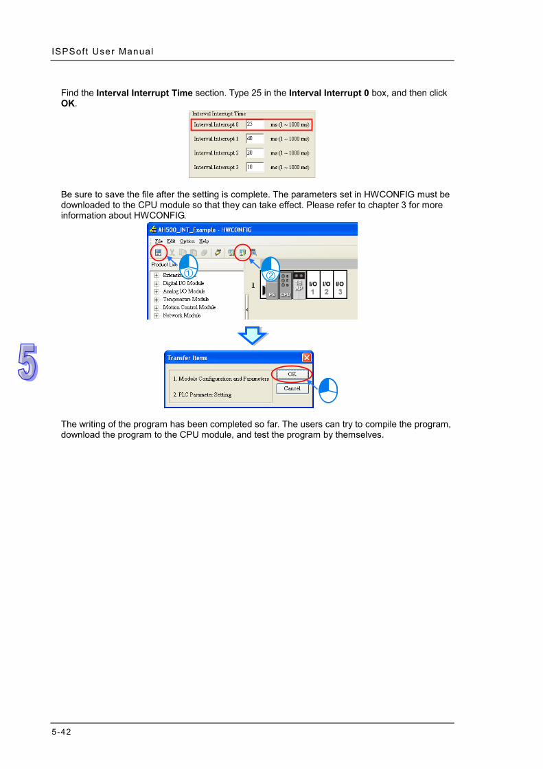
ISPSoft User Manual
5-42
Find the Interval Interrupt Time section. Type 25 in the Interval Interrupt 0 box, and then click OK.
Be sure to save the file after the setting is complete. The parameters set in HWCONFIG must be downloaded to the CPU module so that they can take effect. Please refer to chapter 3 for more information about HWCONFIG.
The writing of the program has been completed so far. The users can try to compile the program, download the program to the CPU module, and test the program by themselves.
6-1
Chapter 6 Symbols Table of Contents 6.1 Introduction of Symbols ............................................................................ 6-2
6.1.1 Application of Symbols and Creation of Identifiers ............................ 6-2 6.1.2 Symbol Classes................................................................................. 6-3 6.1.3 Data Types ........................................................................................ 6-3 6.1.4 Assigning a Device to a Symbol and Setting the Initial Value of a
Symbol……………………………………………………………………...6-5 6.1.5 Modifying a Symbol with an Index Register ....................................... 6-6 6.1.6 Bit in a Device Represented by a Symbol (Only for AH/AS Series CPU
Modules) ........................................................................................... 6-7 6.2 Managing the Symbols in ISPSoft ............................................................ 6-9
6.2.1 Symbol Tables................................................................................... 6-9 6.2.2 Adding a Symbol ..............................................................................6-10 6.2.3 Using a Symbol Whose Data Type is ARRAY or STRING ................6-14 6.2.4 Modifying a Symbol and Editing a Symbol Table .............................6-16 6.2.5 Clearing the Device Addresses Assigned to the Symbols .................6-17 6.2.6 Downloading the Initial Values of the Symbols .................................6-18 6.2.7 Exporting a Symbol Table ................................................................6-19 6.2.8 Importing a Symbol Table ................................................................6-20 6.2.9 Arranging the symbols ......................................................................6-23 6.2.10 Filtering the Symbols ........................................................................6-24 6.2.11 Setting a Range of Devices (Only for DVP Series PLCs) .................6-25
6.3 Example ..................................................................................................6-26 6.3.1 Planning a Symbol Table .................................................................6-26 6.3.2 Writing a Program ............................................................................6-27

ISPSoft User Manual
6-2
6.1 Introduction of Symbols During the process of developing a traditional program for a PLC, it generally takes much time to manage device addresses. Besides, managing or debugging the program in a big project is a burden on users. As a result, the concept of symbols in a high-level programming language is introduced into IEC 61131-3. A device in a PLC can be represented by a symbol, and a device can be automatically assigned to a symbol. The time of assigning devices is saved, a program is more readable, and the efficiency of developing a program increases. *. Variables in ISPSoft are called symbols. As a result, variables are the same as symbols in terms of meaning in this
manual.
6.1.1 Application of Symbols and Creation of Identifiers
A symbol has to be declared before it is used, as shown below. There are two types of symbols. They are global symbols and local symbols. The global symbols can be used in all the POUs in a project, and the local symbols can only be used in the POU in which the local symbols are declared. Besides, the identifier of a local symbol in a POU can be the same as the identifier of a local symbol in another POU. However, if the identifier of a local symbol declared is the same as the identifier of a global symbol, the system will automatically regard the local symbol declared in a POU as a local symbol. The regulations of creating the identifier of a symbol are as follows. An identifier is composed of 30 characters at most, and a Chinese character occupies two
characters. The identifier of a symbol cannot be a name reserved by the system, e.g. an instruction code, a
device name, or a name given a special significance. However, if a name reserved by the system is a part of the identifier of a symbol, the identifier is a legal name. For example, “M0” is an illegal name, but “_M0” is a legal name.
The name of a symbol and the name of an enumeration cannot be the same. Refer to chapter 8 for the enumeration usage.
Spaces cannot be used. For example, “INPUT CH0” is an illegal name. Underlines can be used, but they cannot be used continuously or put at the end of an identifier.
For example, “INPUT_CH0” is a legal identifier, but “INPUT__CH0” and “INPUT_CH0_” are illegal identifiers.
Special marks cannot be used. For example, *, #, ?, \, %, @, and etc. cannot be used.
* When naming for the variable symbols, do not use digits or DFB_(initials of the function keys from the system). To achieve optimization, it is recommended to use what the system assigns for the variable address.

Chapter 6 Symbols
6-3
6.1.2 Symbol Classes In terms of functions, symbols can be classified into five classes. The characteristics of these five classes are described below. VAR-General symbol
The symbols of this class are for general operations only. The significance of a symbol of this class depends on the data type of the symbol or the corresponding device.
VAR_RETAIN - Latched symbol Only AH/AS series modules support the symbols of this class. Users cannot declare the symbols of this class in a function block. The function of the symbols of the VAR_RETAIN class is the same as the function of the symbols of the VAR class. The difference between the symbols of the VAR_RETAIN class and the symbols of the VAR class lies in the fact that the devices automatically assigned to the symbols of the VAR_RETAIN class are latched devices. As a result, the values of the symbols of this class will be retained after the PLC is disconnected. *. Users cannot assign a device to a symbol of this class. Besides, the data type cannot be TIMER, COUNTER, or
STEP.
VAR_INPUT-Symbol used as an input pin of a function block A symbol of this class is used as an input pin of a function block, and is declared in the function block. If a function block is called, the symbol of this class can receive the input value from the caller. Besides, in a ladder diagram/function block diagram, the symbols of this class are put at the left sides of the function blocks, and the pins which receive the values from the caller are assigned to the symbols of this class.
VAR_OUTPUT-Symbol used as an output pin of a function block A symbol of this class is used as an output pin of a function block, and is declared in the function block. After the execution of a function block is complete, the operation result will be sent to the caller through the symbol of this class. Besides, in a ladder diagram/function block diagram, the symbols of this class are put at the right sides of the function blocks, and the pins which sent the operation results to the caller are assigned to the symbols of this class.
VAR_IN_OUT-Symbol used as a feedback pin of a function block A symbol of this class is used as a feedback pin of a function block, and is declared in the function block. Please refer to the following example. When the function block is called, the caller sends the value in D1 to DT_IO, which is a symbol of the VAR_IN_OUT class. After the operation comes to an end, the final value of DT_IO is sent to D1. Besides, in a ladder diagram/function block diagram, the symbols of this class are put at the right sides of the function blocks, and the blue pins which connect to the caller are assigned to the symbols of this class.
6.1.3 Data Types The data type of a symbol determines the significance of the value of symbol. Suppose there are two symbols VAR_1 and VAR_2. The data type of VAR_1 is BOOL, and the data type of VAR_2 is WORD. When VAR_1 and VAR_2 are used in a program, VAR_1 represents a contact, and VAR_1 represents a 16-bit device which can be involved in arithmetic or data transfer.

ISPSoft User Manual
6-4
The data types supported by ISPSoft are listed below. Different models support different data types, and the symbols which can be declared in a POU of the program type are different from the symbols which can be declared in a POU of the function block type.
Data type Description AH/AS DVP
Program FB Program FB
BOOL Boolean data type A Boolean value represents a state of a contact
WORD 16-bit value 16-bit data can be stored.
DWORD 32-bit value 32-bit data can be stored.
LWORD 64-bit value 64-bit data can be stored.
INT 16-bit signed integer The highest bit represents a positive/negative sign.
DINT 32-bit signed integer The highest bit represents a positive/negative sign.
LINT 64-bit signed integer The highest bit represents a positive/negative sign.
REAL 32-bit floating-point value A decimal is represented by a 32-bit value.
LREAL 64-bit floating-point value A decimal is represented by a 64-bit value.
ARRAY
Array data type When a symbol is declared, the size of the array and the array type which will be stored are specified. (An array is composed of 2048 elements at most.)
STRING
String data type An ASCII code is represented by an 8-bit value. When a symbol is declared, the length of the string is specified. (A string is composed of 128 ASCII codes at most.) (*3)
STEP It is used as a recognition flag for a step. (*1) (*3)
Function Block It represents the name of a function block. (*2)
COUNTER Counter data type It represents a counter. (*3)
TIMER Timer It represents a timer. (*3)
POINTER It is a pointer for a word device. (*4)
T_POINTER It is a pointer for a timer. (*4)
C_POINTER It is a pointer for a counter.
HC_POINTER It is a pointer for a high-speed counter. (*4) *1. Please refer to chapter 12 for more information about steps. *2. A symbol in a function block has a special significance. Please refer to chapter 7 for more information. *3. The data type of a symbol of the VAR_INPUT class, the VAR_OUTPUT class, or the VAR_IN_OUT class cannot be
STRING, STEP, COUNTER, or TIMER.

Chapter 6 Symbols
6-5
*4. Please refer to chapter 7 for more information about pointers.
6.1.4 Assigning a Device to a Symbol and Setting the Initial Value of a Symbol
A device is assigned to a symbol according to the data type of the symbol. Users can set the initial value of a symbol. If a project is downloaded, the initial values of the symbols can be written into the devices assigned to the symbols. The principle of assigning devices to symbols is as follows. Different models have different assignment principles.
Model Assignment principle
AH/AS
Users can assign devices to the global symbols and the local symbols declared in the POUs of the program type. The system can also automatically assign devices to the global symbols and the local symbols declared in the POUs of the program type.
The system automatically assigns devices to the local symbols declared in the function blocks. Users cannot assign devices to the local symbols declared in the function blocks by themselves.
The devices assigned by the system are memories reserved by the CPU module, and are not data registers or auxiliary relays. If the data type of a symbol is STEP, TIMER, or COUNTER, the system will automatically assign a stepping relay, a timer, or a counter to the symbol.
DVP
Users can assign devices to all the global symbols and the local symbols. The system can also automatically assign devices to all the global symbols and the local symbols.
The devices assigned by the system are usable devices. (Users can set a range of devices which can be assigned automatically.)
The relation between the data types and the device types which can be assigned is described below.
Data type
AH/AS DVP Device assigned by
users Device assigned by
the system Device assigned by
users Device assigned
by the system
BOOL Contact M/SM or bit in the device D/L/X/Y Internal memory Contact M/X/Y Contact M
WORD D/L/X/Y/E/SR Internal memory D/E/F D DWORD D/L/X/Y/E/SR Internal memory D/E/F D LWORD D/L/X/Y/E/SR Internal memory D/E/F D
INT D/L/X/Y Internal memory None DINT D/L/X/Y Internal memory None LINT D/L/X/Y Internal memory None REAL D/L/X/Y Internal memory D D LREAL D/L/X/Y Internal memory None
STRING D/L/X/Y Internal memory None STEP S S S S
COUNTER C/HC C C C TIMER T T T T
ARRAY
The devices assigned to a symbol whose data type is ARRAY depend on the array type specified. The array is composed of the devices starting from the device assigned by users or the system, and the number of devices in the array conforms to the size of the array. The devices assigned to a symbol whose data type is ARRAY cannot be SR/SM/E/F devices.
*1. If the device assigned to a symbol is an internal memory in an AH/AS series CPU module, users cannot know the actual device address.
*2. Please refer to section 6.2.3 for more information about ARRAY and STRING.

ISPSoft User Manual
6-6
*3. Please refer to section 6.2.11 for more information about setting a range of devices which can be assigned automatically in a DVP series PLC.
*4. A symbol in a function block has a special significance. Please refer to chapter 7 for more information. *5. For example, X0.0 and Y0.1 are bits in the word devices X and Y. Please refer to appendix B for more information.
6.1.5 Modifying a Symbol with an Index Register In ISPSoft, a symbol can be modified by an index register. The format is Identifier@Index register. An index register can be an E device, an F device, or a symbol to which an E device or an F device is assigned.
The data stored in an index register indicates the offset for an object modified. Take the figure above for example. If the value in the index register E0 is 2, VAR_0@E0 indicates that 2 is added to the device address (D100) assigned to VAR_0, that is, VAR_0@E0 represents D102. When M0 is ON, the value 123 is transferred to the data register D102.
The same rule applies to a symbol whose data type is ARRAY. The format is Identifier[Index]@Index register. The index must be a constant. If the index is a symbol, the symbol whose data type is ARRAY cannot be modified by the index register. In the figure below, Ary is an array composed of five elements, and the start device address is D200. When the system compiles the program, D200~D204 are assigned Ary. If the value in the index register E0 is 2, Ary[0]@E0 indicates that 2 is added to the device address (D200) assigned to Ary[0], that is, Ary[0]@E0 represents D202, the device address assigned to Ary[2]. If the value in the index register E0 is 6, Ary[0]@E0 represents D206. D206 is not within the range of devices assigned to the array, but this usage is legal. Owing to the fact that the data stored in an index register indicates the offset for an object modified, users have to be more careful when they modify a symbol whose data type is ARRAY with an index register. Please refer to section 6.2.3 for more information about the usage of arrays.
An AH500 series CPU module differs from a DVP series PLC in the use of an index register to

Chapter 6 Symbols
6-7
modify an operand. Please refer to the following table. Application Example AH/AS DVP
Modifying an operand in an instruction MOV 100 VWD@E0
Depending on the rules of the instructions
Depending on the rules of the instructions
Modifying a contact or coil LD VBL_0@E0
OUT VBL_1@E1 Supporting the modification
Depending on the models
Modifying a symbol whose data type is ARRAY ARY[0]@E0 Supporting the
modification Supporting the modification
*1. In an AH/AS series CPU module, only the E devices are index registers. In a DVP series PLC, the E devices and the F devices are index registers. Please refer to the operation manual for a model for more information.
*2. An index register cannot be modified by another index register. For example, E0@E1 is not allowed. As a result, before a symbol is modified by an index register, users have to make sure that the device assigned to the symbol is not an E device or an F device.
Additional remark (a) The data stored in an index register indicates the offset for a device modified. If the system
automatically assigns a device to a symbol modified, the use of an index register will cause the program to be executed incorrectly because users do not know which device is assigned to the symbol.
(b) If the addition of the value in an index register to a device address produces a device address which is not within the range, the PLC will operate incorrectly. As a result, users have to be more careful when they modify a symbol with an index register. Take AHCPU530-EN for example. If the value in E0 is larger than 35, the operand D65500@E0 represents a device which is not within the range of data registers, and an error occurs in the CPU module.
(c) If the value in an index register is changed, the device which actually operates differs from the original device. As a result, if the original device is not used in the program, the final value in the original device is retained. Take AHCPU530-EN for example. In the figure below, if the value in E0 is 2. M102 is ON when M0 is ON. If the value in E0 is changed from 2 to 3, the device which actually operates becomes M103. M103 is ON when M0 is ON. Owing to the fact that M102 is not used in the program, M102 remains ON.
6.1.6 Bit in a Device Represented by a Symbol (Only for AH/AS Series CPU Modules)
An AH/AS series CPU module supports the manipulation of the bits in a word device. The format is Word device.Bit number. For example, D0.2 indicates that bit 2 in D0 is manipulated. The same rule applies to the symbols. The format is Identifier.Bit number, e.g. VB.2. The rule also applies to

ISPSoft User Manual
6-8
the symbols whose data type is ARRAY. The format is Identifier[Index].Bit number, e.g. Ary[0].1. The bit number must be a decimal constant. No matter what the data type of a symbol modified is, the bit number must be within the range between 0 and 15. Besides, the bits in a device represented by a symbol whose data type is BOOL, STEP, COUNTER, TIMER, a function block, HC_POINTER, C_POINTER, or T_POINTER cannot be manipulated. In the figure below, the data type of VB is WORD. Suppose the present value of VB is 0. When M0 is ON, the value of bit 2 in the device represented by VB is 1, that is, the value of VB is 4.
In an AH/AS series CPU module, an index register can be used with the manipulation of the bits in a device. If an index register is used with the manipulation of the bits in a device, the mark @ has high priority. Please refer to the following example. The data type of VB is WORD. Example 1: VB.1@E0 (VB represents D100. The value in E0 is 3.) 1@E0 is interpreted first. As a result, VB.1@E0 is equivalent to VB.4. The bit which is actually manipulated is bit 4 in D100. Example 2: [email protected] (VB represents D100. The value in E0 is 3.) VB@E0 is interpreted first. As a result, [email protected] represents D103.1. The bit which is actually manipulated is bit 1 in D103. Example 3: [email protected]@E1 (VB represents D100. The value in E0 is 3, and the value in E1 is 2.) VB@E0 and 1@E1 are interpreted separately. As a result, VB@E0 represents D103, and 1@E1 represents 3. [email protected]@E1 represents D103.3. The bit which is actually manipulated is bit 3 in D103. *1. If a bit in a device is manipulated, the system will faithfully get the state of the bit. Users have to judge whether
the state of the bit is significant by themselves. *2. In the present version of ISPSoft, a bit number must be within the range between 0 and 15. However, in the future
version of ISPSoft, the data length of a symbol will allow the bit number to be within the range between 0 and 31, or between 0 and 63, and a symbol will represent a bit, e.g. VB.VC.

Chapter 6 Symbols
6-9
6.2 Managing the Symbols in ISPSoft
6.2.1 Symbol Tables Global symbol table
Double-click Global Symbols in the project management area to open the Global Symbols window.
The option Global Symbols may have more sub-options for some series. For example the AHxxEMC series has more sub-options, including Main Table, Axis Table, and EtherCAT Table. Please refer to the related chapters for more information on how to use these symbols.
Local symbol table
In ISPSoft, the local symbol table in a POU is at the top of the window for the POU. If users click the button under a local symbol table, the local symbol table will be hidden. After the users click the button again, the local symbol table will be displayed.

ISPSoft User Manual
6-10
6.2.2 Adding a Symbol (1) After users double-click or right-click the blank in a symbol table, they can click Add a Symbol
on the context menu.
(2) After Add a Symbol is clicked, the Add Symbol window will appear. Type an identifier in the
Identifier box. Please refer to section 6.1.1 for more information about the regulations of creating the identifier of a symbol.
*1. The window which appears varies with the model selected, and the symbol table created (the global/local
symbol table). However, the setting does not vary. *2. There is a way to open a declaration window in every programming environment. Please refer to chapter
8~chapter 12 for more information. (3) Select a class in the Class drop-down list box. The items in the Class drop-down list box vary
with the symbol table created (the global/local symbol table). Please refer to section 6.1.2 for more information.
*1. The items in the Class drop-down list box for a global symbol or a local symbol in a POU are VAR and
VAR_RETAIN. However, in a project for a DVP series PLC, VAR_RETAIN is not in the Class drop-down list box for a global symbol or a local symbol in a POU.
*2. The items in the Class drop-down list box for a local symbol in a POU of the function block type are VAR, VAR_INPUT, VAR_OUTPUT, and VAR_IN_OUT.

Chapter 6 Symbols
6-11
(4) Click the button at the right side of the Type… box, set the data type of the symbol in the Type Selection window, and click OK. Please refer to section 6.1.3 for more information about the data types.
The setting of Function Block, Data Unit Type, STRING, and ARRAY are described below. Function Block
Select the Function Block option button in the Type Class section, and then select a function block definition in the Type box. If the data type of a symbol is a function block, a function block instance is declared. Please refer to chapter 7 for more information.
Data Unit Type Select the Data Unit Type option button in the Type Class section, and then select a DUT_enumA in the Type box, indicating the symbol is declared here. Please refer to chapter 8 for more information.

ISPSoft User Manual
6-12
STRING
If the data type of a symbol is STRING, users have to set the size of the string. The size of a string is within the range between 1 character and 128 characters. The size of a string that users set is the maximum number of characters in the string. Users can click or to decrease or increase the digit in the ones place of the setting value, and they can click or to decrease or increase the digit in the tens place of the setting value.
ARRAY
If the data type of a symbol is ARRAY, the Array Type window will appear after OK in the Type Selection window is clicked. Users have to select an array type and set the size of the array in the Array Type window. The size of an array is within the range between 1 element and 2048 elements. Users can click or to decrease or increase the digit in the ones place of the setting value, and they can click or to decrease or increase the digit in the tens place of the setting value.
(5) If the Address box is blank, the system will automatically assign a device address to the
symbol. If users want to specify a device address, they can type the device address in the Address box, or specify the device address in the Refer Device window after they click the button at the right side of the Address box. Please refer to section 6.1.4 for more information.

Chapter 6 Symbols
6-13
*1. If the data type of a symbol is a function block, users cannot assign a device address to the symbol. *2. In a project for an AH/AS series CPU module, users cannot assign device addresses to the local symbols
in the function blocks. *3. In an AH/AS series CPU module, the bits in some devices can be manipulated, e.g. X0.0 and D0.1. If one of
these devices is selected in the Refer Device window, the Bit Number box will appear. (6) If users want to set the initial value of the symbol, they can type the initial value in the Initial
box. If the data type of the symbol is ARRAY, the Array Initial Values window will appear after the Initial box is clicked. In the Array Initial Values window, users can set the initial values of the elements in the array. If the data type of the symbol is BOOL, the initial value is either TRUE (abbreviated to T) or FALSE (abbreviated to F). If users type 1 or 0 in the Initial box, the system will automatically convert it into TRUE or FALSE. If the data type of the symbol is STRING, the number of characters in the Initial box cannot be larger than the maximum number of characters in the string which has been set. The characters cannot be put in double quotes. Otherwise, the double quotes will be regarded as a part of the string. Besides, if the data type of the symbol is a function block, users cannot type an initial value in the Initial box.
(7) If After users click the Comment box, they can type a comment about the symbol in the
drop-down box that appears.

ISPSoft User Manual
6-14
(8) There are three checkboxes in the Add Symbol window. Please refer to the descriptions
below for more information. After users make sure of the setting, they can click OK to add the symbol.
Auto-close Dialog
If users unselected the Auto-close Dialog checkbox, the Add Symbol window will not be closed automatically after OK is clicked. Please refer to section 2.3.1 for more information.
Insert If users select the Insert checkbox, the symbol declared here will appear on the selected symbol in the symbol table. If this option is unchecked, it will be added to the last of the symbol table.
Define Global If users select the Define Global checkbox, the symbol declared here will appear in the global symbol table. However, the Define Global checkbox is not in the Add Symbol window for a global symbol.
6.2.3 Using a Symbol Whose Data Type is ARRAY or STRING Symbol whose data type is ARRAY
If users want to use a symbol whose data type is ARRAY in a program, the expression format is Identifier[Index]. Generally speaking, the index is a decimal constant. If the programming language in a project for an AH/AS series CPU module is a structured text, the index can be a symbol. The minimum index value must be 0, whether the index is a constant or a symbol. The maximum index value cannot be larger than or equal to the number of elements in the array. For example, if the number of elements in an array is 10, the index value must be within the range between 0 and 9. If the index is a symbol, the value of the symbol cannot be larger than the number of elements in the array. Otherwise, an error will occur during the operation.

Chapter 6 Symbols
6-15
If users declare a symbol whose data type is ARRAY, they have to select an array type, and set the size of the array. The number of elements in an array must be within the range between 1 and 2048. A start device address is assigned to a symbol whose data type is ARRAY according to the array type. Please notice that the start device address is assigned to a symbol whose data type is ARRAY cannot be an SR device, an SM device, an E device, or an F device. Please refer to section 6.1.4 for more information. Besides, an array is composed of the devices starting from the device assigned by users or the system, and the number of devices in the array conforms to the size of the array. In the figure below, ARRAY[3] OF DWOED in the Type… cell for Ary_0 indicates that the array is composed of 3 elements, and the array type is DWORD. The device address in the Address cell for Ary_0 indicates that the start device address is D0. As a result, the array is composed of D0~D5 (6 word devices). ARRAY[5] OF BOOL in the Type…cell for Ary_1 indicates that the array is composed of 5 elements, and the array type is BOOL. The device address in the Address cell for Ary_1 indicates that the start device address is M0. As a result, the array is composed of M0~M4.
When users declare a symbol whose data type is ARRAY, they can set the initial value of the symbol. Please refer to the following example. [1,2,3,4,5] in the Initial Value cell for A_Ary indicates that the initial value of A_Ary[0] is 1, the initial value of A_Ary[1] is 2, the initial value of A_Ary[2] is 3, the initial value of A_Ary[3] is 4, and the initial value of A_Ary[4] is 5. [1,3(0),5] in the Initial Value cell for B_Ary indicates that the initial value of B_Ary[0] is 1, the initial value of B_Ary[1] is 0, the initial value of B_Ary[2] is 0, the initial value of B_Ary[3] is 0, and the initial value of B_Ary[4] is 5.
A_Ary B_Ary Element Initial value Element Initial value A_Ary[0] 1 B_Ary[0] 1 A_Ary[1] 2 B_Ary[1] 0 A_Ary[2] 3 B_Ary[2] 0 A_Ary[3] 4 B_Ary[3] 0 A_Ary[4] 5 B_Ary[4] 5
When the element is with a two-dimensional array or three-dimensional array in the data unit type, the symbol can use [n,n] or [n,n,n]. As the image shown below, the element pt1 is with a three-dimensional array, the data unit type of the variable can be vardut.pt1[1,1,1] to assign the element [1,1,1] from the array.

ISPSoft User Manual
6-16
Symbol whose data type is STRING
In ISPSoft, a string is composed of ASCII codes, and the ASCII codes are surrounded by double quotes, e.g. “ABCD”. A symbol whose data type is STRING is generally used with an applied instruction. Please refer to the programming manual for a model for more information. Besides, only AH/AS series CPU modules support the symbols whose data types are STRING, and the data type of a symbol of the VAR_INPUT class, the VAR_OUTPUT class, or the VAR_IN_OUT class in a function block cannot be STRING. As a result, if users want to process a string in a function block, they can create the string as a global symbol. Please refer to chapter 7 for more information about the usage of function blocks. When users declare a symbol whose data type is STRING, they can specify the maximum size of the string. The number of characters in a string is within the range between 1 and 128, and one character occupies 1 byte. The number of devices assigned to the characters in a string must conform to the size of the string, and one extra byte must be assigned to the ending character in the string. If the last character and the ending character in a string does not occupy the two bytes in a word device, the ending character will be assigned another device. For example, two word devices (four bytes) will be assigned to a string which is composed of three characters, and three word devices (six bytes) will be assigned to a string which is composed of four or five characters. Please refer to the following figure. The number in the parentheses in the Type… cell for a symbol whose data type is STRING indicates the maximum size of the string. Besides, the characters in the Initial Value cell for a symbol whose data type is STRING cannot be put in double quotes, and the number of characters in the Initial Value cell for the symbol whose data type is STRING must be less than or equal to the maximum number of characters in the string.
6.2.4 Modifying a Symbol and Editing a Symbol Table
If users want to modify the attributes of a symbol, they can double-click the symbol to open the declaration window, and modify the setting values in the boxes according to the description in section 6.2.2.
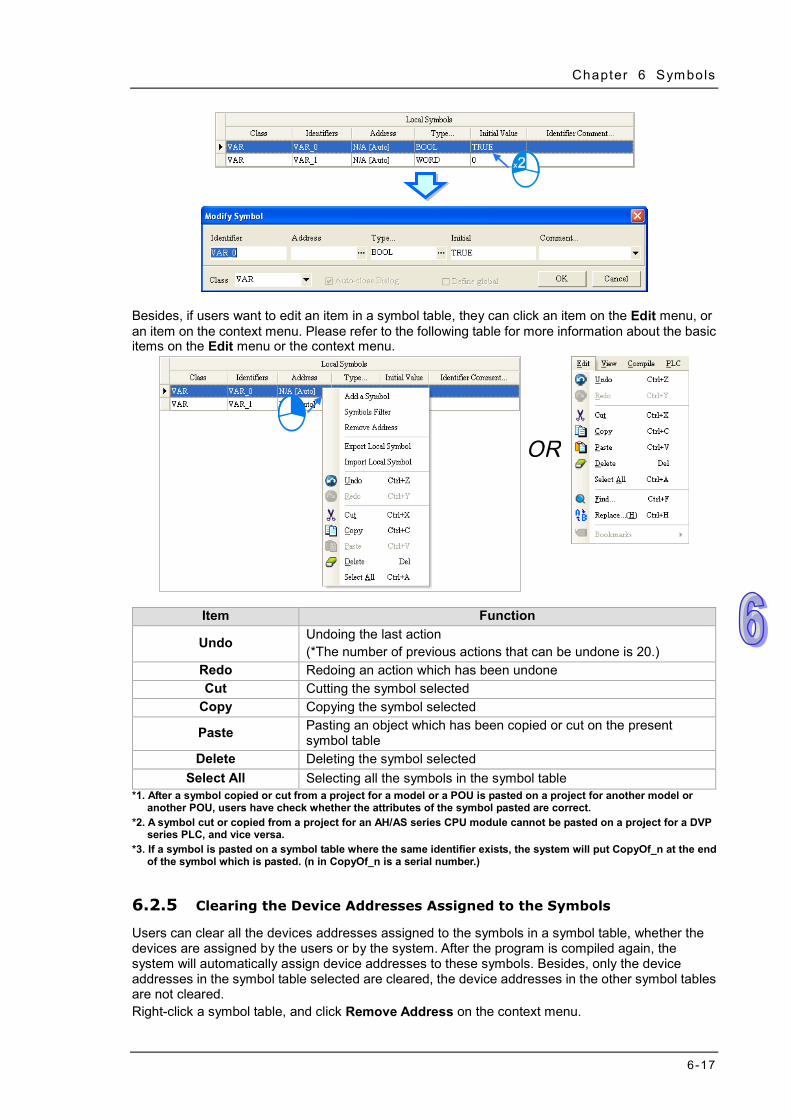
Chapter 6 Symbols
6-17
Besides, if users want to edit an item in a symbol table, they can click an item on the Edit menu, or an item on the context menu. Please refer to the following table for more information about the basic items on the Edit menu or the context menu.
Item Function
Undo Undoing the last action (*The number of previous actions that can be undone is 20.)
Redo Redoing an action which has been undone Cut Cutting the symbol selected
Copy Copying the symbol selected
Paste Pasting an object which has been copied or cut on the present symbol table
Delete Deleting the symbol selected Select All Selecting all the symbols in the symbol table
*1. After a symbol copied or cut from a project for a model or a POU is pasted on a project for another model or another POU, users have check whether the attributes of the symbol pasted are correct.
*2. A symbol cut or copied from a project for an AH/AS series CPU module cannot be pasted on a project for a DVP series PLC, and vice versa.
*3. If a symbol is pasted on a symbol table where the same identifier exists, the system will put CopyOf_n at the end of the symbol which is pasted. (n in CopyOf_n is a serial number.)
6.2.5 Clearing the Device Addresses Assigned to the Symbols Users can clear all the devices addresses assigned to the symbols in a symbol table, whether the devices are assigned by the users or by the system. After the program is compiled again, the system will automatically assign device addresses to these symbols. Besides, only the device addresses in the symbol table selected are cleared, the device addresses in the other symbol tables are not cleared. Right-click a symbol table, and click Remove Address on the context menu.

ISPSoft User Manual
6-18
6.2.6 Downloading the Initial Values of the Symbols
Users can set the initial value of a symbol when they declare the symbol. If a project is downloaded, the initial values of the symbols can be written into the devices assigned to the symbols. However, the initial values of the symbols in a project are written into the devices assigned to the symbol only when the project is downloaded. If a PLC is disconnected or stops running, and runs again, the values of the symbols in the program in the PLC will not be the initial values. In order to ensure that the values of the symbols in the program in a PLC are the initial values whenever the PLC begins to run, it is suggested that users download the initial values of the symbols. Besides, when the online update is executed, the system does not download the initial values of the symbols. Users can click the PLC menu, point to Transfer, and click Download to open the Transfer Setup window. The can also click on the toolbar to open the Transfer Setup window. After the users select the Initial Value checkbox in the Transfer Selections section, and click OK, the initial values will be written into the PLC.

Chapter 6 Symbols
6-19
*. Before the initial values are downloaded, users have to make sure that ISPSoft is connected to the PLC normally. Please refer to section 2.4 for more information about communication setting.
6.2.7 Exporting a Symbol Table The symbols created in a project can be exported as a CSV file. The data which is exported can be edited and managed through Microsoft Excel. If users want to export a symbol table, they can right-click the symbol table, and click Export Global Symbol or Export Local Symbol on the context menu.
The users can also export the global symbol table in a project through the toolbar or the project management area. However, if there is a group of projects in ISPSoft, the users can only export the global symbol table in the project which is being edited presently. After users click the Tools menu, point to Export, and click Global Symbols…, the global symbol table in the project which being edited presently will be exported. The users can also export the global symbol table in the project which is being edited presently by right-clicking the project in the project management area, pointing to Export, and clicking Global Symbols….

ISPSoft User Manual
6-20
6.2.8 Importing a Symbol Table If users want to create symbols, they can add the symbols to a symbol table. If the users want to create a large number of symbols easily, they can export a symbol table as a CSV file, edit the CSV file through Microsoft Excel, and import the new CSV file into ISPSoft.
If users want to import a symbol table, they can right-click a symbol table, and click Import Global Symbol or Import Local Symbol on the context menu.
The users can also import the global symbol table in a project through the toolbar or the project management area. However, if there is a group of projects in ISPSoft, the users can only import the global symbol table in the project which is being edited presently.

Chapter 6 Symbols
6-21
After users click the Tools menu, point to Import, and click Global Symbols…, the global symbol table in the project which being edited presently will be exported. The users can also import the global symbol table in the project which is being edited presently by right-clicking the project in the project management area, pointing to Import, and clicking Global Symbols….
Select a file which will be imported in the Import Symbol List window, select an option button in the Clear Table before Importing section, and click OK.
Additional remark A symbol table exported from a project for a model or a POU can be imported into a project for another model or another POU. However, if a symbol in a file which will be imported is in one of the situations listed below, the symbol will be automatically eliminated or converted. Besides, if an error occurs when a symbol table is imported, the error log will be saved as a file whose primary filename is “Project name_ErrorLog” in a folder in which the project (*.isp) is saved. Users can know the error occurring when the symbol is imported by viewing the file. (a) If a symbol in a file is imported into a symbol table where the same identifier exists, the symbol
will be automatically eliminated from the file. If the contents of a symbol table are cleared before a symbol table is imported, no such problem will occur.
(b) If the data type of a symbol in a file is not supported by a project for a model, the symbol is eliminated from the file when the file is imported into the project.
(c) If the device assigned to a symbol in a file is not supported by a project for a model, or the device is not within the range of devices in the model, the symbol is eliminated from the file when the file is imported into the project.
(d) If the class of a symbol in a file is incompatible with the symbol table in a POU or a global symbol table, the symbol is eliminated from the file when the file is imported into the symbol table in the

ISPSoft User Manual
6-22
POU or the global table. (e) If a symbol in a project for an AH/AS series CPU module is a symbol of the VAR_RETAIN class,
the symbol will become a symbol of the VAR class after the symbol is imported into a project for a DVP series PLC.
An example of importing the global symbol in a project for AHCPU530-EN into a project for a DVP-SV series PLC is shown below. Var_A, Var_B, and Var_C in the project for AHCPU530-EN can be imported into the project for a DVP-SV series PLC. Var_C in the project for AHCPU530-EN is a symbol of the VAR_RETAIN class. After Var_C in the project for AHCPU530-EN is imported into the project for the DVP-SV series PLC, Var_C becomes a symbol of the VAR class. Owing to the fact L0 is not supported by the DVP-SV series PLC, Var_D is eliminated. D65535 is not within the range of devices in the DVP-SV series PLC, and therefore Var_E is eliminated. Var_F is eliminated because the DVP-SV series PLC does not support the symbols whose data types are STRING.
Users not only have to pay attention to the data formats in symbol tables, but also have to pay attention to the comments on the symbols in a symbol table. A CSV file can be opened in Microsoft Excel and Notepad, as shown below. In a CSV file, the cells are divided by the commas. As a result, if there are commas in the Identifier Comment… cell for a symbol in a symbol table, the system will automatically regard the contents after the first comma as the contents of other cells, as shown by C2 and C3 which are in the red circle below. After the symbol table is imported again, the contents after the first comma will be lost.
Before the symbol table is exported After the symbol table is imported

Chapter 6 Symbols
6-23
6.2.9 Arranging the symbols In the local symbol table in a function block, the order in which the symbols of the VAR_INPUT class, the symbols of the VAR_IN_OUT class, and the symbols of the VAR_OUTPUT class are arranged affects the order in which the operands in the function block are arranged. If users want to arrange the symbols in the local symbol table in a function block, they can right-click a symbol which will be moved upward or moved downward, and press Alt+ or Alt+ on the keyboard.
Besides, if users click the heading Identifier or Address in the global symbol table in a project or the local symbol table in a POU of the program type, the data in the table will be sorted according to the contents of the Identifier column or the Address column, and a mark indicating the sort direction will appear in at the right side of the heading Identifier or Address. Owing to the fact that the order in which the symbols in the local symbol table in a function block are arranged affects the order in which the operands in the function block are arranged, the data in the local symbol table in a function block cannot be sorted in this way.

ISPSoft User Manual
6-24
6.2.10 Filtering the Symbols Users can view the symbols which meet the same conditions. (1) Right-click a symbol table, and click Symbols Filter on the context menu.
(2) Users can set the conditions in the Symbols Filter window. The wildcard character “*” can be used to substitute for any character or characters in a string. The symbols which satisfy the conditions set are sieved out. If the users want to ignore a certain condition, they can leave the box for the condition blank. Click OK after the setting is complete.
(3) The symbols which are sieved out are displayed in the additional page. The users can switch
between the pages by clicking the tabs at the top of the table. If several groups of symbols are sieved out, the users can switch among the tabs by clicking or in the upper right corner of the window. If users click in the upper right corner of a page, the page will be closed. Besides, these additional pages are for view only. Users cannot edit the tables in the pages. After the users click the Normal tab, they can edit the original symbol table.

Chapter 6 Symbols
6-25
6.2.11 Setting a Range of Devices (Only for DVP Series PLCs) The devices automatically assigned to the symbols in a project for a DVP series PLC are devices available to users. Users set a range of devices which can be automatically assigned to the symbols in a project so that they can manage the devices conveniently. They can set a range of devices for a project created. When the program in a project is compiled, devices within the range which is set are assigned to the symbols. If the number of symbols is larger than the devices within the range, an error message showing that the devices are insufficient will appear after the program in a project is compiled. Please refer to section 6.1.4 for more information about assigning devices to the symbols in a project. Unfold the PLC section in the project management area in a project for a DVP series PLC, double-click Device Resource Allocation.
Users can set a device range in the Device Resource Allocation window. Every type of device has its limitations. For example, the data registers in a DVP-SV series PLC start from D2000, the auxiliary relays start from M2000, the counters are 16-bit counters, and the timers take 100 milliseconds as the timing unit. If users select a device address which is not allowed, the system will modify it automatically. Click OK after the setting is complete. The setting here will be saved with the project.

ISPSoft User Manual
6-26
6.3 Example An example of creating a ladder diagram is shown in chapter 4. In section 5.6.1, the program created in chapter 4 is rewritten by means of IEC 61131-3. In the following sections, the device names in the program created in section 5.6.1 will be replaced by symbols. 6.3.1 Planning a Symbol Table
The symbols which correspond to the device names in the program created in section 5.6.1 are listed in the following table. Please refer to the descriptions below for more information.
Original device name Identifier Address
specified Declaration
position Function
X0.0 START_BT X0.0 Global symbol table START button X0.1 STOP_BT X0.1 Global symbol table STOP button X0.2 InP_SNR_1 X0.2 Global symbol table In position sensor 1 X0.3 InP_SNR_2 X0.3 Global symbol table In position sensor 2 X0.4 CNT_SNR X0.4 Global symbol table Counting sensor Y0.0 CONVEYER Y0.0 Global symbol table Conveyer
Y0.1 TRIG_1 Y0.1 Global symbol table Trigger signal for injector 1
Y0.2 TRIG_2 Y0.2 Global symbol table Trigger signal for injector 2
M0 RUNNING A device address is assigned automatically.
Global symbol table Operation flag
M1 COMPLETE A device address is assigned automatically.
Global symbol table Completion flag
M2 ERROR A device address is assigned automatically.
Global symbol table Error flag
D0 CNT_DT A device address is assigned automatically.
Local symbol table Number of parts which are conveyed
The X devices and the Y devices in the PLC are contacts connected to the equipment. The X
device addresses and the Y device addresses are related to the wiring of the equipment. Users have to specify the device addresses by themselves. Besides, it is suggested that the X devices and the Y devices should be created in the global symbol table although some X devices and Y devices are only used in a certain POU. After the X devices and the Y device are created in the global symbol table, the subsequent maintenance such as changing the wiring and accessing the contacts in the additional program will be more convenient to users. However, it is not necessary for users to create the X devices and the Y devices in the global symbol table. The users can decide by themselves.
Owing to the fact that M0, M1, and M3 are used in the different POUs, the symbols correspond to the three flags are declared in the global symbol table. Users do not need to assign device addresses to the symbols, and therefore the system assigns device addresses to them.
The number of parts which are conveyed is stored in D0, and D0 is only used in the COUNTING. As a result, the symbol corresponding to D0 is declared in the local symbol table in the COUNTING, and the system assigns a device address to D0.

Chapter 6 Symbols
6-27
6.3.2 Writing a Program
Users can directly modify the program created in section 5.6.1, or write the program shown in section 5.6.1 again. If the users want to write the program again, they have to create a new project, and refer to chapter 4 and section 5.6.1 for more information. First, open the Global Symbols window. Then, refer to section 6.2, and create the symbols shown below in the global symbol table.
Double-click RUN_STOP in the project management area after the creation of the symbols in the global symbol table is complete. If users directly modify the program created in section 5.6.1, they will find that the symbols to which they assign the device addresses replace the corresponding device names, and the comments on the symbols replace the original comments on the devices. Please refer to the contents below if the program displayed in RUN_STOP is not the same as that shown in the figure below.

ISPSoft User Manual
6-28
The users can choose whether to display the symbols to which they assign devices in the ladder diagram. If on the toolbar is pressed, the device names and the comments on the devices will be displayed in the program. If is not pressed, the identifiers and the comments on the symbols will be displayed in the program.
*. M0 is not assigned to any symbol, and therefore it remains unchanged if is not pressed. Likewise, if users do not assign a device address to a symbol, or the system automatically assigns an internal memory to a symbol,
the symbol will remain unchanged after is pressed. The operation flag M0 can be replaced by the identifier RUNNING. The users can refer to chapter 4, and type RUNNING directly. They can also click M0, click in the box, and select an identifier on the drop-down list. Besides, the users can press Page Down on the keyboard when they edit the box. The users can select an identifier on the drop-down list by or on the keyboard. Press Enter on the keyboard after the selection is complete.
Refer to the description above, and write the program in the POU shown below.

Chapter 6 Symbols
6-29
If users want to write the program shown in section 5.6.1 again, they have to refer to chapter 4 and section 5.6.1, and complete the hardware configuration, the parameter setting, and the task management. After the writing of the program is complete, the users have to compile the program, and download the parameters and the program to the CPU module. Before the program is downloaded to the CPU module, the users have to select the Initial Value checkbox in the Transfer Setup window. Once the Initial Value checkbox in the Transfer Setup window is selected, the initial value of CNT_DT in COUNTING will be written into the CPU module.

ISPSoft User Manual
6-30
MEMO

7-1
Chapter 7 Function Block and Library
Table of Contents 7.1 Knowing Function Blocks ......................................................................... 7-2
7.1.1 Introduction of Function Blocks ......................................................... 7-2 7.1.2 Characteristics and Advantages of Function Blocks .......................... 7-3
7.2 Structure of the Function Blocks in ISPSoft .............................................. 7-3 7.2.1 En Pin of a Function Block ................................................................ 7-4 7.2.2 Symbols in a Function Block ............................................................. 7-4 7.2.3 Input/Output Pins of a Function Block ............................................... 7-5 7.2.4 Symbol Whose Data Type is POINTER, T_POINTRER, C_POINTER,
or HC_POINTER ............................................................................... 7-8 7.2.5 Function Block Definition and Function Block Instance .................... 7-11 7.2.6 Calling Relation Between Function Blocks .......................................7-15 7.2.7 Assigning a Memory Block to a Function Block ................................7-16
7.3 Using a Function Block ............................................................................7-21 7.3.1 Basic Specifications for the Function Blocks ....................................7-21 7.3.2 Special Pulse Instructions Used in Function Blocks (Only for AH/AS
Series CPU modules) .......................................................................7-22 7.3.3 Monitoring the Program in a Function Block .....................................7-23 7.3.4 Modifying the Program in a Function Block ......................................7-24
7.4 Example ..................................................................................................7-25 7.4.1 Planning a Program ..........................................................................7-25 7.4.2 Creating the Program .......................................................................7-25
7.5 Knowing the Library .................................................................................7-34 7.5.1 Creating the User-defined Library ....................................................7-34 7.5.2 Including the Function Blocks in the User Defined Library ...............7-36 7.5.3 Using Delta Library ...........................................................................7-38

ISPSoft User Manual
7-2
7.1 Knowing Function Blocks Function blocks (FB) and Function (FC) play important roles in the PLC programming. They are also supported by IEC 61131-3. Owing to the characteristics and advantages of function blocks, ISPSoft also supports and offer many functionalities related to function blocks, for example user-defined FB POU and system-defined FB POU. Though self-defined FC POU is not supported, ISPSoft provides API instructions for users to use as system-defined FC POU.
7.1.1 Introduction of Function Blocks
A function block is a component in a program which performs an operation. It is a type of POU, but it can not operate by itself. After a POU of the program type calls a function block, and sends the related parameters, the function of the function block can be executed. After the execution of the function block is complete, the internal operation result will be sent to the device or symbol specified by the superior POU (caller). A function block is shown below. The appearance of a function block is similar to that of an applied instruction in that there are input pins and output pins. The usage of a function block is also similar to that of an applied instruction. A function block is different from an applied instruction in that users have to declare a symbol whose data type is a function block in the superior POU (caller) which calls the function block. Besides, a function block can call another function block.
A function block is a memory unit. Every function block is assigned a substantial memory block where the values of the internal symbols are stored. Owing to the fact that the value of the symbol in a function block will be retained after the function block is executed, every execution result is affected by the last execution result. In other words, the output values may be different even if the input values are the same. An application example of a function block is shown in the figure below. There is a symbol whose data type is a function block in the local symbol table in the superior POU (caller). The name in the Type… cell is the same as the name of the function block. Please refer to the following sections for more information about the usage of a function block.

Chapter 7 Funct ion Block
7-3
7.1.2 Characteristics and Advantages of Function Blocks Owing to the fact that function blocks present characteristics and advantages that traditional programming of a PLC does not have, function blocks are supported by IEC 61131-3, and are widely used by users. Modular design
A large program is divided into several subroutines, and the subroutines are created as function blocks. The function blocks are arranged and called by POUs of the program type.
Highly independent Different function blocks can be created by means of different programming languages such as a ladder diagram, an instruction list, a structured text, and a function block diagram according to the characteristics of the function blocks or a programmer’s habit. Besides, when a POU calls a function block, the programming language by which the program in the function block is written does not need to be considered. For example, if a complex operation has to be performed in a part of a ladder diagram, users can create the part of the ladder diagram as a function block by means of a structured text, and the function block can be called by the original ladder diagram.
Reusable Once a function block is created, it can be used repeatedly as long as users conform to the rule of using the function block.
Highly portable After a function block is created, it can be used in the original project. Besides, after the function block is exported, it can be imported into another project. As a result, users can gradually create their own function blocks.
Function blocks can be maintained conveniently. The program in a function block is an independent module. If an error occurs in a function block, or the function of a function block does not meet the actual requirement, users can just modify the program in the function block, and do not need to debug or modify the whole program,
The readability of a program is increased. Users can write a complex program or a program which will be used repeatedly in a function block, and the function block can be called by the original program. The structure of the original program becomes more simplified, and the program becomes more readable.
Highly confidential After users set a password for a function block created, they can create their own core technology in the function block without care, and provide the function block for other users. Besides, system suppliers or software developers can provide function blocks which have specific functions for customers.
Highly efficient The application of function blocks provides a highly efficient development environment in terms of project development. Owing to the fact that function block are modular, developers and manufacturers can take part in the development of a project together, and the use of human resources are more flexible.
7.2 Structure of the Function Blocks in ISPSoft Please refer to the following figure. The internal structure of a function block is similar to that of a POU of the program type. It is composed of a local symbol table and a program. A function block is edited in a way in which a POU of the program type is edited. The programming languages that users can make use of to create the function blocks in ISPSoft are ladder diagrams, instruction lists, structured texts, and function block diagrams, but are not sequential function charts. Besides, a function block can call another function block. When a function block is called, the programming language by which program in the function block is written does not need to be considered.

ISPSoft User Manual
7-4
7.2.1 En Pin of a Function Block A superior POU (caller) calls a function block in a way similar to the way in which an applied instruction is executed. Whether a function block is executed depends on the logic state sent to the En pin of the function block. If the logic state sent to the En pin of a function block is ON, the function block will be executed. If the logic state sent to the En pin of a function block is OFF, the function block will not be executed. The Eno pin of a function block functions to send the logic state sent to the En pin of the function block. Besides, if a function block is used in a structured text, the function block does not have an En pin. Please refer to chapter 11 for more information.
7.2.2 Symbols in a Function Block Function blocks are similar to POUs of the program type in that users can create local symbols in the function blocks. Local symbols can also be used in a function block. However, if local symbols are used in a function block in a project, the function block may not portable. If the function block is imported into another project, the project may not have the same global symbols. The symbol classes related to function blocks are described below. Please refer to chapter 6 for more information. Symbol class
Class Description
VAR The symbols of this class are for the operations in function blocks only. After a function block is executed, the value of the symbol in the function block will be retained.
VAR_INPUT
A symbol of this class is used as an input pin of a function block. It receives the value of an operand specified by the superior POU (caller). When the function block is executed, the value of the operand is copied into the function block.

Chapter 7 Funct ion Block
7-5
Class Description
VAR_OUTPUT
A symbol of this class is used as an output pin of a function block. After the execution of a function block is complete, the operation result will be sent to the operand specified by the superior POU (caller) through the symbol of this class.
VAR_IN_OUT
A symbol of this class is used as a feedback pin of a function block. When the function block is called, the value of an operand specified by the superior POU (caller) is sent to the function block through the symbol of this type. After the function is executed, the operation result is sent to the operand specified by the superior POU (caller).
Data types
Model Description
AH/AS BOOL, WORD, DWORD, LWORD, INT, DINT, LINT, REAL, LREAL, ARRAY, STRING, POINTER, T_POINTER, C_POINTER, HC_POINTER, and a function block
DVP BOOL, WORD, DWORD, LWORD, REAL, ARRAY, STEP, TIMER, and COUNTER *1. The data type of a symbol of the VAR_INPUT class, the VAR_OUTPUT class, or the VAR_IN_OUT class can not
be STRING, STEP, COUNTER, or TIMER. *2. Please refer to section 7.2.4 for more information about POINTER, T_POINTER, C_POINTER, and
HC_POINTER.
Assigning memories to the symbols in a function block
Model Description
AH/AS When the symbols whose data type is a function block, and the local symbols created in a function block are declared, users can not assign device addresses to them. The system will automatically assign memories reserved by the CPU module.
DVP Every symbol whose data type is a function block is assigned a P device. Besides, the system automatically assigns devices in the PLC to the local symbols in a function block instance according to the data types of the local symbols.
*. Please refer to sections 7.2.5~7.2.7 for more information about function block instances and the assignment of memories.
7.2.3 Input/Output Pins of a Function Block When a POU calls a function block, it sends the value in a device to the input pin of the function block. After the function block is executed, the operation result is sent to the device in the POU through the output pin of the function block. Please refer to the following figures. Before a function block is executed
The caller assigns D0 to DT_IN, the input pin of the function block. When the function block is called, the system sends the present value in D0 to DT_IN. (DT_IN is a symbol of the VAR_INPUT type.)
After a function block is executed
After the function block is executed, the value of DT_IN becomes 89. The value in D0 is unchanged. Besides, DT_OUT sends the final operation result to D2, the device specified by the

ISPSoft User Manual
7-6
caller. Even if the value in D2 is overwritten during the execution of the program, the value of DT_OUT will remain unchanged. (DT_ OUT is a symbol of the VAR_OUTPUT class.)
Although the value of the symbol of the VAR_IN_OUT class will be sent to the device that the caller assigns to the symbol after the function block is executed, the present value in the device specified by the caller is sent to the symbol before the symbol sends the final operation result to the device.
*. The data type of the symbol of the VAR_IN_OUT class in a function block in a project for an AH/AS series PUC module can be POINTER. The caller can send the device address to the function block through the symbol whose data type is POINTER. Please refer to the following section for more information.
Please refer to the function blocks below. FB_Var is the pin of the function block, and P_Var is the operand that the superior POU (caller) assigns to FB_Var. The data type of P_Var and that of FB_Var must conform to the basic principle described below. However, in order to make the writing of a program more convenient, ISPSoft provides some special principles. As long as the data type of P_Var and that of FB_Var conform to one of the special principles, the system will regard the data types as legal data types even if the data types does not conform to the basic principle.
Basic principle for the general data types
The data type of P_Var must be the same as the data type of FB_Var. Special principles for the general data types (Please refer to the following table.)
1. If either the data type of P_Var or the data type of FB_Var is WORD, DWORD, or LWORD, the data type of the other symbol can be WORD, DWORD, LWORD, INT, DINT, LINT, REAL, or LREAL. If this condition is met, the data length of P_Var can be larger than or equal to the data length of FB_VAR.
2. If the data type of P_Var is STEP, the data type of FB_Var can be BOOL. The state of the step in the caller will be used in the function block.
Data type FB_Var (function block)
WORD DWORD LWORD INT DINT LINT REAL LREAL BOOL
P_VAR (caller)
WORD
DWORD LWORD
INT

Chapter 7 Funct ion Block
7-7
Data type FB_Var (function block)
WORD DWORD LWORD INT DINT LINT REAL LREAL BOOL DINT LINT
P_VAR (caller)
REAL LREAL BOOL STEP
In addition to the principles for the general data types described above, there are principles for the symbols whose data type is ARRAY. Basic principles for the symbols whose data types are ARRAY
1. The array type of P_Var must be the same as the array type of FB_Var. 2. If the array type of P_Var is the same as the array type of FB_Var, the size of the array for
P_Var can be larger than the size of the array for FB_VAR. Special principles for the symbols whose data types are ARRAY
1. When the array types are compared, the first special principle for the general data types applies.
2. If either the data type of P_Var or the data type of FB_Var is ARRAY, the system will regard the other symbol whose data type is not AARAY as a symbol whose data type is ARRAY, and the size of the array for the symbol will be one element.
3. If either the array type of P_Var or the array type of FB_Var is WORD, DWORD, or LWORD, the data type of the other symbol can be WORD, DWORD, LWORD, INT, DINT, LINT, REAL, or LREAL. Besides, users can compare the data lengths by means of summation. For example, a symbol whose array type is DWORD is compatible with a symbol whose array type is INT if the size of the array for the latter symbol is two elements, and a symbol whose array type WORD is compatible with a symbol whose array type is LINT if the size of the array for the former symbol is four elements. However, a symbol whose array type is INT will not compatible with a symbol whose array type is LINT even if the size of the array for the former symbol is four elements. Neither the data type of the former symbol nor the data type of the latter symbol is WORD. The principle is not satisfied.
The following are examples. Example 1: The data type of P_Var (in the caller) is INT, and the data type of FB_Var (in the
function block) is INT. The basic principle for the general data types is satisfied. As a result, the data types are legal.
Example 2: The data type of P_Var (in the caller) is WORD, and the data type of FB_Var (in the function block) is INT.
The first special principle for the general data types is satisfied. As a result, the data types are legal.
Example 3: The data type of P_Var (in the caller) is LWORD, and the data type of FB_Var (in the function block) is DINT。
The first special principle for the general data types is satisfied. As a result, the data types are legal.
ㄨ Example 4: The data type of P_Var (in the caller) is WORD, and the data type of FB_Var (in the function block) is LINT.
Although the data type of P_Var is WORD, the data length of P_Var is less than that of FB_Var. As a result, the data types are illegal.
ㄨ Example 5: The data type of P_Var (in the caller) is LINT, and the data type of FB_Var (in the function block) is DINT.
The data type of P_Var is not the same as the data type of FB_Var. As a result, the data types

ISPSoft User Manual
7-8
are illegal. Example 6: The array type of P_Var (in the caller) is INT, and the size of the array for P_Var (in
the caller) is four elements. The array type of FB_Var (in the function block) is INT, and the size of the array for FB_Var (in the function block) is three elements.
The basic principles for the symbols whose data types are ARRAY are satisfied. As a result, the array types are legal.
Example 7: The array type of P_Var is WORD, and the size of the array for P_Var is two elements. The data type of FB_Var is WORD (not ARRAY).
The second special principle for the symbols whose data types are ARRAY is satisfied. As a result, the array type and the data type are legal.
Example 8: The array type of P_Var is WORD, and the size of the array for P_Var is four elements. The data type of FB_Var is DWORD (not ARRAY).
The third special principle for the symbols whose data types are ARRAY is satisfied. As a result, the array type and the data type are legal.
ㄨ Example 9: The array type of P_Var is DINT, and the size of the array for P_Var is four elements. The array type of FB_Var is INT, and the size of the array for FB_Var is two elements.
The array type of P_Var is not the same as the array type of FB_Var. As a result, the array types are illegal.
Example 10: The data type of P_Var is DWORD (not ARRAY). The array type of FB_Var is WORD, and the size of the array for FB_Var is two elements.
The third special principle for the symbols whose data types are ARRAY is satisfied. As a result, the data type and the array type are legal.
Additional remark (a) If the principles above are satisfied, the data length of P_Var (in the caller) is larger than that of
FB_Var (in function block), and the value of P_Var is sent to FB_Var, the values of the bits starting from the lowest bit in P_Var are retrieved, and the number of values retrieved conforms to the data length of FB_Var. If principles above are satisfied, the data length of P_Var (in the caller) is larger than that of FB_Var (in function block), and the value of FB_Var is sent to P_Var, the values of the bits starting from the lowest bit in P_Var are overwritten, the number of values overwritten conforms to the data length of FB_Var, and the values which are not overwritten remains unchanged. Users have to be more careful about the correctness of the data when they use P_Var and FB_Var.
(b) The data type of a symbol in a function block in a project for an AH series CPU module can be POINTER. Please refer to section 7.2.4 for more information.
7.2.4 Symbol Whose Data Type is POINTER, T_POINTRER, C_POINTER, or HC_POINTER
A symbol whose data type is POINTER, T_POINTER, C_POINTER, or HC_POINTER functions to send the symbol or the device address specified by the caller to the function block. The use of a symbol whose data type is POINTER, T_POINTER, C_POINTER, or HC_POINTER is quite different from the use of a symbol whose data type is a general data type. A symbol whose data type is a general data type in a function block either receives the value from the device specified by the caller or sends the operation result to the device specified by the caller. If the data type of a pin of a function block is POINTER, T_POINTER, C_POINTER, or HC_POINTER, the data sent to the function block will be the symbol or the device address assigned to the pin. As a result, the object processed in a function block is the object which is specified. The caller assigns D0 to pVAR in the function block, and the data type of pVAR in the function block is POINTER, T_POINTER, C_POINTER, or HC_POINTER, as shown in the figure below. If the function block is called and executed, pVAR in the function block will be regarded as D0.

Chapter 7 Funct ion Block
7-9
The principles of using a symbol whose data type is POINTER, T_POINTER, C_POINTER, or HC_POINTER are as follows. 1. Only AH/AS series CPU modules support a symbol whose data type is POINTER, T_POINTER,
C_POINTER, or HC_POINTER. 2. The symbols whose data types are POINTER can only be declared in the function blocks in a
project, and they must be symbols of VAR_IN_OUT class. 3. The pointers and the restrictions are described below.
Pointer Restriction
General pointer POINTER
Maximum number
16 symbols whose data types are POINTER can be declared in a function block.
Reference Symbol whose data type is WORD/DWORD/LWORD/INT/DINT/LINT, data register, link register, or X/Y device (e.g. X0/Y0)
Pointer for a timer T_POINTER
Maximum number
8 symbols whose data types are T_POINTER can be declared in a function block.
Reference Timer or symbol whose data type is TIMER
Pointer for a counter C_POINTER
Maximum number
8 symbols whose data types are C_POINTER can be declared in a function block.
Reference Counter or symbol whose data type is COUNTER
Pointer for a high-speed counter
HC_POINTER
Maximum number
8 symbols whose data types are HC_POINTER can be declared in a function block.
Reference 32-bit counter or symbol whose data type is COUNTER and to which a 32-bit counter is assigned
Example of using a symbol whose data type is POINTER
The function block FB0 has three input pins. The data types and the classes are in the red frame in the local symbol table below. D0, D1, and D2 in the POU (caller) are assigned to the three pins. (The initial values in D0, D1, and D2 are 0.) The execution of the program is as follows. D0 is assigned to VAR_IN. VAR_IN is a symbol of the VAR_INPUT class, and the data type
of VAR_IN is WORD. When the function block is called, the present value in D0 is copied into VAR_IN. After the operation inside the function block is performed, 4 will be added to the value of VAE_IN. The operation result does not affect D0, and therefore the value in D0 is always 0.
D1 is assigned to VAR_IO. VAR_IO is a symbol of the VAR_IN_OUT class, and the data type of VAR_IO is WORD. When the function block is called, the present value in D1 is copied into VAR_IO. After the operation inside the function block is performed, 4 is added to the value of VAR_IO. Owing to the fact that VAR_IO is a symbol of the VAR_IN_OUT class, the value of VAR_IO is copied into D1 after the function block is executed. The value sent from D1 to VAR_IO is an accumulated value. The value in D1 accumulates during the execution of the function block.
D2 is assigned to pVAR. Owing to the fact that the data type of pVAR is POINTER, the sum

ISPSoft User Manual
7-10
will be written into D2 after 4 is added to D2. The value in D2 accumulates during the execution of the function block.
Although D1 and D2 get the same execution results, they have different execution processes. Besides, owing to the fact that pVAR is regarded as D2, the present value of pVAR is not displayed in a way in which the present value of VAR_IO is displayed when the online monitoring function is enabled.
*. SM400 is a special auxiliary relay in an AH500 series CPU module. It is ON when the CPU module is powered. SM402 is ON during the first scan cycle.
Example of using a symbol whose data type is T_POINTER and a symbol whose data
type is C_POINTER Owing to the fact that users can not declare a symbol whose data type is TIMER and a symbol whose data type is COUNTER in a function block in a project for an AH/AS series CPU module, they can send a timer, and a counter to a function block by means of declaring a symbol whose data type is T_POINTER, and a symbol whose data type is C_POINTER in the function block. The function block FB1 has two input pins. pTMR is a symbol whose data type is T_POINTER, and pCNT is a symbol whose data type is C_POINTER. The caller assigns TMR_1 and CNT_1 to the two pins. (The data type of TMR_1 is TIMER, and the data type of CNT_1 is COUNTER.) In the superior POU, the value of CNT_1 increases by one when X0.0 is turned from OFF to ON. CNT_1 will not be ON until the value of CNT_1 is 10. Owing to the fact that TMR_1 and CNT_1 are assigned to the function block, the state of CNT_1 (pCNT) is judged when the function block is executed. When CNT_1 (pCNT) is ON, TMR_1 (pTMR) measures the time interval. When the value of pTMR is 50, CNT_1 (pCNT) is reset.

Chapter 7 Funct ion Block
7-11
Likewise, the present value of pTMR and that of pCNT are not displayed when the online monitoring function is enabled.
*. SM400 is a special auxiliary relay in an AH500 series CPU module. It is ON when the CPU module is powered.
7.2.5 Function Block Definition and Function Block Instance The definition of a function block and an example of a function block are important concepts. Please refer to the following example. Whenever the superior POU (caller) is executed, the value of V1_IN is sent to the function block RIPPLE_FILTER. After the value sent to the function block this time is compared with the value recorded last time, the final operation result will be sent to V1_OUT in the superior POU. In order to record the operation result, a local symbol in which the operation result can be stored is declared in the function block. When the program is compiled, the system assigns a substantial memory block to this local symbol.

ISPSoft User Manual
7-12
If several pieces of data in the superior POU are processed in the same way, and theses pieces of data are independent of one another, the execution result may be incorrect, as shown in the figure below. After the value of V2_IN is sent to the function block, it will be compared with the value gotten from the operation performed on V1_IN last time. As a result, V1_IN and V2_IN interfere with each other.
If the same POU of the function block type is created a gain, the execution result is correct although different memory blocks are assigned to the local symbols in the two POUs of the function block type when the program is compiled. However, the same work is repeated when users write the program.

Chapter 7 Funct ion Block
7-13
In view of this, the concept related to function block instances is introduced into IEC 61131-3. After users add a POU of the function block type, declare local symbols in the POU, and write a program in the POU, they will get a function block definition. The function block definition is like a document. It does not participate in any operation, and does not appropriate any resources that the PLC uses.
If a POU of the program type wants to call this function block, the users must declare a symbol whose data type is a function block in advance. In other words, the users have to produce an object which takes part in an operation according to the function block definition. The object produced is a function block instance. When the program is compiled, the system assigns a substantial memory block to the function block instance and the local symbols in the function block instance according to the definition.
If the same operation is required, and a different memory block is also required, users can make use of the characteristic of a function block instance. After a different symbol is declared for a function block which requires a different memory block, the system will regard the different symbol as a different function block instance. When the program is compiled, a different memory block is assigned to the different function block instance.

ISPSoft User Manual
7-14
As shown in the figure below, only the function block definition is under Function Blocks in the project management area before the program in the project is compiled. After the program is compiled, the function block instances will be under the function block definition. The format of a function block instance is Instance name[POU name].
If a symbol whose data type is general data type is declared, a device is assigned to the symbol when the program is compiled. Likewise, if a symbol whose data type is a function block is declared, a corresponding function block instance is produced when the program is compiled. Besides, the number of function block definitions which produce the instances in a project for an AH5X0 series CPU module can not be larger than 1024. (The function block definitions which do not produce the instances are not included.) If a symbol with a general data type is declared, a device will be assigned to the symbol when the program is compiled. Likewise, whether it will be used or not, if a symbol with a function block data type is declared, a corresponding function block instance will be produced, whenever a program is compiled. However for an AH5X0 series CPU module, the number of function block instances as POUs in a project cannot exceed 1024. (The function block definitions which do not produce instances are not included.) This limitation only applies to AH5X0 series; for other series, the number of function block definitions can be as large as the size of the PLC internal memory. In sum, the operation of a function block involves a definition and an instance. Function block definitions are related to planning, and function block instances are related to execution. Take products for example. A function block definition is the same as the product specifications developed by engineers, and a function block instance is the same as the product produced according to the specifications.

Chapter 7 Funct ion Block
7-15
7.2.6 Calling Relation Between Function Blocks
In ISPSoft, a function block can calls another function block, and 32 layers (AH series) / 16 layers (AS/DVP seies) of function blocks at most can be called. The function block instance called by a POU of the program type is the first layer.
The program in function block A calls function block B, and the program in function block B calls function block C. In other words, function block A is superior to function block B and function block C, and function block B is superior to function block C. In ISPSoft, a function block is not allowed to call itself. As a result, if function block A is superior to function block B, function block B and function block C can not call function block A, but the POU of the program type can call function block A, function block B, or function block C.
If function block A, function block C, and function B are not called by any POUs of the program type, they do not participate in the execution of the program, and the corresponding function block instances are not produced when the program is compiled. After function block A is declared in a certain POU of the program type or in a the global symbol table in a project, the corresponding function block instances will be produced according to the relation among the three function blocks during the compiling of the program. Please refer to the declaration of the function block instances and the relation among the function blocks below. Function block D is declared in the global symbol table while the other function block instances are declared in the local symbol tables in the superior POUs (callers).
Declaration position Function block which is declared Global symbol table One instance of function block D: INS_D
Local symbol table
POU of the program type
One instance of function block A: INS_A One instance of function block B: INS_B
Function block A One instance of function block B: INS_B Function block B Two instances of function block C: INS_C1 and INS_C2

ISPSoft User Manual
7-16
The function block instances produced when the program is compiled according to the relation described above are as follows. Owing to the fact two instances of function block C are declared in the local symbol table in function block B, two instances of function block C are produced when another instance of function block B is produced. Besides, owing to the fact that function block D is declared in the global symbol table, the function of the function block instance and the data stored in the function block instance can be used by all the POUs. In other words, the system only produces one instance of function block D. Although function block D is called by the two POUs, the same instance of function block D is executed in the two POUs.
The items which will appear in the project management area after the program is compiled are shown in the figure below. The superior POU of the program type and the inferior POUs are in the brackets at the end of a function block instance.
Users can not declare function block instances in the local symbol table in a function block in a project for a DVP series PLC. If a function block wants to call another function block, the inferior function block instance must be declared in the global symbol table. As a result, users have to be more careful about the correctness of the data when a function block calls another function block. If an independent memory block is required, users have to declare another instance of a function block in the global symbol table. Users are allowed to declare function block instances in the local symbol table in a function block in a project for an AH/AS series CPU module. If an inferior function block instance which is called by a function block is not called by another POU, the inferior block instance can be declared in the local symbol table in the function block. Besides, in a project for an AH/AS series CPU module, the memory block the system assigns to a function block instance depends on the position where the function block instance is declared. Please refer to section 7.2.7 for more information.
7.2.7 Assigning a Memory Block to a Function Block If users declare a local symbol to which the system automatically assigns a device address in a

Chapter 7 Funct ion Block
7-17
function block, the system assigns an independent memory block to the local symbol when the program is compiled and the instance is produced. If users declare a local symbol to which they assign a device address in a function block, the local symbol will be regarded as an absolute address. When the program is compiled, the system does not assign a memory block to this local symbol. Even in a different instance of the function block, the device that the users assign to the local symbol participate in the operation A DVP, AH5X0, AH5X1, AHxxEMC and AS300 series PLC have different mechanisms for assigning memory blocks. DVP series PLC
When a DVP series PLC assigns memory blocks, every function block instance is automatically assigned a P device. If the POU name of a function block begins with “P0_” or “P1_”, P0 or P1 will be assigned to the function block instance after the program is compiled. If more than one instance of the function block is declared, an error occurs when the program is compiled. The error occurs because the same P device is used repeatedly. The system assigns corresponding devices to the local symbols declared in a function block according to the data types of the local symbols. For example, the system assigns a data register to a local symbol whose data type is WORD, and an auxiliary relay to a local symbol whose data type is BOOL. As a result, the size of function block instance in a DVP series PLC depends on the local symbols declared, and different instances occupy different devices. Two function block instances produced in a DVP series PLC are shown in the figure below. After the windows for the two function block instances are opened, users can see in the local symbol tables that the system assigns different devices to the two instances.
AH5X0 series CPU module
The system in an AH5X0 series CPU module reserves a fixed number of memory blocks for function block instances. The number of memory blocks varies with the model selected and every instance produced will occupy one P device. Please refer to appendix B for more information

ISPSoft User Manual
7-18
about the specifications. The size of every memory block is 4096 words. Owing to the fact that the memory blocks assigned to the function blocks in a project for an AH5X0 series CPU module are memories reserved by the CPU module, users can not view the assignment result in the windows for the function blocks. The assignment of memory blocks to the function blocks in a project for an AH5X0 series CPU module is illustrated with the example in section 7.2.6. The relation among the function blocks in the example in section 7.2.6 is as follows. Please refer to section 7.2.6 for more information.
The system assigns a 4096-word memory block to the function block instance declared in a POU of the program type in a project for an AH5X0 series CPU module. The function block instance declared in the POU of the program type and the inferior function blocks are assigned the same memory block. Besides, the system assigns another 4096-word memory block to a function block instance declared in the global symbol table. In the example above, the system assigns three 4096-word memory blocks.
The memory blocks that an AH5X0 series CPU module reserves for function block instances are stored in the internal memory. The memory blocks assigned to the function blocks in a project for an AH5X0 series CPU module are not devices available to users. No matter what the size of the memory that a function block instance occupies is, the size of the memory block assigned to the function block instance is 4096 words. As a result, users have to be careful when they program a CPU module. The calculation of the size of a function block instance is as follows. (1) The size of the memory that a function block instance occupies is 2 words.

Chapter 7 Funct ion Block
7-19
(2) The size of the memory that a local symbol in a function block instance occupies is calculated by the word. The size which is less than one word is calculated as one word. The size of the memory that a symbol whose data type is a function block (inferior function block instance) occupies is calculated by means of (1).
Please refer to the following example. The local symbols declared in the function block definitions are listed in the table below.
Function block definition Number of local symbols
Function block A Two symbols whose data types are DWORD. One symbol whose data type is LREAL. One inferior function block instance.
Function block B One symbol whose data type is WORD. Two symbols whose data type is REAL. Two inferior function block instances.
Function block C Two symbols whose data type is BOOL. One symbol whose array type is BOOL and whose array size is 22 elements.
The calculation for the example is as follows. (1) The size of the memory that a function block instance occupies is 2 words. There are four
function block instances in the example, and therefore the size is 8 words. (2) The size of the memory that a local symbol whose data type is not a function block in a
function block instance occupies is calculated as follows. Function block instance INS_A Two words (DWROD x 1)+Four words (LREAL x 1)
The sum is 2+4=6 (words). Function block instance INS_B One word (WORD x 1)+Four words (REAL x 2)
The sum is 1+4=5 (words). Function block instance INS_C1/INS_C2
The size of the memory that a local symbol occupies is calculated by the word. The size which is less than one word is calculated as one word. As a result, the size of the memory that a local symbol whose data type is BOOL occupies is calculated as one word. The size of the memory that a local symbol whose array type is BOOL and whose array size is 22 elements occupies is larger than one word, but is less than two words. The size is calculated as two words. The calculation is as follows. Two words (BOOL x 2)+Two words (Boolean array which is composed of twenty-two
elements x 1) The sum is 2+2=4. There are two instances of function block C, and therefore the size of the memory that the two function block instances occupy is 2x4=8 (words).
The size of the memory that the function block instances and the local symbols occupy is 8+6+5+8=27 (words).
AH5X1, AHxxEMC, and AS300 Series The memory blocks that an AH5X1, AHxxEMC, or AS300 series CPU module reserves for function block instances are stored in the internal memory. That means it will not take up the device resources while allocating. The difference is for AH5X1, AHxxEMC, AS300 series, the number of memory blocks assigned to the function block instances can be as large as the size of the PLC internal memory, but for AH5X0, the limitation is 4096 words. And one function block instance occupies one P device. Refer to Appendix B for more information on the memory specifications.

ISPSoft User Manual
7-20
The relation among the function blocks in the example in section 7.2.6 is as follows. Please refer to section 7.2.6 for more information. Please refer to the following example. The local and global symbols declared in the function block definitions are listed in the table below.
Following figure illustrates how the internal memory is occupied by the instances.
The calculation for the example is as follows. (1) All the instances will occupy the internal memory by the order of their declarations. The first
declared one is the function block instance INS_D. Function block instance INS_D One word (WORD x 1)
The sum is 1 (word). (2) The size of the memory that a local/global symbol whose data type is not a function block in a
function block instance occupies is calculated as follows. Function block instance INS_A
Function block definition Number of local/global symbols
Function block A
One symbol whose data type is DWORD. One symbol whose data type is LREAL. One inferior function block instance.
Function block B
One symbol whose data type is WORD. Two symbols whose data type is REAL. Two inferior function block instances.
Function block C
Two symbols whose data type is BOOL. One symbol whose array type is BOOL and whose array size is 22 elements.
Function block D
One symbol whose data type is WORD.

Chapter 7 Funct ion Block
7-21
Two words (DWROD x 1) + Four words (LREAL x 1)
The sum is 2+4=6 (words).
Function block instance INS_B One word (WROD x 1) + Four words (REAL x 2)
The sum is 1+4=5 (words).
Function block instance INS_C1 / INS_C2 The size of the memory that a local/global symbol occupies is calculated by the word. The size which is less than one word is calculated as one word. As a result, the size of the memory that a local symbol whose data type is BOOL occupies is calculated as one word. The size of the memory that a local symbol whose array type is BOOL and whose array size is 22 elements occupies is larger than one word, but is less than two words. The size is calculated as two words. The calculation is as follows.
Two words (BOOL x 2) + Two words (Boolean array which is composed of twenty-two elements x 1) The sum is 2+2=4. There are two instances of function block C, and therefore the size of the memory that the two function block instances occupy is 2x4=8 (words).
Function block instance INS_B / INS_C1 / INS_C2
As the previous example shown INS_B occupies 5 (Words);INS_C1 / INS_C2 occupies 8 (Words); and therefore the size of the memory that two function block occupy is 5 + 8 = 13 (Words).
The size of the memory that the function block instances and the local/global symbols occupy is 1 + 6 + 5 + 8 + 13 = 33 (words).
7.3 Using a Function Block
7.3.1 Basic Specifications for the Function Blocks The specifications for the function blocks in ISPSoft are shown below. When users use function blocks, they have to make sure that the operation conforms to the specifications in the table. Otherwise, an error occurs when the program is compiled or executed. Specifications for the function blocks
Number of function block
definitions All series: no limitation
Number of function block
instances
AH5X1/AHxxEMC/AS: The number of function block instances depends on the number of P devices available. (One function block instance occupies one P device.)
AH5X0: The maximum number of memory block instances varies according to the series (Please refer to appendix B). The number of function block instances depends on the number of P devices available. (One function block instance occupies one P device.)
DVP: The number of function block instances depends on the number of P devices available. (One function block instance occupies one P device.)
Size of a function block
AH5X1/: No limitation, until the internal memory is used up. DVP: The size of a function block depends on the devices assigned to the
function block

ISPSoft User Manual
7-22
Number of layers A function block can call another function block. For AH series 32 layers and for AS/DVP series 16 layers of function blocks at most can be called.
Note The pins of a function block must be assigned operands. The operands can be device
addresses or symbols. If the class of a symbol is VAR_INPUT, the operand assigned to the symbol can be a constant.
An inferior function block can not call the superior function block, and a function block can not call itself.
If a function block is exported, the definition of the function block is exported, but the definitions of the inferior function blocks and the global symbols used are not exported.
The En pins of the function blocks in ladder diagrams, sequential function charts, function block diagrams, and instruction lists must be connected to contacts. However, the En pins of the function blocks in structured texts do not have to be connected to contacts.
The programming languages which support the creation of function blocks include ladder diagrams, instruction lists, structured texts, function block diagrams and continuous function charts. Sequential function charts do not support the creation of function blocks.
The programming languages which support the calling of function blocks include ladder diagrams, instruction lists, structured texts, function block diagrams and continuous function charts. Users can also use function blocks in the actions in sequential function charts.
Users can modify function block definitions, but they can not modify function block instances. (Please refer to section 7.3.4.)
If the modification of a function block definition in the online mode results in the abnormal representation of the function block in the superior POU, users have to disable the online editing function, delete the abnormal representation of the function block, and add the normal representation of the function block. After the normal representation of the function block is added, the program can be compiled and downloaded. (Please refer to section 7.3.4 for more information.)
If a jump instruction is used in a function block, the jump destination must be in the same function block, and can not be outside the function block or in the inferior function block.
Users can not declare symbols whose data types are TIMER and symbols whose data types are COUNTER in the function blocks in a project for an AH/AS series CPU module, but they can declare symbols whose data types are POINTER, symbols whose data types are T_POINTER, symbols whose data types are C_POINTER, and symbols whose data types are HC_POINTER.
Pulse instructions such as MOVP and CML can not be used in the function blocks in a project for an AH/AS series CPU module. LDP/ANDP/ORP, LDF/ANDF/ORF, PLS, PLF, NP, PN, MC, MCR, and GOEND can not be used.
AH/AS series CPU modules provide special pulse instructions which can be used in function blocks. Please refer to the following section for more information.
*1. Please refer to section 5.4.1 for more information about creating a POU of the function block type, and section 6.2.2 for more information about declaring a function block instance.
*2. Please refer to chapter 10~chapter 15 for more information about calling function blocks.
7.3.2 Special Pulse Instructions Used in Function Blocks (Only for AH/AS Series CPU modules)
Pulse instructions such as LDP, LDF, NP, and PN can not be used in the function blocks in a project for an AH/AS series CPU module, and therefore users can consider using the following instructions. Please refer to AH/AS Programming Manual for more information about the instructions. PED and NED
PED and NED are similar to LDP and LDF in functions. PED and NED differ from LDP and LDF in that users have to specify Boolean devices. The Boolean devices that users specify when they use PED and NED in a project can not be used in other places in the project. Otherwise, an error will occur. LDP (rising-edge detection) and LDF (falling-edge detection) can be used in a POU of the

Chapter 7 Funct ion Block
7-23
program type.
Users can use PED in place of LDP in a function block, but they have to specify a device, e.g. M100 in the figure below.
Users can use NED in place of LDF in a function block, but they have to specify a device, e.g.
M200 in the figure below.
FB_NP and FB_PN
FB_NP and FB_PN are similar to NP and PN in functions. FB_NP and FB_PN differ from NP and PN in that users have to specify Boolean devices. The Boolean devices that users specify when they use NED and PED in a project can not be used in other places in the project. Otherwise, an error will occur. NP can be used in a POU of the program type.
Users can use FB_NP in place of NP in a function block, but they have to specify a device, e.g. M300 in the figure below.
PN can be used in a POU of the program type.
Users can use FB_PN in place of PN in a function block, but they have to specify a device, e.g. M400 in the figure below.
7.3.3 Monitoring the Program in a Function Block
It is the functions block instances in a project that participate in the execution of the program in the project. If users want to monitor the program in a function block online, they have to open the window for the function block instance.
If users want to monitor the program in a function block online, they have to open the window for the function block instance, as shown below. The function block instances below operate independently.

ISPSoft User Manual
7-24
If users open the window for a function block definition, no values will be displayed in the window, and users can not monitor the program in the function block.
*. If users want to modify the program in a function block, they have to open the window for the function block definition. Please refer to section 7.3.4 for more information.
7.3.4 Modifying the Program in a Function Block
The object produced from a function block definition is a function block instance. The program in a function block instance can not be modified, but the program in a function block definition can be modified. After the program in a function block definition is modified, the modification result will be applied to the new instances produced from the function block definition. The new function block instances will not be produced until the program is compiled. Likewise, if users want to modify the program in a function block online, they have to open the window for the function block. After users double-click a function block definition in the project management, they can modify the program in the window which appears, as shown below.
If users open the window for a function block instance, they can not modify the program in the window.
No values are displayed.

Chapter 7 Funct ion Block
7-25
If a function block is called by another POU, the modification of the function block will result in the abnormal representation of the function block in the superior POU, as shown below. Users have to delete the abnormal representation of the function block.
7.4 Example An example of creating a ladder diagram is shown in chapter 4. In section 5.6.1, the program created in chapter 4 is rewritten by means of IEC 61131-3. In section 6.3, the device names in the program created in section 5.6.1 are replaced by symbols. In the following sections, function blocks will be used in the program created in section 6.3.
7.4.1 Planning a Program
The POUs created in section 6.3 are described below. POU name Function
RUN_STOP If the START button is pressed, the equipment begins to operate. If the STOP button is pressed, or an error is detected, the equipment stops operating.
GLUING
There are two injectors above the conveyer, and the two injectors inject glue in the same way. When in position sensor 1 is ON, the trigger signal for injector 1 is set to ON. When in position sensor 1 is OFF, the trigger signal for injector 1 is reset to OFF. When in position sensor 2 is ON, the trigger signal for injector 2 is set to ON. When in position sensor 2 is OFF, the trigger signal for injector 2 is reset to OFF.
COUNTING The parts which are conveyed are counted. If the number of parts which are conveyed is 100, the completion flag is set to ON.
Two function blocks will be created according to the characteristics of the POUs. The two networks in the GLUING are the same, and therefore they can be created in a function
block which can be used repeatedly. The function block will be called by the GLUING. Owing to the fact the two injectors operate independently, two independent function block instances will be declared for them.
The program in the COUNTING is not related to the other programs except that the operation flag and the completion flag are related to the other programs. In other words, the COUNTING is quite independent. In order to make the program in the COUNTING more readable, the program is created in a function block.
7.4.2 Creating the Program
Users can directly modify the program created in section 6.3, or write the program shown in section 6.3 again. If the users want to write the program again, they have to create a new project, and refer to chapter 4~chapter 6 for more information. Please refer to section 5.4.1, and create EQUIP_TRIG in the Function Blocks section in the project
The program can not be modified.

ISPSoft User Manual
7-26
management area.
The program in EQUIP_TRIG functions to inject the glue. Please refer to section 6.2.2, and create the two symbols shown below in the local symbol table in the EQUIP_TRIG window. Please refer to chapter 4~chapter 6, and write the program shown below.
Create PARTS_CNT in the Function Blocks section in the project management area.
The program in PARTS_CNT functions to count the parts which are conveyed. Please refer to section 6.2.2, and create the three symbols shown below in the local symbol table in the PARTS_CNT window. The initial value of CNT_DT is 0. Please refer to chapter 4~chapter 6, and write the program shown below.

Chapter 7 Funct ion Block
7-27
The function block EQUIP_TRIG is called by the POU GLUING. Please refer to section 6.2.2, and declare the two function block instances shown below in the local symbol table in the GLUING window. Write the program shown below.
A function block is inserted into a program in a way in which an applied instruction is inserted into a program. Drag the function block EQUIP_TRIG in the project management area to the position where it will be inserted. If there is a function block instance under EQUIP_TRIG in the porject management area, users have to drag the function block definition rather than the function block instance.
Specify a function block instance and two operands after the function block is inserted.

ISPSoft User Manual
7-28
Write the program shown below.
The function block PARTS_CNT is called by the POU COUNTING. Please declare the function block instance shown below in the local symbol table in the COUNTING window. The local symbol CNT_DT does not have any effect, and therefore it is deleted. Write the program shown below.
Please refer to the description above, and insert the function block PARTS_CNT. Write the program shown below.
The editing of the program in this section has been completed so far. Users have to make sure that the program they write is the same as the program shown below.

Chapter 7 Funct ion Block
7-29

ISPSoft User Manual
7-30
After the users make sure that the program they write is the same as program shown above, they can try to compile the program. After the program is compiled, the function block instances declared will appear in the project management area.

Chapter 7 Funct ion Block
7-31
Please make sure that the hardware configuration, the parameter setting, and the task management are completed. If the hardware configuration, the parameter setting, and the task management are not completed, the users have to refer to chapter 4~chapter 6, and complete the hardware configuration, the parameter setting, and the task management. After the hardware configuration, the parameter setting, and the task management are completed, the users can compile the program again, and download the parameters and the program to the CPU module. Before the program is downloaded to the CPU module, the users have to select the Initial Value checkbox in the Transfer Setup window. Once the Initial Value checkbox in the Transfer Setup window is selected, the initial value of CNT_DT in PARTS_CNT will be written into the CPU module.
After the program is downloaded, the users can click and on the toolbar. Please follow the steps below, and test the characteristics of the function blocks.
Open the window for RUN_STOP, and force START_BT ON. RUNNING is ON. The equipment begins to run.

ISPSoft User Manual
7-32
Open the window for GLUING, and force InP_SNR_1 ON. TRIG_1 is ON. The sensor senses a part, and a trigger signal is sent.
Open the window for RUN_STOP, and force STOP_BT ON. RUNNING is reset to OFF. The equipment stops running.
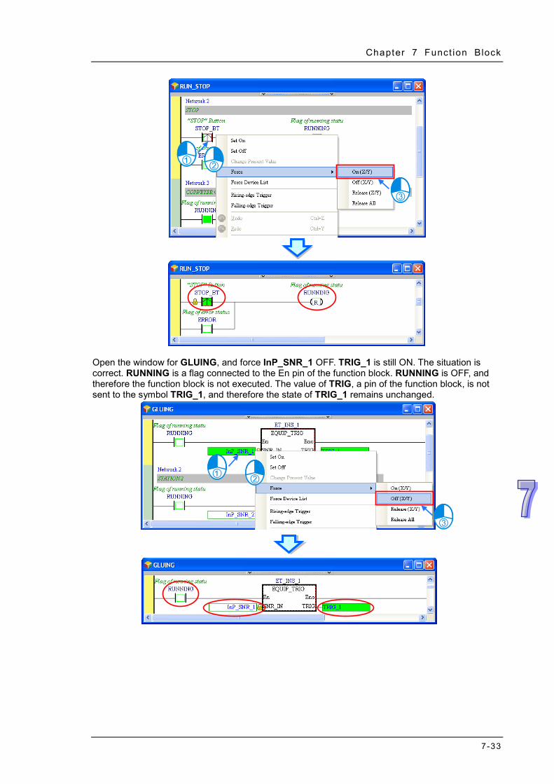
Chapter 7 Funct ion Block
7-33
Open the window for GLUING, and force InP_SNR_1 OFF. TRIG_1 is still ON. The situation is correct. RUNNING is a flag connected to the En pin of the function block. RUNNING is OFF, and therefore the function block is not executed. The value of TRIG, a pin of the function block, is not sent to the symbol TRIG_1, and therefore the state of TRIG_1 remains unchanged.

ISPSoft User Manual
7-34
Set TRIG_1 to OFF.
Open the window for ET_INS_1. TRIG in the window remains ON. This indicates that the states of the symbols in a function block will be retained after the function block is executed.
Open the window for ET_INS_2. TRIG in the window is OFF. The state of TRIG in the window for ET_INS_2 is different the state of TRIG in the window for ET_INS_1. This indicates that the function block instances operate independently.
After the users follow the steps above, they can draw the following conclusions. 1. If the flag connected to the En pin of a function block is OFF, the program in the function block will
not be executed. 2. The states of the symbols in a function block will be retained after the function block is executed. 3. The function block instances in a project operate independently. Obviously, the execution of the program in this section is different from the execution of the program in section 6.3. In the program in section 6.3, TRIG_1 is OFF when the flag RUNNING is OFF. In the program in this section, TRIG_1 is ON when the flag RUNNING is OFF. This is an expectable and acceptable situation. In the plan for the equipment, TRIG_1 is set to OFF so that it can be set to ON next time. As a result, the function of the equipment will not be affected even if the state of TRIG_1 remains unchanged when the equipment stops running. Please refer to section 4.1 for more information about the plan for the equipment.
7.5 Knowing the Library Library contains User Defined Library and Delta Library. A function block can be exported to the User Defined Library and can be used in other projects. There are several function blocks for various applications stored in the Delta Library for users to apply.
7.5.1 Creating the User-defined Library
When there is a function block created in a project, the function block can be exported to the user-defined library and by doing so, the function block can be used in other projects. Right click the Function Blocks under the Project node and click Export Function Blocks.

Chapter 7 Funct ion Block
7-35
After that you will see the Export Function Blocks window, type the file name, select the option Export to User Defined Library and click to select the function blocks you’d like to export. File name is used for categorization; one file can contain more than 1 function block. After the setup is done, click OK to confirm the setting. Click OK again once the Export Successfully window show up.
Click the User Defined Library tab and you will see the exported function blocks in this section.
Click on the Function Block, its properties will be shown in the Preview section.

ISPSoft User Manual
7-36
7.5.2 Including the Function Blocks in the User Defined Library
Aforementioned, once a function block is exported to the User Defined Library, users can find the exported function block in the User Defined Library when opening a new project in the same computer. Through the following methods, users can include the function to the function block. Method 1: Right click the Function Blocks under the Project node and click Include Function Blocks.
After that you will see the Include Function Blocks window, select the function that you’d like to include and click OK. Click Cancel to close the window. After that you will see the newly included function under the Function Blocks node.
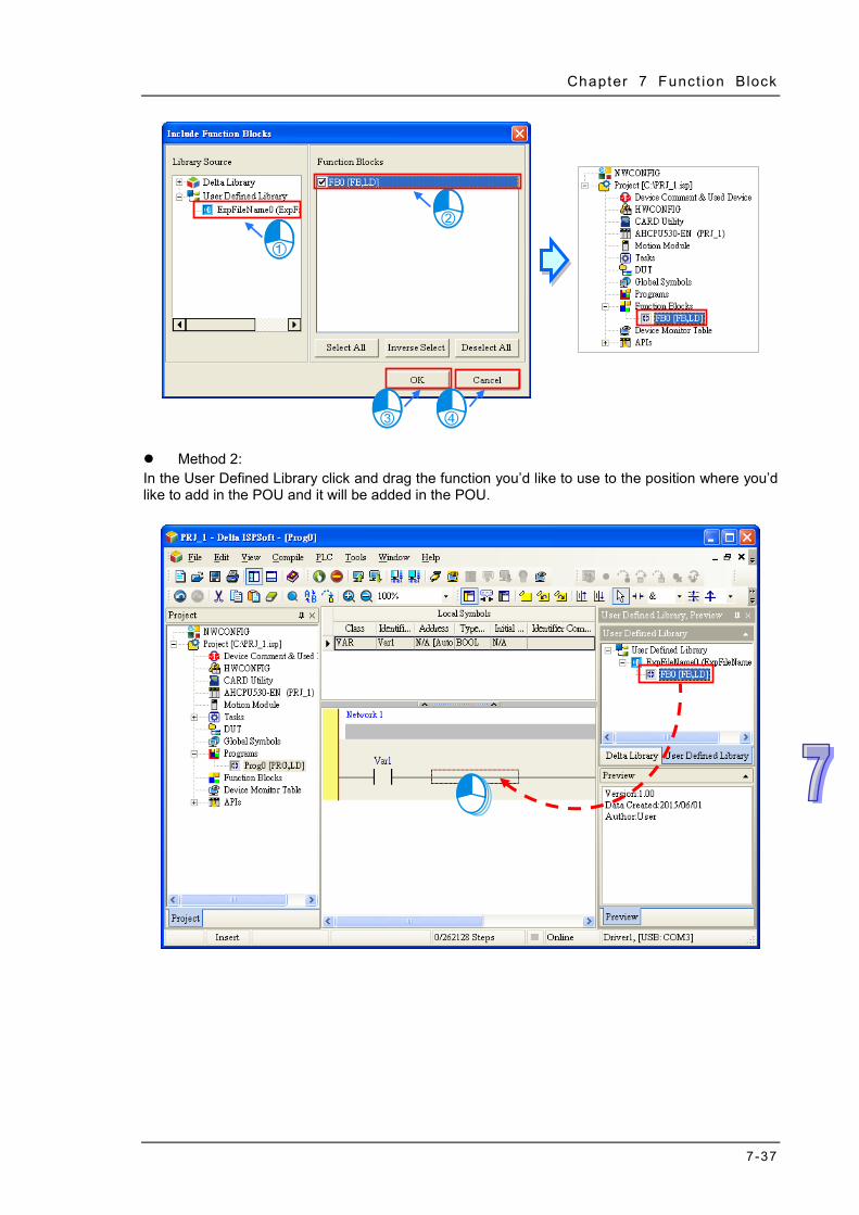
Chapter 7 Funct ion Block
7-37
Method 2: In the User Defined Library click and drag the function you’d like to use to the position where you’d like to add in the POU and it will be added in the POU.

ISPSoft User Manual
7-38
After that you will see the newly added function under the Function Blocks node.
7.5.3 Using Delta Library
For various applications, Delta provides several function blocks stored in the Delta Library for users to apply. Click the Delta Library tab to see the provided function blocks.
Through the following methods, users can include the function to the function block. Method 1: Right click the Function Blocks under the Project node and click Include Function Blocks.
Nodes added here.

Chapter 7 Funct ion Block
7-39
After that you will see the Include Function Blocks window, select the function that you’d like to include and click OK. Click Cancel to close the window. After that you will see the newly included function under the Function Blocks node.
Method 2: In the Delta Library click and drag the function you’d like to use to the position where you’d like to add in the POU and it will be added in the POU.

ISPSoft User Manual
7-40
After that you will see the newly added function under the Function Blocks node.
*1. For the function blocks in the Delta Library, the contents are not for users to open to view or edit.

8-1
Chapter 8 Data Unit Type Table of Contents 8.1 User-defined Data Type/Data Unit Type.................................................... 8-2 8.2 Structure…………………………………………………………………………8-2
8.2.1 Definition of a Structure ...................................................................... 8-2 8.2.2 Creating a Structure ........................................................................... 8-2 8.2.3 Using a Structure Variable ................................................................. 8-4 8.2.4 Applications of Structures ................................................................... 8-5
8.3. Enumeration.………………....................................................................... 8-7 8.3.1 Definition of Enumeration ................................................................. 8-7 8.3.2 Creating an Enumeration ................................................................... 8-7 8.3.3 Using an Enumeration Variable .......................................................... 8-9 8.3.4 Applications of Enumerations ........................................................... 8-10

ISPSoft User Manual
8-2
8.1 User-defined Data Type/Data Unit Type Sometimes basic data types are not sufficient for users to write their own programs for the PLC. In the IEC 61131-3 standard, a high-level language such as the user-defined data type is adopted to create a new data type as users desired, allowing users to define their own variables and improving the readability and the efficiency of developing a program. 8.2 Structure
8.2.1 Definition of a Structure
A structure is the collection of data, consisting of same amount various data types. Structured or array elements can be elements for other structures. A structure is used for grouping data and can be seen as a data unit to transfer parameters.
8.2.2 Creating a Structure Right-click DUT (Data Unit Type) in the project management area to see the option New. Click New to bring out a New DUT window. Input a structure name, select the type as Structure and then click OK to confirm the setting. After that, a new DUT with name and type will appear under the DUT option.
*. The naming rules of a structure and an element can be found below.
After the creation of the DUT is made, an editing window will be presented with examples and definitions for reference. Users can edit the examples to make them as their own structures.

Chapter 8 Data Uni t Type
8-3
Users can also find it under the DUT option in the project management area. Double click the new DUT to open it and start to add the contents of the newly added DUT.
The structure format is stated as below: wordings in blue are the system keywords; wordings in black are the user-defined structure names and element names. TYPE <Structure Name>: STRUCT <Element 1 Name>: <Data Type>; <Element 2 Name>: <Data Type>; ... <Element N Name>: <Data Type>; END_STRUCT END_TYPE Structure Name: Define the structure name. It is recommended to use the same name as the
name shown on the project management area. Element Name: Define the element name. Data Type:Define the data type for every element, such as BOOL, WORD, DWORD, LWORD,
INT, DINT, LINT, REAL, LREAL, ARRAY, other structures, enumerations and so on. As the image shown below, when the element data type is ARRAY, the format will be ARRAY [0..n] OF <data type>; the maximum for n value is 65535. If the element data type is Structure, write another structure name. But if the data type is ARRAY, users cannot import ARRAY again. The system supports multi-dimensional array, up to three-dimension. The format of a two-dimensional array is ARRAY [0..n] [0..n] OF <data type> and the three-dimensional array is ARRAY [0..n] [0..n] [0..n] OF < data type>. As the image shown below:
The naming rules of a structure and an element are stated as below. An identifier cannot be the same as names of the user-defined data types. The repetition of a

ISPSoft User Manual
8-4
structure identifier is not allowed. The repetition of an element identifier in the same structure is not allowed. The identifiers of a structure and an element can be composed of 30 characters at most, and a
Chinese character takes two characters. It is not allowed to use a name reserved by the system, e.g. an instruction code, a device name,
or a name given a special significance. However, if a name reserved by the system is a part of the names of a structure or an element, it is then a legal name. For example, “M0” is an illegal
name, but “_M0” is a legal name.
The identifiers of a structure and an element cannot contain space. For example, “INPUT CH0” is an illegal name.
The identifiers of a structure and an element can contain underline but it is not allowed to use 2 underlines in a row or put it in the end. For example, “INPUT_CH0”is acceptable, but
“INPUT__CH0” and “INPUT_CH0_” are illegal. The identifier of a structure and an element cannot contain special characters, including *, #, ?, \,
%, @ and more.
8.2.3 Using a Structure Variable
After the creation of the structure type is done, users can declare the variable symbol in the Local Symbols page. Open the Add Symbol window from the Global and local symbol table and input the identifier and then click …on the right as the image shown below.
Select the Data Unit Type, and the declared structure data type and then click OK to add a new symbol.

Chapter 8 Data Uni t Type
8-5
8.2.4 Applications of Structures
After the structure and symbol are declared, they can be used in the POU. The data type of the
symbol struct_var0 is Struct_0 in the function block as the image shown below. Users can use “.”
to assign the element for the structure symbols, for example struct_var0.pt1 means the first
element pt1 is assigned as a contact to the data type BOOL operand and struct_var0.pt2 means
the second element pt2 is assigned as a pin to the data type WORD operand as the image shown
below.

ISPSoft User Manual
8-6
When using the aforementioned function block, Struct_0 data type symbol should be declared in the POU, so that Struct_0 data type input pin and output pin can be consistent. The elements with the same structure can use “.” to assign the element for the structure type symbols, for example POUstruct_var.
From the description above, we know that when the structure type symbol POUstruct_Var is used in the FB0, it also delivers all the elements from the symbol for struct_var0.pt1 and struct_var0.pt2 to operate. Thus users can define the structure type symbols as the input/output pin for the function block to deliver all the elements from the symbol. So that the pin defining time can be saved and the program can be simpler.
POUWord_Var POUstruct_Var
struct_var0.pt1
struct_var0.pt2
FB0_inst

Chapter 8 Data Uni t Type
8-7
When the structure is constructed with an array element, the variables in the structure can be written as the example shown below: the status of M0 can be written in the [1,1,1] of the appointed element pt3 in the variable Pstruct_var1.
8.3. Enumeration
8.3.1 Definition of Enumeration
Users can enumerate (obtain one at a time) the elements in a collection of objects, providing an efficient way to define a set of named integral constants that may be assigned to a variable and values that the enumeration represents.
8.3.2 Creating an Enumeration
Right-click DUT (Data Unit Type) in the project management area to see the option New. Click New to bring out a New DUT window. Input an enumeration name, select the type as Enumeration and then click OK to confirm the setting. After that, a new DUT with name and type will appear under the DUT option.
*. The naming rules of an enumeration can be found below.
After the creation of the DUT is made, an editing window will be presented with examples and definitions for reference. Users can edit the examples to make them as their own enumerations.

ISPSoft User Manual
8-8
Users can find it under the DUT option in the project management area. Double click the new DUT to open it and start to add the contents of the newly added DUT.
The enumeration format is stated as below: wordings in blue are the system keywords; wordings in black are the user-defined enumeration names, element names and values. TYPE <Enumeration Name>:
( < Element 1 Name > := <Value 1>, < Element 2 Name > := <Value 2>, ... < Element n Name > := <Value n>
); END_TYPE Enumeration Name: Define the enumeration name. It is recommended to use the same name as
the name shown on the project management area. Element Name: Define the element name. Value: Define values for every element, ranging -32768~32767. It is acceptable to leave this field

Chapter 8 Data Uni t Type
8-9
blank. The system will use defaults according to the previous element value and avoid duplications. The system will set the value of the element Blue to 1 and Yellow to 6 as the image shown below.
The naming rules of an enumeration and an element are stated as below. An identifier cannot be the same as names of the user-defined data types. The repetition of a
enumeration identifier is not allowed. The repetition of an element identifier in the same enumeration is not allowed. The identifiers of an enumeration and an element can be composed of 30 characters at most, and
a Chinese character takes two characters. It is not allowed to use a name reserved by the system, e.g. an instruction code, a device name,
or a name given a special significance. However, if a name reserved by the system is a part of the names of a structure or an element, it is then a legal name. For example, “M0” is an illegal name, but “_M0” is a legal name.
The identifiers of an enumeration and an element cannot contain space. For example, “INPUT CH0” is an illegal name.
The identifiers of an enumeration and an element can contain underline but it is not allowed to use 2 underlines in a row or put it in the end. For example, “INPUT_CH0”is acceptable, but “INPUT__CH0” and “INPUT_CH0_” are illegal.
The identifier of an enumeration and an element cannot contain special characters, including *, #, ?, \, %, @ and more.
8.3.3 Using an Enumeration Variable
After the creation of the enumeration type is done, users can declare the symbol in the Local Symbols page. Open the Add Symbol window from the Global and local symbol table and input the identifier and then click … on the right as the image shown below.
Select the Data Unit Type, and the declared structure data type and then click OK to add a new symbol.

ISPSoft User Manual
8-10
8.3.4 Applications of Enumerations
After the enumeration and symbol are declared, they can be used in the POU. The data type of the symbol POUenum_Var0 is Enum_0. The Initial Value can be set by the element name or values. The image below shows the element name, Red. Users can use “.” to assign the element for the enumeration symbols, for instance, users can assign Enum_0.Blue to POUenum_Var0, the symbol Enum_0, and execute the instruction MOV; the defined element or value will be the enumeration value and after the execution of MOV, the value of POUenum_Var0 will be 1.

Chapter 8 Data Uni t Type
8-11
Users can also perform numerical operations; using the instruction + and set the value to 1, POUenum_Var0 will be incremented by 1 as the example shown above. When the value of POUenum_Var0 is 1, after executing the instruction +, the value result will be 2 and its element will be Green as defined. When running and monitoring the program, the enumeration symbols will show their current defined element names. For example when the value is 1, the POUenum_Var0 will be seen as POUenum_Var0=Blue(1) as they are defined in the following image. But if the value of the enumeration symbol is not in the defined element range, the value will be shown as it is; as the following example shows when the value is 11 but 11 is not in the defined range, POUenum_Var1=11 will be stated as the image shown below.

ISPSoft User Manual
8-12
MEMO

9-1
Chapter 9. Axis
Table of Content
9.1 Axis ............................................................................................................ 9-2 9.1.1 The Meaning of Axis ...................................................................... 9-2 9.1.2 Creating a New Axis ...................................................................... 9-2 9.1.3 Main Table and Axis Table under Global Symbols ......................... 9-3
9.2 Axis Parameter and Monitor & Test Run .................................................... 9-4 9.2.1 Axis Parameter .............................................................................. 9-4 9.2.2 Monitor & Test Run ........................................................................ 9-8

ISPSoft User Manual
9-2
9.1 Axis
9.1.1 The Meaning of Axis
As defined in the PLCopen MC standard, Axis on the software is the VAR_IN_OUT parameter of the STRUCTURE data type used in motion control function blocks. Axis provides a connection between the motion control in the program and the physical output device. Axis stores various motion control information such as position, velocity and so on. Below is an example of one function block defined in the PLCopen MC standard and AXIS_REF being the axis defined in the standard.
In the actual application, different motion function blocks are used to control an axis and then the target servo motor receives the output to achieve the motion control.
9.1.2 Creating a New Axis Right-click Axis in the project management area and then click New on the context menu. The New Axis window will appear. Type an axis variable name under Axis Variable and click OK button in the following window to add the node item under Axis in the project management area. Make sure that the axis variable name should not be the same as other global variable names or local variable names.
The full name of the node item under Axis contains the axis variable name and axis type mentioned above. The axis type here which is the same as that in the parameter setting can be the EtherCAT

Chapter 9 Ax is
9-3
slave name and the station address of a virtual or real axis. There are two sub-items, Axis Parameter and Monitor & Test Run under every node. Refer to the following sections for more information.
Right-click the axis which has been built and then select Delete button on the context menu to delete the axis or select Property button to reset the axis variable name.
9.1.3 Main Table and Axis Table under Global Symbols For management of the symbols by classification, there are different sub-items including Main Table, Axis Table and other network symbol table under Global Symbols. Main Table, the global symbols of other models, is used for editing the global symbols. Axis Table lists all axis variable names which have already been created. Other network symbol table contains the symbols in other network configuration software such as ECAT Builder supported by the model. For details on other network configuration software, refer to operation manuals of the software.
After the axis is created, the identifier of the axis variable name will appear automatically in Axis Table under Global Symbols. Double-click Axis Table to open the Axis Table window.
Axis Variable Name (Axis Type)

ISPSoft User Manual
9-4
The content in the Axis Table window can not be edited. Users can only right-click the Node item in the project management area and select New, Delete and Property button on the context menu to add and delete the axis item and its identifier or modify the axis variable name as described in section 9.1.2. The axis variable symbol can be used for the pins of PLCopen MC function blocks and Delta function blocks as the example shown below.
9.2 Axis Parameter and Monitor & Test Run
9.2.1 Axis Parameter
AxisParaForm, the parameter setting window of the axis will be opened automatically once the axis node item is created. Users can double-click Axis Parameter under the axis node item to open the AxisParaForm window once more after the window is closed. All settings on motion control of the axis are listed in the window as below. For details, refer to the user manuals of modules. The set values can be downloaded to the PLC with the project together after the setting is done. Refer to section 16.1.2 on how to upload and download the settings.

Chapter 9 Ax is
9-5
Axis Type Setting Users can set the real axis which produces actual output to the drive assembly or the virtual servo axis on which the operation is done in the controller. Servo Axis Form Setting The axis can be set as Linear axis or Rotary axis. The position value will be constantly increased (or decreased) when the linear axis rotates toward the positive direction (or negative direction). The position value will be calculated again from minimum (maximum) value after the axis which rotates toward the positive direction (or negative direction) reaches the limit value. Node Address Setting If Real axis is selected in the Axis Type Setting box, the content in Node Address Setting must be chosen by the servo names and station addresses in ECAT Builder. It means that the axis is the set EtherCAT servo drive to which the actual output is delivered. The node address is selected as the EtherCAT slave, ASDA-A2-E CoE Drive [5] (the station address) as below.
Unit of Display Setting Users can select a system unit. Motor means the pulse unit and Machine is the unit of the length or angle. Pulse Count Per Motor Rotation Users can set how many pulses the controller outputs for a motor to rotate. Distance Count Per Motor Rotation Users can set the distance in an actual mechanism move whenever a motor rotates. Maximum speed setting Users can set the upper limit of the speed of the axis. Start-up speed setting Users can set the start-up speed for the axis to start running. Maximum Acceleration Setting Users can set the upper limit of the acceleration of the axis. Maximum Deceleration Setting Users can set the upper limit of the deceleration of the axis.

ISPSoft User Manual
9-6
Axis Stop Method Setting Users can set the axis stopping method, when an error occurs. The option Immediate Stop or Deceleration Stop can be selected. Software Limit Input Stop Method Users can set the axis stopping method, when the axis runs beyond the software limit set. The option Immediate Stop or Deceleration Stop can be selected. Compensation value for the axis Users can set the compensation value of a screw rod connected to the axis for a better control precision. Software Limit Enable Setting Users can set whether to enable or disable the software limit control and the limit values depend on the following two parameters. Axis software positive limit Setting Users can set the positive software limit value of the axis, which is only applied to the linear axis. Axis software negative limit Setting Users can set the negative software limit value of the axis, which is only applied to the linear axis. Rotary Maximum Position Setting Users can set the maximum position of the rotary axis which moves toward the positive direction. The position value will be calculated again from the minimum value after the axis reaches the limit value. Rotary Minimum Position Setting Users can set the minimum position of the rotary axis which moves toward the negative direction. The position value will be calculated again from the maximum value after the axis reaches the limit value. Gear Ratio Denominator Users can set the denominator value of the electronic gear ratio. Gear Ratio Numerator Users can set the numerator value of the electronic gear ratio.

Chapter 9 Ax is
9-7
Homing Velocity The parameter is the speed while the homing is performed Homing Closed Velocity While the homing is performed, the motor moves at the homing velocity at first. Then the motor starts to decelerate to this velocity and moves at this velocity when the trigger is close to the home signal. The axis parameter setting window provides the following tool bar for editing the axis parameter table.
Search Tool: After a character string is typed, relevant character strings will be listed automatically. If one item in the list of relevant character strings is selected, the corresponding line in the table will be selected accordingly.
After the button is clicked, the parameter values different from the default values will be filtered out.

ISPSoft User Manual
9-8
After the button is clicked, all setting values will be restored to the default values. If the button is clicked, current parameters can be exported to the specified path in the file format of .CSV. If the button is clicked, the file at the specified path can be imported.
9.2.2 Monitor & Test Run
Double-click Monitor &Test Run under Axis to open the Monitor & Test Run window after ISPSoft enters the online mode.

Chapter 9 Ax is
9-9
The upper part of the window above is a monitor window for displaying the axis state, the set value and actual value of a variable such as positions and velocities.
The bottom part of the window is a test-run window for giving a test-run command to the axis after hardware connection is made in the period of the test. After the Fetch button is clicked, the Confirm window will appear for confirmation of the control over the axis. Please note that the field configuration and personnel’s positions must be confirmed in order to make sure that no injury to personnel and no damage to devices when the motor works before the test run of the axis is started.

ISPSoft User Manual
9-10
To exit the test-run mode, click the Relinquish button to stop having the control over the axis. Click Servo ON button to turn on or Servo OFF button to turn off the servo drive after having the control over the axis.
When Servo ON is clicked, various test-run modes in the Mode field are for option. There are different execution functions for users to type under various modes. The corresponding functions are explained as below. Homing Mode: Perform the homing according to the axis parameter setting and type the homing mode number in the Homing Mode field based on the 35 homing modes in CANopen standard. Click the Execute button to start the homing. Click Stop to abort the homing action.
Jog: Execute the jog action according to the jog velocity in the axis parameter setting. After typing the jog velocity in the Velocity field, execute the backward jog or forward jog by clicking the Backward Jog or Forward Jog button.

Chapter 9 Ax is
9-11
Velocity: Type the values in the Velocity, Acceleration Time and Deceleration Time fields. If the Forward or Negative button is clicked, the drive will accelerate till the set velocity is reached according to the set acceleration time and then keep moving in the forward or backward direction. By clicking Stop, the axis will decelerate to stop according to the set acceleration time.
Relative Positioning: Type values in the Position (adding + or -),Velocity, Acceleration Time and Deceleration Time fields. After the Enabled button is clicked, the drive will accelerate till the set velocity is reached and keep moving according to the set acceleration time. And then the drive decelerates to stop and finally reaches the relative position according to the set deceleration time. Clicking Stop will abort the action during the motion.
Absolute Positioning: Type values in the Position, Velocity, Acceleration Time and Deceleration Time fields. After the Enabled button is clicked, the drive will accelerate till the set velocity is reached and keep moving according to the set acceleration time. And then the drive decelerates to stop and finally reaches the absolute position according to the set deceleration time. Clicking Stop will abort the action during the motion.

ISPSoft User Manual
9-12
MEMO

10-1
Chapter 10 Ladder Diagram Table of Contents 10.1 Introduction of a Ladder Diagram ........................................................10-2
10.1.1 Editing Environment ......................................................................10-2 10.1.2 Networks in a Ladder Diagram .....................................................10-4 10.1.3 Selecting Objects ..........................................................................10-5
10.2 Creating a Ladder Diagram in ISPSoft .................................................10-6 10.2.1 Creating a Contact and a Coil .......................................................10-6
10.2.1.1 Inserting a Contact and Changing a Contact Type ................10-6 10.2.1.2 Inserting a Coil and Changing a Coil Type .............................10-7
10.2.2 Using Devices, Symbols, and Constants in a Ladder Diagram .....10-8 10.2.3 Typing Instructions ........................................................................10-9 10.2.4 Inserting Applied Instructions and Function Blocks.....................10-10 10.2.5 Creating a Comparison Contact ..................................................10-12 10.2.6 Inserting a Block Logic Instruction ..............................................10-14 10.2.7 Creating Multiple Outputs ...........................................................10-16 10.2.8 Putting a Label ............................................................................10-17 10.2.9 Editing a Comment .....................................................................10-18 10.2.10 Symbol Mode and Address Mode ...............................................10-19 10.2.11 Bookmark ...................................................................................10-20 10.2.12 Activating/Inactivating a Network ................................................10-21

ISPSoft User Manual
10-2
10.1 Introduction of a Ladder Diagram A ladder diagram is one of the programming languages defined by IEC 61131-3, and is widely used to create a PLC program. A ladder diagram is a programming language that represents a program by a graphical diagram based on the circuit diagrams of relay logic hardware. A ladder diagram in ISPSoft is shown below.
*. Please refer to DVP-PLC Application Manual─Programming for more information about ladder diagrams.
10.1.1 Editing Environment
Select the Ladder Diagram (LD) option button in the Language section in the Create Program window. Please refer to section 5.4.1 for more information.

Chapter 10 Ladder Diagram
10-3
The environment in which a ladder diagram can be edited is shown below. The table at the upper part of the window is a local symbol table, and the area at the lower part of the window is a working area.
After a program editing window in which a ladder diagram can be created is opened, the corresponding toolbar will appear in the ISPSoft window. The functions are described below.
Icon Keyboard shortcut Function
Display/Hiding symbol or address
Shift+Ctrl+C Displaying/Hiding the comments on the networks
None Displaying/Hiding the commands on the devices
Shift+Ctrl+A Activating/Inactivating the network selected
Shift+Ctrl+B Adding a bookmark to the network selected or deleting the
bookmark from the network selected
Shift+Ctrl+P Going to the previous bookmarked position
Shift+Ctrl+N Going to the next bookmarked position
Ctrl+I Inserting a network above the network selected
Shift+Ctrl+I Inserting a network under the network selected
ESC Selection
Typing an instruction Inserting a contact
Typing an instruction Inserting a coil
Typing an instruction Inserting a comparison contact
Typing an instruction Selecting a type of comparison contact
Typing an instruction Inserting a block logic instruction
(NP/PN/INV/FB_NP/FB_PN)
Typing an instruction Selecting a type of block logic instruction
Shift+Ctrl+U Inserting an instruction or a function block
Local symbol table
Working area

ISPSoft User Manual
10-4
*. Please refer to section 8.2.3 for more information about typing an instruction.
10.1.2 Networks in a Ladder Diagram
A ladder diagram consists of networks. Every network is an independent program. Besides, there is no limit on the number of objects which can be inserted in a network in ISPSoft, and therefore there is no mark which is used to connect two networks. Network numbers are marked on the networks in a ladder diagram. The color at the left side of a network indicates the state of the network. A network can be activated or inactivated, and a network can be selected or unselected. Users can select colors which will be shown at the left sides of the networks in a ladder diagram in the Options window in ISPSoft. Please refer to section 2.3.1 for more information.
After a new window in which a ladder diagram will be created is opened, the system will insert a blank network in the window. If users want to add a network, they can select a network, and click
on the toolbar. The network added will be under the network selected.
If users click on the toolbar, a blank network will be put above the network selected.
The network is unselected and inactivated.
The network is selected and inactivated.
The network is unselected and activated.
The network is selected and activated.

Chapter 10 Ladder Diagram
10-5
10.1.3 Selecting Objects
Before an object in a network in a ladder diagram is selected, users have to press Esc on the keyboard, or click on the toolbar. After the cursor appears as a small arrow, the users can click the object in the network. The basic selection is shown below.
Selecting the network
Selecting the input contact
Selecting the network
Selecting the output coil
Selecting the block If users want to select a group of devices, they can click a device, and drag it to draw a frame round the group of devices. The users can also select the group of devices by clicking the first device, pressing Ctrl+B on the keyboard, clicking the last device, and pressing Ctrl+B on the keyboard. Users must draw a frame round devices which are in the same network, and the devices must be adjacent to one another. Besides, input devices and output devices can not be in the same frame.
If users want to select several networks, they can hold down Ctrl on the keyboard while they click the networks. The users can also select a range of networks by pressing Shift on the keyboard, clicking the first network within the range, and the last network within the range.

ISPSoft User Manual
10-6
10.2 Creating a Ladder Diagram in ISPSoft
10.2.1 Creating a Contact and a Coil
The representations of contacts and the representations of coils in ISPSoft are listed below.
Contact
Normally-open contact
Normally-closed contact
Rising edge-triggered contact
Falling edge-triggered contact
Coil OUT
SET
Coil RESET
10.2.1.1 Inserting a Contact and Changing a Contact Type
(1) Select a line, a contact, or a group of devices. Before users connect a contact to a group of devices in parallel or in series, they have to draw a frame round the group of devices. After users make sure of the position in which a contact will be inserted, they can click on the toolbar.
(2) The mouse cursor appears as a contact when the mouse cursor is near the position in which a contact will be inserted. If the mouse cursor is near a contact, a contact will be connected to the contact in parallel
or in series.
If the mouse cursor is near a line, a contact will be inserted in the line.

Chapter 10 Ladder Diagram
10-7
If the mouse cursor is near a group of devices, a contact will be connected to the group of devices in parallel or in series.
If users want to insert a contact in a new network, they can move the mouse cursor to the
red frame in the new network.
(3) The mouse cursor appears as a contact when the mouse cursor is at the right side of a contact,
at the left side of a contact, or at the bottom of a contact. Users can decide where to insert a contact. After users click the position in which a contact will be inserted, the system will insert the contact.
(4) After a contact is inserted, users can click on the toolbar or press Esc on the keyboard.
After the contact is double-clicked, users can select a contact type on the drop-down list.
10.2.1.2 Inserting a Coil and Changing a Coil Type
(1) Select a line, a contact, a coil, or an applied instruction. After users make sure of the position in which a coil will be inserted, they can click on the toolbar.
(2) The mouse cursor appears as a coil when the mouse cursor is near the position in which a coil
will be inserted. If the mouse cursor is at the top of a coil or at the top of an applied instruction, a coil will be put above the coil or the applied instruction. If the mouse cursor is at the bottom of a coil or at the bottom of an applied instruction, a coil will be put under the coil or the applied

ISPSoft User Manual
10-8
instruction. If the mouse cursor is near the line in a network, a coil will put above all the output devices in the network. After users click the position in which a coil will be inserted, the system will insert the coil.
If users want to insert a coil in a network where there is no output device, the mouse cursor must be near the line selected.
(3) After a coil is inserted, users can click on the toolbar or press Esc on the keyboard. After
the coil is double-clicked, users can select a coil type on the drop-down list.
10.2.2 Using Devices, Symbols, and Constants in a Ladder Diagram
After users click ??? above an object inserted in a network, they can type an operand.
The users can click in the box, and select a declared symbol on the drop-down list. Select an ARRAY data type symbol from the drop-down list and type an element in the […]. See below for ARRAY element descriptions.
The users can type a device name or a symbol in the box. If they type a symbol which is not declared, the Add Symbol window will appear after they press Enter on the keyboard. (Please refer to section 2.3.1 for more information about declaring a symbol.)

Chapter 10 Ladder Diagram
10-9
After users click a network and press Enter on the keyboard, they can edit a box. The users can edit the next box in the network after they press Enter on the keyboard. Besides, the next network will be selected after the users press Tab on the keyboard. The users can edit a box with the keyboard. If the users have declared symbols, they can press Page Down on the keyboard when they edit a box. The symbols on the drop-down list are symbols which can be assigned to the operands. The users can select a symbol by the mouse or the up/down key on the keyboard. After the editing is complete, the users can press Enter on the keyboard to jump to the next box. If the users want to end the editing, they can press Esc on the keyboard. Additional remark (a) If users want to use constants in a ladder diagram in ISPSoft, the constants must be
represented in the following ways. Decimal value: 23456 (A value which is not preceded by any mark will be regarded as a
decimal value.) Hexadecimal value: 16#5BA0 (A value is preceded by 16#.) Octal value: 8#55640 (A value is preceded by 8#.) Binary value: 2#101101110100000 (A value is preceded by 2#.) String: “XYZ” (Characters are put in double quotes.) Boolean value:
AH/AS: SM400 (normally-open contact), or SM401 (normally-closed contact) is used. DVP: M1000 (normally-open contact), or M1001 (normally-closed contact) is used.
(b) If users want to use a symbol whose data type is ARRAY, the expression format is as the image shown above Ary[…] (Identifier[Index]). An index should be a decimal constant, less than the size of the ARRAY and should start from 0, supporting up to three-dimensional array and separating by a comma, for example Ary[1,2,3]. Since the Ladder Diagram (LD) does not support variable type index. The indexes in a ladder diagram can not be symbols.
10.2.3 Typing Instructions
Users can add devices, applied instructions and function blocks to a ladder diagram in ISPSoft by typing instructions. (1) Select a position in which an object will be inserted in a working area.
(2) Type an instruction. As soon as the instruction is typed, a box which can be edited appears.
After the typing of the instruction is complete, users can press Enter on the keyboard or click OK at the right side of the box. (The instruction is case-insensitive.)
Besides, contacts and coils can be created by typing simple instructions. Please refer to the following figures. (The instructions typed are case-insensitive.) Inserting a normally-open contact (contact A): “A Device address”

ISPSoft User Manual
10-10
Inserting a normally-closed contact (contact B): “B Device address”
Inserting an output coil (OUT): “O Device address”
10.2.4 Inserting Applied Instructions and Function Blocks
The applied instructions and function blocks in a ladder diagram in ISPSoft are represented by blocks. The pins of a block representing an applied instruction include the pins corresponding to the operands specified in the applied instruction and an En pin. The pins of a block representing a function block include the pins corresponding to the symbols declared in the function block and an En pin. The En pin of a block representing an applied instruction or a function block is connected to the logic state preceding the En pin. If the logic state connected to the En pin of a block representing an applied instruction or a function block is ON, the applied instruction or the function block will be executed. The pins of a block representing a function block include an Eno pin whereas the pins of a block representing an applied instruction do not include an Eno pin. An applied instruction can only be put at the end of a network in a ladder diagram, and can not be followed by any object. Besides, users can type a function block instance in the box above a function block. Please refer to chapter 7 for more information.
Users can insert an applied instruction or a function block in a ladder diagram in ISPSoft in one of the three ways described below. Method 1
Unfold the APIs section or the Function Blocks section in the project management area, and find the item which will be inserted. Select the item, and drag it to the position in which it will be inserted.

Chapter 10 Ladder Diagram
10-11
Function block definitions can be dragged, but function block instances can not be dragged.
Method 2
Click the position in which an applied instruction or a function block will be inserted, click on the toolbar, select the item which will be inserted in the API/FB window, and click Insert.
Users can select the All Types option button, the Comparison Instruction option button, the
API option button, or the Function Block option button.
If users select the API option button in the Type Class section, they have to select an instruction type in the Classification box.
Users can select an applied instruction, a comparison contact, or a function block here.
If users unselect the Auto Close checkbox, they can insert instructions or function blocks continuously.
Method 3
Click the position in which an instruction or a function block will be inserted, and type the applied instruction or the function block definition. As soon as the applied instruction or the function block definition is typed, a box which can be edited appears. After the typing of the applied instruction or

ISPSoft User Manual
10-12
the function block definition is complete, users can press Enter on the keyboard or click OK at the right side of the box. (The applied instruction and the function block definition are case-insensitive.)
If users want to insert a function block, they have to type the function block definition, and they can not type the operands specifed in the function block. If users want to insert an applied instruction, they have to type the applied instruction, and they can type the operands specified in the applied instruction. The users do not have to type all the operands specified in the applied instruction. The system will assign the operands typed to the corresponding boxes, and ??? will appear in the boxes where there are no operands. Besides, if the operands typed include a symbol which is not declared, the Add Symbol window will appear after the users press Enter on the keyboard. Please refer to programming manuals for more information about instructions.
After an applied instruction or a function block is inserted successfully, users have to refer to section 10.2.2, and type operands.
*. If the Auto-leading ‘Add Symbol’ Dialog checkbox in the Options window is selected, the Add Symbol window
will appear automatically after users type a symbol which is not declared. Please refer to section 2.3.1 for more information.
10.2.5 Creating a Comparison Contact
An example of a comparison contact in ISPSoft is shown below. > in the block represents a comparison type. S1 and S2 are objects which are compared. The data format which is accepted depends on the comparison type. Q can drive a coil or connect to a contact in series.

Chapter 10 Ladder Diagram
10-13
The comparison contacts in a ladder diagram are similar to general contacts in that they can connect to other contacts in parallel or in series.
A comparison contact can be inserted not only in one of the three ways described in section 10.2.4, but also by means of the following steps. (1) Click on the toolbar, and then select a type.
(2) Select a line, a contact, or a group of devices. Before users connect a comparison contact to a
group of devices in parallel or in series, they have to draw a frame round the group of devices. After users make sure of the position in which a comparison contact will be inserted, they can click on the toolbar.
(3) The mouse cursor appears as a comparison contact when the mouse cursor is near the
position in which a comparison contact will be inserted. Please refer to the figures below. The mouse cursor appears as a contact when the mouse cursor is at the right side of the contact selected, at the left side of the contact selected, or at the bottom of the contact selected. Users can decide where to insert a comparison contact. After users click the position in which a contact will be inserted, the system will insert the contact.

ISPSoft User Manual
10-14
(4) After an comparison contact is inserted successfully, users have to refer to section 10.2.2, and
type operands.
Additional remark If users want to insert a comparison contact in a new network, the mouse cursor must be near the line selected.
10.2.6 Inserting a Block Logic Instruction
If users want to take the operation result of a block as a condition of a rising edge-triggered circuit, they traditionally have to create two networks in a ladder diagram. However, the users can combine the two networks by means of using a block logic instruction.

Chapter 10 Ladder Diagram
10-15
The block logic instructions that ISPSoft provides are as follows. Representation Instruction Function
NP When the block preceding this block logic instruction is tuned from OFF to ON, the output device is ON.
PN When the block preceding this block logic instruction is turned form ON to OFF, the output device is ON.
INV The operation result of the block preceding this block logic instruction is inverted, and the inversion result is sent.
FB_NP
This block logic instruction is similar to NP except that users have to specify a device or a variable in this block logic instruction. (FB_NP can only be used in the function blocks in AH/AS series CPU modules.)
FB_PN
This block logic instruction is similar to PN except that users have to specify a device or a variable in this block logic instruction. (FB_PN can only be used in the function blocks in AH/AS series CPU modules.)
* Please refer to AH/AS Programming Manual or section 7.3.2 for more information about FB_NP and FB_PN.
Users can insert a block logic instruction in one of the two ways described below. Method 1
(1) Click on the toolbar, and then select a type.
(2) Click on the toolbar.
(3) The mouse cursor appears as the representation of a block logic instruction when the
mouse cursor is near the position in which a block logic instruction will be inserted. Please

ISPSoft User Manual
10-16
refer to the figures below. The mouse cursor appears as the representation of a block logic instruction when the mouse cursor is at the right side of the contact selected, or at the left side of the contact selected. Users can decide where to insert a block logic instruction. After users click the position in which a block logic instruction will be inserted, the system will insert the block logic instruction.
Method 2
Click the position in which a block logic instruction will be inserted, and type the block logic instruction. As soon as the block logic instruction is typed, a box which can be edited appears. After the typing of the block logic instruction is complete, users can press Enter on the keyboard or click OK at the right side of the box. The representation of the block logic instruction typed will be put in front of the position selected. (The instruction typed is case-insensitive.)
10.2.7 Creating Multiple Outputs
(1) If users want to create multiple outputs, they have to insert a coil or an applied instruction first.
(2) Click or on the toolbar, move the mouse cursor to a position near the output object, and then click the left mouse button.

Chapter 10 Ladder Diagram
10-17
(3) Create multiple outputs according to the description above.
10.2.8 Putting a Label
If users want to use a jump instruction, they have to put a label on the network to which the execution of the program jumps. A label is put at the right side of a network number. Besides, if the project created is a project for a DVP series PLC, the label put on a network must be a P device. The P devices in an AH500 series CPU module are automatically assigned by the system, and can not be used by users. If the project created is a project for an AH500 series CPU module, the label symbol users type must be a unique label. The label symbol users type in a project for an AH500 series CPU module does not need to be declared in a symbol table. Please refer to user manuals for more information about P devices.
If users want to specify a label in an instruction, they do not have to type a colon in front of the label.
The steps of putting a label are as follows. (1) Click the right side of the network number at which a label will be put.
(2) If the project created is a project for a DVP series PLC, users have to type a P device number.
If the project created is a project for an AH500 series CPU module, users have to type a label symbol. Press Enter on the keyboard after a P device number or a label symbol is typed. The system will automatically put a colon at the right side of the label.

ISPSoft User Manual
10-18
10.2.9 Editing a Comment
In a ladder diagram in ISPSoft, users not only can make comments on the devices, but can make comments on the networks. Users can type comments under the network numbers in a ladder diagram in ISPSoft.
Editing the comment on a network (1) After users click on the toolbar, the comments on the networks will be displayed. If the
users click on the toolbar again, the comments on the networks will be hidden.
(2) After the users click the position under a network number, a box will appear.
(3) Type a comment in the box. If the users want to start a new line of text at a specific point,
they can press Shift+Enter on the keyboard. Press Enter on the keyboard after the editing is complete.
Editing the comment on a device
(1) After users click on the toolbar, the comments on the devices will be displayed. If the users click on the toolbar again, the comments on the devices will be hidden.
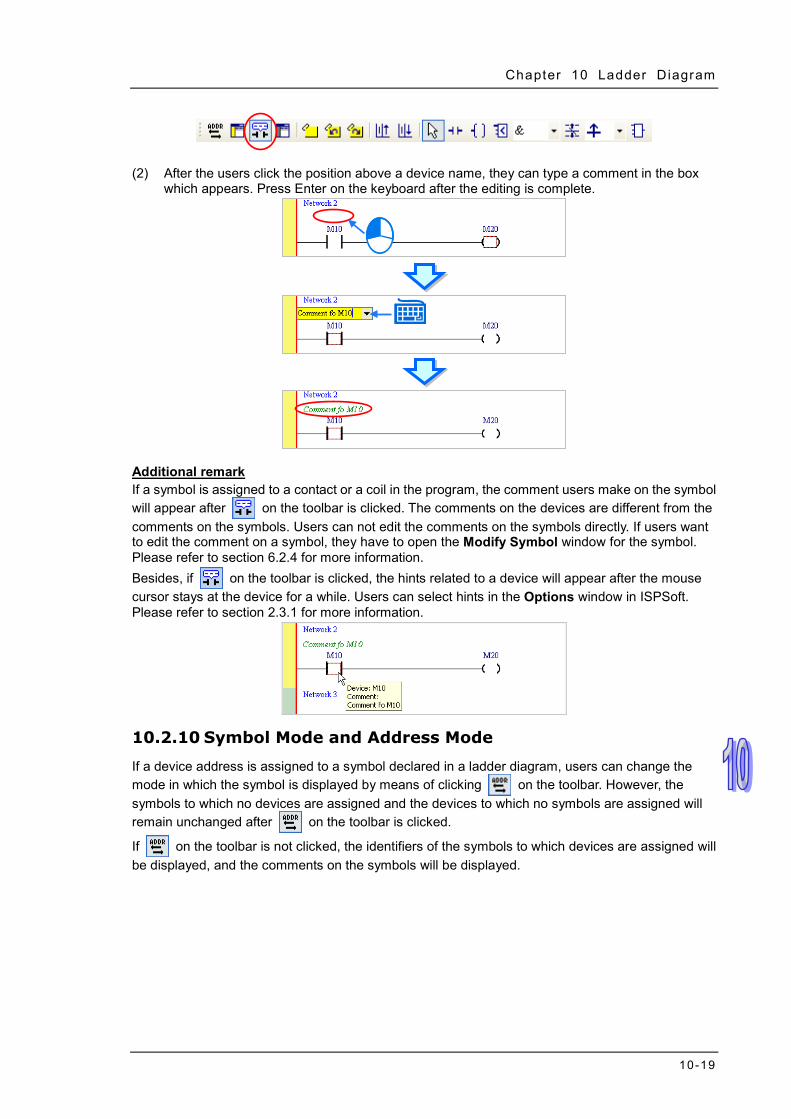
Chapter 10 Ladder Diagram
10-19
(2) After the users click the position above a device name, they can type a comment in the box which appears. Press Enter on the keyboard after the editing is complete.
Additional remark If a symbol is assigned to a contact or a coil in the program, the comment users make on the symbol will appear after on the toolbar is clicked. The comments on the devices are different from the comments on the symbols. Users can not edit the comments on the symbols directly. If users want to edit the comment on a symbol, they have to open the Modify Symbol window for the symbol. Please refer to section 6.2.4 for more information. Besides, if on the toolbar is clicked, the hints related to a device will appear after the mouse cursor stays at the device for a while. Users can select hints in the Options window in ISPSoft. Please refer to section 2.3.1 for more information.
10.2.10 Symbol Mode and Address Mode
If a device address is assigned to a symbol declared in a ladder diagram, users can change the mode in which the symbol is displayed by means of clicking on the toolbar. However, the symbols to which no devices are assigned and the devices to which no symbols are assigned will remain unchanged after on the toolbar is clicked.
If on the toolbar is not clicked, the identifiers of the symbols to which devices are assigned will be displayed, and the comments on the symbols will be displayed.

ISPSoft User Manual
10-20
If on the toolbar is clicked, the devices to which symbols are assigned will be displayed, and the comments on the devices will be displayed.
10.2.11 Bookmark
After networks are bookmarked, users can find or go to the networks easily. (1) After users click on the toolbar, a bookmark will be inserted in the network selected. If the
users want to delete the bookmark, they can select the network, and click on the toolbar again.

Chapter 10 Ladder Diagram
10-21
(2) If there are bookmarks in a program, users can go to the next network which is bookmarked by
clicking on the toolbar, and go to the previous network which is bookmarked by clicking on the toolbar.
Additional remark After users point to Bookmarks on the Edit menu, they can select Toggle Bookmark, Goto the Next Bookmark, Goto the Previous Bookmark, or Remove All Bookmarks. If the users click Remove All Bookmarks, all the bookmarks in the present program editing window will be deleted. 10.2.12 Activating/Inactivating a Network
If a network is inactivated, the compiling of the program will skip the network. When users test or debug a program, they can inactivate some part of the program temporarily by means of this function. The color at the left side of a network indicates whether the network is activated or inactivated. Users can select colors which will be shown at the left sides of the networks in a ladder diagram in the Options window in ISPSoft. Please refer to section 2.3.1 for more information.
If users want to activate or inactivate a network, they have to select the network first. Users can select several networks simultaneously.
Right-click the network selected, and click Activate/InactivateNetwork on the context menu. The network selected will be activated/inactivated. Users can also activate/inactivate the network selected by clicking Activate/InactivateNetwork on the Edit menu, or by clicking on the toolbar.
The network is activated.
The network is inactivated.

ISPSoft User Manual
10-22
If users want to activate all the networks which are inactivated in the present program editing window, they can click Activate All Networks on the Edit menu.

11-1
Chapter 11 Function Block Diagram Table of Contents 11.1 Introduction of Function Block Diagrams ............................................. 11-2
11.1.1 Knowing Function Block Diagrams ............................................... 11-2 11.1.2 Editing Environment ...................................................................... 11-2 11.1.3 Networks in a Function Block Diagram ......................................... 11-4 11.1.4 Selecting Objects .......................................................................... 11-5
11.2 Creating a Function Block Diagram in ISPSoft .................................... 11-6 11.2.1 Input Nodes and Output Nodes .................................................... 11-6 11.2.2 Using Devices, Symbols, and Constants in a Function Block Diagram …………………………………………………………………………11-10 11.2.3 AND Block and OR Block ........................................................... 11-11 11.2.4 Inverse Logic .............................................................................. 11-13 11.2.5 Rising edge-triggered Input and Falling edge-triggered Input ..... 11-15 11.2.6 Setting an Output and Resetting an Output ................................ 11-17 11.2.7 Applied Instruction, Comparison Contact, and Function Block ... 11-19 11.2.8 Putting a Label ............................................................................ 11-23 11.2.9 Comments and Hints .................................................................. 11-24 11.2.10 Symbol Mode and Address Mode ............................................... 11-26 11.2.11 Bookmark ................................................................................... 11-27 11.2.12 Activating/Inactivating a Network ................................................ 11-28
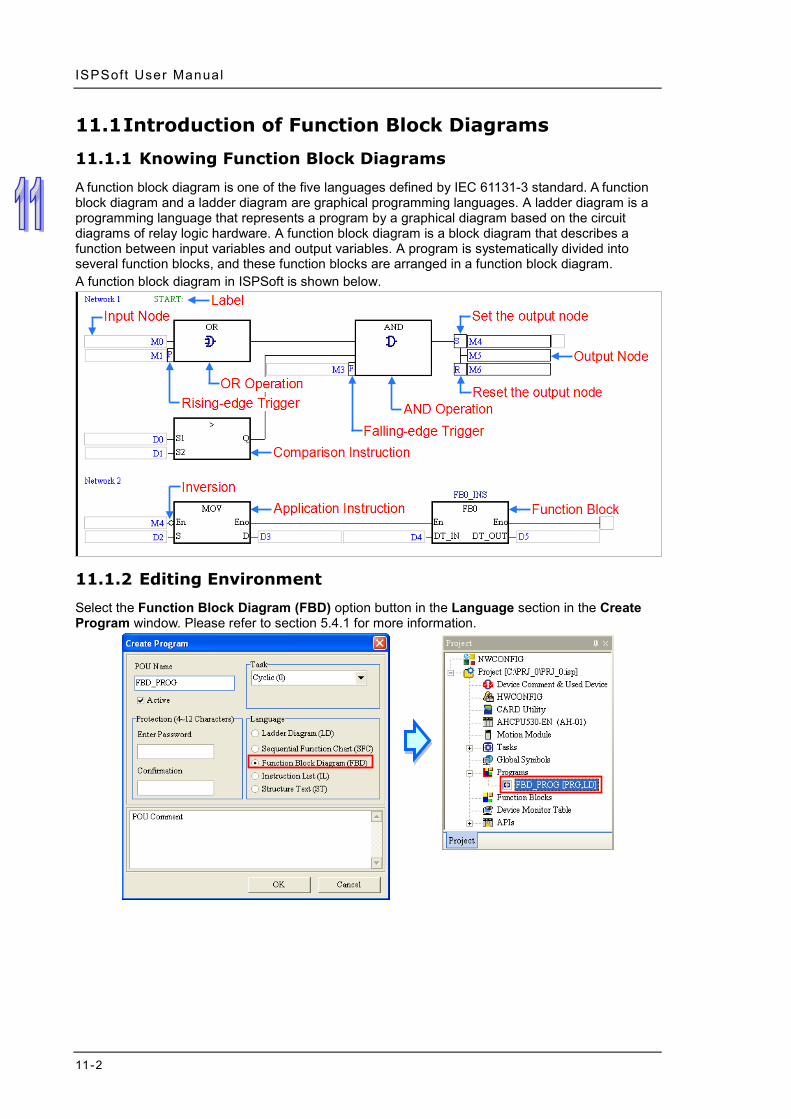
ISPSoft User Manual
11-2
11.1 Introduction of Function Block Diagrams
11.1.1 Knowing Function Block Diagrams
A function block diagram is one of the five languages defined by IEC 61131-3 standard. A function block diagram and a ladder diagram are graphical programming languages. A ladder diagram is a programming language that represents a program by a graphical diagram based on the circuit diagrams of relay logic hardware. A function block diagram is a block diagram that describes a function between input variables and output variables. A program is systematically divided into several function blocks, and these function blocks are arranged in a function block diagram. A function block diagram in ISPSoft is shown below.
11.1.2 Editing Environment
Select the Function Block Diagram (FBD) option button in the Language section in the Create Program window. Please refer to section 5.4.1 for more information.
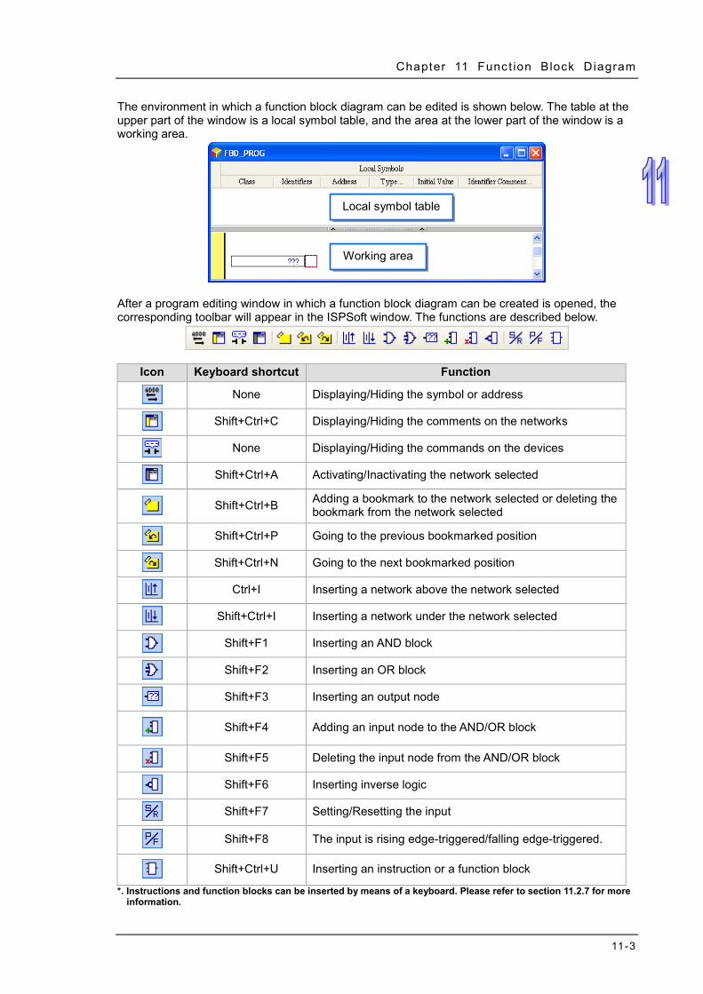
Chapter 11 Funct ion Block Diagram
11-3
The environment in which a function block diagram can be edited is shown below. The table at the upper part of the window is a local symbol table, and the area at the lower part of the window is a working area.
After a program editing window in which a function block diagram can be created is opened, the corresponding toolbar will appear in the ISPSoft window. The functions are described below.
Icon Keyboard shortcut Function
None Displaying/Hiding the symbol or address
Shift+Ctrl+C Displaying/Hiding the comments on the networks
None Displaying/Hiding the commands on the devices
Shift+Ctrl+A Activating/Inactivating the network selected
Shift+Ctrl+B Adding a bookmark to the network selected or deleting the bookmark from the network selected
Shift+Ctrl+P Going to the previous bookmarked position
Shift+Ctrl+N Going to the next bookmarked position
Ctrl+I Inserting a network above the network selected
Shift+Ctrl+I Inserting a network under the network selected
Shift+F1 Inserting an AND block
Shift+F2 Inserting an OR block
Shift+F3 Inserting an output node
Shift+F4 Adding an input node to the AND/OR block
Shift+F5 Deleting the input node from the AND/OR block
Shift+F6 Inserting inverse logic
Shift+F7 Setting/Resetting the input
Shift+F8 The input is rising edge-triggered/falling edge-triggered.
Shift+Ctrl+U Inserting an instruction or a function block
*. Instructions and function blocks can be inserted by means of a keyboard. Please refer to section 11.2.7 for more information.
Local symbol table
Working area

ISPSoft User Manual
11-4
11.1.3 Networks in a Function Block Diagram
A function block diagram consists of networks. Every network is an independent program. Besides, there is no limit on the number of objects which can be inserted in a network in ISPSoft. Network numbers are marked on the networks in a ladder diagram. The color at the left side of a network indicates the state of the network. A network can be activated or inactivated, and a network can be selected or unselected. Users can select colors which will be shown at the left sides of the networks in a ladder diagram in the Options window in ISPSoft. Please refer to section 2.3.1 for more information.
After a new window in which a ladder diagram will be created is opened, the system will insert a blank network in the window. If users want to add a network, they can select a network, and click
on the toolbar. The network added will be under the network selected.
If users click on the toolbar, a blank network will be put above the network selected.
The network is unselected and inactivated.
The network is selected and inactivated.
The network is unselected and activated.
The network is selected and activated.

Chapter 11 Funct ion Block Diagram
11-5
11.1.4 Selecting Objects
The red frame in the working area indicates the objects which are edited. It also indicates the objects which are selected. If users want to edit he program in the figure below, they can only select the positions marked with red frames. Besides, the functions which can be used vary with the position selected. The objects which are copied/cut/pasted/deleted depend on the position selected. The positions which are marked with red frames in the figure are described below.
The input node at the right side of this position is selected. M0 in the figure is selected.
The block before this position is selected.
All the blocks before this position are selected.
The output node at the right side of this position is selected. M1 in the figure is selected.
The whole network is selected.
The block is selected.
The block before this position is selected.
The output nodes under this position are selected.
The output node at the right side of this position is selected.
The block before this position is selected. If users want to select several networks, they can hold down Ctrl on the keyboard while they click the networks. The users can also select a range of networks by pressing Shift on the keyboard, clicking the first network within the range, and the last network within the range.

ISPSoft User Manual
11-6
11.2 Creating a Function Block Diagram in ISPSoft A basic function block diagram and its equivalent ladder diagram are shown below. The graphical representations in a function block diagram will be described in the following sections. Function block diagram
Equivalent ladder diagram
11.2.1 Input Nodes and Output Nodes
The devices and the symbols in a function block diagram are represented by nodes. An input node and the corresponding output node must conform to the rules listed below. (a) One node represents an M/S/T/C/HC device, and the other node represents a symbol whose
data type is BOOL/STEP/TIMER/COUNTER. (The device assigned to the node which represents a symbol is a bit device.)
(b) One node represents a D/L device, and the other node represents a symbol whose data type is

Chapter 11 Funct ion Block Diagram
11-7
not BOOL/STEP/REAL/STRING. (c) One node represents a T/C device, and the other node represents a D/L device or a symbol
whose data type is WORD/INT/TIMER/COUNTER. (d) One node represents a D/L/HC device, or a symbol whose data type is COUNTER, and to
which a HC device is assigned. The other node represents a symbol whose data type is DWORD/DINT.
(e) One node represents a symbol whose data type is WORD/DWORD/LWORD, and the other node represents a symbol whose data type is INT/DINT/LINT. The data length of the output node must be larger than or equal to the data length of the input node.
(f) Both nodes represent symbols whose data types are REAL/LREAL/STRING. The data lengths of the nodes must be the same.
(g) If an input node has multiple output nodes, the output nodes must conform to the rules listed above. 32 output nodes at most form a group. After users add an output node rightward, they can create another group of output nodes.
Graphical representation
Example
Example 1: The state of the contact M0 is sent to M1.
Example 2: The data in D0 is sent to D1.
Example 3: There are three groups of output nodes. The first group begins with M100, the second
group begins with M200, and the third group begins with M300. 32 output nodes at most form a group. After users add an output node rightward, they can create another group of output nodes. There is no limit on the number of output nodes which can be added rightward.
Example 4: Some incorrect examples are listed below.
Incorrect example Description
The data type of the input node must not be different from the data type of the output node.
The data length of the output node must not be less than the data length of the input node.
The value of a symbol whose data type is REAL can not be sent to a D device.

ISPSoft User Manual
11-8
Incorrect example Description
If the input node represents a symbol whose data type is REAL, the output node must represent a symbol whose data type is REAL. If the input node represents a symbol whose data type is LREAL, the output node must represent a symbol whose data type is LREAL.
The data length of the input node representing a symbol whose data type is STRING and the data length of the output node representing a symbol whose data type is STRING must be the same.
The value of a symbol whose data type is TIMER can not be sent to a symbol whose data type is DWORD, but can be sent to a symbol whose data type is WORD.
The value in a HC device can not be sent to a symbol whose data type is WORD, but can be sent to a symbol whose data type is DWORD.
The multiple output nodes must conform to the rules listed above. The example is incorrect because the data length of the output node representing a symbol whose data type is INT is less than the data length of the input node.
Inserting an output node
(1) Select a position into which an output node will be inserted in the working area. Users are allowed to insert output nodes into the positions marked with red frames in the figure below.
(2) In addition to the structure in the figure above, users may be allowed to insert an output node
into another structure. If users are allowed to insert an output node into the position selected, on the toolbar can be clicked. After is clicked, an output node will be inserted.

Chapter 11 Funct ion Block Diagram
11-9
An output node can be inserted in the following structures.
Inserting an output node into an input pin of an AND/OR block
Before
After
Inserting an output node into the output pin of an AND/OR block
Before
After
Adding an output node downward
Before
After
Adding an output node rightward
Before
After
*. Users are not allowed to insert output nodes into the output pins of a function block/an applied instruction to which operands are assigned.

ISPSoft User Manual
11-10
11.2.2 Using Devices, Symbols, and Constants in a Function Block Diagram
Before users edit a node or an operand of an instruction, they have to click the node or the operand.
Click in the box, and then select a symbol on the drop-down list. If a symbol whose data type is ARRAY is declared, the elements in the array will be on the drop-down list. Ary[…] in the figure below are elements.
The users can type a device name or a symbol in the box. If they type a symbol which is not declared, the Add Symbol window will appear after they press Enter on the keyboard. (Please refer to section 2.3.1 for more information about declaring a symbol.)
After users click a network and press Enter on the keyboard, they can edit a box. The users can edit the next box in the network after they press Enter on the keyboard. Besides, the next network will be selected after the users press Tab on the keyboard. The users can edit a box with the keyboard. If the users have declared symbols, they can press Page Down on the keyboard when they edit a box. The users can select a symbol by the up/down key on the keyboard. After the editing is complete, the users can press Enter on the keyboard to jump to the next box. If the users want to end the editing, they can press Esc on the keyboard. Additional remark (a) If users want to use constants in a function block diagram in ISPSoft, the constants must be
represented in the following ways. Decimal value: 23456 (A value which is not preceded by any mark will be regarded as a
decimal value.) Hexadecimal value: 16#5BA0 (A value is preceded by 16#.) Octal value: 8#55640 (A value is preceded by 8#.) Binary value: 2#101101110100000 (A value is preceded by 2#.) String: “XYZ” (Characters are put in double quotes.) Boolean value:
AH500: SM400 (normally-open contact), or SM401 (normally-closed contact) is used. DVP: M1000 (normally-open contact), or M1001 (normally-closed contact) is used.
(b) If users want to use a symbol whose data type is ARRAY, the expression format is Identifier[Index]. Generally speaking, an index is a decimal constant. The indexes in a function block diagram can not be symbols. The minimum index value for a symbol whose data type is ARRAY must be 0, and the maximum index value for a symbol whose data type is ARRAY can not be larger than the number of elements in the array.

Chapter 11 Funct ion Block Diagram
11-11
11.2.3 AND Block and OR Block
Contacts in a function block diagram can be connected in series/parallel by means of an AND/OR block. The input nodes and the output nodes of an AND/OR block must represent Boolean devices or symbols whose data types are BOOL. An AND/OR block have 32 input nodes and 32 output nodes at most. Besides, an AND/OR block has at least one output node, or is connected to the next object. Graphical representation
Example
Example 1: The contacts M0, M1, and M2 are assigned to the OR block, and the result of the operation is sent to M3. In other words, after M0, M1, and M2 are connected in parallel, the coil M3 will be driven if M0, M1, or M2 is ON.
Example 2: The contacts M0, M1, and M2 are assigned to the AND block, and the result of the
operation is sent to M3. In other words, after M0, M1, and M2 are connected in series, the coil M3 will be driven if M0, M1, and M2 are ON.
Example 3: The use of an AND block and an OR block in a function block diagram is equivalent to
the use of a serial connection and a parallel connection in a ladder diagram.
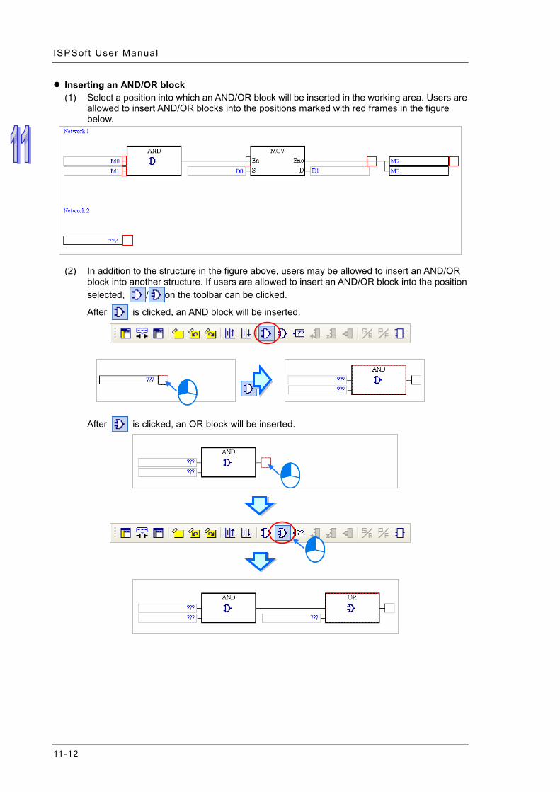
ISPSoft User Manual
11-12
Inserting an AND/OR block (1) Select a position into which an AND/OR block will be inserted in the working area. Users are
allowed to insert AND/OR blocks into the positions marked with red frames in the figure below.
(2) In addition to the structure in the figure above, users may be allowed to insert an AND/OR
block into another structure. If users are allowed to insert an AND/OR block into the position selected, / on the toolbar can be clicked.
After is clicked, an AND block will be inserted.
After is clicked, an OR block will be inserted.

Chapter 11 Funct ion Block Diagram
11-13
Adding an input node to an AND/OR block Select an input node of an AND/OR block, and then click on the toolbar. After is clicked, a node will be added to the bottom of the input node selected. If the input node selected is the topmost input node of an AND/OR block, e.g. M0 in the figure below, users can not add an input node.
If an AND/OR block is selected, an input node will be added to the bottom of the bottommost input node of the block after is clicked.
Deleting an input node from an AND/OR block
Select an input node which will be deleted from an AND/OR block, and then click on the toolbar. After is clicked, the input node will be deleted. Users have to pay attention to the following two points when they delete an input node. (a) The topmost input node of an AND/OR block, e.g. M0 in the figure below, can not be deleted. (b) If an AND/OR block has only two input nodes, neither of the input nodes can not be deleted.
11.2.4 Inverse Logic
Users can insert inverse logic into a Boolean position in a function block diagram, e.g. an input node which represents a Boolean device or a symbol whose data type is BOOL, an output node which represents a Boolean device or a symbol whose data type is BOOL, the En pin of a function block, or the En pint of an applied instruction. However, users have to notice that they are not allowed to insert inverse logic into the pins of a function block/an applied instruction to which operands are assigned. Graphical representation
Example Example 1: The state of M0 is inverted, and the inversion result is sent to M1. Likewise, the coil

ISPSoft User Manual
11-14
M1 will be driven if the normally-closed M0 is OFF.
Example 2: The inverse logic inserted into the output node indicates that the result of the
operation is inverted. The inversion result is sent to M3.
Example 3: If M0 is ON, the function block BLACK will be executed. If M0 is OFF, the function
block WHITE will be executed.
Example 4: The figure below is an incorrect example. Inverse logic can not be inserted into a
node which does not represent a Boolean device or a symbol whose data type is BOOL.
Inserting inverse logic
(1) Select a position into which inverse logic will be inserted in the working area. Users are allowed to insert inverse logic into the positions marked with red frames in the figure below. Although the operand assigned to the output pin of the instruction CMP is a Boolean operand, inverse logic can not be inserted into the output pin of CMP. Besides, inverse logic can not be inserted into a position which does not have an output node, and a position which is not connected to an object. For example, inverse logic can not be inserted into the input node in network 3.
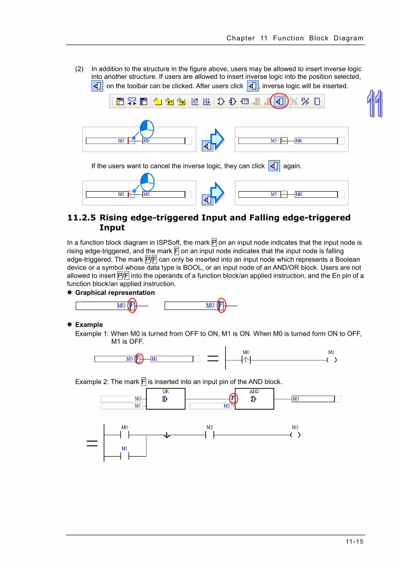
Chapter 11 Funct ion Block Diagram
11-15
(2) In addition to the structure in the figure above, users may be allowed to insert inverse logic
into another structure. If users are allowed to insert inverse logic into the position selected, on the toolbar can be clicked. After users click , inverse logic will be inserted.
If the users want to cancel the inverse logic, they can click again.
11.2.5 Rising edge-triggered Input and Falling edge-triggered Input
In a function block diagram in ISPSoft, the mark P on an input node indicates that the input node is rising edge-triggered, and the mark F on an input node indicates that the input node is falling edge-triggered. The mark P/F can only be inserted into an input node which represents a Boolean device or a symbol whose data type is BOOL, or an input node of an AND/OR block. Users are not allowed to insert P/F into the operands of a function block/an applied instruction, and the En pin of a function block/an applied instruction. Graphical representation
Example Example 1: When M0 is turned from OFF to ON, M1 is ON. When M0 is turned form ON to OFF,
M1 is OFF.
Example 2: The mark F is inserted into an input pin of the AND block.

ISPSoft User Manual
11-16
Example 3: The En pin of the first applied instruction is connected to the input node representing M0, and therefore the mark P can be inserted into in the input node representing M0. However, the mark P/F can not be inserted into the En pin of the second applied instruction.
Example 4: The figure below is an incorrect example. The mark F can not be inserted into an
input node which does not represent a Boolean device or a symbol whose data type is BOOL.
Inserting the mark P/F
(1) Select a position into which the mark P/F will be inserted in the working area. Users are allowed to insert the mark P/F into the positions marked with red frames in the figure below. Although the operand assigned to the input pin of the function block FB0 is a Boolean operand, the mark P/F can not be inserted into the input pin of FB0. Besides, P/F can not be inserted into a position which does not have an output node, and a position which is not connected to an object. For example, the mark P/F can not be inserted into the input node in network 3.

Chapter 11 Funct ion Block Diagram
11-17
(2) In addition to the structure in the figure above, users may be allowed to insert the mark P/F into another structure. If users are allowed to insert the mark P/F into the position selected,
on the toolbar can be clicked. After users click , the mark P will be inserted. If the users click again, the mark F will be inserted.
11.2.6 Setting an Output and Resetting an Output
In a function block diagram in ISPSoft, the mark S on an output node indicates that the output node is set to ON, and the mark R on an input node indicates that the output node is reset to OFF. Users are not allowed to insert S/R into the operands of a function block/an applied instruction. Graphical representation
Example
Example 1: If M0 is ON, M1 will be reset to OFF.
Example 2: In the figure below, the mark S is inserted into the output node representing M3, and
the mark R is inserted into the output node representing M4.

ISPSoft User Manual
11-18
Example 3: If M0 or M1 is ON, M2 will be set to ON. If M0 or M1 is ON, and M3 is ON, M4 will be reset to OFF.
Example 4: The figure below is an incorrect example. The mark S can not be inserted into an
output node which does not represent a Boolean device or a symbol whose data type is BOOL.
Inserting the mark S/R
(1) Select a position into which the mark S/R will be inserted in the working area. Users are allowed to insert the mark S/R into the positions marked with red frames in the figure below. Although the operand assigned to the output pin of the applied instruction CMP is a Boolean operand, the mark S/R can not be inserted into the output pin of CMP.

Chapter 11 Funct ion Block Diagram
11-19
(2) In addition to the structure in the figure above, users may be allowed to insert the mark S/R into another structure. If users are allowed to insert the mark S/R into the position selected,
on the toolbar can be clicked. After users click , the mark S will be inserted. If the users click again, the mark R will be inserted.
11.2.7 Applied Instruction, Comparison Contact, and Function Block
In a function block diagram in ISPSoft, the applied instructions, the comparison contacts, and the function blocks are represented by blocks. Besides, users can type function block instances in the boxes above the function blocks. If the logic state connected to the En pin of a block representing an applied instruction or a function block is ON, the applied instruction or the function block will be executed. A function block diagram is flexible in that users can put a logical operation, e.g. inverse logic or an AND/OR block, between two function blocks, between two applied instructions, or between a function block and an applied instruction in a network. Graphical representation

ISPSoft User Manual
11-20
Example Example 1: The En pin of a block representing an applied instruction in a function block diagram
can be connected to anther instruction or object.
Example 2: In a function block diagram, no object can precede a comparison contact, but the
output pin of the comparison contact can connect to an input pin of an AND/OR block, an output node, the En pin of a block representing a function block, or the En pin of a block representing an applied instruction.
*. Please refer to chapter 7 for more information about function blocks.

Chapter 11 Funct ion Block Diagram
11-21
Inserting an applied instruction, a comparison contact, or a function block (1) Select a position into which an applied instruction, a comparison contact, or a function block
will be inserted in the working area. In the figure below, users are allowed to insert applied instructions and function blocks into the positions marked with red frames, and comparison contacts into the positions marked with green triangles.
(2) There are three ways to insert an applied instruction, a comparison contact, or a function
block in a function block diagram. Method 1
Unfold the APIs section or the Function Blocks section in the project management area, and find the item which will be inserted. Select the item, and drag it to the position in which it will be inserted.

ISPSoft User Manual
11-22
Function block definitions can be dragged, but function block instances can not be dragged.
Method 2
Click the position into which an applied instruction, a comparison contact, or a function block will be inserted, click on the toolbar, select the item which will be inserted in the API/FB window, and click Insert.
Users can select the All Types option button, the Comparison Instruction option
button, the API option button, or the Function Block option button.
If users select the API option button in the Type Class section, they have to select an instruction type in the Classification box.
Users can select an applied instruction, a comparison contact, or a function block here.
If users unselect the Auto Close checkbox, they can insert instructions or function blocks continuously.
Method 3 Click the position into which an applied instruction, a comparison contact, or a function block will be inserted, and type the applied instruction, the comparison contact instruction, or the function block definition. As soon as the applied instruction, the comparison contact instruction, or the function block definition is typed, a box which can

Chapter 11 Funct ion Block Diagram
11-23
be edited appears. After the typing of the applied instruction, the comparison contact instruction, or the function block definition is complete, users can press Enter on the keyboard or click OK at the right side of the box. (The applied instruction, the comparison contact instruction, and the function block definition are case-insensitive.)
If users want to insert a function block, they have to type the function block definition, and they can not type the operands specifed in the function block. If users want to insert a comparison contact or an applied instruction, they have to type the comparison contact instruciton or the applied instruction, and they can type the operands specified in the comparison contact instruciton or the applied instruction. The users do not have to type all the operands specified in the comparison contact instruciton or the applied instruction. The system will assign the operands typed to the corresponding boxes, and ??? will appear in the boxes where there are no operands. Besides, if the operands typed include a symbol which is not declared, the Add Symbol window will appear after the users press Enter on the keyboard. Please refer to programming manuals for more information about instructions.
(3) After an applied instruction, a comparison contact, or a function block is inserted
successfully, users have to type operands.
*. If the Auto-leading ‘Add Symbol’ Dialog checkbox in the Options window is selected, the Add Symbol window will
appear automatically after users type a symbol which is not declared. Please refer to section 2.3.1 for more information.
11.2.8 Putting a Label
If users want to use a jump instruction, they have to put a label on the network to which the execution of the program jumps. A label is put at the right side of a network number. Besides, if the project created is a project for a DVP series PLC, the label put on a network must be a P device. The P devices in an AH/AS series CPU module are automatically assigned by the system, and can not be used by users. If the project created is a project for an AH/AS series CPU module, the label symbol users type must be a unique label. The label symbol users type in a project for an AH/AS series CPU module does not need to be declared in a symbol table. Please refer to user manuals for

ISPSoft User Manual
11-24
more information about P devices.
If users want to specify a label in an instruction, they do not have to type a colon in front of the label.
The steps of putting a label are as follows. (1) Click the right side of the network number at which a label will be put.
(2) If the project created is a project for a DVP series PLC, users have to type a P device number.
If the project created is a project for an AH/AS series CPU module, users have to type a label symbol. Press Enter on the keyboard after a P device number or a label symbol is typed. The system will automatically put a colon at the right side of the label.
11.2.9 Comments and Hints
Users can make comments on the networks in a function block diagram in ISPSoft. They can type comments under the network numbers in a function block diagram in ISPSoft.
Editing the comment on a network (1) After users click on the toolbar, the comments on the networks will be displayed. If the
users click on the toolbar again, the comments on the networks will be hidden.

Chapter 11 Funct ion Block Diagram
11-25
(2) After the users click the position under a network number, a box will appear.
(3) Type a comment in the box. If the users want to start a new line of text at a specific point,
they can press Shift+Enter on the keyboard. Press Enter on the keyboard after the editing is complete.
Hints related to the devices and the symbols in a function block diagram
In a function block diagram, the comments on the devices and the comments on the symbols are not displayed. If users want to view the comment on a device or a symbol, they have to make sure that on the toolbar is clicked, and move the mouse cursor to the device or the symbol. After the mouse cursor stays at the device or the symbol for a while, the hints related to the device or the symbol will appear. The users can select hints in the Options window in ISPSoft. Please refer to section 2.3.1 for more information. If the users want to hide the hints, they can click again.

ISPSoft User Manual
11-26
Besides, owing to fact that the devices and the symbols are different objects in ISPSoft, the hints related to the devices are different from the hints related to the symbols.
Additional remark Users can make a comment on a device by means of the comment management tool provided by ISPSoft. Please refer to section 16.2 for more information.
11.2.10 Symbol Mode and Address Mode
If a device address is assigned to a symbol declared in a function block diagram, users can change the mode in which the symbol is displayed by means of clicking on the toolbar. However, the symbols to which no devices are assigned and the devices to which no symbols are assigned will remain unchanged after on the toolbar is clicked.
If on the toolbar is not clicked, the identifiers of the symbols to which devices are assigned will be displayed, and the hints which appear will be the hints related to the symbols.

Chapter 11 Funct ion Block Diagram
11-27
If on the toolbar is clicked, the devices to which symbols are assigned will be displayed, and the hints which appear will be the hints related to the devices.
11.2.11 Bookmark
After networks are bookmarked, users can find or go to the networks easily. (1) After users click on the toolbar, a bookmark will be inserted in the network selected. If the
users want to delete the bookmark, they can select the network, and click on the toolbar again.

ISPSoft User Manual
11-28
(2) If there are bookmarks in a program, users can go to the next network which is bookmarked by clicking on the toolbar, and go to the previous network which is bookmarked by clicking
on the toolbar.
Additional remark After users point to Bookmarks on the Edit menu, they can select Toggle Bookmark, Goto the Next Bookmark, Goto the Previous Bookmark, or Remove All Bookmarks. If the users click Remove All Bookmarks, all the bookmarks in the present program editing window will be deleted.
11.2.12 Activating/Inactivating a Network
If a network is inactivated, the compiling of the program will skip the network. When users test or debug a program, they can inactivate some part of the program temporarily by means of this function. The color at the left side of a network indicates whether the network is activated or inactivated. Users can select colors which will be shown at the left sides of the networks in a ladder diagram in the Options window in ISPSoft. Please refer to section 2.3.1 for more information.
The network is inactivated.
The network is activated.

Chapter 11 Funct ion Block Diagram
11-29
If users want to activate or inactivate a network, they have to select the network first. Users can select several networks simultaneously.
Right-click the network selected, and click Activate/InactivateNetwork on the context menu. The network selected will be activated/inactivated. Users can also activate/inactivate the network selected by clicking Activate/InactivateNetwork on the Edit menu, or by clicking on the toolbar.
If users want to activate all the networks which are inactivated in the present program editing window, they can click Activate All Networks on the Edit menu.

ISPSoft User Manual
11-30
MEMO

12-1
Chapter 12 Instruction List Table of Contents 12.1 Introduction of Instruction Lists ............................................................12-2
12.1.1 Structure of an Instruction List ......................................................12-2 12.1.2 Calling a Function Block ...............................................................12-4 12.1.3 Important Points About Instruction Lists .......................................12-5
12.2 Creating an Instruction List in ISPSoft .................................................12-6 12.2.1 Editing Environment ......................................................................12-6 12.2.2 Creating an Instruction List ...........................................................12-7 12.2.3 Inserting Applied Instructions and Function Blocks.......................12-8 12.2.4 Bookmark .....................................................................................12-9
12.2.4.1 Adding Bookmarks ..............................................................12-10 12.2.4.2 Removing Bookmarks ......................................................... 12-11 12.2.4.3 Going to a Bookmark ...........................................................12-12

ISPSoft User Manual
12-2
12.1 Introduction of Instruction Lists An instruction list is one of the five languages supported by the IEC 61131-3 standard. It is a low level language and resembles an assembly language. In earlier times, users entered control instructions into a PLC through a programming panel, and the programming language used was an instruction list.
12.1.1 Structure of an Instruction List
An instruction list is composed of statements. Every statement represents an action. A task which can be accomplished by a complete ladder diagram can be accomplished by an instruction list composed of many instructions. An example of an instruction list is shown below. There are five lines of program code. The ladder diagram corresponding to the instruction list is shown at the right side of the instruction list.
LD M0: Loading the state of M0
OR M1: The logical OR operation is performed on M1.
AND M2: The logical AND operation is performed on M2.
OUT M3: M3 The result of the operation is sent to M3.
(*Note*): It is a comment on the program. When the program is compiled, this line is skipped automatically.
No action
Every statement on an instruction list is composed of an operator and operands. An operator is a function representing an operation, and an operand is the object of an operation. An operand can be a device, a symbol, or a constant. Besides, the operands for an operator are separated by spaces.

Chapter 12 Ins truc t ion L ist
12-3
The operator MOV in the example below denotes that an action of transferring data will be executed. The operands D0 and D1 are the source device and the destination device which take part in the transfer.
On an instruction list, the words between (* and *) are regarded as comments. When a program is compiled, the system automatically skips the words between (* and *). Besides, as long as the structure of an instruction list is not destroyed, comments can be put anywhere on the instruction list. However, users have to be careful about the readability of the instruction list. The comments in the example below are legal.
Instructions are divided into basic instructions and advanced instructions. Please refer to programming manuals for more information about the usage of instructions. If users want to check the usage of an instruction, they can click PLC Instruction and Special Registers Reference on the Help menu.
Besides, if users press F1 after they click an instruction, the usage of the instruction will be displayed in the window which appears.

ISPSoft User Manual
12-4
12.1.2 Calling a Function Block
The important points about calling a function block on an instruction list are listed below.
CAL, the function block instance and the left parenthesis must be in the same line while the other
parts can be in different lines. The input/output pins of the function block and the corresponding operands must be put in
parentheses. A pin and the corresponding operand form a group. The groups are separated by commas. The data types of the operands are specified in the function block definition.
The function block after CAL is a function block instance rather than a function block definition, that is, the symbol after CAL is a symbol whose data type is a function block. Please refer to chapter 7 for more information about function block definitions and function block instances.
The assignment mark for an input pin is :=, and the assignment mark for an output pin is =>. The pins and the operands are arranged according to the definition of the function block. The
arrangement can not be changed. The En pin and the Eno pin are excluded. The input pins are listed above all the output pins. A pin of the VAR_IN_OUT class is an input pin. Please refer to the ladder diagram and the instruction list below for more information.
The state of the En pin of the function block is not specified in the instruction CAL. When the
instruction is executed, the result of the logical operation before the instruction determines whether the function block will be enabled.

Chapter 12 Ins truc t ion L ist
12-5
12.1.3 Important Points About Instruction Lists
Every line on an instruction list is regarded as an instruction except the instruction CAL, and therefore an operator and the operands for the operator can not be in different lines. If an operator and the operands for the operator are in two lines, these two lines will be regarded as two incomplete instructions. Besides, no spaces can be inserted into the instruction names, the function block names, and the operand names on an instruction list. Otherwise, the instructions, the function blocks, and the operands will not be recognized if the program is compiled.
As long as the format of an instruction is not destroyed, leaving blank spaces and starting new
lines are allowed. Fullwidth characters and halfwidth characters in ISPSoft are regarded as different characters.
Please avoid using fullwidth characters lest they should be identified incorrectly. Instruction lists are case-insensitive. “OUT” and “Out” are considered to be the equivalents of
“out”. If users want to use constants in a program created by means of an instruction list in ISPSoft, the
constants must be represented in the following ways. Decimal value: 23456 (A value which is not preceded by any mark will be regarded as a
decimal value.) Hexadecimal value: 16#5BA0 (A value is preceded by 16#.) Octal value: 8#55640 (A value is preceded by 8#.) Binary value: 2#101101110100000 (A value is preceded by 2#.) String: “XYZ” (Characters are put in double quotes.) Boolean value:
AH500: SM400 (normally-open contact), or SM401 (normally-closed contact) is used. DVP: M1000 (normally-open contact), or M1001 (normally-closed contact) is used.
If users want to use a symbol whose data type is ARRAY, the expression format is Identifier[Index]. Generally speaking, an index is a decimal constant. The indexes on an instruction list can not be symbols. The minimum index value for a symbol whose data type is ARRAY must be 0, and the maximum index value for a symbol whose data type is ARRAY can not be larger than the number of elements in the array.
If a function block or an applied instruction is not preceded by the instruction LD or a logical operation, an error will occur if the program is compiled.
Although there is no limit on the number of lines, users still have to consider the capacity of the
memory in the PLC. The sections of an instruction list in ISPSoft can be copied/cut/pasted. Users can copy the text in
a file edited with a text editor into an instruction list in ISPSoft.
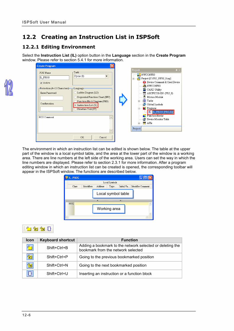
ISPSoft User Manual
12-6
12.2 Creating an Instruction List in ISPSoft
12.2.1 Editing Environment
Select the Instruction List (IL) option button in the Language section in the Create Program window. Please refer to section 5.4.1 for more information.
The environment in which an instruction list can be edited is shown below. The table at the upper part of the window is a local symbol table, and the area at the lower part of the window is a working area. There are line numbers at the left side of the working area. Users can set the way in which the line numbers are displayed. Please refer to section 2.3.1 for more information. After a program editing window in which an instruction list can be created is opened, the corresponding toolbar will appear in the ISPSoft window. The functions are described below.
Icon Keyboard shortcut Function
Shift+Ctrl+B Adding a bookmark to the network selected or deleting the bookmark from the network selected
Shift+Ctrl+P Going to the previous bookmarked position
Shift+Ctrl+N Going to the next bookmarked position
Shift+Ctrl+U Inserting an instruction or a function block
Local symbol table
Working area

Chapter 12 Ins truc t ion L ist
12-7
12.2.2 Creating an Instruction List
The way in which an instruction list file is edited is similar to the way in which a text file is edited with a general text editor. If users want to create an instruction list, they can type or modify text in the working area. If the users want to start a new line of text at a specific point, they can press Enter on the keyboard.
If users want to select any amount of text, they can click where they want to begin the selection, hold down the left mouse button, and drag the pointer over the text that they want to select. The users can also click at the start of the selection, scroll to the end of the selection, and hold down Shift on the keyboard while they click where they want the selection to end.
If users type a symbol which has not been declared, they can click the symbol, click the right mouse button, and click Add Symbol on the context menu to open the Add Symbol window.

ISPSoft User Manual
12-8
12.2.3 Inserting Applied Instructions and Function Blocks
Users can insert an applied instruction or a function block in an instruction list in ISPSoft in one of the three ways described below. Method 1
An applied instruction or a function block is inserted according to the format of the applied instruction or the format of the function block.
Method 2
Unfold the APIs section or the Function Blocks section in the project management area, and find the item which will be inserted. Select the item, and drag it to the position in which it will be inserted.
After the applied instruction or the function block is inserted, users have to type the corresponding operands according to the format of the applied instruction or the format of the function block.
Function block definitions can be dragged, but function block instances can not be dragged.

Chapter 12 Ins truc t ion L ist
12-9
Method 3 Click the position in which an applied instruction or a function block will be inserted, click on the toolbar, select the item which will be inserted in the API/FB window, and click Insert.
Users can select the All Types option button, the Comparison Instruction option button, the API option button, or the Function Block option button.
If users select the API option button in the Type Class section, they have to select an instruction type in the Classification box.
Users can select an applied instruction, a comparison contact, or a function block here.
If users unselect the Auto Close checkbox, they can insert instructions or function blocks continuously.
After the applied instruction or the function block is inserted, users have to type the corresponding operands according to the format of the applied instruction or the format of the function block.
12.2.4 Bookmark
After lines are bookmarked, users can find or go to the lines easily. Users can add ten bookmarks at most to an instruction list.

ISPSoft User Manual
12-10
12.2.4.1 Adding Bookmarks
Method 1 If users want to add a bookmark to a line, they can select the line, click the right mouse button, click Bookmarks on the context menu, and select a bookmark number. If the bookmark number selected has been added to another line, the bookmark number will be moved to the line selected presently.
Method 2
If users want to add a bookmark to a line, they can click the line, and click on the toolbar. The users can also add a bookmark to a line by clicking the line, clicking the Edit menu, pointing to Bookmarks, and clicking Toggle Bookmark. The bookmarks added in this way are numbered in sequence. The users can not specify bookmark numbers.

Chapter 12 Ins truc t ion L ist
12-11
12.2.4.2 Removing Bookmarks
Method 1 If users want to remove the bookmark from a line, they can select the line, click the right mouse button, click Bookmarks on the context menu, and click the bookmark number corresponding to the bookmark added to the line. If the bookmark number clicked does not correspond to the bookmark added to the line, the bookmark number added to the line will become the bookmark number clicked. Besides, if the bookmark number clicked has been added to another line, the bookmark number will be moved to the line selected presently.
Method 2
If users want to remove the bookmark from a line, they can click the line, and click on the toolbar. The users can also remove the bookmark from a line by clicking the line, clicking the Edit menu, pointing to Bookmarks, and clicking Toggle Bookmark. If the users click the Edit menu, point to Bookmarks, and click Remove All Bookmarks, all the bookmarks in the present program editing window will be deleted.

ISPSoft User Manual
12-12
12.2.4.3 Going to a Bookmark
Method 1 Right-click the working area, point to Goto the Bookmark on the context menu, and click a bookmark number.
Method 2
If there are bookmarks in a program, users can go to the next line which is bookmarked by clicking on the toolbar, and go to the previous line which is bookmarked by clicking on the toolbar. The users can also go to the next/previous line which is bookmarked by clicking the Edit menu, pointing to Bookmarks, and clicking Goto the Next Bookmark/Goto the previous Bookmark.

13-1
Chapter 13 Structured Texts Table of Contents 13.1 Knowing Structured Texts ....................................................................13-2
13.1.1 Basic Structure of a Structured Text .............................................13-2 13.1.2 Statement .....................................................................................13-2 13.1.3 Expression ....................................................................................13-3 13.1.4 Operand and Operator ..................................................................13-4 13.1.5 Keyword and Comment ................................................................13-5 13.1.6 Using a Symbol Whose Data Type is ARRAY in a Structured Text …………………………………………………………………………..13-7 13.1.7 Important Points About Structured Texts ......................................13-7
13.2 Structure of a Statement ......................................................................13-8 13.2.1 Assignment Structure─:= ..............................................................13-8 13.2.2 Conditional Structure - IF ............................................................13-10 13.2.3 Conditional Structure─CASE ......................................................13-12 13.2.4 Loop Structure - REPEAT ...........................................................13-14 13.2.5 Loop Structure - WHILE ..............................................................13-15 13.2.6 Loop Structure - FOR .................................................................13-16 13.2.7 Applied Instruction Structure .......................................................13-17 13.2.8 Function Block Structure .............................................................13-18 13.2.9 Blank Statement .........................................................................13-19 13.2.10 RETURN Statement ...................................................................13-20 13.2.11 EXIT Statement ..........................................................................13-20
13.3 Creating a Structured Text in ISPSoft ................................................13-21 13.3.1 Editing Environment ....................................................................13-21 13.3.2 Creating a Structured Text ..........................................................13-22 13.3.3 Inserting Applied Instructions and Function Blocks.....................13-23 13.3.4 Bookmark ...................................................................................13-24
13.4 Example of a Structured Text ............................................................13-25 13.4.1 Explanation .................................................................................13-25 13.4.2 Planning Hardware .....................................................................13-25 13.4.3 Planning a Program ....................................................................13-25 13.4.4 Creating a Program ....................................................................13-26

ISPSoft User Manual
13-2
13.1 Knowing Structured Texts A structured text is a high level language that is syntactically resembles C or Pascal. It is composed of text. Compared with instruction lists, structured texts are more readable. A structured text is very flexible and intuitive for writing control algorithms. People who are trained in programming languages often find it the easiest language to use for programming control logic. Besides, structured texts provide a familiar programming environment for programmers who are familiar with the C language.
13.1.1 Basic Structure of a Structured Text
The structured text shown below is a basic structured text. It has the same function as the ladder diagram under it. The structure of the structured text is similar to the syntax of human language. A structured text is composed of statements.
The structure of the structured text above is shown below.
* In a structured text, “:=” means “to assign”, and “=” means “to be equal to”.
13.1.2 Statement
The statement is a basic unit. It represents a complete task which can be executed. A complete statement may not be represented by a single line, but it always ends with a semicolon.

Chapter 13 Struc tured Texts
13-3
A complete statement corresponds to a network in a ladder diagram. It represents a task. Take the sub-statement shown above for example. The value of the arithmetic expression D0* (D1+D2) is calculated, and the result of the operation is stored in D10. The arithmetic expression in the red frame in the figure below is not a legal statement. It is an expression. It is not a concrete task. It is like the ladder diagram shown below. The ladder diagram lacks an output operand. It is not a complete program which can be executed.
A structured text is composed of statements, and a statement is composed of elements. An example of a structured text is shown below. The complete statements in the structured text are in the red frames.
* In a structured text, “:=” means “to assign”, and “=” means “to be equal to”.
13.1.3 Expression
An expression is an important element of a statement. It represents a value. An expression can be an arithmetic expression, a constant, a symbol, or a device. Examples are listed below. M0 & M1 (Boolean value)
The logical operator & takes M0 and M1, and performs the logical & operation on M0 and M1. The result of the operation is a Boolean value.
M0 = FALSE (Boolean value) The expression is a conditional expression. If M0 is ON, the Boolean value is TRUE. If M0 is OFF, the Boolean value is TRUE.
M0 (Boolean value) If M0 is ON, the Boolean value is TRUE. If M0 is OFF, the Boolean value is FALSE.
D1 + D2 (Value) The value of the arithmetic expression D1+D2 is calculated.
D0 (Value) The value represented by the expression if the value stored in D0.
D2 = D0 + D1 (Boolean value) If the value of the arithmetic expression D0+D1 is equal to the value stored in D2, the Boolean value is TRUE. If the value of the arithmetic expression D0+D1 is not equal to the value stored in D2, the Boolean value is FALSE.

ISPSoft User Manual
13-4
D2 := D0 + D1; (Statement) This is a statement rather than an expression. The value of the arithmetic expression D0+D1 is calculated, and the result of the operation is stored in D2. This statement is composed of the expression D2 and the expression D0+D1.
Please refer to the following example. The program is mainly composed of two IF statements. When the first IF statement is executed, the system evaluates the expression M0. If M0 is ON, the value of the arithmetic expression D21+D22 will be calculated, and the result of the operation will be stored in D20. When the second IF statement is executed, the system judges whether the value of the arithmetic expression D0* (D1+D2) is equal to the value stored in D20. If the value of the arithmetic expression D0* (D1+D2) is equal to the value stored in D20, the Boolean value is TRUE, and the value of M1 is TRUE. If the value of the arithmetic expression D0* (D1+D2) is not equal to the value stored in D20, the value of M1 is FALSE.
13.1.4 Operand and Operator
Operands and operators are basic elements of an expression. An operand is the object of an operation, and an operator is a symbol or function representing an operation. For example, in the expression D0 + D1, D0 and D1 are operands, and + is an operator. An expression can be composed of operands and operators. It can also be composed of a single operand. The operands in an expression can be devices, symbols, or constants.
Rules of precedence affect which values form operands for which operators. If the operators in an expression share the same precedence, the order of the operation is carried out from left to right. The operands which can be used in a structured text in ISPSoft are listed below.

Chapter 13 Struc tured Texts
13-5
Symbol Function
Data format Example of an expression
Precedence Operand
Result of an operation
(Value of an expression)
Expression Value
( )
The parenthetical part of an expression is calculated first.
Unspecified Unspecified (D0 + 6)* 3 33 Highest
** Exponentiation Floating-point number
Floating-point number 2.0 ** 5.0 3.2E+1
- Negative sign Signed number
Signed number -(D0 + 3) -8
NOT Logical negation
Boolean value Boolean value NOT M0 TRUE
* Multiplication Any value Any value D0 * 3 15 / Division Any value Any value 15 / D0 3
MOD Remainder Integer Integer D0 MOD 3 2
+ , - Addition, subtraction Any value Any value D0 + 3 8
< , >,<=, >= Comparison Any value Boolean value D0 > 2 TRUE
=, <> Equal to, not equal to
Any value Boolean value
D0 <> 2 TRUE
Boolean value M0 = TRUE FALSE
AND, & Logical AND operation
Boolean value Boolean value M0 & M1 FALSE
XOR Logical
exclusive OR operation
Boolean value Boolean value M0 XOR M1 TRUE
OR Logical
inclusive OR operation
Boolean value Boolean value M0 OR M1 TRUE Lowest
*1. In the table above, the default value of M0 is FALSE, the default value of M1 is TRUE, and the default value of D0 is 5.
*2. The operands for an exponentiation operator must be constants or floating-point symbols, and must not be devices.
13.1.5 Keyword and Comment
In computer programming, a keyword is a word which has a special meaning to the programming language. For example, TRUE and FALSE in a program represent Boolean values, and the IF statements in the example above represent tasks which will be executed. Besides, applied instructions are regarded as keywords. In order to prevent a program from being compiled incorrectly, the words which are regarded as keywords in the program cannot be declared to be symbols. However, the words which are regarded as keywords in a program can be parts of the symbols in the program. For example, “FIFO” and “_IF” are allowed. In a structured text, the words between (* and *) are regarded as comments. When a program is compiled, the system automatically skips the words between (* and *) in the program. Besides, as long as the structure of a structured text is not destroyed, comments can be put anywhere in the structured text. However, users have to be careful about the readability of the structured text.
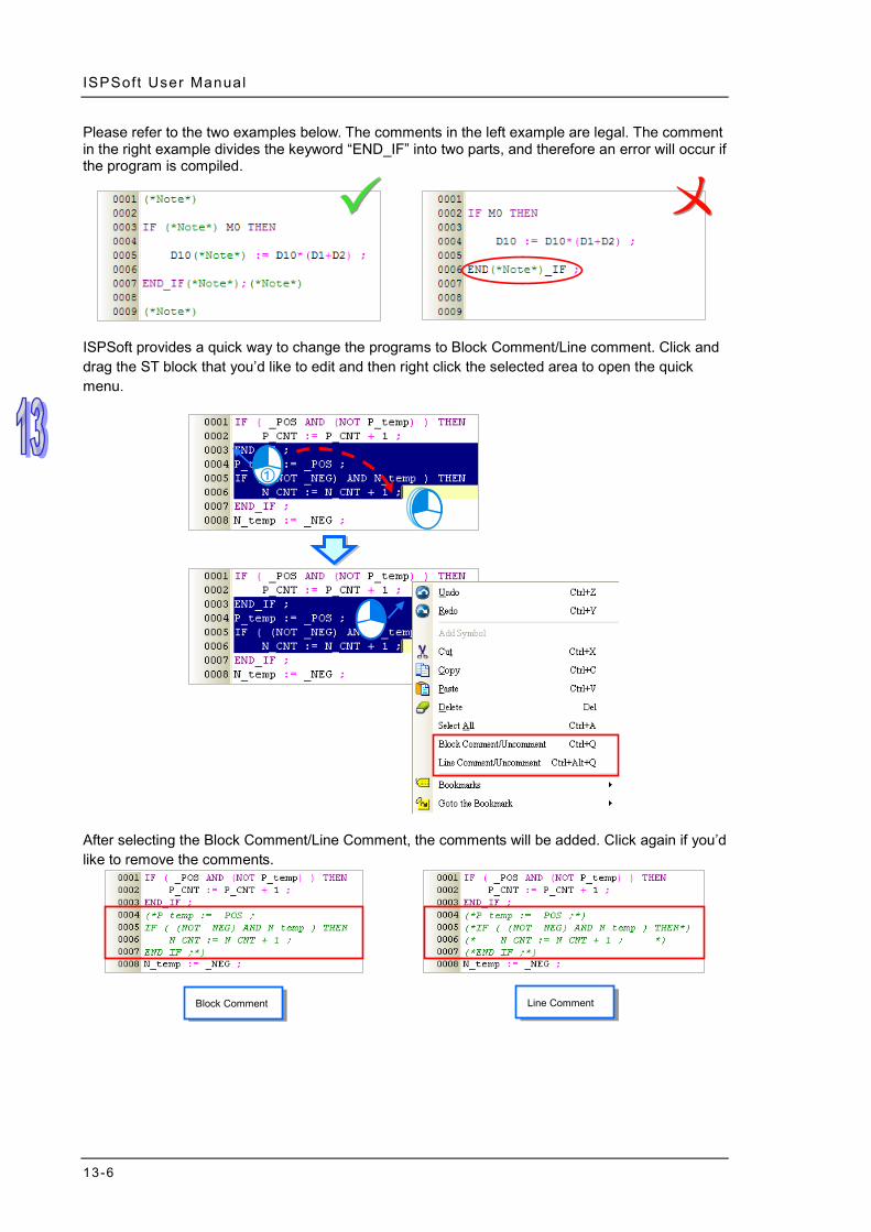
ISPSoft User Manual
13-6
Please refer to the two examples below. The comments in the left example are legal. The comment in the right example divides the keyword “END_IF” into two parts, and therefore an error will occur if the program is compiled.
ISPSoft provides a quick way to change the programs to Block Comment/Line comment. Click and drag the ST block that you’d like to edit and then right click the selected area to open the quick menu.
After selecting the Block Comment/Line Comment, the comments will be added. Click again if you’d like to remove the comments.
Block Comment Line Comment

Chapter 13 Struc tured Texts
13-7
13.1.6 Using a Symbol Whose Data Type is ARRAY in a Structured Text
If users want to use a symbol whose data type is ARRAY in a structured text, the expression format is Identifier[Index]. The index is a constant or a symbol. However, only the indexes in a project for an AH/AS series CPU module can be symbols. The minimum index value must be 0, whether the index is a constant or a symbol. The maximum index value cannot be larger than or equal to the number of elements in the array. For example, if the number of elements in an array is 10, the index value must be within the range between 0 and 9. Please refer to section 6.2.3 for more information.
Besides, users have to pay attention to the following points when they use a symbol whose data type is ARRAY. Users can only manipulate a single element in an array. A symbol which represents an array can
not be used as an operand. The arrays that ISPSoft supports are one-dimensional arrays but the structure from the Data Unit
Type can support up to three-dimensional arrays. This type of variables can be written as the image shown below. DO value is written in the pt1 [1,1,1] of the vardut. Refer to chapter 8 for more information.
If an index is a symbol, and the value of the symbol is not within a legal range, the PLC will
continue running and no error will occur. However, the data taking part in the operation may be incorrect.
If the index for a symbol is constant, the symbol can be modified by an index register. If the index for a symbol is a symbol, the symbol can not be modified by an index register. Please refer to section 6.1.5 for more information.
13.1.7 Important Points About Structured Texts
If the structure of the keywords or the statements in a structured text is destroyed, starting new lines and leaving blank spaces will be allowed.
In principle, fullwidth characters and halfwidth characters in ISPSoft are regarded as different characters. Please avoid using fullwidth characters lest they should be identified incorrectly.
Structured texts are case-insensitive. “IF” and “If” are considered to be the equivalents of “if”. (The C language is case-sensitive.)
If users want to use constants in a structured text in ISPSoft, the constants must be represented in the following ways. Decimal value: 23456 (A value which is not preceded by any mark will be regarded as a
decimal value.) Hexadecimal value: 16#5BA0 (A value is preceded by 16#.) Octal value: 8#55640 (A value is preceded by 8#.) Binary value: 2#101101110100000 (A value is preceded by 2#.) String: “XYZ” (Characters are put in double quotes.) Boolean value: TRUE or FALSE
In a structured text in ISPSoft, the data types of the operands in an expression must be the same. However, if the data type of one operand is INT and the data type of the other operand is WORD, the operands can take part in the operation. Likewise, if the data type of one operand is DINT and the data type of the other operand is DWORD, the operands can take part in the operation. If the

ISPSoft User Manual
13-8
data lengths of the operands in an expression are different, the operands can not take part in the operation.
If the data type of a symbol is WORD, DWORD, LWORD, INT, DINT, or LINT, the system regards
it as a signed integer during the operation. Although there is no limit on the number of lines, users still have to consider the capacity of the
memory in the PLC. The sections of a structured text in ISPSoft can be copied/cut/pasted. Users can copy the text in a
file edited with a text editor into a structured text in ISPSoft. The instructions that a structured text supports are as follows.
AH/AS series CPU module All the basic instructions are not supported. For example, LD, LDI, OUT, SET, RST, LD&, and etc are not supported. All the pulse instructions are not supported. For example, ROLP, RORP, BCDP, TRDP, and etc are not supported. The Four Arithmetic Operations instructions, the Logical Operation instructions, the Contact Type Logic Operation instructions, and the Structure Creation instructions are not supported. PLS, PLF, MOV, DMOV, DFMOV, $MOV, MC, MCR, CJ, JMP, GOEND, and etc are not supported.
13.2 Structure of a Statement
13.2.1 Assignment Structure─:=
Format
Description
The value represented by the expression at the right side of := is assigned to the device or the symbol at the left side of :=.
Rules and limits The expression at the right side of := can be a constant, a device, a symbol, or an arithmetic
expression. Only a device or a symbol can be at the left side of :=. The operands at both sides of := must conform to the rules listed below.
(a) One operand is an M/S/T/C/HC device, and the other operand is a symbol whose data type is BOOL/STEP/TIMER/COUNTER. (The device assigned to the operand which is a symbol is a bit device.)
(b) One operand is a D/L device, and the other operand is a symbol whose data type is not BOOL/STEP/REAL/STRING.
(c) One operand is a T/C device, and the other operand is a D/L device or a symbol whose data type is WORD/INT/TIMER/COUNTER.
(d) One operand is a D/L/HC device, or a symbol whose data type is COUNTER, and to which a HC device is assigned. The other operand is a symbol whose data type is DWORD/DINT.
(e) One operand is a symbol whose data type is WORD/DWORD/LWORD, and the other operand is a symbol whose data type is INT/DINT/LINT. The data length of the operand at the left side of := must be larger than or equal to the data length of the operand at the right side of :=.
(f) Both operands are symbols whose data types are REAL/LREAL/STRING. The data lengths of the operands must be the same.

Chapter 13 Struc tured Texts
13-9
Example Example 1: The value of M0 is assigned to the symbol OUT_0.
Example 2: M0 is set to ON.
Example 3: The value in D2 is added to the value in D1. The sum is stored in D0.
Example 4: 3 is assigned to the symbol DATA.
Example 5: The system judges whether the value of the arithmetic expression 3*2+6* (5+3) is equal to the value stored in D0. The judgement result is sent to M0.
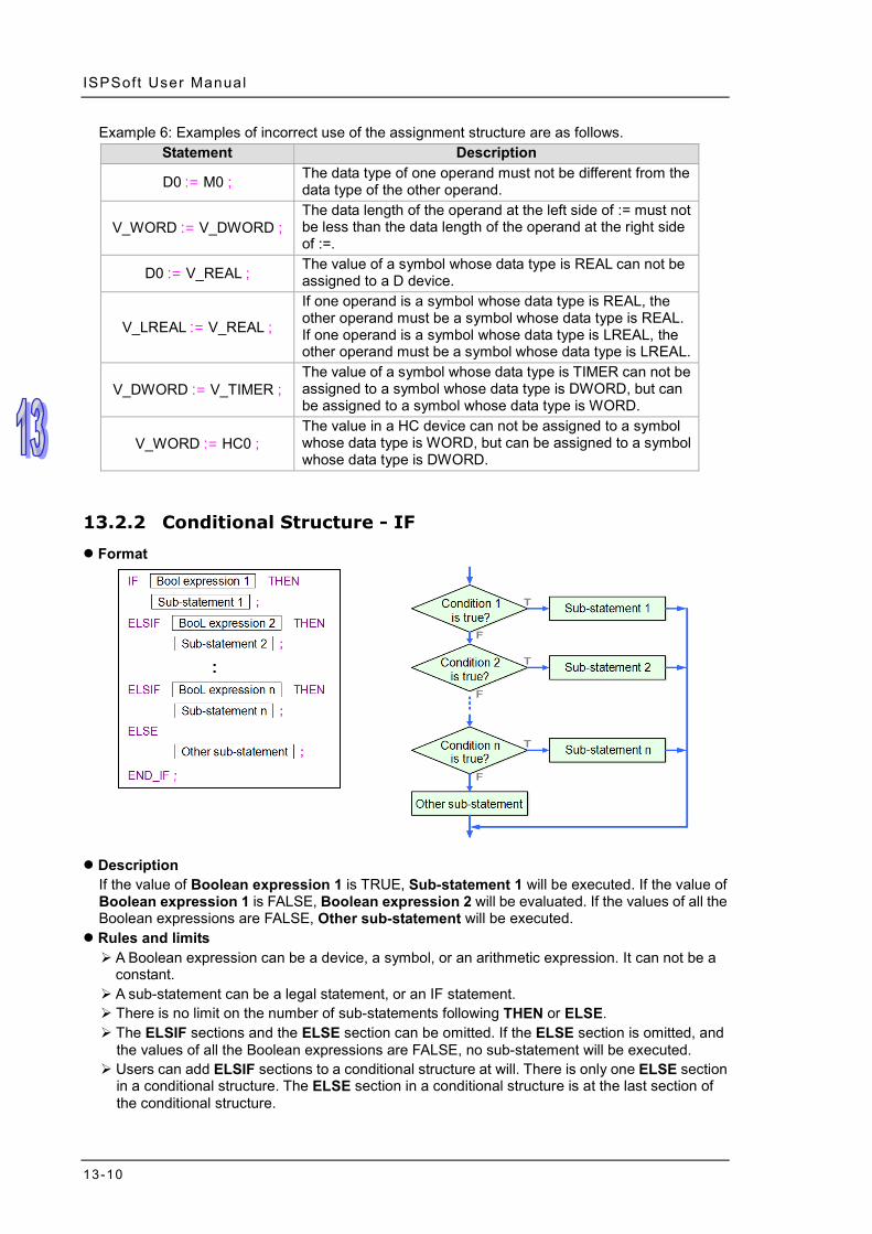
ISPSoft User Manual
13-10
Example 6: Examples of incorrect use of the assignment structure are as follows. Statement Description
D0 := M0 ; The data type of one operand must not be different from the data type of the other operand.
V_WORD := V_DWORD ; The data length of the operand at the left side of := must not be less than the data length of the operand at the right side of :=.
D0 := V_REAL ; The value of a symbol whose data type is REAL can not be assigned to a D device.
V_LREAL := V_REAL ;
If one operand is a symbol whose data type is REAL, the other operand must be a symbol whose data type is REAL. If one operand is a symbol whose data type is LREAL, the other operand must be a symbol whose data type is LREAL.
V_DWORD := V_TIMER ; The value of a symbol whose data type is TIMER can not be assigned to a symbol whose data type is DWORD, but can be assigned to a symbol whose data type is WORD.
V_WORD := HC0 ; The value in a HC device can not be assigned to a symbol whose data type is WORD, but can be assigned to a symbol whose data type is DWORD.
13.2.2 Conditional Structure - IF
Format
Description
If the value of Boolean expression 1 is TRUE, Sub-statement 1 will be executed. If the value of Boolean expression 1 is FALSE, Boolean expression 2 will be evaluated. If the values of all the Boolean expressions are FALSE, Other sub-statement will be executed.
Rules and limits A Boolean expression can be a device, a symbol, or an arithmetic expression. It can not be a
constant. A sub-statement can be a legal statement, or an IF statement. There is no limit on the number of sub-statements following THEN or ELSE. The ELSIF sections and the ELSE section can be omitted. If the ELSE section is omitted, and
the values of all the Boolean expressions are FALSE, no sub-statement will be executed. Users can add ELSIF sections to a conditional structure at will. There is only one ELSE section
in a conditional structure. The ELSE section in a conditional structure is at the last section of the conditional structure.

Chapter 13 Struc tured Texts
13-11
Example Example 1: If M0 is ON, M1 will be set to ON, and M2 will be set to OFF. If M0 is not ON, the step
will end. No matter what the value of M0 is, the value of M0 will be assigned to M0.
Example 2: If the value of DT is larger than 5, OUT_0 will be set to ON, and OUT_1 will be reset to OFF. If the value of DT is not larger than 5, the value of OUT_2 will be assigned to OUT_0 and OUT_1.

ISPSoft User Manual
13-12
Example 3: If M1 is ON, the value in D0 will be 1. If M1 is not ON, the PLC will evaluate M2. If M2 is ON, the value in D0 is 2. If M2 is not ON, the value in D0 will be 0.
13.2.3 Conditional Structure─CASE
Format
Description
The PLC judges whether the value of Integer expression is on the list of condition values. If the value of Integer expression is the same as a condition value on the list, the sub-statement following the condition value will be executed. If the value of Integer expression is not on the list of condition values, Other sub-statement under the keyword ELSE will be executed.
Rules and limits Integer expression in the figure above can be a device, a symbol, or an arithmetic expression.
It can not be a constant. The data type of Integer expression must be INT (-32768~32767) or DINT (-2147483648~2147483647). If a device is used as Integer expression, the system will automatically regard the value in the device as an integer. Besides, if an arithmetic expression is used as Integer expression, and the result of the operation is not an integer, the result will be rounded down to the nearest whole digit.
A condition value on the list can not be the same as another condition value on the list, and the condition values on the list must be integers. The range of condition values depends on the data type of Integer expression. If the data type is INT, the condition values must be in the

Chapter 13 Struc tured Texts
13-13
range of -32768 to 32767. If the data type is DINT, the condition values must be in the range of -2147483648 to 2147483647.
If the sub-statements following some condition values are the same, users can combine them. (a) If the condition values are not continuous values, they are separated by commas. For
example, 1, 3, 5: Sub-statement means that the sub-statement will be executed if the value of Integer expression is 1, 3, or 5.
(b) If the condition values are continuous values, the range of condition values can be indicated by the mark “..”. For example, 3..6: Sub-statement means that the sub-statement will be executed if the value of Integer expression is in the range of 3 to 6 (including 3 and 6). If the mark “..” is used, the value at the left side of “..” must be less than the value at the right side of “..”. For example, 6..3 : is an illegal range.
A sub-statement can be a legal statement, or another structure. There is no limit on the number of sub-statements following a condition value. The ELSE section can be omitted. If the ELSE section is omitted, and the value of Integer
expression is not on the list of condition values, no sub-statement will be executed. After a sub-statement is executed, the execution of the program will jump out of the CASE
structure. No jump instruction is needed. Example
Example 1: If the value in D0 is 1, M1 will be ON. If the value in D0 is 2, M2 will be ON. If the value in D0 is neither 1 nor 2, M0 will be ON.
Example 2: The value of the arithmetic expression D0+D1 is calculated first. If the result of the
operation is in the range of 1 to 3, M0 will be ON. If the result of the operation is 5 or 7, M1 will be ON. If the result of the operation is not on the list of condition values, no sub-statement will be executed, and the execution of the program will jump out of this structure.

ISPSoft User Manual
13-14
13.2.4 Loop Structure - REPEAT
Format
Description
The sub-statement is executed, and then the Boolean expression is evaluated. If the Boolean expression is evaluated as TRUE, the loop will be terminated. If the value of the Boolean expression is FALSE, the program in the structure will be executed repeatedly until the value of the Boolean expression is TRUE.
Rules and limits The Boolean expression can be a device, a symbol, or an arithmetic expression. It can not be a
constant. The sub-statement is executed before the Boolean expression is evaluated, and therefore the
sub-statement is executed at least once. The sub-statement can be a legal statement, or another structure. There is no limit on the
number of sub-statements in a REPEAT structure. One loop structure can be embedded in another loop structure. There are at most 64 loop structures.
If the value of the Boolean expression following UNTIL is TRUE, the loop will be terminated. To prevent an infinite loop, the operand in the Boolean expression following UNTIL can not be a device or a symbol which cannot be updated.
The X devices in a program are updated after the program is scanned. If users want to use an X device as the operand of the Boolean expression, they have to add an I/O update instruction to the structure, or update the X through an interrupt subroutine.

Chapter 13 Struc tured Texts
13-15
Example Example 1: The initial value of DT is 0. In the loop structure, the value of DT increases
progressively by 2. The loop will not be terminated until the value of DT is larger than 100.
Example 2: The initial value in D0 is 1, and the initial value in D10 is 5. After the loop is terminated,
the value in D0 will become 5*4*3*2*1.
13.2.5 Loop Structure - WHILE
Format
Description
The Boolean expression is evaluated. If the value of the Boolean expression is TRUE, the sub-statement will be executed. This repeats until the value of the Boolean expression becomes FALSE.
Rules and limits The Boolean expression can be a device, a symbol, or an arithmetic expression. It can not be a
constant. The sub-statement will be executed if the value of the Boolean expression is TRUE, and
therefore the sub-statement may not be executed. The sub-statement can be a legal statement, or another structure. There is no limit on the
number of sub-statements in a WHILE structure. One loop structure can be embedded in another loop structure. There are at most 64 loop structures.
If the value of the Boolean expression following WHILE is FALSE, the loop will be terminated. To prevent an infinite loop, the operand in the Boolean expression following WHILE cannot be a device or a symbol which cannot be updated.
The X devices in a program are updated after the program is scanned. If users want to use an X device as the operand of the Boolean expression, they have to add an I/O update instruction to the structure, or update the X through an interrupt subroutine.
Example Example 1: The initial value of DT is 0. In the loop structure, the value of DT increases
progressively by 2. The loop will not be terminated until the value of DT is larger than 100.

ISPSoft User Manual
13-16
Example 2: The REPEAT loop checks the Boolean expression after the sub-statement is
executed. The sub-statement in the REPEAT structure is executed once. After the REPEAT loop is terminated, the value in D0 will become 1. The WHILE loop checks the Boolean expression before the sub-statement is executed. The Boolean expression in the WHILE structure is evaluated as FALSE, and therefore the sub-statement in the WHILE structure is not executed. After the WHILE loop is terminated, the value in D1 will still be 0.
13.2.6 Loop Structure - FOR
Format
Description
The initial value of the symbol or the initial value in the device is the start value. Whenever the loop body is executed, the value of the symbol or the value in the device increases by the increment. If the value of the symbol or the value in the device is in the range of the start value to the end value, the loop body will be executed. If the value of the symbol or the value in the device is not in the range of the start value to the end value, the loop will be terminated.
Rules and limits The start value/end value/increment can be a device, a symbol, an arithmetic expression, or a
constant. The data type of the start value/end value/increment must be INT (-32768~32767) or DINT (-2147483648~2147483647). If a device is used as the start value/end value/increment, the system will automatically regard the value in the device as an integer. Besides, if an arithmetic expression is used as the start value/end value/increment, and the result of the

Chapter 13 Struc tured Texts
13-17
operation is not an integer, the result will be rounded down to the nearest whole digit. If the end value is less than the start value, the increment must be a negative number.
Otherwise, there will be an infinite loop. The data type of the symbol must be INT or DINT. If the symbol or the device takes part in the
operation, please prevent the value of the symbol or the value in the device from resulting in an infinite loop.
The sub-statement can be a legal statement, or another structure. There is no limit on the number of sub-statements in a FOR structure. One loop structure can be embedded in another loop structure. There are at most 64 loop structures.
After the value of the symbol or the value in the device increases by the increment, the system will check whether the value of the symbol or the value in the device is in the range of the start value to the end value. If an overflow occurs after the value of the symbol or the value in the device increases by the increment, there will be an infinite loop.
Example
The initial value of the symbol INDEX is 1. Whenever the loop body is executed, the value of INDEX increases by 2. After the loop body is executed for the fifth time, the value of INDEX will increase by 2, and the value of INDEX will become 11. Owing to the fact that the value INDEX is not in the range of 1 to 9, the loop is terminated. The initial value of the symbol SU is 0. After the loop is terminated, the value of SU will become 12+32+52+72+92.
13.2.7 Applied Instruction Structure
Format
Description
The applied instruction is executed. Rules and limits The state of the En pin does not need to be specified in the applied instruction. When the
statement is executed, the applied instruction is executed. An IF statement functioning as an En pin can be used with the applied instruction.
As long as the structure of the operands and the structure of the keywords are not destroyed, starting new lines is allowed.
The applied instruction is a statement, and therefore it ends with a semicolon. The operands specified in the applied instruction must be put in parentheses. The order in which the operands are arranged can not be changed. Please refer to instruction
manuals for more information. The applied instructions in ISPSoft do not support the assignment of values, and therefore
M0 := CMP(D0, D10, M0); is an illegal statement. As long as the structure of the applied instruction is unchanged, starting new lines is allowed.
Example Example 1: The instruction CMP is used with an IF statement.

ISPSoft User Manual
13-18
Example 2: The state of the En pin does not need to be specified in an applied instruction. If the instruction TMR is used, a statement about resetting the timer is required. Otherwise, the value of the counter will not become zero. For example, line 0004 in the figure below is a statement about resetting the timer.
13.2.8 Function Block Structure
Format
Description
The function block is executed. Rules and limits The state of the En pin of the function block does not need to be specified in the function block.
When the statement is executed, the function block is executed. An IF statement functioning as an En pin can be used with the applied instruction.
As long as the structure of the operands and the structure of the keywords are not destroyed, starting new lines is allowed.
The function block is a statement, and therefore it ends with a semicolon. The input/output pins of the function block and the corresponding operands must be put in
parentheses. A pin and the corresponding operand form a group. The groups are separated by commas. The data types of the operands are specified in the function block definition.
The function block before the parentheses is a function block instance rather than a function block definition, that is, the symbol before the parentheses is a symbol whose data type is a function block. Please refer to chapter 7 for more information about function block definitions and function block instances.
The assignment mark for an input pin is :=, and the assignment mark for an output pin is =>. The pins and the operands are arranged according to the definition of the function block. The
arrangement can not be changed. The En pin and the Eno pin are excluded. The input pins are listed above all the output pins. A pin of the VAR_IN_OUT class is an input pin. Please refer to the ladder diagram and the structured text below for more information.

Chapter 13 Struc tured Texts
13-19
Example
Example 1: When a statement which calls a function block is executed, the function block is executed.
Example 2: A function block is used with an IF statement.
Example 3: The value of the symbol CH determined which function block will be executed.
13.2.9 Blank Statement Format
Description

ISPSoft User Manual
13-20
If a statement is needed, but no action needs to be executed, a blank statement is used. Example
The For loop below shows that no action is executed. Owing to the blank statement, the execution of the program is delayed. Users can adjust the time for which the execution of the program is delayed by adjusting the number of times the loop body is executed.
13.2.10 RETURN Statement
Format
Description
A RETRUN statement is used in a function block in a structured text. It ends the program in the function block.
Example The programming language used to create the program in the function block FB0 is a structured text. After the upper part of the program is executed, the state of X0.0 will be judged. If X0.0 is ON, the execution will leave the current program. If X0.0 is OFF, the whole program in the function block will be executed.
13.2.11 EXIT Statement Format
Description An EXIT statement is used in a REPEAT loop, a WHILE loop, or a FOR loop. It is used to exit the loop.
Example Example 1: The loop below is a REPEAT loop. The loop will not be terminated until the value of
DT is 0. The IF structure in the loop is used with an EXIT statement. The initial value in D0 is 0. It increases by 1. The loop will not be terminated until the value in D0 is 100. As a result, the loop body will be executed 100 times at most. In the example below, the initial value of DT is 110. After the loop body is executed for the 100th time, the value of DT will become 10. In other words, the final value of DT will be 10. The value of DT will not decrease to 0.

Chapter 13 Struc tured Texts
13-21
Example 2: The loop below is a FOR loop. The value of the arithmetic expression D0* D10 is
calculated, and the result of the operation is stored in D0. The IF structure in the loop is used with an EXIT statement. The loop will not be terminated until the value in D0 is larger than 100. When the value in D10 increases to 5, the value in D0 is 1*2*3*4*5, and the loop is terminated.
13.3 Creating a Structured Text in ISPSoft
13.3.1 Editing Environment
Select the Structured Text (ST) option button in the Language section in the Create Program window. Please refer to section 5.4.1 for more information.
The environment in which a structured text can be edited is shown below. The table at the upper part of the window is a local symbol table, and the area at the lower part of the window is a working area. There are line numbers at the left side of the working area. Users can set the way in which the line numbers are displayed. Please refer to section 2.3.1 for more information. After a program editing window in which a structured text can be created is opened, the corresponding toolbar will appear in the ISPSoft window. The functions are described below.

ISPSoft User Manual
13-22
Icon Function
Inserting an example of an assignment structure
Inserting an example of an if statement
Inserting an example of a repeat loop
Inserting an example of a while loop
Inserting an example of a for loop
Inserting an example of a case statement
13.3.2 Creating a Structured Text
The way in which a structured text file is edited is similar to the way in which a text file is edited with a general text editor. If users want to create a structured text, they can type or modify text in the working area. If the users want to start a new line of text at a specific point, they can press Enter on the keyboard.
Besides, the users can click a line which will be edited, insert an example of a structure, and modify the structure.
If users want to select any amount of text, they can click where they want to begin the selection, hold down the left mouse button, and drag the pointer over the text that they want to select. The users can also click at the start of the selection, scroll to the end of the selection, and hold down Shift on the keyboard while they click where they want the selection to end.
If users type a symbol which has not been declared, they can click the symbol, click the right mouse button, and click Add Symbol on the context menu to open the Add Symbol window.
Local symbol table
Working area

Chapter 13 Struc tured Texts
13-23
While typing in the symbol, the system will autofill and show a list with variable symbols for users to choose from. Users can use “↑” and “↓” on the keyboard to select or simply click on the variable symbol you’d like to use.
13.3.3 Inserting Applied Instructions and Function Blocks
Users can insert an applied instruction or a function block in a structured text in ISPSoft in one of the two ways described below. Method 1
An applied instruction or a function block is inserted according to the format of the applied instruction or the format of the function block.
Method 2
Unfold the APIs section or the Function Blocks section in the project management area, and find the item which will be inserted. Select the item, and drag it to the position in which it will be inserted.
After the applied instruction or the function block is inserted, users have to type the corresponding

ISPSoft User Manual
13-24
operands according to the format of the applied instruction or the format of the function block.
Function block definitions can be dragged, but function block instances can not be dragged.
13.3.4 Bookmark
After lines are bookmarked, users can find or go to the lines easily. Adding/Removing bookmarks
If users want to add a bookmark to a line, they can select the line, click the right mouse button, click Bookmarks on the context menu, and select a bookmark number. If users want to remove the bookmark from a line, they can select the line, click the right mouse button, click Bookmarks on the context menu, and click the bookmark number corresponding to the bookmark added to the line. If the bookmark number clicked does not correspond to the bookmark added to the line, the bookmark number added to the line will become the bookmark number clicked. Besides, if users click the Edit menu, point to Bookmarks, and click Remove All Bookmarks, all the bookmarks in the working area will be removed. If users click a bookmark number which has been added to another line, the bookmark number will be moved to the line selected presently.
Going to a bookmark
Right-click the working area, point to Goto the Bookmark on the context menu, and click a bookmark number.

Chapter 13 Struc tured Texts
13-25
13.4 Example of a Structured Text
13.4.1 Explanation
The example is about the control of a tower light. A tricolor light and a buzzer are used. The control mechanisms for various device statuses are listed below. If more than one device status appears, the device status which is given precedence over the others is displayed.
State code Device status
Light Precedence Red
light Yellow light
Green light Buzzer
4 The device is malfunctions. ON OFF OFF Flash Highest
3 The device malfunctions. (The buzzer is turned off.) Flash OFF OFF OFF
2 The device is operating. OFF OFF ON OFF
1 The work is done. OFF Flash OFF OFF
0 The device is idling. OFF ON OFF OFF Lowest
13.4.2 Planning Hardware In this example, the AH500 series CPU module AHCPU530-EN, the digital I/O module AH16AP11R-5A, and the four-slot main backplane AHBP04M1-5A are used. The table below is an I/O allocation table.
Type ID Description Digital output Y0.0 Red light Digital output Y0.1 Yellow light Digital output Y0.2 Green light Digital output Y0.3 Buzzer
13.4.3 Planning a Program
(1) If the flag ERROR is ON, and the flag BUZZER_OFF is OFF, the state code will be 4. (2) If the flag ERROR is ON, and the flag BUZZER_OFF is ON, the state code will be 3. (3) If the flag ERROR is OFF, and the flag RUNNING is ON, the state code will be 2. (4) If the flags ERROR and RUNNING are OFF, and the flag COMPLETE is ON, the state code
will be 1. (5) If the flags ERROR, RUNNING, and COMPLETE are OFF, the state code will be 0. (6) Every state code corresponds to a light. The control of the tricolor light has many practical
applications, and the tricolor light can be displayed in various ways. Considering that a program can be expanded and reused, a function block is created.

ISPSoft User Manual
13-26
13.4.4 Creating a Program
Start ISPSoft, and then create a new project.
The hardware configuration in this example is the same as the hardware configuration in chapter 4. Please refer to chapter 4, and complete the hardware configuration.

Chapter 13 Struc tured Texts
13-27
Create a POU of the program type and a POU of the function block type in the project management area. The programming language used to create the POU of the program type and the POU of the function block type are structured texts.

ISPSoft User Manual
13-28
Create the flags and the digital outputs in the global symbol table.
When users edit the POU of the function block type, they have to create an input pin which receives the state code specified by the main program, and output pins which correspond to the three lights and the buzzer. Owing to the fact that the corresponding light will be displayed after the function block receives the state code specified by the main program, a CASE statement can be used in the function block. If there is another display mode, the users can add a state code, and insert a condition in the function block. The users can insert an example of a CASE statement in the working area, and modify the statement. They can also type the structured text shown below in the working area.
When the users edit the POU of the program type, they have to declare the symbol SC, which represents a state code, and the function block instance in the local symbol table. Owing to the fact that there is a precedence mechanism for the control of the tricolor light, an IF statement can be used in the main program. After a state code is specified, the function block must be called. The

Chapter 13 Struc tured Texts
13-29
state code is sent to the function block, and the result of the operation is sent to the digital output which is specified. The main program is shown below.
After the POU of the program type and the POU of the function block type are edited, the users can compile the program, download the parameters and the program to the CPU module, and test the program.

ISPSoft User Manual
13-30
MEMO

14-1
Chapter 14 Sequential Function Charts Table of Contents 14.1 Knowing Sequential Function Charts ...................................................14-2
14.1.1 Structure of a Sequential Function Chart ......................................14-2 14.1.2 Principle of a Sequential Function Chart .......................................14-2
14.2 Sequential Function Chart is ISPSoft ...................................................14-4 14.2.1 Steps and Actions .........................................................................14-4 14.2.2 Transitions ....................................................................................14-7 14.2.3 Simultaneous Divergence and Divergence of Sequence Selection …………………………………………………………………………..14-9 14.2.4 Simultaneous Convergence and Convergence of Sequence Selection …………………………………………………………………………14-10 14.2.5 Jump ........................................................................................... 14-11 14.2.6 Qualifier of an Action ..................................................................14-13
14.2.6.1 Qualifier Types .....................................................................14-13 14.2.6.2 Important Points About Qualifying an Action ........................14-17
14.2.7 Initial Step ...................................................................................14-18 14.3 Creating a Sequential Function Chart in ISPSoft ...............................14-19
14.3.1 Editing Environment ....................................................................14-19 14.3.2 Creating and Managing Actions and Transitions ........................14-21 14.3.3 Adding a Step .............................................................................14-23 14.3.4 Connecting a Transition in Parallel .............................................14-24 14.3.5 Connecting a Step in Parallel .....................................................14-25 14.3.6 Creating a Simultaneous Divergence and a Convergence of
Sequence Selection ....................................................................14-26 14.3.7 Creating a Divergence of Sequence Selection and a Simultaneous
Convergence ..............................................................................14-27 14.3.8 Inserting a Jump Point ................................................................14-28 14.3.9 Assigning Symbols to the Steps and the Transitions ..................14-29 14.3.10 Specifying an Initial Step ............................................................14-30 14.3.11 Assigning Actions .......................................................................14-30
14.4 Example of a Sequential Function Chart ............................................14-33 14.4.1 Explanation .................................................................................14-33 14.4.2 Planning Hardware .....................................................................14-34 14.4.3 Planning a Program ....................................................................14-34 14.4.4 Creating a Program ....................................................................14-35

ISPSoft User Manual
14-2
14.1 Knowing Sequential Function Charts
14.1.1 Structure of a Sequential Function Chart
A sequential function chart is one of the five languages defined by IEC 61131-3 standard. It is a powerful graphical technique for describing the sequential behavior of a control program. A sequential function chart and its corresponding flowchart are shown below. The main components of a sequential function chart are steps with associated actions, transitions with associated logic conditions, and directed links between steps and transitions.
14.1.2 Principle of a Sequential Function Chart
A sequence in a sequential function chart is depicted as a series of steps shown as rectangular boxes connected by vertical lines. Each step represents a particular state of the system being controlled. A transition is associated with a condition which, when true, causes the step before the transition to be deactivated and the step that follows the transition to be activated.

Chapter 14 Sequent ia l Funct ion Char t
14-3
Steps in a sequential function chart can be active or inactive. Actions are only executed for active steps. If a step is inactive, the transition follows it will not affect the execution of the program, and the actions associated with the step will not be executed. In a sequential function chart in ISPSoft, the steps must alternate with the transitions. If there are two continuous steps or transitions in a sequential function chart, the program can not be compiled.
The example above is the structure of a simple sequential function chart. ISPSoft also provides other flexible programming functions, such as the use of divergent and convergent paths, the use of modular actions and transitions, and the qualification of actions. These programming functions will be introduced in the sections below.

ISPSoft User Manual
14-4
14.2 Sequential Function Chart is ISPSoft
14.2.1 Steps and Actions
Every step in ISPSoft must be assigned a variable whose data type is STEP, and functions as a state flag. If the flag correspond to a step is ON, the step is active. Every symbol whose data type is STEP occupies an S device in the PLC. Please refer to operation manuals for more information about S devices. After a step is activated, the actions associated with the step will be executed according to the qualifiers. In ISPSoft, the actions can be modularized, and can be associated with different steps. A step can be associated with more than one action. Besides, every action has a qualifier that determines when the action is executed.
In ISPSoft, an action is a program code, and can be developed by means of a ladder diagram, an instruction list, a function block diagram, or a structured text. The actions which are created are listed in the project management area. The program editing window in which an action can be created differs from the window for a programming language in that there is no local symbol table in the program editing window in which an action can be created. In ISPSoft, the actions and the transitions in a sequential function chart share the same local symbol table.

Chapter 14 Sequent ia l Funct ion Char t
14-5
If users want to edit a sequential function chart, they have to create actions, assign the actions to the steps, and assign qualifiers to the actions. The Action Settings window and the corresponding action list are shown below.
Final scans are important procedures during the execution of a sequential function chart. After the execution of an action stops, the system will automatically execute a procedure to disable all the outputs in the action. If a final scan is executed, the coils driven by the instruction OUT will be OFF, the application instructions and the function blocks will not executed, the timers will be reset, the states of the coils driven by the instruction SET or RESET will remain unchanged, the counters will stop counting, the states of the contacts of the counters will remain unchanged, and the values in the counters will remain unchanged. Action0 in the figure below is an action associated with STEP_0, and is an N action. When STEP_0 is deactivated and STEP_1 is activated, the system executes a final scan.

ISPSoft User Manual
14-6
STEP_0 in the figure below is activated. M10 in Action0 is ON, and therefore M0 is ON, M1 is set to ON, M2 is reset to OFF, the value in T0 is 30, and the value in C0 is 5.
STEP_1 in the figure below is activated. Although M10 is ON, M0 is OFF, and T0 is reset. The state of M1, the state of M2, and the value in C0 remain unchanged.
For the AH5x1, AHxxEMC and AS series, users can set the Final Scan to run or not for every Action. The default is to run the Final Scan in the ISPSoft. To disable this function, users can right-click the Action that does not require a Final Scan to see a context menu and then deselect the Action/Transition > Enable Reset Function. After that users will see a red indicator situated in front of the Action that does not require a Final Scan. The state of an Action that does not run a Final Scan will stay the same as the previous state does, while the state of an Action that runs a Final Scan will be cleared.

Chapter 14 Sequent ia l Funct ion Char t
14-7
14.2.2 Transitions
When a transition is true, the active step immediately before the transition becomes inactive and the step immediately after the transition becomes active. A transition can be true anytime, but for a transition to activate the step following it, the step preceding it must be active when the transition is true. In ISPSoft, a transition can be a Boolean device or symbol, or a program code. If a transition is a logical operation, users can create a transition program, and assign the program to the transition. The transition programs which are created are listed in the project management area.
The programming languages which can be used to create transition programs include ladder diagrams, instruction lists, function block diagrams, and structured texts. The Boolean state in a transition program must be sent to a symbol name which is the same as the transition program name, whether the programming language used to create the transition program is a ladder diagram, an instruction list, a function block diagram, or a structured text. The symbol does not need to be declared. However, if there is a symbol name in a symbol table which is the same as a transition program name, an error occurs when the program is compiled. Besides, applied instructions and function blocks can not be used in a transition program, but comparison contacts and block logic instructions (NP, PN, and INV) can be used in a transition program.

ISPSoft User Manual
14-8
If the programming language used to create a transition program is a ladder diagram, the program code of the transition program must be composed of one network, and the output contact must be assigned a symbol name which is the same as the transition program name. Besides, multiple outputs are not allowed in a transition program created by means of a ladder diagram.
If the programming language used to create a transition program is a structured text, there is no limit on the number of lines of program code. However, a Boolean state in a transition program must be assigned to a symbol name which is the same as the transition program name.
If the programming language used to create a transition program is a function block diagram, the program code of the transition program must be composed of one network, and the output contact must be assigned a symbol name which is the same as the transition program name. Besides, multiple outputs are not allowed in a transition program created by means of a function block diagram.
If the programming language used to create a transition program is an instruction list, there is no limit on the number of lines of program code. OUT, SET, RST, and applied instructions can not be used in a transition program created by means of an instruction list. Besides, the output instruction in a transition program created by means of an instruction list must be TRANS, and the operand for TRANS must be assigned a symbol name which is the same as the transition program name.
When users create a transition program, a symbol name which is the same as the transition program name is added to the program code of the transition program. The users only have to create a conditional operation. Owing to the fact that the actions and the transitions in a sequential function chart share the same local symbol table, there are not local symbol tables in the program editing windows for the transitions. Users can not create a complex transition program. If a transition condition must undergo a complex operation, users can create the complex operation in an action associated with a step, create a

Chapter 14 Sequent ia l Funct ion Char t
14-9
condition flag in the action, and assign the flag to the transition following the step. Although users do not need to declare the symbols in the transition programs, the system assigns memories which function as flags to the symbols. As a result, users have to make sure that the symbols in the transition programs can be assigned a specific logic state. Otherwise, an error will occur if the program is executed. Take the transition program which is created by means of a structured text below for example. During the execution of the transition program for the first time, Tran4 will be ON if the result of (M0 AND M1) is ON. Since Tran4 is ON, it passes control to the next step. After the control is passed to the step preceding the transition program again, the transition program will be executed again. If the result of (M0 AND M1) is OFF, the statement following THEN will not be executed. Tran4 will still be ON because it is not updated. The system will evaluate the transition condition as TRUE, and the control will be passed to the next step. Adding an ELSE section to the transition program below is a better way to ensure that the symbol Tran4 is assigned a specific logic state. Users also have to pay attention to the same problem in a CASE sttructure.
14.2.3 Simultaneous Divergence and Divergence of Sequence Selection
Users can create divergent paths in a sequential function chart. There are two types of divergences. One is a simultaneous divergence, and the other is a divergence of sequence selection Simultaneous divergence
A simultaneous divergence is shown below. The divergent steps are connected by a double line. The characteristic of a simultaneous divergence is that the divergent steps share the same transition. When the transition is true, the steps are active. When Tran0 is true, STEP_0 becomes inactive, and STEP_1 and STEP_2 become active.
Divergence of sequence selection
A divergence of sequence selection is shown below. The characteristic of a divergence of sequence selection is that the divergent steps have their own transitions. When one transition is true, the step following the transition becomes active, and the other transitions are not evaluated. Consequently, if there are divergent paths, only one path is taken at a time. Besides, the transitions are evaluated from left to right. If several transitions are true simultaneously, only the step following the leftmost transition will be activated. When Tran2 is true, STEP_0 becomes inactive, and STEP_2 becomes active. Tran1 is not evaluated, and STEP_1 remains inactive.

ISPSoft User Manual
14-10
14.2.4 Simultaneous Convergence and Convergence of Sequence Selection
The divergent paths in a sequential function chart must be converged. There are two types of convergences. One is a simultaneous convergence, and the other is a convergence of sequence selection. Simultaneous convergence
A simultaneous convergence is shown below. The convergent steps are connected by a double line. The characteristic of a simultaneous convergence is that the convergent steps are connected to the same transition. The transition will not be evaluated until the convergent steps preceding the transition are activated. After STEP_1 and STEP_2 are activated, Tran3 will be evaluated. When Tran3 is true, STEP_1 and STEP_2 become inactive, and STEP_3 becomes active.
Convergence of sequence selection
A convergence of sequence selection is shown below. The characteristic of a convergence of sequence selection is that the convergent steps have their own transitions. When one transition is true, the next step becomes active. If there is another convergent step which is activated, the step will be active until the transition following the step is true. When the transition is true, the step following the transition becomes active. Consequently, if a convergence of sequence selection is used in a sequential function chart, several steps following the convergence may be activated. If users use a convergence of sequence selection in a sequential function chart, they have to make sure that the program is not confused. When Tran1 is true, STEP_1 becomes inactive, and STEP_3 becomes active. If Tran2 is true, STEP_2 will be inactivated, and STEP_3 will be activated again.

Chapter 14 Sequent ia l Funct ion Char t
14-11
14.2.5 Jump
The use of a jump structure in a sequential function chart results in the passing of control to a step which is specified. There is at least one jump point indicating that the passing of control will occur once the transition preceding the jump point is true in a sequential function chart. Users can use jump structures quite freely. If they use a jump structure in a sequential function chart, they have to make sure that the program is not confused. The program below is a sequential function chart where there is a divergence of sequence selection. If Tran2 is true, control will be passed to STEP2. When Tran4 is true, it passes control to STEP1 through a jump. When Tran5 is true, it passes control to STEP0.
If users use a jump structure in a sequential function chart, the step specified must be a step in the same sequential function chart. If the step specified is not in the same sequential function chart, and is declared in a local symbol table or the global symbol table, an error occurs when the program is compiled If control needs to be passed from a step in a sequential function chart to a step in another

ISPSoft User Manual
14-12
sequential function, users can make use of the characteristics of steps and the characteristics of transitions. Users can declare the step or the transition which is the destination of a jump in the global symbol table. When the condition of the jump is met, the step or the transition declared is set to ON. The condition of the jump can be created in an action. The figure below shows that SFC_A is executed first. SFC_B will be executed after SFC_A is executed, and SFC_A will be executed after SFC_B is executed. User can achieve the jumps by means of the characteristics of transitions.
The steps SP_A and SP_B in the example below are used to express the sequential function chart which will be executed. They are preceded and followed by steps. Besides, the transitions RUN_A and RUN_B are declared in the global symbol table. When the program is executed, the step WAIT in SFC_A and the step WAIT in SFC_B are activated, and the action INITIALIZE associated with WAIT in SFC_A and the action INITIALIZE associated with WAIT in SFC_B are executed. INITIALIZE in SFC_A sets the transition RUN_A to ON during the first scan cycle, and therefore control is passed to SP_A. INITIALIZE in SFC_B sets the transition RUN_ B to OFF during the first scan cycle, and therefore control is not passed to SP_B. When the step JUMP in SFC_A is activated, the action associated with JUMP sets the transition RUN_B to ON, and resets RUN_A to OFF. When RUN_B is set to ON, control is passed to the step SP_B. Besides, the transition following JUMP in SFC_A is a special relay which is always ON, and therefore control is passed to the step WAIT. Owing to the fact that RUN_A is set to OFF, control is not passed to SP_A. RUN_A will not be set to ON until the action associated with JUMP in SFC_B is executed. The use of WAIT and JUMP in SFC_A serves to set RUN_B to ON, and the use of WAIT and JUMP in SFC_B serves to set RUN_A to ON. WAIT and JUMP in SFC_A and WAIT and JUMP in SFC_B actually have little significance. If the program is applied to an AH/AS series CPU module, users can assign the qualifier P or P1 to the actions associated these steps. Please refer to section 14.2.6 for more information.

Chapter 14 Sequent ia l Funct ion Char t
14-13
14.2.6 Qualifier of an Action
In ISPSoft, users can define the execution of an action by qualifying the action. However, users can not qualify the actions in the program in a DVP series PLC. Consequently, the actions in the program in a DVP series PLC are N actions.
The step name is displayed here.
Users can select qualifiers for the actions associated with the step.
Users can specify qualifiers related to time.
Users can select actions which are qualified.
Users can make comments on the step.
14.2.6.1 Qualifier Types
N (Normal) When a step is activated, the N action associated with the step is executed. When the step is inactivated, the system executes a final scan to disable all the outputs in the N action. However, the outputs which use the instructions similar SET are not disabled. The actions in the program in a DVP series PLC are N actions.
S (Set) When a step is activated, the S action associated with the step is executed. Even if the step is inactivated, the S action will still be executed. When STEP_1 in the figure below is activated, Action1 and Action2 are executed. When Tran1 is true, STEP_1 becomes inactive. Once STEP_1 is inactivated, the execution of Action1 will stop, the system will execute a final scan, and Action2 will still be executed.
D (Delay)
The D action associated with a step is not executed at the time when the step is activated. The execution of the D action is delayed for a certain amount of time. If the transition following the step becomes true before the D action is executed, the step will be inactivated, control will be passed to the next step, and the D action will not be executed. When the step is activated again,

ISPSoft User Manual
14-14
the delay is measured again. Action1 in the figure below is not executed at the time when STEP_1 is executed. The execution of Action1 is delayed for two seconds. If STEP_1 is inactivated before Action1 is executed, Action1 will not be executed.
SD (Set Delay)
The SD action associated with a step is not executed at the time when the step is activated. The execution of the SD action is delayed for a certain amount of time. If the SD action is executed, it will still be executed after the step is inactivated. Besides, if the transition following the step becomes true before the SD action is executed, control will be passed to the next step, and the delay will still be measured. A certain amount of time has elapsed before the SD action is executed.
DS (Delay Set) A DS action is similar to a SD action. However, if the transition following a step becomes true before the SD action associated with the step is executed, the delay will not be measured, and the SD action will not be executed. When the step is activated again, the delay is measured again. If the DS action is executed, it will still be executed after the step is inactivated. Action1 and Action2 are not executed at the time when STEP_1 is activated. The execution of Action1 and the execution of Action2 are delayed for two seconds. There are two situations which need to be considered. (a) STEP_1 is activated for more than two seconds.
Action1 and Action2 will be executed after STEP_1 has been executed for two seconds. Even if STEP_1 is inactivated, Action1 and Action2 will still be executed.
(b) STEP_1 is activated for less than two seconds. After control is passed to the next step, the delay of Action1 will still be measured. Two seconds has elapsed before Action1 is executed. However, after the control is passed to the next step, the delay of Action2 will not be measured, and Action2 will not be executed.
L (Limit)
When a step is activated, the L action associated with the step is executed. If the L action has been executed for a certain amount of time before control is passed to the next step, the execution of the L action will stop automatically, and the system will execute a final scan. If the control is passed to the next step before the time specified has elapsed, the execution of the L action will stop.
SL (Set Limit) When a step is activated, the SL action associated with the step is executed. If the SL action has been executed for a certain amount of time before control is passed to the next step, the execution of the SL action will stop automatically, and the system will execute a final scan. If the control is passed to the next step before the time specified has elapsed, the execution of the SL action will stop after the time specified has elapsed. When STEP_1 is activated, Action1 and Action2 are executed. There are two situations which

Chapter 14 Sequent ia l Funct ion Char t
14-15
need to be considered. (a) STEP_1 is activated for more than two seconds.
After Action1 and Action2 have been executed for two seconds, the execution of Action1 and the execution of Action2 will stop, and the system will execute final scans.
(b) STEP_1 is activated for less than two seconds. After control is passed to the next step, the execution of Action1 will stop, and the system will execute a final scan. The execution of Action2 will stop after two seconds have elapsed.
R (Reset)
When a step is activated, the R action related to the step is not executed, and the system executes a final scan. An action qualified by S, SD, DS, or SL will not be executed if it is qualified by R. Suppose that Action0, Action1, and Action2 are executed during the activation of STEP_0, and will be executed until control is passed to STEP_2. After the control is passed to STEP_2, the execution of Action0 and the execution of Action2 will stop, and the system will execute final scans. Owing to the fact that Action1 is not qualified by R, it will still be executed after the control is passed to STEP_2.

ISPSoft User Manual
14-16
P (Pulse) During the first scan cycle, the P action associated with a step is executed when the step is activated. During the second scan cycle, even if the step is activated, the outputs will be disabled, and the system will execute a final scan. During the first scan cycle, Action1 is executed when STEP_1 is activated. Owing to the fact that SM400 is ON, M1 and M2 are ON. During the second scan cycle, the system inactivates Action1. Although SM400 is still ON, M2 becomes OFF. M1 is driven by the instruction SET, and therefore it remains ON.
P1 (Raising Pulse)
The P1 action associated with a step is executed only when the step is activated during the first scan cycle. Besides, the system will not execute a final scan after the execution of the P1 action stops. Consequently, although an action where the instruction OUT or TMR is used is allowed to be qualified by P1, a warning appears when the program is compiled. During the first scan cycle, Action1 is executed when STEP_1 is activated. If M1 is ON, M2 will be ON. Action1 is executed only when STEP_1 is activated during the first scan cycle. Besides, the system will not execute a final scan after the execution of Action1 stops. Consequently, the state of M2 will not change even if the state of M1 changes.
P0 (Falling Pulse)
The P0 action associated with a step is executed only when the step is inactivated during the first scan cycle. Besides, the system will not execute a final scan after the execution of the P0 action stops. Consequently, although an action where the instruction OUT or TMR is used is allowed to be qualified by P1, a warning appears when the program is compiled. When STEP_1 is activated, Action1 is not executed. Action1 will not be executed until Tran1 is true. If M1 is ON, M2 will be ON. Action1 is executed only when STEP_1 is inactivated during the first scan cycle. Besides, the system will not execute a final scan after the execution of Action1 stops. Consequently, the state of M2 will not change even if the state of M1 changes.

Chapter 14 Sequent ia l Funct ion Char t
14-17
14.2.6.2 Important Points About Qualifying an Action
Once an action qualified by S is executed, it will still be executed even if it is qualified by N or P. The execution of the action stops only when the action is qualified by R. If there is an action which is qualified by S, users have to check whether they have to assign R to the action to stop the execution of the action. When STEP_0 is activated, Action0 and Action1 are executed. After control is passed to STEP_1, Action0 and Action1 will still be executed even if they are qualified by N and P respectively. The execution of Action1 will stop after control is passed to STEP_2. Action0 is never qualified by R, and therefore it will be executed all the time.
Except the R qualifier, when assigning a time-related qualifier for an Action, the qualifier can only
be used in the SFC instruction once. In other words, if an action is qualified by D, SD, DS, L, or SL, no other qualifiers can be used for the action, except the R qualifier. From the example shown below, we can see that in the STEP_0, the Action0 and Action1 are qualified by D and L respectively. And in the STEP_1, the Action0 and Action1 are qualified by N and R. The usage of Action 0 being assigned with D in the STEP_0 and N in the STEP_1 is wrong and will cause error to occur. The usage of Action 1 being assigned with Lin the STEP_0 and R in the STEP_1 is correct, since R can be added to an Action with more than 1 qualifier.

ISPSoft User Manual
14-18
14.2.7 Initial Step
During the execution of a sequential function chart, every step is activated in turn and cyclically. It is necessary to define a step as an initial step which is activated when the program is executed for the first time. In ISPSoft, the initial step in a sequential function chart is drawn as a box with a double line. Besides, there is only one initial step in a sequential function chart.
Any step in a sequential function chart in an AH/AS series CPU module can be defined as the initial step in the sequential function chart. When a sequential function chart in an AH/AS series CPU module is executed for the first time during the operation of the CPU module, the initial step in the sequential function chart is the step which is activated first. If there is a sequential function chart in a DVP series PLC, the sequential function chart will not be executed until the instruction SET used in another POU activate a step in the sequential function chart. Users can not define a step in a sequential function chart in a DVP series PLC as the initial step in the sequential function chart, and the first step in a sequential function chart in a DVP series PLC is always the initial step in the sequential function chart. The real initial step in a sequential function chart in a DVP series PLC is the device or the symbol driven by the instruction SET used in another POU. An example of executing a sequential function chart in DVP series PLC is shown below. Users have to determine which step in a sequential function chart is the initial step in the sequential function chart, declare the step in the global symbol table, and apply the instruction SET to the step in another POU. In the program code where the instruction SET is applied to the step, the condition contact or the logical output preceding the step must be prevented from becoming ON again during the execution of the program. Otherwise, the step will be ON, and the sequential function chart will be executed incorrectly. The special relay M1002 is highly recommended. The characteristic of M1002 is that M1002 is ON during the first scan cycle.

Chapter 14 Sequent ia l Funct ion Char t
14-19
14.3 Creating a Sequential Function Chart in ISPSoft
14.3.1 Editing Environment
Select the Sequential Function Chart (SFC) option button in the Language section in the Create Program window. Please refer to section 5.4.1 for more information about creating a sequential function chart. In addition, users have to pay attention to the following two points when they create a sequential function chart. (a) The programming language used to create a POU of the function block type can not be a
sequential function chart. (b) If the programming language used to create a POU of the program type is a sequential function
chart, the POU of the program type can only be assigned to a cyclic task.
The environment in which a sequential function chart can be edited is shown below. The table at the upper part of the window is a local symbol table, and the area at the lower part of the window is a working area. The working area is like a checkerboard. The steps and the transitions are put in squares. If users click an object or the square where the object is put, the object will be selected, and a yellow frame will appear.
Local symbol table
Working area

ISPSoft User Manual
14-20
After a program editing window in which a sequential function chart can be created is opened, the corresponding toolbar will appear in the ISPSoft window. The functions are described below.
Icon Keyboard shortcut
Function
Shift+F1 Adding a step to the top of the object selected.
Shift+F2 Adding a step to the bottom of the object selected
Shift+F3 Connecting a transition to the transition selected in parallel, and putting the transition at the right side of the transition selected
Shift+F4 Connecting a transition to the transition selected in parallel, and putting the transition at the left side of the transition selected
Shift+F5 Connecting a step to the step selected in parallel, and putting the step at the right side of the step selected
Shift+F6 Connecting a step to the step selected in parallel, and putting the step at the left side of the step selected
Shift+F7 Creating a simultaneous divergence and a convergence of sequence selection at the right side of the step selected
Shift+F8 Creating a simultaneous divergence and a convergence of sequence selection at the left side of the step selected
Shift+F9 Creating a divergence of sequence selection and a simultaneous convergence at the right side of the transition selected
Shift+F10 Creating a divergence of sequence selection and a simultaneous convergence at the left side of the transition selected
Shift+F11 Inserting a jump point

Chapter 14 Sequent ia l Funct ion Char t
14-21
Users can edit the sequential function chart by means of the toolbar. They can also edit the sequential function chart by clicking an object in the working area, and clicking an item on the context menu. To ensure that the sequential function chart is a complete and legal sequential function chart, the editing function which can be used varies with the object selected.
14.3.2 Creating and Managing Actions and Transitions
If users want to create an action, they have to unfold the sequential function chart section in the project management area, select Actions, right-click Actions, and then click Add. Type an action name in the New Action window, and select a programming language in the New Action window.

ISPSoft User Manual
14-22
If the users want to create a transition, they have to unfold the sequential function chart section, selection Transitions, right-click Transitions and then click Add, type a transition name in the New Transition window, and select a programming language in the New Transition window.
After the users double-click the action or the transition created in the project management area, the corresponding program editing window will appear. In the window for the transition, there is a symbol name which is the same as the transition program name. Please refer to section 14.2.1~section 14.2.2 for more information about editing actions and transitions. The action and the transition are edited in much the same way as a general POU is. However, there are no local symbol tables in the window for the action and the window for the transition. If users want to declare a local symbol table, they have to declare it in the window for the sequential function chart. Besides, the actions and the transitions in a sequential function chart share the same local symbol table. Please refer to chapter 10 ~ 15 for more information about programming languages.
*. If the transition create is assigned to a transition in the sequential function chart, the window for the transition will be opened after users double-click the transition in the sequential function chart.

Chapter 14 Sequent ia l Funct ion Char t
14-23
If the users want to manage the action or the transition created in the project management area, they can right-click the action or the transition and then click Add. The users have to notice that the action can not be copied into the Transition section, and the transition can not be copied into the Action section.
14.3.3 Adding a Step
(1) Select a step in the working area.

ISPSoft User Manual
14-24
(2) If users want to put a step to the top or the bottom of the step selected, they can click for the top or for the bottom direction on the toolbar. Or users can also right-click the step selected and click the suitable option, for the step to be added to the before or after the cursor.
14.3.4 Connecting a Transition in Parallel
(1) Select a transition in the working area.
(2) If users want to put a transition at the right/left side of the transition selected, they can click
on the toolbar for the right direction or for the left direction. Or users can also right-click the transition selected and click the suitable option, for the transition to be branched to the right or left direction.

Chapter 14 Sequent ia l Funct ion Char t
14-25
14.3.5 Connecting a Step in Parallel
(1) Select a step in the working area. (The topmost step in the working area can not be connected to another step in parallel.)
(2) If users want to put a step at the right/left side of the step selected, they can click on the toolbar for the right direction or for the left direction. Or users can also right-click the simultaneous step selected and click the suitable option, for the simultaneous step to be added to the right or left direction.

ISPSoft User Manual
14-26
14.3.6 Creating a Simultaneous Divergence and a Convergence of Sequence Selection
(1) Select a step in the working area. The step selected can not be the topmost step in the sequential function chart.
(2) If users want to create a simultaneous divergence and a convergence of sequence selection at
the right/left side of the step selected, click on the toolbar for the right direction or for the left direction. Or users can also right-click the step selected and click the suitable option, for the step and a transition to be added to the right or left direction.

Chapter 14 Sequent ia l Funct ion Char t
14-27
14.3.7 Creating a Divergence of Sequence Selection and a Simultaneous Convergence
(1) Select a transition in the working area. The transition selected can not be the bottommost transition in the sequential function chart.
(2) If users want to create a divergence of sequence selection and a simultaneous convergence at the right/left side of the step selected, click on the toolbar for the right direction or for the left direction. Or users can also right-click the step selected and click the suitable option, for the transition and a step to be added to the right or left direction.

ISPSoft User Manual
14-28
14.3.8 Inserting a Jump Point
(1) Select the bottommost step or the bottommost transition on a divergent path in the working area.
(2) After users click on the toolbar, a jump point will be inserted. The users can also insert a jump point by right-clicking the step or the transition selected and click Jump to a Step.

Chapter 14 Sequent ia l Funct ion Char t
14-29
14.3.9 Assigning Symbols to the Steps and the Transitions
After the editing of a sequential function chart is complete, users must assign symbols to the steps and the transitions in the sequential function chart. Click a step or a transition first. After a yellow frame appears, users can type partial step name to see a dropdown list and then click to select the step or the transition. Click the button at the right side of the box which appears, and select an item created.
The users can also assign a symbol to a step or a transition by means of the keyboard. They can move the yellow frame by pressing the up/down key on the keyboard. After the users select a step or a transition, they can press Enter on the keyboard. The users can type characters in the box which appears and a drop-down list will appear. The users can select a symbol on the drop-down list by the up/down key on the keyboard. After the editing of the box is complete, the users can press Enter on the keyboard to jump to the next box. If the users want to end the editing, they can press Esc on the keyboard. Besides, if the step name the users type in the box for a step is symbol which is not declared, the Add Symbol window will appear after the users press Enter on the keyboard. However, if the transition name the users type in the box for a transition is a symbol which is not

ISPSoft User Manual
14-30
declared, the Add Symbol will not appear.
*.Transitions can be assigned as the element BOOL for the structure variable. Please refer to chapter 8, for more
information about structure. *. Users can decide whether to allow the system to open the Add Symbol window automatically or not. Please refer
to section 2.3.1 for more information about the setting.
14.3.10 Specifying an Initial Step
Users can define a step in a sequential function chart in an AH/AS series CPU module as the initial step in the sequential function chart whereas they can not define a step in a sequential function chart in a DVP series PLC as the initial step in the sequential function chart. If users want to define a step in a sequential function chart as the initial step in the sequential function chart, they have to select the step in the working area, right-click the step, and click Set Initial on the context menu.
*. Please refer to section 14.2.7 for more information about activating the steps in a DVP series PLC.
14.3.11 Assigning Actions (1) Select the step to which an action will be assigned, right-click the step, and click Action
Settings… on the context menu to open the Action Settings window. If the step is not declared, the system will not allow the assignment of an action to the step.

Chapter 14 Sequent ia l Funct ion Char t
14-31
(2) Select an action in an Associate Action drop-down list cell in the Action Settings window.
(3) After an action is selected, users have to select a qualifier in the Qualify drop-down list cell for
the action. If the qualifier selected is related to time, the users have to type a time interval in the Time (sec) cell for the qualifier. A second is a measurement unit of a time interval. Besides, the users can only type an integer. (The users can not qualify the actions in the program in a DVP series PLC.)
(4) If the users want to make comments on the step, they can type the comments in the box at the
lower part of the window.
(5) After the users right-click an item on the list, they can click Add, Insert, Delete, or Select All on
the context menu. When there are more than one action that needed to be selected, users can hold the Control button on the keyboard and simultaneously use the mouse to click and select the actions. Users can also hold the Shift button on the keyboard and simultaneously use the mouse to click the first action needed and the last action needed to set the selection range.

ISPSoft User Manual
14-32
Item Function Add Adding a row to the bottom of the cell selected.
Insert Inserting a row above the cell selected Delete Deleting the row selected
Select All Selecting all the items (6) After the assignment of actions is complete, users can click OK. A list of the actions will appear
at the right side of the step.
Additional remark ISPSoft has a new button for quickly adding and set up actions. Users can click the button in the STEP to open a New Action window to add and set up actions. Once the creation is done, click the OK button to have the action added to the step you have selected.

Chapter 14 Sequent ia l Funct ion Char t
14-33
14.4 Example of a Sequential Function Chart
14.4.1 Explanation
The example is about the rotation of two plates. The figure below is a flow chart. The actual equipment is also diagramed below. The inlet is at the right side of the platform, and the outlet is at the left side of the platform. After a plate enters the inlet, and the plate in the outlet makes its exit from the outlet, the rotator in the middle of the platform will rotate 180 degrees. After the rotator rotates, the plate which entered the inlet will be in the outlet, and the clamp from which the plate made its exit will receive another plate. During the whole process, a plate enters the inlet independently, and the plate in the outlet makes its exit from the outlet independently. However, the rotator does not rotate independently. When the system begins to operate, the cylinders under the clamps open the clamps. After the clamps are opened, the system will send readiness signals. After the readiness signals are sent, a plate will enter the inlet, and the plate in the outlet will make its exit from the outlet. After a plate enters the inlet, and the plate in the outlet makes its exit from the outlet, the system will receive completion signals, the corresponding readiness signals will be set to OFF, and the clamps will be closed. After the system makes sure that the clamps are closed, the system will send a trigger signal. After the rotator rotates 180 degrees, and the system receives a completion signal, the next cycle will begin.

ISPSoft User Manual
14-34
14.4.2 Planning Hardware In this example, the AH500 series CPU module AHCPU530-EN, the digital I/O module AH16AP11R-5A, and the four-slot main backplane AHBP04M1-5A are used. The table below is an I/O allocation table.
Type ID Description Digital input X0.0 Completion signal Digital input X0.1 Completion signal Digital input X0.2 Completion signal
Digital input X0.3 (Inlet) Cylinder─Opening sensor
Digital input X0.4 (Inlet) Cylinder─Closing sensor
Digital input X0.5 (Outlet) Cylinder─Opening Sensor
Digital input X0.6 (Outlet) Cylinder─Closing Sensor Digital output Y0.0 Readiness signal Digital output Y0.1 Readiness signal Digital output Y0.2 Trigger signal Digital output Y0.3 (Inlet) Clamp Digital output Y0.4 (Outlet) Clamp
14.4.3 Planning a Program
(1) The procedure for initializing the system is to reset the trigger signal and the readiness signals to OFF until the condition for the operation of the system is met. In this example, when the operation flag is ON, and the error flag is OFF, the condition for the operation of the system is met.
(2) Once the system begins to operate, the cylinders under the clamps will open the clamps (Y0.3 and Y0.4), and the system will make sure that the opening sensors (X0.3 and X0.5) are ON.
(3) After the system makes sure that the clamps are opened, the system will send readiness signals (Y0.0 and Y0.1) to inform the work stations connecting to the system.
(4) After a plate enters the inlet, the system will receive a completion signal (X0.0), and delay the closing of the clamp in the inlet (Y0.3) for one second.
(5) After the plate in the outlet makes its exit from the outlet, the system will receive a completion signal (X0.1), and delay the closing of the clamp in the outlet (Y0.4) for one second.
(6) After the system makes sure that the closing sensors (X0.4 and X0.6) are ON, the system will send a trigger signal (Y0.2). After the rotator rotates 180 degrees, the system will receive a completion signal (X0.2), and the procedure for initializing the system is carried out again.

Chapter 14 Sequent ia l Funct ion Char t
14-35
14.4.4 Creating a Program
Start ISPSoft, and then create a new project.
The hardware configuration in this example is the same as the hardware configuration in chapter 4. Please refer to chapter 4, and complete the hardware configuration.

ISPSoft User Manual
14-36
Create a POU of the program type in the project management area. The programming language used to create the POU of the program type is a structured text.
Create the flags, the digital input, and the digital outputs in the global symbol table.

Chapter 14 Sequent ia l Funct ion Char t
14-37
Declare the steps shown below in the local symbol table in the POU of the program type.
Create the sequential function chart shown below. The initial step in the sequential function chart is the first step in the sequential function chart.

ISPSoft User Manual
14-38
Create a transition called Go and a transition called All_Done under the Transitions section in the project management area.
After a transition called Go and a transition called All_Done are created under the Transitions section in the project management area, users have to write the programs shown below.
Create the actions which are shown below under the Actions section in the project management area.

Chapter 14 Sequent ia l Funct ion Char t
14-39
After the actions are created under the Actions section in the project management area, the users have to write the programs shown below.

ISPSoft User Manual
14-40
After the users write the action programs and the transition programs, they have to assign symbols to the transitions in the sequential function chart. All the symbols assigned to the transitions in the sequential function chart are symbols in the global symbol except GO and All_Done.

Chapter 14 Sequent ia l Funct ion Char t
14-41
The users have to assign the actions to the steps in the sequential function chart, and assign qualifiers to the actions.
The writing of the program has been completed so far. The users can try to compile the program, download the parameters and the program to the CPU module, and test the program by themselves.

ISPSoft User Manual
14-42
MEMO

15-1
Chapter 15 Continuous Function Charts
Table of Contents 15.1 Continuous Function Charts (CFC) ...........................................................15-2
15.1.1 About Continuous Function Charts ...................................................15-2 15.1.2 Things to Note When Using CFC .....................................................15-2 15.1.3 CFC Programming in ISPSoft...........................................................15-2 15.1.4 CFC Editing Toolbar .........................................................................15-3 15.1.5 Shortcuts for CFC Programing .........................................................15-4
15.2 Creating a CFC in ISPSoft ........................................................................15-5 15.2.1 Selecting Objects .............................................................................15-5 15.2.2 Input/Output Nodes and Logic Gates ...............................................15-5
15.2.2.1 Inserting Nodes or Gates .......................................................15-6 15.2.2.2 Add/Delete a Pin ....................................................................15-7
15.2.3 Changing a Pin Type ........................................................................15-8 15.2.4 Connecting objects and Canceling Connections ..............................15-9 15.2.5 Instructions and Function Blocks ......................................................15-9
15.2.5.1 Inserting an Instruction ........................................................ 15-11 15.2.5.2 Inserting a Function Block ...................................................15-12
15.2.6 Deleting objects ..............................................................................15-13 15.2.7 Editing Devices or Symbols ............................................................15-15 15.2.8 Activating/Inactivating an Object ....................................................15-16 15.2.9 Inserting a Comment ......................................................................15-16 15.2.10 Changing the Order in Which Objects are Executed ...............15-18 15.2.11 Displaying/Hiding Information..................................................15-19

ISPSoft User Manual
15-2
15.1 Continuous Function Charts (CFC)
15.1.1 About Continuous Function Charts
Continuous Function Chart (CFC) is a PLC programming language in extension to the IEC 61131-3 standard. CFC is often used in the area of motion control. The most significant feature is its graphical programming language basing on the function block diagram language. Comparing to other PLC programming languages, CFC can provide a more logical relation between input and output and a more clear execution order of the program. The operation principle of CFC will not be covered in this chapter; this chapter will only focus on the creation and operation of CFC in ISPSoft.
15.1.2 Things to Note When Using CFC
It supports keyboards but does not support the instructions of LD, LDI, LDP, and LDF. Users can type the register or the name of the variable, and the system will add input node in the back.
Inputted data is not case-sensitive, any uppercase or lowercase character can be entered. For example, OUT, Out and out are all correct. Common positional numeral systems: Decimal range: 2345 Hexadecimal range: 16#5BA0 Floating point number: 4.123
*. The K and H notations are supported.
There is no limit on the number of the loops for CFC to edit. But the size of a edited programs should not be larger than the memory size. The input pin of nodes, logic gates, instructions, and function blocks can only be from one origin. But the targets of the output pin can be multiple.
15.1.3 CFC Programming in ISPSoft
When creating a POU, select Continuous Function Chart (CFC) in the Language selection section and then users can see the created program in the project management area. Refer to section 5.4.1 or more information.
Below is the editing area for CFC in the ISPSoft. The upper section is for Local Symbols to be declared. And the lower section is for CFC program editing, including the input/export nodes and

Chapter 15 Cont inuous Funct ion Charts
15-3
logic gate. The number on the upper right corner of the object is the execution order.
15.1.4 CFC Editing Toolbar
After a program editing window in which a CFC diagram can be created is opened, the
corresponding toolbar will appear in the ISPSoft window. The functions are described below.
Icon Keyboard Shortcut
Function
None Displaying/Hiding the commands on the devices
Shift + F9 Inserting an input node
Shift + F3 Inserting an output node
Shift + F10 Comment
Shift + F11 OUT gate
Shift + F1 Inserting an AND block
Shift + F2 Inserting an OR block
Shift + F12 Enable/Disable function blocks or the EN pin of the instructions
Shift + F4 Adding an input node to the AND/OR block
Shift + F5 Deleting the input node from the AND/OR block
Shift + F6 Inserting inverse logic
Shift + F7 Setting/Resetting the input
Shift + F8 The input is rising edge-triggered/falling edge-triggered.
Local symbol table
Program editing area
Logic gate
Input node Output node Execution order

ISPSoft User Manual
15-4
Icon Keyboard Shortcut
Function
None Auto arrange All the objects will be sorted according to the data flow in an order of top-to-bottom and left-to-right.
None Auto resize to fit the screen to see all the objects
15.1.5 Shortcuts for CFC Programing
Right-click in the editing area, users will see the following shortcuts. The functions are described below.
Item Description
Undo It erases the last editing done to the document reverting it to an older state.
Redo It reverses the undo. Cut Cut the selected object.
Copy Copy the selected object. Paste Paste the lately cut/copied object to the editing position. Delete Delete the selected object.
Select All Select all objects in the editing area. Comment Insert a comment at the cursor position.
Execution Order
Set up the execution order of the logic gates, instructions and function blocks. Data flow: all objects will be run according to the original set order. Topology: all the objects will be sorted and executed in an order of top-to-bottom and left-to-right.
Activate/Inactivate Activate/inactivate the selected object EN Enable/Disable function blocks or the EN pin of the instructions
Negate Inserting inverse logic Rising/Falling The input is rising edge-triggered/falling edge-triggered.
Set/Reset Setting/Resetting the input

Chapter 15 Cont inuous Funct ion Charts
15-5
15.2 Creating a CFC in ISPSoft
15.2.1 Selecting Objects Objects in the CFC can be selected by clicking the mouse. After selected, users can start to edit, copy, paste and so on. Select an object
Move the cursor to the object you’d like to select and click the mouse or use the directional buttons on the keyboard to select objects. The selected object will be in orange; as for unselected objects, they are in white as the image shown below.
Select multiple objects
Click and drag the mouse to select the area of objects you’d like to select.
15.2.2 Input/Output Nodes and Logic Gates
Nodes and logic gates are factors to construct a CFC. Input nodes can be the variable status of the input origin or the status of the register. The output nodes are the results from the operation of logic gates. The following example illustrates the same program in 2 programming languages, the CFC and LD. Input nodes and output nodes cannot be linked directly; that is why logic gates are needed.

ISPSoft User Manual
15-6
Use logic gates such as AND gate and OR gate to link the objects to create various complicated loops, as the following example shown.
15.2.2.1 Inserting Nodes or Gates
There are 2 methods to insert a node, choose one for insertions. Method I: use the icons from the toolbar (1) Click the icon from the toolbar, as the image shown below.
(2) Click the mouse on where you’d like to put the nodes/gates in the editing area, as the image shown below.
Method II: use a keyboard (1) Click the mouse in the editing area and type the name of the instruction. After pressing Enter on
the keyboard or click the OK button on the screen, the instruction will appear. Click where you’d like to use the instruction and then the instruction creation is done. (The instructions you type are not case-sensitive. But if the instruction name is wrong, an error message will appear.)

Chapter 15 Cont inuous Funct ion Charts
15-7
Instructions can be created via a keyboard:
Instruction Description OUT Creating an OUT gate AND Creating an AND gate OR Creating an OR gate
Name of a register Creating an input nodes for the register Name of a instruction Creating an instruction block
Name of a function block Creating a function block
15.2.2.2 Add/Delete a Pin
AND and Or gates can be used for adding and deleting a pin, suitable for programs with multiple conditions. (1) Click to select the logic gate as the image shown below.
(2) Click the icon to add an input node to the AND/OR gates as the image shown below.
(3) Then there will be a pin added to the logic gate as the image shown below.
(4) If a pin needs to be added before a specific pin, click to select the pin you’d like to add a new pin
before it and click the icon . A newly added pin will appear right before the pin you have

ISPSoft User Manual
15-8
selected as the image shown below.
(5) Click the icon to delete an input node from the AND/OR gates. Users can also click and
select a specific pin and click the icon to delete as the image shown below.
15.2.3 Changing a Pin Type
Users can change a pin type in a way described below, and design a complex continuous function chart. (1) For negating, users can select the pin of a node, a pin of a logic gate, a pin of a function block,
or a pin of an instruction, and then click on the toolbar or on the context menu which will appear after the users right-click the pin, the state of the pin will be negated. If users select a pin whose state is negated, and then click , the state of the pin will not be negated.

Chapter 15 Cont inuous Funct ion Charts
15-9
(2) For setting a pin, users can select the pin of an output node, and then click on the toolbar or
on the context menu which will appear after the users right-click the pin, the pin will be set. For resetting a pin, if users select a pin which is set, and then click , the pin will be reset. If users select a pin which is reset, and then click , the pin will not be reset.
(3) For rising, users can select a pin of a logic gate, a pin of a function block, or a pin of an
instruction, and then click on the toolbar or on the context menu which will appear after the users right-click the pin, the pin will be rising-edge triggered. For falling, when users select a pin which is rising edge-triggered, and then click , the pin will be falling edge-triggered. If the users select a pin which is falling edge-triggered, and then click , the pin will not be falling edge-triggered.
15.2.4 Connecting objects and Canceling Connections
When users click a pin of an object, and hold down the left mouse button, the target pins to which the pin can be connected are indicated by gray. When the users drag the mouse cursor to a target pin of an object, an arrow appears. After users release the left mouse button, the two pins will be connected. If users want to change the connection or cancel the connection, they can drag the line to a new target pin or to the blank.
15.2.5 Instructions and Function Blocks
An instruction name and operands are shown in a block. The orders in which the instructions in a continuous function chart are executed are indicated by the numbers in the right corners of the blocks representing the instructions. An instruction is executed only when the logic state connected to the En pin of the block representing the instruction is ON.
A function block in a continuous function chart is shown below. It is executed only when the logic
Operand
Instruction name
En pin Execution order

ISPSoft User Manual
15-10
state connected to the En pin is ON. Besides, the text on the top of the function block is the name given to the function block, i.e. a function block instance. Please refer to chapter 7 for more information about function blocks.
If users need to enable an instruction and a function block by a condition, they can connect the input node of the condition to the En pin of the block representing the instruction and the En pin of the function block. When the input node is ON, the instruction and the function block is executed in order. From the image shown below, enable_1 controls the instruction and the function block.
If an instruction or a function block does not need to be controlled by a condition, users can select the block representing the instruction or the function block, and then click on the toolbar or on the context menu which will appear after the users right-click the block representing the instruction or the function block. After the En pin of a block representing the instruction or the En pin of a function block is disabled, the instruction or the function block will be executed if it is the instruction’s turn or the function block’s turn to be executed. If users select an instruction or a function block whose En pin is disabled, and then click , the En pin of the instruction or the En pin of the function block will be enabled.
Function block definition
Function block instance

Chapter 15 Cont inuous Funct ion Charts
15-11
15.2.5.1 Inserting an Instruction
There are two methods to insert an instruction. Method 1: Drag the instruction (1) Open the API to seek for the instruction you’d like to use, as the image shown below.
(2) Click on the instruction you’d like to add and drag it to where you’d like to add in the editing area.
And then the instruction is added.
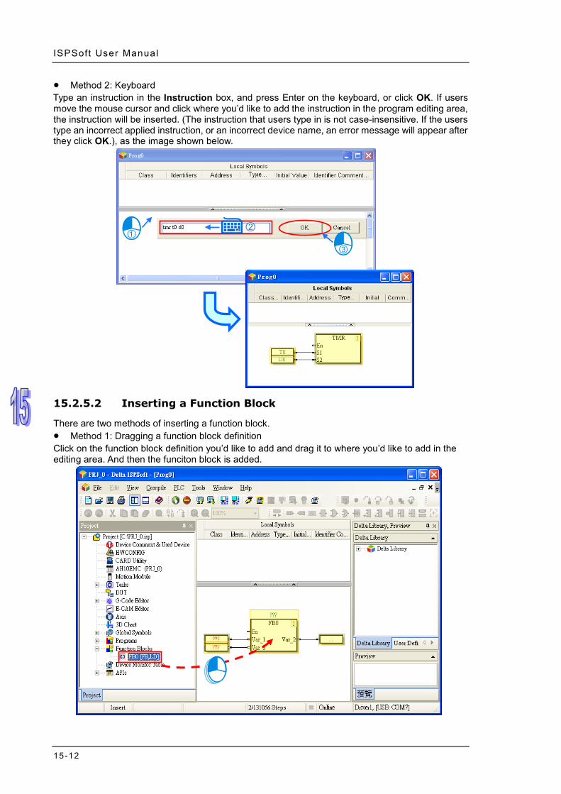
ISPSoft User Manual
15-12
Method 2: Keyboard Type an instruction in the Instruction box, and press Enter on the keyboard, or click OK. If users move the mouse cursor and click where you’d like to add the instruction in the program editing area, the instruction will be inserted. (The instruction that users type in is not case-insensitive. If the users type an incorrect applied instruction, or an incorrect device name, an error message will appear after they click OK.), as the image shown below.
15.2.5.2 Inserting a Function Block
There are two methods of inserting a function block. Method 1: Dragging a function block definition Click on the function block definition you’d like to add and drag it to where you’d like to add in the editing area. And then the funciton block is added.
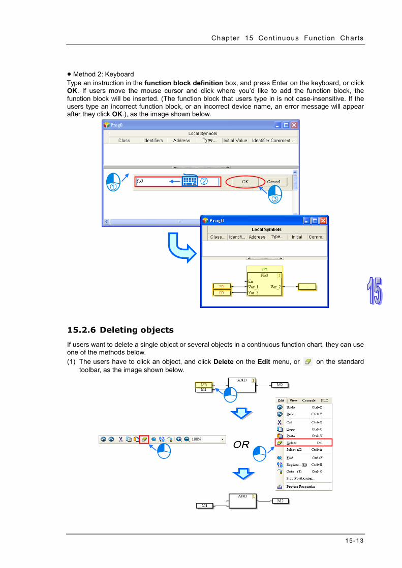
Chapter 15 Cont inuous Funct ion Charts
15-13
Method 2: Keyboard Type an instruction in the function block definition box, and press Enter on the keyboard, or click OK. If users move the mouse cursor and click where you’d like to add the function block, the function block will be inserted. (The function block that users type in is not case-insensitive. If the users type an incorrect function block, or an incorrect device name, an error message will appear after they click OK.), as the image shown below.
15.2.6 Deleting objects
If users want to delete a single object or several objects in a continuous function chart, they can use one of the methods below. (1) The users have to click an object, and click Delete on the Edit menu, or on the standard
toolbar, as the image shown below.

ISPSoft User Manual
15-14
(2) The users have to click to select the object and right-click on the object, and then click Delete on the context menu which appears
(3) The users have to click an object, and press Delete on the keyboard, as the image shown
below.
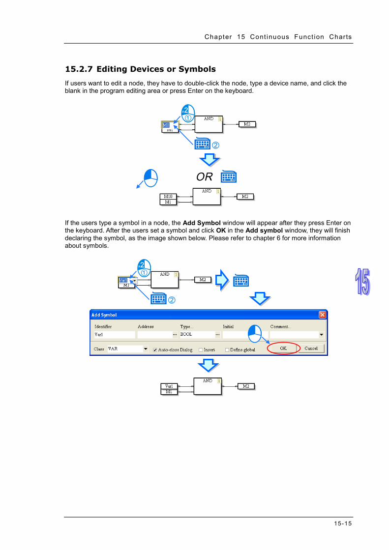
Chapter 15 Cont inuous Funct ion Charts
15-15
15.2.7 Editing Devices or Symbols
If users want to edit a node, they have to double-click the node, type a device name, and click the blank in the program editing area or press Enter on the keyboard.
If the users type a symbol in a node, the Add Symbol window will appear after they press Enter on the keyboard. After the users set a symbol and click OK in the Add symbol window, they will finish declaring the symbol, as the image shown below. Please refer to chapter 6 for more information about symbols.
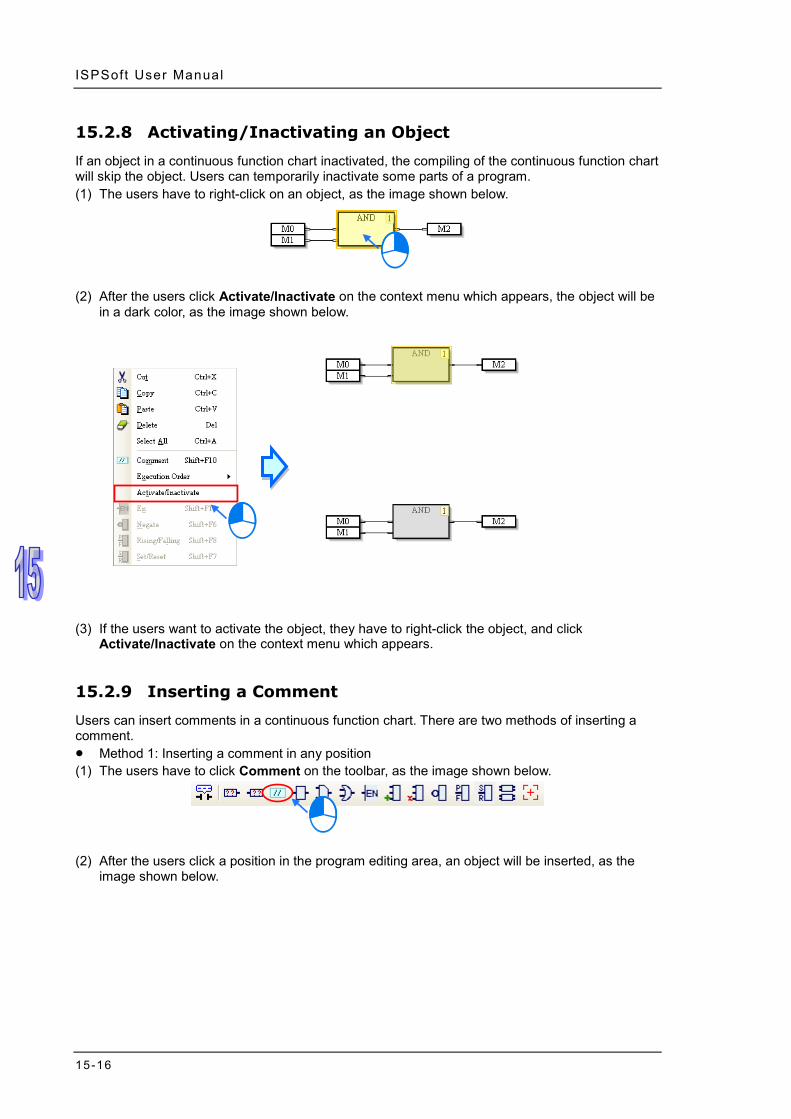
ISPSoft User Manual
15-16
15.2.8 Activating/Inactivating an Object
If an object in a continuous function chart inactivated, the compiling of the continuous function chart will skip the object. Users can temporarily inactivate some parts of a program. (1) The users have to right-click on an object, as the image shown below.
(2) After the users click Activate/Inactivate on the context menu which appears, the object will be
in a dark color, as the image shown below.
(3) If the users want to activate the object, they have to right-click the object, and click
Activate/Inactivate on the context menu which appears.
15.2.9 Inserting a Comment
Users can insert comments in a continuous function chart. There are two methods of inserting a comment. Method 1: Inserting a comment in any position (1) The users have to click Comment on the toolbar, as the image shown below.
(2) After the users click a position in the program editing area, an object will be inserted, as the
image shown below.

Chapter 15 Cont inuous Funct ion Charts
15-17
(3) After the users double-click the object inserted, a box will appear. The users can type a
comment in the box. If the users want to start a new line of text at a specific point, they can press Shift+Enter on the keyboard.
(4) After the users type a comment, they have to click the blank in the program editing window, or
press Enter on the keyboard. This type of comment is independent of the other types of objects in the program editing area. It does not vary with the deletion or the movement of another type of object.
Method 2: Inserting a comment binding with an object (1) The users have to click the object in which a comment will be inserted, as the image shown
below.

ISPSoft User Manual
15-18
(2) After the users click Comment on the toolbar, the comment binding with the object will appear.
The users can edit the comment.
(3) The position of the comment varies with the movement of the object. When the users move the
object, the comment moves, as the image shown below.
15.2.10 Changing the Order in Which Objects are Executed
The numbers in the upper right corners of the objects in a continuous function chart indicate the order in which the objects are executed. If users want to change the number in the upper right

Chapter 15 Cont inuous Funct ion Charts
15-19
corner of an object, they can right-click the object, point to Execution Order on the context menu which appears, and click Up, Down, Front, Back, Insert After, Data Flow, or Topology. If Data Flow is clicked, the order in which the objects in a continuous function chart are executed will be determined by the data flow of the objects. If Topology is clicked, the order in which the objects in a continuous function chart are executed will be determined by the relative positions of the objects.
15.2.11 Displaying/Hiding Information
If users move the mouse cursor to a device or a symbol after they click on the toolbar, the information about the device or the symbol will appear. The information related to a device or a symbol includes a device address and a comment

ISPSoft User Manual
15-20
MEMO

Chapter 16 Auxiliary Editing Tools Table of Contents 16.1 Editing Tools and Auxiliary Functions in ISPSoft .................................16-2
16.1.1 Changing the PLC Type ...............................................................16-2 16.1.2 Downloading/Uploading a Project .................................................16-2 16.1.3 Find/Replace Function in a Ladder Diagram/Function Block Diagram /
Continuous Function Chart ...........................................................16-4 16.1.4 Finding/Replacing Text on an Instruction List/in an Structured Text …………………………………………………………………………..16-6 16.1.5 Finding/Replacing a Step or a Transition in a Sequential Function
Chart (SFC) ..................................................................................16-8 16.1.6 Finding an Identifier in a Symbol Table .......................................16-10 16.1.7 Finding/Replacing a Device or a Symbol in a Project ................. 16-11 16.1.8 Printing Function .........................................................................16-12
16.2 Managing Devices and Registers ......................................................16-15 16.2.1 Device Comment List for a DVP Series PLC ..............................16-15 16.2.2 Report on the Devices Used in a DVP Series PLC .....................16-17 16.2.3 Managing Devices in an AH/AS Series CPU Module .................16-19 16.2.4 Editing Register Memory ............................................................16-24 16.2.5 Editing Bit Memory ......................................................................16-30 16.2.6 Editing the Values in the File Registers in a DVP Series PLC ....16-34
16.3 Step Positioning .................................................................................16-41 16.3.1 Using Step Positioning ................................................................16-41
16.4 Program Comparison .........................................................................16-41 16.4.1 Introduction to Program Comparison ..........................................16-41 16.4.2 Compare with File .......................................................................16-42 16.4.3 Compare with PLC ......................................................................16-43

ISPSoft User Manual
16-2
16.1 Editing Tools and Auxiliary Functions in ISPSoft
16.1.1 Changing the PLC Type
Users are allowed to change the PLC type in ISPSoft. Users have to pay attention to the following two points before they change the PLC type. (a) An AH/AS and DVP system are not compatible with each other, and therefore users cannot
exchange the modules among an AH/AS series CPU module, and an DVP series PLC. (b) If the PLC type is changed, the functions, the range of devices, and the instructions supported
may be changed. After the PLC type is changed, users have to check whether the original program, parameter setting, hardware configuration, and network configuration can make the system operate normally.
If users want to change the PLC type, they can click Change PLC Type… on the Tools menu, select a PLC type in the Change PLC Type window, and click OK.
16.1.2 Downloading/Uploading a Project
Users can download/upload not only the program in a project, but also the functions or the parameters in the project. If users want to download the project, they can click the PLC menu, point to Transfer, and click Download. Or click on the toolbar. After that users will see a PC=>PLC (Download) window, select the items you’d like to download and then click Transfer.

Chapter 16 Aux i l iary Edit ing Tools
16-3
If users want to download the project, they can click the PLC menu, point to Transfer, and click Upload. Or click on the toolbar. After that users will see a PC=>PLC (Upload) window, select the items you’d like to upload and then click Transfer.
The items in the upload and download windows vary according to different series. Not editable items will be grayed out. The descriptions of the items in the upload/download window are as follows.
Transfer selection Description
Object Code Object code is what a computer compiler produces. (The item must be selected.)
Program Program (Source code) that users create Project/POU/Section/Symbol Comments Comments added to the project
Synchronize Project and PLC Password
During the transmission of the project, the project password and the PLC password become the same.
Retentive Range Range of latched devices (The item in the Transfer Setup window for the downloading/uploading of a project for an AH series CPU module cannot be selected.)
Initial Value When the project is downloaded, the initial values of the symbols are written into the corresponding memories in the PLC. Refer to section 6.2.6.
RTC When the project is downloaded, the date and the time on the computer’s clock is written into the real-time clock in the PLC.
Position Planning Table Refer to chapter 22. Axis Table Refer to chapter 9. G-Code Refer to chapter 21. E-CAM Refer to chapter 21.
Additional remark (a) Please refer to section 18.3 for more information about project passwords and PLC passwords. (b) The range of latched devices in an AH/AS series CPU module is downloaded/uploaded through
HWCONFIG. Please refer to chapter 3 for more information.

ISPSoft User Manual
16-4
16.1.3 Find/Replace Function in a Ladder Diagram/Function Block Diagram / Continuous Function Chart
The Find/Replace function that ISPSoft provides varies with the program editing window. This section aims at describing the functions used in the window in which a ladder diagram / function block diagram / continuous function chart can be created. Users can open a program editing window, and click the position in the working area at which they want to start searching. (For searching in the CFC, click anywhere blank.) If the users click the local symbol table in the program editing window, the local symbol table will be searched. Please refer to section 16.1.6 for more information about using the Find function in a symbol table.
In the editing environment in which a ladder diagram / function block diagram / continuous function chart can be created, the Find item, and the Replace item are on the Edit menu. The icons corresponding to these items are on the toolbar in the editing environment. The same window is opened, whether users click Find or Replace. The page displayed in the window opened varies with the item clicked. There are three tabs in the window opened.

Chapter 16 Aux i l iary Edit ing Tools
16-5
The Find and the Replace page are shown below. Type the object which will be searched for, and select search conditions. The users can do a search on the object typed in the Find box by clicking Find Next (F3) or pressing F3 on the keyboard. The users can still do a search on the object typed in the Find box by means of pressing F3 on the keyboard even when the Find/Replace/Goto window is closed. When not selecting the scope, the search will only focus on the current editing. When the Project is selected in the Scope section, the results will be shown.
Search
condition Description
Find Users can type the object which will be searched for, or select an object which has been searched for after they click in the box.
Direction Users can search down or search up.
Options
Match Case: ISPSoft searches only for words that match the case of the word that users type in the Find box.
Whole Words: Whole Words instructs ISPSoft to find complete words only, and not to find words that only contain what users type. If the option is selected, users can further select the “Copy Comments to Replace Devices (Whole Words)” to copy the source device comments to the target device comments.
Origin Current Network: The search starts at the position selected. Entire Scope: The search starts at the beginning of the program or the end of
the program. This is the only option for CFC. Scope Users can select ranges which will be searched.
The users can type a replacement object in the Replace with box, or select a replacement object which has been typed after they click in the box. If the users click Replace, an occurrence of the object typed in the Find box will be replaced by the replacement object. If users click Replace All, all the occurrences of the object typed in the Find box will be replaced. If the users want to go to a specific position in the LD and FBD program, they can click the Goto tab in the Find/Replace/Goto window, select Network Label or Bookmark in the Location Type drop-down list box, select an item in the Index drop-down list box, and click Goto (GOto function is not available for CFC).

ISPSoft User Manual
16-6
16.1.4 Finding/Replacing Text on an Instruction List/in an Structured Text
Users can only find and replace text on an instruction list/in a structured text. The functions described in this section are used in the present program editing window. Users can open a program editing window, and click the position in the working area at which they want to start searching. If the users click the local symbol table in the program editing window, the local symbol table will be searched. Please refer to section 16.1.6 for more information about using the Find function in a symbol table.
After the users click Find on the Edit menu, or on the toolbar, the Search/Replace Text window will appear.
After the users click Replace on the Edit menu, or on the toolbar, the Search/Replace Text window will appear.

Chapter 16 Aux i l iary Edit ing Tools
16-7
The Find page and the Replace page are shown below. Type the object which will be searched for, and select search conditions. If the users want to use the Replace function, they have to type a replacement object in the Replace with box. The users can do a search on the object typed in the Search for box by clicking Find Next (F3) or pressing F3 on the keyboard. The users can still do a search on the object typed in the Search for box by means of pressing F3 on the keyboard even if the Find/Replace/Goto window is closed.
Search condition Description
Search for Users can type the object which will be searched for, or select an object which has been searched for after they click in the box.
Case sensitivity ISPSoft searches only for words that match the case of the word that users type in the Search for box.
Whole words only Whole words only instructs ISPSoft to find complete words only, and not to find words that only contain what users type.
Search from caret The search starts at the text cursor. (If this checkbox is not selected, the system will search the whole program.)
Selected text only The search starts at the text selected. (If this checkbox is not selected, the system will search the whole program.)
Regular expression After this checkbox is selected, regular expressions can be used. Direction Users can search down or search up.
* A regular expression is a type of standard syntax. For example, “*” is a wildcard. Please refer to related technical documents for more information.
If the users use the Replace function, the Confirm replace window will appear after an object meeting the search conditions selected is found.

ISPSoft User Manual
16-8
Button Function
Yes The object found is replaced by the replacement object, and the system searches for the next occurrence of the object typed in the Search for box.
No The object found is not replaced by the replacement object, and the system searches for the next occurrence of the object typed in the Search for box.
Cancel The search is canceled, and the Confirm replace window is closed,
Yes to all All the objects meeting the search conditions selected are replaced by the replacement object.
16.1.5 Finding/Replacing a Step or a Transition in a Sequential
Function Chart (SFC) Users can only use the Find function and the Replace function in a sequential function chart (SFC). Users can open a program editing window, and click the position in the working area at which they want to start searching. If the users click the local symbol table in the program editing window, the local symbol table will be searched. Please refer to section 16.1.6 for more information about using the Find function in a symbol table.
In the editing environment in which a sequential function chart can be created, the Find item and the Replace item are on the Edit menu. The icons corresponding to these items are on the toolbar in the editing environment. The same window is opened, whether users click Find or Replace. The page displayed in the window opened varies with the item clicked. There are two tabs in the window opened.

Chapter 16 Aux i l iary Edit ing Tools
16-9
The Find page and the Replace page are shown below. Type the object which will be searched for, and select search conditions. The users can do a search on the object typed in the Find box by clicking Find Next (F3) or pressing F3 on the keyboard. The users can still do a search on the object typed in the Find box by means of pressing F3 on the keyboard even if the Find/Replace/Goto window is closed. When not selecting the scope, the search will only focus on the Steps and Transitions in the SFC. As for the programs in the Actions and Transitions, users will have to open the window and refer to the section 16.1.3 and 16.1.4 to edit the program. When the Project is selected in the Scope section, the results will be shown.
Search condition Description
Find Users can type the object which will be searched for, or select an object which has been searched for after they click in the box.
Direction Users can search down or search up.
Options
Match Case: ISPSoft searches only for words that match the case of the word that users type in the Find box.
Whole Words: Whole Words instructs ISPSoft to find complete words only, and not to find words that only contain what users type. If the option is selected, users can further select the “Copy Comments to Replace Devices (Whole Words)” to copy the source device comments to the target device comments.
Scope Users can select ranges which will be searched.

ISPSoft User Manual
16-10
The users can type a replacement object in the Replace with box, or select a replacement object which has been typed after they click in the box. If the users click Replace, an occurrence of the object typed in the Find box will be replaced by the replacement object. If users click Replace All, all the occurrences of the object typed in the Find box will be replaced.
16.1.6 Finding an Identifier in a Symbol Table
Users can only use the Find function in a local symbol table/global symbol table. They can not use the Replace function and the Goto function in a local symbol table/global symbol table. Besides, only the identifiers in a local symbol table/global symbol table can be searched for. The function described in this section is used in the present program editing window, and is not used in the whole project. Users can open an editing window, and click the position in the symbol table at which they want to start searching. If the users click the working area in a program editing window, working area will be searched. Please refer to section 16.1.3~section 16.1.5 for more information about using the Find/Replace function in a working area.
After the users click Find on the Edit menu, or on the toolbar, the Search/Replace/Goto window will appear.

Chapter 16 Aux i l iary Edit ing Tools
16-11
The users can do a search on the object typed in the Find box by clicking Find Next (F3) or pressing F3 on the keyboard. The users can still do a search on the object typed in the Find box by means of pressing F3 on the keyboard even if the Find/Replace/Goto window is closed. Search condition Description
Find Users can type the object which will be searched for, or select an object which has been searched for after they click in the box.
Direction Users can search down or search up.
Options
Match Case: ISPSoft searches only for words that match the case of the word that users type in the Find box. Whole Words: Whole Words instructs ISPSoft to find complete words only, and not to find words that only contain what users type.
16.1.7 Finding/Replacing a Device or a Symbol in a Project
The Find/Replace function is used to search for/replace a device or a symbol in a project. The global symbol, the local symbol tables in the POUs, and the working areas in the project are searched. If there is a group of projects, the Find/Replace function is used in the project which is being edited. Right-click the Global Symbols/Programs/Function Blocks in the project management area, and then click Find/Replace in Project on the context menu.
The Find page and the Replace page are shown below. There are two tabs in the Find/Replace in Project window. Type the object which will be searched for, and select search conditions. If the users click OK on the Find page, the system will use the Find function. If the users click OK on the

ISPSoft User Manual
16-12
Replace page, all the occurrences of the object typed in the Search for box will be replaced by the replacement object. The replacement can not be undone.
After the users use the Find/Replace function, the search results will be displayed in the message display area at the bottom of the ISPSoft window. If the users double-click a search result, the system will lead the users to the position of the object corresponding to the search result.
16.1.8 Printing Function
ISPSoft provides a printing function. Printer Setup
After users click Printer Setup on the File menu, the Print Setup window will be opened. Before a document is printed, the users can select a printer, and set a print format.
Project Print
After users click Project Print on the File menu, users can select items which will be printed in the Project Print window. The items which can be selected are the main programs, the function blocks, and the global symbols.

Chapter 16 Aux i l iary Edit ing Tools
16-13
An example of a print result is shown below. The contents which are printed include a local symbol table. If there are comments in the window whose contents are printed, the comments will be printed.
If users want to print the contents of the present window, they can click Print on the File menu or on the toolbar. The users can set a print range in the Print Setup window. The print result
varies with the contents of the present window. Please refer to the table below for more information.

ISPSoft User Manual
16-14
Window All Part
Global symbol table The complete global symbol table is printed.
Users can not print a part of the global symbol table.
Ladder diagram/Function block diagram
The complete program and local symbol table are printed.
The complete local symbol table and a part of the program are printed. (The start number and the end number are network numbers.)
Instruction list/Structured text
The complete program and local symbol table are printed.
The complete local symbol table and a part of the program are printed. (The start number and the end number are network numbers.)
Sequential function chart
The complete local symbol table and sequential function chart are printed. (The actions and the transitions are not printed.)
Users can not print a part of the sequential function chart.
Continuous function chart
The complete program and local symbol table are printed.
Users can not print a part of the continuous function chart.
*.After users open the window for an action/transition, they can print the action/transition.
After the users click Preview in the Print Setup window, the Print Preview window will be opened. Please refer to appendix C for more information about the print management tool that ISPSoft provides.

Chapter 16 Aux i l iary Edit ing Tools
16-15
16.2 Managing Devices and Registers
16.2.1 Device Comment List for a DVP Series PLC
If users want to export the device comment list from a project for a DVP series PLC, they can click the File menu, point to Export, and click Export Device Comments…. If the users want to import the device comment list, they can click the File menu, point to Import, and click Import Device Comments….
If the users want to manage the comments on devices, they can click Device Comment List on the View menu, or double-click Device Comment List in the project management area. After the users click Device Comment List on the View menu, or double-click Device Comment List in the project management area, the system will open the Device Comment List window.
The comments on devices are on a View/Edit page. After the users click a tab which indicates a device type in the window, the comments on devices are displayed. The mark “*” at the left side of a device indicates that the device is used in the program. If the users want to make a comment on a device, they can double-click the Comment cell for the device, and type the comment.
The devices on which comments are made and all the comments on the devices are on the Used

ISPSoft User Manual
16-16
Device Comment page. After the users double-click the Comment cell for a device, they can edit the comment on the device.
*1. The comments on devices are separate from the comments on symbols. The comments on devices appear in the
Device Comment List window, while the comments on symbols do not appear in the Device Comment List window.
*2. Users can edit the default comments on the special relays and the special registers in a project. However, the new comments are valid only in this project.
After the uses right-click the table in the Device Comment List window, a context menu will appear. The context menu comprises basic items and special items.
Jump to…
After the users click Jump to… on the context menu, the Jump to… window will appear. The users can type a device name in the Device Name box. After the users click OK in the Jump to… window, they can easily view the device name and the comment on the device on a View/Edit page. The device name typed must be matched with the device type clicked, otherwise, the device name will not be found. If the users click Jump to… on the context menu which appears after they right-click the Used Device Comment page, the device name typed in the Device Name box in the Jump to… window must be on the Used Device Comment page.
Delete Unused Device Comment
After the users click Delete Unused Device Comment on the context menu, the system will

Chapter 16 Aux i l iary Edit ing Tools
16-17
delete the comments on the devices which are not used in the program.
Copy with Device Name
If the users click Cut/Copy on the context menu, the items selected in the Device Comment List window will be cut/copied to the Windows Clipboard. The items cut/copied can be pasted into a document in Microsoft Excel. If Copy with Device Name on the context menu is clicked before Cut/Copy on the context menu is clicked, the contents which will be cut/copied will include device names. Please compare the two Excel tables below.
Assign Device Comment to Symbol
If symbols are assigned devices, the comments on the devices will be assigned to the symbols after the users click Assign Device Comment to Symbol on the context menu.
16.2.2 Report on the Devices Used in a DVP Series PLC
When users edit a project for a DVP series PLC, they can refer to the report on the devices used in

ISPSoft User Manual
16-18
the project. However, the users have to compile the program in the project before they refer to the report on the devices used in the project. Besides, if the users modify the program after the window for the report is opened, they have to close the window, compile the new program, and open the window again to get the latest information. If users click Used Device Report on the View menu, or double-click Used Device Report in the project management area, the Used Device Report window will be opened.
The Used Device Report window is composed of two parts. A table of devices is in the left part of the window. The users can click the tabs at the top of the window. The checks in the cells for devices indicate that the devices are used in the program. For example, there are checks in the cells for M11 and M12.
A table of devices used in the program is in the right part of the window. The devices listed are not classified. If a certain device is used in different positions in the program, the information about the positions will be listed. For example, M11 in the figure below is used in two positions in the program.

Chapter 16 Aux i l iary Edit ing Tools
16-19
After the users double-click a row in the right part of the window, the system will lead the users to the position corresponding to the row.
If the users press Enter on the keyboard after they type a device number in the Go to… box, the blue cursor in the table in the left part of the window will move to the position corresponding to the device number.
16.2.3 Managing Devices in an AH/AS Series CPU Module
Users can manage the devices in an AH/AS series CPU module. After users click Device Comment _ Used Device on the View menu, or double-click Device Comment & Used Device in the project management area, the Device Comment & Used Device window will be opened. There are two tabs at the top of the Device Comment & Used Device window. If the users modify the program or comments after the window is opened, they have to close the window, compile the

ISPSoft User Manual
16-20
new program, and open the window again to get the latest information.
The devices on which comments are made and the comments on the devices are on the View/Edit Device Comment pages. The tabs in the window indicate device types. After the users click All, the devices on which comments are made are displayed. Besides, the mark “*” at the left side of a device indicates that the device is used in the program.
The users can modify the comments on the View/Edit Device Comment page, and add comments to a View/Edit Device Comment page. If the users want to modify the comment on a device, they can double-click the comment, and modify the comment in the Input/Modify Device Comment window. The users can also modify the comment on a device by right-clicking the comment, clicking Edit on the context menu, and modifying the comment in the Input/Modify Device Comment window. The users can edit the default comments on the SR devices and the SM devices in a project. However, the new comments are valid only in this project.

Chapter 16 Aux i l iary Edit ing Tools
16-21
If the users want to add a comment to a View/Edit Device Comment page, they can right-click the View/Edit Device Comment page, click Add on the context menu, and type a device name and a comment in the Input/Modify Device Comment window. The users can also add a comment to a View/Edit Device Comment page by typing a device name directly, and typing a comment in the Input/Modify Device Comment window which appears.
If the users want to delete the comment on a device on a View/Edit Device Comment page, they can select the comment, right-click the comment, and click Delete on the context menu. If the users want to delete a range of comments on a View/Edit Device Comment page, they can select the first comment and the last comment while they press Shift on the keyboard, right-click a comment selected, and click Delete on the context menu. If the users want to delete all the comments on a View/Edit Device Comment page, they can right-click the page, select Select All on the context menu, right-click a comment selected, and click Delete on the context menu.

ISPSoft User Manual
16-22
The users can also delete the device selected or the devices selected by pressing Delete on the keyboard. If the comments deleted include the comments on SM devices or the comments on SR devices, the comments on the SR devices or the comments on the SR devices will be recovered.
If the users want to rearrange the devices on a View/Edit Device Comment page, they can right-click the page, and click Sort on the context menu.
The users can export the comments on devices as a CSV file, edit the CSV file through Microsoft Excel, and import the new CSV file into ISPSoft. If the default comments on SM/SR devices are modified, the comments exported will include the new comments on theses SM/SR devices. The comments exported do not include the default comments on all the SM/SR devices. If the comments imported include the comments on SM/SR devices, the default comments on these SM/SR devices will be modified after the comments are imported, and the default comments on the remaining SM/SR devices will not be changed after the comments are imported. If the users want to export the comments on devices, they can right-click a View/Edit Device Comment page, click Export on the context menu, select a folder in the Save in drop-down list box in the Export Device Comments window, type a filename in the File name box, and click Save. If the users want to import a CSV file, they can right-click a View/Edit Device Comment page, click Import on the context menu, select the CSV file in the Import Device Comments window, and click Open.

Chapter 16 Aux i l iary Edit ing Tools
16-23
For a quick way to go to the specific device range, right-click on the Device Comment area to see the context menu and select “Jump to”. After that a Jump to window will show up. Type the device name and press OK. The table will display the required device range. Before typing the device name, you will need to make sure the device name you are going to type exists in the table. You can also use Jump to function in the Used Device tab.
The devices used in the program and the information about the devices are on the Used Device pages. The tabs in the window indicate device types. Besides, after the users double-click a row on a Used Device page, the system will lead the users to the position corresponding to the row.

ISPSoft User Manual
16-24
16.2.4 Editing Register Memory
Users can edit the values in the T/C/D/L devices in a batch. And the new values in these T/C/D/L devices can be saved and downloaded. After users create a project, they can click Edit Register Memory on the PLC menu to open the Edit Register Memory window.
The values in the tables in the Edit Register Memory window are not the values uploaded form the PLC. They are the values saved last time. If the Edit Register Memory window in the project is opened for the first time, the default values in the tables are 0. The tabs at the top of the Edit Register Memory window indicate device types.

Chapter 16 Aux i l iary Edit ing Tools
16-25
If the users want to edit the value in the cell for a device, they can click the cell for the device, and type a value.
The users can select a data format in the Data Format section.
The users can select the 16 bits option button or the 32 bits option button in the Data Length section. If the 32 bits option button is selected, the value in the cell for a device includes the value in the next device. Take the figures below for example. The hexadecimal value in D0 is AAAA, the hexadecimal value in D1 is BBBB, and the hexadecimal value in D2 is CCCC. If the 32 bits option button in the Data Length section is selected, the value in the cell for D0 will include the value in D1, the value in the cell for D1 will include the value in D2, and the value in the cell for D2 will include the value in D3. In other words, if the 32 bits option button is selected, the value in the cell for D0 will become BBBBAAAA, the value in the cell for D1 will become CCCCBBBB, and the value in the cell for D2 will become CCCC.
If the users click Clear All, the values on the present page will be cleared to 0, and the values on the other pages will remain unchanged.

ISPSoft User Manual
16-26
Besides, the users can clear the values on the present page by right-clicking the present page, clicking Select All on the context menu, right-clicking the present page again, clicking Clear as 0 on the context menu.
If the users want to clear the values in the cells for a range of devices on the present page, they can drag across the cells, right-click the present page, and click Clear as 0 on the context menu.
After type the device number in the Go to field, click Go. The blue cursor will move to the number you have typed.
After the users click Transfer, the Transfer Setup window will appear. The users can download the values in the tables to the PLC, or upload the values in the T/C/D devices from the PLC through the

Chapter 16 Aux i l iary Edit ing Tools
16-27
window. Before Transfer is clicked, the users have to make sure that ISPSoft is connected to the PLC normally. Please refer to section 2.4 for more information. The users can select the Read from PLC Device Register option button or the Write to PLC Device Register option button. Besides, the users can select device ranges. The values in the devices which are not in the device ranges will remain unchanged after OK is clicked. After the setting is complete, the users can click OK. After OK is clicked, the values in the T devices, the values in the C devices, and the values in the D devices which are in the device ranges set will be transferred.
Before the values are written into the registers, users have to make sure that the operation does not affect the system, or cause damage to the system and staff.
The values in the Edit Register Memory window can be saved with the project. If the present window is the Edit Register Memory window, the values in the Edit Register Memory window will be saved as a .dvl file whose primary filename is the project name in the folder in which the project (*.isp) is saved after the users click Save on the File menu or the toolbar. If the users want to open the Edit Register Memory window in the project again, the system will open the dvl file in the folder in which the project (*.isp) is saved. If no dvl is in the folder in which the project is saved, the values in the Edit Register Memory window will be 0. Besides, the users can save the values in the Edit Register Memory window as a dvl file in another folder after they click Save As on the File menu. If the users want to open the dvl file which was saved previously, they can click Open on the File menu or the toolbar.

ISPSoft User Manual
16-28
The users can export the values on the present page as a CSV file, and edit the CSV file through Microsoft Excel. If the users want to export the values on the present page, they can right-click the present page, select the range you’d like to export and then click Export on the context menu. Select a folder in the Save in drop-down list box in the Save As window, type a filename in the File name box, and click Save. The contents exported are the contents of the page selected.
If the users want to import a CSV file into a page, they can right-click the page, click Import on the context menu, select the CSV file in the Open window, and click Open. The file imported must be matched with the device type clicked.
After the users click Hint in the Edit Register Memory window, the ISPSoft window will appear. After a hint is typed in the ISPSoft window, the hint will appear at the bottom of the Edit Register Memory window. The hint is saved with the values in the Edit Register Memory window. After the users open a dvl file, they can identify the tables in the file through the hint in the file.

Chapter 16 Aux i l iary Edit ing Tools
16-29
If the present window is the Edit Register Memory window, the users can print the present page in the Edit Register Memory window by clicking Print on the File menu or on the toolbar.

ISPSoft User Manual
16-30
Select the All option button or the Part option button in the Print Options section, set margins, and select items which will be added. After the users click Printer Setup, they can select a printer, and set a print format. After the users click Preview, they can preview the document which will be printed. After the setting is complete, the users can click Print in the Preview window.
16.2.5 Editing Bit Memory
Users can edit the states of several M/S devices in a batch. The new states of these M/S devices can be saved and downloaded. After users create a project, they can click Edit Bit Memory (M, S) on the PLC menu to open the Edit Bit Memory window.
The states in the tables in the Edit Bit Memory window are not the states uploaded form the PLC. They are the states saved last time. If the Edit Bit Memory window in the project is opened for the first time, the default states in the tables are OFF. The tabs at the top of the Edit Bit Memory window indicate device types.
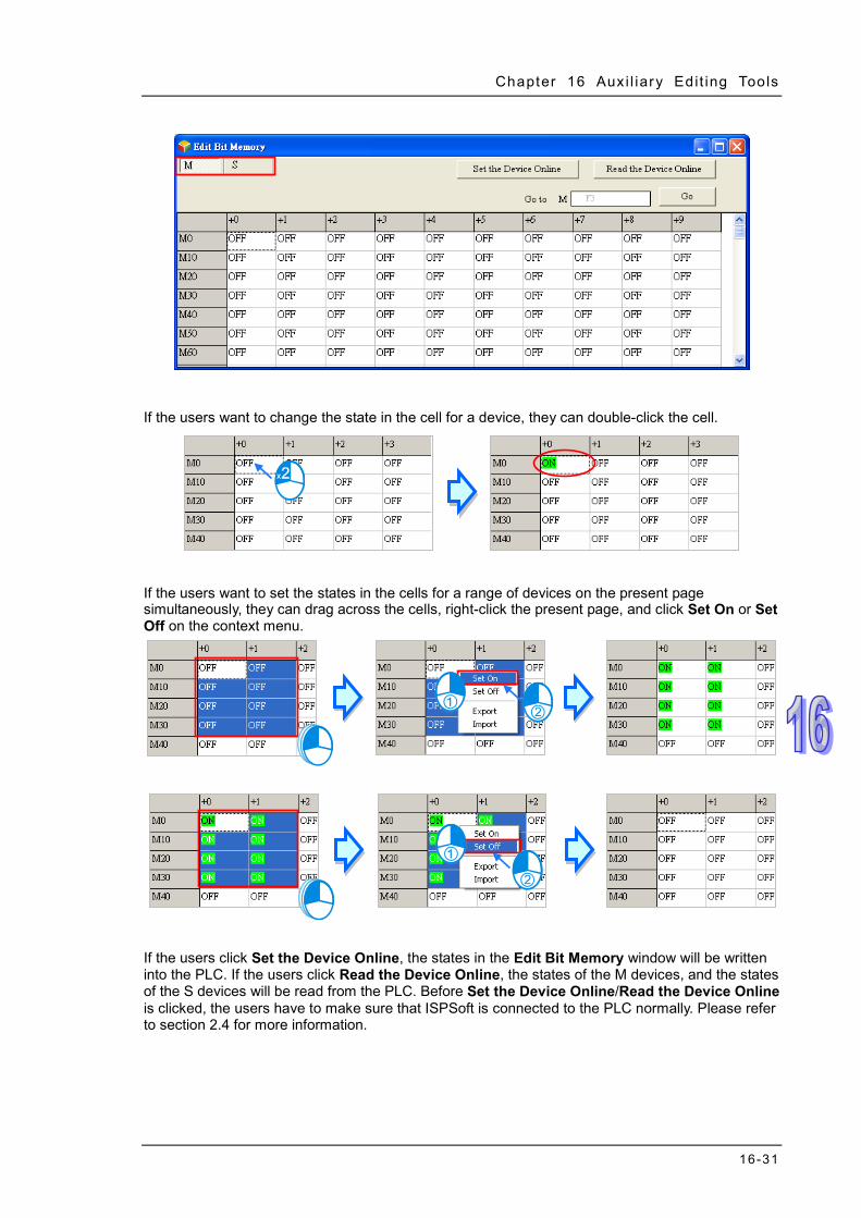
Chapter 16 Aux i l iary Edit ing Tools
16-31
If the users want to change the state in the cell for a device, they can double-click the cell.
If the users want to set the states in the cells for a range of devices on the present page simultaneously, they can drag across the cells, right-click the present page, and click Set On or Set Off on the context menu.
If the users click Set the Device Online, the states in the Edit Bit Memory window will be written into the PLC. If the users click Read the Device Online, the states of the M devices, and the states of the S devices will be read from the PLC. Before Set the Device Online/Read the Device Online is clicked, the users have to make sure that ISPSoft is connected to the PLC normally. Please refer to section 2.4 for more information.

ISPSoft User Manual
16-32
Before the states are written into the PLC, users have to make sure that the operation does not affect the system, or cause damage to the system and staff.
The users can export the states on the present page as a CSV file, and edit the CSV file through Microsoft Excel. If the users want to export the states on the present page, they can right-click the present page, select the range you’d like to export and then click Export on the context menu. Select a folder in the Save in drop-down list box in the Save As window, type a filename in the File name box, and click Save. The contents exported are the contents of the page selected.
If the users want to import a CSV file into a page, they can right-click the page, click Import on the context menu, select the CSV file in the Open window, and click Open. The file imported must be matched with the device type clicked.
The states in the Edit Bit Memory window can be saved with the project. If the present window is the Edit Bit Memory window, the states in the Edit Bit Memory window will be saved as a dvb file whose primary filename is the project name in the folder in which the project (*.isp) is saved after the users click Save on the File menu or the toolbar. If the users want to open the Edit bit Memory window in the project again, the system will open the dvb file in the folder in which the project (*.isp) is saved. If no dvb is in the folder in which the project is saved, the states of the devices in the Edit Bit Memory window will be OFF Besides, the users can save the states in the Edit Bit Memory window as a dvb file in another folder after they click Save As on the File menu. If the users want to open the dvb file which was saved previously, they can click Open on the File menu or the toolbar.

Chapter 16 Aux i l iary Edit ing Tools
16-33
If the present window is the Edit Bit Memory window, the users can print the present page in the Edit Bit Memory window by clicking Print on the File menu or on the toolbar.
Select the All option button or the Part option button in the Print Options section, set margins, and select items which will be added. After the users click Printer Setup, they can select a printer, and set a print format. After the users click Preview, they can preview the document which will be printed. After the setting is complete, the users can click Print in the Preview window.

ISPSoft User Manual
16-34
16.2.6 Editing the Values in the File Registers in a DVP Series PLC
Users can edit the values in several file registers in a DVP series PLC at a time. The new values in these file registers can be saved and downloaded. After users create a project for a DVP series PLC, they can click Edit File Register Memory on the PLC menu to open the Edit File Register Memory window.
The values in the table in the Edit File Register Memory window are not the values uploaded form the PLC. They are the values saved last time. If the Edit File Register Memory window in the project is opened for the first time, the default values in the table are 0. Users can select different tap for different register ranges.
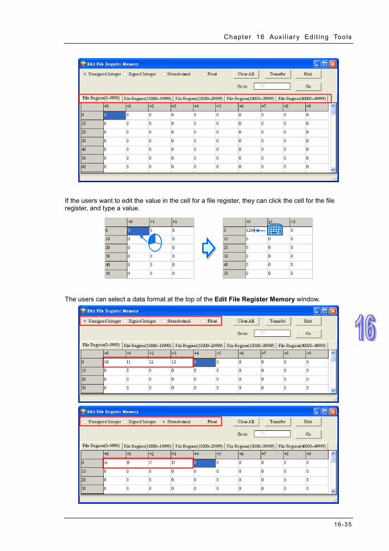
Chapter 16 Aux i l iary Edit ing Tools
16-35
If the users want to edit the value in the cell for a file register, they can click the cell for the file register, and type a value.
The users can select a data format at the top of the Edit File Register Memory window.

ISPSoft User Manual
16-36
If the users click Clear All, the values in the Edit File Register Memory window will be cleared to 0.
Besides, the users can clear the values on the present page by right-clicking the present page, clicking Select All on the context menu, right-clicking the present page again, clicking Clear as 0 on the context menu.
If the users want to clear the values in the cells for a range of file registers on the present page, they can drag across the cells, right-click the present page, and click Clear as 0 on the context menu.

Chapter 16 Aux i l iary Edit ing Tools
16-37
After the users click Transfer, the Transfer Setup window will appear. The users can download the values in the table to the PLC, or upload the values in the file registers from the PLC through the window. Before Transfer is clicked, the users have to make sure that ISPSoft is connected to the PLC normally. Please refer to section 2.4 for more information. Select Read form PLC or Write to PLC in the Transmission Type drop-down list box, and then select the All option button or the Part option button. After the setting is complete, the users can click OK.
Before the values are written into the registers, users have to make sure that the operation does not affect the system, or cause damage to the system and staff.
The values in the Edit File Register Memory window can be saved with the project. If the present window is the Edit File Register Memory window, the values in the Edit Register Memory window will be saved as a wft file whose primary filename is the project name in the folder in which the project (*.isp) is saved after the users click Save on the File menu or the toolbar. If the users want to open the Edit File Register Memory window in the project again, the system will open the wft file in the folder in which the project (*.isp) is saved. If no wft is in the folder in which the project is saved, the values in the Edit File Register Memory window will be 0. Besides, the users can save the values in the Edit File Register Memory window as a wft file in another folder after they click Save As on the File menu. If the users want to open the wft file which was saved previously, they can click Open on the File menu or the toolbar.

ISPSoft User Manual
16-38
The users can export the values on the present page as a CSV file, and edit the CSV file through Microsoft Excel. If the users want to export the values on the present page, they can right-click the present page, click Export on the context menu, select a folder in the Save in drop-down list box in the Save As window, type a filename in the File name box, and click Save.
If the users want to import a CSV file into the page, they can right-click the page, click Import on the context menu, select the CSV file in the Open window, and click Open.

Chapter 16 Aux i l iary Edit ing Tools
16-39
After the users click Hint in the Edit File Register Memory window, the ISPSoft window will appear. After a hint is typed in the ISPSoft window, the hint will appear at the bottom of the Edit File Register Memory window. The hint is saved with the values in the Edit File Register Memory window. After the users open a wft file, they can identify the table in the file through the hint in the file.
If the present window is the Edit File Register Memory window, the users can print the present

ISPSoft User Manual
16-40
page in the Edit File Register Memory window by clicking Print on the File menu or on the toolbar.
Select the All option button or the Part option button in the Print Options section, set margins, and select items which will be added. After the users click Printer Setup, they can select a printer, and set a print format. After the users click Preview, they can preview the document which will be printed. After the setting is complete, the users can click Print in the Preview window.

Chapter 16 Aux i l iary Edit ing Tools
16-41
16.3 Step Positioning
16.3.1 Using Step Positioning When an error occurred during operation, users can use special registers (e.g. SR1, SR2, the 32 bit registers for storing wrong addresses in the AH series) to know which step went wrong and then go to the specific program to check and fix it. Go to Edit > Step Positioning to open the Step Positioning window. Type the step number you’d like to inquire and press OK. The system will direct you to the corresponding POU and the position of the step in the program, as the image shown below. Be sure to program the project before using the step positioning function.
16.4 Program Comparison
16.4.1 Introduction to Program Comparison ISPSoft provides a program comparison tool for users to compare 2 ISPSoft projects, or to compare an ISPSoft project and the PLC internal programs. Here are the comparison rules. Comparison items include product series, models, POUs, global symbols, local symbols and programs. For a POU comparison, the name of a POU will be checked first. Different POU name will be seen as different, even for those with the same contents. For a variable symbol comparison, the order of a variable symbol will be checked first. Different variable symbol order will be seen as different, even for those with the same contents. As the image shown below, the var_a and var_b from the left and right are with different order; thus they will be seen as different.

ISPSoft User Manual
16-42
The comparison of variable symbols will include the step skipping in the program. As the image shown below the var_c only appears on the left and that does not exist on the right.
The comparison of POUs in the languages of LD, FBD, IL, ST will include the step skipping in the program. As the image shown below, the second line on the left does not exist on the right.
Once there is a difference in the SFC, the comparison of POUs in the language of SFC will be seen as different. When the Action and Transition are different in the SFC, the system will identify which sections or lines of action/transition are different. Projects should be saved before running the program comparison tool. Be sure to select the program items while downloading the CPU module; so that the programs in the CPU module can be compared.
16.4.2 Compare with File
It is used to compare different projects in the computer. Select File > Program Comparison > Compare with File, and then the Open Project window will appear. Select the project you’d like to compare with and click Open.
After that you will see a program comparison table, listing the sameness and the differences.

Chapter 16 Aux i l iary Edit ing Tools
16-43
The location of the current project
The location of the compared project
The comparison results, including models, global symbols and program contents. Double click the items with different comparison results; the system will open the contents for users to review. As the image shown below, click Prog0, the item with a different comparison result, to show its contents.
16.4.3 Compare with PLC
It is used to compare the CPU module contents and the projects in the computer. Make sure the connection between ISPSoft and the CPU module has been established. Refer to section 2.4 for
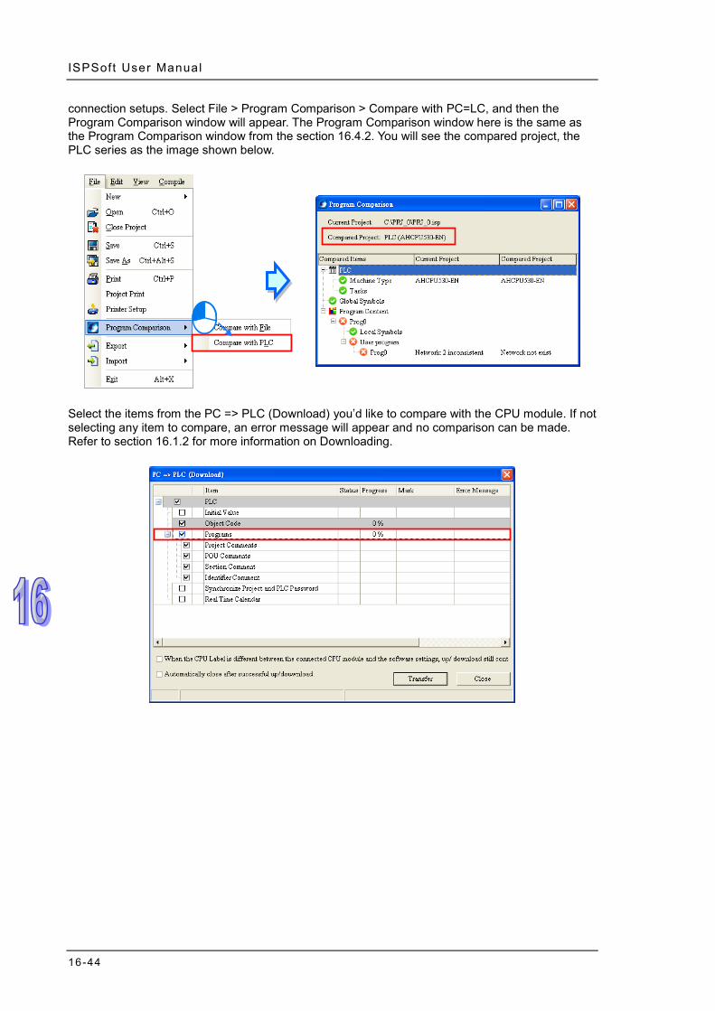
ISPSoft User Manual
16-44
connection setups. Select File > Program Comparison > Compare with PC=LC, and then the Program Comparison window will appear. The Program Comparison window here is the same as the Program Comparison window from the section 16.4.2. You will see the compared project, the PLC series as the image shown below.
Select the items from the PC => PLC (Download) you’d like to compare with the CPU module. If not selecting any item to compare, an error message will appear and no comparison can be made. Refer to section 16.1.2 for more information on Downloading.

Chapter 17 Test Tools and Debugging Tools
Table of Contents 17.1 Online Monitoring Function ..................................................................17-2
17.1.1 Changing the Operating Status of a PLC ......................................17-2 17.1.2 Online Monitoring Function and Environment ...............................17-2 17.1.3 Changing the States of the X Devices in the Online Mode ...........17-6 17.1.4 Monitoring a Program Online ........................................................17-7 17.1.5 Device Monitoring Table .............................................................17-13 17.1.6 Online Editing Function and Online Update Function .................17-18
17.2 DVP Series Simulator ........................................................................17-19 17.2.1 Creating a DVP Simulator ...........................................................17-19 17.2.2 Starting the DVP Simulator .........................................................17-20
17.3 Debugging Mode for a DVP Series PLC ............................................17-21 17.3.1 Enabling the Debugging Mode for a DVP Series PLC ................17-21 17.3.2 Adding and Clearing Breakpoints ...............................................17-22 17.3.3 Execution of the Program in the Debugging Mode .....................17-22
17.4 AH500 Series Simulator .....................................................................17-24 17.4.1 Creating and Starting an AH Simulator .......................................17-24 17.4.2 Operation Panel of an AH Simulator ...........................................17-25
17.5 Debugging Mode for an AH/AS Series CPU Module .........................17-31 17.5.1 Enabling the Debugging Mode for an AH500 Series CPU Module …………………………………………………………………………17-31 17.5.2 Adding and Clearing Breakpoints ...............................................17-31 17.5.3 Continuous Execution .................................................................17-32 17.5.4 Single-step Execution .................................................................17-32
17.6 Checking the Status of a PLC ............................................................17-34 17.6.1 System Information .....................................................................17-34 17.6.2 System Log (Only for AH/AS Series CPU Modules) ...................17-34
17.7 3D Chart ............................................................................................17-37 17.7.1 Features .....................................................................................17-37 17.7.2 Creating a 3D Chart ....................................................................17-37 17.7.3 Creating a Curve .........................................................................17-38 17.7.4 Display a 3D Chart ......................................................................17-40
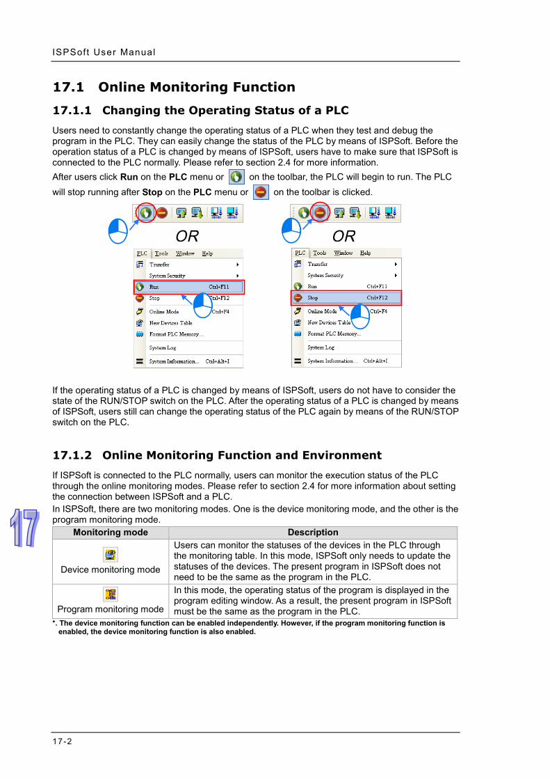
ISPSoft User Manual
17-2
17.1 Online Monitoring Function
17.1.1 Changing the Operating Status of a PLC
Users need to constantly change the operating status of a PLC when they test and debug the program in the PLC. They can easily change the status of the PLC by means of ISPSoft. Before the operation status of a PLC is changed by means of ISPSoft, users have to make sure that ISPSoft is connected to the PLC normally. Please refer to section 2.4 for more information. After users click Run on the PLC menu or on the toolbar, the PLC will begin to run. The PLC will stop running after Stop on the PLC menu or on the toolbar is clicked.
If the operating status of a PLC is changed by means of ISPSoft, users do not have to consider the state of the RUN/STOP switch on the PLC. After the operating status of a PLC is changed by means of ISPSoft, users still can change the operating status of the PLC again by means of the RUN/STOP switch on the PLC.
17.1.2 Online Monitoring Function and Environment
If ISPSoft is connected to the PLC normally, users can monitor the execution status of the PLC through the online monitoring modes. Please refer to section 2.4 for more information about setting the connection between ISPSoft and a PLC. In ISPSoft, there are two monitoring modes. One is the device monitoring mode, and the other is the program monitoring mode.
Monitoring mode Description
Device monitoring mode
Users can monitor the statuses of the devices in the PLC through the monitoring table. In this mode, ISPSoft only needs to update the statuses of the devices. The present program in ISPSoft does not need to be the same as the program in the PLC.
Program monitoring mode
In this mode, the operating status of the program is displayed in the program editing window. As a result, the present program in ISPSoft must be the same as the program in the PLC.
*. The device monitoring function can be enabled independently. However, if the program monitoring function is enabled, the device monitoring function is also enabled.

Chapter 17 Test Tools and Debugging Tools
17-3
After users click Online Mode on the PLC menu, or on the toolbar, the online monitoring function will be enabled. The system will also enable the device monitoring mode and the program monitoring mode.
If the users only want to monitor the statuses of the devices in the PLC, they can click on the toolbar. When on the toolbar is clicked, on the toolbar is also clicked. If the users want to monitor the program, they can click on the toolbar.
If the users want to disable the online monitoring function, they can click Online Mode on the PLC menu, or on the toolbar.

ISPSoft User Manual
17-4
In the online monitoring mode, users can view the present scan time and the status of the PLC in the status bar in ISPSoft. The light at the left side of the status of the PLC indicates the communication status. When ISPSoft communicates with the PLC, the light blinks.
If an error occurs in the PLC, users may not be able to operate the PLC, e.g. the PLC can not run. Please refer to the manual for the model used for more information about troubleshooting.
The present statuses of the devices will be displayed in the program editing window after the program monitoring function is enabled. Users can debug and test the program in the program monitoring mode. The way in which the statuses of the devices in a program are displayed depends on the programming language used to create the program. A ladder diagram in the program monitoring mode is shown below.
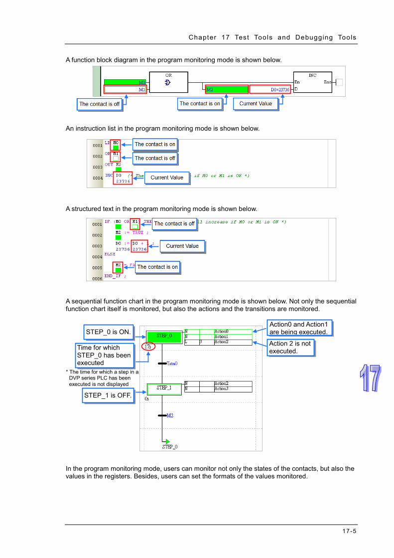
Chapter 17 Test Tools and Debugging Tools
17-5
A function block diagram in the program monitoring mode is shown below.
An instruction list in the program monitoring mode is shown below.
A structured text in the program monitoring mode is shown below.
A sequential function chart in the program monitoring mode is shown below. Not only the sequential function chart itself is monitored, but also the actions and the transitions are monitored.
In the program monitoring mode, users can monitor not only the states of the contacts, but also the values in the registers. Besides, users can set the formats of the values monitored.
* The time for which a step in a DVP series PLC has been executed is not displayed
Time for which STEP_0 has been executed
Action0 and Action1 are being executed.
Action 2 is not executed.
STEP_1 is OFF.
STEP_0 is ON.

ISPSoft User Manual
17-6
Click Monitoring Data Format on the View menu, and then select a data format on the drop-down list. If Automatically is selected, the formats of the values monitored depend on the data types of the symbols declared.
After users click Floating Format Setting on the View menu, they can set the formats of the floating-point numbers.
17.1.3 Changing the States of the X Devices in the Online Mode
In the online mode, users can change the states of the contacts in the program editing window. Users may not be allowed to change the states of the X devices in some PLCs in the online modes

Chapter 17 Test Tools and Debugging Tools
17-7
owing to the design of these PLCs. If users want to change the state of an X device, an error message will appear. Please refer to the manual for the model selected for more information.
If an X device needs to be operated when the program is tested, users can click on the toolbar to enable the function of setting the X device. However, the state of the X device will not be updated after the function is enabled.
After the online monitoring function is disabled, the function of setting the X device will not be disabled automatically. As a result, be sure to disable the function of setting the X device before the online monitoring function is disabled lest the state of the X device should not be updated during the operation of the PLC.
Before the state of a contact is changed, users have to make sure that the operation performed does not affect the operation of the system, or cause damage to the system or the staff,
17.1.4 Monitoring a Program Online
In the program monitoring mode, users can change the state of a contact or the value in a register in the program editing window. By means of changing the state of a contact or the value in a register, users can debug or test the program. If users want to manipulate a device or an operand in a ladder diagram or a function block diagram, they can click the device or the operand, right-click the device

ISPSoft User Manual
17-8
or the operand, and select an item on the context menu. The items on the context menu vary with the programming language used.
If users want to manipulate an operand on an instruction list or in a structured text, they can right-click the operand, and select an item on the context menu.
If users want to manipulate a step or a transition in a sequential function chart, they can right-click the step or the transition, and select an item on the context menu.

Chapter 17 Test Tools and Debugging Tools
17-9
If users want to manipulate a step or a transition in a continuous function chart, they can double click the shown status to switch from True to False or vice versa.
The items on the context menu are described below.
Item Description Set On Setting the contact selected to ON Set Off Setting the contact selected to OFF
Rising-edge Trigger No matter what the state of the contact selected is, the system set the contact to OFF, and then set it to ON.
Falling-edge Trigger No matter what the state of the contact selected is, the system set the contact to ON, and then set it to OFF.
Change Present Value Users can set the value of the operand selected. Force Forcing an input contact or output contact ON or OFF
Force Device List Forcing several input contacts or output contacts in the tables ON or OFF
Before the status of a device is changed, users have to make sure that the operation does not affect the operation of the system, or cause damage to the system or the staff.
Change Present Value
First, select an operand, and right-click the operand. Next, select Change Present Value on the context menu. Finally, set the value of the operand in the Enter Present Value window.

ISPSoft User Manual
17-10
Message
Users can type a value in the Present Value box.
Name of a device or a symbol whose present value will be changed
Users can type a 16-bit value or a 32-bit value.
Value change history (Format: Device name Value)
In the binary mode, users can set the states of the bits through the mouse.
The setting values will be applied after OK is clicked. The window will be closed after Cancel is clicked.
Users can display or hide the binary mode. In the continuous function charts, double click the value that you’d like to change, the field will become editable. Type the value in and click on the blank area or press Enter on the keyboard to complete the editing.
Press Enter

Chapter 17 Test Tools and Debugging Tools
17-11
Force
Only X contact and Y contacts and be forced ON or OFF. If an X contact is forced ON or OFF, the state of the contact will not be affected by the actual input. Likewise, if a Y contact is forced ON or OFF, the state of the contact will be affected by the program execution result. Y0.0 in the figure below is forced ON. It will be ON even if M0 is OFF. Besides, if a contact is forced ON or OFF, a lock symbol will appear at the left side of the contact.
Click an X contact or a Y contact which will be manipulated, right-click the X contact or the Y contact, point to Force on the context menu, and select On (X/Y), Off (X/Y), Release (X/Y), or Release All.
On (X/Y): Forcing the X contact or the Y contact selected ON
Off (X/Y): Forcing the X contact or the Y contact selected OFF
Release (X/Y): Releasing the contact from the locked state
Release All: Releasing all the contacts from the locked states
*1. The mechanism for forcing contacts ON/OFF, and the limit on the number of contacts which can be forced
ON/OFF vary from model to model. Please refer to the manual for the model selected for more information. *2. If the online monitoring function is disabled, the contacts will not be automatically released from the locked
states. Please check whether the present state will cause any problem.

ISPSoft User Manual
17-12
Force Device List Right-click the program editing window, and then select Force Device List on the context menu. Click the Device X tab or the Device Y tab in the Forced Devices List window. Select a contact in the table, right click the contact, and select an item on the context menu.
Force On (X/Y): Setting the contact selected to ON
Force Off (X/Y): Setting the contact selected to OFF
Release (X/Y): Releasing the contact from the locked state
Release All: Releasing all the contacts from the locked states
*1. The mechanism for forcing contacts ON/OFF, and the limit on the number of contacts which can be forced
ON/OFF vary from model to model. Please refer to the manual for the model selected for more information. *2. If the online monitoring function is disabled, the contacts will not be automatically released from the locked
states. Please check whether the present state will cause any problem.

Chapter 17 Test Tools and Debugging Tools
17-13
17.1.5 Device Monitoring Table
After users create monitoring tables, they can monitor the devices or the symbols in the tables online. Users are allowed to create more than one device monitoring table in a project in ISPSoft. 100 items at most can be added to a device monitoring table. Users can classify and manage the items which are monitored by themselves. Besides, device monitoring tables can be created online or offline. The device monitoring tables which are created in a project will be saved with the project, and users There are three ways to create a device monitoring table. Method 1
Click New Devices Table on the PLC menu.
Method 2
Right-click Device Monitoring Table in the project management area and click Add.
Method 3
Click on the toolbar.
Type a table name in the Add Monitor Table window, and then click OK. An item will be under Device Monitor Table in the project management area, and a device monitoring window will appear in the working area. Users can manage the items in the window.
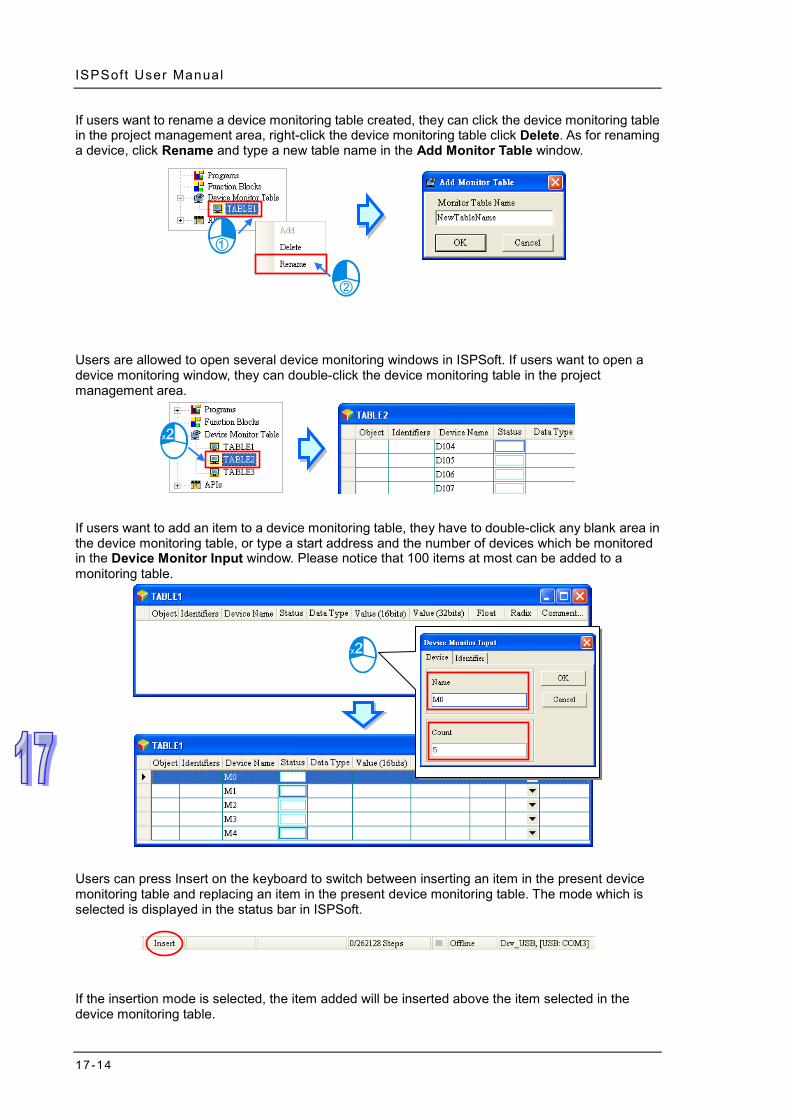
ISPSoft User Manual
17-14
If users want to rename a device monitoring table created, they can click the device monitoring table in the project management area, right-click the device monitoring table click Delete. As for renaming a device, click Rename and type a new table name in the Add Monitor Table window.
Users are allowed to open several device monitoring windows in ISPSoft. If users want to open a device monitoring window, they can double-click the device monitoring table in the project management area.
If users want to add an item to a device monitoring table, they have to double-click any blank area in the device monitoring table, or type a start address and the number of devices which be monitored in the Device Monitor Input window. Please notice that 100 items at most can be added to a monitoring table.
Users can press Insert on the keyboard to switch between inserting an item in the present device monitoring table and replacing an item in the present device monitoring table. The mode which is selected is displayed in the status bar in ISPSoft.
If the insertion mode is selected, the item added will be inserted above the item selected in the device monitoring table.

Chapter 17 Test Tools and Debugging Tools
17-15
If the replacement mode is selected, the item added will overwrite the item selected in the device monitoring table.
Users can click the Identifier tab and add identifiers in this Device Monitor Input window.
Users can add symbols as well as devices to a device monitoring table. After they right-click a device monitoring table, and select Select Symbols on the context menu, they can add symbols to the device monitoring table.
The users can select global symbols or local symbols in the POUs in the Symbols Select window. Before they select local symbols in a function block, the program must be compiled. After the function block instances declared in the superior POU are produced, they will be assigned substantial memory blocks. The users can monitor the local symbols in the function block instances. Different function block instances are assigned different memory blocks. If users want to monitor local symbols in a function block, they must select the local symbols in the instances of the function block. After the users select an item in the Object Source section, they can select symbols in the Symbols section. If a symbol whose data type is ARRAY is declared, the elements will be listed in

ISPSoft User Manual
17-16
the Symbols section. After symbols in the Symbols section are selected, the user can click Apply to add the symbols to the device monitoring table. The users can continue to select other symbols. After the users finish adding symbols to the device monitoring table, they can click Cancel to close the window.
*. The symbols whose data types are POINTER, the symbols whose data types are T_POINTER, the symbols whose data types are C_POINTER, and the symbols whose data types are HC_POINTER can not be monitored.
If the users want to delete an item in a device monitoring table, they can select the item, right-click the item, and click Delete on the context menu. If the users want to delete several items in a device monitoring table, they can select the items while they press Ctrl on the keyboard, right-click an item selected, and click Delete on the context menu. If the users want to delete a range of items in a device monitoring table, they can select the first item and the last item while they press Shift on the keyboard, right-click an item selected, and click Delete on the context menu. If the users want to delete all the items in a device monitoring table, they can right-click the device monitoring table, select Select All on the context menu, right-click an item selected, and select Delete on the context menu. The users can also delete the item selected or the items selected by pressing Delete on the keyboard.

Chapter 17 Test Tools and Debugging Tools
17-17
The users can hide some columns in a device monitoring table. If the users want to hide some columns in a device monitoring table, thy can right-click the device monitoring table, point to Set the Fields, and unselect items which correspond to the columns they want to hide. Please refer to the description of the columns below for more information.
The description of the columns in a device monitoring table is as follows.
Column Description Object The sources of the symbols are displayed. Identifier The identifiers of the symbols are displayed. Device Name The names of the devices monitored are displayed.
Status If the objects monitored are bit devices or contacts, the states of the bit devices or the states of the contacts will be displayed in this column.
Data Type If the objects monitored are symbols, the data types of the symbols will be displayed in this column.
Value (16 bits) When the devices and the symbols are monitored, the 16-bit values are displayed in this column.
Value (32 bits) When the devices and the symbols are monitored, the 32-bit values are displayed in this column.
Float When the devices and the symbols are monitored, the 32-bit floating-point numbers are displayed in this column.
Radix Users can select the formats of the values monitored.
Comment… The comments on the devices monitored, and the comments on the symbols monitored are displayed in this column.
After a device monitoring table is created, the users can monitor the items in the device monitoring table online. After the users right-click an item in a device monitoring table in the online mode, they can select an item on the context menu to change the state of the item monitored, or the value of the item monitored. Please refer to section 17.1.4 for more information.

ISPSoft User Manual
17-18
Additional remark If the comment on a device which is monitored is changed, users have to close the device monitoring table in which the device is added, and open the window again to get the new comment on the device. If the properties of a symbol in a device monitoring table are changed, or a symbol in a device monitoring table is removed from the symbol table, the symbol in the device monitoring table will not be updated, and will not have any effect in the online mode. Please delete the symbol from the device monitoring table, and add it again.
17.1.6 Online Editing Function and Online Update Function
When the system is in the online mode and the PLC is running, users can modify the program monitored through the online editing function and the online update function. Please refer to the following table for more information about the limits set on the editing of programs. Programming
language Description
Ladder diagram
One network is edited at a time. Users are allowed to add new networks. After a new network is added, the network which can be edited will be the new network, that is, the previous networks can not be edited.
Function block diagram
One network is edited at a time. Users are allowed to add new networks. After a new network is added, the network which can be edited will be the new network, that is, the previous networks can not be edited.
Instruction list There is no limit on the number of lines which can be edited. Structured text There is no limit on the number of lines which can be edited.
Sequential function chart
A sequential function chart can not be modified online, but actions and transitions can be modified. The limit set on the editing of an action or a transition depends on the language used to create the action or the transition.
Continuous function chart No limit on the editing.
Common limit After the program is edited, users can only edit one POU. In the online editing mode, users can not modify or add a symbol.
If users want to edit the program online, they must enable the program monitoring function, make sure that the PLC runs, and click on the toolbar.

Chapter 17 Test Tools and Debugging Tools
17-19
If the online editing function is enabled, On-line Edit will be displayed in the status bar in ISPSoft.
If the editing of the program is complete and the program is compiled successfully, the program will be downloaded to the PLC after users click on the toolbar. If the program is not compiled, the system will ask users to compile the program.
17.2 DVP Series Simulator
17.2.1 Creating a DVP Simulator
Start COMMGR, and then click Add in the COMMGR window to create a driver. Please refer to section 2.4 for more information about COMMGR.
Type a driver name in the Driver Name box, select DVP Simulator in the Type drop-down list box, select the number of times the sending of a command is retried in the Time of Auto-retry box, and select an interval of retrying the sending of a command in the Time Interval of Auto-retry box. After the setting is complete, users can click OK to create a DVP simulator.

ISPSoft User Manual
17-20
(1) Type a driver name in the Driver Name box. (2) Select DVP Simulator in the Type drop-down list box in the Connection Setup section. (3) Users can select the number of times the sending of a command is retried if a connection error
occurs in the Time of Auto-retry box, and select an interval of retrying the sending of a command in the Time Interval of Auto-retry box.
*. Users can only create a DVP simulator in COMMGR. If users want to create the second DVP simulator, a warning message will appear.
17.2.2 Starting the DVP Simulator
Open the COMMGR window, and then start the DVP simulator in COMMGR.
Click Communication Settings… on the Tools menu in ISPSoft, select the DVP simulator in the Driver box in the Communication Setting window, and click OK.
After the communication setting is complete, the connection type displayed in the status bar in ISPSoft will be a DVP simulator.
COMMGR will transmit data between ISPSoft and the DVP simulator once related connection operation is performed. During the connection, users can only download the program in ISPSoft to the DVP simulator, upload the program in the DVP simulator to ISPSoft, enable the online monitoring function, edit devices, and registers, and force X devices ON/OFF.
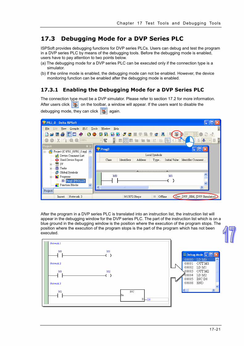
Chapter 17 Test Tools and Debugging Tools
17-21
17.3 Debugging Mode for a DVP Series PLC ISPSoft provides debugging functions for DVP series PLCs. Users can debug and test the program in a DVP series PLC by means of the debugging tools. Before the debugging mode is enabled, users have to pay attention to two points below. (a) The debugging mode for a DVP series PLC can be executed only if the connection type is a
simulator. (b) If the online mode is enabled, the debugging mode can not be enabled. However, the device
monitoring function can be enabled after the debugging mode is enabled. 17.3.1 Enabling the Debugging Mode for a DVP Series PLC
The connection type must be a DVP simulator. Please refer to section 17.2 for more information. After users click on the toolbar, a window will appear. If the users want to disable the debugging mode, they can click again.
After the program in a DVP series PLC is translated into an instruction list, the instruction list will appear in the debugging window for the DVP series PLC. The part of the instruction list which is on a blue ground in the debugging window is the position where the execution of the program stops. The position where the execution of the program stops is the part of the program which has not been executed.

ISPSoft User Manual
17-22
17.3.2 Adding and Clearing Breakpoints
After users right-click a line in the debugging window and select Set Break Point on the context menu, a breakpoint will be added to the line. If the users right-click the line again and select Set Break Point on the context menu, the breakpoint will be canceled. In the debugging window, an exclamation appears at the beginning of the line to which a breakpoint is added, and the line is on a red ground.
If users want to clear the breakpoints in the debugging window, they can right-click a line, and select Clear All Break Points on the context menu.
17.3.3 Execution of the Program in the Debugging Mode
Continuous execution After on the toolbar is clicked, the execution of the program will stop at a breakpoint. If users click again, the execution of the program will continue, and will stop at the next breakpoint. If there are no breakpoints, the program will be scanned repeatedly after clicked.

Chapter 17 Test Tools and Debugging Tools
17-23
Single-step execution If the execution of the program stops, single-step execution will be performed after on the toolbar is clicked.
Setting the number of times the program is executed
If the number of times the program is scanned reaches the number specified, the scan will stop. Besides, the scan of the program is not affected by the breakpoints in the program. Users have to set a number in on the toolbar. The maximum number which can be set is 32767. Click on the toolbar after the setting is complete.
Stopping the execution of the program and resetting the execution order
After users click on the toolbar, the execution of the program stops.
After on the toolbar is clicked, the execution order and the values will be reset. The execution of the program will start form the beginning of the program next time the program is executed.
*. After the debugging mode for a DVP series PLC is enabled, the devices in the device monitoring table still can be
monitored.

ISPSoft User Manual
17-24
17.4 AH500 Series Simulator
17.4.1 Creating and Starting an AH Simulator
Start COMMGR, and then click Add in the COMMGR window to create a driver. Please refer to section 2.4 for more information about COMMGR.
Type a driver name in the Driver Name box, select AH Simulator in the Type drop-down list box, type a communication port number in the Port Number box, select the number of times the sending of a command is retried in the Time of Auto-retry box, and select an interval of retrying the sending of a command in the Time Interval of Auto-retry box. After the setting is complete, users can click OK to create an AH simulator.
(1) Type a driver name in the Driver Name box. (2) Select AH Simulator in the Type drop-down list box in the Connection Setup section. (3) Users can type a communication port number in the Port Number box. If it is not necessary to
specify a communication port number, please use the default communication port number. Besides, if several AH simulators are created, the communication port numbers assigned to the AH simulators can not be the same, and the system skips the port numbers which have been specified.
(4) Users can select the number of times the sending of a command is retried if a connection error occurs in the Time of Auto-retry box, and select an interval of retrying the sending of a command in the Time Interval of Auto-retry box.
Open the COMMGR window, and then start an AH simulator in COMMGR. After the AH simulator is

Chapter 17 Test Tools and Debugging Tools
17-25
started, a window will appear. The title of the window is the driver name of the AH simulator. Besides, users are allowed to create several AH simulators, but eight AH simulators at most can be started simultaneously.
Click Communication Settings… on the Tools menu in ISPSoft, select the AH simulator in the Driver box in the Communication Setting window, and click OK. After the communication setting is complete, the connection type displayed in the status bar in ISPSoft will be an AH simulator.
COMMGR will transmit data between ISPSoft and the AH simulator once related connection operation is performed. The software functions, parameters, and instructions which are not supported by an AH simulator are as follows.
Software function
NWCONFIG, CARD Utility, the I/O scan provided by HWCONFIG, and the online mode provided by HWCONFI
Parameter Module parameters, communication port parameters, Ethernet parameters, and parameters related to a memory card
Instruction
RS, FWD, REV, STOP, RDST, RSTEF, MODRW, FROM, TO, READ, WRITE, RPASS, SRCVD, SSEND, SOPEN, SCLOSE, MSEND, EMDRW, MWRIT, MREAD, MTWRIT, and REF are not supported. Accessing X devices and Y devices directly is also not supported.
17.4.2 Operation Panel of an AH Simulator
Introduction of the operation panel of an AH simulator After an AH simulator in COMMGR is started, the operation panel of the AH simulator will appear. The lights and buttons on the operation panel correspond to the lights and buttons on an AH500 CPU module. Users can simulate the operation of an actual AH500 CPU module by means of the

ISPSoft User Manual
17-26
operation panel. Please refer to the manuals related to AH500 CPU modules for more information about the lights and the buttons on the operation panel.
After the operation panel is closed, the status of the AH simulator displayed in COMMGR will be STOP. Likewise, if the status of the AH simulator displayed in COMMGR becomes STOP, the operation panel will be closed. After the operation panel is closed, the program and the parameters which have been downloaded will be reserved, and will be loaded into the AH simulator next time the AH simulator is started. Besides, if the computer is restarted, the system will start COMMGR automatically, and the statuses of the AH simulators displayed in COMMGR will become STOP.
A hardware configuration can be simulated in the AH simulator. As a result, after the parameters in HWCONFIG is downloaded to the AH simulator, the parameters will be memorized in the AH simulator. If the modules which are configured include a digital I/O module, an analog I/O module, and a temperature measurement module, an operation panel for these modules will appear after users click IO Module on the operation panel of the AH simulator. The users can simulate input statuses and output statuses through the panel. However, if the users want to simulate input statuses and output statuses, the AH simulator must run.
The AH simulator simulates the functions of an AH500 series CPU module. Although the parameters in the I/O modules can be downloaded to the AH simulator, the processing procedures in the actual I/O modules can not be simulated. The users can only debug or test the program by means of the states of the X devices, the states of the Y devices, and the values in the D registers in the modules.
Introduction of the operation panel for I/O modules The operation panel for AH16AP11R-5A, AH06XA-5A, and AH04PT-5A are shown below. The names of the I/O modules, the rack that the modules occupy, the slot that the modules occupy, the input devices, and the output devices are displayed on the operation panel.

Chapter 17 Test Tools and Debugging Tools
17-27
The input devices and the output devices in the red frame in HWCONFIG below are the same as the devices in the red frame in the Input & Output Module Information window above. As a result, users can simulate input statuses and output statuses by means of the operation panel.
The input devices and the output devices assigned to AH16AP11R-5A are shown below. Users can view the states of the Y devices, but they can not manipulate the Y devices. Besides, users can manipulate the states of the X devices by clicking the X devices.
The input devices and the output devices assigned to AH06XA-5A are shown below. The values in the boxes are 32-bit floating-point numbers. Users can view the values in the boxes above D8 and D10, but they can not set values in the boxes. Besides, users can simulate input signals by setting values in the boxes above D0, D2, D4, and D6. The values in the boxes are the values in the D devices, and are not analog values.

ISPSoft User Manual
17-28
Setting simulated analog input signals
If users want to set an analog input value in the box above a device, they have to click at the right side of the box to open the Analog Input Value window.
The Analog Input Value window is shown below. Select a signal type, and then type values at the right side of the signal type selected. Please refer to the following table for more information about the signal types in the Analog Input Value window.
Signal type Description Constant Users can specify a constant. Random Users can specify a maximum value and a minimum value.
Sine Wave Users can specify a maximum value, a minimum value, and specify a cycle.
Square Wave Users can specify a maximum value, a minimum value, a high period, and a low period.
Triangle Wave Users can specify a maximum value, a minimum value, and a cycle.
After the setting is complete, the signals sent to COMMGR will depend on the signal types selected. ISPSoft can get the input signals received by the AH simulator by means of COMMGR.

Chapter 17 Test Tools and Debugging Tools
17-29
Hiding the modules displayed on the operation panel for I/O modules Right-click the operation panel for the I/O modules, and then click IO Module Visible Settings on the context menu. If users select a module in the IO Module Visible Setting window, the module will be displayed. If users unselect a module in the IO Module Visible Setting window, the module will be hid. If users select or unselect the Select All checkbox in the IO Module Visible Setting window, all the modules in the IO Module Visible Setting window will be selected or unselected. Finally, click OK.
The numbers in the lower right corner indicates the number of modules which are displayed and the total number of modules. The format is Number of modules which are displayed/Total number of modules. If users want to display all the modules, they can right-click the operation panel, and select Show All IO Modules on the context menu.

ISPSoft User Manual
17-30
Backing up the data in an AH simulator and restoring the data to the AH simulator The parameters and the program downloaded to the AH simulator can be backed up onto the computer. The backup file can be restored to the AH simulator, or copied into other AH simulators. If users want to backing up the data in the AH simulator, they have to right-click the operation panel of the AH simulator, click Backup on the context menu, specify a path in the Save As window, type a file name in the File name box, and click Save.
If the users want to restore the data, they have to right-click the operation panel of the AH simulator, click Restore on the context menu, click the backup file in the Open window, and click Open.

Chapter 17 Test Tools and Debugging Tools
17-31
17.5 Debugging Mode for an AH/AS Series CPU Module
17.5.1 Enabling the Debugging Mode for an AH500 Series CPU Module
The debugging mode which ISPSoft provides for AH/AS series CPU modules supports all the programming languages. However, the debugging functions can only be executed in the actions in a sequential function chart, and the steps to which the actions belong must be ON. Besides, if the state of a transition in a sequential function chart does not make the transition from one step to another step, users must change the state of the transition. Click on the toolbar, click on the toolbar, and click on the toolbar.
If the debugging mode is not enabled, but the CPU module is in the debugging mode, the debugging mode can not be enabled. (When the CPU module is in the debugging mode, Debug is displayed in the status bar in ISPSoft.) The reason is that the debugging mode was not disabled normally last time or another user on the network is debugging the program in the CPU module. If users want to reset the debugging mode, they must stop the CPU module, start the CPU module again, and enable the debugging mode.
17.5.2 Adding and Clearing Breakpoints
Ten breakpoints at most can be added to the program in a project for an AH500 series CPU module. After users click a position in a program editing window and click on the toolbar, a breakpoint will be added to the position. If the users click the position again and click on the toolbar, the breakpoint will be canceled.
If users want to clear all the breakpoints in the program in an AH500 series CPU module, they can click on the toolbar.
After on the toolbar is clicked, the execution of the program will stop at a breakpoint. If users click again, the execution of the program will continue, and will stop at the next breakpoint. The position where the execution of the program stops is the part of the program which has not

ISPSoft User Manual
17-32
been executed.
17.5.3 Continuous Execution
If on the toolbar is clicked, the execution of the program will stop at a breakpoint. If users click again, the execution of the program will continue, and will stop at the next breakpoint. If there
are no breakpoints, the program will be scanned repeatedly after is clicked.
17.5.4 Single-step Execution
After or on the toolbar is clicked, the part of the program selected will be executed. If a function block is selected, the function block will be executed after is clicked, and the first step in the function block will be executed after is clicked. However, if the function block selected is

Chapter 17 Test Tools and Debugging Tools
17-33
protected with a password, or the state of the En pin of the function block selected is OFF, the first step in the function block will not be executed whether or is clicked. Besides, if users want to perform single-step execution in a structured text, they must add breakpoints to the structured text. If users want to perform single-step execution in the POUs following a sequential function chart, they must add breakpoints to the POUs. The different between and is shown below.

ISPSoft User Manual
17-34
17.6 Checking the Status of a PLC
17.6.1 System Information
If ISPSoft is connected to the PLC normally, the system will retrieve information from the PLC after users click System Information… on the PLC menu.
17.6.2 System Log (Only for AH/AS Series CPU Modules)
The actions and the errors which occur in an AH500 series CPU module are stored in special data registers in the AH/AS series CPU module. If ISPSoft is connected to an AH500 series CPU module normally, users can view the actions and the errors which occur in the AH500 series CPU module after they click System Log on the PLC menu. After users click System Log on the PLC menu, the System Log window will appear. There are several tabs in the System Log window. The data displayed in the window is the data retrieved from the CPU module. The data displayed in the window is not synchronized with the data in the CPU module. After users click Refresh in the window, the data displayed in the window will be updated.
Error Log
After users click the Error Log tab, they can view the errors occurring in the CPU module and the I/O modules. The error codes which correspond to the errors occurring in the CPU module and the I/O modules, the points when errors occur in the CPU module and the I/O modules, the descriptions of the errors occurring in CPU module and the I/O modules, the modules where errors occur, the racks which are occupied by the modules where errors occur, and the slots which are occupied by the modules where errors occur are displayed in the window.

Chapter 17 Test Tools and Debugging Tools
17-35
After users click Refresh, the system will retrieve data from the CPU module, and the data displayed in the window will be updated. After users click Clear Log, the error log in the window and the error log in the CPU module will be cleared, and the CPU module will be reset. If the reasons for the errors still exist, the errors will still occur in the CPU module, and the new error log related to the errors will be produced.
Error logs can be stored in the SD card and then the logs can be moved to the PC for better
management. Refer to character 3 for more information on how to save error logs to the SD card.
After that users can go to Tools > Review Error Log File and press Open Log File to select the path
where the error log saved to see the contents of the error log.
Program Change Log
After users click the Program Change Log tab, they can view the log related to the downloading/uploading of programs and the downloading/uploading of parameters. After users click Refresh, the system will retrieve data from the CPU module, and the data displayed in the window will be updated. After users click Clear Log, the program change log in the window and the program change log in the CPU module will be cleared.

ISPSoft User Manual
17-36
Status Change Log
After users click the Status Change Log tab, they can view the log related to the change of the status of the CPU module. After users click Refresh, the system will retrieve data from the CPU module, and the data displayed in the window will be updated. After users click Clear Log, the status change log in the window and the status change log in the CPU module will be cleared.
Axis Log After users click the Axis Log tab, they can view the log related to the axis. After users click Refresh, the system will retrieve data from the CPU module, and the data displayed in the window will be updated. After users click Clear Log, the axis log in the window and the axis log in the CPU module will be cleared.

Chapter 17 Test Tools and Debugging Tools
17-37
*.Axis log is only available for AHxxEMC.
17.7 3D Chart
17.7.1 Features
During the operation of the multi-axis interpolation in the monitoring mode, users can use the 3D chart to see the motion traces, variables and devices, providing a way to check the accuracy of the motion and a way to analyze the value trend.
*. This function is only available for AHxxEMC.
17.7.2 Creating a 3D Chart Right-click the 3D Chart in the project management area and then click Add to bring out a New Trace Item window, type the trace name in the field to create a trace. One project can add up to 10 sets of 10 traces.
Once a trace is created, the 3D chart window will show up automatically. Users can also find it under

ISPSoft User Manual
17-38
the option 3D Chart and double click it to open its editing window.
Right-click the created trace, users can use the options to delete or click Property to rename the selected trace.
17.7.3 Creating a Curve
Click the button on the 3D chart editing page to bring out a Curve Setting page.

Chapter 17 Test Tools and Debugging Tools
17-39
Type a name for the new curve and define the sources and other related settings for the X-, Y-, Z- axes. Setting the source to Position or Speed for the axes means the data of the 3D chart is from the positon or speed of the axes. Users can use the drop-down list to select the created axes. When the PLC runs the motion control program, the positon or speed of the set axis can be monitored in real time.
Setting the source to Device for the axes means the data of the 3D chart is from the device of the axes. Users can use the drop-down list to select the created device address and select the type. When the PLC runs the program, the address and type of the device of the set axis can be monitored.
Setting the source to Variable for the axes means the data of the 3D chart is from the variable of the axes. Users can use the … to open a Symbol Select page and select the created variable from the Symbols section. The system will bring in the suitable type automatically.

ISPSoft User Manual
17-40
Setting the source to Time for the axes means the data of the 3D chart is from the time of the axes and the value of axes will be increased by 1 every second.
Set up the width and the color for the curve and then click OK on Curve Setting page to complete the creation of a curve. After that the created curve will be listed below the 3D chart. Click to select a curve you’d ike to edit. Click to delect the selected or click … to open the curve set up page and set up again. Use the drop-down list to change the color of the selected curve and select or deselect the checkbox to show or hide the curve on the 3D chart. Up to 10 curves can be added on one 3D chart.
17.7.4 Display a 3D Chart
Follow the procedures aforementioned to download program and complete the monitoring setups. After a 3D chart is created, make sure the motion control CPU is connected to your computer and then the 3D chart will be displayed.

Chapter 17 Test Tools and Debugging Tools
17-41
To edit a created curve, users can use the drop-down list on the area or click to select a curve from the list. After selection, click and to edit the curve or click to delete the selected curve.
Use options in the View Mode section to change the view of the chart; selections are 3D, XY Plane, ZX Plane and YZ Plane. Other view options include to show or not to show the Draw Points, Shadow, Draw Grids and Auto Fit. When Auto Fit is selected, the display area will auto adjust the X, Y, Z axes according to the traces to fit the screen.
3D chart display area. List of the curves created. Users can use click and drag the trace on the 3D chart to see the chart from different angles. Use the mouse wheel to scroll and adjust the scale of the chart.
Move the cursor pointer to the trace on the 3D chart and it will show its coordinates, as the image shown below.

ISPSoft User Manual
17-42
MEMO

Chapter 18 Password Management and Data Protection
Table of Contents 18.1 Password Protection Mechanisms Provided by ISPSoft ......................18-2 18.2 Program ID and PLC ID .......................................................................18-3
18.2.1 Setting and Unlocking a Program ID .............................................18-3 18.2.2 Setting and Unlocking a PLC ID ...................................................18-4
18.3 Project Password and PLC Password .................................................18-5 18.3.1 Setting and Unlocking a Project Password ...................................18-5 18.3.2 Setting and Unlocking a PLC Password .......................................18-6 18.3.3 Making a Project Password and a PLC Password Become the Same …………………………………………………………………………..18-8
18.4 POU Password and Settings Protection ..............................................18-8 18.5 Subroutine Password ...........................................................................18-9
18.5.1 Introduction of a Subroutine Passwords .......................................18-9 18.5.2 Setting and Unlocking a Subroutine Password ...........................18-10
18.6 Other Password Protection functions and Data Protection Functions 18-11 18.6.1 Inactivating the Uploading of the Program from a DVP Series PLC …………………………………………………………………………18-11 18.6.2 Setting Read-only Device Ranges in a DVP Series PLC ............18-12 18.6.3 Setting a TC-01 Password Key (for a DVP Series PLC) .............18-12

ISPSoft User Manual
18-2
18.1 Password Protection Mechanisms Provided by ISPSoft
To protect the programs or the core techniques developed by users, ISPSoft provides multiple protection mechanisms for the projects developed by the users. The password protection mechanisms provided by ISPSoft are shown below. Users can set or unlock the passwords, and adopt different data protection mechanisms according to their needs.
Password type Description
ISPSoft project
Program ID
This is the first authentication information which needs to be checked on. If users want to download a project to a PLC, the program ID set in the project must be the same as the PLC ID set in the PLC. A specific project can only be downloaded to a specific PLC.
Project password
The project password set in a project is used to protect the program in the project. If users want to open the POUs in a project protected by a project password, the system will require the users to type the correct password.
POU password
The POU password set in a POU is used to protect the POU. Users can set a password in a POU to protect the source code or the core technique in the POU.
Subroutine password
A subroutine password set in a subroutine is used to protect the subroutine. It prevents the programs in the function blocks from being analyzed after the programs are uploaded. This function only supports DVP series PLCs. AH/AS series CPU modules adopts another mechanism.
Settings Password
The tool password set in different programs in different series is used for the protection of settings such as G-code, E-CAM and Position Planning Table uploading.
PLC PLC ID This is the first authentication information which needs to be checked on. If users want to download a project to a PLC, the program ID set in the project must be the same as the PLC ID set in the PLC. A specific

Chapter 18 Password Management and Data Protect ion
18-3
Password type Description project can only be downloaded to a specific PLC.
PLC password
The PLC password set in a PLC is used to protect the data in the PLC. If users want to download the data protected by a PLC password to a PLC, or upload the data protected by a PLC password from a PLC, they have to type the correct password.
18.2 Program ID and PLC ID An ID is the first authentication information which needs to be checked on. If users want to download a project to a PLC, the program ID set in the project must be the same as the PLC ID set in the PLC. The project which is protected by a program ID can only be downloaded to a specific PLC, and the PLC ID set in the PLC must be the same as the program ID.A specific project can only be downloaded to a specific PLC. If users want to upload a project to a PLC protected by a PLC ID, the system will ask the users to type the correct ID before the project is uploaded. If users want to open a project protected by a program ID, the system will ask the users to type the correct ID before the project is opened. As a result, an ID is used for access approval to gain access to data.
18.2.1 Setting and Unlocking a Program ID
After users click the Tools menu, point to Program Settings, and click Program ID Setting, the Program ID Setting window will appear. The message at the bottom of the window indicates whether the project is protected by a program ID.
If the project is not protected by a program ID, there will be two boxes used to set a program ID in the Program ID Setting window. If the users want to set a program ID, they have to type the same password in the two boxes, and click OK. If the project is protected by a program ID, there will be one box used to unlock the program ID in the Program ID Setting window. If the users want to unlock the program ID, they can type the correct ID in the box, and click OK. If the users want to set a program ID, they can only type English letters, numerical digits, and spaces in the window. A program ID is case-sensitive. Besides, the limit on the number of characters which can be typed depends on the model selected. The users have to type a program ID according to the hint in the window. After the users set a program ID, the project will be protected by the program ID. The window will be closed after the users click Cancel.

ISPSoft User Manual
18-4
18.2.2 Setting and Unlocking a PLC ID
Before users set a PLC ID, they have to make sure that ISPSoft is connected to the PLC normally. Please refer to section 2.4 for more information. After users click the PLC menu, point to System Security, and click PLC ID Setting, ISPSoft will connect to the PLC, and read the information from the PLC. If the reading of the information from the PLC is successful, ISPSoft will open the PLC ID Setting window. The message at the bottom of the window indicates whether the PLC is protected by a program ID.
If the PLC is not protected by a PLC ID, there will be two boxes used to set a PLC ID in the PLC ID Setting window. If the users want to set a PLC ID, they have to type the same password in the two boxes, and click OK. If the PLC is protected by a PLC ID, there will be one box used to unlock the PLC ID in the PLC ID Setting window. If the users want to unlock the PLC ID, they can type the correct ID in the box, and click OK. If the users want to set a PLC ID, they can only type English letters, numerical digits, and spaces in the window. A PLC ID is case-sensitive. Besides, the limit on the number of characters which can be typed depends on the model selected. The users have to type a PLC ID according to the hint in the window. After the users set a PLC ID, the PLC will be protected by the PLC ID. The window will be closed after the users click Cancel.

Chapter 18 Password Management and Data Protect ion
18-5
18.3 Project Password and PLC Password The project password set in a project is used to protect the program in the project. If users want to open the POUs in a project protected by a project password, the system will require the users to type the correct password. Besides, the users can limit the total number of password guesses that can be made. If the number of password guesses that is made is larger than the total number of password guesses that can be made, the project will be closed automatically. The PLC password set in a PLC is used to protect the data in the PLC. If users want to download or upload a project, the system will ask the users to type the correct password. Besides, the users can limit the total number of password guesses that can be made. If the number of password guesses that is made is larger than the total number of password guesses that can be made, the PLC will be locked, and the data can not be downloaded/uploaded. To unlock the PLC, the users have to restore the PLC to the default setting.
18.3.1 Setting and Unlocking a Project Password
After users click the Tools menu, point to Program Settings, and click Project Password Setting, the Project Password Setting window will appear. The message at the bottom of the window indicates whether the project is protected by a project password. If the project opened is a project for a DVP series PLC, the Program Copy to PCC01 checkbox will appear in the Project Password Setting window.
If the project is not protected by a project password, there will be two boxes used to set a project password in the Project Password Setting window. If the users want to set a project password, they have to type the same password in the two boxes, and click OK. The users can only type English letters, numerical digits, and spaces in the window. A project password is case-sensitive. Besides, the limit on the number of characters which can be typed depends on the model selected. The users have to type a project password according to the hint in the window.

ISPSoft User Manual
18-6
If the users want to limit the total number of password guesses that can be made, they can select the Enable Limited Times checkbox, and select a number in the box at the right side of the checkbox. If users want to copy the program into DVPPCC01, they can select the Program Copy to PCC01 checkbox. (Please refer the additional remark below for more information.) After the users set a project password, the project will be protected by the project password. The window will be closed after the users click Cancel.
If the project is protected by a project password, there will be one box used to unlock the project password in the Project Password Setting window. If the users want to unlock the project password, they can type the correct password in the box, and click OK. After the project password is unlocked successfully, the project will not protected by the project password. The window will be closed after the users click Cancel.
Additional remark DVPPCC01 is a data backup memory card for DVP series PLCs. If the Program Copy to PCC01 checkbox in the Project Password Setting window is selected, the PLC connected to ISPSoft will be in a status after the project is downloaded to the PLC. If DVPPCC01 is inserted into the PLC when the PLC is in that status, the project downloaded to the PLC will be backed up onto DVPPCC01. However, if the PLC receives another communication command before DVPPCC01 is inserted, the program will not be copied into DVPPCC01. This function supports DVP-ES2 series PLCs. Please refer to the related user manuals or technical documents for more information about the firmware versions which support this function and the usage of DVPPCC01. 18.3.2 Setting and Unlocking a PLC Password
Before users set a PLC password, they have to make sure that ISPSoft is connected to the PLC normally. Please refer to section 2.4 for more information.

Chapter 18 Password Management and Data Protect ion
18-7
After users click the PLC menu, point to System Security, and click Password Setting, ISPSoft will connect to the PLC, and read the information from the PLC. If the reading of the information from the PLC is successful, ISPSoft will open the Password Setting window. The message at the bottom of the window indicates whether the data in the PLC is protected by a PLC password.
If the data in the PLC is not protected by a PLC password, there will be two boxes used to set a PLC password in the Password Setting window. If the users want to set a PLC password, they have to type the same password in the two boxes, and click OK. If the users want to limit the total number of password guesses that can be made, they can select the Enable Limited Times checkbox, select a number in the box at the right side of the checkbox, and click OK. If the data in the PLC is protected by a PLC password, there will be one box used to unlock the PLC password in the Password Setting window. If the users want to unlock the PLC password, they can type the correct password in the box, and click OK. The users can only type English letters, numerical digits, and spaces in the window. A PLC password is case-sensitive. Besides, the limit on the number of characters which can be typed depends on the model selected. The users have to type a project password according to the hint in the window. After the users set a PLC password, the data in the PLC will be protected by the PLC password. The window will be closed after the users click Cancel.

ISPSoft User Manual
18-8
18.3.3 Making a Project Password and a PLC Password Become the Same
ISPSoft provides a convenient function for users. During the downloading/uploading of a project, users can make the project password and the PLC password become the same. If users select the Synchronize Project and PLC Password checkbox in the Transfer Setup window, the PLC password will become the same as the project password after the project is downloaded. If the users do not set a project password, the system will ask the users to set a project password after the users select the Synchronize Project and PLC Password checkbox in the Transfer Setup window. Besides, if the users open an old project which is protected by a project password, the Synchronize Project and PLC Password checkbox in the Transfer Setup window will be selected.
18.4 POU Password and Settings Protection ISPSoft allows users to set a password in a POU. If users want to open a POU protected by a password, the system will ask the users to type the correct password. The password set in a POU protects the source code or the core technique in the POU. The setting of a POU password and the unlocking of a POU password are described below. Right-click a POU in the project management area and click Properties…. The Protection section in the Properties window indicates whether the POU is protected by a POU password.

Chapter 18 Password Management and Data Protect ion
18-9
If the POU is not protected by a POU password, there will be two boxes used to set a POU password in the Protection section. If the users want to set a POU password, they have to type the same password in the two boxes. The users can only type English letters, numerical digits, and marks in the window. A POU password is case-sensitive. After the setting of a POU password is complete, the users can click OK. If the POU is protected by a POU password, there will be one box used to unlock the POU password in the Protection section. If the users want to unlock the POU password, they can type the correct password in the box, and click OK.
* Users can set a POU password when they create a POU. Please refer to section 5.4.1 for more information. * ISPSoft provides password protections for different design tools, including G-code, E-CAM and Position Planning
Table uploading, refer to chapter 21 and 22 for more information.
18.5 Subroutine Password
18.5.1 Introduction of a Subroutine Passwords
After the program in a project for a DVP series PLC is compiled, the object code produced by the system may include a main program, a general subroutine, and an interrupt subroutine. The subroutine is transformed from the source code in the POUs of the function block type in the project. If the Program checkbox in the Transfer Setup window is not selected, and the Object Code checkbox in the Transfer Setup window is selected, the general subroutine which is a part of the object code will be transformed into POUs of the function blocks type in ISPSoft after the object code is uploaded. Owing to the fact that a POU password protects the source code in a POU, the POUs transformed from the object code are not protected by POU passwords. Users can open the POUs of the function block type at will, and analyze the contents of the POUs.
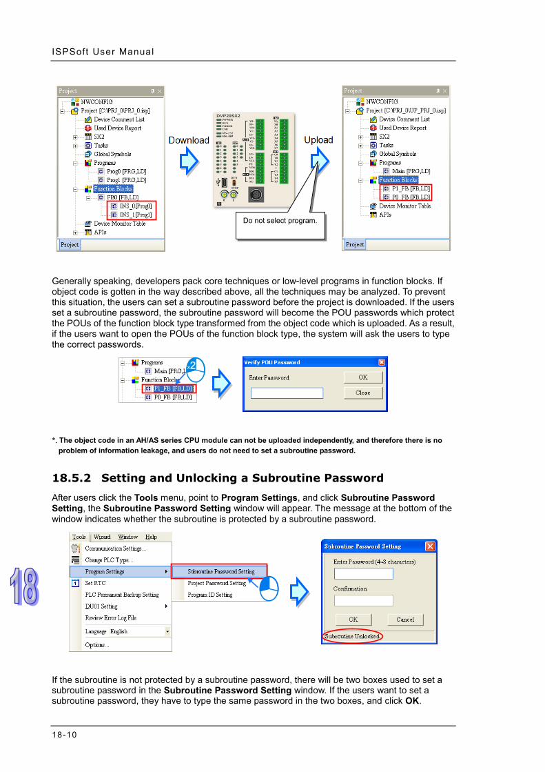
ISPSoft User Manual
18-10
Generally speaking, developers pack core techniques or low-level programs in function blocks. If object code is gotten in the way described above, all the techniques may be analyzed. To prevent this situation, the users can set a subroutine password before the project is downloaded. If the users set a subroutine password, the subroutine password will become the POU passwords which protect the POUs of the function block type transformed from the object code which is uploaded. As a result, if the users want to open the POUs of the function block type, the system will ask the users to type the correct passwords.
*. The object code in an AH/AS series CPU module can not be uploaded independently, and therefore there is no
problem of information leakage, and users do not need to set a subroutine password.
18.5.2 Setting and Unlocking a Subroutine Password After users click the Tools menu, point to Program Settings, and click Subroutine Password Setting, the Subroutine Password Setting window will appear. The message at the bottom of the window indicates whether the subroutine is protected by a subroutine password.
If the subroutine is not protected by a subroutine password, there will be two boxes used to set a subroutine password in the Subroutine Password Setting window. If the users want to set a subroutine password, they have to type the same password in the two boxes, and click OK.
Do not select program.

Chapter 18 Password Management and Data Protect ion
18-11
If the subroutine is protected by a subroutine password, there will be one box used to unlock the subroutine password in the Subroutine Password Setting window. If the users want to unlock the subroutine password, they can type the correct password in the box, and click OK. The users can only type English letters, numerical digits, and spaces in the window. A subroutine password is case-sensitive. After the users set a subroutine password, the subroutine will be protected by the subroutine password. The window will be closed after the users click Cancel.
18.6 Other Password Protection functions and Data
Protection Functions
18.6.1 Inactivating the Uploading of the Program from a DVP Series PLC
Users can inactivate the uploading of the program from a DVP series PLC. If this function is used, the uploading of the program from the DVP series PLC will be prohibited. The uploading of the program from the DVP series PLC will be allowed only after the PLC is restored to the default setting. Besides, if a PLC password is set in the PLC, it has to be unlocked before this function is used. The data in the PLC does not need to be protected by a PLC password after the uploading of the program from the PLC is inactivated, and therefore the users can not set a PLC password. If the users want to inactivate the uploading of the program from the DVP series PLC, they can click the PLC menu, point to System Security, and click Program Upload Disable. After the uploading of the program from the PLC is inactivated, the data in the PLC can not be uploaded. As a result, the users have to decide whether they need to back the data in the PLC up in advance.
*. Before the function is used, users have to check whether the model selected and the firmware version of the
model support this function. Please refer to operation manuals or technical documents for more information.

ISPSoft User Manual
18-12
18.6.2 Setting Read-only Device Ranges in a DVP Series PLC
The values stored in the read-only devices in a PLC can not be altered at will. After users set read-only device ranges in a DVP series PLC, they can not alter the values in the devices in these ranges through communication. If the users want to alter the values in the devices in these ranges, they have to restore the PLC to the default setting. If the users want to set read-only device ranges in the DVP series PLC, they can click the PLC menu, point to System Security, click Read Only Area Setting. In the Read Only Area Setting window, the users have to select device types, and set read-only device ranges. After the setting is complete, the users can click Set in the Read Only Area Setting window.
*. Before the function is used, users have to check whether the model selected and the firmware version of the
model supports this function. Please refer to operation manuals or technical documents for more information.
18.6.3 Setting a TC-01 Password Key (for a DVP Series PLC)
Users can set a TC-01 password key in DVPDU-01, a digital setup display. A drawing of DVPDU-01 is shown below. DVPDU-01 provides a simple operation interface for a DVP series PLC.
If users want to monitor the devices in a DVP series PLC through DVPDU-01, they can select the TS-01 mode in DVPDU-01. If users want to read data from a DVP series PLC through DVPDU-01, or write data into a DVP series PLC through DVPDU-01, they can select the TC-01 mode in DVPDU-01. If users want to read data from a DVP series PLC in which a PLC password is set through DVPDU-01, or write data into a DVP series PLC in which a PLC password is set through DVPDU-01, they can set a TC-01 password key which is the same as the PLC password in

Chapter 18 Password Management and Data Protect ion
18-13
DVPDU-01. After the system makes sure that the TC-01 password key set in DVPDU-01 is the same as the PLC password, the data will be read from the DVP series PLC, or the data will be written into the DVP series PLC. Besides, when users read data from a DVP series PLC in which no PLC password is set through DVPDU-01, or write data into a DVP series PLC in which no PLC password is set through DVPDU-01, the system sets a PLC password in the DVP series PLC. The PLC password set in the DVP series PLC is the same as the TC-01 password key set in DVPDU-01. The setting of a TC-01 password key and the unlocking of a TC-01 password key are described below. Users have to make sure that DVPDU-01 is on standby before they set a TC-01 password. If an error occurs in DVPDU-01, or DVPDU-01 is in a process, the users have to eliminate the error, or complete the process. Please refer to DVPDU-01 User Manual for more information. (1) After the users press ESC on DVPDU-01 for three seconds, the password setting screen will
appear.
(2) Set a TC-01 password key by means of ISPSoft, or unlock the TC-01 password key by means
of ISPSoft. Setting a TC-01 password key
After the users click the Tools menu, point to DU01 Setting, and click Set TC-01 Password Key, the Set TC-01 Password Key window will appear. The users have to type the same password in the two boxes in the window. After the setting of a TC-01 password key is complete, the users can click OK in the window.

ISPSoft User Manual
18-14
Unlocking the TC-01 password key Click the Tools menu, point to DU01 Setting, click Clear TC-01 Password Key, and click Yes in the Delta ISPSoft window.
(3) After the users set a TC-01 password key, or unlock the TC-01 password key, KEY SET will be
displayed on DVPDU-01. Press ESC on DVPDU-01.

19-1
Chapter 19 Network Configuration and Data Exchange
Table of Contents 19.1 Network Configuration Tool - NWCONFIG ...........................................19-3
19.1.1 Introduction of NWCONFIG ..........................................................19-3 19.1.2 Basic Knowledge ..........................................................................19-4 19.1.3 Communication Setting in NWCONFIG ........................................19-5
19.1.3.1 Connection Mechanism in NWCONFIG ................................19-6 19.1.3.2 Setting Communication Parameters ......................................19-7
19.1.4 Workflow .......................................................................................19-8 19.2 Creating a Network Architecture ........................................................19-12
19.2.1 Deploying Nodes ........................................................................19-12 19.2.2 Connecting to a Network ............................................................19-16 19.2.3 Adjusting or Deleting Devices or Networks .................................19-21 19.2.4 Setting the Attributes of a Node/Network ....................................19-24 19.2.5 Hiding/Displaying Devices or Networks ......................................19-28 19.2.6 Correct Network Architecture ......................................................19-31 19.2.7 Downloading Routing Tables ......................................................19-34 19.2.8 Testing Routing ...........................................................................19-35
19.3 Constructing a PLC Link ....................................................................19-37 19.3.1 Opening the PLC Link Table Editor Window ...............................19-38 19.3.2 Designating a Port as a Master Station (Step 1) .........................19-39 19.3.3 Setting Communication Parameters (Step 2) .............................19-40 19.3.4 Creating a Data Exchange Table (Step 3) ..................................19-42
19.3.4.1 Introduction of a Data Exchange Table ................................19-42 19.3.4.2 Setting a Data Exchange Group ..........................................19-44 19.3.4.3 Consistency Between a Data Exchange Table and the Network
Created in NWCONFIG .......................................................19-46 19.3.4.4 Managing a Data Exchange Table .......................................19-48
19.3.5 Monitoring a PLC Link ................................................................19-49 19.3.6 Important Points About Constructing a PLC Link ........................19-53
19.4 Constructing an Ether Link .................................................................19-54 19.4.1 Introduction of an Ether Link .......................................................19-54 19.4.2 Opening the Ether Link Configuration Window ...........................19-55 19.4.3 Creating and Managing a Data Exchange Table ........................19-57 19.4.4 Node List and Display Area ........................................................19-60 19.4.5 Start Mode of an Ether Link ........................................................19-62 19.4.6 Downloading the Parameters Related to an Ether Link ..............19-64 19.4.7 Uploading the Parameters Related to an Ether Link ...................19-66 19.4.8 Deleting Asynchronous Device ...................................................19-68 19.4.9 Enabling/Disabling the Online Monitoring Function ....................19-69
19.4.9.1 Enabling a Monitoring Function ...........................................19-69 19.4.9.2 Monitoring Statuses .............................................................19-71 19.4.9.3 Disabling a Monitoring Function ..........................................19-71
19.4.10 Starting/Stopping the Execution of an Ether Link Online .............19-72 19.4.10.1 Starting the Execution of an Ether Link ................................19-73

19-2
19.4.10.2 Stopping the Execution of an Ether Link.............................. 19-74 19.4.11 Monitoring Table and Error Log .................................................. 19-76
19.5 Managing and Applying NWCONFIG ................................................ 19-77 19.5.1 Saving Parameters and Printing a Network Framework ............. 19-77 19.5.2 Downloading Parameters ........................................................... 19-78
19.5.2.1 Introduction of Parameters .................................................. 19-78 19.5.2.2 Description of Downloading Parameters ............................. 19-79
19.5.3 Using Routing in ISPSoft ............................................................ 19-80

Chapter 19 Network Conf igurat ion and Data Exchange
19-3
19.1 Network Configuration Tool - NWCONFIG
19.1.1 Introduction of NWCONFIG
NWCONFIG is the network configuration tool provided by ISPSoft. Users can configure the network in a project and set up a mechanism for data exchange through NWCONGIF. The functions of NWCONFIG are listed below. They will be described in the following sections. (a) Creating networks in a project, and selecting paths along which data is sent (b) Performing data exchange through an RS-485 cable─PLC Link
(c) Performing data exchange through Ethernet─Ether Link NWCONFIG is used to create a network framework for projects, and therefore it is at the top of the project management area. If users want to start NWCONGIF, they can double-click NWCONFIG in the project management area.
Working area: It is a main working area. Users can create a network framework in this area.
Device list: All the devices which can be used are listed in a catalog.
Message display area: The messages related to operation are displayed in this area.

ISPSoft User Manual
19-4
19.1.2 Basic Knowledge
Before creating networks, users need to have some basic knowledge. The basic knowledge is introduced in this section.
Device and network
A device is the most basic element in a network. It is a PLC, a module, or equipment defined by users. A network is a collection of devices which are interconnected. Every network is assigned a network number. There are RS-485 networks and Ethernet networks. Besides, a physical interface that a device uses to connect to a network is a port of the device. If there are more than two ports on a device, the device can connect to networks which are assigned different network numbers. Please refer to section 19.2.2 for more information about the marking of a port in NWCONFIG.
PLC name “AH-01”, “AH-02”, and “AH-03” in the figure above are PLC names. The PLC name of an AH500 series CPU module depends on the setting in HWCONFIG. Users can identify a device in a network by means of the PLC name of the device. Please refer to section 3.3.2.1 for more information. However, the PLC name of a device which is not an AH500 series CPU module is like a comment on the device. It has little significance.
Node and node number A node is a basic unit which can operate independently in a network. ~ in the figure above are nodes. consists of a CPU module and a network module. The network module cannot operate by itself, and therefore the CPU module and the network module are regarded as one node. Besides, AH500 series CPU modules can forward packets and perform routing. For example, in the figure above can be monitored through . Before routing is performed, users have to create paths along which data is sent, and assign node numbers to the nodes which forward the data along the paths. Only AH500 series CPU modules can be assigned node numbers, and the node number of a node in a network cannot be the same as the node number of another node in the network. After the paths created are downloaded to the PLCs which forward the data along the paths, every PLC has its own routing table. The forwarding of the data is directed on the basis of the routing tables produced.
Station address Users can identify a port in an RS-485 network by means of the station address of the port. The station address of a port in a network cannot be the same as the station address of another port in the network. Besides, a port is assigned a station address. A port basically represents a station. If a node has several ports, the ports connected to networks must be assigned station addresses.

Chapter 19 Network Conf igurat ion and Data Exchange
19-5
IP address and DHCP mode A port in an Ethernet network is assigned an IP address. The IP address of a port in a network cannot be the same as the IP address of another port in the network, and an IP address cannot end with 0 or 255. If a node has several Ethernet ports, the Ethernet ports connected to an Ethernet network must be assigned IP addresses. DHCP is a protocol for assigning dynamic IP addresses to ports in a network. If a server using DHCP assigns an IP address to a port, it assigns a dynamic IP address to the port. In NWCONFIG, the ports which are assigned dynamic IP addresses cannot connect to any network.
Subnet mask A subnet mask is a mask used to determine what subnet an IP address belongs to. The ports in a network are assigned the same subnet mask. Besides, if the devices in a network want to perform data exchange, they must be in the same domain.
PLC Link A PLC Link is a network mechanism for data exchange performed through an RS-485 cable. If there are several nodes in an RS-485 network, users can create a mechanism for data exchange in the network. If the parameters which are set are downloaded to the PLC which functions as a master station, the system of the PLC will perform data exchange through special relays and special registers when the PLC runs. A PLC Link is a master/slave model. There is only one master station in an RS-485 network, and the other stations which are slave stations passively receive reading/writing commands from the master station. The slave stations cannot exchange data. They have to exchange data through the master station.
Ether Link An Ether Link is a network mechanism for data exchange performed through an Ethernet connection. If there are several nodes in an Ethernet network, users can create a mechanism for data exchange in the network, and select a start mode. If the parameters which are set are downloaded to the PLCs in the network, the systems of the PLCs perform data exchange according to the start mode selected when the PLCs run. Besides, only AH500 series CPU modules support Ether Links. An Ether Link is not a master/slave model. It allows a node to send reading commands which ask for data to other nodes. The nodes will send the data to the node after they receive the reading commands. Owing to the fact that a node cannot send writing commands to other nodes, the use of an Ether Link is safer than the use of a PLC Link. Besides, the system automatically manages the transmission of packets through TCP/IP. Compared with a PLC Link, an Ether Link is more efficient.
*. Please refer to related books or technical documents for more information about RS-485 and Ethernet.
19.1.3 Communication Setting in NWCONFIG
NWCONFIG is used to configure a network. When users configure a network, they have to download parameters to the nodes in the network, upload parameters from the nodes in the network, or monitor nodes in the network. The nodes in the networks created in NWCONFIG may include a

ISPSoft User Manual
19-6
device which is not the device for which the ISPSoft project is created, and therefore users have to set the communication parameters in the device. In order to help people select appropriate parameters, the communication mechanism in NWCONFIG is introduced before communication setting is described.
19.1.3.1 Connection Mechanism in NWCONFIG
In the networks created in NWCONFIG, users can download parameters to a single node or multiple nodes, upload parameters from a single node or multiple nodes, and monitor a single node or multiple nodes. Before users download parameters to a single node or multiple nodes, upload parameters from a single node or multiple nodes, or monitor a single node or multiple nodes, they have to select appropriate parameters. Single node
Users can download parameters to a single device, upload parameters from a single device, and monitor a single device. Before users download parameters to a single device, upload parameters from a single device, or monitor a single device, they have to make sure that the device specified is the same as the device which is actually connected to the computer.
Multiple nodes
In a network, users can download parameters to multiple devices, upload parameters from multiple devices, and monitor multiple devices. Before users download parameters to multiple devices, upload parameters from multiple devices, or monitor multiple devices, they have to make sure that the devices are connected to an Ethernet network, the devices are assigned IP addresses, and the connection type that the driver uses is Ethernet.

Chapter 19 Network Conf igurat ion and Data Exchange
19-7
If the connection type that the driver selected uses is Ethernet, the system will carry out communication according to the IP addresses assigned to the devices in NWCONFIG. Before the communication is carried out, users have to make sure that the IP addresses actually assigned to the devices are the same as the IP addresses set in NWCONFIG, and the networks actually created are the same as the networks created in NWCONFIG. Otherwise, an error will occur if the communication is carried out.
NWCONFIG can also carries out communication through routing. Routing is a function provided by AH500 series CPU modules. It directs packet forwarding. Packet forwarding is the relaying of packets from their source toward their destination through intermediate nodes. In the figure below, the device which actually connects to the computer is AH-01. If the computer wants to connect to AH-03, it can communicate with it through routing, and designates AH-01 as the first station. After the computer sends a command, the command is transmitted to AH-03 through AH-01 and AH-02.
The important points about routing are listed below. (a) Users have to create networks in NWCONFIG, and download the routing tables produced to
nodes in the networks. Please refer to section 19.2 for more information. (b) AH500 series CPU modules support routing whereas DVP series PLCs and other devices do
not support routing. Although DVP series PLCs and other devices cannot function as intermediate nodes through which packets pass, they can function as destinations to which packets are transmitted.
19.1.3.2 Setting Communication Parameters
The steps of setting the communication parameters in NWCONFIG are as follows. Some prerequisites have to be considered. Please refer to section 2.4 for more information (1) Start the communication manager COMMGR, and then create a driver in COMMGR.

ISPSoft User Manual
19-8
(2) If users want to download parameters to a single device, upload parameters from a single device, or monitor a single device, they have to make sure that the device specified is the same as the device which is actually connected to the computer. If the users want to download parameters to multiple devices, upload parameters from multiple devices, or monitor multiple devices, they have to make sure that the devices are connected to an Ethernet network, the devices are assigned IP addresses, the IP addresses actually assigned to the devices are the same as the IP addresses set in NWCONFIG, and the networks actually created are the same as the networks created in NWCONFIG.
(3) Click Communication Setting on the Tools menu or on the toolbar in the NWCONFIG window. After the users complete the setting described below, they can click OK in the Select a Driver window.
(4) Select a driver in the Driver Name drop-down list box. If the users want to download
parameters to a single device, upload parameters from a single device, or monitor a single device, they have to select a driver which can connect to the device specified. If the users want to download parameters to multiple devices, upload parameters from multiple devices, or monitor multiple devices, the connection type that the driver selected uses must be Ethernet. The users have to make sure that the driver selected is not in the status of ERROR.
(5) The users have to make sure that the routing tables produced are downloaded to nodes in the
networks before they use routing. If the users want to use routing, they have to select the Routing Mode checkbox, and select a device in the First Station drop-down list box. Generally speaking, the device which actually connects to the computer is the first station. If the computer connects to several devices, or connect to devices through Ethernet, the users have to designate a device as the first station according to the network framework created in NWCONFIG. Besides, if the Routing Mode checkbox is selected, the driver selected in the Driver Name drop-down list box must be a driver which can connect to the first station.
19.1.4 Workflow
The creation of networks involves the operation of a system, and therefore the workflow needed must consist of a sequence of connected steps. The workflow needed to create networks is introduced briefly in this section, and will be described in length in the following sections. The workflow introduced in this section is a method which can be used to efficiently complete work in a

Chapter 19 Network Conf igurat ion and Data Exchange
19-9
general condition. It is not necessarily applicable to all conditions. Users can adjust the workflow according to the actual situations or their habits. (1) Before users create a system by means of ISPSoft, they have to design networks. The users
have to decide what PLCs or devices are used in the networks, whether a PLC needs to be connected to a network module, how the nodes in the networks are connected, what IP address or RS-485 station address are assigned to the ports connected, and what the values of RS-485 communication parameters are. Besides, the users have to decide what devices perform data exchange. The data exchange is related to the programs in the PLCs used in the networks. After the users design networks, they can create the networks in ISPSoft.
(2) Create a project in ISPSoft. If there are more than two Delta PLCs in a system, it is recommended that the users should create a group of projects in ISPSoft. Please refer to section 2.2 for more information.
(3) If there are projects for AH500 series CPU modules, the users have to open the HWCONFIG
windows in the projects, and complete hardware configurations. The users have to configure modules, set the parameters in network modules, gives names to the CPU modules, set ports, and set Ethernet ports. Please refer to chapter 3 for more information.

ISPSoft User Manual
19-10

Chapter 19 Network Conf igurat ion and Data Exchange
19-11
(4) Complete a network configuration in NWCONFIG.
(5) Create a mechanism for data exchange performed by means of a PLC Link or an Ether Link. A
PLC Link and an Ether Link operate independently. The users can create them in any order. The addresses involved in data exchange cannot overlap, otherwise an error will occur after the data exchange is performed. It is recommended that the users should set addresses which are involved in data exchange according to the programs in the projects created. The figure below is a table related to data exchange performed by means of a PLC Link. After the users complete the setting in the table, the master station in NWCONFIG will be marked.

ISPSoft User Manual
19-12
The figure below is a table related to data exchange performed by means of an Ether Link.
(6) Download the programs in the projects, the parameters set in HWCONIFG, and the
parameters set in NWCONFIG to the PLCs. If the devices in the networks designed include DVP series PLCs or devices which are not AH500 series CPU modules, the users have to set the communication parameters in these DVP series PLCs or devices which are not AH500 series CPU modules. The Optional Download window in NWCONFIG is shown below. The items which can be downloaded vary with the node selected.
(7) Before the users start the system, they have to create actual networks according to the
networks created in NWCONFIG.
19.2 Creating a Network Architecture
19.2.1 Deploying Nodes
After users open the NWCONFIG window for projects for the first time, the devices for which the projects are created will be deployed in the working area in the NWCONFIG window. If the devices deployed in the working area include AH500 series CPU modules, the modules connected to the CPU modules, the parameters in the CPU modules, and the parameters in the modules connected

Chapter 19 Network Conf igurat ion and Data Exchange
19-13
to the CPU modules will be displayed according to the setting in HWCONFIG. The devices deployed in the working area cannot be changed or deleted.
The users can add other PLCs or devices to the working area. There are two ways to add a new device to the working area. Method 1
Select a PLC or a device on the device list. After the users double-click the PLC or the device, the PLC or the device will be put at the right side of the rightmost device in the working area.

ISPSoft User Manual
19-14
Method 2 Select a PLC or a device on the device list, and then drag it to a position in the working area.
The users can add a user-defined Modbus device to the working area. After the users select MODBUS Device on the device list, and add it to the working area in one of the two ways described above, the Custom Device window will appear. The users have to type a name in the Name box, select a number in the The number of ports drop-down list box, and click OK. (A user-defined Modbus device can have three ports at most.)
The users can add network modules to the working area. However, if the devices deployed in the working area include AH500 series CPU modules for which projects are created, the users cannot connect network modules to the CPU modules. If the users want to connect network modules to the CPU modules, they have to close the NWCONFIG window, configure the network modules in HWCONFIG, and save the setting in HWCONFIG. After the users open the NWCONFIG window

Chapter 19 Network Conf igurat ion and Data Exchange
19-15
again, the system will update the network configuration in NWCONFIG. Besides, the users can directly connect network modules to the DVP series PLCs in the NWCONFIG window. There are two ways to add a network module to the working area. Method 1
Select a network module on the device list, and then drag it to a PLC in the working area.
If the PLC does not support the network module selected, the mouse cursor becomes .
An AH10EN series module can only be put on a main backplane. Eight AH10EN series modules at most can be put on a main backplane. An AH10SCM series module can be put on an extension backplane. The number of AH10SCM series modules which can be put on a backplane depends on the number of slots on the backplane. Users can choose a backplane to which an AH10SCM series module is dragged.
After the users drag an AH10SCM series module to at the right side of a node, an extension rack will be added to the node.

ISPSoft User Manual
19-16
Method 2
Select a PLC or a rack in the working area, and then double-click a network module on the device list.
After the users add a network module to a node, the slot in which the network module is installed, and the backplane on which the network module is installed may be different from the actual slot in which the network module is installed, and the actual backplane on which the network module is installed. The users have to adjust the properties of the node. Please refer to section 19.2.4 for more information about setting properties of a node, and section 19.2.2 for more information about the marking of a port in NWCONFIG.
19.2.2 Connecting to a Network
After users deploy the nodes in the NWCONFIG window, they can connect the nodes to the networks designed. There are three ways to add a network to the working area. There are Ethernet networks and RS-485 networks. Method 1
After users click on the toolbar, an Ethernet network is added. After the users click on the toolbar, an RS-485 network is added.

Chapter 19 Network Conf igurat ion and Data Exchange
19-17
Method 2
Click the Edit menu, point to Add a Network, and click Ethernet or RS-485.
Method 3
Right-click the blank in the working area, point to Add a Network on the context menu, and click Ethernet or RS-485.
The ports of a device are displayed at the bottom of the device. If a port is blue, it is an RS-485 port. If a port is green, it is an Ethernet port. The port number assigned to a port of a device is consistent with the definition of the port. For example, E1 represents the first Ethernet port, C1 represents COM1, and C2 represents COM2. The ports of an AH10SCM series module are marked with TR1 and TR2, and the ports of an AH10EN series module are marked with X1 and X2. Besides, if the IP address assigned to an Ethernet port is a dynamic IP address, or a port of an AH10SCM series module is not a Modbus port, the Ethernet port or the port of the AH10SCN series module will be gray, and cannot connect to any network.

ISPSoft User Manual
19-18
There are several ways to connect the nodes in the working area to networks. Connecting a port to a network by means of dragging the port
The users press the left mouse button while the mouse cursor hovers over a port. A dotted line is under the existing network.
The users move the mouse cursor to the existing network while holding the left mouse button down. If the network matches the port, the port will connect to the network after the users release the left mouse button.
If the users move the mouse cursor to the dotted line while holding the left mouse button down, the port will connect to a network which matches the port.
Connecting a single device or several devices to an existing network
(1) The users hold down Shift on the keyboard while they click devices and a network. They have to conform to the two principles below. (a) PLCs and modules are independent devices. A device that the users click must have at
least one port which is not connected to any network, and matches the network clicked. (b) The users can click several devices, but they can only click one network.

Chapter 19 Network Conf igurat ion and Data Exchange
19-19
(2) After the users click Connect Devices on the Edit menu, or on the toolbar, the system will connect the devices clicked to the network clicked.
Additional remark (a) If the objects selected do not conform to the two principles listed above, the system will not
connect the devices selected to the network selected, and a warning message will appear. (b) If a device selected has more than one port which is not connected to any network and matches
the network selected, the system will connect the port whose port number is smaller to the network selected.
(c) Users can select multiple devices by dragging a selection net around them. If the users press Ctrl+A on the keyboard, all the devices and networks in the working area are selected.
(d) If users select a node which consists of a PLC and a module, and the PLC and the module conform to the principles listed above, the system will connect a port of the PLC and a port of the module to the network selected.
Automatically connecting a single device or several devices to a new network (1) The users hold down Shift on the keyboard while they click devices. PLCs and modules are
independent devices. A device that the users click must have at least one port which is not connected to any network, and matches the new network added.

ISPSoft User Manual
19-20
(2) After the users click Connect Devices on the Edit menu, or on the toolbar, the system will connect the devices clicked to the new network added.
Additional remark (a) If the devices selected do not conform to the principle described in (1), the system will not
connect the devices selected to a new network, and a warning message will appear. (b) If a device selected has more than one port which is not connected to any network and matches
the new network added, the system will connect the port whose port number is smaller to the new network added.
(c) Users can select multiple devices by dragging a selection net around them. If the users press Ctrl+A on the keyboard, all the devices and networks in the working area are selected.
(d) If users select a node which consists of a PLC and a module, and the PLC and the module conform to the principle described in (1), the system will connect a port of the PLC and a port of the module to a new network added.
(e) If the devices that users select have ports which are not connected to any networks, and can be connected to an RS-485 network or an Ethernet network, the system will connect the ports to an Ethernet network.

Chapter 19 Network Conf igurat ion and Data Exchange
19-21
19.2.3 Adjusting or Deleting Devices or Networks Adjusting the order in which the nodes in the working area are arranged
Users can change the order in which the nodes in the working area are arranged by dragging a node to a different position. The nodes in the working area can only be at the same level, and increase rightwards. The users cannot drag a node to a position above or under another node.
Deleting a single device by means of a context menu
After users right-click a PLC, and click Delete the Device on the context menu, the PLC and the modules connected to the PLC will be deleted. However, the PLC for which a project is created and the modules connected to the PLC cannot be deleted.
After the users right-click a module, and click Delete the Module on the context menu, the module will be deleted.
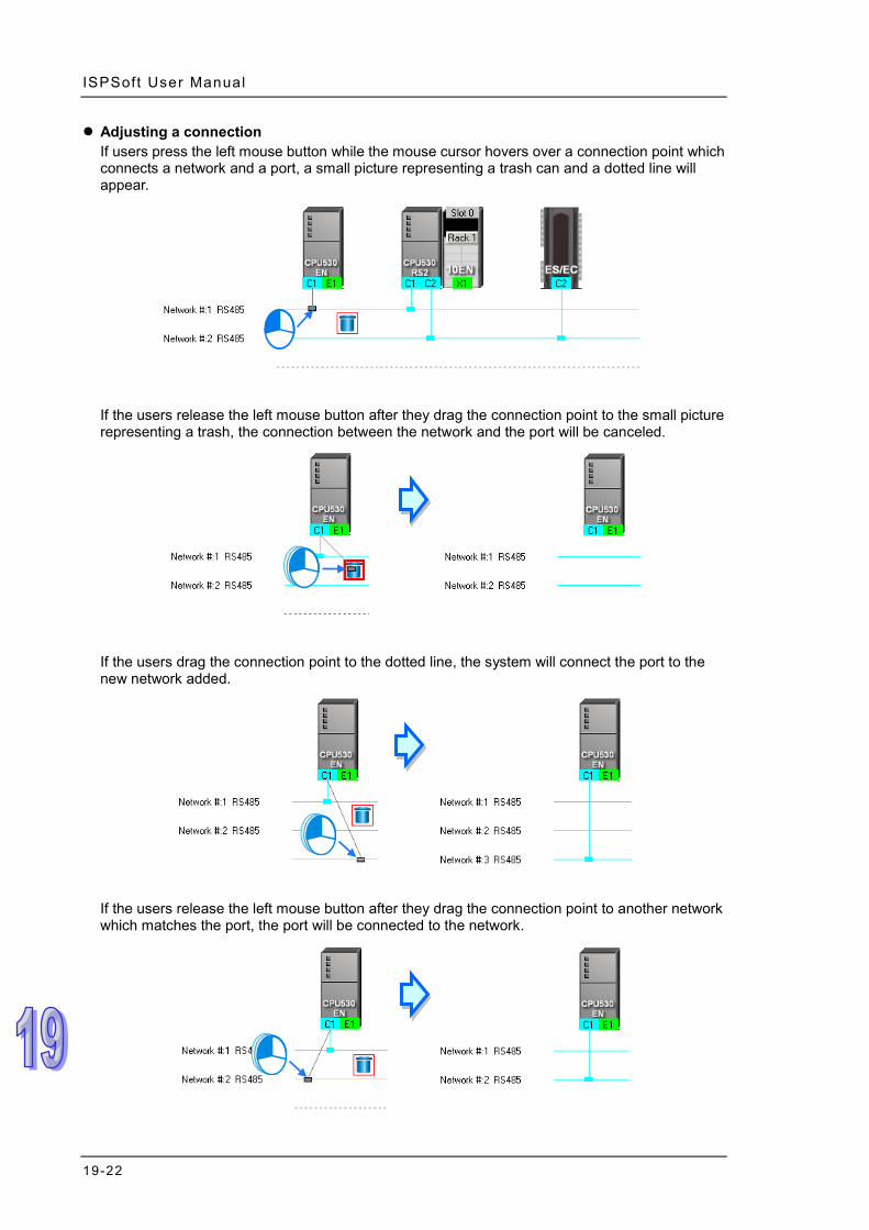
ISPSoft User Manual
19-22
Adjusting a connection If users press the left mouse button while the mouse cursor hovers over a connection point which connects a network and a port, a small picture representing a trash can and a dotted line will appear.
If the users release the left mouse button after they drag the connection point to the small picture representing a trash, the connection between the network and the port will be canceled.
If the users drag the connection point to the dotted line, the system will connect the port to the new network added.
If the users release the left mouse button after they drag the connection point to another network which matches the port, the port will be connected to the network.

Chapter 19 Network Conf igurat ion and Data Exchange
19-23
Deleting a single network by means of a context menu After users right-click a network, and click Delete the Network on the context menu, the network and the lines connected to the network will disappear.
Deleting several devices or several networks
Users can select several objects by holding down Shift on the keyboard. Besides, the users can select multiple devices by dragging a selection net around them, or selecting all the objects in the working area by pressing Ctrl+A on the keyboard.
After the users click Delete Selections on the Edit menu, click on the toolbar, or press Delete on the keyboard, the objects selected will be deleted. However, the PLC for which a project is created and the modules connected to the PLC cannot be deleted. Besides, if a PLC is deleted, the modules connected to the PLC will also be deleted.

ISPSoft User Manual
19-24
19.2.4 Setting the Attributes of a Node/Network
After users deploy the nodes in the NWCONFIG window, the information about the nodes will put above the nodes. The information includes PLC names and node numbers. The attributes of the ports connected to networks are also displayed. If a port is an RS-485 port, a station address will be displayed. If a port is an Ethernet port, an IP address will be displayed. The information about a port will be shown if the port is connected to a network. If a port is not connected to any network, no information about the port will be shown. Besides, if a port of a network module is connected to a network, the information about the slot in which the network module is installed, and the information about the backplane on which the network module is installed will be shown.
In addition to the information about the nodes, the network numbers assigned to the networks and the network types of the networks are shown. If a network is an Ethernet network, the subnet mask assigned to the ports connected to the network will be shown.
If the ports connected to an Ethernet network are not in the same domain, or are not assigned the same subnet mask, a warning sign will appear. If the ports connected to an Ethernet network are not assigned the same subnet mask, the strictest subnet mask will be shown.
The ports connected to the Ethernet network are not assigned the same subnet mask.
The ports connected to the Ethernet network are not in the same domain.

Chapter 19 Network Conf igurat ion and Data Exchange
19-25
Setting the attributes of a node There are two ways to open the Device Information window. (a) After users double-click a PLC, the Device Information window will appear. The users can
also open the Device Information window by right-clicking the PLC, and clicking Device Information on the context menu.
(b) After users double click a module, the Device Information window will appear. The users can also open the Device Information window by right-clicking the module, and clicking Module Information on the context menu.
In the Device Information window, there are two tabs. The page displayed in the window depends on the device selected.
If the device selected is the AH500 series CPU module for which a project is created, or a module connected to the AH500 series CPU module for which a project is created, most boxes in the Device Information window are gray. The attributes of the device can only be modified by

ISPSoft User Manual
19-26
means of HWCONFIG. If the device selected is a DVP series PLC, a device which is added to the working area, the users can set the attributes of the device. Please refer to section 19.1.2 for more information about the meaning of attributes. In the Device Information window, a port is related to a Connected Network drop-down list box. If a port can be connected to several networks, the network numbers assigned to these networks will be on the drop-down list which appears after the users click in the Connected Network drop-down list box related to the port. The users can select a network number on the drop-down list. If None is selected, the port will not connect to any network. This function is similar to the adjustment of a connection described in section 19.2.3.
In the page for a module, the users can select a rack number in the Rack Number drop-down list box, and a slot number in the Slot Number drop-down list box.
After the users complete the setting of the attributes of a node, and click OK in the Device Information window, the attributes of the node will be updated immediately.

Chapter 19 Network Conf igurat ion and Data Exchange
19-27
Setting the attributes of a network After users double-click a network, the Network Information window will appear. The users can also open the Network Information window by right-clicking the network, and clicking Network Information on the context menu.
In the Network Information window, the users can select a network number which is not assigned to any network in the Network Number drop-down list box. Besides, the users can type a comment in the Comment box. After the users complete the setting of the attributes of the network, and click OK in the Network Information window, the attributes of the network will be updated immediately.
If the users unselect the Visible checkbox in the Network Information box, the network and the devices connected to the network will become invisible, the other devices connected to the other networks will still be displayed, and the lines connected to the network will become dotted lines. Please refer to section 19.2.5 for more information about hiding/displaying devices or networks.

ISPSoft User Manual
19-28
19.2.5 Hiding/Displaying Devices or Networks
Users can hide/display devices or networks in the working area. The number of devices visible and the total number of devices are displayed in the status bar. Besides, if a dotted line is connected to a port of a device, the port is connected to an invisible network.
Only displaying the objects connected to a device
After users right-click a node, and click Only Show Directly Connected Devices on the context menu, only the network and the devices which are connected to the node will be displayed.
Only displaying the devices connected to a network
After users right-click a network, and click Only Show This Network on the context menu, only the devices connected to the network will be displayed.

Chapter 19 Network Conf igurat ion and Data Exchange
19-29
Hiding a network and the devices connected to the network After users unselect the Visible checkbox in the Network Information box, the network and the devices connected to the network will become invisible, but the other devices connected to the other networks will still be displayed,
Hiding/Displaying the devices which are not connected to any networks
If users want to hide/display the devices which are not connected to any networks, they can right-click the working area, point to Unconnected Devices Visible on the context menu, and click Hide/Show. This operation affects the devices in the present working area. It does not affect the devices which will be added latter.

ISPSoft User Manual
19-30
Setting the display states of all the objects at the same time Users can set the display states of all the devices at the same time. Click Device & Network Visible Settings on the View Menu, or on the toolbar.
Select networks which will be displayed in the Networks section in the Devices & Networks Visible Settings window. The networks which are not selected will not be displayed in the working area. If the users select the Select All checkbox, all the networks in the Networks section will be selected. If the users unselect the Select All checkbox, all the networks in the Networks section will be unselected. In the Unconnected Devices section, the users can set the display states of the devices which are not connected to any networks. This operation affects the devices in the present working area. It does not affect the devices which will be added latter.
Displaying all the objects
After users right-click the blank in the working area, click Show All Devices and Networks on the context menu, the devices and the networks which are hidden will be displayed.

Chapter 19 Network Conf igurat ion and Data Exchange
19-31
19.2.6 Correct Network Architecture
After users click Check Routing Information on the Edit menu, or on the toolbar, the system will check whether the network architecture the users create is correct, and the check result will be displayed in the message display area.
The system checks the ports which are connected to networks. It checks whether the information about the nodes and the information about the networks are correct. Specifically, it checks the node numbers, the RS-485 station addresses, and the IP addresses in the working area. At first glance, the network architecture in the figure above seems to be incorrect in that the node number assigned to AH-01 is the same as the node number assigned to AH-03, the node number assigned to AH-02 is the same as the node number assigned to AH-04, the RS-485 station address assigned to AH-01 is the same as the RS-485 station address assigned to AH-02, the RS-485 station address assigned to AH-03 is the same as the RS-485 station address assigned to AH-04, the IP address assigned to AH-01 is the same as the IP address assigned to AH-03, and the IP address assigned to AH-02 is the same as the IP address assigned to AH-04. The users can view a network at a time by means of a skill introduced in section 19.2.5. The users have to make sure that the node number, the RS-485 station address, and the IP address which are assigned to a node are not the same as the node number, the RS-485 station address, and the IP address which are assigned to another node. The

ISPSoft User Manual
19-32
message in the message display area in the figure above indicates that the network architecture in the working area is correct. Node number
In principle, the node number assigned to a node in a network cannot be the same as the node number assigned to another node in the network. If users view a network at a time, they can check whether the node number assigned to a node connected to a network is the same as the node number assigned to another node connected to the network.

Chapter 19 Network Conf igurat ion and Data Exchange
19-33
RS-485 station address In principle, the RS-485 station address of a port in a network cannot be the same as the RS-485 station address of another port in the network. If users view an RS-485 network at a time, they can check whether the RS-485 station address of a port in a network is the same as the RS-485 station address of another port in the network.
IP address
The IP address of a port in a network cannot be the same as the IP address of another port in the network. If users view an Ethernet network at a time, they can check whether the IP address of a port in a network is the same as the IP address of another port in the network.

ISPSoft User Manual
19-34
19.2.7 Downloading Routing Tables
After users make sure that the network architecture they create is correct, they can download the routing tables produced to PLCs. The routing data stored in a PLC is data related to the PLC itself, and therefore the routing tables downloaded to nodes are different. The users have to download the routing tables produced to nodes in the working area. The users can download the routing tables produced to nodes one by one, or download the routing tables produced to nodes at the same time. If the users want to download the routing tables produced to nodes, the Routing Mode checkbox in the Select a Driver window must be unselected. Please refer to section 19.1.3 for more information. Single node
The users have to select a node in the working area. Only AH500 series CPU modules support routing. If the users select a device which is not an AH500 series CPU module, a routing table cannot be downloaded to the device.
After the users click Download to PLC on the PLC menu, or on the toolbar, the Optional Download window will appear. The users can also open the Optional Download window by right-clicking the device they select, and clicking Download to PLC on the context menu. After the users select the Routing Table checkbox in the Optional Download window, and click OK, a routing table will be downloaded to the device.
Multiple nodes
The users have to select an Ethernet network in the working area. If the actual connection is consistent with the setting in NWCONFIG, parameters can be downloaded to the nodes connected to the Ethernet network. If the users want to download the routing tables produced to multiple devices connected to the Ethernet network, the connection type that the driver selected

Chapter 19 Network Conf igurat ion and Data Exchange
19-35
in the Driver Name drop-down list box in the Select a Driver window uses must be Ethernet. Please refer to section 19.1.3 for more information.
After the users click Download to PLC on the PLC menu, or on the toolbar, the Optional
Download window will appear. After the users select the Routing Table checkbox in the Optional
Download window, and click OK, the routing tables produced will be downloaded to the nodes
connected to the Ethernet network.
Additional remark If the parameters related to an Ether Link or a PLC Link can be downloaded to the object selected, users can select the Ether Link checkbox or the PLC Link (Reset) checkbox in the Optional Download window. If a checkbox in the Optional Download window is gray, the checkbox cannot be selected. Please refer to the following sections for more information about Ether Links and PLC Links. Besides, the routing data stored in a PLC is data related to the PLC itself. The users cannot upload the routing data stored in a PLC. The system does not provide the function of uploading routing data.
19.2.8 Testing Routing
After the routing tables produced are downloaded, users can test routing by means of a function provided by NWCONFIG. The steps of testing routing are as follows. (1) The users have to make sure that all the nodes are wired according to the configuration in
NWCONFIG, and operate normally. The setting of the devices has to be consistent with the setting in NWOCNIFG. In the Select a Driver window, the users have to select the Routing Mode checkbox, and select a device in the First Station drop-down list box. Please refer to section 19.1.3 for more information about setting communication.

ISPSoft User Manual
19-36
(2) After the users select the destination device toward which packets are relayed, they have to click on the toolbar, or Routing Detect on the PLC menu.
The users can also right-click the destination device, and then click Routing Detect on the context menu.
(3) After Routing Detect is clicked, the display of the network architecture in the working area will
change, and the Routing detect status window will appear. The way in which the node which is designated as the first station is connected to the computer is also shown in the working area. Please see the red circle in the figure below.

Chapter 19 Network Conf igurat ion and Data Exchange
19-37
(4) After the detection is complete, the detection result will be shown in the working area.
Additional remark If the detection fails, the users have to make sure of the following points. (a) The users have to make sure that the IP addresses and the station addresses which are
assigned to the devices and the communication setting in the devices are consistent with the setting in NWCONFIG. If AH500 series CPU modules or AH500 series modules are used, the users have to make sure that the parameters in the AH500 series CPU modules in HWCONFIG or the parameters in the AH500 series modules in HWCONFIG are set correctly, and downloaded to the AH500 series CPU modules or the AH500 series modules successfully. If DVP series PLCs or DVP series modules are used, the users have to make sure that the communication parameters in the related registers are correct. If other devices are used, the users have to refer to manuals for the usage of these devices, and make sure that the communication parameters in these devices are correct.
(b) The users have to make sure that all the network connection is consistent with the setting in NWCONFIG. They also have to make sure that every node is connected to a network correctly, and operates normally.
(c) Please refer to section 19.1.3, and make sure that the communication setting is correct.
19.3 Constructing a PLC Link A PLC Link is a network mechanism for data exchange performed through an RS-485 cable. If there are several nodes in an RS-485 network, users can create a mechanism for data exchange in the network. If the parameters which are set are downloaded to the PLC which functions as a master station, the system of the PLC will perform data exchange through special relays and special registers when the PLC runs. A PLC Link is a master/slave model. There is only one master station in an RS-485 network, and the other stations which are slave stations passively receive reading/writing commands from the master

ISPSoft User Manual
19-38
station. The slave stations cannot exchange data. They have to exchange data through the master station.
19.3.1 Opening the PLC Link Table Editor Window Before creating a PLC Link, users have to make sure that all the network setting is correct. Please use one of the methods described below. Method 1
After the users select a network, they have to click Construct PLC Link on the Tools menu, or on the toolbar.
Method 2
Double-click a network.

Chapter 19 Network Conf igurat ion and Data Exchange
19-39
Method 3 Right-click a network, and then click Construct PLC Link on the context menu.
After the users use one of the methods described above, the PLC Link Table Editor window will be opened. The PLC Link Table Editor window leads the users to construct a PLC Link step by step. The steps of constructing a PLC Link are designating a port as a master station, setting communication parameters, and creating a data exchange table. The system leads the users to the operation screen displayed last time as soon as the PLC Link Table Editor window is opened. As a result, if the users construct a PLC Link for the first time, the screen displayed will lead the users to accomplish the first step. Besides, a PLC Link is executed through special relays and special registers. The construction tool introduced here is just a friendly user interface which helps users download the parameters related to a PLC Link to the related special relays and the related special registers. The exact execution of a PLC Link depends on the special relays and the special registers in a PLC. To ensure that the PLC Link constructed can operate normally, users have to make sure of the functions of the PLCs and the limitations of the PLCs with regard to the PLC Link.
19.3.2 Designating a Port as a Master Station (Step 1)
Only an AH500 series CPU module, an AH500 series module, a DVP series PLC, or a DVP series module can be designated as the master station. Not all ports of a PLC or a module can be designated as the master station, and therefore users have to read the usage of the PLC or the module before they designate a port as the master station. Besides, if some of the ports of a node can be designated as masters, the PLC which is a part of the node will execute the PLC Link no matter what port is designated as a master station.

ISPSoft User Manual
19-40
(1) Select a port of a node in the Master Device drop-down list box. Only the ports which can be designated as master stations are listed.
(2) After users click , the system will ask the users whether they want to upload the
setting related to a PLC Link through the master station. If the users click No, they will be led to the second step. If the users click Yes, the setting related to a PLC Link in the PLC which is a part of the node will be uploaded through the master station, and the data uploaded will be displayed on the screen after the users are led to the third step. Before the users upload the data, they have to make sure of the following points. (a) The users have to make sure that the computer and the port designated as a master
station are connected by means of a communication cable. (b) The users have to make sure that a driver has been created correctly, and the driver is not
in the status of ERROR. (c) The users have to make sure that they have completed the communication setting in
NWCONFIG.
19.3.3 Setting Communication Parameters (Step 2)
After the system leads users to the second step, the users have to set the communication parameters in the PLC Link Table Editor window. The parameters uploaded through the master station are displayed at the left part of the window. The setting of the communication parameters of all the slave stations in the same network must be the same as the setting of the communication parameters of the master station. If no parameters are uploaded, “Unknown” will be shown in the boxes at the left part of the window. If the station address uploaded is different form the station address assigned o the master station, the Station Address box will become red.

Chapter 19 Network Conf igurat ion and Data Exchange
19-41
Transfer Capacity Mode
The users can set 16 data exchange groups or 32 data exchange groups, depending on the model selected. The users can select a maximum data length in the Transfer Capacity Mode section. Besides, the maximum data length which can be set varies with the PLC which is designated as a master station. Please refer to manuals for more information. If an AH500 series CPU module or an AH500 series module is designated as a master station, the 450 words (AH Only) option button in the Transfer Capacity Mode section can be selected. Only AH500 series CPU modules allow 450-word data to be exchanged. As a result, if the 450 words (AH Only) option button in the Transfer Capacity Mode section is selected, the DVP series PLCs and the other devices cannot execute a PLC Link.
Hold the RS485 Setting
Generally speaking, the communication parameters in a DVP series PLC will be restored to the default values if the DVP series PLC is turned on after a power failure. However, if the Hold the RS485 Setting checkbox is selected, the communication parameters stored will be loaded again if a DVP series PLC runs after it is stopped. Please refer to manuals for more information about the communication parameters in DVP series PLCs.
Synchronic R/W Generally speaking, a master station sends a writing command and a reading command to a slave station separately. If the Synchronic R/W checkbox is selected, the master station can

ISPSoft User Manual
19-42
complete reading and writing simultaneously by means of a specific Modbus function code (the hexadecimal code 17), and the efficiency of data exchange is increased. However, the users have to make sure that the devices involved in data exchange support the Modbus function code before they select the Synchronic R/W checkbox. If the devices do not support the Modbus function code, the Modbus code cannot be identified, and the reading/writing of data will fail after they receive the commands from the master station.
Run PLC Link after downloading If the Run PLC Link after downloading checkbox is selected, the PLC Link constructed will be enabled after the PLC Link constructed is downloaded to the PLC connected to the computer.
Interval Time (ms) The users can specify how often the master station sends a command.
After the users click , the system will lead the users to the next step. If the users click , the system will lead the users to the previous step.
19.3.4 Creating a Data Exchange Table (Step 3)
19.3.4.1 Introduction of a Data Exchange Table
The table below is a data exchange table. When a PLC Link is executed, the master station sends reading/writing commands to the slave stations according to the data exchange table created.

Chapter 19 Network Conf igurat ion and Data Exchange
19-43
Column Description
Serial Number (#)
The data exchange groups in the data exchange table in the PLC Link Table Editor window are numbered. Users can set 16 data exchange groups or 32 data exchange groups, depending on the model selected.
Station Addr.
The slave station address which belongs to a data exchange group is indicated. A station address can belong to several data exchange group. Besides, the station address 0 represents an undefined slave station, and is not a broadcast station address.
R/W R: The master station reads the data in devices in a slave station. W: The master station writes data into devices in a slave station.
Master Device Data The range of devices which are used in the master station is indicated.
<=> <=: The master station reads the data in devices in a slave station. =>: The master station writes data into devices in a slave station.
Slave Device Data
The devices which are used in a slave station are indicated. If a slave station is a user-defined Modbus device, the devices used will be represented by hexadecimal addresses.
Length A data length is indicated. A length indicates the number of devices used.
Status Users can decide whether to involve a data exchange group in data exchange. If a data exchange group is set incorrectly, the data exchange group will not be involved in data exchange. If a data exchange group is not involved in data exchange, the related data will be on a gray ground.
Device Type The device types shown are consistent with the device names shown in the working area in NWCONFIG. If a slave station address is assigned to a network module, the name of the PLC to which the network module is connected will be shown. Besides, if a slave station is undefined, it is unknown.
The figure below is an example of a data exchange table. Group #1, group #2, group #4, and group #5 are involved in data exchange. Please refer to the table below for more information.

ISPSoft User Manual
19-44
Serial number Description
#1 The master station reads the data in D2500~D2599 in the slave station whose station number is 2, and stores the data in D3000~D3099 in itself. Meanwhile, the data in D3100~D3149 in the master station is written into D2600~D2649 in the slave station.
#2
The master station reads the data in M3000~M3159 in the slave station whose station number is 2, and stores the data in M3000~M3159 in itself. Meanwhile, the data in M3200~M3359 in the master station is written into M3200~M3359 in the slave station.
#4
The master station reads the data in 16#1000~16#1018 in the slave station whose station number is 3, and stores the data in D3400~D3424 in itself. Meanwhile, the data in D3500~D3524 in the master station is written into 16#1025~16#103D in the slave station.
#5
The master station reads the data in D3000~D3099 in the slave station whose station number is 6, and stores the data in D3600~D3699 in itself. Meanwhile, the data in D3700~D37999 in the master station is written into D3100~D3199 in the slave station.
Additional remark If “Disabled” appears in the Status cell for a data exchange group, the data exchange group will not be involved in data exchange, and the system will ignore the setting in other cells for the data exchange group. Besides, if the setting of a data exchange group becomes incorrect after a modification, “Disabled” will appear in the Status cell for the data exchange group.
19.3.4.2 Setting a Data Exchange Group
If users want to set the parameters for a data exchange group, they can double-click the data exchange group in the data exchange table in the PLC Link Table Editor window.

Chapter 19 Network Conf igurat ion and Data Exchange
19-45
Linked Device The users can select a slave station address which belongs to this data exchange group. The device type displayed in the Device Type box is a model name displayed in the working area in NWCONFIG. If the slave station address selected is assigned to a port of a network module, the name of the PLC to which the network module is connected will be shown in the Device Type box. If the slave station address selected is undefined, or is not involved in the PLC Link constructed, “Unknown” will be displayed in the Device Type box. Besides, the station address assigned to the master station cannot be selected, and a slave station address can belong to several data exchange groups.
Linked Status
After the users select a slave station address which can be used, they can select the Disable option button, or the Enable option button in the Linked Status section.
Read
The users can select a device type, type a starting address, and type a data length in the Master Parameter Setting section. They can select a device type, and type a stating address in the Slave Parameter Setting section. Generally speaking, the device types selected in the Read section must be the same, and do not have to be the same as the device types selected in the Write section.
Write
The users can select a device type, type a starting address, and type a data length in the Master Parameter Setting section. They can select a device type, and type a stating address in the Slave Parameter Setting section. Generally speaking, the device types selected in the Write section must be the same, and do not have to be the same as the device types selected in the Read section.
The data in a group of devices can be written into several different groups of devices, but the data in different groups of devices are not allowed to be stored in the same group of device. Take the figure above for example. The data in D3100~D3149 in the master station can be written into different slave stations, but D3000~D3099 in the master station cannot receive the data in devices other than D2500~D2599 in the slave station whose station address is 2. Besides, the device types selected in the Read/Write section must be the same. However, the limitation on the setting of a data exchange

ISPSoft User Manual
19-46
group varies with the master station/slave station selected or the communication parameters selected.
Related setting Description The 450 words (AH Only) option button in the Transfer Capacity Mode section is selected.
Only AH500 series CPU modules allow 450-word data to be exchanged. As a result, if the 450 words (AH Only) option button in the Transfer Capacity Mode section is selected, the DVP series PLCs and the other devices cannot execute a PLC Link. The users can only select M devices, D devices, or L devices in the Read/Write section. The device types selected in the Read/Write section do not have to be the same.
The 16 words option button in the Transfer Capacity Mode section is selected.
If the master station selected is a DVP series PLC, the 16 words option button in the Transfer Capacity Mode section can be selected. If the 16 words option button in the Transfer Capacity Mode section is selected, the starting device address in the Read/Write section will be a certain special register, and the users can only specify a data length.
The slave station selected is a user-define device.
If the slave station selected is a Modbus device, the devices used will be represented by hexadecimal addresses, and the users can select word devices or bit devices.
The Synchronic R/W checkbox is selected.
If the 450 words (AH Only) option button is not selected, the users can only select D devices in the Read/Write section after the Synchronic R/W checkbox is selected.
19.3.4.3 Consistency Between a Data Exchange Table and the Network Created in NWCONFIG
The device types shown in the data exchange table in the PLC Link Table Editor window are consistent with the device names shown in the working area in NWCONFIG. Besides, if a slave station address is assigned to a port of a network module, the name of the PLC to which the network module is connected will be shown.

Chapter 19 Network Conf igurat ion and Data Exchange
19-47
If users change the model to which a station address is assigned in NWCONFIG after a PLC Link is constructed, the new model name appearing in the Device Type cell for the station address will be in red, and “Disabled” will appear in the Status cell for the station address. The users have to check whether the setting is correct. If the setting is incorrect, the users have to modify the incorrect parts. After the users modify the incorrect parts, they can select the Enable option button in the Linked Status section.
If the data uploaded from the master station which is an AH500 series CPU module is not consistent with the network created in NWCONFIG, the device types shown in the data exchange table in the PLC Link Table Editor window will still be consistent with the device names shown in the working area in NWCONFIG, the incorrect device types will be in red, and “Disabled” will appear in the Status cell for the incorrect device types. The users have to check whether the setting is correct. If the setting is incorrect, the users have to modify the incorrect parts. After the users modify the incorrect parts, they can select the Enable option button in the Linked Status section.
The device types in the data exchange table in the PLC Link Table Editor window cannot be stored in a DVP series PLC, and therefore the users do not know whether the data uploaded from the DVP series PLC is consistent with the network created in NWCONIFG. The device types shown in the data exchange table in the PLC Link Table Editor window is consistent with the device names shown in the working area in NWCONFIG. If the device ranges set for a model is incorrect, “Disabled” will appear in the Status cell for the model. The users have to modify the incorrect parts. After the users modify the incorrect parts, they can select the Enable option button in the Linked Status section.

ISPSoft User Manual
19-48
The figure below is a data exchange table which is downloaded to a DVP-SV series PLC. The slave station to which the station address 1 is assigned is AHCPU530-EN.
The present network created in NWCONFIG is shown below. The slave station to which the station address 1 is assigned is a DVP-SV2 series PLC. After the data exchange table in the DVP-SV series PLC is uploaded, the device types shown in the data exchange table in the PLC Link Table Editor window will be consistent with the device names shown in the working area in NWCONFIG. The device ranges set for the DVP-SV2 series PLC is not within the device range for DVP-SV2 series PLC, and therefore “Disabled” appears in the Status cell for the DVP-SV2 series PLC.
19.3.4.4 Managing a Data Exchange Table
There are buttons under the data exchange table in the PLC Link Table Editor window. Please refer to the table below for more information about the buttons. If users click , the system will lead the users to the previous step.

Chapter 19 Network Conf igurat ion and Data Exchange
19-49
Item Description
Export The data in the data exchange table can be exported as a CSV file. The users can edit the CSV file through Microsoft Excel. The CSV file can also be used as reference material for another development work.
Reset After the users click the button, the setting in the data exchange table will be restored to the initial setting.
Check Settings After the users click the button, the data exchange table will be checked.
Upload After the users click the button, the parameters related to a PLC Link in the master station will be uploaded.
Download After the users make sure that the setting of a PLC Link is correct, they can download the setting to the master station by clicking the button.
Monitor and Download
After the users make sure that the setting of a PLC Link is correct, they can download the setting to the master station. After the setting is downloaded to the master station, the Linked Machines Status window will be opened automatically.
Finish After the users click this button, the PLC Link Table Editor window will be closed. Before the PLC Link Table Editor window is closed, the system will ask the users whether they want to save the modifications they make.
During the execution of a PLC Link, the slave stations passively receive reading/writing commands from the master station. As a result, the parameters set in the data exchange table in the PLC Link Table Editor window are for the master station. If the users click Upload, the parameters related to a PLC Link in the master station will be uploaded. If the users click Download, the setting in the data exchange table in the PLC Link Table Editor window will be downloaded to the master station. Likewise, the master station will be monitored if the users click Monitor and Download. Before the users click Upload, Download, or Monitor and Download, they have to make sure that the device which is connected to the computer is the PLC which is designated as a master station, and the computer can communicate with the PLC normally. Please refer to section 19.1.3 for more information. 19.3.5 Monitoring a PLC Link
Before users monitor the PLC Link constructed, they have to make sure that the system is connect to the PLC which is designated as a master station normally. Please refer to section 19.1.3 for more information. After the users make sure that the PLC Link constructed is correct, they can click Monitor and Download under the data exchange table in the PLC Link Table Editor window to open the Linked Machines Status window. Besides, a PLC link can be executed normally only if the master station runs. As a result, the users have to make sure that the PLC which is designated as a master station runs before they monitor the PLC Link constructed.
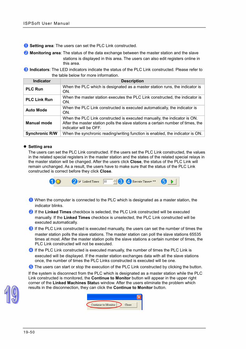
ISPSoft User Manual
19-50
Setting area: The users can set the PLC Link constructed.
Monitoring area: The status of the data exchange between the master station and the slave stations is displayed in this area. The users can also edit registers online in this area.
Indicators: The LED indicators indicate the status of the PLC Link constructed. Please refer to the table below for more information.
Indicator Description
PLC Run When the PLC which is designated as a master station runs, the indicator is ON.
PLC Link Run When the master station executes the PLC Link constructed, the indicator is ON.
Auto Mode When the PLC Link constructed is executed automatically, the indicator is ON.
Manual mode When the PLC Link constructed is executed manually, the indicator is ON. After the master station polls the slave stations a certain number of times, the indicator will be OFF.
Synchronic R/W When the synchronic reading/writing function is enabled, the indicator is ON.
Setting area
The users can set the PLC Link constructed. If the users set the PLC Link constructed, the values in the related special registers in the master station and the states of the related special relays in the master station will be changed. After the users click Close, the status of the PLC Link will remain unchanged. As a result, the users have to make sure that the status of the PLC Link constructed is correct before they click Close.
When the computer is connected to the PLC which is designated as a master station, the indicator blinks.
If the Linked Times checkbox is selected, the PLC Link constructed will be executed manually. If the Linked Times checkbox is unselected, the PLC Link constructed will be executed automatically.
If the PLC Link constructed is executed manually, the users can set the number of times the master station polls the slave stations. The master station can poll the slave stations 65535 times at most. After the master station polls the slave stations a certain number of times, the PLC Link constructed will not be executed.
If the PLC Link constructed is executed manually, the number of times the PLC Link is executed will be displayed. If the master station exchanges data with all the slave stations once, the number of times the PLC Links constructed is executed will be one.
The users can start or stop the execution of the PLC Link constructed by clicking the button. If the system is disconnect from the PLC which is designated as a master station while the PLC Link constructed is monitored, the Continue to Monitor button will appear in the upper right corner of the Linked Machines Status window. After the users eliminate the problem which results in the disconnection, they can click the Continue to Monitor button.

Chapter 19 Network Conf igurat ion and Data Exchange
19-51
Monitoring area When the PLC Link constructed is executed, the master station exchanges data with the slave stations. The status of the data exchange between the master station and the slave stations are displayed in this area.
The small pictures in the monitoring area indicate the status of the main station rather than the statuses of the slave stations. The small pictures in the monitoring area are described below.
The indicators on the small picture indicate the status of the data exchange group represented by the small picture.
The data exchange group represented by the small picture is not involved in data exchange.
The number corresponds to a serial number in the data exchange table. It represents the serial number of the data exchange group represented by the small picture.
The number corresponds to a slave station address in the data exchange table. It represents the slave station address which belongs to the data exchange group represented by the small picture.
Besides, the PLC Link error flags in an AH500 series CPU module are slightly different from the PLC Link error flags in a DVP series PLC, and therefore the small picture representing an AH500 series CPU module is different from the small picture representing a DVP series PLC. Please refer to the following table for more information.

ISPSoft User Manual
19-52
Master station
Small picture Description
AH500 series CPU module
If an error occurs when data in a slave station is read, the indicator will be ON.
If an error occurs when data is written into a slave station, the indicator will be ON.
When data exchange is performed, the indicator will be ON.
DVP series PLC
If an error occurs when data in a slave station is read, or an error occurs when data is written into a slave station, the indicator will be ON.
When data exchange is performed, the indicator will be ON.
After the users select a small picture, and right-click the small picture, they can click Write Register or Read Register on the context menu.
Write Register: The data written into the slave station specified is stored in registers in the
master station. For example, D3100~D3149 in the figure below are write registers.
Read Register: The data read from the slave station specified is stored in registers in the master station. For example, D3000~D3099 in the figure below are read registers.
After the users click Write Register or Read Register on the context menu, a correponding register monitoring table will appear.
A data format can be

Chapter 19 Network Conf igurat ion and Data Exchange
19-53
If the users double-click the Value cell for a device, or click Edit Value on the context menu after they right-click the Value cell, they can type a value in the Enter Value window. If the users double-click the Device Comment cell for a device, or click Edit Comment on the context menu after they right-click the Device Comment cell, they can make a comment on the device. The comments made are for the PLC Link constructed. They are not related to the comments on the devices in the program created in ISPSoft.
19.3.6 Important Points About Constructing a PLC Link
There is only one master station in an RS-485 network. If the node designated as a master station has several serial ports, the node cannot be designated as a master station in another RS-485 network, but can be designated as a slave station in another RS-485 network. In the figure below, C1 on the node AH-01 is designated as a master station in network #1, and TR1 on the node AH-01 is designated as a slave station in network #2. Besides, C1 on AH-01 and TR2 on AH-01 are connected to network #1. The station addresses assigned to these two ports are different. As a result, TR2 is allowed to be designated as a slaved station in network #1.
When a PLC Link is executed, the master station sends reading/writing commands to the slave stations according to the data exchange table created. Another master station which can send commands is not allowed to exist. If there is an unknown device which does not appear in
Users can type a value in the box.
Users can select a data format.
Users can display or hide the binary mode.
In the binary mode, users can set the states of the bits through the mouse.

ISPSoft User Manual
19-54
NWCONFIG and which can send commands in an RS-485 network, or there is a device which is designated as a slave station and which can send reading/writing commands in an RS-485 network, an error occurs when more than one device sends commands. As a result, after users create a network in NWCONIFG, they have to make sure that the actual connection is consistent with the network created in NWCONFIG.
Besides, if the users do not set the parameters related to a PLC Link in the original master station again before they designate another device as a master station, an error occurs when more than one device sends reading/writing commands. As a result, if the users want to designate another device as a master station, they have to make sure that the original master station does not execute the original PLC Link.
* In addition to the conditions mentioned above, users have to prevent two devices or more than two devices from
sending reading/writing commands simultaneously in any conditions.
19.4 Constructing an Ether Link
19.4.1 Introduction of an Ether Link
An Ether Link is a network mechanism for data exchange performed through an Ethernet connection. If there are several nodes in an Ethernet network, users can create a mechanism for data exchange in the network, and select a start mode. If the parameters which are set are downloaded to the PLCs in the network, the systems of the PLCs perform data exchange according to the start mode selected when the PLCs run. The users do not have to write a redundant program. Besides, only AH500 series CPU modules support Ether Links. A PLC Link is a master/slave model. There is only one master station in an RS-485 network, and the other stations which are slave stations passively receive reading/writing commands from the master station. Compared with a PLC Link, an Ether Link adopts a safer data request mechanism. It is the data demanding nodes in an Ethernet network that execute an Ether Link. An Ether Link is not a master/slave model. It allows a node to send reading commands which ask for data to other nodes. The nodes will send the data to the node after they receive the reading commands. Owing to the fact that a node cannot send writing commands to other nodes, the use of an Ether Link is safer than the use of a PLC Link. Besides, all the nodes in an Ethernet network can send reading commands through TCP/IP, and the system automatically manages the transmission of packets through TCP/IP. Compared with a PLC Link, an Ether Link is more efficient. Please refer to the example below for more information. If users want to create an Ether Link shown below, they have to create a data exchange table for the two data request nodes AH-01 and AH-02. (a) AH-01 reads the data in D100~D109 in AH-02, and stores the data in D0~D9 in itself. (b) AH-02 reads the data in D200~D219 in AH-01, and stores the data in D110~D129 in itself.

Chapter 19 Network Conf igurat ion and Data Exchange
19-55
An Ether Link is based on a network. If a node is connected to several networks, users can set several groups of parameters related to Ether Links for the networks. As a result, there may be several groups of parameters related to Ether Links in a PLC. Owing to the fact that an Ether Link is not a master/slave model, each node in a network can be a data demanding node and a data supply node at the same time. In the first piece of data in the table above, AH-01 is a data requiring node, and AH-02 is a data providing node. In the second piece of data in the table above, AH-01 is a data providing node, and AH-02 is a data requiring node.
19.4.2 Opening the Ether Link Configuration Window
Before users construct an Ether Link, they have to make sure that a network is set correctly. There are three ways to open the Ether Link Configuration window. Method 1
After the users select a network, they have to click Construct Ether Link on the Tools menu, or on the toolbar.

ISPSoft User Manual
19-56
Method 2 Double-click a network.
Method 3
Right-click a network, and then click Construct Ether Link on the context menu.
The Ether Link Configuration window is shown below.
Node list: After the users click a node, the node and the nodes of which the node demands data will be shown in the display area.

Chapter 19 Network Conf igurat ion and Data Exchange
19-57
Display area: The information about a node and the nodes of which the node demands data is displayed in this area.
Information area: The users can click the Message tab, the Table tab, or the Error Log tab. A node shown in the display area in the figure above is described below.
The information is composed of a node number, a PLC name, and a model name.
The IP address assigned to AH500 series CPU module is 192.168.1.2. The start mode of the Ether Link constructed is Always Run.
The IP address assigned to the module installed in slot 0 is 192.168.1.3. The start mode of the Ether Link constructed is Always Stop.
>1< in the D block indicates that the D block demands data of node 1. The numbers at the left side of the D block indicate that the data demanded of node 1 will be stored in D110~D119 in node 2. The color assigned to the D block depends on the node number in the D block. Owing to the fact that there is not any information in the M block and the L block, the M block and the L block does not demand any data of other devices.
19.4.3 Creating and Managing a Data Exchange Table
If users want to create a data exchange table, they have to click the Table tab in the information area. The node which is selected on the node list is shown in the upper left corner of the information area. The data in the table is related to the node selected.
If the users click , a new piece of data will be added to the table. A piece of data is composed of two parts. The left part of the data in the figure below indicates that the data demanding node AH-01 will store the data demanded in L0 in itself, and the right part of the data in the figure below indicates that the data supply node AH-02 will supply the data in L0 in itself.

ISPSoft User Manual
19-58
The steps of setting a data exchange group are as follows. (1) Select a node number in the # cell for the data demanding node. After the users select a node
number, the PLC name corresponds to the node number will be appear in the Device Name cell for the node number.
If the users select a specific node number rather than All Nodes on the node list, the data in the table will be related to the specific node number selected, and the fixed node number in the # cell for the data demanding node will be the specific node number selected on the node list.
(2) Select a device type in the Register cell for the data demanding node, and type an address in the Starting Address cell for the data demanding node.
(3) Select a node number in the # cell for the data supply node. The node number in the # cell for
the data demanding node cannot be the same as the node number in the # cell for the data supply node. After the users select a node number, the PLC name corresponds to the node number will be appear in the Device Name cell for the node number.
(4) Select a device type in the Register cell for the data supply node, and type an address in the
Starting Address cell for the data supply node. The device type selected in the Register cell for the data supply node does not have to be the same as the device type selected in the Register cell for the data demanding node.

Chapter 19 Network Conf igurat ion and Data Exchange
19-59
(5) Type a data length in the Size cell. A word is a unit. The maximum data length is 1900 words.
After the users type a data length, the device ranges in the Range cells will change according to the data length typed.
The users can create data exchange groups by following the steps described above. The device range in the Range cell for a data demanding node cannot overlap the device range in the Range cell for another data demanding node whereas the device range in the Range cell for a data supply node can overlap the device range in the Range cell for another data supply node. In other words, different demanders can ask for the same data, but different data cannot be store in the same block.
If the users want to delete a piece of data, they can click the piece of data, and click .
After the users click Export, the data in the data exchange table can be exported as a CSV file. The users can edit the CSV file through Microsoft Excel. The CSV file can also be used as reference material for another development work.

ISPSoft User Manual
19-60
After the users create a data exchange table, they can click Check Table Correctness on the Edit menu or on the toolbar if they wan to check the data set in the table. The check result will be displayed in the Message page.
19.4.4 Node List and Display Area
If users click All Nodes on the node list, all the nodes will be displayed in the display area, and all the data exchange groups set will be in the data exchange table under the display area. Besides, the devices in which the data demanded will be stored, and the data supply nodes are indicated in device blocks of the nodes in the display area. >2< in the D block in node 1 indicates that the D block demands data of node 2, and the numbers at the left side of the D block indicate that the data demanded of node 2 will be stored in D500~D509 in node 1. Likewise, >1< in the D block in node 2 indicates that the D block demands data of node 1, and the numbers at the left side of the D block indicate that the data demanded of node 1 will be stored in D1000~D1019 in node 1.
If the users click a specific node on the node list, the node and the nodes of which the node demands data will be shown in the display area, and the data in the data exchange table under the display will be related to the specific node selected. In the figure below, the dotted frame indicates that node 1 on the node list is selected, and the gray ground indicates that node 2 is a data supply node. Node 2 cannot be selected, and the information

Chapter 19 Network Conf igurat ion and Data Exchange
19-61
in the M block in node 2 indicates the data which will be supplied to node 1. Owing to the fact that node 3 does not supply any data to node 1, node 3 is not displayed in the display area. The numbers at the left side of the D block in node 1 indicates that the data demanded of node 2 will be stored in D500~D509 in node 1. <1> in the M block in node 2 indicates that the data in M1000~M1129 in node 2 will be supplied to 1.
If a specific node on the node list is selected, the node in the display area will be selected. After the users select All Nodes on the node list, they can click the information about a node in the display area if they want to select the node. If the users click a device block in a node, the node will not be selected. After a node is selected, a dotted frame will appear.
Once a node is selected, the node will be designated as a data demanding node. After the users click a device block in the node selected, a blue cursor will appear. After the users click a device block in another node (a data supply node), a green cursor will appear. The users can only click a device block in a data supply node. They cannot select the node, otherwise the node will be designated as a data demanding node.

ISPSoft User Manual
19-62
The users can click to add a new piece of data to the data exchange table. The data includes the data demanding node, the node number assigned to the data demanding node, the data supply node, the node number assigned to the data supply node, and the device types selected. The users can refer to section 19.4.3, and set the other cells.
19.4.5 Start Mode of an Ether Link
There are three start modes. Please refer to the table below for more information. Start mode Description
Always Stop During the operation of the PLC, no data exchange is performed. Always Run When the PLC runs, data exchange is performed.
SM Flag The performance of data exchange depends on a special relay in the PLC. After users select SM Flag, they can set the initial state of the related special relay.
*. Please refer to manuals or technical documents for more information about special relays related to Ether Links.
The execution of an Ether Link is based on the nodes in a network. If some of the ports that a node has are connected to a network, users can set the start modes of the ports separately. When the Ether Link constructed is executed, the system automatically distributes reading/writing work to the ports according to the start modes of the ports. If a port is disconnected, the system will pass the work belonging to the port to another port.
There are three ways to set the start mode of a node. Method 1
Right-click CPU information or module information, and then click Set Startup Mode on the context menu.

Chapter 19 Network Conf igurat ion and Data Exchange
19-63
Method 2 Double-click CPU information or module information.
Method 3
After the users click CPU information or module information, they have to click on the toolbar, or Set Startup Mode on the Edit menu.
After the users use one of the methods described above, the Starting Mode Setup window will appear. The page displayed in the window varies with the information selected. The users can click the tabs in the window. Select a mode in the Start Mode drop-down list box. If SM Flag is selected, the users can select an

ISPSoft User Manual
19-64
initial state in the Download State drop-down list box. After an initial state is selected, the users can click OK.
19.4.6 Downloading the Parameters Related to an Ether Link
After the parameters related to an Ether Link are set, users have to download the parameters to PLCs. The PLCs can perform data exchange after the parameters are downloaded. Single node
Only the data demanding setting related to the PLC selected, the start mode of the PLC selected, and the start modes of the modules connected to the PLC are downloaded. Before the users download the related parameters, they have to make sure that the system connects to the PLC normally, and they have completed the communication setting in NWCONFIG. Please refer to section 19.1.3 for more information. Method 1
Select a data demanding node, and then click on the toolbar. The users can also download the related parameters by selecting a data demanding node, clicking the PLC menu, pointing to Transfer, and clicking Download (Single PLC).
Method 2
Select a data demanding node, right-click the data demanding node, and click Download (Single PLC) on the context menu.

Chapter 19 Network Conf igurat ion and Data Exchange
19-65
Multiple nodes
The data demanding setting related to all the nodes, and the start modes of all the nodes are downloaded. Before the users download the related parameters, they have to make sure that all the PLCs and all the modules are connected to an Ethernet network, and can connect to NWCONFIG through Ethernet. The connection type that the driver selected in the Driver Name drop-down list box in the Select a Driver window uses must be Ethernet, otherwise the related parameters cannot be downloaded. Please refer to section 19.1.3 for more information. Method 1
Click the PLC menu, point to Transfer, and click Download (Multiple PLCs). The users can also download the related parameters by clicking on the toolbar.
Method 2
Select All Nodes on the node list, right-click All Nodes, and click Download (Multiple PLCs) on the context menu.
Additional remark If the parameters set include a node which does not demand any data, the node will not demand any data through the network specified after the parameters are downloaded to multiple nodes.

ISPSoft User Manual
19-66
19.4.7 Uploading the Parameters Related to an Ether Link
Users can upload the parameters related to an Ether Link in a PLC. Single node
Only the parameters related to an Ether Link in the node selected are uploaded. Before the users upload the related parameters in a PLC, they have to make sure that the system connects to the PLC normally, and they have completed the communication setting in NWCONFIG. Please refer to section 19.1.3 for more information. Method 1
Select a data demanding node, and then click on the toolbar. The users can also download the related parameters by selecting a data demanding node, clicking the PLC menu, pointing to Transfer, and clicking Upload (Single PLC).
Method 2
Select a data demanding node, right-click the data demanding node, and click Upload (Single PLC) on the context menu.
The node does not demand any data.
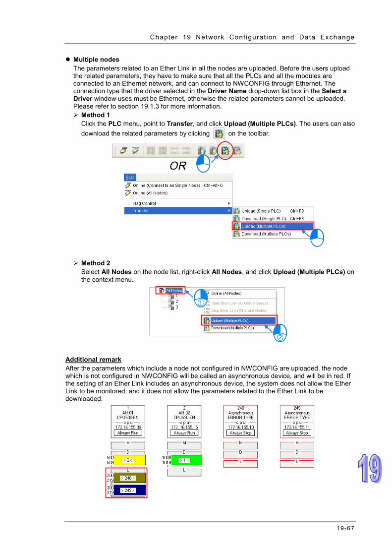
Chapter 19 Network Conf igurat ion and Data Exchange
19-67
Multiple nodes The parameters related to an Ether Link in all the nodes are uploaded. Before the users upload the related parameters, they have to make sure that all the PLCs and all the modules are connected to an Ethernet network, and can connect to NWCONFIG through Ethernet. The connection type that the driver selected in the Driver Name drop-down list box in the Select a Driver window uses must be Ethernet, otherwise the related parameters cannot be uploaded. Please refer to section 19.1.3 for more information. Method 1
Click the PLC menu, point to Transfer, and click Upload (Multiple PLCs). The users can also download the related parameters by clicking on the toolbar.
Method 2
Select All Nodes on the node list, right-click All Nodes, and click Upload (Multiple PLCs) on the context menu.
Additional remark After the parameters which include a node not configured in NWCONFIG are uploaded, the node which is not configured in NWCONFIG will be called an asynchronous device, and will be in red. If the setting of an Ether Link includes an asynchronous device, the system does not allow the Ether Link to be monitored, and it does not allow the parameters related to the Ether Link to be downloaded.

ISPSoft User Manual
19-68
19.4.8 Deleting Asynchronous Device
If the setting of an Ether Link includes asynchronous devices, the system does not allow the Ether Link to be monitored, and it does not allow the parameters related to the Ether Link to be downloaded. Users have to find out the reason for the existence of the asynchronous devices. If the network configuration in NWCONFIG is incorrect, the users have to modify the network configuration, and upload the parameters related to the Ether Link again. If the parameters uploaded are not applicable to the current network configuration, the users can delete the asynchronous devices. Select an asynchronous device which will be deleted, and then click Delete This Asynchronous Node on the Edit menu, or on the toolbar.
If the users want to delete all the asynchronous devices at the same time, they can click Synchronize All Nodes on the Edit menu, or on the toolbar.

Chapter 19 Network Conf igurat ion and Data Exchange
19-69
19.4.9 Enabling/Disabling the Online Monitoring Function In the Ether Link Configuration window, users can execute or test the Ether Link constructed by means of the online monitoring functions provided by NWCONFIG. The users can enable/disable the function of monitoring a single node/multiple nodes online. Enabling/Disabling Description
Single node
Function Enabling or disabling the function of monitoring the node selected online
Condition The users have to make sure that ISPSoft can connect to the PLC selected normally, and they have completed the communication setting in NWCONFIG.
Multiple nodes
Function Enabling or disabling the function of monitoring all the nodes online
Condition
The users have to make sure that all the nodes are connected to a network, and can connect to ISPSoft through Ethernet. The connection type that the driver selected in the Driver Name drop-down list box in the Select a Driver window uses must be Ethernet.
*. Please refer to section 19.1.3 for more information about the communication setting in NWCONFIG.
Before the users enable the online monitoring function, they have to make sure that all the nodes are connected according to the network framework created in NWCONFIG, and can operate normally. (a) Every node has been connected to a network according to the network framework created in
NWCONIFG. (b) The users have set the parameters for Ethernet ports of the nodes by means of HWCOFNIG,
and the parameters have been downloaded to the PLCs and the modules. The setting of the parameters must be consistent with the setting in NWCONFIG.
(c) The parameters related to an Ether Link have been downloaded to the PLC selected. (d) Every node is powered up, and can operate normally.
19.4.9.1 Enabling a Monitoring Function
Enabling the function of monitoring a single node Method 1
Select a data demanding node, and then click on the toolbar, or Online (Connect to a
Single node) on the PLC menu. When the data demanding node is monitored, on the toolbar is pressed.

ISPSoft User Manual
19-70
Method 2 Select a data demanding node, right-click the data demanding node, and click Online (Connect to a Single Node) on the context menu. When the data demanding node is monitored, on the toolbar is pressed.
Enabling the function of monitoring multiple nodes Method 1
Click Online (All Nodes) on the PLC menu, or on the toolbar.
Method 2
Select All Nodes on the node list, right-click All Nodes, and click Online (All Nodes) on the context menu.
Additional remark Before the system enters a monitoring mode, it checks whether the Ether Link constructed in the Ether Link Configuration window is consistent with the setting in the PLCs. If the Ether Link constructed in the Ether Link Configuration window is not consistent with the setting in the PLCs, the system will ask the users to download the related parameters again.

Chapter 19 Network Conf igurat ion and Data Exchange
19-71
19.4.9.2 Monitoring Statuses
After the system enters a monitoring mode, the node which is monitored will be colored on the node list.
Besides, the words and the pictures in the display area will indicate the execution status of the current Ether Link after the system enters a monitoring mode.
Status Description
Running/Stopping : The Ether Link constructed is
executed. : The Ether Link is not executed.
Operating status
: The Ether Link constructed is executed normally.
: The Ether Link constructed is not executed normally.
Start mode : Always Stop : Always Run : SM Flag
Data block
: The data exchange is being performed.
: The performance of the data exchange stops.
19.4.9.3 Disabling a Monitoring Function
Disabling the function of monitoring a single node Method 1
Select a data demanding node, and then click on the toolbar, or Offline (Disconnect from a Single node) on the PLC menu.

ISPSoft User Manual
19-72
Method 2 Select a data demanding node, right-click the data demanding node, and click Offline (Disconnect from a Single Node) on the context menu.
When the data demanding node selected is not monitored, on the toolbar is not pressed. If
another node is monitored, will be pressed.
Disabling the function of monitoring multiple nodes Method 1
Click Online (All Nodes) on the PLC menu, or on the toolbar.
Method 2
Select All Nodes on the node list, right-click All Nodes, and click Online (All Nodes) on the context menu.
19.4.10 Starting/Stopping the Execution of an Ether Link Online If the start mode of a node is SM Flag, users can make the node start or stop the execution of the Ether Link constructed by means of controlling the state of the related flag when the node is monitored online. If the node is not monitored online, the users cannot make the node start or stop the execution of the Ether Link constructed by means of controlling the state of the related flag. Users can make a single node/multiple nodes start or stop the execution of the Ether Link constructed. The conditions for making a single node/multiple nodes start or stop the execution of the Ether Link constructed are the same as the conditions for enabling/disabling the function of monitoring a single node/multiple nodes online. Please refer to section 19.4.9 for more information.

Chapter 19 Network Conf igurat ion and Data Exchange
19-73
19.4.10.1 Starting the Execution of an Ether Link
Making a single node start the execution of an Ether Link Method 1
If users want to make a node start the execution of the Ether Link constructed, they have to select the node, and click on the toolbar. They can also make the node start the execution of the Ether Link constructed by selecting the node, clicking the PLC menu, pointing to Flag Control, and clicking Start Ether Link (Single PLC).
Method 2
Select a node, right-click the node, and click Start Ether Link (Single PLC) on the context menu.
Making multiple nodes start the execution of an Ether Link Method 1
If users want to make all the nodes start the execution of the Ether Link constructed, they have to click the PLC menu, point to Flag Control, and click Start Ether Link (All Online Nodes). The users can also make all the nodes start the execution of the Ether Link constructed by clicking on the toolbar.

ISPSoft User Manual
19-74
Method 2
Select All Nodes on the node list, right-click All Nodes, and click Start Ether Link (All Online Nodes) on the context menu.
19.4.10.2 Stopping the Execution of an Ether Link
Making a single node stop the execution of an Ether Link Method 1
If users want to make a node stop the execution of the Ether Link constructed, they have to select the node, and click on the toolbar. They can also make the node stop the execution of the Ether Link constructed by selecting the node, clicking the PLC menu, pointing to Flag Control, and clicking Stop Ether Link (Single PLC).
Method 2
Select a node, right-click the node, and click Stop Ether Link (Single PLC) on the context menu.

Chapter 19 Network Conf igurat ion and Data Exchange
19-75
Making multiple nodes stop the execution of an Ether Link Method 1
If users want to make all the nodes stop the execution of the Ether Link constructed, they have to click the PLC menu, point to Flag Control, and click Stop Ether Link (All Online Nodes). The users can also make all the nodes stop the execution of the Ether Link constructed by clicking on the toolbar.
Method 2 Select All Nodes on the node list, right-click All Nodes, and click Stop Ether Link (All Online Nodes) on the context menu.
Additional remark If a node in the display area has several Ethernet ports, users can make a port start/stop the execution of the Ether Link constructed by means of clicking an item on the context menu which appears after they right-click the node. The execution of an Ether Link is based on the nodes in a network. If users make a port that a node has stop the execution of the Ether Link constructed, another node that the node has can still execute the Ether Link constructed.

ISPSoft User Manual
19-76
19.4.11 Monitoring Table and Error Log
After users double-click a data block, the Data Monitor window will appear. The users can view the values in the window. They cannot change the values in the window.
After users click the Radix cell for a device, they can select a method of representing the value in the device on the drop-down list.
The information about the data block which is monitored is displayed.
Users can type a device address in this box. After the users press Enter on the keyboard, they can easily view the device address in the window.
After a node is selected, the error log in the node will be displayed in the Error Log page. If the users select the Ether Link Error Filter checkbox, only the error log related to the Ether Link constructed will be listed. Besides, after the users click Renew, the error log in the node will be retrieved, and the error log retrieved will be displayed in the Error Log page. After the users click Clear, the error log in the Error Log page and the error log in the node will be cleared.

Chapter 19 Network Conf igurat ion and Data Exchange
19-77
If the node selected consists of a CPU module and a module, the error log in the Error Log page will be composed of the errors occurring in the CPU module and the errors occurring in the module. If an error code in the Error Log page corresponds to an error occurring in the module, the model name of the module will be displayed in the Module Type cell for the error code, the rack on which the module is installed will be indicated by the number in the Rack No. cell for the error code, and the slot in which the module is installed will be indicated by the number in the Slot No. cell for the error code. If an error code in the Error Log page corresponds to an error occurring in the CPU module, there will be no numbers in the Rack No. cell for the error code and the Slot No. cell for the error code.
19.5 Managing and Applying NWCONFIG
19.5.1 Saving Parameters and Printing a Network Framework If users want to save the parameters set in NWCONFIG, they can click Save on the File menu, or
on the toolbar. The parameters which can be saved are the network framework created in NWCONFIG, the parameters related to the PLC Links constructed, and the parameters related to the Ether Links constructed. After the saving of the parameters set in NWCONFIG is complete, an nw file whose primary filename is the project name/group name, and an nwsd file whose primary filename is the project name/group name will appear in the folder in which the project/group of projects is/are saved.
After the users click Print Preview on the File menu, or on the toolbar, the system will automatically open the Print Preview window, and the network framework that the users create in NWCONFIG will be displayed in the Print Preview window. Please refer to appendix C for more information.

ISPSoft User Manual
19-78
Before the users print the data related to a PLC Link or an Ether Link, they have to export the data as a CSV file. After the CSV file is opened in Microsoft Excel, they can print the data in the CSV file. 19.5.2 Downloading Parameters In the working area in NWCONFIG, users can download the routing tables produced to PLCs, the parameters related to the PLC Links constructed, the parameters related to the Ether Links constructed to the nodes.
19.5.2.1 Introduction of Parameters
Routing table The routing data stored in a PLC is data related to the PLC itself, and therefore the routing tables downloaded to nodes are different. Users have to download the routing tables produced to nodes in the working area.
Parameters related to a PLC Link The parameters related to a PLC Link can only be downloaded to the PLC designated as a master station. If the parameters related to a PLC Link are downloaded to a slave station, the related special relays and the related special registers in the slave station will be restored to the default setting. There is only one master station in a network. If users are not sure whether a device was designated as a master station, and whether the parameters related to a PLC Link was downloaded to the device, they have to download the parameters related to a PLC Link to the device.
Parameters related to an Ether Link The parameters related to an Ether Link must be downloaded to the data demanding nodes. However, the data exchange table stored in a PLC is a table related to the PLC itself. Besides, if the parameters set include a node which does not demand any data, the data in the node will be cleared after the parameter are downloaded to the node, and the start mode of the node will depend on the parameters after the parameters are downloaded to the node.

Chapter 19 Network Conf igurat ion and Data Exchange
19-79
19.5.2.2 Description of Downloading Parameters
If the users want to download parameters, the Routing Mode checkbox in the Select a Driver window must be unselected. Please refer to section 19.1.3 for more information. Single node
The users have to select a node in the working area.
After the users click Download to PLC on the PLC menu, or on the toolbar, the Optional Download window will appear. The users can also open the Optional Download window by right-clicking the device they select, and clicking Download to PLC on the context menu.
Multiple nodes
The users have to select an Ethernet network in the working area. After the users click Download to PLC on the PLC menu, or on the toolbar, the Optional Download window will appear. If the actual connection is consistent with the setting in NWCONFIG, parameters can be downloaded to the nodes connected to the Ethernet network.

ISPSoft User Manual
19-80
After the users follow the steps described above, the Optional Download window will appear. If a checkbox in the Optional Download window is gray, the checkbox cannot be selected. After the users select checkboxes in the Optional Download window, they can click OK.
19.5.3 Using Routing in ISPSoft After users create a network architecture in NWCONFIG, and download the routing tables produced to PLCs, they can download data to a device which is not directly connected to ISPSoft through routing, upload data from a device which is not directly connected to ISPSoft through routing, or monitor data in a device which is not directly connected to ISPSoft through routing. If the users want to use routing in ISPSoft, the devices used must be AH500 series CPU modules. In the figure below, the PLC which actually connects to the computer is AH-01. AH-03 can be monitored through routing.
(1) Users have to activate the project for AH-03.

Chapter 19 Network Conf igurat ion and Data Exchange
19-81
(2) Click the Tools menu, and then click Communication Settings….
(3) In the Communication Setting window, the users have to select the Routing Mode checkbox,
and select a device in the First Station drop-down list box. Generally speaking, the device which actually connects to the computer is the first station. If the computer connects to several devices, or connect to devices through Ethernet, the users have to designate a device as the first station according to the network framework created in NWCONFIG. Besides, if the Routing Mode checkbox is selected, the driver selected in the Driver drop-down list box must be a driver which can connect to the first station. After the users click OK in the Communication Setting window, AH-03 can be monitored through AH-01.
Additional remark Before users use routing, they have to create projects, configure hardware, and configure a network. Please refer to section 19.1.4 for more information. The users can also refer to section 19.1.3 for more information about the communication setting in NWCONFIG.

ISPSoft User Manual
19-82
MEMO
Chapter 20 Data Backup and Data Restoration
Table of Contents 20.1 Data Backup Memory Cards ................................................................20-2
20.1.1 Introduction of Data Backup Memory Cards .................................20-2 20.1.2 Using a Data Backup Memory Card .............................................20-2
20.2 Permanent Data Backup ......................................................................20-3 20.3 CARD Utility (for AH/AS Series) ..........................................................20-4
20.3.1 Introduction of CARD Utility ..........................................................20-4 20.3.2 Backup ..........................................................................................20-5 20.3.3 Restoration ...................................................................................20-9

ISPSoft User Manual
20-2
20.1 Data Backup Memory Cards
20.1.1 Introduction of Data Backup Memory Cards A DVP-EH2 series PLC can be used with DVP-256FM, a data backup memory card with a milky cover. A DVP-EH3 series PLC can be used with DVP-512FM, a data backup memory card with a black cover.
Install a memory card in a PLC, power the PLC up, unfold the PLC section in the project management area in ISPSoft, and double-click Connected Information. If ISPSoft is connected to the PLC normally, the system information about the PLC will be under the Connected Information section. The Data Backup Memory Card item indicates whether the memory card is enabled.
*. Please refer to section 2.4 for more information about communication setting.
20.1.2 Using a Data Backup Memory Card Users have to make sure that ISPSoft is connected to a PLC before they use the data backup memory card installed in the PLC. Click PLC Memory<=>Memory Card… on the PLC menu, select

Chapter 20 Data Backup and Data Restorat ion
20-3
the PLC Memory=>Memory Card option button or the Memory Card=>PLC Memory in the Type section in the PLC Memory<=>Memory Card window, and click OK.
*. Please refer to the related user manuals or technical documents for more information about data backup memory
cards, the models which are supported, and the firmware versions which are supported.
20.2 Permanent Data Backup There is flash memory in a DVP-EH2/DVP-EH2-L/DVP-EH3/DVP-EH3-L/DVP-SV/DVP-SV2 series PLC. The flash memory in a PLC is used to back up the data in the PLC. Please refer to manuals or documents for more information about the functions of flash memory. Users have to make sure that ISPSoft is connected to a PLC before they perform a data backup or a data restoration through ISPSoft. Click PLC Permanent Backup Setting on the Tools menu. In the PLC Permanent Backup Setting window, the users have to select the PLC=>Flash option button or the Flash=>PLC option button in the Flash Memory Read/Write section, select contents which will be transferred, select the Enable option button or the Disable option button in the Warning Message section. (A data restoration is automatically performed when the flat battery in a PLC causes a data loss. If the Enable option button in the Warning Message section is selected, a warning message appears when a data restoration is automatically performed.) After the setting in the PLC Permanent Backup Setting window is complete, the users can click OK.

ISPSoft User Manual
20-4
20.3 CARD Utility (for AH/AS Series)
20.3.1 Introduction of CARD Utility There are SD slots on AH/AS series CPU modules. Users can back up/restore data in an AH/AS series CPU module through the use of a memory card. Besides, ISPSoft provides CARD Utility for AH/AS series CPU modules. The users can back up/restore data in an AH/AS series CPU module or an ISPSoft project through a wizard. The program codes, the parameter settings, the hardware configurations, and the network configurations in an AH/AS series CPU module or an ISPSoft project can be backed up. The values in the devices in an AH/AS series CPU module can also be backed up. For the module software in the HWCONFIG, only ECAT Builder supports data backup and restoration. Please refer to operation manuals or technical documents for more information about the specifications of the SD cards which can be inserted into each series CPU modules, and the usage of the SD cards. As for the network configuration, the AH500 and DVP series will only back up data that is related to their own modules and ISPSoft CPU projects, such as Routing Table and Ether Link. Likewise, not all network configurations can be restored back to the ISPSoft project. Please refer to chapter 19 for more information about a network configuration. The functions supported by CARD Utility are described below. The diagram below is a flowchart. If users export data from an AH series CPU module as a backup file (*.dup), the data exported
can be saved in the memory card or in the computer. Users can also export the values in the devices in the AH/AS series CPU module. AS series does not support saving the exported file in the computer; users can only save the exported backup file in the memory card.
If users export an ISPSoft project of an AH500 series CPU module as a backup file (*.dup) can only be saved in the computer and the values in the devices of the AH500 series CPU module are not included. Data such as register editing (*.dvl), device status editing (*.dvb), file register editing (*.wft) of AS series and AHxxEMC can be seen as values in the device and can be exported and saved as backup files.
Users can put the backup file saved in the memory card inserted in a CPU module into the CPU module.
Users can import a backup file (*.dup) saved in a computer back to the AH series CPU module or restore the backup file to an ISPSoft project. For AS series, if the users choose to restore the backup file to an ISPSoft project, the system will automatically skip the values in the devices and the hardware configuration in the backup file. Data such as register editing (*.dvl), device status editing (*.dvb), file register editing (*.wft) of AS series and AHxxEMC can be seen as values in the device and can be imported back to restore the ISPSoft project.
For AHxxEMC series users can backup the G-Code files on the SD card of the CPU module to the computer. And when restoring, users can restore the G-Code files on the computer to the SD card of the CPU module or to the ISPSoft project.

Chapter 20 Data Backup and Data Restorat ion
20-5
After users double-click CARD Utility in the project management area, the system will open the CARD Utility window. Select the controller and PLC type from the drop-down list and then click Next to start.
20.3.2 Backup
If the backup source/backup destination is an CPU module or the memory card inserted in an CPU module, users have to make sure that ISPSoft is connected to the CPU module normally. Please refer to section 2.4 for more information. (1) Select the Backup (To DUP File) option button in the CARD Utility window, and then click
Next.
(2) Select a backup source, and then click Next.
After the users select the ISP Project (Compiled and saved) option button, they have to click , and select an isp file in the Open window. If the program in the isp file selected is not
compiled, a message appears when the isp file is backed up. Open the isp file with ISPSoft,

ISPSoft User Manual
20-6
compile the program in the isp file, and save the isp file. After the program in the isp file is compiled, the users can back up the isp file.
(3) After the users select the CPU (Need Connection) option button, they have to decide whether
to back up the values in the devices in the CPU module which is connected to ISPSoft.
(4) Select a backup destination. If the backup source is an ISPSoft project, the backup destination
must be a computer. a. If the Memory Card (PLC Side) option button is selected, the filename of the backup file
which will be produced will be AUTOEXEC.dup, and the path which points to the backup file will be Root directory of the memory card\AH500\SysDup\AUTOEXEC.dup for AH series and for AS series, it will be Root directory of the memory card\AS300\SysDup\AUTOEXEC.dup
b. If the PC (DUP File) option button is selected, the users have to click , select a folder

Chapter 20 Data Backup and Data Restorat ion
20-7
in the Save in drop-down list box in the Save As window, and type a filename in the File name box.
(5) For AHxxEMC series when the backup is from a CPU module to the computer, users can also
choose to backup the G-Code files on the SD card of the CPU module to the computer.
(6) When the backup source is selected to the ISPSoft Project, users can set up the PLC
password. The options are to set the password the same as the Project (If the password for the Project is not set, the same goes to the PLC password.), set a new PLC password, and do not set a PLC password. When the option “Setting new PLC password” is selected, the setup window will show up.

ISPSoft User Manual
20-8
(7) After the users make sure that the summary in the CARD Utility window is consistent with the
data backup which will be performed, they can click Execute.
Even if the users click Cancel to stop ISPSoft from performing the data backup in the process of backing up data in the CPU module onto the memory card inserted in the CPU module, the CPU module will still performs the data backup. The users can turn off the CPU module to stop the data backup from being performed. However, the backup file produced is not a complete backup file. As a result, the users have to delete the backup file from the memory card. If the Memory Card (PLC Side) option button is selected, the filename of the backup file which will be produced will be AUTOEXEC.dup, and the path which points to the backup file will be Root directory of the memory card\AH500\SysDup\AUTOEXEC.dup. If there is an old backup file in the memory card inserted in the CPU module which is connected to ISPSoft, the Warning window will appear. The users have to click Replace, Archive, or Cancel in the Warning window according to the message in the window.

Chapter 20 Data Backup and Data Restorat ion
20-9
If the data backed up is protected by passwords, these passwords will also be backed up.
Data backup Description
CPU module Memory card The data backed up includes the PLC ID and the PLC password set in the CPU module.
CPU module Computer
The system asks users to type a PLC ID and a PLC password. If the PLC ID and the PLC password typed are correct, the data backup will be performed. The data backed up includes the PLC ID and the PLC password.
ISPSoft project Computer The data backed up includes the program ID, the project password and the PLC password set while setting up the backup.
(8) After the data backup is performed, the users can click Home or Close in the CARD Utility
window.
20.3.3 Restoration
If the restoration source/restoration destination is an CPU module or the memory card inserted in an CPU module, users have to make sure that ISPSoft is connected to the CPU module normally. Please refer to section 2.4 for more information. (1) Select the Restore (From DUP File) option button in the CARD Utility window, and then click
Next.

ISPSoft User Manual
20-10
(2) Select a restoration source, click , and select a backup file.
If the Memory Card (PLC side) (Need Connection) option button is selected, the backup files in the memory card inserted in the CPU module connected to ISPSoft will be displayed in a window after is clicked. The users have to double-click a backup file in the window.

Chapter 20 Data Backup and Data Restorat ion
20-11
For AHxxEMC series when the backup is from a computer, the system will prompt to ask if you’d like to restore the G-Code in the computer and save the restored G-Code files to the SD card of the CPU module or ISPSoft project. If yes, the .nc files that share the same directory with the DUP files will be saved to the selected location.
*.G-Code filenames will be 100.nc~227.nc correspond to the G-Code items (100~227) in the SD card from the G-Code editor of the ISPSoft. For more information, please refer to chapter 21.
(3) Select a restoration destination, and then click Next.
a. If the users want to put the backup file selected into the CPU module which is connected to ISPSoft, they have to select the CPU (Need Connection) option button. If the restoration source is the memory card inserted in the CPU module connected to ISPSoft, the restoration destination must be the CPU module.
b. If the ISP Project option button is selected, the users have to click . After the users click , they have to specify a filename and a path. If the path specified point to a file which exists in the computer, the file will be overwritten after the data restoration is peformed.

ISPSoft User Manual
20-12
(4) After the users make sure that the summary in the CARD Utility window is consistent with the
data restoration which will be performed, they can click Execute.
If the users click Cancel in the process of restoring data to the CPU module, the data will not be completely restored. To prevent the CPU module from operating incorrectly, the users have to restore the CPU module to the factory setting if they do not perform the data restoration again. Besides, the CPU module will still performs the data restoration even if the users click Cancel in the process of restoring a backup file in the memory card inserted in the CPU module. The users can turn off the CPU module to stop the data restoration from being performed. If restoration source/restoration destination contains a password and an ID, the password and the ID will be processed as follows.

Chapter 20 Data Backup and Data Restorat ion
20-13
Data restoration Description
Memory cardCPU module
a. The ID in the backup file must be the same as the ID in the CPU module, otherwise the data restoration will not be performed.
b. If there is a PLC password in the CPU module, the password in the backup file must be the same as the PLC password in the CPU module. Otherwise the data restoration will not be performed.
c. If there is no PLC password in the CPU module, and there is a password in the backup file, the system will perform the data restoration, and the password in the backup file will become the PLC password in the CPU.
ComputerCPU module
a. The ID in the backup file must be the same as the ID in the CPU module, otherwise the data restoration will not be executed.
b. If there is a PLC password in the CPU module, the password in the backup file must be the same as the PLC password in the CPU module. Otherwise the data restoration will not be performed, and a message will appear.
c. If there is no PLC password in the CPU module, and there is a password in the backup file, the system will perform the data restoration, and the password in the backup file will become the PLC password in the CPU.
Computer ISPSoft project
While restoring, if the backup file is PLC password protected, users will be asked for the password to proceed. After restoration, the ID and the password in the backup file will become the program ID and the project password in ISPSoft project but the PLC ID and PLC password will not be saved to ISPSoft.
(5) After the data restoration is performed, the users can click Home or Close in the CARD Utility
window.

21-1
Chapter 21. G-Code Editor and E-CAM Editor
Table of Contents 21.1 G-Code Editor ...........................................................................................21-2
21.1.1 About G-Code ..................................................................................21-2 21.1.2 Structure of a G-Code ......................................................................21-2 21.1.3 Creating a G-Code via the G-Code Editor ........................................21-3
21.2 E-CAM Editor ............................................................................................21-7 21.2.1 About E-CAM (Electronic CAM) .......................................................21-7 21.2.2 Operation of an Electronic CAM .......................................................21-7 21.2.3 Creating an E-CAM Chart via the E-CAM Editor ..............................21-8

ISPSoft User Manual
21-2
21.1 G-Code Editor
21.1.1 About G-Code
During the control of motion, users can generate G-codes for the complex processing paths of two axes (or more than two axes) by means of computer-aided manufacturing software, and the G-codes can be input to a controller which can drive the axes. The time of developing a motion program can be saved. G-code is a CNC (computer numerical control) programming language widely used in automatic equipment. Delta motion controllers and ISPSoft support the majority of G-codes on the market. The minorities of G-codes which are not supported are skipped, and are not executed.
21.1.2 Structure of a G-Code
A G-code is composed of an instruction name and operands, and an operand is composed of the indication of a function and the setting of a parameter. In the figure below, the instruction name represents the function which is executed, the indication of functions represents the targets of the operands, and the setting of the parameters represents the values of the operands. The instruction G00 indicates that the x-axis and the y-axis are moved at the maximum speed to the target position (100, 100).
All the supported formats and usages of G-Code instructions are illustrated in manuals. Here only basic items will be listed.
In the beginning of every G-Code, there is a parameter mark "N" to indicate a new line for
example N1 or N2. As long as the format of an instruction is not destroyed, leaving spaces is allowed. For example,
G01X50 Y15F20 is legal, and is equivalent to G01 X50 Y15 F20. G01X50Y15F 20 is illegal because there are spaces between F and 20.
Users can put several instruction names in a line, e.g. G91G01X10Y30F50G04X4.5. If instructions of the same type are in a line, the last instruction is given preference. For example,
G02G00G01 X10 Y30 F50 is equivalent to G01 X10 Y30 F50 because G02, G00, and G01 are movement instructions.
If there is a decimal point in a coordinate or a velocity value, the decimal point will be regarded as multiplication by 1000. For example, G01X100Y-125.5F200.0 is equivalent to G01X100Y-125500 F200000.
G00/G01 can be extended. The speed parameter (F) of G01/G02/G03 can be extended. Equivalent to G00 X-40 Y-50
Equivalent to G00 X-40 Y-50
Indication of a function
Operand
Setting of a parameter
Instruction name

Chapter 21 G-Code Edi tor and E-CAM Editor
21-3
Please refer to the relative manuals for formats and usages of other instructions.
21.1.3 Creating a G-Code via the G-Code Editor
There are 2 options under the G-Code Editor, select G-Code to save the codes in the PLC and G-Code (External SD Card) to save the codes to the external SD Card on the PLC. Select one, right-click the selected option and then click New to open the New G-Code Program setting window. Type a name and an item ID for this G-Code. Users can also set up a password to protect the G-Code data. When a password is set, the system will ask for the password upon next editing. Up to 32 sets of G-Code can be created (max. 64KB for each set) in the PLC and up to 128 sets of G-Code can be created (max. 2MB for each set) in the external SD card.
Equivalent to G03 X-40 Y-50 R10 F20

ISPSoft User Manual
21-4
After the G-Code is created, an editing window will appear.
Toolbar icons: functional buttons are provided for users to modify the G-Code easily.
Toolpath view area: the toolpath is created according to the programs written in the programming area. G-Code programming area: type the G-Code here. The function buttons of the G-Code Editor are described below.
Icon Name Description
Show/Hide Grid Display grids in the toolpath view area, show/hide grids in the XY, YZ, XY plane respectively.
Switch to the XY plane Switch the view seen to the XY plane.
Switch to the XZ plane Switch the view seen to the XZ plane.
Switch to the YZ Plane Switch the view seen to the YZ plane.
Show/Hide G0 Trace Show/Hide the display of dotted lines representing rapid moves (G0)
Vertical CCW Rotation Rotate the toolpath view counter-clock wisely.
Vertical CW Rotation Rotate the toolpath view clock wisely.
Horizontal Top Rotation To reverse the toolpath view upwardly and horizontally
Horizontal Down Rotation To reverse the toolpath view downwardly and horizontally
Auto Fit Adjust the toolpath view area automatically to fit the screen
Zoom In Increase the magnification of the toolpath view.
Zoom Out Decrease the magnification of the toolpath view.

Chapter 21 G-Code Edi tor and E-CAM Editor
21-5
Users can right-click the created G-Code item to open the context menu and select Delete to delete this item. Or select Property to edit the name and the password. Note that Item ID is not allowed to be changed.
While writing a G-Code in the programming area, the current drawing G-Code will be shown in read in the toolpath view area.

ISPSoft User Manual
21-6
Users can click, hold and drag the mouse to move the toolpath in the toolpath view area.
Users can right-click, hold and drag the mouse to rotate the toolpath in the toolpath view area.
After the G-Code editing is completed, you can use motion control instructions and function blocks as POUs to work with the G-Code items. For example, using the FB DFB_GroupGcodeRun to run the G-Code items according to the order set in the G-Code editor. For detailed explanations of the FB, DFB_GroupGcodeRun, refer to its relative Instructions Manual.

Chapter 21 G-Code Edi tor and E-CAM Editor
21-7
After all the setups are done, download the parameters and the project to the PLC. Refer to section 16.1.2 for Downloading / Uploading a Project.
21.2 E-CAM Editor
21.2.1 About E-CAM (Electronic CAM)
A mechanical cam is an input object with irregular shape. It makes a follower move regularly by coming into contact with the follower. A traditional mechanical cam is composed of a cam, a follower, and a support. As the image shown, when a cam rotates, the follower will go move according to the shape of the cam. For an operation of motion control, the relative movements between axes are achieved by the rotation of a cam. Use a cam chart to define the relation between a follower and a cam to simulate the movements of a cam controlled by a PLC, making a slave axis to move by the master axis according to their defined relation. The benefit of using a E-CAM is that users can modify the electronic cam data in an electronic cam in software. Users do not need to modify the mechanical design and no depreciation costs.
21.2.2 Operation of an Electronic CAM
A created E-CAM chart is as the image shown below. In the cam chart, the horizontal axis represents the master axis used and the vertical axis represents the slave axis used. Values (such as number of pulses sent) on the cam chart are all single digits. The range of 0-3000 on the horizontal axis represents an E-CAM cycle and the vertical axis represents the units of the relative slave axis outputs.
If an electronic cam operates cyclically, the slave axis of the electronic cam moves in accordance with electronic cam data when the master axis of the electronic cam moves. After the master axis completes an electronic cam cycle (3000 units sent), the number of pulses that the master axis sends will continue to increase. However, after the slave axis completes an electronic cam cycle, it will repeat the electronic cam cycle. The relation between the positions of a master axis and the positions of a slave axis is the repeated extension of electronic cam data. If a motion controller is connected to a master servo motor and a slave servo motor, the master
G-code Item

ISPSoft User Manual
21-8
servo motor will regarded as a drive shaft rotating in a direction, and the slave servo motor will be regarded as a processing shaft which rotates back and forth. This characteristic can be applied to flyingsaws and flyingcuts.
21.2.3 Creating an E-CAM Chart via the E-CAM Editor Right-click the E-CAM Editor in the project management area and then click New to see a New E-CAM Chart setting window. Type a name and an item ID for this chart. Users can also set up a password to protect the E-CAM data. When a password is set, the system will ask for the password upon next editing. Up to 32 sets of E-CAM can be created.
After the E-CAM chart is created, an editing window will appear.
Cycle 1 Cycle 2 Cycle 3

Chapter 21 G-Code Edi tor and E-CAM Editor
21-9
E-CAM curve area: the chart is created according to the position, velocity and
acceleration of the E-CAM. Users can also use their mouse to move the points directly in the chart or use the function buttons to add new data points or sections on the created chart.
Data setting area: users can use the function buttons to add, edit, or delete the created charts. The data in the Data setting area and the E-CAM chart will be synchronized with one another.
The function buttons of the E-CAM Editor are described below.
Icon Name Description
Insert a point Inserting an data point to the position curve in the E-CAM curve area
Insert a new section Inserting a section with two end points into the position
curve in the E-CAM curve area
E-CAM setting Open the E-CAM setting window
Export Exporting the E-CAM data in .txt format and specifying the
directory for saving this file
Import Importing the E-CAM file from the specified directory
Insert a row Inserting a row under the selected row in the Data setting
area
Delete a row Deleting a selected row in the Data setting area
Users can right-click the created E-CAM item to open the context menu and select Delete to delete this item. Or select Property to edit the name and the password. Note that Item ID is not allowed to be changed.
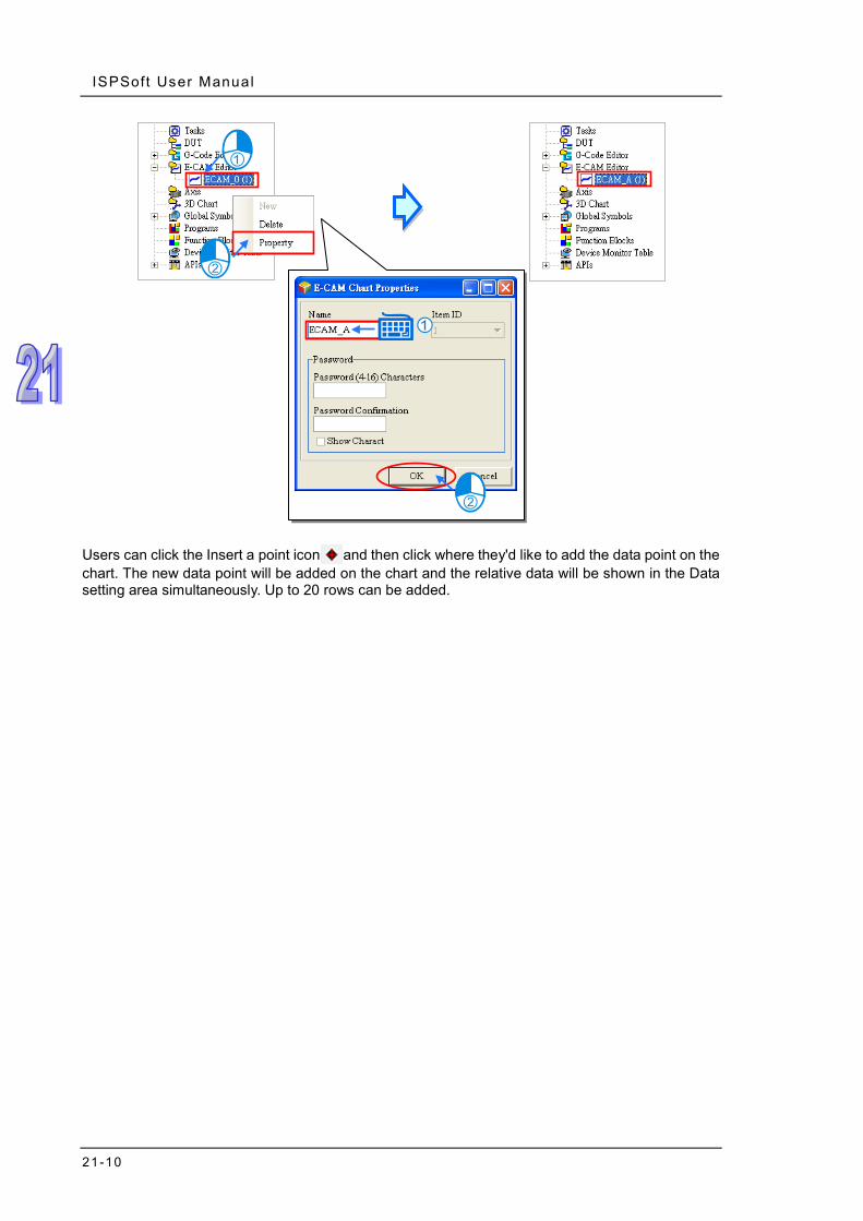
ISPSoft User Manual
21-10
Users can click the Insert a point icon and then click where they'd like to add the data point on the chart. The new data point will be added on the chart and the relative data will be shown in the Data setting area simultaneously. Up to 20 rows can be added.

Chapter 21 G-Code Edi tor and E-CAM Editor
21-11
Users can also click the insert a section icon and then click where they'd like to add the section on the chart. The new section will be added on the chart and the relative data will be shown in the Data setting area simultaneously.

ISPSoft User Manual
21-12
Users can also click the add a new row icon and then type the positions of master and slave axes in the Data setting area to add new E-CAM data. After that users can see the newly added point on the chart. Users can click the delete a row icon to delete the selected point. The cam chart and the relative data in the Data setting area will be updated simultaneously.

Chapter 21 G-Code Edi tor and E-CAM Editor
21-13
In the Data setting area, each column in the table can be specified to define the parameters of the data points which are listed in rows. The whole E-CAM curve are constructed by these data points (max. 20 rows), and the E-CAM cycle will operate according to the designed E-CAM curves. The columns in the Data setting area are explained as below. Master position: the master position of the data point Slave position: the slave position of the data point Slave velocity: the slave velocity calculated automatically according to the specified position. Slave acceleration: the slave acceleration calculated automatically according to the specified
position Cam curve: the cam curve type between the data points, including Const Speed, Const Acc.,
Single Hypot., Cycloid and B-Spline

ISPSoft User Manual
21-14
Resolution: the resolution of current section. The resolution setting should be specified according to the equipment requirements. The equipment operates smoother with a higher resolution; however the E-CAM data size also grows bigger with higher resolution.
Click the Setting icon to open the setting window for the current E-CAM chart.
Master position: defines the display range of the master axis in the E-CAM curve area.
Slave position: defines the display range of the slave axis in the E-CAM curve area.
Resolution: defines the resolution of this E-CAM chart (max.: 2047) After the E-CAM editing is completed, you can use CamTable of MC_CamIn to specify the Name or the Item ID of the E-CAM chart. Also Slave of DFB_CamIn2 can be used to specify the Name or the Item ID of the E-CAM chart. The specified E-CAM chart will be applied in the E-CAM operation when the two instructions are enabled or executed. For detailed explanations of the two instructions, refer to AH Motion – Motion Control Instructions Manual.
After all the setups are done, download the parameters and the project to the PLC. Refer to section 16.1.2 for Downloading / Uploading a Project.
E-CAM Item

22-1
Chapter 22 Wizard Tool
Table of Contents 22.1 Position Planning Table.............................................................................22-2
22.1.1 About the Position Planning Table ...................................................22-2 22.1.2 Setting the Position Planning Table ..................................................22-2 22.1.3 Position Planning Table Simulating ..................................................22-7 22.1.4 Uploading and Downloading Position Planning Table ......................22-9 22.1.5 Control Mode - Single-axis Point-to-Point Motion ...........................22-10 22.1.6 Control Mode - Single-axis Multi-segment Motion .......................... 22-11 22.1.7 Control Mode - 2-axis Linear Interpolation Motion ..........................22-12 22.1.8 Control Mode - 2-axis Arc Interpolation Motion ..............................22-12
22.2 Data Tracer .............................................................................................22-13 22.2.1 About Data Tracer ..........................................................................22-13 22.2.2 Opening the Data Tracer Window ..................................................22-14 22.2.3 Setting Sample Parameters ...........................................................22-16 22.2.4 Sampling Modes.............................................................................22-20 22.2.5 Display Config and Measurement ..................................................22-21
22.3 Data Logger ............................................................................................22-24 22.3.1 About Data Logger .........................................................................22-24 22.3.2 Opening the Data Logger Window .................................................22-25 22.3.3 Setting Sample Parameters ...........................................................22-27 22.3.4 Watch and Record ..........................................................................22-29 22.3.5 Display Config and Measurement ..................................................22-31
22.4 High Speed Counter ................................................................................22-34 22.4.1 About High Speed Counter ............................................................22-34 22.4.2 Using High Speed Counter .............................................................22-35
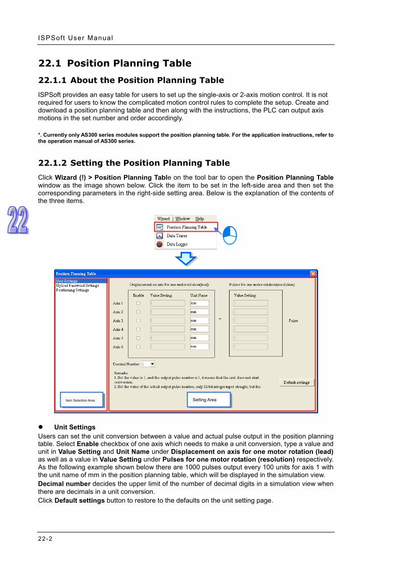
ISPSoft User Manual
22-2
22.1 Position Planning Table
22.1.1 About the Position Planning Table
ISPSoft provides an easy table for users to set up the single-axis or 2-axis motion control. It is not required for users to know the complicated motion control rules to complete the setup. Create and download a position planning table and then along with the instructions, the PLC can output axis motions in the set number and order accordingly. *. Currently only AS300 series modules support the position planning table. For the application instructions, refer to the operation manual of AS300 series.
22.1.2 Setting the Position Planning Table
Click Wizard (!) > Position Planning Table on the tool bar to open the Position Planning Table window as the image shown below. Click the item to be set in the left-side area and then set the corresponding parameters in the right-side setting area. Below is the explanation of the contents of the three items.
Unit Settings Users can set the unit conversion between a value and actual pulse output in the position planning table. Select Enable checkbox of one axis which needs to make a unit conversion, type a value and unit in Value Setting and Unit Name under Displacement on axis for one motor rotation (lead) as well as a value in Value Setting under Pulses for one motor rotation (resolution) respectively. As the following example shown below there are 1000 pulses output every 100 units for axis 1 with the unit name of mm in the position planning table, which will be displayed in the simulation view. Decimal number decides the upper limit of the number of decimal digits in a simulation view when there are decimals in a unit conversion. Click Default settings button to restore to the defaults on the unit setting page.
Setting Area Item Selection Area

Chapter 22 W izard ToolChapter 22 Wizard
22-3
Upload Password Settings The settings are used for protecting the position planning table which has been downloaded to the CPU module from being read by other people. Users can type the same password in Password and Confirmation boxes respectively so as to complete the password setting. To cancel the password protection, type the password in Password box once again and click OK. Select Show Charact checkbox to show the typed character so as to make sure of the correctness of the password input. After the password settings are downloaded to the CPU module, a window will appear asking users to type the correct password whenever an upload of the position planning table is needed. Please note that the upload password only protects the position planning table in the CPU module from being read by other people. To download a new position planning table to the CPU module where there has already been one position planning table, a new position planning table will overwrite the existing one whether there is an upload password set for the existing position planning table in the CPU module or not.
Set a Password
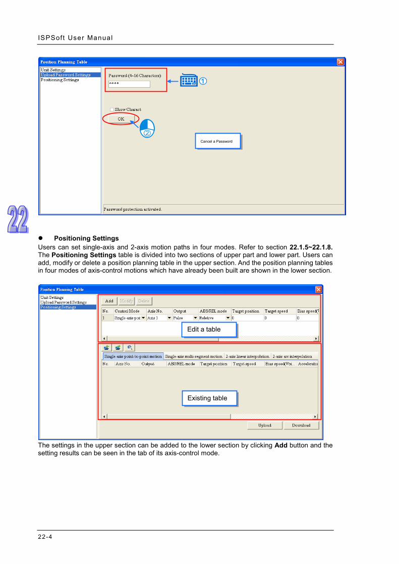
ISPSoft User Manual
22-4
Positioning Settings Users can set single-axis and 2-axis motion paths in four modes. Refer to section 22.1.5~22.1.8. The Positioning Settings table is divided into two sections of upper part and lower part. Users can add, modify or delete a position planning table in the upper section. And the position planning tables in four modes of axis-control motions which have already been built are shown in the lower section.
The settings in the upper section can be added to the lower section by clicking Add button and the setting results can be seen in the tab of its axis-control mode.
Cancel a Password
Existing table
Edit a table

Chapter 22 W izard ToolChapter 22 Wizard
22-5
To modify the already built position planning table, select the right axis-control motion tab and click the table to be modified. The table to be modified will appear in the upper section. Click Modify button after the settings in the table are modified in the upper section. And then the settings will be updated in the lower section.

ISPSoft User Manual
22-6
To delete the already built position planning table, select the right axis-control motion tab and click the table to be deleted. The table to be deleted will appear in the upper section. And then by clicking Delete button, the position planning table will be deleted in the lower section. The position planning table also supports the functions of file exporting and importing so that the already built position planning tables can be used for different projects. Click Export button to open the Export File window. Click Save button to export the position planning table after the path and folder where the table is saved are specified in the Export File window. Click Import button to open the Import File window. Select the file to be imported in the Import File window and then click Open button to import the position planning table.
Export Import

Chapter 22 W izard ToolChapter 22 Wizard
22-7
22.1.3 Position Planning Table Simulating
After a position planning table is set, the path for the table is shown through a graphic simulation. Click any row of the table which is to be simulated and then click Single Axis Simulating Mode or Pair Axis Simulating Mode button. And then the simulation window will show a continuous simulation view of all set paths as below.
For the 2-axis linear interpolation and 2-axis arc interpolation, in the mixture of two motion modes, the continuous path is shown in the same simulation view such as that in the above window including the linear interpolation and arc interpolation. For the single-axis point-to-point motion and single-axis multi-segment motion, only the path of the same motion mode can be shown in the simulation view. The following is the simulation view of the single-axis point to point motion.

ISPSoft User Manual
22-8
The position planning table also supports the simulation starting from a row of the position table in one single mode. First, users should select the row of the table as the start position for the simulation. After the button Simulator by Selecting Item is clicked, the simulation window will display a simulation view starting from the selected row of the table until the end. In the following window, the drawn path starts from row N0. 17, which is part of the linear interpolation in the previous simulation view.
The simulation toolbar is explained as below.
Figure Function
Ticking the checkbox means to show all axes in the simulation view; If not ticking the checkbox, users can select one axis on the drop-down menu, which will be shown in the simulation view.
Users select one number and use thick lines to represent the lines of the number in the graph. The color of lines can be changed by selecting a color block in the right side of the figure.

Chapter 22 W izard ToolChapter 22 Wizard
22-9
Figure Function
Selecting or deselecting the checkbox determines whether to show the arrow representing the motion direction.
Auto fit
The graph is enlarged in X direction.
The graph is narrowed in X direction.
The graph is enlarged in Y direction.
The graph is narrowed in Y direction.
The graph is enlarged.
The graph is narrowed.
22.1.4 Uploading and Downloading Position Planning Table
Users can click Download button on the Position Settings page in the Position Planning Table window to download the table to the CPU module after the table planning is finished and the CPU and computer make a connection as described in section 2.4. Users can click Upload button on the Position Settings page in the Position Planning Table window to read the table in the CPU module. If there is a password set for the position planning table, the password enquiry window will appear and when Upload button is clicked and the position planning table can not be read until the correct password is typed.
The uploading and downloading actions are integrated into the PC=>PLC (Download) window. Users can click Upload or Download of PLC Program Transfer of PLC CPU on the toolbar. Or users can directly click Upload or Download button on the icon toolbar. The following window will appear and the Position Plan Table checkbox can be selected there. The uploading or downloading of the position planning table will be carried out after Transfer button is clicked as below. For the uploading and downloading of a project, refer to section 16.1.

ISPSoft User Manual
22-10
22.1.5 Control Mode - Single-axis Point-to-Point Motion
Users can set the point-to-point positioning control of an axis in this mode.
No.:The row number which is created in order automatically by the software. Maximum
number: 200. Control Mode: Users can select one motion type. Here is Single-axis point-to-point motion
selected. Axis No.: Users can select the axis which is controlled by the position planning table. Output: The method to output pulses, including Pulse, Pulse/Dir and AB phase. ABS/REL mode: Selecting Relative mode means to perform the position control based on the
coordinate which varies with the present coordinate position; Selecting Absolute mode means to perform the position control toward the target position based on the absolute coordinate position.
Target position: Users type a target coordinate. Target speed:Users type a target speed. Bias speed: The speed when the positioning starts and ends. Acceleration time: The time when the target speed is reached. Deceleration time: The time when the stop speed is reached. Completion action: Selecting Go to next segment means to move to the execution of the
next row of the table after the present table execution is completed. Selecting Completion means to end the action after the present table execution is completed.
Completion flag (I/M): The register is set to ON when the present table execution is completed. And I number or the name of M register can be typed only when Completion in Completion action box is selected. For the interrupt numbers supported, refer to the application manual. The ten I numbers:I510~I519 are supported.
No. of next segment: Users can type the number of the next segment of position planning table. N/A means completion. The setting will be automatically effective after Completion in Completion action box is selected. The No. of next segment is not restricted to the same axis number. But please note that the same axis number could not have more than two table numbers or position output instructions which are outputted together.
Notes on the table settings 1. The target speed cannot be set to 0. The target position also cannot be set to 0 in the relative
mode.

Chapter 22 W izard ToolChapter 22 Wizard
22-11
2. I number can be used more than once. Users must determine through which row number the I number can be completely outputted.
3. The instruction which the start table outputs is API2718 TPO. API2719 TPWS can be used to modify the output parameters while PLC is running.
22.1.6 Control Mode - Single-axis Multi-segment Motion
In this mode, users can control the positioning of one axis and make every-segment motion followed by the next-segment motion at the target speed. Or abort the segment and to perform the next-segment motion.
No.: The row number created in order automatically. Maximum number: 200. Control Mode: Users can select one motion type. Here is Single-axis multi-segment motion. Axis No.: Users can select the axis which is controlled by the position planning table. Output: The method to output pulses, including Pulse, Pulse/Dir and AB phase. ABS/REL mode: Selecting Relative mode means to move based on the coordinate which
varies with the present coordinate position; Selecting Absolute mode means to move toward the target position based on the absolute coordinate position.
Target position: Users type a target coordinate. Target speed: Users type a target speed. Interval ACC time: For every segment of output, the interval time for dividing the time during
which current speed changes to target speed into multiple segments. That is the smallest time unit of acceleration. The smoothness of the acceleration rate depends on Interval ACC time and Interval Speed.
Interval Speed: When the current speed changes to the target speed for every segment of output, users can set the speed added during every segment of Interval ACC time. In other words, the speed will be added or reduced by a constant interval speed after every segment of Interval ACC time so as to control the smoothness of the acceleration rate.
Abort signal (I/M): The next segment of position planning table will be performed if the register of interrupt signals is set to ON before the current table is completed. And I number or the name of M register can be typed. For the interrupt numbers supported, refer to the application manual.
Completion action: Selecting Go to next segment means to move to the execution of the next row of the table after the current table execution is completed. Selecting Completion means to end the action after the current table execution is completed.
Completion flag (I/M): The register is set to ON when the table execution is completed. And I number or the name of M register can be typed only when Completion in Completion action box is selected. The ten I numbers:I510~I519 are supported.
No. of next segment: Users can type the number of the next segment of position planning table. N/A means completion. The setting will be automatically effective after Completion in Completion action box is selected. The No. of next segment is not restricted to the same axis number. But please note that the same axis number could not have more than two table numbers or position output instructions which are outputted together.
Notes on the table settings 1. The interval speed and the interval ACC time cannot be set to 0 when the target speed is set to
0. The target position cannot be set to 0 in the relative mode. The target positions of two adjacent row numbers cannot be set to the same value in the absolute mode.
2. I number can be used more than once. Users must determine through which row number the I number can be completely outputted.
3. The instruction which the start table outputs is API2718 TPO. API2719 TPWS can be used to modify the output parameters while PLC is running.

ISPSoft User Manual
22-12
22.1.7 Control Mode - 2-axis Linear Interpolation Motion
Users can set the linear interpolation motion of two axes on the XY plane. Two rows of the position planning table are occupied by using the mode every time.
No.: It is the row number which is automatically created in order in the input area. Two rows of
the table are occupied in the two-axis motion mode. T is attached to the left side of the second row number. Thus the maximum number: 199 and T199 and 100 groups in total for the two-axis mode in the whole table.
Control Mode: Users can select one motion type. Here is 2-axis linear interpolation motion. Coord.: The axes which X and Y axes coordinate stand for in the simulation view. Axis No.: Users can select the axis which is controlled by the position planning table. Output: The method to output pulses, including Pulse, Pulse/Dir and AB phase. ABS/REL mode: Selecting Relative mode means to perform the position control based on the
coordinate which varies with the present coordinate position; Selecting Absolute mode means to perform the position control toward the target position based on the absolute coordinate position.
Target position: Users type a target coordinate. Target speed: Users type a target speed. Acc\Dec time: The time when the target speed is reached and the stop speed is reached Completion action: Selecting Go to next segment means to move to the execution of the
next row of the table after the current table execution is completed. Selecting Completion means to end the action after the table execution is completed.
Completion flag (I/M): The register is set to ON when the table execution is completed. And I number or the name of M register can be typed only when Completion in Completion action box is selected. For the interrupt numbers supported, refer to the application manual. The ten I numbers:I510~I519 are supported.
No. of next segment: Users can type the number of the next segment of position planning table. N/A means completion. The setting will be automatically effective after Completion in Completion action box is selected. The No. of next segment is not restricted to the same axis number. But please note that the same axis number could not have more than two table numbers or position output instructions which are outputted together.
Notes on the table settings 1. The PLC will automatically run at the set speed when the target speed or the Acc\Dec time is set
to 0. The target position cannot be set to 0 in the relative mode. The target positions of two adjacent row numbers cannot be set to the same value in the absolute mode.
2. I number can be used more than once. Users must determine through which row number the I number can be completely outputted.
3. The instruction which the start table outputs is API2718 TPO. API2720 TPWL can be used to modify the output parameters while PLC is running.
22.1.8 Control Mode - 2-axis Arc Interpolation Motion
Users can set the arc interpolation motion of two axes on the XY plane. Two rows of position planning tables are occupied by using the mode every time.
No. : The row number is automatically created orderly in the input area. It will take up two rows
of the table for two-axis motion mode. “T” will be added as a prefix for the number on the second row. In other words, when in the two-axis mode, there will be a total of 100 groups in

Chapter 22 W izard ToolChapter 22 Wizard
22-13
the table and the maximum number will be 199 and T199. Control Mode: Users can select one motion type. Here is 2-axis arc interpolation motion. Coord.: The axes which X and Y axis coordinates stand for in the simulation view. Axis No.: Users can select the axis which is controlled by the position planning table. Output: The method to output pulses, including Pulse, Pulse/Dir and AB phase. ABS/REL mode: Selecting Relative mode means to move based on the coordinate which
varies with the present coordinate position; Selecting Absolute mode means to move toward the target position based on the absolute coordinate.
Target position: Users type a target coordinate. Center shift value: The distance from the center of the line between the arc target point and
start point to the center of a circle, such as S in the following figures. From point A to point B, a clockwise rotation will generate an arc less than 180 ° if S>0 and an arc more than 180 ° if S<0.
Direction: Users can select CW clockwise motion or CCW counter clockwise motion. Completion action: Selecting Go to next segment means to move to the execution of the
next row of the table after the current table execution is completed. Selecting Completion means to end the action after the table execution is completed.
Completion flag (I/M): The register is set to ON when the table execution is completed. And I number or the name of M register can be typed only when Completion in Completion action box is selected. For the interrupt numbers supported, refer to the application manual. The ten I numbers:I510~I519 are supported.
No. of next segment: Users can type the number of the next segment of position planning table. N/A means completion. The setting will be automatically effective after Completion in Completion action box is selected. The No. of next segment is not restricted to the same axis number. But please note that the same axis number could not have more than two table numbers or position output instructions which are outputted together.
Notes on the table settings 1. The PLC automatically calculates the output speed in this function. The target position cannot
be set to 0 in the relative mode. The target positions of two adjacent row numbers cannot be set to the same value in the absolute mode.
2. I number can be used more than once. Users must determine through which row number the I number can be completely outputted.
3. The instruction which the start table outputs is API2718 TPO. API2721 TPWL can be used to modify the output parameters while PLC is running.
22.2 Data Tracer
22.2.1 About Data Tracer
Data Tracer is used for the real-time collection of variable symbols or values or states in devices after some trigger condition is met so as to draw curve charts for analysis of value trends.

ISPSoft User Manual
22-14
*. Currently Data Tracer only supports AS300 series.
22.2.2 Opening the Data Tracer Window Please compile the current project before using the function. Click Wizard > Data Tracer on the tool bar to open the Data Tracer setup window as the image shown below.

Chapter 22 W izard ToolChapter 22 Wizard
22-15
Below is the explanation of the Data Tracer window.
Icon toolbar: Various function buttons are provided for operation of the data tracer. The functions of buttons are explained below.
Wave shape display area: The variable symbols or wave shapes of devices which will be traced are displayed in real time.
Setting and measurement area: There are 3 tabs in total. Sample Parameter tab is used for setting the sample source and trigger condition. Display Config tab is used for modifying the color and proportion of wave shapes. Measurement tab is used for displaying the value which is measured with the measurement tool.
Explanation of icon buttons on the icon toolbar
Icon Name Function
Save All The sample settings and curve data results are saved to the specified path.
Export Sampling
Config The sample settings are exported to the specified path.
Import Sampling
Config The sample settings are imported from the specified path.
Export Curve Data The sample curve data are exported in the format of.bmp and .csv to the specified path.
Configuration The colors of curves in the data tracer and environment can be set.
Separate Curves Multiple curves are separated automatically.
Overlap Curves Multiple curves are overlapped with the center line.

ISPSoft User Manual
22-16
Icon Name Function
Show Grid Line Show or Hide the grid line.
Horizontal
Measuring Lines There will be two horizontal lines in the curve display area for users to measure the curve.
Vertical Measuring
Lines There will be one vertical line in the curve display area for users to measure the curve.
Connect/Disconnect Connect or disconnect the PC and PLC.
Upload Sampling Config from PLC
The sample settings in the data tracer are read from the PLC.
Download Sampling
Config to PLC The sample settings in the data tracer are written to the PLC.
Real Time Monitor The PC reads the curve of the source from the PLC in real time.
One-Shot Trigger After the trigger condition is met, a total 200 points of curve data, including pre- and post- of the triggered point will be read from the PLC.
Continuous Trigger Whenever the trigger condition is met, a total 200 points of curve data, including pre- and post- of the triggered point will be read from the PLC.
22.2.3 Setting Sample Parameters
The sample source area will appear at the bottom of the window by clicking Sample Parameter tab. Sample source is classified into Bit type and Word type. Data type can be variable symbols or devices of Timer or Counter, which can be added to the sample sources of Bit and Word. Click the button of Symbol Name to open the Add Sample Source window. Then click the button of Symbol Name in the Add Sample Source window and select the variable symbol name to be added in the Choose Symbol window or directly type a device name in the Device Name box. And the data will be added to the sample source list after Add button is clicked.

Chapter 22 W izard ToolChapter 22 Wizard
22-17
The source of a variable symbol only comes from the global symbol table in ISPSoft. If there are device addresses and identifier comments which are set by manual, they will be added to the sample source list as well.

ISPSoft User Manual
22-18
To delete the sample source which has been added, click the record to be deleted and then click Delete.
Sample period setting area is used for setting the cycle time of sampling of every sample point in the data tracer. Selecting System Cycle Time means that sampling is carried out once every one scan cycle of the PLC. Customized Time indicates sampling is done once every a period of time set.
Trigger condition setting area is used for setting the trigger position and condition. The PLC will store and read 200 pieces of sample data and display the data in the data tracer if the trigger condition is met.
The trigger position settings are different for the one-shot trigger and continuous trigger. Refer to section 22.2.4 for more information. Click the button of Symbol/Device to open the Choose Symbol window and select a symbol as the trigger condition. But the symbol/ device here must be among those which have already been added to the sample source list. Users can directly type a symbol or device in the Symbol /Device box as well.

Chapter 22 W izard ToolChapter 22 Wizard
22-19
The Condition area is used for setting the trigger condition of sampling. Bit under Condition will be selected automatically if the bit-type variable symbol or device is selected in the Symbol /Device box. Users can select ON, OFF, Rising edge trigger, Falling edge trigger or Rising or Falling edge trigger on the drop-down menu. The trigger will be displayed in the data tracer if the set symbol or device meets the set condition.
Word under Condition will be selected automatically if the word-type variable symbol or device is selected in the Symbol /Device box. Users can select >, <, =, != ( not equal), ~ (a range) or !~ (out of a range) in the drop-down menu and type values in the boxes to the left and right. The trigger will be displayed in the data tracer if the set symbol or device meets the set condition. In the following figure, the value in D100, which is between 10~100 meets the trigger condition. But if the set value is 10 !~ 100, the value in D100 should be less than 10 or more than 100 so as to meet the trigger condition.
Click on the icon toolbar after sample parameters have been set so as to go into the online connection. Then click to download the settings to the CPU module. Please note that the set parameter settings will be cleared after the CPU is powered off. Thus the settings should be re-downloaded after power on again. Click the export button to save the sample parameter settings in the PC for the future import of the settings with the import button .
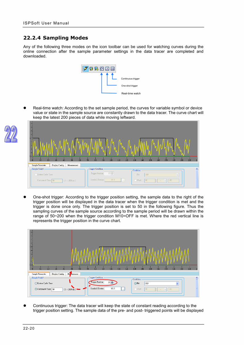
ISPSoft User Manual
22-20
22.2.4 Sampling Modes
Any of the following three modes on the icon toolbar can be used for watching curves during the online connection after the sample parameter settings in the data tracer are completed and downloaded.
Real-time watch: According to the set sample period, the curves for variable symbol or device
value or state in the sample source are constantly drawn to the data tracer. The curve chart will keep the latest 200 pieces of data while moving leftward.
One-shot trigger: According to the trigger position setting, the sample data to the right of the
trigger position will be displayed in the data tracer when the trigger condition is met and the trigger is done once only. The trigger position is set to 50 in the following figure. Thus the sampling curves of the sample source according to the sample period will be drawn within the range of 50~200 when the trigger condition M10=OFF is met. Where the red vertical line is represents the trigger position in the curve chart.
Continuous trigger: The data tracer will keep the state of constant reading according to the
trigger position setting. The sample data of the pre- and post- triggered points will be displayed
Continuous trigger
One-shot trigger
Real-time watch

Chapter 22 W izard ToolChapter 22 Wizard
22-21
in the data tracer whenever the trigger condition is met. To view the curve chart, the state of the continuous trigger button must be restored from OFF to ON. As the following example shows the trigger position is set to 50 and thus the curves for the sample source according to the sample period setting will be drawn 200 pieces including 49 pieces of the pre-triggered points and 150 pieces of the post-triggered points whenever the trigger condition M10=OFF is met. Where the red vertical line is represents the trigger position in the wave shape chart.
22.2.5 Display Config and Measurement
The curve shape can be adjusted to a better display effect in the data tracer on the Display Config tab in whatever mode. X Axis Proportion is used for modifying the number of points per div of the horizontal coordinate.
The color, proportion and shift of every curve can be set as well. Proportion refers to the proportion of the vertical coordinate. The proportions are respectively set to 200/Div and 100/Div as the value per div for comparison in the following figures.

ISPSoft User Manual
22-22
Shift can be set to modify the position of the curve in the display as shown in the following figures.

Chapter 22 W izard ToolChapter 22 Wizard
22-23
The curve values in the data tracer can be measured by using horizontal and vertical measuring lines after the Measurement tab is clicked. Click to open the horizontal measuring line and to open the vertical measuring line.
Drag two horizontal measuring lines Y1 and Y2 to the position where the measurement is performed. The values of the horizontal measuring line will display at the bottom of the following figure. After the coordinate of Y axis is selected in the box, the value of the horizontal measuring line Y1 will display in Y1 box and the value of the horizontal measuring line Y2 will display in Y2 box. The value in I∆Y box is the difference value between Y1 and Y2. The values in Mean, Max and Min boxes are the mean, maximum and minimum values which are automatically figured out for the sample curve. They have nothing to do with the horizontal measuring line.
Shift: 0
Shift: 5

ISPSoft User Manual
22-24
Y Value column will display Y value at the crossing of Xc and various sample sources by dragging the vertical measuring line Xc as below.
22.3 Data Logger
22.3.1 About Data Logger
Data logger is used for the long-term recording of variable symbols or values or states in devices, drawing curve charts and storing them in the PLC and the memory card of the PLC for analysis of value trends. *. Currently Data Logger only supports AS300 series.

Chapter 22 W izard ToolChapter 22 Wizard
22-25
22.3.2 Opening the Data Logger Window
Please compile the current project before using the function. And then click Wizard> Data Logger to open the Data Logger window as below.
Below is the explanation of the Data Logger window.

ISPSoft User Manual
22-26
Icon toolbar: Various function buttons are provided for operation of the data logger. The functions of buttons are explained below.
Wave shape display area: The variable symbols or wave shapes of devices which will be recorded are displayed in real time.
Setting and measurement area: There are 3 tabs in total. Sample Parameter tab is used for setting the sample source and trigger condition. Display Config tab is used for modifying the color and proportion of wave shapes. Measurement tab is used for displaying the value which is measured with the measurement tool.
Explanation of icon buttons on the icon toolbar
Icon Name Function
Save All The sample settings and curve data result are saved to the specified path.
Export Sampling
Config The sample settings are exported to the specified path.
Import Sampling
Config The sample settings are imported from the specified path.
Export Curve Data The sample curve data are exported in the format of.bmp and .csv to the specified path.
Configuration The colors of curves in the data tracer and environment are set.
Separate Curves Multiple curves are separated automatically.
Overlap Curves Multiple curves are overlapped with the center line.
Show Grid Line Show or Hide grids
Horizontal
Measuring Lines There will be two horizontal lines in the curve display area for users to measure the curve.
Vertical Measuring
Lines There will be one vertical line in the curve display area for users to measure the curve.
Connect/Disconnect The PC and PLC are connected or disconnected.
Upload Sampling Config from PLC
The sample settings in the data tracer are read from the PLC.
Download Sampling
Config to PLC The sample settings in the data tracer are written to the PLC.
Real Time Monitor The PC reads the curve of the source from the PLC in real time.
Record Data Click this button to start recording or cancel the clicking of the button to stop recording.
Upload Sampling Config from PLC
The recorded data in the data logger are read from the PLC.
Write to Memory
Card Write the data recorded in the PLC to the memory card.

Chapter 22 W izard ToolChapter 22 Wizard
22-27
22.3.3 Setting Sample Parameters
The sample source area will appear at the bottom of the window by clicking Sample Parameter tab. Sample source is classified into Bit type and Word type. Data type can be variable symbols or devices of Timer or Counter, which can be added to the sample sources of Bit and Word. Click the button of Symbol Name to open the Add Sample Source window. Then click the button of Symbol Name in the Add Sample Source window and select the variable symbol name to be added in the Choose Symbol window or directly type a device name in the Device Name box. And the data will be added to the sample source list after Add button is clicked.

ISPSoft User Manual
22-28
The source of a variable symbol only comes from the global symbol table in ISPSoft. If there are device addresses and identifier comments which are set by manual, they will be added to the sample source list as well.
To delete the sample source which has been added, click the record to be deleted and then click Delete.
Parameters area is used for setting the sample parameters related with the data logger. The Sample Points box is to set the sampling times in every sample source. The Sample Period box is for setting the period of sampling in the data logger. The right-side setting area is used for selecting Stop Recording or Continue Recording (Replace the old data) when the data logger has recorded the number of the set sample points.
Click on the icon toolbar after sample parameters have been set to go into the online connection. Then click to download the settings to the CPU module. Click the export button to save the sample parameter settings in the PC for the future import of the settings with the import button .

Chapter 22 W izard ToolChapter 22 Wizard
22-29
22.3.4 Watch and Record
The buttons on the icon toolbar can be used to execute the Real-time Watch or Record Data action in the mode of online connection after the sample parameter setting in the data logger and downloading are completed.
Real-time Watch: According to the set sample period, the curves for the variable symbol or
device value or state of the sample source are constantly drawn to the data logger. The screen will be adjusted to the appropriate range based on the curve shape and only the data of the latest sample points are kept. The PLC does not record the sample source in this mode.
Record Data: The button can be used to make the PLC record the variable symbols of sample
sources or the values or states in devices and the data are stored in the memory card of the PLC. Click Record Data button on the toolbar to start recording. A window will appear to notify once the recording is finished and if Stop Recording is selected under Action When Sample Points Reach in Sample Parameter setting area, the system will ask whether to upload the recorded data after reaching the set sample points. After uploading is finished, another window will prompt asking whether to continue recording data. After continuing recording data is cancelled, the curves for recorded data will be updated to the data logger. During the recording of the sample points, if the Record Data button is restored to the state of not being pressed, the recording will be stopped immediately. At this moment, users can click the Upload Sampling Config from PLC button to update the curves for recorded data to the data logger.
Record Data
Real-time Watch

ISPSoft User Manual
22-30
The PLC will constantly record the sample source data and keep several pieces of latest sample point data if Continue Recording (Replace the old data) is selected under Action When Sample Points Reach in the Sample Parameter setting area. First the Record Data button is restored to the state of not being pressed. And then the Upload Sampling Config from PLC button is clicked to update the curves for the data recorded by the PLC to the data logger.
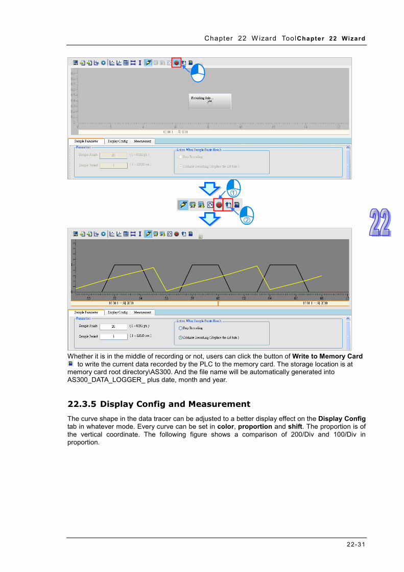
Chapter 22 W izard ToolChapter 22 Wizard
22-31
Whether it is in the middle of recording or not, users can click the button of Write to Memory Card
to write the current data recorded by the PLC to the memory card. The storage location is at memory card root directory\AS300. And the file name will be automatically generated into AS300_DATA_LOGGER_ plus date, month and year.
22.3.5 Display Config and Measurement
The curve shape in the data tracer can be adjusted to a better display effect on the Display Config tab in whatever mode. Every curve can be set in color, proportion and shift. The proportion is of the vertical coordinate. The following figure shows a comparison of 200/Div and 100/Div in proportion.

ISPSoft User Manual
22-32
Shift is used for adjusting the position of the curve in the screen as below.

Chapter 22 W izard ToolChapter 22 Wizard
22-33
The curve values in the data logger can be measured by using horizontal and vertical measuring lines after the Measurement tab is clicked. Click to open the horizontal measuring line and to open the vertical measuring line.
Drag two horizontal measuring lines Y1 and Y2 to the position where the measurement is performed. The values of the horizontal measuring line will display at the bottom of the following figure. After the coordinate of Y axis is selected in the box, the value of the horizontal measuring line Y1 will display in Y1 box and the value of the horizontal measuring line Y2 will display in Y2 box. The value in I∆Y box is the difference value between Y1 and Y2. The values in Mean, Max and Min boxes are the mean, maximum and minimum values which are automatically figured out for the sample curve. They have nothing to do with the horizontal measuring lines.
Shift: 0
Shift: 5

ISPSoft User Manual
22-34
Y Value column will display Y value at the crossing of Xc and various sample sources by dragging the vertical measuring line Xc as below.
22.4 High Speed Counter
22.4.1 About High Speed Counter
The high speed counter tool enables users to select the register number of the corresponding high speed counter based on the type of the high speed counter, format of the value to be counted and input point number so that DCNT instruction can be set quickly. *. Currently the high speed counter only supports the LD language for AS300 series modules.

Chapter 22 W izard ToolChapter 22 Wizard
22-35
22.4.2 Using High Speed Counter
Double-click DCNT instruction in the ladder diagram to open the High Speed Counter Setting window as follows.
Firstly, select the type of the high speed counter such as Hardware-1 Phase 1 Input, Hardware 1 Phase 2 Input and so on. Then select the input point or counter from the drop-down menu based on the actual need and the contents in the right-side fields will be changed accordingly.
Afterwards, set the value to be counted by selecting Decimal, Hex or D register from the drop-down menu and inputting the value or D register number in the right-side field.
Click OK button after the setting above is done. And the high speed counter number and setting values will be updated in the inputs of DCNT instruction.

ISPSoft User Manual
22-36
MEMO

A-1
Appendix A USB Connection Table of Contents A.1 Installing the USB Driver for a PLC ....................................................... A-2 A.2 Creating a Driver Whose Connection Type is USB in COMMGR ............ A-5 A.3 Setting the USB Port on a DVP-SX2 Series PLC ................................... A-7

ISPSof t User Manual
A-2
A.1 Installing the USB Driver for a PLC The installation of the USB driver for a PLC on Windows XP is introduced below. If users want to install the USB driver for a PLC on another operating system, they have to refer to the instructions in the operating system for more information about the installation of new hardware. (1) Make sure that the PLC is supplied with power normally. Connect the PLC to a USB port on
the computer with a USB cable. Select the No, not this time option button in the Found New Hardware Wizard window, and then click Next.
(2) The name of the USB device detected is displayed in the window. The device name shown in the figure below is the name of an AH500 series CPU module. Different models have different names. Please select the Install from a lost or specific location (Advanced) option button.
(3) The Delta PLCs which are equipped with built-in USB interfaces are listed in the tabled below. After ISPSoft version 2.00 or above is installed, the drivers for DVP-SX2 series PLCs, DVP-SE series PLCs, and AH500 series CPU modules will be in the folders denoted by the paths in the table.
Model Path DVP-SX2 Installation path of ISPSoft\drivers\SX2_USB_Driver\ DVP-SE Installation path of ISPSoft\drivers\Delta_PLC_USB_Driver\ AH500 Installation path of ISPSoft\drivers\Delta_PLC_USB_Driver\
*. The default installation path of ISPSoft is C:\Program Files\Delta Industrial Automation\ISPSoftx.xx.

Appendix A 0BUSB Connec ti on
A-3
Specify a path according to the PLC which is connected. If the driver for a PLC is gotten in another way, users have to specify the corresponding path. Click Next to carry on the installation.

ISPSof t User Manual
A-4
(4) After the correct driver is found in the folder denoted by the path, the system will install the driver. If the Hardware Installation window appears during the installation, please click Continue Anyway.
(5) Click Finish after the installation is finished.

Appendix A 0BUSB Connec ti on
A-5
(6) Open the Device Manager window after the installation is finished. If the name of the USB device connected is under Ports (COM&LPT), the installation of the driver is successful. The operating system assigns a communication port number to the USB device.
*. The device name shown in the figure above is the name of an AH500 series CPU module. Different models have different names.
Additional remark If the PLC is connected to another USB port on the computer, the system may ask users to install
the driver again. The users can follow the steps above, and install the driver again. After the driver is installed, the communication port number that the operating system assigns to the USB device may be different.
If Windows XP SP3 has not been installed on the computer, an error message will appear during the installation. Users can deal with the problem in either way below. (a) Cancel the installation, install Windows XP SP3, and reinstall the driver according to the steps
above. (b) Get the file needed, and specify the path pointing to the file in the Files Needed window.
A.2 Creating a Driver Whose Connection Type is USB in COMMGR
The steps of creating a driver whose connection type is USB in COMMGR are as follows. (1) Make sure that the PLC is supplied with power normally. Connect the PLC to a USB port on
the computer with a USB cable. (2) Make sure that COMMGR is started, and the icon representing COMMGR is displayed on the
system tray. If the icon representing COMMGR is not displayed on the system tray, users can start COMMGR by clicking the shortcut on the Start menu (Start>Programs>Delta Industrial Automation>Communication>COMMGR).

ISPSof t User Manual
A-6
(3) Double-click the icon representing COMMGR on the system tray, and then click Add in the COMMGR window.
(4) Type a driver name in the Driver Name box, and then select USB (Virtual COM) in the Type
drop-down list box in the Connection Setup section. If the PLC connected is a DVP-SX2 series PLC, RS232 in the Type drop-down list box must be selected. Please refer to the following section for more information.
(5) Select a device name which corresponds to the PLC connected in the COM Port drop-down
list box in the Communication Port section, select the number of times the sending of a command is retried if a connection error occurs in the Time of Auto-retry box, and select an interval of retrying the sending of a command in the Time Interval of Auto-retry box. Click OK.

Appendix A 0BUSB Connec ti on
A-7
If the device name corresponding to the PLC connected does not appear in the COM Port drop-down list box, users have to check whether the device name of the PLC connected is under Ports (COM&LPT). If the device name of the PLC connected is not under Ports (COM&LPT), the users have to check whether the PLC is correctly connected to the computer with the USB cable, and check whether the driver for the PLC is corrected installed on the computer. After the users make the checks, they have to close the Driver Properties window, and open the window again.
(6) Click the driver created in the COMMGR window, and then click Start.
*. Please refer to section 2.4 for more information about subsequent tests and the operation of COMMFR.
A.3 Setting the USB Port on a DVP-SX2 Series PLC The operation of the USB port on a DVP-SX2 series PLC differs from the operation of the USB ports on other models in that a circuit which converts USB to RS-232 is installed in the DVP-SX2 series PLC. As a result, the operation inside the DVP-SX2 series PLC adopts RS-232 although the port on the PLC is a USB port. Users must select RS232 in the Type drop-down list box in the Driver Properties window if they want to create a driver in COMMGR. The setting of the communication protocol for exchanging data through the USB port is the same as the setting of the communication protocol for exchanging data through a general RS-232 port. Users can set the communication protocol for exchanging data through the USB port on a DVP-SX2 PLC by means of writing a value into D1109. Please refer to the programming manual for DVP-SX2 series PLCs for more information. If users want to create the driver in COMMGR, they have to make sure that the communication protocol for exchanging data through the driver is the same as the communication protocol for exchanging data through the USB port on a DVP-SX2.
MEMO

ISPSof t User Manual
A-8

B-1
Appendix B Important Points Related to CPU Modules
Table of Contents B.1 Device Addresses in AH/AS Series CPU Modules ................................. B-2
B.1.1 Devices in AH/AS series CPU Modules .......................................... B-2 B.1.2 Manipulating the Bits in the X/Y/D/L Devices .................................. B-3 B.1.3 Updating Input/Output Directly ....................................................... B-4
B.2 Device Resources in AH/AS Series CPU Modules ................................. B-5 B.2.1 AHCPU500-EN/AHCPU500-RS2 ................................................... B-5 B.2.2 AHCPU510-EN/AHCPU510-RS2 ................................................... B-6 B.2.3 AHCPU520-EN/AHCPU520-RS2 ................................................... B-6 B.2.4 AHCPU530-EN/AHCPU530-RS2 ................................................... B-6 B.2.5 AHCPU511-EN/AHCPU511-RS2 ................................................... B-7 B.2.6 AHCPU521-EN ............................................................................ B-7 B.2.7 AHCPU531-EN ............................................................................ B-8 B.2.8 AHxxEMC .................................................................................... B-8 B.2.9 AS300 ......................................................................................... B-9
B.2 Data Exchange Setups ........................................................................ B-9 B.3 Program Compilation and Time for Uploading/Downing ....................... B-10

ISPSof t User Manual
B -2
AH/AS series PLCs are slightly different from DVP series PLCs. Users have to read the manuals for different models before they develop projects. The points to which users have to pay attention when they develop a project for an AH/AS series CPU module are described in appendix B.
B.1 Device Addresses in AH/AS Series CPU Modules
B.1.1 Devices in AH/AS series CPU Modules
The devices in AH/AS series CPU modules are listed in the following table. Device type Access property Description
X Bit/Word Input relay It represents the state of a digital input. (*1)
Y Bit/Word Output relay It represents the state of a digital output. (*1)
M Bit Auxiliary relay The state of a bit is stored in an auxiliary relay.
S Bit Stepping relay It is used as a state flag for a step in a sequential function chart.
D Bit/Word Data register Operation data is stored in a data register. (*1)
L Bit/Word Link register A link register is used for data exchange. (*1) (*2)
T
Bit
Timer If a timer is used as a bit device, the timer is ON when the time interval which is measured conforms to the setting value, and the timer is OFF when the time interval which is measured does not conform to the setting value.
Word Timer If a timer is used as a word device, the value stored in the timer is the present value of the timer.
C
Bit
Counter If a counter is used as a bit device, the counter is ON when the number of times a particular event or process has occurred conforms to the setting value, and the counter is OFF when the number of times a particular event or process has occurred does not conform to the setting value.
Word Counter If a counter is used as a word device, the value stored in the counter is the present value of the counter.
HC
Bit
32-bit counter If a 32-bit counter is used as a bit device, the 32-bit counter is ON when the number of times a particular event or process has occurred conforms to the setting value, and the 32-bit counter is OFF when the number of times a particular event or process has occurred does not conform to the setting value.
Word
32-bit counter If a 32-bit counter is used as a word device, the value stored in the 32-bit counter is the present value of the 32-bit counter.

Appendix B 0BImpor tant Points Related to CPU Modules
B -3
Device type Access property Description
E Word Index register The value stored in an index register indicates the offset for a device modified. (*3)
SM Bit Special auxiliary relay It is used as a state flag for a special function of the
system. (*4)
SR Word Special data register It is used as a data register for a special function of the
system. (*4) *1. AH/AS series CPU modules support the manipulation of the bits in the input relays, the output relays, the data
registers, and the link registers. For example, X0.1 indicates that bit 1 in X0 is manipulated, Y0.1 indicates that bit 1 in Y0 is manipulates, D0.1 indicates that bit 1 in D0 is manipulates, and L0.1 indicates that bit 1 in L0 is manipulated. Please refer to the following sections for more information.
*2. A link register is used for data exchange, but it can also be used as a general data register. There is no link register for AS series PLC.
*3. The index registers that AH/AS series CPU modules have are E devices. AH500 series CPU modules do not have F devices.
*4. AH/AS series PLCs are different from DVP series PLCs in that the special auxiliary relays and the special data registers in AH500 series PLCs are called SM devices and SR devices.
Please refer to Programming Manual or PLC Instructions and Special Registers Reference in a project for a CPU module in ISPSoft for more information.
B.1.2 Manipulating the Bits in the X/Y/D/L Devices
The X/Y devices in DVP series PLCs are represented by X0, Y1, and etc. The X/Y devices which are used as bit devices in AH/AS series CPU modules are represented by X0.0, Y0.0, and etc. Besides, the X/Y devices which are used as word devices in AH/AS series CPU modules are represented by X0, Y0, and etc. X0.0 represents the first bit (the lowest bit) in X0, and X0.15 represents the last bit (the highest bit) in X0.
After the value in D0 is moved to Y1, the states of Y1.0~Y1.15 will change.

ISPSof t User Manual
B -4
The bits in the X/Y devices in AH/AS series CPU modules can be manipulated. The bits in the D/L devices in AH500 series CPU modules can also be manipulated in the same way. Please refer to the following example. The state of M0 is sent to D0.2. Suppose the initial value in D0 is 0. When M0 is ON, the value in D0 becomes 4.
If the bits in the X/Y/D/L devices which are word devices in an AH500 series CPU module are manipulated, the memory blocks that the X/Y/D/L devices occupy are manipulated. However, the memory blocks that the T/C/HC devices used as bit devices occupy are different from the memory blocks that the T/C/HC devices used as word devices occupy. If a timer is used as a bit device, the timer is ON when the time interval which is measured conforms to the setting value, and the timer is OFF when the time interval which is measured does not conform to the setting value. If a timer is used as a word device, the value stored in the timer is the present value of the timer. If a counter is used as a bit device, the counter is ON when the number of times a particular event or process has occurred conforms to the setting value, and the counter is OFF when the number of times a particular event or process has occurred does not conform to the setting value. If a counter is used as a word device, the value stored in the counter is the present value of the counter.
B.1.3 Updating Input/Output Directly
The way in which the input/output in an AH/AS series CPU module is updated is similar to the way in which the input/output in a DVP series PLC is updated in that the input/output in either model will be updated after the program in the model is scanned. However, an AH/AS series CPU module supports a special modification. If the X device or the Y device in the network in a program is modified by “D”, the system updates the state of the device when the network is executed. Only X devices and Y devices can be modified by “D”. Symbols can not be modified by “D”. When network 1 is executed, the system reads the state of X0.0. Likewise, the system sends the state of M1 to Y0.0 when network 2 is executed.
The instructions which support the modification by “D” are listed in the following table. If an X device which is modified by “D” or a Y device which is modified by “D” is used in an instruction which is not listed in the table below, the system will regard it as incorrect syntax, and an error will occur after the

Appendix B 0BImpor tant Points Related to CPU Modules
B -5
program is compiled. Besides, only the bits in the X devices which are word devices and the bits in the Y devices which are word devices can be modified by “D”, and the operands in the applied instructions can not be modified by “D”.
Device type Instruction X LD/LDI/LDP/LDF/OR/ORI/ORP/ORF/AND/ANI/ANDP/ANDF Y OUT/SET/RST/PLS/PLF
The figure below is an example of applying the modification by “D” legally.
The figure below is an example of applying the modification by “D” illegally. The Y device is modified by “D”. It can not be used as an input contact.
B.2 Device Resources in AH/AS Series CPU Modules
B.2.1 AHCPU500-EN/AHCPU500-RS2
Device type Address range X Word: X0~X63 Bit: X0.0~X63.15 Y Word: Y0~Y63 Bit: Y0.0~Y63.15 D Word: D0~D16383 Bit: D0.0~D16383.15 L Word: L0~L16383 Bit: L0.0~L16383.15 M M0~M8191 S S0~S2047 C C0~C2047
HC HC0~HC63 T T0~T2047 E E0~E31
SR SR0~SR2047 SM SM0~SM2047
Number of memory blocks which can be assigned to function block instances
64

ISPSof t User Manual
B -6
B.2.2 AHCPU510-EN/AHCPU510-RS2
Device type Address range X Word: X0~X127 Bit: X0.0~X127.15 Y Word: Y0~Y127 Bit: Y0.0~Y127.15 D Word: D0~D32767 Bit: D0.0~D32767.15 L Word: L0~L32767 Bit: L0.0~L32767.15 M M0~M8191 S S0~S2047 C C0~C2047
HC HC0~HC63 T T0~T2047 E E0~E31
SR SR0~SR2047 SM SM0~SM2047
Number of memory blocks which can be assigned to function block instances
256
B.2.3 AHCPU520-EN/AHCPU520-RS2
Device type Address range X Word: X0~X255 Bit: X0.0~X255.15 Y Word: Y0~Y255 Bit: Y0.0~Y255.15 D Word: D0~D65535 Bit: D0.0~D65535.15 L Word: L0~L65535 Bit: L0.0~L65535.15 M M0~M8191 S S0~S2047 C C0~C2047
HC HC0~HC63 T T0~T2047 E E0~E31
SR SR0~SR2047 SM SM0~SM2047
Number of memory blocks which can be assigned to function block instances
512
B.2.4 AHCPU530-EN/AHCPU530-RS2
Device type Address range X Word: X0~X511 Bit: X0.0~X511.15 Y Word: Y0~Y511 Bit: Y0.0~Y511.15 D Word: D0~D65535 Bit: D0.0~D65535.15 L Word: L0~L65535 Bit: L0.0~L65535.15 M M0~M8191 S S0~S2047 C C0~C2047
HC HC0~HC63

Appendix B 0BImpor tant Points Related to CPU Modules
B -7
Device type Address range T T0~T2047 E E0~E31
SR SR0~SR2047 SM SM0~SM2047
Number of memory blocks which can be assigned to function block instances
1024
B.2.5 AHCPU511-EN/AHCPU511-RS2
Device type Address range
X Word: X0~X255 Bit: X0.0~X255.15
Y Word: Y0~Y255 Bit: Y0.0~Y255.15
D Word: D0~D49151 Bit: D0.0~D49151.15
L Word: L0~L49151 Bit: L0.0~L49151.15
M M0~M8191
S S0~S2047
C C0~C2047
HC HC0~HC63
T T0~T2047
E E0~E31
SR SR0~SR2047 (AHCPU511-EN) SM0~SM4095 (AHCPU511-RS2)
SM SM0~SM2047 (AHCPU511-EN) SM0~SM4095 (AHCPU511-RS2)
B.2.6 AHCPU521-EN
Device type Address range
X Word: X0~X511 Bit: X0.0~X511.15
Y Word: Y0~Y511 Bit: Y0.0~Y511.15
D Word: D0~D98303 Bit: D0.0~D98303.15
L Word: L0~L98303 Bit: L0.0~L98303.15
M M0~M8191
S S0~S2047
C C0~C2047
HC HC0~HC63
T T0~T2047

ISPSof t User Manual
B -8
E E0~E31
SR SR0~SR2047
SM SM0~SM2047
B.2.7 AHCPU531-EN
Device type Address range
X Word: X0~X1023 Bit: X0.0~X1023.15
Y Word: Y0~Y1023 Bit: Y0.0~Y1023.15
D Word: D0~D131071 Bit: D0.0~D131071.15
L Word: L0~L131071 Bit: L0.0~L131071.15
M M0~M8191
S S0~S2047
C C0~C2047
HC HC0~HC63
T T0~T2047
E E0~E31
SR SR0~SR2047
SM SM0~SM2047
B.2.8 AHxxEMC
Device type Address range
X Word: X0~X511 Bit: X0.0~X511.15
Y Word: Y0~Y511 Bit: Y0.0~Y511.15
D Word: D0~D65535 Bit: D0.0~D65535.15
L Word: L0~L65535 Bit: L0.0~L65535.15
M M0~M8191
S S0~S2047
C C0~C2047
HC HC0~HC63
T T0~T2047
E E0~E31
SR SR0~SR2047
SM SM0~SM2047
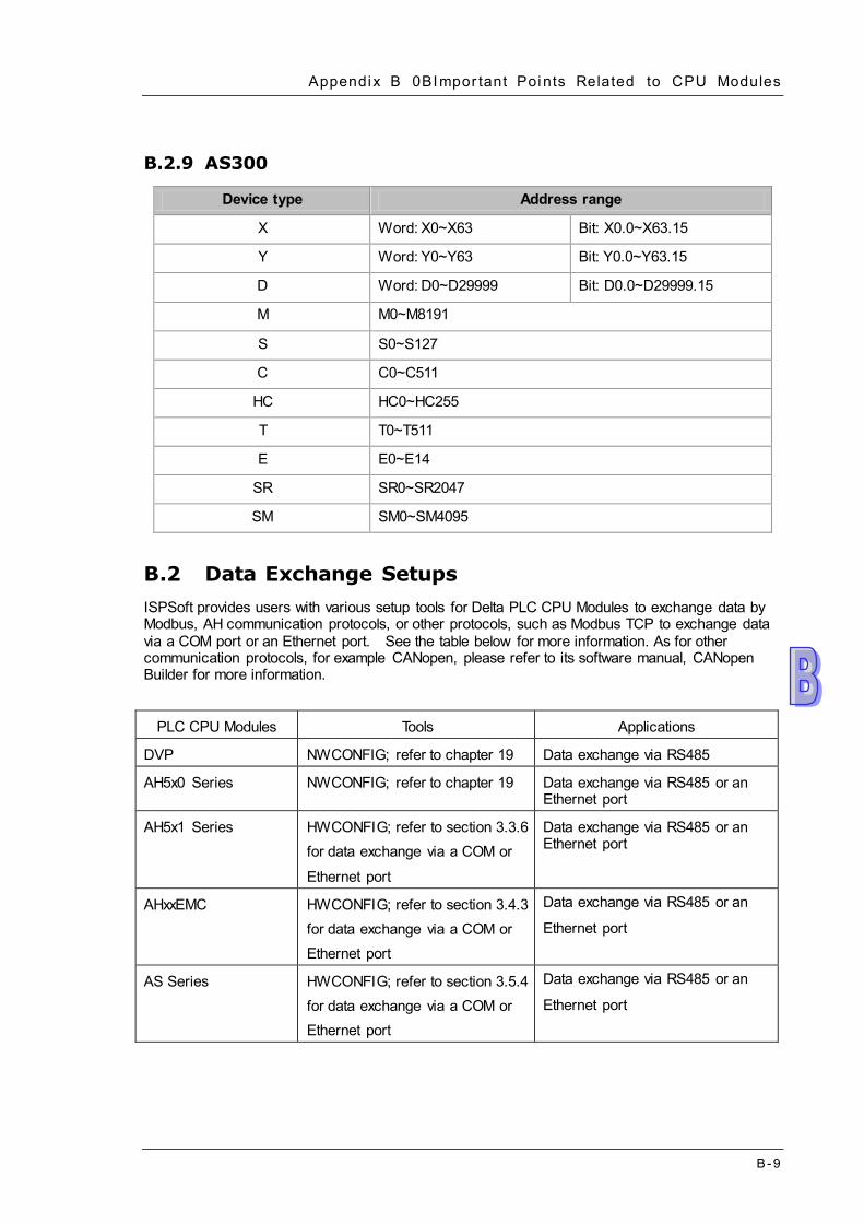
Appendix B 0BImpor tant Points Related to CPU Modules
B -9
B.2.9 AS300
Device type Address range
X Word: X0~X63 Bit: X0.0~X63.15
Y Word: Y0~Y63 Bit: Y0.0~Y63.15
D Word: D0~D29999 Bit: D0.0~D29999.15
M M0~M8191
S S0~S127
C C0~C511
HC HC0~HC255
T T0~T511
E E0~E14
SR SR0~SR2047
SM SM0~SM4095
B.2 Data Exchange Setups ISPSoft provides users with various setup tools for Delta PLC CPU Modules to exchange data by Modbus, AH communication protocols, or other protocols, such as Modbus TCP to exchange data via a COM port or an Ethernet port. See the table below for more information. As for other communication protocols, for example CANopen, please refer to its software manual, CANopen Builder for more information.
PLC CPU Modules Tools Applications
DVP NWCONFIG; refer to chapter 19 Data exchange via RS485
AH5x0 Series NWCONFIG; refer to chapter 19 Data exchange via RS485 or an Ethernet port
AH5x1 Series HWCONFIG; refer to section 3.3.6 for data exchange via a COM or
Ethernet port
Data exchange via RS485 or an Ethernet port
AHxxEMC HWCONFIG; refer to section 3.4.3 for data exchange via a COM or Ethernet port
Data exchange via RS485 or an
Ethernet port
AS Series HWCONFIG; refer to section 3.5.4 for data exchange via a COM or Ethernet port
Data exchange via RS485 or an
Ethernet port

ISPSof t User Manual
B -10
B.3 Program Compilation and Time for Uploading/Downing The duration for ISPSoft to compile programs is involved with the size, quantity of the programs and the variable symbols and the condition of the computer. The duration to upload/download is involved with the size of the project, the connection type and the communication speed. The following information is listed for reference. Operation System on the computer: CPU Intel(R) I7, RAM 4GB, Windows 7 32-bit
Project contents: 2 variable symbols and a basic ladder diagram with a total of 5000 networks; each network contains 1 contact and 1 output coil. Program compilation time: about 2 seconds Time for uploading: via a USB port, about 4.9 seconds Time for downloading: via a USB port, about 4.6 seconds

C-1
Appendix C Print Management Tool Table of Contents C.1 Introduction of the Environment ................................................................ C-2 C.2 Introduction of the Setting Area ................................................................ C-3

ISPSoft User Manual
C-2
C.1 Introduction of the Environment The print management tool provides a convenient operation interface. Users can set a print format, and preview the document which will be printed in the Print Preview window.
Print button: After the setting is complete, users can click the Print button to start the printing of the document.
Setting area: There are two tabs in the setting area. One is the View Settings tab, and the other is the Print Settings tab.
Preview area: The document which will be printed is displayed in this area.
If users move the mouse cursor to the preview area and click the left mouse button, the pointer will become a magnifying glass. After the left mouse button is clicked, ISPSoft will zoom in on the preview area. After the right mouse button is clicked, ISPSoft will zoom out on the preview area.

Appendix C Pr int Management Tool
C-3
C.2 Introduction of the Setting Area After users click the View Settings tab, they can adjust the display state of the preview area.
If the print area does not fit the printed page, the system will divide the print area into
several pages. After One Page is clicked, one page will be displayed. After Overview is clicked, all the pages will be displayed. The number of pages into which the print area is divided is under the Overview button.
Users can select a page which will be displayed by clicking Page Up or Page Down. The present page number and the total number of pages are under the buttons.
The graphic representations show the relative positions of all the pages. The red block represents the present page.
One page
Overview

ISPSoft User Manual
C-4
After users click the Print Setting tab, they can set the print format.
After Paper Settings is clicked, the Print Setup window will appear. Users can scale the document by selecting a percentage in the Print Ratio box. The
users can also insert page numbers and a page title in the document. User can set document margins they want.
After the setting is complete, users can click the Print button to start the printing of the document.