ispe labs.pdf
176
This Document is licensed to Mr. George Francis Dublin 17, ID number: 53416 Downloaded on: 4/2/13 4:13 AM
Transcript of ispe labs.pdf
This Document is licensed to
Mr. George FrancisDublin 17,
ID number: 53416
Downloaded on: 4/2/13 4:13 AM
This Document is licensed to
Mr. George FrancisDublin 17,
ID number: 53416
Downloaded on: 4/2/13 4:13 AM
GE imagination at work
GE Power & WaterWater & Process TechnologiesAnalytical Instruments
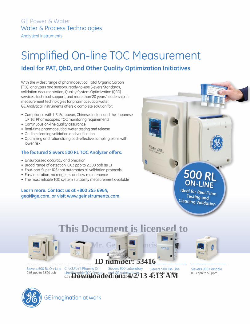
Simplified On-line TOC Measurement Ideal for PAT, QbD, and Other Quality Optimization Initiatives
With the widest range of pharmaceutical Total Organic Carbon (TOC) analyzers and sensors, ready-to-use Sievers Standards, validation documentation, Quality System Optimization (QSO) services, technical support, and more than 20 years’ leadership in measurement technologies for pharmaceutical water, GE Analytical Instruments offers a complete solution for:
• Compliance with US, European, Chinese, Indian, and the Japanese (JP 16) Pharmacopeia TOC monitoring requirements
• Continuous on-line quality assurance• Real-time pharmaceutical water testing and release• On-line cleaning validation and verification• Optimizing and rationalizing cost-effective sampling plans with
lower risk
The featured Sievers 500 RL TOC Analyzer offers:
• Unsurpassed accuracy and precision• Broad range of detection (0.03 ppb to 2,500 ppb as C)• Four-port Super iOS that automates all validation protocols• Easy operation, no reagents, and low maintenance• The most reliable TOC system suitability measurement available
Learn more. Contact us at +800 255 6964, [email protected], or visit www.geinstruments.com.
CheckPoint Pharma On-Line/Portable TOC Sensor0.21 ppb to 1,000 ppb
Sievers 500 RL On-Line0.03 ppb to 2,500 ppb
Sievers 900 Laboratory and GE Autosampler0.03 ppb to 50 ppm
Sievers 900 On-Line0.03 ppb to 50 ppm
Sievers 900 Portable0.03 ppb to 50 ppm
500 RL ON-LINEIdeal for Real-Time Testing and Cleaning Validation
ISPE Quality Lab Facilities Ad - June 2012.indd 1 5/30/2012 10:11:04 AM
This Document is licensed to
Mr. George FrancisDublin 17,
ID number: 53416
Downloaded on: 4/2/13 4:13 AM
Quality Laboratory Facilities
Disclaimer: This Guide describes how to apply a risk assessment to a quality laboratory facility and identify issues to be
considered. The purpose of the quality laboratory is to support the execution of testing that assures the manufactured products meet the identity, strength, purity, efficacy, and safety as specified in an approved regulatory file. ISPE cannot ensure and does not warrant that a system managed in accordance with this Guide will be acceptable to regulatory authorities. Further, this Guide does not replace the need for hiring professional engineers or technicians.
Limitation of Liability InnoeventshallISPEoranyofitsaffiliates,ortheofficers,directors,employees,members,oragentsofeach
ofthem,ortheauthors,beliableforanydamagesofanykind,includingwithoutlimitationanyspecial,incidental,indirect,orconsequentialdamages,whetherornotadvisedofthepossibilityofsuchdamages,andonanytheoryofliabilitywhatsoever,arisingoutoforinconnectionwiththeuseofthisinformation.
© Copyright ISPE 2012. All rights reserved.
No part of this document may be reproduced or copied in any form or by any means – graphic, electronic, or mechanical, including photocopying, taping, or information storage and retrieval systems – without written permission of ISPE.
All trademarks used are acknowledged.
ISBN 978-1-936379-43-9
For individual use only. © Copyright ISPE 2012. All rights reserved.
This Document is licensed to
Mr. George FrancisDublin 17,
ID number: 53416
Downloaded on: 4/2/13 4:13 AM
Page 2 ISPE Good Practice Guide: Quality Laboratory Facilities
Preface The ISPE Good Practice Guide: Quality Laboratories Facilities aims to provide a baseline for the design of
pharmaceutical quality laboratories supporting GxP regulated facilities producing pharmaceutical products. This Guide is intended to assist in the development of criteria for determining system impact and component criticality for a quality laboratory. It considers critical early planning decisions and questions, such as through-puts and the consequences of location. Guidance is provided on how to apply a risk assessment to a quality laboratory facility and identify issues to be considered.
Special Dedication to Tom Creaven
This Guide is dedicated to the memory of Tom Creaven, who was responsible for the Architectural Chapter until his passing at which time William Ferguson assumed the responsibility.
Tom Creaven’s career spanned more than 25 years at Schering Plough and he was a Director of Global Engineering Services. He served as one of the company representatives to ISPE and was the main contact person for Schering Plough’s Global Engineering Team. Tom was involved in a significant number of the projects for Schering Plough and had responsibility for the construction of laboratory facilities, office buildings, and manufacturing facilities. One of his last projects for the firm was the construction of a new cGMP Clinical Research Manufacturing Facility in Summit, N.J. This project was very successful and involved the use of modular construction to expedite the delivery of the facility. Tom was heavily involved in the remediation of the manufacturing site in Kenilworth to comply with the consent decree requirements. This led to the construction of new tablet manufacturing facility that at the time was state of the art when it was completed.
Tom was a licensed Professional Engineer in the state of N.J. and was an active member of ISPE for more than 20 years. He was a mentor to countless young engineers and a consummate professional who ensured that the firm paid attention to detail. Tom was an advocate for the ISPE Baseline Guides and promoted their use as a tool for engineering. Tom’s legacy lives on today in the scores of junior colleagues that benefited from his training and guidance over the years, in addition to the friendships that he made with ISPE members, contractors, engineers, and other professionals. He is sorely missed by all.
For individual use only. © Copyright ISPE 2012. All rights reserved.

This Document is licensed to
Mr. George FrancisDublin 17,
ID number: 53416
Downloaded on: 4/2/13 4:13 AM
ISPE Good Practice Guide: Page 3Quality Laboratory Facilities
Acknowledgements Chapter Writers and Reviewers
The following individuals took lead roles in the preparation of this document. The company affiliations are as of the final draft of the Guide.
James M. O’Brien (Chair) NAMA Industries, Inc. USA Euan D. Smith (Co-Chair) MSD United Kingdom
Mark A. Butler IPS USA Mary Ellen Craft Fluor USA Thomas J. Creaven Schering-Plough Corp. USA Cesar B. Daou, PE Daou Engineers Inc. USA Donna A. DeFreitas Vanderweil Engineers USA James J. Dolceamore AstraZeneca Pharmaceuticals LP USA Dr. William E. Ferguson Ferguson Consulting LLC USA Frederick L. Fricke, PhD FDA USA Peter B. Gardner Torcon Inc. USA Michelle M. Gonzalez BioPharm Engineering Consultant USA Gerard J. Guillorn M+W Shanghai Co., Ltd. USA Terry A. Jacobs, AIA Jacobs/Wyper Architects, LLP USA Kaushik S. Master Amgen Inc. USA Catherine E. Middelberg Pfizer USA Kimberly D. Snyder Proteus USA Dr. Gregory L. Tewalt Samsung Biologics South Korea
Many other individuals provided topics and comments prior to, and during, the writing of this Guide; although they are too numerous to list here, their input is greatly appreciated.
Coverphoto:courtesyofChiesiFarmaceuticiS.p.A.,www.chiesigroup.com.
For individual use only. © Copyright ISPE 2012. All rights reserved.
This Document is licensed to
Mr. George FrancisDublin 17,
ID number: 53416
Downloaded on: 4/2/13 4:13 AM
ISPE Headquarters600 N. Westshore Blvd., Suite 900, Tampa, Florida 33609 USA
Tel: +1-813-960-2105, Fax: +1-813-264-2816
ISPE Asia Pacific Office73 Bukit Timah Road, #04-01 Rex House, Singapore 229832
Tel: +65-6496-5502, Fax: +65-6336-6449
ISPE China OfficeSuite 2302, Wise Logic International Center
No. 66 North Shan Xi Road, Shanghai, China 200041 Tel +86-21-5116-0265, Fax +86-21-5116-0260
ISPE European OfficeAvenue de Tervueren, 300, B-1150 Brussels, Belgium
Tel: +32-2-743-4422, Fax: +32-2-743-1550
www.ISPE.org
For individual use only. © Copyright ISPE 2012. All rights reserved.
This Document is licensed to
Mr. George FrancisDublin 17,
ID number: 53416
Downloaded on: 4/2/13 4:13 AM
ISPE Good Practice Guide: Page 5Quality Laboratory Facilities
Table of Contents 1 Background and Purpose .................................................................................................. 7 1.1 Background ..................................................................................................................................................7 1.2 Purpose ........................................................................................................................................................8 1.3 Objectives ....................................................................................................................................................8 1.4 Scope of This Guide ....................................................................................................................................9 1.5 Issues Which Define the Design of Quality Laboratories ............................................................................. 9
2 Concepts and Regulatory Philosophy .............................................................................11 2.1 Introduction ................................................................................................................................................ 11 2.2 Facility, Equipment, and Personnel ............................................................................................................ 11
2.3 GMP Requirements ...................................................................................................................................16 2.4 General Laboratory and Support Space Characterizations ....................................................................... 17 2.5 Speciality Laboratories...............................................................................................................................23 2.6 Specialty Compound Laboratories .............................................................................................................27 3 Laboratory Process and Equipment ............................................................................... 31 3.1 Introduction ................................................................................................................................................31 3.2 Areas Supporting General Laboratory Processes and Procedures ........................................................... 31 3.3 Functional Area Equipment Allocation .......................................................................................................32
4 Hazard and Safety ............................................................................................................. 37 4.1 Introduction ................................................................................................................................................37 4.2 Occupational Exposure Limits ...................................................................................................................37
5 Risk Assessment .............................................................................................................. 45 5.1 Introduction ................................................................................................................................................45 5.2 Regulatory Review .....................................................................................................................................46 5.3 Assessing Risk ...........................................................................................................................................46
6 The Project Execution ...................................................................................................... 49 6.1 The Laboratory Design Process ................................................................................................................49 6.2 The Project Team .......................................................................................................................................52 6.3 The Basis of Design ...................................................................................................................................54 6.4 Design Development..................................................................................................................................58 6.5 Construction ...............................................................................................................................................58 6.6 Commissioning and Qualification...............................................................................................................59 6.7 Budgeting ...................................................................................................................................................59 6.8 Cost Control During Construction ..............................................................................................................62 7 Architectural ...................................................................................................................... 69 7.1 Introduction ................................................................................................................................................69 7.2 Laboratory Design and Organization .........................................................................................................70 7.3 Architectural Finishes .................................................................................................................................81 7.4 Laboratory Design Check List ....................................................................................................................82 7.5 Organization of Quality Laboratory Spaces ...............................................................................................84
For individual use only. © Copyright ISPE 2012. All rights reserved.
This Document is licensed to
Mr. George FrancisDublin 17,
ID number: 53416
Downloaded on: 4/2/13 4:13 AM
Page 6 ISPE Good Practice Guide: Quality Laboratory Facilities
8 HVAC .................................................................................................................................. 87 8.1 Introduction ................................................................................................................................................ 87 8.2 User Requirements .................................................................................................................................... 89 8.3 HVAC Design Parameters ......................................................................................................................... 93
9 Electrical .......................................................................................................................... 107 9.1 Introduction .............................................................................................................................................. 107 9.2 General Requirements ............................................................................................................................. 107 9.3 Power Distribution .................................................................................................................................... 107 9.4 AreaClassification ................................................................................................................................... 107 9.5 Lighting .................................................................................................................................................... 108 9.6 Grounding ................................................................................................................................................ 108 9.7 Telephones, Paging, and Radio Systems ................................................................................................ 109 9.8 Laboratory Information Management System .......................................................................................... 109 9.9 Wiring Methods ........................................................................................................................................ 110 10 Laboratory Site Utility and Support Systems................................................................111 10.1 Introduction ...............................................................................................................................................111 10.2 Laboratory Water ......................................................................................................................................111 10.3 Additional Programming Considerations.................................................................................................. 136 10.4 Utility and Support Spaces....................................................................................................................... 139
11 CommissioningandQualification ................................................................................. 141 11.1 Introduction .............................................................................................................................................. 141 11.2 Scope ....................................................................................................................................................... 142 11.3 DevelopingaCommissioningandQualificationStrategy ........................................................................ 143 11.4 Commissioning as Good Engineering Practice (GEP)............................................................................. 145 11.5 Qualification ............................................................................................................................................. 147
12 Appendix 1 – European Considerations ....................................................................... 149 12.1 Introduction .............................................................................................................................................. 150 12.2 The Differences ........................................................................................................................................ 150
12.3 European Association Contact Details ..................................................................................................... 152
13 Appendix 2 – References ............................................................................................... 155 13.1 Further Reading ....................................................................................................................................... 158
14 Appendix 3 – Glossary ................................................................................................... 159 14.1 Acronyms and Abbreviations ................................................................................................................... 160 14.2 Definitions ................................................................................................................................................ 163
For individual use only. © Copyright ISPE 2012. All rights reserved.
This Document is licensed to
Mr. George FrancisDublin 17,
ID number: 53416
Downloaded on: 4/2/13 4:13 AM
ISPE Good Practice Guide: Page 7Quality Laboratory Facilities
1 Background and Purpose1.1 Background
Quality laboratories execute testing protocols to establish the stability baseline of materials and products, for initial material release, for in-process verifications, for final product release, and to investigate product complaints. The quality laboratory scientists develop and execute tests to guarantee the quality, integrity, and stability of pharmaceutical and animal care products and their components at each stage of a manufacturing process. Their analytical methods are defined in Standard Operating Procedures (SOPs). These methods are used to assure compliance to design and performance specifications prior to release of products to the market.
The quality control function is to verify the quality of the product and its components at each stage of manufacturing through a variety of diagnostic methods. The quality laboratory facility supports the scientists in executing these tests. The tests being performed verify that materials and products meet the necessary criteria to allow for the approval of materials at receiving, the movement of in-process materials from operation to operation and the final release for distribution. The quality laboratory is responsible for testing and release for both in house and outsourced manufacturing, packaging, and distribution. In addition, the quality laboratory supports the testing necessary for stability studies as well as clinical trial manufacturing, packaging, and distribution.
Quality operations are typically responsible for ongoing facility and utility monitoring. In addition, the Quality Control Department supports the commissioning and validation of new facilities in preparation for their release for use.
The application of this Guides’ recommendations to a particular laboratory operation should be based on a risk assessment of the testing platforms being applied and the activities being performed. It should not be considered as a universal and generic code applied to all situations. The laboratory under consideration should be defined in concert with the laboratory management documenting their requirements and special needs. The design development team then participates in a joint venture risk assessment performed in concert with their scientific client to reach agreement on the characteristics of the facility to meet the agreed upon risk.
Quality control laboratories can be quite simplistic. Package testing laboratories can be an open room with no special considerations other then security of the samples being tested and verified. In-process control may be performed in rooms close to the physical operation. On the other hand, product testing may require, no to high levels of isolation, depending on the test being performed and the potency of the product being tested. Microbiology laboratories require levels of storage and isolation to protect the samples being tested and the individuals performing the tests. Microbiology laboratories have levels of isolation and safety equipment, including biological safety cabinets and a variety of enclosure containers, to provide containment of aerosols generated by many microbiological procedures. Different levels of isolation are provided depending on the biological compounds hazard level. The three elements of containment include laboratory practice and technique, safety equipment, and facility design.
The most important element to safety of the scientist is adherence to standard practices and techniques. Persons working with agents and materials must be aware of the potential hazards and must be trained and proficient in practices and techniques necessary for safely handling of such materials. The director or person in charge of the laboratory is responsible for providing and arranging for appropriate training of personnel and developing of the approved SOPs documenting these techniques and practices.
Each laboratory should develop an operations manual that identifies the hazards that will or may be encountered, and that specifies practices and procedures followed to minimize or eliminate exposures to these hazards. Personnel should be advised of special hazards and should be obliged to read and follow the necessary practices and procedures. A scientist, trained and knowledgeable in appropriate laboratory techniques, safety procedures, and hazards associated with handling the agents and materials to be tested must be responsible for the conduct of work with any agents or materials.
For individual use only. © Copyright ISPE 2012. All rights reserved.
This Document is licensed to
Mr. George FrancisDublin 17,
ID number: 53416
Downloaded on: 4/2/13 4:13 AM
Page 8 ISPE Good Practice Guide: Quality Laboratory Facilities
When standard laboratory practices are not sufficient, additional measures may be needed. The scientist or group trained and knowledgeable in appropriate laboratory techniques, safety procedures, and hazards associated with handling the agents and materials to be tested must be involved in the facility design and engineered features and safety equipment. In addition, it would be a best practice to have this team involved in the risk assessment process to be assured all are in agreement with the final facilities and safety equipment to be employed in the delivered laboratory. The design of the laboratory contributes to the laboratory workers’ protection, provides a barrier to protect persons outside the laboratory, and protects persons in the community from agents that may be accidentally released.
1.2 Purpose
The purpose of the quality laboratory is to support the execution of testing that assures the manufactured products meet the identity, strength, purity, efficacy, and safety as specified in an approved regulatory file. It is important to note that a quality laboratory verifies product quality and does not affect product quality. When a quality test fails, i.e., the product fails to meet specifications, the material is quarantined, rejected, or subjected to further test procedures or rework.
The design of the quality laboratory should minimize or eliminate the risk of the facility contributing risk to patient safety through test function failure to detect an Out of Specification (OOS) product. This type of failure may be derived from laboratory conditions or because of a support system malfunction.
Regulatory initiatives and guidelines emphasize the principles of managing risk and the application of these techniques to pharmaceutical facility inspections and submission review. For a quality laboratory and its associated utilities and support systems, a documented risk assessment can identify those areas or systems having an impact on product quality and quality control functions, and provide a rationale for commissioning, verification, and qualification decisions.
1.3 Objectives
This Guide aims to assist project teams in the development of criteria for determining system impact and component criticality for a quality laboratory project. Using these requirements and design documentation, a review of the intended purpose of a laboratory area or the type of testing to be performed in a laboratory area may identify potential risks inherent in the design. Guidance is provided on how to apply a risk assessment to a quality laboratory facility and identify issues to be considered. Managing risk allows a consistent and science-based approach to decision making, across the life cycle of a product or project.
This Guide presents design guidelines focused on pharmaceutical quality laboratories within or part of a GxP regulated environment. Quality laboratories range across various functions, testing platforms, and product types.
This Guide aims to:
• Provide a baseline for the design of pharmaceutical quality laboratories supporting GxP regulated facilities producing pharmaceutical products for human and animal applications
• Assist in the interpretations of function, operation, or design for quality laboratories within the GxP regulatory environment
• Encourage and guide consistency in the baseline design and performance of quality laboratories
• Help to reduce costs in producing pharmaceutical products for human applications1
1 May also apply to animal applications.
For individual use only. © Copyright ISPE 2012. All rights reserved.
This Document is licensed to
Mr. George FrancisDublin 17,
ID number: 53416
Downloaded on: 4/2/13 4:13 AM
ISPE Good Practice Guide: Page 9Quality Laboratory Facilities
1.4 Scope of This Guide
This Guide considers:
• Critical early planning decisions and questions, such as through-puts, as determinants of size and capacity, and the consequences of location, e.g., adjacent to or remote from manufacturing, centralized, or decentralized locations
• Identification and characterization of laboratories and support spaces
• The role of regulation via the GxPs and CFR 21 Part 11 [1]
• The parallel and controlling role of prevailing building codes and building regulations
• Prevailing critical industry and association standards related to systems and subsystems
• Systems necessary to support quality laboratory operations
• Various disciplines (e.g., architectural/HVAC/plumbing and fire protection/electrical), design philosophy, design approach, and appropriate alternatives
• Subsystems such as security, monitoring and instrumentation, and IT and electronic data capture
• Construction costs and their control
This Guide supports and references other ISPE Guidance Documents and provides associated examples. The relevant ISPE Guidance Documents should be consulted for regulatory expectations in a specific topic area.
1.5 IssuesWhichDefinetheDesignofQualityLaboratories
Maintaining Good Laboratory Practice (GLP) is a prerequisite of an effective and efficient operation. This can be accomplished through:
• Security
• Product and people flow
• Environmental control and pressurization
• Monitoring
• IT systems
• Electronic data
• Documentation
• Sample storage and long term retention
Critical aspects for establishing a laboratory environment include:
• The tests being performed and the equipment to support those tests
For individual use only. © Copyright ISPE 2012. All rights reserved.

This Document is licensed to
Mr. George FrancisDublin 17,
ID number: 53416
Downloaded on: 4/2/13 4:13 AM
Page 10 ISPE Good Practice Guide: Quality Laboratory Facilities
• Providing the chemicals, solvents, and gases needed to support both the testing and the equipment
• Robust building utility systems, validated where needed, supporting an uninterrupted testing environment
• Flexibility to allow for the evolution of equipment and technology, products, and regulations
For individual use only. © Copyright ISPE 2012. All rights reserved.
This Document is licensed to
Mr. George FrancisDublin 17,
ID number: 53416
Downloaded on: 4/2/13 4:13 AM
ISPE Good Practice Guide: Page 11Quality Laboratory Facilities
2 Concepts and Regulatory Philosophy2.1 Introduction
This Chapter discusses aspects of quality laboratories that should be addressed when developing the Basis of Design (BOD) for sampling, storage, and analytical areas to help reduce risk and maintain the integrity of a sample and the test environment. The health and safety of laboratory personnel and control data are also considered during the BOD.
Meetingsshouldbeheldwithlaboratorypersonneltodefinetherequirementsforusersandsettheparametersfordesign. Laboratory design should consider:
• Physicalandenvironmentneeds,utilities,equipment,andmaterialstosupportthemeasuresandactivitiesintesting a sample
• Thespaceneededtoconductatest,aswellasspacefortheorderlyplacementandstorageofequipmentandmaterials
• Benchesandfloormaterialsthatarecompatiblewiththeirintendeduse,cleanliness,andmaintenance
• Mechanical,electrical,andplumbingneedstodelivertheappropriateairchanges,lightingandpower,alongwithtemperature and humidity control
Once the parameters for design are established, a design review should be performed as a risk assessment to ensure that the design meets regulatory, organizational, and user requirements.
2.2 Facility, Equipment, and Personnel
2.2.1 Facilities
Quality laboratories are intended to support the testing and release of:
• Rawmaterials
• ActivePharmaceuticalIngredients(APIs)
• Inprocessmaterials
• Finishedproduct
Typically, quality laboratories also support stability testing of products. The day to day testing for manufactured products may be separated from ongoing stability testing, depending on an organization’s philosophy.
Quality operations are typically responsible for facility and utility monitoring, and the testing of products along with their release for use. Laboratory operations can extend throughout an entire facility, including obtaining samples at off-site operations such as contract manufacturers, as well as on-site in receiving, manufacturing, packaging, and warehousing operations. Quality laboratories are normally responsible for the approval of the movement of materials from operation to operation. Quality laboratories are considered integral to facilities.
For individual use only. © Copyright ISPE 2012. All rights reserved.
This Document is licensed to
Mr. George FrancisDublin 17,
ID number: 53416
Downloaded on: 4/2/13 4:13 AM
Page 12 ISPE Good Practice Guide: Quality Laboratory Facilities
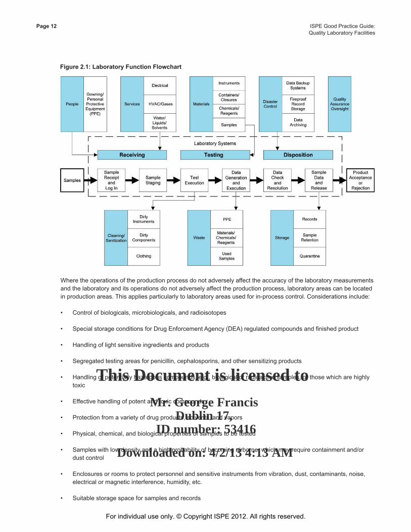
Figure 2.1: Laboratory Function Flowchart
Where the operations of the production process do not adversely affect the accuracy of the laboratory measurements and the laboratory and its operations do not adversely affect the production process, laboratory areas can be located in production areas. This applies particularly to laboratory areas used for in-process control. Considerations include:
• Controlofbiologicals,microbiologicals,andradioisotopes
• SpecialstorageconditionsforDrugEnforcementAgency(DEA)regulatedcompoundsandfinishedproduct
• Handlingoflightsensitiveingredientsandproducts
• Segregatedtestingareasforpenicillin,cephalosporins,andothersensitizingproducts
• Handlingofpotentiallyhazardouscompounds,e.g.,biologicalorradioactivesamples,orthosewhicharehighlytoxic
• Effectivehandlingofpotentandtoxiccompounds
• Protectionfromavarietyofdrugproducts,solvents,andvapors
• Physical,chemical,andbiologicalpropertiesofsamplestobetested
• Sampleswithlowdensityandahighprobabilityofbecomingairborne,whichmayrequirecontainmentand/ordust control
• Enclosuresorroomstoprotectpersonnelandsensitiveinstrumentsfromvibration,dust,contaminants,noise,electrical or magnetic interference, humidity, etc.
• Suitablestoragespaceforsamplesandrecords
For individual use only. © Copyright ISPE 2012. All rights reserved.
This Document is licensed to
Mr. George FrancisDublin 17,
ID number: 53416
Downloaded on: 4/2/13 4:13 AM
ISPE Good Practice Guide: Page 13Quality Laboratory Facilities
• Monitoredenvironmentalconditions
• Securitytocontrolaccesstounauthorizedpersonnel
• Trafficpatternsandfunctionaladjacencies
• Segregatingdirtyandcleanoperationsandmaterials
• Protectionofproduct,personnel,andequipmentfromcontamination
• Temperature,humidity,andairflowrequirementsfor:
- Equipment
- Instrumentation
- Storage materials
- Standards
- Samples
• Layout,design,andconstructionmaterialsforeffectivecleaning
• Sufficientspaceandorganizationtoprovideadequatesegregationandpreventconfusiontoavoidmix-upsandcross contamination
• Sufficientspacetoallowforequipmentcleaning,maintenance,andrepair
• Regulatoryguidanceonsensitives,pesticides,andpoisons
2.2.2 Equipment
The design team and laboratory personnel should focus on documenting instruments and equipment needed tosupportthetestingprogramwiththeappropriateaccuracy,range,andprecisionforaspecifiedtask.Specificconditionsshouldbedefinedtoassureequipmentaccuracyandoperationduringtesting.
Storageneedsshouldbedefinedforin-processsamples.Theflowoftheprocessandpersonnelshouldbedefinedforplacementofequipment.Thedesignteamshouldusethisinformationtodefinethenecessaryutilitiesandappropriate access to the equipment with regard to set up, operation, cleaning, and maintenance.
This process should provide an understanding of:
• Equipmentandinstrumentsneeded
• Specialconditionsdemandedbytheprocess/testingtheequipmentsupports
• Equipmentplacementandprocessandpersonnelflow
• Specialrequirementssuchasclearancefrommovingpartsandenvironmentaldemands
• Theeffectofbuildingvibrationonrobotsandothersensitiveequipment
• Safetyconsiderationforallequipmentincludingroboticequipment
For individual use only. © Copyright ISPE 2012. All rights reserved.
This Document is licensed to
Mr. George FrancisDublin 17,
ID number: 53416
Downloaded on: 4/2/13 4:13 AM
Page 14 ISPE Good Practice Guide: Quality Laboratory Facilities
• Spaceforsamplepreparation
• Spacefordatarecording
• Spaceandequipmentaccessforsetup,calibration,operationandcleaning
• Spaceforequipmentandfacilitymaintenance
2.2.3 Personnel
The design team and the laboratory personnel should document personnel requirements, the number of spaces needed to support the necessary number of analysts, as well as process space and with operational issues, e.g., potency,radioactivity,andpowerbackup.Thisexerciseshoulddefineandclarifytheneedstosupportthetestingprograms with the appropriate spatial requirements to assure accuracy, range, and precision, as well as for analytical reviewanddocumentation.Thedesignteamshouldusethisinformationtodefinethenecessarybenchspace,writeup area, and the equipment needed in support of this effort. This exercise should ensure that the support space provided meets the requirements of analysts. This process should provide an understanding of:
• Operationalstaffwithinthelaboratory
• Administrativestaff(typicallyhousedoutsidethelaboratory)
• Qualitycontrolstaffnothousedwithinthelaboratory(samplers)
• Analyticalevaluationanddataentryspace
• ITconnectionsandsupportspace
• Healthandsafetyconcerns
• Cleaning,setup,andmaintenance
• Concernswithpotentand/ortoxicchemical,biological,andradiologicalcompounds
• Adequateegressandflowpathway
2.2.4 Operation
OperationalaspectsconsideredduringdevelopmentoftheBODshoulddefinewhatthefacilitywillsupportandhowthiswillbeaccomplished.Aspectstoconsiderinclude:
• Isthefacilityforfinishedproducttestingonly?
• Isthefacilitysupportingstabilitystudiesonly?
• IsthefacilitysupportingAPImanufacturingonly?
• Isthefacilitysupportingallthreeconditions,API,finishedproduct,andstabilitystudies?
• Isthefacilityrunningamonitoringprogramtobesupported?
• Whatarethehoursofoperation?
• Numberofpersonneltobeaccommodated?
For individual use only. © Copyright ISPE 2012. All rights reserved.
This Document is licensed to
Mr. George FrancisDublin 17,
ID number: 53416
Downloaded on: 4/2/13 4:13 AM
ISPE Good Practice Guide: Page 15Quality Laboratory Facilities
• Isthereaparticulardriverwhichcausedconsiderationfortheproject,e.g.:
- Meetingcurrentrequirements?
- Complyingwithincreasedregulatoryrequirements?
- Providinginfrastructuretoallowforfutureexpansion?
• Whereisthefacilitytobesited?
- Whatarethesitesunderconsideration? - Isthelaboratorytobeinthevicinityofthemanufacturingfacility?
- Whatisitsproximitytoavailableutilities?
- Whatisitsproximityofsiteservices?
- Wherewillthesiteentrancebelocated?
- Whatisthedistancetoparking?
- Willcafeteriaservicesbeprovided?
- Whataretheavailableenvironmentalservices?
- Whatimageisthebuildingtoportray?
• Ifthereisanexistingfacility,willthescopeincludethetransferofitsequipment(computers,testequipment,etc.)andpersonneltothenewarea?
• Ifatransferisplanned,howwillthisbeexecutedwhilekeepingtheexistinglaboratoryinoperation?
Attheconclusionofthisprocess,theteamshouldbeabletodefinethefacility.
Table2.1:Example–PotentialInformationinaFacilityDefinition
• Thisprogramwillbeforstabilityonlywiththefollowingprogramelements: - Design and construction capable of supporting pharmaceutical and animal testing for drug products. - Qualificationandvalidationrequirements(whereneeded)aretobeincludedinthebuildingdesign. - Utilize building materials that conform to the image of the surrounding campus. - Design provisions incorporating future expansion. - Mechanical support will be from roof mounted equipment. - Compliance with all local codes, zoning ordinances, and Federal regulations.
• Officespacewillbeprovidedforthedirectorsandmanagerswithcubiclesprovidedonthelaboratoryfloorforsupervisors or team leaders.
• Anin-houseinstrumentlaboratorywillbeprovidedforservicingmalfunctioninginstruments.
• Thelaboratorycapacityistoaccommodatetheshifthavingthemaximumnumberofanalysts.
• Opendeskpositionswillbeprogrammedintospaceawayfromtheequipmentbenchesforanalyticalwriteupand stability work.
For individual use only. © Copyright ISPE 2012. All rights reserved.
This Document is licensed to
Mr. George FrancisDublin 17,
ID number: 53416
Downloaded on: 4/2/13 4:13 AM
Page 16 ISPE Good Practice Guide: Quality Laboratory Facilities
2.3 GMP Requirements
ThisSectionprovidesasummaryoftheGMPrequirementsforqualitylaboratoriesandrefersto21CFR210-211[2and3],ICHQ7[4],theEUGMP[5],andotherCGMPs.Theseregulationsallowinterpretationbyuserswhenassessingtheneedsofaprojectwithanunderstandingoftheproductsbeinghandledandrisksinhandlingtheproduct and executing the testing. The regulations normally allow the design team to make appropriate decisions for the facility. The regulations provide requirements, but do not specify how they should be met.
2.3.1 Quality Facilities
Regulatoryconsiderationsthatgovernthephysicalfacilitiesofqualitylaboratoriesinclude:
• Appropriatesize,construction,andlocationtofacilitatecleaning,maintenance,andproperoperations
• Adequatespacefororderlyplacementofequipmentandmaterialstopreventmix-upsbetweencomponents
• Personnelandmaterialsflowtopreventcontamination
• Definedandsufficientareasforspecificuseswithappropriateseparations
• Adequateventilationwithappropriatetemperature,humidity,andparticulatecontentcontrol
Regulatoryconsiderationsthatgoverntheactivitiesofqualitylaboratoriesinclude:
• GoodLaboratoryPractices(GLPs)
• Goodlaboratorysafetypractices
• Gooddocumentationpractices
• StandardOperatingProcedures(SOPs)
• Validationoflaboratorycomputersystems
• Methodsvalidation
• Outofspecificationinvestigations
• Changecontrol,deviationmanagement,andCorrectiveActionandPreventativeAction(CAPA)program
• Qualification,verification,calibration,andmaintenanceofequipmentasnecessarytobeorremainfitfortheintended use
• Personnelqualificationsandtraining
For individual use only. © Copyright ISPE 2012. All rights reserved.
This Document is licensed to
Mr. George FrancisDublin 17,
ID number: 53416
Downloaded on: 4/2/13 4:13 AM
ISPE Good Practice Guide: Page 17Quality Laboratory Facilities
2.4 General Laboratory and Support Space Characterizations
ThisSectionconsidersa“centralized”approachforlaboratorieswithlaboratoriesdesignatedforspecifictypesofanalyses.
2.4.1 Incoming Material and Component Sampling
Incoming materials and components used in the manufacture, testing, and packaging of pharmaceutical products shouldbesubjecttoascientificallyjustifiedsamplingplanandidentified,documented,sampled,inspected,andtested prior to release for use. Incoming materials and components include:
• ActivePharmaceuticalIngredients(APIs)
• Rawmaterials
• Gasses
• Excipients,solvents
• Primarypackagingmaterials
• Secondarypackagingmaterials
• Tertiarypackagingmaterials
• Cleaningproducts
• Processwater
GMP concerns that need to be addressed by a facility design relate to maintaining:
• Sampleintegrity
• Segregatingmaterials
• Preventingcontaminationandcross-contamination
Ariskassessmentshouldbeperformedtoestablishappropriateflow,segregation,andprotectionofmaterial,personnel, equipment, and waste.
ExamplesofoperatingapproachesthatshouldbeconsideredduringdesignofaQAlaboratoryinclude:
• Materialsreceiptandtesting:
- Materials should be logged and sampled in dedicated areas
- Materials should be put in quarantine electronically or physically until released
- Thestatusofmaterialsshouldbeeasilyidentifiedbyelectronicorphysicalmeans
• TestedMaterials:
- Materials meeting the established standards should be “released” for production
For individual use only. © Copyright ISPE 2012. All rights reserved.
This Document is licensed to
Mr. George FrancisDublin 17,
ID number: 53416
Downloaded on: 4/2/13 4:13 AM
Page 18 ISPE Good Practice Guide: Quality Laboratory Facilities
- Materials then should be moved to the designated released materials area in the warehouse
- Materials may not be physically moved if release and availability are administered through a computerized material control system
- Materialsthatdonotmeettheirspecificationsshouldberejected“inthesecases,rootcauseanalysisandCAPAproceduresshouldbeexecuted”
2.4.2 Sample Weighing
Workflowcanbeenhancedbyprovidingcentralsampleweighing.Aroomorareadedicatedtothisusewouldprovideseveralweighstationswithappropriateventilationforsafesamplehandling.Specificlaboratories(e.g.,microbiology)would have their own weighing area.
2.4.3 Sample Preparation
Typically, sample preparation is carried out in a centrally located area housing sonicators, shakers, centrifuges, carboys,andglassware.Thisareamaybeusedforbothrawmaterialsandfinishedproductanalysis.Buffersmaybe prepared and stored for dispensing in this area. Storage cabinets should be provided for material, reagent, and solvent storage. “The integrity of the sample needs to be ensured.”
2.4.4 General Testing Laboratories
Thesearethemostcommontypeofqualitylaboratory.Generaltestinglaboratoriescanbelargewithanopenfloorplan and equipped with island benches. Characteristics these laboratories may include:
• MultiplesetsofHighPressureLiquidChromatography(HPLC)equipment.HPLCscanbeconfiguredonbenchtopsoronspecialtybenchesdesignedforinstrumentstacking.Anotherapproachistousespecialtyrackingsystems allowing for vertical stacking of components to conserve bench space. The racked instrument is moved inplaceandconnectedtoservicesprovided.Iftherackingsystemisequippedwithwheels,theHPLCcanbemoved intact for servicing, maintenance, and recalibration.
• PreparationofmobilephaseforHPLC.Thisareatypicallyhousesawalk-infumehoodthatisusedtomixanddispensemobilephasemixtures.Anappropriategradewaterservicewouldtypicallybepipedtothishoodtofacilitateoperations.Dispensingcansmaybestoredonaproperlygroundeddispensingrack/shelfwithinthisarea. This area typically handles large volumes of solvents with appropriate storage cabinets for unmixed solvent and has containment should a spill occur.
• GasChromatography(GC)instrumentationonthebenchtopwithdedicatedgasdelivery,usuallyfromlocalcylinders in closets (cabinets for hydrogen).
• Fumehoodsforsafesolventandreagenthandling.Solventsmaybestoredunderthehoodsornearbythehoodin solvent storage casework. Common practice is to store solvents in a solvent storage cabinet across from fume hoodssincethefumehoodisthemostflammable/dangerousportionofthelaboratory.NFPA45[6]orequivalentlocal regulations should be referenced for guidance on handling solvents. Solvent storage cabinets should not be vented, as ventilation will cause the solvents mixed with the air to pass back and forth through the explosion limits. The need to ventilate solvent storage cabinets may be governed by regional laws.
• Acidsandbasesshouldbestoredseparatelyunderhoodsincabinetsdedicatedtoeitheracidsorbases.
• Generalusegases(e.g.,nitrogen)maybedistributedfromcentralsystemorlocalclosets;reactivegases(e.g.,hydrogen, acetylene) should be supplied from cylinders in local gas storage cabinets.
• Storageareasincludingfreezersandrefrigeratorsasneededshouldbealarmediffailureiscritical.
For individual use only. © Copyright ISPE 2012. All rights reserved.
This Document is licensed to
Mr. George FrancisDublin 17,
ID number: 53416
Downloaded on: 4/2/13 4:13 AM
ISPE Good Practice Guide: Page 19Quality Laboratory Facilities
• Ventilationshouldbeprovidedasneeded.“PointofUseVentilation”requirementsoccurthroughoutalaboratoryto ventilate equipment, capture fumes from solvent dispensing and storage, and to protect personnel from airborne particulates.
• Aislewidthsshouldenablesafeandunencumberedflowofpersonnelandmaterials.
• Islandbencheswithflatsurfacesandutilityconnectionsdesignedforuseinconjunctionwithlargeequipmentarrays.
• Spacefortemporarystorageofsolutionsfromsampleanalysis.Thiscanbeaccomplishedwithshelvingorcabinetry within the laboratory.
• Utilitiestosupporttheinstrumentation(seeSection6.8.3ofthisGuide)
• Conditionedelectricalprovidedwhereneeded.
• Failure-proofelectricalpower(UPS/generator).ThisistypicallyaUPSsystemofsufficientsizetoallowforthe controlled shut down of equipment during a power failure. For environmental chambers housing long-term studies, a risk assessment should be performed and appropriate backup and alarming systems provided.
• ASTM,CAP,USP,WFIgradewatermaybeprovidedbypointofusepolishingunits.Thismaybemoreeconomicalthandistributingpurifiedwaterfromacentralizedsource.
• Writeupdesksforanalysisoftestdata
• eLIMSwithanadequatenumberofworkstationstosupportthelaboratory
2.4.5 Controlled Substances
When controlled substances are present, an area should be provided in the laboratory for storage and control of these materials that is sized appropriately to accommodate anticipated quantities. The storage area should be appropriateforthescheduleofdrugsasdirectedbytheDrugEnforcementAdministration(DEA)orotherrelevantauthority.Schedulesforaspecificactivematerialmaybedifferentwhenhandledinapurestateversusaconstituentofadrugsubstanceatlowerconcentrations.(DrugschedulesareincludedinTitle21CFRChapterII1308.11through1308.15)[7]ScheduleIandIIsubstancesrequireeitherasafe,orifquantitiesdictate,avaultwithperimeteralarms.ScheduleIII,IV,andVSubstancesrequireonlyawirecageorlockedcabinetwithcontrolledaccessandperimeteralarms.Forspecificdesignrequirements,refertoTitle21CFRChapterIISubparts1301.71through1301.76,SecurityRequirements[8].
Card key access tied to a monitoring system can help to restrict access to areas where these substances are used or stored. This provides a record, including times, of personnel entering and leaving the area. Security cameras hooked uptomotiondetectorsalsoprovidesavideorecordofactivitywithinthearea.Itmaybebeneficialtolocatetheseareasontopfloorsoronrestrictedaccessfloorswithinagivenbuilding.Monitoringandrestrictedaccessshouldformincreasingly secure areas as persons pass from the least sensitive areas (main campus gates) to the most highly sensitive areas (highly restricted areas within a building). Organizations may eliminate signage at doors to sensitive areastomakethemmoredifficulttofind.
Extendingpartitionsfullheighttotheundersideofstructures,providing“hardlid”ceilingsandplacingfire-resistiveplywoodbehindinteriordrywalloninteriorpartitionsareintendedtomakeaccesstosensitiveroomsmoredifficultand time-consuming. Organizations may provide a central storage or dispensing room that is managed full-time by an operator so that a limited number of personnel are responsible for substances distributed throughout a facility.
For individual use only. © Copyright ISPE 2012. All rights reserved.
This Document is licensed to
Mr. George FrancisDublin 17,
ID number: 53416
Downloaded on: 4/2/13 4:13 AM
Page 20 ISPE Good Practice Guide: Quality Laboratory Facilities
2.4.6 Glass Wash/Clean Glass Storage
The glass wash function is a central utility typically remote from the quality laboratory. The glass wash function is avalidatedprocessusingqualifiedequipment,ensuringthattheglasswareisappropriatelycleanedandwillnotcompromise test results. This area should be sized for current and potential future capacity. Storage space and staging areas should be included for both clean and dirty glassware. Cabinets should be provided within the glass washareatohouseglasswarebackupinventory.Alargeanddeepsinkshouldbeprovidedforhandwashingofglassware.Forcompendialtesting,glasswashersshouldbesuppliedwithpurifiedwaterforthefinalrinsecycle.
Afumehoodandasolventstoragecabinetareusuallyincludedinaglasswashfunctionbecauseoftheneedforacetonetoremovethemarkingsfromtheglasswarebeforewashing.Additionally,washingdetergentsrequirestorageas well as a position next to the washer for pumping into the washer during the wash cycle. Containment type pallets may be used to hold open detergent and to capture any spills from an open drum.
Glass wash equipment (e.g., glass washers and dryers, autoclaves, depyrogenation ovens) requirements for room and utilities design include:
• Adequatespaceforloadingandunloadingofcartsintothewasher
• Adequatespaceforcartsthatareinuseorinstorage;varioustypesofcartsareavailablefordifferentloadpatterns, depending on the items being washed.
• Sinksformanualwashing:asupplyofpurifiedwaterofappropriatequalityforthefinalrinsestepofthewashingprocess should be provided.
• Drainsequippedwithbackflowpreventers/airbreaks
• Washer/dryerselection,e.g.:
- Closed systems that wash and dry glassware in one cycle may be available
- Combinedsystemswhichareventilatedthroughoutthecycleprovidedriedfinalproductwhichdoesnotrelease moisture into the washer space
• Adequateventilationshouldbeprovidedtominimizethepotentialforgrowthofmold.
• Adequatespaceshouldbeprovidedfordirtygoodsstaging,washing,drying,wrappingandpreparation,sterilization,andcleangoodsstorage.Theseareasshouldbesegregatedandprovideaone-wayflowtopreventcrossflowsbetweencleanandun-cleanglassware,andtoseparatethis‘wet’functionfromcompromisingtheenvironmental conditions for other functions.
• Inastandalonelaboratory,theglasswashfunctionisusuallyprogrammednexttothelaboratoryreceivingareaoutside or across from the main laboratory. Cleaned glassware is delivered to the laboratory and placed in glassware storage cabinets within easy access to the laboratory personnel.
2.4.7 The Autoclave
Autoclavessterilizebacterialenrichmentmedia,equipment,glassware,etc.Factorswhichshouldbeconsideredwhen incorporating autoclaves into the laboratory design include:
• Supplyofadequatesteamforthenumberofautoclaveslocatedononesteamfeedline.Simultaneoususemaychallenge the system and cause autoclave cycles to abort.
• Steamsupplyofthequalityneededforthefunctionbeingsupported
For individual use only. © Copyright ISPE 2012. All rights reserved.
This Document is licensed to
Mr. George FrancisDublin 17,
ID number: 53416
Downloaded on: 4/2/13 4:13 AM
ISPE Good Practice Guide: Page 21Quality Laboratory Facilities
• Sufficientroomexhausttohandlethecondensationandnoxiousfumesgeneratedbythebreakdownofplasticand organic material in the waste container used to decontaminate waste. This may be achieved by using a canopy or other capture device above an autoclave.
• PurchasingoftheGMPpackageusuallyofferedonnewautoclavesisrecommended.Thesemodifiedpressurevessels contain pre-drilled portals and sensory components that allow for easier validation studies.
• Autoclaveswithappropriatesizedchambersforloadingshouldbeselectedtomaintainefficientoperationandminimize continuous use, providing adequate spare capacity.
• Sufficientspaceshouldbeprovidedaroundautoclavestoaccommodatemaintenance,re-validation,repair,andmodificationwhennecessary.
• Sufficientspaceshouldbeprovidedforparkingcartsandotherdevicesusedtotransferitemstoautoclaves.
• Skidproofflooring(especiallyifcartsareusedtoloadandunloadtheautoclave)
• Adequatespaceshouldbeallowedforautoclavecartswithwall/furnitureprotectionagainstaccidentaldamagefrom the carts
2.4.8 Sample and Records Retention
Sample retentionisneededforpharmaceuticalingredientsandfinishedproduct.Thesamplesshouldbestoredinasecured area that is environmentally controlled within the range of storage and humidity conditions consistent with product labeling for:
• Rawmaterials
• Activematerial
• Finishedproduct
Storage should be sized appropriately for the number of samples retained. US regulations require that samples be retained for one-year after the expiration date. Samples from Over-the-Counter (OTC) products, exempt from bearing an expiration date, require three years retention after distribution under US regulations.
The storage area should be sized appropriately to accommodate securely the storage for the type of products, expiry, andtwicethenumberofsamplesasneededbymanufacturingprotocolforeachproductionlot.Specificrequirementsforsampleretentioncanbefoundin,ICH,EMEA,WHO,andTitle21CFRChapterISubpart211.170,ReserveSamples[3],andtheEUGMP[5]respectively.Sampleretentionstoragemaybelocatedremotelytotakeadvantageoflowerconstructioncostsinnon-laboratoryspace.Highdensitystoragesystemsgenerateasmallerconstructedfootprint. If controlled substances are present, security requirements should be instituted in compliance with the regulations.
For stability studies, samples should be retained within the variety of environmental chambers needed for ongoing testing.Thesechambersmaybelocatedonthestabilitylaboratoryfloorordependingonsize,theymaybefoundincloseproximitytothelaboratoryoroffthelaboratoryfloorinlesscostlyunfinishedspace.
In-processrecordsandreferenceSOPsshouldbestoredinsecurefileswithinaqualitylaboratory.Thesefilesmaybe kept in the sample receiving area where the sample is prepared for analysis and the associated paperwork is correlated with the appropriate sample.
For individual use only. © Copyright ISPE 2012. All rights reserved.
This Document is licensed to
Mr. George FrancisDublin 17,
ID number: 53416
Downloaded on: 4/2/13 4:13 AM
Page 22 ISPE Good Practice Guide: Quality Laboratory Facilities
Long-termrecords,engineering,qualification,andvalidationdocuments,andretainedsamplestypicallyarestoredin an area remote from the quality laboratory. Systems used to store retained documents and samples should be sizedsufficientlytoprovidesecurestorageovertheirexpectedlife.AslongasextremesofRelativeHumidity(RH)are avoided, then normal comfort conditions are considered adequate to store paper records for their usual life expectancy.Areceptionroommaybeplannedincloseproximitytotherecordsretentionareaforaccommodatingvisiting agency representatives.
2.4.9 Americans with Disabilities Act (ADA)[9] and Barrier Free Compliance
Laboratories should comply with local requirements for accessibility requirements as it relates to the building site and circulation. In the US, the requirements include parking spaces, curb cuts, ramps, and a clear path of travel allowingdisabledindividualstoparkandaccessthebuilding.Doorwaysandcorridorsshouldbesufficientlywideforwheelchairtransport.Elevatorsshouldprovideaccesstoeachoccupiedfloor.Restrooms,drinkingfountains,payphones, and all public spaces should be designed for use by disabled persons. Signage and elevator call buttons should be equipped with raised Braille markings. Fire alarm systems should have both visual and audible signals.
Pharmaceuticalandbiotechorganizationsmaybeabletoworkwithlocalandstatejurisdictionstoavoidhavingtodesign the laboratory and support areas incorporating lower sinks, bench tops, and wheelchair accessible fume hoods.Localauthoritymayalloworganizationstowritealetterthatiskeptinitsfilesstatingthatlaboratoryareaswillbemodifiedtoaccommodatephysicallydisabledpersonsthattheyhireinthefutureonacase-by-casebasis.(Therationale is that designing a laboratory to strictly comply with allaspectsoftheADAcouldactuallyresultinahardshiptothoseemployeeswithnodisabilities.)Additionally,theremaybelaboratoriesorareaswithinabuildingwheretheworkisofsuchanaturethatitcannotreasonablybeperformedbyapersonwithspecificdisabilities.Wheelchairclearances are still required at all doorways, aisles between laboratory benches, and elsewhere.
2.4.10 Other Support Spaces
Other support spaces that require appropriate sizing and location are:
• Stockroom: thisistypicallylocatedneartheshipping/receivingareatofacilitatereceiptofitemsbeingdeliveredto the laboratory building. It is a central laboratory service for the storage of supplies and reagents used for routine testing.
• Solvent Storage: a centralized solvent storage area is important to assure continuing operations. Due to the needtostorelargequantitiesofsolvents,thisroomistypicallyequippedwithafiresuppressionsystemandhascontainmenttoaccommodatespills.Itslocationistypicallyawayfromthelaboratoryfloornearthestockroomsoastosharesupportpersonnel.Awell-organizedsolventstorageoperationcangreatlyeasethefirecodelimitationsinmulti-floorqualitylaboratories,duetoitsabilitytoprovidesolventasajust-in-timeservice.Thiseffectivelylimitsthequantitiesofsolventskeptonthelaboratoryfloors.
• Solvent Storage on the Laboratory Floor:NFPA45[6]dictatessolventstoragecapacitieswithineachzoneofthebuilding.Solventskeptonthelaboratoryflooraretypicallyhousedinflammablestoragecabinetslocatedineach section of the laboratory in proximity to the fume hood to provide local supplies yet limit solvent quantities in accordwithlocalfirecoderequirements.
• Environmental Chambers: cold rooms and freezer rooms are used for storage of samples waiting testing as well as for storage of raw materials, reagents, microbiological samples, media, etc. Warm rooms (environmental rooms)areusuallyusedforincubationofenvironmentalmonitoringorsterilitytestmedia.Roomsareusedinlieuof individual refrigerators, freezers, or incubators where space needs and economy dictate. These rooms are commonlylocatedneartheirrespectivelaboratoriesoraredistributedthroughoutthebuilding.Havingthemnearthe laboratory allows for the dissipation of the heat produced through ventilation rather than having to deal with the added heat within the air conditioned lab. Depending on the criticality of loss, environmental rooms may be provided with redundant systems and appropriated alarming.
For individual use only. © Copyright ISPE 2012. All rights reserved.
This Document is licensed to
Mr. George FrancisDublin 17,
ID number: 53416
Downloaded on: 4/2/13 4:13 AM
ISPE Good Practice Guide: Page 23Quality Laboratory Facilities
• Shipping/Receiving:shippingandreceiving,whenpartofaqualitylaboratoryfacility,canoffermanyefficienciesofoperationandconsiderationoftestingofincomingmaterials.Alternatively,theareamaybeseparateandapart of the facility warehousing.
• Gas Cylinder Storage: cylinder storage is usually outside the laboratory building with the gas cylinders in storageracks.Acentrally-providedgasservice,e.g.,nitrogen,wouldbeprovidedwithamanifoldallowingautomatic switchover from empty to full cylinders and an alarm indicating when this has happened. Where they are used, interior storage systems need to be well ventilated.
• Information Systems: information technology will need rooms in the building to support servers linked to corporate functions, e.g., email, central computer access, and networking. For quality laboratories, the laboratory local area network, including the stability studies storage control systems usually needs secure space with an appropriatefireprotectionsystem.
• Locker Rooms: laboratories may provide for locker areas to store the personal effects of users that do not have adesignatedofficespaceoutsideofthelaboratory.
• Personal Protective Equipment: garment change areas are needed to put on garments before entering the laboratory. Personal protective equipment should include laboratory coat, gloves, and safety glasses during material handling. The change area location can be at the laboratory or at the entry to the laboratory facility dependingonthepersonnelflow.Adesignatedspaceshouldbeprovidedforthesefunctionsratherthancausecongestion by combining these with entryways and corridors. These areas should have storage systems for new garments, waste hampers for disposal of the garment wrapping, used gloves, and safety glasses along with hampers for the disposal of the removed garment.
• Laboratory Waste Handling: the waste product from testing should be considered during design development. Solventhandlinganddisposal,potentcompounds,andotherwasteproductshaveamajorimpactonlaboratoryoperation. Laboratory drainage systems can be kept separate from other drainage systems. Where waste materials are hazardous, drainage systems may be constructed of “pipe within a pipe” systems so that they can bemonitoredforanyleakage.Tominimizesolventcontentonthelaboratoryfloor,considerationcanbegiventoremovalofspentsolventsfromHPLCsviaapipingsystemtotheoutsidewherethespentsolventisaccumulatedinasolventstorage/disposalcontainerhousedonaResourceConservationandRecoveryAct(RCRA)pad.
2.5 Speciality Laboratories
2.5.1 Aseptic and Sterility Test Laboratories
Asepticandsterilitylaboratoriesusuallyhousespecificfunctions,including: • Provisionforgowningandairlocks,asappropriate
• Preparationandstorageareasforsamplesandsolutions(e.g.,media,buffersolutions)
• Microbiologylaboratoriesfortestingforthepresenceofmicroorganismsinsterileproductsandenumeratingandidentifying microorganisms in non-sterile products. Compendial sterility testing usually is practiced in isolators to avoid the risk of false positive results
• Spaceforsterilitytesting,usuallyacleanroomwithinamicrobiologicallaboratory
• Environmentalrooms
Anappropriateenvironmentshouldbeprovidedtopreventimpactontheintegrityofthetestingsamples.Thelaboratorydesignshouldincludeisolationofthetestingenvironmentviaapass-throughairlockandgowningarea;alternatively,testing can be performed in a mini environment, e.g., a sterility testing isolator, within a standard laboratory.
For individual use only. © Copyright ISPE 2012. All rights reserved.
This Document is licensed to
Mr. George FrancisDublin 17,
ID number: 53416
Downloaded on: 4/2/13 4:13 AM
Page 24 ISPE Good Practice Guide: Quality Laboratory Facilities
Layout, equipment, and design issues for microbiology laboratories include:
• Spaceforincubators
• Laminarflowhoods
• Anautoclave,withconsiderationofapassthrough,tosterilizewastefromthelaboratoryandtosterilizematerialsused in microbiological and sterility testing
• Dedicatedrefrigeratorsforstoring solutions
• A-94°F(-70°C)freezerorliquid nitrogen storage system may be necessary for cultures.
• Supportroomstohousetheautoclave,refrigerators,andotherfrequentlyusedequipment
• Purifiedwaterandcarbondioxidegasareusuallyneeded.(Purifiedwatermaybeobtainedfromalocal water polisher unit dedicated to the suite.)
• Seamlessworksurfacesofstainlesssteelorepoxyconstruction
• Seamlessfloorfinishescovedatthewallforcleanability
• Wallcoveringsfinishedwithnon-porous,waterresistantmaterials
• Ceilingsfinishedinwashablewaterresistantmaterial
• Nofloordrainsispreferred,iffloordrainsareusedtheyshouldbesealed
Contaminationcontrol,bothforpersonnelandthelaboratoryenvironment,isconsideredasignificantchallengetomicrobiology laboratory operations. Spatial and temporal separation of working procedures may be used to achieve control.
Organizationalproceduresforcleaninganddisinfectingthemicrobiologysuiteshouldbeestablished.Aseptictestinglaboratoriesshouldbequalifiedandmaintainedtomeettheappropriateareaclassificationpertinenttothematerialsbeing tested.
2.5.2 Biohazard Laboratories
Biohazard or biocontainmentlaboratoriesshouldallowsafeandefficientworkwithbiohazardousmaterials.Theobjectivesofabiohazardlaboratoryareto:
• Protectlaboratoryworkersfromaccidentalexposuretobiohazardousmaterials
• Preventcross-contaminationofnon-hazardoussamplesornon-containedareasofthefacilitywithbiohazardousmaterials
• Preventreleaseofbiohazardousmaterialstotheenvironment
In the biopharmaceutical arena, the term “biohazardous materials” includes organisms or products produced using recombinantDNAtechnology.ForthetypesoflaboratoriesdiscussedinthisGuide,containmentconditionswillbe dictated by the likely presence of production organisms and the nature of the work intended for the laboratory. Examples of production support laboratories requiring biocontainment include:
• Master/workingseedproduction
For individual use only. © Copyright ISPE 2012. All rights reserved.
This Document is licensed to
Mr. George FrancisDublin 17,
ID number: 53416
Downloaded on: 4/2/13 4:13 AM
ISPE Good Practice Guide: Page 25Quality Laboratory Facilities
• Inoculumpreparation
• Upstreamin-processlaboratories
• Bioassaylaboratories
Analyticaltestinginvolvingsamplesormaterialscontainingviableinfectiousorrecombinantorganismsshouldbeperformedinabiologicalcontainmentlaboratorydesignedtotheappropriatebiosafetylevel.IntheUS,theNationalInstitutesofHealth(NIH)andtheCenterforDiseaseControl(CDC)havedefinedbiohazardlevelsbasedonthepotentiallethalityofthehostorganism.TheNIHGuidelines[10]weredevelopedforprocessesinvolvingrecombinantDNAorganisms;however,theseguidelinesarebasedonexistingapproachestothecontainmentofpathogenicorganismsandareappropriateforvaccineproductionusinghazardousnon-recombinantproductionorganisms.NIHhasdefinedfourphysicalcontainmentlevelsforlaboratories:
1. BSL-1
2. BSL-2
3. BSL-3
4. BSL-4
BSL-1, 2, and 3 are applicable to biological manufacturing facilities and associated quality laboratories. (General laboratorydesignandpracticeguidesareavailablefromNIH[10]andCDCwebsites[11].)Forfurtherinformation,see the ISPE Baseline® Guide for Biopharmaceutical Manufacturing Facilities [12]. Similar guidelines apply to EU memberstates.AdditionalguidelinesapplytooperationsinvolvingoncogenicvirusesthesemaybeobtainedfromtheNationalCancerInstitute[13].
GMPissuesarethesameasforotherlaboratories.Inmostcases,thedualobjectivesofpersonnelandproductprotection can be met by performing “open” processes in appropriately designed and installed Biosafety Cabinets (BSCs).Additionalmeasuressuchasairlockentryandexit,decontaminationequipment,andspecializedHVACdesignmayberequiredforspecificcases.Isolators/glove-boxes/ClassIIIBSCsshouldbeconsidered.RefertoNSF/ANSI49-2011[14]whichgovernstheclassificationandtestingofBSCs.
In addition to the design features relating to general and microbiology laboratories, biohazard laboratories design should consider:
• Segregatingthelaboratoryfromareaswithunrestrictedtrafficflow.Cascadingairflowfromlow-risktohighriskorairlocksas“sinks”or“bubbles”areconsideredbeneficialinBSL-2laboratories.Airlocksintotheselaboratoriesmay have interlocked double entry.
• Roomfinishesandcaseworkshouldbenon-porousandresistanttochemicaldisinfectants.
• Entrancedoorstothelaboratoriesshouldbeself-closingandinterlocked.
• Spacesbetweenandunderbenches,cabinets,andequipmentshouldbeaccessibleforcleaninganddisinfection.
• Wall/ceilingpenetrationsshouldbekepttoaminimumandsealed.
• Floordrainsshouldbeavoidedifpossible.Ifused,floordrainsshouldbeconnectedtothefacilitybiohazardwaste drain.
• Forhandwashing,asinkcanbeprovidedalthoughthewaterbeingdischargedshouldbetoabiokillsystem.Non-aqueoushandwasheliminatestheneedforasink.
For individual use only. © Copyright ISPE 2012. All rights reserved.
This Document is licensed to
Mr. George FrancisDublin 17,
ID number: 53416
Downloaded on: 4/2/13 4:13 AM
Page 26 ISPE Good Practice Guide: Quality Laboratory Facilities
• Includeanautoclaveinthegeneralvicinity,preferablyapassthroughautoclave,forhandlingbiohazardouswastes.Allbiowasteshouldbedecontaminatedbeforedisposalorappropriatelycontainedforoff-sitedisposalvia a contract biowaste hauler.
• BSCsfor“open”operations.ClassIorIIBSCsareappropriatealthoughClassIIBSCsmaybeused,whichprovide a degree of product protection in addition to personnel protection. BSCs may be exhausted locally to the room(ClassII,TypeA)orexhaustedviaaductedexhaustsystem(ClassII,TypeB1,orTypeB2).Considerationshould be given to clearance above BSCs to allow connection of an exhaust thimble and isolation damper to facilitatedecontaminationoftheBSC.TheroomHVAC,systemshouldnotcreatedraftsatthefaceofBSCs.BSCsshouldbelocatedawayfromdoorsandgeneraltrafficflowtoavoiddrafts.
• Dependingonhazardevaluations,considerationshouldbegiventotheuseofisolators.
• Additionalenvironmentalprotection(e.g.,personnelshowers,HEPAfiltrationofexhaustair,containmentofotherpipedservices,andtheprovisionofeffluentdecontamination)shouldbeconsideredifrecommendedbytheagent summary statement, as determined by risk assessment, the site conditions, or other applicable regional or local regulations.
DesignpracticesspecifictoBSL-3 Laboratories include the following:
• HEPAfilteredsupplyair
• Architecturalfinishesshouldbecompatiblewiththecleaningagentsthatwillbeusedinthelaboratory.Usersshouldprovidecleaninglistssothatcompatiblematerialsareselected.Aluminummaynotbecompatiblewithsomecleaningagents.Woodproductsshouldbeexcludedfromtheselaboratories.Thisincludesfinishesandhidden material, such as shims.
• Passagethroughtwosetsofdoorsforentryintothelaboratoryfromaccesscorridorsorotheradjacentareasisrecommended.Thisiscommonlyachievedwithadoubledoorairlock/changeroom.Showersmaybeincluded,butarenormallyneededonlyifvolumesinexcessof10litersofbiohazardousagentareused.Theairlockentryshouldbenegativerelativetotheadjacentspaceandmaybedesignedasa“sink”(negativetoBSL-3laboratoryas well). Doors should be interlocked such that both doors cannot be opened simultaneously.
• Handwashingsinksshouldbelocatednearthelaboratoryexit.Typically,sinksarefoot,elbow,orautomaticallyoperated.Non-aqueoushandwasheliminatestheneedforasink.
• WaterwithinBSL-3laboratoriesshouldbedischargedintoabiokillsystem.
• Anautoclaveshouldbeavailable,preferablywithinthelaboratorycontainmentsuite.Adoubledoorpass-throughautoclaveisrecommended.Abiosealshouldbeprovided.
• Allbiowasteshouldbedecontaminatedbeforedisposalorproperlycontainedforoff-sitedisposalviaacontractbiowaste hauler.
• VacuumlinesareprotectedwithHEPAfiltersandliquiddisinfectanttraps.
• Specialtygasesandotherutilityconnectionsshouldbeaccessiblefromoutsidethecontainmentzone.
• Maintenanceaccesstoautoclavesandothersupportequipmentshouldbefromoutsidethecontainmentzone.
• Circuitbreakersshouldbelocatedoutsideofthecontainmentarea.
• Lightfixturesrecessedintheceilingandserviceablefromaboveisconsideredpreferable.Analternateapproachmaybeaflushmounted,gasketedfixture.
For individual use only. © Copyright ISPE 2012. All rights reserved.
This Document is licensed to
Mr. George FrancisDublin 17,
ID number: 53416
Downloaded on: 4/2/13 4:13 AM
ISPE Good Practice Guide: Page 27Quality Laboratory Facilities
• Aductedexhaustsystemtoprovidedirectionalairflowthatdrawsairintothelaboratory,i.e.,thelaboratoryshouldbeatnegativepressure(between.03and.08inchw.g.)relativetothesurroundingareas.Mountingtheexhaust fan at the discharge point on the roof should assure that the exhaust ducting is negative throughout the system. The exhaust air should be discharged to outside and dispersed away from occupied areas and air intakes and not recirculated to any other area of the building. Supply and exhaust fans should be electrically interlockedtopreventthelaboratoryfrombecomingpositivelypressurizediftheexhaustsystemfails.HEPAfiltrationoftheexhaustisnotneededalthoughmanyorganizationselecttodoso.
• Dependingonhazardevaluations,considerationshouldbegiventoisolators.
• Additionalenvironmentalprotection(e.g.,personnelshowers,HEPAfiltrationofexhaustair,containmentofotherpipedservices,andtheprovisionofeffluentdecontamination)shouldbeconsideredifrecommendedbytheagent summary statement, as determined by risk assessment, the site conditions, or other applicable regional or local regulations.
2.5.3 Potent Compound Laboratories
The potency of highly potent compounds needs categorizing via Occupational Exposure Limits (OEL), Occupational ExposureBands(OEB),orExposureControlLimits(ECL)(seeChapter4ofthisGuide).Advancesininstrumentprecision now allow detection of smaller quantities of these materials.
The design team and client group should determine the facility design philosophy. Typically, this philosophy would followthetypesandlevelsofcontrolsusedintherespectivemanufacturingareasandwouldincludedefinitionof:
• Theprimarycontainmentboundary:definesthecontainmentdevice,thelevelofopenoperations,andthenatureof the exhaust (local versus general). For extremely hazardous substances, a glove box may be needed.
• Thesecondarycontainmentboundaryandprotection:definesairlocksandpersonalprotectiveequipment,etc.
Quality laboratories normally would handle relatively small quantities of these materials. The level of containment anditsfacilitydesignwouldreflectboththenatureofthecontrolsinthemanufacturingareaandthequantitiesbeinghandled along with the method of handling (hydrated, etc.) within the laboratory.
The OELs needed could be achieved by Personal Protective Equipment (PPE), containment at the source or a combination of the two approaches. Containment at the source may be preferred or mandatory. For example, in theUK,theControlofSubstancesHazardoustoHealthRegulations(enactedin1988)[15]requirethat“so far as reasonably practicable, the prevention or adequate control of exposure of employees to a substance hazardous to health shall be secured by measures other than the provision of personal protective equipment.”
Highlypotentcompounds(suchasthosewhichmaybecategorizedinOperatorExposureBand(OEB)4and5PPE)may require laboratory coats to be fastened, gloves, and safety glasses during material handling. Gown up may be needed in containment areas. Disposable laboratory coats or impervious suits, as well as double disposable gloves maybeused.Adesignatedchangeareaofsufficientsizetofacilitategoodlaboratorydecontaminationpracticeswillbeneeded,andshouldbelocatedasclosetotheentrance/exitaspossible.
2.6 Specialty Compound Laboratories
Some compounds that do not have severe OELs, such as hormonal compounds, penicillins, cephalosporins, and radio isotopes require similar segregation to that used for potent compounds. Materials control, gowning procedures, andfacilitiesshouldbesimilartothosespecifiedinSection2.5.3ofthisGuide.Thesefacilitiestypicallyarededicatedtothespecificcompoundtype.
For individual use only. © Copyright ISPE 2012. All rights reserved.
This Document is licensed to
Mr. George FrancisDublin 17,
ID number: 53416
Downloaded on: 4/2/13 4:13 AM
Page 28 ISPE Good Practice Guide: Quality Laboratory Facilities
2.6.1 Radioisotope Laboratories
Radioisotopelaboratoriesforlow- and intermediate-level radioactive substances differ from normal testing laboratories because of the regulatory aspects of dealing with radioactivity. In general, there are two areas that should be considered:
• Protectionofthepublic:careshouldbetakentoensurethatthepublicisnotexposedtoradioactivematerials.Design features to accommodate this responsibility include:
- Minimal movement of radioactive substances
- Appropriateshieldingandsecuritywithrestrictedaccesstoareaswhereradioactivesubstancesarestoredand used
- Control of radioactive waste
- Exhaust air should be suitably treated to prevent ambient contamination. Filtration of exhaust air may include carbon beds, lead shielding, and radiation detectors, and should be matched to the type of radio-isotopes used in the laboratory.
- Laboratory personnel should wear monitoring badges or similar devices at all times within the laboratory to ensure that exposure limits are not exceeded.
• Protectionofpersonnel:inadditiontodesignfeaturesintendedtoprotectthepublic,designfeaturesshouldinclude:
- Adequatespacetocarryoutthenecessaryactivitiesshieldingshouldbeprovidedtoensureworkersafety
- Allsurfacesinthelaboratoryshouldbeeasytodecontaminate
Laboratory planning for radioisotope laboratories is similar to planning of other laboratories and should include these considerations:
• Thedesignshouldassuretheselaboratoriesareatnegativepressurerelativetothesurroundingareas.
• Airflowshouldbetowardareasofhigherradioactiveload.
• Appropriateventilationdevicesshouldprovidesafeworkingconditions.
• Airshouldnotberecirculatedintheselaboratories.
• Thecombinedradioactiveexhaustfromthebuildingshouldbeplacedtoensurenoentrainmenttoanyotherbuilding.
• Filtrationofexhaustmayincludecarbonbedsandshouldbematchedtothetypeofradio-isotopesusedinthelaboratory.
Ventilationdevices,suchasfumehoods,shouldhavesimilarcharacteristicstothoseforotherlaboratorieswiththefollowing exceptions:
• Whereradioactivesubstancesareused,thefumehoodexhaustsystemmaybemanifoldedonlytotheexhaustsystems for laboratories not to general area extracts.
• Thefumehoodexhaustductshouldbemarked/labeledatfrequentintervalstoalertpersonnelworkingonabuilding exhaust system.
For individual use only. © Copyright ISPE 2012. All rights reserved.
This Document is licensed to
Mr. George FrancisDublin 17,
ID number: 53416
Downloaded on: 4/2/13 4:13 AM
ISPE Good Practice Guide: Page 29Quality Laboratory Facilities
• Thefumehoodworkbenchshouldhavesuitablestrengthtosupportanynecessaryshieldingmaterials.
• Thelinearfacevelocityforfumehoodstypicallyisintherangeof80to120linearfeetperminute(lf/min)(0.41m/sto0.615m/s).
• Emergencypowershouldbeprovidedtofumehoodexhaustfans.
Laboratoryfinishesforradioisotopelaboratoriesaresimilartothoseforbiohazardorpotentcompoundlaboratories,including:
• Wallsandceilingsshouldbewashableandhavesealedjoints.
• Flooringshouldbeimperviousandhavecovedjointswithwalls.
• Laboratoryfurniture,includingcabinets,shelving,sinks,andutilityfixturesshouldbewashable.
Utilities provisions:
• Aremotelyoperatedhandsinkshouldbelocatednearthelaboratoryexitdoor.
• Drainlinesfromthelaboratoriesshouldbesuitablylabeledatfrequentintervalstoalertpersonnel(e.g.,maintenance personnel).
It is anticipated that the individual quantities of radioactive substances to be handled in a quality laboratory will be relatively small. The aggregate quantity of these substances should be managed to minimize the total radioactive load within the radioisotope laboratory suite.
2.6.2 Cold Laboratories
SpecificQCactivitiesmayrequireproceduresbeperformedinacoldenvironment,eitherbecausetheproductorsample is temperature sensitive or because the test should replicate processing conditions. Working cold rooms (asopposedtostoragecoldrooms)shouldmeetlife/safetyissues,suchasa “man-in box” alarm, in addition to providing the appropriate environmental conditions for testing, such as low-pressure column chromatography for a protein biologic. Cold laboratories may have an increased risk of mold growth if the relative humidity in the area is not controlled.
It is recommended that cold laboratory is discussed thoroughly with the quality department. These areas are arduous toworkin,createadditionalsafetyoperatingprocedures,andareexpensivetodesignandbuild.Achromatographyrefrigerator may be used in place of a cold laboratory.
Cold or environmental rooms typically are generally pre-engineered and supplied as modular units complete with condensersandevaporator/fanunits.Considerationsthatapplytocoldlaboratoriesinclude:
• Coldlaboratoriesshouldbefittedoutwithutilities,casework,andinstrumentationinsupportoftheactivitiestobeconducted. The heat load from equipment should be accounted for in the mechanical design.
• Ifthecoldroomissuppliedwitharaisedfloor,rampswillbeneededforrollingcartsorequipment
• Dataportsshouldbeprovidedforremotemonitoringofequipmentoutsidethecoldenvironment.Firealarmsandotheremergencymessagesshouldbeaudiblewithintheroom.Atelephoneorintercommaybeuseful.
• Largeviewpanelsshouldbeprovidedsothaton-goingoperationsmaybemonitoredfromoutsidethecoldspace.
For individual use only. © Copyright ISPE 2012. All rights reserved.

This Document is licensed to
Mr. George FrancisDublin 17,
ID number: 53416
Downloaded on: 4/2/13 4:13 AM
Page 30 ISPE Good Practice Guide: Quality Laboratory Facilities
2 Slabisatermusedinengineeringandarchitecturefor“theconcretefloorofabuilding.”Thecoldroomistypicallyamodularsystemwithinsulatedpanelsforthewalls,floor,andceilingthatistypicallyplacedontopoftheslab.Whenthisapproachisused,accesstothecoldroomismadebyrampstoaccountfortheelevationfromtheslabtothefloorofthecoldroom.Theslabofabuildingmaybeundercutorpocketedsothatthefloorofthecoldroomsitswithinthisconcretefloorcavity;therefore,eliminatingtheneedfortheramps.Theam
Regulationsrequirethatfreshairisintroducedintocoldlaboratoriesorcoldroomsthatwillbeoccupiedforsignificantlengthsoftimebypersonnel.Appropriatedehumidificationequipmentshouldbeprovidedasapartoftheenvironmental chamber to control humidity or dew point of the incoming outside air. Uncontrolled dew point will lead to high relative humidity in the cold laboratory as well as increasing frost build up on cooling coils. Penetrations into the cold laboratory should be adequately sealed to prevent exterior humidity from entering the cold laboratory causing waterbuildupwithinthelaboratory.Sealedlightfixturesshouldbespecifiedduringdesigntoeliminatethepossibilityofcondensatebuildupwithinthefixture.Defrostersshouldbeusedinwindowpanestokeepthemclearofmoistureduring operation.
Coldroomsshouldhaveseveralinchesofinsulationwithinthepanelsthatmakeupthefloor,walls,andceiling.Theflooringtransitionshouldbeconsidered.Thecoldroomfloorpanelcanberecessedintotheslab2 so that the transitionissmoothandlevelortheflooringpanelscangoontopoftheslab,inwhichcase,thereshouldbeashortrampeitheroutsideorinsidethecoldroomtomakeupanydifferenceinfloorheight.Placingthecoldroomontopoftheslabisgenerallymoreflexible,astheroomcanbemovedanywhere.Recessingtheunitavoidsashortramp,whichcanbemorechallengingthanaleveltransition.Additionally,insulationshouldbeconsideredbeneathraisedslabareasabovegradetoavoidcondensationformingbelowthefloordeckanddamagingareasinceilingorspacesbelow.
Cold room condenser units can be remotely located on a rooftop or in a mechanical space. This will require longer piping runs from the unit to the environmental room, but the heat load from the condenser usually is less of a problem. Where a condenser is situated directly on top of a cold room (e.g., in the ceiling or interstitial space), local heatexhaustforthatunitisrecommendedtobedirectlyabovethecondenserandsufficienttoremovethatheatload.Vibrationisolationshouldbeconsideredtodampenoutthevibrationofcondensingunits,whichmayhaveasignificanteffectontestsbeingperformedinacoldroom.
Stainless steel benches and shelves, hard polymeric, or suitably sealed natural stone usually work well in cold laboratory environments and are easy to clean. Wood and plastic laminate laboratory furniture should be avoided incoldenvironments.Awiderangeofstandardfinishesandoptionsareavailable,fromwhichchoicescanbemadebased upon compliance requirements. “Deli doors” or double glazed glass doors incorporating heated seals similar to those on the freezer units at supermarkets may be convenient. They can be placed in wall panels for quick access to sample or media storage racks, or equipment carts, to allow access without having to enter a cold room.
Cold laboratories used for bio-molecule analysis, as in the case of the biopharmaceutical industry, should be equipped with temperature monitoring probes linked to an alert system for temperature deviation detection and notificationtoresponsiblepersonnel.QualitycontrolproteinandDNAanalysisconductedinacoldroomcanbeadversely affected by undetected temperature drifts which are not corrected rapidly. In general, cold rooms and laboratories should be monitored and alarmed as needed.
For individual use only. © Copyright ISPE 2012. All rights reserved.
This Document is licensed to
Mr. George FrancisDublin 17,
ID number: 53416
Downloaded on: 4/2/13 4:13 AM
ISPE Good Practice Guide: Page 31Quality Laboratory Facilities
3 Laboratory Process and Equipment3.1 Introduction
Understanding the path that a sample travels, both physically and experimentally, helps to establish a logical workflow. The laboratory design and workflow, along with the placement of equipment and instrumentation, should support easy and clearly defined transitions for samples, from the point of receipt, through testing and data review, to long term storage.
Laboratories may not require all spaces to be physically located within the laboratory (e.g., environmental chambers for stability studies).The layout should be determined on a case-by-case basis.
A list of equipment to be utilized within a laboratory should be developed early so that design considerations are known during the development of the Basis of Design (BOD) and in the detail design.
This Chapter is not intended to provide information covering all possible testing scenarios.
3.2 Areas Supporting General Laboratory Processes and Procedures
A sample entering the laboratory should be taken to a dedicated sample receipt area. Responsibility for the integrity of the sample within the quality laboratory begins at the dedicated sample receipt area. This area should be designed to support clerical items (e.g., labeling materials, computers, and logbooks) needed by laboratory procedures to initiate and assure sample traceability.
As the sample enters the testing phase, auxiliary areas should support the testing process, including:
• Areas for storage of samples
• Areas for sample preparation before testing
• Storage equipment, e.g., refrigerators, freezers, and desiccators
• Workstations for documentation activities Light-resistant containers may be needed depending on the chemical, physical, and microbiological characteristics
of samples. Data and telephone lines for computers and telephones, as well as printers and other office supply equipment should be provided. Ease of access to cable trunking for maintenance and future interfacing should be considered.
Adequate desk and bench space should be provided, allowing the correct use of computers and note books to prevent clutter.
When establishing a laboratory workflow, the location of storage areas should be considered. These areas may be located outside the laboratory footprint because of spatial constraints. As a large volume of material used for microbiological analysis is temperature sensitive, sufficient space in either walk-in refrigerators or several stand-up refrigerators should be provided.
Cabinets (preferably fire-proof) should be provided for the retention of laboratory notebooks, hardcopy data, and electronic data.
Cabinets should be provided for the storage of glassware.
For individual use only. © Copyright ISPE 2012. All rights reserved.

This Document is licensed to
Mr. George FrancisDublin 17,
ID number: 53416
Downloaded on: 4/2/13 4:13 AM
Page 32 ISPE Good Practice Guide: Quality Laboratory Facilities
A secure room, refrigerator, freezer, and desiccator should be provided for storage of reference standards.
Storage cabinets for solid reagents, organic liquid solvents, acids, bases, and hazardous waste should be suitably installed and segregated from other areas, and should be conducive to workflow and safety considerations.
For microbiology laboratories, test tubes and large flasks are frequently recycled; requiring washing and autoclaving. Glassware washers and autoclaves should be evaluated for their capacity to handle large volumes and heavy work load schedules to accommodate potentially high demands.
3.3 Functional Area Equipment Allocation
Quality laboratories can serve a variety of functions; common functions include:
• General release testing
• Stability testing
• In-process testing
• Testing requiring sterile conditions
• Microbiological testing
• Testing of potent compounds
Each function will have unique instrumentation needs. Isolation of activities is considered good practice to prevent cross-contamination and optimize workflow.
Table 3.1 provides recommendations for the grouping of instrumentation associated with various types of testing. The groupings are further delineated by the various testing activities (i.e., physical testing, chemical testing, microbiological testing, or sample preparation).
For individual use only. © Copyright ISPE 2012. All rights reserved.
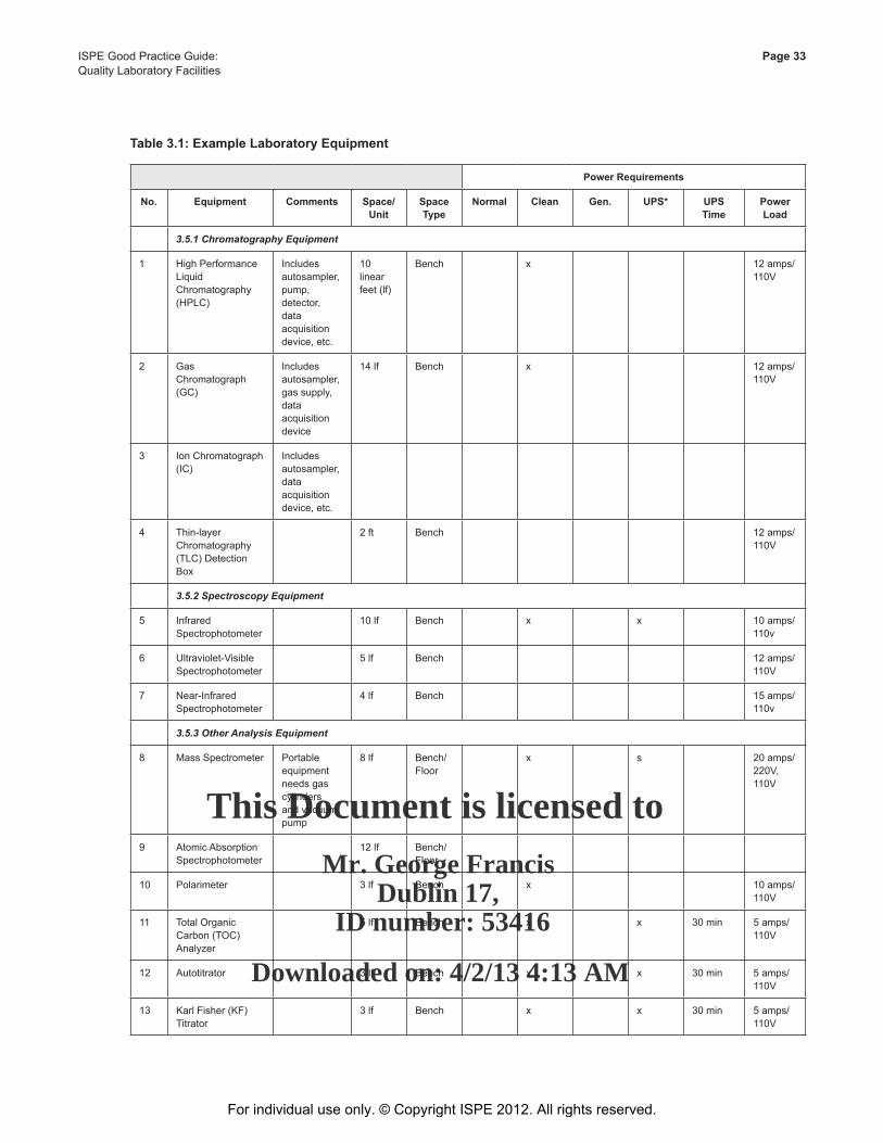
This Document is licensed to
Mr. George FrancisDublin 17,
ID number: 53416
Downloaded on: 4/2/13 4:13 AM
ISPE Good Practice Guide: Page 33Quality Laboratory Facilities
Table 3.1: Example Laboratory Equipment
Power Requirements
No. Equipment Comments Space/Unit
Space Type
Normal Clean Gen. UPS* UPS Time
Power Load
3.5.1 Chromatography Equipment
1 High Performance Liquid Chromatography (HPLC)
Includes autosampler, pump, detector, data acquisition device, etc.
10 linear feet (lf)
Bench x 12 amps/110V
2 Gas Chromatograph (GC)
Includes autosampler, gas supply, data acquisition device
14 lf Bench x 12 amps/110V
3 Ion Chromatograph (IC)
Includes autosampler, data acquisition device, etc.
4 Thin-layer Chromatography (TLC) Detection Box
2 ft Bench 12 amps/110V
3.5.2 Spectroscopy Equipment
5 Infrared Spectrophotometer
10 lf Bench x x 10 amps/110v
6 Ultraviolet-Visible Spectrophotometer
5 lf Bench 12 amps/110V
7 Near-Infrared Spectrophotometer
4 lf Bench 15 amps/110v
3.5.3 Other Analysis Equipment
8 Mass Spectrometer Portable equipment needs gas cylinders and vacuum pump
8 lf Bench/Floor
x s 20 amps/220V, 110V
9 Atomic Absorption Spectrophotometer
12 lf Bench/Floor
10 Polarimeter 3 lf Bench x 10 amps/110V
11 Total Organic Carbon (TOC) Analyzer
5 lf Bench x x 30 min 5 amps/110V
12 Autotitrator 3 lf Bench x x 30 min 5 amps/110V
13 Karl Fisher (KF) Titrator
3 lf Bench x x 30 min 5 amps/110V
For individual use only. © Copyright ISPE 2012. All rights reserved.
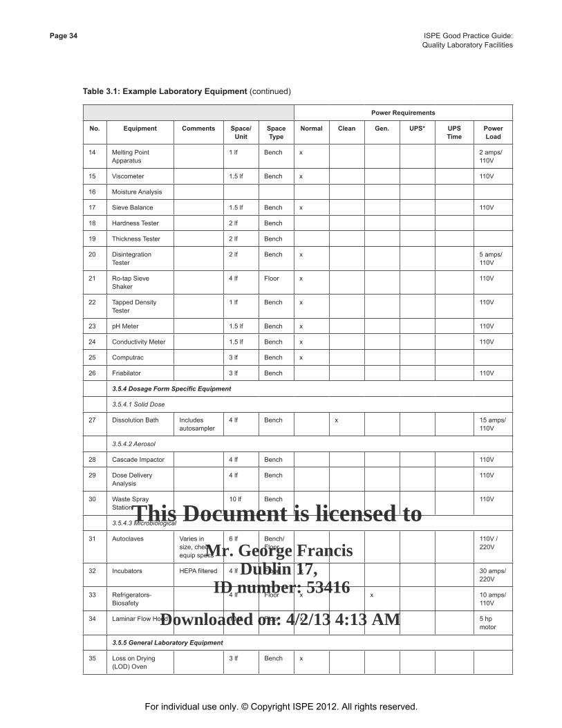
This Document is licensed to
Mr. George FrancisDublin 17,
ID number: 53416
Downloaded on: 4/2/13 4:13 AM
Page 34 ISPE Good Practice Guide: Quality Laboratory Facilities
Table 3.1: Example Laboratory Equipment (continued)
Power Requirements
No. Equipment Comments Space/Unit
Space Type
Normal Clean Gen. UPS* UPS Time
Power Load
14 Melting Point Apparatus
1 lf Bench x 2 amps/110V
15 Viscometer 1.5 lf Bench x 110V
16 Moisture Analysis
17 Sieve Balance 1.5 lf Bench x 110V
18 Hardness Tester 2 lf Bench
19 Thickness Tester 2 lf Bench
20 Disintegration Tester
2 lf Bench x 5 amps/110V
21 Ro-tap Sieve Shaker
4 lf Floor x 110V
22 Tapped Density Tester
1 lf Bench x 110V
23 pH Meter 1.5 lf Bench x 110V
24 Conductivity Meter 1.5 lf Bench x 110V
25 Computrac 3 lf Bench x
26 Friabilator 3 lf Bench 110V
3.5.4 Dosage Form Specific Equipment
3.5.4.1 Solid Dose
27 Dissolution Bath Includes autosampler
4 lf Bench x 15 amps/110V
3.5.4.2 Aerosol
28 Cascade Impactor 4 lf Bench 110V
29 Dose Delivery Analysis
4 lf Bench 110V
30 Waste Spray Station
10 lf Bench 110V
3.5.4.3 Microbiological
31 Autoclaves Varies in size, check equip specs
6 lf Bench/Floor
110V / 220V
32 Incubators HEPA filtered 4 lf Floor x 30 amps/220V
33 Refrigerators- Biosafety
4 lf Floor x x 10 amps/110V
34 Laminar Flow Hood 10 lf Floor x 5 hp motor
3.5.5 General Laboratory Equipment
35 Loss on Drying (LOD) Oven
3 lf Bench x
For individual use only. © Copyright ISPE 2012. All rights reserved.
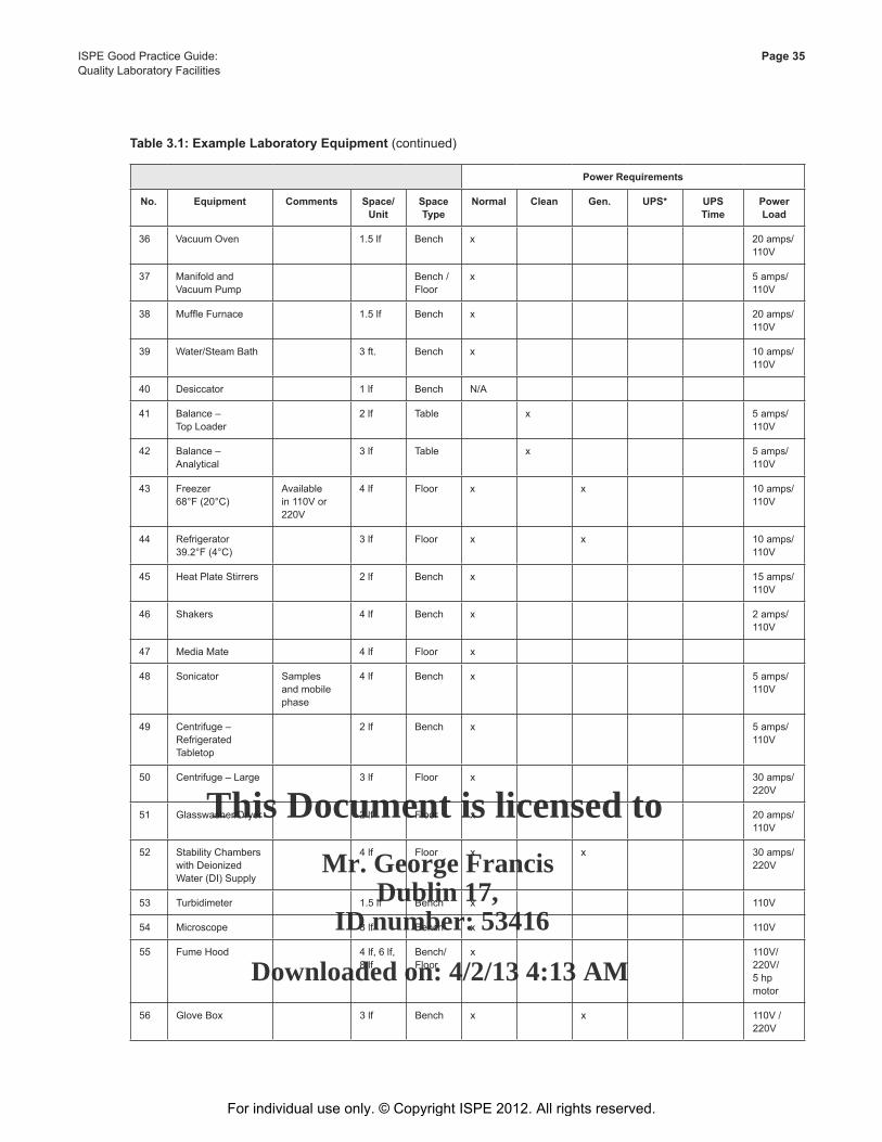
This Document is licensed to
Mr. George FrancisDublin 17,
ID number: 53416
Downloaded on: 4/2/13 4:13 AM
ISPE Good Practice Guide: Page 35Quality Laboratory Facilities
Table 3.1: Example Laboratory Equipment (continued)
Power Requirements
No. Equipment Comments Space/Unit
Space Type
Normal Clean Gen. UPS* UPS Time
Power Load
36 Vacuum Oven 1.5 lf Bench x 20 amps/110V
37 Manifold and Vacuum Pump
Bench / Floor
x 5 amps/110V
38 Muffle Furnace 1.5 lf Bench x 20 amps/110V
39 Water/Steam Bath 3 ft. Bench x 10 amps/110V
40 Desiccator 1 lf Bench N/A
41 Balance – Top Loader
2 lf Table x 5 amps/110V
42 Balance – Analytical
3 lf Table x 5 amps/110V
43 Freezer68°F (20°C)
Available in 110V or 220V
4 lf Floor x x 10 amps/110V
44 Refrigerator39.2°F (4°C)
3 lf Floor x x 10 amps/110V
45 Heat Plate Stirrers 2 lf Bench x 15 amps/110V
46 Shakers 4 lf Bench x 2 amps/110V
47 Media Mate 4 lf Floor x
48 Sonicator Samples and mobile phase
4 lf Bench x 5 amps/110V
49 Centrifuge – Refrigerated Tabletop
2 lf Bench x 5 amps/110V
50 Centrifuge – Large 3 lf Floor x 30 amps/220V
51 Glasswasher/Dryer 2 lf Floor x 20 amps/110V
52 Stability Chambers with Deionized Water (DI) Supply
4 lf Floor x x 30 amps/220V
53 Turbidimeter 1.5 lf Bench x 110V
54 Microscope 3 lf Bench x 110V
55 Fume Hood 4 lf, 6 lf, 8 lf
Bench/Floor
x 110V/220V/5 hp motor
56 Glove Box 3 lf Bench x x 110V / 220V
For individual use only. © Copyright ISPE 2012. All rights reserved.
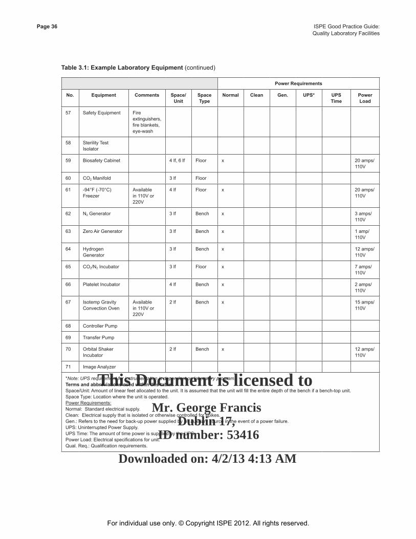
This Document is licensed to
Mr. George FrancisDublin 17,
ID number: 53416
Downloaded on: 4/2/13 4:13 AM
Page 36 ISPE Good Practice Guide: Quality Laboratory Facilities
Table 3.1: Example Laboratory Equipment (continued)
Power Requirements
No. Equipment Comments Space/Unit
Space Type
Normal Clean Gen. UPS* UPS Time
Power Load
57 Safety Equipment Fire extinguishers, fire blankets, eye-wash
58 Sterility Test Isolator
59 Biosafety Cabinet 4 lf, 6 lf Floor x 20 amps/110V
60 CO2 Manifold 3 lf Floor
61 -94°F (-70°C) Freezer
Available in 110V or 220V
4 lf Floor x 20 amps/110V
62 N2 Generator 3 lf Bench x 3 amps/110V
63 Zero Air Generator 3 lf Bench x 1 amp/110V
64 Hydrogen Generator
3 lf Bench x 12 amps/110V
65 CO2/N2 Incubator 3 lf Floor x 7 amps/110V
66 Platelet Incubator 4 lf Bench x 2 amps/110V
67 Isotemp Gravity Convection Oven
Available in 110V or 220V
2 lf Bench x 15 amps/110V
68 Controller Pump
69 Transfer Pump
70 Orbital Shaker Incubator
2 lf Bench x 12 amps/110V
71 Image Analyzer
*Note: UPS requirement for instrumentation is dependent on laboratory program.Terms and abbreviations used within this table:Space/Unit: Amount of linear feet allocated to the unit. It is assumed that the unit will fill the entire depth of the bench if a bench-top unit.Space Type: Location where the unit is operated.Power Requirements:Normal: Standard electrical supply.Clean: Electrical supply that is isolated or otherwise controlled for spikes.Gen.: Refers to the need for back-up power supplied by an auxiliary source in the event of a power failure.UPS: Uninterrupted Power Supply.UPS Time: The amount of time power is supplied by the UPS.Power Load: Electrical specifications for unit.Qual. Req.: Qualification requirements.
For individual use only. © Copyright ISPE 2012. All rights reserved.
This Document is licensed to
Mr. George FrancisDublin 17,
ID number: 53416
Downloaded on: 4/2/13 4:13 AM
ISPE Good Practice Guide: Page 37Quality Laboratory Facilities
4 Hazard and Safety4.1 Introduction
This Chapter addresses requirements for the use, design, and engineering of barrier or isolator technologies in quality laboratories. Functions, design, engineering, and operation of equipment and technologies that are used to protect the health and safety of the operators and the product during its final testing prior to release are considered. The use of the risk assessment (see Chapter 5 of this Guide) assists in determining the need for and type of microenvironment.
Traditionally, operators have been protected using PPE. PPE limited the time that operators could spend in a processing area, and equipment cleaning meant significant downtime. Organizations, such as OSHA, encourage the use of potent compound containment rather than relying on PPE.
Scientists and manufacturing personnel incur increased risks for occupational exposure to compounds during manufacturing and quality testing.
4.2 Occupational Exposure Limits
Understanding OELs is fundamental to the safe handling and storage of compounds. The OEL concept is used to quantify the toxic effects of compounds. It is a measure of the health effects of long-term occupational exposure to a compound. The OEL is the maximum concentration of a chemical (in air) to which personnel may be exposed for an eight hour work day, over a 40 hour work week, over a 40 year lifespan, resulting in no measurable adverse health effects.
The process of developing these limits for Active Pharmaceutical Ingredients (APIs) includes:
• Gathering data on the API and review its mechanism of activity
• Determining if the OEL can be established by analyzing the potential for primary carcinogenic effect
• Identifying risk factors
• Reviewing dosage range and mode of administration
• Classifying the API based on American Industrial Hygiene Association “Performance-Based Occupational Exposure Limits” [16]
For each substance and compound to be worked with in a quality laboratory, understanding the short and long-term exposure limits and hazards helps in the selection of the appropriate measures to be taken to minimize the possibility of exposure. Considerations include:
1. Acute versus chronic exposure:
• A single brief exposure
• Repeated long-term exposure over time 2. Route of exposure:
• Ingestion
For individual use only. © Copyright ISPE 2012. All rights reserved.
This Document is licensed to
Mr. George FrancisDublin 17,
ID number: 53416
Downloaded on: 4/2/13 4:13 AM
Page 38 ISPE Good Practice Guide: Quality Laboratory Facilities
• Inhalation
• Absorption
• Injection
3. Physical properties of the compound:
• Controlling fumes
• Controlling particles
• Controlling oxygen access
• Controlling humidity
• Controlling temperature
4. Nature of hazard:
• Does the compound affect the cardiovascular system?
• Does the compound affect the central nervous system?
• What are the appropriate first aid measures?
• Are the symptoms or injuries permanent or temporary?
5. In-use:
• Open system
• Closed system
6. In storage:
• How will the compounds be manipulated?
• In what quantities?
7. Material and personnel flow:
• Where are the compounds delivered?
• types of containers/packaging
• method of disposal
8. What is the laboratory process flow:
• Can handling and transport of the materials be minimized?
9. Gowning and PPE
For individual use only. © Copyright ISPE 2012. All rights reserved.
This Document is licensed to
Mr. George FrancisDublin 17,
ID number: 53416
Downloaded on: 4/2/13 4:13 AM
ISPE Good Practice Guide: Page 39Quality Laboratory Facilities
10. Equipment cleaning
Considerations for containment include:
• Separating personnel and material via directional airflow
• Providing decontamination showers or misters in personnel airlocks
• Evaluating paperless technologies
• Monitoring environmental conditions:
- RH
- Temperature
- Pressure/directional airflow
• HEPA air filtration on supply and exhaust
• Maintaining the appropriate air change rates
• HEPA filter replacement technologies designed to protect the maintenance staff as well as the environment
• Containment and management of effluent
• Ensuring ergonomic issues are closely considered
The Environmental, Health, and Safety (EHS) Department or Safety Officer should assess risks to employees. It is considered good practice that an Environmental Engineer and/or Chemical Engineer provide substance classifications and a Hazardous Materials Master Plan along with a chemical summary list. This information is used by the laboratory staff to determine SOPs and by the facility design team to ensure that the room classification is correct with respect to building codes and systems design.
The goal is to ensure that adequate and correct information is gathered and ready for use before the laboratory is designed, constructed, and occupied. This includes Material Safety Data Sheets (MSDSs), hazardous material reports and all pertinent regional and industry guidelines and regulations applicable to the design and/or use of the laboratory. Once the answers to these questions are analyzed, proper equipment and systems can be established.
4.2.1 Isolators
Isolator technologies come in a variety of designs. Their primary function is to create microenvironments that contain or protect products and maintain the health and safety of the operators. Detailed design guidance and recommendations are given based on the type of microenvironment necessary. Additional factors to consider prior to the selection of a specific technology include:
• Risk assessment
• Schedule • Budget
• Reliability
For individual use only. © Copyright ISPE 2012. All rights reserved.
This Document is licensed to
Mr. George FrancisDublin 17,
ID number: 53416
Downloaded on: 4/2/13 4:13 AM
Page 40 ISPE Good Practice Guide: Quality Laboratory Facilities
• Availability
• Flexibility
Isolator systems can be used for aseptic processing activities or containment of potent compounds or simultaneously for both asepsis and containment. Open isolators (aseptic isolators) use positive airflow and allow for continuous or semi-continuous ingress/egress of materials, while maintaining a level of protection over the internal environment. Closed isolators (containment isolators) use negative pressure, and are capable of levels of separation between the internal and external environment.
An understanding of the laboratory macro-environment and in particular, the HVAC system, is critical in the selection of the micro-environmental technology. In addition, familiarity with regulations concerning the specific hazardous compounds being used is assumed, including:
• BMBL for biological hazards [17]
• NFPA for chemical hazards [18]
• NRC for radiological hazards [19]
• USDA for agricultural hazards [20]
Integral isolator systems associated with particulate-generating steps, such as fill, tablet, and mixing systems, avoiding the challenge of structural, ergonomic, access, MEP, and service integration involved with mating unrelated systems. Such systems require intense cooperation between multiple vendors to provide an integrated system.
Powder containment rooms offer alternatives to isolator systems. These rooms act much like biological safety cabinets, drawing room air over the process zone and away from workers and deliver the air back to the room generally requiring an inflow of fresh air around 10% of the system airflow to help control the airflow direction.
Regardless of the engineered control that is chosen to minimize exposure, every technology needs proper implementation and training.
Similar to production facilities, the primary and (if necessary) secondary means of containment or isolation can be determined. The following are exposure control elements that can be considered in designing quality laboratories:
1. Fume hood or Class III safety cabinets deemed adequate given the nature and severity of the hazard
2. Isolators with glove ports
3. Docking ports installed at these isolators so that protective outer packaging can be removed before use within the protective environment
4. Breathing air as back-up precaution to primary containment
5. Toxic or potent compound put into solution may be safe to handle outside a Class III safety cabinet or isolator
6. Exhaust stream from the hoods and isolators, and perhaps the room may require treatment before release:
• Fumes may require chemical adsorption media, carbon, or water filtration.
• Particulates may have to be removed by filtration.
For individual use only. © Copyright ISPE 2012. All rights reserved.
This Document is licensed to
Mr. George FrancisDublin 17,
ID number: 53416
Downloaded on: 4/2/13 4:13 AM
ISPE Good Practice Guide: Page 41Quality Laboratory Facilities
7. Recessed ceiling sprinkler heads used to minimize dust and microbial accumulation in BSL and bio-clean room facilities. It also maximizes the ease to apply surface disinfection or sanitization solutions by a mop or sponge application.
8. Once the isolator or hood is used – how will it be cleaned?
9. What is the nature of the laboratory waste and how will it be collected and/or disposed of?
10. If the laboratory is the means of containment, is an airlock or gowning/degowning vestibule needed?
11. Room pressurization levels and airflow requirements should be established.
12. In the event that there is an exposure:
• What will you do?
• What procedures and response measures are in place?
13. As with all spaces, appropriate signage should be in place to identify the hazards present.
14. When there may be a conflict between GLP/GMP requirements and safety requirements – both GxP and safety requirements should be considered.
15. What would be the impact of equipment failure?
4.2.2 Pressurization for Barrier or Containment
The need to provide a contained environment is the key reason to consider isolator technology. The techniques for creating a contained environment within an isolator is similar to those used for facilities although the air quantities are generally smaller and can be controlled at greater precision at a lower cost.
Barrier systems may be designed as positive pressure: to protect the product, or negative pressure: to protect the operator. The pressure in the local environment can similarly be surrounded by positive pressure as a means of providing isolation.
The design should consider the primary objective and design the area pressurization accordingly, see Chapter 8 of this Guide on HVAC.
This technique is useful for handling processes that are designed to protect product or process from contamination from personnel or ambient conditions. Typical applications would include:
• Aseptic processing
• Tissue and cell culture
• Filling and capping operations
• Some packaging applications
In selecting or designing an isolator application, it is important to determine whether a barrier, containment, or combination environment is needed. Different configurations are specified according to the application.
For individual use only. © Copyright ISPE 2012. All rights reserved.
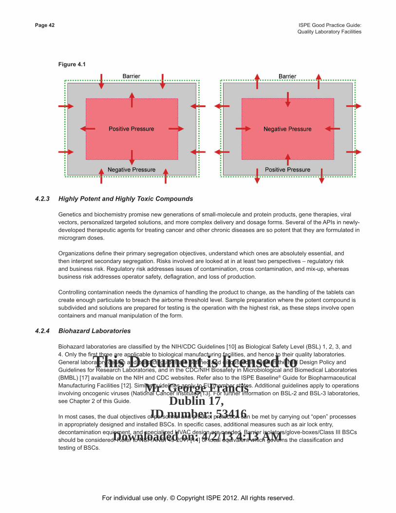
This Document is licensed to
Mr. George FrancisDublin 17,
ID number: 53416
Downloaded on: 4/2/13 4:13 AM
Page 42 ISPE Good Practice Guide: Quality Laboratory Facilities
Figure 4.1
4.2.3 Highly Potent and Highly Toxic Compounds
Genetics and biochemistry promise new generations of small-molecule and protein products, gene therapies, viral vectors, personalized targeted solutions, and more complex delivery and dosage forms. Several of the APIs in newly-developed therapeutic agents for treating cancer and other chronic diseases are so potent that they are formulated in microgram doses.
Organizations define their primary segregation objectives, understand which ones are absolutely essential, and then interpret secondary segregation. Risks involved are looked at in at least two perspectives – regulatory risk and business risk. Regulatory risk addresses issues of contamination, cross contamination, and mix-up, whereas business risk addresses operator safety, deflagration, and loss of production.
Controlling contamination needs the dynamics of handling the product to change, as the handling of the tablets can create enough particulate to breach the airborne threshold level. Sample preparation where the potent compound is subdivided and solutions are prepared for testing is the operation with the highest risk, as these steps involve open containers and manual manipulation of the form.
4.2.4 Biohazard Laboratories
Biohazard laboratories are classified by the NIH/CDC Guidelines [10] as Biological Safety Level (BSL) 1, 2, 3, and 4. Only the first three are applicable to biological manufacturing facilities, and hence to their quality laboratories. General laboratory design and practice guides are outlined and discussed in detail in the NIH Design Policy and Guidelines for Research Laboratories, and in the CDC/NIH Biosafety in Microbiological and Biomedical Laboratories (BMBL) [17] available on the NIH and CDC websites. Refer also to the ISPE Baseline® Guide for Biopharmaceutical Manufacturing Facilities [12]. Similar guidelines apply to EU member states. Additional guidelines apply to operations involving oncogenic viruses (National Cancer Institute) [13]. For further information on BSL-2 and BSL-3 laboratories, see Chapter 2 of this Guide.
In most cases, the dual objectives of personnel and product protection can be met by carrying out “open” processes in appropriately designed and installed BSCs. In specific cases, additional measures such as air lock entry, decontamination equipment, and specialized HVAC design are needed. Barrier isolators/glove-boxes/Class III BSCs should be considered. Refer to NSF/ANSI 49-2011 [14] or local equivalent which governs the classification and testing of BSCs.
For individual use only. © Copyright ISPE 2012. All rights reserved.
This Document is licensed to
Mr. George FrancisDublin 17,
ID number: 53416
Downloaded on: 4/2/13 4:13 AM
ISPE Good Practice Guide: Page 43Quality Laboratory Facilities
4.2.5 Physical Hazards
Some chemicals, gasses, and support systems present physical hazards that should be addressed in the scope development and design phase of the project. Internal storage of pressurized or liquefied gases also present potential asphyxiation risks. Prevention and/or detection should be considered during risk assessment. In some cases, the chemicals and gasses can create explosion hazards if not properly handled and stored. If addressed early on, systems can be engineered to minimize the impact on the facility and personnel.
Building regulations are generally primarily concerned with fire. Flammable substances, oxidizers, and organic peroxides present additional risks that require management.
The International Fire Code (IFC) [21] designates the use an IFC category H3 for flammable liquids, oxidizers, and organic peroxides that pose a physical hazard. Flammable liquids used in open containers or with very low flash points (< 73°F/< 22.8°C) and boiling points (< 100°F/< 37.8°C) are considered a deflagration hazard, H2.
The EHS Department, Safety Officer, Environmental/Chemical Engineering team should be involved in establishing the nature and severity of the hazard present based upon each chemical, compound, and gas to be used. For further information regarding highly potent and highly toxic compounds, see Chapter 4 of this Guide. A study of the solvent loading, storage, and use on the testing floor needs to be conducted to determine the loading and subdivision of the laboratory to meet fire codes as well as to have adequate storage facilities for back up supply as well as waste. The emergence of the International Building Code (IBC) [22] has allowed a more consistent analysis of hazards from jurisdiction to jurisdiction. The IBC establishes building uses that affect construction type and allowable building height and area. The use of toxic and flammable substances is more fully addressed in the companion International Fire Code. However, many jurisdictions or state fire marshal’s offices may choose the National Fire Protection Association’s reference code 1 (NFPA 1: Fire Code) [23].
A careful analysis of the use of the chemicals in a facility may allow keeping them below exempt amounts allowed by the code. The definition of the areas where exempt amounts are stored or used is defined as a control area. Amounts of toxic and highly toxic materials may be large, requiring the definition of the facility as H4. However, flammable liquids may be used in small amounts for cleaning, dryers, and instrumentation. For further information see the International Building Code (IBC) [22].
A differentiation between explosion and deflagration is important because the code addresses each differently. A deflagration is rapid oxidation and moves at a subsonic speed. Non-exempt amounts should be placed in an H2 use. An explosion or detonation moves at a supersonic speed. Non-exempt amounts should be placed in a H1 use area. This has important considerations for the building design because the subsonic deflagration can be vented. H2 uses require deflagration analysis; venting that release deflagration pressures, and interior walls that resist the deflagration pressures. The IBC allows a pressure resistance of up to 216 psf (1.5 psi) for these interior walls which pose a structural challenge with expensive solutions. H1 uses are rare and strong consideration should be made to store and use these materials in a separate facility.
A control area can be an entire building, a floor or any demarcation desired by the designer; depending on the amounts of exempt materials. The areas designated should be defined by rated construction. Usually the fire barrier is rated one hour; on the fourth level and above this rating becomes two hours. In addition, only four control areas are allowed per the first floor, this number diminishing as the height of the level increases.
Note: the floor of a control area usually needs a two hour floor (see the International Building Code (IBC) [22]. Establishing a suitable building use needs proper definition of the hazard in order to assure a safe and cost effective solution. Wherever possible, laboratories are designed as a non-hazardous occupancy classification to avoid additional building code restrictions and requirements. The code assigns toxic and highly toxic materials to a Hazard Level H4 for materials that pose a health hazard. The IBC definitions of toxic and highly toxic may be considered simple when compared to the exposure control bands typical to a pharmaceutical facility. However, the IBC code does not impose a penalty on construction type for toxic and highly toxic H4 uses. H4 has allowable heights and areas similar to F-1 Moderate Hazard Industrial, or S-1 Moderate-Hazard Storage uses depending on the construction type.
For individual use only. © Copyright ISPE 2012. All rights reserved.

This Document is licensed to
Mr. George FrancisDublin 17,
ID number: 53416
Downloaded on: 4/2/13 4:13 AM
Page 44 ISPE Good Practice Guide: Quality Laboratory Facilities
Chemicals such as isopropyl alcohol (IPA) or toluene and other organic solvents present a unique challenge as their vapors are heavier than air. These fumes can roll down a work surface and accumulate at the floor level. Room exhaust should be placed low in the room at floor level to prevent vapor accumulation, and electrical outlets, switches, motors, lighting, and fixtures should be explosion-proof to avoid being a potential source of ignition. Sources of heat are kept away from these chemicals. Standard operating procedure in a quality laboratory that handles these types of substances should require that they are handled in the fume hood. Where large quantities are to be mixed, stored, and dispensed for general use such as the pre mixed mobile phase for HPLC analysis, design this area to have the appropriate safeguards for mixing, storing, and dispensing.
Hydrogen gas also presents an explosion hazard. As much as possible, this gas should be used in as small a quantity as practical and in a closed system, or within a hood to contain the gas. Hydrogen in the quality laboratory is likely used for flame ionization detectors for GCs. The hydrogen is usually supplied from a cylinder inside a cylinder cabinet designed for this gas located adjacent to the instrument. Alternately, hydrogen generators may be used, directly piped to the instrument with an automatic shutoff in case of a leak. Hydrogen sensors connected to an alarm system can be placed within the room to detect rising levels of hydrogen gas.
Some flammable/combustible chemicals are not extinguished, but rather spread or are actually ignited by sprinkler water. Should materials of this type be used in a laboratory, active wet sprinklers should be avoided. An alternative type of automatic fire suppression system should be provided- such as a dry chemical or gaseous suppression. Foam or other types of extinguishers also may be provided within the room. Fire Department officials and/or the Local Fire Marshal should be involved in the discussions regarding what types of systems to employ as well as response measures to be taken in the event of an accident. Risk assessments should address the specific hazards and risks of the materials, use, and operations. The information from the risk assessment should be used in determining the appropriate fire protection and prevention methods. Local codes and authorities having jurisdiction also will influence the design criteria.
Personnel with pacemakers should be careful not to enter Nuclear Magnetic Resonance (NMR) suites where they might enter the equipment’s magnetic field or gauss line limits. Non-ferrous material also should be employed as much as possible in proximity to this equipment. Signs, SOPs, and proper training should be used to educate and inform personnel regarding the hazards specific to NMR equipment.
Exposure to radiation is another hazard. Low level radioisotopes should be relegated to alcoves or isolation laboratories – certain materials should only be handled in radioisotope hoods. Other types of equipment, such as some X-ray units may require lead linings behind drywall or shielding within the room.
4.2.6 Signage
Signage at the entrance and within the laboratory should alert personnel to the potential hazards within a laboratory. This is important both to scientific personnel and to maintenance and outside support personnel.
For individual use only. © Copyright ISPE 2012. All rights reserved.
This Document is licensed to
Mr. George FrancisDublin 17,
ID number: 53416
Downloaded on: 4/2/13 4:13 AM
ISPE Good Practice Guide: Page 45Quality Laboratory Facilities
5 Risk Assessment5.1 Introduction
The purpose of quality testing is to assure manufactured products meet the identity, strength, purity, and safety as specified in an approved regulatory file. Testing also is performed in a quality laboratory to establish the stability baseline of materials and products, for initial material release, for in-process verifications, and to investigate product complaints.
Typically, when a quality test fails, i.e., the product fails to meet specifications, the material should be quarantined, rejected, or subjected to further test procedures or rework. Conversely, risk to patient safety may exist when a test function fails to detect an Out of Specification (OOS) product. This type of failure may be derived from laboratory conditions or because of a support system malfunction.
Regulatory initiatives and guidelines emphasize the principles of risk management and the application of these techniques to pharmaceutical facility inspections and submission review. For a laboratory and its associated utilities and support systems, a documented risk assessment can identify those areas or systems having an impact on product quality and quality control functions, and provide a rationale for commissioning, verification, and qualification decisions.
The ASTM Standard E2500 [24] and the ISPE Baseline® Guide on Commissioning and Qualification [25], promote the application of risk-based assessments to determine the impact or risk of a given system on product quality. Assessments can be used to determine a qualification plan for any applicable systems.
Note: a quality laboratory verifies product quality and typically, does not affect product quality. The criteria for determining system impact and component criticality as defined by the ISPE Baseline® Guide on Commissioning and Qualification [25] cannot be directly applied to a quality laboratory.
A risk assessment should be employed to develop appropriate criteria for determining system impact and component criticality for a quality laboratory project. Additional guidance on determining impact criteria can be found in the ISPE GAMP Good Practice Guide: Validation of Computerized Laboratory Systems [26]. However, this GAMP guidance focuses primarily on the impact to data quality and integrity.
Guidance is provided on how to apply a risk assessment to a quality laboratory facility and identify issues to be considered when conducting the risk assessment. A risk assessment is an element of an overall risk management strategy. Risk management allows a consistent and science-based approach to decision making, across the life cycle of a product or project. For further information on how to conduct and document a risk assessment, see ICH Q9 [27].
Risk assessments should be performed prior to, or during, the detailed design stage for a new or renovated facility as part of the enhanced design review or at design qualification, see the Baseline® Guide on Commissioning and Qualification. [25]
Using requirements and design documentation, a review of the intended purpose of a laboratory area or the type of testing to be performed in a laboratory area may identify potential risks inherent in the design. For example, a test area may not be adequately segregated from manufacturing or sample receiving to prevent cross contamination. An assessment also may reveal that a laboratory space is insufficient for the planned storage or staging of samples and reagents for testing, potentially leading to inadequate storage conditions or mix up. While in the design phase, appropriate mitigation of the identified risks can be made; therefore preventing the potential for quality issues. When employed early in a project, risk mitigation through design changes can be more cost effective and have less impact on project schedules.
For individual use only. © Copyright ISPE 2012. All rights reserved.
This Document is licensed to
Mr. George FrancisDublin 17,
ID number: 53416
Downloaded on: 4/2/13 4:13 AM
Page 46 ISPE Good Practice Guide: Quality Laboratory Facilities
The criteria used to assess risk and the risk assessment itself should be documented. This provides a traceable rationale for both design qualification, where needed, and the development of impact assessment criteria and the verification strategy for a project.
5.2 Regulatory Review
A review of regulatory guidance documents for requirements of laboratory systems is as follows:
• CFR Section 211.160 [3] states that “The calibration of instruments, apparatus, gauges, and recording devices at suitable intervals in accordance with an established written program containing specific directions, schedules, limits for accuracy and precision, and provisions for remedial action in the event accuracy and/or precision limits are not met. Instruments, apparatus, gauges, and recording devices not meeting established specifications shall not be used.”
• The current good laboratory practice regulations, 21 CFR Part 58.61 [28] impose similar requirements stating that “equipment used for the generation, measurement, or assessment of data shall be adequately tested, calibrated, and standardized.”
• EudraLex Volume 4 – Guidelines for Good Manufacturing Practices for Medicinal Products for Human and Veterinary Use (2008 Edition) [5] states that “Measuring, weighing, recording and control equipment should be calibrated and checked at defined intervals by appropriate methods. Adequate records of such tests should be maintained.”
• ICH Q9 – Quality Risk Management [27]. This document contains a systematic approach to quality risk management, including risk assessment. ICH Q9 is a guidance document meant to help the industry. It is recommended that ICH Q9 be consulted prior to determining any laboratory risk assessment strategy.
5.3 Assessing Risk
A risk assessment has been defined as a “methodology, conducted during the scope and design development of the facility, to determine, analyze, and manage potential risks to product quality in the ISPE Guide: Science and Risk-Based Approach for the Delivery of Facilities, Systems, and Equipment [29]. For the quality laboratory facility, this definition can be extended to include the potential risks to corporate reputation and profits and also the potential risks to personnel or sample safety. While these are not considered to be regulatory risks, they are still risks to consider when determining the verification strategy. To accurately perform a risk assessment for the quality laboratory, there should be an understanding of the purpose of these facilities and the functions contained within.
There are many different types of samples which can be sent to a quality laboratory for many different types of testing. The types of samples and testing which are expected in a given laboratory facility should be understood in detail, prior to conducting the risk assessment.
A risk assessment of the intended use and function of a laboratory, utility, or support system should determine potential risk to a quality function or outcome, which could result in the erroneous generation of an OOS test result or release of an OOS product.
To arrive at meaningful conclusions, the assessment procedure needs a thorough understanding and review of what can fail, the consequences of that failure or subsequent failures on the QC function, and an analysis of the control systems or procedures in place that will detect or prevent the failure. For example, the risk associated with loss of power should be considered. Many different areas of a laboratory facility could be affected or compromised in the event of a power failure. Potential risks, such as loss of HVAC in controlled areas, affects on analytical equipment related to power loss and restart, restricted electronic security access, sample, or personnel safety related to specialty containment systems, should be understood. Identification of these types of risks will help in the planning for backup and emergency power and also will help to determine the level of testing needed for such systems.
For individual use only. © Copyright ISPE 2012. All rights reserved.
This Document is licensed to
Mr. George FrancisDublin 17,
ID number: 53416
Downloaded on: 4/2/13 4:13 AM
ISPE Good Practice Guide: Page 47Quality Laboratory Facilities
It is not the intent of this Guide to define how to conduct a risk assessment or which risk assessment method to use as there is a lot of guidance already in existence; however, an example of an FMEA approach is provided.
In FMEA, each risk has two primary elements, the probability of a given failure occurring, and the severity of the failure if it occurs; these two elements together define each risk. In addition, it may be beneficial to include the ability to detect the risk or hazard. Typically, all three elements are used in the quantitative analysis of risk. Quantitative risk may be referred to as the Risk Priority Number (RPN).
RPN = Probability × Severity × Detectability
Before performing a risk assessment, the organization should establish criteria for assessing the risk, including what level of risk is acceptable, and what level of risk needs remediation or mitigation actions. The level at which risk becomes unacceptable to the organization may be defined by RPN. It is important to note there is no industry or regulatory standards defining the acceptability levels for risk. Organizations should define a scale and acceptable ranges. The rationale for defining the acceptability of risk should be documented. The risk assessment can be used as an impact assessment to determine the degree of testing for the laboratory systems, including how the system should be verified.
High risk systems are usually those which come in contact with the samples and can affect test or data validity.
Medium risk systems are usually those which are not expected to have a direct impact on samples or affect test/data validity, but typically will support a high risk system.
Low or no risk systems are those which support the facility, but are not expected to have any impact on samples or affect test/data validity. For further information on how to develop an appropriate verification strategy, based on the results of the risk assessment, see Chapter 11 of this Guide.
User requirements should be defined for the facility infrastructure and systems, and for each type of laboratory functionality that will be contained within the facility (e.g., analytical testing, microbiological testing, or stability studies) in order to conduct an assessment. Organizations should determine a standard for creation of user requirements. User requirements may be generated on a system by system basis or captured in more general terms for an entire facility. After systems have been classified, it may be prudent to revisit the user requirements for high risk systems with more detail added as appropriate.
Questions to be asked in determining user requirements may include:
• What functions will occur in each laboratory space?
• Are there regulatory requirements governing any of these functions?
• What are the types and volumes of samples expected?
• What equipment will be located in the area and how will its operation affect the laboratory environment?
• Does the system produce data evaluated to accept or reject product?
• Does the system produce in-process data evaluated to move from step to step in the manufacturing process?
• Does the system produce data evaluated to establish regulatory stability?
• What are the expected uses of, and the associated criticality of, the utility or support systems?
• What protective devices are necessary for product protection?
For individual use only. © Copyright ISPE 2012. All rights reserved.

This Document is licensed to
Mr. George FrancisDublin 17,
ID number: 53416
Downloaded on: 4/2/13 4:13 AM
Page 48 ISPE Good Practice Guide: Quality Laboratory Facilities
• What protective devices are necessary for personnel protection?
User requirements should be used as the basis for facility design and for assessing the verification requirements of the facility, utilities, and equipment. Depending on the system or functionality being evaluated, these user requirements can originate from scientific, quality, engineering, maintenance, automation, or information technology functions. User requirements should capture all regulatory requirements for systems and functions, as well as operating, safety and equipment parameters, and maintenance requirements.
It is important to remember that this Guide focuses on the utilities and equipment related to the laboratory facility. While a risk assessment also may be useful for determining the verification strategy for laboratory equipment and instrumentation, it is outside the scope of this Guide.
Once user requirements are defined and a preliminary design of all systems has occurred, each system should be individually and collectively evaluated for risk. Regulatory and business risks, as well as safety risks should be considered. While business and safety risks do not require verification, they can be important risks to be assessed as part of the laboratory project.
Risk assessment is not a onetime activity. When there is a change to either the user requirements or the design, the risk should be re-assessed with respect to the change to ensure that the verification strategy is still appropriate.
Risk assessment, risk management, and quality control principles are applied in all industries to improve efficiencies, increase reliability, comply with applicable regulations, reduce costs, and improve safety. For further information on the commissioning and qualification process for quality laboratories and the types of activities and deliverables to consider when developing a verification strategy, see Chapter 11 of this Guide.
For individual use only. © Copyright ISPE 2012. All rights reserved.
This Document is licensed to
Mr. George FrancisDublin 17,
ID number: 53416
Downloaded on: 4/2/13 4:13 AM
ISPE Good Practice Guide: Page 49Quality Laboratory Facilities
6 The Project Execution6.1 The Laboratory Design Process
Quality laboratories are an integral part of the pharmaceutical manufacturing process. Responsibilities range from establishing product stability to testing of the incoming packaging components, raw materials, and providing final product release. Quality laboratories establish and confirm that all components supporting the product meet specifications, assuring safety to patients.
Laboratory design involves:
• The formation of teams to conduct the process
• The implementation of project management tools, including scheduling, budget management, management of the project scope and client expectations, and change management
• A knowledge of the stages of design and the evolving definition of the facility
• The understanding of the basics of architectural design for a regulated environment
• An understanding of the basics of laboratory layout and functionality
• An understanding of the process of quality control and stability testing
As with the manufacturing process, the design of laboratories needs an understanding of and attention to the protection needed for both the product and the personnel.
The laboratory design process provides the mechanism for designing a new laboratory or renovating an existing laboratory. The design phase of a project is where the team members execute their responsibility to effectively influence and determine the outcome of that project. User representatives should share their unique vision of their laboratory with the design consultant. The programming process should identify clearly the purpose and scope of a project. Detailed design should further define and refine building layouts. The result of these efforts is a common understanding of the facility and the establishment of a collaborative working relationship for the duration of the project.
Figure 6.1 shows the major stages of a facilities project. Once the facility need has been identified, the scope for the facility can be defined. For quality laboratories, this defines the services to be provided and the activities necessary to perform those services. For example, a small API manufacturing site may require only a few laboratories for raw materials, in-process, and API testing. Alternatively, a larger site could include all these activities plus product testing, package/component testing, and stability testing.
For individual use only. © Copyright ISPE 2012. All rights reserved.

This Document is licensed to
Mr. George FrancisDublin 17,
ID number: 53416
Downloaded on: 4/2/13 4:13 AM
Page 50 ISPE Good Practice Guide: Quality Laboratory Facilities
Figure 6.1: Major Project Stages
6.1.1 Programming
Programming (also called concept development) encompasses the series of activities that lead to the determination of the scope and design criteria for a facility. It is the foundation of a project and is the information gathering stage where client groups should be interviewed, industry standards discussed, and specific laboratory layout requirements determined. Programming is the first opportunity for the owner’s representatives as team members to share their vision with the design team leader and other project team members. User requirements should be defined during programming.
Scheduled team meetings should be arranged, in which input is presented from quality personnel and various support groups, including:
• Quality Operations
• Site EHS
• Regulatory and Analytical Sciences
• Facility and Utilities Services
• Information Systems
• Operational Services
• Financial Services
• LIMS and Automation
6.1.2 Schematic Design
Schematic design defines an overall plan for a laboratory facility. Information should be compiled for individual laboratory layouts, their adjacencies to support, office and public spaces, corridors, materials, and personnel flows. The engineering efforts at this stage focus on general utility distributions and the definition of unique utility requirements. At the conclusion of programming and schematic design, the design team should have adequate information to:
• Describe the proposed laboratory facility in text and with floor plans
For individual use only. © Copyright ISPE 2012. All rights reserved.
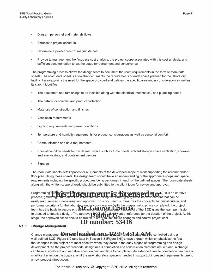
This Document is licensed to
Mr. George FrancisDublin 17,
ID number: 53416
Downloaded on: 4/2/13 4:13 AM
ISPE Good Practice Guide: Page 51Quality Laboratory Facilities
• Diagram personnel and materials flows
• Forecast a project schedule
• Determine a project order of magnitude cost
• Provide to management the first-pass cost analysis, the project scope associated with this cost analysis, and sufficient documentation to set the stage for agreement and concurrence
The programming process allows the design team to document the room requirements in the form of room data sheets. The room data sheet is a tool that documents the requirements of each space planned for the laboratory facility. It also explains the need for the space provided and defines the specific area under consideration as well as its size. It identifies:
• The equipment and furnishings to be installed along with the electrical, mechanical, and plumbing needs
• The details for scientist and product protection
• Materials of construction and finishes
• Ventilation requirements
• Lighting requirements and power conditions
• Temperature and humidity requirements for product considerations as well as personal comfort
• Communication and data requirements
• Special condition needs for the defined space such as fume hoods, solvent storage space ventilation, showers and eye washes, and containment devices
• Signage
The room data sheets detail spaces for all elements of the developed scope of work supporting the recommended floor plan. Using these sheets, the design team should have an understanding of the appropriate scope and space requirements including the specific procedures being performed in each of the defined spaces. The room data sheets, along with the written scope of work, should be submitted to the client team for review and approval.
Programming through schematic design is the process of developing the Basis of Design (BOD). It is an iterative process, gathering information that is restated in descriptive terms, giving the client a document that can be easily read, revised if necessary, and approved. This document summarizes the concepts, technical criteria, and performance criteria for the laboratory under consideration. With the programming phase completed, the project team has the basis to secure end user concurrence. Management approval of the BOD gives the team permission to proceed to detailed design. The approved BOD is the document of reference for the duration of the project. At this stage, the approved scope should be frozen in order to limit future changes and control project cost.
6.1.3 Change Management
Change management is important throughout a facilities project. Project change may be controlled using a well-defined BOD. Figure 6.2 (and later in Section 6.8 (Figure 6.6)) shows a graph which emphasizes the fact that changes to the project are most effective when they occur in the early stages of programming and design development. As the project proceeds, design nears completion and construction elements are in place, a change can have a significant and negative effect on cost and time to completion. An extended time to completion can have a significant effect on the corporation if the new laboratory space is needed in support of increased requirements due to a new product introduction.
For individual use only. © Copyright ISPE 2012. All rights reserved.
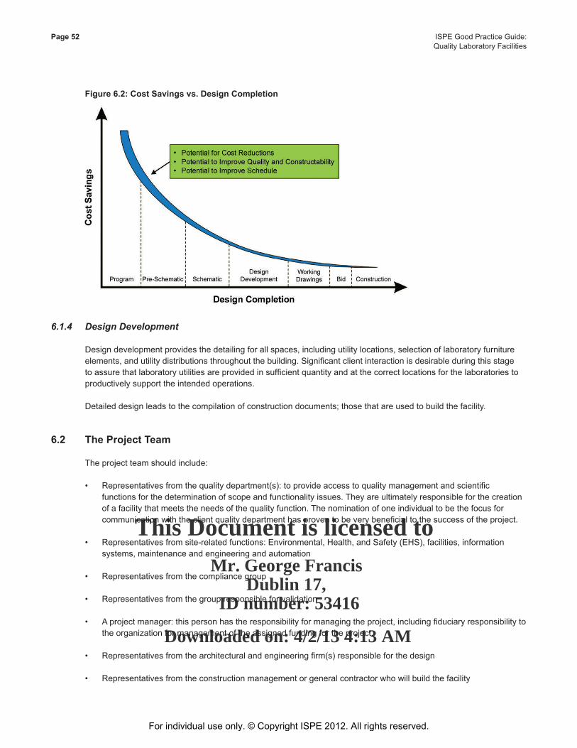
This Document is licensed to
Mr. George FrancisDublin 17,
ID number: 53416
Downloaded on: 4/2/13 4:13 AM
Page 52 ISPE Good Practice Guide: Quality Laboratory Facilities
Figure 6.2: Cost Savings vs. Design Completion
6.1.4 Design Development
Design development provides the detailing for all spaces, including utility locations, selection of laboratory furniture elements, and utility distributions throughout the building. Significant client interaction is desirable during this stage to assure that laboratory utilities are provided in sufficient quantity and at the correct locations for the laboratories to productively support the intended operations.
Detailed design leads to the compilation of construction documents; those that are used to build the facility.
6.2 The Project Team
The project team should include:
• Representatives from the quality department(s): to provide access to quality management and scientific functions for the determination of scope and functionality issues. They are ultimately responsible for the creation of a facility that meets the needs of the quality function. The nomination of one individual to be the focus for communication with the client quality department has proven to be very beneficial to the success of the project.
• Representatives from site-related functions: Environmental, Health, and Safety (EHS), facilities, information systems, maintenance and engineering and automation
• Representatives from the compliance group
• Representatives from the group responsible for validation
• A project manager: this person has the responsibility for managing the project, including fiduciary responsibility to the organization for management of the assigned funding for the project.
• Representatives from the architectural and engineering firm(s) responsible for the design
• Representatives from the construction management or general contractor who will build the facility
For individual use only. © Copyright ISPE 2012. All rights reserved.
This Document is licensed to
Mr. George FrancisDublin 17,
ID number: 53416
Downloaded on: 4/2/13 4:13 AM
ISPE Good Practice Guide: Page 53Quality Laboratory Facilities
Individuals from each of these groups should have specific assignments with clearly defined responsibilities.
Strategic individuals participate in the entire process. Other individuals participate on an as-needed basis when the design process is concentrating on a specific area requiring a special discipline. The project team should be empowered with establishing the execution strategy along with the decisions needed to reach consensus. They should have decision-making authority for the process along with conflict resolution responsibilities.
For every facility project, there are two clients:
• Those who work in the facility – the scientists, technicians, and their management
• Those who work on the facility – EHS, site facilities management, information systems, maintenance and engineering, automation
These individuals will interact with the facility for many years. Figure 6.3 depicts (with bullets) the extent of these client impacts. The success of a facility may be determined by their collaboration during the design. Their participation should be empowered by their respective management and should be considered as an important part of their overall job responsibilities.
Involvement of the constructor (construction management firm or general contractor) is important during the design. These professionals will review the evolving design and make comments on constructability issues as well as offering advice concerning less costly ways of building the project. As shown in Figure 6.2, the earlier constructability issues are identified, the more positive the impact on project schedule and budget.
Figure 6.3: Project Information Milestones with Client Impacts
For individual use only. © Copyright ISPE 2012. All rights reserved.
This Document is licensed to
Mr. George FrancisDublin 17,
ID number: 53416
Downloaded on: 4/2/13 4:13 AM
Page 54 ISPE Good Practice Guide: Quality Laboratory Facilities
6.2.1 The Programmer
The programmer (usually a designated individual from the architectural firm) should employ varied tools along with proven techniques to develop a detailed description of the project.
To achieve an acceptable program (or conceptual design) that will continue for the life of the project, the programmer should gather information through a series of interviews. The programmer’s task is to facilitate the documentation of the vision, needs, objectives, and goals of the various participants. Design information should be verified to define the scope of work, while minimizing and eliminating assumptions. This input should uncover the possibilities, opportunities, and potential alternatives leading to the proposed design solution. This gathering of suitably defined design information and its documentation should guide the design development team throughout the project. The programmer’s leadership, organizational skills, and laboratory design experience should give the client assurance that the design team will understand the needs, goals, and expectations of the project.
The design process should seek to balance the ideal against the practical, i.e., what is needed in the design and what design aspects would be “nice to have.” The programmer should provide information and guidance so the client can make any difficult choices. The programmer should offer advice as to what works and more importantly, what does not work.
The end result should be an agreed-upon document that summarizes the facility needs, performance, area layouts, and vision of the project that serves as the foundation for the design development and construction execution phases. The importance of a thorough and descriptive laboratory program is highlighted by the broad-based use of this document and the need to have it focused and well defined. The program document is a compilation of user requirements and a presentation of the conceptual design.
6.2.2 Communication
Communication is fundamental to the collaboration necessary for the successful completion of a facility project. By experience, each team member will have a different professional vocabulary, separate and different from the project vocabulary. It is important for all team members to “speak the same language.” Thus, some corporations mandate a team-building session before starting a project. These exercises can be helpful in getting team members to learn how to communicate with each other. Collaboration is dependent on the communication between team members. The project manager has the responsibility to assure proper and sufficient communication during the project.
Some teams create a list of basic rules of conduct that is useful for assuring smooth operations throughout the project. An established communications protocol between the design team, the owner, client, and the constructor can be helpful to overall project conduct and control.
6.3 The Basis of Design
The primary goals of laboratory design include:
• Foster the best science
• Encourage and maintain safety
• Plan the layout for dynamic activities
• Create the ability to manage change easily • Design for flexibility and growth
For individual use only. © Copyright ISPE 2012. All rights reserved.
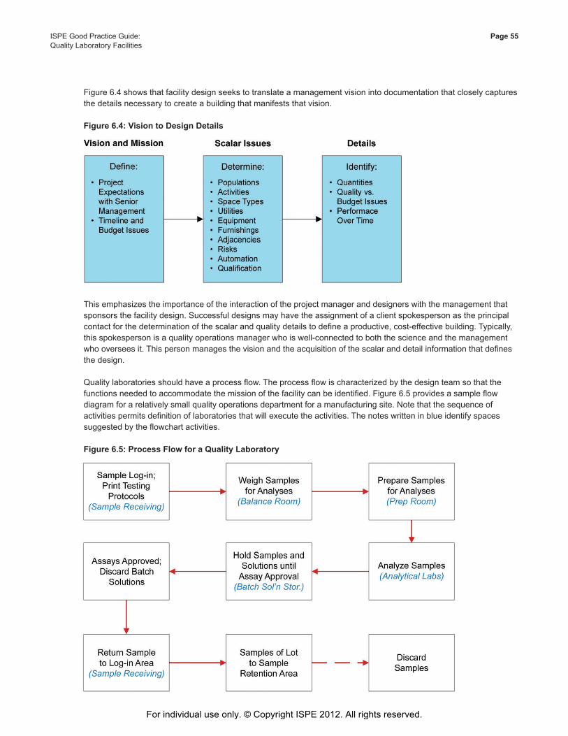
This Document is licensed to
Mr. George FrancisDublin 17,
ID number: 53416
Downloaded on: 4/2/13 4:13 AM
ISPE Good Practice Guide: Page 55Quality Laboratory Facilities
Figure 6.4 shows that facility design seeks to translate a management vision into documentation that closely captures the details necessary to create a building that manifests that vision.
Figure 6.4: Vision to Design Details
This emphasizes the importance of the interaction of the project manager and designers with the management that sponsors the facility design. Successful designs may have the assignment of a client spokesperson as the principal contact for the determination of the scalar and quality details to define a productive, cost-effective building. Typically, this spokesperson is a quality operations manager who is well-connected to both the science and the management who oversees it. This person manages the vision and the acquisition of the scalar and detail information that defines the design.
Quality laboratories should have a process flow. The process flow is characterized by the design team so that the functions needed to accommodate the mission of the facility can be identified. Figure 6.5 provides a sample flow diagram for a relatively small quality operations department for a manufacturing site. Note that the sequence of activities permits definition of laboratories that will execute the activities. The notes written in blue identify spaces suggested by the flowchart activities.
Figure 6.5: Process Flow for a Quality Laboratory
For individual use only. © Copyright ISPE 2012. All rights reserved.
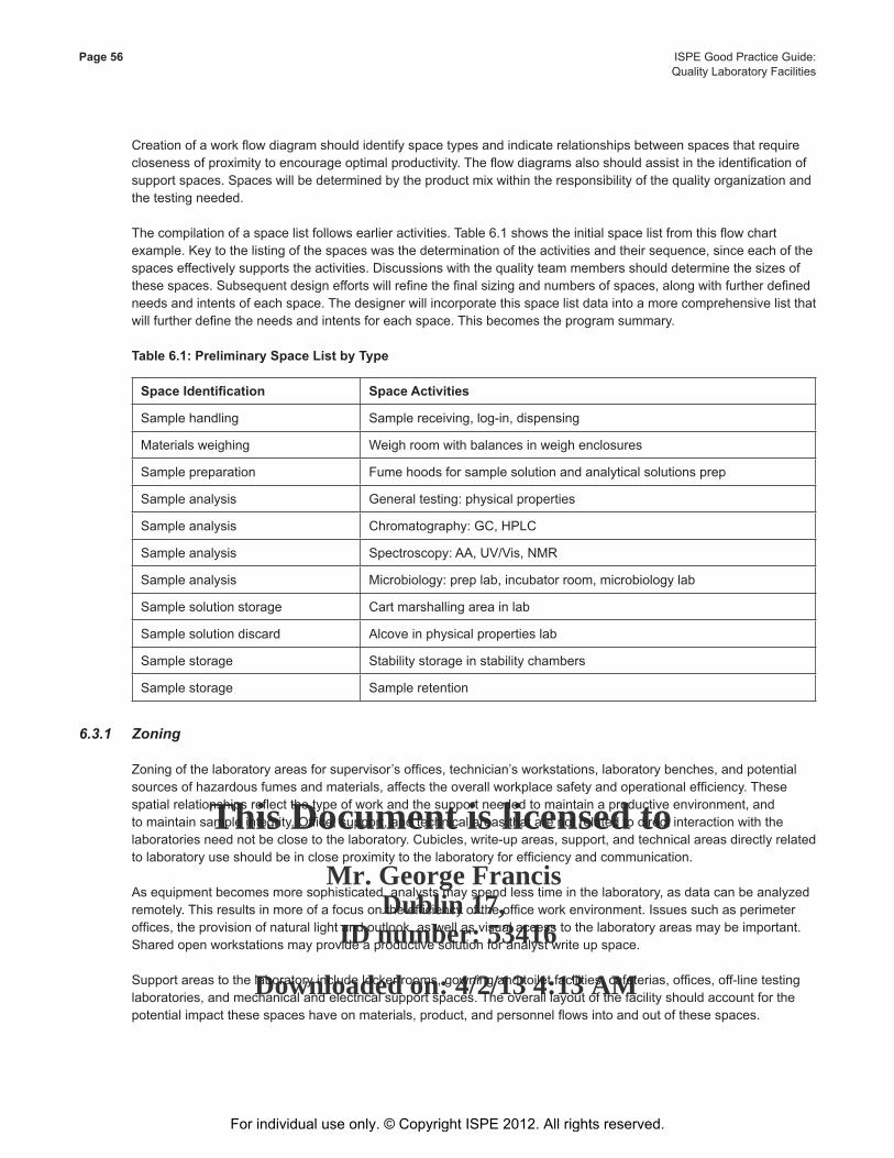
This Document is licensed to
Mr. George FrancisDublin 17,
ID number: 53416
Downloaded on: 4/2/13 4:13 AM
Page 56 ISPE Good Practice Guide: Quality Laboratory Facilities
Creation of a work flow diagram should identify space types and indicate relationships between spaces that require closeness of proximity to encourage optimal productivity. The flow diagrams also should assist in the identification of support spaces. Spaces will be determined by the product mix within the responsibility of the quality organization and the testing needed.
The compilation of a space list follows earlier activities. Table 6.1 shows the initial space list from this flow chart example. Key to the listing of the spaces was the determination of the activities and their sequence, since each of the spaces effectively supports the activities. Discussions with the quality team members should determine the sizes of these spaces. Subsequent design efforts will refine the final sizing and numbers of spaces, along with further defined needs and intents of each space. The designer will incorporate this space list data into a more comprehensive list that will further define the needs and intents for each space. This becomes the program summary.
Table 6.1: Preliminary Space List by Type
Space Identification Space Activities
Sample handling Sample receiving, log-in, dispensing
Materials weighing Weigh room with balances in weigh enclosures
Sample preparation Fume hoods for sample solution and analytical solutions prep
Sample analysis General testing: physical properties
Sample analysis Chromatography: GC, HPLC
Sample analysis Spectroscopy: AA, UV/Vis, NMR
Sample analysis Microbiology: prep lab, incubator room, microbiology lab
Sample solution storage Cart marshalling area in lab
Sample solution discard Alcove in physical properties lab
Sample storage Stability storage in stability chambers
Sample storage Sample retention
6.3.1 Zoning
Zoning of the laboratory areas for supervisor’s offices, technician’s workstations, laboratory benches, and potential sources of hazardous fumes and materials, affects the overall workplace safety and operational efficiency. These spatial relationships reflect the type of work and the support needed to maintain a productive environment, and to maintain sample integrity. Office, support, and technical areas that are not related to direct interaction with the laboratories need not be close to the laboratory. Cubicles, write-up areas, support, and technical areas directly related to laboratory use should be in close proximity to the laboratory for efficiency and communication.
As equipment becomes more sophisticated, analysts may spend less time in the laboratory, as data can be analyzed remotely. This results in more of a focus on the efficiency of the office work environment. Issues such as perimeter offices, the provision of natural light and outlook, as well as visual access to the laboratory areas may be important. Shared open workstations may provide a productive solution for analyst write up space.
Support areas to the laboratory include locker rooms, gowning and toilet facilities, cafeterias, offices, off-line testing laboratories, and mechanical and electrical support spaces. The overall layout of the facility should account for the potential impact these spaces have on materials, product, and personnel flows into and out of these spaces.
For individual use only. © Copyright ISPE 2012. All rights reserved.
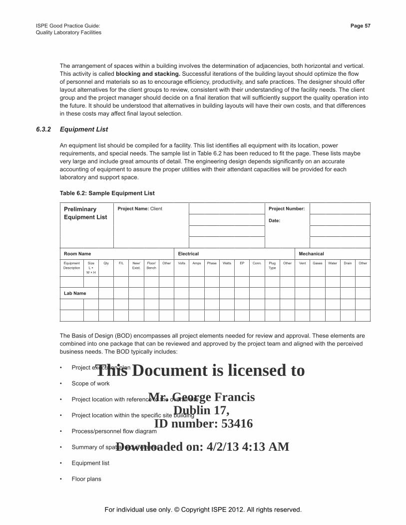
This Document is licensed to
Mr. George FrancisDublin 17,
ID number: 53416
Downloaded on: 4/2/13 4:13 AM
ISPE Good Practice Guide: Page 57Quality Laboratory Facilities
The arrangement of spaces within a building involves the determination of adjacencies, both horizontal and vertical. This activity is called blocking and stacking. Successful iterations of the building layout should optimize the flow of personnel and materials so as to encourage efficiency, productivity, and safe practices. The designer should offer layout alternatives for the client groups to review, consistent with their understanding of the facility needs. The client group and the project manager should decide on a final iteration that will sufficiently support the quality operation into the future. It should be understood that alternatives in building layouts will have their own costs, and that differences in these costs may affect final layout selection.
6.3.2 Equipment List
An equipment list should be compiled for a facility. This list identifies all equipment with its location, power requirements, and special needs. The sample list in Table 6.2 has been reduced to fit the page. These lists maybe very large and include great amounts of detail. The engineering design depends significantly on an accurate accounting of equipment to assure the proper utilities with their attendant capacities will be provided for each laboratory and support space.
Table 6.2: Sample Equipment List
Preliminary Equipment List
Project Name: Client Project Number:
Date:
Room Name Electrical Mechanical
Equipment Description
SizeL ×
W × H
Qty F/L New/Exist.
Floor/Bench
Other Volts Amps Phase Watts EP Conn. Plug Type
Other Vent Gases Water Drain Other
Lab Name
The Basis of Design (BOD) encompasses all project elements needed for review and approval. These elements are combined into one package that can be reviewed and approved by the project team and aligned with the perceived business needs. The BOD typically includes:
• Project execution plan
• Scope of work
• Project location with reference to the overall site
• Project location within the specific site building
• Process/personnel flow diagram
• Summary of spatial requirements
• Equipment list
• Floor plans
For individual use only. © Copyright ISPE 2012. All rights reserved.
This Document is licensed to
Mr. George FrancisDublin 17,
ID number: 53416
Downloaded on: 4/2/13 4:13 AM
Page 58 ISPE Good Practice Guide: Quality Laboratory Facilities
• Schedule
• Order of magnitude cost estimate
• Building code analysis
• Environmental impact
• Risk analysis
• Construction execution and operational interference plan The preliminary cost estimate included within the BOD usually is the first iteration for the project. It fosters the
first cost/benefit exercise for management. The preliminary estimate may require a reassessment of the facility requirements and a revisiting of the space list.
6.4 Design Development
The BOD documentation should be the agreed-upon scope for the facility. It is at this point that the footprint and layout of the building should have been ascertained and the general sense (i.e., building capacity, quality levels, amenities, etc.) of the intended design understood. The scope and its budget estimate should be reviewed by client management and agreement reached, or alternately, the project scope should be modified to accommodate the project budget. This is a major milestone from which design development begins the official documentation phase of a project.
Design development involves:
• Compiling the architectural detailing for all spaces, both inside and outside of the building
• Determining laboratory casework layout and equipment locations within the laboratories
• Defining quantities and locations of all laboratory utilities
• Determining utility routing inside and outside the facility and the utility capacities
These activities should be performed in an iterative manner, with increasing refinement, until construction documents are complete.
Construction funding may be sought during the design-development phase. With increased definition as the design evolves, increasingly greater accuracy may be expected from the project cost estimate.
It should be emphasized that communication with the client group continues throughout the project design via ongoing project team meetings. Client representatives should review each design iteration with representatives from quality operations.
6.5 Construction
During construction, project meetings typically should be held weekly or biweekly at the construction site. The quality operations representative also should attend these sessions. This will allow the client and the quality department represented to maintain connection with the facility. In addition, it is important that quality operations representatives visit the construction site regularly to understand the evolving translation of the written design to a physical structure. While architects and engineers have the ability to imagine the built facility from drawings, quality operations management, and staff likely will not. Use of 3D now allows users to see the design at early stages.
For individual use only. © Copyright ISPE 2012. All rights reserved.
This Document is licensed to
Mr. George FrancisDublin 17,
ID number: 53416
Downloaded on: 4/2/13 4:13 AM
ISPE Good Practice Guide: Page 59Quality Laboratory Facilities
6.6 Commissioning and Qualification
Commissioning quality laboratory facilities begins at the programming stage. This is the time when the extent of the impact of relevant GMP regulations and company standards are defined for the facility. The subsequent design accommodates the necessary controls and area definitions such that the intent of the regulations are embraced and achieved. Attention to fulfilling the regulatory requirements continues through design, construction, and commissioning. When the facility is turned over to the client, the building systems will be working as intended.
6.7 Budgeting
Construction costs can vary greatly. Examples of this can be seen when comparing the average cost of a fume hood intensive chemistry laboratory to a biology laboratory or a very complicated, process intensive, CGMP pilot plant laboratory that is designed to handle potent compounds. Each of these laboratories fall under the heading of “laboratory building,” but the finishes, infrastructure, and support systems are very different and have a different impact on the overall facility cost. While this section deals with cost, the owner, design professional, and the constructor should ensure that safety, both during construction and within the new laboratory, is the primary concern.
The development of a project budget for a laboratory facility should be done by an experienced organization. The development of a baseline budget or estimate of a new laboratory facility varies greatly with the type and use of the facility. This is not the case when building other types of facilities where there is little variation in the type of materials or design. A good case in point would be an office building where a reliable order of magnitude can usually be obtained by applying a cost-per-square-foot standard or by comparing similar facilities.
Although laboratories may seem extremely similar, each is unique. Each laboratory has:
• Specific expectations from users regarding programming, finish quality, amenities, and projected longevity
• Different demands for mechanical and process systems • Issues that will impact site development and construction costs
These variables (and others to be discussed in more detail) can significantly affect the construction and project costs.
6.7.1 Budget Components
The cost of a laboratory facility is typically detailed and arranged by Construction Specification Institute (CSI) codes. They usually include the cost for the actual construction (bricks and mortar) plus a number of other costs, including:
• Land acquisition
• Planning and feasibility studies
• Architectural and engineering design fees
• Specialist consultants (sound, environmental, traffic, etc.)
• Permits and legal fees
• Construction, including materials, equipment and labor
• Field supervision of construction
• General conditions and requirements
For individual use only. © Copyright ISPE 2012. All rights reserved.
This Document is licensed to
Mr. George FrancisDublin 17,
ID number: 53416
Downloaded on: 4/2/13 4:13 AM
Page 60 ISPE Good Practice Guide: Quality Laboratory Facilities
• Insurance and taxes
• Owner’s general office overhead
• Furniture, Fixtures, and Equipment (FF&E) not included in construction
• Inspection and testing
• Start-up, commissioning, and qualification
• Moving costs
• Audio visual, data, and telecommunications
• Contingency
In addition, design activities also would include an estimation of operating costs. Operating costs over the project life cycle include:
• Rent, if applicable
• Operating staff
• Laboratory equipment and supplies
• Labor and materials for repairs and changes for adjustments after start-up
• Labor and materials for maintenance and repairs
• Periodic renovations
• Insurance and taxes
• Financing costs
• Utilities
• Owner’s other expenses
The magnitude of each of these cost components depends on the nature, size, and location of the project as well as the management organization, among many considerations. In general, an owner is interested in achieving the lowest possible overall project cost that is consistent with its business objectives.
It is important for design professionals and construction managers to realize that while the construction cost may be the single largest component of the capital cost, other cost components are not insignificant. Life cycle analyses are typically conducted to assist owners in making good decisions.
In most construction budgets, there is an allowance for contingencies or unexpected costs that may arise during construction. This contingency amount may be included within each cost item or be included in a single category of construction contingency. The amount of contingency applied to a particular project is based on several factors, including:
• Historical data and experience with the type of project
For individual use only. © Copyright ISPE 2012. All rights reserved.
This Document is licensed to
Mr. George FrancisDublin 17,
ID number: 53416
Downloaded on: 4/2/13 4:13 AM
ISPE Good Practice Guide: Page 61Quality Laboratory Facilities
• Phase of the project and level of completeness of the design drawings
• Anticipated changes
• Schedule pressures
• Site conditions, including costs due to local ordinances pertaining to zoning, etc.
6.7.2 Influences
The influences that can have an impact on the construction costs of a laboratory facility can be grouped into three categories:
1. External
2. Internal
3. Project approach
External influences are those that the facility owner or designer will not have control over. These influences will vary from location to location and year to year and include:
• Local market conditions – these are usually driven by the specific dynamics of supply and demand and the labor force in the area where the construction is proposed.
• Material Costs – energy prices may remain elevated, making the energy-intensive process for making steel more expensive. In addition to higher energy costs, there is a growing global demand for steel and raw materials that has elevated market prices.
• Energy Cost – operations and transportation.
• The value of currency – As the local currency drops against other currencies, imports will become costlier.
• Regulatory changes – continued pressure from outside regulatory agencies to look at laboratory operations.
• Local Authority Having Jurisdiction (AHJ) regarding construction
The facility operator or designer has some control over internal influences. These influences will vary from project to project as a result of the type and application of the laboratory, the type of materials that are being handled and the amount of flexibility that the end user needs. These influences include:
• The facility program – the type and number of laboratories, the blocking and stacking of like functions in the building
• The number of fume hoods in the laboratory
• Flexibility of utilities in each laboratory
• Classification of laboratories for the handling of hazardous materials, i.e., Biosafety Level 2 (BSL-2), Biosafety Level 3 (BSL-3), and Potent Compounds
• The level of finishes needed
• Classifications of laboratories for cleanroom applications
For individual use only. © Copyright ISPE 2012. All rights reserved.
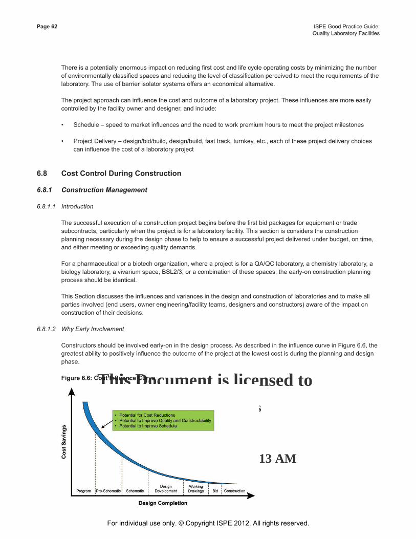
This Document is licensed to
Mr. George FrancisDublin 17,
ID number: 53416
Downloaded on: 4/2/13 4:13 AM
Page 62 ISPE Good Practice Guide: Quality Laboratory Facilities
There is a potentially enormous impact on reducing first cost and life cycle operating costs by minimizing the number of environmentally classified spaces and reducing the level of classification perceived to meet the requirements of the laboratory. The use of barrier isolator systems offers an economical alternative.
The project approach can influence the cost and outcome of a laboratory project. These influences are more easily controlled by the facility owner and designer, and include:
• Schedule – speed to market influences and the need to work premium hours to meet the project milestones
• Project Delivery – design/bid/build, design/build, fast track, turnkey, etc., each of these project delivery choices can influence the cost of a laboratory project
6.8 Cost Control During Construction
6.8.1 Construction Management
6.8.1.1 Introduction
The successful execution of a construction project begins before the first bid packages for equipment or trade subcontracts, particularly when the project is for a laboratory facility. This section is considers the construction planning necessary during the design phase to help to ensure a successful project delivered under budget, on time, and either meeting or exceeding quality demands.
For a pharmaceutical or a biotech organization, where a project is for a QA/QC laboratory, a chemistry laboratory, a biology laboratory, a vivarium space, BSL2/3, or a combination of these spaces; the early-on construction planning process should be identical.
This Section discusses the influences and variances in the design and construction of laboratories and to make all parties involved (end users, owner engineering/facility teams, designers and constructors) aware of the impact on construction of their decisions.
6.8.1.2 Why Early Involvement
Constructors should be involved early-on in the design process. As described in the influence curve in Figure 6.6, the greatest ability to positively influence the outcome of the project at the lowest cost is during the planning and design phase.
Figure 6.6: Cost Influence Curve
For individual use only. © Copyright ISPE 2012. All rights reserved.
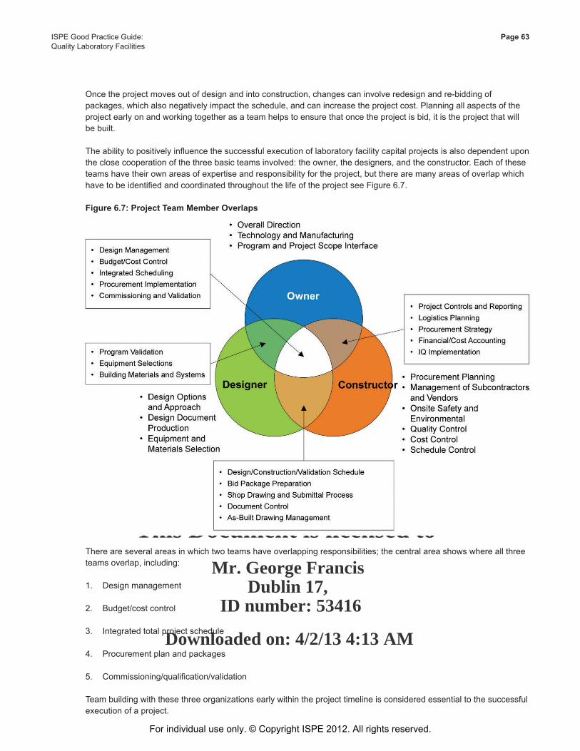
This Document is licensed to
Mr. George FrancisDublin 17,
ID number: 53416
Downloaded on: 4/2/13 4:13 AM
ISPE Good Practice Guide: Page 63Quality Laboratory Facilities
Once the project moves out of design and into construction, changes can involve redesign and re-bidding of packages, which also negatively impact the schedule, and can increase the project cost. Planning all aspects of the project early on and working together as a team helps to ensure that once the project is bid, it is the project that will be built.
The ability to positively influence the successful execution of laboratory facility capital projects is also dependent upon the close cooperation of the three basic teams involved: the owner, the designers, and the constructor. Each of these teams have their own areas of expertise and responsibility for the project, but there are many areas of overlap which have to be identified and coordinated throughout the life of the project see Figure 6.7.
Figure 6.7: Project Team Member Overlaps
There are several areas in which two teams have overlapping responsibilities; the central area shows where all three teams overlap, including:
1. Design management
2. Budget/cost control
3. Integrated total project schedule
4. Procurement plan and packages
5. Commissioning/qualification/validation
Team building with these three organizations early within the project timeline is considered essential to the successful execution of a project.
For individual use only. © Copyright ISPE 2012. All rights reserved.
This Document is licensed to
Mr. George FrancisDublin 17,
ID number: 53416
Downloaded on: 4/2/13 4:13 AM
Page 64 ISPE Good Practice Guide: Quality Laboratory Facilities
6.8.1.3 Total Integrated Project Schedule
A capital project involves more than the typical design and construction schedules. The project schedule should incorporate all components of the project in order to give a true picture of the status of the project. Critical path items tend to differ from project to project and from phase to phase within the project, but decisions and actions made during the life of the project have implications on other components. The schedule is largely driven by the date when the quality organization needs to begin work in the laboratory space.
By developing a total integrated project schedule during the planning and early design phase, critical paths can be identified and strategies developed to address these. Among the important early milestones should be internal funding dates and local and agency permitting dates, which have a direct influence on deliverables due from the designer and contractor.
Once the project begins, design deliverable dates should be reflective of the procurement strategy the team has agreed upon:
• The bidding schedules of equipment and trades should reflect the execution strategy of the team, as does the construction schedule with its dozens and dozens of sub-schedules.
• The commissioning and qualification schedule and sub-schedules should reflect the strategy needed to meet regulatory needs.
• The move-in schedule reflects how the end users will inhabit the facility to facilitate their research efforts.
These may be interdependent upon each other, a change in procurement that will have an effect on the commissioning and subsequently the move-in will be accurately reflected, allowing the team to develop the right strategies to bring the end date back in line.
6.8.1.4 Start-Up,Commissioning,andQualification
The commissioning and qualification of a laboratory facility is critically important. During design and construction, the quality lead, regulatory compliance, facilities representatives, and project lead collaboratively work to assure that the laboratory facility will be commissioned and qualified efficiently with the least re-work. This can only be accomplished when properly planned, designed, procured, and installed to ensure compliance.
With this in mind, the planning should incorporate the following:
• Commissioning should be integrated into the design deliverable packages, the procurement/bid packages with all of the inspection and “paperwork” requirements, and the construction schedules.
• Within the master schedule, a very detailed sub-schedule calls out all of the start-up, commissioning, and qualifications efforts needed with special emphasis places on critical path requirements.
• Secure an agreed upon commitment from the vendor with regard to their internal fabrication schedule to assure that the availability of the equipment will be on time and that they have a plan and the resource in place meet the Factory Acceptance Test (FAT) schedule.
• Develop an FAT and Site Acceptance Test (SAT) strategy that includes who is responsible for what, which members of the team will perform which inspections, and what is each team member specifically responsible for on the inspections. The level of quality needed would also be included.
• The constructor has to develop and implement procedures to manage a host of activities that have impact on the start-up, commissioning, and qualification efforts to follow, including:
For individual use only. © Copyright ISPE 2012. All rights reserved.
This Document is licensed to
Mr. George FrancisDublin 17,
ID number: 53416
Downloaded on: 4/2/13 4:13 AM
ISPE Good Practice Guide: Page 65Quality Laboratory Facilities
- Quality control
- Punch list execution to support early start-up activities
- System completion focus
- Turn over package development
- System certification requirements
6.8.1.5 Safety
When designing and building any laboratory facility, safety is the primary concern – for the end users, for others on the campus, and for personnel constructing the facility. Safety requirements for the quality staff should be incorporated into the design documents, and safety requirements for the trades should be built into the construction bid packages, and reinforced throughout the construction.
Primary tools for this are the logistics plan(s) and the Hazards of Construction Risk Assessment (HAZCON) developed to accurately reflect how the project will be executed. The safe and efficient movement of personnel, materials, and equipment is considered fundamental, and can change with the phase of the project. These plans should be included in the bid packages so that the trades know what is expected of them for parking, laydown, delivery schedules, etc. These are developed in conjunction with the site security and safety teams to ensure that personnel follow the appropriate protocols.
6.8.1.6 Procurement Strategy
As the team develops the execution strategy for the project, the procurement strategy should begin development. Working closely with the design team, the appropriate quantity of design packages should be developed with the schedule as to when they are needed to bid so as to meet the construction schedule. The goal of the procurement strategy is relatively simple: manage risk through the right procurement plan. This is achieved by procuring the following from the most qualified contractors:
• Schedule commitment
• Logistics/security plan
• Safety and environmental program
• FAT, SAT and systems start-up requirements and training for operators
• Commissioning/qualification/documentation support
• Cost mdel/control
• Contract type and terms
The aim is to get the best value for the investment allocated, and the procurement strategy should emphasize this.
6.8.1.7 Value Management/Constructability
Value Management (VM) (also known as value engineering) and constructability efforts are lost when performed after the project is bid in order to bring the project back to budget. VM is valuable when performed early on and continuously during the planning and schematic phases, because the emphasis there is on systems, which is where the real values are found. As the team goes through the design review meetings, ideally the areas of discussion should center around:
For individual use only. © Copyright ISPE 2012. All rights reserved.
This Document is licensed to
Mr. George FrancisDublin 17,
ID number: 53416
Downloaded on: 4/2/13 4:13 AM
Page 66 ISPE Good Practice Guide: Quality Laboratory Facilities
• Air distribution/exhaust methods
• Structural system selection
• Mechanical system diversity
• Systems redundancy
• Solid/liquid waste disposal
• Emergency power requirements
• Serviceability/flexibility
• Floor/wall material finishes
• Decontamination methods
• Concrete mix and placement methods (for BSL3/4 facilities)
• Ease of maintenance and repair
VM/constructability meetings are great opportunities to bring the team even closer together. They should include end-users, engineering/facility staff, maintenance staff, designers, and constructors, and may include specialty trades where appropriate. The meetings should identify, confront, and resolve design issues, and reduce re-work. They should provide the team with options and alternatives to be reviewed early on when an elimination of a wall or HVAC line involves erasing a line on paper. They should include specific deliverables, whether an action plan, benchmark information, estimate or schedule impact or whatever. This provides information for the team to make informed decisions that will positively impact the project.
6.8.1.8 Planning Deliverables
Deliverables provided at the end of pre-construction include:
• Constructability reviews
• Value engineering reviews
• Conceptual cost analysis report
• Conceptual schedule analysis report
• Integrated project execution plan
• Integrated project procedures manual
• Site logistics plan
• Clean build plan
• Prefabrication strategy and plan
• Construction sequencing plan
For individual use only. © Copyright ISPE 2012. All rights reserved.
This Document is licensed to
Mr. George FrancisDublin 17,
ID number: 53416
Downloaded on: 4/2/13 4:13 AM
ISPE Good Practice Guide: Page 67Quality Laboratory Facilities
• Construction permitting plan
• Cash flow projections
• Construction cost estimates
• Procurement plan with bid package preparation
• Project schedule
• Site specific environmental, health and safety plan
• Integrated quality assurance plan and construction QA dossier
• Integrated start-up, commissioning, and validation plan
For individual use only. © Copyright ISPE 2012. All rights reserved.

This Document is licensed to
Mr. George FrancisDublin 17,
ID number: 53416
Downloaded on: 4/2/13 4:13 AM
For individual use only. © Copyright ISPE 2012. All rights reserved.
This Document is licensed to
Mr. George FrancisDublin 17,
ID number: 53416
Downloaded on: 4/2/13 4:13 AM
ISPE Good Practice Guide: Page 69Quality Laboratory Facilities
7 Architectural7.1 Introduction
This Chapter provides project architectural concepts for consideration when designing a laboratory facility that supports the quality functions of products being manufactured and distributed for human consumption. The concepts presented are global in nature and do not take into consideration local code issues or organizational cultural considerations.
The primary architectural goals are:
• Todesignandconstructafacilitythatmeetsallrequirementsforaqualitytestinglaboratory
• Tocomplywithalllocalcodes,zoningordinances,andFederalregulations(disabilityandapplicableGMPregulations)
• Toincorporatecommissioningandqualificationrequirements(whereneeded)intothebuildingdesign
• Toselectappropriatebuildingmaterials
• Toconsiderdesignprovisionsforfutureexpansionofthelaboratory
• Todevelopanagreed-uponprojectscheduleandbudgetrange
• Toalignwithcorporatestandards/expectations
7.1.1 Laboratories in the Scope of This Guide
Laboratories supporting the manufacturing of regulated compounds as well as their process development and improvement are many and varied. This Chapter discusses design considerations for each type of quality laboratory as well as issues and concerns that apply to all laboratories. This discussion will focus on the following areas:
• Incomingmaterialinspectionandtestinglaboratories
• In-processandoff-lineintermediatetestinglaboratories
• Finalreleaseandstabilitytestinglaboratories
• Samplestorageandrecordsretentionareas
• Othersupportareassuchassolventstorage,materialsstorage,wastehandling
7.1.2 Intended Use
This Chapter of the Guide is intended to assist and guide a user in the conduct of the laboratory design process as wellastheprocessofmakingdecisionsinarchitecturallayouts,finishes,adjacencies,andothercomponentsofthedesignfornewandrenovatedlaboratories.Benefitsanddrawbacksofvariousoptionsarereviewedtoallowtheusertomakethemostappropriatedetermination,selection,anddecisionfortheirparticularsituation.
This Chapter is intended to provide information which may be used as a basis for making decisions.
For individual use only. © Copyright ISPE 2012. All rights reserved.
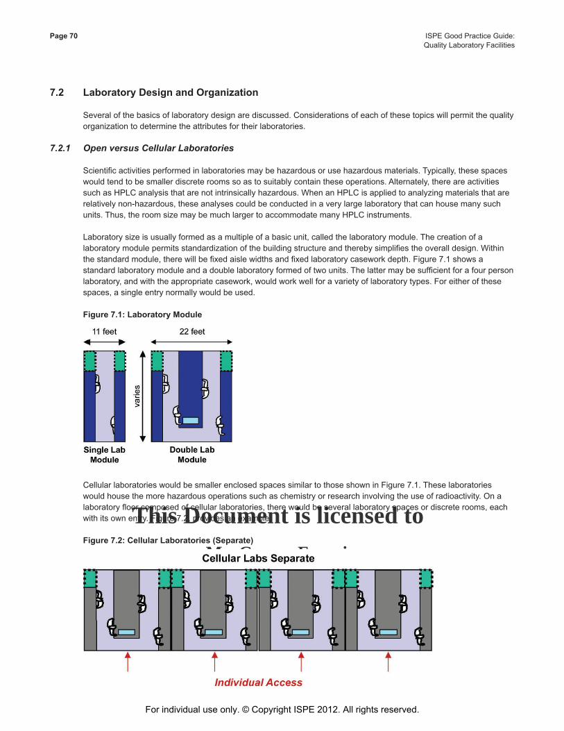
This Document is licensed to
Mr. George FrancisDublin 17,
ID number: 53416
Downloaded on: 4/2/13 4:13 AM
Page 70 ISPE Good Practice Guide: Quality Laboratory Facilities
7.2 Laboratory Design and Organization
Several of the basics of laboratory design are discussed. Considerations of each of these topics will permit the quality organization to determine the attributes for their laboratories.
7.2.1 Open versus Cellular Laboratories
Scientificactivitiesperformedinlaboratoriesmaybehazardousorusehazardousmaterials.Typically,thesespaceswouldtendtobesmallerdiscreteroomssoastosuitablycontaintheseoperations.Alternately,thereareactivitiessuch as HPLC analysis that are not intrinsically hazardous. When an HPLC is applied to analyzing materials that are relativelynon-hazardous,theseanalysescouldbeconductedinaverylargelaboratorythatcanhousemanysuchunits.Thus,theroomsizemaybemuchlargertoaccommodatemanyHPLCinstruments.
Laboratorysizeisusuallyformedasamultipleofabasicunit,calledthelaboratorymodule.Thecreationofalaboratorymodulepermitsstandardizationofthebuildingstructureandtherebysimplifiestheoveralldesign.Withinthestandardmodule,therewillbefixedaislewidthsandfixedlaboratorycaseworkdepth.Figure7.1showsastandardlaboratorymoduleandadoublelaboratoryformedoftwounits.Thelattermaybesufficientforafourpersonlaboratory,andwiththeappropriatecasework,wouldworkwellforavarietyoflaboratorytypes.Foreitherofthesespaces,asingleentrynormallywouldbeused.
Figure 7.1: Laboratory Module
CellularlaboratorieswouldbesmallerenclosedspacessimilartothoseshowninFigure7.1.Theselaboratorieswouldhousethemorehazardousoperationssuchaschemistryorresearchinvolvingtheuseofradioactivity.Onalaboratoryfloorcomposedofcellularlaboratories,therewouldbeseverallaboratoryspacesordiscreterooms,eachwithitsownentry.Figure7.2,providesanexample.
Figure 7.2: Cellular Laboratories (Separate)
For individual use only. © Copyright ISPE 2012. All rights reserved.
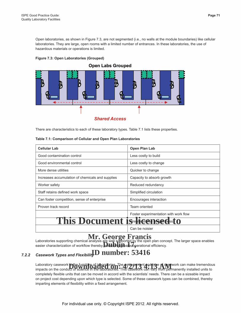
This Document is licensed to
Mr. George FrancisDublin 17,
ID number: 53416
Downloaded on: 4/2/13 4:13 AM
ISPE Good Practice Guide: Page 71Quality Laboratory Facilities
Openlaboratories,asshowninFigure7.3,arenotsegmented(i.e.,nowallsatthemoduleboundaries)likecellularlaboratories.Theyarelarge,openroomswithalimitednumberofentrances.Intheselaboratories,theuseofhazardous materials or operations is limited.
Figure 7.3: Open Laboratories (Grouped)
Therearecharacteristicstoeachoftheselaboratorytypes.Table7.1liststheseproperties.
Table 7.1: Comparison of Cellular and Open Plan Laboratories
Cellular Lab Open Plan Lab
Good contamination control Less costly to build
Good environmental control Less costly to change
Moredenseutilities Quicker to change
Increases accumulation of chemicals and supplies Capacity to absorb growth
Worker safety Reduced redundancy
Staffretainsdefinedworkspace Simplifiedcirculation
Canfostercompetition,senseofenterprise Encourages interaction
Proven track record Team oriented
Fosterexperimentationwithworkflow
Greater sense of openness
Can be noisier
Laboratories supporting chemical analysis are well supported by the open plan concept. The larger space enables easiercharacterizationofworkflowtherebypromotinggreateroperationalefficiency.
7.2.2 Casework Types and Flexibility
Laboratory casework is the furniture of laboratories. The arrangement and type of casework can make tremendous impacts on the conduct of science in the laboratories. This casework can vary from permanently installed units to completelyflexibleunitsthatcanbemovedinaccordwiththescientists’needs.Therecanbeasizeableimpactonprojectcostdependinguponwhichtypeisselected.Someofthesecaseworktypescanbecombined,therebyimpartingelementsofflexibilitywithinafixedarrangement.
For individual use only. © Copyright ISPE 2012. All rights reserved.
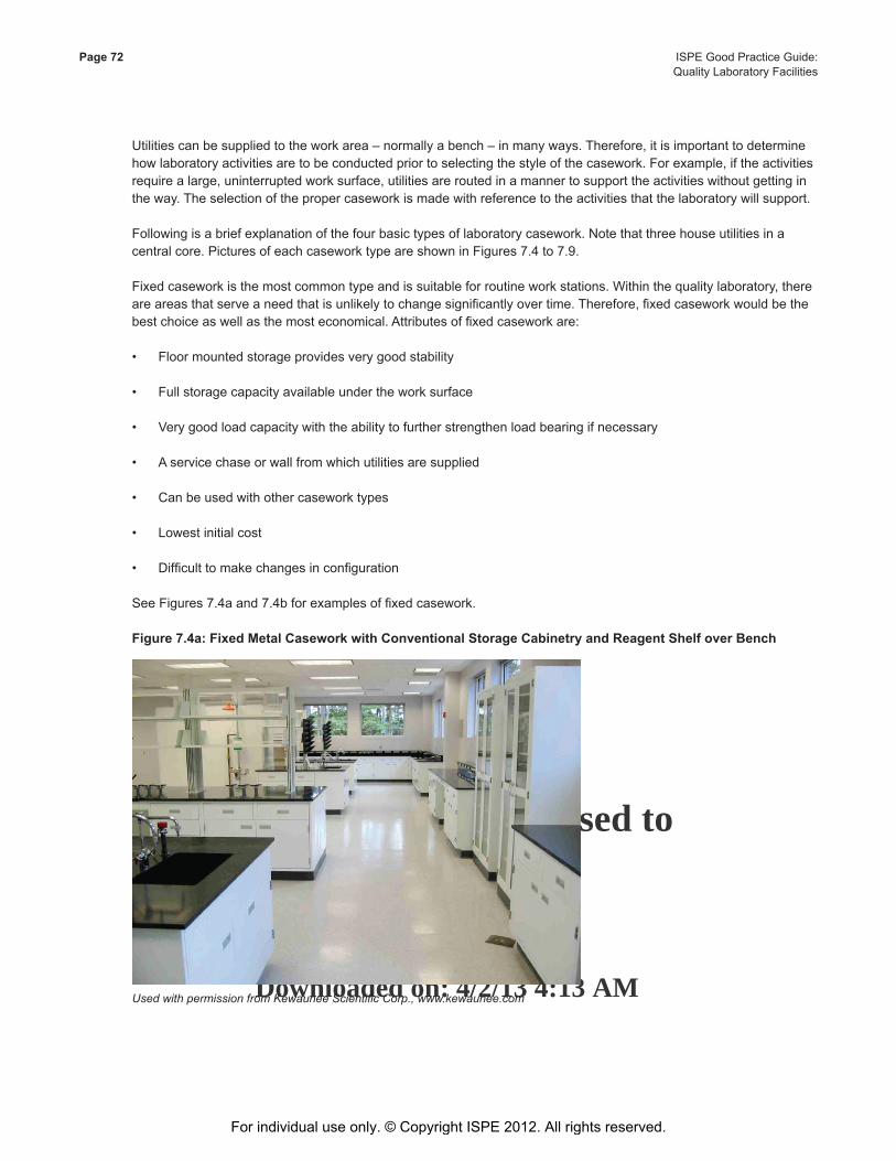
This Document is licensed to
Mr. George FrancisDublin 17,
ID number: 53416
Downloaded on: 4/2/13 4:13 AM
Page 72 ISPE Good Practice Guide: Quality Laboratory Facilities
Utilitiescanbesuppliedtotheworkarea–normallyabench–inmanyways.Therefore,itisimportanttodeterminehowlaboratoryactivitiesaretobeconductedpriortoselectingthestyleofthecasework.Forexample,iftheactivitiesrequirealarge,uninterruptedworksurface,utilitiesareroutedinamannertosupporttheactivitieswithoutgettinginthe way. The selection of the proper casework is made with reference to the activities that the laboratory will support.
Followingisabriefexplanationofthefourbasictypesoflaboratorycasework.Notethatthreehouseutilitiesinacentralcore.PicturesofeachcaseworktypeareshowninFigures7.4to7.9.
Fixedcaseworkisthemostcommontypeandissuitableforroutineworkstations.Withinthequalitylaboratory,thereareareasthatserveaneedthatisunlikelytochangesignificantlyovertime.Therefore,fixedcaseworkwouldbethebestchoiceaswellasthemosteconomical.Attributesoffixedcaseworkare:
• Floormountedstorageprovidesverygoodstability
• Fullstoragecapacityavailableundertheworksurface
• Verygoodloadcapacitywiththeabilitytofurtherstrengthenloadbearingifnecessary
• Aservicechaseorwallfromwhichutilitiesaresupplied
• Canbeusedwithothercaseworktypes
• Lowestinitialcost
• Difficulttomakechangesinconfiguration
SeeFigures7.4aand7.4bforexamplesoffixedcasework.
Figure 7.4a: Fixed Metal Casework with Conventional Storage Cabinetry and Reagent Shelf over Bench
Used with permission from Kewaunee Scientific Corp., www.kewaunee.com
For individual use only. © Copyright ISPE 2012. All rights reserved.
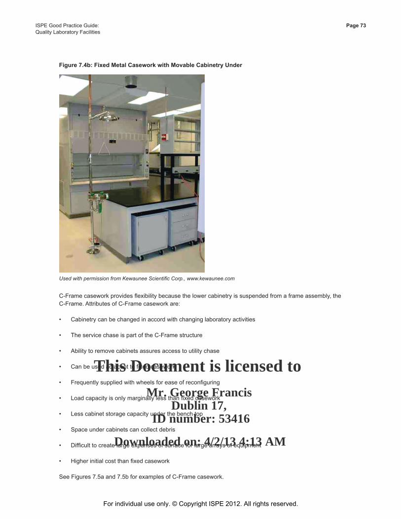
This Document is licensed to
Mr. George FrancisDublin 17,
ID number: 53416
Downloaded on: 4/2/13 4:13 AM
ISPE Good Practice Guide: Page 73Quality Laboratory Facilities
Figure 7.4b: Fixed Metal Casework with Movable Cabinetry Under
Used with permission from Kewaunee Scientific Corp., www.kewaunee.com
C-Framecaseworkprovidesflexibilitybecausethelowercabinetryissuspendedfromaframeassembly,theC-Frame.AttributesofC-Framecaseworkare:
• Cabinetrycanbechangedinaccordwithchanginglaboratoryactivities
• TheservicechaseispartoftheC-Framestructure
• Abilitytoremovecabinetsassuresaccesstoutilitychase
• Canbeusedadjacenttofixedcasework
• Frequentlysuppliedwithwheelsforeaseofreconfiguring
• Loadcapacityisonlymarginallylessthanfixedcasework
• Lesscabinetstoragecapacityunderthebenchtop
• Spaceundercabinetscancollectdebris
• Difficulttocreatelargeexpansesofsurfaceforlargearraysofequipment
• Higherinitialcostthanfixedcasework
SeeFigures7.5aand7.5bforexamplesofC-Framecasework.
For individual use only. © Copyright ISPE 2012. All rights reserved.
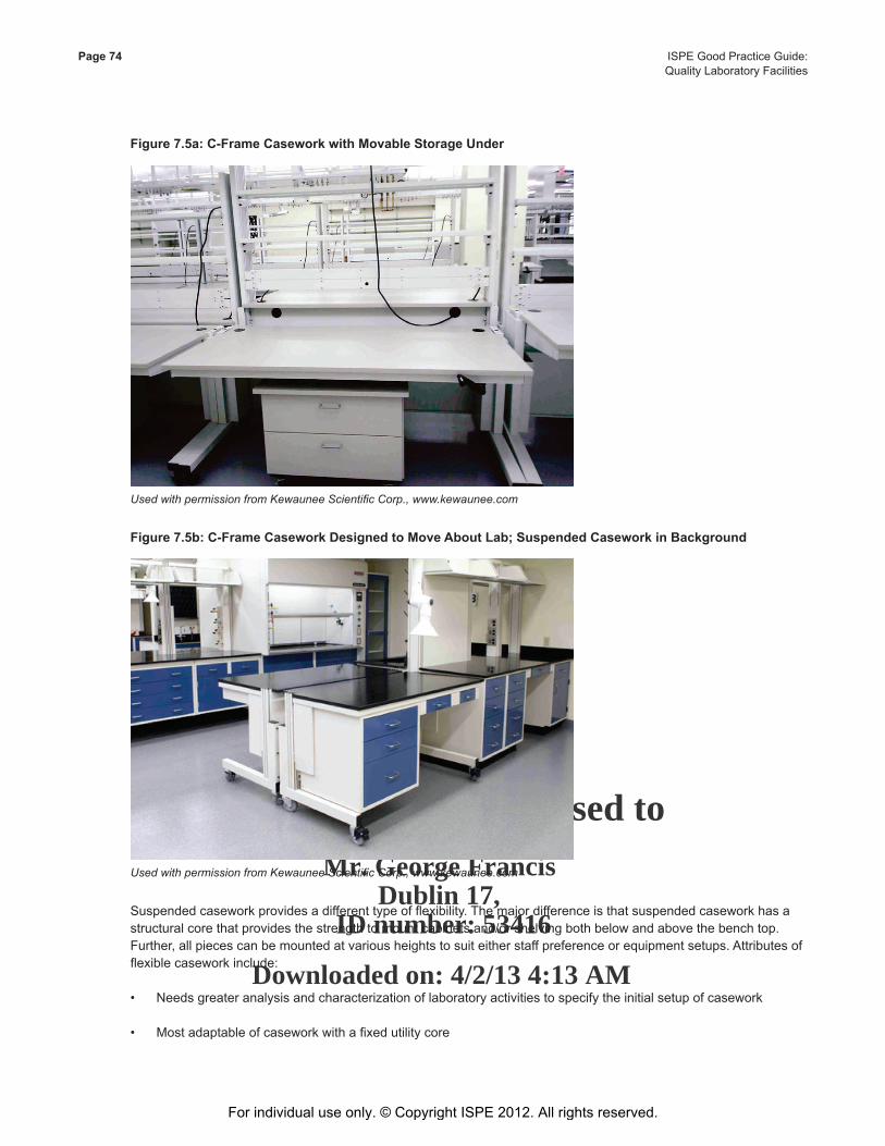
This Document is licensed to
Mr. George FrancisDublin 17,
ID number: 53416
Downloaded on: 4/2/13 4:13 AM
Page 74 ISPE Good Practice Guide: Quality Laboratory Facilities
Figure 7.5a: C-Frame Casework with Movable Storage Under
Used with permission from Kewaunee Scientific Corp., www.kewaunee.com
Figure 7.5b: C-Frame Casework Designed to Move About Lab; Suspended Casework in Background
Used with permission from Kewaunee Scientific Corp., www.kewaunee.com
Suspendedcaseworkprovidesadifferenttypeofflexibility.Themajordifferenceisthatsuspendedcaseworkhasastructuralcorethatprovidesthestrengthtomountcabinetsand/orshelvingbothbelowandabovethebenchtop.Further,allpiecescanbemountedatvariousheightstosuiteitherstaffpreferenceorequipmentsetups.Attributesofflexiblecaseworkinclude:
• Needsgreateranalysisandcharacterizationoflaboratoryactivitiestospecifytheinitialsetupofcasework
• Mostadaptableofcaseworkwithafixedutilitycore
For individual use only. © Copyright ISPE 2012. All rights reserved.

This Document is licensed to
Mr. George FrancisDublin 17,
ID number: 53416
Downloaded on: 4/2/13 4:13 AM
ISPE Good Practice Guide: Page 75Quality Laboratory Facilities
• Componentscanbestoredtoallowchangeoveratanytime
• Mostergonomicallyfriendly
• Canbeusedadjacenttofixedcasework
• Loadcapacityisonlymarginallylessthanfixedcasework
• Lesscabinetstoragecapacityunderbenchtop
• Spaceundercabinetscancollectdebris
• Difficulttocreatelargeexpansesofsurfaceforlargearraysofequipment
• Thestructural/utilitiescorebecomesananchorwithinthelaboratory;thisrestrictsmovementofequipmenttowithin connectivity with this core.
• Higherinitialcostthanfixedcasework
SeeFigures7.6aand7.6bforexamplesofsuspendedcasework.
Figure 7.6a: Suspended Casework with Raised Backsplash and Reagent Shelving
Used with permission from Kewaunee Scientific Corp., www.kewaunee.com
For individual use only. © Copyright ISPE 2012. All rights reserved.
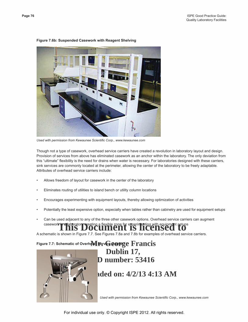
This Document is licensed to
Mr. George FrancisDublin 17,
ID number: 53416
Downloaded on: 4/2/13 4:13 AM
Page 76 ISPE Good Practice Guide: Quality Laboratory Facilities
Figure 7.6b: Suspended Casework with Reagent Shelving
Used with permission from Kewaunee Scientific Corp., www.kewaunee.com
Thoughnotatypeofcasework,overheadservicecarriershavecreatedarevolutioninlaboratorylayoutanddesign.Provision of services from above has eliminated casework as an anchor within the laboratory. The only deviation from this“ultimate”flexibilityistheneedfordrainswhenwaterisnecessary.Forlaboratoriesdesignedwiththesecarriers,sinkservicesarecommonlylocatedattheperimeter,allowingthecenterofthelaboratorytobefreelyadaptable.Attributes of overhead service carriers include:
• Allowsfreedomoflayoutforcaseworkinthecenterofthelaboratory
• Eliminatesroutingofutilitiestoislandbenchorutilitycolumnlocations
• Encouragesexperimentingwithequipmentlayouts,therebyallowingoptimizationofactivities
• Potentiallytheleastexpensiveoption,especiallywhentablesratherthancabinetryareusedforequipmentsetups
• Canbeusedadjacenttoanyofthethreeothercaseworkoptions.Overheadservicecarrierscanaugmentcaseworkinalaboratorycreatingaflexiblezoneforexperimentingwithequipmentsetups
AschematicisshowninFigure7.7.SeeFigures7.8aand7.8bforexamplesofoverheadservicecarriers.
Figure 7.7: Schematic of Overhead Service Carrier
Used with permission from Kewaunee Scientific Corp., www.kewaunee.com
For individual use only. © Copyright ISPE 2012. All rights reserved.
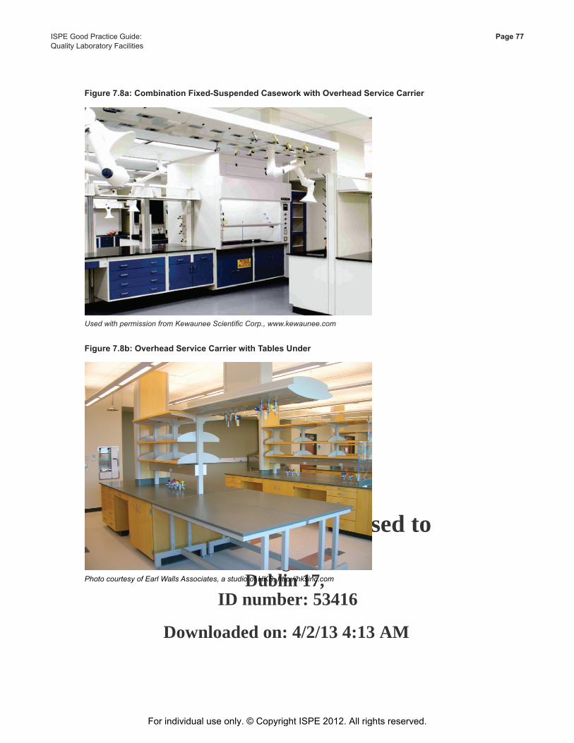
This Document is licensed to
Mr. George FrancisDublin 17,
ID number: 53416
Downloaded on: 4/2/13 4:13 AM
ISPE Good Practice Guide: Page 77Quality Laboratory Facilities
Figure 7.8a: Combination Fixed-Suspended Casework with Overhead Service Carrier
Used with permission from Kewaunee Scientific Corp., www.kewaunee.com
Figure 7.8b: Overhead Service Carrier with Tables Under
Photo courtesy of Earl Walls Associates, a studio of HKS, http://hksinc.com
For individual use only. © Copyright ISPE 2012. All rights reserved.
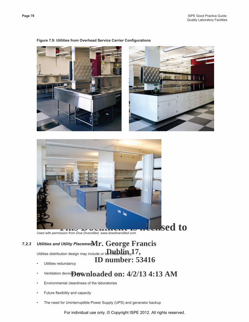
This Document is licensed to
Mr. George FrancisDublin 17,
ID number: 53416
Downloaded on: 4/2/13 4:13 AM
Page 78 ISPE Good Practice Guide: Quality Laboratory Facilities
Figure7.9:UtilitiesfromOverheadServiceCarrierConfigurations
Used with permission from Dow Diversified, www.dowdiversified.com
7.2.3 Utilities and Utility Placement
Utilitiesdistributiondesignmayincludeorbeinfluencedby:
• Utilitiesredundancy
• Ventilationdevicesused
• Environmentalcleanlinessofthelaboratories
• Futureflexibilityandcapacity
• TheneedforUninterruptiblePowerSupply(UPS)andgeneratorbackup
For individual use only. © Copyright ISPE 2012. All rights reserved.
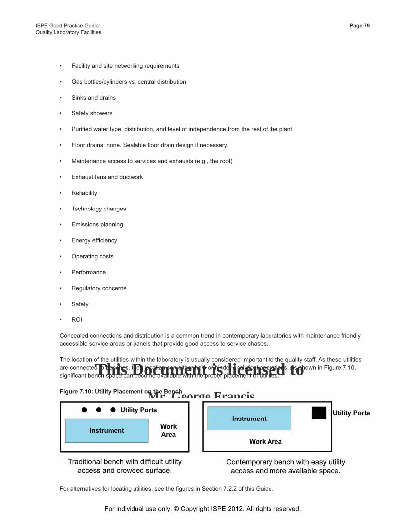
This Document is licensed to
Mr. George FrancisDublin 17,
ID number: 53416
Downloaded on: 4/2/13 4:13 AM
ISPE Good Practice Guide: Page 79Quality Laboratory Facilities
• Facilityandsitenetworkingrequirements
• Gasbottles/cylindersvs.centraldistribution
• Sinksanddrains
• Safetyshowers
• Purifiedwatertype,distribution,andlevelofindependencefromtherestoftheplant
• Floordrains:none.Sealablefloordraindesignifnecessary.
• Maintenanceaccesstoservicesandexhausts(e.g.,theroof)
• Exhaustfansandductwork
• Reliability
• Technologychanges
• Emissionsplanning
• Energyefficiency
• Operatingcosts
• Performance
• Regulatoryconcerns
• Safety
• ROI
Concealed connections and distribution is a common trend in contemporary laboratories with maintenance friendly accessible service areas or panels that provide good access to service chases.
The location of the utilities within the laboratory is usually considered important to the quality staff. As these utilities areconnectedtobenches,theirlocationcaneitherhelporhinderanalyticaloperations.AsshowninFigure7.10,significantbenchspacecanbecomeavailablewiththeproperplacementofutilities.
Figure 7.10: Utility Placement on the Bench
Foralternativesforlocatingutilities,seethefiguresinSection7.2.2ofthisGuide.
For individual use only. © Copyright ISPE 2012. All rights reserved.
This Document is licensed to
Mr. George FrancisDublin 17,
ID number: 53416
Downloaded on: 4/2/13 4:13 AM
Page 80 ISPE Good Practice Guide: Quality Laboratory Facilities
7.2.4 Materials Storage and Handling
Materialsstorageisasignificantissueinlaboratorydesign.Regulationstightlylimitsolventquantitiesandhandling,whichfrequentlybecomesacontrollingissueinthenumberandlocationsofstoragespacesinafacility.However,othertypesofsubstancesmayescapethescrutinythatsolventstoragereceives.Designersshouldbeproactiveabout providing space for proper storage of materials. Following are guidelines offered for storage of various substances in or near the laboratory:
• Solvents:storeunderhoodorinsolventstoragecabinets;organicvaporsareheavierthanair;therefore,provideexhaustatfloorlevelifventingismandated.
• Oxidizers:storeinaseparatecabinet;notethatthesearenotnormallyusedinsignificantquantities.
• Acids:typicallystoredunderthefumehood.
• Reactivegases:storedoutsideinventilatedarea.In-usecylindersmaybeplacedincylinderstoragecabinetsinornearthelaboratoryandfedtothelaboratoryusepoint(s).Mostgasesareheavierthanair.Storageareasshouldbeventedatbothfloorandceilinglevels.
• Hydrogen:Alwaysstoredandusedinadraftedarea,ventedatceilinglevel.Hydrogenisexplosiveinairfromfourto75%byvolume,makingitapotentexplosionhazard.Fugitiveemissionsshouldbescrupulouslyremoved.DetaileddesignrecommendationscanbeobtainedfromtheNationalSafetyCouncilaswellasfromtheNationalFire Protection Association and other agencies.
• Othergases:storecylindersinventilatedarea.Gasesprovidedtolaboratoriesmayberoutedfromlocalcylinderclosetslocatedinacorridorneartheusepoints.Gasesthatareconsumedinlargequantities(e.g.,nitrogen,carbondioxide)areusuallydistributedfromacentralbuildingsource.
Quality laboratories generate a large quantity of solvent waste. Following is commentary on waste handling:
• Considerationshouldbegiventodisposaloflaboratorychemicalsandreagents.Inallprobability,ahighpercentageofthesechemicalsareResourceConservationandRecoveryAct(RCRA)orotherwiseregulatedandshould be disposed of in a regulatory compliant manner. Since the majority of chemicals used by the laboratory arenotconsumedintheanalyticalprocess,provisionsshouldbemadeforcollectionandaccumulationofwastechemicals until such time they may be removed from the laboratory to temporary storage awaiting removal by a licensed waste hauler. These satellite accumulation areas should be designed with adequate ventilation and spill containment and accommodate segregated storage of reactive materials.
• Wasteflowshouldnotcontaminatetheprocessitisderivedfromnorserveasasourceofcontaminationtootherareas.
Typesoflaboratorywastecanbebroadlyclassifiedasthefollowing:
• Innocuousnon-productlaboratorywasteisgeneratedoutsidetheprocessareawhereproductexposureisnotaconcern.Examplesarepackagingmaterialsandpaperproducts.Thesematerialsrequirenospecialtreatmentorhandling.
• Product-contaminatedlaboratorywasteisgeneratedwithinthelaboratoryareaandincludesanydisposablematerialthatcomesincontactwiththeproduct.Handlingofproduct-contaminatedwasteshouldbecontrolledbyprocedure(SOP).
For individual use only. © Copyright ISPE 2012. All rights reserved.
This Document is licensed to
Mr. George FrancisDublin 17,
ID number: 53416
Downloaded on: 4/2/13 4:13 AM
ISPE Good Practice Guide: Page 81Quality Laboratory Facilities
• Hazardousorregulatedlaboratorywasteincludesmaterialsthathavespecializedstorageordisposalrequirements.Examplesincludebiologicalhazards,combustibles,potent/toxicmaterials,andsharps(needles).Hazardousorregulatedwasteshouldbehandled,collected,andstoredinamannerwhichaddressessafety,health,andenvironmentalconcernsandwhichcomplieswithallapplicablecodesandregulatoryrequirements.Notethatincreasinguseofengineeringcontrolstohandlepotent/toxiccompoundsandotherhazardousmaterialsmeanslessdangerofhumanexposure,productcontamination,andenvironmentalcontrols.
• Packagingwaste:discardedpackaginglabelsrequirespecialhandlingtoreconcileproductrunsandconfirmcontrol and tracking.
Thetypicalqualitylaboratoryutilizesseveralhundreddifferentchemicalsandreagentsinitsday-to-dayoperation.Inmostcases,thestorage,handlinganddisposalofchemicalinventoryaddsalevelofcomplexitytotheoveralldesignintermsoflife/safetyissuesandregulatorycompliance.Inordertoaddresstheseissues,thedesignershoulddevelop an understanding of laboratory operation and the chemical inventory. The chemical inventory should be identified,quantified,andevaluatedtodeterminetheimpactofitsstorage,handlinganddisposalrequirementsonbuildingdesign.OnlythencanthenecessarydesigncriteriabeestablishedtoassurecompliancewithStateandLocalBuildingCodes,NationalFireProtectionAssociation(NFPA),andtheResourceConservationandRecoveryAct(RCRA).
7.3 Architectural Finishes
Architecturalfinishesmaintainperformancequalitiesconsistentwiththenecessarylevelofprotection.Thismayrequire regular maintenance procedures. Alterations or repairs should be able to restore the qualities of the original finish.Ingeneral,thelessdisruptiveandinvolvedtherepaireffort,thebetterthefinishwillservebothtomaintainarchitectural requirements and meet the needs of the laboratory operation.
Finishesshouldbecleanableandrobust,non-shedding,andabletowithstandthetrafficwhilekeepingtheneedformaintenance,repair,orreplacementwithinacceptablelimits.Generally,floorfinishesshouldbenon-slipandimpervious.Non-friableandeasytocleansurfacesshouldbespecifiedforceilings.Non-porousandeasytocleansurfacesshouldbeusedforwalls.ThetableshownasTable7.2isabriefreviewofmaterialsthathavebeenfoundtobeacceptableandarecommonlyusedintheindustry.Thesematerialsaretypicalandnotmeanttobespecific.
Finishesresistanttochemicalsinherentinthesamplesortestingprocedures,aswellascleaningand/orsanitizingagents,includingsolventsthatcandamagemanytypesoffinishesshouldbeused.Otherproductsormaterialsusedinproductionmayhaveparticularagentsthatwillstainsurfaces.Certainfinishsystemsmaybemoresusceptibletoattackthanothers.Additionally,floortilesshouldnotbeusedwherethereisapotentialforbacterialcontamination.
For individual use only. © Copyright ISPE 2012. All rights reserved.
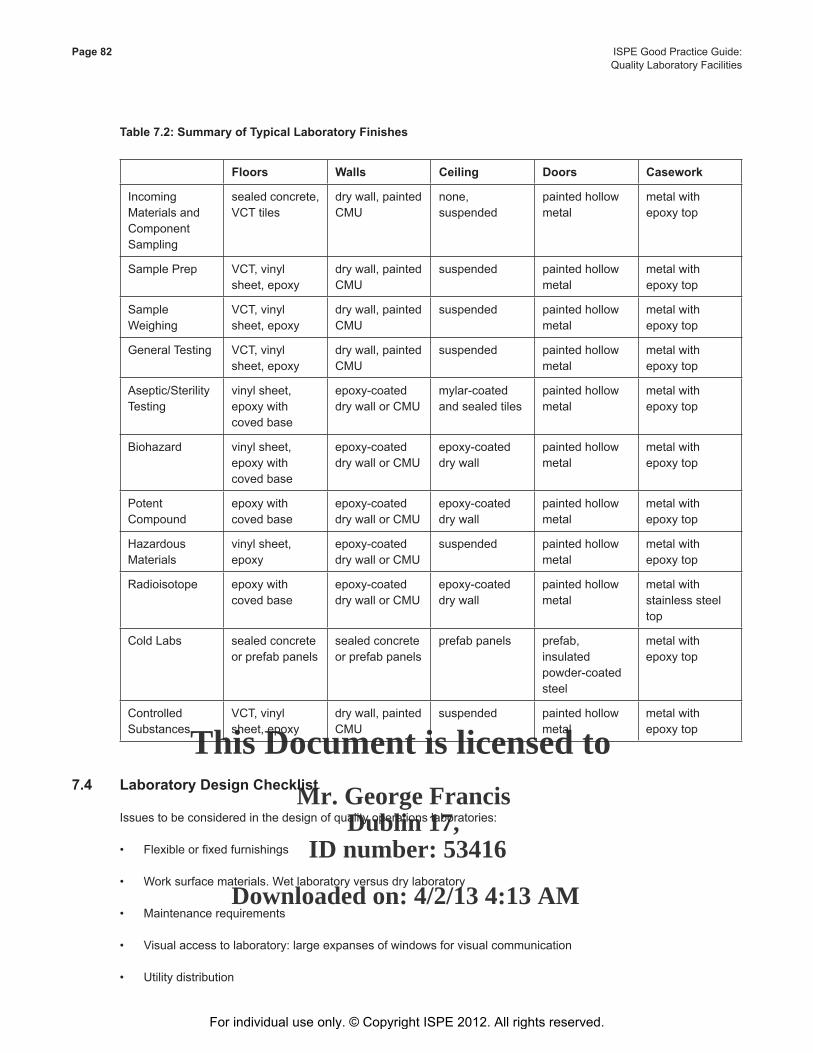
This Document is licensed to
Mr. George FrancisDublin 17,
ID number: 53416
Downloaded on: 4/2/13 4:13 AM
Page 82 ISPE Good Practice Guide: Quality Laboratory Facilities
Table 7.2: Summary of Typical Laboratory Finishes
Floors Walls Ceiling Doors Casework
Incoming MaterialsandComponent Sampling
sealedconcrete,VCTtiles
drywall,paintedCMU
none,suspended
painted hollow metal
metal with epoxytop
Sample Prep VCT,vinylsheet,epoxy
drywall,paintedCMU
suspended painted hollow metal
metal with epoxytop
Sample Weighing
VCT,vinylsheet,epoxy
drywall,paintedCMU
suspended painted hollow metal
metal with epoxytop
General Testing VCT,vinylsheet,epoxy
drywall,paintedCMU
suspended painted hollow metal
metal with epoxytop
Aseptic/SterilityTesting
vinylsheet,epoxywithcoved base
epoxy-coateddrywallorCMU
mylar-coatedand sealed tiles
painted hollow metal
metal with epoxytop
Biohazard vinylsheet,epoxywithcoved base
epoxy-coateddrywallorCMU
epoxy-coateddry wall
painted hollow metal
metal with epoxytop
Potent Compound
epoxywithcoved base
epoxy-coateddrywallorCMU
epoxy-coateddry wall
painted hollow metal
metal with epoxytop
Hazardous Materials
vinylsheet,epoxy
epoxy-coateddrywallorCMU
suspended painted hollow metal
metal with epoxytop
Radioisotope epoxywithcoved base
epoxy-coateddrywallorCMU
epoxy-coateddry wall
painted hollow metal
metal with stainless steel top
Cold Labs sealed concrete or prefab panels
sealed concrete or prefab panels
prefab panels prefab,insulated powder-coatedsteel
metal with epoxytop
Controlled Substances
VCT,vinylsheet,epoxy
drywall,paintedCMU
suspended painted hollow metal
metal with epoxytop
7.4 Laboratory Design Checklist
Issues to be considered in the design of quality operations laboratories:
• Flexibleorfixedfurnishings
• Worksurfacematerials.Wetlaboratoryversusdrylaboratory
• Maintenancerequirements
• Visualaccesstolaboratory:largeexpansesofwindowsforvisualcommunication
• Utilitydistribution
For individual use only. © Copyright ISPE 2012. All rights reserved.
This Document is licensed to
Mr. George FrancisDublin 17,
ID number: 53416
Downloaded on: 4/2/13 4:13 AM
ISPE Good Practice Guide: Page 83Quality Laboratory Facilities
• Resourceconstrainedactivities
• Sharedareasorequipment
• Analysisanddocumentationmethods
• Alarmsandmonitoring
• Instrumentlogs,dataports,qualification,andcalibration
• Structure–vibrationcontrolandisolation
• Specificareaswithgreaterairfiltration
• Redundancy/AHUseparations(zoning)
• Systemandcomponentcommissioningversusvalidation
• Glasswash/autoclavesterilization,media/bufferpreparation
• Uninterruptedpowersupply–housesystemversuslocalizedbatteries
• Refrigerator,freezer,incubators
• Phoneanddataportdistributionandnetworking
• Wastemanagementandhandling
• Costimplicationscapitalandoperational
• Aestheticconsiderations
• Producttestingrequirements(type,duration,numberoftests)
• Personnel(andshift)
• Lifesafety/codecomplianceandegressrequirements
• Productivity
• Efficiency
• Expansion
• Equipmentrequirements
• Benchheightrequirements
• Meetingrequirements
• Foodandcoffeeroomlocations
• Garmentingrequirements
• Commissioningandqualificationrequirements
For individual use only. © Copyright ISPE 2012. All rights reserved.
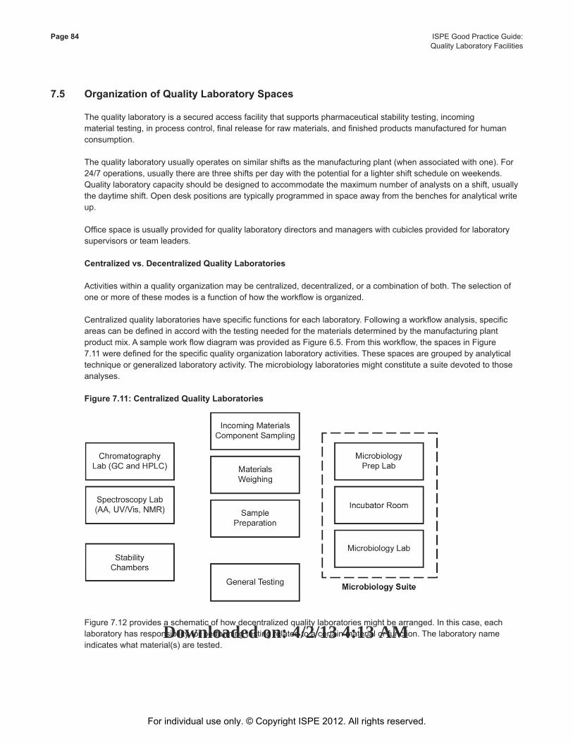
This Document is licensed to
Mr. George FrancisDublin 17,
ID number: 53416
Downloaded on: 4/2/13 4:13 AM
Page 84 ISPE Good Practice Guide: Quality Laboratory Facilities
7.5 Organization of Quality Laboratory Spaces
Thequalitylaboratoryisasecuredaccessfacilitythatsupportspharmaceuticalstabilitytesting,incomingmaterialtesting,inprocesscontrol,finalreleaseforrawmaterials,andfinishedproductsmanufacturedforhumanconsumption.
Thequalitylaboratoryusuallyoperatesonsimilarshiftsasthemanufacturingplant(whenassociatedwithone).For24/7operations,usuallytherearethreeshiftsperdaywiththepotentialforalightershiftscheduleonweekends.Qualitylaboratorycapacityshouldbedesignedtoaccommodatethemaximumnumberofanalystsonashift,usuallythedaytimeshift.Opendeskpositionsaretypicallyprogrammedinspaceawayfromthebenchesforanalyticalwriteup.
Officespaceisusuallyprovidedforqualitylaboratorydirectorsandmanagerswithcubiclesprovidedforlaboratorysupervisors or team leaders.
Centralized vs. Decentralized Quality Laboratories
Activitieswithinaqualityorganizationmaybecentralized,decentralized,oracombinationofboth.Theselectionofoneormoreofthesemodesisafunctionofhowtheworkflowisorganized.
Centralizedqualitylaboratorieshavespecificfunctionsforeachlaboratory.Followingaworkflowanalysis,specificareascanbedefinedinaccordwiththetestingneededforthematerialsdeterminedbythemanufacturingplantproductmix.AsampleworkflowdiagramwasprovidedasFigure6.5.Fromthisworkflow,thespacesinFigure7.11weredefinedforthespecificqualityorganizationlaboratoryactivities.Thesespacesaregroupedbyanalyticaltechnique or generalized laboratory activity. The microbiology laboratories might constitute a suite devoted to those analyses.
Figure 7.11: Centralized Quality Laboratories
Figure7.12providesaschematicofhowdecentralizedqualitylaboratoriesmightbearranged.Inthiscase,eachlaboratory has responsibility for performing testing related to a certain material or function. The laboratory name indicateswhatmaterial(s)aretested.
For individual use only. © Copyright ISPE 2012. All rights reserved.
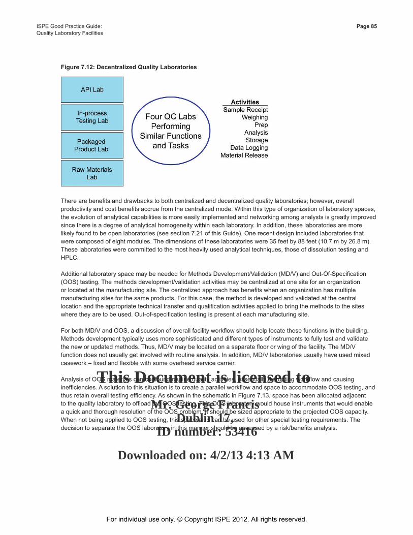
This Document is licensed to
Mr. George FrancisDublin 17,
ID number: 53416
Downloaded on: 4/2/13 4:13 AM
ISPE Good Practice Guide: Page 85Quality Laboratory Facilities
Figure 7.12: Decentralized Quality Laboratories
Therearebenefitsanddrawbackstobothcentralizedanddecentralizedqualitylaboratories;however,overallproductivityandcostbenefitsaccruefromthecentralizedmode.Withinthistypeoforganizationoflaboratoryspaces,the evolution of analytical capabilities is more easily implemented and networking among analysts is greatly improved sincethereisadegreeofanalyticalhomogeneitywithineachlaboratory.Inaddition,theselaboratoriesaremorelikelyfoundtobeopenlaboratories(seesection7.21ofthisGuide).Onerecentdesignincludedlaboratoriesthatwerecomposedofeightmodules.Thedimensionsoftheselaboratorieswere35feetby88feet(10.7mby26.8m).Theselaboratorieswerecommittedtothemostheavilyusedanalyticaltechniques,thoseofdissolutiontestingandHPLC.
AdditionallaboratoryspacemaybeneededforMethodsDevelopment/Validation(MD/V)andOut-Of-Specification(OOS)testing.Themethodsdevelopment/validationactivitiesmaybecentralizedatonesiteforanorganizationorlocatedatthemanufacturingsite.Thecentralizedapproachhasbenefitswhenanorganizationhasmultiplemanufacturingsitesforthesameproducts.Forthiscase,themethodisdevelopedandvalidatedatthecentrallocationandtheappropriatetechnicaltransferandqualificationactivitiesappliedtobringthemethodstothesiteswheretheyaretobeused.Out-of-specificationtestingispresentateachmanufacturingsite.
ForbothMD/VandOOS,adiscussionofoverallfacilityworkflowshouldhelplocatethesefunctionsinthebuilding.Methodsdevelopmenttypicallyusesmoresophisticatedanddifferenttypesofinstrumentstofullytestandvalidatetheneworupdatedmethods.Thus,MD/Vmaybelocatedonaseparatefloororwingofthefacility.TheMD/Vfunctiondoesnotusuallygetinvolvedwithroutineanalysis.Inaddition,MD/Vlaboratoriesusuallyhaveusedmixedcasework–fixedandflexiblewithsomeoverheadservicecarrier.
AnalysisofOOSmaterialscanconfoundroutinequalityactivities,essentiallydisruptingworkflowandcausinginefficiencies.AsolutiontothissituationistocreateaparallelworkflowandspacetoaccommodateOOStesting,andthusretainoveralltestingefficiency.AsshownintheschematicinFigure7.13,spacehasbeenallocatedadjacenttothequalitylaboratorytooffloadtheOOStesting.ThisOOSlaboratorywouldhouseinstrumentsthatwouldenableaquickandthoroughresolutionoftheOOSproblem.ItshouldbesizedappropriatetotheprojectedOOScapacity.WhennotbeingappliedtoOOStesting,thisspacealsocanbeusedforotherspecialtestingrequirements.ThedecisiontoseparatetheOOSlaboratoryinthismannershouldbeassessedbyarisk/benefitsanalysis.
For individual use only. © Copyright ISPE 2012. All rights reserved.
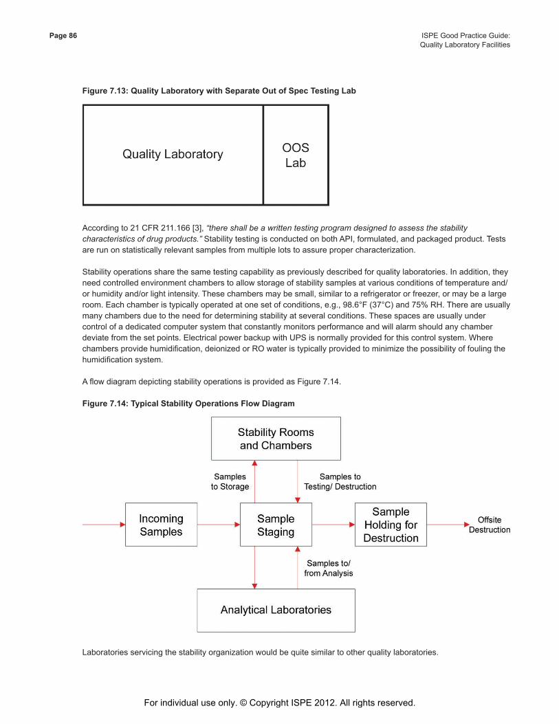
This Document is licensed to
Mr. George FrancisDublin 17,
ID number: 53416
Downloaded on: 4/2/13 4:13 AM
Page 86 ISPE Good Practice Guide: Quality Laboratory Facilities
Figure 7.13: Quality Laboratory with Separate Out of Spec Testing Lab
Accordingto21CFR211.166[3],“there shall be a written testing program designed to assess the stability characteristics of drug products.”StabilitytestingisconductedonbothAPI,formulated,andpackagedproduct.Testsare run on statistically relevant samples from multiple lots to assure proper characterization.
Stabilityoperationssharethesametestingcapabilityaspreviouslydescribedforqualitylaboratories.Inaddition,theyneedcontrolledenvironmentchamberstoallowstorageofstabilitysamplesatvariousconditionsoftemperatureand/orhumidityand/orlightintensity.Thesechambersmaybesmall,similartoarefrigeratororfreezer,ormaybealargeroom.Eachchamberistypicallyoperatedatonesetofconditions,e.g.,98.6°F(37°C)and75%RH.Thereareusuallymany chambers due to the need for determining stability at several conditions. These spaces are usually under control of a dedicated computer system that constantly monitors performance and will alarm should any chamber deviate from the set points. Electrical power backup with UPS is normally provided for this control system. Where chambersprovidehumidification,deionizedorROwateristypicallyprovidedtominimizethepossibilityoffoulingthehumidificationsystem.
AflowdiagramdepictingstabilityoperationsisprovidedasFigure7.14.
Figure 7.14: Typical Stability Operations Flow Diagram
Laboratories servicing the stability organization would be quite similar to other quality laboratories.
For individual use only. © Copyright ISPE 2012. All rights reserved.
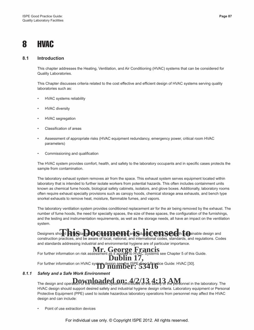
This Document is licensed to
Mr. George FrancisDublin 17,
ID number: 53416
Downloaded on: 4/2/13 4:13 AM
ISPE Good Practice Guide: Page 87Quality Laboratory Facilities
8 HVAC8.1 Introduction
This chapter addresses the Heating, Ventilation, and Air Conditioning (HVAC) systems that can be considered for Quality Laboratories.
ThisChapterdiscussescriteriarelatedtothecosteffectiveandefficientdesignofHVACsystemsservingqualitylaboratories such as:
• HVACsystemsreliability
• HVACdiversity
• HVACsegregation
• Classificationofareas
• Assessmentofappropriaterisks(HVACequipmentredundancy,emergencypower,criticalroomHVACparameters)
• Commissioningandqualification
TheHVACsystemprovidescomfort,health,andsafetytothelaboratoryoccupantsandinspecificcasesprotectsthesample from contamination.
Thelaboratoryexhaustsystemremovesairfromthespace.Thisexhaustsystemservesequipmentlocatedwithinlaboratorythatisintendedtofurtherisolateworkersfrompotentialhazards.Thisoftenincludescontainmentunitsknownaschemicalfumehoods,biologicalsafetycabinets,isolators,andgloveboxes.Additionally,laboratoryroomsoftenrequireexhaustspecialtyprovisionssuchascanopyhoods,chemicalstorageareaexhausts,andbenchtypesnorkelexhauststoremoveheat,moisture,flammablefumes,andvapors.
The laboratory ventilation system provides conditioned replacement air for the air being removed by the exhaust. The numberoffumehoods,theneedforspecialtyspaces,thesizeofthesespaces,theconfigurationofthefurnishings,andthetestingandinstrumentationrequirements,aswellasthestorageneeds,allhaveanimpactontheventilationsystem.
DesignersshouldbefamiliarwithlaboratoryoperationsandindustrialHVAC,alongwithsustainabledesignandconstructionpractices,andbeawareoflocal,national,andinternationalcodes,standards,andregulations.Codesand standards addressing industrial and environmental hygiene are of particular importance.
ForfurtherinformationonriskassessmentasitappliestoHVACSystemsseeChapter5ofthisGuide.
For further information on HVAC system design see the ISPE Good Practice Guide: HVAC [30].
8.1.1 Safety and a Safe Work Environment
The design and operation of the ventilation system contributes to the safety of the personnel in the laboratory. The HVACdesignshouldsupportdesiredsafetyandindustrialhygienedesigncriteria.LaboratoryequipmentorPersonalProtectiveEquipment(PPE)usedtoisolatehazardouslaboratoryoperationsfrompersonnelmayaffecttheHVACdesign and can include:
• Pointofuseextractiondevices
For individual use only. © Copyright ISPE 2012. All rights reserved.
This Document is licensed to
Mr. George FrancisDublin 17,
ID number: 53416
Downloaded on: 4/2/13 4:13 AM
Page 88 ISPE Good Practice Guide: Quality Laboratory Facilities
• Gloveboxes
• Isolators
• Fumehoods
• Bio-safetycabinets
• Ventilatedenclosures
8.1.2 EffectiveandEfficientOperations
TheHVACdesignshouldidentifyoptionswheretherearesignificantoperationalorcapitalcostdifferencesandrankthemagainstatotalcostofownershipmodelthataccountsfor:
• Inflation
• Utilityimpact
• Thecostofcapital
• Optionlifespan
• Estimatedmaintenancecostsforeachinstance
WithinaneffectiveandefficientHVACdesign,selectionorrejectionofoptionsinmechanicaldesignandcontrolsshouldbebasedontheseconsiderations.Typicalkeydecisionsincludeacomparisonoftheinitialcostsagainstthelife cycle costs of a variable air volume system, heat recovery systems, and control system strategies.
8.1.2.1 Environmental Conditions
TheHVACsystemshouldprovideanenvironmentwhichallowsscientistsandtechnicianstoconcentrateontheirworkwithoutdistractionbytheroomconditions,drafts,andnoise.Equipmentcanoperateoverawiderangeofenvironmentalconditionswithconsistenttestresults,sothelimitingfactorwouldbeprovisionofconditionsforhumancomfort.
Workercomfortcanalsoinfluencetheresultsbypromotinggoodworkpractices(e.g.,workersnottouchingtheirskinwhileperformingtests).Insomesituationssweatandparticulatecanaffecttests.
Maximumandminimumroomtemperaturesandhumidityshouldbewithinnationalorlocalhealthguidelines.SeetheASHRAEStandard55(ThermalEnvironmentalConditionsforHumanOccupancy)[50]andtheISOStandard7730(ErgonomicsoftheThermalEnvironment)[51].Conditionsshouldbeadjustedforworkersinprotectiveclothingtoassure their comfort.
Arangeof30%to60%RHisrecommendedforworkercomfortwhereoccupancyiscontinuous.However,assomefacilitieswillhave100%outdoorairsystems,theneedandcostofcomfortdehumidificationandhumidification(wherehumiditywillnotaffecttheproduct)shouldbeassessed.
Verylowhumiditycanleadto:
• malfunctionsorproblemsinsomeoffice,packaging,andelectronicequipment
• risesinthepotentialforstaticdischarges
For individual use only. © Copyright ISPE 2012. All rights reserved.
This Document is licensed to
Mr. George FrancisDublin 17,
ID number: 53416
Downloaded on: 4/2/13 4:13 AM
ISPE Good Practice Guide: Page 89Quality Laboratory Facilities
• increasesindustclingingtosurfaces
• increasesinparticulategenerationfromdryskin
• increasedsusceptibilitytoinfectionforoccupants
High humidity can lead to:
• addedmoistureintheproductsample
• condensationonexteriorwindows
• increasedcorrosioninfurnitureandequipment
• microbialgrowthonsurfaces,inconcealedspacesandinbuildingmaterials
• malfunctionsorproblemsinsomeoffice,packaging,andelectronicequipment
• increasedsusceptibilitytoinfectionforoccupants
8.1.3 ErgonomicsandWorkflow
Typically,qualitylaboratorieshaveextensiveequipmentinventoriesandrequiredsupportspaces.HVACdesignshould account for:
• Specificventilationrequirementsofequipment
• Heatemittedbytheequipmentintothelaboratory
Userworkflowandergonomicdesignsmaycompetewithefficientmechanicaldesign.SuccessfulHVACdesignisacollaborativeeffortbetweenallstakeholdersduringthebasesofdesign,riskassessmentanddesigndevelopment.
8.2 User Requirements
Userrequirementsareafrontendrequirementfordevelopingtheappropriatescopeandcriteriaforalaboratoryfacility(seeChapters3,4,and5ofthisGuide).Fromacustomerperspective,assetrealization,whereadeliveredfacilitymeetsthecustomer’sneedsintermsofefficientoperationalthroughput,isakeymeasureofprojectsuccess.Otherfactorswhichareconsideredcontributionstoasuccessfulprojectinclude:
• Process
• Quality
• Safety:productprotection/operatorprotection
• Operations
• Maintenance
For individual use only. © Copyright ISPE 2012. All rights reserved.
This Document is licensed to
Mr. George FrancisDublin 17,
ID number: 53416
Downloaded on: 4/2/13 4:13 AM
Page 90 ISPE Good Practice Guide: Quality Laboratory Facilities
8.2.1 Process
Adatabaseoftheequipmenttobeinstalledinthelaboratoryshouldbedeveloped(seeChapters2,3,and4ofthisGuide).Thisdatabaseshouldincludethemostrestrictiveenvironmentalrequirements(temperature,humidity,cleanliness,isolation,orbarrier,etc.)foroperationoftheequipmentorforperformingthetestsassociatedwiththeequipment,e.g.,equipmentformicrobiologicaltestingmayrequireanISO5(GradeA)laminarairflowandacontrolled temperature environment.
Otherenvironmentalrequirementsalsoshouldbenoted,e.g.,ascalemayrequireavibrationfreemountingsurfacewithnodirectairflowontothescale.
Thedatabasealsoshouldincludeutilityrequirements,heatemitted,anddemandsforventilationsuchasairflow(constant,start-stop,orvariable)toallowintegrationofequipmentwiththeHVACsystems.Whereheatemittedfiguresarenotavailable,thepowerrequirementscanprovideusefulinformationforadesigner.
8.2.2 Quality
Whereenvironmentalconditionscanimpactatestresult,qualifying/monitoringmaybearequirementifadeterminationhasbeenmadethatthelackofenvironmentalcontrolmaygivenegativetestresults.
Itmaybeappropriatetoapplythesamecontrolsasusedinanequivalentmanufacturingenvironmentsuchas:
• Changerooms
• Airlocks
• Doorinterlocks
• Differentialpressureregimes
• Airfiltration
Typically,HVACzonesandequipmentaresegregatedbythedesignteamintosystems/areaswhichrequireeitherqualificationorcommissioning.
8.2.3 Safety:ProductProtection/OperatorProtection
Userrequirements,asdefinedinSection8.2ofthisGuide,areafrontendrequirementfordevelopingtheappropriatescopeandcriteriaforalaboratoryfacility(seeChapters2,3,and4ofthisGuide).Defineduserrequirementscapturekeydatathatwillimpactthefacilitybydefiningtheareasofconcernassuringtheteamthattheyaretakingintoconsideration product safety and operator protection in the HVAC system.
8.2.4 Operations
Userrequirementsidentifytheplannedoperatingpatternforthelaboratory,e.g.,theshiftsperdayandworkingdaysperweek,anddefinetheallowabledowntime,togetherwiththemaintenancestrategy.Thisinformation,togetherwithinformationontheproductsandprocessestobeperformed(e.g.,exposurerisksandassociatedcontrolstrategies)canbeusedtoestablishredundancyrequirements.ItalsocanensurethattheHVACdesignallowsforsystemmaintenancewithoutaffectingthelaboratoryoperation,e.g.,ifhazardousmaterialsarebeinghandledthenduplexfansystemswithUPS/generatorbackupsystemsmaybeneeded.
For individual use only. © Copyright ISPE 2012. All rights reserved.
This Document is licensed to
Mr. George FrancisDublin 17,
ID number: 53416
Downloaded on: 4/2/13 4:13 AM
ISPE Good Practice Guide: Page 91Quality Laboratory Facilities
8.2.5 Maintenance
8.2.5.1 Importance
Maintenanceisarequirementtoensuringthereliableoperationofthequalitylaboratory.Qualityoperationslaboratory facility failures can affect factory throughput directly. Maintenance schedules should be developed and therequirementsofeachHVACcomponentshouldbeunderstoodandincorporated.Wellplannedmaintenancecanreduceoreliminateunplannedevents,includingequipmentandcontrolsfailureswhichcanrenderafacilityinoperative.
8.2.5.2 Reliability
Reliability of a system can be calculated by multiplying the reliability of each individual component. Reliability is a functionofboththeweakestlinkandthetotalnumberoflinkswhicharelessthan100%reliable.
Ifautilityis99%reliable,theequipmentmechanicalsystemsare95%reliable,andthecontrolsare98%reliable,theoverallsystemis92%reliable.Thismeansthattheutilitymayhaveunplannedevents8%ofthetime(potentially29daysoutofanaverageyear).Appropriatemaintenancecansignificantlyimprovereliability;however,eliminationofallunplanned events is considered impossible or impractical for a given system.
Redundancymaybeusedasaremedyforfailures,e.g.,havingN+1orstandbycapacity;however,theadditionalequipmentaddstocosts.
Thereareseveraltechniquesusedtomonitorsystemperformance,e.g.,vibrationmonitoringofequipment.Forfurtherinformation,seetheISPEGoodPracticeGuide:Maintenance[32].
In regard to reliability, HVAC design can depend on the:
• Requirementforthefacilitytooperatecontinuously
• Planningfororavailabilityofoffsitequalitytestingfacilities
• Availabilityforplannedmaintenanceshut-downs
• Sensitivityofaprocesstoanoutage
• Strengthandperformanceofapredictivemaintenancegroup
8.2.5.3 Cost
Thecostofmaintenancepersonnel,equipment,andpartscanbeevaluatedagainstthesensitivityforfacilitydowntime.Generally,thecostforunplannedoutagesissignificantlyhigherthanthecostofmaintenance,soappropriatestaffing,out-sourcedfunctions,andstocklevelscanbeestimatedusingfacilitymanagementgoodpractices.
8.2.5.4 Access
Physicalaccesstodevicesshouldbeincorporatedintothedesignofthefacility.Incleanorclassifiedspace,itisconsideredgoodpracticetolocatedevicesthatneedmaintenanceoutsideoftheenvelope,inmechanicalequipmentortechnicalspaces.Othersuccessfulplanningtechniquesincludeprovidingsafeandergonomicaccesstocontrolvalve stations and terminal devices.
Formaintenance,HVACsystemstypicallyrequireregularaccessto:
• Lubricationpoints
For individual use only. © Copyright ISPE 2012. All rights reserved.
This Document is licensed to
Mr. George FrancisDublin 17,
ID number: 53416
Downloaded on: 4/2/13 4:13 AM
Page 92 ISPE Good Practice Guide: Quality Laboratory Facilities
• Drivebelts
• Electronicassemblies
• Interfacepanels
• Actuators,testingports,andfilters
Majorcomponentswhichneedlessfrequentmaintenanceandaccessinclude:
• Controlvalvestations
• Motors
• Fan
• Louversanddampers
• Coilsections
• Drainpans
• Drainpiping
• Draincleanoutfittings
• Strainers
• Firedampers
• Automationpowersupplies
8.2.5.5 Equipment
Equipmentselectioncaninfluencemaintenancerequirements,e.g.,selectionofanairflowmonitoringstationthatrequiresfrequentcalibrationwillcostmoreoverthelifespanthanadevicewhichrequiresinfrequentoroccasionalreferencechecks.Whenequipmentselectionsarebasedoneconomy,acompletestudyshouldreferencethemanufacturer’sinformationonthefrequencyofmaintenance(e.g.,equipmentcalibration,cleaning,alignment,inspection, tightening, and failure rates).
8.2.5.6 Monitoring
Monitoringdevicescanconsistofremoteandlocaldatagatheringtechnology,SCADA,webbasedI/O,on-boarddiagnostics,andvisual/videosurveillance.Thegeneralgoalofmonitoringtechnologyistoreducetheoveralldependencyonpersonnel,andincreasethereliabilitybyautomatingthecomparisonofreal-timedataversusacceptedcriteriatodetectorpredictfailureandpre-failureconditions.
Generalmonitoringinput/outputdevicescanbe:
• Thermal
• Pressure
• Level
For individual use only. © Copyright ISPE 2012. All rights reserved.
This Document is licensed to
Mr. George FrancisDublin 17,
ID number: 53416
Downloaded on: 4/2/13 4:13 AM
ISPE Good Practice Guide: Page 93Quality Laboratory Facilities
• Position
• Acceleration • Airorwaterflow
Monitoring data points can be expensive and are dependent on reliability. An evaluation of monitoring should include a factor for the maintenance of or the failure of the monitoring system itself. In general, critical monitoring of single pointfailures,andmonitoringthatsupportspredictivefailureisgenerallyworththecostofthepoints.
8.3 HVAC Design Parameters
HVACdesignparametersshouldbeidentifiedduringthedevelopmentoftheuserrequirementsasdefinedinChapters2,3,and4ofthisGuide.TheuserrequirementsshoulddefinetheconditionstobemetallowingfortheappropriateselectionofcomponentstoensurethattheHVACsystemwillperformasrequired.
8.3.1 HVACDesignCriteria
This section is not intended as a design instruction guide for engineers. Existing design guides are available and shouldbeutilizedasnecessary(seetheISPEGoodPracticeGuide:HVAC[30]).
8.3.1.1 Space Loads and Calculations
Theventilationrequirementsforalaboratorydesignshouldaccountfortheactualloadsusingaroom-by-roomanalysis,asmanylaboratoryspacesareheatloaddriven.Genericheatloadspersquarefootshouldnotbeusedfordesignvaluesforlightingandequipment.
8.3.1.2 Ambient Outdoor Design Conditions
Generally,qualitylaboratorieswilluseasignificantamountofoutsideairduetomakeupairrequirements(e.g.,fumehoods, biosafety cabinets, and local exhaust ventilation points). Selection of appropriate outside air design conditions isimportant,asthiswilldrivethecapacityofutilitysystems.
Outdoordesignconditionsshouldbebasedonhistoricallocalweatherdatarecords;i.e.,ASHRAEorlocalweatherdata.Itisconsideredgoodengineeringpracticetoselectambientoutdoordesignconditionsthatarelikelytooccurover most of the cooling and heating periods. Generally, ambient outdoor design conditions are not selected for recordedextremes,i.e.,highestorlowesttemperatureeverrecorded.Thedesignshouldincorporatesomelevelofriskanalysis,asdefinedinChapter6ofthisGuide,toevaluatethecost,probabilityofoccurrence,andimpactontheprocesswithinthelaboratory.
8.3.1.3 Indoor Temperature and Humidity Conditions
Temperatureandhumidityconditionsaredefinedasthosethat,undernormalcircumstances,provideacomfortableworkingenvironment.
Therecanbeinstanceswheretemperatureandhumidityconditionsaredeterminedbyproductorprocesses.
Wherelaboratoryareashavedifferenttemperatureandhumidityconditions(zones),dedicatedHVACsystemsshouldbeconsideredforeachzoneoftemperatureandhumiditycontrol.ConsolidationofHVACsystemstoreduceinitialcost should be evaluated against installed cost and operating cost.
Individual areas may need separate thermostatic control (e.g., local terminal reheaters) due to variation in cooling loads from area to area and potential impact on the testing performed. Areas of similar use and internal heat gain can becombinedinasinglezone.
For individual use only. © Copyright ISPE 2012. All rights reserved.
This Document is licensed to
Mr. George FrancisDublin 17,
ID number: 53416
Downloaded on: 4/2/13 4:13 AM
Page 94 ISPE Good Practice Guide: Quality Laboratory Facilities
Humidificationshouldbecontrolledtomaintainastableenvironment.Whereroomloadsaresimilarandstable,thiscanbeaccomplishedcentrallythroughanairhandlingunit-mountedhumidifier.Forsystemswherecentrallylocatedhumidifierscannotmaintaindesignhumiditylevels,useofterminalhumidifiersshouldbeconsidered.
Wheresteamhumidificationisusedtomaintainwinterhumidityconditions,thequalityofthesteamshouldbeconsidered.Impactonproductqualityandtestingalsoshouldbeconsidered.Plantsteammaycontainchemicaladditivesthatinhibitcorrosion,butmayaffectprocesstestresults.Theseconditionsmayrequiretheuseofadditivefreesteam,whichisnormallygeneratedfromReverseOsmosis(RO)systems.
8.3.1.4 Pressurization
Qualitylaboratoriesmaybedesignedwithnegativepressurerelativetoadjacentcorridorsandoffices,sothatcontaminants, fumes, or smells do not migrate into these areas. The generally preferred method of achieving spacerelativepressurizationisbymaintainingafixeddifferentialbetweensupplyandexhaustairflows.Roompressurizationmonitoringisnotusuallyrequiredinthissituation.
Specificareaswithinalaboratorymayberequiredtobepositivepressurerelativetosurroundingareas.Intermediateairlocksmaybeusedwherepressurizationisrequiredtomanageairflowdirectionforanarea.Ifroomdifferentialpressure is considered a critical parameter for in product testing, monitoring and control may be needed.
8.3.1.5 Ventilation Ventilationdesignshoulddeterminetheminimumrequirementforsupplyairbasedonthedissipationoftheheat
loadsbylaboratoryequipment,environmentalrequirements,buildingenvelope,andpersonnel.
Note:theserequirementsusuallyexceedtheminimumventilationrequirementsforthespace.
Laboratoryequipment,whichincludesventilatedenclosures(e.g.,biosafetycabinets,fumehoods)shouldbeidentifiedintheHVACdesign.Thistypeofequipmentshouldbeintegratedintotheventilationandcontrolsystems,particularlyintwospeedorvariableairvolumesystems.
Fireandexplosiveconditionsshouldbeconsideredinthedesignofqualitylaboratoryventilationsystems.
Itmaybeappropriatetoincurthecostsofprovidingcontrolstothelaboratoryequipmenttominimizetheventilationrequirements,e.g.,extractairvolumecontrolonafumehood.Minimizationofventilationratesshouldmaintainasafeenvironment for personnel.
8.3.1.6 Design Air Change Rates
Airchangeratesshouldbebasedonmake-upairrequirementsorheatload.
Theproperairflowratesandairmanagementstrategy(airlockconfiguration)shouldbeestablishedforareasthataredesignedtomaintainacleanlinessclassification.(Mostareasofaqualitylaboratoryarenotrequiredtoachieveacleanlinessclassification,e.g.,GradeD.)
Airchangeratesalsomaybedrivenbyinternalheatloadfrompersonnel,lights,andequipment.Forfurtherinformationonequipmentheatload,seeSection8.3.1.8ofthisGuide.
8.3.1.7 Filtration
Generally,qualitylaboratoryareasdonothavetoachieveaparticulateclassification.Theacceptedindustrypracticeforfiltrationlevelsistypically,aprefilterandfinalfilter(i.e.,ASHRAEMERV8andfinalfilterASHRAEMERV13or14).Localconditionsmayrequirealternativestrategiestomanagethequalityofthesupplyair.
For individual use only. © Copyright ISPE 2012. All rights reserved.
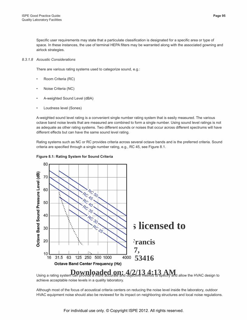
This Document is licensed to
Mr. George FrancisDublin 17,
ID number: 53416
Downloaded on: 4/2/13 4:13 AM
ISPE Good Practice Guide: Page 95Quality Laboratory Facilities
Specificuserrequirementsmaystatethataparticulateclassificationisdesignatedforaspecificareaortypeofspace.Intheseinstances,theuseofterminalHEPAfiltersmaybewarrantedalongwiththeassociatedgowningandairlockstrategies.
8.3.1.8 Acoustic Considerations
Therearevariousratingsystemsusedtocategorizesound,e.g.:
• RoomCriteria(RC) • NoiseCriteria(NC)
• A-weightedSoundLevel(dBA)
• Loudnesslevel(Sones)
A-weightedsoundlevelratingisaconvenientsinglenumberratingsystemthatiseasilymeasured.Thevariousoctavebandnoiselevelsthataremeasuredarecombinedtoformasinglenumber.Usingsoundlevelratingsisnotasadequateasotherratingsystems.Twodifferentsoundsornoisesthatoccuracrossdifferentspectrumswillhavedifferent effects but can have the same sound level rating.
Rating systems such as NC or RC provides criteria across several octave bands and is the preferred criteria. Sound criteriaarespecifiedthroughasinglenumberrating,e.g.,RC45,seeFigure8.1.
Figure 8.1: Rating System for Sound Criteria
UsingaratingsystemcanprovideamoreaccurateandobjectivemethodtospecifyandallowtheHVACdesigntoachieveacceptablenoiselevelsinaqualitylaboratory.
Although most of the focus of acoustical criteria centers on reducing the noise level inside the laboratory, outdoor HVACequipmentnoiseshouldalsobereviewedforitsimpactonneighboringstructuresandlocalnoiseregulations.
For individual use only. © Copyright ISPE 2012. All rights reserved.
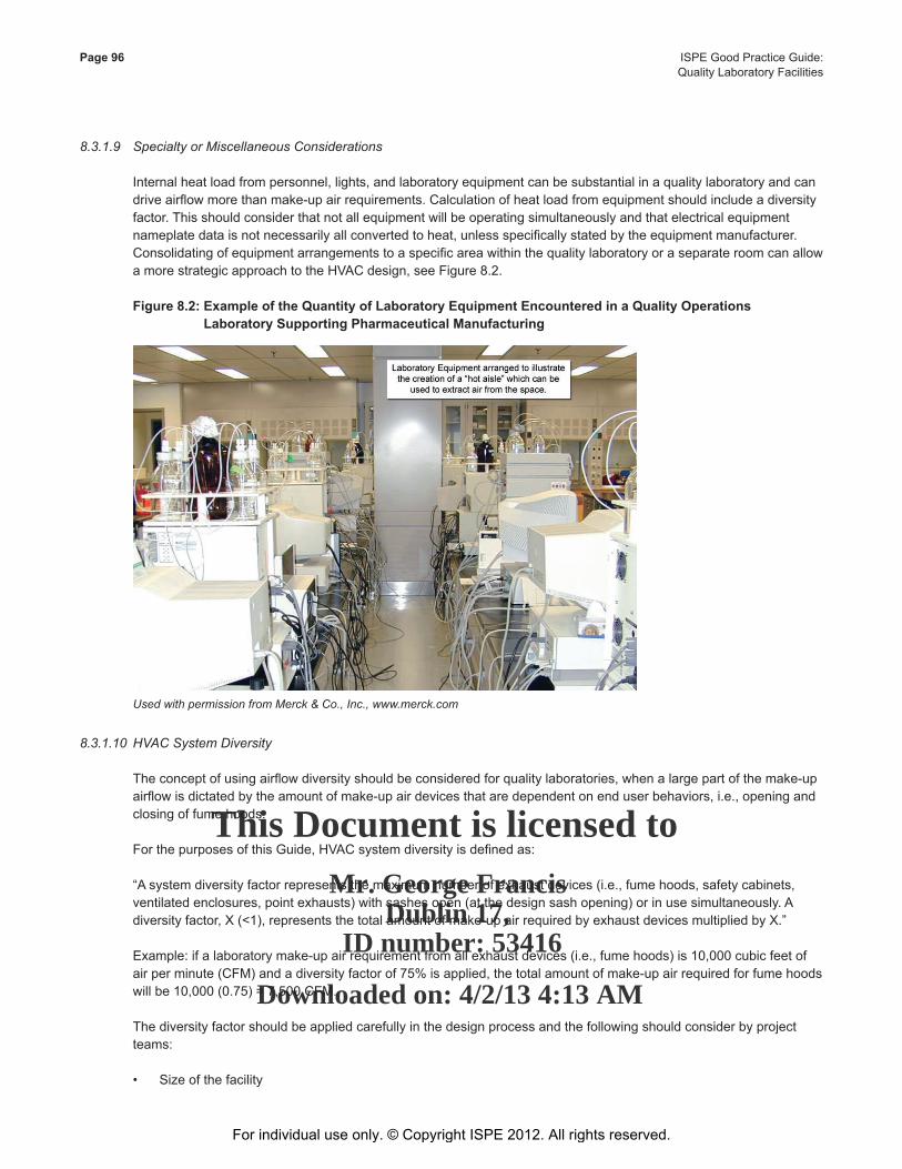
This Document is licensed to
Mr. George FrancisDublin 17,
ID number: 53416
Downloaded on: 4/2/13 4:13 AM
Page 96 ISPE Good Practice Guide: Quality Laboratory Facilities
8.3.1.9 Specialty or Miscellaneous Considerations
Internalheatloadfrompersonnel,lights,andlaboratoryequipmentcanbesubstantialinaqualitylaboratoryandcandriveairflowmorethanmake-upairrequirements.Calculationofheatloadfromequipmentshouldincludeadiversityfactor.Thisshouldconsiderthatnotallequipmentwillbeoperatingsimultaneouslyandthatelectricalequipmentnameplatedataisnotnecessarilyallconvertedtoheat,unlessspecificallystatedbytheequipmentmanufacturer.ConsolidatingofequipmentarrangementstoaspecificareawithinthequalitylaboratoryoraseparateroomcanallowamorestrategicapproachtotheHVACdesign,seeFigure8.2.
Figure 8.2: Example of the Quantity of Laboratory Equipment Encountered in a Quality Operations Laboratory Supporting Pharmaceutical Manufacturing
Used with permission from Merck & Co., Inc., www.merck.com
8.3.1.10 HVAC System Diversity
Theconceptofusingairflowdiversityshouldbeconsideredforqualitylaboratories,whenalargepartofthemake-upairflowisdictatedbytheamountofmake-upairdevicesthataredependentonenduserbehaviors,i.e.,openingandclosing of fume hoods.
ForthepurposesofthisGuide,HVACsystemdiversityisdefinedas:
“A system diversity factor represents the maximum number of exhaust devices (i.e., fume hoods, safety cabinets, ventilatedenclosures,pointexhausts)withsashesopen(atthedesignsashopening)orinusesimultaneously.Adiversityfactor,X(<1),representsthetotalamountofmake-upairrequiredbyexhaustdevicesmultipliedbyX.”
Example:ifalaboratorymake-upairrequirementfromallexhaustdevices(i.e.,fumehoods)is10,000cubicfeetofairperminute(CFM)andadiversityfactorof75%isapplied,thetotalamountofmake-upairrequiredforfumehoodswillbe10,000(0.75)=7,500CFM.
Thediversityfactorshouldbeappliedcarefullyinthedesignprocessandthefollowingshouldconsiderbyprojectteams:
• Sizeofthefacility
For individual use only. © Copyright ISPE 2012. All rights reserved.

This Document is licensed to
Mr. George FrancisDublin 17,
ID number: 53416
Downloaded on: 4/2/13 4:13 AM
ISPE Good Practice Guide: Page 97Quality Laboratory Facilities
• Totalnumberoffumehoods(orsimilarcontainmentdevice)
• Numberoffumehoods(orsimilarcontainmentdevice)perenduser
• Agreeonwhat“fullopen”forafumehoodmeans.Note:dependingonthesasharrangement,thiscantakeonavarietyofdefinitions
• Typeofexhaustcontrols
• Numberofdevicesthatneedtooperatecontinuouslyduetochemicalstoragerequirementsorcontaminationprevention
• Pre-investmentinfuturecapacityforprojectedresearchprograms
Thelistisintendedtohighlightexamplesofdiscussionpointstoreviewwhenconsideringapplyingadiversityfactor.
Anadvantageofapplyingadiversityfactorisalowerinitialcapitalcost.Mechanicalsystemsusuallyaccountforalargeportionofabuilding’scostandinfluencethesizeofabuilding.
8.3.1.11 EnergyEfficiency/Sustainability
HVACsystemdesignshouldincludeathoroughreviewofopportunitiestoincludeenergysavingfeatures.Ifthereareestablishedorganizationalutility,energy,orminimumefficiencyguidesorstandardstheyshouldbeidentifiedand applied in the HVAC design. Evaluation of alternatives should include an energy analysis that compares annual energy costs to initial investments.
In addition, there are established programs, e.g., (Leadership in Energy, Environment, and Design (LEED) that provideaframeworkforbuildingdesign,operations,andmaintenancethatpromoteefficientandsustainablebuildings.Theprocesstakesalifecycleapproachandencompassesmanyaspectsofabuilding,i.e.,impacttolocalenvironment,energy,etc.Theseprogramscanprovidealowerlifecyclecosttooperateandmaintainafacility,aswellaslesstangiblebenefits.
8.3.1.12 HVAC Handling of Biological or Chemical Compounds (Segregation and Containment)
Thehandlingofbiologicalorchemicalcompoundsshouldundergoariskassessmenttocategorizeandrankcompounds to establish the appropriate level of containment. Engineering controls used for containment are considered in order to have the proper context for HVAC design.
Quantitiesofbiologicalorchemicalcompoundshandledinqualitylaboratoriesareusuallysmallerthaninproductionfacilities;therefore,qualitylaboratoriesdonotusuallyhavethesameapproachforengineeringcontrolsandHVACdesign.
Smallerquantitiesallowforhandlingincontainmenttypedevices;e.g.,gloveboxes,biologicalsafetycabinets,andfumehoods,whicharetheprimarymethodofengineeringcontrols.Thetypeofengineeringcontrolusedisusuallydeterminedbytherankingassignedtothecompoundintheriskassessment.Factorsconsideredinclude:
• Exposurelimits
• Typeofcompound,e.g.,liquid,solids,aerosols
Engineeringcontrolsusedinthelaboratorymaybesufficienttoprovideareliableandsubsequentlowriskofexposure so that additional controls are not needed from the HVAC system that serves the area.
For individual use only. © Copyright ISPE 2012. All rights reserved.
This Document is licensed to
Mr. George FrancisDublin 17,
ID number: 53416
Downloaded on: 4/2/13 4:13 AM
Page 98 ISPE Good Practice Guide: Quality Laboratory Facilities
Wheretheassessmentofriskishigh,despitetheuseofengineeringcontrols,additionalmeasurescanbetakenintheHVACdesigntosegregatetheHVACsystem(dedicatedsystem)andprovidedadditionalfiltrationforreturn/exhaustsystems.Inadditional,theareacanbesegregatedinaseparateroomwhichcanactassecondarycontainment.
8.3.2 HVACDesignConsiderations
8.3.2.1 Supply Systems
Supplyairsystemstypicallyincludealloutsideairconditioning,filtering,andsupplyfans.Thesesystemscanbe:
• Individualunitsforeachqualitylaboratory
• Centralstationunitsforeachzone
• Amanifoldofcentralstationunitsforsupplytotheentirequalitylaboratoryblockorbuilding
Advantages for each strategy should be considered and evaluated.
Supplysystemsalsoincludecriticalcomponentsforairvolumecontrolandfinaltrimheating,cooling,andhumidificationrequirements.
8.3.2.2 Exhaust Systems
Exhaust air systems typically include all branch and main ducts, inlet valves or dampers, and individual or central stationfansforexhaustfromthespecificequipment,orentirequalitylaboratoryblockorbuilding.Exhaustre-entrainmentalongwithplacementandvelocitycontrolshouldbeconsideredforqualitylaboratoryexhaust.
ComputationalFluidDynamic(CFD)studiesmaybebeneficial.Thesewouldexaminethewind-wakeimpactoftheexhaustsystemsonfreshairintakesforthefacilityandsurroundingfacilities.
Advantages for each design strategy should be considered and evaluated.
Dependingonthespecifichazards,manifoldexhaustsystemdesigns,especiallyrisersandheaders,canaffectthecontrolzonephilosophyforthefacilityandsuchaspectsshouldbecoordinated.
8.3.2.3 Return Systems
Returnsystemstypicallyincludeairfromnon-contaminatedspacesforre-conditioningatsupplyairsystems.Thesesystemstypicallyincludeterminaldevicesandreturnfanswithreliefairpathsintemperateclimatestoachievemoreeconomic operation.
8.3.2.4 Duct Work
Ductworkcanconsistof:
• Sheetmetal
• Composite
• FiberglassReinforcedPlastic(FRP)
The selection of materials should be based on local codes and regulations and consider the type of vapors that the ductworkmayberequiredtotransport.Access,ductaccessories,sealants,insulation,structuralandconnectingelements, and construction and installation methods are considered critical to HVAC system design.
For individual use only. © Copyright ISPE 2012. All rights reserved.
This Document is licensed to
Mr. George FrancisDublin 17,
ID number: 53416
Downloaded on: 4/2/13 4:13 AM
ISPE Good Practice Guide: Page 99Quality Laboratory Facilities
Theavailableorbuiltinallowanceforfutureincreasestoairvolumerequirementsinthefacility,distributionmains,andrisersshouldbeidentifiedforsheetmetaldesigns.
8.3.3 HVACControlSystems
HVAC control systems should:
• SatisfytherequirementsforcommissioningandqualificationfortheQualityLaboratory
• Havethecapacitytomonitorandcontrolalldevicesinthescope
• Havethespeedandflexibilitytoproduceallaspectsoffacilitycontrolinanacceptablemanner
• Besecure
• Haveconfigurationmanagement
QualitylaboratoriesmayhaveinternalorganizationalrequirementsforGxPequipmentmonitoring.Environmentalmonitoring in critical areas may include differential pressure, particle monitoring, or temperature and humidity monitoring.
Control systems consist of basic analog and digital inputs, and digital and analog outputs. These points monitor andcontrolthespecificvariablesjudgednecessarytocontroltheHVACsystem.Thecontrolsystemtypicallyhasacentralizedordistributedcapacityformathfunctionsforsimpleandcomplexsequenceofoperationsprocesslogic.Thecontinuingdevelopmentofcontrolsystemfunctionalityismakingadvancedsystemsstrategiesaffordableatthecommerciallevel.PIDcontrolloopstrategiescanbecomplementedbycompletelyadaptiveloopstabilizationstrategies. These should be challenged during commissioning to ensure that they perform to meet the user requirements.
Control systems may have proprietary internal communication architectures. In architectural designs, system speed and robust communication stability for all control areas should be established.
Whendecidingwhichmanufacturertouseforabuildingcontrolsystem,inputfromtheproposedmanufacturer’sengineering support should be obtained early in a facility design. This input can help in the decision process to eliminate or accept systems based on the ability to handle the scope.
Controlsystemsmayhavethecapacitytomonitorandcontrolequipmentovercommercialprotocolgateways,suchasBACnet,LonWorks,andModbusorindustrialprotocolssuchasHart/Fieldbus.ThesemakeintegrationofPLCcontrolledterminalequipment(suchasvariablefrequencydrives)possible,andcanhelpprovideanintegratedexpandable solution. Communication protocols for the exportation of monitoring data (SCADA side) also can include protocols,suchasOPCtoconnectinternalshorttermdatahistorywithexternallongtermdatastoragesystems.
Controls systems also should have or provide security and security levels for protection of controlled parameters and controlcode.Therealsoshouldbeintegratedsystemsforrevisioncontrol,backingup,andrestoringcontrolcode,I/Opointconfigurations,controllerconfigurationsinDCS,andcommunicationconfigurations.
The HVAC control system is necessary for the operation and monitoring of the facility devices for HVAC operation. A competeworkingsystemcanhavetheabilitytomanagethefacilityinthemostefficientmannerifplanned,installed,and commissioned to do so.
For individual use only. © Copyright ISPE 2012. All rights reserved.
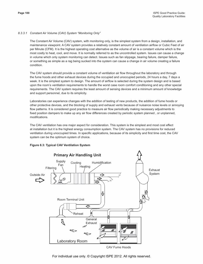
This Document is licensed to
Mr. George FrancisDublin 17,
ID number: 53416
Downloaded on: 4/2/13 4:13 AM
Page 100 ISPE Good Practice Guide: Quality Laboratory Facilities
8.3.3.1 Constant Air Volume (CAV) System “Monitoring Only”
TheConstantAirVolume(CAV)system,withmonitoringonly,isthesimplestsystemfromadesign,installation,andmaintenanceviewpoint.ACAVsystemprovidesarelativelyconstantamountofventilationairfloworCubicFeetofairperMinute(CFM).Itisthehighestoperatingcostalternativeasthevolumeofairisaconstantvolumewhichisthemost costly to heat, cool, and move. It is normally referred to as the uncontrolled system. Issues can cause a change involumewhichonlysystemmonitoringcandetect.Issuessuchasfanslippage,bearingfailure,damperfailure,orsomethingassimpleasaragbeingsuckedintothesystemcancauseachangeinairvolumecreatingafailurecondition.
TheCAVsystemshouldprovideaconstantvolumeofventilationairflowthroughoutthelaboratoryandthroughthefumehoodsandotherexhaustdevicesduringtheoccupiedandunoccupiedperiods,24hoursaday,7daysaweek.Itisthesimplestsystemtodesign.Theamountofairflowisselectedduringthesystemdesignandisbasedupontheroom’sventilationrequirementstohandletheworstcaseroomcomfortconditioningandanyotherspecialrequirements.TheCAVsystemrequirestheleastamountofsensingdevicesandaminimumamountofknowledgeand support personnel, due to its simplicity.
Laboratoriescanexperiencechangeswiththeadditionoftestingofnewproducts,theadditionoffumehoodsorotherprotectivedevices,andtheblockingofsupplyandexhaustventsbecauseofnuisancenoiselevelsorannoyingflowpatterns.Itisconsideredgoodpracticetomeasureairflowperiodicallymakingnecessaryadjustmentstofixedpositiondamperstomakeupanyairflowdifferencescreatedbyperiodicsystemplanned,orunplanned,modifications.
TheCAVventilationhasonemajoraspectforconsideration.Thissystemisthesimplestandmostcosteffectat installation but it is the highest energy consumption system. The CAV system has no provisions for reduced ventilationduringunoccupiedtimes.Inspecificapplications,becauseofitssimplicityandfirsttimecost,theCAVsystem can be the optimum system of choice.
Figure 8.3: Typical CAV Ventilation System
For individual use only. © Copyright ISPE 2012. All rights reserved.

This Document is licensed to
Mr. George FrancisDublin 17,
ID number: 53416
Downloaded on: 4/2/13 4:13 AM
ISPE Good Practice Guide: Page 101Quality Laboratory Facilities
Figure8.3illustratesatypicalCAVventilationsystemappliedtoalaboratoryroomhavingfumehoods.TheCAVsystemdrawsaconstantvolumeofoutsideairintotheairhandlingunit(AHU)whereitisfilteredandconditioned(cooledorheatedandhumidified)tomeettheneedsofthespace.Aconstantvolumeofconditionedair(normallyatacoolertemperaturethantheroomair)issuppliedthroughouttheentireareaservedbythisAHU.Thetemperatureofthe air that is supplied to the individual laboratory room is raised by a room terminal unit reheat coil, to meet occupant comfortorotherneedsofthespecificroom.
8.3.3.2 Constant Air Volume (CAV) System “Monitoring and Controlled”
ThissystemisessentiallythesameastheCAVsystemdescribedinSection8.3.3.1ofthisGuide,althoughitscostis slightly higher because it uses both monitoring and control. The monitoring aspect may be the same as used in the CAVsystemdescribed,butthesystemcanbeadjustedonlybyamechanicadjustingthefixedpositiondamperuntilthedesiredadjustedflowisreached.
The controlled system has an added dynamic of controlled sensing and repositioning, typically done through aBuildingAutomationSystem(BAS).ThissystemhasanequivalentoperatingcosttothatoftheCAVsystem(monitoredonly).Ifthemonitoredonlysystemisnotwellmaintained,itcanpotentiallyhaveahigheroperatingcost.
Thedynamicsofcontrolledareachievedbyuseofvolumedampersequippedwitheitherelectronicorpneumaticdamperactuatorsandwithfeedbackofpositionorairflow.Thecontrolsystemshouldmaintaintherequiredairflowatitsrespectivesetpointinresponsetoactualairflowmeasurement,toensurefullpressureindependentclosedloopcontrol.
This system does not offer any savings in energy consumption because the outcome remains a constant volume systemrunning7daysaweek,24hoursaday.Thissystemisconsideredeasytooperateandisconsideredselfbalancing.
8.3.3.3 Constant Air Volume (CAV) System “Two Position Control”
Thethirdlevelofautomationtoconsiderinlaboratoriesistwopositioncontrolachievedthroughvolumedampers.ThesedampersmaybethetypedescribedinSections8.3.3.1or8.3.3.2ofthisGuide,equippedtooperateintwofixedpositions.Thedifferenceisthatthetwopositionsystemhasameanstoprovidetwolevelsofventilationairflow.Standardsandcodestypicallyallowtheprovisionofalesserventilationratewhenalaboratoryisunoccupied.Thesetbackposition,orunoccupiedmode,isanagreeduponsetbackthatmaintainsthelaboratoryinasafemodewhenitisunoccupied.Itisasystemthatwillsavecostduringtheunoccupiedmode;theairflowisreduced,aswellastheheatingandairmovementrequirements.
Twoseparatelevelsofairflowinatwo-positionCAVsystemisusuallyachievedbyaddingacontroldevice,typicallyavariablespeeddevice,onthefanmotorpowercircuit.ThisenablesthefantoberunatalowerspeedanddeliverlessairthroughtheprimaryAHUandexhaustsystemwhenlessventilationairisrequired.Theactualamountbywhichthe supply can be reduced during the unoccupied time is mostly dependent upon the extent that the exhaust air can be reduced.
Therearetwomethodsofcontrolwhicharemostoftenexecutedasapartofthebuildingautomationsystem.
1. Theuseofatimercontrolwiththepossibilityofoverridingthesetbackwithaphonecalltothebuildingcontrolcenter.
2. Utilizingmotionand/orthelaboratorylightswitchalongwithatimerallowingthesensingofoffhouroccupancythroughthemotiondetectororthelightswitchbeingon.
This system of operation offers a savings in energy consumption because the air exchange rate can be appreciably reducedduringunoccupiedmode,whichcanbeasmanyastwoshiftsperdayduringtheweekandallweekend.
For individual use only. © Copyright ISPE 2012. All rights reserved.

This Document is licensed to
Mr. George FrancisDublin 17,
ID number: 53416
Downloaded on: 4/2/13 4:13 AM
Page 102 ISPE Good Practice Guide: Quality Laboratory Facilities
8.3.3.4 Low Air Volume System – Supports Low Volume Fume Hoods and Can Be a One or Two Position Type of System
ThissystemisthesameasthosedescribedinSections8.3.3.1,8.3.3.2,or8.3.3.3ofthisGuidewiththedifferencebeingthatthefumehoodchosenisofthelowvolumedesign.Inthiscasetheenduserisalreadyreapingthebenefitofthelowvolumefumehooddesign.TheVariableAirVolume(VAV)systemhastheabilitytovarytheamountofsupply and exhaust air to closely match the facility and individual laboratory needs at any given time.
8.3.3.5 VariableAirVolume(VAV)System–theRightAmountofAirflow
This system offers the combination of air volume control throughout via improved safety and economy of operation. Thisisthemostcostlysystemanditisinstalledandoperatedinconjunctionwithabuildingautomationsystem.Thissystemoperatesinconjunctionwithfumehoodsvaryingtheflowofairtomeettherequiredvelocitytomaintaincaptureasthesashispositioned.Withthefumehoodsashfullyopenedthevolumeofairrequiredisequaltothewidthandheightoftheopeningmultipliedbythecapturevelocity.Asthesashisloweredthevolumeofairrequiredislessenedbythewidthtimesthereducedheighttimesthecapturevelocity.Withalaboratorythatisfumehoodintensive the savings in operating cost can be substantial. Closing of the fume hood can support gaining these savings.
InaVAVtypeofventilationsystem,theindividuallaboratoryroomairneedswillvary,mainlyinaccordancewiththeextentthattheVAVfumehoodsashesareopen.Iffumehoodusersopentheirsashesonlywhenaccessisactually needed to the inside of the hoods, the amount of air that needs to be supplied to the laboratory rooms can beminimized.Additionally,firsttimecostsavingsofreducedsizedHVACequipmentthatincludesairdistributionductwork,primarymechanicalsystems(boilers,chillers,pumps,etc.),andprimaryAHUs,canbeachievedbyperforming a diversity calculation. The diversity is calculated based on reasonable and agreed upon assumptions that atanygiventimesomeofthemanyfumehoodswillbeintheclosedposition.Anexampleofthisisaneighthoodlaboratoryandthediversitybeingsixhoodsintheopenpositionandtwohoodsintheclosedpositionatalltimes.Thediversitycalculationwouldbe75%.Thiscalculationwillreducethesizeofthefans,aswellastheheatingandcoolingcoils,andtheductworkandassociatedcomponentsofthesystemforthediversifiedreducedvolume.
Communications to the building automation system is the most important aspect of achieving full VAV control. Volumesofairtotheroomvarywithheating,cooling,andpressurizationneeds.Thevolumesvaryfurtherdependingon number of fume hoods and sash position. In addition, the room is affected by areas of containment for solvent mixinganddispensing,aswellasventilationforspecialequipmentneeds.Thedevicestypicallyusedonthesesystemsarevariablevolumedamperswhicharepositionedinresponsetosensorswithinthesupplyandexhaustductworkoftheroom.Variablevolumedampershousedwithinthefumehoodsarepositionedbyfacevelocitysensorsorsashpositionsensors.Setbackduringunoccupiedhoursisachievedbytimingcircuits,aswellasoccupancy sensors. The system gets more sophisticated as the need to save money over the long term becomes a consideration.
For individual use only. © Copyright ISPE 2012. All rights reserved.
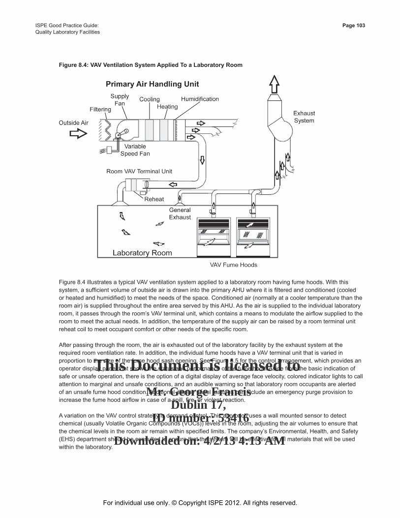
This Document is licensed to
Mr. George FrancisDublin 17,
ID number: 53416
Downloaded on: 4/2/13 4:13 AM
ISPE Good Practice Guide: Page 103Quality Laboratory Facilities
Figure 8.4: VAV Ventilation System Applied To a Laboratory Room
Figure8.4illustratesatypicalVAVventilationsystemappliedtoalaboratoryroomhavingfumehoods.Withthissystem,asufficientvolumeofoutsideairisdrawnintotheprimaryAHUwhereitisfilteredandconditioned(cooledorheatedandhumidified)tomeettheneedsofthespace.Conditionedair(normallyatacoolertemperaturethantheroomair)issuppliedthroughouttheentireareaservedbythisAHU.Astheairissuppliedtotheindividuallaboratoryroom,itpassesthroughtheroom’sVAVterminalunit,whichcontainsameanstomodulatetheairflowsuppliedtotheroom to meet the actual needs. In addition, the temperature of the supply air can be raised by a room terminal unit reheatcoiltomeetoccupantcomfortorotherneedsofthespecificroom.
After passing through the room, the air is exhausted out of the laboratory facility by the exhaust system at the requiredroomventilationrate.Inaddition,theindividualfumehoodshaveaVAVterminalunitthatisvariedinproportiontothesizeofthefumehoodsashopening.SeeFigure8.5forthecontrolarrangement,whichprovidesanoperatordisplaypanelthatshowsthestatusandperformanceofthefumehood.Asidefromthebasicindicationofsafe or unsafe operation, there is the option of a digital display of average face velocity, colored indicator lights to call attentiontomarginalandunsafeconditions,andanaudiblewarningsothatlaboratoryroomoccupantsarealertedof an unsafe fume hood condition. Additional display panel features can include an emergency purge provision to increasethefumehoodairflowincaseofaspill,fire,orviolentreaction.
AvariationontheVAVcontrolstrategyisdemandcontrol.Thisapproachusesawallmountedsensortodetectchemical(usuallyVolatileOrganicCompounds(VOCs))levelsintheroom,adjustingtheairvolumestoensurethatthechemicallevelsintheroomairremainwithinspecifiedlimits.Thecompany’sEnvironmental,Health,andSafety(EHS)departmentshouldbeconsultedtoensurethatthesystemwillbeeffectiveforallmaterialsthatwillbeusedwithinthelaboratory.
For individual use only. © Copyright ISPE 2012. All rights reserved.
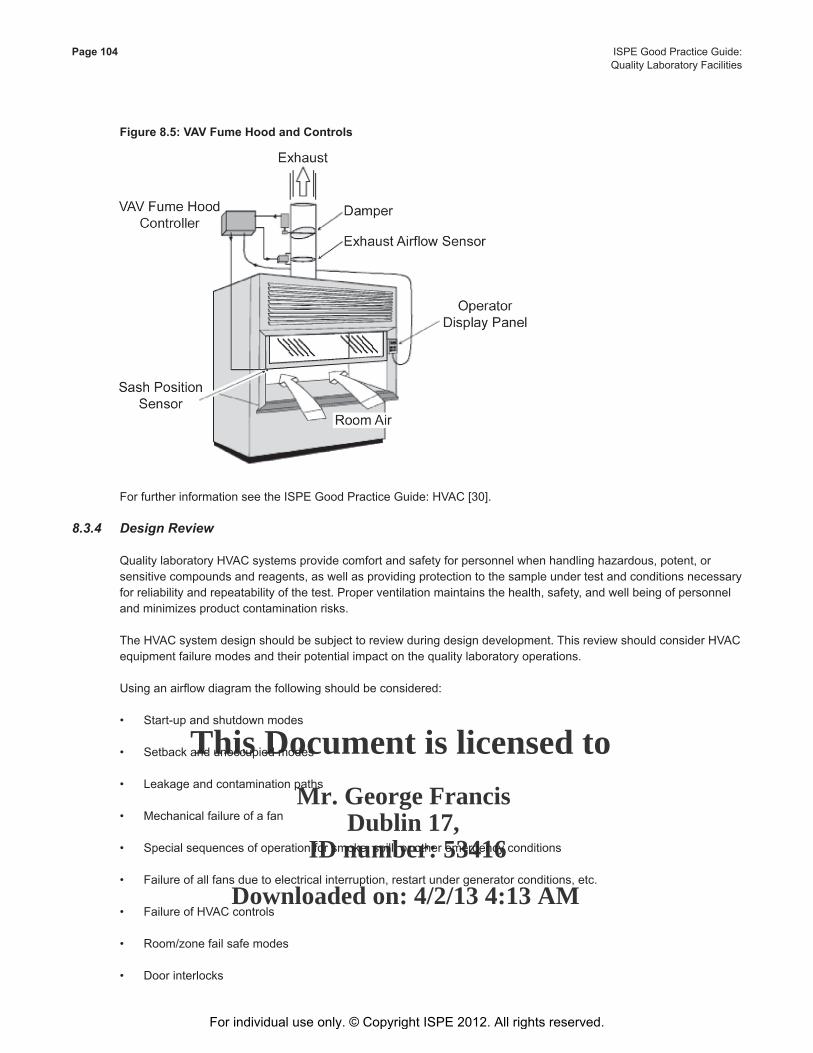
This Document is licensed to
Mr. George FrancisDublin 17,
ID number: 53416
Downloaded on: 4/2/13 4:13 AM
Page 104 ISPE Good Practice Guide: Quality Laboratory Facilities
Figure 8.5: VAV Fume Hood and Controls
For further information see the ISPE Good Practice Guide: HVAC [30].
8.3.4 DesignReview
QualitylaboratoryHVACsystemsprovidecomfortandsafetyforpersonnelwhenhandlinghazardous,potent,orsensitivecompoundsandreagents,aswellasprovidingprotectiontothesampleundertestandconditionsnecessaryforreliabilityandrepeatabilityofthetest.Properventilationmaintainsthehealth,safety,andwellbeingofpersonnelandminimizesproductcontaminationrisks.
TheHVACsystemdesignshouldbesubjecttoreviewduringdesigndevelopment.ThisreviewshouldconsiderHVACequipmentfailuremodesandtheirpotentialimpactonthequalitylaboratoryoperations.
Usinganairflowdiagramthefollowingshouldbeconsidered:
• Start-upandshutdownmodes
• Setbackandunoccupiedmodes
• Leakageandcontaminationpaths
• Mechanicalfailureofafan
• Specialsequencesofoperationforsmoke,spill,orotheremergencyconditions
• Failureofallfansduetoelectricalinterruption,restartundergeneratorconditions,etc.
• FailureofHVACcontrols
• Room/zonefailsafemodes
• Doorinterlocks
For individual use only. © Copyright ISPE 2012. All rights reserved.

This Document is licensed to
Mr. George FrancisDublin 17,
ID number: 53416
Downloaded on: 4/2/13 4:13 AM
ISPE Good Practice Guide: Page 105Quality Laboratory Facilities
• Equipmentinterlocks
• Drainageofcondensatefromcoolingcoilsandhumidifiers
• Useractionineventoffailure(especiallyifpowerfailsandcriticalparameterscannotbemonitored)
• Additionalairflowresistancebecauseofin-linebagfilters,ceilingHEPAfilters
For individual use only. © Copyright ISPE 2012. All rights reserved.

This Document is licensed to
Mr. George FrancisDublin 17,
ID number: 53416
Downloaded on: 4/2/13 4:13 AM
For individual use only. © Copyright ISPE 2012. All rights reserved.
This Document is licensed to
Mr. George FrancisDublin 17,
ID number: 53416
Downloaded on: 4/2/13 4:13 AM
ISPE Good Practice Guide: Page 107Quality Laboratory Facilities
9 Electrical9.1 Introduction
This Chapter addresses requirements for electrical systems within quality laboratories. This Chapter covers the concept of critical parameters for the various types of laboratory environments. Specifically, it concentrates on the control of high risk critical parameters as well as design requirements that relate to power distribution, area classification, lighting, grounding, communication, and wiring methods. Consideration is also made of other strong economic and operating factors influencing system design. For further information on Risk Assessment, see Chapter 5 of this Guide.
Detailed design guidance and recommendations are evaluated based on the functionality of the laboratory and it various subsets. Factors such as schedule, budget, reliability, economic analysis criteria, and future growth and flexibility are considered to determine electrical system recommendations for any specific situation.
The costs of electrical requirements may be reduced based on reduced motor power consumption by use of alternative technologies, such as isolation and barrier or closed processing systems.
9.2 General Requirements
The systems discussed in this Chapter are not systems which could potentially impact or invalidate test results, as they do not directly influence the finished product specification. Designs should follow Good Engineering Practice (GEP).
9.3 Power Distribution
Although the power system does not potentially impact or invalidate tests results, reliability is important. The effects of loss of power or poor power quality (voltage: interference voltage; frequency, e.g., caused by VFDs) on a critical piece of equipment or instrument should be considered and the resulting failure conditions examined.
It is recommended that for emergency conditions the power availability includes Uninterruptible Power Supply (UPS)
and appropriate line conditioning for critical processes. Consideration for UPS systems and line conditioners should be made for laboratory equipment such as HPLCs and their associated computer support equipment so that a controlled shut down can be accomplished and stored data and programs can be saved.
Redundant fan systems may be employed in support of fume hoods to assure constant performance should one fail avoiding any contamination of the environment while protecting the scientist. These fans may be large and not easily backed up. In case of power failure, the laboratory may need to be evacuated.
Note: Consideration should be given to a three-phase/three-wire system as it is cost effective during construction as well as during operation.
9.4 AreaClassification
Installation of electrical equipment should comply with the requirements of the NFPA 70 [34] or other local country codes (or regional equivalents), such as the NFPA 45 [6]. The installation of electrical equipment should be rated appropriately regarding explosion hazard and in accordance to NEMA specifications.
While electrical area classification is not a GMP issue, it may affect location and type of equipment. It should be considered in conjunction with level of protection requirements.
For individual use only. © Copyright ISPE 2012. All rights reserved.
This Document is licensed to
Mr. George FrancisDublin 17,
ID number: 53416
Downloaded on: 4/2/13 4:13 AM
Page 108 ISPE Good Practice Guide: Quality Laboratory Facilities
In regard to both cost and cleanability, considerations should be made to locate light switches in corridors outside of process rooms or in other electrically non-classified rooms. This would allow for the use of switches rated for general-purpose use, which are much less expensive and easier to keep clean, or which have been moved to an area where cleanability is less of a concern.
These advantages should be weighed against convenience to the operator, especially if it involves leaving a controlled area.
Laboratories requiring solvents for the HPLC process should be evaluated. Typically, an area is designated for solvent blending as well as solvent dispensing. This area should be hazard rated requiring ventilation and specific power requirements. Consideration should be given to providing backup power to the facility especially where air movement is used to maintain the hazard rating of a given area. Additionally, electrical exclusion zones may be appropriate in hazardous working areas.
9.5 Lighting
Recommended lighting and lighting fixtures for GEP include:
1. Lighting level is recommended to be at least 70 ft. candles (750 lux) in the laboratory work areas. Common travel areas should be in compliance with local energy standards. For US installations, one may want to follow the recommendations of the Illumination Engineering Society of North America.
2. All lighting fixtures should be accessible to allow proper maintenance, including the changing of lamps and the repair or replacement of the ballast. This may require the remote placement of the ballast.
3. All lighting fixtures should be properly rated for the area in which they are used, including electrical classification and surface temperature.
4. All lighting fixtures used in laboratory areas should allow for cleaning. Where needed, the fixture should be able to withstand the pressure and temperature of any water streams used for wash down. It may be necessary to use a glass shield instead of plastic.
5. The lighting plan should provide adequate lighting and ease of maintenance.
6. The color rendition and intensity of lighting equipment used for inspection, cleaning, or viewing of colorimetric titrations may be considered critical. If so, they should be considered in conjunction with the inspection or cleaning of equipment.
7. Emergency lighting should be included as needed by the NFPA 101: Life Safety Code [35]. Emergency lighting is expensive and difficult to keep clean; therefore, light fixtures with battery pack should be considered as it is cost effective and, easy to clean and maintain. This battery pack will allow the fixture to provide emergency illumination. Consideration should be given to make provision for an un-switched source for the emergency lighting ballast.
9.6 Grounding
Grounding methods used in a laboratory should be arranged and designed to prevent accumulation of dust or foreign materials or be accessible for cleaning. For example, a static ground connection may be designed using an insulated wire instead of a bare wire. The insulated wire would be less likely to accumulate dusts and would be easier to clean.
For individual use only. © Copyright ISPE 2012. All rights reserved.
This Document is licensed to
Mr. George FrancisDublin 17,
ID number: 53416
Downloaded on: 4/2/13 4:13 AM
ISPE Good Practice Guide: Page 109Quality Laboratory Facilities
In a case with portable equipment, a static grounding reelite should be located in the process room. Wherever flammable liquids are dispensed or transferred grounding cable reelites should be considered. Since grounding reelites are difficult to keep clean, it may be necessary to locate them behind a recessed access panel.
The effect of improper grounding upon electronic equipment may be considered a critical issue in isolated cases; if so, it should be considered in conjunction with the electronic equipment. Isolated ground receptacles should be considered. In areas for analytical balances and where organic solvents or other explosives are handled grounding is necessary.
9.7 Telephones, Paging, and Radio Systems
All communication equipment used in a GMP area should be designed to allow for cleaning. This may require the equipment to be rated for wet locations. Communication equipment used in certain GMP areas should be arranged and designed to prevent any accumulation of dust or foreign materials. For example, paging speakers might be recessed into the wall or ceiling in such areas.
The effect of communication system Radio Frequency Interference (RFI) upon some electronic equipment may be considered critical in isolated cases; if so, the selection of the communication system should be considered in conjunction with the electronic equipment.
9.8 Laboratory Information Management System
The Laboratory Information Management System (LIMS) is in use in quality laboratories for managing the acquisition, reporting, and storage of data. In many laboratories, the LIMS is a manual system using quality control records, hard copied protocols, and operational documents along with the scientist’s notebook. If there is a paper based system with stand alone computerized instruments, such as HPLCs, it is important to incorporate the printouts into the process giving the scientist an audit trail and allowing checks to be made on the data in the logbook against electronic data.
In developing the electrical requirements for the quality laboratory it is important to know the LIMS system in use. Computerized LIMS systems may supplement existing manual systems or replacing manual systems with a fully computerized system. Computers which are stand alone automation and control systems as well as data collection devices associated with testing equipment are not part of the LIMS system. These systems perform only limited functions related to a single activity such as the automation and control dedicated to a single device such as the GC or HPLC. These control type computers typically are integrated into the LIMS computerized system which can be beyond the bounds of the laboratory to quality management and reporting centers.
The LIMS equipment has to be considered when developing the overall laboratory electrical and automation needs. Dedicated circuits are a consideration that will eliminate power fluctuations caused by other laboratory equipment. Uninterruptible power supplies either dedicated at the circuit level or centralized should be considered. Usually the philosophy is protection of the equipment rather than maintaining equipment operation during power failures. UPS systems, sized to allow the controlled shut down of this equipment, usually is the choice for cost considerations as well as operation efficiency and safety.
In support of the LIMS network throughout designers should consider what is provided in the way of communications wiring and point of use jacks. Additionally, specialty lighting needs to be considered to avoid glair and allow for the comfort of the operator during long term use.
For individual use only. © Copyright ISPE 2012. All rights reserved.

This Document is licensed to
Mr. George FrancisDublin 17,
ID number: 53416
Downloaded on: 4/2/13 4:13 AM
Page 110 ISPE Good Practice Guide: Quality Laboratory Facilities
9.9 Wiring Methods
Wiring should be designed to allow proper maintenance including the accessibility to junction boxes and outlet boxes.
Conduits and raceways should be labeled for ease of identification.
Wiring methods and materials should be compatible with the process materials. For example, a PVC coated conduit may be needed.
Wiring should meet the requirements of the latest edition of the NEC.
Signal and power wiring should be separated to avoid noise crosstalk.
Wiring in GMP areas should allow for cleaning of exposed surfaces. For example, wiring devices may be designed to withstand washes and to prevent any accumulation of dust or foreign materials. This may require the use of flush mounted boxes, and the placement of conduits in areas outside the operating areas, with minimum penetrations into the operating area. Sealing conduits between areas may be necessary.
For individual use only. © Copyright ISPE 2012. All rights reserved.
This Document is licensed to
Mr. George FrancisDublin 17,
ID number: 53416
Downloaded on: 4/2/13 4:13 AM
ISPE Good Practice Guide: Page 111Quality Laboratory Facilities
10 Laboratory Site Utility and Support Systems10.1 Introduction
In addition to the utilities normally needed such as domestic water and standard electricity, specialty support systems such as purified water, compressed air, and site support systems infrastructure need to be considered in support of the quality laboratory. The size and extent of a new or expanded laboratory can trigger a power substation expansion or require a new stand alone substation. Centralized boiler, chiller, and emergency generator capacity should be tested to meet the new requirements.
Chilled water requirements, typically provided at a temperature of 43°F (6°C) or cooling to relieve the high heat stress generated by specific devices should be considered. For autoclaves, a sufficient supply of steam and return of condensate will be needed or as an alternative sufficient electricity to generate steam in place with a supplier provided steam generator. A supply of compressed air, usually with a minimum pressure requirement of 6 bar (87 psi) is necessary to operate larger autoclaves.
Varying grades of water are essential to various use points within a laboratory. For use points such as autoclaves and environmental chambers, pretreatment of the water helps to avoid buildup within the steam generator or humidifier systems. For the various quality tests, the necessary level of water purity can be achieved by point of use final filtration systems supplied by the potable water system. Where the laboratory is supplied from the same generation system as the manufacturing area, it may be necessary to separate the systems, using a break tank to remove any risk of cross contamination.
10.2 Laboratory Water
Laboratory water requirements may differ from those for manufacturing. This Chapter provides an overview of the different laboratory water purification and distribution approaches available, as well as a step by step method to help to determine what type of system design will best meet a the user’s needs.
10.2.1 System Design Considerations
Water quality requirements for laboratory purposes vary widely depending upon the type of analysis to be performed and the governing organization.
The determination of laboratory water needs may be complex, as pharmaceutical waters are focused on manufacturing applications. Non-pharmacopeial related agencies, which cover water quality for laboratory purposes, such as ISO, ASTM, CLSI, typically are used as a source of information.
The wide range of user needs leads to a variety of possible approaches. Specific laboratory user information is needed to design a cost effective and efficient solution. The design team should provide information including, but not limited to, the issues listed:
DefiningUserNeeds
1. What laboratory tasks will require water?
2. What quality of water is needed for each task?
3. What are the regulations that must be complied with?
4. What is the location of each task?
5. Is there a work pattern for each task?
For individual use only. © Copyright ISPE 2012. All rights reserved.
This Document is licensed to
Mr. George FrancisDublin 17,
ID number: 53416
Downloaded on: 4/2/13 4:13 AM
Page 112 ISPE Good Practice Guide: Quality Laboratory Facilities
6. Can these tasks be clustered in various laboratory locations (e.g., by water quality needed, analytes of concern)?
7. Can one group of tasks be served by one POU outlet?
8. How much water is needed at each POU and by task or task group?
SolutionDesignBasedonUserNeeds
1. What points of use are needed?
2. What water characteristics (quality, etc.) are needed at each point?
3. What purification technologies could be used to produce the water qualities required?
4. What types of distribution system could be suitable?
5. Other parameters to be considered, such as:
a. Building characteristics
b. Laboratory architecture
c. Criticality of water in the process
d. Water source options
e. Ergonomics of use points and drains
f. Economics
10.2.2 Determining User Needs
10.2.2.1 Quality Needs
Laboratories often require a selection of waters with distinct purity specifications, dependent upon analytical applications and regulatory requirements. Compendial procedures will need to use compendial specified waters.
Potential impurities in PW may be grouped into:
• Inorganic ions (typically monitored as conductivity or resistivity, or by specific chemical tests)
• Organic compounds (typically monitored as TOC or by specific tests)
• Bacteria (monitored by cultivative total microbial plate counts or other methods)
• Endotoxins (monitored by LAL test)
• Nucleases (monitored by specific enzyme assays)
• Particulates (typically managed by filtration, but not monitored usually)
• Gases (typically managed by degas/purification equipment and monitored by specific tests, if required)
For individual use only. © Copyright ISPE 2012. All rights reserved.

This Document is licensed to
Mr. George FrancisDublin 17,
ID number: 53416
Downloaded on: 4/2/13 4:13 AM
ISPE Good Practice Guide: Page 113Quality Laboratory Facilities
Within any of these groups, particular substances also may have a specific interference in a particular test, such as components that produce over-lapping peaks in chromatography or contaminants in the water that are identical to the analytes in the test sample.
Table 10.1 provides guidance regarding the types of impurities that may be important for an application when choosing a water system. Quantified impurity levels are not provided because of the wide variations in water purity needed within any one type of application. Table 10.1 is intended primarily for the design engineer who may not have an analytical laboratory background, and could serve as a basis of discussion with laboratory personnel regarding specific water grade/purity needs.
Table10.1:ImportanceLevel(WidelyObserved)forParameters/ContaminantsinDifferentTechniques*
Technique Application Sensitivity**
ImportanceLeveloftheWaterContaminants
Inorganic Ions
Organic Compounds
Particulates Bacteria Endotoxin Nuclease
Bacterial Culture Low – High Low Medium Medium Medium Low Low
Clinical Biochemistry High Medium Low High Medium Low Low
Electrochemistry Low – High Medium – High
Medium – High
Medium Low – High Very Low Very Low
Electrophoresis (Polyacrylamide Gels)
High High High Medium High Low Low (High for Protease)
Electrophoresis (Agarose Gels)
High High Medium Medium High Low High
Electrophysiology Low – High High High Medium High High High
ELISA Low – High Low Medium Medium High Low Low
Endotoxin Determination
Medium – High
Low – High Medium – High
Medium – High
High High – Very High
Low
Flame-AAS Low – High High Low Medium Medium Very Low Very low
GF-AAS High Very High High High High Low Low
GC Low – High Low – High Medium – High
Medium Low – High Very Low Very Low
GC-MS High High High Medium High Very Low Very Low
General Wet Chemistry Low – High Low Low Medium Low Very Low Very Low
Glassware Washing Low – High Low – High Medium – High
Medium Low – High Low Very Low – Low
Histology Low – High Low Medium Medium Medium Medium Very Low
HPLC Low – High Low – High Medium – High
High Low – High Low Very Low – Low
LC-MS High High High High High Low Low
Hydroponics Low – High Low Medium Medium Low Very Low Very Low
ICP-AES High High Medium Medium High Very Low Very Low
ICP-MS High Very High High High High very Low Very Low
Immunocytochemistry High High High High High High Medium
Ion Chromatography Low – High Medium – Very High
Medium – High
High Medium – High
Very Low Very Low
For individual use only. © Copyright ISPE 2012. All rights reserved.
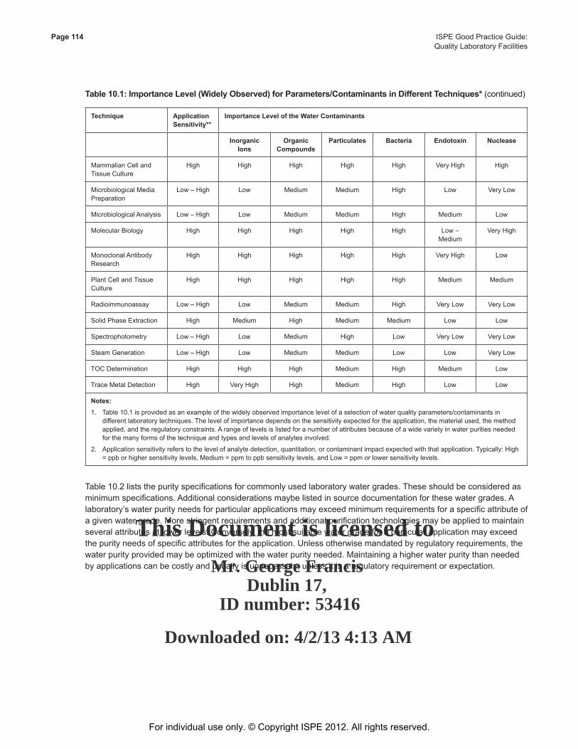
This Document is licensed to
Mr. George FrancisDublin 17,
ID number: 53416
Downloaded on: 4/2/13 4:13 AM
Page 114 ISPE Good Practice Guide: Quality Laboratory Facilities
Table10.1:ImportanceLevel(WidelyObserved)forParameters/ContaminantsinDifferentTechniques*(continued)
Technique Application Sensitivity**
ImportanceLeveloftheWaterContaminants
Inorganic Ions
Organic Compounds
Particulates Bacteria Endotoxin Nuclease
Mammalian Cell and Tissue Culture
High High High High High Very High High
Microbiological Media Preparation
Low – High Low Medium Medium High Low Very Low
Microbiological Analysis Low – High Low Medium Medium High Medium Low
Molecular Biology High High High High High Low – Medium
Very High
Monoclonal Antibody Research
High High High High High Very High Low
Plant Cell and Tissue Culture
High High High High High Medium Medium
Radioimmunoassay Low – High Low Medium Medium High Very Low Very Low
Solid Phase Extraction High Medium High Medium Medium Low Low
Spectrophotometry Low – High Low Medium High Low Very Low Very Low
Steam Generation Low – High Low Medium Medium Low Low Very Low
TOC Determination High High High Medium High Medium Low
Trace Metal Detection High Very High High Medium High Low Low
Notes:1. Table 10.1 is provided as an example of the widely observed importance level of a selection of water quality parameters/contaminants in
different laboratory techniques. The level of importance depends on the sensitivity expected for the application, the material used, the method applied, and the regulatory constraints. A range of levels is listed for a number of attributes because of a wide variety in water purities needed for the many forms of the technique and types and levels of analytes involved.
2. Application sensitivity refers to the level of analyte detection, quantitation, or contaminant impact expected with that application. Typically: High = ppb or higher sensitivity levels, Medium = ppm to ppb sensitivity levels, and Low = ppm or lower sensitivity levels.
Table 10.2 lists the purity specifications for commonly used laboratory water grades. These should be considered as minimum specifications. Additional considerations maybe listed in source documentation for these water grades. A laboratory’s water purity needs for particular applications may exceed minimum requirements for a specific attribute of a given water grade. More stringent requirements and additional purification technologies may be applied to maintain several attributes at lower levels. Conversely, the most suitable water grade for a particular application may exceed the purity needs of specific attributes for the application. Unless otherwise mandated by regulatory requirements, the water purity provided may be optimized with the water purity needed. Maintaining a higher water purity than needed by applications can be costly and usually is unnecessary, unless it is a regulatory requirement or expectation.
For individual use only. © Copyright ISPE 2012. All rights reserved.
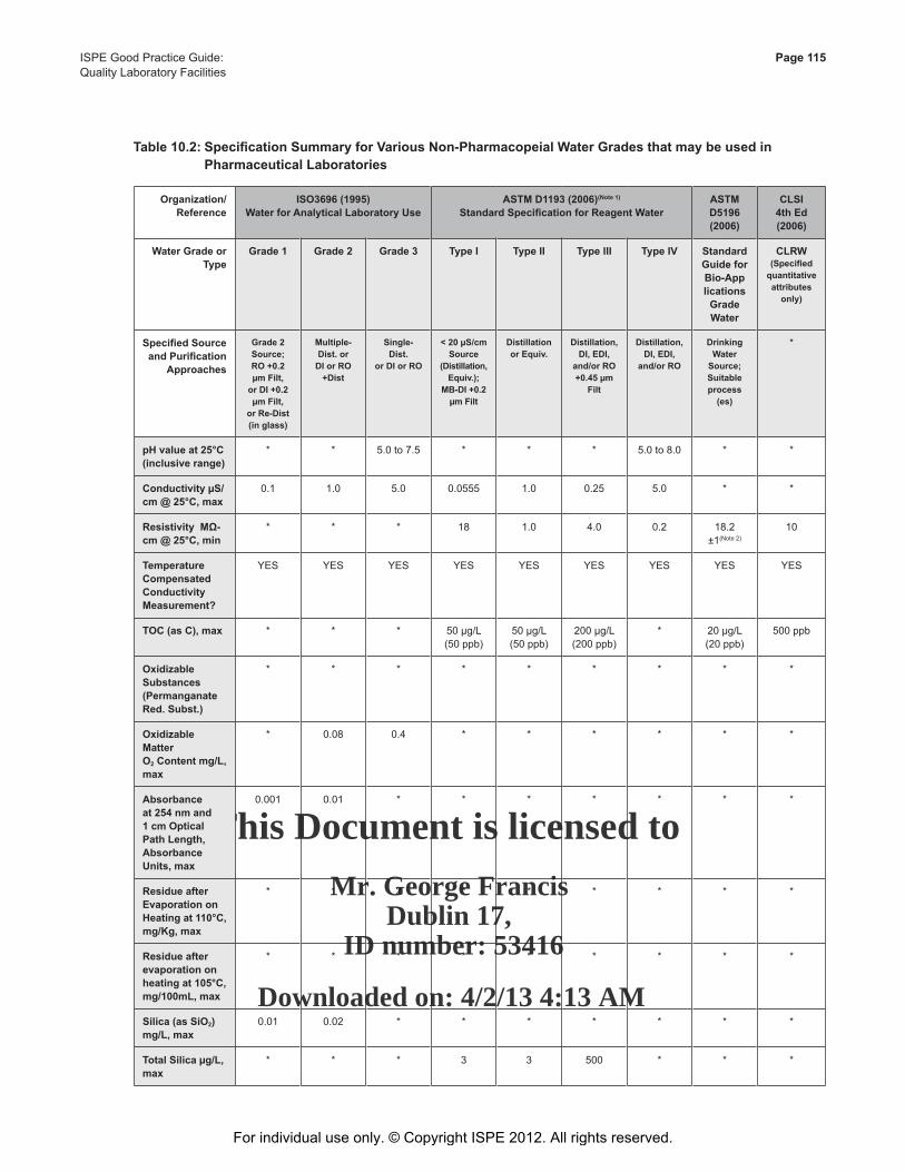
This Document is licensed to
Mr. George FrancisDublin 17,
ID number: 53416
Downloaded on: 4/2/13 4:13 AM
ISPE Good Practice Guide: Page 115Quality Laboratory Facilities
Table10.2:SpecificationSummaryforVariousNon-PharmacopeialWaterGradesthatmaybeusedin PharmaceuticalLaboratories
Organization/Reference
ISO3696(1995)WaterforAnalyticalLaboratoryUse
ASTMD1193(2006)(Note1) StandardSpecificationforReagentWater
ASTM D5196 (2006)
CLSI4thEd(2006)
WaterGradeorType
Grade1 Grade2 Grade3 Type I Type II Type III TypeIV Standard GuideforBio-ApplicationsGradeWater
CLRW (Specifiedquantitativeattributesonly)
SpecifiedSourceandPurification
Approaches
Grade2Source; RO +0.2 µm Filt,
or DI +0.2 µm Filt,
orRe-Dist(inglass)
Multiple-Dist.or
DI or RO +Dist
Single-Dist.
or DI or RO
<20µS/cmSource
(Distillation,Equiv.);
MB-DI+0.2µm Filt
DistillationorEquiv.
Distillation,DI, EDI,
and/orRO+0.45 µm
Filt
Distillation,DI, EDI,
and/orRO
Drinking Water
Source; Suitable process(es)
*
pHvalueat25°C(inclusiverange)
* * 5.0 to 7.5 * * * 5.0 to 8.0 * *
ConductivityµS/cm@25°C,max
0.1 1.0 5.0 0.0555 1.0 0.25 5.0 * *
ResistivityMΩ-cm@25°C,min
* * * 18 1.0 4.0 0.2 18.2 ±1(Note 2)
10
Temperature CompensatedConductivityMeasurement?
YES YES YES YES YES YES YES YES YES
TOC(asC),max * * * 50 µg/L (50 ppb)
50 µg/L (50 ppb)
200 µg/L (200 ppb)
* 20 µg/L (20 ppb)
500 ppb
Oxidizable Substances(Permanganate Red.Subst.)
* * * * * * * * *
Oxidizable Matter O2Contentmg/L,max
* 0.08 0.4 * * * * * *
Absorbanceat 254 nm and 1 cm Optical PathLength,AbsorbanceUnits,max
0.001 0.01 * * * * * * *
ResidueafterEvaporation on Heatingat110°C,mg/Kg,max
* 1 2 * * * * * *
Residueafterevaporation on heatingat105°C,mg/100mL,max
* * * * * * * * *
Silica(asSiO2)mg/L,max
0.01 0.02 * * * * * * *
TotalSilicaµg/L,max
* * * 3 3 500 * * *
For individual use only. © Copyright ISPE 2012. All rights reserved.
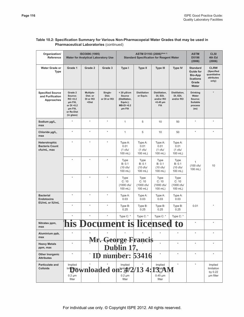
This Document is licensed to
Mr. George FrancisDublin 17,
ID number: 53416
Downloaded on: 4/2/13 4:13 AM
Page 116 ISPE Good Practice Guide: Quality Laboratory Facilities
Table10.2:SpecificationSummaryforVariousNon-PharmacopeialWaterGradesthatmaybeusedin PharmaceuticalLaboratories (continued)
Organization/Reference
ISO3696(1995)WaterforAnalyticalLaboratoryUse
ASTMD1193(2006)(Note1) StandardSpecificationforReagentWater
ASTM D5196 (2006)
CLSI4thEd(2006)
WaterGradeorType
Grade1 Grade2 Grade3 Type I Type II Type III TypeIV Standard GuideforBio-ApplicationsGradeWater
CLRW (Specifiedquantitativeattributesonly)
SpecifiedSourceandPurification
Approaches
Grade2Source; RO +0.2 µm Filt,
or DI +0.2 µm Filt,
orRe-Dist(inglass)
Multiple-Dist.or
DI or RO +Dist
Single-Dist.
or DI or RO
<20µS/cmSource
(Distillation,Equiv.);
MB-DI+0.2µm Filt
DistillationorEquiv.
Distillation,DI, EDI,
and/orRO+0.45 µm
Filt
Distillation,DI, EDI,
and/orRO
Drinking Water
Source; Suitable process(es)
*
Sodiumµg/L,max
* * * 1 5 10 50 * *
Chlorideµg/L,max
* * * 1 5 10 50 * *
HeterotrophicBacteriaCountcfu/mL,max
* * * Type A: 0.01
(1 cfu/100 mL)
Type A: 0.01
(1 cfu/100 mL)
Type A: 0.01
(1 cfu/100 mL)
Type A: 0.01
(1 cfu/100 mL)
1 (100 cfu/100 mL)
10
* * * Type B: 0.1
(10 cfu/100 mL)
Type B: 0.1
(10 cfu/100 mL)
Type B: 0.1
(10 cfu/100 mL)
Type B: 0.1
(10 cfu/100 mL)
* * * Type C: 10
(1000 cfu/100 mL)
Type C: 10
(1000 cfu/100 mL)
Type C: 10
(1000 cfu/100 mL)
Type C: 10
(1000 cfu/100 mL)
BacterialEndotoxinsEU/mLorIU/mL
* * * Type A: 0.03
Type A: 0.03
Type A: 0.03
Type A: 0.03
0.01 ** * * Type B: 0.25
Type B: 0.25
Type B: 0.25
Type B: 0.25
* * * Type C: * Type C: * Type C: * Type C: *
Nitratesppm,max
* * * * * * * * *
Aluminium ppb, max
* * * * * * * * *
HeavyMetalsppm, max
* * * * * * * * *
OtherInorganicAttributes
* * * * * * * * *
Particulate and Colloids
Implied limitation
by 0.2 µm
filter
* * Implied limitation
by 0.2 µm
filter
* Implied limitation
by 0.45 µm
filter
* * Implied limitation by 0.22 µm filter
For individual use only. © Copyright ISPE 2012. All rights reserved.
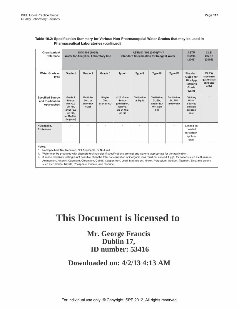
This Document is licensed to
Mr. George FrancisDublin 17,
ID number: 53416
Downloaded on: 4/2/13 4:13 AM
ISPE Good Practice Guide: Page 117Quality Laboratory Facilities
Table10.2:SpecificationSummaryforVariousNon-PharmacopeialWaterGradesthatmaybeusedin PharmaceuticalLaboratories (continued)
Organization/Reference
ISO3696(1995)WaterforAnalyticalLaboratoryUse
ASTMD1193(2006)(Note1) StandardSpecificationforReagentWater
ASTM D5196 (2006)
CLSI4thEd(2006)
WaterGradeorType
Grade1 Grade2 Grade3 Type I Type II Type III TypeIV Standard GuideforBio-ApplicationsGradeWater
CLRW (Specifiedquantitativeattributesonly)
SpecifiedSourceandPurification
Approaches
Grade2Source; RO +0.2 µm Filt,
or DI +0.2 µm Filt,
orRe-Dist(inglass)
Multiple-Dist.or
DI or RO +Dist
Single-Dist.
or DI or RO
<20µS/cmSource
(Distillation,Equiv.);
MB-DI+0.2µm Filt
DistillationorEquiv.
Distillation,DI, EDI,
and/orRO+0.45 µm
Filt
Distillation,DI, EDI,
and/orRO
Drinking Water
Source; Suitable process(es)
*
Nucleases,Proteases
* * * * * * * Limited as needed
for certain applica-
tions
*
Notes:* Not Specified, Not Required, Not Applicable, or No Limit1. Water may be produced with alternate technologies if specifications are met and water is appropriate for the application.2. If in-line resistivity testing is not possible, then the total concentration of inorganic ions must not exceed 1 µg/L for cations such as Aluminum,
Ammonium, Arsenic, Cadmium, Chromium, Cobalt, Copper, Iron, Lead, Magnesium, Nickel, Potassium, Sodium, Titanium, Zinc, and anions such as Chloride, Nitrate, Phosphate, Sulfate, and Fluoride.
For individual use only. © Copyright ISPE 2012. All rights reserved.
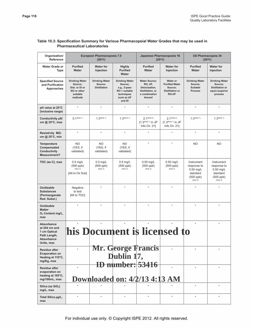
This Document is licensed to
Mr. George FrancisDublin 17,
ID number: 53416
Downloaded on: 4/2/13 4:13 AM
Page 118 ISPE Good Practice Guide: Quality Laboratory Facilities
Table10.3:SpecificationSummaryforVariousPharmacopeialWaterGradesthatmaybeusedin PharmaceuticalLaboratories
Organization/Reference
EuropeanPharmacopoeia7.0(2011)
JapanesePharmacopoeia16(2011)
USPharmacopeia34(2011)
WaterGradeorType
PurifiedWater
WaterforInjection
HighlyPurifiedWater
PurifiedWater
WaterforInjection
PurifiedWater
WaterforInjection
SpecifiedSourceandPurification
Approaches
Drinking Water Source;
Dist.orDIorROorothersuitablemethods
Drinking Water Source;
Distillation
Drinking Water Source;
e.g.,2-passRO+suitabletechniquessuchasUF
and DI
Water Source; RO,UF,
Deionization, Distillation,ora combination
thereof
Water or PurifiedWater
Source; Distillationor
RO-UF
Drinking Water Source; Suitable Process
Drinking Water Source;
Distillationorequiv./superior
process
pHvalueat25°C(inclusiverange)
* * * * * * *
ConductivityµS/cm@25°C,max
5.1(Note 1) 1.3(Note 1) 1.3(Note 1) 2.1(Note 2)
[1.3(Note 1) in JP Info Ch. 21]
2.1(Note 2)
[1.3(Note 1) in JP Info Ch. 21]
1.3(Note 1) 1.3(Note 1)
ResistivityMΩ-cm@25°C,min
* * * * * * *
Temperature CompensatedConductivityMeasurement?
NO(YES, if
validated)
NO(YES, if
validated)
NO(YES, if
validated)
* * NO NO
TOC(asC),max 0.5 mg/L (500 ppb)
(Note 3) [Alt to Ox Sub]
0.5 mg/L (500 ppb)
(Note 3)
0.5 mg/L (500 ppb)
(Note 3)
0.50 mg/L (500 ppb)
(Note 3)
0.50 mg/L (500 ppb)
(Note 3)
Instrument response to 0.50 mg/L standard (500 ppb)
(Note 3)
Instrument response to 0.50 mg/L standard (500 ppb)
(Note 3)
Oxidizable Substances(Permanganate Red.Subst.)
Negative to test
[Alt to TOC]
* * * * * *
Oxidizable Matter O2Contentmg/L,max
* * * * * * *
Absorbanceat 254 nm and 1 cm Optical PathLength,AbsorbanceUnits,max
* * * * * * *
ResidueafterEvaporation on Heatingat110°C,mg/Kg,max
* * * * * * *
Residueafterevaporation on heatingat105°C,mg/100mL,max
* * * * * * *
Silica(asSiO2)mg/L,max
* * * * * * *
TotalSilicaµg/L,max
* * * * * * *
For individual use only. © Copyright ISPE 2012. All rights reserved.
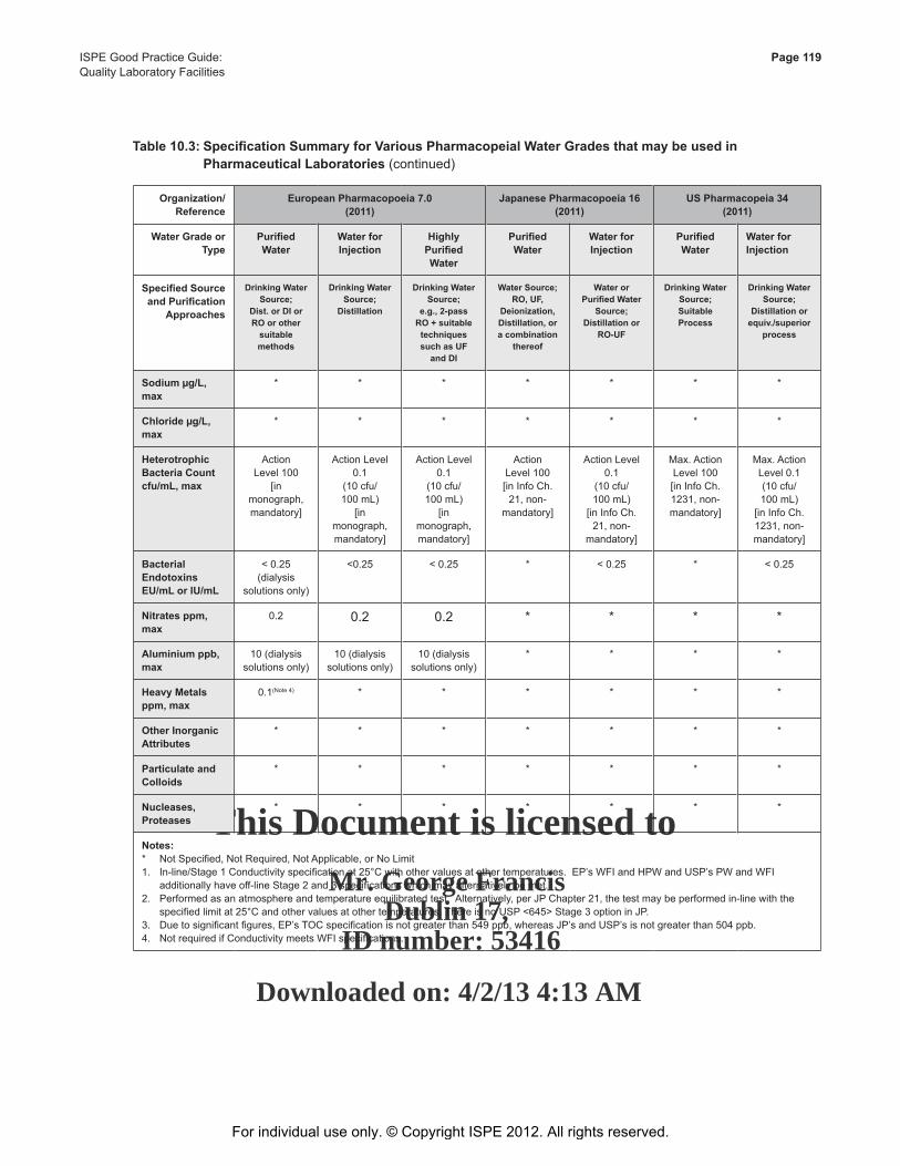
This Document is licensed to
Mr. George FrancisDublin 17,
ID number: 53416
Downloaded on: 4/2/13 4:13 AM
ISPE Good Practice Guide: Page 119Quality Laboratory Facilities
Table10.3:SpecificationSummaryforVariousPharmacopeialWaterGradesthatmaybeusedin PharmaceuticalLaboratories (continued)
Organization/Reference
EuropeanPharmacopoeia7.0(2011)
JapanesePharmacopoeia16(2011)
USPharmacopeia34(2011)
WaterGradeorType
PurifiedWater
WaterforInjection
HighlyPurifiedWater
PurifiedWater
WaterforInjection
PurifiedWater
WaterforInjection
SpecifiedSourceandPurification
Approaches
Drinking Water Source;
Dist.orDIorROorothersuitablemethods
Drinking Water Source;
Distillation
Drinking Water Source;
e.g.,2-passRO+suitabletechniquessuchasUF
and DI
Water Source; RO,UF,
Deionization, Distillation,ora combination
thereof
Water or PurifiedWater
Source; Distillationor
RO-UF
Drinking Water Source; Suitable Process
Drinking Water Source;
Distillationorequiv./superior
process
Sodiumµg/L,max
* * * * * * *
Chlorideµg/L,max
* * * * * * *
HeterotrophicBacteriaCountcfu/mL,max
Action Level 100
[in monograph, mandatory]
Action Level 0.1
(10 cfu/100 mL)
[in monograph, mandatory]
Action Level 0.1
(10 cfu/100 mL)
[in monograph, mandatory]
Action Level 100 [in Info Ch.
21, non-mandatory]
Action Level 0.1
(10 cfu/100 mL)
[in Info Ch. 21, non-
mandatory]
Max. Action Level 100 [in Info Ch. 1231, non-mandatory]
Max. ActionLevel 0.1(10 cfu/100 mL)
[in Info Ch. 1231, non-mandatory]
BacterialEndotoxinsEU/mLorIU/mL
< 0.25 (dialysis
solutions only)
<0.25 < 0.25 * < 0.25 * < 0.25
Nitratesppm,max
0.2 0.2 0.2 * * * *
Aluminium ppb, max
10 (dialysis solutions only)
10 (dialysis solutions only)
10 (dialysis solutions only)
* * * *
HeavyMetalsppm, max
0.1(Note 4) * * * * * *
OtherInorganicAttributes
* * * * * * *
Particulate and Colloids
* * * * * * *
Nucleases,Proteases
* * * * * * *
Notes:* Not Specified, Not Required, Not Applicable, or No Limit1. In-line/Stage 1 Conductivity specification at 25°C with other values at other temperatures. EP’s WFI and HPW and USP’s PW and WFI
additionally have off-line Stage 2 and 3 specifications which may alternatively be met.2. Performed as an atmosphere and temperature equilibrated test. Alternatively, per JP Chapter 21, the test may be performed in-line with the
specified limit at 25°C and other values at other temperatures. There is no USP <645> Stage 3 option in JP.3. Due to significant figures, EP’s TOC specification is not greater than 549 ppb, whereas JP’s and USP’s is not greater than 504 ppb.4. Not required if Conductivity meets WFI specifications.
For individual use only. © Copyright ISPE 2012. All rights reserved.
This Document is licensed to
Mr. George FrancisDublin 17,
ID number: 53416
Downloaded on: 4/2/13 4:13 AM
Page 120 ISPE Good Practice Guide: Quality Laboratory Facilities
The water grades denoted in Tables 10.2 and Table 10.3 frequently do not specify limits for all the groups of impurities. This is particularly marked for the USP [36], EP [37], and JP [38] specifications for grades of pharmaceutical water; such grades may not be appropriate for all laboratory related uses. For water to conform to a particular application, its suitability for the intended use should be verified and the continuation of purity should be ensured.
In addition to their purity specifications, waters which need to meet regulatory requirements may have additional requirements, including:
• Which feed water is to be used
• Limitations on how the water is to be purified
• How and where the purity attributes are to be monitored
• How the monitoring equipment is to be calibrated
• How the purification system performance is to be trended and maintained
Where a particular type of water is specified, e.g., when using an ASTM method, these requirements must be met by the purification system selected.
Where laboratory water quality needs differ from those in manufacturing (e.g., microbiological limits), it may be necessary to establish laboratory water specifications to be met to avoid requiring the laboratory to use water attributes and limits to manufacturing water standards that are not required.
10.2.2.2 Quantity Needs
The water demand profile is needed to size the water generation system(s) and determine if any distribution loops are needed. The water demand/diversity information should include volume delivery information, including maximum demand, batch or continuous delivery needs as well as maximum and average flow rates, the time required to deliver the specified quantity of water, frequency of use or operation, pressure, and temperature. These values should be obtained or estimated in real time, as well as over an operating shift or day.
Normal and worst case water usage profiles should be prepared for 24-hour and 7 day periods. This information, along with diversity of use, dictates the design specification for the system(s).
10.2.2.3 Data Collection
Table 10.4 provides an example table for data collection.
For individual use only. © Copyright ISPE 2012. All rights reserved.
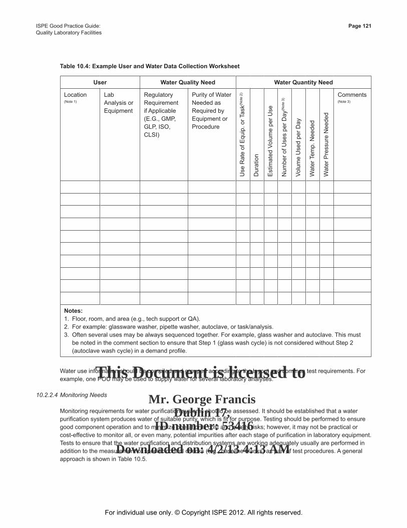
This Document is licensed to
Mr. George FrancisDublin 17,
ID number: 53416
Downloaded on: 4/2/13 4:13 AM
ISPE Good Practice Guide: Page 121Quality Laboratory Facilities
Table10.4:ExampleUserandWaterDataCollectionWorksheet
Water use information should be compiled and grouped according to the layout and common test requirements. For example, one POU may be used to supply water for several laboratory analyses.
10.2.2.4 Monitoring Needs
Monitoring requirements for water purification systems should be assessed. It should be established that a water purification system produces water of suitable purity, which is fit for purpose. Testing should be performed to ensure good component operation and to minimize operational cost and quality risks; however, it may not be practical or cost-effective to monitor all, or even many, potential impurities after each stage of purification in laboratory equipment. Tests to ensure that the water purification and distribution systems are working adequately usually are performed in addition to the measurement of specific control checks (e.g., baseline blanks) as part of test procedures. A general approach is shown in Table 10.5.
User WaterQualityNeed WaterQuantityNeed
Location(Note 1)
Lab Analysis or Equipment
Regulatory Requirement if Applicable (E.G., GMP, GLP, ISO, CLSI)
Purity of Water Needed asRequired by Equipment or Procedure
Use
Rat
e of
Equ
ip. o
r Tas
k(Not
e 2)
Dur
atio
n
Est
imat
ed V
olum
e pe
r Use
Num
ber o
f Use
s pe
r Day
(Not
e 3)
Volu
me
Use
d pe
r Day
Wat
er T
emp.
Nee
ded
Wat
er P
ress
ure
Nee
ded
Comments(Note 3)
Notes:1. Floor, room, and area (e.g., tech support or QA).2. For example: glassware washer, pipette washer, autoclave, or task/analysis.3. Often several uses may be always sequenced together. For example, glass washer and autoclave. This must
be noted in the comment section to ensure that Step 1 (glass wash cycle) is not considered without Step 2 (autoclave wash cycle) in a demand profile.
For individual use only. © Copyright ISPE 2012. All rights reserved.
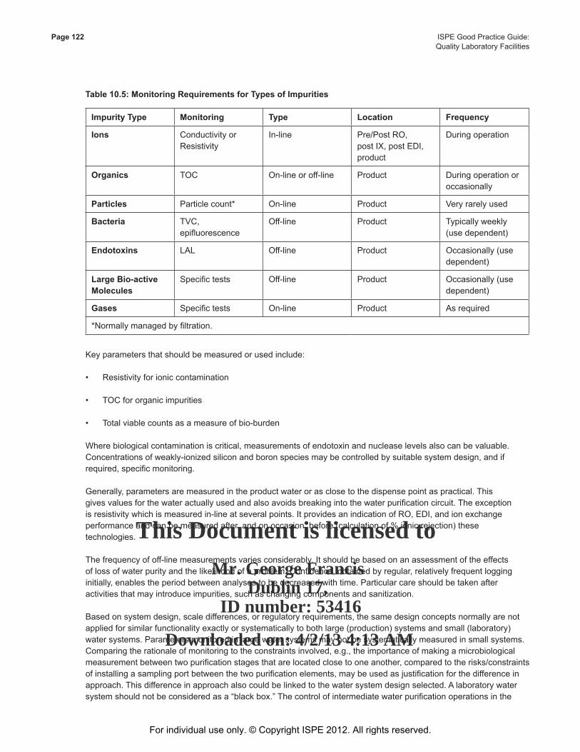
This Document is licensed to
Mr. George FrancisDublin 17,
ID number: 53416
Downloaded on: 4/2/13 4:13 AM
Page 122 ISPE Good Practice Guide: Quality Laboratory Facilities
Table10.5:MonitoringRequirementsforTypesofImpurities
Impurity Type Monitoring Type Location Frequency
Ions Conductivity or Resistivity
In-line Pre/Post RO, post IX, post EDI, product
During operation
Organics TOC On-line or off-line Product During operation or occasionally
Particles Particle count* On-line Product Very rarely used
Bacteria TVC, epifluorescence
Off-line Product Typically weekly (use dependent)
Endotoxins LAL Off-line Product Occasionally (use dependent)
LargeBio-activeMolecules
Specific tests Off-line Product Occasionally (use dependent)
Gases Specific tests On-line Product As required
*Normally managed by filtration.
Key parameters that should be measured or used include: • Resistivity for ionic contamination
• TOC for organic impurities
• Total viable counts as a measure of bio-burden
Where biological contamination is critical, measurements of endotoxin and nuclease levels also can be valuable. Concentrations of weakly-ionized silicon and boron species may be controlled by suitable system design, and if required, specific monitoring.
Generally, parameters are measured in the product water or as close to the dispense point as practical. This gives values for the water actually used and also avoids breaking into the water purification circuit. The exception is resistivity which is measured in-line at several points. It provides an indication of RO, EDI, and ion exchange performance and can be measured after, and on occasion, before (calculation of % ionic rejection) these technologies.
The frequency of off-line measurements varies considerably. It should be based on an assessment of the effects of loss of water purity and the likelihood of a problem. Confidence, obtained by regular, relatively frequent logging initially, enables the period between analyses to be decreased with time. Particular care should be taken after activities that may introduce impurities, such as changing components and sanitization.
Based on system design, scale differences, or regulatory requirements, the same design concepts normally are not applied for similar functionality exactly or systematically to both large (production) systems and small (laboratory) water systems. Parameters monitored in large water systems may not be systematically measured in small systems. Comparing the rationale of monitoring to the constraints involved, e.g., the importance of making a microbiological measurement between two purification stages that are located close to one another, compared to the risks/constraints of installing a sampling port between the two purification elements, may be used as justification for the difference in approach. This difference in approach also could be linked to the water system design selected. A laboratory water system should not be considered as a “black box.” The control of intermediate water purification operations in the
For individual use only. © Copyright ISPE 2012. All rights reserved.
This Document is licensed to
Mr. George FrancisDublin 17,
ID number: 53416
Downloaded on: 4/2/13 4:13 AM
ISPE Good Practice Guide: Page 123Quality Laboratory Facilities
system allows the anticipation of problems, and subsequently improves compliance with good practices; therefore, based on the regulatory requirements, an analysis of the equipment design/content may be required to ensure compliance.
The extent of monitoring required depends on the size and complexity of the system(s).
10.2.2.5 Compliance
Laboratory equipment installed in pharmaceutical laboratories or used for laboratory applications may require compliance with specific regulations including:
• Quality management systems (e.g., Good Laboratory Practices, GMPs)
• Pharmacopeia (e.g., USP [36], EP [37], and JP [38])
• CFRs or local regulations
• Other water standards
Additional regulations also may be requested (e.g., CE, UL marks) as a general organizational policy requirement or for local legal compliance; therefore, it is important to define the list of compliances required to select the final laboratory water solution.
10.2.2.6 Laboratory Environmental Needs
A comprehensive review of all the laboratory work spaces requiring access to laboratory water should be performed to select suitable systems, which meet user requirements, including:
• Quantity of points of use needed
• Location of the different areas needing water and the possibility to group them ,
• Location of the POU (e.g., rooms, elevation, at sinks)
• Use constraints defined by some procedures including:
- Maximum distance to the use location
- Filling large containers
- Large flow rates
• Site-location constraints including:
- Limited access (e.g., cleanroom, off hours use)
- Contaminating atmospheric conditions (e.g., volatile organics, corrosive vapors)
- Noise considerations
- Utilities available (e.g., electricity, source water, drain)
- Space available
For individual use only. © Copyright ISPE 2012. All rights reserved.
This Document is licensed to
Mr. George FrancisDublin 17,
ID number: 53416
Downloaded on: 4/2/13 4:13 AM
Page 124 ISPE Good Practice Guide: Quality Laboratory Facilities
10.2.2.7 Costs
A comprehensive cost analysis that includes the direct and indirect life cycle costs of the proposed laboratory water choice(s) should be developed by the laboratory water owner.
Direct life cycle costs for the system include, e.g.:
• Capital costs including:
- Engineering
- Equipment and material procurement
- Construction/installation
- Commissioning/qualification
• Operating costs including:
- Consumable (e.g., filters)
- Utilities (e.g., water , energy)
- Calibration - Maintenance
- Training
Note: more automated systems may be more expensive to purchase and less expensive to operate.
Indirect costs are an estimate of the potential costs in case of problems. Such an analysis should cover, as a minimum, the costs associated with water quality or quantity problems (e.g., when facing a lack of suitable water during several hours or days).
10.2.3 WaterPurificationTechnologies
There are various combinations of purification technologies with which it is possible to produce the waters that may be required in laboratories. The technologies are similar in type to those used for production purposes, usually on a smaller scale and different in detail. For further information, see the ISPE Water and Steam Systems Baseline® Guide (Second Edition) [39].
10.2.4 LaboratoryWaterSupplyOptions
There are a range of means of providing pure water for laboratory applications. For applications of low volume or which are localized to one area, the choice usually is between a single dedicated water purification system, typically fed from municipal water, and the use of packaged water.
For larger scale installations, a water purification solution can be based on the combination of one or more approach, including:
• A purification system with permanent extensive distribution system to the entire building
• One or more local purification systems with local distribution loop to a floor or laboratory
For individual use only. © Copyright ISPE 2012. All rights reserved.
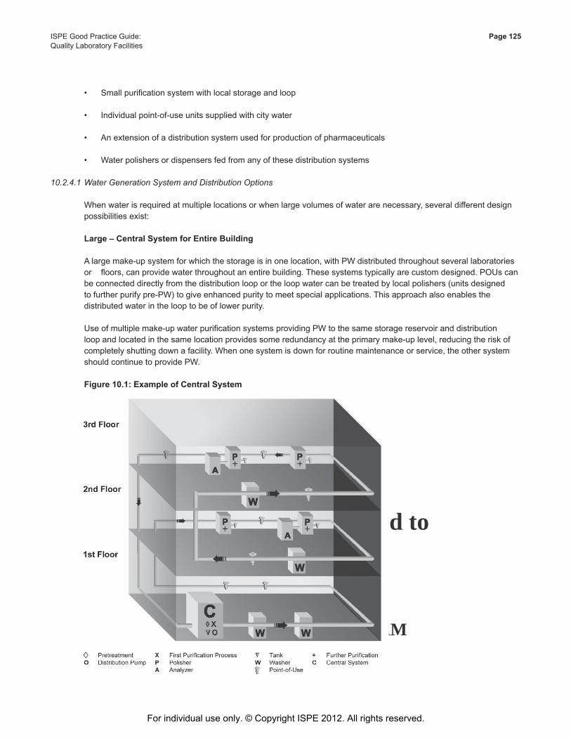
This Document is licensed to
Mr. George FrancisDublin 17,
ID number: 53416
Downloaded on: 4/2/13 4:13 AM
ISPE Good Practice Guide: Page 125Quality Laboratory Facilities
• Small purification system with local storage and loop
• Individual point-of-use units supplied with city water
• An extension of a distribution system used for production of pharmaceuticals
• Water polishers or dispensers fed from any of these distribution systems
10.2.4.1 Water Generation System and Distribution Options
When water is required at multiple locations or when large volumes of water are necessary, several different design possibilities exist:
Large–CentralSystemforEntireBuilding
A large make-up system for which the storage is in one location, with PW distributed throughout several laboratories or floors, can provide water throughout an entire building. These systems typically are custom designed. POUs can be connected directly from the distribution loop or the loop water can be treated by local polishers (units designed to further purify pre-PW) to give enhanced purity to meet special applications. This approach also enables the distributed water in the loop to be of lower purity.
Use of multiple make-up water purification systems providing PW to the same storage reservoir and distribution loop and located in the same location provides some redundancy at the primary make-up level, reducing the risk of completely shutting down a facility. When one system is down for routine maintenance or service, the other system should continue to provide PW.
Figure10.1:ExampleofCentralSystem
For individual use only. © Copyright ISPE 2012. All rights reserved.
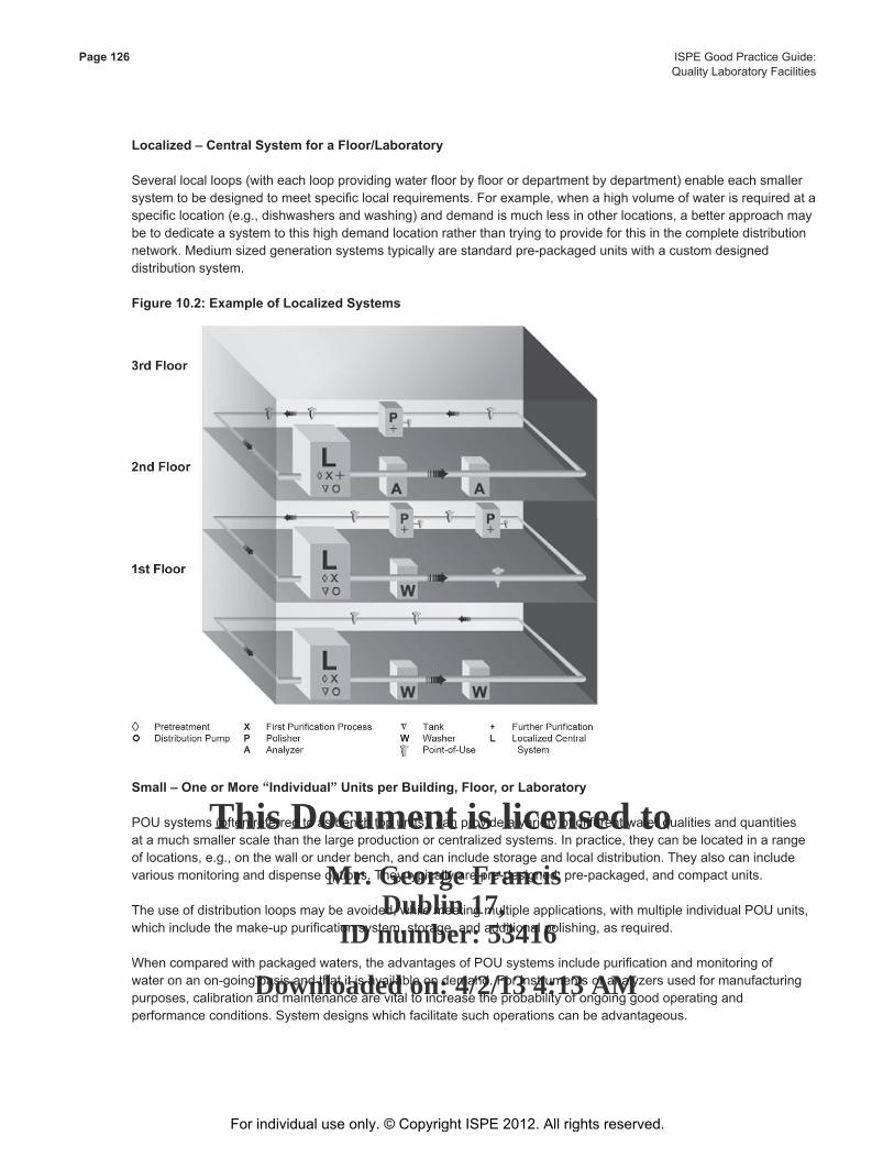
This Document is licensed to
Mr. George FrancisDublin 17,
ID number: 53416
Downloaded on: 4/2/13 4:13 AM
Page 126 ISPE Good Practice Guide: Quality Laboratory Facilities
Localized–CentralSystemforaFloor/Laboratory
Several local loops (with each loop providing water floor by floor or department by department) enable each smaller system to be designed to meet specific local requirements. For example, when a high volume of water is required at a specific location (e.g., dishwashers and washing) and demand is much less in other locations, a better approach may be to dedicate a system to this high demand location rather than trying to provide for this in the complete distribution network. Medium sized generation systems typically are standard pre-packaged units with a custom designed distribution system.
Figure10.2:ExampleofLocalizedSystems
Small–OneorMore“Individual”UnitsperBuilding,Floor,orLaboratory
POU systems (often referred to as bench top units), can provide a variety of different water qualities and quantities at a much smaller scale than the large production or centralized systems. In practice, they can be located in a range of locations, e.g., on the wall or under bench, and can include storage and local distribution. They also can include various monitoring and dispense options. They typically are pre-designed, pre-packaged, and compact units.
The use of distribution loops may be avoided, while meeting multiple applications, with multiple individual POU units, which include the make-up purification system, storage, and additional polishing, as required.
When compared with packaged waters, the advantages of POU systems include purification and monitoring of water on an on-going basis and that it is available on demand. For instruments or analyzers used for manufacturing purposes, calibration and maintenance are vital to increase the probability of ongoing good operating and performance conditions. System designs which facilitate such operations can be advantageous.
For individual use only. © Copyright ISPE 2012. All rights reserved.
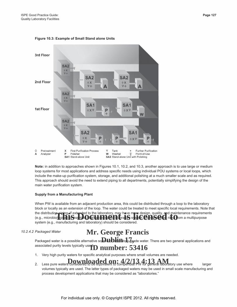
This Document is licensed to
Mr. George FrancisDublin 17,
ID number: 53416
Downloaded on: 4/2/13 4:13 AM
ISPE Good Practice Guide: Page 127Quality Laboratory Facilities
Figure10.3:ExampleofSmallStandaloneUnits
Note: in addition to approaches shown in Figures 10.1, 10.2, and 10.3, another approach is to use large or medium loop systems for most applications and address specific needs using individual POU systems or local loops, which include the make-up purification system, storage, and additional polishing at a much smaller scale and as required. This approach should avoid the need to extend piping to all departments, potentially simplifying the design of the main water purification system.
SupplyfromaManufacturingPlant
When PW is available from an adjacent production area, this could be distributed through a loop to the laboratory block or locally as an extension of the loop. The water could be treated to meet specific local requirements. Note that the distribution piping, if extended to the laboratory, may have more design, quality, and maintenance requirements (e.g., microbiological) to maintain, than a dedicated laboratory system. Contamination risks from a multipurpose system (e.g., manufacturing and laboratory) should be considered.
10.2.4.2 Packaged Water
Packaged water is a possible alternative source of laboratory grade water. There are two general applications and associated purity levels typically used:
1. Very high purity waters for specific analytical purposes where small volumes are needed.
2. Less pure waters considered to be equivalent to compendial PW for general laboratory use where larger volumes typically are used. The latter types of packaged waters may be used in small scale manufacturing and process development applications that may be considered as “laboratories.”
For individual use only. © Copyright ISPE 2012. All rights reserved.
This Document is licensed to
Mr. George FrancisDublin 17,
ID number: 53416
Downloaded on: 4/2/13 4:13 AM
Page 128 ISPE Good Practice Guide: Quality Laboratory Facilities
SimplicityandCostAdvantagesofPackagedLaboratoryWaters
The potential simplicity of using a packaged form of water may seem a more cost effective and suitable option to satisfy a relatively small volume and perhaps a high purity requirement, when considering the capital and operating costs, as well as complexity of designing, installing, qualifying, maintaining, and monitoring a water purification system, regardless of size.
Packaged waters may be purchased in containers of manageable size and packaging configurations that allow their integration into laboratory operations in a similar way to other laboratory reagents, complete with expiration dating, lot numbers, and documentation certifying purity or compliance with standards. Allowed contaminants leaching from the packaging into the water may not be consistent with the implications of the name of the water and this should be considered. A risk assessment may be performed to determine the potential impact of the contaminants on the uses of these waters; therefore, the potential cost and complexity of such risk-based assessments may need to be included in the decision process to assure that the packaged water approach will be acceptable.
Purity
Compendial monographed sterile packaged water purity requirements are defined in the USP with less stringent inorganic specifications and less sensitive organic contaminant tests. The EP and JP also use less sensitive wet chemical tests for these packaged waters. These less stringent specifications allow the presence of organic or inorganic packaging leachables that could exceed the specifications for bulk PW, the minimal purity required by most compendia for pharmacopeial testing. A review and investigation of the purity documentation (Certificate of Analysis or Certificate of Compliance) should be performed to determine if the stated purity (or compliance with compendial specifications) relates to the source water placed into the container, or whether it relates to the guaranteed purity of the water within the container throughout its shelf life.
PW packaging often is plastic or may have elastomeric closures or container entry ports, all of which may leach organic plasticizers, molding releasing agents, or glues and associated solvents and monomers into the water. The organic extractables may become evident with escalating TOC levels over the water’s shelf life. Some elastomers, as well as glass packaging materials, may be prone to leach inorganic ions into the water, degrading its conductivity and pH. Inert packaging materials which usually are used only for special purposes or more costly waters intended for specific analyses such as HPLC, may be an exception.
Packaging leachables are partially controlled by the specifications for the waters (because of selective and broad inorganic limits and a selective organics test insensitive to many extractables). There is potential for variability in the levels of packaging leachables:
• Over the shelf life of different container types
• From supplier to supplier
• Potentially from batch to batch of a given supplier
This potential variability in purity may require risk-based assessments for containers to assure suitability.
If the water’s microbial content is a concern for laboratory applications, any claimed bioburden level by the packaged water’s quality documentation is likely to be a transient attribute, and compromised as soon as the package is opened.
VerificationofSuitabilityofPackagedWaters
If a packaged form of PW is being considered for use in place of bulk PW produced by an on-site water purification system and the purity specifications are not identical, the laboratory should verify fitness for use in each of its applications (e.g., as per USP Chapter <1231> [36]). In-house specifications (e.g., TOC and conductivity) should be
For individual use only. © Copyright ISPE 2012. All rights reserved.
This Document is licensed to
Mr. George FrancisDublin 17,
ID number: 53416
Downloaded on: 4/2/13 4:13 AM
ISPE Good Practice Guide: Page 129Quality Laboratory Facilities
established for these packaged waters, tested on samples taken from representative containers, rather than basing acceptance upon the Certificate of Analysis, to help ensure that unsuitable packaged waters will not be used in susceptible applications.
Suitability verification may not be required if the packaged water is being used for an analysis for which the water was specifically labeled and intended, such as water for HPLC analyses; despite this, such waters may not be suitable for all HPLC analyses. A risk-based approach to assessing overall application suitability is considered appropriate.
As soon as the package is opened and air is allowed to enter the container, the purity starts to degrade. For packaged waters, it is recommended that water from these containers is used for only a short period of time after opening unless, the purity degradation the water will experience has been shown to be inconsequential to its laboratory applications.
If the water required for a given laboratory’s operations is not a compendial grade, but rather a grade specified, e.g., by ASTM, ISO, Clinical and Laboratory Standards Institute (CLSI), or similar organizations, the suitability of packaged forms of these waters for the user application should be verified, unless certified for a specific purpose by the manufacturer of the packaged water. In addition, because some of these water grades have microbial and endotoxin specifications in addition to their chemical specifications, consideration should be given to the potential negative impact on these attributes from how water is removed from the package and by how long the opened package is kept in use.
BalanceofCostandSuitability
Packaged waters may be appropriate in laboratories, particularly where there is a need for a minimal amount for specific compatible applications. Where water is more generally needed for analytical applications, the risks and cost of assuring suitability for each application, potentially for each new batch or shipment received, should be balanced against the cost of installing and maintaining a purification system to produce bulk water, the application suitability for which may be related directly to ongoing quality monitoring.
10.2.4.3 Related Considerations
QuantityNeeds
Large distribution configurations usually are considered when PW is required at different locations or in large volumes. It may be practical to meet high local flow or pressure requirements by additional local pumps and reservoirs, even with a large distribution system.
The distribution design should maintain water quality provided by a centralized system. The general advantages and limitations, described in the ISPE Baseline® Guide Water and Steam Systems (Second Edition) [39], for the different distribution configurations (loop, etc.) could be directly applied for the selection of the distribution configuration used in a laboratory.
QualityNeeds
In general, a large system should be considered when an equivalent water quality is required in a variety of locations. Specific higher water purity requirements can be accounted for by individual polishing equipment. As the number of different water qualities required in an area increases, so does the importance of individual POU systems to account for specific needs. Several local distribution systems may be more effective in meeting diverse water purity requirements, if they can be localized.
Designing a large system that will produce water based on the most stringent water purity application requirements, may be an alternative approach; however, this solution is considered unlikely to balance the advantages and limitations (costs, complexity of maintaining high water quality in a distribution system). As the length of the distribution increases, the greater the difficulty in maintaining the equivalent levels of quality at all points, and the greater the risk of contamination (particularly bacteriological). The distribution design, materials in contact with the water and components installed, etc., can affect differences in quality significantly.
For individual use only. © Copyright ISPE 2012. All rights reserved.
This Document is licensed to
Mr. George FrancisDublin 17,
ID number: 53416
Downloaded on: 4/2/13 4:13 AM
Page 130 ISPE Good Practice Guide: Quality Laboratory Facilities
MonitoringandComplianceNeeds
The greater the degree of equipment centralization, the more monitoring controls are localized. Time spent on checking/controlling satisfactory equipment operation (when compared with individual POU systems); may be optimized by localization; however, providing monitoring information to users (quality parameters, etc.) may be important. In a centralized configuration, the installation and associated costs of remote control/alert or individual monitoring equipment at the points where such information may be important should be considered.
A system that will distribute water to different locations with different regulatory requirements should align the main part of the installation requirements (design, equipment selection, maintenance program, etc.) to the most stringent regulatory requirements.
EnvironmentalConstraints
The overall laboratory architecture and that of the various departments and floors in a building should be analyzed. If a single large system is chosen, its distribution should comply with typical design practices (see the Water and Steam Systems Baseline® Guide (Second Edition) [39]) and it should be verified that successful installation is possible (wall supports, etc.). The total length and height between the lower and upper distribution points will have a significant impact on the final distribution design, and on whether the water quantity and quality can be delivered consistently as requested. If large-scale storage and distribution are considered for an existing building, the available architecture (door openings) should be able to accommodate integration of the solution (storage, etc.). Exposed distribution system pipework can provide needed flexibility for distribution system modifications. The noise level should be taken into consideration when choosing the location where a water system will be installed, as equipment delivering large volumes of PW is in general noisier than standard laboratory equipment. These factors should be studied when a new construction is planned.
Space available within the laboratory may be restricted. Distribution equipment and local units will use bench/wall space, or storage space if located under-bench. Placement of these alternatives should be considered.
MaintenanceNeeds
In a single main installation, the advantage of having less systems to maintain may be offset by the complexity of the installation and the distribution system. A trained technician may need to be available to deal with issues in a timely fashion. The risks of problems usually increase with the complexity and length of the distribution; therefore, more frequent maintenance may be required, and depending on the configuration selected, this may affect laboratory operations.
RiskManagement
The consequences of a lack of water caused by preventive or corrective maintenance should be analyzed and compared to the user requirements at the laboratory, departmental, and floor levels. A sanitization or a repair of the distribution system will not have the same consequences if the installation is a centralized system and distribution is for the entire building, rather than for a department or a laboratory. A duplex (multiple) approach minimizes the risk of interruption of water supply; however, it adds additional costs and is limited to cover the problems linked to the make-up system. Distribution complexity, length, operating conditions (pressure, temperature, equipment, etc.) will be directly related to risk management and should be considered before making the final configuration decision. For example, horizontal distribution (one floor) compared to vertical distribution (over several floors) will minimize pressure-drop related issues and optimize the linear velocity of water in the pipes.
Users’Convenience
The location and quantity of the PW POUs may depend upon user requirements such as:
• The time spent to get water
For individual use only. © Copyright ISPE 2012. All rights reserved.
This Document is licensed to
Mr. George FrancisDublin 17,
ID number: 53416
Downloaded on: 4/2/13 4:13 AM
ISPE Good Practice Guide: Page 131Quality Laboratory Facilities
• Frequency at which water is require
• The risks associated with a decrease in water quality during transportation
The final solution proposed should take into consideration the potential water purities required and provide an optimized way of providing users with water of the appropriate quality.
FutureLaboratoryExpansionorModifications
Information on future modifications of the installation should be considered when making final design/configuration selections. As distribution complexity increases, so does the level of risk, difficulty, and expense associated with changes to the laboratory’s distribution to serve future needs. The possible need to perform a revalidation could add complexity and cost. Smaller size production units also allow an easier renewal program, as the investment can be planned over several years, renewing one smaller installation at a time.
Costs
The total costs equal the combination of the capital investment, operating, and risk management costs. In addition to these total costs, the financial investment strategy of the organization (high capital – low operating
costs) will have an impact on the final decision.
Initial investment will depend on site specific factors; in general, local systems are likely to be less expensive if there are few users who are widely distributed and with disparate water requirements. A large or medium distributed system is likely to be more cost-effective for large volume usage of a similar water quality within one building.
Comparison
The final choice should be the result of an analysis based on the advantages and disadvantages of the various configurations in regard to the quantities and qualities of water required, geographic distribution of these requirements, budget, etc.
Establishing these needs is critical. The strengths and weaknesses of the various configurations are summarized in Table 10.6. These comments are for guidance only as other factors may drive the final choice.
Table 10.6 provides a comparison of the advantages and limitations of various system design options, which provides an overview of which factors should be considered when going through the selection process.
For individual use only. © Copyright ISPE 2012. All rights reserved.
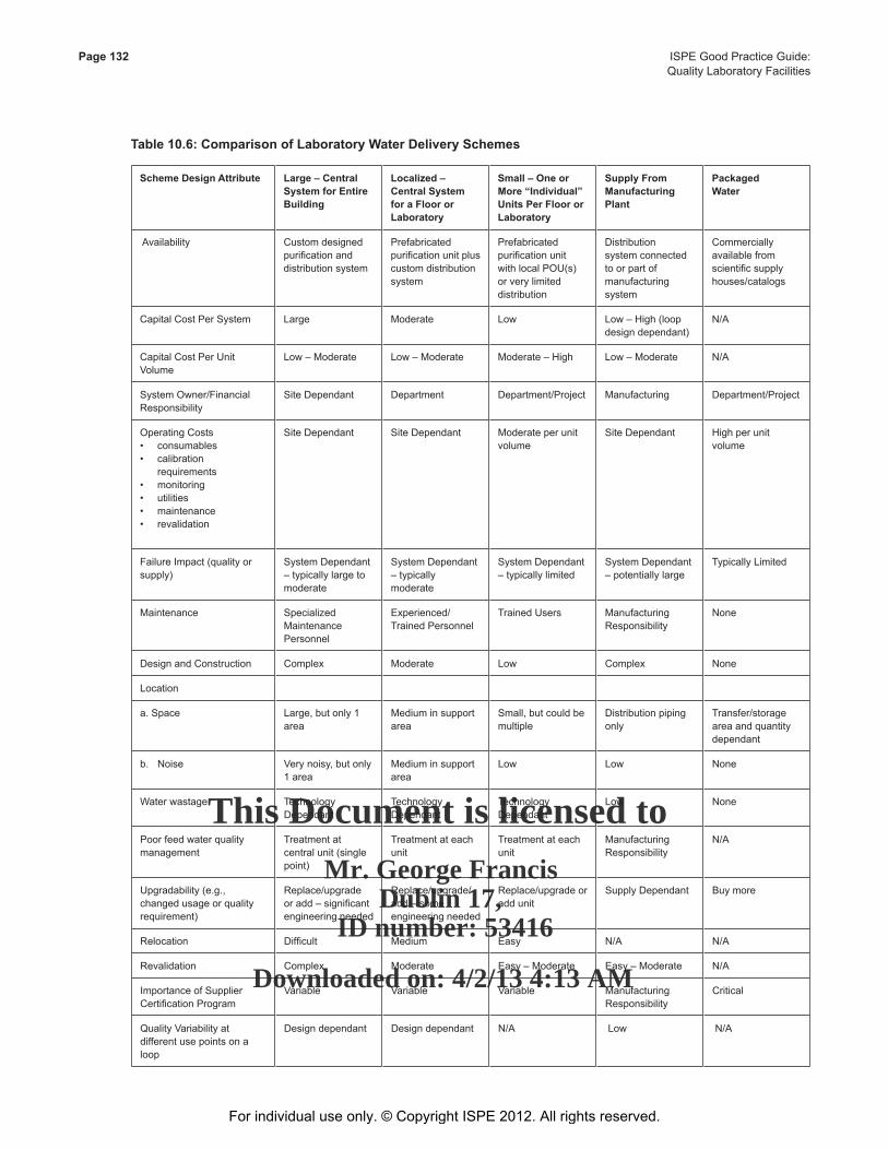
This Document is licensed to
Mr. George FrancisDublin 17,
ID number: 53416
Downloaded on: 4/2/13 4:13 AM
Page 132 ISPE Good Practice Guide: Quality Laboratory Facilities
Table10.6:ComparisonofLaboratoryWaterDeliverySchemes
SchemeDesignAttribute Large–CentralSystemforEntireBuilding
Localized – CentralSystemforaFloororLaboratory
Small – One or More “Individual” UnitsPerFloororLaboratory
Supply From ManufacturingPlant
Packaged Water
Availability Custom designed purification and distribution system
Prefabricated purification unit plus custom distribution system
Prefabricated purification unit with local POU(s) or very limited distribution
Distribution system connected to or part of manufacturing system
Commercially available from scientific supply houses/catalogs
Capital Cost Per System Large Moderate Low Low – High (loop design dependant)
N/A
Capital Cost Per Unit Volume
Low – Moderate Low – Moderate Moderate – High Low – Moderate N/A
System Owner/Financial Responsibility
Site Dependant Department Department/Project Manufacturing Department/Project
Operating Costs• consumables• calibration requirements• monitoring• utilities• maintenance• revalidation
Site Dependant Site Dependant Moderate per unit volume
Site Dependant High per unit volume
Failure Impact (quality or supply)
System Dependant – typically large to moderate
System Dependant – typically moderate
System Dependant – typically limited
System Dependant – potentially large
Typically Limited
Maintenance Specialized Maintenance Personnel
Experienced/Trained Personnel
Trained Users Manufacturing Responsibility
None
Design and Construction Complex Moderate Low Complex None
Location
a. Space Large, but only 1 area
Medium in support area
Small, but could be multiple
Distribution piping only
Transfer/storage area and quantity dependant
b. Noise Very noisy, but only 1 area
Medium in support area
Low Low None
Water wastage Technology Dependant
Technology Dependant
Technology Dependant
Low None
Poor feed water quality management
Treatment at central unit (single point)
Treatment at each unit
Treatment at each unit
Manufacturing Responsibility
N/A
Upgradability (e.g., changed usage or quality requirement)
Replace/upgrade or add – significant engineering needed
Replace/upgrade/add – some engineering needed
Replace/upgrade or add unit
Supply Dependant Buy more
Relocation Difficult Medium Easy N/A N/A
Revalidation Complex Moderate Easy – Moderate Easy – Moderate N/A
Importance of Supplier Certification Program
Variable Variable Variable Manufacturing Responsibility
Critical
Quality Variability at different use points on a loop
Design dependant Design dependant N/A Low N/A
For individual use only. © Copyright ISPE 2012. All rights reserved.
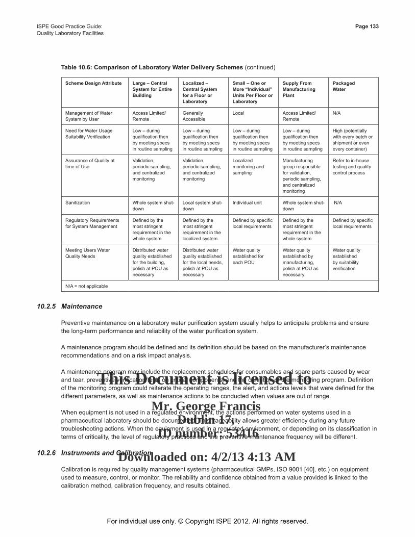
This Document is licensed to
Mr. George FrancisDublin 17,
ID number: 53416
Downloaded on: 4/2/13 4:13 AM
ISPE Good Practice Guide: Page 133Quality Laboratory Facilities
Table10.6:ComparisonofLaboratoryWaterDeliverySchemes(continued)
SchemeDesignAttribute Large–CentralSystemforEntireBuilding
Localized – CentralSystemforaFloororLaboratory
Small – One or More “Individual” UnitsPerFloororLaboratory
Supply From ManufacturingPlant
Packaged Water
Management of Water System by User
Access Limited/Remote
Generally Accessible
Local Access Limited/Remote
N/A
Need for Water Usage Suitability Verification
Low – during qualification then by meeting specs in routine sampling
Low – during qualification then by meeting specs in routine sampling
Low – during qualification then by meeting specs in routine sampling
Low – during qualification then by meeting specs in routine sampling
High (potentially with every batch or shipment or even every container)
Assurance of Quality at time of Use
Validation, periodic sampling, and centralized monitoring
Validation, periodic sampling, and centralized monitoring
Localized monitoring and sampling
Manufacturing group responsible for validation, periodic sampling, and centralized monitoring
Refer to in-house testing and quality control process
Sanitization Whole system shut-down
Local system shut-down
Individual unit Whole system shut-down
N/A
Regulatory Requirements for System Management
Defined by the most stringent requirement in the whole system
Defined by the most stringent requirement in the localized system
Defined by specific local requirements
Defined by the most stringent requirement in the whole system
Defined by specific local requirements
Meeting Users Water Quality Needs
Distributed water quality established for the building, polish at POU as necessary
Distributed water quality established for the local needs, polish at POU as necessary
Water quality established for each POU
Water quality established by manufacturing, polish at POU as necessary
Water quality established by suitability verification
N/A = not applicable
10.2.5 Maintenance
Preventive maintenance on a laboratory water purification system usually helps to anticipate problems and ensure the long-term performance and reliability of the water purification system.
A maintenance program should be defined and its definition should be based on the manufacturer’s maintenance recommendations and on a risk impact analysis.
A maintenance program may include the replacement schedules for consumables and spare parts caused by wear and tear, preventive verification/tests on critical components, and the definition of the monitoring program. Definition of the monitoring program could reiterate the operating ranges, the alert, and actions levels that were defined for the different parameters, as well as maintenance actions to be conducted when values are out of range.
When equipment is not used in a regulated environment, the actions performed on water systems used in a pharmaceutical laboratory should be documented. This traceability allows greater efficiency during any future troubleshooting actions. When the equipment is used in a regulated environment, or depending on its classification in terms of criticality, the level of regulatory practices and the preventive maintenance frequency will be different.
10.2.6 InstrumentsandCalibration
Calibration is required by quality management systems (pharmaceutical GMPs, ISO 9001 [40], etc.) on equipment used to measure, control, or monitor. The reliability and confidence obtained from a value provided is linked to the calibration method, calibration frequency, and results obtained.
For individual use only. © Copyright ISPE 2012. All rights reserved.
This Document is licensed to
Mr. George FrancisDublin 17,
ID number: 53416
Downloaded on: 4/2/13 4:13 AM
Page 134 ISPE Good Practice Guide: Quality Laboratory Facilities
The measurement of quality parameters, e.g., conductivity, TOC, and bacteria, after each purification step, may not be relevant in a laboratory water system when the distances between two purification stages are minimized and the risks of contamination through insertion of “sanitary” sampling instruments may be higher than the anticipated benefits. The measurement of water quality and operating parameters after major water purification steps in a laboratory water system may help to anticipate operating and performance problems.
Frequency of calibration should be based on the type of measurement performed (e.g., temperature, conductivity, TOC, pressure), the type of instruments used (method, model, etc.), and the importance of the measurement for the application, in addition to the importance of the application in the entire process. The frequency should be defined following a risk impact analysis approach.
10.2.7 CommissioningandQualification
Commissioning and qualification of water systems are discussed in Chapter 11 of this Guide. The same qualification approach should be followed for laboratory water systems should be qualified using equivalent approaches to those for the manufacturing systems.
If the laboratory water system is an extension of a manufacturing distribution loop into the laboratory area, the issues and testing that apply to the validation of the water system for manufacturing also apply to the POUs in the laboratory area.
Where the water system is exclusively for laboratory use, the specific purity attributes required in the laboratory may differ from those required for water used for manufacturing. These laboratory purity differences (or impurity allowances) may be reflected in the use of different or considerably scaled down purification unit operations, and different system materials, distribution system designs, and POU valve types than are typically present in manufacturing water systems.
Small, tightly packaged bench-top or wall-mounted water purification units may be designed to operate to the point of reduced quality (e.g., exhaustion) from one or more purification modules; the point of reduced quality usually is signaled by a built-in sensor. There is a risk of producing and using unacceptable water associated with these types of laboratory water system designs; maintenance approaches should be evaluated prior to system selection and purchase, and challenged or verified during qualification. The high number of purity attribute, operational, maintenance, and design differences between manufacturing and laboratory water systems usually requires the strategy for the qualification process for laboratory water systems to differ from that typically used for manufacturing water systems.
10.2.7.1 ImportanceofInternalLaboratoryWaterSpecificationStandards
The minimum chemical purity of water normally required for analytical purposes is compendial PW. A pharmaceutical laboratory PW system may not require a microbial specification, because only the water’s chemical purity is of consequence to a number of laboratory uses.
Where the water purity attributes required from a laboratory water system differ from the purity attributes needed by and described by an organization’s raw material standards or monographs for manufacturing PW or water for injection(s) systems, separate specifications to define laboratory water quality should be developed. These specifications may be the basis for the acceptance criteria for water system qualification processes; documented standards for the quality of waters needed in the laboratory should be defined. Where these standards are not defined, the laboratory may be required to apply water attributes and limits from manufacturing water standards. The manufacturing water attributes and limits may be unnecessary or not sufficiently stringent and for which the laboratory water systems may not have been designed to control these appropriately.
For individual use only. © Copyright ISPE 2012. All rights reserved.
This Document is licensed to
Mr. George FrancisDublin 17,
ID number: 53416
Downloaded on: 4/2/13 4:13 AM
ISPE Good Practice Guide: Page 135Quality Laboratory Facilities
10.2.7.2TailoringLaboratoryWaterSystemQualificationtoIntendedSystemCapability
Large laboratory water systems may be entirely custom designed and built. These systems can be designed to include special monitoring and sampling capability between unit operations.
For medium to smaller sized laboratory water systems, smaller purification units with preconfigured unit operations usually are obtained as a single unit. These preconfigured units may provide less opportunity for sampling between modules for monitoring individual unit operations.
Requirements to verify the performance of individual unit operations should be determined based on the overall system design and quality needs. Retrofitting sampling capabilities for qualification purposes to prefabricated systems may not be feasible, as they often are compact, “well-tuned” systems.
Smaller bench-top or wall-mounted single POU systems also may have limited user access to on-board gauges and instruments for calibration and standardization purposes.
Where gauges and instruments are for informational purposes only (e.g., to signal performance changes in the system), and definitive QC testing is performed either off-line (with occasional grab samples) or by portable in/at/on-line instruments that can be calibrated/standardized, then lack of access may not be a problem. Where the on-board gauges and instruments are intended for QC purposes, then user accessibility, the ability to calibrate, and pharmacopeial compliance of instrument features are considered more significant. Therefore, such capability should be investigated during the water system selection process in order to ensure compliance with user and regulatory needs.
A systematic duplication of the qualification approach used for manufacturing water system designs may not be appropriate for laboratory water systems. The duration of the qualification process, which includes the PQ, should be customized for the evaluation of the laboratory water quality attributes and the nature of the water system’s operation. For example, if there are no microbial attributes of concern for the laboratory water, the only impact of biofilm development would be to reduce the longevity or efficiency of chemical purification unit operations. This would be apparent in the chemical quality of the effluent water. Without microbial attributes of concern in the final water, the period of qualification and frequency of sampling may be tailored to evaluate the consistency of the chemical purification processes. However, if the unit operations are not intended to be periodically replaced because of exhaustion, such as RO modules, periodic microbial monitoring may be of operational value, rather than being a quality requirement per se.
The qualification of a laboratory water system may be more limited (or more stringent) than that for a manufacturing water system, and the protocols should be developed to accommodate those differences, as long as the total qualification process reveals the operational consistency of the water system for controlling the quality attributes of concern. If a specific water system monitoring feature or a particular quality attribute is an absolute requirement for an organization’s water system validation program, a laboratory water system that contains those features and is able to control the mandated purity attributes should be purchased and installed.
10.2.7.3 Special Validation Considerations for Small Laboratory Systems
ConductivityComplianceandConsistency
Most small water purification units, especially the compact, prefabricated, single POU systems, contain an on-board conductivity/resistivity instrument with its sensor positioned within the finished water stream. If the purification unit has been in a “stand-by” mode, system manuals often instruct the user to initially recirculate the water through the unit or flush water to drain until the conductivity/resistivity reading gives acceptable values. If that instrument can be calibrated and complies with the compendial requirements, the readings can be evaluated against those compendial specifications. If, however, the instrument cannot be calibrated or otherwise does not meet compendial requirements, it can still be used as an informational instrument whose performance should be periodically compared or correlated to an instrument that does meet compendial requirements through the in-line testing of the same water. The
For individual use only. © Copyright ISPE 2012. All rights reserved.
This Document is licensed to
Mr. George FrancisDublin 17,
ID number: 53416
Downloaded on: 4/2/13 4:13 AM
Page 136 ISPE Good Practice Guide: Quality Laboratory Facilities
relationship of those data correlations can then impart a level of confidence to the informational instrument readings for day-to-day operations. Since the on-board instrument is only an informational instrument, periodic testing on water from the system using a compliant instrument is needed to assure ongoing compendial compliance. Whenever, the product water does not meet those conductivity specifications after appropriate recirculation or flushing to drain, it is usually a sign that a purification module within the unit should be replaced. After such a replacement has been executed, the water generally resumes conformance with the conductivity specifications. Having procedures in place to assure proper use of the water system with appropriate precautions to preclude using unacceptable water is very important. Verifying that this exhaustion/module replacement/use resumption phenomenon reproducibly occurs also can be an element of the system’s qualification.
TOCComplianceandConsistency
It is not universal for such compact, prefabricated purification units to contain on/at-line TOC monitoring. For those that do not have built in TOC monitoring capability, the TOC test for such systems should be performed either on grab samples from the system or by connection, often at a use point, to a TOC instrument. The TOC purification capability of such a system is an attribute that could, like conductivity, change dramatically in a short period of time because of the way this purification equipment may be operated with ionic exhaustion usually signaling a need for reactive maintenance. Without on/at-line TOC monitoring it is impractical to determine TOC with every use, unlike what is usually possible with in-line conductivity. The consistency of TOC concentrations is important to validate, not only during routine use up to the point of potential TOC removal exhaustion, but also immediately after any purification module replacement when TOC spikes are not uncommon. Therefore, the duration of frequent grab sample or on/at-line TOC monitoring during qualification needs to at least encompass a period long enough to verify the predictability of TOC removal exhaustion, which may occur either before or after ionic exhaustion. In addition, after a specified long idle period between system uses, the point in time after pre-use flushing or polishing recirculation when the monitored conductivity signals that the water is ionically acceptable for use, also should be verified as attaining acceptable TOC quality.
ConsistencyofOtherAttributes
This same approach as used for TOC should be applied to any quality attribute defined as important and not routinely monitored with every use. This attribute performance characterization could then be incorporated into usage and maintenance SOPs for the system (which may be different from those recommended by the purification unit manufacturer) that would preclude unwittingly making and using unacceptable quality laboratory water. The qualification process could then verify that these other attributes, though infrequently routinely tested, are consistently met when the system is operated appropriately.
10.3 AdditionalProgrammingConsiderations
RoadandParkingModifications:
• Parking lot expansion/parking spaces needed
• Contractor’s gated opening, roadway and parking area
• Logistics plan for contractor lay down and temporary site offices/trailers
• Facility ring road consideration
• Security buffer from either known or unknown risks
• Cafeteria access for deliveries and waste removal
• Lighting and storm drainage
For individual use only. © Copyright ISPE 2012. All rights reserved.
This Document is licensed to
Mr. George FrancisDublin 17,
ID number: 53416
Downloaded on: 4/2/13 4:13 AM
ISPE Good Practice Guide: Page 137Quality Laboratory Facilities
SecurityRequirements:
• Guard house, site security
• Access control card key/other.
• Fencing
• Access pedestrian, employee, services.
• Lighting/power
• Phone/data
SiteModificationsforExpansion:
• Grading and tree removal
• Storm water and site drainage
• Landscaping consistent with the existing plant design
• Temporary trailers equipped with appropriate field office cubicles
Fire Protection:
• Water tank
• Loop extension, permitted pressure drop
Power:
• Existing substation
• New substation
• Emergency (existing capacity or new capability)
ChilledWater:
• Existing capacity or new
Steam:
• Existing capacity or new
• Pure Steam (Clean Steam), e.g., for autoclaves
CompressedAir:
• Existing capacity or new
For individual use only. © Copyright ISPE 2012. All rights reserved.
This Document is licensed to
Mr. George FrancisDublin 17,
ID number: 53416
Downloaded on: 4/2/13 4:13 AM
Page 138 ISPE Good Practice Guide: Quality Laboratory Facilities
Gases:
The list of gases in the requisite purity used by a quality laboratory usually depends on the range of instruments used. Examples include:
• Hydrogen
• Helium
• Nitrogen (Note: mass spectrometer min. 6 bar, (87 psi) high requirement for purity (vaporizer))
• Argon
• Oxygen
• Carbon dioxide
• Synthetic air
A central carbon dioxide supply (incubation cabinets) should be considered. For gases supplied from a central system consideration should be given to:
• Existing or new capacity
• Truck access
• Distribution upgrade to meet the laboratory needs
For further information, see the ISPE Good Practice Guide: Process Gases [31].
Sewer:
• Existing capacity or new
BuildingAutomationSystem:
• New or existing BAS and utility monitoring system
• Networking needs for new laboratory facility
Cafeteria:
• Expansion to accommodate new head count
WasteRoom:
• Dumpster requirements
• Permitting
• Hazardous waste storage facility for flammable materials built in accordance with the National Electric Code governing the storage of flammable hazardous waste or other appropriate local codes
For individual use only. © Copyright ISPE 2012. All rights reserved.
This Document is licensed to
Mr. George FrancisDublin 17,
ID number: 53416
Downloaded on: 4/2/13 4:13 AM
ISPE Good Practice Guide: Page 139Quality Laboratory Facilities
InformationSystems:
• Computer room space to meet expansion needs
• Expand/replace computer hardware to meet planned increase in transactions
• Modify computer software to handle planned increase in transactions
• Modify existing computer software to meet changes to business procedures
• Obtain software licenses to handle increased number of users
• Hardware/software to meet workstation needs of additional head count
• Expand/replace network infrastructure to handle expansion needs
• Document all changes and provide space for related documentation
• Validate changes according to system life cycle
• Provide necessary resources to complete expansion tasks related to information systems
10.4 UtilityandSupportSpaces
The quality laboratory is programmed with its associated support spaces such as a solvent storage room, stockroom, glass wash room, scientific write up spaces, and laboratory management offices. Additionally, consideration should be given to janitor’s closets, closets for analyst’s smocks, general storage, and a room for effluent transfer and disposal.
Spaces associated with telephone, data, and specialty services requiring closet support space should be programmed into the design. The specialty requirement for power, emergency power, and cooling should be considered.
Consideration should be given to spaces allowing laboratory adaptability to accommodate change. Support spaces need to be generous enough so that physical and infrastructure changes can be accomplished. These spaces should not be customized to meet an immediate need. Services distributed to the laboratory should be run overhead or in an interstitial space. Adequate space should be provided allowing maintenance and repair without interruption of laboratory operations.
For individual use only. © Copyright ISPE 2012. All rights reserved.

This Document is licensed to
Mr. George FrancisDublin 17,
ID number: 53416
Downloaded on: 4/2/13 4:13 AM
For individual use only. © Copyright ISPE 2012. All rights reserved.
This Document is licensed to
Mr. George FrancisDublin 17,
ID number: 53416
Downloaded on: 4/2/13 4:13 AM
ISPE Good Practice Guide: Page 141Quality Laboratory Facilities
11 Commissioning and Qualification11.1 Introduction
It is the intent of all regulatory agencies to verify that manufacturers’ reduce and control risk to product quality and patient safety. To meet these expectations, industry has developed a methodology to produce documented evidence that facilities are built to design specifications and that equipment and systems are installed correctly and operate in accordance with the specifications.
Commissioning should be performed by appropriate experts who will safely set configure equipment and systems to ensure that:
• Start-up and shutdown occur in the proper sequence
• Alarms are generated in accordance with the specifications
• Generated data is accurate
• The equipment or system operates as specified Qualification leverages commissioning to provide documented evidence that equipment and systems meet
acceptance criteria for critical aspects identified by risk assessment or regulatory requirements.
In August of 2007, the American Society for Testing and Materials (ASTM) published a new standard titled “A Standard Guide for Specification, Design and Verification of Biopharmaceutical Manufacturing Systems and Equipment,” designated E2500-07 [24]. This Guide is based on a risk management and process knowledge approach to the specification, design, and verification of equipment and systems that could affect product quality and patient safety. Under section 1.3 of this Guide, it clearly states it may be applied to laboratories and associated equipment and information systems. In the standard, commissioning and qualification are an approach to verifying systems are “fit for intended use, have been properly installed, and are operating correctly.” ISPE’s Guide: Science and Risk-Based Approach for the Delivery of Facilities, Systems, and Equipment [29] reflects the principles and practices outlined in this standard. Similarly, this Chapter of the Quality Laboratory Guide promotes the use of ASTM standard E2500 [24] to verify that a laboratory facility is “fit for use.”
Additional guidance documents that are relevant to commissioning and qualification of laboratory facilities that should be referenced include:
• ICH Q8 Pharmaceutical Development [41]
• ICH Q9 Quality Risk Management [27]
Other ISPE Guides relevant to commissioning and qualification of laboratory facilities should be referenced as necessary and include:
• ISPE Baseline® Guide: Water and Steam Systems (Second Edition) [39]
• ISPE Good Practice Guide: Maintenance [32]
• ISPE GAMP® 5: A Risk-Based Approach to Compliant GxP Computerized Systems [42]
• ISPE GAMP Good Practice Guide: A Risk-Based Approach to Calibration Management (Second Edition) [43]
For individual use only. © Copyright ISPE 2012. All rights reserved.
This Document is licensed to
Mr. George FrancisDublin 17,
ID number: 53416
Downloaded on: 4/2/13 4:13 AM
Page 142 ISPE Good Practice Guide: Quality Laboratory Facilities
11.2 Scope
Laboratory utilities, electrical and information systems, and laboratory equipment within the scope of the Guide are listed in the Table 11.1. Other laboratory equipment and systems that are beyond the scope of this Guide because of the diversity of their function in a laboratory environment include:
• Bench-top analytical, assay or microbiological identification equipment
• Portable equipment (particle counters, filter integrity testers, etc.)
• Autoclaves (decontamination, component and media preparation)
• Glass washers, cage and cabinet washers, ultrasonic sinks, etc.
• Refrigerators and freezers
• Incubators
• Centrifuges
• Shakers
• Robotics (automated sampling)
• Laboratory Information Management Systems (LIMS)
• Building Automation Systems (BAS), Building Management Systems (BMS)
• Chromatography Data Systems (CDS)
For individual use only. © Copyright ISPE 2012. All rights reserved.
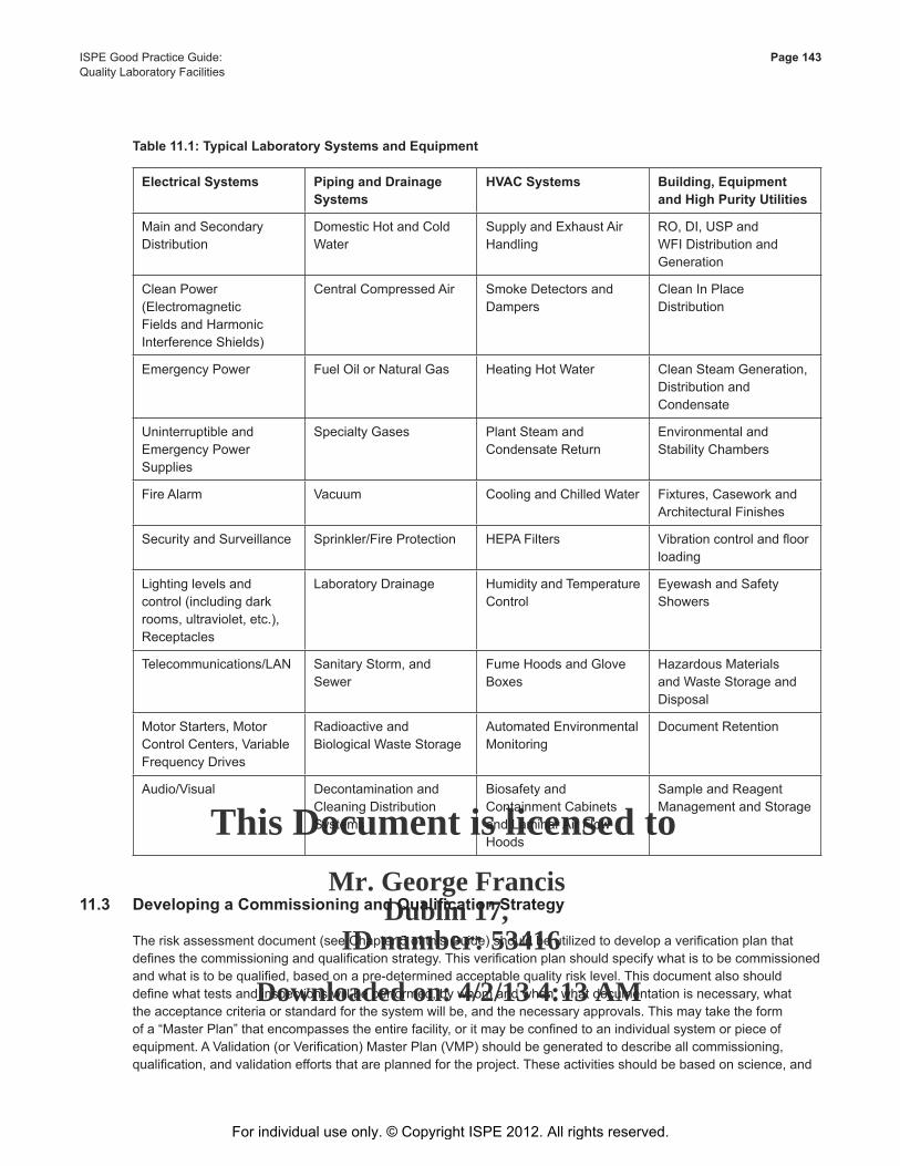
This Document is licensed to
Mr. George FrancisDublin 17,
ID number: 53416
Downloaded on: 4/2/13 4:13 AM
ISPE Good Practice Guide: Page 143Quality Laboratory Facilities
Electrical Systems Piping and Drainage Systems
HVAC Systems Building, Equipment and High Purity Utilities
Main and Secondary Distribution
Domestic Hot and Cold Water
Supply and Exhaust Air Handling
RO, DI, USP and WFI Distribution and Generation
Clean Power (Electromagnetic Fields and Harmonic Interference Shields)
Central Compressed Air Smoke Detectors and Dampers
Clean In Place Distribution
Emergency Power Fuel Oil or Natural Gas Heating Hot Water Clean Steam Generation, Distribution and Condensate
Uninterruptible and Emergency Power Supplies
Specialty Gases Plant Steam and Condensate Return
Environmental and Stability Chambers
Fire Alarm Vacuum Cooling and Chilled Water Fixtures, Casework and Architectural Finishes
Security and Surveillance Sprinkler/Fire Protection HEPA Filters Vibration control and floor loading
Lighting levels and control (including dark rooms, ultraviolet, etc.), Receptacles
Laboratory Drainage Humidity and Temperature Control
Eyewash and Safety Showers
Telecommunications/LAN Sanitary Storm, and Sewer
Fume Hoods and Glove Boxes
Hazardous Materials and Waste Storage and Disposal
Motor Starters, Motor Control Centers, Variable Frequency Drives
Radioactive and Biological Waste Storage
Automated Environmental Monitoring
Document Retention
Audio/Visual Decontamination and Cleaning Distribution Systems
Biosafety and Containment Cabinets and Laminar Air Flow Hoods
Sample and Reagent Management and Storage
Table 11.1: Typical Laboratory Systems and Equipment
11.3 DevelopingaCommissioningandQualificationStrategy
The risk assessment document (see Chapter 5 of this Guide) should be utilized to develop a verification plan that defines the commissioning and qualification strategy. This verification plan should specify what is to be commissioned and what is to be qualified, based on a pre-determined acceptable quality risk level. This document also should define what tests and inspections will be performed, by whom and when, what documentation is necessary, what the acceptance criteria or standard for the system will be, and the necessary approvals. This may take the form of a “Master Plan” that encompasses the entire facility, or it may be confined to an individual system or piece of equipment. A Validation (or Verification) Master Plan (VMP) should be generated to describe all commissioning, qualification, and validation efforts that are planned for the project. These activities should be based on science, and
For individual use only. © Copyright ISPE 2012. All rights reserved.
This Document is licensed to
Mr. George FrancisDublin 17,
ID number: 53416
Downloaded on: 4/2/13 4:13 AM
Page 144 ISPE Good Practice Guide: Quality Laboratory Facilities
product and process knowledge, as well as regulatory requirements, industry standards, and owner’s expectations. This document also should address change management as a result of commissioning or qualification activities. As a “living document,” this plan is subject to revisions that reflect changes in scope or design of the facility.
With regard to the content of a verification plan, ASTM E2500-07 states under section 7.0 [24]:
7.4.2 Verification Strategy:
• The acceptance criteria and verification strategy should be documented in appropriate verification plans.
• The verification plan should define what constitutes acceptable documentation of subsequent verification activities.
• The verification plan should be developed and approved by subject matter experts. Verification plans for systems containing critical aspects should be approved by the quality unit.
It is a recommended GEP to commission all facility equipment and systems to ensure that they are installed in accordance with the specifications, and operate to meet the specifications. This effort becomes the basis of an equipment history file or system reference, aiding maintenance and engineering personnel in repair or replacement assessments, and cost and capability analyses. Documented commissioning of these systems by subject matter experts should assure that the design criteria and specified operating requirements will be met and failure potential minimized.
For example, in a new manufacturing facility project, there will be a validated process, operating on qualified equipment and control systems, with data and information management systems recording critical process parameters, events, and alarms. Utilities may directly affect product quality, while others indirectly support the process. There are also those systems that support operation of the facility, but do not have any effect on the quality of the manufactured process.
A quality laboratory facility can be defined in a similar way. There will be validated methods and operations performed on qualified equipment and control systems, with data and information management systems recording test results used for in-process testing or product release. Utilities may directly affecting the result of the testing, while others support the operation of the facility, but have no affect on test results.
The risk management program should dictate any decision on system or equipment qualification requirements. Qualification should be focused on critical aspects addressed in the process (sample handling, analytical method) related to risk assessment. The determination to qualify should be based on the compliance drivers: product quality impact and patient safety. The risk assessment, having defined risk, would allow the verification plan to define the necessary testing aspects in place to mitigate impact to product quality and patient safety. For example, temperature control within a specified range in a microbiological laboratory or incubation area may provide a better survival condition for damaged or slow-growing cells than typical storage conditions would provide. A qualification of temperature maintenance and system control functions (alarms, trends, etc.) could be needed, in order to provide a high degree of assurance that growth is promoted and a microbial contaminant could be isolated. Conversely, those failures that would result in a loss (reject) of product due to a test failure would be considered quality non-impacting since an Out of Specification (OOS) product would not be released. These types of failure would have a negative affect for a manufacturer both financially and on market supply (patient care), and generally would not be considered acceptable practice.
Just as the requirements of the validated manufacturing process are critical to the assessment of systems in a
manufacturing environment, the requirements of the validated test methods can play a major role in the assessment of systems in a laboratory environment. For example, the USP defines two grades of water:
1. Water for Injection
2. Purified Water
For individual use only. © Copyright ISPE 2012. All rights reserved.
This Document is licensed to
Mr. George FrancisDublin 17,
ID number: 53416
Downloaded on: 4/2/13 4:13 AM
ISPE Good Practice Guide: Page 145Quality Laboratory Facilities
These are considered to be pharmaceutical products. If a validated method specifically calls for either of these two quality grades of water, the system delivering the water should be qualified and maintained in that state. This ensures that the type of water needed for analytical testing used in the test meets the requirements of the validated method. The quality of the water used in testing may be important and how that water is labeled and tested can mean the difference between commissioning only and the need for qualification.
There may be instances where the application of risk assessment determines that qualification is not needed, but is mandated (or interpreted to be) by specific regulation. An example of this is contained in the USP requirement to conduct sterility testing under the same conditions as product manufacturing. It is the responsibility and prerogative of an operating organization to interpret regulation and apply science-based judgment to their qualification decisions.
11.4 Commissioning as Good Engineering Practice (GEP)
The ISPE Baseline® Guide, Commissioning and Qualification [25], defines commissioning as “A well planned, documented, and managed engineering approach to the start-up and turn-over of facilities, systems, and equipment to the End-User that results in a safe and functional environment that meets established design requirements and stakeholder expectations.” The components of a commissioning effort for a new or renovated laboratory will be similar to those outlined for manufacturing facilities. It is important to utilize the risk assessment results to identify those variables that directly affect system operation that could result in adverse business or regulatory exposure, potentially resulting in additional testing in commissioning in support of qualification.
User requirements, functional and design specifications, recognized industry standards from established organizations, or qualified personnel, should be used and referenced to define checks, tests, adjustments, inspections, and performance requirements in the commissioning test document. Established organizations include:
• International Society of Automation (ISA)
• American Society for Testing and Materials (ASTM)
• International Organization for Standardization (ISO)
• International Electrotechnical Commission (IEC)
• National Institute of Standards and Technology (NIST)
• Association for the Advancement of Medical Instrumentation (AAMI)
• American National Standards Institute (ANSI)
• American Society of Heating, Refrigeration and Air Conditioning Engineers (ASHRAE)
• Institute of Electrical and Electronic Engineers (IEEE)
• American Society of Mechanical Engineers (ASME)
Local building codes and all health and safety regulations should be addressed during the design phase of the laboratory, and also should be checked in design review, then verified in commissioning, as needed.
The commissioning test document should identify necessary documentation, such as drawings, manuals and procedures necessary to evaluate, operate, and maintain the system. From a business and quality perspective, a piece of equipment or a laboratory system should be physically maintained and periodically evaluated for optimum operation and efficiency by procedure or policy. Qualification or re-qualification should not be needed to enforce maintenance or performance.
For individual use only. © Copyright ISPE 2012. All rights reserved.
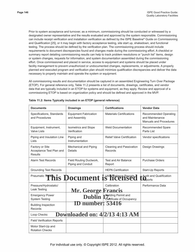
This Document is licensed to
Mr. George FrancisDublin 17,
ID number: 53416
Downloaded on: 4/2/13 4:13 AM
Page 146 ISPE Good Practice Guide: Quality Laboratory Facilities
Prior to system acceptance and turnover, as a minimum, commissioning should be conducted or witnessed by a designated owner representative and the results evaluated and approved by the system responsible. Commissioning can include receipt verification and installation verification as defined by the ISPE Baseline® Guide on Commissioning and Qualification [25], or it may begin with factory acceptance testing, site start up, shakedown, and functional testing. The process should be defined by the verification plan. The commissioning process should include requirements to document discrepancies found and changes made during the commissioning effort. A checklist or summary report detailing commissioning results can help to track problem resolutions or “punch list” items, design or system changes, requests for information, and system documentation assembled during the commissioning effort. Once commissioned and placed in service, access to equipment and systems should be placed under facility management to prevent unauthorized or undocumented changes, replacements, or adjustments. A properly planned and executed program and verification plan should minimize qualification discrepancies and deliver the data necessary to properly maintain and operate the system or equipment.
All commissioning results and documentation should be captured in an assembled Engineering Turn Over Package (ETOP). For general reference only, Table 11.2 presents a list of documents, drawings, certificates, and vendor data that are typically included in an ETOP for systems and equipment, as they apply. Review and approval of a commissioning ETOP is based on organization policy and should be defined and approved in the MVP.
Table 11.2: Items Typically included in an ETOP (general reference)
Documents Drawings Certifications Vendor Data
Specifications, Standards and Procedures
Equipment Fabrication and Assembly
Materials Certifications Recommended Operating and Maintenance Manuals and Procedures
Equipment, Instrument, Valve Lists
Isometrics and Slope Verification
Weld Documentation Recommended Spare Parts List
Piping and Insulation Line Lists
Piping and Instrumentation
Relief Valve Certification Vendor specifications
Factory or Site Acceptance Test Plan and Results
Mechanical and Piping Details
Cleaning and Passivation Records
Design Drawings
Alarm Test Records Field Routing Ductwork, Piping and Conduit
Test and Air Balance Report
Purchase Orders
Grounding Test Records HEPA Certification Start-Up Reports
Pneumatic Testing Utility Balance Reports Audit and Qualification Reports
Pressure/Hydrostatic/Leak Testing
Calibration Performance Data
Emergency Power System Testing
Building Permit and Certificate of Occupancy
Building Inspection Records
Loop Checks
Field Verification Reports
Motor Start-Up and Rotation Checks
For individual use only. © Copyright ISPE 2012. All rights reserved.
This Document is licensed to
Mr. George FrancisDublin 17,
ID number: 53416
Downloaded on: 4/2/13 4:13 AM
ISPE Good Practice Guide: Page 147Quality Laboratory Facilities
11.5 Qualification
For a laboratory, the impact a facility, system, or piece of equipment may have on patient safety is based on a potential release of an OOS product to market, a test failure affecting market supply, or an impact on the ability to conduct a test as validated. The risk management program and verification plan should identify the critical process and product parameters that are routinely verified by the laboratory, and what areas of the laboratory facility, critical systems, and equipment contribute to the verification of these parameters. Those systems that determine or contribute to critical quality attribute verification should be qualified (or verified) under the auspices of the quality unit. Commissioning documentation and supplier test documentation may be leveraged for qualification purposes according to pre requisites determined in the verification plan. After qualification or verification, a review or summary report should confirm that a facility, system, or piece of equipment is “fit for use.” This statement should be approved by the quality unit (at a minimum).
An owner organization should assess a supplier’s quality systems prior to incorporating vendor documentation or
vendor testing of critical parameters in the qualification package. The decision to utilize vendor documentation or supplier testing in the qualification of laboratory systems or equipment needs the concurrence of the quality unit. If issues in supplier practices are identified, it is the owner’s responsibility to identify any necessary remediation, utilizing Subject Matter Experts (SMEs) or qualified personnel.
For individual use only. © Copyright ISPE 2012. All rights reserved.

This Document is licensed to
Mr. George FrancisDublin 17,
ID number: 53416
Downloaded on: 4/2/13 4:13 AM
For individual use only. © Copyright ISPE 2012. All rights reserved.

This Document is licensed to
Mr. George FrancisDublin 17,
ID number: 53416
Downloaded on: 4/2/13 4:13 AM
Appendix 1 European Considerations
For individual use only. © Copyright ISPE 2012. All rights reserved.
This Document is licensed to
Mr. George FrancisDublin 17,
ID number: 53416
Downloaded on: 4/2/13 4:13 AM
Page 150 ISPE Good Practice Guide:Appendix 1 Quality Laboratory Facilities
12 Appendix 1 – European Considerations12.1 Introduction
ThisChapterreviewsthecontentsoftheHVACinformationprovidedintheChapter8ofthisGuideandidentifiesthekey differences between practices and standard as used in the US and practices in the UK EU.
The majority of the guidance and practices are common, but there are some differences which are highlighted in this Chapter.
A list of relevant learned bodies in European countries has been developed with contact details, see Section 12.3 of this Guide. It is recommended that these associations are contacted in the respective country where the laboratory is to reside.
Itshouldbenotedthatmanyglobalorganizationshavetheirownstandardsandthatthesearefrequentlyidentifiedasbeing the ‘organization’ standard; therefore, local considerations should be respected and the contact list has been included.
“Organization” standards, US, or UK standards usually are the benchmark for the criteria used for laboratory design in many areas around the world.
12.2 The Differences
One of the most fundamental differences that exists between the US and Europe are the units of measurement. The US uses the ‘imperial’ form of measurement including temperature in degrees Fahrenheit (°F) and pressure in inches watergauge(″w.g.).InEuropeandtheUK,themetricsystemisadoptedusingSIunits,e.g.,degreescentigrade(°C)for temperature and Pascals (Pa) for pressure. Sometimes millibar (mbar) is also used for pressure.
12.2.1 CleanlinessClassification
EN ISO 14644-1 [44] is currently being adopted throughout the USA and Europe. This standard gives ISO classificationnumbers;ISOClass1toISOClass9andgivesmaximumconcentrationlimitsforarangeofparticles.The ISO classes are determined either at rest or in operation. This is not regulated by EN ISO 14644-1. For further information, see the ISPE Good Practice Guide: HVAC [30].
12.2.2 AirFiltrationStandards
ThefiltrationclassificationsreferredtoinChapter8aretakenfromtheASHRAEStandard52.2-2007[45].TheMinimumEfficiencyReportingValue(MERV)isnotgenerallyusedinEurope.ThestandardsgenerallyusedareBSEN779:2012[46]andBSEN1822-1:2009[47].Thesestandardsclassifyfiltersintofourgeneralstandards,thesebeingGeneral,Fine,HEPA,andULPAwithanoverallrangefromG1throughF9,H10toH14,andH15toU17.Forfurther information, see the ISPE Good Practice Guide: HVAC [30].
12.2.3 Temperature,Humidity,andHumanComfort
TheenvironmentcriteriausedfordesigncanbefoundintheCharteredInstituteofBuildingServicesEngineering(CIBSE)guidessectionA.
The criteria reviews both the requirements of temperature and humidity and overall thermal comfort, the effect of air movement on comfort plus the implications of lighting, sound, and vibration.
CIBSEalsohaveausefulpublicationonventilationandIndoorAirQuality(IAQ).
For individual use only. © Copyright ISPE 2012. All rights reserved.
This Document is licensed to
Mr. George FrancisDublin 17,
ID number: 53416
Downloaded on: 4/2/13 4:13 AM
ISPE Good Practice Guide: Page 151Quality Laboratory Facilities Appendix 1
12.2.4 Ductwork
Ductwork construction standards vary in the UK, and the SMACNA standard referred to in Chapter 8 is not commonly used. The construction standards used are those produced by the Heating and Ventilation Contractors Association (HVCA) and vary depending on the materials being used; they are:
• HVCAspecificationDW/144forsheetmetalductwork
• HVCAspecificationDW/154forplasticductwork
• HVCAspecificationDW/191resinbondedglassfibreductwork
• ThereisarangeofDWstandardsavailablewhichcoveravarietyofsubjectsincludingductworkleakagetesting,internal cleanliness, etc.
Whereroompressureiscritical,highqualityClass1constructionincludingairleakagetestingoftheductworkmaybejustifiable.
12.2.5 Commissioning
The settling to work, balancing of the air systems, and the balancing of any water systems, that may be serving heatingandcoolingbatteries,shouldbeperformedinaccordancewiththeCharteredInstituteofBuildingServices(CIBSE)Commissioningcodes.Thesecodescoverallairandwatersystemsandautomaticcontrols,refrigerationsystems, boilers, and lighting.
AnothersourceofindustrystandardsaretherangeofcommissioningcodesproducedbytheBuildingServicesResearchInformationAssociation(BSRIA).
12.2.6 FumeCupboards(Hoods)
The word fume hood (as opposed to exhaust hood) is a frequently used term. In the UK, this type of enclosure is referredtoasafumecupboard.Thedesign,selection,specification,andinstallationoffumecupboardarecoveredbyBSEN14175-6:2006[48].
Whereabiologicalhazardexists,materialsarenormallyhandledinaMicrobiologicalSafetyCabinet(MBSC),whichareavailableinthreeclassificationsdependingonthetypeofhazardousmaterialbeinghandled.SuchcabinetsarecoveredbyBSEN12469:2000[49].
12.2.7 HVACDesignParameters
A risk assessment should be performed for all laboratory and cleaning operations. This risk assessment will assist in determining if any of the HVAC design parameters are critical to a GMP issue or to a life safety issue. For further informationonriskassessment,seeChapter5ofthisGuide.
Typical temperature criteria for laboratories are the comfort conditions, unless temperature is critical for any tests to beconducted,e.g.,69.8°F(21°C)withanominalrangeof±35.6°F(2°C).HVACcontrolparametersmayberelaxedto conserve energy, but other factors such as condensation and heat stress should be taken into consideration.
As stated in Chapter 8, where additional clothing is worn for higher cleanliness, as in an aseptic laboratory, then the temperature may be lowered to 68°F (20°C).
HumidityrangesbetweenthoseidentifiedinChapter6ofthisGuide,butfrequentlyarangeof40%to60%reductionhumidityistargetedwithspecificcontrolbeingusedwhereneededbythematerialbeinghandled.
For individual use only. © Copyright ISPE 2012. All rights reserved.
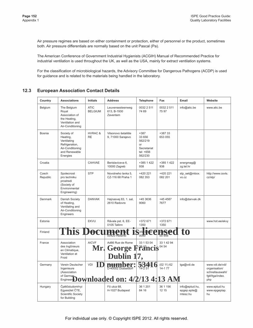
This Document is licensed to
Mr. George FrancisDublin 17,
ID number: 53416
Downloaded on: 4/2/13 4:13 AM
Page 152 ISPE Good Practice Guide:Appendix 1 Quality Laboratory Facilities
Air pressure regimes are based on either containment or protection, either of personnel or the product, sometimes both. Air pressure differentials are normally based on the unit Pascal (Pa).
The American Conference of Government Industrial Hygienists (ACGIH) Manual of Recommended Practice for industrial ventilation is used throughout the UK, as well as the USA, mainly for extract ventilation systems.
Fortheclassificationofmicrobiologicalhazards,theAdvisoryCommitteeforDangerousPathogens(ACDP)isused
for guidance and is related to the materials being handled in the laboratory.
12.3 European Association Contact Details
Country Associations Initials Address Telephone Fax Email Website
Belgium The Belgium Royal Association of the Heating, Ventilation and Air-Conditioning
ATIC BELGIUM
Leuvensesteenweg 613, B-1930 Zaventem
0032 2 511 74 69
0032 2 511 75 97
[email protected] www.atic.be
Bosnia Society of Heating, Ventilating Refrigeration, Air-Conditioning and Renewable Energies
HVRAC & RE
Vilsonovo šetalište 9, 71000 Sarajevo
+387 33 656 562/219or Secretariat tel: +656 562/230
+387 33 653 055
Croatia CAHVAE Berislaviceva 6, 10000 Zagreb
+385 1 422 938
+385 1 422 938
CzechRepublic
Spolecnost pro techniku prostredi (Society of Environmental Engineering)
STP Novotneho lavka 5, CZ-116 68 Praha 1
+420 221 082 353
+420 221 082 201
http://www.csvts.cz/stp/
Denmark DanishSocietyof Heating, Ventilating and Air-Conditioning Engineers
DANVAK Højnasvej 83, 1. sal, 2610 Rødovre
+45 3636 9060
+45 4587 7677
Estonia EKVU Rǎvalapst.6,EE-0105 Tallinn
+372 671 1350
+372 671 1350
www.hot.ee/ekvy
Finland FINVAC Sitratori 5, FIN-00420 Helsinki
358 9 566 0090
358 9 566 00 956
France Association desIngčnieursen Climatique, Ventilation et Froid
AICVF Ad66 Rue de Rome 33 1 53 04 36 10
33 1 42 94 04 54
Germany VereinDeutscherIngenieure (Association of German Engineers)
VDI Postach 10 11 39,D-40002Düsseldorf
(02 11) 62 14-2 51
(02 11) 62 14-1 77
[email protected] www.vdi.de/vdi/organisation/schnellauswahl/fgkf/tga/index.php
Hungary ČpětčstudomŕnyiEgyesületČTE,ScientificSocietyfor Building
Fö utca 68, H-1027 Budapest
36 1 201 84 16
36 1 156 12 15
[email protected], [email protected]
www.eptud.huwww.epgeplap.hu
For individual use only. © Copyright ISPE 2012. All rights reserved.

This Document is licensed to
Mr. George FrancisDublin 17,
ID number: 53416
Downloaded on: 4/2/13 4:13 AM
ISPE Good Practice Guide: Page 153Quality Laboratory Facilities Appendix 1
Country Associations Initials Address Telephone Fax Email Website
Italy Associazione Italiana Condizionamento dell’aria, RiscaldamentoRefrigerazione
AICARR Via Melchiorre Gioia 168, 20125Milano
0267479270
0267479262
[email protected] www.aicarr.it
Latvia AHGWTEL Vagonu iela 20, LV-1009Riga
3717320727
3717615191
Lithuania Lithuanian Thermotechnical Engineers Society
LITES Saulčtekioal.11,2040 Vilnius
37027603 28
3702700497
Netherlands Nederlandse Technische Vereniging voor Installaties in Gebouwen (Dutch Society forBuildingServices)
TVVL De Mulderij 12, Postbus 311, NL-3830 AJ Leusden
+31 33 434 5750
+31 33 432 1581
[email protected] www.tvvl.nl
Norway Norwegian Society of HEVAC Engineers, NORVAC
NORVAC PO.Box2843Töyen,N-0608 Oslo
+47227083 00
+4722693650
Poland Polskie Zrzeszenie InzynierňwiTechnikňwSanitarnych
PZITS UI.Czackiego3/5,00-043Warszawa
+48 22 826 2894
+48 22 826 2894
Portugal Ordem Dos Engenheiros
Av, Antonio Augusto Aguiar3D,1069-030 Lisboa
+351231326 00
+351235246 32
Romania RomanianGeneral Association for Heating, Refrigeration,Air-conditioning, Sanitary and Electrical Engineers
AGFR-AIIR
66 Pache ProtopopescuBlvd,73232Bucharest2
4012506546;401642 42 00;
4012506546;401312 68 80; 40 1 210 3256
Russia Association of Engineers in Heating, Ventilation, Air-conditioning, Heat Supply and BuildingThermalPhysics
ABOK Rohzdestvenkastr.11Russia103754Moscow
+70959218048 (6031, 6946,7023,8076,7286)
www.abok.ru
Slovakia Slovenska spolocnost pre techniku prostredia – SSTP Slovak Society for Environmental Technology
SSTP Kocelova15,81594Bratislava
42175262882(5262955)
42175262991
For individual use only. © Copyright ISPE 2012. All rights reserved.

This Document is licensed to
Mr. George FrancisDublin 17,
ID number: 53416
Downloaded on: 4/2/13 4:13 AM
Page 154 ISPE Good Practice Guide:Appendix 1 Quality Laboratory Facilities
Country Associations Initials Address Telephone Fax Email Website
Slovenia SITHOK Aškerčeva6,1000Ljubljana
+386 1 4771200
+386 1 2518567
www.drustvo-sithok.si
Spain AsociaciňnTčcnicaEspańoladeClimatizaciňnyRefrigeraciňn
ATECYR Instituto Eduardo Torroja,C/SerranoGalvaches/n,28033Madrid
34917671355
34917670638
www.atecyr.org
Sweden Tekniska Föreningen-Riksföreningenför Energi-och Miljöteknik (Swedish HEVAC-Society of Energi and Environmental Technology
VVS Parmmätargatan7,S-112 24 Stockholm
46865408 30
4686549683
Switzerland Schweizerischer Verein von Wärme-und Klima-Ingenieuren
SWKI Solothurnstr. 13, Postfach, 3322 Schönbühl
03185213 00
03185213 01
[email protected] www.swki.ch
Turkey Türk Tesisat Mühendisleri Dernegi
TTMD Tunus Caddesi, GüfteSokak,No:8/7Kavaklidere, Ankara, Turkiye
3124194571
3124195851
[email protected] www.ttmd.org.tr
United Kingdom
Chartered Institution of BuildingServicesEngineers
CIBSE Delta House 222 BalhamHighRoad,LondonSW129BS
441816755211
441816755449
www.cibse.org
BuildingServicesResearchInformation Association
BSRIA OldBracknallLane,WestBracknell,BerkshireRG127AH
44 134 465600
44 1344 65626
www.bsria.co.uk
Yugoslavia Yugoslav Society for Heating, RefrigerationandAir-conditioning,
YUGO KGH
KnezaMilosa7,POBox648,11001Beograd
381 11 323 00 41
381 11 323 1372
For individual use only. © Copyright ISPE 2012. All rights reserved.

This Document is licensed to
Mr. George FrancisDublin 17,
ID number: 53416
Downloaded on: 4/2/13 4:13 AM
Appendix 2 References
For individual use only. © Copyright ISPE 2012. All rights reserved.
This Document is licensed to
Mr. George FrancisDublin 17,
ID number: 53416
Downloaded on: 4/2/13 4:13 AM
Page 156 ISPE Good Practice Guide:Appendix 2 Quality Laboratory Facilities
13 Appendix 2 – References 1. 21 CFR Part 11 – Electronic Records, Electronic Signatures, US Code of Federal Regulations, U.S. Food and
Drug Administration (FDA), www.fda.gov.
2. 21 CFR Part 210 – Current Good Manufacturing Practice in Manufacturing, Processing, Packing, or Holding of Drugs, US Code of Federal Regulations, U.S. Food and Drug Administration (FDA), www.fda.gov.
3. 21 CFR Part 211 – Current Good Manufacturing Practice for Finished Pharmaceuticals, US Code of Federal Regulations, U.S. Food and Drug Administration (FDA), www.fda.gov.
4. Good Manufacturing Practice Guide for Active Pharmaceutical Ingredients – Q7, International Conference on Harmonisation of Technical Requirements for Registration of Pharmaceuticals for Human Use (ICH), www.ich.org.
5. EudraLex Volume 4 – Guidelines for Good Manufacturing Practices for Medicinal Products for Human and Veterinary Use (2008 Edition), ec.europa.eu.
6. NFPA 45: Standard on Fire Protection for Laboratories Using Chemicals, National Fire Protection Association (NFPA) (US), www.nfpa.org.
7. 21 CFR Part 1308 – Schedules of Controlled Substances, US Code of Federal Regulations, U.S. Food and Drug Administration (FDA), www.fda.gov.
8. 21 CFR Part 1301 – Registration of Manufacturers, Distributors, and Dispensers of Controlled Substances, US Code of Federal Regulations, U.S. Food and Drug Administration (FDA), www.fda.gov.
9. Americans with Disabilities Act (ADA), www.ada.gov.
10. NIH Guidelines for Research Involving Recombinant DNA Molecules (The NIH Guidelines), http://oba.od.nih.gov/oba/rac/guidelines/nih_guidelines.htm.
11. Centers for Disease Control and Prevention (CDC), www.cdc.gov.
12. ISPE Baseline® Pharmaceutical Engineering Guide, Volume 6 – Biopharmaceutical Manufacturing Facilities, International Society for Pharmaceutical Engineering (ISPE), First Edition, June 2004, www.ispe.org.
13. National Cancer Institute (US) http://www.cancer.gov/
14. NSF/ANSI49-2011BiosafetyCabinetry:Design,Construction,Performance,andFieldCertificationNSFInternational, 08-Nov-2011, http://www.nsf.org/
15. The Control of Substances Hazardous to Health Regulations (enacted in 1988), UK Legislation, www.legislation.gov.uk.
16. “Performance-Based Occupational Exposure Limits,” American Industrial Hygiene Association (AIHA), www.aiha.org.
17. “Biosafety in Microbiological and Biomedical Laboratories,” US Department of Health and Human Services, Public Health Service, Centers for Disease Control and Prevention, National Institutes of Health, www.cdc.gov/biosafety/publications/bmbl5/
18. National Fire Protection Association (NFPA) (US), www.nfpa.org.
For individual use only. © Copyright ISPE 2012. All rights reserved.
This Document is licensed to
Mr. George FrancisDublin 17,
ID number: 53416
Downloaded on: 4/2/13 4:13 AM
ISPE Good Practice Guide: Page 157Quality Laboratory Facilities Appendix 2
19. U.S. Nuclear Regulatory Commission (NRC), www.nrc.gov.
20. U.S. Department of Agriculture (USDA), www.usda.gov.
21. International Fire Code (IFC), www.iccsafe.org.
22. International Building Code (IBC), www.iccsafe.org.
23. NFPA 1: Fire Code, National Fire Protection Association (NFPA) (US), www.nfpa.org.
24. ASTMStandardE2500,2007,“StandardGuideforSpecification,Design,andVerificationofPharmaceuticalandBiopharmaceutical Manufacturing Systems and Equipment,” ASTM International, West Conshohocken, PA, www.astm.org.
25. ISPE Baseline® Pharmaceutical Engineering Guide, Volume 5 – Commissioning and Qualification, International Society for Pharmaceutical Engineering (ISPE), First Edition, March 2001, www.ispe.org.
26. ISPE GAMP® Good Practice Guide: Validation of Laboratory Computerized Systems, International Society for Pharmaceutical Engineering (ISPE), First Edition, April 2005, www.ispe.org.
27. Quality Risk Management – Q9, International Conference on Harmonisation of Technical Requirements for Registration of Pharmaceuticals for Human Use, www.ich.org.
28. 21 CFR Part 58 – Good Laboratory Practice for Nonclinical Laboratory Studies, US Code of Federal Regulations, U.S. Food and Drug Administration (FDA), www.fda.gov.
29. ISPE Guide: Science and Risk-Based Approach for the Delivery of Facilities, Systems, and Equipment, International Society for Pharmaceutical Engineering (ISPE), First Edition, June 2011, www.ispe.org.
30. ISPE Good Practice Guide: Heating, Ventilation, and Air Conditioning, International Society for Pharmaceutical Engineering (ISPE), First Edition, September 2009, www.ispe.org.
31. ISPE Good Practice Guide: Process Gases, International Society for Pharmaceutical Engineering (ISPE), First Edition, July 2011, www.ispe.org.
32. ISPE Good Practice Guide: Maintenance, International Society for Pharmaceutical Engineering (ISPE), First Edition, May 2009, www.ispe.org.
33. ASHRAE Standard 62.2 – Ventilation and Acceptable Indoor Air Quality in Low-Rise Residential Buildings, American Society of Heating, Refrigeration and Air Conditioning Engineers (ASHRAE), www.ashrae.org.
34. NFPA 70: National Electrical Code (NEC), National Fire Protection Association (NFPA) (US), www.nfpa.org.
35. NFPA 101: Life Safety Code, National Fire Protection Association (NFPA) (US), www.nfpa.org.
36. United States Pharmacopeia – National Formulary (USP-NF), www.usp.org/USPNF. US Pharmacopeia, USP General Chapter Requirements, www.usp.org.
37. European Pharmacopoeia, www.edqm.eu.
38. Japanese Pharmacopoeia, http://jpdb.nihs.go.jp/jp15e/.
39. ISPE Baseline® Pharmaceutical Engineering Guide, Volume 4 – Water and Steam Systems, International Society for Pharmaceutical Engineering (ISPE), Second Edition, December 2011, www.ispe.org.
For individual use only. © Copyright ISPE 2012. All rights reserved.
This Document is licensed to
Mr. George FrancisDublin 17,
ID number: 53416
Downloaded on: 4/2/13 4:13 AM
Page 158 ISPE Good Practice Guide:Appendix 2 Quality Laboratory Facilities
40. ISO 9001:2008 Quality Management Systems – Requirements, www.iso.org.
41. Pharmaceutical Development – Q8, International Conference on Harmonisation of Technical Requirements for Registration of Pharmaceuticals for Human Use), www.ich.org.
42. ISPE GAMP® 5: A Risk-Based Approach to Compliant GxP Computerized Systems, International Society for Pharmaceutical Engineering (ISPE), Fifth Edition, February 2008, www.ispe.org.
43. ISPE GAMP® Good Practice Guide: A Risk-Based Approach to Calibration Management, International Society for Pharmaceutical Engineering (ISPE), Second Edition, November 2010, www.ispe.org.
44. EN ISO 14644-1, International Organization for Standardization (ISO), www.iso.org.
45. ASHRAE Standard 52.2-2007 – Method of Testing General Ventilation Air-Cleaning Devices for Removal EfficiencybyParticleSize,AmericanSocietyofHeating,RefrigerationandAirConditioningEngineers(ASHRAE), www.ashrae.org.
46. BSEN779:2012,ParticulateAirFiltersforGeneralVentilation;DeterminationofthefiltrationPerformance,http://shop.bsigroup.com.
47. BSEN1822-1:2009,HighEfficiencyAirFilters(EPA,HEPAandULPA);Classification,PerformanceTesting,Marking, http://shop.bsigroup.com.
48. BS EN 14175-6:2006, Fume Cupboards; Variable Air Volume Fume Cupboards, http://shop.bsigroup.com.
49. BS EN 12469:2000 Biotechnology – Performance Criteria for Microbiological Safety Cabinets, http://shop.bsigroup.com.
50. ASHRAE Standard 55 – Thermal Environmental Conditions for Human Occupancy, American Society of Heating, Refrigeration and Air Conditioning Engineers (ASHRAE), www.ashrae.org.
51. ISO 7730:2005 Ergonomics of the Thermal Environment, International Standards Organization (ISO), www.iso.
org.
13.1 Further Reading
• ASHRAE–LaboratoryDesignHandbook
• ASHRAEHandbook–Applications–Laboratories
• ASHRAE/ANSI–Z.9.5LaboratoryVentilation
• U.S.GreenBuildingCouncil(LEED)
• Labs21
• BiosafetyinMicrobiologicalandBiomedicalLaboratoriesbyU.S.DepartmentofHealthandHumanServices,Public Health Service, Centers for Disease Control and Prevention, National Institutes of Health, (http://www.cdc.gov/biosafety/publications/bmbl5/)
For individual use only. © Copyright ISPE 2012. All rights reserved.

This Document is licensed to
Mr. George FrancisDublin 17,
ID number: 53416
Downloaded on: 4/2/13 4:13 AM
Appendix 3 Glossary
For individual use only. © Copyright ISPE 2012. All rights reserved.
This Document is licensed to
Mr. George FrancisDublin 17,
ID number: 53416
Downloaded on: 4/2/13 4:13 AM
Page 160 ISPE Good Practice Guide:Appendix 3 Quality Laboratory Facilities
14 Appendix 3 – Glossary14.1 Acronyms and Abbreviations
AAMI Association for the Advancement of Medical Instrumentation
ACDP Advisory Committee for Dangerous Pathogens
ACGIH American Conference of Government Industrial Hygienists
ADA Americans with Disabilities Act
AHJ Authority Having Jurisdiction
AHU Air Handling Unit
ANSI American National Standards Institute
API Active Pharmaceutical Ingredient
ASHRAE American Society of Heating, Refrigeration and Air Conditioning Engineers
ASME American Society of Mechanical Engineers
ASTM American Society for Testing and Materials (International)
BAS Building Automation Systems
BMBL Biosafety in Microbiological and Biomedical Laboratories
BMS Building Management Systems
BOCA BuildingOfficialsCodeAdministrators(International)
BOD Basis of Design
BSC Biosafety Cabinet
BSL Biological Safety Level
BSRIA Building Services Research Information Association
CAPA Corrective and Preventative Action
CAV Constant Air Volume
CDC Centers for Disease Control and Prevention (US)
CDS Chromatography Data System
CE Conformité Européenne
CFD Computational Fluid Dynamic
CFM Cubic Feet of air per Minute
CIBSE Chartered Institute of Building Services Engineering
CLSI Clinical and Laboratory Standards Institute
CSI ConstructionSpecificationInstitute
DCS Distributed Control System
DEA Drug Enforcement Administration (US)
DI Deionized
DNA Deoxyribonucleic Acid
For individual use only. © Copyright ISPE 2012. All rights reserved.
This Document is licensed to
Mr. George FrancisDublin 17,
ID number: 53416
Downloaded on: 4/2/13 4:13 AM
ISPE Good Practice Guide: Page 161Quality Laboratory Facilities Appendix 3
DX Direct Expansion
ECL Exposure Control Limits
EHS Environmental, Health, and Safety
EP European Pharmacopoeia
EMEA European Medicines Agency
ETOP Engineering Turnover Package
EU European Union
FAT Factory Acceptance Testing
FF&E Furniture, Fixtures, and Equipment
FMEA Failure Mode Effects Analysis
FRP Fiberglass Reinforced Plastic
GC Gas Chromatography
GEP Good Engineering Practice
GLP Good Laboratory Practice
GMP Good Manufacturing Practice
GxP Good“x”Practice(seeSection14.2fordefinition)
HACCP Hazard Analysis Critical Control Point
HAZCON Hazards of Construction Risk Assessment
HEPA HighEfficiencyParticulateAir
HPLC High Pressure Liquid Chromatography
HPW HighlyPurifiedWater
HVAC Heating Ventilation and Air Conditioning
HVCA Contractors Association
I/O Input/Output
IAQ Indoor Air Quality
IBC International Building Code
IC Ion Chromatograph
ICH International Conference on Harmonisation
IEC International Electrotechnical Commission – Note for Jim: is this correct?
IEEE Institute of Electrical and Electronic Engineers
IPA Isopropyl Alcohol
ISA International Society of Automation
ISO International Organization for Standardization
IT Information Technology
JP Japanese Pharmacopoeia
KF Karl Fisher
LAL Limulus Amebocyte Lysate
For individual use only. © Copyright ISPE 2012. All rights reserved.
This Document is licensed to
Mr. George FrancisDublin 17,
ID number: 53416
Downloaded on: 4/2/13 4:13 AM
Page 162 ISPE Good Practice Guide:Appendix 3 Quality Laboratory Facilities
LEED Leadership in Energy, Environment, and Design
LIMS Laboratory Information Management Systems
LOD Loss on Drying
MBSC Microbiological Safety Cabinet
MD/V Methods Development/Validation
MEP Mechanical, Electrical, and Plumbing
MHRA Medicines and Healthcare Products Regulatory Agency (UK)
MSDS Material Safety Data Sheet
MVP MasterValidation/VerificationPlan
NC Noise Criteria
NFPA National Fire Protection Association (US)
NIH National Institutes of Health (US)
NIST National Institute of Standards and Technology (US)
NMR Nuclear Magnetic Resonance
NRC Nuclear Regulatory Commission (US)
NSF National Science Foundation
OEB Occupational Exposure Band
OEL Occupational Exposure Limit
OOS OutOfSpecification
OPC Open Connectivity
OSHA Occupational Safety and Health Administration
OTC Over-the-Counter
POU Point Of Use
PPE Personal Protective Equipment
PVC Poly Vinyl Chloride
PW PurifiedWater
QA Quality Assurance
QC Quality Control
RC Room Criteria
RCRA Resource Conservation and Recovery Act
RFI Radio Frequency Interference
RH Relative Humidity
RO Reverse Osmosis
ROI Return on Investment
RPN Risk Priority Number
SAT Site Acceptance Testing
For individual use only. © Copyright ISPE 2012. All rights reserved.
This Document is licensed to
Mr. George FrancisDublin 17,
ID number: 53416
Downloaded on: 4/2/13 4:13 AM
ISPE Good Practice Guide: Page 163Quality Laboratory Facilities Appendix 3
SCADA Supervisory Control and Data Acquisition
SMACNA Sheet Metal and Air Conditioning National Association
SOP Standard Operating Procedure
TLC Thin-layer Chromatography
TLV Threshold Limit Value
TOC Total Organic Carbon
UPS Uninterruptible Power Supply
USDA United States Department of Agriculture
USP United States Pharmacopeia
VAV Variable Air Volume
VFD Variable Frequency Drive
VM Value Management
VMP Validation/VerificationMasterPlan
VOC Volatile Organic Compound
WFI WaterforInjection
WHO WorldHealthOrganization
14.2 Definitions
Acid
A compound of an electronegative element or radical with hydrogen; it form salts by replacing all or part of the hydrogen with an electropositive element or radical. Or, a hydrogen-containing substance that when dissolved in water dissociates to produce one or more hydrogen ions (H+). Acids cause irritation, burns, or more serious damage to tissue, depending on the strength of the acid, which is measured by its pH.
Airlock
An enclosed space with two or more doors and which is interposed between two or more rooms, e.g., of differing classofcleanliness,forthepurposeofcontrollingtheairflowbetweenthoseroomswhentheyneedtobeentered.An airlock is designed for and used by either people or goods.
Active Pharmaceutical Ingredient (API)
Any substance or mixture of substances intended to be used in the manufacture of a drug (medicinal) product and that, when used in the production of a drug, becomes an active ingredient of the drug product. Such substances are intended to furnish pharmacological activity or other direct effect in the diagnosis, cure, mitigation, treatment, or prevention of disease, or to affect the structure and function of the body.
Acute Exposure
A single exposure to a toxic substance that results in severe biological harm or death. Acute exposures are usually characterized as lasting up to 14 days.
Aseptic
Not sterile, but contaminants controlled within established acceptable limits.
For individual use only. © Copyright ISPE 2012. All rights reserved.
This Document is licensed to
Mr. George FrancisDublin 17,
ID number: 53416
Downloaded on: 4/2/13 4:13 AM
Page 164 ISPE Good Practice Guide:Appendix 3 Quality Laboratory Facilities
Autoclave
An apparatus into which moist heat (steam) under pressure is introduced to sterilize or decontaminate materials placedwithin(e.g.,filterassemblies,glassware,etc.).Steampressureismaintainedforpre-specifiedtimesandthenallowed to exhaust. There are two types of autoclaves:
• Gravitydisplacementautoclave:thistypeofautoclaveoperatesat249.8°F(121°C).Steamentersatthetopofthe loaded inner chamber, displacing the air below through a discharge outlet.
• Vacuumautoclave:thistypeofautoclavecanoperatewithareducedsterilizationcycletime.Theairispumpedoutoftheloadedchamberbeforeitisfilledwithsteam.
Barrier System
An open system that can exchange contaminants with the surrounding area, and cannot be decontaminated to the extent possible in an isolator system.
Base
Substance whose chemical reaction characteristic is to establish new bonds by the donation of electron pairs.
Basis of Design (BOD)
A “dynamic” design document that describes the purpose of a given system and/or facility and how they will accomplishtheirrequiredtasks.Thisdocumentiscreatedandapprovedbeforetheissuanceofbidspecificationsandmay be used to develop them. Until the system is developed this is a conceptual document.
Biohazard
An infectious agent(s), or part thereof, presenting a real or potential risk to human, other animals, or plants, directly through infection or indirectly through disruption of the environment.
Biologic
Any therapeutic serum, toxin, anti-toxin, or analogous microbial product applicable to the prevention, treatment, or cureofdiseasesorinjuries.
Calibration
A comparison of a measurement standard or instrument of unknown accuracy to detect, correlate, report, or eliminate byadjustmentanyvariationintheaccuracyoftheunknownstandardorinstrument.
Corrective and Preventive Action (CAPA)
Aqualitysystemdefinedby21CFR820.100;thepolicies,procedures,andsupportsystemsthatenableafirmto assure that exceptions are followed up with appropriate actions to correct the situation, and with continuous improvement tasks to prevent recurrence and eliminate the cause of potential nonconforming product and other quality problems.
Current Good Manufacturing Practice (CGMP)
Current accepted standards of design, operation, practice, and sanitization. The FDA is empowered to inspect drug-manufacturing plants in which drugs are processed, manufactured, packaged, and stored for compliance with these standards.
Chromatography
Method of highly selective molecule separation using columns to purify proteins and other chemical products.
For individual use only. © Copyright ISPE 2012. All rights reserved.
This Document is licensed to
Mr. George FrancisDublin 17,
ID number: 53416
Downloaded on: 4/2/13 4:13 AM
ISPE Good Practice Guide: Page 165Quality Laboratory Facilities Appendix 3
Chronic Exposure
Contact with a substance that occurs over a long time (more than one year).
ClassifiedSpace
An area with airborne viable and non-viable particle contamination controlled within preset limits. A cleanroom designatedbyISOStandard14644-1classificationunits(“InOperation”)orEuropeanCommunity(EC)GradesA,B,C,D(“AtRest”and“InOperation”).Forpharmaceuticalmanufacture,aclassifiedspaceimpliesongoingenvironmental monitoring.
Closed System
Systemsterilized-in-placeorsterilizedwhileclosedpriortouse,ispressureorvacuumtighttosomepredefinedleakrate,canbeutilizedforitsintendedpurposewithoutbreachtotheintegrityofthesystem,canbeadaptedforfluidtransfers in or out while maintaining asepsis, and is connectable to other closed systems while maintaining integrity of all closed systems.
Commissioning
A well planned, documented, and managed engineering approach to the start-up and turnover of facilities, systems, and equipment to the end-user that results in a safe and functional environment that meets established design requirements and stakeholder expectations.
Conceptual Design
Designstage,togeneratevariousalternativesforevaluation.Theprojectteamthenselectstheconceptstobetakenforward into the functional design stage.
Containment
Physical means to prevent the entry of hazardous material into the workplace to protect the worker and the work environment from materials that are highly active biologically or pharmacologically, toxic, or biohazardous, usually in addition to protecting the product from contamination.
• PrimaryContainment:theprotectionofworkersandtheproductfromexposuretopotentiallyhazardousagents,via the use of closed systems and physical segregation.
• SecondaryContainment:thecontrolofcontaminants,throughsystemandequipmentdesign,topreventthereleaseofpotentiallyhazardousagentstotheoutsideenvironment,viaspatiallayoutsandadjacencies,flowpatternsanddirectionalairflowandpressureboundaries.
Contamination
The undesired introduction of impurities of a chemical or microbiological nature, or of foreign matter, into or onto a raw material, intermediate, or API during production, sampling, packaging or repackaging, storage or transport.
Controlled Drugs
Narcotic drugs and psychotropic substances regulated by provisions of national drug laws.
Cross Contamination
The measurable and detrimental contamination of a drug substance or product by another.
Deflagration
Anexothermicreaction,suchastheextremelyrapidoxidationofacombustibledustorflammablevaporinair,inwhichthereactionprogressesthroughtheunburnedmaterialataratelessthanthevelocityofsound.Adeflagrationcan have an explosive effect.
For individual use only. © Copyright ISPE 2012. All rights reserved.
This Document is licensed to
Mr. George FrancisDublin 17,
ID number: 53416
Downloaded on: 4/2/13 4:13 AM
Page 166 ISPE Good Practice Guide:Appendix 3 Quality Laboratory Facilities
Depyrogenation
The removal or destruction of endotoxins.
DesignQualification(DQ)
Documentedverificationthattheproposeddesignofthefacilities,equipment,orsystemsissuitablefortheintendedpurpose.
Detailed Design
Design stage when the documents required for construction bidding and contracting, as well as system and equipment purchase, fabrication, installation and testing are produced.
Direct Impact System
A system that is expected to have a direct impact on product quality. These systems are designed and commissioned inlinewithGoodEngineeringPractice,andinaddition,aresubjecttoQualificationPracticesthatincorporatetheenhancedreview,control,andtestingagainstspecificationsorotherrequirementsnecessaryforcGMPcompliance.
Drug Substance
Any component intended to furnish pharmacological activity or other direct effect in the diagnosis, cure, mitigation, treatment, or prevention of disease, or to affect the structure or any function of humans. The term includes those components that may undergo chemical change in the manufacture of the drug product, and be present in the drug productinamodifiedformintendedtofurnishthespecifiedactivityoreffect.AdrugsubstanceisanAPI.
Excipients (USP)
ComponentsofafinishedmedicinaldrugproductotherthantheActivePharmaceuticalIngredient(API).Theyareincluded in the formulation to facilitate manufacture, enhance stability, control release of API from the product, assist inproductidentification,orenhanceotherproductcharacteristics.
Expiration Date
The date placed on the container/labels of an API designating the time during which the API is expected to remain withinestablishedshelflifespecificationsifstoredunderdefinedconditions,andafterwhichitshouldnotbeused.
Explosion
Areleaseofenergysufficienttocauseapressurewave;arapidorsuddenreleaseofenergythatcausesapressurediscontinuity or blast wave.
Explosive Limits
Therangeofconcentrations(%byvolumeinair)ofaflammablegasorvaporthatcanresultinanexplosionfromignitioninaconfinedspace.UsuallygivenasUpper(UEL)andLowerExplosiveLimits(LEL).
Factory Acceptance Test (FAT)
Thepartialcommissioningandqualificationofequipmentand/orsystemspriortotheirshipmentfromthefabricator’ssite.
Finished Product
Amedicinalproductthathasundergoneallstagesofproduction,includingpackaginginitsfinalcontainer.
For individual use only. © Copyright ISPE 2012. All rights reserved.
This Document is licensed to
Mr. George FrancisDublin 17,
ID number: 53416
Downloaded on: 4/2/13 4:13 AM
ISPE Good Practice Guide: Page 167Quality Laboratory Facilities Appendix 3
Fume Hoods
Units that collect fumes from chemicals, solvents, acids, and other hazardous materials. Hoods may include HEPA filtersifpowdersarepresent,orcarbonfilterstofilterfumesfromtheworksurfaceandreturncleanedairtotheroom.Mostfumehoodsare100%exhaustedtooutdoors.Aglass,PlexiglasTM, or acrylic front panel may be included for worker safety.
FunctionalDesignSpecification(FDS)
Provides the functional design requirements. The FDS says how the direct impact water or steam system will perform itsfunction.Typically,theFDSistestedorverifiedduringcommissioningorqualification.
General Arrangement
Aspecificversionofageneralplantlayoutthatincludesthesysteminterfacepoints,spacerequirements,ergonomics,constructionissues,manufacturingflowofequipment,materials,andpersonnel,maintenancerequirements and future expansion or alterations.
Glove Port
Attachment site for gloves, sleeves, and gauntlets.
Good Engineering Practice (GEP)
Establishedengineeringmethodsandstandardsthatareappliedthroughoutaproject’slifecycletodeliverappropriate, cost-effective solutions.
Good Laboratory Practice (GLP) (MHRA)
GLP embodies a set of principles that provides a framework within which laboratory studies are planned, performed, monitored, recorded, reported and archived. These studies are undertaken to generate data by which the hazards and risks to users, consumers and third parties, including the environment, can be assessed for pharmaceuticals, agrochemicals, veterinary medicines, industrial chemicals, cosmetics, food and feed additives and biocides. GLP helpsassureregulatoryauthoritiesthatthedatasubmittedareatruereflectionoftheresultsobtainedduringthestudy and can therefore be relied upon when making risk/safety assessments.
GxP
One or a combination of GCP, GMP, GLP, GDP – usually used for everything of interest for the Regulatory Bodies. One or more of the following would be represented by “x”: Clinical, Manufacturing, Laboratory, Distribution.
Hazard and Operability Review (HAZOP)
The process of systematically reviewing a facility/system/process to determine potential safety concerns.
Hazardous(Classified)Materials
Gases,vapors,combustibledusts,fibers,orflyingsthatareexplosiveundercertainconditions.
Hazardous Substance
Asubstancewhichbyreasonofbeingexplosive,flammable,toxic,poisonous,corrosive,oxidizing,irritantorotherwiseharmful,islikelytocauseinjury.
HighEfficiencyParticulateAir(HEPA)Filter
Afilterwithanefficiencyinexcessof99.97%for0.3µmparticles.
For individual use only. © Copyright ISPE 2012. All rights reserved.
This Document is licensed to
Mr. George FrancisDublin 17,
ID number: 53416
Downloaded on: 4/2/13 4:13 AM
Page 168 ISPE Good Practice Guide:Appendix 3 Quality Laboratory Facilities
High Pressure Liquid Chromatography (HPLC)
Sometimes called high-performance liquid chromatography, is a separation technique based on a solid stationary phase and a liquid mobile phase. Separations (into distinct bands) are achieved by partition, adsorption, or ion-exchangeprocesses,dependinguponthetypeofstationaryphaseused.EachbandisthenprofiledasthesolventflowsthroughaUVdetector,orbyfluorescence,orrefractiveindexdetectors.
Indirect Impact System
System that is not expected to have a direct impact on product quality, but typically will support a Direct Impact System. These systems are designed and commissioned following Good Engineering Practice only.
InstallationQualification(IQ)
For“DirectImpact”systems,thedocumentedverificationthatallaspectsofafacility,utilityorequipmentthatcanaffectproductqualityadheretoapprovedspecifications(e.g.,construction,materials)andiscorrectlyinstalled.
Isolator
Leaktight enclosure designed to protect operators from hazardous/potent processes or protect processes from people or detrimental external environments or both. A basic enclosure consists of a shell, viewing window, glove/sleeve assemblies,supplyandexhaustfilters,light(s),gauge(s),InputandOutputopenings(equipmentdoorairlocks,Rapid Transfer Ports (RTPs), etc.), and various other penetrations. There are two types of isolators:
• ClosedIsolators:Isolatorsoperatedasclosedsystemsdonotexchangeunfilteredairorcontaminantswithadjacentenvironments.Theirabilitytooperatewithoutpersonnelaccesstothecriticalzonemakesisolatorscapable of levels of separation between the internal and external environment unattainable with other technologies. Because the effectiveness of this separation, closed isolators are ideally suited for application in the preparation of sterile and/or toxic material. Aseptic and Containment isolators are two types of closed isolators.
• OpenIsolators:Openisolatorsdifferfromclosedisolatorsinthattheyaredesignedtoallowforthecontinuousor semi-continuous egress of materials during operation, while maintaining a level of protection over the internal environment. Open isolators are decontaminated while closed, and then opened during manufacturing. Open isolatorstypicallyareusedfortheasepticfillingoffinishedpharmaceuticals.
Note: Containment, barrier isolation and isolation all refer to the same technology, which is enclosing an environment. In the interest of clarifying the existing confusion between the terms “isolators” and “barriers”, and providing authoritative implementation and validation of isolation technology, the Parenteral Drug Association (PDA) publishedinOctober2000theDraftforTechnicalReportNo.34“DesignandValidationofIsolatorSystemsfortheManufacturing and Testing of Health Care Products”.
LaminarAirflow–CleanWorkStation
Aworkstationinwhichtheunidirectionalairflowcharacteristicspredominatethroughouttheentireairspacewithaminimumofeddies(turbulence)tojeopardizecriticalsurfaces.
Microbiology
The study of microscopic life such as bacteria and viruses.
Microorganism
A microbe – A microscopic plant or animal, such as a bacterium, protozoan, yeast, virus, or algae.
For individual use only. © Copyright ISPE 2012. All rights reserved.
This Document is licensed to
Mr. George FrancisDublin 17,
ID number: 53416
Downloaded on: 4/2/13 4:13 AM
ISPE Good Practice Guide: Page 169Quality Laboratory Facilities Appendix 3
Mini-Environment
Theactuallocalizedcontrolspacelimitedbyadefinedenclosurethatseparatesorisolatestheinsidefromtheoutsideenvironment, such that the transfer of potential contamination from one side to the other is minimized or completely eliminated, depending on the design. Minienvironments are not always isolators.
Material Safety Data Sheet (MSDS)
Document describing the chemical and physical properties of a substance as related to its safe handling and storage. The substance manufacturer originates it.
No Impact System
System that will not have any impact, either directly or indirectly, on product quality. These systems are designed and commissioned following Good Engineering Practice only.
Non-UnidirectionalAirflow
Airflowthatdoesnotmeetthedefinitionofunidirectionalairflow;previouslyreferredtoas“turbulent”or“non-laminar”airflow.
Occupational Exposure Limit (OEL)
An OEL is a health-based airborne concentration limit to which worker exposure levels should be controlled. Limits areusuallyexpressedaseight-hourtimeweightedaveragesforexposuresfor40hoursaweekoveraworkinglifetime.
OperationalQualification(OQ)
For“DirectImpact”systems,thedocumentedverificationthatallaspectsofafacility,utility,orequipmentthatcanaffect product quality, perform as intended throughout all anticipated operating ranges.
OutofSpecification
An examination, measurement, or test result that does not comply with pre-established criteria.
Oxidizer
A chemical, which readily oxidizes more reduced substances. Examples of strong oxidizers are ozone, hydrogen peroxide, chloride, persulfates, and oxygen itself.
Packaging
Alloperations,includingfillingandlabeling,whichabulkproducthastoundergoinordertobecomeafinishedproduct.
PerformanceQualification(PQ)
For“DirectImpact”systems,thedocumentedverificationthatallaspectsofafacility,utilityorequipmentthatcanaffect product quality perform as intended meeting predetermined acceptance criteria.
Pharmaceutical Product
Any substance or combination of substances which has a therapeutic, prophylactic or diagnostic purpose, or is intended to modify physiological functions, and is presented in a dosage form suitable for administration to humans.
Potent Compound
• Apharmacologicallyactiveingredientorintermediatewithbiologicalactivityofapproximately15microgramsperkilogram of body weight or below in humans (therapeutic dose at or below 1 milligram).
For individual use only. © Copyright ISPE 2012. All rights reserved.
This Document is licensed to
Mr. George FrancisDublin 17,
ID number: 53416
Downloaded on: 4/2/13 4:13 AM
Page 170 ISPE Good Practice Guide:Appendix 3 Quality Laboratory Facilities
• AnActivePharmaceuticalIngredient(API)orintermediatewithanOELatorbelow10microgramspercubicmeterofairasaneight-hourtimeweightedaverage(TWA).
• Apharmacologicallyactiveingredientorintermediatewithhighselectivity(i.e.,abilitytobindtospecificreceptorsorinhibitspecificenzymes)and/orwiththepotentialtocausecancer,mutations,developmentaleffects,orreproductive toxicity at low doses.
• Anovelcompoundofunknownpotencyandtoxicity.
Preliminary Design (IEEE)
Theprocessofanalyzingdesignalternativesanddefiningthearchitecture,components,interfaces,andtimingandsizing estimates for a system or component.
Product Contact Surface
A surface that contacts raw materials, process materials, and/or product.
Project Execution Plan
Awrittenplanfortheprojectmanagertocommunicatetotheuserandotherstakeholderstheapproachtobetakenforprojectexecution.
Qualification
Action of proving and documenting that equipment or ancillary systems are properly installed, work correctly, and actuallyleadtotheexpectedresults.Qualificationispartofvalidation,buttheindividualqualificationstepsalonedonot constitute process validation.
Quarantine
The status of materials isolated physically or by other effective means pending a decision on their subsequent approvalorrejection.
Radiopharmaceuticals
Drugs (compounds or materials) that may be labeled or tagged with a radioisotope. These materials are largely physiological or subpharmacological in action, and, in many cases, function much like materials found in the body. Theprincipalriskassociatedwiththesematerialsistheconsequentradiationexposuretothebodyortospecificorgansystemswhentheyareinjectedintothebody.
Raw Material
A general term used to denote starting materials, reagents, and solvents intended for use in the production of intermediates or APIs.
Reactivity
The ability of a substance to undergo a chemical reaction (such as combining with another substance). Substances with high reactivity are usually quite hazardous.
Reagent
A substance used (as in detecting or measuring a component, in preparing a product, or in developing photographs) because of its chemical or biological activity.
Relative Humidity (% RH)
The ratio (measured in percent) of actual water vapor pressure in air to the pressure of saturated water vapor in air at the same temperature and pressure.
For individual use only. © Copyright ISPE 2012. All rights reserved.
This Document is licensed to
Mr. George FrancisDublin 17,
ID number: 53416
Downloaded on: 4/2/13 4:13 AM
ISPE Good Practice Guide: Page 171Quality Laboratory Facilities Appendix 3
Release
The discharge of a microbiological agent or eukaryotic cell from a containment system.
Risk(ICHQ9)
Combination of the probability of occurrence of harm and the severity of that harm.
Risk Control
Process through which decisions are reached and protective measures are implemented for reducing risks to, or maintainingriskswithin,specifiedlevels.
Risk Management
Systematic application of management policies, procedures and practices to the tasks of analyzing, evaluating, and controlling risk.
Sanitization
To make sanitary by cleaning or disinfecting. That part of decontamination that reduces viable microorganisms to a definedacceptancelevelnormallyachievedbyusingachemicalagent,steamordryheat.
Segregation–Primary
Theuseofphysicalfacilitydesignelementstodefinethebasicorganizationofthebiopharmaceuticalplantdesignandestablishenvironmentallycontrolledworkareasaroundspecificstepsoftheprocess,e.g.,theestablishmentofclassifiedareas.Itprovidesdistinctenvironmentalprotectionfortheprocess/productfromcontamination,andistraditionally accomplished by the designation of dedicated areas, staff, and supporting mechanical systems. FDA CBERsuggestsdiscussionofsegregationconceptsmorespecifically,addressingphysicalsegregationorproceduralsegregation.
Segregation–Secondary
The use of procedural or chronological controls to minimize potential interactions or contamination. It is usually applied in instances where supporting components, equipment, or product are closed and adequately protected from the surrounding environment. Such secondary separation mechanisms can vary widely and include storage of raw materials in different stages of quarantine; clean/dirty equipment areas; and general access paths/process areas. Whereasprimarysegregationcontrolstheimmediatequalityoftheprocess,secondarysegregationmeasuresaretraditionally implemented to minimize the potential for human error. FDA CBER suggests discussion of segregation conceptsmorespecifically,addressingphysicalsegregationorproceduralsegregation.
Site Acceptance Test (SAT)
Inspectionand/ordynamictestingofthesystemsormajorsystemcomponentstosupportthequalificationofanequipment system conducted and documented at the manufacturing site.
Solvent
An inorganic or organic liquid used as a vehicle for the preparation of solutions or suspensions in the manufacture of an intermediate or API.
Stability
Thecapabilityofaparticularformulation,inaspecificcontainer/closuresystem,toremainwithinitsphysical,chemical,microbiological,therapeutic,andtoxicologicalspecificationsforaspecifiedanticipatedshelflife.
For individual use only. © Copyright ISPE 2012. All rights reserved.
This Document is licensed to
Mr. George FrancisDublin 17,
ID number: 53416
Downloaded on: 4/2/13 4:13 AM
Page 172 ISPE Good Practice Guide:Appendix 3 Quality Laboratory Facilities
Standard Operating Procedure (SOP)
Writtenandapprovedprocedurestoensurethatactivitiesareperformedthesamewayeachtime.AcomprehensiveSOP program must be in place in any regulated organization.
Sterile
Absence of life; usually refers to absence of viable microorganisms.
Sterile Transfer
In biopharmaceuticals, the transfer of material from a vessel to another vessel without contamination from the surrounding environment or from the transfer device.
Sterilization
Referstothekillingofmicroorganismsinthedistributionsystem.Thisisnormallydoneperiodicallybyflushingasterilizing solution, such as hydrogen peroxide or ozone, through the distribution piping system. In some systems, ozoneiscontinuouslyinjectedatlowlevelsforcontinuoussterilization.
Test
Anactivityinwhichasystemorcomponentisexecutedunderspecifiedconditions,theresultsareobservedorrecorded, and an evaluation is made of some aspect of the system or component.
Toxic
Pertaining to a substance that is harmful. The toxicity of a substance is the potential of that substance to cause harmful effects. These effects can strike a single cell, a group of cells, an organ system, or the entire body. A toxic effect may be visible damage, or a decrease in performance or function measurable only by a test. All chemicals can cause harm, but when only a small amount can be harmful, the chemical is considered toxic. Toxic materials may be solid,liquid,gas,vapor,dust,fume,fiber,andmist.
Unidirectional Air Flow
Controlledairflowthroughtheentirecross-sectionofacleanzonewithasteadyvelocityandapproximatelyparallelairstreams. Note:Thistypeofairflowresultsinadirectedtransportofparticlesfromthecleanzone.
UniformityofAirflow
Unidirectionalairflowpatterninwhichthepoint-to-pointreadingsofvelocitiesarewithinthedefinedpercentageoftheaverageairflowvelocity.
UserRequirementSpecification(URS)
A description of the requirements of the facility in terms of product to be manufactured required throughput and conditions in which the product should be made.
Utility Systems
Facility-widesystemsnottailoredtoaspecificprocessandthatdonothavecontactwiththedrugsubstanceorpotential drug substance.
Validation
Establishingdocumentedevidencewhichprovidesahighdegreeofassurancethataspecificprocesswillconsistentlyproduceaproductmeetingitspredeterminedspecificationsandqualityattributes.
For individual use only. © Copyright ISPE 2012. All rights reserved.

This Document is licensed to
Mr. George FrancisDublin 17,
ID number: 53416
Downloaded on: 4/2/13 4:13 AM
This Document is licensed to
Mr. George FrancisDublin 17,
ID number: 53416
Downloaded on: 4/2/13 4:13 AM
Confi dence means having a single, virtually audit-proof protocol for all your multi-vendor qualifi cation requirements. And confi dence is the reason why since 1995, labs in North America and Europe have continued to rank Agilent as the #1 choice for general compliance services. Want to improve your validation consistency, free up staff time, and reduce costs? We’re ready to help. Visit: www.agilent.com/chem/comply
17 YEARS TRUSTOF COMPLIANCELEADERSHIP
www.agilent.com/chem/comply
As voted by customers fi ve consecutive times since 1995
© Agilent Technologies, Inc. 2012