How to cutting toyota key by automatic v8 x6 key cutting machine

ISP – 07NT
Automatic controller of cutting thickness for conveyor cutting machines
Assembly and operation manual
The automatic ISP-07NT controller of cutting thickness is designed for attaching to vertical conveyor cutting machine. Before assembly and start-up of the controller, please read the below manual carefully, the instructions within will facilitate proper start-up and ensure fail-safe exploitation of our product.

2 www.selbit.pl
Contents : Chapter 1 - Assembly and connection Chapter 2 - First start-up Chapter 3 – Checking controller parameters Chapter 4 - Cutting in regular mode (board after board) Chapter 5 - Cutting in regular mode without removing boards after each cutting Chapter 6 - Cutting with manual measurement ( program ) Chapter 7 - Possible issues and troubleshooting
CHAPTER 1 Assembly and connection While assembling the controller inside the machine, below instructions need to be followed exactly. Point - 1 Before assembling in the control panel (fig. 1), it is necessary to cut a rectangular opening in it, with dimensions 175 x 140 mm. The opening should be done carefully, to ensure a tight fit along the whole perimeter of the rubber seal of the front panel. Possible serrations resultant from cutting need to be smoothed out with a fine file and secure from corrosion, by painting with good-quality paint or lacquer. If the control panel space is insufficient for mounting the controller, it may be attached in any place as an additional, independent device (fig. 2). Fig.1 - mounting the controller in the machine control panel

3 www.selbit.pl
Fig. 2 - attachment of controller as an independent device In case of attachment of the controller as an independent device it might be, after finishing assembly, fixed to the machine frame directly by four 4,1x 10 bolts that come with the set or, should a necessity arise, make an additional fixing element which will serve as a distancing support after fixing it to the back of the body (fig. 2, element E). Electrical assembly:
WARNING ! Due to the possibility of electric shock, all connections need to
be made only with the machine power disconnected completely. To be certain of this, switch off the main machine switch !!! All machine connections should be done with double – insulated wires, designed for control devices powered with 230 V alternating current. The cables that enter the body should be round, with diameter fitted to the glands mounted in the back of the body. The cable ends should be cleaned and fitted with tunnel fittings similar to the ones used in the revolving encoder, or tinned before fixing. This is important for proper and fail-safe future operation of the controller. In order to ensure safe, proper operation, connections need to be performed exactly as stated in the below steps, as faulty connection may cause disturbances in operation of the controller. The machine in which we install the controller must have working head limit switches, and the up – down advance contactors should be secured from engaging both at the same time!
4 www.selbit.pl
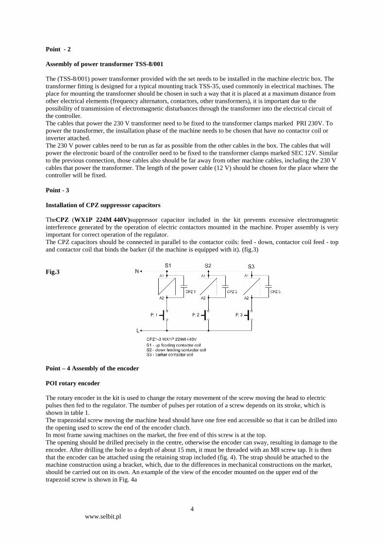
Point - 2 Assembly of power transformer TSS-8/001 The (TSS-8/001) power transformer provided with the set needs to be installed in the machine electric box. The transformer fitting is designed for a typical mounting track TSS-35, used commonly in electrical machines. The place for mounting the transformer should be chosen in such a way that it is placed at a maximum distance from other electrical elements (frequency alternators, contactors, other transformers), it is important due to the possibility of transmission of electromagnetic disturbances through the transformer into the electrical circuit of the controller. The cables that power the 230 V transformer need to be fixed to the transformer clamps marked PRI 230V. To power the transformer, the installation phase of the machine needs to be chosen that have no contactor coil or inverter attached. The 230 V power cables need to be run as far as possible from the other cables in the box. The cables that will power the electronic board of the controller need to be fixed to the transformer clamps marked SEC 12V. Similar to the previous connection, those cables also should be far away from other machine cables, including the 230 V cables that power the transformer. The length of the power cable (12 V) should be chosen for the place where the controller will be fixed. Point - 3 Installation of CPZ suppressor capacitors TheCPZ (WX1P 224M 440V)suppressor capacitor included in the kit prevents excessive electromagnetic interference generated by the operation of electric contactors mounted in the machine. Proper assembly is very important for correct operation of the regulator. The CPZ capacitors should be connected in parallel to the contactor coils: feed - down, contactor coil feed - top and contactor coil that binds the barker (if the machine is equipped with it). (fig.3) Fig.3 Point – 4 Assembly of the encoder POI rotary encoder The rotary encoder in the kit is used to change the rotary movement of the screw moving the head to electric pulses then fed to the regulator. The number of pulses per rotation of a screw depends on its stroke, which is shown in table 1. The trapezoidal screw moving the machine head should have one free end accessible so that it can be drilled into the opening used to screw the end of the encoder clutch. In most frame sawing machines on the market, the free end of this screw is at the top. The opening should be drilled precisely in the centre, otherwise the encoder can sway, resulting in damage to the encoder. After drilling the hole to a depth of about 15 mm, it must be threaded with an M8 screw tap. It is then that the encoder can be attached using the retaining strap included (fig. 4). The strap should be attached to the machine construction using a bracket, which, due to the differences in mechanical constructions on the market, should be carried out on its own. An example of the view of the encoder mounted on the upper end of the trapezoid screw is shown in Fig. 4a

5 www.selbit.pl
Fig. 4 Photo. 4a
Table 1
Screw pitch ( mm. \ rev. ) Type of encoder Divisor 3 Rotary 42 imp./rev. 28 4 Rotary 42 imp./rev. 21 5 Rotary 50 imp./rev. 20 6 Rotary 48 imp./rev. 16 7 Rotary 42 imp./rev. 12 8 Rotary 48 imp./rev. 12 9 Rotary 50 imp./rev. 5 10 Rotary 50 imp./rev. 10
Machine chain conveyor MSK 320 + MB 320 linear 5
The data in the table should be used during the regulator parameter check procedure
It is necessary to keep the rotary encoder cabling away from other electrical wires. By fixing it with clamps, it is fixed to the place where the dial is mounted.Please note it is necessary to check the tightness of the encoder cable connector to ensure correct tightness of the connection!!! MSK320 linear encoder (encoder version for chain sawing machines) In the case of a machine with a chain operated head, use a linear encoder type MSK-320 that works with the magnetic tape MB-3200. In the case of a machine with a chain operated head, use a linear encoder type MSK-320 that works with the MB-3200 magnetic tape. For a machine with a chain operated head, use a linear encoder type MSK-320 that works with the MB-3200 magnetic tape). It is necessary to only stick a part of the tape to protect the adhesive coating when gluing, then stick the first section starting from the top. Then gradually depress the film from the further part while gluing the tape to the surface. When applying pressure a rubber roller for better pressure can be used. It is necessary to carefully stick the tape so that it does not bulge and that the tape is glued evenly in the straight line.After sticking the first part, a protective steel strip is stuck on while maintaining the recommendation such as in the first bonding. Both the tape and strip should be evenly glued on each other. The MSK 320 sensor with the cable should be mounted on the stationary part of the machine (with respect to the controller) so as not to cause cable movements that could damage it. When mounting the sensor as a movable one, it is necessary to secure it in movable rails to prevent its uncontrolled creasing. The sensor should be screwed with two screws passing through the housing so that it is guided over the tape at a distance of 1 to 1.5 mm parallel to it. When carrying the cable from the sensor, it is necessary to ensure that it is at the maximum distance from other conductors and electrical devices. The tape which moves over the sensor cannot be approached before assembly, during and after the magnetic field sources (permanent magnets, electromagnets) under the threat of damage.

6 www.selbit.pl
Every now and then the surface of the tape should be cleaned with dust and dirt with a soft brush. It is not necessary to hit the tape or sensor. The sensor must be mounted with a SCALE SIDE sticker in the direction of the magnetic tape. The sensor and tape should be mounted in such a way that throughout the entire operating motion of the MSK-320 sensor head which stays within its reach within the range of the underlying magnetic tape. Particular attention should be paid to the stability of the mounting of the sensor and the tape so as to avoid vibration of the components. Sensor and magnetic tape mounting example
Point - 5 Connection of contactor control wires Buttons to control the feed head downward and upward, in which the machine is factory equipped should be the short circuiting type without support (should short circuit its contacts when pressed and open out when the button is released). For the top-down stroke control buttons on the machine's console it is necessary to attach a cable containing two pairs of cables in double circular insulation, of such a diameter that it can be passed through a larger choke in the back of the regulator housing. One pair of wires in parallel (fig. 5) to the feed terminals of the down button are connected, the other pair is analogously linked to the upstream push-button terminals. It is necessary to

7 www.selbit.pl
remember to install the clamping bushes or following terminal tin plating. Both pairs of wires should differ in colour, which will facilitate later, proper connection to the appropriate terminals on the regulator plate. The wiring is kept away from other electrical wires and is to be put in the place of the regulator console.
Fig. 5
The cables to which the contactors will be controlled directly to the contactors can also be connected, so as to retain the original control circuit but the solution discussed above is simpler. Point - 6 Attaching the prepared cables to the regulator plate and assembling the housing. After all the necessary connections have been made, the cables to the regulator plate can be connected. In the rear of the housing three PG type chokes can be screwed in, fixing them with nuts from the inside of the housing.The cables are successively introduced through the chokes: - through the largest contactor control cable choke (two pairs of wires from the control buttons) - through the central cable choke from the rotary encoder - through the choke closest to the centre of the housing 12V power cable (cable from SEC 12V of the TSS8 /
001 transformer). The 12V power supply cables are tightened to the connector marked PWR on the regulator plate after having prepared the terminals. The control cables contactors are connected successively: - Pair number 1 of the contactor controlling the feed contactor - down to the connector marked as OUT.1 of
the regulator - Pair number 2 of the contactor controlling the feed contactor - up to the connector marked as OUT.2 of the
regulator
Power 12V TSS 8/001

8 www.selbit.pl
Rotary encoder cable is in turn connected to the connectors marked with ENCODER: - brown POI cable to the plus (+) connector - blue POI cable to the minus (-) connector - white POI cable to the W-1 connector - blackPOI cable to the W-2 connector Connection of the MSK-320 magnetic encoder in the frame sawing machine with the head moved on the chain: It is necessary to connect the magnetic encoder cable to the connectors marked ENCODER: - brown MSK-320 cable to the plus (+)c onnector - black MSK-320 cable to the minus (-) connector - red MSK-320 cable to the W-1connector - orange MSK-320 cable to the W-2connector Note!!Incorrect wiring will damage the encoder!!
Chapter 2 First start up
Checking correct connection of the regulator
In order to verify the connection, it is necessary to follow these steps: - When the power is turned on, it is necessary to check whether ISP 07 is displayed. If not, it is necessary to
check the wiring of the TSS 8/001 transformer and to try again. - When the ISP 07 disappears, it is necessary to press the manual control button on the bottom of the machine
console. Please note that the dimension displayed in the "Real Size" window decreases as the head moves downward while manually lowering the head. Similarly, by pressing the manual control button up, the dimension in the "Real Size" window should increase as the head moves up. If the meter is operating improperly, i.e. the display value decreases while the head moves upwards and it is moving downward, it is necessary to replace the black and white cables (or red-orange) (ENCODER, W-1, W-2) and recheck the correct counting. Checking the correctness of counting is very important, if the direction of counting is not correct, the regulator will not function.
- After checking the correct counting, it is necessary to briefly press the number 8 key on the panel, the number 8 should appear in the "Position Size" window. Now it is necessary to press the "START / next position" button briefly, the regulator should cause the head of the machine to move briefly downwards. If the head is moving in the wrong direction, check the correct connection of the control cables for the upstream and downward feed contactors to the appropriate terminals, if necessary, replace the OUT.1, OUT.2 connectors. The correct connection, as in the case of an encoder, is necessary for proper operation of the regulator.
After completing all connections and checking the correct operation, the regulator housing can be placed on.
9 www.selbit.pl
Before inserting the front panel into the back of the housing or console, it is necessary to check that the rubber gasket is in its groove on the perimeter of the panel. This is important in order to ensure proper tightness of the connection and to prevent contamination from entering the housing. After inserting the panel into the back of the housing, it is necessary to screw it with the 4.1x12 four screws in the set. It is recommended to check the correct operation as described in the section "first regulator starter" before final fitting and tightening to the machine". After making sure that the regulator is properly connected and operating according to the description, the protection caps can be pressed into the screw guide holes, and tighten the regulator to the machine. The mounting of the regulator on the console proceeds in the same way as above, the only difference being that the front panel is screwed to the back of the casing through the casing of the console. After placing on it is necessary to gently pull the cables out of the PG chokes, in order to remove unnecessary excess from the inside of the housing (do not pull the cables too hard so as not to damage their connections to the terminal block), then it is necessary to tighten the outer PG bolt nuts, sealing the insertion points of the cables. Now, when assembled as an independent device, the entirety can be tightened to the machine or bracket, using four screws of 4.1x10, by screwing them into four openings for that purpose, in the rear of the regulator housing.
Chapter 3
Checking the parameters of the regulator 1 - Checking the value of the input divider In order to do this, it is necessary to switch off the power supply, then turn it on and while the dial indicator is displaying ISP 07 press and hold the " Auto Mode " button for about 3s. The regulator will display the "Position Size" divider symbol on the left and its current value on the right of the window. It is necessary to check that the value of the divisor is in line with the table previously read. If the value is not correct, it is necessary to enter the correct one and save it to the controller by briefly pressing the "Start" key, "Save" confirms saving the divider. When approving the divisor, the controller displays "Er Cal", indicating the need to enter a dimension from the track level!
It is necessary to remember that after checking or adjusting the value of the divisor, the steps listed in points 2 and 4 of chapter 3 must be followed - "checking the regulator parameter setting ", without which the regulator will not fun ction.
2 – Entering the actual height at which the saw is located It is necessary to check that the machine's mechanical gauge (millimeter scale with saw blade height) is properly scaled, The height of the head from the machine track that the indicator shows should correspond to the actual saw height from the machine track. A properly scaled gauge measure will make it easier to check the parameters of the regulator later. Correct calibration is important for proper adjustment of the regulator. If the gauge is properly scaled,it is necessary to set the saw so that the indicator stops at full millimeters, e.g. 125, Read exactly what height shows and enter its value into the positioner memory as follows: Press and hold the "Real Set "button for approx. 3s, horizontal bars will appear on the top display. Now enter the dimension from the track level read from the machine gauge using the numerical keys of the regulator. Pressing subsequent buttons with the digits of the entered dimension should be done without undue delay, too long a break is treated by the regulator as the end of providing a number. If a mistake occurs while entering, it is necessary to wait approx. 3 seconds and then proceed to enter dimension. The dimension is entered in the normal order, for example 125, pressing the 1-2-5 keys. After entering the dimension, save the parameter, as before, by briefly pressing the "Start" button. TheSavinscription confirms memory saving. 3 – Registering therzasupiły value installed in the machine

10 www.selbit.pl
Press and hold the saw symbol button for approx. 3 seconds. The row symbol will appear on the display as well as its current entered size. Its value can now be checked or subsequently changed depending on the frame saw machine being used. By entering the new row value it is necessary to remember that it is provided with the accuracy of one decimal place. By wanting to enter the row size of the saw it is necessary to remember that it is equal to 2mm for example, and press button 2 and then button 0 immediately. The registered diameter should be visible on the display in the form of 2.0. After checking or entering the new rowvalue, it is saved to the memory briefly pressing „Start...and confirmed by the inscription „Sav” visible for a moment on the display. 4 –Autocalibration (adjusting the regulator operation to a given machine) Set the saw head manually (using the buttons and directing manually on the console of the machine) at a height of approx. 100mm on the level of the rail and then proceed as follows: Press and hold the „Auto Mode” button for approx. 3s. The inscription „Aut” will appear on the upper display, and then check if the head can be safely started in the auto-calibration mode. If starting-up the head does not threaten safety of persons in the surrounding vicinity, press the „Start” button. The regulator will automatically perform two movements downwards, and then nine movements upwards. After completing the calibration movements, the regulator will shut down the head driver, and the inscription „End” will appear on the display confirming the correct completion of auto-calibration.
Prior to commencing daily work, it is recommended to check whether the height displayed in the „Real Size” window is in accordance with the height of the saw above the rail, which the machine millimeter measure shows. For the sake of ensuring maximum operation precision of
the regulator, it is necessary to carry out the Autocalibration procedure at least 1-2 times per week (description in point 4). The inertness of the mechanical elements of the machine changes depending on external conditions, temperature, friction of the trapezoid screws after lubricating as well as other similar factors. In order that the regulator adjusts its work to current conditions and also obtains the best possible accuracy, the operator should remember to carry out auto calibration activities, given the fact that it does not take up too much time, and its execution becomes routine and simple for everyone after a few days. After correctly carrying out the procedures described in points 1-4, the regulator is ready to commence operation. If for any reason it is not possible to carry out any one of the above points 1...4, or following execution the regulator does not function correctly, it is necessary to check chapter 7 „Possible problems and methods of removing them” and the cause of discrepancy; and following removal it is necessary to carry out points 1...4 again.
Using the controller in practice
The controller provides for the cut of the saw, the thickness visible on the display correlates with the real thickness of the board to be cut. In the following chapters we describe the methods of cutting, with use of options available with the controller.
Chapter 4
Cutting in regular mode (board after board) Cutting in regular mode is the simplest cutting method. In this mode we measure the log from the top, into individual boards. To do this, we have to set the saw, with manual control buttons, to the line of the first cut from the top. We saw the log, take the cut board from the log, and then press the “return” button, which causes the saw to lift above the material, so that the head can be safely returned to the start of the cut. Now we can change the thickness of the next cut, visible on the bottom display (Position Size), to a different one, entered from the numeric keypad, or leave the previous thickness. After choosing the thickness of the cut, press the “Start” button shortly, the controller will set the saw at the height consistent with the previously set thickness of the next board. Now we can perform the next cut and analogously, after finishing it, we take the next board off the log and press “Return”, to return to the log start. If we want the saw to return to the line of the last cut after using the “Return” button, press this button again.

11 www.selbit.pl
Chapter 5
Cutting in regular mode without removing boards after each cut We start the cutting in this mode by setting the saw at a height slightly above the log, along its whole length. This will be the height to which the saw will return automatically, each time the “Return” button is pressed, this way the boards won’t have to be removed off the log after each cut. After setting the saw, press and hold for about 3 seconds the button with the spiral and arrows symbol on it. The left display will show horizontal bars, signaling the confirmation of the height to which the saw will return. Next we set the saw with the manual control buttons, to the height where we want to make the first cut. After performing the setting, make the cut in a manner analogous to the “board after board” method. After each consecutive cut, when we push the “Return” button, the saw will be raised to height predetermined at the beginning of the cut. To turn off the predetermined height, press shortly on the spiral and arrows button.
Chapter 6 Cutting with manual measuring (on - off program) Using the function of manual measuring from the bottom, we can plan consecutive measures of the log. It is useful when, for example, we want to leave square timber with a determined thickness on the track, and cut boards of different dimensions above it, that will be measured over the square timber, towards the top of the log. To use the function, set the saw using the manual control buttons to the size of the square timber that is to be left on the track after the cut is finished (e.g. At 60 mm height, when a 60 mm square timber is desired). Now, shortly press the “Program” button. The left display (Position number) will show two zeros, signaling entering into the measuring function, now we can enter the first desired dimension, using the numeric keypad. After the dimension is entered, press “Start”, the controller will raise the head with the saw to the determined dimension and signal the readiness of the first position, by displaying “01” on the left display. Enter the consecutive positions and confirm them by pressing the “Start” button. After you enter all the desired positions, when cutting is done after removing each consecutive board off the machine track, we can finish the planning by shortly pressing the spiral and arrows button, the left display will show a bracket signaling cutting with removal of each consecutive board, after it’s been cut. Now we make the cut, then we remove the cut material, press the “Return” button and after the saw returns to the start of the track, again press the “Start” button, to set the next cut position. The left display shows the consecutive cut positions up to the 01 position, which is additionally accompanied by an “End Pro” command. The cutting process is finished, you may now leave the measuring function by shortly pressing the “Start” button. You may quit the planning function anytime, by pressing the “Program” button twice. When cutting with planning it is possible, like in chapter 5, to cut the whole material without taking the individual boards off after cutting, until the whole operation is over. To use this option, you need to plan out all the necessary dimensions as described before, and then manually raise the saw to a height allowing for the saw to freely pass the block along its whole length (as described in chapter 5). After raising the saw, press and hold for three seconds the spiral and arrows button, the left display will show three rows of bars. The upper display “Real Size” will turn dark. Now press the “Start” button, the saw will be set to the first cut position, which will be signaled by the “Cut” command on the bottom display. Next we make the cut and, without taking the cut material off, press the “Return” button, return the saw to the track start and press the “Start” button. The saw will be set to the next cut position. Repeat this to cut all the planned positions up until position “01”, which is the last position. The end of the cut will be signaled by the “End” command, like before. After the cutting cycle is over, you may take all the cut material off the log.
12 www.selbit.pl
Chapter 7 Possible issues and troubleshooting To use this advice, verify the pitch of the machine screw that lowers the head. The pitch should be measured and noted below: ------------------------------------------------------------------------------------------------------------------------------------- The pitch of the trapeze screw in this machine is - .................. mm ------------------------------------------------------------------------------------------------------------------------------------- Now check the type of encoder mounted in the machine at the end of the screw (photo 4a). The encoder type is marked on the side sticker, and signifies how many impulses per one revolution the given encoder produces. After reading this number, (e.g. 43 imp / rev), note it below: ------------------------------------------------------------------------------------------------------------------------------------- Th encoder type in this machine is - Rotational- .................... imp/rev ------------------------------------------------------------------------------------------------------------------------------------- Now, using table no.1 from point 4 of the manual, check what divisor should be saved to memory for the controller to work at the given screw pitch. E.g., for screw pitch 7 mm and a converter marked 42 imp / rev, the divisor from the table is 12. After establishing the proper divisor using the table, note it below: -------------------------------------------------------------------------------------------------------------------------------------- The input divisor for this machine is - .......................... -------------------------------------------------------------------------------------------------------------------------------------- Noting of these parameters will facilitate their later verification without the necessity to measure the screw again, etc. Locating the causes of faulty controller operation. Pinpointing the cause of improper operation of the regulator In case of improper operation of the regulator, it is necessary to determineyhe cause of failure using the following description: 1 - The regulator incorrectly sets positions or does not stop the movement of the head at all. In this situation, it is necessary, above all, to check the input divider (chapter 3 point 1 and then point 2) 2 - The regulator incorrectly sets the dimensions of the cut board: In this situation it is necessary to check - The row value entered to the memory of the regulator in accordance with the description in point 3, chapter 3 „Checking the parameters of the regulator”, if the value is correct, it is necessary to check if the row value of the saw set in the machine corresponds with that entered in the regulator.
- Carry out the activities described in points 2 and 4 of chapter 3 – „checking the parameters of the regulator”
(checking conformity of the actual height of the saw with the height displayed and the autocalibration) - if the symptom continues to occur, it is necessary to check if the value of the input divider is correct (chapter 3 point 1 and point 2) -if the symptom is still present, it is necessary to check the quality of the clutch connecting the encoder with the machine screw. The clutch should not have cracks, should be tightened so as not to slide with the encoder roller and its rotation should be smooth without jamming. 3 – After pressing the „Start” or „Return” button, the head does not move from its position and the regulator displays the „Err” inscription. In this situation it is necessary to check:

13 www.selbit.pl
- the condition of the output connections controlling the regulator ( OUT.1 OUT.2 ) with the manual control buttons of the machine console or the contactor coils (in the case whereby the regulator is connected directly do the contactor coils) 4 – After pressing the „Start” or „Return” button t he head moves for a moment and then stops, afterwhich the regulator displays the „Err” description In this situation it is necessary to check - the condition of the rotary encoder connection to the regulator plate (ENCODER connection) - if the problem continues to persist, it is necessary to check the quality of the clutch connecting the encoder with the machine screw. The clutch should not have any cracks, should be tightened so as not to slide with the encoder roller and its rotation should be smooth without jamming. 5. During manual control of the head with the console buttons or during automatic movement, the regulator displays the „Er Cal” inscription The actual height of the saw is different than that entered into the regulator. In this case it is necessary to
- carry out activities connected with the correctly entered values which the saw has, in accordance with the description in chapter 3 point 2.
6. In the course of carrying out autocalibration described in chapter 3 point 4, the regulator switches off and the „Aut Err” inscription is displayed In this case carry out the check activities described previously in points 3 and 4 EMC Conformity The ISP-07NT controller conforms to norms obligatory within the scope of electromagnetic conformity (EMC). The ISP-07NT controller should be installed and configured in accordance with European and national norms. The installers of the electrical system of machine control are responsible for adapting it, in accordance with the EMC directive. The ISP-07NT controller must be considered as a machine part, it is not a machine nor a device usable in and of itself, in accordance with European directives (machine directive and electromagnetic compatibility directive). The end user of the ISP-07NT controller is responsible for fulfilling these standards. The product and equipment described in this documentation may be changed and modified multiple times, both from the technical standpoint as well as ways of operation. This description cannot be treated in any way as a binding contract.