Isolated operation of pmsg based variable speed wind turbine generating system with management of hy
8
International Journal of Research in Advanced Technology - IJORAT Vol. 2, Issue 2, FEBRUARY 2016 All Rights Reserved © 2016 IJORAT 1 ISOLATED OPERATION OF PMSG BASED VARIABLE SPEED WIND TURBINE GENERATING SYSTEM WITH MANAGEMENT OF HYBRID ENERGY STORAGE S.Nirosha Devi 1 , Liza.V 2 , S.Usha Rani 3 123 Student, Dept of EEE, FRANCIS XAVIER ENGINEERING COLLEGE, Tamilnadu, India Abstract: This project will demonstrate the standalone operation of a PMSG with a hybrid energy storage system consisting of a battery storage and supercapacitor where both are connected to the DC bus of the remote area power supply system. An energy management algorithm is proposed for the hybrid energy storage with a view to improve the performance of the battery storage. The supercapacitor absorbs the ripple or high frequency power component of demand generation mismatch while leaving the steady component for battery storage. The proposed control algorithm is able to manage power balance in remote area power supply system. The simulation result was demonstrated to determining the following objectives: a) robust voltage and frequency regulation, b) effective management of the hybrid storage system. Keywords: PMSG, Battery, Supercapacitor, DC link, Voltage source inverter. I. INTRODUCTION The renewable energy sources provide sustainable energy services. It is becoming clear that future growth in the energy sector will be primarily in the new regime of renewable energy. The major components a typical wind energy conversion system includes a wind turbine, generator, interconnection apparatus and control systems. Wind turbines can be classified into the vertical axis type and the horizontal axis type. Most modern wind turbines use a horizontal axis configuration with two or three blades, operating either down-wind or up-wind. A wind turbine can be designed for a constant speed or variable speed operation. Variable speed wind turbines can produce 8% to 15% more energy output as compared to their constant speed counterparts, however, they necessitate power electronic converters to provide a fixed frequency and fixed voltage power to their loads. Most turbine manufacturers have opted for reduction gears between the low speed turbine rotor and the high speed three-phase generators. Direct drive configuration, where a generator is coupled to the rotor of a wind turbine directly, offers high reliability, low maintenance, and possibly low cost for certain turbines. The renewable energy sources are one of the biggest concerns of our times. High prices of oil and global warming make the fossil fuels less and less attractive solutions. Wind power is a very important renewable energy source. It is free and not polluter unlike the traditional fossil energy sources. It obtains clean energy from the kinetic energy of the wind by means of the wind turbine. The wind turbine transforms the kinetic wind energy into mechanical energy through the drive train and then into electrical energy by means of the generator. There are different wind turbine configurations. They can have or not gearbox, the generator can be synchronous or asynchronous. Different modes of operation can be used in wind turbine.
description
Authors: S.Nirosha Devi, Liza.V & S.Usha Rani3
Transcript of Isolated operation of pmsg based variable speed wind turbine generating system with management of hy
International Journal of Research in Advanced Technology - IJORAT Vol. 2, Issue 2, FEBRUARY 2016
All Rights Reserved © 2016 IJORAT 1
ISOLATED OPERATION OF PMSG
BASED VARIABLE SPEED WIND
TURBINE GENERATING SYSTEM WITH
MANAGEMENT OF HYBRID ENERGY
STORAGE S.Nirosha Devi
1, Liza.V
2, S.Usha Rani
3
123Student, Dept of EEE, FRANCIS XAVIER ENGINEERING COLLEGE, Tamilnadu, India
Abstract: This project will demonstrate the standalone operation of a PMSG with a hybrid energy storage
system consisting of a battery storage and supercapacitor where both are connected to the DC bus of the
remote area power supply system. An energy management algorithm is proposed for the hybrid energy
storage with a view to improve the performance of the battery storage. The supercapacitor absorbs the ripple
or high frequency power component of demand generation mismatch while leaving the steady component for
battery storage. The proposed control algorithm is able to manage power balance in remote area power
supply system. The simulation result was demonstrated to determining the following objectives: a) robust
voltage and frequency regulation, b) effective management of the hybrid storage system.
Keywords: PMSG, Battery, Supercapacitor, DC link, Voltage source inverter.
I. INTRODUCTION
The renewable energy sources provide
sustainable energy services. It is becoming clear that
future growth in the energy sector will be primarily in
the new regime of renewable energy. The major
components a typical wind energy conversion system
includes a wind turbine, generator, interconnection
apparatus and control systems.
Wind turbines can be classified into the
vertical axis type and the horizontal axis type. Most
modern wind turbines use a horizontal axis
configuration with two or three blades, operating
either down-wind or up-wind. A wind turbine can be
designed for a constant speed or variable speed
operation.
Variable speed wind turbines can produce
8% to 15% more energy output as compared to their
constant speed counterparts, however, they
necessitate power electronic converters to provide a
fixed frequency and fixed voltage power to their
loads. Most turbine manufacturers have opted for
reduction gears between the low speed turbine rotor
and the high speed three-phase generators. Direct
drive configuration, where a generator is coupled to
the rotor of a wind turbine directly, offers high
reliability, low maintenance, and possibly low cost
for certain turbines.
The renewable energy sources are one of the
biggest concerns of our times. High prices of oil and
global warming make the fossil fuels less and less
attractive solutions. Wind power is a very important
renewable energy source. It is free and not polluter
unlike the traditional fossil energy sources. It obtains
clean energy from the kinetic energy of the wind by
means of the wind turbine. The wind turbine
transforms the kinetic wind energy into mechanical
energy through the drive train and then into electrical
energy by means of the generator.
There are different wind turbine
configurations. They can have or not gearbox, the
generator can be synchronous or asynchronous.
Different modes of operation can be used in wind
turbine.

International Journal of Research in Advanced Technology - IJORAT Vol. 2, Issue 2, FEBRUARY 2016
All Rights Reserved © 2016 IJORAT 2
Normally an asynchronous generator is used
and it is directly connected to the grid. For the
variable-speed operation, maximum efficiency is
obtained the system is controlled to maximize the
power extracted from the wind. Among all these
configurations, the trend is to use variable-speed
wind turbines because they offer more efficiency and
control flexibility which is becoming very important
to comply with the grid requirements.
In order to operate with low speeds, a high
number of poles is used in PMSG wind turbines.
Instead of electrical DC excitation the magnetic rotor
field is provided by permanent magnets. Due to the
equal distribution of the surface mounted magnets
and a permeability of the magnet material μm
approximately as big as the air gap permeability the
reactance in d- and q-axis differ by only a few
percent , so that surface mounted PMSGs can be
considered as round rotor machines (xd = xq).
Because the multipole PMSG is a converter
connected low speed application (in contrast to high
dynamic drives) no damper winding is necessary.
The use of permanent magnets eliminates the DC
excitation system, which means a reduction of losses
(high field ampere turns in multipole generators) and
the omission of slip rings and thus maintenance
requirements.
Several manufacturers have opted for the
direct drive configuration in the recent turbine
designs. At the present time and in the near future,
generators for wind turbines will be synchronous
generators, permanent magnet synchronous
generators, and induction generators, including the
squirrel cage type and wound rotor type.
For small to medium power wind turbines,
permanent magnet generators and squirrel cage
induction generators are often used because of their
reliability and cost advantages. Induction generators,
permanent magnet synchronous generators and
wound field synchronous generators are currently
used in various high power wind turbines.
Interconnection apparatuses are devices to achieve
power control, soft start and interconnection
functions. Very often power electronic converters are
used as such devices.
Most modern turbine inverters are forced
commutated PWM inverters to provide a fixed
voltage and fixed frequency output with a high power
quality. Both voltage source voltage controlled
inverters and voltage source current controlled
inverters have been applied in wind turbines.
All renewable energy (except tidal and geothermal
power), ultimately comes from the sun. The earth
receives 1.74 x 10¹⁷
watts of power (per hour) from
the sun. About one or 2 percent of this energy is
converted to wind energy (which is about 50-100
times more than the energy converted to biomass by
all plants on earth. Differential heating of the earth’s
surface and atmosphere induces vertical and
horizontal air currents that are affected by the earth’s
rotation and contours of the land wind. e.g.: Land Sea
Breeze Cycle. Winds are influenced by the ground
surface at altitudes up to 100 meters. Wind is slowed
by the surface roughness and obstacles. When
dealing with wind energy, we are concerned with
surface winds. wind turbine obtains its power input
by converting the force of the wind into torque
(turning force) acting on the rotor blades. The amount
of energy which the wind transfers to the rotor
depends on the density of the air, the rotor area, and
the wind speed. A typical 600 kW wind turbine has a
rotor diameter of 43-44 meters, i.e. a rotor area of
some 1,500 square meters. The rotor area determines
how much energy a wind turbine is able to harvest
from the wind. Since the rotor area increases with the
square of the rotor diameter.
II. PROPOSED SYSTEM
A. CIRCUIT DIAGRAM
Fig 1 Circuit diagram of proposed system
The PMSG performs as the main source of energy
and is interfaced with an uncontrolled rectifier-
inverter arrangement before connecting to the mains
load. In this regard, control is developed for the Line
Side Converter (LSC) and DC/DC converter.
International Journal of Research in Advanced Technology - IJORAT Vol. 2, Issue 2, FEBRUARY 2016
All Rights Reserved © 2016 IJORAT 3
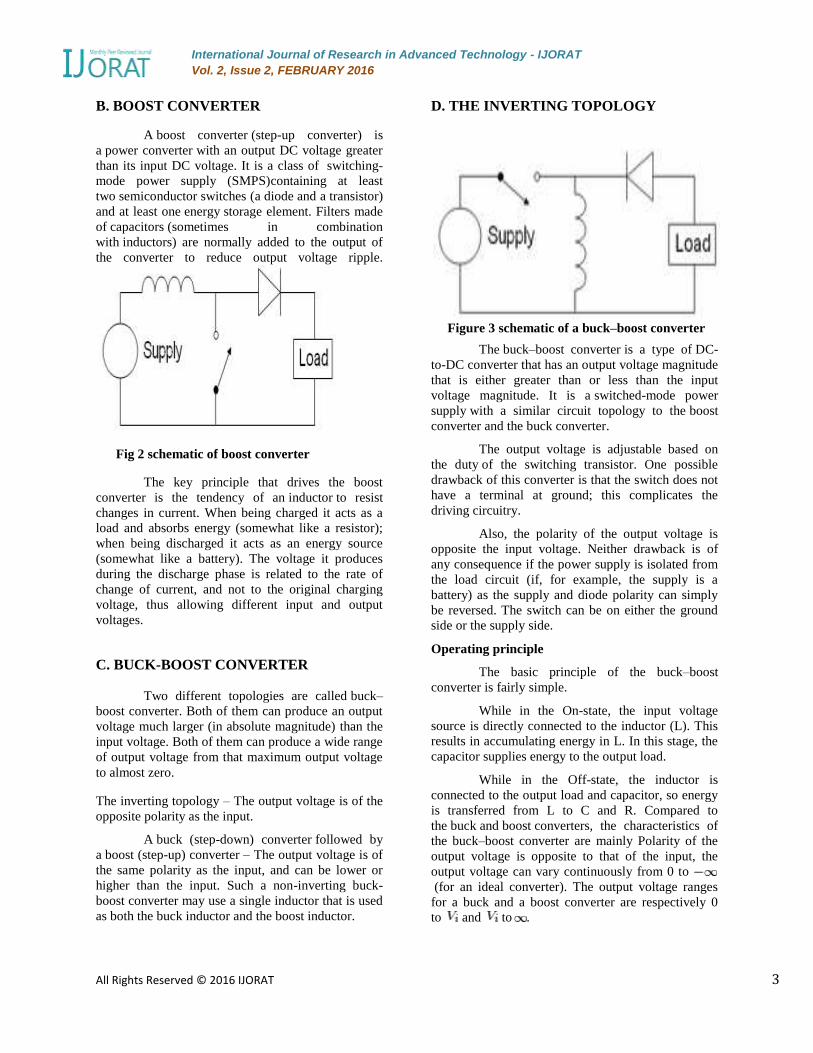
B. BOOST CONVERTER
A boost converter (step-up converter) is
a power converter with an output DC voltage greater
than its input DC voltage. It is a class of switching-
mode power supply (SMPS)containing at least
two semiconductor switches (a diode and a transistor)
and at least one energy storage element. Filters made
of capacitors (sometimes in combination
with inductors) are normally added to the output of
the converter to reduce output voltage ripple.
Fig 2 schematic of boost converter
The key principle that drives the boost
converter is the tendency of an inductor to resist
changes in current. When being charged it acts as a
load and absorbs energy (somewhat like a resistor);
when being discharged it acts as an energy source
(somewhat like a battery). The voltage it produces
during the discharge phase is related to the rate of
change of current, and not to the original charging
voltage, thus allowing different input and output
voltages.
C. BUCK-BOOST CONVERTER
Two different topologies are called buck–
boost converter. Both of them can produce an output
voltage much larger (in absolute magnitude) than the
input voltage. Both of them can produce a wide range
of output voltage from that maximum output voltage
to almost zero.
The inverting topology – The output voltage is of the
opposite polarity as the input.
A buck (step-down) converter followed by
a boost (step-up) converter – The output voltage is of
the same polarity as the input, and can be lower or
higher than the input. Such a non-inverting buck-
boost converter may use a single inductor that is used
as both the buck inductor and the boost inductor.
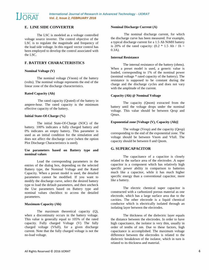
D. THE INVERTING TOPOLOGY
Figure 3 schematic of a buck–boost converter
The buck–boost converter is a type of DC-
to-DC converter that has an output voltage magnitude
that is either greater than or less than the input
voltage magnitude. It is a switched-mode power
supply with a similar circuit topology to the boost
converter and the buck converter.
The output voltage is adjustable based on
the duty of the switching transistor. One possible
drawback of this converter is that the switch does not
have a terminal at ground; this complicates the
driving circuitry.
Also, the polarity of the output voltage is
opposite the input voltage. Neither drawback is of
any consequence if the power supply is isolated from
the load circuit (if, for example, the supply is a
battery) as the supply and diode polarity can simply
be reversed. The switch can be on either the ground
side or the supply side.
Operating principle
The basic principle of the buck–boost
converter is fairly simple.
While in the On-state, the input voltage
source is directly connected to the inductor (L). This
results in accumulating energy in L. In this stage, the
capacitor supplies energy to the output load.
While in the Off-state, the inductor is
connected to the output load and capacitor, so energy
is transferred from L to C and R. Compared to
the buck and boost converters, the characteristics of
the buck–boost converter are mainly Polarity of the
output voltage is opposite to that of the input, the
output voltage can vary continuously from 0 to
(for an ideal converter). The output voltage ranges
for a buck and a boost converter are respectively 0
to and to .
International Journal of Research in Advanced Technology - IJORAT Vol. 2, Issue 2, FEBRUARY 2016
All Rights Reserved © 2016 IJORAT 4
E. LINE SIDE CONVERTER
The LSC is modeled as a voltage controlled
voltage source inverter. The control objective of the
LSC is to regulate the magnitude and frequency of
the load side voltage. In this regard vector control has
been employed to develop the control associated with
the LSC.
F. BATTERY CHARACTERISTICS
Nominal Voltage (V)
The nominal voltage (Vnom) of the battery
(volts). The nominal voltage represents the end of the
linear zone of the discharge characteristics.
Rated Capacity (Ah)
The rated capacity (Qrated) of the battery in
ampere-hour. The rated capacity is the minimum
effective capacity of the battery.
Initial State-Of-Charge (%)
The initial State-Of-Charge (SOC) of the
battery. 100% indicates a fully charged battery and
0% indicates an empty battery. This parameter is
used as an initial condition for the simulation and
does not affect the discharge curve (when the option
Plot Discharge Characteristics is used).
Use parameters based on Battery type and
nominal values
Load the corresponding parameters in the
entries of the dialog box, depending on the selected
Battery type, the Nominal Voltage and the Rated
Capacity. When a preset model is used, the detailed
parameters cannot be modified. If you want to
modify the discharge curve, select the desired battery
type to load the default parameters, and then uncheck
the Use parameters based on Battery type and
nominal values checkbox to access the detailed
parameters.
Maximum Capacity (Ah)
The maximum theoretical capacity (Q),
when a discontinuity occurs in the battery voltage.
This value is generally equal to 105% of the rated
capacity. Fully charged Voltage (V) The fully
charged voltage (Vfull), for a given discharge
current. Note that the fully charged voltage is not the
no-load voltage.
Nominal Discharge Current (A)
The nominal discharge current, for which
the discharge curve has been measured. For example,
a typical discharge current for a 1.5 Ah NiMH battery
is 20% of the rated capacity: (0.2 * 1.5 Ah / 1h =
0.3A).
Internal Resistance
The internal resistance of the battery (ohms).
When a preset model is used, a generic value is
loaded, corresponding to 1% of the nominal power
(nominal voltage * rated capacity of the battery). The
resistance is supposed to be constant during the
charge and the discharge cycles and does not vary
with the amplitude of the current.
Capacity (Ah) @ Nominal Voltage
The capacity (Qnom) extracted from the
battery until the voltage drops under the nominal
voltage. This value should be between Qexp and
Qmax.
Exponential zone [Voltage (V), Capacity (Ah)]
The voltage (Vexp) and the capacity (Qexp)
corresponding to the end of the exponential zone. The
voltage should be between Vnom and Vfull. The
capacity should be between 0 and Qnom.
G. SUPERCAPACITOR
The capacitance of a capacitor is closely
related to the surface area of the electrodes .A super
capacitor is a component which has relatively high
specific power ability in comparison to batteries
much like a capacitor, while it has much higher
specific energy than a conventional capacitor, more
like a battery.
The electric chemical super capacitor is
constructed with a carbonized porous material as one
electrode, which has a large surface area due to the
cavities. The other electrode is a liquid chemical
conductor which is electrically isolated through an
isolating layer between the electrodes.
The thickness of the dielectric layer equals
the distance between the electrodes. In order to have
high capacitance, the isolator is very thin, usually in
order of tenths of nm. Due to these factors, high
capacitance is accomplished. The maximum voltage
difference between the electrodes is related to the
dielectric breakdown of the isolator, which in turn is
related to its thickness and material.

International Journal of Research in Advanced Technology - IJORAT Vol. 2, Issue 2, FEBRUARY 2016
All Rights Reserved © 2016 IJORAT 5
H. SIMULATION OF PROPOSED
SYSTEM The energy management algorithm applied
for both storage options have been developed to
satisfy the above-stated objectives. The energy
management algorithm for the battery storage and
super capacitor is depicted. The input signal to the
energy management algorithm is selected as the
demand-generation mismatch with a view to achieve
the first objective. To realize the second objective,
the demand-generation mismatch is estimated. The
application of energy storage to a standalone power
system can be used to fulfill one or more of the
following requirements: (1) to improve the efficiency
of the entire RAPS system, (2) to reduce the primary
fuel (e.g., diesel) usage by energy conversion, and (3)
to provide better security of energy supply. The
justification behind the integration of energy storage
into a wind energy application is based on the factors
which include total wind turbine inertia, low voltage
ride through capability, power quality issues, etc...For
a wind turbine based RAPS system, an ideal ESS
should be able to provide both high energy and power
capacity to handle situations such as wind gust or
sudden load variations which may exist for a few
seconds or even longer.
Fig 4 Simulink model of proposed system
. Permanent Magnet Synchronous Generator
(PMSG) offers many advantages but not limited to
self excitation capability which allows operation at a
high power factor and improved efficiency, gear-less
transmission, high reliability, good control
performance, Maximum Power Point Tracking
(MPPT) capability, low noise emissions, etc.. The
performance of the components of a hybrid RAPS
system is investigated under fluctuating wind and
variable load conditions. The PMSG performs as the
main source of energy while the hybrid energy
storage together with the dump load perform as
auxiliary system components to maintain the active
power balance of the RAPS system and to extract the
maximum power from wind.
An isolated operation of a PMSG with a
battery storage system is only covers a RAPS system
consisting of PMSG and battery storage. A multilevel
energy storage consisting of flow battery storage and
a super capacitor is explained. Different control
strategies proposed for the battery-super capacitor
hybrid energy storage system. It only examines the
different control strategies that could be applied to a
hybrid energy storage system. In an optimal energy
management scheme for battery-super capacitor
hybrid energy storage. In order to obtain the optimal
solution, have formulated the problem as an
optimization problem for minimization of the
fluctuation of the current flowing in and out of the
battery and the energy loss seen by the super
capacitor.
However, optimization is generally
application-oriented and the optimized parameters for
one system may not be suitable for another. a power
sharing strategy is formulated for battery energy
storage and super capacitor based on the demand-
generation variations of the RAPS system.
Fig 5 waveform for supercapacitor voltage
0 0.05 0.1 0.15 0.2 0.25 0.3 0.35 0.420
30
40
50
60
70
80
Time (sec)
vol (v)
<Voltage V>

International Journal of Research in Advanced Technology - IJORAT Vol. 2, Issue 2, FEBRUARY 2016
All Rights Reserved © 2016 IJORAT 6
This figure shows the output voltage of
supercapacitor during under generation condition.
Fig 6 waveform for supercapacitor current
This fig shows output current of the
supercapacitor during low or no generation
Fig 7 waveform for supercapacitor power
This figure represents the output for
supercapacitor during under generation condition
where the supercapacitor delivers the power to the
load.
Fig 8 waveform for battery current
This fig shows the output of the battery current is
delivered to the load.
Fig 9 waveform for soc of supercapacitor
Fig 9 shows the state of charging level of the
supercapacitor during over generation condition.
Fig 10 waveform for frequency regulation
This figure represents the output for
frequency regulation at load side. The operating
frequency of the system is regulated with in rated
value.
Fig 11 waveform for load voltage
This figure shows the output for load
voltage during both over generation and under
generation condition. Here we can achieve the three
phase 400V supply.
0 0.05 0.1 0.15 0.2 0.25 0.3 0.35 0.4-3
-2.5
-2
-1.5
-1
-0.5
0
0.5x 10
4
Time (sec)
current (A
)<Current I>
0 0.05 0.1 0.15 0.2 0.25 0.3 0.35 0.4-2.5
-2
-1.5
-1
-0.5
0
0.5x 10
6
Time (sec)
pow
er
0 0.05 0.1 0.15 0.2 0.25 0.3 0.35 0.4-2000
-1500
-1000
-500
0
500
Time(sec)
current(A
)
<Current (A)>
0 0.05 0.1 0.15 0.2 0.25 0.3 0.35 0.430
40
50
60
70
80
90
100
110
Time (sec)
voltage (v)
<SOC %>
0 0.05 0.1 0.15 0.2 0.25 0.3 0.35 0.450
50.005
50.01
50.015
50.02
50.025
50.03
50.035
Time (sec)
freq (
Hz)
0 0.05 0.1 0.15 0.2 0.25 0.3 0.35 0.4-400
-300
-200
-100
0
100
200
300
400
Time (sec)
voltage (v)
Vload

International Journal of Research in Advanced Technology - IJORAT Vol. 2, Issue 2, FEBRUARY 2016
All Rights Reserved © 2016 IJORAT 7
Fig 12 waveform for load current
Fig 12 represents the output for load current.
Here we can get the 15A current.
Fig 13 waveform for load power
This figure shows the load power during
both over generation and under generation condition.
Also, the sudden wind speed changes cause rapid
variations of the wind power output.
CONCLUSION
The proposed standalone operation of
PMSG with hybrid energy storage system includes a
wind turbine which takes up the wind speed. The
mechanical output of the wind turbine is then
transmitted to the PMSG. The AC output of the
generator is then converted to DC by means of a
rectifier. The rectified output of the generator is then
boosted up by a boost converter. The output of boost
converter is fed to the inverter to make it suitable for
further connection of system to load. The hybrid
energy storage system is connected between rectifier
and inverter for improving the power balance of the
entire remote area power supply system. The energy
management algorithm is proposed for hybrid energy
storage system with a view to improve the
performance of the battery.The main focus of this
paper is on proposing an effective management of
hybrid energy storage system and to obtain the robust
voltage and frequency regulation.
Further work could be accomplished by
means of implementing a storage system to ensure
constantpower output to the load.
ACKNOWLEDGMENT
First of all we would like to thank the
almighty for giving me sound health throughout my
paper work. This research was supported/partially
supported by our college. We thank our staffs from
our department who provided insight and expertise
that greatly assisted the research, although they may
not agree with all of the interpretations/conclusions
of this paper.
REFERENCES
[1] C. Abbey and G. Joos, “Supercapacitor
energy storage for wind energy
applications,” IEEE Trans. Ind. Appl.,
vol. 43, no. 3, pp. 769–776,May-Jun.
2007.
[2] C. Abbey and G. Joos, “Short-term
energy storage for wind energy
applications,” in Proc. Ind. Appl. Soc.
Annu.Meet., Hong Kong, China, Oct.
2–6, 2005, vol. 3, pp. 2035–2042.
[3] M. Choi, S. Kim, and S. Seo, “Energy
management optimization in a
battery/supercapacitor hybrid energy
storage system,” IEEE Trans. Smart
Grid, vol. 3, pp. 463–472, Feb. 2012.
[4] M. Gee, F. V. P. Robinson, and R. W.
Dunn, “Analysis of battery lifetime
extension in a small-scale wind-energy
system using supercapacitors,” IEEE
Trans. Energy Converts., vol. 3, pp.
24–33, Feb. 2013.
[5] L. Harnefors and H. P. Nee, “Model-
based current control of AC machines
Using the internal model control
method,” IEEE Trans. Ind. Appl., vol.
34, pp. 133–141, Jan./Feb. 1998.
[6] M. E. Haque, M. Negnevitsky, and K.
M. Muttaqi, “A novel control strategy
for a variable-speed wind turbine with
permanent-magnet synchronous
generator,” IEEE Trans. Ind. Appl.,
vol. 46, pp. 331–339, Nov. 2009.
[7] H. Jia, Y. Fu, Y. Zhang, and W. He,
“A design of hybrid energy storage
0 0.05 0.1 0.15 0.2 0.25 0.3 0.35 0.4-15
-10
-5
0
5
10
15
Time (sec)
current (A
)
Vload
0 0.05 0.1 0.15 0.2 0.25 0.3 0.35 0.4-500
0
500
1000
1500
2000
2500
3000
3500
Time (sec)
pow
er (kw
)
Vload

International Journal of Research in Advanced Technology - IJORAT Vol. 2, Issue 2, FEBRUARY 2016
All Rights Reserved © 2016 IJORAT 8
control system for wind farms based on
flow battery and electric double-layer
capacitor,” in Proc. Asia-Pacific Power
Energy Eng. Conf. (APPEEC),
Chengdu, China, Mar. 28–31, 2010,
pp. 1–6.
[8] F. Liu, J. Liu, and L. Zhou, “A novel
control strategy for hybrid energy
storage system to relieve battery
stress,” in Proc. Int. Symp. Power
Electron. Distribute. Gener. Syst.
(PEDG), Hefei, China, Jun. 16–18,
2010, pp. 929–934.
[9] N. Mendis, K. M. Muttaqi, S. Sayeef,
and S. Perera, “A control approach for
voltage and frequency regulation of a
wind-diesel-battery based hybrid
remote area power supply systems,” in
Proc. 36th Annu. Conf. IEEE Ind.
Electron. Soc., Glendale, AZ, USA,
Nov. 10, 2010, pp. 3054–3060.
[10] N. Mendis, K. Muttaqi, S. Perera, and
M. N. Uddin, “A novel control strategy
for stand-alone operation of a wind
dominated RAPS system,”in Proc.
IEEE Ind. Appl. Soc. (IAS) Annu.
Meet., Orlando, FL, USA, Oct. 9–13,
2011.
[11] S. Sayeef, N. Mendis, and K. Muttaqi,
“Enhanced reactive power support of a
PMSG based wind turbine for a remote
area power system,” in Proc. 20th
Australian Power Eng. Conf.
(AUPEC2010), Christchurch, New
Zealand, Dec. 5–8, 2010, pp. 1–5.
[12] M. Singh and A. Chandra, “Control of
PMSG based variable-speed wind-
battery hybrid system in an isolated
network,” in Proc. Power Energy Soc.
Gen. Meet. (PESGM), Calgary, AB,
Canada, Jul. 26–30, 2009, pp. 1–6.
[13] A. M. v. Voorden, L. M. R. Elizondo,
G. C. Paap, J. Verboomen, and L. v. d.
Sluis, “The application of super
capacitors to relieve battery storage
systems in autonomous renewable
energy systems,” in Proc. Power Tec,
Lausanne, Switzerland, Jul. 1–5, 2007,
pp. 479–484.
[14] L. Wei and G. Joos, “A power
electronic interface for a battery
supercapacitor hybrid energy storage
system for wind applications,” in Proc.
Power Electron. Specialists Conf.,
Rhodes, Greece, Jun. 15–19, 2008, pp.
1762–1768.
[15] L. Wei, G. Joos, and J. Bélanger,
“Real-time simulation of a wind
turbine generator coupled with a
battery supercapacitor energy storage
system,” IEEE Trans. Ind. Electron.,
vol. 75, no. 4, pp. 1137–1145, Apr.
2010.