PUNJAB BEVEL GEARS. INTRODUCTION Sahibabad SitarganjSahibabad.

ISO Standardisation of Bevel Gears:
Overview and Ideas on Method „A“
Dr. Joachim Thomas, ZG Hypoid GmbH

Dr. J. Thomas
Slide 2
09.02.2018 Content
1. ISO Standardisation of Bevel Gear
2. Calculation Methods B…C
3. Example Calculation
4. Conclusions

Dr. J. Thomas
Slide 3
09.02.2018 1. ISO Standardisation of Bevel Gears
ISO/TC60/SC2: Gear Capacity Calc.
International Standard Organisation ISO
TC 60 Technical Committee: Gears
Sekretariat: ANSI
Chairperson: Thomas Maiuri
SC 1 Sub Committee: Nomenclature & Worm Gearing
Sekretariat: BSI
Chairperson : Dr. Paul Bradley
SC 2 Sub Committee: Gear Capacity Calculation
Sekretariat: DIN
Chairperson : Dr. Ralf Möllendorf

Dr. J. Thomas
Slide 4
09.02.2018 1. ISO Standardisation of Bevel Gears
ISO/TC60/SC2/WG13: Bevel Gears
WG 13 Working Group: Bevel Gears
Chairperson: Dr. Joachim Thomas
Delegates:
USA: Claus Weyand, Amir Aboutaleb (AGMA)
UK: N.N.
Japan: Ryohei Takeda
Finland: Jesse Rontu
Switzerland: Jürg Langhart
Germany: Dr. Ralf Hess, Rudolf Houben,
Josef Pellkofer, N.N. (DIN / VDMA)

Dr. J. Thomas
Slide 5
09.02.2018 1. ISO Standardisation of Bevel Gears
Load Capacity Calc. of Bevel Gears
DIN 3991 (1988) AGMA 2003 (A86)
ISO 10300 (2001)
AGMA 2003 (B97)
ISO 10300 (2014?)
ISO 23509 (2004)
for calculation of non
offset bevel gears only
Geometry
calculation of
bevel and
Hypoid gears
calculation of bevel and
Hypoid gears
ISO TC60/SC2/WG13
FVA 411

Dr. J. Thomas
Slide 6
09.02.2018 1. ISO Standardisation of Bevel Gears
Load Capacity Calc. of Bevel Gears
ISO/TR 22489 (2011)
AGMA 2005
ISO 17485 (2006)
Technical Report: Design
recommendations for bevel
gears
Tolerances for bevel and
Hypoid gears
ISO TC60/SC2/WG13
...
Additional standards resp. recommendations:
ISO 1328 DIN 3961
ISO TC60/SC1/WG2 (Ad hoc: Bevel Gears)

Dr. J. Thomas
Slide 7
09.02.2018 1. ISO Standardisation of Bevel Gears
Load Capacity Calc. of Bevel Gears
Examples to part 1…3
Scuffing
valid
ISO 10300-1 (2014)
Micropitting
Flank fracture
ISO 10300-2 (2014)
ISO 10300-3 (2014)
ISO/TS 10300-20
ISO/TS 10300-22
ISO/TS 10300-4
Introduction and general influence factors
Calculation of surface durability (pitting)
Calculation of tooth root strength
ISO/TR 10300-30
Scuffing examples ISO/TR 10300-32
in progress planed
Fatigue
T
ribolo
gy
Exam
ple
s

Dr. J. Thomas
Slide 8
09.02.2018 1. ISO Standardisation of Bevel Gears
Methods within Standard
• ISO 10300 contains methods B and for some factors method C.
• It always is a target, to advance the methods to come nearer to method A as
good as possible.
• It always is allowed to calculate even some individual factors according to a
higher method, if available. Of course there always is the difficulty, if such a
higher method is accepted by customers and business partners.
• Question: How near is Method B1 of ISO 10300 to Method A?
Method A
…
Method B
Method C
Method D…
the most precise and high-grade calculation method, or
proved load capacity on real parts, per example by
measurements (of stresses).
the best (simplified) calculation method
a more simplified calculation method

Dr. J. Thomas
Slide 9
09.02.2018 Content
1. ISO Standardisation of Bevel Gear
2. Calculation Methods B…C
3. Example Calculation
4. Conclusions

Dr. J. Thomas
Slide 10
09.02.2018 2. Calculation Methods B…C
Safety Factors
min,
2,1
2,1
2,1 H
H
HP
HSS
SH : Safety factor for contact stress
σHP : Allowable contact stress
σH : Contact stress
SH, min : Minimal safety factor of contact stress
min,
2,1
2,1
2,1 F
F
FP
FSS
SF : Safety factor of tooth root stress
σFP : Allowable tooth root stress
σF : Tooth root stress
SF, min : minimal safety factor of tooth root stress

Dr. J. Thomas
Slide 11
09.02.2018 2. Calculation Methods B…C
Stresses
a) : Forces, Geometry
b) : (Geometrical) influence factors
c) : Force factors
ZK : bevel gear factor = 0,85
b) a) b)
a) c) b)
Method B1
KZ
HK
HK
VK
AK
BMZ
LSZ
EZ
ersbml
nF
H
Method B1
FFVALSBSSaFa
mnv
vmt
FKKKKYYYYY
mb
F
2,12,12,1
Influence of load carrying face width and lengthwise crowning resp.
Dr. J. Thomas
Slide 12
09.02.2018 2. Calculation Methods B…C
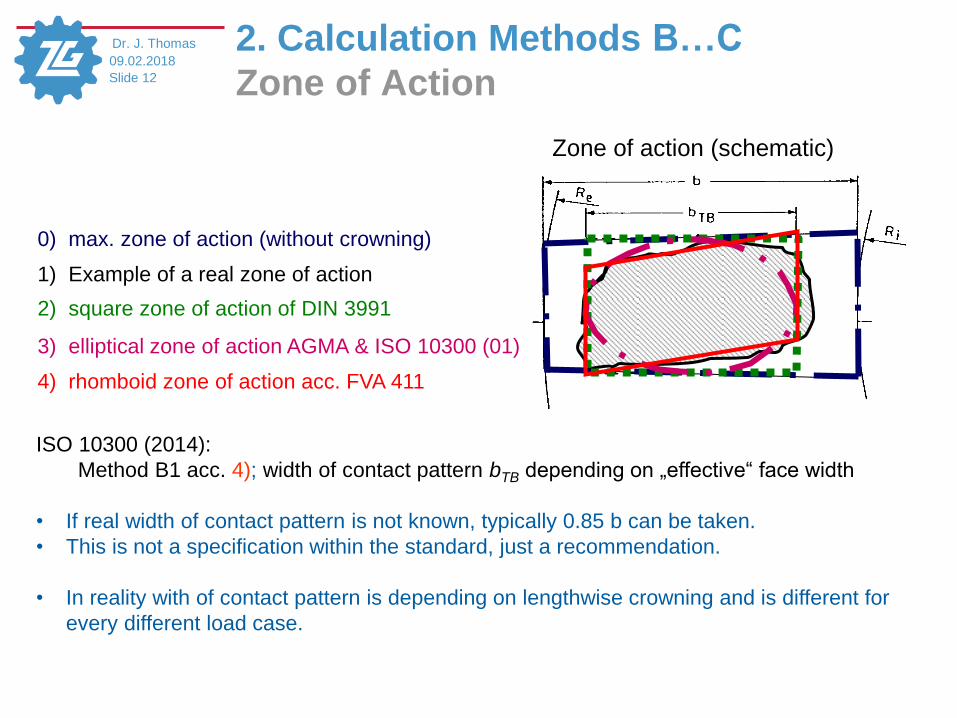
Zone of Action
0) max. zone of action (without crowning)
1) Example of a real zone of action
2) square zone of action of DIN 3991
3) elliptical zone of action AGMA & ISO 10300 (01)
4) rhomboid zone of action acc. FVA 411
ISO 10300 (2014):
Method B1 acc. 4); width of contact pattern bTB depending on „effective“ face width
• If real width of contact pattern is not known, typically 0.85 b can be taken.
• This is not a specification within the standard, just a recommendation.
• In reality with of contact pattern is depending on lengthwise crowning and is different for
every different load case.
Zone of action (schematic)

Dr. J. Thomas
Slide 13
09.02.2018 2. Calculation Methods B…C
Force Factors
H αH βVAKKKK for surface durability (pitting)
FFVAKKKK for tooth root strength
KA : Application Factor
KV : Dynamic Factor
KH, KF : Face Load Factors
KH, KF : Transverse Load Factors

Dr. J. Thomas
Slide 14
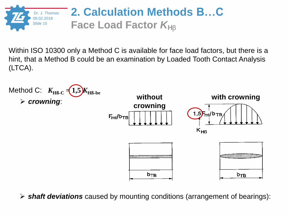
09.02.2018 2. Calculation Methods B…C Face Load Factor KH
The Face Load Factor KH considers uneven load distribution on the flank.
Definition:
wmax: maximum line load wm: mean line load, related to length of contact line
decisive calculation point
m
H
w
wK
max
wm
wmax
Dr. J. Thomas
Slide 15
09.02.2018 2. Calculation Methods B…C Face Load Factor KH
without
crowning
with crowning
Within ISO 10300 only a Method C is available for face load factors, but there is a
hint, that a Method B could be an examination by Loaded Tooth Contact Analysis
(LTCA).
Method C: KHß-C = 1,5 KHß-be
crowning:
shaft deviations caused by mounting conditions (arrangement of bearings):

Dr. J. Thomas
Slide 16
09.02.2018 2. Calculation Methods B…C Mounting Factor KHbe
The Mounting Factor KHb-be considers displacement of gear and pinion under load
caused by the arrangement of bearings
Verification of contact
pattern Mounting conditions of pinion and gear
Contact pattern is checked: both straddle
mounted
one cantilever -
one straddle mounted
both cantilever
mounted
For each gear set in its carrier
under full load 1.00 1.00 1.00
For each gear set under light
test load 1.05 1.10 1.25
For a sample gear set and
estimated for full load 1.20 1.32 1.50
Note: Based on optimum tooth contact pattern under maximum operating load
as evidenced by results of a deflection test on the gears in their respective mountings.
KHß-C = 1,5 ∙ 1,1 = 1,65
Often taken value for calculation acc. ISO 10300:

Dr. J. Thomas
Slide 17
09.02.2018 2. Calculation Methods B…C Face Load Factor KF
The Face Load Factor KF considers uneven stress distribution on the tooth root.
Definition:
σFmax: maximum tooth root stress σFm: mean tooth root stress
Fm
F
BSFYK
max
σmax
σm

Dr. J. Thomas
Slide 18
09.02.2018 2. Calculation Methods B…C Face Load Factor KF
Within ISO 10300 only a Method C is available for face load factors, but there is a
hint, that a Method B could be an examination by Loaded Tooth Contact Analysis
(LTCA).
Method C: KFß-C = KHß-C / KF0
with KF0: Lengthwise curvature factor
“The lengthwise curvature factor KF0 considers the contact pattern shift under different
loads which is smallest, if the lengthwise tooth curvature at the mean point
corresponds to that of an involute curve. This effect is well known and depends on
the cutter radius rc0 and the spiral angle βm2.” (Source: ISO 10300-1 (2014)).
1,00 ≤ KF0 ≤ 1,15: That means, that maximum effect of small tool radius is 15%.

Dr. J. Thomas
Slide 19
09.02.2018 Content
1. ISO Standardisation of Bevel Gear
2. Calculation Methods B…C
3. Example Calculation
4. Conclusions

Dr. J. Thomas
Slide 20
09.02.2018 3. Example Calculation
Gear and Load Data

Dr. J. Thomas
Slide 21
09.02.2018 3. Example Calculation
ISO10300 Method B(C)
Input for first calculation acc. to ISO 10300 (Method B1):
Rel. contact width: beff = 0,85 b
Mounting factor: KHß-be = 1,1
Method C => KHß-C = 1,65
Method C => KFß-C = 1,435 with KF0 = 1,15
Results:

Dr. J. Thomas
Slide 22
09.02.2018 3. Example Calculation Becal*) LTCA – comp. to ISO (Method B/C)
Pinion Gear
σH_ISO / ZK = 2796,86 MPa ISO (Meth. B/C):
ISO (Meth. B/C): σF1_ISO = 1296,36 MPa σF2_ISO = 1412,79 MPa
*) Becal is a software tool by FVA e.V. (Forschungsvereinigung Antriebstechnik – Research Association for Drive Technology)

Dr. J. Thomas
Slide 23
09.02.2018
Load distribution
3. Example Calculation Face Load Factors Method B
KHß= wmax / wm = 1,49
KFß1 ∙ YBS = σF1max / σF1m = 3,44 KFß2 ∙ YBS = σF2max / σF2m = 2,99
beff
b
beff / b = 0,90
Pinion Gear

Dr. J. Thomas
Slide 24
09.02.2018 3. Example Calculation ISO10300 Methode B(B)
Input for second calculation acc. ISO 10300:
Rel. contact width: beff = 0,90 b
Face Load factors (Method B): KHß-B = 1,49
KFß1-B = 1,67 KFß2-B = 1,45
with YBS = 2,06
Results:

Dr. J. Thomas
Slide 25
09.02.2018 3. Example Calculation Becal*) LTCA – comp. to ISO (Method B/B)
Pinion Gear
σH_ISO / ZK = 2534,09 MPa
ISO (Meth. B/B): σF1_ISO = 1362,76 MPa σF2_ISO = 1315,29 MPa
ISO (Meth. B/B):
*) Becal is a software tool by FVA e.V. (Forschungsvereinigung Antriebstechnik – Research Association for Drive Technology)

Dr. J. Thomas
Slide 26
09.02.2018 Content
1. ISO Standardisation of Bevel Gear
2. Calculation Methods B…C
3. Example Calculation
4. Conclusions

Dr. J. Thomas
Slide 27
09.02.2018 4. Conclusions
• Within the series of standards ISO10300 for the load carrying capacity calculation of
bevel gears actually are covered standards for the tooth flank (pitting) and tooth
root capacity. There are available specifications for scuffing calculation as well as
technical reports for sample calculations. Additional parts will be added
continuously.
• The actual standards include quite rough influences of lengthwise crowning only
(Method C). This lead to obvious differences in comparison to results according to
superior calculation methods, like loaded tooth contact analysis (LTCA).
• As soon as results according to LTCA (Method B) are introduced into ISO10300, the
differences in final results are (negligible?) low and a proof of load carrying
capacity according ISO10300 is possible.
• If LTCA calculation software packages have been proved by measurements on real
bevel gears, these methods actually are most near to reality (Method A) according
to actual state of knowledge.

Dr. J. Thomas
Slide 28
09.02.2018
Thank you for your
attention!
![85540168 Bevel Gears in ProE[1]](https://static.fdocuments.in/doc/165x107/544b2fd6b1af9f804f8b4fca/85540168-bevel-gears-in-proe1.jpg)


![Bevel Gears in ProE[1]](https://static.fdocuments.in/doc/165x107/543da9fbb1af9f3d0a8b4920/bevel-gears-in-proe1.jpg)