ISO Registered Company PREMIER EZOcashco.s3.amazonaws.com/2017/11/07/21/51/56/22/Premier_TB.pdf ·...
15
TECHNICAL BULLETIN Premier-TB 02-16 PREMIER EZO BUTTERFLY ROTARY CONTROL VALVE The Premier EZO is an elastomer lined concentric butterfly control valve with a pneumatic spring-diaphragm actuator. The unique design feature of the Premier EZO is the geometrically formed elastomer liner that reduces seating and unseating torque levels, allowing E Z-er Opening, reducing annoying “pop-off” at opening. An alternate design – Premier Unlined – is a seatless design that allows the disc 360 degree rotation, that has no elastomer liner and can be applied in higher temperature services where shutoff is not critical. Both designs are for low-to-moderate pressure drop throttling applications. Installation is between piping flanges as a flangeless wafer. (NOTE: Premier EZO must be installed between RF weldneck flanges.) FEATURES • Five sizes; 3” - 10” (DN80 - 250) • Flangeless wafer body • Three body materials • Two elastomer liner materials • Integral extended bonnet • Heavy stem guides • Low pressure actuator package designed for throttling APPLICATIONS Primarily applied in non-critical utility applications such as compressed air or gas, cooling water, chilled water, hot water, or some HC services for Premier EZO. Premier Unlined is primarily applied in steam and hot gas, including HC services. PREMIER EZO LINED BUTTERFLY CONTROL VALVE ISO Registered Company
Transcript of ISO Registered Company PREMIER EZOcashco.s3.amazonaws.com/2017/11/07/21/51/56/22/Premier_TB.pdf ·...
TECHNICAL BULLETIN Premier-TB02-16
PREMIER EZOBUTTERFLY ROTARY CONTROL VALVE
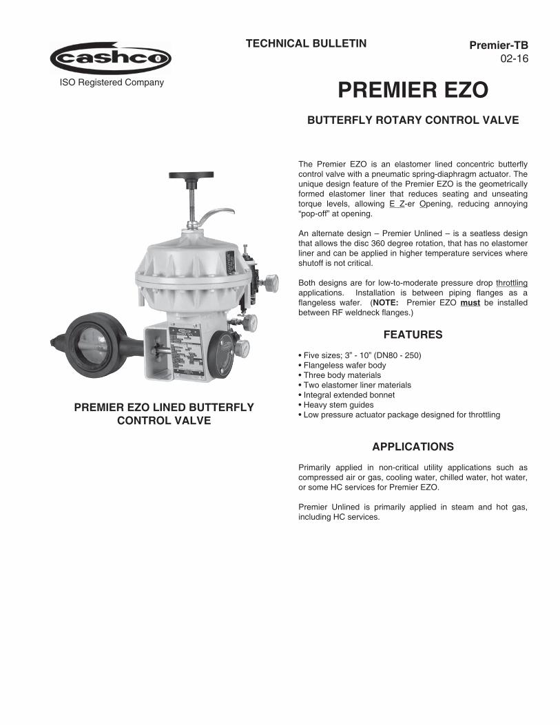
The Premier EZO is an elastomer lined concentric butterfly control valve with a pneumatic spring-diaphragm actuator. The unique design feature of the Premier EZO is the geometrically formed elastomer liner that reduces seating and unseating torque levels, allowing E Z-er Opening, reducing annoying “pop-off” at opening.
An alternate design – Premier Unlined – is a seatless design that allows the disc 360 degree rotation, that has no elastomer liner and can be applied in higher temperature services where shutoff is not critical.
Both designs are for low-to-moderate pressure drop throttling applications. Installation is between piping flanges as a flangeless wafer. (NOTE: Premier EZO must be installed between RF weldneck flanges.)
FEATURES
• Five sizes; 3” - 10” (DN80 - 250)• Flangeless wafer body• Three body materials• Two elastomer liner materials• Integral extended bonnet• Heavy stem guides• Low pressure actuator package designed for throttling
APPLICATIONS
Primarily applied in non-critical utility applications such as compressed air or gas, cooling water, chilled water, hot water, or some HC services for Premier EZO.
Premier Unlined is primarily applied in steam and hot gas, including HC services.
PREMIER EZO LINED BUTTERFLY CONTROL VALVE
ISO Registered Company
2 Premier-TB
STANDARD/GENERAL SPECIFICATIONS
Body Design Type: Concentric butterfly-type; 90° rotation. Flangeless wafer-type for mounting between pipe flanges.
Premier EZO - includes elastomer liner.
Premier Unlined - no elastomer liner.
Body Sizes: 3”, 4”, 6”, 8” and 10”. (DN80, 100, 150, 200 and 250.)
Body Materials: CI - Cast Iron CS - Cast Steel SST - Cast 316 SST See Table 1 for material specifications.
Elastomer Liner Premier EZO ONLY. Materials: Backup ring - hard synthetic rubber. Seat and flange face - Buna-N (Nitrile), EPDM (Ethylene propylene).
Body Pressure/ See Table 1. Dependent on body Temperature material - Rating: CI - ANSI 125 #. CS & SST - ANSI 150 # / 300 #.
Body Face-to Face Per MSS- SP67. See Figures 4 and 5 Dimensions: for dimensions
Maximum Body CI - per ANSI B16.1. Pressure: CS & SST - per ANSI B16.34. See Table 1. CI - 200 psig (13.8 Barg). CS - 740 psig (51.0 Barg). SST - 720 psig (49.6 Barg).
Maximum Shutoff Premier EZO - 150 psid (10.3 Bard). Pressure Drop: Premier Unlined - Function of body size. Up to 300 psid (20.7 Bard). See Table 2.
Maximum Dynamic Function of degrees rotation, actuator Pressure Drop: size, shaft material, body size, and internal velocity. See Tables 3A & 3B for limitations expressed as a pressure drop.
Minimum Body Premier EZO - Partial vacuum down Pressure: to 0.5 psia (0.035 BarA). Premier Unlined - Full vacuum 0.0 psia (0.0 BarA).
Maximum Body Function of body material and liner Temperature: material. Premier EZO - Buna-N liner: CI, CS, SST: +180° F (83° C) Premier EZO - EPDM liner: CI, CS, SST: +250° F (122° C)
Premier Unlined: CI - 450° F (232° C) CS & SST - 500° F (260° C)
Minimum Body Function of liner material. Temperature: Premier EZO - Buna-N liner: CI, CS, SST: +10° F (-12° C) Premier EZO - EPDM liner: CI, CS, SST: -20° F (-29° C)
Premier Unlined: -20° F (-29° C)
Flow Direction: Bi-directional; 0-90° rotation.
Inherent Equal Percentage. Characteristic:
Seat Leakage Per ANSI/FCI 70-2 @ ∆P min ≥ 50 psid Class: (3.45 Bard).
Premier EZO - Class VI. Premier Unlined - Class I; i.e. 1% Max Cv. Rangeability: 100:1
Maximum Cv Capacity:
Clamping Premier EZO - CS or SST weldneck Companion flanges ONLY, RF or FF, pressure Flanges: classes 150 # or 300 #; NO CI 125 # or 250 # pipe flanges.
Premier Unlined - CS or SST flanges, RF or FF, pressure classes 150 # or 300 #; CI 125 # FF or 250 # RF flanges.
Body Size Cv Capacity
In. (DN) Premier EZO
Premier Unlined
3”4”6”
(80)(100)(150)
179522
1021
243670
1345
8”10”
(200)(250)
25903815
34594406
NOTE: Metric Capacity Factor - KvKv = Cv/1.16
Premier-TB 3
Stem Diameter:
Flange Surface Premier EZO - Not applicable. NO pipe Finish: flange gaskets to be utilized. Premier Unlined - 250/125 micro-inch Ra (equivalent to 250/125 AARH). Suitable for use with spiral-wound metallic-filled gaskets.
Body Size Stem Diameter
In. (DN) In. (mm)
3” & 4”6”-10”
(80 & 100)(150-250)
0.625”1.000”
(15.9)(25.4)
Painting: Standard: All non-corrosion resistant portions to be painted with corrosion resistant epoxy paint per Cashco Spec #S-1606.
Alternate: See Opt-95.
BODY SUB-ASSEMBLY MATERIAL SPECIFICATIONS
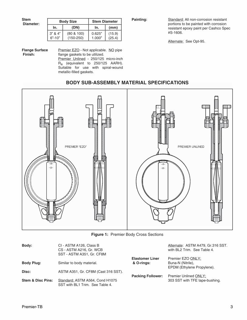
Body: CI - ASTM A126, Class B CS - ASTM A216, Gr. WCB SST - ASTM A351, Gr. CF8M
Body Plug: Similar to body material.
Disc: ASTM A351, Gr. CF8M (Cast 316 SST).
Stem & Disc Pins: Standard: ASTM A564, Cond H1075 SST with BL1 Trim. See Table 4.
Figure 1: Premier Body Cross Sections
Alternate: ASTM A479, Gr.316 SST. with BL2 Trim. See Table 4.
Elastomer Liner Premier EZO ONLY; & O-rings: Buna-N (Nitrile), EPDM (Ethylene Propylene).
Packing Follower: Premier Unlined ONLY; 303 SST with TFE tape-bushing.
4 Premier-TB
Packing: Premier Unlined ONLY; Braided TFE, split-ring.
Packing Flange: Premier EZO; 304 SST.
Premier Unlined; Body Sizes 3” & 4” (DN80 & 100), 304 SST. Body Sizes 6” - 10” (DN150 - 250), Ductile Iron.
Upper Sleeve: Premier Unlined ONLY; 316 SST.
Bearings: Premier EZO; TFE-lined fiberglass.
Premier Unlined; Stem - TFE-lined 316 SST, Thrust - TFE.
Cap Screws, 18-8 SST.Studs & Nuts:
Yoke: Body Sizes 3” & 4” (DN80 & 100), Carbon Steel structural tube. Body Sizes 6” - 10” (DN150 - 250), Ductile Iron.
ACTUATOR TECHNICAL SPECIFICATIONS
Basic Design: 0-90° Rotary. Spring-diaphragm. Rolling diaphragm with multiple springs. Enclosed linkage. Field-reversible for “direct” or “reverse” action (see Fig. 3). Standard with manual handwheel operator.
ActionModel
No.Body Size
Bench Setting Range
psig (Barg)
Direct; ATC-FO(Increase in air “LOAD” rotates valve stem CW, closing valve)
48D-013” & 4” *
(DN80 & 100)5 - 13 (0.34 - 0.90)
148D-016” *
(DN150)5 - 13 (0.34 - 0.90)
148D-03
8” (DN200) *
7.5 - 19.5 (0.52 - 1.34)Premier Unlined ONLY
10” (DN250)
148D-02Premier EZO
ONLY10” (DN250)
10 - 26 (0.69 - 1.79)
Reverse; ATO-FC
(Increase in air “LOAD” rotates
stem CCW, opening valve)
48R-013” & 4” *
(DN80 & 100)5 - 15 (0.34 - 1.03)
148R-016” *
(DN150)5 - 13 (0.34 - 0.90)
148R-03
8” (DN200) *
7.5 - 19.5 (0.52 - 1.34)Premier Unlined ONLY
10” (DN250)
148R-02Premier EZO
ONLY10” (DN250)
10 - 26 (0.69 - 1.79)
* Both Premier EZO & Premier Unlined
ATC-FO = Air-to-Close, Fail OpenATO-FC = Air-to-Open, Fail Close
NOTE: No actuator bench setting range selection required; i.e., one actuator for each body size.
Size, Stroke & Volume:
Basic Model
No.
Nominal Diaphragm
Area
Lever Arm Length
Nominal Stroke *
Volumes
Clearance Volumetric
in2 (cm2) in (mm) in (mm) in3 (cm3) in3 (cm3)
48D48R
48 (310) 1.375 (34.9) 1.94 (49.3) 27 (440) 87 (1425)
148D148R
148 (955) 1.875 (47.6) 2.65 (67.3) 90 (1475) 372 (6095)
* To generate 90° rotation
Maximum 48 D/R = 20 psig (1.38 Barg). Operating 148 D/R = 36 psig (2.48 Barg). Supply Pressure:
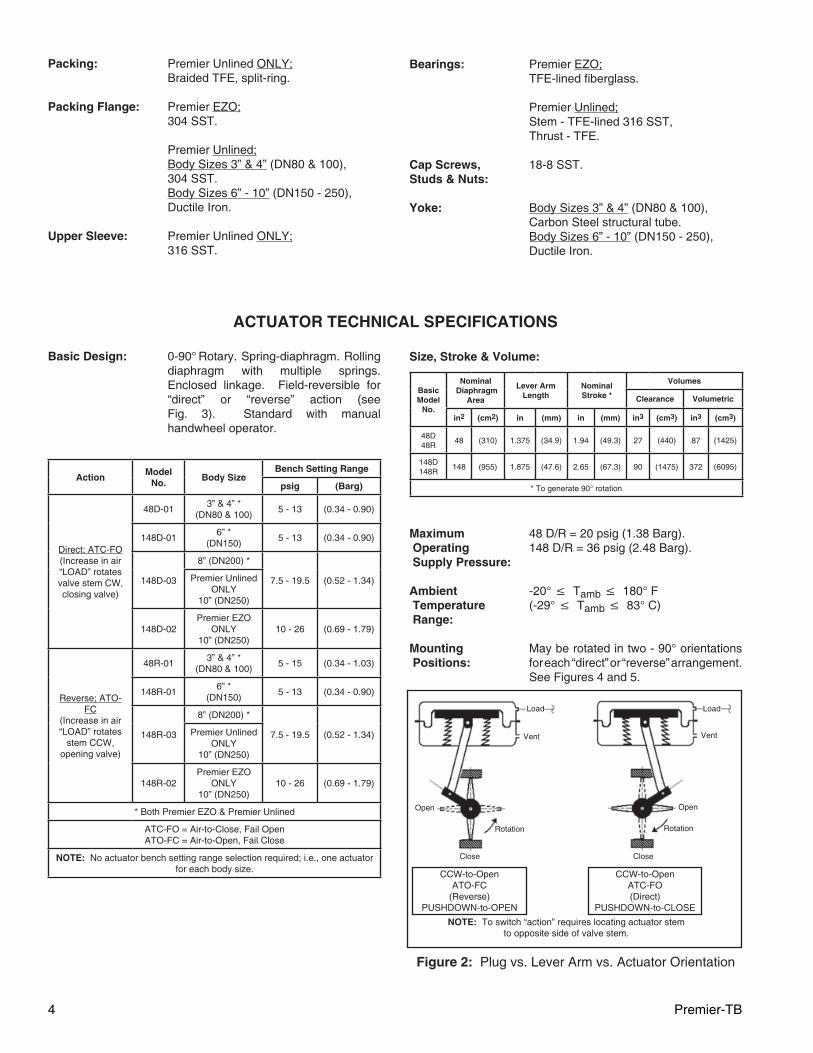
Ambient -20° ≤ Tamb ≤ 180° F Temperature (-29° ≤ Tamb ≤ 83° C) Range: Mounting May be rotated in two - 90° orientations Positions: for each “direct” or “reverse” arrangement. See Figures 4 and 5.
Figure 2: Plug vs. Lever Arm vs. Actuator Orientation
Load Load
Vent Vent
Open Open
RotationRotation
Close Close
CCW-to-OpenATC-FO(Direct)
PUSHDOWN-to-CLOSE
CCW-to-OpenATO-FC
(Reverse)PUSHDOWN-to-OPEN
NOTE: To switch “action” requires locating actuator stem to opposite side of valve stem.
Premier-TB 5
Travel Stop Standard - Limits travel to 0° - 90° Screw: rotational travel.
Air Connection: 1/4” female NPT.
Stroking Time: Reference STKSP-TB for stroke times with various accessories.
ACTUATOR SUB-ASSEMBLY MATERIAL SPECIFICATIONS
Casings & Cast aluminum; ASTM B108, Diaphragm UNS A13560. Plate:
Springs: Epoxy coated steel.
Diaphragm: Rolling-type; Buna-N with polyester fabric.
Arm Housing: Cast iron.
Top-Case Plug: Naval brass.
Flange Bolting: 18-8 SST.
Turnbuckle Plated steel and SST. Assembly:
Travel Stop Plated Steel. Screw & Jamnut:
Lever Arms: SST with SST bolt and nut.
Cam/Spacer: SST.
Nameplate: SST.
Option-3: Handwheel: Cast aluminum. Handwheel Stem: 316 SST. Handwheel Gland: Naval brass. Locking Lever: Plated malleable iron. Threadseal: 18-8 SST with Buna-N insert.
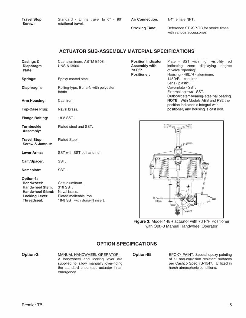
Position Indicator Plate - SST with high visibility red Assembly with indicating zone displaying degree 73 P/P of valve “opening”. Positioner: Housing - 48D/R - aluminum; 148D/R, - cast iron. Lens - plastic. Coverplate - SST. External screws - SST. Outboard stem bearing - steel ball bearing. NOTE: With Models ABB and PS2 the position indicator is integral with positioner, and housing is cast iron.
Figure 3: Model 148R actuator with 73 P/P Positioner with Opt.-3 Manual Handwheel Operator
OPTION SPECIFICATIONS
Option-3: MANUAL HANDWHEEL OPERATOR. A handwheel and locking lever are supplied to allow manually over-riding the standard pneumatic actuator in an emergency.
Option-95: EPOXY PAINT. Special epoxy painting of all non-corrosion resistant surfaces per Cashco Spec #S-1547. Utilized in harsh atmospheric conditions.
6 Premier-TB
Premier-TB 7
MOUNTED ACCESSORY SPECIFICATIONS
Positioners:
Air Tubing:
Airset:
Solenoid Valve:
Transducers
OtherAccessories:
Limit Switches:
Model PS2-1 is general purpose.Model PS2-2 is Intrinsically safe, ATEX Ex ia IIC T6/T4, FM CLS 1 DIV 1,CSA CLS 1 DIV 1, SIL 2Model PS2-3 EX d IIC T6/T4, SIL 2
Instrument air tubing SST with SST fittings.
Model 5200P instrument air supply reg u la tor. Use with positioners. Brack et mount ed to actuator casing. Sup plied with gauge. See technical bul le tin 5200P-TB.
Standard Brass: Available in stan dard weather-proof model. Brass body, 1/4" fe male NPT con nec tions. Nip ple mounted to ac tu a tor cas ing. 120 VAC, 60 Hz pow er sup ply, CSA Approved Class 3221-01, NEMA 2,3,3S,4,4X. 8" HF utilizes a direct mount NAMUR mount style.
X-Proof or SST construction: Consult Factory.
Standard installation vents actuator and drives valve to fail-safe position upon loss of electrical power.
Consult factory for 230/1/50, or 120 VDC power supplies, or in trin si cal ly safe (IS) service.
FM, CSA approved NEMA 4X Cl 1, Div 1 and Cl 1, Div 2
764 P/PD pressure controller.Lockup valve.Position transmitter.
Model D20 and D3 positioners, switches are available, unit is enclosed in the positioner housing.
Limit switch options not available on Explosion proof rated positioners.
General. Mounted to arm housing. All feedback linkage is enclosed and not exposed directly to elements.
P/P Pneumatic. Model 73. Ad just able zero only. Analog signal only. Includes gauge port, with gauge. Not Available on 8" HF.
General: PMV Positioners. Alu mi num housing with cor ro sion resistant powder coated epoxy. Pneumatic output load as required by actuator bench range. Field re vers ible action. Mounting di-mensions per IEC 60534-6-2 Standard.
P/P Pneumatic. Model P5 features SST cam with a simple cam locking device, tapped exhaust port for venting media, external zero ad just ment. Input signal 3-15 psig, Includes gauge ports, no gauges. Analog only.
I/P Electro-Pneumatic. Model D20 Digital and Hart compatible. Features single button self-calibration. input sig-nal 4-20mA. Optional gauge block with gauges for Models D20 D and D20 I.Model D20 D is general purpose.Model D20 I is Intrinsically safe, ATEX Ex ia IIC T4, FM CLS 1 DIV 1, FM Non-incendive CLS 1 DIV 2.Model D20 E is ATEX EEX d IIB+H2, T6 FM Approved. Gauge block is built in, no gauges. Not available with limit switch option.
I/P Electro-Pneumatic. Model D3 Digi-tal, Hart, Profibus, and Fieldbus compat-ible. Input signal 4-20mA. Features large graphic display. Optional gauge block for Models D3 X and D3 I, no gauges.Model D3 X is general purpose. Model D3 I is Intrinsically safe, ATEXEEX ia IIC T4.Model D3 E is ATEX EEX d IIB+H2, T6CSA CLS 1 DIV 1FM CLS 1 DIV 1Gauge block is built in, no gauges. Not available with limit switch option.
Model PS2 is Hart, Fieldbus and Profibus compatible. Input signal 4-20mA. Fea-tures a Makrolon housing, (Aluminum for Explosion Proof.) Mounting dimensions per IEC 60534-6-2 Standard.
8 Premier-TB
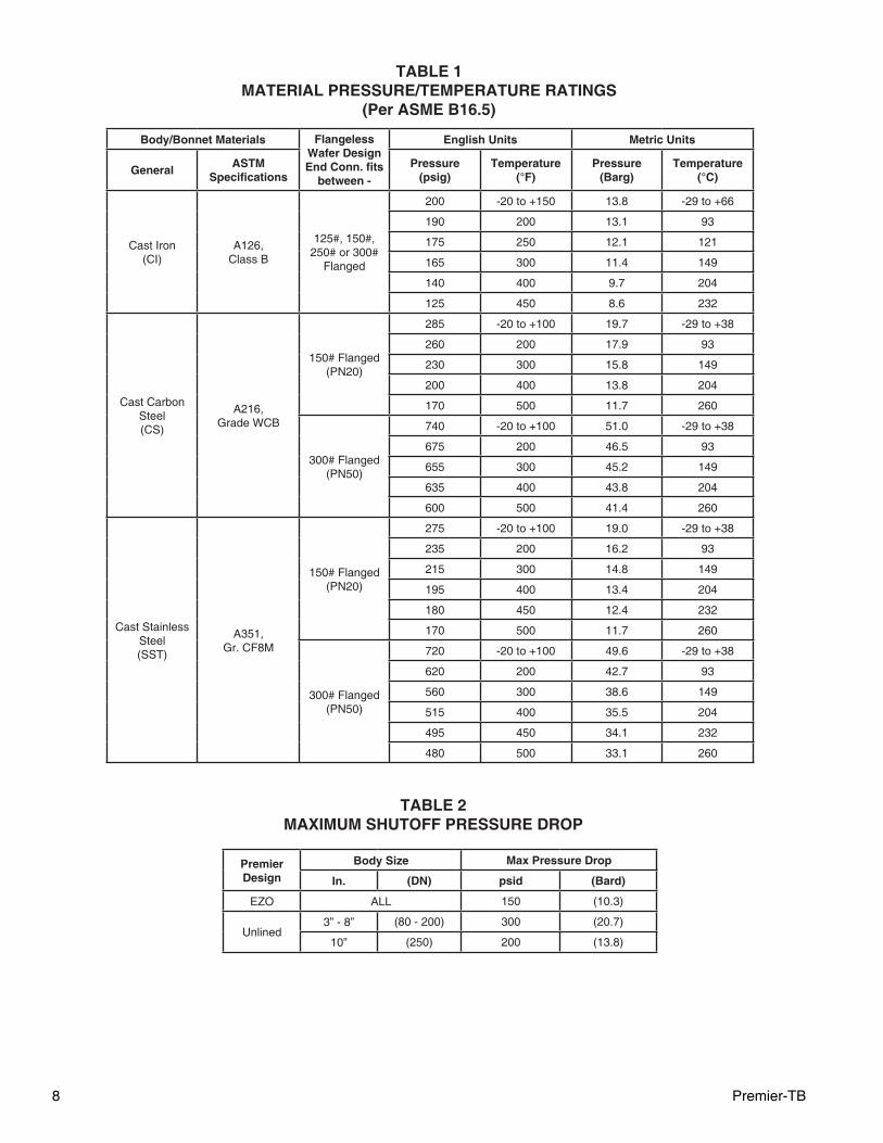
TABLE 1MATERIAL PRESSURE/TEMPERATURE RATINGS
(Per ASME B16.5)
Body/Bonnet Materials Flangeless Wafer Design End Conn. fits
between -
English Units Metric Units
GeneralASTM
Specifi cationsPressure
(psig)Temperature
(°F)Pressure
(Barg)Temperature
(°C)
Cast Iron(CI)
A126, Class B
125#, 150#,250# or 300#
Flanged
200 -20 to +150 13.8 -29 to +66
190 200 13.1 93
175 250 12.1 121
165 300 11.4 149
140 400 9.7 204
125 450 8.6 232
Cast Carbon Steel(CS)
A216,Grade WCB
150# Flanged(PN20)
285 -20 to +100 19.7 -29 to +38
260 200 17.9 93
230 300 15.8 149
200 400 13.8 204
170 500 11.7 260
300# Flanged(PN50)
740 -20 to +100 51.0 -29 to +38
675 200 46.5 93
655 300 45.2 149
635 400 43.8 204
600 500 41.4 260
Cast Stainless Steel(SST)
A351,Gr. CF8M
150# Flanged(PN20)
275 -20 to +100 19.0 -29 to +38
235 200 16.2 93
215 300 14.8 149
195 400 13.4 204
180 450 12.4 232
170 500 11.7 260
300# Flanged(PN50)
720 -20 to +100 49.6 -29 to +38
620 200 42.7 93
560 300 38.6 149
515 400 35.5 204
495 450 34.1 232
480 500 33.1 260
TABLE 2MAXIMUM SHUTOFF PRESSURE DROP
Premier Design
Body Size Max Pressure Drop
In. (DN) psid (Bard)
EZO ALL 150 (10.3)
Unlined3” - 8” (80 - 200) 300 (20.7)
10” (250) 200 (13.8)
Premier-TB 9
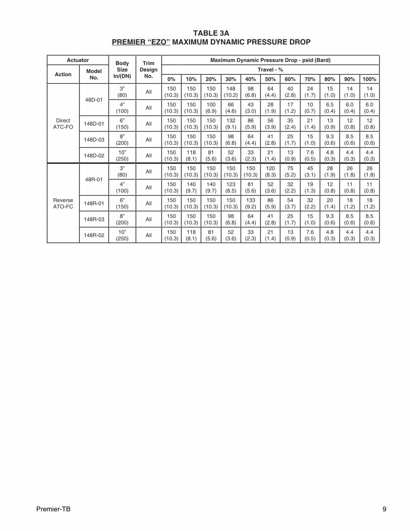
TABLE 3APREMIER “EZO” MAXIMUM DYNAMIC PRESSURE DROP
Actuator Body Size
In/(DN)
Trim Design
No.
Maximum Dynamic Pressure Drop - psid (Bard)
ActionModel
No.Travel - %
0% 10% 20% 30% 40% 50% 60% 70% 80% 90% 100%
DirectATC-FO
48D-01
3”(80)
All150
(10.3)150
(10.3)150
(10.3)148
(10.2)98
(6.8)64
(4.4)40
(2.8)24
(1.7)15
(1.0)14
(1.0)14
(1.0)
4”(100)
All150
(10.3)150
(10.3)100(6.9)
66(4.6)
43(3.0)
28(1.9)
17(1.2)
10(0.7)
6.5(0.4)
6.0(0.4)
6.0(0.4)
148D-016”
(150)All
150(10.3)
150(10.3)
150(10.3)
132(9.1)
86(5.9)
56(3.9)
35(2.4)
21(1.4)
13(0.9)
12(0.8)
12(0.8)
148D-038”
(200)All
150(10.3)
150(10.3)
150(10.3)
98(6.8)
64(4.4)
41(2.8)
25(1.7)
15(1.0)
9.3(0.6)
8.5(0.6)
8.5(0.6)
148D-0210”
(250)All
150(10.3)
118(8.1)
81(5.6)
52(3.6)
33(2.3)
21(1.4)
13(0.9)
7.6(0.5)
4.8(0.3)
4.4(0.3)
4.4(0.3)
Reverse ATO-FC
48R-01
3”(80)
All150
(10.3)150
(10.3)150
(10.3)150
(10.3)150
(10.3)120(8.3)
75(5.2)
45(3.1)
28(1.9)
26(1.8)
26(1.8)
4”(100)
All150
(10.3)140(9.7)
140(9.7)
123(8.5)
81(5.6)
52(3.6)
32(2.2)
19(1.3)
12(0.8)
11(0.8)
11(0.8)
148R-016”
(150)All
150(10.3)
150(10.3)
150(10.3)
150(10.3)
133(9.2)
86(5.9)
54(3.7)
32(2.2)
20(1.4)
18(1.2)
18(1.2)
148R-038”
(200)All
150(10.3)
150(10.3)
150(10.3)
98(6.8)
64(4.4)
41(2.8)
25(1.7)
15(1.0)
9.3(0.6)
8.5(0.6)
8.5(0.6)
148R-0210”
(250)All
150(10.3)
118(8.1)
81(5.6)
52(3.6)
33(2.3)
21(1.4)
13(0.9)
7.6(0.5)
4.8(0.3)
4.4(0.3)
4.4(0.3)
10 Premier-TB
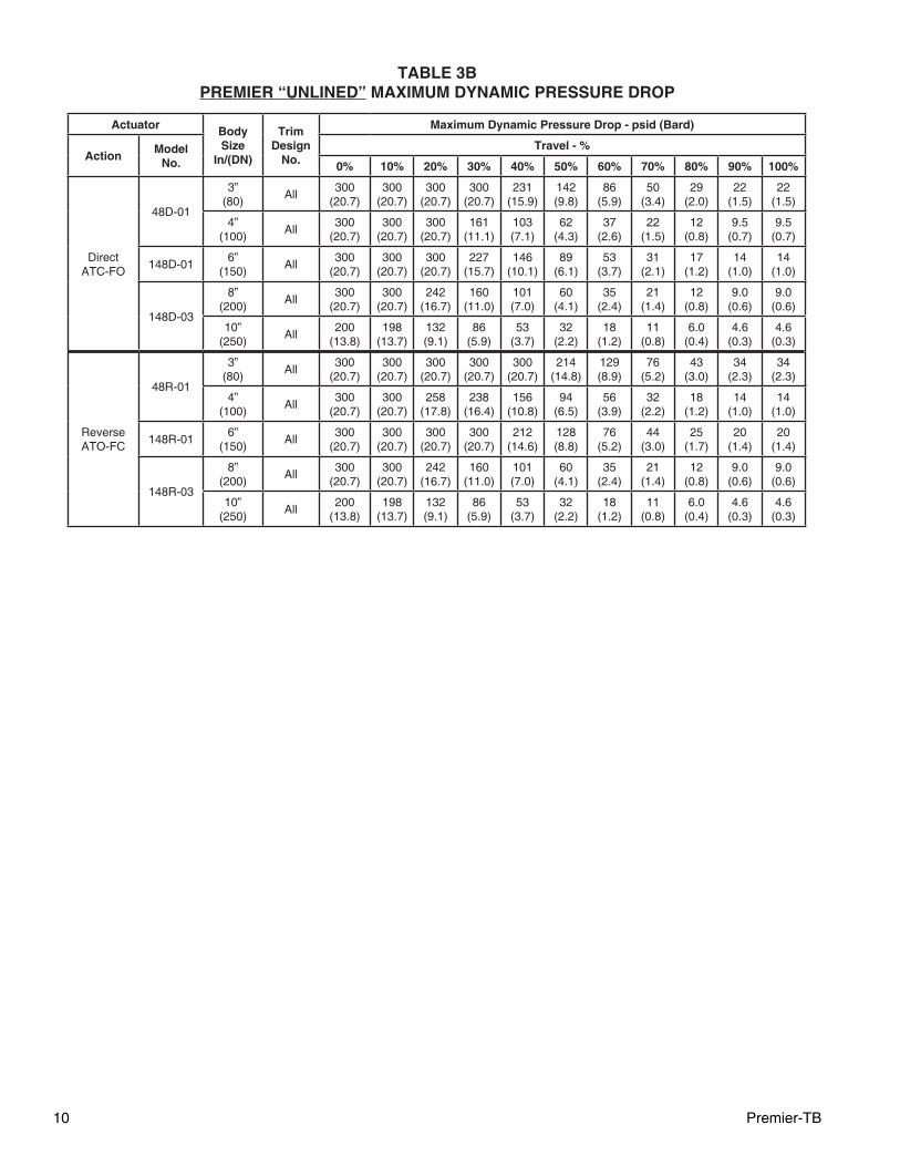
TABLE 3BPREMIER “UNLINED” MAXIMUM DYNAMIC PRESSURE DROP
Actuator Body Size
In/(DN)
Trim Design
No.
Maximum Dynamic Pressure Drop - psid (Bard)
ActionModel
No.Travel - %
0% 10% 20% 30% 40% 50% 60% 70% 80% 90% 100%
DirectATC-FO
48D-01
3”(80)
All300
(20.7)300
(20.7)300
(20.7)300
(20.7)231
(15.9)142(9.8)
86(5.9)
50(3.4)
29(2.0)
22(1.5)
22(1.5)
4”(100)
All300
(20.7)300
(20.7)300
(20.7)161
(11.1)103(7.1)
62(4.3)
37(2.6)
22(1.5)
12(0.8)
9.5(0.7)
9.5(0.7)
148D-016”
(150)All
300(20.7)
300(20.7)
300(20.7)
227(15.7)
146(10.1)
89(6.1)
53(3.7)
31(2.1)
17(1.2)
14(1.0)
14(1.0)
148D-03
8”(200)
All300
(20.7)300
(20.7)242
(16.7)160
(11.0)101(7.0)
60(4.1)
35(2.4)
21(1.4)
12(0.8)
9.0(0.6)
9.0(0.6)
10”(250)
All200
(13.8)198
(13.7)132(9.1)
86(5.9)
53(3.7)
32(2.2)
18(1.2)
11(0.8)
6.0(0.4)
4.6(0.3)
4.6(0.3)
Reverse ATO-FC
48R-01
3”(80)
All300
(20.7)300
(20.7)300
(20.7)300
(20.7)300
(20.7)214
(14.8)129(8.9)
76(5.2)
43(3.0)
34(2.3)
34(2.3)
4”(100)
All300
(20.7)300
(20.7)258
(17.8)238
(16.4)156
(10.8)94
(6.5)56
(3.9)32
(2.2)18
(1.2)14
(1.0)14
(1.0)
148R-016”
(150)All
300(20.7)
300(20.7)
300(20.7)
300(20.7)
212(14.6)
128(8.8)
76(5.2)
44(3.0)
25(1.7)
20(1.4)
20(1.4)
148R-03
8”(200)
All300
(20.7)300
(20.7)242
(16.7)160
(11.0)101(7.0)
60(4.1)
35(2.4)
21(1.4)
12(0.8)
9.0(0.6)
9.0(0.6)
10”(250)
All200
(13.8)198
(13.7)132(9.1)
86(5.9)
53(3.7)
32(2.2)
18(1.2)
11(0.8)
6.0(0.4)
4.6(0.3)
4.6(0.3)
Premier-TB 11
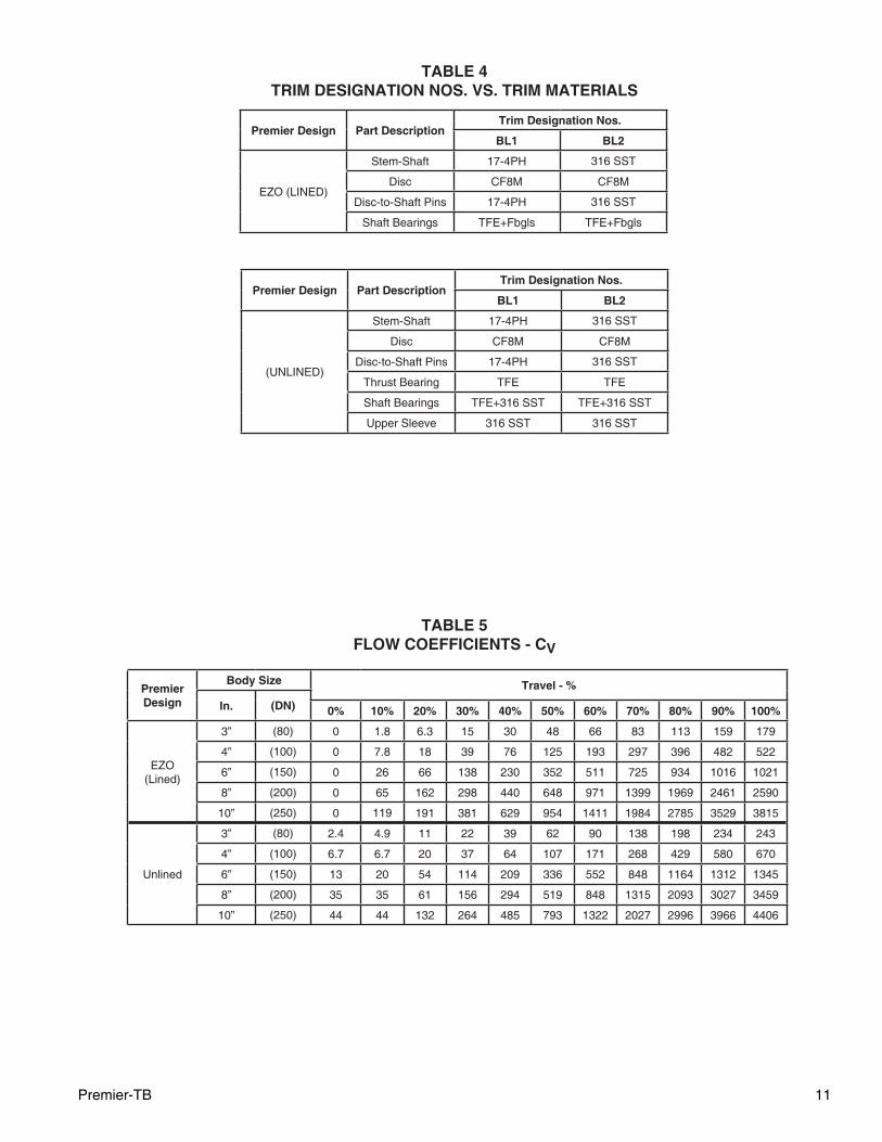
TABLE 4TRIM DESIGNATION NOS. VS. TRIM MATERIALS
Premier Design Part DescriptionTrim Designation Nos.
BL1 BL2
EZO (LINED)
Stem-Shaft 17-4PH 316 SST
Disc CF8M CF8M
Disc-to-Shaft Pins 17-4PH 316 SST
Shaft Bearings TFE+Fbgls TFE+Fbgls
Premier Design Part DescriptionTrim Designation Nos.
BL1 BL2
(UNLINED)
Stem-Shaft 17-4PH 316 SST
Disc CF8M CF8M
Disc-to-Shaft Pins 17-4PH 316 SST
Thrust Bearing TFE TFE
Shaft Bearings TFE+316 SST TFE+316 SST
Upper Sleeve 316 SST 316 SST
TABLE 5FLOW COEFFICIENTS - CV
Premier Design
Body Size Travel - %
In. (DN) 0% 10% 20% 30% 40% 50% 60% 70% 80% 90% 100%
EZO (Lined)
3” (80) 0 1.8 6.3 15 30 48 66 83 113 159 179
4” (100) 0 7.8 18 39 76 125 193 297 396 482 522
6” (150) 0 26 66 138 230 352 511 725 934 1016 1021
8” (200) 0 65 162 298 440 648 971 1399 1969 2461 2590
10” (250) 0 119 191 381 629 954 1411 1984 2785 3529 3815
Unlined
3” (80) 2.4 4.9 11 22 39 62 90 138 198 234 243
4” (100) 6.7 6.7 20 37 64 107 171 268 429 580 670
6” (150) 13 20 54 114 209 336 552 848 1164 1312 1345
8” (200) 35 35 61 156 294 519 848 1315 2093 3027 3459
10” (250) 44 44 132 264 485 793 1322 2027 2996 3966 4406
12 Premier-TB
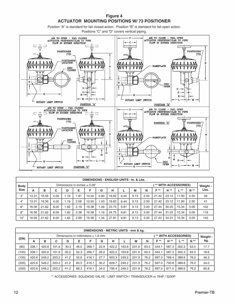
Figure 4ACTUATOR MOUNTING POSITIONS W/ 73 POSITIONER
Position “A” is standard for fail closed action. Position “B” is standard for fail open action. Positions “C” and “D” covers vertical piping.
DIMENSIONS - ENGLISH UNITS - In. & Lbs. .
Body Size
Dimensions in inches ± 0.06” ( ** WITH ACCESSORIES) Weight - Lbs.A B C D E F G H L M N F ** H ** L ** N **
3” 13.31 16.56 4.00 1.19 1.81 10.50 0.90 16.62 6.44 9.13 2.50 21.42 23.12 11.90 2.50 39
4” 13.31 16.56 4.00 1.19 2.06 10.50 1.03 16.62 6.44 9.13 2.50 21.42 23.12 11.90 2.50 41
6” 16.56 21.62 8.00 1.62 2.19 16.38 1.09 23.75 9.81 9.13 3.00 27.44 30.25 15.34 3.00 102
8” 16.56 21.62 8.00 1.62 2.38 16.38 1.19 24.75 9.81 9.13 3.00 27.44 31.25 15.34 3.00 119
10” 16.56 21.62 8.00 1.62 2.69 16.38 1.34 27.81 9.81 9.13 3.00 27.44 34.31 15.34 3.00 145
DIMENSIONS - METRIC UNITS - mm & kg. .
(DN) Dimensions in millimeters ± 1.6 mm ( ** WITH ACCESSORIES) Weight -
kg.A B C D E F G H L M N F ** H ** L ** N **
(80) 338.1 420.6 101.6 30.2 46.0 266.7 22.9 422.2 163.6 231.9 63.5 544.1 587.3 302.3 63.5 17.7
(100) 338.1 420.6 101.6 30.2 52.3 266.7 26.2 422.2 163.6 231.9 63.5 544.1 587.3 302.3 63.5 18.6
(150) 420.6 549.2 203.2 41.2 55.6 416.1 27.7 603.3 249.2 231.9 76.2 697.0 768.4 389.6 76.2 46.3
(200) 420.6 549.2 203.2 41.2 60.5 416.1 30.2 628.7 249.2 231.9 76.2 697.0 793.8 389.6 76.2 54.0
(250) 420.6 549.2 203.2 41.2 68.3 416.1 34.0 706.4 249.2 231.9 76.2 697.0 871.5 389.6 76.2 65.8
** ACCESSORIES: SOLENOID VALVE / LIMIT SWITCH / TRANSDUCER or 764P / 5200P
Premier-TB 13
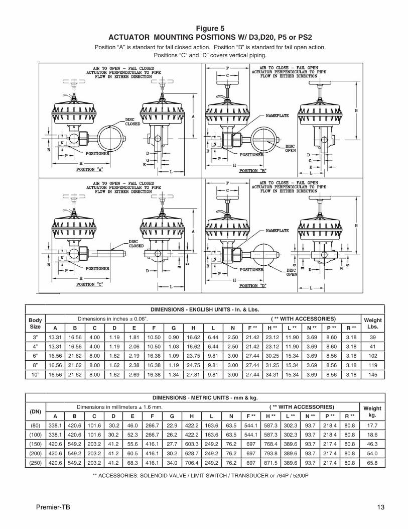
Figure 5ACTUATOR MOUNTING POSITIONS W/ D3,D20, P5 or PS2
Position “A” is standard for fail closed action. Position “B” is standard for fail open action. Positions “C” and “D” covers vertical piping.
DIMENSIONS - ENGLISH UNITS - In. & Lbs.
Body Size
Dimensions in inches ± 0.06”. ( ** WITH ACCESSORIES) Weight Lbs.A B C D E F G H L N F ** H ** L ** N ** P ** R **
3” 13.31 16.56 4.00 1.19 1.81 10.50 0.90 16.62 6.44 2.50 21.42 23.12 11.90 3.69 8.60 3.18 39
4” 13.31 16.56 4.00 1.19 2.06 10.50 1.03 16.62 6.44 2.50 21.42 23.12 11.90 3.69 8.60 3.18 41
6” 16.56 21.62 8.00 1.62 2.19 16.38 1.09 23.75 9.81 3.00 27.44 30.25 15.34 3.69 8.56 3.18 102
8” 16.56 21.62 8.00 1.62 2.38 16.38 1.19 24.75 9.81 3.00 27.44 31.25 15.34 3.69 8.56 3.18 119
10” 16.56 21.62 8.00 1.62 2.69 16.38 1.34 27.81 9.81 3.00 27.44 34.31 15.34 3.69 8.56 3.18 145
DIMENSIONS - METRIC UNITS - mm & kg.
(DN) Dimensions in millimeters ± 1.6 mm. ( ** WITH ACCESSORIES) Weight
kg.A B C D E F G H L N F ** H ** L ** N ** P ** R **
(80) 338.1 420.6 101.6 30.2 46.0 266.7 22.9 422.2 163.6 63.5 544.1 587.3 302.3 93.7 218.4 80.8 17.7
(100) 338.1 420.6 101.6 30.2 52.3 266.7 26.2 422.2 163.6 63.5 544.1 587.3 302.3 93.7 218.4 80.8 18.6
(150) 420.6 549.2 203.2 41.2 55.6 416.1 27.7 603.3 249.2 76.2 697 768.4 389.6 93.7 217.4 80.8 46.3
(200) 420.6 549.2 203.2 41.2 60.5 416.1 30.2 628.7 249.2 76.2 697 793.8 389.6 93.7 217.4 80.8 54.0
(250) 420.6 549.2 203.2 41.2 68.3 416.1 34.0 706.4 249.2 76.2 697 871.5 389.6 93.7 217.4 80.8 65.8
** ACCESSORIES: SOLENOID VALVE / LIMIT SWITCH / TRANSDUCER or 764P / 5200P

14 Premier-TB
NOTES
The contents of this publication are presented for informational purposes only, and while every effort has been made to ensure their accuracy, they are not to be con-strued as warranties or guarantees, express or implied, regarding the products or services described herein or their use or applicability. We reserve the right to modify or improve the designs or specifi cations of such product at any time without notice.Cashco, Inc. does not assume responsibility for the selection, use or maintenance of any product. Responsibility for proper selection, use and maintenance of any Cashco, Inc. product remains solely with the purchaser.
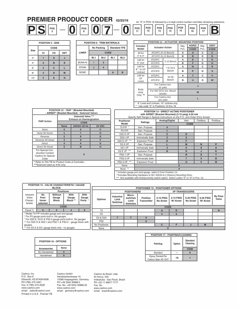
POSITION 3 - SIZE
SizeCODE
CI CS SST
3" 1 A J
4" 2 B K
6" 3 C L
8" 4 D M
10" 5 E N
POSITION 6 - TRIM MATERIALS
LINER
No Packing Standard TFE
CODE
BL1 BL2 BL1 BL2
BUNA-N 1 3
EPDM 2 4
NONE A B
P POS147 BS POS
3POS
6POS16
POS15
POS17
POS11
POSITION 17 - PAINTING/CLEANING
Painting OptionStandard Cleaning
CODE
Standard — 0
Epoxy Painted Per Cashco Spec #S-1547
-95 1
000 POS13
POS12
POSITIONER 15 - POSITIONER OPTIONS
Options
POSITIONERS I/P TRANSDUCERS
By Pass Valve
InductiveLimit
Switches
Micro-switches
LimitSwitches
PositionTransmitter
3-15 PSIGNo Airset
3-15 PSIGW/ Airset
6-30 PSIGNo Airset
6-30 PSIGW/ Airset
CODE73 A D N
P5 4 5
D3 & D20 7 T 9
PS2 8No Positioner C F J M
None 0
PREMIER PRODUCT CODER 02/25/16
Cashco, Inc.P.O. Box 6 Ellsworth, KS 67439-0006PH (785) 472-4461Fax. # (785) 472-3539www.cashco.comemail: [email protected] in U.S.A. Premier-TB
Cashco do Brasil, Ltda.Al.Venus, 340Indaiatuba - Sao Paulo, BrazilPH +55 11 99677 7177Fax. No. www.cashco.comemail: [email protected]
POSITION 12 - 764P * (Bracket Mounted)- AIRSET* (Bracket Mounted) - Solenoid Valves
764P Action
Solenoid Valve ***Exhaust on Deenergization
CODENone 120VAC 60 Hz 24 VDC
None 0 6 CNone W/ Airset 1 7 D
Reverse 2 8 EReverse W/ Airset 3 9 F
Direct 4 A GDirect W/ Airset 5 B H
For Special Con-struction Contact
Cashco for Special Code
X
* Refer to 764-TB for Product Code of Controller..***Solenoid rated as 4/4X only.
POSITION 11 - ACTUATOR MOUNTING POSITIONActuator
Model Actuator Action Mtg.Pos.
HORIZ Mtg.Pos.
VERTCODE CODE
48 for3” & 4”
ATO/FC (5-15 Bench) A A C CATC/FO (5-13 Bench) B B D D
148 for6” size
ATO/FC5-13 Bench
A E C GATC/FO B F D H
148 for8” * & 10”Unlined
ATO/FC 7.5-19.5 Bench
A N C R
ATC/FO B P D S
148 for10”
Lined
ATO/FC 10-26 Bench
A T C V
ATC/FO B U D W
Body Assy
Only **
For Cashco Act.w/ yoke J
For ISO 5211 Act. Mountw/yoke M
For Cashco Act.w/o yoke L
* 8” Lined and Unlined. 10” Unlined only.** Use code "0" in Positions 12 thru 16
An “X” in POS 12 followed by a 5-digit control num ber over rides remaining selections.
Cashco GmbHHandwerkerstrasse 1515366 Hoppegarten, GermanyPH +49 3342 30968 0Fax. No. +49 3342 30968 29www.cashco.comemail: [email protected]
POSITION 13 - DIRECT ACTING POSITIONERwith AIRSET (Bracket Mounted) (3-15 psig) 4-20 mA
Specify Split Range in Special Instructions on the P.O. and Order Entry Screen
PositionerModel
RatingsAnalog/Digital Hart Fieldbus Profi bus
CODE73 P/P * Gen. Purpose 4P5 P/P Gen. Purpose 1
D20 D I/P Gen. Purpose C DD20 I I/P Intrinsically Safe 2 5
D20 E I/P *** Explosion Proof E FD3 X I/P Gen. Purpose L M N PD3 I I/P Intrinsically Safe 3 6 8 A
D3 E I/P *** Explosion Proof G H J K
PS2-1 I/P Gen. Purpose R S T
PS2-2 I/P Intrinsically Safe 7 9 B
PS2-3 I/P *** Explosion Proof U V WNone 0
None ** #* Includes gauge port and gauge, select 6 from Position 14. **Includes Mounting Hardware to IEC 60534-6-2 (Namur) Mounting Dims.*** Not available with limit/proximity switch option. Select codes “9” or “8” in Pos. 15.
POSITION 16 - OPTIONS
Accessories None
No Handwheel 0Handwheel 9
POSITION 14 - VALVE CHARACTERISTIC / GAUGE BLOCK
InherentValve
Charac-teristic
PositionerNo
Posi-tioner
selected
WithoutGauge Block
WithGauge
Block **
WithGaugePorts *
CODE
Equal % 0 3 4 6
* Model 73 P/P includes gauge port and gauge.* For P5 gauge ports built in. No gauges.* For D20 E, D3 E & PS2-3 gauge ports built-in. No gauges** For D20 D & D20 I and PS2-1 & PS2-2 - gauge block with gauges.** For D3 X & D3 I gauge block only - no gauges.