ISAT ELEC INFRASTRUCTURE L3 2014-15.pdf
20
1 NATIONAL CERTIFICATE (VOCATIONAL) NQF LEVEL 3 INTEGRATED SUMMATIVE ASSESSMENT TASK PROGRAMME ISAT: ELECTRICAL INFRASTRUCTURE AND CONSTRUCTION 2014 - 2015 This document consists of 14 pages.
-
Upload
medley-chalez-wadada -
Category
Documents
-
view
12 -
download
1
Transcript of ISAT ELEC INFRASTRUCTURE L3 2014-15.pdf

1
NATIONAL CERTIFICATE (VOCATIONAL)
NQF LEVEL 3
INTEGRATED SUMMATIVE ASSESSMENT TASK
PROGRAMME ISAT:
ELECTRICAL INFRASTRUCTURE AND CONSTRUCTION
2014 - 2015
This document consists of 14 pages.
2
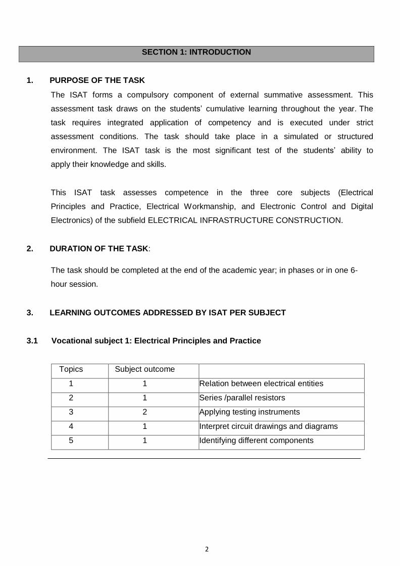
SECTION 1: INTRODUCTION
1. PURPOSE OF THE TASK
The ISAT forms a compulsory component of external summative assessment. This
assessment task draws on the students’ cumulative learning throughout the year. The
task requires integrated application of competency and is executed under strict
assessment conditions. The task should take place in a simulated or structured
environment. The ISAT task is the most significant test of the students’ ability to
apply their knowledge and skills.
This ISAT task assesses competence in the three core subjects (Electrical
Principles and Practice, Electrical Workmanship, and Electronic Control and Digital
Electronics) of the subfield ELECTRICAL INFRASTRUCTURE CONSTRUCTION.
2. DURATION OF THE TASK:
The task should be completed at the end of the academic year; in phases or in one 6-
hour session.
3. LEARNING OUTCOMES ADDRESSED BY ISAT PER SUBJECT
3.1 Vocational subject 1: Electrical Principles and Practice
Topics Subject outcome
1 1 Relation between electrical entities
2 1 Series /parallel resistors
3 2 Applying testing instruments
4 1 Interpret circuit drawings and diagrams
5 1 Identifying different components

3
3.2 Vocational subject 2: Electrical Workmanship
Topics Subject outcome
1 1&2 Apply safety procedures
2 1 Know treatment to injuries
3 1&2 Have knowledge regarding the use of hand
and power tools 4 1 Workshop procedures
3.3 Vocational subject 3: Electronic Control and Digital Electronics
Topics Subject outcome
1 1 & 2 & 3 & 4 Components and circuit drawings,
1 1 & 2 Soldering of circuit
3.4 Weighted value of topics:
TOPIC Weighted value
(A) Adherence to safety rules and procedures
(B) Selection, use and care for safety equipment, hand tools,
power tools, and electronic test equipment
(C) Identification and functioning of basic electronic and
electrical components
(D) Soldering techniques
(E) Workmanship (overall impression of completed task)
(F) Fundamentals of electricity with respect to DC circuits
25%
14%
14%
19%
10%
18%

4
4. COMPONENTS AND MATERIALS
MATERIALS DESCRIPTION VALUE QUANTITY
COMPONENTS AND
CONSUMABLES
1 Resistor (R1) Fixed carbon 470 Ω 1
2 Resistor (R2) Fixed carbon 2,2 kΩ 1
3 Resistor (R3) Fixed carbon 22 kΩ 1
4 Resistor (R4) Fixed carbon 100 kΩ 1
5 Diodes IN 4148 4
6 Capacitor 16 V (Radial) 0,1 µF 1
7 Capacitor 16 V (Radial) 1 µF 1
8 Transistor BC 108 1
9 Pre-set potentiometer Horizontal 1 MΩ 1
10 Timer IC 555 1`
11 Counter IC 4017 1
12 IC socket holder 16-pin DIL 1
13 IC Socket holders 8-pin DIL 1
14 2-pole, single throw Miniature switch Low voltage 1
15 Miniature lamp Or White LED
Screw type (ES) 6 Volt-60mA 1 1
16 Miniature Lamp Holder Screw type (ES)
17 Battery Clip PP3 9 Volt 1
18 Battery PM3 9 Volt 1
19 Veroboard 25 rows × 40 holes 70 mm × 50 mm
1
20 LED Holders Panel mount 2
21 Wire PVC Stranded Red and Black 0,5 mm2 100 mm
22 Wire PVC Solid Any colour 0,5 mm2 100 mm
23 Mirror Tape DS tape
24 Enclosure Box No. ABS 10 Black Obtainable at Communica
113 mm × 60 mm × 36 mm
1

5
TOOLS DESCRIPTION VALUE QUANTITY
1 Multi-meter Volt, Amp, etc. Range unit to Milli- ampere
1
2 Soldering iron 1,5 mm tip 1
3 Long nose pliers 1
4 Side cutters 1
5 Solder sucker 1
6 Drill bits 1
7 Terminal screwdriver 1
8 Power drill 1
Please note that the list contains the key/core materials needed. Lecturers must ensure that
students have all other materials, components and tools needed for the task.
5. ASSESSMENT
5.1 The following competencies will be assessed:
o Regulations regarding engineering practices
o Adherence to safety rules and procedures
o Selection, use and care for safety equipment, hand tools, power tools, and Electronic
test equipment
o Drawing, reading and interpreting of electronic and electrical circuit diagrams
o Construct basic electronic/electrical circuits
o Soldering techniques
o Good house-keeping practice
o Identification and funct ion ing of basic electronic and elect r ical components
o Fundamentals of electricity with respect to DC and AC circuits
o Application (ability to read, interpret and apply)
o Workmanship (overall impression of completed task)

6
5.2 Assessment tools to be used:
See RECORDING SHEET AND RUBRICS in Section 3.

7
SECTION 2: INSTRUCTIONS TO LECTURERS
1. 2. 3. 4. 5. 6. 7.
Ensure that the student understands the evaluation criteria.
Ensure that the student understands the competence descriptors of the assessment rubrics (attached).
The ISAT as a whole assesses the various skills attained in the three vocational subjects. Each lecturer is to ensure that during the year, students have sufficient practice to master the skills and knowledge required to complete the ISAT.
Assessors must assess the project in stages as indicated in INSTRUCTIONS TO CANDIDATES to ensure that valid and authentic assessment that measures the skills, knowledge, attitude and values (SKAV) required by the task, takes place.
The ISAT forms part of the learner’s promotional mark and therefore must be conducted under examination conditions in a simulated and structured environment. PERSONNEL REQUIRED: It is recommended that a ratio of 1 assessor to 15 candidates be used per session. A session will be 6 hours. It is essential that the entire project is completed in this time period. Assessors must be subject specialists.
It is further recommended that the college or campus ensures the presence of an internal moderator. Assessments must be moderated according to the internal moderation policy of the Further Education and Training (FET) College. The moderator’s involvement starts from the planning of the assessment stage and follows with continuous collaboration and support to the assessors. Internal moderation creates common understanding of Assessment Standards and maintains these across vocational programmes.

8
SECTION 3: ASSESSMENT TOOLS
TABLE 1: ISAT Assessment Recording Sheet (To be included in students POE)
NOTE: Provide all students with a copy of the CRITERIA CHECKLIST prior to engaging in the task.
Criteria Outstanding
(4) Highly
Competent (3)
Competent
(2)
Not achieved
(0 - 1)
(A) Safety, Selection and Use of hand and power tools 1. Selection of power tools 2. Use of power tools 3. Housekeeping 4. Selection of hand tools 5. Use of hand tools
Subtotal A (20) (B) Identification of components and materials 1. Identification of components as per circuit diagram
layout
2. Identification of materials as per circuit diagram layout
Subtotal B (8) (C) Arranging components on planning sheet 1. As per circuit diagram 2. Planning 3. Short circuits 4. Component polarity
Subtotal C (16) (D) Soldering and Layout of components 1. Arrangement of components on Veroboard 2. Cutting of tracks on Veroboard 3. Observation of polarity of components 4. Bending Components 5. Soldering 6. Trimming of component leads/wires
Subtotal D (24) (E) Preparing the casing / Enclosure box
1. 1. Selection and use of tools (hand and power) 2. Mark out of measurement on the box as per diagram
sheet
3. Fit the parts to the box according to diagram sheet Subtotal E (12)

9
Criteria Outstanding (4)
Highly Competent
(3)
Competent
(2)
Not achieved
(0 - 1)
(F) Overall impression of completed task 1. Functionality of task 2. Presentation of task
Subtotal F (8) (G) Understanding of DC and AC circuits 1. Interpretation and analysis of circuit diagram 2. Testing and fault finding 3. Housekeeping and tidying up workspace
Subtotal G (12) FINAL TOTAL / 100

10
TABLE 2: Marking Rubrics
Criteria
Not achieved
(0-1)
Competent
(2)
Highly
Competent
(3)
Outstanding
(4)
(A) Safety, Selection and Use of hand and power tools
Selection of power tools
Student does not select correct power tools as per task requirement
Student selects few of the essential power tools as per task requirement correctly
Student selects only the essential power tools as per task requirement correctly
Student selects all power tools as per task requirement correctly
Use of power tools
Student does not demonstrate the correct use of power tools in all applications
Student demonstrates the correct use of few of the power tools in some applications
Student demonstrates the correct use of essential power tools in all applications
Student demonstrates the correct use of all power tools in all applications
Housekeeping
Student does not demonstrate good housekeeping during and after task
Student demonstrates poor but acceptable housekeeping after completion of task
Student demonstrates good housekeeping after completion of task
Student demonstrates excellent housekeeping during and after task
Selection of hand tools
Student does not select correct hand tools as per task requirement
Student selects few of the essential hand tools as per task requirement correctly
Student selects only the essential hand tools as per task requirement correctly
Student selects all hand tools as per task requirement correctly
Use of hand tools
Student does not demonstrate the correct use of hand tools in all applications
Student demonstrates the correct use of few of the hand tools in some applications
Student demonstrates the correct use of essential hand tools in all applications
Student demonstrates the correct use of all hand and power tools in all applications
Criteria
Not achieved
(0-1)
Competent
(2)
Highly
Competent
(3)
Outstanding
(4)
(B) Identification of components and materials
Identification of components as per circuit diagram layout
Student does not have the ability to identify any of the components
Student does have a fair ability to identify the components
Student does have a satisfactory ability to identify the components
Student does have the ability to identify all of the components
Identification of materials as per circuit diagram layout
Student does not have the ability to identify any of the materials
Student does have a fair ability to identify the materials
Student does have a satisfactory ability to identify the materials
Student does have the ability to identify all of the materials

11
Criteria
Not achieved
(0-1)
Competent
(2)
Highly
Competent
(3)
Outstanding
(4)
(C) Arranging components on planning sheet
As per circuits diagram
Student was not able to t interpret the circuit diagram and arrange the components on the planning sheet
Student has a fair ability to interpret the circuit diagram and arrange the components on the planning sheet
Student has a satisfactory ability to interpret the circuit diagram and arrange the components on the planning sheet
Student was able to interpret the circuit diagram and arrange the components on the planning sheet
Planning The planning of the layout is poor
The planning of the layout is adequate
The planning of the layout is good
The planning of the layout is excellent
Short circuits There are too many short circuits in the arrangement of components
There are a few short circuits in the arrangement of components
There is only one short circuit in the arrangement of components
There are no short circuits in the arrangement of components
Component polarity
No/few components polarities are correct in the arrangement of components
Some components polarities are correct in the arrangement of components
Most components polarities are correct in the arrangement of components
All components polarities are correct in the arrangement of components
Criteria
Not achieved
(0-1)
Competent
(2)
Highly
Competent
(3)
Outstanding
(4)
(D) Soldering and layout of components
Arrangement of components on Veroboard
Student demonstrates a poor arrangement of components
Student demonstrates some arrangement of components
Student demonstrates a satisfactory arrangement of components
Student demonstrates an excellent arrangement of components
Cutting of tracks on Veroboard
Student demonstrates inappropriate cutting of tracks and arrangement of components
Student demonstrates reasonable cutting of tracks and arrangement of components
Student demonstrates a satisfactory cutting of tracks and arrangement of components
Student demonstrates appropriate cutting of tracks and excellent. arrangement of components
Observation of polarity of components
Student has not considered the polarity of any component
Student has observed the polarity of a few components
Student has observed the polarity of an acceptable number components
Student has observed the polarity of all components
Bending components
Student demonstrates no bending technique on all components
Student demonstrates a poor arrangement of components
Student demonstrates the right bending technique on an acceptable number components
Student demonstrates the right bending technique on all components
Soldering Student demonstrates no ability to solder
Student demonstrates a reasonable ability to solder
Student demonstrates an adequate ability to solder
Student demonstrates excellent ability to solder
Trimming of component leads/wires
Student has not trimmed any component to the correct height.
Student has trimmed only a few components to the correct height.
Student has trimmed acceptable number of components to the correct
Student has trimmed all components to the correct height

12
Criteria
Not achieved
(0-1)
Competent
(2)
Highly
Competent
(3)
Outstanding
(4)
(E) Preparing the casing / Enclosure box
Selection and use of tools (hand and power)
Incorrect tools selected and used for the job.
Correct tools selected for the job but used incorrectly.
Correct tools were selected for the job but not all used correctly.
Correct tools were selected and all used correctly.
Mark out of measurement on the box as per diagram as per diagram sheet
fig 2 (College to determine measurements as per box obtained sheet)
The measurements on the box were not determined and marked at all.
Some of the measurements on the box were determined and marked as per diagram sheet.
Most of the measurements on the box were determined and marked as per diagram sheet.
All of the measurements on the box were determined and marked as per diagram sheet.
Fit the parts to the box according to diagram sheet
No parts fitted to the box as per diagram sheet.
Some parts fitted to the box as per diagram sheet.
Most parts fitted to the box as per diagram sheet.
All parts fitted to the box as per diagram sheet.
Criteria
Not achieved
(0-1)
Competent
(2)
Highly
Competent
(3)
Outstanding
(4) (F) Overall impression
of completed task
Functionality of task
Circuit does not operate after fourth attempt after fault finding.
Circuit operational on fourth attempt after fault finding.
Circuit operational on third attempt after fault finding.
Circuit operational on first attempt.
Presentation of task
Task incomplete and reflects poor workmanship and/ or does not meet specifications of task outlined in figure 2.
Task incomplete but reflects acceptable workmanship and/ or meets a few specifications of task outlined in figure 2.
Task complete and reflects acceptable workmanship and/ or meets the essential specifications of task outlined in figure 2.
Task complete and reflects excellent workmanship and/ or does meet all specifications of task outlined in figure 2.
Criteria
Not achieved
(0-1)
Competent
(2)
Highly
Competent
(3)
Outstanding
(4) (G) Understanding of
DC circuits
Interpretation and analysis of circuit diagram
Student demonstrates no ability to interpret and analyse circuit diagram.
Student demonstrates some ability to interpret and analyse circuit diagram.
Student demonstrates an adequate ability to interpret and analyse circuit diagram.
Student demonstrates ability to correctly interpret and analyse circuit diagram.
Testing and fault finding
Student demonstrates no ability to test and fault find task.
Student demonstrates no ability to test and fault find task.
Student demonstrates a reasonable ability to test and fault find task.
Student logically and methodically demonstrates the ability to test and fault find task.
Housekeeping and tidying up workplace
Good housekeeping and tidying up the workplace is not practiced at all.
Good housekeeping and tidying up the workplace is practiced sometimes.
Good housekeeping and tidying up the workplace is practiced most of the times.
Good housekeeping and tidying up the workplace is practiced at all times.

13
This is for the use of the assessor only

NC (V) ELECTRICAL INFRASTRUCTURE AND CONSTRUCTION L3 2014 - 2016
14
SECTION 4: RECORD OF PERFORMANCE
INTEGRATED SUMMATIVE ASSESSMENT TASK
ELECTRICAL INFRASTRUCTURE AND CONSTRUCTION LEVEL 3
College:
Campus:
Student’s Surname and First Name/s:
Student’s ID Number:
Lecturer’s Surname and Initials:
Date of conclusion of assessment:
ASSESSMENT GRID
TASKS MARK ALLOCATION STUDENT’S MARK
Building of a MODEL LIGHTHOUSE PROJECT [A + B + C + D + E + F + G]
100
ISAT MARK AS A PERCENTAGE %
COMPETENCE LEVEL INDICATORS
5-Point Achievement Rating Scale
5 (80-100%)
4 (70-79%)
3 (50-69%)
2 (40-49%)
1 (0-39%)
Competency Level Indicators
Rating Code Rating Marks %
5 Outstanding 80 – 100 %
4 Highly Competent 70 –79 %
3 Competent 50 – 69 %
2 Not Yet Competent 40 –49 %
1 Not Achieved 0 – 39%
Student’s competence level:
Student’s signature:
Lecturer’s signature:
Date:

NC (V) ELECTRICAL INFRASTRUCTURE AND CONSTRUCTION L3 2014 - 2015
1
NATIONAL CERTIFICATE (VOCATIONAL)
NQF LEVEL 3
INSTRUCTIONS TO STUDENTS
INTEGRATED SUMMATIVE ASSESSMENT TASK
PROGRAMME ISAT:
ELECTRICAL INFRASTRUCTURE AND CONSTRUCTION
2014 - 2015
This document consists of 5 pages.

NC (V) ELECTRICAL INFRASTRUCTURE AND CONSTRUCTION L3 2014 - 2015
2
INSTRUCTIONS TO CANDIDATES
OUTLINE OF THE TASK
1. Title: MODEL LIGHTHOUSE PROJECT
2. Project Summary
The student must construct a MODEL LIGHTHOUSE PROJECT as per
specifications given within the allocated time period. A judgment of competent or
higher can only be achieved if the student’s project is functional.
The project must be assessed as per assessment tools attached.
INSTRUCTIONS
The Task is a MODEL LIGHTHOUSE which flashes a lamp in a simple
sequence, two flashes of two seconds with a short gap of one second
followed by a longer gap of five seconds before repeating the sequence.
The 555 timer is connected as an astable to provide clock pulses for the
4017 counter.
The 4017 has 10 outputs (Q0 to Q9) and each one becomes high as the clock pulses
are received.
Q0, Q1, Q3 and Q4 are combined with diodes to produce the flash sequence.
Pin 9 must be connected to pin 15 to reset the sequence.
1. Study circuit diagram FIGURE 1 and construct the circuit on the
veroboard layout planning sheet (DIAGRAM SHEET attached)
2. Study parts and components
3. Mark out measurements on box as per FIGURE 2 (DIAGRAM SHEET
attached)
4. Call assessor to have this stage assessed

NC (V) ELECTRICAL INFRASTRUCTURE AND CONSTRUCTION L3 2014 - 2015
3
5. Drill and cut out holes
6. Fit different parts to box according to FIGURE 2 (DIAGRAM SHEET
attached)
7. Insert components in veroboard as required
8. Call assessor to have this stage assessed
9. Solder components
10. Fit Battery as per Figure 2
11. Fit veroboard to box as per FIGURE 2 (DIAGRAM SHEET
attached)
12. Call assessor to have this stage assessed
13. Complete wiring as per circuit requirements
14. Complete visual inspection to ensure task meets all requirements as per
FIGURE 1 and FIGURE 2
15. Call assessor to have this stage assessed before switching on
16. Call assessor to have this stage assessed - final assessment
17. Ensure that health and safety practices are adhered to in all sub- tasks
in the performance of the main task.
ATTACHMENTS:
Figure 1 Circuit Diagram
Figure 2 Physical Layout of Project

NC (V) ELECTRICAL INFRASTRUCTURE AND CONSTRUCTION L3 2014 - 2015
4
FIGURE 1
Circuit diagram

NC (V) ELECTRICAL INFRASTRUCTURE AND CONSTRUCTION L3 2014 - 2015
5
FIGURE 2
NOTE: 470 Ω AND LED IS OPTIONAL