IS550-10-1 DE250 Deadbreak Elbow Connector Installation ...
12
DE250 deadbreak elbow connector installation instructions–Interface A Screened Separable Connectors IS550-10-1 Effective September 2013 Supersedes July 1999
Transcript of IS550-10-1 DE250 Deadbreak Elbow Connector Installation ...

DE250 deadbreak elbow connector installation instructions–Interface A
Screened Separable Connectors IS550-10-1Effective September 2013Supersedes July 1999
ii DE250 deadbreak elbow connector-interface A installation instructions IS550-10-1 September 2013 www.cooperpower.com
DISCLAIMER OF WARRANTIES AND LIMITATION OF LIABILITY
The information, recommendations, descriptions and safety notations in this document are based on Eaton Corporation’s (“Eaton”) experience and judgment and may not cover all contingencies. If further information is required, an Eaton sales office should be consulted. Sale of the product shown in this literature is subject to the terms and conditions outlined in appropriate Eaton selling policies or other contractual agreement between Eaton and the purchaser.
THERE ARE NO UNDERSTANDINGS, AGREEMENTS, WARRANTIES, EXPRESSED OR IMPLIED, INCLUDING WARRANTIES OF FITNESS FOR A PARTICULAR PURPOSE OR MERCHANTABILITY, OTHER THAN THOSE SPECIFICALLY SET OUT IN ANY EXISTING CONTRACT BETWEEN THE PARTIES. ANY SUCH CONTRACT STATES THE ENTIRE OBLIGATION OF EATON. THE CONTENTS OF THIS DOCUMENT SHALL NOT BECOME PART OF OR MODIFY ANY CONTRACT BETWEEN THE PARTIES.
In no event will Eaton be responsible to the purchaser or user in contract, in tort (including negligence), strict liability or other-wise for any special, indirect, incidental or consequential damage or loss whatsoever, including but not limited to damage or loss of use of equipment, plant or power system, cost of capital, loss of power, additional expenses in the use of existing power facilities, or claims against the purchaser or user by its customers resulting from the use of the information, recommendations and descriptions contained herein. The information contained in this manual is subject to change without notice.

iii
DE250 deadbreak elbow connector-interface A installation instructions IS550-10-1 September 2013 www.cooperpower.com
Contents
safety informationSafety Information . . . . . . . . . . . . . . . . . . . . . . . . . . . . . . . . . . . . . . . . . . . . . . . . . . . . . . . . . . . . . . . . . . . . . . . . . . iv
product informationIntroduction . . . . . . . . . . . . . . . . . . . . . . . . . . . . . . . . . . . . . . . . . . . . . . . . . . . . . . . . . . . . . . . . . . . . . . . . . . . . . . . 1
Acceptance and Initial Inspection. . . . . . . . . . . . . . . . . . . . . . . . . . . . . . . . . . . . . . . . . . . . . . . . . . . . . . . . . . . . . . . 1
Handling and Storage . . . . . . . . . . . . . . . . . . . . . . . . . . . . . . . . . . . . . . . . . . . . . . . . . . . . . . . . . . . . . . . . . . . . . . . . 1
Standards . . . . . . . . . . . . . . . . . . . . . . . . . . . . . . . . . . . . . . . . . . . . . . . . . . . . . . . . . . . . . . . . . . . . . . . . . . . . . . . . . 1
installation instructionsInstallation Instructions . . . . . . . . . . . . . . . . . . . . . . . . . . . . . . . . . . . . . . . . . . . . . . . . . . . . . . . . . . . . . . . . . . . . . . 1

The instructions in this manual are not intended as a substitute for proper training or adequate experience in the safe operation of the equipment described. Only competent technicians who are familiar with this equipment should install, operate, and service it.
A competent technician has these qualifications:
• Is thoroughly familiar with these instructions.
• Is trained in industry-accepted high and low-voltage safe operating practices and procedures.
• Is trained and authorized to energize, de-energize, clear, and ground power distribution equipment.
• Is trained in the care and use of protective equipment such as arc flash clothing, safety glasses, face shield, hard hat, rubber gloves, clampstick, hotstick, etc.
Following is important safety information. For safe installation and operation of this equipment, be sure to read and understand all cautions and warnings.
Safety instructionsFollowing are general caution and warning statements that apply to this equipment. Additional statements, relat-ed to specific tasks and procedures, are located through-out the manual.
Safety for life!
SAFETYFOR LIFE
!SAFETYFOR LIFE
Eaton’s Cooper Power Systems products meet or exceed all applicable industry standards relating to product safety. We actively promote safe practices in the use and maintenance of our products through our service literature, instructional training programs, and the continuous efforts of all Eaton’s Cooper Power Systems employees involved in product design, manufacture, marketing, and service.
We strongly urge that you always follow all locally approved safety procedures and safety instructions when working around high voltage lines and equipment, and support our “Safety For Life” mission.
Safety information
danGerHazardous voltage. contact with hazardous voltage will cause death or severe personal injury. follow all locally approved safety procedures when working around high- and low-voltage lines and equipment. G103.3
WarninG Before installing, operating, maintaining, or testing this equipment, carefully read and understand the contents of this manual. improper operation, handling or maintenance can result in death, severe personal injury, and equipment damage. G101.0
WarninG this equipment is not intended to protect human life. follow all locally approved procedures and safety practices when installing or operating this equipment. failure to comply can result in death, severe personal injury and equipment damage. G102.1
WarninG power distribution and transmission equipment must be properly selected for the intended application. it must be installed and serviced by competent personnel who have been trained and understand proper safety procedures. these instructions are written for such personnel and are not a substitute for adequate training and experience in safety procedures. failure to properly select, install or maintain power distribution and transmission equipment can result in death, severe personal injury, and equipment damage. G122.3
This manual may contain four types of hazard statements:
danGer indicates a hazardous situation which, if not avoided, will result in death or serious injury.
WarninG indicates a hazardous situation which, if not avoided, could result in death or serious injury.
caution indicates a hazardous situation which, if not avoided, could result in minor or moderate injury.
caution: indicates a hazardous situation which, if not avoided, could result in equipment damage only.
Hazard Statement Definitions
iv DE250 deadbreak elbow connector-interface A installation instructions IS550-10-1 September 2013 www.cooperpower.com

Product information
Introduction250 A, 24 kV deadbreak elbow connectors from Eaton's Cooper Power Systems are used to terminate polymeric cable to equipment, such as transformers, switchgear, motors etc. equipped with a bushing having interface A per CENELEC EN 50180 and EN 50181. The deadbreak elbow is fully screened, fully submersible, and meets the requirements of IEC 60502-4 and CENELEC HD 629.1 S2. The deadbreak elbow connectors can be mounted vertically, horizontally or any angle in between with proper cable support.
read this manual firstRead and understand the contents of this manual and fol-low all locally approved procedures and safety practices before installing or operating this equipment.
additional informationThese instructions cannot cover all details or variations in the equipment, procedures, or process described nor provide directions for meeting every possible contingency during installation, operation, or maintenance. For addi-tional information, contact your representative.
acceptance and initial inspectionEach deadbreak elbow connector is completely inspected and tested at the factory. It is in good condition when accepted by the carrier for shipment. Upon receipt of a deadbreak elbow connector, inspect it thoroughly for damage and loss of parts incurred during shipment. If damage or loss is discovered, file a claim with the carrier immediately.
Handling and StorageBe careful during handling and storage of the deadbreak elbow connector to minimize the possibility of damage. If the deadbreak elbow connector is to be stored for any length of time prior to installation, provide a clean, dry storage area.
StandardsISO 9001Certified Quality Management System
Installation instructions
Cable stripping and scoring tools, available from various tool manufacturers, are recommended for use when installing deadbreak elbows. After preparing the cable, the elbow housing is pushed onto the cable. The probe contact is threaded into the compression connector using the supplied installation tool or an approved equivalent.
Use a hotstick to perform installation and removal operations.
Complete elbow kit includes:
• Elbow Body with Test Point and Cap • Compression Connector • Probe Contact • Probe Installation Tool • Bail Assembly • Silicone Lubricant • Instruction Sheet
Tool/accessories needed:
• Tape Measure • Wire Brush • Knife • Cable Stripping Tool • Crimping Tool • Cable Cleaner • Cable Cutters • Emery Clothstep 1.
1. Train the cable to the desired finished position. Be sure that the cable is long enough to permit movement of the elbow connector from the apparatus bushing to a standoff bushing.
2. Cut the cable 100 mm past the centerline of the bushing.
ote:n This is the initial length of the cable to ensure that the screen wires are long enough to reach the
caution all associated apparatus must de de-energized during installation and/or maintenance.
100 mm
320 mm
Cable Sheath
Screen Wires
Insulation Screen
1DE250 deadbreak elbow connector-interface A installation instructions IS550-10-1 September 2013 www.cooperpower.com
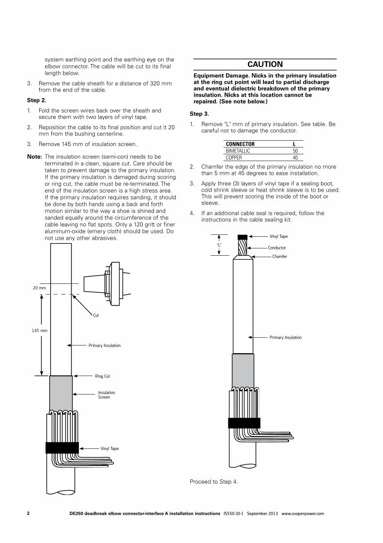
system earthing point and the earthing eye on the elbow connector. The cable will be cut to its final length below.
3. Remove the cable sheath for a distance of 320 mm from the end of the cable.
step 2.
1. Fold the screen wires back over the sheath and secure them with two layers of vinyl tape.
2. Reposition the cable to its final position and cut it 20 mm from the bushing centerline.
3. Remove 145 mm of insulation screen.
ote:n The insulation screen (semi-con) needs to be terminated in a clean, square cut. Care should be taken to prevent damage to the primary insulation. If the primary insulation is damaged during scoring or ring cut, the cable must be re-terminated. The end of the insulation screen is a high stress area. If the primary insulation requires sanding, it should be done by both hands using a back and forth motion similar to the way a shoe is shined and sanded equally around the circumference of the cable leaving no flat spots. Only a 120 gritt or finer aluminum-oxide (emery cloth) should be used. Do not use any other abrasives.
step 3.
1. Remove "L" mm of primary insulation. See table. Be careful not to damage the conductor.
2. Chamfer the edge of the primary insulation no more than 5 mm at 45 degrees to ease installation.
3. Apply three (3) layers of vinyl tape if a sealing boot, cold shrink sleeve or heat shrink sleeve is to be used. This will prevent scoring the inside of the boot or sleeve.
4. If an additional cable seal is required, follow the instructions in the cable sealing kit.
Proceed to Step 4.
CONNECTOR LBIMETALLIC 50COPPER 40
cautionequipment damage. nicks in the primary insulation at the ring cut point will lead to partial discharge and eventual dielectric breakdown of the primary insulation. nicks at this location cannot be repaired. (see note below.)
Primary Insulation
Conductor
20 mm
Vinyl Tape
Cut
Vinyl Tape
"L"
Chamfer
Insulation Screen
145 mmPrimary Insulation
Ring Cut
2 DE250 deadbreak elbow connector-interface A installation instructions IS550-10-1 September 2013 www.cooperpower.com

step 4.
1. Remove vinyl tape before installing connector.
2. If the conductor is aluminum, thoroughly wire brush the exposed conductor.
3. Immediately insert the conductor into the crimp barrel as far as it will go. Ensure that the flat surface of the compression connector faces the bushing.
4. Crimp the connector starting at the shoulder, as shown. Rotate the crimping tool 90 degrees for each successive crimp. See Crimp Chart on page 4.
5. Remove any excess inhibitor that may have come out of the connector. Wipe the excess inhibitor towards the eye of the connector.
6. Remove any sharp edges after crimping.
step 5.
1. Clean the insulation with a lint-free cloth and a suitable cleaner.
2. Apply a thin layer of lubricant to the primary insulation of the cable and the interior of the cable end of the moulded elbow housing
3. Push the elbow onto the cable as far as it will go. Ensure that the threaded hole of the connector is visible through the interface end of the elbow.
19.6-24.1 M
M F
DE
25
02
50
A2
4 k
V
.770-.950 IN
4 3
2
1
4 3
2
1
4 3
2
1
Lubricate
3DE250 deadbreak elbow connector-interface A installation instructions IS550-10-1 September 2013 www.cooperpower.com

step 6.
1. Insert the probe into the threaded hole of the connector. Ensure that the threads are not crossed.
2. Tighten the probe with the supplied hex wrench. The proper torque is reached when the hex key has bent 90° to 180°.
3. Connect one of the screen wires to the earthing eye on the elbow.
4. Connect the screen wires to earth.
step 7.
1. Clean the bushing and connector interfaces and apply a thin layer of lubricant to each.
2. Push the elbow onto the bushing until it is fully seated.
step 8.
1. Hook the legs of the bail assembly onto the bail tabs on the bushing or bushing clamp. Thread the eyebolt of the bail assembly tight against the back of the pulling eye of the elbow.
19.6-24.1 M
M F
DE
25
02
50
A2
4 k
V
.770-.950 IN
4 3
2
1
19.6-24.1 M
M F
DE
25
02
50
A2
4 k
V
.770-.950 IN
ProbeHex Key
Lubricate
table 1. crimp chartCatalog Number Material Cable Size mm2 Die IndexCDE250P16 Bimetallic - plated
16
16
CDE250U16 BimetallicCDE250C16 CopperCDE250P25 Bimetallic - plated
25CDE250U25 BimetallicCDE250C25 CopperCDE250P35 Bimetallic - plated
35CDE250U35 BimetallicCDE250C35 CopperCDE250P50 Bimetallic - plated
50CDE250U50 BimetallicCDE250C50 CopperCDE250P70 Bimetallic - plated
70 18CDE250U70 BimetallicCDE250C70 CopperCDE250P95 Bimetallic - plated
95 20CDE250U95 BimetallicCDE250C95 CopperCDE250P120 Bimetallic - plated
120 22CDE250U120 BimetallicCDE250C120 Copper
4 DE250 deadbreak elbow connector-interface A installation instructions IS550-10-1 September 2013 www.cooperpower.com

caution: The apparatus bushing and elbow connector should not support the weight of the cable. Clamp the cable immediately below the cable screen adapter. Failure to comply may result in equipment damage.
WarninG capacitive test point operating instructions. use only voltage indicating instruments specifically designed for test points. use of conventional voltage sensing devices may provide false "no Voltage" indications.
the test point must be dry and free of contaminants when checking for voltage. after indication is taken; clean, dry, and lubricate the test point cap with silicone grease and assemble to test point.
the capacitive test point is not sufficiently accurate, nor is it intended for actual voltage measurements or phasing operations.
a reading of no voltage from the test point should not be the only indication of a de-energized circuit obtained before touching the connector. other procedures can include direct conductor voltage testing or grounding using a live-line tool.
Stainless Steel BailPulling Eye
Bail Tab
Optional Spring Bail
Optional spring bail1. Hook the legs of the bail assembly into the tabs of
the bushing flange. Lift the bail from the lifting eye and center it on the back of the pulling eye of the elbow.
5DE250 deadbreak elbow connector-interface A installation instructions IS550-10-1 September 2013 www.cooperpower.com

This page intentionally left blank.
6 DE250 deadbreak elbow connector-interface A installation instructions IS550-10-1 September 2013 www.cooperpower.com

7DE250 deadbreak elbow connector-interface A installation instructions IS550-10-1 September 2013 www.cooperpower.com

Eaton and Cooper Power Systems are valuable trademarks of Eaton, in the U.S. and other countries. You are not permitted to use these trademarks without the prior written consent of Eaton.
Eaton1000 Eaton BoulevardCleveland, OH 44122United StatesEaton.com
Eaton’s Cooper Power Systems Business2300 Badger DriveWaukesha, WI 53188cooperpower.com
© 2013 EatonAll Rights ReservedPrinted in USAPublication No. IS550101 Rev 01 (Replaces IS550101 Rev 00)
!SAFETYFOR LIFE