Is.15395.Industrial AC Networks Affected by Harmonic Application of Filters & Shunt Capacitors
34
Disclosure to Promote the R ight To Information Whereas the Parliament of India has set out to provide a practical regime of right to information for citizens to secure access to information under the control of public authorities, in order to promote transparency and accountability in the working of every public authority, and whereas the attached publication of the Bureau of Indian Standards is of particular interest to the public, particularly disadvantaged communities and those engaged in the pursuit of education and knowledge, the attached public safety standard is made available to promote the timely dissemination of this information in an accurate manner to the public. !" #$%& # '(%) “ !"# $ %& #' (")* &" +#,-. ” Satyanarayan Gangaram Pitroda “Invent a New India Using Knowledge” “ /0 )"1 &2 324 #' 5 *)6 ” Jawaharlal Nehru “Step Out From the Old to the New” “ 7"#1 &" 8+9&") , 7:1 &" 8+9&") ” Mazdoor Kisan Shakti Sangathan “The Right to Information, The Right to Live” “ !"# %& ;<" =7"#" > 72 &(: ?0 )"@" #AB 7" <&*" A * ” Bhart+hari—N,ti-atakam “Knowledge is such a treasure which cannot be stolen” IS 15395 (2003): Industrial Ac Networks Affected by Harmonics Application of Filters and Shunt Capacitors [ETD 29: Power Capacitors]
-
Upload
srikanth-voleti -
Category
Documents
-
view
223 -
download
0
Transcript of Is.15395.Industrial AC Networks Affected by Harmonic Application of Filters & Shunt Capacitors

8/12/2019 Is.15395.Industrial AC Networks Affected by Harmonic Application of Filters & Shunt Capacitors
http://slidepdf.com/reader/full/is15395industrial-ac-networks-affected-by-harmonic-application-of-filters 1/33
Disclosure to Promote the Right To Information
Whereas the Parliament of India has set out to provide a practical regime of right to
information for citizens to secure access to information under the control of public authorities,in order to promote transparency and accountability in the working of every public authority,
and whereas the attached publication of the Bureau of Indian Standards is of particular interest
to the public, particularly disadvantaged communities and those engaged in the pursuit of
education and knowledge, the attached public safety standard is made available to promote the
timely dissemination of this information in an accurate manner to the public.
!"#$%&# '(%)
“ !"# $ %& #' (")* &" +#,-. ”Satyanarayan Gangaram Pitroda
“Invent a New India Using Knowledge”
“ /0 )"1 &2 324 #' 5 *)6 ” Jawaharlal Nehru
“Step Out From the Old to the New”
“ 7"#1 &" 8+9&") , 7:1 &" 8+9&") ”Mazdoor Kisan Shakti Sangathan
“The Right to Information, The Right to Live”
“ !"# %& ;<" =7"#" > 72 &(: ?0 )"@" #AB 7" <&*" A *”Bhart+hari—N,ti-atakam
“Knowledge is such a treasure which cannot be stolen”
IS 15395 (2003): Industrial Ac Networks Affected by
Harmonics Application of Filters and Shunt Capacitors [ETD
29: Power Capacitors]

8/12/2019 Is.15395.Industrial AC Networks Affected by Harmonic Application of Filters & Shunt Capacitors
http://slidepdf.com/reader/full/is15395industrial-ac-networks-affected-by-harmonic-application-of-filters 2/33
8/12/2019 Is.15395.Industrial AC Networks Affected by Harmonic Application of Filters & Shunt Capacitors
http://slidepdf.com/reader/full/is15395industrial-ac-networks-affected-by-harmonic-application-of-filters 3/33
8/12/2019 Is.15395.Industrial AC Networks Affected by Harmonic Application of Filters & Shunt Capacitors
http://slidepdf.com/reader/full/is15395industrial-ac-networks-affected-by-harmonic-application-of-filters 4/33
IS 15395:2003
IEC 61642 (1997)
w-ma ‘m WTfarr 3?Eim*? qQ%+lt zl -
./ (m aywi’1 ‘rii’l?%Hwlf?5
hdan skmhrd
INDUSTRIAL AC NETWORKS AFFECTED BY
HARMONICS APPLICATION OF FILTERS
AND SHUNT CAPACITORS
ICS 29.120.99; 29.240.99; 31.060.70
@ 61S 2003
BUREAU OF INDIAN STANDARDS
MANAK BHAVAN, 9 BAHADUR SHAH ZAFAR MARG
NEW DELHI 110002
October 2003 Price Group 10
8/12/2019 Is.15395.Industrial AC Networks Affected by Harmonic Application of Filters & Shunt Capacitors
http://slidepdf.com/reader/full/is15395industrial-ac-networks-affected-by-harmonic-application-of-filters 5/33
Power Capacitor Sectional Committee, “ET 29
NATIONAL FOREWORD
This Indian Standard which is identical with IEC 61642 ( 1997 ) ‘Industrial a.c. networks affected byharmonics — Application of filters and shunt capacitors’ issued by the International Electrotechnical
Commission ( IEC ) was adopted by the Bureau of Indian Standards on the recommendations of the
Power Capacitor Sectional Committee and approval of the Electrotechnical Division Council.
The text of the IEC Standard has been approved as suitable for publication as an Indian Standard
without deviations. Certain conventions are, however, not identical to those used in Indian standards.
Attention is particularly drawn to the following:
a) Wherever the words ‘International Standard’ appear referring to this standard, they should be
read as ‘Indian Standard’; and
b) Comma ( , ) has been used as a decimal marker, while in Indian Standards, the current practice
is to use a point ( . ) as the decimal marker.
CROSS REFERENCES
In this adopted standard, references appear to certain International Standards for which Indian
Standards also exist. The corresponding Indian Standards, which are to be substituted in their
respective places are listed below along with their degree of equivalence for the editions indicated:
International Standard Indian Standard Degree of Equivalence
IEC 60050( 131 ) :1978 International IS 1885( Part 57 ) 1992 Elecrotechnical Identical
Electrotechnical Vocabulary ( IEV ) vocabulary : Part 57 Electric and
Chapter 131: Electric and magnetic magnetic circuitscircuits
IEC 60050( 161 ): 19 30 International IS 1885 ( Part 64/ Sec 1 ) :1987 Technically
Electrotechnical Vocabulary Electrotechnical vocabulary: Part 64 equivalent
( tEV ) – Chapter 161 : Electromagnetic compatibility,
Electromagnetic compatibility Section 1 General terms
Only the English text of the International Standard has been retained while adopting it as an Indian
Standard.
For the purpose of deciding whether a particular requirement of this standard is complied with, the
final value, observed or calculated, expressing the result of a test, shall be rounded off in accordance
with IS 2:1960 ‘Rules for rounding of numerical values ( revised )’. The number of significant placesretained in the rounded off value should be the same as that of the specified value in this standard.
8/12/2019 Is.15395.Industrial AC Networks Affected by Harmonic Application of Filters & Shunt Capacitors
http://slidepdf.com/reader/full/is15395industrial-ac-networks-affected-by-harmonic-application-of-filters 6/33
IS 15395:2003
IEC 61642(1997)
indi n t nd rd
INDUSTRIAL AC NETWORKS AFFECTED BY
HARMONICS APPLICATION OF FILTERS
1 GeneralAND SHUNT CAPACITORS
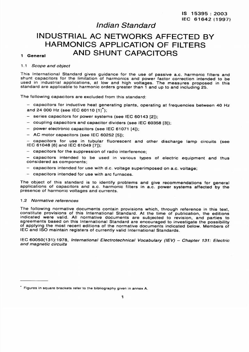
1.1 Scope and object
This International Standard gives guidance -for the use of passive a.c. harmonic filters and
shunt capacitors for the limitation of harmonics and power factor correction intended to be
used in industrial applications, at low and high voltages. The measures proposed in this
standard are applicable-to harmonic orders greater than 1 and up to and including 25.
The following capacitors are excluded from this standard:
– capacitors for inductive heat generating plants, operating at frequencies between 40 Hz
and 24000 Hz (see IEC 60110 [1]*);
—
series capacitors for power systems (see IEC 60143 [2]);
coupling capacitors and capacitor dividers (see IEC 60358 [3]);
power electronic capacitors (see IEC 61071 [4]);
AC motor capacitors (see IEC 60252 [5]);
capacitors for use in tubular fluorescent and other discharge lamp circuits (see
IEC 61048 [6] and IEC 61049 [7]);
— capacitors for the suppression of radio interference;
– capacitors intended to be used in various types of electric equipment and thus
considered as components;
– capacitors intended for use with d.c. voltage superimposed on a:c. voltage;
– capacitors intended for use with arc furnaces.
The object of this standard is to identify problems and give recommendations for general
applications of capacitors and a.c. harmonic filters in a.c. power systems affected by the
presence of harmonic voltages and currents.
1.2 Normative references
The following normative documents contain provisions which, through reference in this text,
constitute provisions of this International Standard. At the time of publication, the editions
indicated were valid. All normative documents are subjected to revision, and parties to
agreements based on this International Standard are encouraged to investigate the possibility
of applying the most recent editions of the normative documents indicate-d below. Members of
.IEC and ISO maintain registers of currently valid International Standards.
IEC 60050(1 31):1978, /ntemationa/ E/ectrotechnica/ Vocabulary (IEV) – Chapter 137: E/ectric
and magnetic circuits
“ Figures in square brackets refer to the bibliography given in annex A.
1
8/12/2019 Is.15395.Industrial AC Networks Affected by Harmonic Application of Filters & Shunt Capacitors
http://slidepdf.com/reader/full/is15395industrial-ac-networks-affected-by-harmonic-application-of-filters 7/33
IS 15395:2003
IEC 61642(1997)
IEC 60050(161):1990, /rttemationa/ E/ectrotechnica/ Vocabulary (/EV) – Chapter 161: Electro-
magnetic compatibility
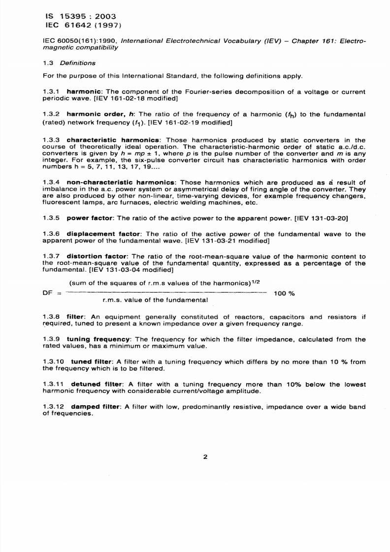
1.3 Definitions
For the purpose of this
1.3.1 harmonic: The
International Standard, the following definitions apply.
component of the Fourier-series decomposition of a voltage or current
periodic wave. [IEV 161-02-18 modified]
1.3.2 harmonic order, h: The ratio of the frequency of a harmonic (fh) to the fundamental
(rated) network fre-quency (fl ). [IEV 161-02-19 modified]
1.3.3 characteristic harmonics: Those harmonics produced by static converters in the
course of theoretically ideal operation. The characteristic-harmonic order of static a.c./d.c.
converters is given by h = mp * 1 where p is the pulse number of the converter and m is any
integer. For example, the six-pulse converter circuit has characteristic harmonics with ordernumbers h = 5, 7, 11, 13, 17, 19 ....
1.3.4 non-characteristic harmonics: Those harmonics which are produced as a result of
imbalance in the a.c. power system or asymmetrical delay of firing angle of the converter. They
are also produced by other non-linear, time-varying devices, for example frequency changers,
fluorescent lamps, arc furnaces, electric welding machines, etc.
1.3.5 power factor: The ratio of the active power to the apparent power. [IEV 13-
1.3.6 displacement factor: The ratio of the active power of the fundamental
apparent power of the fundamental wave. [IEV 131-03-21 modified]
1.3.7 distortion -factor: The ratio of the root-mean-sauare value of the harmor
-03-20]
wave to the
c content tothe root-mean-square value of the fundamental quanti&, expressed as a Percentafje Of the
fundamental. [IEV 131-03-04 modified].
(sum of the squares of r.m.s values of-the harmonics) l/2
~~ . .––—––__––________–__‘––——–– 10070
r.m. s. value of the fundamental
1.3.8 filter: An equipment generally constituted of reactors, capacitors
required, tuned to present a known impedance over a given frequency range.
and resistors if
1.3.9 tuning frequency: The frequency for which the filter impedance, calculated from the
rated values, has a minimum or maximum value.
1.3.10 tuned filter: A filter with a tuning frequency which differs by no more than 10 Y. from
the frequency which is to be filtered.
1.3.11 detuned filter: A filter with a tuning frequency more than 10 below the lowest
harmonic frequency with considerable current/voltage amplitude.
1.3.12 damped filter: A filter with low, predominantly resistive, impedance over a wide bandof frequencies.
8/12/2019 Is.15395.Industrial AC Networks Affected by Harmonic Application of Filters & Shunt Capacitors
http://slidepdf.com/reader/full/is15395industrial-ac-networks-affected-by-harmonic-application-of-filters 8/33
IS 15395:2003
IEC 61642 (1997)
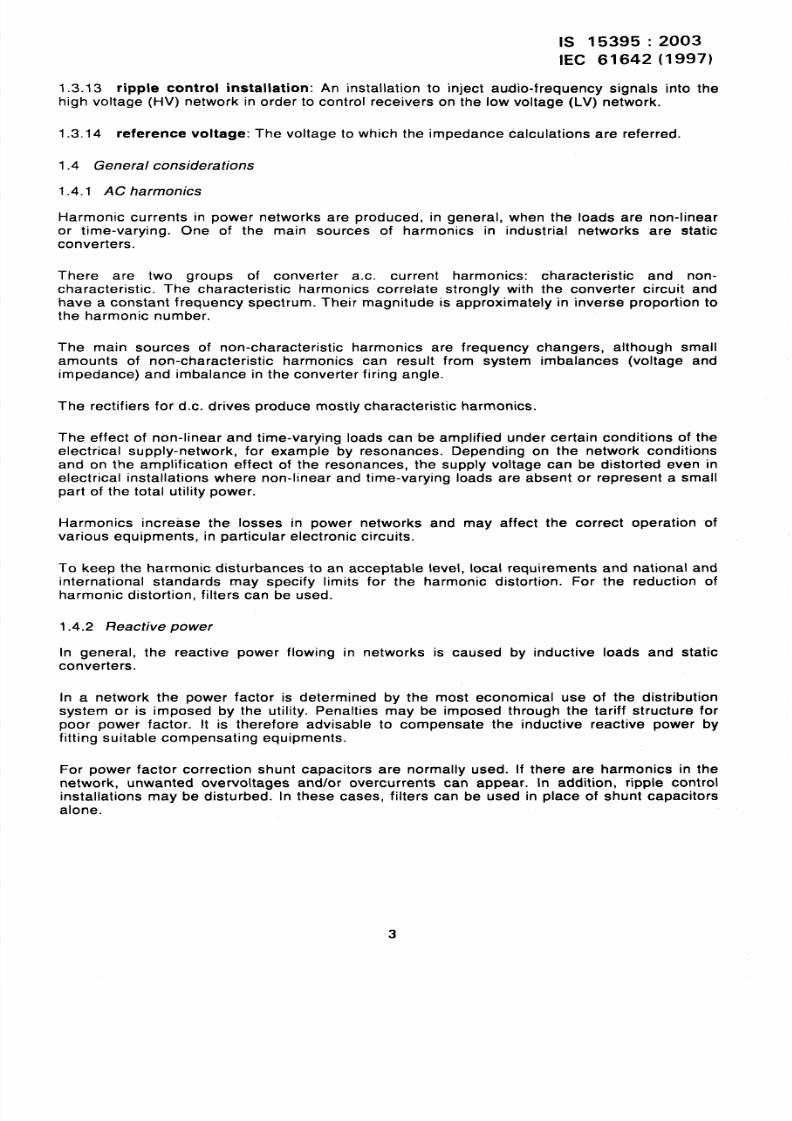
1.3.13 ripple control installation: An installation to inject audio-frequency signals into the
high voltage (HV) network in order to control receivers on the low voltage (LV) network.
1.3.14 reference voltage: The voltage to which the impedance calculations are referred.
1.4 General considerations
1.4.1 AC harmonics
Harmonic currents in power networks are produced, in general, when the loads are non-linear
or time-varying. One of the main sources of harmonics in industrial networks are static
converters.
There are two groups of converter a.c. current harmonics: characteristic and non-
characteristic. The characteristic harmonics correlate strongly with the converter circuit and
have a constant frequency spectrum. Their magnitude is approximately in inverse proportion to
the harmonic number.
The main sources of non-characteristic harmonics are frequency changers, although small
amounts of non-characteristic harmonics can result from system imbalances (voltage and
impedance) and imbalance in the converter firing angle.
The rectifiers for d.c. drives produce mostly characteristic harmonics.
The effect of non-linear and time-varying loads can be amplified under certain conditions of the
electrical supply-network, for example by resonances. Depending on the network conditions
and on the amplification effect of the resonances, the supply voltage can be distorted even in
electrical installations where non-linear and time-varying loads are absent or represent a small
part of the total utility power.
Harmonics increase the losses in power networks and may affect the correct operation ‘of
various equipments, in particular electronic circuits.
To keep the harmonic disturbances to an acceptable level, local requirements and national and
international standards may specify limits for the harmonic distortion. For the reduction of
harmonic distortion, filters can be used.
1.4.2 Reactive power
In general, the reactive power flowing in networks is caused by inductive loads and static
converters.
In a network the power factor is determined by the most economical use of the distribution
system or is imposed by the utility. Penalties may be imposed through the tariff structure for
poor power factor. It is therefore advisable to compensate the inductive reactive power by
fitting suitable compensating equipments.
For power factor correction shunt capacitors are normally used. If there are harmonics in the
network, unwanted overvoltages and/or overcurrents can appear. In addition, ripple control
installations may be disturbed. In these cases, filters can be used in place of shunt capacitors
alone.
3
8/12/2019 Is.15395.Industrial AC Networks Affected by Harmonic Application of Filters & Shunt Capacitors
http://slidepdf.com/reader/full/is15395industrial-ac-networks-affected-by-harmonic-application-of-filters 9/33
IS 15395:2003
IEC 61642(1997)
2 Resonance problems and solutions
2.1 Mmduction
In electrical networks, different components are connected together, for example generators,
power lines, cables, transformers, capacitors and loads.
The impedance at any point of the network is dependent on the frequency, on the components
and on the configuration.
The series connection of an inductance and a capacitance will result in a very low impedance
in a certain frequency range, close to the resonance frequency. This effect is called series
resonance.
The parallel connection of an inductance and a capacitance will result in a very high impedance
in a certain frequency range, close to the resonance frequency. This effect is called parallel
resonance.
Series resonance and parallel resonance may occur in the same network over a wide range of
frequencies.
If harmonic voltage- or current-sources excite such resonance circuits, an amplification -of
voltages and currents may occur which can disturb, overload or even destroy network
components.
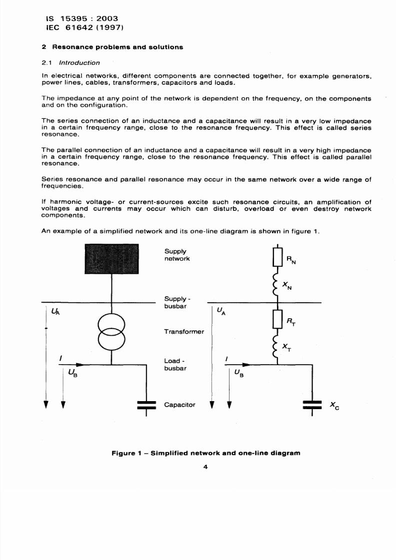
An example of a simplified network and its one-line diagram is shown in figure 1.
supply
network
RN
XN
SUDDIV-—-rr,I
u~
ebusbar
Transformer
I I
I
1-
Load -
busbar
Capacitor
UA
RT
/
I
LIB
- r
xc
Figure 1- Simplified network and one-line diagram
4
8/12/2019 Is.15395.Industrial AC Networks Affected by Harmonic Application of Filters & Shunt Capacitors
http://slidepdf.com/reader/full/is15395industrial-ac-networks-affected-by-harmonic-application-of-filters 10/33
IS 15395:2003
IEC 61642 (1997)
This example consists of the supply network, a supply-busbar (on the high-voltage side), a
transformer, a Ioad-busbar .(on the low-voltage side) and a capacitor. The source of harmonic
currents may be a drive which is controlled by a six-pulse rectifier. Harmonic voltages may be
present in the network itself due to other harmonic current sources.
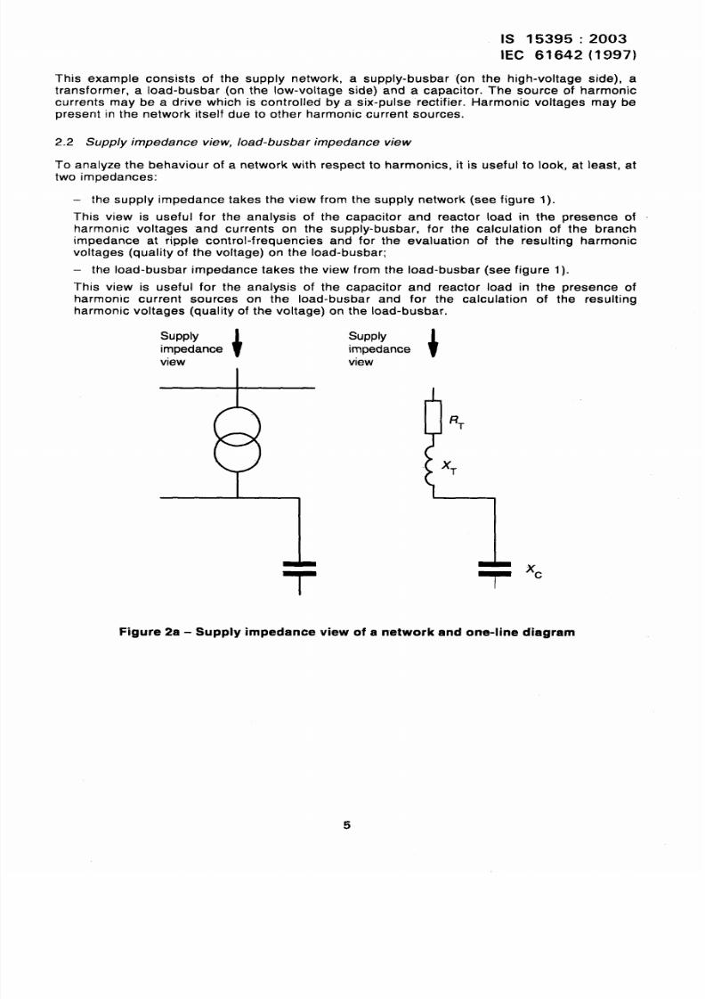
2.2 Supply impedance vie w, Ioad-busbar impedance view
To analyze the behaviour of a network with respect to harmonics, it is useful to look, at least, at
two impedances:
– the supply impedance takes the view from the supply network (see figure 1).
This view is useful for the analysis of the capacitor and reactor load in the presence of
harmonic voltages and currents on the supply-busbar, for the calculation of the branch
impedance at rippIe control-frequencies and for the evaluation of the resulting harmonic
voltages (quality of the voltage) on the Ioad-busbar;
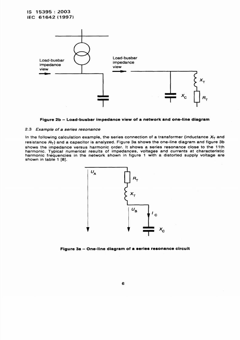
– the Ioad-busbar impedance takes the view from the Ioad-busbar (see figure 1).
This view is useful for the analysis of the capacitor and reactor load in the presence of
harmonic current sources on the Ioad-busbar and for the calculation of the resulting
harmonic voltages (quality of the voltage) on the Ioad-busbar.
supply
impedancei
view
supply
impedancei
view
xc
Figure 2a - Supply impedance view of a network and one-line diagram
5
8/12/2019 Is.15395.Industrial AC Networks Affected by Harmonic Application of Filters & Shunt Capacitors
http://slidepdf.com/reader/full/is15395industrial-ac-networks-affected-by-harmonic-application-of-filters 11/33
IS 15395:2003
IEC 61642 (1997)
Load-busbar
impedance
view
Load-busbar
impedance
view
-rxc
RT
Figure 2b - Load-busbar impedance view of a network and one-line diagram
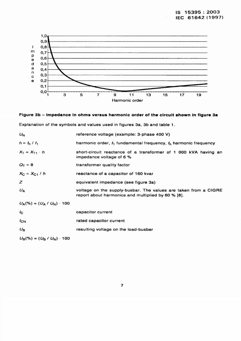
2.3 Example of a series resonance
In the following calculation example, the series connection of a transformer (inductance XT and
resistance ~) and a capacitor is analyzed. Figure 3a shows the one-line diagram and figure 3b
shows the impedance versus harmonic order. It shows a series resonance close to the 1Ith
harmonic. Typical numerical results of impedances, voltages and currents at characteristicharmonic frequencies in the network shown in figure 1 with a distorted supply voltage are
shown in table 1 [8].
UA
1
RT
I’ B
1
- r
c
xc
Figure 3a - One-line diagram of a series resonance circuit
6
8/12/2019 Is.15395.Industrial AC Networks Affected by Harmonic Application of Filters & Shunt Capacitors
http://slidepdf.com/reader/full/is15395industrial-ac-networks-affected-by-harmonic-application-of-filters 12/33
IS 15395:2003
IEC 61642(1997)
I 0,8
e
d 0,5
a 0,4”n
c 0,3”-
e 0,2”-
0,1”-
0,01 3 5 7 9 11 13 15 17 19
Harmonic order
Figure 3b - Impedance in ohms versus harmonic order of the circuit shown in figure 3a
Explanation of the symbols and values used in figures 3a, 3b and table 1.
UN
h= fh/fl
XT= XTlh
Q=8
Xc= XCl/h
z
UA
UA ?O= UA UN . 100
I(-J
/cN
@
UB( ) = (“UB/ UN) .100
reference voltage (example: 3-phase 400 V)
harmonic order, fl fundamental freqUenCy, fh
short-circuit reactance of a transformer of
harmonic frequency
1 000 kVA having an
impedance voltage of 6 YO
transformer quality factor
reactance of a capacitor of
equivalent impedance (see
160 kvar
figure 3a)
voltage on the supply-busbar. The values are taken from a CIGRE
report about harmonics and multiplied by 60 YO[8].
capacitor current
rated capacitor current
resulting voltage on the Ioad-busbar
8/12/2019 Is.15395.Industrial AC Networks Affected by Harmonic Application of Filters & Shunt Capacitors
http://slidepdf.com/reader/full/is15395industrial-ac-networks-affected-by-harmonic-application-of-filters 13/33
IS 15395:2003
IEC 61642 (1997)
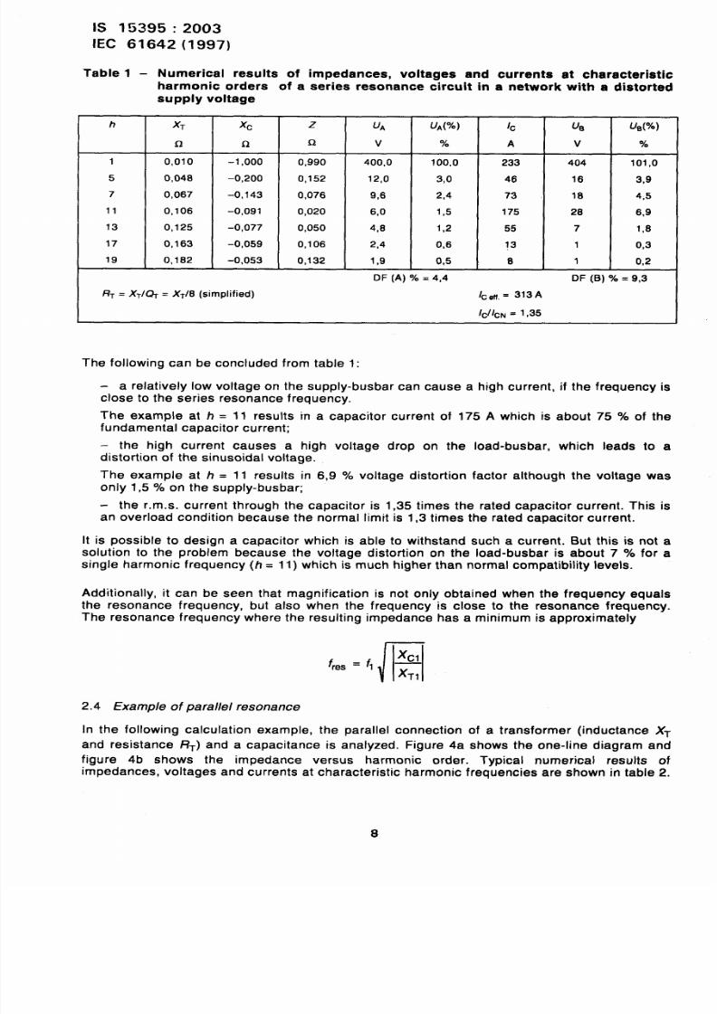
Table 1 - Numerical results of impedances, voltages and
harmonic orders of a series resonance &cuit in
h
1
5
7
11
13
17
19
supply voltage
X7
Q
0,010
0,048
0,067
0,106
0,125
0,163
0,182
xc
Q
-1,000
-0,200
-0,143
-0,091
-0,077
-0,059
-0,053
RT= XT/~ = XT/8 (simplified)
z
Q
0,990
0,152
0,076
0,020
0,050
0,106
0,132
u~
v
400,0
12,0
9,6
6,0
4,6
2,4
1,9
DF (A) = 4,4
currents at characteristic
a network with a distorted
1~
A
233
46
73
175
55
13
6
I=efi,= 313A
ICIICN= 1,35
UA(?”O)
%
100,0
3,0
2,4
1,5
1,2
0,6
0,5
u~
v
404
16
16
26
7
1
1
u~(%)
%0
101,0
3,9
4,5
6,9
1,6
0,3
0,2
DF (B) = 9,3
The following can be concluded from table 1:
- a relatively low voltage on the supply-busbar can cause a high current, if the frequency is
It
close to the series resonance frequency.
The example at h = 11 results m a capacitor current of 175 A which is about 75 of the
fundamental capacitor current;
- the high current causes a high voltage drop on the Ioad-busbar, which leads to adistortion of the sinusoidal voltage.
The example at h = 11 results in 6,9 voltage distortion factor although the voltage was
only 1,5 ‘XOon the supply -busbar;
- the r.m.s. current through the capacitor is 1,35 times the rated capacitor current. This is
an overload condition because the normal limit is 1,3 times the rated capacitor current.
is possible to desian a capacitor which is able to withstand such a current. But this is not a
soiufion to the probl;m because the voltage distortion on the Ioad-busbar is about 7 VOfor a
single harmonic frequency (h = 11) which is much higher than normal compatibility levels.
Additionally, it can be seen that magnification is not only obtained when the frequency equals
the resonance frequency, but also when the frequency is close to the resonance frequency.
The resonance frequency where the resulting impedance has a minimum is approximately
f
r
Xclres =Q —
XT,
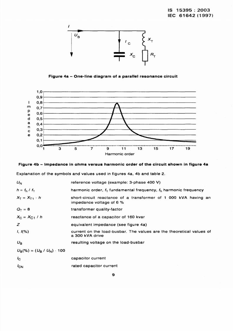
2.4 Example of parallel resonance
In the following calculation example, the parallel connection of a transformer (inductance X-
and resistance F?T) and a capacitance is analyzed. Figure 4a shows the one-line diagram and
figure 4b shows the impedance versus harmonic order. Typical numerical results of
impedances, voltages and currents at characteristic harmonic frequencies are shown in table 2.
8
8/12/2019 Is.15395.Industrial AC Networks Affected by Harmonic Application of Filters & Shunt Capacitors
http://slidepdf.com/reader/full/is15395industrial-ac-networks-affected-by-harmonic-application-of-filters 14/33
8/12/2019 Is.15395.Industrial AC Networks Affected by Harmonic Application of Filters & Shunt Capacitors
http://slidepdf.com/reader/full/is15395industrial-ac-networks-affected-by-harmonic-application-of-filters 15/33
iS 15395:2003
IEC 61642 (1997)
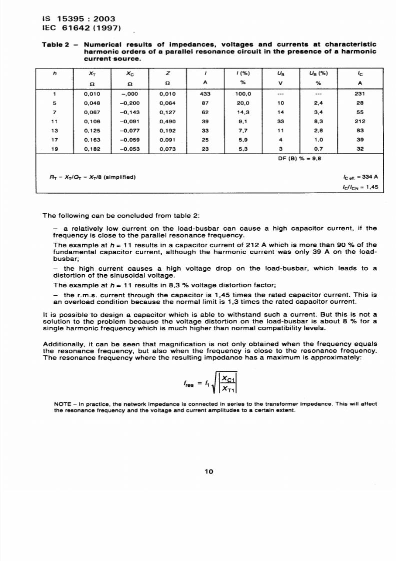
Table 2 - Numerical results of impedances, voltages and currents at characteristic
harmonic orders of a parallel resonance circuit in the presence of a harmonic
current ‘SOUrce.
h XT xc z / / ( ) us u~ (%) 1~
$-2 Q Q A ‘Y. v A
1 0,010 -,000 0,010 433 100,0 ..- ... 231
5 0,048 -0,200 0,064 67 20,0 10 2,4 28
7 0,067 -0,143 0,127 62 +4,3 14 3,4 55
11 0,106 -0,091 1 ,490 39 9,1 33 8,3 212
13 0,125 -0,077 0,192 33 7,7 11 2,6 63
17 0,163 -0,059 0,091 25 5,9 4 1,0 39
19 0,182 –0,053 0,073 23 5,3 3 0,7 32
DF (B) = 9,8
RT= XT/~ = XT/8 (simplified) Ic,ti, = 334A
lclic~ = 1,45
The following can be concluded from table 2:
— a relatively low current on the Ioad-busbar can cause a high capacitor current, if the
frequency is close to the parallel resonance frequency.
The example at h = 11 results in a capacitor current of 212 A which is more than 90 of thefundamental capacitor current, although the harmonic current was only 39 A on the load-
busbar;
– the high current causes a high voltage drop on the load-busbar, which I.cads to a
distortion of the sinusoidal voltage.
The example at h = 11 results in 8,3 voltage distortion factor;
— the r.m.s. current through the capacitor is 1,45 times the rated capacitor current. This is
an overload condition because the normal limit is 1,3 times the rated capacitor current.
It is possible to design a capacitor which is able to withstand such a current. But this is not a
solution to the problem because the voltage distortion on the Ioad-busbar is about 8 YOfor a
single harmonic frequency which is much higher than normal compatibility levels.
Additionally, it can be seen that magnification is not only obtained when the frequency equals
the resonance frequency, but also when the frequency is close to the resonance frequency.
The resonance frequency where the resulting impedance has a maximum is approximately:
/
Xclfres = f, —
XT,
NOTE- In practice, the network impedance is connected in series to the transformer impedance. This will affect
the resonance frequency and the voltage and current amplitudes to a certain extent.
10
8/12/2019 Is.15395.Industrial AC Networks Affected by Harmonic Application of Filters & Shunt Capacitors
http://slidepdf.com/reader/full/is15395industrial-ac-networks-affected-by-harmonic-application-of-filters 16/33
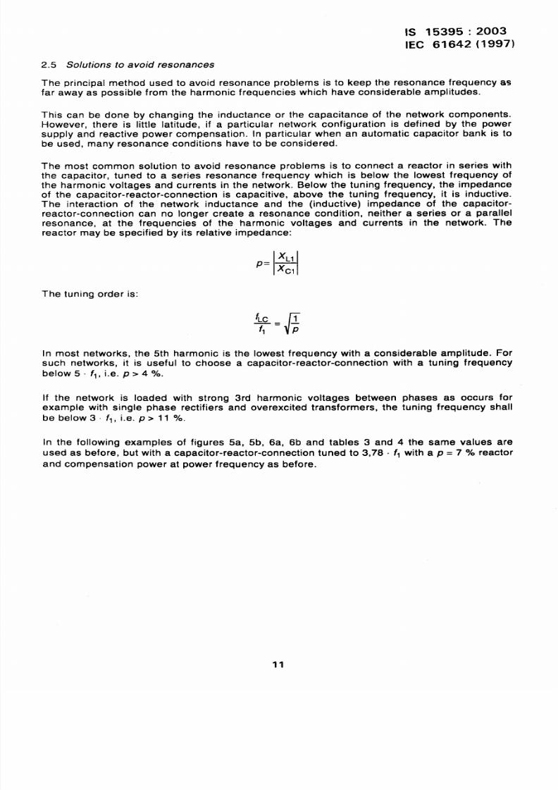
2.5
The
Solutions to avoid resonances
principal method used to avoid
IS 15395:2003
IEC 61642 (1997)
resonance problems is to keep the resonance frequency as
far away as possible from the harmonic frequencies which have considerable amplitudes.
This can be done by changing the inductance or the capacitance of the network components.However, there is little latitude, if a particular network configuration is defined by the power
supply and reactive power compensation. In particular when an automatic capacitor bank is to
be used, many resonance conditions have to be considered.
The most common solution to avoid resonance problems is to connect a reactor in series with
the capacitor, tuned to a series resonance frequency which is below the lowest frequency of
the harmonic voltages and currents in the network. Below the tuning frequency, the impedance
of the capacitor-reactor-connection is capacitive, above the tuning frequency, it is inductive.
The interaction of the network inductance and the (inductive) impedance of the capacitor-
reactor-connection can no longer create a resonance condition, neither a series or a parallel
resonance, at the frequencies of the harmonic voltages and currents in the network. The
reactor may be specified by its relative impedance:
‘L1P= ~
The tuning order is:
In most networks, the 5th harmonic is the
[
‘LC ~
~= p
lowest freauencv with a considerable amplitude. For
such networks, it is useful to choose a capacitor-reactor~connection with a tuning frequency
below 5. f,, i.e. p >4 /o.
If the network is loaded with strong 3rd harmonic voltages between phases as occurs for
example with single phase rectifiers and overexcited transformers, the tuning frequency shall
be below3 f,, i.e. p> 11 Yo.
In the following examples of figures 5a, 5b, 6a, 6b and tables 3 and 4 the same values are
used as before, but with a capacitor-reactor-connection tuned to 3,78. fl with a p = 7 ? oreactor
and compensation power at power frequency as before.
11
8/12/2019 Is.15395.Industrial AC Networks Affected by Harmonic Application of Filters & Shunt Capacitors
http://slidepdf.com/reader/full/is15395industrial-ac-networks-affected-by-harmonic-application-of-filters 17/33
IS 15395:2003
IEC 61642 (1997)
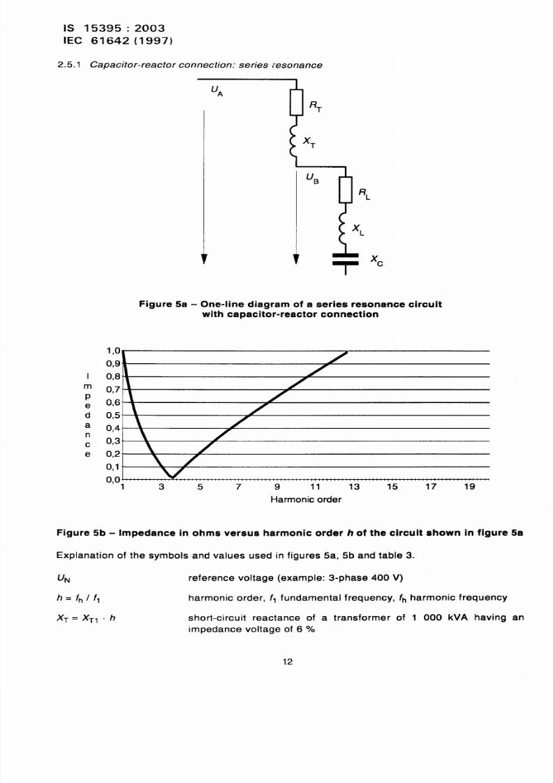
2.5.1 Capacitor-reactor connection: series resonance
I
m
Pe
d
a
n
c
e
UA
RL
RT
LIB
TT
xc
Figure 5a - One-line diagram of a series resonance circuit
with capacitor-reactor connection
1, 0
0,9”
0,8
0,7’ ‘
0,5”
0,4” \
0,3” -
0,2’ ‘ \ H0, 1 \ /
0, 0“: ’ ’ : ’ : ’ ”1 3 5 7 9 11 13 15 17 19
Harmonic order
Figure 5b - Impedance in ohms versus harmonic order h of the circuit shown in figure 5a
Explanation of the symbols and values used in figures 5a, 5b and table 3.
UN reference voltage (example: 3-phase 400 V)
h= t-~/f, harmonic order, f, fundamental frequency, fh harmonic frequency
X~=XT1-h short-circuit reactance of a transformer of 1 000 kVA having an
impedance voltage of 6 YO
12
8/12/2019 Is.15395.Industrial AC Networks Affected by Harmonic Application of Filters & Shunt Capacitors
http://slidepdf.com/reader/full/is15395industrial-ac-networks-affected-by-harmonic-application-of-filters 18/33
IS 15395:2003
IEC 61642(1997)
(+.8
XL+xc
Q~ = 30
z
u~
u~( )=(UA/UN). 100
1~ capacitor current
1~~ rated capacitor current
u~ resulting vottage on the Ioad-busbar
u~( )=(UB/UJ . 100
transformer quality factor
reactance of a capacitor with a p = 7 YO reactor for 160 kvar
compensation power
reactor quality factor
equivalent impedance (see figure 5a)
voltage on the supply-busbar. The values are taken from a CIGRE
report about harmonics and multiplied by 60 Y. [8]
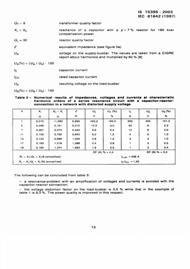
–* -L-,- n .,. .—--, ——, -— —.. ,.— —x z — ---l----- --- i----- - - - 1- - - - - - - - -. -L ----- -..:-.:-laDres - Numerlcal results OT Impedances, vonages arm currents a~ cnarawermuc
harmonic orders of a series resonance circuit with a capacitor-r-actor-
connection in a network with distorted supply voltage
h XT xc + XL z u~ u~ (=70) 1~ u~ us (%)
QQ Q v % A v YO
1 0,010 -1,000 0,990 400,0 100,0 233 404 101,0
5 0,048 0,161 0,212 12,0 3,0 33 9 2,3
7 0,067 0,373 0,443 9,6 2,4 13 8 2,0
11 0,106 -0,730 0,840 6,0 1,5 4 5 1,3
1“3 0,125 0,896 1,026 4,8 1,2 3 4 1,0
17 0,163 1,216 1,386 2,4 0,6 1 2 0,5
19 0,182 1,374 1,563 1,9 0,5 1 2 0,4
DF (A) 70 = 4,4 DF (B) Y. = 3,5
/+ = X~/~ = X~/8 (simplified) /c ~ff,= 236 A
RL = XL/QL = “XL/30(simplified) lcll~N = 1,02
The following can be concluded from table 3:
a resonance-problem with an amplification of voltages and currents is avoided with the
capacitor-reactor connection;
— the voltage distortion factor on the Ioad-busbar is 3,5 Y. while that in the example of
table 1 is 9,3 Y.. The power quality is improved in this respect.
13
8/12/2019 Is.15395.Industrial AC Networks Affected by Harmonic Application of Filters & Shunt Capacitors
http://slidepdf.com/reader/full/is15395industrial-ac-networks-affected-by-harmonic-application-of-filters 19/33
IS 15395:2003
[EC 61642(1997)
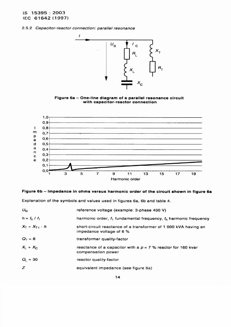
2.5.2 Capacitor-reactorc onnection:p arallelresonance
I
IHIB / c
XTRL
XLRT
-r
xc
Figure 6a - One-line diagram of a parallel resonance circuit
with capacitor-reactor connection
1, 0”
0,9”
I 0,8
; 0,7”
e 0,6
d 0,5a 0,4’n
c 0,3”
e 0,2
0,1 A
0,01 3
Figure 6b - Impedance in
Explanation of the symbols
5 7 9 11 13 15 17 19
Harmonic order
ohms versus harmonic order of the circuit shown in figure 6a
and values used in figures 6a, 6b and table 4.
UN reference voltage (example: 3-phase 400 V)
/?= f~/f, harmonic order, f, fundamental frequency, fh harmonic frequency
)(~=)(T,-h short-circuit reactance of a transformer of 1 000 kVA having an
impedance voltage of 6 ‘A
&=&3 transformer quality-factor
XL+xc reactance of a capacitor with a p = ‘7 0/0 reactor for 160 kvar
compensation power
Q~ = 30 reactor quality-factor
z equivalent impedance (see figure 6a)
14
8/12/2019 Is.15395.Industrial AC Networks Affected by Harmonic Application of Filters & Shunt Capacitors
http://slidepdf.com/reader/full/is15395industrial-ac-networks-affected-by-harmonic-application-of-filters 20/33
IS 15395:2003
IEC 61642 (1997)
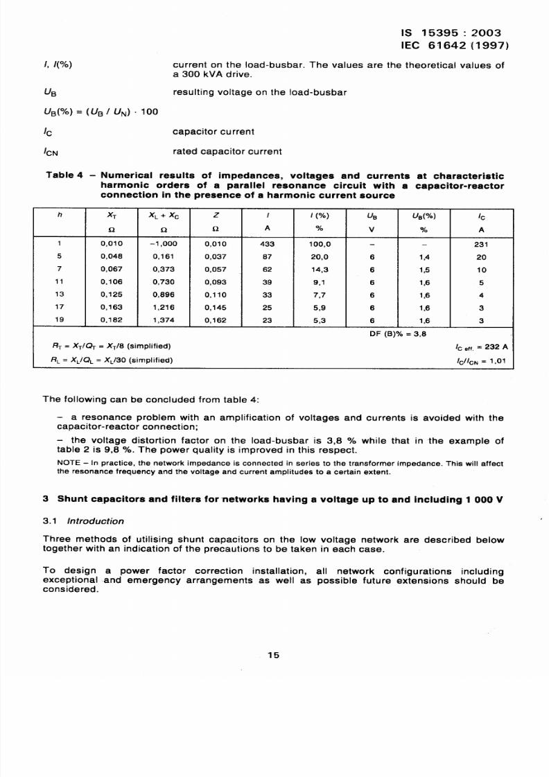
1, l( ) current on the Ioad-busbar. The values are the theoretical values of
a 300 kVA drive.
u~ resulting voltage on the Ioad-busbar
u~( )=(UB/uf J. 100
1~ capacitor current
lc~ rated capacitor current
Table 4 - Numerical results of impedances, voltages and currents at characteristic
harmonic orders of a parallel resonance circuit with a capacitor-reactor
connection in the presence of a harmonic current source
h XT XL + xc z I I (%) u~ u~(%) 1~
Q 0, Q A v A
1 0,010 –1,000 0,010 433 100,0 — 231
5 0,048 0,161 0,037 87 20,0 6 1,4 20
7 0,067 0,373 0,057 62 14,3 6 1,5 10
11 0,106 0,730 0,093 39 9,1 6 1,6 5
13 0,125 0,896 0,110 33 7,7 6 1,6 4
17 0,163 1,216 0,145 25 5,9 6 1,6 3
19 0,162 1,374 0,162 23 5,3 6 1,6 3
DF (B) = 3,8
R~= XT/~ = X~/6 (simplified) /c ~ff,= 232 A
RL= XL/QL= XL/30 (simplified) ICIICN= 1,01
The following can be concluded from table 4:
– a resonance problem with an amplification of voltages and currents is avoided with the
capacitor-reactor connection;
– the voltage distortion factor on the Ioad-busbar is 3,8 while that in -the example of
table 2 is 9,8 . The power quality is improved in this respect.
NOTE- In practice, the network impedance is connected in series to the transformer impedance. This will affectthe resonance frequency and the voltage and current amplitudes to a certain extent.
3 Shunt capacitors and filters for networks having a voltage up to and including 1000 V
3.1 h?troduction
Three methods of utilising shunt capacitors on the low voltage network are described below
together with an indication of the precautions to be taken in each case.
To design a power factor correction installation, all network configurations including
exceptional and emergency arrangements as well as possible future extensions should be
considered.
15
8/12/2019 Is.15395.Industrial AC Networks Affected by Harmonic Application of Filters & Shunt Capacitors
http://slidepdf.com/reader/full/is15395industrial-ac-networks-affected-by-harmonic-application-of-filters 21/33
~~ 153 35 : 2003
IEC 61642 (199~;
3.2 Shurrt capacitors
This type of power factor correction installation can be used when it is not necessary to take
measures to avoid resonance problems or to reduce harmonics. This is generally the case
when the resonant frequency given by the network inductance and the capacitance of the
power factor correction installation is relatively high and the harmonic content of the network(i.e. bus voltage and harmonic currents generated by the loads) is very low.
It should however be understood that the total resulting capacitance of all power factor
correction installations connected to the low voltage side of one distribution transformer
determines the possibility of a harmonic resonance problem. Avoiding such problems when the
power factor correction installation is alread_y in service can be more difficult and costly than at
the original installation time as it is often not possible to re-use existing capacitors, frames, etc.
3.3 Detuned filter
As shown in 2.5, an effective way to prevent harmonic resonance problems from a technical as
well as an economical point of view is to connect a reactor in series with each phase of eachcapacitor step of the power factor correction installation.
This type of power factor correction installation (detuned filter) also gives the advantage of
reducing the harmonic voltages in the network by absorbing part of the harmonic currents with
an order higher than the tuning frequency of the reactor-capacitor arrangement.
The choice of the tuning frequency of the reactor-capacitor arrangement depends on the
magnitudes and frequencies of the harmonic currents circulated in the network, and on the
signal frequency of a ripple control installation if any (see 3.6).
Typically, reactors cannot be added to existing capacitors to make a detuned filter as theinstalled capacitors may not be rated for the additional voltage andlor current caused by the
added series reactor.
Normally, a power factor correction installation having series reactors shall not be mixed with
an equipment without series reactor. Care should also be taken when a detuned filter is
extended by equipment having a different tuning frequency. In both cases problems can occur
due to unequal sharing of the harmonic load and possible overloading of one filter or part of it.
3.4 Tuned filter
To keep the harmonic voltages in the network to an acceptable level, a tuned filter may have to
be considered as mentioned in 1.4.1. The filters act as a load on the harmonic generator
absorbing the harmonic currents and thus reducing the harmonic voltage increases. When
assessing the requirements of the tuned filter it is important to consider the complete network
system.
To design a tuned filter it is necessary to know the harmonic impedance values of the network,
especially the impedance of the distribution transformer as well as the frequency spectrum of
the harmonic source(s) and the harmonic voltages in the high voltage network.
A tuned filter comprises one or more tuned filter units (series connection of reactor and
capacitor on each phase) each tuned to give a relatively low impedance at the considered
harmonic frequency compared to the impedance of the network at the same frequency.Harmonic currents are thus mainly absorbed by this filter. At the network frequency the filter
acts as a capacitor providing power factor correction.
16
8/12/2019 Is.15395.Industrial AC Networks Affected by Harmonic Application of Filters & Shunt Capacitors
http://slidepdf.com/reader/full/is15395industrial-ac-networks-affected-by-harmonic-application-of-filters 22/33
Is 15395:2003
IEC 61642 (1997)
Generally, tuned filter units need to be desigmed for the odd harmonic orders except multiples
of 3, i.e. 5, 7, 11, 13, 17, 19, etc. in increasing order. Usually, in low voltage installations the
third harmonic needs not be considered as it only appears between phase and neutral and
most of the power factor correction installations are connected between phases (no connection
to the neutral). However, in the case of unbalanced load, .a third harmonic filter unit may be
considered.
Normally, the following are valid:
the reactive power rating at network frequency of each tuned filter unit decreases with
increasing -harmonic order;
all tuned filter units of a filter are switched together. If, however, it is necessary to switch
the tuned filter units independently, they should be switched on in ascending order 5, 7, 11,
etc. and switched off in the reverse order;
– the rated tuning frequency of a filter unit is generally chosen slightly lower than the
harmonic frequency. Thus, the impedance of the tuned filter unit is inductive at the harmonic
frequency.
Care should be taken to fit tuned filters to individual items of equipment connected to the low
voltage side of the same distribution transformer in order to avoid problems. Parallel connected
filter units for one harmonic order will not have exactly the same resonance frequency due to
the tolerances of the components causing problems, for example, due to unequal sharing of
the harmonic load and/or to parallel resonances between tuned filters. In such cases itcould
be useful to use additional contacts to connect together the points between reactors and
capacitors of each phase of the filter units for the same harmonic order which are in service.
3.5 Components selection
A low voltage power factor correction installation
consists of some or all of the following components:
– capacitors;
– reactors (for example in case of filters);
– contractors and/or circuit-breakers;
is usually installed indoors and normally
– short-circuit protection (fuses or circuit=breaker).
The determination of ratings for these components is usually based on the calculated stresses
during worst service conditions. Harmonic currents generated by the electrical loads and any
harmonic current or voltage existing on the network have to be considered when designing
power factor correction installation and/or filter.
It should be checked that the manufacturing tolerances, the influence of temperature and
ageing, the operation of internal or external fuses if any, the possible non-linearity of the filter
components as well as the variation of the network frequency will not cause unacceptable
repercussions on the function of the filter.
3.5.1 Capacitors
The capacitor units or bank are the fundamental part in each power factor correction
installation and/or filter. A thorough study should therefore be performed in order to obtain
optimal capacitor design.
The capacitor current consists of fundamental and harmonic frequency components. As the
magnitude of harmonic components may be very high, especially in a tuned filter, it is
necessary to take them into account when defining rated values of the capacitors.
For filters the voltage increase on the capacitor caused by the series connection of the reactor
should be considered.
17
8/12/2019 Is.15395.Industrial AC Networks Affected by Harmonic Application of Filters & Shunt Capacitors
http://slidepdf.com/reader/full/is15395industrial-ac-networks-affected-by-harmonic-application-of-filters 23/33
Is 15395:2003
IEC 61642(1997)
3.5.2 Reactors
The reactor current consists of fundamental and harrjnonic frequency components. As the
magnitude of harmonic components may be very high, especially in a tuned filter, it is
necessary to take them into “account when defining rated values of the reactors.
The reactor shall be designed for the thermal load due to the maximum fundamental and
harmonic currents.
Manufacturing tolerance for the inductance of the reactor is to be taken into account in filter
design. A value of *3 Y. is acceptable for most filter applications.
The reactor shall be able to withstand the short-circuit current which can occur during fault
conditions as well as the switching current and voltage.
The inductance value of the reactor shall not vary by more than 5 Y. from rated current to the
highest loading given by the peak value of the current or voltage (induction caused by thearithmetic sum of the maximum fundamental and harmonic currents or voltages).
When using reactors with an iron core (which is the normal case in low voltage filters), care
should be taken to avoid saturation problems (important change of inductance value, ferro-
resonance occurring during switching operations and leading to overloading of components,
etc).
The losses of the reactors should be considered.
3.5.3 Contractors andlor circuit-breakers
T-he switching of power factor correction installations requires some special features of the
switching device. The following aspects shall be therefore considered:
– the contactor and circuit-breaker shall be restrike-free and adapted for capacitors;
– the ‘rated voltage of the contactor and circuit-breaker shall be equal to or higher than the
maximum network voltage with the power factor correction installation and/or filter in
service;
– the contactor and circuit-breaker shall be designed for continuous current (including
harmonics) which can pass the power factor correction installation and)or filter at maximum
source voltage, maximum frequency and extreme tolerances of the components, especially
capacitor and reactor;
– the interrupting rating of circuit-breaker shall be equal to or greater than the short-circuit
current which can occur on the power factor correction installation and/o~ filter side;
– the contactor and circuit-breaker shall have sufficient short-time current rating to
withstand both system short-circuit faults and inrush currents associated with energizing;
– the type of the contactor and circuit-breaker shall be selected with respect to the
expected frequency of switching operations.
3.5.4 Short-circuit protection (fuses)
The Fated voltage of the short-circuit protection shall be equal to or greater than the maximum
network voltage with the power factor correction installation and/or filter in service.
The short-circuit protection shall be designed for continuous current (including harmonics)
which can pass the power factor correction installation and/or filter at maximum source voltage,
maximum frequency and extreme tolerances of the components, especially capacitor and
reactor.
18
8/12/2019 Is.15395.Industrial AC Networks Affected by Harmonic Application of Filters & Shunt Capacitors
http://slidepdf.com/reader/full/is15395industrial-ac-networks-affected-by-harmonic-application-of-filters 24/33
IS 15395:2003
IEC 61642 (1997)
The interrupting rating shall be equal to -or greater than the short-circuit current which can
occur on the power factor correction installation and/or filter.
The short-circuit protection shall have sufficient short-time current rating to withstand both
system short-circuit faults and inrush currents associated with energizing.
3.6 Disturbance of ripple control installations by shunt capacitors and filters
The influence of the power factor correction installations and filters on the ripple control
installation is described below, for each method of use of shunt capacitors.
3.6.1 Shunt capacitors
For audio frequency signals injected into the high voltage network by a ripple control
installation the capacitance of the power factor correction installation forms a series resonant
circuit with the inductance of the distribution transformer. W-hen the resonance frequency of
this circuit is the same as or close to the signal frequency problems could occur. The voltage of
the signal in the low voltage network may be increased to an unacceptable level, and theimpedance, at this frequency, in the high voltage network may be reduced leading to additional
loading of the ripple control signal generator. When the resonance frequency is much lower
than that of the ripple control signal the voltage of this signal may be reduced to an
unacceptable level.
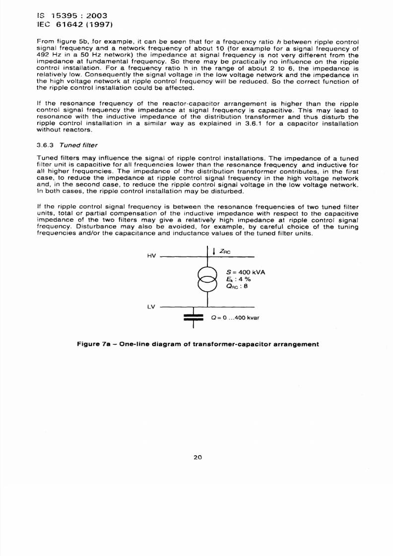
An example of this is shown in figures 7b and 7C for a transformer-capacitor arrangement
corresponding to figure 7a for four different ripple control signal frequencies. Close to the
resonance frequency the impedance of the arrangement is much lower than the nominal load
impedance which may lead to an overloading of the ripple control generator. On the other
hand, the ripple control signal voltage can be increased or reduced to levels which may disturb
the ripple control receivers.
Explanation of the symbols used in figures 7a, 7b and 7c:
‘RC impedance at ripple control frequency of transformer-capacitor arrangement
z, nominal load impedance at network frequency
s transformer rating
k impedance voltage of the transformer in per cent
Q shunt capacitor rating
‘RC ripple control signal voltage in the low voltage network
‘RCO ripple control signal voltage when no shunt capacitor is connected
‘RC ripple control signal frequency
‘RC quality factor of the transformer at ripple control signal frequency
3.6.2 Detuned filter
Reactors connected in series with the capacitors of power factor correction installations
prevent such disturbances of the ripple control installation if the resonance frequency of the
reactor-capacitor arrangement is lower than and far enough from the ripple control signal
frequency.
19
8/12/2019 Is.15395.Industrial AC Networks Affected by Harmonic Application of Filters & Shunt Capacitors
http://slidepdf.com/reader/full/is15395industrial-ac-networks-affected-by-harmonic-application-of-filters 25/33
Is “/5395 :2003
IEC 61642(1997)
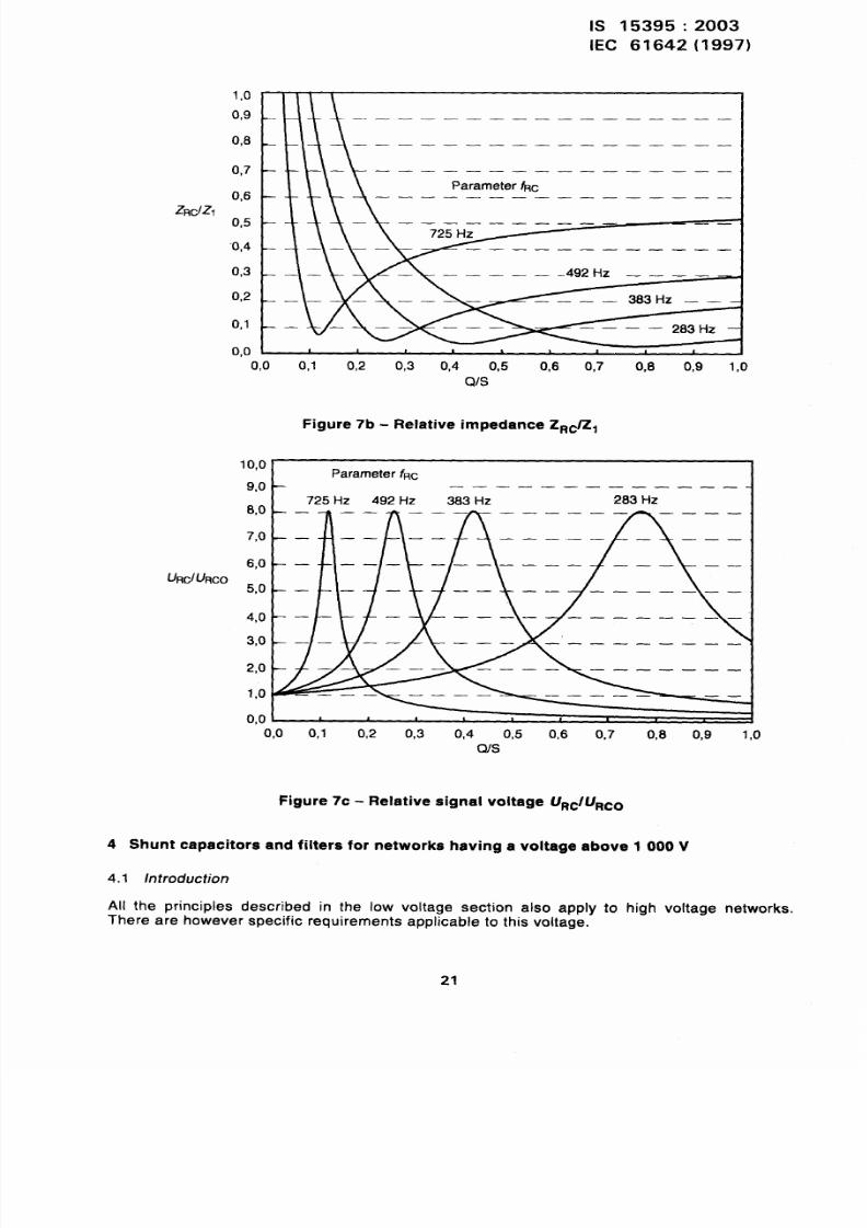
From figure 5b, for example, it can be seen that for a frequency ratio h between ripple control
signal frequency and a network frequency of about 10 (for example for a signal frequency of
492 Hz in a 50 Hz network) the impedance at signal frequency is not very different from the
impedance at fundamental frequency. So there may be practically no influence on the ripplecontrol installation. For a frequency ratio h in the range of about 2 to 6, the impedance is
relatively low. Consequently the signal voltage in the low voltage network and the impedance in
the high voltage network at ripple control frequency will be reduced. So the correct function ofthe ripple control installation could be affected.
If the resonance frequency of the reactor-capacitor arrangement is higher than the ripple
control signal frequency the impedance at signal frequency is capacitive. This may lead to
resonance with the inductive impedance of the distribution transformer and thus disturb the
ripple control installation in a similar way as explained in 3.6.1 for a capacitor installation
without reactors.
3.6.3 Tuned filter
Tuned filters may influence the signal of ripple control installations. The impedance of a tuned
filter unit is capacitive for all frequencies lower than the resonance frequency and inductive forall higher frequencies. The impedance of the distribution transformer contributes, in the first
case, to reduce the impedance at ripple control signal frequency in the high voltage network
and, in the second case, to reduce the ripple control signal voltage in the low voltage network.
In both cases, the ripple control installation may be disturbed.
If the ripple control signal frequency is between the resonance frequencies of two tuned filter
units, total or partial compensation of the inductive impedance with respect to the capacitive
impedance of the two filters may give a relatively high impedance at ripple control signal
frequency. Disturbance may also be avoided, for example, by careful choice of the tuning
frequencies and/or the capacitance and inductance values of the tuned filter units.
= 400 kVA
&:4
Qm :8
I
-r
(?= O ...400 kvar
Figure 7a - One-line diagram of transformer-capacitor arrangement
20
8/12/2019 Is.15395.Industrial AC Networks Affected by Harmonic Application of Filters & Shunt Capacitors
http://slidepdf.com/reader/full/is15395industrial-ac-networks-affected-by-harmonic-application-of-filters 26/33
IS 15395:2003
[EC 61642 (1997)
1,0
0,9
0,8
0,7
0,6
0,5
0,4
0,3
0,2
0,1
0.0
11~-———————————_——————
rafm?tt?rRc— —— —— —— —— —— —— __ _
— —— —— —— __ __ ——725 Hz
— —— — —— —— —— —— —. ——
— — — —— —— — .492Hz ————
i–~– – – 383H’ – –_
——— —— —— 283 HZ --
I I , , , , , , I
0,0 0.1 0,2 0,3 0,4 0,5 0,6 0,7 0,8 0,9 1,0QIS
Figure 7b - Relative impedance ZRc Z1
10,0parameter fRc
9.0 —— —— —— __ __ __ _.
8,0
F,0 —
6,0 —
UBc/URco5,0 —
4,0
3,0
2,0
1,0
0,0
283 HZ
0,0 0,1 0,2 0,3 0,4 0,5 0,6 0,7 0,8 0,9 1,(JQ/s
Figure 7C - Relative signal voltage URc/URco
4 Shunt capacitors and filters for networks having a voltage above 1000 V
4.1 Introduction
All the principles described in the low voltage section also apply to high voltage networks.
There are however specific requirements applicable to this voltage.
21
8/12/2019 Is.15395.Industrial AC Networks Affected by Harmonic Application of Filters & Shunt Capacitors
http://slidepdf.com/reader/full/is15395industrial-ac-networks-affected-by-harmonic-application-of-filters 27/33
1s 15395:2003
EC 61642(1997)
4.2 Specific requirements
The system configuration and, consequently, the short-circuit power are generally variable in
high voltage networks. Variations shall be considered for all conditions when designing
equipment.
High voltage power factor correction equipment may be installed indoors or outdoors, thefollowing having an effect on the design:
– adverse atmospheric conditions, pollution, etc, requiring increased creepage and
clearance distances;
climatic conditions;
mechanical stress, seismic forces;
solar radiation.
Harmonics generated by the electrical loads and any harmonics existing on the network have to
be considered when designing power factor correction installations.
4.3 Choice of power factor correction installation
A network analysis should be carried out to determine the most appropriate equipment to be
installed. Whenever possible existing harmonic distortion should be measured although the
interpretation of the results should be considered with care.
The network analysis should take into account the following points:
– all network configurations should be considered, including exceptional and emergency
arrangements as well as possible future extensions. Special attention shall be paid to
electrical machines (generators, synchronous compensators), cable capacitance, line
impedance, etc.;
– harmonic generation (distortion ratios) obtained in all the different working configurations.
This should take into account the existing harmonic sources on the system. Measurements
and/or calculation of the harmonic currents is necessary. Figures deduced from harmonic
voltage distortion alone are not accurate as harmonics -are generated by current not by
voltage sources. When the user plans to install a filter on a system which is not separated
from the utilities network by an interposing transformer or another significant impedance,
the effect of all other shunt capacitors and filters on the network have to be considered;
- existing power factor correction installations, detuned and tuned filters;
- the influence of power factor correction installations and filters on ripple control
installations shall be investigated to ensure that system malfunction does not occur.
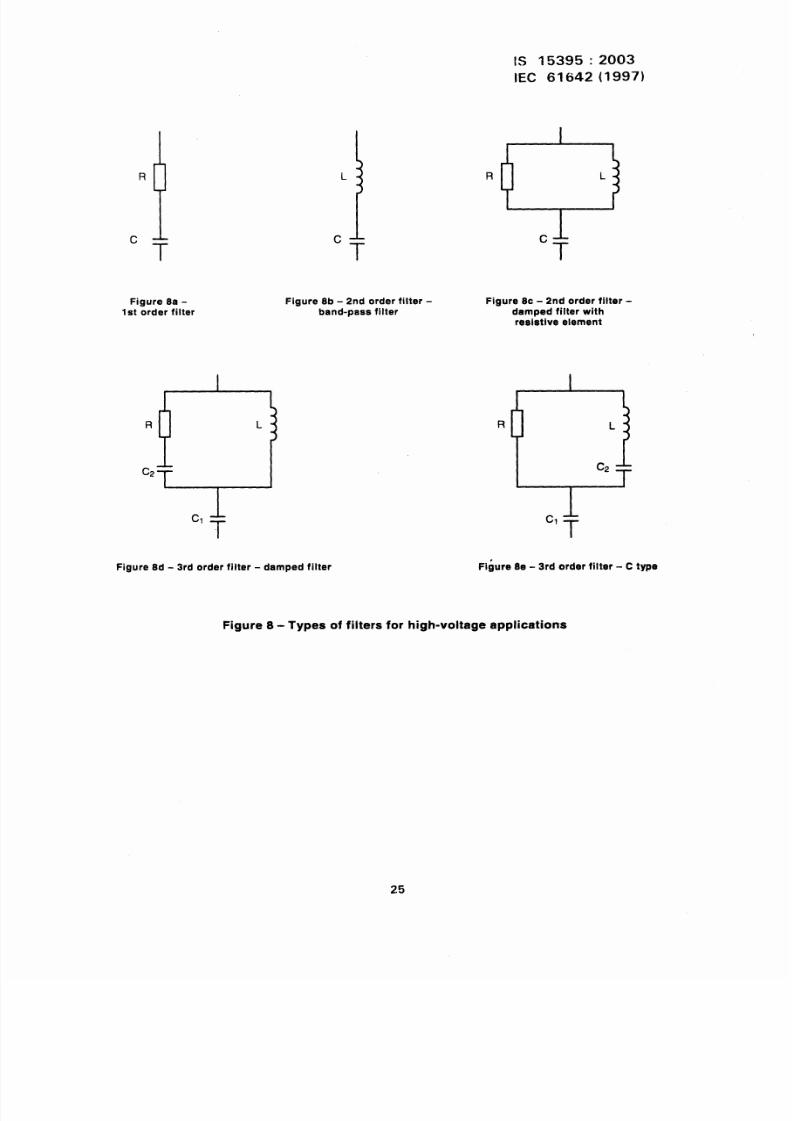
4.4 Type of filters
Filter systems of Ist, 2nd, and 3rd order are usually considered (see figures 8a, 8b, 8c, 8d
and 8e). The order of a filter can be determined by the number of reacti~e components in the
circuit. Damping circuits may be considered due to technical and/or economical reasons. If a
damped filter is used, loss evaluation is necessary. The most frequently used harmonic orders
for filter tuning are 5, 7, 11, 13, 17, 19, 23, 25.
When a harmonic distortion limit has to be guaranteed, account shall be taken of capacitor and
reactor mantifacturing tolerances. With filters it is not always possible to maintain both the
harmonic distortion and the power factor within given limits.
22
8/12/2019 Is.15395.Industrial AC Networks Affected by Harmonic Application of Filters & Shunt Capacitors
http://slidepdf.com/reader/full/is15395industrial-ac-networks-affected-by-harmonic-application-of-filters 28/33
IS 15395:2003
IEC 61642 (1997)
4.5 Filter components selection
A high voltage filter normally consists of the following components:
— circuit-breaker;
– capacitors;– reactors;
– resistors;
– protection equipment.
The determination of ratings for these components is usually based on the calculated stresses
during worst service conditions. Harmonic currents generated by the electrical loads and any
harmonic current or voltage existing an the network have to be considered when designing
power factor correction or filter installation.
It should be checked that the manufacturing tolerances, the influence of temperature andageing, the operation of internal or external fuses if any, the possible non-linearity of the filter
components as well as the variations of the network frequency will not unacceptably influence
the function of the filter.
4.5.1 Circuit-breaker
The switching of filters requires some special features of the switching device. The following
aspects shall therefore be considered:
– the circuit-breaker shall be restrike-free;
the rated voltage of the circuit-breaker shall be equal to or higher than the maximum
network voltage with the filter in service;
— the circuit-breaker shall be designed for continuous current which can pass the filter at
maximum source voltage, maximum frequency and capacitance deviation;
— the interrupting capacity shall be equal to or greater than the short-circuit current which
can occur on the filter side of the circuit-breaker;
the circuit-breaker shall have sufficient short-time current rating to withstand both system
short-circuit faults and inrush currents associated with energizing;
— the type of the circuit-breaker shall be selected with respect to the expected frequency of
switching operations.
4.5.2 Capacitors
The capacitor bank is the fundamental part in each filter equipment. A thorough study should
therefore be performed in order to obtain optimum capacitor design.
The filter current consists of fundamental and harmonic frequency components. As the
magnitude of harmonic components may be very high, it is necessary to take them into account
when defining rated data of the capacitors.
The following definitions and designing criteria are specific to filter capacitors:
rated capacitor voltage, rated capacitor current and tolerances: see the relevant
capacitor standard;
the ratings of a capacitor should make allowances for element failure or fuse operation
and should co-ordinate with filter protection. During service, if the capacitance change
exceeds the acceptable range for the filter, the filter should be disconnected from the
system.
8/12/2019 Is.15395.Industrial AC Networks Affected by Harmonic Application of Filters & Shunt Capacitors
http://slidepdf.com/reader/full/is15395industrial-ac-networks-affected-by-harmonic-application-of-filters 29/33
IS 15395:2003
IEC 61642(1997)
4.5.3 Reactors
When selecting filter reactors, the following aspects shall be considered:
– thermal load due to the maximum fundamental and harmonic currents;
– manufacturing tolerance of inductance: for most filter applications *3 O/. is acceptable.In special cases adjustment taps -may be required;
short-circuit current which can occur during fault conditions;
- linear characteristic within the current and frequency ranges;
- the effects of eddy current losses in adjacent metallic parts, for example equipment
frame, earthing system and building structural steel.
4.5.4 Resistors
When selecting filter resistors, the following aspects should be considered:
– total r.m.s. current through the resistor;
inductance of the resistor;
manufacturing tolerance and temperature coefficient of the resistance.
4.5.5 Relay protection
The protection system normally consists of:
– harmonic overload protection;
- overcurrent protection;
earth fault protection;
undervoltage protection;
- unbalance protection of the.capacitor bank.
4.6 Disturbance of ripple control installations by shunt capacitors and filters
The influence of power factor correction installations and filters on ripple control installations
shall be investigated to ensure that system malfunction does not occur.
The tuning frequencies of the power factor correction installation should not be the same as the
ripple control signal frequency, but far enough from it. Due to the inductive impedance of the
line between the injection point of the ripple control installation and the power factor correctioninstallation, the ripple control signal voltage may be reduced or increased. It will be reduced if
the impedance of the power factor correction installation is inductive at ripple control signal
frequency and increased if it is capacitive. It should be ensured that the influence on the ripple
control signal voltage is within acceptabi.e limits, referring to the general requirements of 3.6.
24
8/12/2019 Is.15395.Industrial AC Networks Affected by Harmonic Application of Filters & Shunt Capacitors
http://slidepdf.com/reader/full/is15395industrial-ac-networks-affected-by-harmonic-application-of-filters 30/33
R
c
Figure 8a -1st order filtsr
I
R L
Figure 8b - 2nd order filter -
band-pass filter
cl LT
Figure 8d - 3rd order filter - damped filter
IS 15395:2003
IEC 61642 (1997)
R
oFigure 8C- 2nd order filter -
damped filter withraaistive element
R
Figure Se - 3rd order filter - C type
Figure 8- Types of filters for high-voltage application
25
8/12/2019 Is.15395.Industrial AC Networks Affected by Harmonic Application of Filters & Shunt Capacitors
http://slidepdf.com/reader/full/is15395industrial-ac-networks-affected-by-harmonic-application-of-filters 31/33
IS 15395:2003
IEC 61642(1997)
Annex A
(informative)
Bibliography
[1]
[2]
[3]
[4]
[5]
[6]
[7]
[8]
IEC 60110:1973, Recommendation for capacitors for inductive heat generating p/ants
operating at frequencies between 40 Hz and 24000 Hz
IEC 60143:1992, Series capacitors for power systems
IEC 60358:1990, Coupling capacitors and capacitor dividers
IEC 601071: Power electronic capacitors
IEC 60252:1993, AC motor capacitors
IEC 61048:1991, Capacitors for use in tubu/ar fluorescent and other discharge /amp
circuits. Genera/ and safety requirements
IEC 61049:1991, Capacitors for use in tubular fluorescent and other discharge lamp
circuits. Performance requirements
Harmonics characteristic parameters, methods of study, estimates of existing va/ues in
network, CIG RE, W G36-05, E/ectra no. 77
IEC 60050(421):1990, /nternafiona/ E/ectrotechnica/ Vocabulary (/EV) – Chapter 421: Power
transformers and reactors
IEC 60050(436):1990, /nternationa/ E/ectrotechnica/ Vocabulary (/EV) – Chapter 436: Power
capacitors
IEC 60056:1987, High-vo/tage a/ternating-current circuit-breakers
IEC 60146: Semiconductor convertors
IEC 60242:1967, Standard frequencies for centralized network contro/ insta// ions
IEC 60255-6:1988, E/ectrica/ re/ays - Part 6: Measuring relays and protection equipment
IEC 60265-1:1983, High-voltage switches – Part 1: High-vo/tage switches for rated vo/tages
above 7 kV and /ess tfian 52 k-V
IEC 60265-2:1988, High-vo/tage
52 kV and above
IEC 60269: Low-vo/tage fuses
IEC 60282: High-vo/tage fuses
IEC 60289:1988, Reactors
switches – Part 2: High-voltage switches for rated voltages of
IEC 60291:1969, Fuse definitions
IEC 60549:1976, High-vo/tage fuses for the externa/ protection of shunt power capacitors
26
8/12/2019 Is.15395.Industrial AC Networks Affected by Harmonic Application of Filters & Shunt Capacitors
http://slidepdf.com/reader/full/is15395industrial-ac-networks-affected-by-harmonic-application-of-filters 32/33
IS 15395:2003
IEC 61642 (1997)
IEC 60831-1:1996, Shunt power capacitors of the se/f-hea/ing type for a.c. systems having a
rated vo/tage up to and including 1 000 V – Part 1: General – Performance, testing and rating –
Safety requirements – Guide for installation and operation
IEC 60871-1:1987, Shunt capacitors for a.c. power systems having a rated vo/tage above
660 V – Part 1: Genera/ – Performance, testing and rating - Safety requirements - Guide forinstallation and operation
IEC 60871-2:1987, Shunt capacitors for a.c. power systems having a rated voltage above
660 V – Part 2: Endurance testing
IEC 60931-1:1996, Shunt power capacitors of the non-se/f-hea/ing type for a.c. systems having
a rated voltage up to and including 1 000 V – Part 1: General - Performance, testing and
rating-Safety requirements - Guide for installation and operation
IEC 61000-2-2:1990, Electromagnetic compatibility (EMC) - Part 2: Environment - Section 2:
Compatibility levels for low-frequency conducted disturbances and signaling in public low-
vo/tage power supp/y systems
27
8/12/2019 Is.15395.Industrial AC Networks Affected by Harmonic Application of Filters & Shunt Capacitors
http://slidepdf.com/reader/full/is15395industrial-ac-networks-affected-by-harmonic-application-of-filters 33/33
ureau of Indian Standards
BIS is a statutory institution established under the Bureau oj_ Indian Standards Act 1986 to promote
harmonious development of the activities of standardization, marking and quality certification of goods and
attending to connected matters in the country,
Copyright
BIShasthe copyright of all its publications. No part of these publications may be reproduced inany form without
the prior-permission in writing of BIS. This does not preclude the free use, in the course of implementing the
standard, of necessary details, such as symbols and sizes, type or grade designations. Enquiries relating to
copyright be addressed to the Director Publications , BIS.
Review of Indian Standards
Amendments are issued to standards as the need arises on the basis of comments. Standards are also reviewed
periodically; a standard along with amendments is reaffirmed when such review indicates that no changes are
needed; if the review indicates that changes are needed, it is taken up for revision. Users of Indian Standards
should ascertain that they are in possession of the latest amendments or edition by referring to the latest issueof ‘BIS Catalogue’ and ‘Standards : Monthly Additions’.
This Indian Standard has been developed from Doc : No. ET29 5225 .
mendments Issued Since Publication
Amend No. Date of Issue Text Affected
BUREAU OF INDIAN STANDARDS
Headquarters:
Manak Bhavan, 9 Bahadur Shah Zafar Marg, New Delhi 110002 Telegrams: Manaksanstha
Telephones: 23230131,23233375,2323 9402 Common to all offices
Regional Offices : Telephone
Central : Manak Bhawm, 9 Bahadur Shah Zafar Marg
{
23237617
NEW DELHI 110002 23233841
Eastern : l/14C. I. T. Scheme VI1M, V. I. P. Road, Kankurgaclii
{
23378499,23378561
KOLKATA700 054 23378626,23379120
Northern: SCO 335-336, Sector 34-A, CHANDIGARH 160022
{
603843
609285
Southern :C. 1.T. Campus, IVCross Road, CHENNA1 600113
{
22541216,22541442
22542519,22542315
Western : Manakalaya, E9 MlDC, Marol, Andheri East
{
28329295,28327858
MUMBAI 400093 28327891,28327892
Branches : AHMEDABAD. BANGALORE. BHOPAL. BHUBANESHWAR. COIMBATORE.
FARIDABAD. GHAZIABAD. GUWAHATI. HYDER4BAD. JAIPUR. KANPUR.