IS0211E Print pdf -...
28
MG2000 Speedometer for use with SmartCraft™ Tachometer IS0211 rev. E ecr#6395 08/2006 Owner’s Manual
-
Upload
nguyenthuy -
Category
Documents
-
view
241 -
download
1
Transcript of IS0211E Print pdf -...
MG2000 Speedometerfor use with SmartCraft™ Tachometer
IS0211 rev. E ecr#6395 08/2006
Owner’s Manual

4/5/05Changes 12/21

IndexDescription
Available Functions for display page 1
Default Screens page 1
Figure 1 page 2
Description page 2
Normal Mode page 3
Contrast and Lighting page 3
Displayed Functions page 4
Figure 2 - Select Mode page 6
Figure 3 - LCD Display Screens page 7
Fuel Functions page 8
Fuel Level Sender page 8
Manual Settings page 8
COG (Course Over Ground) page 9
Edit Mode page 11
Select “Default Screen” page 12
Reset “Trip Log” page 12
Organize User Screens page 12
Organize Screen 1 page 13
Select “Adjust Clock Offset” page 14
Select “Enable Display Screens” page 14
Select “Set Clock Type” page 14
Select “Set GPS COG Display” page 15
Select “Self Test” page 15
Select “Software Id And Revision” page 16
Alarm Mode page 17
Figure 4 - Alarm Screen page 17
Low Fuel - Low Oil page 17
Harness - HN0403 page 19
Harness - HN0407 page 21
2 inch Gauge connection page 22

This page left blank intentionally.

FARIA® MG2000 Speedometer ManualThe FARIA® MG2000 speedometer combines the features of a speedometer and several digital instruments into one unit:
• The MG2000 speedometer pointer is analog in appearance but is driven by a stepper motor for digital accuracy.
• The high resolution LCD screen displays information for many other functions and the various “screens” can be configured as the user wishes. As received, the screens are configured as shown in Fig. 1.
The MG2000 speedometer receives digital data via the Faria Serial Bus from the MG2000 tachometer. An analog input is provided for a sensor for air temperature.
The Faria MG2000 speedometer will turn on when the ignition key is turned on and will turn off when the ignition key is turned off.
The unit will power up showing the default screen selected by the user.
Available functions for display in MG2000 speedometer screensThe functions listed below can be displayed in the user configured screens. All of the functions may not be available in your installation. If a function is selected for display and that function does not appear on the screen, the function does not exist in this installation.
1. GPS Clock2. Fuel Level (bar graph)3. Fuel Left4. GPS Heading5. GPS Lat and Long6. GPS Speed7. Air Temperature (Analog input to
MG2000 Speedometer from air temp sender)
8. Sea Temperature9. Speed10. Inst Econ(omy)11. Avg Econ(omy)12. Estimated Range13. Avg Fuel Flow14. Fuel Used15. Trip miles16. Steer Angle
Default Screen 1
Other default screens:
Page 1

Note: The GPS data shown on the Faria® MG2000 is for reference only and is not meant to be used as a navigational device.
Figure 1
DescriptionThe instrument has three push buttons; “Down”, M “Mode”, and “Up”; that control the functions available.
The M “Mode” button is used to change the function of the LCD display and to access submenus and adjustable settings.
The “Down” and “Up” buttons are used to modify the settings.
In the normal operation mode, pressing the M “Mode” button and then pressing “Down” or “Up” causes the display to cycle between the available screens.
Press the M “Mode” button to exit the “Screen Selection” mode and return to the normal mode or if no button is pushed for 4 seconds the current screen will stay selected and the unit will automatically return to the normal mode. (see Figure 2).
From the “Normal” mode, press the M “Mode” and “Up” buttons to change to the
Page 2

“Edit” menus (See Figure 3).
When “Edit” menus have been selected, press the M “Mode” button for the instrument to return to normal mode.
Press the “Down” or “Up” to cycle between the available “Edit” functions.
Press and hold the “Down” and “Up” buttons for two (2) seconds to select an “Edit” function to change.
Within each “Editing” function the “Down” or “Up” buttons select settings or sub-functions. Follow the instructions in the “Edit” mode section of this manual to save the new settings after you select / adjust them.
Normal ModeWhen the MG2000 speedometer is turned on, the unit enters “Self Test” mode. The screen will display “Self Test Faria MG2000 SW ID + Rev. PGFXXXXX Date” for 12 seconds.
The backlights and warning lights will
flash three times. When this is complete, the user selected “Default” screen will appear.
The information below applies to the MG2000 speedometer as received with no user changes to the screen selections.
Contrast and LightingIn the “Normal“ operating mode the instrument display contrast and display mode can be adjusted by pressing the “Down” and “Up” buttons.
With the display in “Positive” mode, black on white, pressing the “Down” button decreases the contrast. Pressing the “Up” button increases contrast.
Continuing to press the “Up” button causes the display to reverse to the “Negative” mode, white on black. The contrast in this mode is controlled the same way as the “Positive” mode.
To return to “Positive” mode, continue to press the “Down” button until the display reverses.
To adjust the lighting intensity of all of the instruments in the system, press and hold both the “Down” and “Up” buttons for 2 seconds. The lighting intensity may now be adjusted by using the “Down” or “Up” buttons.
Return to the “Normal” mode by pressing and holding both the “Down” and “Up” buttons for 2 seconds. Page 3

MG2000 speedometer displayed functionsDefault Screen “1”
ClockDisplays time received from the GPS NMEA0183 signal (if installed and connected). The display will be in 12 or 24 hour format based on the “Set Clock Type” setting selected in the “Edit” mode.
Fuel LevelDisplays fuel level in Tank 1 as received from the MG2000 SmartCraft tachometer from the engine ECU. This is fuel level sender information. The fuel level sender should be calibrated as described in the Faria SmartCraft MG2000 tachometer manual.
SpeedDisplays current speed in water from the installed pitot tube and/or paddle wheel as received from the MG2000 SmartCraft tachometer from the engine ECU. Default Screen “2”
ClockDisplays time received from the GPS NMEA0183 signal (if installed and connected). The display will be in 12 or 24 hour format based on the “Set
Clock Type” setting selected in the “Edit” mode.
Fuel LeftDisplays the calculated amount of fuel left in Tank 1. This display shows the calculated amount of fuel remaining based on the fuel information entered by the operator minus the fuel used as calculated from the “Gal Per Hour” data received from the engine ECU.
For this function to provide correct information the operator MUST set “Fuel Tank Size”, “Fuel Tank Full” or “Amount of Fuel” in the MG2000 tachometer edit menu. This display is NOT information from the fuel level sender and must be used carefully.
SpeedDisplays current speed in water from the installed pitot tube and/or paddle wheel as received from the MG2000 SmartCraft tachometer from the engine ECU.
Default Screen “3”
COG (Course Over Ground)
Displays the GPS heading received from the GPS NMEA0183 signal (if installed and connected). The display will be in “True” or “Mag” heading based on the “set GPS COG display” setting selected in the “Edit” mode.
If magnetic bearing is not available from the GPS unit, the operator will be unable to select “Mag” in the “Set GPS COG Display” function. In addition, the screen display will change to:
Page 4

The display will continuously flash at a slow rate to ensure that the operator is aware that the displayed COG is being presented in relation to TRUE NORTH not magnetic north!
Lat LongDisplays the GPS Latitude and Longitude of the current location received from the GPS NMEA0183 signal (if installed and connected).
GPS SpeedDisplays GPS (SOG) speed received from the GPS NMEA0183 signal (if installed and connected).
Note: The GPS data shown on the Faria® MG2000™ is for reference only and is not meant to be used as a navigational device.
Default Screen “4”
Air TempAnalog input. Displays current air temperature (if sensor is installed and connected), (displays -4.0˚ F if the air temperature sensor is not installed or connected).
Sea TempDisplays current sea or lake water temperature as received from the MG2000 SmartCraft tachometer from the engine ECU.
SpeedDisplays current speed in water from the installed pitot tube and/or paddle wheel as received from the MG2000 SmartCraft tachometer from the engine ECU.
Default Screen “5”
Inst EconDisplays calculated instantaneous fuel economy based on current Gal Per Hour and vehicle speed as received from the MG2000 SmartCraft tachometer from the engine ECU.
Avg EconDisplays calculated average fuel economy for this period of continuous operation. This function is reset to zero when the engine is shut off.
Est. RangeDisplays the distance that can be traveled with the displayed amount of Fuel Left and the current fuel rate (GPH) being used by the engine as received from the MG2000 SmartCraft tachometer from the engine ECU. “Fuel Tank Size”, “Fuel Tank Full” or “Amount of Fuel” must be set accurately (see above) for this function to work correctly.
Page 5

Default Screen “6”
Avg Fuel FlowDisplays calculated average fuel flow in gallons per hour since “Fuel Used” was last reset. “Fuel Used” is reset in the Faria SmartCraft MG2000 tachometer.
Fuel UsedDisplays calculated fuel used, since last reset, based on fuel rate (GPH) data received from the MG2000 SmartCraft tachometer from the engine ECU. “Fuel Used” is reset in the Faria SmartCraft MG2000 tachometer.
TripDisplays trip miles since last reset. The “Trip” log can be reset in the “Edit” mode “Reset Trip Log” function.
Default Screen “7”
Fuel Level Displays fuel level in Tank 1 as received from the MG2000 SmartCraft tachometer from the engine ECU. This is fuel level sender information. The fuel level sender should be calibrated as described in the Faria SmartCraft MG2000 tachometer manual.
Steer Angle (only applicable to inboard applications)
Page 6
Displays steering angle as received from the MG2000 SmartCraft tachometer from the engine ECU.
SpeedDisplays current speed in water from pitot tube and/or paddle wheel as received from the MG2000 SmartCraft tachometer from the engine ECU.
LCD Display Screens:In “Normal” mode, press “Mode” once to enter screen “Select” mode, press “Up” or “Down” to move between screens. Press “Mode” once to return to “Normal” mode.
Select Mode
Screen “1”Default
Screen “2”
Screen “3”
Screen “4”
Screen “5”
Screen “6”
Screen “7”
Screen “8”Alarms
(only available if Alarms are active)
Figure 2

Page 7
Normal Mode
Increase/decreasecontrast
Use to move between screens.(See Figure 2)
EditMode
To changeEdit Function
Use to move between Edit Functions.
4 sec.Auto
Return
40 sec.Auto
Return
and
or
or
or
or
2 sec.
Use to changesettings.
SelectMode
1. Select Default Screen 2. Reset Trip Log 3. Organize User Screens 4. Select Speedometer Range 5. Adjust Clock Offset 6. Enable Display Screens 7. Select Secondary Tank Name 8. Set Clock Type 9. Set GPS COG Display 10. Select Self Test 11. Software ID and Revision
Dashed lines indicate Auto Return to the Normal Mode after the indicated number of seconds with no button activity.
Figure 3 - LCD Display Screens

Fuel FunctionsFuel Level SenderThe FUEL LEVEL SENDER provides the information displayed in the Fuel Level bar graph. This display is the equivalent of a standard fuel gauge and should be used as the reference for the fuel remaining.
Each filled block represents 1/8 of a tank and when the fuel tank is empty only empty blocks will be displayed. For best accuracy, the fuel level sender should be calibrated as described in the MG2000™
tachometer manual.
Manual settingsThe “Fuel Left” and “Range” display values are dependant on accurately setting the values for “Fuel Tank Size” and either “Fuel Tank Full” or “Amount of Fuel” in the MG2000™ tachometer.
“Fuel Left” is calculated based on the amount of fuel entered in these settings (the amount of fuel the operator indicates is in the fuel tank) and the fuel flow of the engine. “Range” is calculated based on “Fuel Left”, fuel flow, and current speed.
Fuel Level Sender
Speedometer
�����������������������������������������
������������
�������������
�������������
��
���� ������
Fuel Left
Clock
10:13 AM
25.0 MPH
52.5 GalSpeed
Avg Econ
Inst Econ
5.9 MPG
307.6 Miles
5.3 MPGEst. Range
Page 8

Page 9
COG (Course Over Ground)If deviation information is not available from the connected GPS, the COG display will default to the display shown at left. This is the normal display with COG indicated as it would be displayed on a compass. If desired, True North data can be displayed by selecting it in the “set GPS COG display” in the edit mode.
If deviation information is available from the GPS, the COG display can be selected to display the screen shown at left. The display will flash slowly to ensure the operator is aware that the display is showing True North bearing. True North bearing is different from Magnetic North bearing by the amount of magnetic bearing deviation at the boat’s current location. Please ensure that the local magnetic deviation is taken into account if this display is to be used for navigation.

Page 10
This page left blank intentionally.

Page 11
Nominal current draw (tachometer, speedometer, and five 2” gauges with lights on maximum level): 420 mA
Edit ModeThe “Edit” mode is used to adjust or set the values of functions and options in the MG2000 speedometer. The following procedures specifies the steps to be taken in the “Edit” mode to adjust / set each option.
To enter “Edit” mode, press the “Mode” and “Up” buttons while in “Normal” mode.
To return to “Normal” mode, press “Mode” button once while in “Edit” mode.
Functions that are set or adjusted in the “Edit” mode
1. Select Default Screen
2. Reset Trip Log
3. Organize User Screens
4. Adjust Clock Offset
5. Enable Display Screens
6. Set Clock Type
7. Set GPS COG Display
8. Select Self Test
9. Software ID and Revision
Page 12
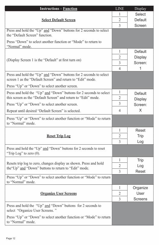
Instructions – Function LINE Display
Select Default Screen
1 SelectDefaultScreen
2
3Press and hold the “Up” and “Down” buttons for 2 seconds to select the “Default Screen” function.
Press “Down” to select another function or “Mode” to return to “Normal” mode.
(Display Screen 1 is the “Default” at first turn on)
1 DefaultDisplayScreen:
1
2
3
4
Press and hold the “Up” and “Down” buttons for 2 seconds to select screen 1 as the “Default Screen” and return to “Edit” mode.
Press “Up” or “Down” to select another screen.
Press and hold the “Up” and “Down” buttons for 2 seconds to select this screen as the “Default Screen” and return to “Edit” mode.
Press “Up” or “Down” to select another screen.
Repeat until desired “Default Screen” is selected.
1 DefaultDisplayScreen:
X
2
3
4
Press “Up” or “Down” to select another function or “Mode” to return to “Normal” mode.
Reset Trip Log
1 ResetTripLog
2
3
Press and hold the “Up” and “Down” buttons for 2 seconds to reset “Trip Log” to zero (0).
Resets trip log to zero, changes display as shown. Press and hold the“Up” and “Down” buttons to return to “Edit” mode.
1 TripLog
Reset
2
3Press “Up” or “Down” to select another function or “Mode” to return to “Normal” mode.
Organize User Screens
1 OrganizeUser
Screens
2
3
Press and hold the “Up” and “Down” buttons for 2 seconds to select “Organize User Screens. ”
Press “Up” or “Down” to select another function or “Mode” to return to “Normal” mode.
Page 13
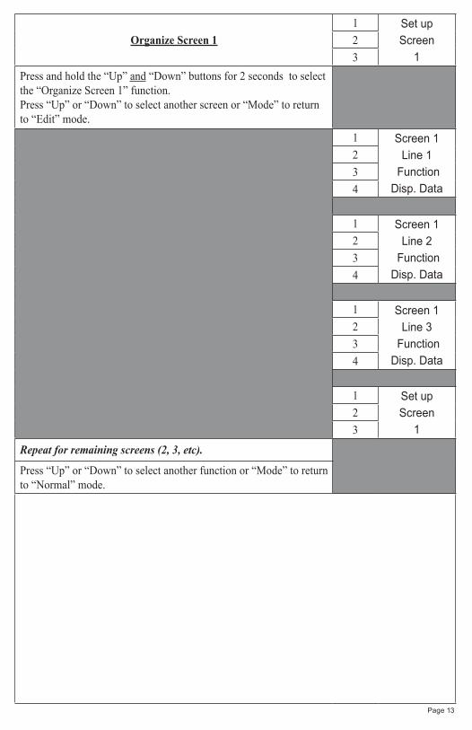
Organize Screen 1
1 Set upScreen
1
2
3
Press and hold the “Up” and “Down” buttons for 2 seconds to select the “Organize Screen 1” function.Press “Up” or “Down” to select another screen or “Mode” to return to “Edit” mode.
1 Screen 1Line 1
FunctionDisp. Data
2
3
4
1 Screen 1Line 2
FunctionDisp. Data
2
3
4
1 Screen 1Line 3
FunctionDisp. Data
2
3
4
1 Set upScreen
1
2
3
Repeat for remaining screens (2, 3, etc).
Press “Up” or “Down” to select another function or “Mode” to return to “Normal” mode.

Page 14
Select Adjust Clock Offset
1 AdjustClockOffset
2
3
Press and hold the “Up” and “Down” buttons for 2 seconds to select the “Adjust Clock Offset” function.Press “Up” or “Down” to select another function or “Mode” to return to “Normal” mode.
Press “Up” or “Down” to adjust the clock offset value.
Press and hold the “Up” and “Down” buttons for 2 seconds to save the clock offset and return to “Edit” mode.
Note: If the local time zone changes, this adjustment must be repeated.
1 AdjustClockOffsetHours
X
234
5
Press “Up” or “Down” to select another function or “Mode” to return to “Normal” mode.
Select Enable Display Screens
1 EnableDisplayScreens
2
3
Press and hold the “Up” and “Down” buttons for 2 seconds to select the “Enable Display Screens” function.Press “Up” or “Down” to select another function.
A box will appear around “On” if this display screen is “On.”
Press and Hold “Up” and “Down” to switch the box to the “Off” position. When the unit is returned to “Normal” mode, Display 1 will not be displayed.
Press “Up” to select the next display to be turned “On” or “Off.”
Refer to Figure 1 for display screen contents which will vary with engine type. Screen 1 shown is for reference purposes only.
When all display screens have been set “On” or “Off”, press “Down” to cycle back through the display screens if required.Press “Mode” to return to “Edit” mode.
1 Enable
Display 1
On Off
Clock
Fuel Level
Speed
2
3
4
5
6
Press “Up” or “Down” to select another function or “Mode” to return to “Normal” mode.
Select Set Clock Type
1 SetClockType
2
3
Press and Hold the “Up” and “Down” buttons for 2 seconds to select the “Set Clock Type” function.
Press “Up” or “Down” to select another function.

Page 15
Press “Up” or “Down” to scroll through the selections.
When the correct choice is next to the selection arrow.
Press and hold the “Up” and “Down” buttons for 2 seconds to save the selection and return to “Edit” mode.
1 SetClockType
24 Hour>12 Hour
2
3
4
5
Press “Up” or “Down” to select another function or “Mode” to return to “Normal” mode.
Select Set GPS COG Display
1 SetGPS COG
Display
2
3
Press and hold the “Up” and “Down” buttons for 2 seconds to select the “Set GPS COG Display” function.Press “Up” or “Down” to select another function.
Press “Up” or “Down” to scroll through the selections.When the correct choice is next to the selection arrow, Press and hold the “Up” and“Down” buttons for 2 seconds to save the selection and return to “Edit” mode.
1 SetGPS COG
DisplayTrue North>Magnetic
2
3
4
5
Press “Up” or “Down” to select another function or “Mode” to return to “Normal” mode.
Select Self Test
1 SelectSelfTest
2
3
Press and hold the “Up” and “Down” buttons for 2 seconds to select “Self Test”Press “Up” or “Down” to select another function.
This screen will display for 10 seconds,the backlights and warning lights will flash three times.
1 Self TestFaria
MG2000SW ID + Rev.PGFXXXXXX
Date
2
3
4
5
6
When the “Self Test” is complete the unit will return to the “Edit” mode.
Press “Up” or “Down” to select another function or “Mode” to return to “Normal” mode.

Select Software ID and Revision”
1 SW ID + Rev.Faria
MG2000SpeedometerPGFXXXXXX
Date
2
3
4
5
6
Press “Up” to select another function or “Mode” to return to “Normal” mode.
Page 16

Page 17
Alarm ModeThe “Alarm Screen” appears only if an alarm condition exists. The alarm condition may be a warning sent from the engine ECU or a “local” alarm such as “Low Fuel”. When an alarm condition occurs, the “Alarm Screen” will appear and the screens described below will be displayed.
The descriptions below also explain how to temporarily override the alarm screen and visual warnings and return to “Normal” mode. In all cases, the alarm will re-occur after a period of time to ensure that the user remembers the alarm condition. Once an alarm condition has been corrected, the alarm screen, and warning lights will no longer be displayed.
Alarm Mode Line Display
The “Alarm Screen” will appear if an alarm condition occurs.The alarms that appear in the Speedometer are “Low Fuel” and Low Oil Reserve.
Low Fuel – Low OILDisplays applicable warning (both if present)“Low Fuel” – Fuel level is critically low.“Low Oil” Level (Outboard 2 stroke only) – Oil level in the remote tank is low. Red Warning LED’s blinks.
1 LowFuel
!LowOil!
23456
Press “Mode” then push “Up” to turn off the Warning LED’s and return to “Run” mode. Alarm will reactivate in 10 to 15 minutes but can continue to be deactivated as required.
Alarm Screen (Showing both alarms)
Figure 4
MG2000 Tachometer
654321
789101112123
654
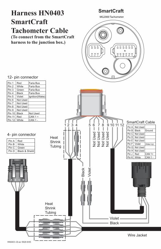
SmartCraftHarness HN0403SmartCraft Tachometer Cable(To connect from the SmartCraft harness to the junction box.)
4- pin connector
12- pin connector
Pin A RedPin B WhitePin C GreenPin D Black & Sheild
Pin 1 Red Faria BusPin 2 White Faria BusPin 3 Green Faria BusPin 4 Black Faria BusPin 5 Violet Ignition(Wake)Pin 6 Not UsedPin 7 Not UsedPin 8 Not UsedPin 9 Not UsedPin 10 Black Not UsedPin 11 Red CAN 1 +Pin 12 White CAN 1 -
SmartCraft CablePin A Not UsedPin B Black GroundPin C Not UsedPin D Not UsedPin E Not UsedPin F Violet (Wake Up)
Pin G Not UsedPin H Not UsedPin J Red CAN 1+Pin K White CAN 1 -
1 2 3 4 5 6 7 8 9 10 11 12
Wire Jacket
HeatShrinkTubing
HeatShrinkTubing
Vio
let
Violet
Bla
ck
Black
Not
Use
dN
ot U
sed
Not
Use
dN
ot U
sed
HN0403 r.B ecr 5629 8/05

Air Temp Sender
White (Sender Signal)
Black & Shield (Ground)
654321
789101112123
654
MG2000 Speedometer Harness HN0403Speedometer Cable
1 2 3 4 5 6 7 8 9 10 11 12
Wire Jacket
12- pin connectorPin 1 Red Faria Bus +8.4 VDCPin 2 White Faria Bus AYPin 3 Green Faria Bus BZ Pin 4 Black Faria Bus GroundPin 5 Not UsedPin 6 Not UsedPin 7 Tan Temp SignalPin 8 Not UsedPin 9 Not UsedPin 10 Not UsedPin 11 Not UsedPin 12 Not Used
Tan
Not
Use
dN
ot U
sed
Not
Use
dN
ot U
sed
Not
Use
dN
ot U
sed
Not
Use
d
GRN SIGNAL (SPEED)
BARE GROUND (SPEED)
RED + VOLTAGE (SPEED)
N/C WHT THERMISTER (TEMP)
N/C BRN THERMISTER (TEMP)
FARIA
Page 19

MG2000 Tachometer
654321
789101112123
654
SmartCraftHarness HN0407SmartCraft Tachometer Cable(To connect direct to the SmartCraft junction box.)
4- pin connector
12- pin connector
Pin A RedPin B WhitePin C GreenPin D Black & Sheild
Pin 1 Red Faria Bus +8.4 VDC Pin 2 White Faria Bus AYPin 3 Green Faria Bus BZPin 4 Black Faria Bus GroundPin 5 Violet Ignition(Wake)Pin 6 Not UsedPin 7 Not UsedPin 8 Not UsedPin 9 Not UsedPin 10 Black Not UsedPin 11 Red CAN 1 +Pin 12 White CAN 1 -
SmartCraft CablePin A Not UsedPin B Black GroundPin C Not UsedPin D Not UsedPin E Not UsedPin F Violet (Wake Up)
Pin G Not UsedPin H Not UsedPin J Red CAN 1+Pin K White CAN 1 -
1 2 3 4 5 6 7 8 9 10 11 12
Wire Jacket
HeatShrinkTubing
HeatShrinkTubing
Vio
let
Violet
Bla
ck
Black
Not
Use
dN
ot U
sed
Not
Use
dN
ot U
sed
HN0407 r.B ecr 5629 8/05

Air Temp Sender
White (Sender Signal)
Black & Shield (Ground)
654321
789101112123
654
MG2000 Speedometer Harness HN0407Speedometer Cable
1 2 3 4 5 6 7 8 9 10 11 12
Wire Jacket
12- pin connectorPin 1 Red Faria Bus +8.4 VDCPin 2 White Faria Bus AYPin 3 Green Faria Bus BZPin 4 Black Faria Bus GroundPin 5 Not UsedPin 6 Not UsedPin 7 Tan Temp SignalPin 8 Not UsedPin 9 Not UsedPin 10 Not UsedPin 11 Not UsedPin 12 Not Used
Tan
Not
Use
dN
ot U
sed
Not
Use
dN
ot U
sed
Not
Use
dN
ot U
sed
Not
Use
d
GRN SIGNAL (SPEED)
BARE GROUND (SPEED)
RED + VOLTAGE (SPEED)
N/C WHT THERMISTER (TEMP)
N/C BRN THERMISTER (TEMP)
FARIA
Page 21

Tachometer to 2” Gauge Connection
PJ0018
Note: To help reduce moisturein the gauges, be sure to install plug PJ0018 in all open connectors
2" Gauges
HN0503From Tachometer
4- pin connector
Pin A RedPin B WhitePin C GreenPin D Black & Sheild
Page 22


Copyright 2005 by the Thomas G. Faria Corporation, Uncasville CT No part of this publication may be reproduced in any form, in an electronic retrieval system or otherwise, withoutthe prior written permission of the company.Faria® is the trademark of the Thomas G. Faria Corporation