Is no-tension dam design always safe? -a numerical study · Fracture mechanics deals explicitly...
12
Is no-tension dam design always safe? -a numerical study Gustavo Gioia Graduate Research Assistant Northwestern University Evanston Illinois 60208 USA Zdenek P. Baiant Walter P. Murphy Professor of Civil Engineering Northwestern University Bert P. Pohl NSF Undergraduate Summer Research Trainee Northwestern University (on leave from University of Michigan, Ann Arbor) SUMMARY The paper examines the no-tension design of concrete gravity dams on the basis of finite element analysis. The no-tension assumption is implemented as a special case of plasticity in which the tensile yield limit tends to zero. This is compared with finite element analysis based on linear elastic fracture mechanics with either a realistic or a very small value offracture toughness. The crack pressure, which has a great influence on the results, is taken into account. Numerical counter-examples show that the widely held belief that no-tension design is safe is not always true. It follows that safety of dams should be evaluated on the basis of fracture mechanics. Introduction Concrete gravity dams are customarily designed using a simple stress-based failure criterion generally called "no-tension design". Although the basis for this method is always the assumption that concrete cannot resist tensile stresses, many different versions of no-tension design have beeT\ used. In its simplest form, suitable for hand calculations, no-tension design considers a linear compressive stress distribution throughout the uncracked portion of a given horizontal cross section, <Lnd equilibrium is then checked. Sophisticated versions of the method use full finite-element-based plastic analysis with a suitable yield surface. Fracture mechanics deals explicitly with crack propagation in the material by means of an energy balance, as proposed already in 1921 by Griffith. The brittleness of concrete and the conspicuous existence of cracks in gravity dams suggests that fracture mechanics could be a better approach to the problem of dam design than stress-based criteria. Nevertheless, no systematic study of the possible application of fracture mechanics as a basis for an alternative design method has so far been undertaken. This state of facts could be attributed to the great familiarity of civil engineers with stress-based methods of design-such as elasticity and plasticity-along wit.h the perception that fracture mechanics might prove too difficult to use. But the most important factor has been the claim that no-tension design lies always on the safe side. This claim has neller been justified theoretically. . Dam Engin •• ria, V.IIII I" •• 1 23
Transcript of Is no-tension dam design always safe? -a numerical study · Fracture mechanics deals explicitly...

Is no-tension dam design always safe? -a numerical study
Gustavo Gioia Graduate Research Assistant Northwestern University Evanston Illinois 60208 USA
Zdenek P. Baiant Walter P. Murphy Professor of Civil Engineering Northwestern University
Bert P. Pohl NSF Undergraduate Summer Research Trainee Northwestern University (on leave from University of Michigan, Ann Arbor)
SUMMARY
The paper examines the no-tension design of concrete gravity dams on the basis of finite element analysis. The no-tension assumption is implemented as a special case of plasticity in which the tensile yield limit tends to zero. This is compared with finite element analysis based on linear elastic fracture mechanics with either a realistic or a very small value offracture toughness. The crack pressure, which has a great influence on the results, is taken into account. Numerical counter-examples show that the widely held belief that no-tension design is safe is not always true. It follows that safety of dams should be evaluated on the basis of fracture mechanics.
Introduction
Concrete gravity dams are customarily designed using a simple stress- based failure criterion generally called "no-tension design". Although the basis for this method is always the assumption that concrete cannot resist tensile stresses, many different versions of no-tension design have beeT\ used. In its simplest form, suitable for hand calculations, no-tension design considers a linear compressive stress distribution throughout the uncracked portion of a given horizontal cross section, <Lnd equilibrium is then checked. Sophisticated versions of the method use full finite-element-based plastic analysis with a suitable yield surface.
Fracture mechanics deals explicitly with crack propagation in the material by means of an energy balance, as proposed already in 1921 by Griffith. The brittleness of concrete and the conspicuous existence of cracks in gravity dams suggests that fracture mechanics could be a better approach to the problem of dam design than stress-based criteria. Nevertheless, no systematic study of the possible application of fracture mechanics as a basis for an alternative design method has so far been undertaken. This state of facts could be attributed to the great familiarity of civil engineers with stress-based methods of design-such as elasticity and plasticity-along wit.h the perception that fracture mechanics might prove too difficult to use. But the most important factor has been the claim that no-tension design lies always on the safe side. This claim has neller been justified theoretically. .
Dam Engin •• ria, V.IIII I" •• 1 23
AddItional Pressurc Due to O\'crO,)w
Full Reservoir Pressure
14 m
~
( 12m )
Figure 1. Geometry and initial finite element mesh used in this study, applied loads, supports, and basic material properties.
At a recent international workshop (Dungar, et al., [1990]), the question arose whether fracture mechanics analysis could predict lower failure loads than no-tension design. With this motivation, a previous paper (Baiant [1991]) compared simplified versions of both approaches applied to dams with rectangular idealized geometry-=so as to make hand calculations possible. The conclusion was that no-tension design is not guaranteed to be on the safe side. In the present paper, we extend the comparison to rather sophisticated versions of no-tension- and fracture-mechanics- based analyses. Among other results, we present some counter-examples to the general claim that no-tension design lies always on the safe side. The importance of crack pressure-and the fact that no-tension plasticity is not appropriate for its consideration-is also discussed. 1t is demonstrated that the use of fracture mechanics is an imperative requirement for a realistic assessment of the failure modes and the safet: factors of concrete gravity dams.
1 Modeling
Figure 1 shows the model dam used in this study: the geometry, the initial finite element mesh, the applied loads and supports. The basic material properties, relevant to both no-tension plasticity and fracture mechanics, are: modulus of elasticity E = 25000 MPa, Poisson's ration II = 0.2,.mass density of concrete p = 2450 kg/m3. The dam shape and size correspond to the well-known Koyna. dam, which has been used extensively as a case study by numerous researchers. The finite elements are eight-node isoparametric, and the bottom of the dam is rigidly supported. Plane strain is assumed. Aside from the loads shown in Figure 1, internal crack pressure is assumed to be present in some of the numerical experiments.
24 » ... E.,. ••• ri., V.I III 1 .... 1

Figure 2. Ottosen's surface's trace onto four different r-planes.
1.1 No-tension plasticity
The no-tension approach to finite element analysis of concrete (or rock) was initiicilly introduced as a special case of the smeared cracking model with zero tensile stress (Zienkiewicz, [1977]). When a positive principal stress is detected at some integration point, the tensile stress its reduced to zero. The crack direction is set at that moment. If the subsequent )oadi~ causes again at that point a tensile principal stress in some other direction, a rigorous treatment requires thE! introduction of a new crack at the same point. This multidirectional cracking model presents serious problems (Rots, [1991)). An easy way to avoid them is to treat smeared tensile cra.c.killg by means of plasticity.
For this study, we adopt a perfectly plastic model with an associated flow rule :md a yield surface as proposed for plain concrete by Ottosen [1977]. Figure 2 shows the traces of this surface on the lI'-planes for the small values of hydrostatic pressure expected in a ~avity dam., corresponding to the first stress invariant values: II = -0.25, 0.25, 0.75 and 1.25 MPa. The cirdes are the loci of constant ..;J2 = 0.05, 0.10 and 0.15 MPa (h = second stress deviator invariant. The plot is for f; = 40 and f: =0.1 MPa. It is apparent that this is in essence a Rankine-Cou!lomb yield surface with smoothed-out corners-a very convenient feature from the computational stacndpoint.
Four parameters are needed to define Ottosen's surface. To determine them, w'e follow Torrent et al. [1987J in using the unjaxjal tensile and compressive strengths U: and /c), along with the failure stresses for certain biaxial and triaxjal compressive tests which can be expressed in terms of /c. The most relevant parameter in this model is /:, and we use several different values for it, as detailed later. On the other hand, all the results reported here correspond to a. unique vaJue of compressive strength /; = 40 MPa, although we also perform some numerical experiments using /; = 20 MPa. in order to verify tha.t the influence of f; is indeed negligible. A return-mapping algorithm as presented by Ortiz and Popov [1985J is used for the numerical integration of the model.
D.m E.,i ••• "., Vol 111 1" •• I 25

Figure 3 shows the plastic solutions for lhr('(' differ('nt valu('s of f:. reprl'sented as a plot of the overflow (height of overtopping) versus displacement at the top of tli!' dam. Thes·~ curves deserve some additional comments:
• The initial value of horizontal displacement ('" 0.Ql8 m) corr('sponds to the own weight (selfweight) plus the reservoir pressure (that is, the loads which were applied before any overflow). The control variable during the application of the overflow is the displacement at the top.
• Had the structural response been followed for even larger displacements-which was unnecessary here-the curves would have eventually reached a plateau, as expected from a perfectly plastic analysis.
• The value f: = 1.0 MPa is fairly typical for actual tensile tests on concretes customarily used in gravity dams.
• The no-tension design, strictly speaking, means zero tensile strength. To ensure uniqueness and stability, however, the theory of plasticity requires the origin of the stress space to lie within the yield surface. Thus, the tensile yield limit can be arbitrarily small, but not z'ero. Rigorously, the no-tension design ought to be considered as the limit of the plastic designs as the tensile yield limit tends to zero_
• There is a practical restriction on how close to zero the value of f; can be chosen. In fact, for small values of f: the elastic domain shrinks to a very narrow region around the hydrostatic axis (for the low values of pressure of interest). As a consequence, the algorithm fails to map the elastic predictor onto the elastic domain (note that the mapping is not radial). Although this could theoretically be solved by taking sufficiently small loading steps, for very low values of f:, the number of steps would then become unreasonably large. The results for f: = 0.1 MPa, however, can be considered for all practical purposes, the "no-tension" solution.
1.2 Fracture mechanics
The main problem when simulating propagation of a sharp crack is that it implies a continuously changing boundary-value problem. In the context of finite element analysis. following the propagation of a crack of an arbitrary path unknown in advance requires repeated re-meshing, a task that can only be performed efficiently by means of some sophisticated computational tool. For this study we adopt FRANC (FRacture ANalysis Code), a program developed at Cornell University (Wawrzynek, [1987]) as an extension of a previous work by A. R. Ingraffea. The program features automatic re-meshing and evaluation of the stress intensity factors, making fracture-mechanics analysis of arbitrarily curved cracks relatively straightforward.
Although FRANC can deal with nonlinearities-by means of cohesive stresses-woe. only use linear elastic fracture mechanics. This simplification is justified by our knowledge of the size effect in the fracture of quasi-brittle materials (Baiant and Kazemi, [1990]). In fact, the nonlinearity arises when the size of the fracture process zone is relatively significant compared with the size of the structure. Since the size of the fracture process zone is of the order of magnitude of the aggre~~ates (- O.2m), it is clear that for large structures such as concrete gravity dams the nonlinearity can be neglected.
Among the criteria for crack propagation available in FRANC we cho!e the so-called "U8 method", which not only predicts the h-I-K II pairs corresponding to the states of imminent cracck propagation, but also yields the ratio h- lIe/ h'le = j3f4 (Erdogan and Sih, [1963]) of the corresponding fracture toughness values for modes I and II. Thus, the only material parameter needed to define the fractur~ model is K/c. The issue of crack initiation is .not of our concern, and we assume that imperfections or initial cracks required for application of fracture mechanics to be valid already exist. We do not address the problem of several possible interacting cracks competing for propagation (Baiant and Tabbara, [1991]): all our examples fea.ture a single crack.
26 DAm £",i ••• ,;", Vol III 1, ... 1

Overflow (m)
20
15
10
5
0.01
Displacement at the Top (m)
Figure 3. Plastic solutions represented as a plot of the overflow versus the displacement at the top
of the dam.
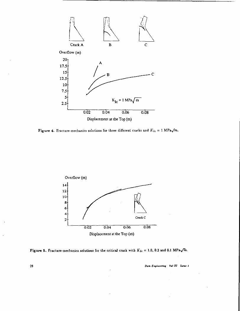
Figure 4 shows the fracture· mechanics solutions for cracks starting at three different points on the upstream face of the dam. All the curves correspond to K Ie = 1 MPa Jiii, a typical value. A series of comments on these curves is in order:
• All the curves are "hardening~, with a positive slope and no limit points. This contrasts with the characteristic failure mode usually associated with fracture mechanics, namely dynamic instability with swift crack propagation. This interesting behavior highlights the stabilizing effect of the own weight, which grows in importance as the crack propagates and succeeds in overcoming the destabilizing effect of the water loads .
• There exists a very short unstable branch for very small crack lengths. This is because the own weight requires a certain minimum crack length to become effective. As a consequence, any initial imperfection does not grow until the overflow reaches a certain critical value. Once this value is reached, the crack grows in an unstable fashion, until the own weight becomes effective
enough for the crack to grow stably.
The crack labelled "C" in Figure 4 (which originates in the upper portion of the dam) is the critical one. This conclusion SN'ms to be at odds with the notion, suggested by the beam-theory standpoint, that the critical cross-section should lie at the bottom of the dam. It is interesting to note that severe damage actually occurred at the location of crack "C" as a result of an earthquake striking Koyna dam in 1967 (Saouma et 01. [1990]). Therefore, all our further numerical .experimentation
with fracture mech;j.nics is based on crack ~C".
27
Crack A
Overflow (m)
20
17.5
15
12.5
10
7.5
5
2.5
B C
A
~B C
0.02 0.04 0.06 0.08
Displacement at the Top (m)
Figure 4. Fracture-mechanics solutions for three different cracks and [{Ie = 1 MPay""m.
Overflow (m)
14
12
10
8
6
4
2
0.02 0.04 0.06
Displacement at the Top (m)
Crack C
0.08
Figure 5. Fracture-mechanics solutions for the critical crack with [{Ie = 1.0,0.3 and 0.1 MPaym.
28 Dam E.,i ... ri., Vo/Ill I .... 1
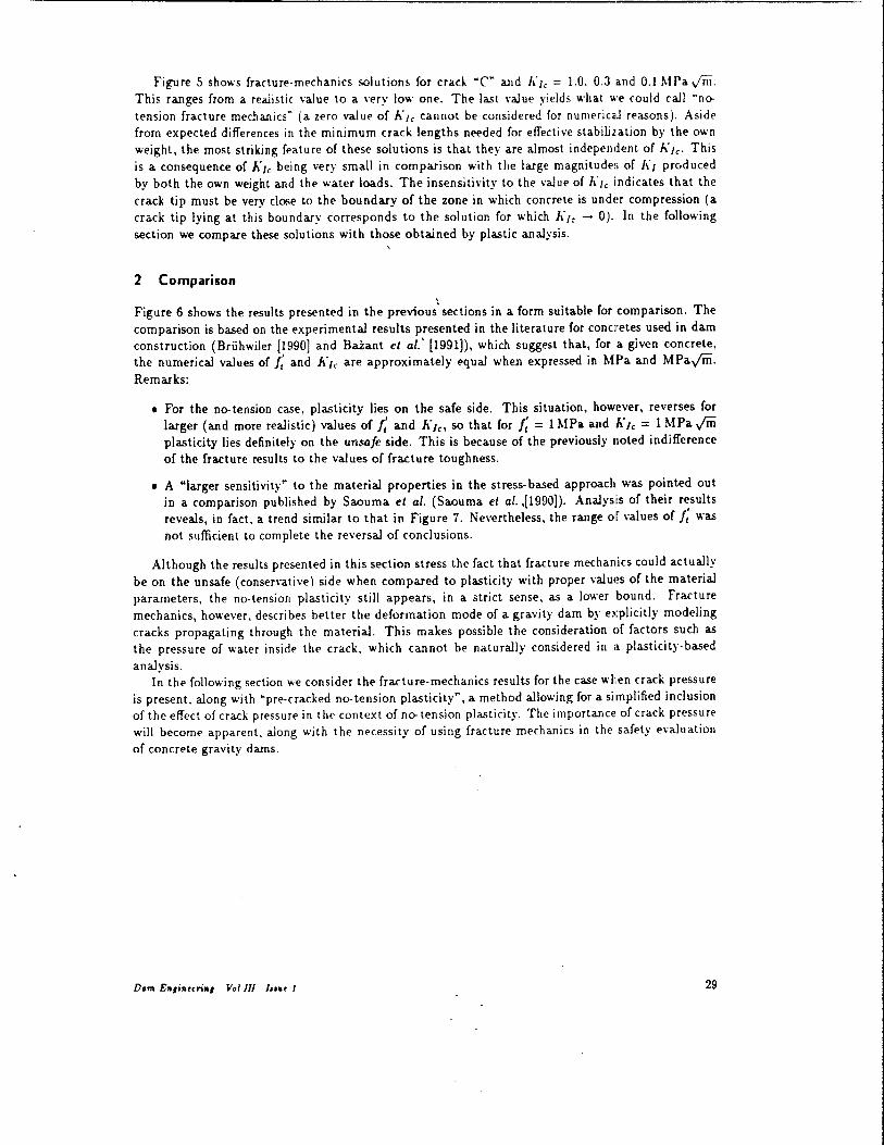
Figure 5 shows fracture·mechanics solutions for crack ~C~ and klc = 1.0. 0.3 and 0.1 MPa Jill. This ranges from a realistic value to a very low one. The last value yields what \\'1' could call Mno
tension fracture mechanicsM
(a zero val ue of J.: /e cannot be considered for numeric.J reasons). Aside from expected differences in the minimum crack lengths needed for effective stabilization by the own weight, the most striking feature of these solutions is that they are almost independent of h'/e. This is a consequence of h'/e being very small in comparison with the large magnitudes of 1\'/ produced by both the own weight and the water loads. The insensitivity to the value of A'/e indicates that the
crack tip must be very close to the boundary of the zone in which concrete is undE~r compression (a crack tip lying at this boundary corresponds to the solution for which A'/e - 0). In the following section we compare these solutions with those obtained by plastic analysis.
2 Comparison
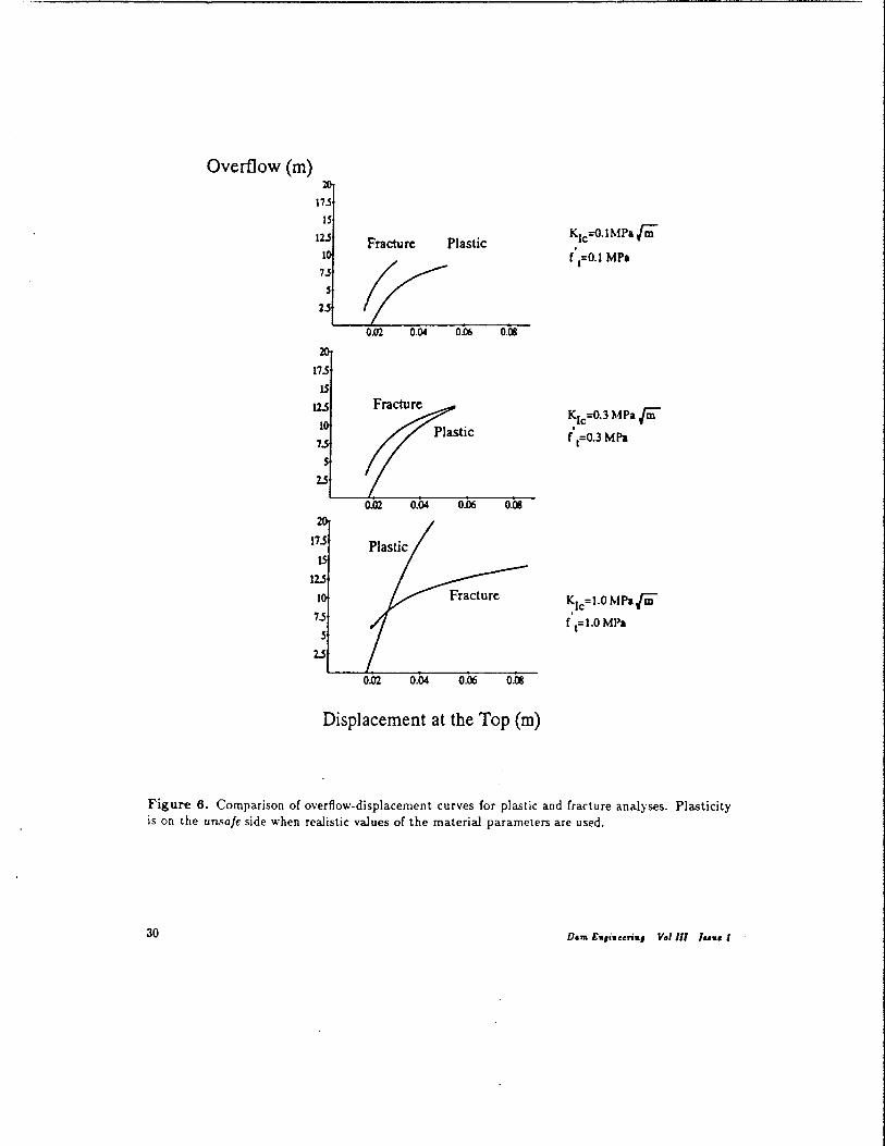
Figure 6 shows the results presented in the previous' sections in a form suitable for comparison, The comparison is based on the experimental results presented in the literature for conclretes used in dam construction (Briihwiler {l990) and Baiant et af.' (1991)), which suggest that, for a given concrete, the numerical values of J; and h'le are approximately equal when expressed in MPa and MPa.;m. Remarks:
• For the no-tension case, plasticity lies on the safe side. This situation, however, reverses for larger (and more realistic) values of J: and h'le, so that for ,: = 1 MPa and 1I"Ie = 1 MPa.;m plasticity lies definitely on the unsafe side. This is because of the previously noted indifference of the fracture results to the values of fracture toughness,
• A "larger sensitivity" to the material properties in the stress- based approach was pointed out in a comparison published by Saouma et al. (Saouma et al. ,[1990]). Analysis of their results reveals, in fact. a trend similar to that in Figure 7, Nevertheless, the range of values of ,: was not sufficient to complete the reversal of conclusions,
Although the results presented in this section stress the fact that fracture mechanics could actually be on the unsafe (conservative) side when compared to plasticity with proper values of the material parameters, the no-tension plasticity still appears, in a strict sense, as a lower bound. Fracture mechanics, however, describes better the deformation mode of a gravity dam by explicitly modeling cracks propagating through the material. This makes possible the consideration of factors such as the pressure of water inside the crack, which cannot be naturally considered in a plasticity-based analysis.
In the following section we consider the fracture-mechanics results for the case when crack pressure is present, along with "pre-cracked no· tension plasticity", a method allowing for a simplified inclusion of the effect of crack pressure in the context of no-tension plasticity. The importance of crack pressure will become apparent, along with the necessity of using fracture mechanics in the safety evaluation of concrete gravity dams.
Dom E",i" .. ri., Voflll Ian. 1 29
Overflow (m)
7.5
$
2.5
S
2.S
Fracture
t 0.Q2 0.04
Plastic
0.D6 0.08
0.06 0.08
Displacement at the Top (m)
KIc=O·lMParr;; . f ,=0.1 MPa
r ,=0.3 MPa
Figure 6. Comparison of overflow-displacement curves for plastic and fracture analyses. Plasticity is on the unsafe side when realistic values of the material parameters are used.
30 D.", E.,i ... ri., Vol 01 / ... , I

Overflow (m)
14
12
10
8
6
4
2
0.02
No-Tension. Plasticity f t=O.l MPa
Fracture KIc=1.0 MPa~ Triangular crack pressure
0.04 0.06
Displacement at the Top (m)
0.08
Figure 7. Effect on the fracture-mechanics results of water pressure (linearly distributed, with the full value at the mouth and zero at the tip).
3 Effect of crack pressure
Figure 7 shows the results obtained when crack pressure is added to the fracture analysis. In this case the pressure is linearly distributed along the crack length, with full pressure (full reservoir and overflow) at the crack mouth and zero pressure at the crack tip, implying water flow within the crack-a conservative assumption. Comments:
• The response includes the aforementioned characteristic unstable branch for small crack lengths. followed by a stable branch, stabilized by the own weight. Soon after, the influence of the crack pressure takes over, leading to a limit point and instability in the form of dynamic crack propagation .
• The failure value of overflow is much smaller than predicted by no-tension plasticity. Thus, this case is a clear counter·example to the general statement that no-tension design lies always on the safe side.
Figure 8 shows an additional counter-example obtained with a simplified fracture analysis consid· ering (i) the crack to propagate as a straight fracture, (ii) KI/ to be irrelevant, so that the propagation criterion can be written as h'l = Klc = 0, and (iii) the crack pressure to be uniform up to the tip (full pressure). The strong influence of the crack pressure is confirmed, but the assumption of straight crack propagation prevents the attaInment of a limit point.
The comparisons in Figures 7 and 8 could be considered improper because the plastic solution does not include crack pressure. The problem lies, however, in an intrinsic limitation of the plastic approach. In fact, no-tension plasticity deals with extensive regions of material incapable of bearing tensile stresses, where the concept of crack pressure does not make sense. In view of the importance of discrete cracks, plastic analysis is on occasions performed on a structure with a pre-existing crack OIl
Dam E.,i ... ri., V.I III I"., I 31

Overflow (m)
14
12
10
8
6
4
2
No-Tension, Plasticity f t=0.1 MPa
Fracture KLc=O Full craCK pressure
0.02 0.04 0.06 0.08
Displacement at the Top (m)
Figure 8. Example obtained with a simplified fracture analysis and full (uniformly distributed) crack pressure.
which the crack pressure can be taken into account, a procedure which could be called "pre-cracked no-tension plasticity".
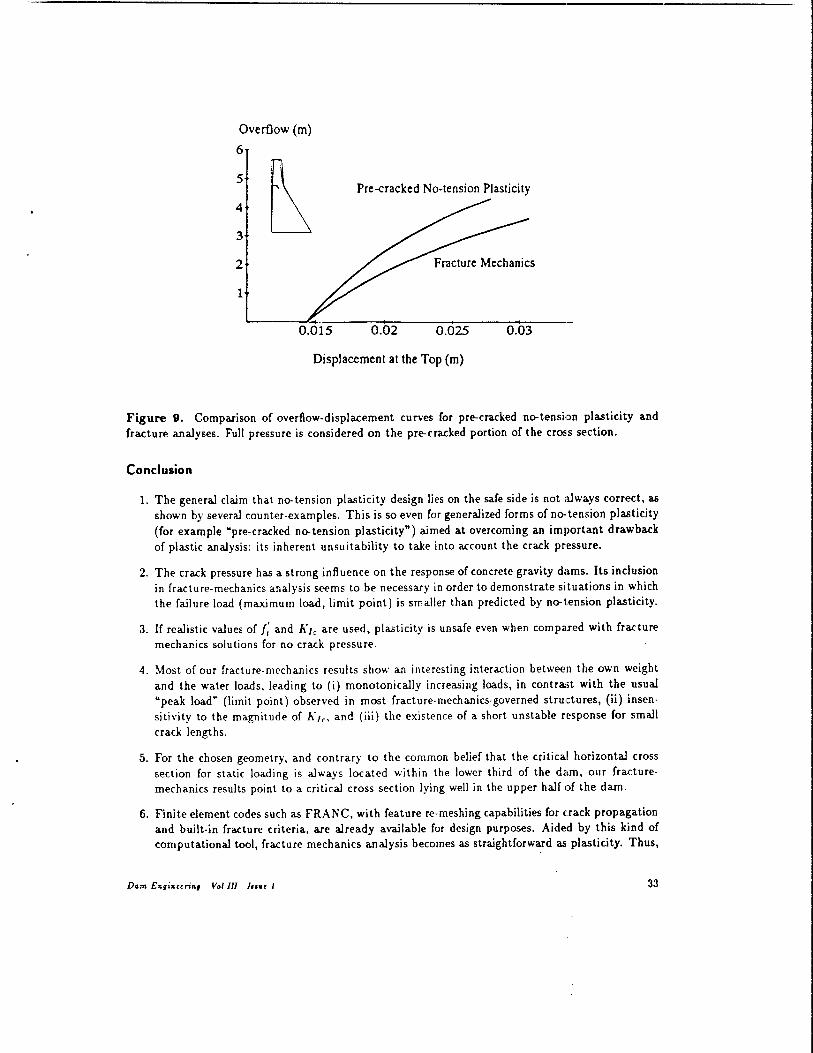
Figure 9 compares fracture mechanics with pre-cracked no-tension plasticity for a dam with an initial horizontal crack spanning 40% of the cross-section. This could be a preexisting crack caused, for example, by temperature and shrinkage differences across the construction joint between concrete layers. Full crack pressure is considered on the pre-cracked portion only (it would not be possible to do otherwise in the plastic case). Figure 9 is an additional counter-example for the assumption of safety of no-tension design.
32
Overflow (m)
6
5
~ 4
3
Pre-cracked No-tension Plasticity
2
1
0.015 0.02 I
0.025 0.03
Displacement at the Top (m)
Figure 9. Comparison of overflow-displacement curves for pre-cracked no-tension plasticity and fracture analyses. Full pressure is considered on the pre-cracked portion of the cross section.
Conclusion
1. The general claim that no-tension plasticity design lies on the safe side is not a.lways correct, as shown by several counter-examples. This is so even for generalized forms of no-tension plasticity (for example "pre-cracked no-tension plasticity") aimed at overcoming an important drawback of plastic analysis: its inherent unsuitability to take into account the crack pressure.
2. The crack pressure has a strong influence on the response of concrete gravity dams. Its inclusion in fracture-mechanics analysis seems to be necessary in order to demonstrate situations in which the failure load (maximum load, limit point) is smaller than predicted by no-t.ension plasticity.
3. If realistic values of f: and h'le are used, plasticity is unsafe e.·en when compa.red with fracture mechanics solutions for no crack pressure.
4. Most of our fracture-mechanics results show an interesting interaction between the own weight and the water loads, leading to (i) monotonically increasing loads, in contrast with the usual "peak load" (limit point) observed in most fracture·mechanics-governed structures, (ii) insensitivity to the magnitude of h'le, and (iii) the existence of a short unstable response for small crack lengths.
5. For the chosen geometry, and contrary to the common belief that the critical horizontal cross section for static loading is always located within the lower third of the dam, our fracturemechanics results point to a critical cross section lying well in the upper half of the dam.
6. Finite element codes such as FRANC, with feature re-meshing capabilities for c:rack propagation and built-in fracture criteria, are already available for design purposes. Aided by this kind of computational tool, fracture mechanics analysis becomes as straightforward as plasticity. Thus,
D.m E",i"«",,, Vol III I" .. I 33
putativl' difflcuiti(,5 "'Ith practICal fra<tur(' n1('chanics analY~ls arl' in fact nonl'xistent, and should not pr(,I'('nt thl' us!' of fracturf' m£'chanics in th(' J£'sign and safpty I'valuation of larg(' concrete gravity dams,
Bibliography
z. p, BAZA NT, ~ A Critical Appraisal of 'No- Tension' Dam Design: a Fracture ~1echanics Viewpoint", Dam Engineo·l7lg. 1(4): 1991; with errata to Table 2 and Figure 2 in 2(4); 1992. Z. P. BAZANT AND M. T. KAZEMI, ~Size Effect in the Fracture of Ceramics and Its Use to Determine Fracture Energy and Effective Process Zone Length", J. of the American Ceramic Society, 73(7); 1990. Z. P. BAZANT, S. HE, M. E. PLESHA. R. GETTU AND R. E. ROWLANDS, ~Rate and Size Effects in
Concrete Fracture: Implications for Dams", Proceedings, International Conference on Dam Fracture, University of Colorado, Boulder, Edited by V. Saouma, R. Dungar and D. Morris, pp 413 - 425; September 1991. Z. P. BAiANT AND M. R. TABBARA, ~Bifurcation and Stability of Structures with Interacting Propagating Cracks", lnt. J. of Fracture, accepted for pu bllication; 1991. E. BRUHWILER, "Fracture of Mass Concrete under Simulated Seismic Action", Dam Engineering, 1(3); 1991. R. DUNGAR, V. E. SAOUMA AND F. H. WITTMAN (EDITORS), "Workshop Notes, Research Workshop on Application of Fracture Mechanics to Dam Engineering", Proceedings, published by ETH (Swiss Federal Institute of Technology), Zurich; 1990. F. ERDOGAN AND G. C. SIH, "On the Crack Extension in Plates under Plane Loading and Transverse Shear", J. of Basic Engineering, 85; 1963. M. ORTIZ AND E. P. POPOV, "Accuracy and Stability of Integration Algorithms f,or Elastoplastic Constitutive Relations", Int. J. Numerirol Methods in Engineering, 21; 1985. N. S. OTTOSEN, "A Failure Criterion for Concrete", J. of Engineering Mech. Div., li03(EM4); 1977. J. G. ROTS, "Smeared and Discrete Representations of Localized Fracture". lnt. J. of Fracture, 51; 1991. V. E. SAOUMA, E. BRUHWILER AND H. L. BOGGS, "A Review of Fracture Mechanics Applied to Concrete Dams", Dam Engineering, 1(1); 1990. R. J. TORRENT, E. N. DVORKIN AND A. M. ALVAREDO, ~A Model for Work-Hard,ening Plasticity and Failure of Concrete under Multi-axial Stresses", Cement and Concrete Research" 17; 1987. P. A. WAWRZYNEK, "Interactive Finite Element Analysis of Fracture Processes: An Integrated Ap
proach", Engineering Report, Cornell University; 1987. O. C. ZIENKIEWICZ, "The Finite Element Method in Engineering Science", Book, McGraw-Hill,
London, Chapter 18; 1971.
34 Dam En,;" .. "", Vol 111 I" •• 1