IS 9178-3 (1980): Criteria for Design of Steel Bins for...
75
Disclosure to Promote the Right To Information Whereas the Parliament of India has set out to provide a practical regime of right to information for citizens to secure access to information under the control of public authorities, in order to promote transparency and accountability in the working of every public authority, and whereas the attached publication of the Bureau of Indian Standards is of particular interest to the public, particularly disadvantaged communities and those engaged in the pursuit of education and knowledge, the attached public safety standard is made available to promote the timely dissemination of this information in an accurate manner to the public. इंटरनेट मानक “!ान $ एक न’ भारत का +नम-ण” Satyanarayan Gangaram Pitroda “Invent a New India Using Knowledge” “प0रा1 को छोड न’ 5 तरफ” Jawaharlal Nehru “Step Out From the Old to the New” “जान1 का अ+धकार, जी1 का अ+धकार” Mazdoor Kisan Shakti Sangathan “The Right to Information, The Right to Live” “!ान एक ऐसा खजाना > जो कभी च0राया नहB जा सकता ह ै” Bhartṛhari—Nītiśatakam “Knowledge is such a treasure which cannot be stolen” IS 9178-3 (1980): Criteria for Design of Steel Bins for Storage of Bulk Materials, Part 3: Bins Designed for Mass Flow and Funnel Flow [CED 7: Structural Engineering and structural sections]
Transcript of IS 9178-3 (1980): Criteria for Design of Steel Bins for...

Disclosure to Promote the Right To Information
Whereas the Parliament of India has set out to provide a practical regime of right to information for citizens to secure access to information under the control of public authorities, in order to promote transparency and accountability in the working of every public authority, and whereas the attached publication of the Bureau of Indian Standards is of particular interest to the public, particularly disadvantaged communities and those engaged in the pursuit of education and knowledge, the attached public safety standard is made available to promote the timely dissemination of this information in an accurate manner to the public.
इंटरनेट मानक
“!ान $ एक न' भारत का +नम-ण”Satyanarayan Gangaram Pitroda
“Invent a New India Using Knowledge”
“प0रा1 को छोड न' 5 तरफ”Jawaharlal Nehru
“Step Out From the Old to the New”
“जान1 का अ+धकार, जी1 का अ+धकार”Mazdoor Kisan Shakti Sangathan
“The Right to Information, The Right to Live”
“!ान एक ऐसा खजाना > जो कभी च0राया नहB जा सकता है”Bhartṛhari—Nītiśatakam
“Knowledge is such a treasure which cannot be stolen”
“Invent a New India Using Knowledge”
है”ह”ह
IS 9178-3 (1980): Criteria for Design of Steel Bins forStorage of Bulk Materials, Part 3: Bins Designed for MassFlow and Funnel Flow [CED 7: Structural Engineering andstructural sections]


IS : 9178 (Part III ) - 1980
Indian Standard
Reaffirmed 2010
CRITERIA FOR DESIGN OF STEEL BINS FORSTORAGE OF BULK MATERIALS
PART 111 BINS DESIGNED FOR MASS FLOW AND FUNNEL FLOW
I N D I AN S T A N D A R D S I N S T I T U T I O NBHAVAN, 9 BAHADUR SHAH ZAFAR MARG
N E W DELHI 110002 January 1982
© Copyright 1982
MANAK

Is : 9178 ( Part III ) • 1980
Indian Standard
CRITERIA FOR DESIGN OF STEEL BINS FORSTORAGE OF BULK MATERIALS
PART III BINS DESIGNED FOR MASS FLOWAND FUNNEL FLOW
Structural Engineermg Sectional Committee, SMllDC 7
Chairman
DIRECTOI: Sl'ANIJARDS ( CIVIT, )
A[""bers
SnRI R. i\f AGAR'VAL
DIt Puuv KurSUN ~ ( Alternal. )SUIH A K IlAXLltJEI'.
Repr;se"llng
Mimstry of Railways
Insriturion of Engineer' ( Inrha }, Calcutta
Metallurgic d and Engrncerrng Consultantsl India) Ltel, Ranchi
Sum S. SA"KARAN (Allerrral' )Slim P. G. ihnDIIAN Brauhw.ntc & Co Lt,l, Ca lcutra
:::. HI":::' K t; ,,,COPAllIlY, Y (Altemale )SlIIlI S, N BASU Inspccuon Wing, Drrecrorate General of Supplies
ami D.'pm"h, New DellnSII'" D Il I ~1'1 (AIJ,mal' )
Sru.t P. C JIll 1"'1 Mrmsrrv ofS!Jippilll'; -md Transport (Departmentut I'rnnvpor-t ) ( Road, WIIII'; )
DIt 1'. N CIH'." L" TEl" Government 01 W"'tBengalDR P D,YA"A I '1A" Indr.m Institute of Technology, Kanpuri:>lilti D S J)"" 1\1. N. Dastur & Co PH Ltd, Calcutta
:::'1I1<lS R. KIILhA,,,t (.Ilfemate)Dnu i rou l l",A ~~~l«"liN) Ccntr.rl Elccn rcitj Authority, New Deihl
D,.'un ])JLtI' 1"" l11"'5-l\l1~~IO"'f ) \ Allemllte)
Sunr Z II" 'N Cenn al Water Comrmss ion, New DdlnSuut V. NAr:AL'" '" (.W,mal')
JOI:>l1' DIRJ.~j'O" S T \" "A u JI 8 Muustry of Railways(B & S)
1\88'81'\'1" Dllnl run ( B & S)sn ( Alternate )
jvr" r DIHLLrllI' (D.,,,,",,") Natronal Burldrngs Orgaruzution, New DelhiSum K S S1U"I\AS,':>I ( .Jllernal.)
SIIHI KAH.'llK PR~S \U Indian Roads Congress, New DelhiSHIU:::' C, CIHK"'llAllTI (.lllernal' )
{ Cnnllnwd on page :2 }
@ COPYrlghl 198t
INDIAN STANDARDS INSTITUTION
Thu publicanon II protected u.ider the Indian Copy"ghi Acl ( XIV of 1957) andreproducllon 10 whole or ID part by any means except with written permission of thepUblisher shall be deemed to be an inCflngement oC copyright under the ,aId Act.

IS z 9118 ( Part DI) • 1980
Ind ia,
Representlll,
Jessop & Co Ltd, Calcutta
( COflhlllUd ftl1/1l "",e I )
Members
SHIU P. K. MALLICK8Hm T S. BAGCHI ( AlttTMte )
SHIU S. K. MUKHEIlJEE Bridge & Roof Co ( India) Ltd, HowrahSHIll n. K CHATTERJEll ( Alternate)
Salll P V. NAIK RIchardson & Cruddas Ltd, BombaySnRI V. G. MANORULKAR (Allernate )
SHill DILIF PAUL Industrial Fasteners Association ofCalcutta
Bmny Ltd, MadrasSHin N RADHAKRISHNANSHIn P. ApPA RAO ( Alternate)
SIun N. V. R....tAN Structural Engineermg Research Centre, MadrasDn T. V. S. R. ApPA RAO ( Alternate)
SHIll C. S, s RAO Engmeer-in-Ohrefs Branch, Ministry ~r DeCellceREPIlESENTATlVE Tata Consultrng Engmeers, New DeihlREPRESENTATIVE Hindustan Steel Works Construction Ltd,
CalcuttaRail Indian Technical and Economics Services,
New DeihlSlun A B. RIBEIRO
SHIll S K BUANDT ( AlltTnate)SHill P SENGUP1'A Stewarts & Lloyds of India Ltd, Calcutta
SHIll M. M. GnOSH (A.lternate)SH1U M. M. SUENOY JOInt Plant Committee, Calcutta
SHRl D. SRINIVASAN (Allt:rnale)Snm C. N. SRINIVASAN CR. Narayana Rao, Karpagambal Nagar, Martras
SIIIlI C N RAG1IAVENDIIAN (AlltrMle)SHIll G SIlmp'A"AN llharat Heavy Electrrcals Ltd, "I'iruchirapalh~HJlJ H. K. TANJ!JA Indran Register of Shipping, Bombay
SHEI D SAIlANGDIlAR (Alternale)SHIll M. D. [HAMDEKAR Bombay Port Trust, BombayOil D. N TI<lKIIA UllIverSity uf Roorkee, RoorkeeSHIll L. D W"IlHWA Engineers India Ltd, New Delhi
S" III 1l fl. NAG ( Altemate )SlIIlI C R. RAMA R w Director General, lSI ( &-offim Membn)
Director ( Struc & Met)
Secrefarres
S1InI S. S SETHIDeputy Director ( Struc & Met l, lSI
SnRI V G HIREMATHASSIStant Drr ecror ( Struc & Met ), lSI
Subcommittee for Use of Steel in Bulk StorageStructures, 5MBDC 7 : 4
COfll.Jener
SURI N K. Roy
!>l,mN'sSHRI S. K. CHATTERJEESHI<I S. GOJ'ALAE:RISHNAN
SHRI S. SELVARAJ (Alter,..le lSHill GUI'CHAIUN SINGHSunr K VEEIlARAOIlA \'Al'UARY
The Fertilizer (Planning and Development}India Ltd, Smdn
Cement Corporation of India Ltd, New DelhiStructural Engmeerrng Research Centre, Madtas
Food Corporation of India, New DelhiBharat Heavy Electrrcals Ltd, Tiruchlrapalli
2

MARCH 1984AMENDMENt NO. 1
'to
IS: 9178 ( Part III )-1980 CRITEIUA FORDESIGN OF STEEL BINS FOR STORAGE OF
BULK MATERIALS
PART'" SINS DESIGNED FOR MASS FLOW ANDFUNNEL FLOW
Col'rilead1lm<
( PQge 31, claus« ]2.2.~.2, lfUQIWII 10 ) - Substitute the following f,the existing equation:
H [ ~- (-~ r. P, . ~.d ]
( 2 - O"hin 8)lD X {sin 6 + cos I} • tan ah ). ... (ll
(SMBDC 7:
IS: 9178 (Part JIJ ) .1980
Indian StandardCRITERIA FOR DESIGN OF STEEL BINS FOR
STORAGE OF BULK MATERIALS
PART III BINS DESIGNED FOR MASS FLOWAND FUNNEL FLOW
e, FOREWORD
0.1 This Indian Standard (Part III) was adopted by the IndianStandards Institution on 7 July 1980, after the draft finalized by theStructural Engineering Sectional Cornrmttee had been approved bythe Structural and Metals Division Council and the CIVIl EngineeringDivision Council,
0.2 Bins are known as silos if they have circular or polygonal shape inplan. When square or rectangular in plan they are known as bunkers. Inthis standard. bin shall mean both silos and bunkers unless otherwisestated.
0.3 The functions of bins as storage structures are very important in powerstations, fertilizer complexes, steel plants, cement plants and other similarindustries for efficient storage and use of bulk material in both granularand powdery form. On the agriCultural front bins are used to store food.grains for ensuring their supply throughout the year. Bulk storage ofmaterials in bins has certain advantages over other forms of storage. AnIndian Standard on this subject has, therefore, been a long fclt need andthis standard is armed at givmg the necessary guidance III the analysis anddesign ofsteel bins for storing various materrals of different characteristicsand flow properties.
0.4 Bins have been designed on the basis of Janssen's Theory (withmodifications to the original). From experimental investigations and astudy of the performance of the existing bins, it has been noticed that thepressure distribution is influenced by the size and shape of the material tobe stored ( that is granular or powdery), moisture and temperature, bulkdensity, which, in turn, are affected by storage and flow characteristics.Besides, there is increase in the imposed loads during filling and emptying,the latter being more predominant.
0.5 For reasons mentioned above, in the bins designed by conventionalmethods, materials do not easily flow due to arching and piping. This
3

IS I 9178 (Part III) • 1980
requires frequent poking - manually, pneumaticallv, with steam or byother mechanical means. With rr-sr-arch data available, this problem hasbeen successfully solvcd by adnpting mass Iluw or funnel flow bins wherethe shape of the bin hopper and the size of the openmg, are based on theflow properties of the stored material.
0.6 In this part of the code the present thmking on the design of massflow and funnel flow bunkers based on jernke's work is explamed. Furtherresearch in this field is cnntinuJO'; and it will not be possible to give aumvcrsal approach for all rnaterrals under varymg scrvrce conditions.This standard has lunitauons winch are explained in Appendix Awith proper reference. It i" therefore, suggested that designers shouldconsider all these aspects while adopting the recommendations given inthis code.
0.7 In order to deal with the subject 10 an effective manner this standardhas been prepared in three parts, namely,
Part I General requirements and assessment of loads.
Part rr Design crrreria,
Part III Bins designed for mass flow and funnel flow.
0.8 This standard keeps in view the practices being followed in Indiaand elsewhere in the field. Assistance has also been derived from thefollowing publications:
I. DIN 1055 (Sheet 6) Design loads for building bins, issued byDeutsche Norrnenausschluss.
2. Pressure distribution in bins (in German) Pioper K., andWenzel, F. Verlag Vom Wilhelm Erust & Sohn, Berlin,Munchen, 1964.
3. Bins and bunker for handling bulk material" Reisner, \V" andRothe, M E. Trane-Tech. Publication, Ohio, USA
4. Jenike, A. W.; Storage and flow of solids, Bull 123 (UtahEngmeering Experiment Station, Unice. of Utah, U.S A. ),1964.
5. Jenike, A. W.;Johanson, JR.; Carson,J. W.; Bin loads - Part 2~
Concepts, bin loads - Part 3: Mass flow bins, bin loads - Part 4:Funnel flow bins, Published in the' Journal of Engineering fonIndustry' Feb 1973 by American Society of MechanicalEngineers.
0.9 Recommended literature for reference is given in Appendix B.
0.10 For the purpose of deciding whether a particular requirement of thisstandard is complied with, the final value, observed or calculated, express,ing the result of a test or analySIS, shall be rounded off in accordance with
4

IS: 9178 (Part III) • 1980
IS : 2-1960"'. The number of significant places retained in the rounded offvalue should be the same as that of the specified value in this standard.
SECTION I GENERAL
I. SCOPE
1.1 This standard (Part I II) dl'.lls with the design of steel brns forstorage of bulk materials ensuring satisfactory mass How and funnel How( plug flow) under gravity flow In the case of powdery and granularmaterials.
2. TERMINOLOGY
2.1 For the purpose of this standard, the definitions given in Parts I andII in addition to the following definitions shall apply.
2.1.1 Active Pressure Field- The field in which the major pressure isvertical or near vertical.
2.1.2 Arched Pressure Fields - In arched pressure fields major pressurelines arch across flow channels, synonymous with "passive pressure" insoil mechanics.
2.1.3 Charger - Deposition of bulk solid into a bin, usually hy droppingin or blowing III from above.
2.1.4 Cylinder - Vertical part of a bin.
2.1.5 Draw - Withdrawal or feeding of bulk solids from a bin.
2.1.6 Flow Channel - Space through which a bulk solid is actuallyflowing during draw.
2.1.7 Flow Pressure - Pressure which the material exerts on the wallsof a bin during flow
2.1.8 Funnel or Plug Flow - The flow pattern in which the materialflows primarily in the central region of the bin or hopper.
2.1.9 Initial Pressure - Pressure exerted by bulk solids on the walls ofthe bin during and after charging, but before any withdrawal of thematerial.
2.1.10 Mass Flow - Flow in which the entire mass of material flowswithout stagnation.
2.1.11 Passive PrUSUTt Field - Field in which the major pressure ishorizon tal or near horizonta I.
·Rules for rounding off numerical value. (w.ued).
5

IS I 9178 (Part III) .1980
2.1.12 Peaked Pressure Fields - In peaked pressure fields major pressurelines from peaks at the centre of the bin, synonymous wrth "activepressure" in soil mechanics.
2.1.13 Radial Pressure Field - Field which occurs in the lower part ofa hopper and in which pressures are proportional to the distance fromthe vertex of the hopper.
2.1.14 Strain Energy - The energy of a flowing mass of solid whichcould be recovered by a relaxation of boundary forces and displacements.
2.1.15 Switch - Region of change of an active pressure field towardsa passive pressure field.
2.1.16 Transition -Joint between the cylinder wall and the conicalflow channel in a funnel flow bin, In mass flow it is the joint betweencylinder and hopper.
standard the notations as given below shall
= Mmor dimension of the outlet, m= Major dimension of the outlet or length of the opening
( slot length ), m
= Diameter of the opening of hopper, m
= Diameter of a circular cylinder, that is. dia of vertical,portron of storage system, width of rectangular Orsquare cylinder, m
- Height of the cylinder, m
= Coefficient, m = 0 for wedge hopperm = I for conical hopper
= Distance from the axis of symmetry. ill
= Bulk density of the solid, kg/m3
= Area of horizontal section of a cylinder, mS
= Diameter of hopper, width of a hopper, m
= Unconfined yield force of bulk solid, kgf
= Hydraulic radius = A/V
= Perimeter of the cross-section of the stored material, m= Shearing force, kgf= Janssen's pressure line= Depth of the fill in the cyhnder, m
= Fnctional stress on the bin wall, kgf/m l
= Frictional stress on the hopper wall, kgf/m l
wAB
FRVS]
r
mh
3. NOTATIONS3.1 For the purpose of thisapply:
bo
10
6
As
Rj
if, ill
vr
Enwn
H (O)
IS I 9178 (Part 111 ) • 1980
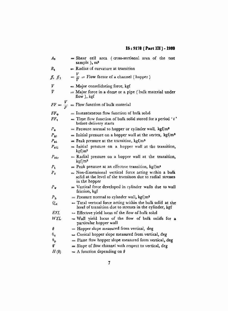
= Shear cell area (cross-sectional area of the testsample), m2
= Radius of curvature at transitionV
= r = Flow factor of a channel (hopper)
= Major consolidating force, kgf
= Major force in a dome or a pipe ( bulk material underflow), kgf
= Flow function of bulk material
= Instantaneous flow function of bulk solid
= Time flow function of bulk solid stored for a period' I 'before delivery starts
= Pressure normal to hopper or cylinder wall, kgf/m2
= Initial pressure on a hopper wall at the vertex, kgfjm l
= Peak pressure at the transition, kgf/m l
= Initial pressure on a hopper wall at the transition,kgf/m2
= Radial pressure on a hopper wall at the transition,kgf/m2
= Peak pressure at an effective transition, kgf(m2
= Non-dimensional vertical force acting within a bulksolid at the level of the transition due to radial stressesin the hopper
= Vertical force developed in cylinder walls due to wallfriction, kgf
= Pressure normal to cylinder wall. kgfjm2
= Total vertical force acting within the bulk solid at thelevel of transition due to stresses in the cylinder, kgf
= Effective yield locus of the How of bulk solid= Wall yield locus of the flow of bulk solids for a
particular hopper wall= Hopper slope measured from vertical, deg
= Conical hopper slope measured from vertical, deg
= Plane flow hopper slope measured from vertical. deg= Slope of flow channel with respect to vertical, deg
= A function depending on ()
7

IS I 9178 (Part 111) - 1980
rPG (1))
ii
ii'
a
= Kinematic angle of internal Irrction of bulk solid, deg
= A function depending upon r/l- Effective angle of wall friction of bulk solid on the
walls of the bin, deg= Kinematic angle of wall friction between bulk solid
and wall of bin, deg
I::: Angle of friction between bulk solid and hopper wall,deg
= A function depending on ii'= Coefficient of friction between the bulk solid and the
cyLinder wall
= Pressure ratio, that is, horizontal to vertical pressure
= Pressure, kgfJm 2•
4. DESIGN CONSIDERATIONS
4.1 In the design of bins for bulk storage, the two important considerations involved are:
a) flow characteristics, and
b) load distrrbution characteristics of the stored material.
".1.1 The now characteristics determine the slope of the hopper portionof the bill and the outlet dimeusions wlnch indrrecrlv lead to the selecnonof shape and Sl ze of the bID. These are dealt wlth'in detail In Section 2and Section 3 of the code for mass flow and funneL /low respectively.
4.1.'2 Load distrrbution characteristics give the actual loading conduionon the walls of the bm and at the ouuct, The-se govern the structuraldesign of the bin as well as the selection of the feeder system to be incorporated at the outlet. This has been dealt with In detail in Section 4 ofthe code.
SECTION 2 DESIGN FOR MASS FLOW
5. GENERAL
5.1 In mass flow, the contents of the hopper move at all points and slidingtakes place at the walls whenever any solid is drawn through the outlet ofthe bin, Inactive or dead regIOns are absent III the stored mass. Massflow IS a gravlt)' flow without any flow promoting device.

Is t 9178 (I'art tit) • 1910
5.2 Mass flow has the fallowing characteristics which guide the selectionof the design parameters:
a) Channelling, hang-ups, surging and flooding are absent,b) Flow is uniform, and steady state flow can be achieved closely,c) Pressure throughout the mass and at the walls is relatively low,
which results in low consolidation or packing,
d) There are no dead regions within the bin; hence there isminimum of consolidanon at rest.
e) A first-in-first-out How pattern may be obtained, if desired ThisIS useful in the storage of solids which either deteriorate With timeor segregate during charging
f) By circulating a mixture around a suitable bin, blending may beattained.
5.3 Mass flow storage bins may be designed with a variety of hoppershapes listed below ( see Fig. I ):
a) Conical or pyramidal hoppers with circular or square outlet,b) Chisel hoppers with rectangular outlet or slot,c) Transition hopper with rectangular outlet,d) Wedge hopper with full slot or rectangular outlet.
5.4 This standard covers the various hopper shapes given in 5.3 under thefollowing two distinct grou ps:
a) Conical channel with square or circular outlet,b) Plane flow channel with rectangular or full slot outlet.
6. FACTORS INFLUENCING THE DESIGN
6.1 Flow Properties of Stored Bulk Solids - The flow properties ofbulk solid stored in the bin is the principal factor affecting the design.These properties shall be determined under similar conditions of the bulkmass as It is stored in and delivered by the bin being designed. Factorsaffecting the flow properties are as follows:
a) Particle size and shape,b) Bulk density and consolidation,
c) Moisture content,
d) Temperature,e) Surface finish of bin walls, andf) Period of storage.
The flow properties shall be determined after considering thesefactors in the actual storage conditions. The flow properties thus
9

IS I 9178 (Part III ) • 1980
determined will help in determining the outlet size, the slope of hopperand the load distribution on the walls of the bin.
Z,
I- - - t--- I-~
d
V'''\110
-rj
,- l
Ii
8 c
(a) Conical (bl Pyramidal (c) Chisel
d~-
T,1IZ,
_JSp
8e 8,I~ 10 ~b.
(d) Transrtron (e) Wedge
FIG. 1 HOPPER SHAPES FOR MAss FLOW BINS
6.1.1 Slope of Hopper - For a good design, the hopper slope angle shallbe so selected ( see 7.4) that the stored mass moves in a first-in-first-outfashion and each point of [he mass moves when flow starts. The bin shallfully clear itself Without any flow promoting device.
10
IS I 9178 ( Part 111 ) .1980
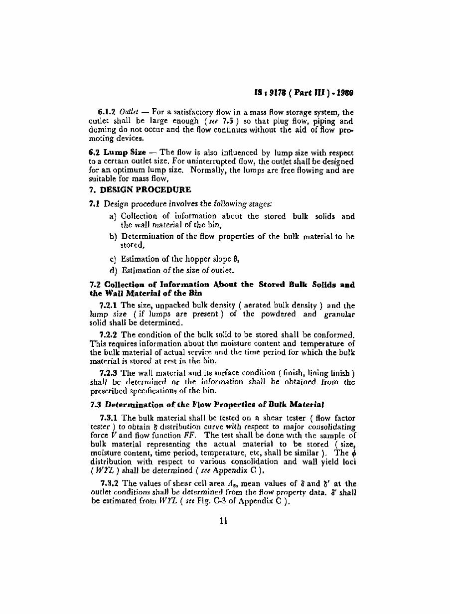
6.1.2 (hdlet - For a satisfactory flow in a mass Row storage system, theoutlet shall be large enough (see 7.5) so that plug flow, piping anddoming do not occur and the flow continues without the aid of flow promoting devices.
6.2 LUlDp Size - The flow is also influenced by lump size with respectto a certain outlet size. For uninterrupted flow, the outlet shall be designedfor an optimum lump size. Normally, the lumps are free flowing and aresuitable for mass flow.7. DESIGN PROCEDURE
7.1 Design procedure involves the following stages:
a) Collection of information about the stored bulk solids andthe wall material of the bin,
b) Determination of the flow properties of the bulk material to bestored,
c) Estimation of the hopper slope 8,d) Estimation of the size of outlet.
7.2 Collection of Information About the Stored Bulk Solids andthe Wall Material of the Bin
7.2.1 The size, unpacked bulk density ( aerated bulk density) and thelump size (if lumps are present) of the powdered and granularsolid shall be determined.
7.2.2 The condition of the bulk solid to be stored shall be conformed.This requires information about the moisture content and temperature ofthe bulk material of actual service and the time period for which the bulkmaterial is stored at rest in the bin.
7.2.3 The wall material and its surface condition ( finish, lining finish)shall be determined or the information shall be obtained from theprescribed specifications of the bin.
7.3 DeternUDatioD of the Flow Properties of Bulk Material
7.3.1 The bulk material shall be tested on a shear tester ( flow factortester) to obtain It distribution curve with respect to major consolidatingforce V and flow function FF. The test shall be done With the sample ofbulk material representing the actual material to be stored (size,moisture content, time period, temperature, etc, shall be similar). The r/Jdistribution with respect to various consolidation and wall yield loci(wri ) shall be determined ( see Appendix C).
7.3.2 The values of shear cell area AB, mean values of aand a' at theoutlet conditions shall be determined from the flow property data. ~' shallbe estimated from WYL ( see Fig. C-3 of Appendix C ).
11

IS *9178 ( Part III) • 1980
7.4 E.timation of Hopper Slope Angle 9
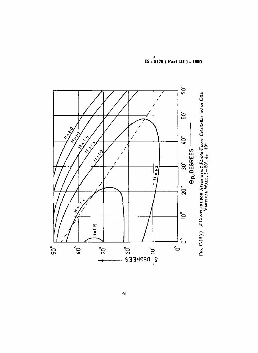
7.'1.1 Flow factor (.fJ) corresponding to the assumed 8 and 8' valuesat outlet shall be estimated from the.fJ contours for conical and plane flowchannel ( see Fig. C-1S to C-15 of Appendix C). Thelf values should beso selected that the point ( &', 0 ) IS very close to the extreme boundary.
7....2 e, shall be selected from Fig. C-B of Appendix C such that thepoint ( 0" 8' ) lies 5~ within the boundary of the selectedff for the case ofconical flow.
1....3 I n the case of plane flow channels, 0]. shall be selected very closeto the left of the dotted extreme boundary. In the case of a smooth transition zone ( transition from vertical portion of storage equipment to thehopper) with a radius of curvature Rt ;> d13, OJ' may be increased by 5°from the optimum value selected earher.
7.5 Estimation of Outlet Size
7.5.1 The estimated flow factor if (see 7....1) shall now be plottedagainst flow function FF of the bulk solid FF is a plot of V and F withVas abscissa and F a~ ordrnate, whereas if is the plot of Vand V with Vas ordinate, scale of (' and F being same for the plot.
7.5.2 II ( 6 ) corresponduig to the estimated 6 for the selected shape ofoutlet IS determined from FJ!j C-12 of Appendix C.
7.5.3 If there is no intersection of.f! with FF, and FF lies below if, itshows that the material stored IS free flowing and any dimension of outletbased on the rate of discharge and lump size shall be sufficient. An outletsize bo = G ;~ (m.lximum lump xiz e ] or the size based on dischargewhichever IS greater shall be selected. The following relation yields thevalue of [' at the outlet condition:
V ~ ~o_w A~- H (0)
When r so determined is located on .fJline, V at the outlet is alsoobtained.
7.5.4 If FF lies above jJ, it means that the solid will not flow in achannel w.th flow factor assumed. lflower values ofJfare available andif an intersection can be obtained, the new flow factor jf shall be selected.Based on this modified.o; the intersection point ( V, V ) is noted.
7.5.5 If there is an intersection of ffwith FF, it shows that the bin of aparticular slope an~ outlet size can be desisned for mass flow, The inter-section point ( V, r ) is noted. e

IS : 9178 ( Part III ) • 1980
7.5.6 After plotting If over FFo and FF, if It I~ found that lhe,fflinelies between FF0 and FFt , that 1~, JrIS above FF0 hut below FFt • the storedmaterial shows a tendency of consolidation wit h time. In these cases,vibrators are specified, so rhat the flow may be started, and the outlet isdesigned with a factor of safety to allow for any unfavourable effect of~ibration. This shall be accomplished by so selecting V that at outletV = 1'5 F.
7.5.7 From 7.5.3 to 7.5.6 according to tile case f.tced in design V shallbe selected and H (0) shall be revalued from Frg, C·12 of Appendix Cif any modification in 11 has been done dunng the location of ( V, V).
7.5.8 Minimum outlet di rnensrons, ho shall be calculated from thefollowing formula'
bo=_~,-H(Ot.r, w
7.6 Check for Estimated Design Data
7.6.1 Corresponding \0 the I' value obtained under 7.5.3 to 7.5.6,S shall bc read from plot 0 and I', This v.iluc of Swill determine the EYLof the stored rnass at outlet conditions.
7.6.2 The Mohr's semicircle shall be drawn through ( V, 0 ) such thatit shall be tangential to ElL The WYL shall then be drawn over thisMohr's semicircle. The point of iniersecuon shall determine 8' at outlet.This should check with the estimated 0',
7.6.3 If the estimated 0' does not tally WIth the check value of 5', afurther estimation offf and 0' shall be done, so that the check value of 0'is dosdy reached.
7.7 Recalculation for Slope of Hopper and Outlet Size on Basis ofCorrected Data
7.7.1 The corrected values ofjJ, 0 and o' shall be noted and the correspending 11 ( hopper slope) shall be obtamed from Fig C-13 to C-15 ofAppendix C. H ( ll) shall be obtained from Fig C-12 of Appendix C.V is obtained 111 the manner shown under 7.5.3 to 7.5.6. The outlet sizebo shall then be obtained according to 7.5.3.
7.7.2 A check is done once again to ascertain the recalculated values ina similar way as shown in 7.6.1,7.6.2 and 7.6.3
7.7.3 The check and recalculation shall be continued until correctedand check values of o' are equal.
13

IS: 91'78 ( Part III ) • 1980
7.8 Adopted Values of Outlet Size aod Slope of Hopper for Design
7.8.1 The hopper slope angle shall be equal to or less than thecalculated values It shall not exceed the calculated value in any case.
7.8.2 In the case of conical hoppers or steep pyramidal hoppers, theoutlet shall be circular or square. The diameter of the circular outlet orthe side of the square outlet shall not be less than the calculated minimumdimension boo
7.8.3 In the case of plane flow hopper, the outlet shall be rectangularor full slot. In the case of rectangular opening, the small side shall notbe less than bo Incase the stored solid contains lumps, the smaller sideshall be atleast four times ( preferably silt times) the maximum lump size.The greater side of the rectangular outlet shall not be less than threetimes the smaller Side. In the case of full slot opening, the width of opening shall be greater than the calculated boo For lumpy stored solid, it shallalways be more than four times (preferably six times) the maximumlump size. The length of slot shall be at least six times the width of slot(lo>6bo l .
7.8.4 A recommended calculation sheet is given in Appendix D for thedesign of bins for mass flow, including determination of outlet size andslope of hopper.
SECTION 3 DESIGN FOR FUNNEL OR PLUG FLOW
8. GENERAL
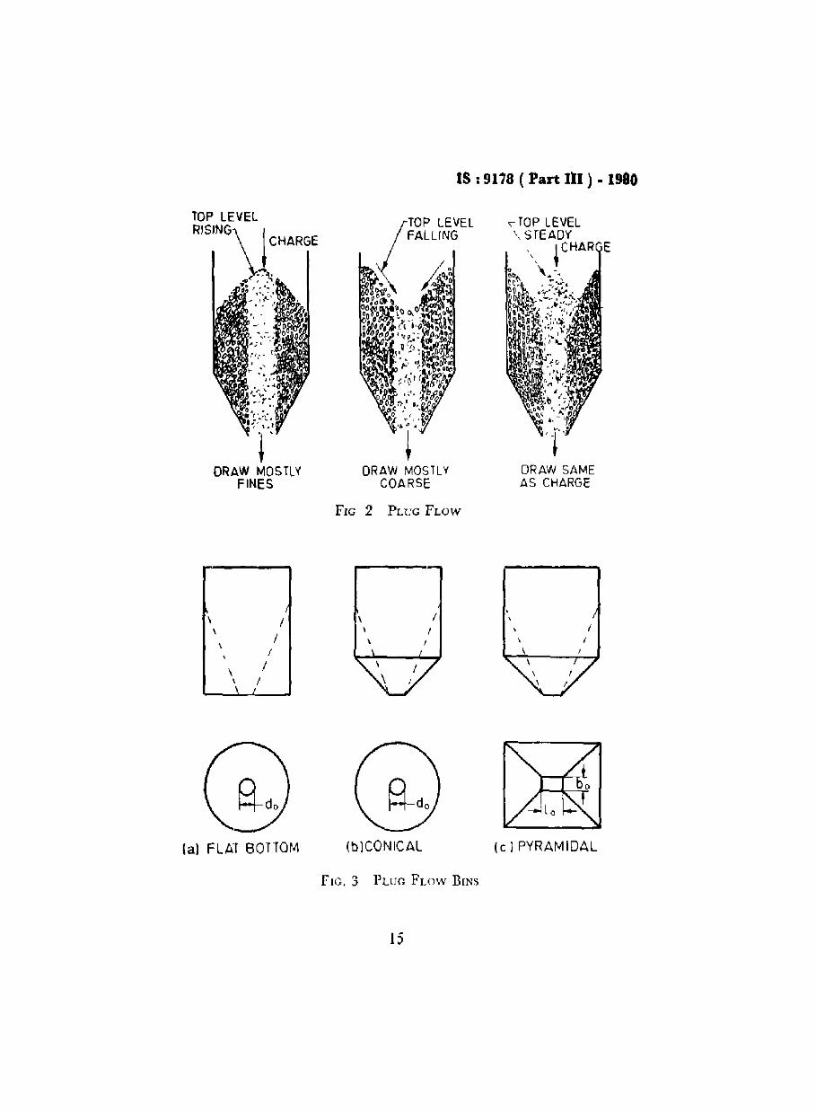
8.1 In funnel flow ( plug flow). the hulk solid flows towards the outlet ofthe bin in a channel formed within the mass, while the mass around thechannel remains stationary ( see Fig. 2). It is a gravity flow without anyflow promoting devices.
8.2 Funnel flow bins are used for storage when segregation is unimportantand there is no problem of deteriorauon with time of the stored material.Since there is httle wear in the hopper walls during service, this storagesystem is useful for the storage of hard, abrasive and lumpy solids.
8.3 Funnel flow bins ( Fig. 3) may be classified in the following types:a) Flat, bottom bins without hopper,b) Bins with conical hopper, orc) Bins with pyramidal hopper.
8.4 The shape of the outlet may be circular, square or rectangular.
14
IS: 9178 ( Part III ) • 1980
DRAW MOSTL¥COARSE
DRAW SAMEAS CHARGE
FIG 2 PLUG FLOW
\ I \ I\ \ I I
I \ I II
\ I
"/
la) FLAT BOTTOM lblCQNICAL (e 1PYRAMIDAL
FIG. 3 PLUG FLOW BINS
15

IS I 9178 ( Part III ) - 1980
9. FACTORS INFLUENCING DESIGN
9.1 Flow Properties of Stored Bulk Solid - The flow properties ofbulk solids stored in the bm is the principal factor affecting the design.These properties shall be determined under similar conditions of the bulkmass as It is stored in and delivered by the bin being designed.The factors affecting the flow properties are as follows:
a) Particle size and shape,
b) Bulk density and consolidation,
c) Moisture conient,
d) Temperature,
e) Surface finish of bin walls,
f) Time period of storage.
The flow proper\les thus determined will help in arriving at theoutlet size, the slope 01 hopper and the load distribution on the walls ofthe bin.
9.1.1 Outle: - For a sausfactory flow in funnel flow bins, the outletshall be large enough so that pipmg and doming do not occur and theflow continues WIthout any 110w promoting device.
9.1.2 Slope oj Hopper - The hopper slope shall be so selected that themoving channel 01 the mass attains a maximum possible size and there IS
no possibihty of plpmg and doming.
9.2 Lump Si:,;e - The flow is also influenced by lump size with respect10 a certain outlet size. For uninterrupted flow, the outlet shall bedesigned for an optimum lump size.
10. DESIGN PROCEDURE
10.1 Collection of Information about the Stored Bulk Material andWall Material of the Bin
10.1.1 The size, aerated bulk density and packed bulk density of thepowdered and granular solid shall be determined. The lump size ( iflumps are present) shall also be determined.
10.1.2 The condiuon of the bulk solid to be stored shan be confirmed.This requires information about the moisture content and temperatureof the bulk material at actual service and the time period for which thebulk material is stored at rest in the bin.
10.1.3 The bin wall material and its surface condition (finish, liningfinish) shall be determined or the mfnrmauon shall be obtained from thespecification sheet of the bin.
16
IS 19178 (tart ttl) .1...
10.2 Determination of the Flow Properties of Bulk Material
10.2.1 The bulk material shall be tested on a shear tester ( flow factortester) to obtain 1\ distribution curve with respect to major consolidatingforce, V, and flow function FF. These tests shall be conducted with thesample of bulk material representing the actual material to be stored(size, moisture content, time period, temperature, etc, shall be similar).The r/l distribution with respect to various consolidation shall also bedetermined (see Appendix C ).
10.2.2 The values for shear cell area As, mean values of 8 and r/l shallbe determined from the flow property data.
10.3 Determination of Hopper Slope Angle .p10.3.1 Flow factor (ff) corresponding to the average 8 and <p shall be
fixed with reference to Fig. C-9 of Appendix C. The value offfshall notbe less than 1'7.
10.3.2 Referring to Fig C-IO, the hopper slope may be fixed corresponding to the average 1\ and the ifobtained under 10.3.1. The maximum9 values for conical and plane flow channels shown in Fig. C-IO ofAppendix C shall not be exceeded If doming is to be avoided.
10.3.3 In the case of plane flow (rectangular outlet) hoppers, theslope 91l shall always be more than 30", If 1\ is greater than 40", whichrepresents the rnajonty of bulk solids. In the case of pyramidal hoppers,the slope angle refers to the valley angle.
10.3.4 The conical channels for plug flow are usually very steep andthis leads to the adoption of flat bottom bins 10 place of a conicalchannel.
10.4 DeterlDination of Outlet Size
10.4.1 The flow factor ff determined as per 10.3.1 IS plotted against theflow function FF of the bulk material. FF is a plot of V and F with Vasabscissa and F as ordinate, whereas ff is the plot of V and V with Vasordinate, scale of V and F being the same. The Intersection ofifwith FFyields a point ( V, V).
10.4.2 Functions G ( .p) and H ( a) are evaluated from Fig. C-II andFig. C.12 respectively of Appendix C.
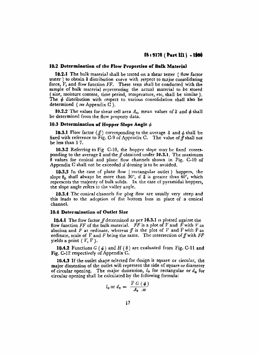
10.4.3 If the outlet shape selected for design is square or circular, themajor dimension of the outlet will represent the side of square or diameterof circular opening. The major dimension, 10 for rectangular or do forcircular opening shall be calculated by the following formula:
10 or do =VG(.p)
A•.w

IS ,9178 (Part III ) ·1980
10.4.4 If the outlet is rectangular in shape, the minor dimension bo ofthe outlet ( apart from the major dimension 10 ) shall be obtained to avoidany doming. bo is calculated by the following relation:
bo
= V H (6)As. w
10.4.5 The dimension of the rectangular outlet is given by bo X 10 ,
The dimension 10 shall be so adopted that is always greater than threetimes boo
10.5 Adopted Valaes of Outlet Size aDd Slope of Hopper
10.5.1 Adopted values for the outlet dimensions shall be larger thanthe calculated values to accommodate the uninterrupted flow of lumpsalso. The dimenslon of outlet shall be at least sill: times the diameter of thesize of lump being handled.
la.5.2 Adopted slope of the hopper shall be equal to or smaller thanthe calculated value. It shall not exceed the calculated value in any case.
10.6 A recommended calculation sheet is given in Appendix E for thedesign of bin for funnel flow.
SECTION 4 LOAD DISTRIBUTION FOR DESIGNOF BULK STORAGE BINS
11. INITIAL AND FLOW PRESSURES
11.1 The method of calculation is based on the principle of minimumrecoverable strain energy (For full details of the concept and pressuredistribution, reference may be made to the papers • Bin Loads Part IIconcepts; Part £II - Mass flow bins and Part IV - Funnel flow bins' byA. W. lemke,]. R. Johansen and] W. Carson, published In tne Journalof Engineering for Industry of ASME, February 1978 ). There are certainlimitations of this theory as pointed out by different research workerswhich are outlined in Appendix A. The procedure for determiningpressure distribution as given in this section may be adopted subject tothese limitations. The loads which act on the bin walls are different during the initial stage of charge into a bin and during the flow stage from abin, because the deformations which the stored materials undergo duringthese two stages are different. In the initial stage when the bulk materialis charged into an empty bin with the discharge gate closed or the feederat rest, the bulk material settles down as the head of bulk material rises.During this process, the material contracts vertically in ,the cylinder asalso in the hopper. The major pressure tends to align with the directionof contraction of the bulk material. Hence. these initial pressures are closeto vertical throughout the bin thus forming a .. peaked II pressure field.
18

IS t 9178 ( Part III ) • 1980
This initial pressure corresponds to load calculated by Janssen's methodin the cylindrical part of the bin and by a linear distribution inthe hopper. This assumes that the bulk materials are not charged withsignificant impact and the bulk storage materials in powder form arecharged at sufficiently low rate so that they deaerate. If granular bulkmaterials are to be dropped from some height the bins have to bedesigned with safety for impact and wear in impact areas. Powderymaterial when charged at high rate may develop close liquid pressures onthe walls. Also, it should be ensured that the storage materials are suffi.ciently free flowing without obstruction; otherwise, stable arches of thestored materials may form. When this arch collapses, a large amount ofbulk material falls and induces dynamic loads in the bin.11.2 When the gate is open or the feeder is started, the stored materialstarts flowing out to the outlet, and in this case, a vertical expansion ofsolid takes place within the flow channel. The minor pressures may tendto align with the direction of expansion of the stored material. As a rule,the flow channel diverges upwards from the outlet. Hence, the flawingmass of stored material also contracts laterally. The major pressures with.in the flow channels tend to align with the lateral contractions. Hence,major pressures are essentially lateral, minor ones are vertical and thepressure field is arched.11.3 The region of switch from peaked to arched fields originates at theoutlet of the bin when the gate is first opened or the feeder is slarted andrapidly travels upwards into the bin as the stored material is withdrawnfrom the bin. At the level of the switch, the equilibrium of the massimposes a sharp overpressure on the walls of the flow channels. Thisoverpressure travels upward with the switch at least to the level at whichthe channel intersects the cylindrical part of the bin to the level of thetransition in mass flow bins and effective transmission in the case of funnelflow bins. In a cylinder, above a transition, experimental data indicatewide oscillation of low pressure with time and this along with the peaksneed be predicted. This has been analysed as a strain energy, based onthe second law of thermodynamics and the pressure distributions for themass and funnel flow bins are worked out.11.4 The procedure for load distributions suggested in this code may beapplied to bins designed for mass and funnel flow.12. PROCEDURE FOR CALCULATION OF LOAD DISTRIBUTION
IN MASS FLOW BINS12.1 Initial Pressure
12.1.1 Cylinder - Initial pressure Ph' on the walls of cylinder is:
W R[ -~;<1]---;- l-e
19
(I)

IS r 9178 (Part 111).1980
dand the hydraulic radius R = --=---~--,----c
2(I+m)
where'
m = I for circular bin,
= 0 for long rectangular or square cylinder. and
A = 0'4.
.oo (2)
I n the cylinder, the frictional stress lw is related to normal pressurePh by
•• , (3)
... (4)
12.1.2 Hopper - The surcharge, due to the stored material in thecylinder. exerts a vertical load Qc ( see Fig, 4-) on the stored material ofthe hopper. This force becomes maximum when the cylinder wall pressureis minimum (Janssen's distribution ). This is given by
Qc wR [ =fi!!"J-:4 = ---;T I - e
Values of ~~1.- are plotted in Fig. 5.
The initial pressures perpendicular to the hopper wall are assumedto vary linearly from the apex to the transition, as shown in Fig. 4. Thevalue at the apex, Pnl is given by
P w.dOJ = 2( tan 6-+-t-an~8~h""')
The initial pressure at the transition. PnU, is given by
,.. (5)
(2 +m)( 1+ m)
tan II• tan 6 + tan 8h ... (6)
The parameter m is 0 for long edged shape hopper and 1 for conicalhopper.
The frictional stress /" is related to normal pressure Po by
I" = Po tan ll"
2J
... (7)

JS I 9J78 ( Part III ) ·1••
d
\ I /\ I\ I
"Ia
\\
\
FIG. 4 INITIAL PRESSURES IN A CONICAL HOPPER
21

II t 9171 (Part UI)· 1910
o ~----------~-.-,
I' g coooW .... N
"0"
12 20• 8
~----wR
o
8
20
I 10
I 12
'8
18
-/L >. (hIR)l-eQclA
FIG. 5 FUNCTION -"~- - -----;---wR
12.2 Flow Presaures12.2.1 Cylinder - The pressures exerted by a mass of stored material
in a cylindrical vessel are governed bya) Slight deviation in shape of the vessel from cylindrical, andb) thin stable or unstable boundary layers of solid which forms at
the wall of the cylinder.As a result, only bounds on wall pressures can be established.
Janssen's formula nearly gives the lower bound and the upper bound iscalculated by the consideration of strain energy of the mass of storedmaterial.
An example of the loci of maximum cylinder pressure computedfrom strain energy and modified for the hopper effect is plotted in nODdimensional form ( Phlwd )max in Fig. 6. These pressures are a functionof the distance from the top of cylinder and the product pl., Janssenpressures are also plotted as a reference.
22

1819178 ,PartlD ) - ••
2
IPhl .... ) m•• --_
~ SlRAIN ENER:a.,.
,...--"''': 0 '0'11\ .--_:0 15
'1' -0·201\\. ~o -olit,111 1 JANSSEN
" : '0'11\ ,4-025, of r = 0-]7'SI' . ,- '0· 50It""'" ___ =0 7$
:;: IJ
o
e
I,
jI
I
I
.1
FIG.6(a) (Phlwd lmal<' FOR CIRCULAR CYLINDERS, hId = 3
0F::""------,
\ ............................_----'o )
IP"lwd) I'r\U-----
JANSSE~
)."-"0
)1,0 25,0 315·0·50'0·15
STQAI~ ENUGl
}.lA,o 10.0 15: 0 20: 0 )0
"d
rFrG. 6(b) (Phlwd )wu. FOR CIRCULAR CYLINDERS, hId = 5
The vertical force Pw caused by the frictional stress twPh is computed from
Pw [ p.., ] wdS
red = (" W.dB 1 mal< X -;-
Ty pical results in non-dimensional form ( Pdw_)W a WBJ;
ted in Fig. 7 for circular cylinders,
and Pressure
.. , (8)
are represen-
23

ol
i
l e;; - .- ... ~ • i-6
AS
,ED
ON
ST
RA
INE
NE
RG
V
~a(
I
•
,I 1'
•
/J.A
=Q
·30
~=OI5
~=o,o
23
(I'w
fWd
3)rn..
__
__
BA
SE
Da
NS
IRA
'N(N(IlG~
),
",
'o
z1 1.
, ,
\
N A.
•3
12
(F't
N/W
d),
mil
l(,
5'
,'
,l
oI
\
FlO
.7
(a)
{P
"/w
dS
)ma,
,.F
OR
CIR
CU
LA
RC
YL
IND
ER
Sh
/d=
3F
IG.
7(b
)(P
wfw
d8)m
a".
FO
RC
IRC
UL
AR
CY
LIN
DE
RS
hjd
=5

IS 19178 ( Part III ) .1980
12.2.2 Hopper - Flow pressure variation in a mass /low hopper consistsof a pressure peak at the transition, then a lmear decrease to anintermediate value and another linear decrease to zero at the apex( see Fig. 8 ).
o Po
FlO. 8 FLOW PRESSURE IN A CONICAL HOPPER
12.2.2.1 The radial pressure component at the transition PII~r isgiven by
Pllt r = ( :B ).w.ri. ••• (9)
Typical plots of ( :B ) as a function of eand 8h are given in Fig. 9
and Fig. 10 for conical channels and symmetric plane flow channelsrespectively.
25

JI.9178 ( Part III ) .1980
•20· 30·
et •DEGREES ----
10·
30·,...--~....---....---....,...--....,..--......,..----.I 0 01•••,.,
~ 20k==~~--J....LIJJ0::eo •~ 10s:
<0
f1FIG. '1( a) wE CONTOURS FOR CONICAL CHANNELS, B= 30·
•20· 30·
at.DEGREES ---0-
1,0'
t 30·lflWwn::l:l 20·w s:0 wB 2·0.s:
<0
10·
FlO. 9(b)awB CONTOURS FOR CONICAL CHANNELS, 3 = 40·

IS I 91 '18 ( PBl"t til ) • 1980
•20· 30·
ee.DEGREES----
•10
•40 Plr--.,.--.....,..---,.-----,---..,
r 30 ~~~~~t--__+_--t--_1If)w\oj
a: •l:3 20 ~-"x-oL.
10
FIG.9(c) :B CONTOURS FOR ComCAL CHANNEL', 3 = 500
..40· 50·20· 30·
Se,DEGREES ---
10'
40·
I •)0lfIuJuJa:~
200
w0 ,.J::
<0
~~20010·
L=3·0wB
o'a·
FIG, 9(d)(J
CONTOURS FOR CONICAL CHANNE.Ls, 11 = 60·wB
27

IS I 9178 ( Part III ) • 1!18O
so' ,----,------,-.----r---"""T'"--.....,
50'
-20· 30·
Sc.OEGREE5 ----
10·&=20
!s-'>] 0
I"o·
30·IIIIIJIIJQ:C)
20'w0•.c
co
10'
"" loS'min VAlUE:
SOO
<,<,
",'0 ),39
r1!-'IO. 9(e) - wB- CONTOUR~ FOR CONICAL CHANNELS, a= 70°
30°nl"'~:-r-,,::;:;:>,........,r-~T"'""'I---n--"""T--"""
t 0c=~4~r--=f:~~~H1/)20UJ ,....._~
~ 1-'::""'-1
h1 0
o.lo'k-=~~~--+---=:::::t:=-~j...L~-ls:
IC
..t!
FlO. 10(a) wB CONTOURS FOR SYMMETRIC PLANE FLOW CHANNELS. ~ = 300
28
Is I 9178 ( t-art 111 ) • Ill"
1/1
~ 20° po~--+-.=........,n::ao
50° 60·
-8 p.DEGREES -----
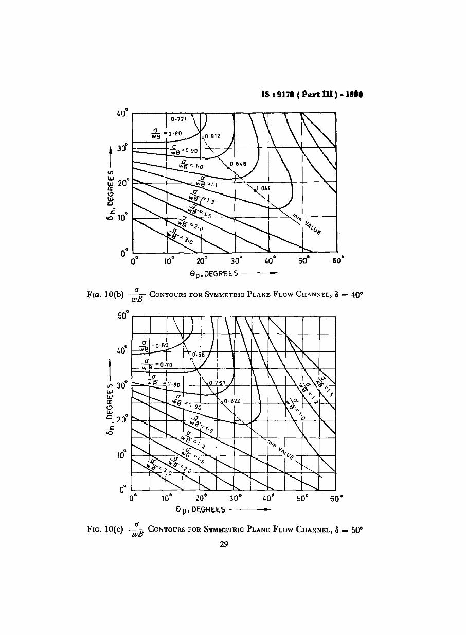
aFlO. 10(b) wE CONTOURS FOR SYMMETRIC PLANE FLOW CHANNEL, Il = 40°
50°
•10° 20· 30·
8 p.DEGREES -----
(1FIG. lO(c) wE COr-.TOURS FOR SYMME1RIC PLANE FLOW CHANNEL, Ii = 50·
29

IS • 9178 ( Part 10 ) • 1980
60· ,....---...,....--r"""'T............,.-,,'It""""--...,....---;-----,
so· I-----l-----,I---++------\---\-t\---\--\-~---t----t
!40·
-.SL....e =0·'0
oJ) 30·wWIXC)WQ
20·..J::
10
10·
10° 20° 30° 40°Sp DEGREES -
11FIO.lO(d) wB CONTOURS FOR SYMMETRIC PLANE FLOWCIIANNEL, 3 = 61.,0
30

IS: 9178 ( Part III ) • 1918
600
-"- ~f05
1
~~O4wB I
wB CJ
500 W"lr~12
'"UJ
"if w~ "'01WQ:C>UJ0 .s:
300
<0
ep,DEGREES ..
rtFIG. 10(e) wB CONTOURS FOR SYMMETRIC PLANE FLOW CHANNEL, a= 70~
17.2.2.2 The peak pressure Pnt can be calculated from
33 [( ~c - ~)"'. P r • Wod.J( 2 -- 004 sin II ) m ( sin II + cos 0 + tan ISh )
31
••• (10)

III 9178 ( Part III ) ~ 1988
..20· 30·8c,DEGREES---
This equation is based on the overpressure at the transition beingdistributed over 03 d of the hopper wall. The value of Qc/A is computedfrom Eq. (4). Typical plots of Pr contours are given in Fig. II andFig. 12 for conical channels and symmetric plane flow channelsrespectively.
30·~~;;;:-I-T-T-I---'
FIG. 11 ( a) Pr CONTOURS FOR CONICAL CRANNELS, 8 = 30°
I30·
III 20·llJWa:l!)w0 - 10·•<0
0°20· 30"
8c·DEGREES •
FIG ll(b) Pr CONTOURS FOR CONICAL CHANNELS, 8 = 40°
32

IS: 9178 ( Part III ) - 1980
/.,0·
1 30"IIIlJJlJJa:~
20"lJJ0 ,s:
10
10·
20°
DEGREE S •
FIG. lI(e) Pr CONTOURS FOil, CONICAL CHANNELS, 3 = 50°
60·..
20· 30·
8p,OEGREES----
30',--~---,-""""-""-"""",-""""------,,,,,,,,--_,,,,,,,,,,,,,-,
Lo~;:';>--]r,O·5:-0-+-::::......"...----1f\----+-~!oJ!oJ
~!oJ •0.10.c.10
FIG. 12(a) P, CONTOURS FOR SYMMETRIC PLANE-FLOW CHANNELS, 3 = 30·
33

IS I 9J18 ( Part in ). J980
-10° 20· 30·
ep,OEGREES----
0358o
o·
rJlW
~ 20" ~-~+--'","--';-'--~---f"-;;:--~-+--~;:t-----':~-i
:.3c
FIG. 12(b) Pr CONTOURS FOR SYMMETRIC PLANE-FLOW CHANNELS, 0=40°
50' ~--........:--_:-1'""---.::c-r_,.._........,........--;__--..,
40·
t 30·rJlUIUI0::I!)
20·w0 .s:
ItO
10"
I:q"'~(~
O· ~
O· 10' 20' JO" 40" 50' 60'8 p, DEGREES -
FIG 12(c) P, CONTOURS FOR SYMMETRIC PLANE-FLOW CHANNELS, 0=50·
34

IS: 9178 ( Part III) • 1980
12.3 Appendix F may be referred to for a typical procedure for theapplication of the above-mentioned method for calculating loaddistribution in mass flow bins
13. PROCEDURE FOR CALCULATING THE LOADDISTRIBUTION IN FUNNEL FLOW BINS
13.1 In tall funnel flow bins, the flow pressures are larger than the initialJanssen's pressure. Hence, for design purposes flow pressures have to beused. Fig. 13 shows the general bin configuration and some of the usefulvariables.
JANSSEN
o
d
r
LOCUS OFPEAK PRESSURE
OWEST LOCAl-.,-;-.- --j'ON OF
EFFECTIVETRANSITION
FIG. 13 FUNNEL FLOW BIN PRESSURES
13.'2 Cylinder - The loci of ( Pblwd)max, the maximum non-dimensionalhorizontal wall pressures exerted by a mass of stored materials on thewalls of a vertical cylinder are drawn in Fig. 14 for different hid ratios
with ~l as y-axis, These pressures are a function of the height from the
top of the cylinder and the product rA. A value of 0'4 is taken for .\.
13.2.1 The equations on the basis of which the figures for differentvalues of hid may be drawn are given in clauses 13.2.2 to 13.2.4.
NOTE - For a height to diameter ratio less than 2. It rs suggested that]an.sen'.equation may be used, for the flow channel seldom intersect. the cylmder wall.
35

IS I 9178 ( Part III ) • 1980
•
""-1/
, I
~
j
u A= 0·02"0·10wO·20"0'30
1 2 3 4
(f'h!wdl",.. -
FlO. 14(a) (Pb(wd )mox. FOR CIRCULAR CYLINDERS, hid = 2
I aII
<\ jJ.'!I:0·020 : 0'06
d =0·10=0· '5=0·20=0,30
2
124
(Ph fWd'''' I... •
FlO. 14(b) ( Pblwd )mox. FOR CIRCULAR CYLINDERS, hid = 3
)6

FIG
.14
(e)
(Ph
/wd
)m..,
,'F
OR
CIR
CU
LA
R
CY
LIN
DE
RS
,h
id=
4
.... II> (C ... ~ ..... ~ ... = - • ... ~
4
).J
A=0
02
,,0
Of;
"0
"0
=a
15
=0
·20
:....c~=0,30
41IIff
II
}r
1r
7>
(Ph
fWd
Ima
x
DK
I
(P
h!w
d)m
a".
FO
RC
IRC
UL
AR
CY
LIN
DE
RS
,h
/d=
5
2 2, -5
'rIll
//'
o'
II
I
d L
FIG
.14
(d)
d
~
IiX
,,0
·02
,,0
-06
=0
·10
"0
,15
=0
·20
=0
·30
23
~L
11
1/,
1(,
'I
o,
lPt'
/wd)
rna'
31
f(
f')
)f
jr
I
OK
I
z1 d l2
d
~
w ......

IS, 9178 ( Part III ) • 1980
13.2.2 Figure 15 shows the equilibrium at an effective transition.
Assuming that the ratio of horizontal to vertical pressure at aneffective transiuon, .\1 is equal 10 that ratio m the radial stress field, lowerin the conical channel, the peak pressure at an effective transitionis given by
uik [-e', Z. ]
PI = "1-- I -e R (ll),.,. ~g
c!
~c--"
(1- f
~;P'~' p.,
\s
0""
.: /
\ e' //,
9 \1/FlO. 15 EQUILIBRIUM AT AN EFFECTIVE TRANSITION
13.2.3 Considering the radial stress field, .\ is to be determined as givenin Eq. (12) after establishing
a) a relationship between IT and Ph, assuming that the wall of theflow channel to be a velocity characteristic, and
b) a relationship between IT and Pr :
\ = (24 tan 0' + 1r1.Pr) ( 1 - sin 8 . tan 6' ) (12)" 16 ( sin 8 + tan 6' ) ..
Value of P r and 6' as function of 8 can be determined. By taking.\ = A, PI can be calculated from Eq (11).
38

IS a9178 ( Part III ) • 1980
.•. (13)
1r .. (15)J
wdS
13.2." Frictional stresses accompany Pb and are computed from thefollowing:
tw = po Pb
These stresses cause vertical force P.., in the walls and are the sameas those worked out for mass flow bins. The vertical force per unit lengthis calculated from the equation:
r; (P..,)-- = --3--'.,. d (wd )max 1f
13.3 Hopper - The pressure field computed for the cylinder is assumedto extend into the hopper. The normal stress Pn and shear stress th onthe hopper walls are computed from the equations:
r, = Ph [Ci~2 6 + cos3 e) + 2; [l (1 ++) sin €I cosa]:
and r ... (14)
tb = Ph [(+-1 ) sill 6 cos 6 + ~r po (COS! 6 - Si~26 ) ] JThe variable r is defined in Fig. 13.
For a flat bottomed bin, the above equations reduce to:
Ph = Pb!;>'-2 rpo Pb
tb = --dA
13.4 Reference may be made to Appendix G for a typical procedure forthe application of the aforernenucned method for calculating loaddistribuuon in funnel-flow bins.
APPENDIX A( Clause 0.6 )
LIMITATION OF jENIKE'S THEORY
A-I. Experimental evidence reveals overdesign of the cntical outletwidths 11l mass flow hoppers when the standard Jenike's method isfollowed (1)*. This IS due to the fact that Jellike does not account forthe possibility that an arch across the outlet may slide along the wall (2)and for the fact that the arch in addition to its own weight will have tosustain the weight of the powder above.
*i'iIumber III paranthesis refer to the luerature given m 0.8.
39
IS .9178 ( Part III ) .1980
A-2. Arching just below the transition is frequently reported (3). Thisdoes not seem ro cover that.
A-3. Actual stresses close to the transition zone between parallel part ofthe silo and the hopper section deviate strongly from those predicted bythe radial theory (1).
A-4. It does not adequately allow for the impact loading which oftenoccurs on filling and can easily cause arching (3). This is believed to be amajor reason for the discontinuity of flow that commonly occurs inbunkers designed based on ]enike's method.
A·5. Jenike's shear cell which is the main tool in finding out the designparameters of the bulk materials used in this theory ( which has beendescribed in Appendix A of the draft code) could be used only in thecase of samples with particles top size of only about 1-6 mm and issubjected to the foHowing Jimuations (4).
A.5.1 The limited shear displacement available makes necessary a ratherarbitrary and laborious preparation of the sample prior to the shearconsolidation.
A·5.2 To obtain design data for hoppers with outlets less than about1 metre across requires knowledge of material characteristics at majorprincipal stresses of less than 70 kgjm2 . At the low normal loads requiredfor this, llftinR or pivoting of the cell lid, assocrated with non-uniformstress distribuuon becomes nouccable.
A.S.3 The tensrle strength of material may be measured in the annularshear celI designed by Walker and Carr (5) instead of a split Jenike-typeceU as recommended by Ashton, Farley and Valentin (6).
A.S.4 Professor Schwedes (7) points out that in the flow factor tester ofJenike, the state of stress cannot be determmed completely and assumpnons regarding the positions of slip planes are necessary to evaluate thetest results.
A.G. Other research work has been in progress and the relevant referencesare included (8).Conclusions: The theories presented by Walkar (9), Walkers (10.12) and
Enstad (I) are meant to cover the limitations of Jemke'stheory but they are approximate a fact also pointed out bythe authors themselves.
Reference to the work done by Docksen (I3) may bemade for the precautions that have to be observed whiledesigning the bIDS.
40
IS : 911& ( l'art til ) . 1980
APPENDIX B
( Clause 0.9 )
RECOMMENDED LITERATURE FOR REFERENCE
1. Enstad 'On the theory ofarching in mass flow hoppers' Chemical Engineering SCience, 1975, Vol. 30,pp. 1273-1283.
2. Molerus, a and ' AuslegungsdiagrammeSchoneborn, Chemie-Ing-Techn, Ed.P. R. S.741/45.
fur Schuttgutbunker "43 (1971), Nr. 13,
3.
4.
6.
7.
8.
9.
10.
Wright, H.
Walker, D. M.
Carr,]. F.and Walker,D.M.
Ashton, M. D.Farely, R. &ValenunF.H.H.
Schwedes, J.
Proposed, ACIStandard
Walker, D. M
Walters, J. K
• An evaluation of the ]enike Bunker designMethod' Transactions of ASME, Journal of Engg.for Industry, Feb. 1973, pp. 4B-54.
•A basis for unker design', Powder Technology,1 ( 1967), pp. 228-236.
I An annular shear celt for granular materials',Powder Technology, I (19b7/6B), pp. 369-373.
, An improved apparatus for measuring the tensilestrength of powders'; ]ournal of Scienufic Instrument41 ( 1961 ), pp 763-755.
, Measui ement of powder properties for HopperDesign', Trans. of ASME, Journal of Ep.gg. forindustry, Feb. 1~73, pp. 55·59
'Commentary on Recommended Practice forDesign and Construction of Concrete Bins,Silos and Bunkers for Storing Granular MaterialsACI Journal, Title No. 72-38, pp. 550, Oct. IY75.
, An approximate theory for pressures and archingin hoppers' Chemical Engineering Science, 1966,21, pg. 975.
'A theoretical analysis of stresses in silos withvertical walls', Chemical Engineering Science,Bd. 2B ( 1973), NT I, pp. 13-21.
41

18 J 91'78 ( Part DI ) .1980
11. Walters, J. K. • A theoretical analysis of stresses in axiallysymmetric hoppers and bunkers; Chemical EngineeringScience, Bd. 28 ( 1973 ) Nr. 3, pp. 779/89.
12. Walters, J. K. • A note on the stress distribution at great depth inand Neederman, silo', Chemical Engineering Science, Vol. 28R. M. ( 1973) Nr. 5, pp. 1907/8.
13. Doeksen, G. • Precautions in order to attain design capabilitiesor Mass-flow system', Journal of Engineering forIndustry, Transactions of ASME, Feb. 1973;pp.93-96.Bunker Design-Transactions of ASME Journal ofEngmeering for Industries November 1977 byAmerical Society or Mechanical Engineers ( Pages809 to 827 )Part I Bunker outlet design and initial measure
ment of wall pressures by PC RichardsPart II Wall pressure in mass flowPart III Wall pressure and flow patterns in funnel
flow
Part IV Recommendations
APPENDIX C( Clause 7.3.1 )
PROCEDURE FOR TESTING OF FLOW PROPERTIESOF BULK SOLIDS
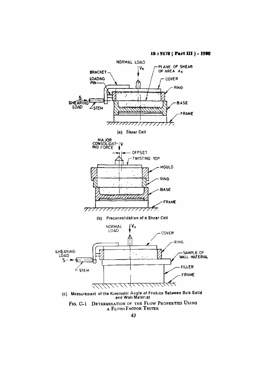
Col. The tests for determination of flow properties are performed on theflow factor tester which consists or a shear cell with cover and arrangement for applying normal and shearing load on the sample packed in theshear cell. The normal load is applied through the hanger and weightsand the shearing load is applied gradually by an advancing screw stemoperated by electric motor, causing a stem displacement of 0'9 mm/min,The shear load is measured by a proving ring placed between the screwstem and shear cell [see Fig. C-I (a)].
The inside diameter or shear cell is 63 mm, and the height is 38 mm,which yields the shear cell area,
A. = 0 003 12 m 2
42
15 I 9178 I Part III ) • 1910
NORMAL LOADPl ANE OF SHEAROF AREA As
SHEA~lfrG=.;;;::;:::;=-n- 'f~-~4+-L_..........4I..LOAD
RING
BASE
FRAME
/
(a) Shear Cell
MAJORCDNSOLIDAT-I VING FORCE ,
MOULD
RING
BASE
FRAME
(b) Preconsolidation of a Shear Cell
FILLER
FRAME
SAMPLE OFWALL MATERIAL
NORMALLOAD
/COVER
~:::;==l---l+l-----L~ RING
-,
L STEM
SHEARING
LOAD ~~HS- u::: J4l -\-_--'-_----.J.u-----,
(c) Measurement of the Kinematic Angle of Friction Between Bulk Solidand Wall Material
FIG. C.l DETERMINATION OF THE FLOW PROPERTIES USING
A FLOW- FACTOR TESTER
43

III 9178 ( Part DI ) • 1t80
C-l.l Shear cell which is the main tool in finding out the design parameters of the bulk materials used in this theory could be used only in thecase of samples with particle top size of I 6 mm,
C-2. Bulk density of the aerated bulk material is determined without anypacking. Thereafter, the bulk densities of packed bulk solids shall berecorded as further tests proceed under various consolidating loads.Typical curves giving bulk density at different consolidating loadsare given in Fig. C-2 for gypsum, trlple superphosphate and pulverisedcoal. Similar curves should be drawn for the material to be stored.
C-3. The bulk solid to be tested is placed in the cell set-up shown inFIg. Col (b) for preconsolidation One layer after another is packed up tothe top of the mould and excess material is scraped off. The twisting topis placed over the packed solid. A normal load is applied on the top withthe help of hanger and weights. A number of oscillating twists areapplied to the top by means of a special wrench. This completes thepreconsolidation.
C·4. The load applied for preconsolidation is removed and the twistingtop and the mould is removed with precaution SI) that the base and ringof the shear cell are not disturbed. The excess material over the ring isscraped ofT lever with the top of ring. The test cover is placed over thematerial and the consolidation load is applied to the cover. The screwstem ( shearing device) is advanced against the bracket so that the shearof the laver of material starts. The shear load attains a steady maximumvalue for a certain consolidation normal load. This completes theconsolidation and shear yielding of the bulk solid. The values of normalloads and shear load are recorded.
C-5. The shearing of the material is done at various normal loads underthe same consolidation. This is done by consolidating the test samplefollowing the same procedure as under C-'\- shearing until 95 percent ofthe maximum shearing force as obtained under C-4 is reached. At thispoint, the normal consolidation load is replaced by smaller normal loadsfor further shearing of the sample. The maximum steady shear forcevalues thus obtained shall be recorded.
C-6. Yield locus shall be plotted by locating various normal loadsvs shear load values for a particular consolidation load. A number ofsuitable consolidation loads selected shall yield a family of yield loci.Mohr's circles, when drawn, yield major consolidating force V andunconfined yield force, F. These plots shall also give kinematic angle ofinternal friction and effective angle of friction of the bulk solid.
C-7. Plots of Wall Yield Locus - The shear cell shall be arranged asshown in Fig. Col (c). The sample of wall material is placed as the base,representing the actual material and surface condition of the bin
44

IS , 9178 ( Part IU ) • 1980
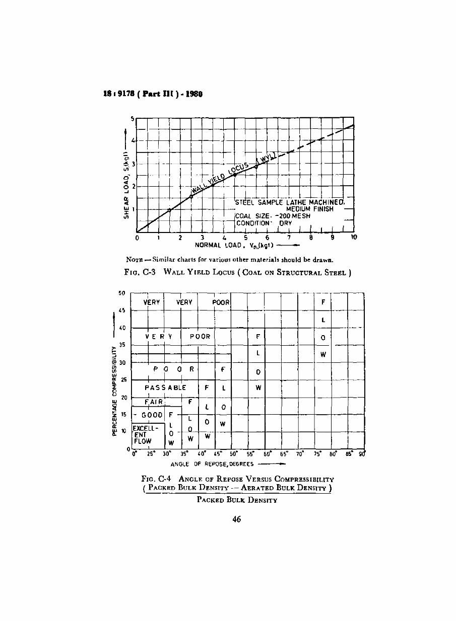
or hopper wall. The bulk material is placed inside the ring up to the top.The cover is placed and normal load IS applied on the cover. The maximum steady shearing forces are recorded for varrous normal loads yieldingthe points on wall yield locus (WrL). A typical WrL for coal onstructural steel is plotted in Fig C-3.
C-.8. The charts and curves given in Fig. C-2 to C-IS are based on thetests explained in this appendix and they apply for typical bulk solids.They are given for information only. Such data should be worked outfor each of the stored materials for which the Inns are to be designed.
1500
1400
1300
1200
, IlOO
"'eOr1000""~.>' 900....Ulz BOO\l.lo
700~
---'
ffi 600
500
IA j JJ l.l. 10
ROUND SIZEl-200MESH1DRhG'iPSUMIG· I_
e
1/
TSPIPOWDER.$IZE 1-35MESHIMOI5TURE 3
V~e
\7~-j
I Ii
COAL I PULVERISED SIZE 1-20uMt:SH}. DRY I,
1
---~ I
/
°101
400o 20 40 60 80 100 120 140
CONSOLIDATING LOAD, V, kgl _
[60
NOTE - To convert consolidating load to consolldanng pressure (kgr/cm')divide by 3 t-20.
FIG. C-2 CONSOLIDATING LOAD VERSUS BULK DENSITY CURVES FOR
GYPSUM, TRIPLE SUPERPHOSPHATE AND PVLVERISED COAL
45
1819178 ( Part II[ ) ·1980
f0- oL
... ",.,-
"",.~
'l!~~---
\.o9:l~
l.-L~~~- ~V .
f-- fo- f--- -I ~ .....
./V sn EL SAMPLE LATHE MA(,HINED•
VMEDIUM FINISH -
COAL SIZE. -200 MESH
t> CO,NDI;'O~' lOR; I I I I r-7o 2 3 4 S 6
NORMAL lOAD, Vn.(J... t) ---8 9 10
NOT~ - Similar charts for various other materials should be drawn.
Flo. C-3 WALL YIELD Locus ( COAL ON STRUCTURAL STEEL)
V~RY VkRYI
.
POOR F
l
V E R V POOR F 0
L W
I P P a R f 0I
PASSABLE F l WI
FAIR F. L 0r- GOOD F
lL 0 W
EXCElL- oENT 0 WFlOW W
W0
0,
,2S' )0' )S· '0' '5" 50' ss" 60' 65" 10' 15' 80' 85" 9
so
>- 35....:;iii 30
~w'" 25
~ 20
~~ 15
l' 10
ANGLE OF REPOSE. DEGREES ~---
FlO. G-4 ANGLE OF REPOSE VERSUS COMPRESSIBILITY
( PACKED BULK DENSITY - AERATED BULK DENSITY)
PACKED BULK DENSITY
46

IS I 9178 (Part m).1910
..bdo :l<>/t \)y 'v~;
Q "? ~"lY' h_ ~~.. ~'=' ~o/~ !>cO .'L/
/ ,~:2l ~~~vi/ ,,~ ;' ~ -tft'
-If' 1/...
E-- - -/:/ -,-1---
en I-" - ---r/'(j- ,,~"D-----1---_ "D\S~-
f/l f~
.J vtz e-----z0 ..~ 170 ,
7 t-/ FF -DRY SAND0
o Po
CONSOLIDATING FORCE, V, kgt-
FIG. C-5 SOLID FLoW FUNCTION FF AND HOPPER FLOW FACTORfj
,w...llI:o...'"<w:rIII
,01'E.51 VE
, _o~ C.,~ 1
~"/V e.~V .I'~
/ ./ \'II'."'~VcO ~1.0'll",\"
V e.~e.j~... ;:!.'i<' ...../ ,//~
~VNORMAL LOAD, Vn---
FIG. C-6 TYPICAL YIELD LOCI FOR FOUR CLASSES OF POWDER
47

HO
PP
ER
SL
OP
EA
NG
LE
,8
.D
EG
RE
ES
-
-1A ~ ... -.J • • i:P :l - =- -
'I-l
•....
.......
UN
GE
"",
OF
"LA
NE
.f'-
FLO
W
'\,
l--
1"-..
I-
Ir-
,
~I'
-"
, I r r-,
r<
,
-,'"
hN
GE
"'"
IO
FIr
-t'--
-CON
IC/I
.l"-
FLO
W
•"'"
,
"'\l
'!'-...
",
os o
•O
·1
0·
20
0]0
04
0,"
,OP
PE
RS
1.0P
EA
NG
LE
>6
.D
EG
RE
ES
..
o :; gIt,6 ~
)0"'"
,....
..~~
]0"'"
,oi
l..
.
ZO
.O.
00
I;=
•~;C
:011
...~
sCi
o....
....... <3;
~z "0
u:t
II=
..)0
.. ::I ... z_
i]0
4.0·
)02
010
O·
I:J
.
•,~,
I .~
1"-..
.,.
)
~fc
UN
NfL
FlJ
)W
;r-
, <,
•M
AS
SF
l0
W""-.
) • ).
_.-
.0
.
20"
30
•s 40
o ",If)
",,
,,0
'"_
II:
<1
10 '"
zo
l:j.&
;Jo
O ... ",l
U",Zo
ZU
QIo
-..
0~
....""
.......; " 0
" ...~ ........
00
Z<
II ..
.j>
.0
0
FlO
.C
-7R
AN
GE
SO
FM
AS
SF
LO
WA
ND
FU
NN
EL
FL
OW
INC
ON
CC
A.l
..H
OP
PE
RS
Fla
.C
8R
AN
GE
SO
FC
ON
ICA
LA
ND
PL
AN
EF
LO
W

IS I 9178 ( Part III ) - 1"0
FIG. C-9 if-FLOW.FACTOR FOR No PIPING
49

18 19178 ( Part: III ) ·1980
C)
60~-+--I-------~:---:-'L--t----t---+---+~-+---l
I)
SO f---+-+-~--+--:!ooI.:----+--F"IoOO:::+--+----1
, f =1'8
f t _I, ~I
If = 1·4
FIG. C-lO ffCONTOURS FOR DOMING IN PLUG FLOW
so

IS 19178 ( Part III ) -1980
4
J
/I
/II
)
VV
~V
1/V
V2
30° 40° 50° 60° 70°
KINEMATIC ANGLE OF INTERNALFRICTION OF BULK souo.e, DEGREES
•
10
12
FIG. C·Il FUNCTION G ('" )
51

IS.9178 ( Part IU ) .1980
..
I/"
1r.\~CIJ~ -I-""~
P .-....-- SO\l ...~t lo--'-- ~-t-""
---
ll~'" lbnl~ECl"NGUlA~ 0.i I I
1·5
1·000 10° 200 30° 40°
HOPPER SLOPE, e, DEGREE --
FIG. C·12 FUNCTION H (ll)
2·5
3·0
20· 3D· 'D· 50·Ge,DEGREES -
FlO. C-13(a) ffCONTOURS FOR CONICAL CHANNELS, ~=30°

[S : 9178 ( Part III ) - 1980
•20
030°
9c DEGREES ----<-,
11'1 2 °.... 0....Q:
moe
- -10<0
FIG. C-13(b) jjCONTOURS FOR CONICAL CHANNEL~, 8=40°
-20° 30°ee, DEGREES --__e_
40° ~---r-----"---~--'T"""---r---,
I 30°
II)
auauQ: 20°lA10
- .CO
10°
FlO. C-13(c) ffCONTOURS FOR CONICAl. CHANNELS, a=50°53

18~ 9178 ( Part III ) - 1980
'00
130°
l/'IWWa:: 0C) 20wa.. .110
0
1O
10° 20° 30°8c,DEGREES-----
FIG, C-13(d) ffCONTOURS FOR CONICAL CHANNELS, ~=60°
54

IS 19178 ( Part lJI ) .1980
400
t-~-t---+-----t----+-----1
La'(/1
ILlILla:~
~ 200
k----"'.......-''''''d--'''- .
20° 30° 40°ee, DEGREES ..
FlO. C.13(e) 1f CONTOURS ]lOR CONICAL CHANNELS, ~=70°
FIG. C.14(a)
... ..
10° 20° 30° 40° 50° 60°
e p .. DEGREES
ffCONTOURS FOR SYMMETRIC PLANE-FLOW CHANNELS, 11=300
55

IS .9178 ( Part III ) - 1980
ff ='.,
"<,
<,<,
<,<,
<,
10° 20° 30° 40° 50° fll8p DEGREES ..
t 30° =-~---+--~,----~--=:~~.----"-:111wWa:l:3 20° 1....::---+---=~;,;,;,.:.:.._--~--'''----4-.:s..t,o
-,<,
-,-,
-,"-
10° 20° 30° 40° 50° 608p DEGREES -
0°0°
FlO. C·14(b) ffCONTOIJRS FOR SYMMETRIC PLAIN-FLOW CHANNELS, 8=40°
50°
FIG. C-H(e) ffCONTOURS FOR SVMMETRIC PLANE-FLOW CHANNELS, ~=50°
56

IS I 9178 ( Part III ) • 1910
..10" 20" 3D"ep. DEGREES ---
\flUJUJa::~ 30" ~---.:~----+--'"o
e50 r"'--.--~~~~~..--~,
Lo'~~~• •10
FIG. C-14(d) If CONTOURS FOR SYMMETRIC PLANE-FLOW
CHANNELS, 3=60°
57
I•• '178 (Pan m ) .1'80
7o· r::::"'l::::::~I:""'=::::::--O:;:::~--I--r--,--,
, .10
10'
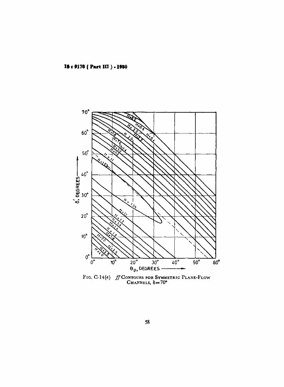
FIG. C-14(e)
10· 20' JO' 40' 50·ep,DEGREES •
ffCONTOURS FOR SYMMETRIC PLANE-FLOW
CHANNELS,1)=70'
58
IS 19178 (Part III ) .1980
..20· 30· 40·8p,DEGREES--------1-
•aO~·--"*"=---::*="-"""""""I-::--......7---±~-~
IIIWWll:C)ILlc
".0 2[jf----'.......:-+-----",
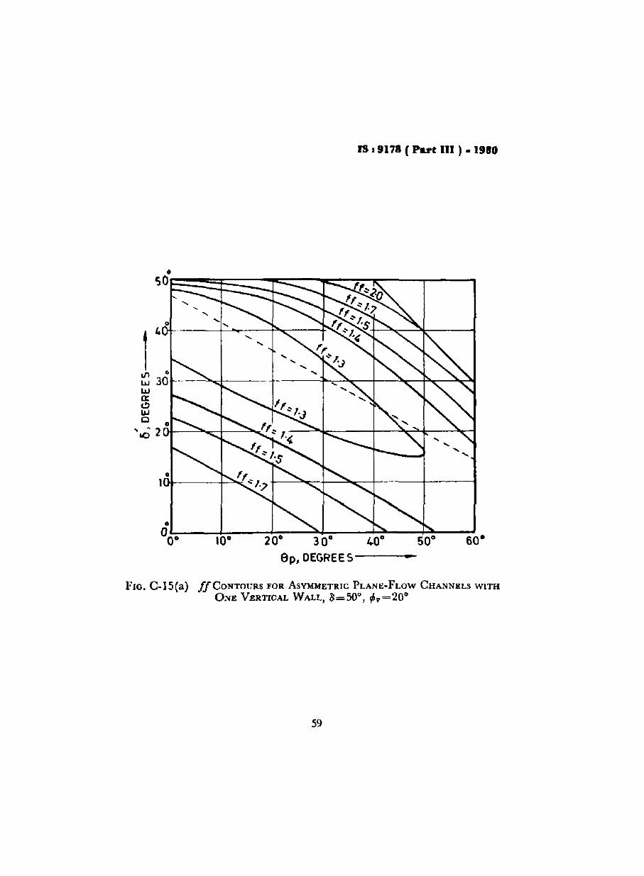
FIG. C-15(a) ffCONTOURS FOR ASYMMETRIC PLANE-FLOW CHANNELS WITHONE VERTICAL WALL, 3=50°, ~v=200
59

IS I 917B (Part m i- 1980
-20° 30°ep , DEGRE ES -------<1_
0° '":-__........~__....... ....L.-__""'-"'-__~'-:-__.......
if ~o
III 30°ll.J <,
ll.J <,
a: -,Cl <,W <;0 20° "-.10
FlO. C-15{b) ffCONTOtJRS FOR ASYMMETRIC PLAN1!-FLOW CHANNELS WITH
ONE VERTICAL W!lLL, 0=50°, l/iy=30°
'" -
50°
40°
30° °
If)
20w U
J cr.
(.!) w a
0
-,-
10co
<,
<,
ff::
'.3".
..
... fIl .. \Cl" ... ~
~
FlO
.C
-15(
c)ff
CO
NT
OV
JlS
FO
RA
SY
MM
ET
RIC
PL~NE·FLOW
CH
AN
NE
LS
WIT
HO
NE
VE~TICAL
WA
LL
,B
=50
°,¢
'l=
40
0
0°0°
10°
20°
30°
40°
ep
,DE
GR
EE
S
50°
60"
:' .. .. ... ... ...~
... la g

IS I 917. (Part III ) • l!IBO
b) Hopper Wall
c) Flow Properties ofBulk Material
d) Estimated HopperSlope Angle Bo
APPENDIX D( Clause 7.8.4 )
RECOMMENDED CALCULATION SHEET FOR DESIGNOF BINS FOR MASS FLOW
0.1. DESIGN WITH CONICAL ( SQ.UARE/CIRCULAR ) OUTLET
a) Bulk Material i) Material:it) Size:iii) Condition:IV) Average Bulk Density w:
i) Material:ii) Fmish:
i) Shear Cell Area, A.:it) Estimated 8 at outlet:iii) Estimated 8' at outlet:
i) Estimated if:(Fi.'(.C-13)
ii) Estimated Be:(FIg A-B, stay 5° within boundary)
V.R(S)A•. w
Select lower jJ for anintersecuon il possible,Selectedj(:
Select a point ( V. p) onif such that V = 1'5 F( V, V):( V, F):Min outlet dimension
P. H (8e )bo = --,---'--=-
A. w
i) H ( 6e ):(FIg. C-12)
ii) Estimated jJ
For no interaction of .lJwith FF:Case I : FF lies below if
( free flowing material) bo =
Case 2: FF lies below if
iia)
JJ ( correction if any):I ntersection if with FF ofstored material ( V, V):
iib) ForJJlying between FF0 and FF t :
e) Estimation of OutletDimensions:
62

v=
Corrected ll' =
Corrected Oc =
IS : 9178 (Part III) • 1988
f) Check
V = Corresponding I) =By drawing Mohr's semicircle through (V, 0 ) and tangential toErL and its intersection with HTL.
S' at outlet =Corrected =
Corrected ff =
H (Oc) =
Minimum outlet dimensions, ho= r' ~U~olA. w
g) Adopted Values for Design
Hopper slope angle Bo =
Outlet dimensions Eo = Circular/Square
D.2. DESIGN WITH PLANE FLOW CHANNEL - Rectangular/fullslot outlet
a) Bulk Material
b) Hopper Wall
c) Flow Properties ofBulk Material
d) Esurnated HopperSlope Angle Op
e) Estimated outletDimensions
Estimated .if
I) Material:
]1) Size:
111) Condition:
IV) Bulk density w:
i) Material:
ii) Finish:
i) Shear cell area, As =
ii) Estimated II at outlet =iii) Estimated S' at outlet =
i) Estimated ff'( FIg. C-14 or Fig. C-lS )
ii) Estimated Op =( Flg. C-B )
i) H ( Bp ) =
ii) Estimated if:
63

IS I 9178 (Part lit) • 1980
Hal For no intersection .ffwith FF.
iib) for.fJ I} ing betweenFFo = and FFt
Case I : FF lies belowjJ ( Free flowing material)
bo
= F. H (0)A•. w
Case 2 : FF lies Select lower .fJabove .fJ for an intersection,
if possible
=.!!ljJ ( Correction, if any):
Lntersection of ifwuh FF of bulkmaterial ( V, V) =
Select a point ( V, V) on ifsuch that V = 1'5 F(V,V)=
(V,F)=
V=H (Op) =
( C orrection if any) -Min outlet dimension bo = V. He 9)
A•. w
=
, Corrected 11'
l Corrected Op -V
I) Check
V = , Corresponding II =
By drawing Mohr's semicircle through ( V, 0 ) and tangential toEYL and its intersection With WrL.
11' a t outlet =
Corrected 11 =
Corrected.ff =
H (Op)
Minimum outlet dimensions,
g) Adopted Values for Design
Hopper slope angle Ill' =Outlet dimensions = ( Circular, Square)( Rectangular 1 :> 3bo, Full slot 10 :> 6 bo )
64

IS: 9178 ( Part Dr) .1980
APPENDIX E( Clause 10.6 )
RECOMMENDED CALCULATION SHEET FOR THE DESIGNOF BINS AND HOPPERS FOR FUNNEL FLOW
=
a) Bulk Material
b) Hopper Wall
e) Flow Properties ofBulk Material
d) Hopper Slope Angle, 6
e) Outlet Dimensions
i) Bulk size:ill Average bulk density:iii) Lump size:iv) Condition:
i) Material:ii) Fmish:
i) Shear Cell area, A.ill Average S =
iii) Average,'" =
i) Flow factor, if =( see Fig. C-9 of Appendix C )
ii) 6. or Bp =( see Frg. c-io of Appendix C )
i) .ff=
ill Intersection of.ffwith flow functionof bulk material( V, V) =
iii) V =-
iv) G (1)) ( see Fig. e-n ofAppendix C )
v) H (8) ( see Fig. 12 ofAppendix C)Major dimension of outlet, do
d I V.G(r/»o or 0 = A•. w
Minor dimension of outlet,
bo = V JL£~As. w
Square outlet side, bo = 101v' :!
Circular outlet Diameter, do =
Rectangular outlet Smaller side,bo = , Bigger side 10 =
65
18 I 9178 ( Part UI ) • 1980
Adopted outlet dimensions -( Circular/square/rectangular)(Minor dimensions >0 6 X maximum lump size)Adopted slope of hopper =(9c or 9p )
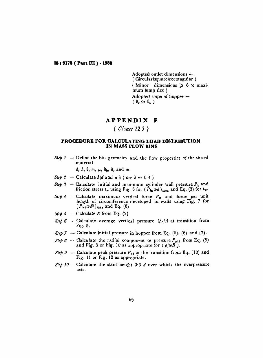
APPENDIX F( Clause 12.J }
PROCEDURE FOR CALCULATING LOAD DISTRIBUTIONIN MASS FLOW BINS
Step 1 - Define the bin geometry and the flow properties of the storedmaterial
d, h, 8, m, ~, lib, 8, and ~.
Slep 2 - Calculate" fd and ~ ,\ ( Use ,\ £: Q. 4 )
Step:1 - Calculate initial and maximum cylinder wall pressure Pb andfriction stress I." using Fig. 6 for ( Ph/rod )mall and Eq. (3) for t.".
SlfP 4- - Calculate maximum vertical force P." and force per unitlength of circumference developed in walls using Fig. 7 for( P."Jrods)mu and Eq. (8)
Slip 5 - Calculate R from Eq. (2)
Step 6 - Calculate average vertical pressure Qc/A at transition fromFig. 5.
Step 7 - Calculate initial pressure in hopper from Eq. (5), (6) and (7).
Step 8 - Calculate the radial component of prrssure Pntr from Eq. (9)and Fig. 9 or Fig. 10 as appropriate for (a/roB).
Step 9 - Calculate peak pressure Pn\ at the transition from Eq. (10) andFig. 11 or Fig. 12 as appropriate.
Step 10 - Calculate the slant height 0'3 d over which the overpressureacts.
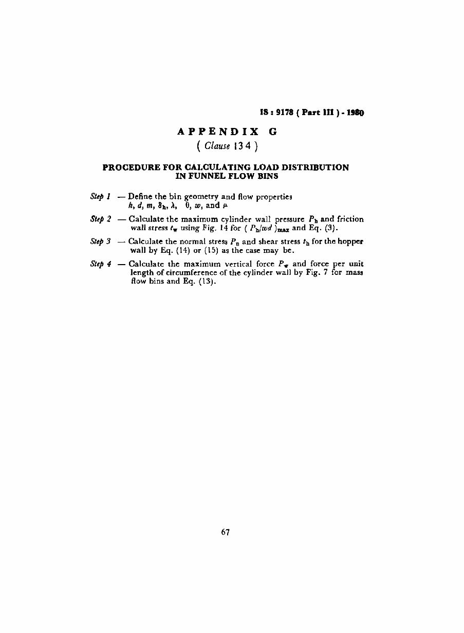
IS I 9178 ( Part m ). 1980
APPENDIX G( Clause 13 4 )
PROCEDURE FOR CALCULATING LOAD DlSTRmUTlONIN FUNNEL FLOW BINS
Sltp 1 - Define the bin geometry and flow propertiesh, d, m, 8h, ~, Il, W, and ~
Sttp 2 - Calculate the maximum cylinder wall pressure Ph and frictionwall stress t." using Fig. 14 for ( Pb/wd)mu and Eq. (3).
Sttp 3 - Calculate the normal stress Po and shear stress tb for the hopperwall by Eq, (14) or (15) as the case may be.
Sttp 4 - Calculate the maximum vertical force P." and force per unitlength of circumference of the cylinder wall by Fig. 7 for massflow bins and Eq. (13).
67

INDIAlil STANDARDS
ON
STRUCTURAL ENGINEERING
Struc/llral S,./lon
IS:
808-1964 Railed steel beam channel and angle sections (,erns,d)
808 (Pa,t I )-1973 Dimensrons for hot-rolled steel Iloaml: Part I MB series (second"011;01/ )
811-1965 Cold formed light gauge structural steel sections ( rev;"d)
1252-1958 Rolled steel sectrons bulb angles
1730 (Part I )-1974 Dirnensrons for steel plate, sheet and strip for structural andgeneral engmeenng purposes: Part I Plate (fi's/ "v....n )
1730 ( Part II )-1974 Dimensions for st eel plate. sheet and strip for structural andgeneral engrneermg purposcs: Part II Sheet (first "onIOn)
1730 ( Part III )-1974 Drmcnsrons for steel plate, sheet and strip for structural andgeneral cngmeerrng purposes: Part III Strip (first reo",.n )
1852-1973 Rolling and cuttmg tolerancrs for hot-rolled steel products (s<COl1d reV'SI.n )
2713-l969 Tubular steel poles for overhead power lints (ji"l reolHon)
3908-1966 Aluminium equal leg angles
3909-1966 Alumunurn unequal leg angle.
3921-1966 Aluminium channcls
395-1--1966 Hot rolled steel channel sectrons for general engineering purposes5384-1969 Alumimum I beam
6445-1971 Aluminium tee sect ions
Coder of Praetue
800-1962 Use of structural steel in general buildmg construction (reois,d)
801-\975 Use of cold formed light gauge steel structural members 10 general buildmgconstruction
802 ( Part I )-1977 U,e of structural steel in overhead transmission hne towers:Parr I Load, and perrmssible stresses ( second revisIOn)
803·1976 Dcsrgn, Fabrrcation and erection of vert ica l mild steel cylindrical weldedall storage tanks (first reolSlOo )
805·1968 Use of steel in gravity water tanks806·1968 Use of steel tubes in general burlding construction (reo<Jed)807.1976 Design. manufacture, erectron and testing (structur.l portion) of cranes
and hoists (first ,eoUlon )3177-1977 Electrrc overhead travellIng cranes and gantry cranes other than steelwork,
cranes (fifjt revISIon)
4{}OO·1967 Assembly cf strucrura! jornrs USing !Ilgh tensile fClctwn gelp fasteners
4014 ( Part I )-1967 Steel tubular acatfcldings: Part I Defimtrons and materrals4014 ( Part II )-1967 Steel tubular scaffoldings. Part II Safety regulations for
scaffoldmg

IS:
4137-1967 Heavy duty electric overhead travelling cranes including special servicemachines for use in steel works
6533-1971 Design and construction of steel chimney.7205-1973 Safety code for er ectron of structural steelwork8147-1976 Code of practrce for use or alumimurn alloys in structures8640-1977 Recommendations for dimensronal parameter' for industrial huildings
G.n.,al
81H-1957 Rectangular pressed steel tanks (firs' remsion )
72[5-1974 Tolerance. for fabrication of steel structure.808[·1976 Slotted sections
HandlJo.lcs for Structural Engln."s
No. I Structural steel sectronsNo.2 Steel heams and plate girdersNo.3 Steel column and SlrutsNo." High tensile friction grip boltsNo.5 Structural use of hght gauge steelNo.6 Application of plastic theory in design of steel structure,No.7 Simple welded glrders

INTERNATIONAL SYSTEM OF UNITS (SI UNITS)
B••• Unltl
Quantity
LengthMallTime
Electric current
Thermodynamic
tern peratu re
LumInous Intensity
Amount of substance
Unt! Symbol
melre mkilogram kgsecond s
ampere A
kelvin K
candela cdmole mole
Supplementary Unite
Quantity
PIUe angle
Solid angle
Derived Unit.
Quantity
ForceEnergy
Power
Flux
Flux denslly
Frequency
Electric conductance
Eleclromollve [orce
Pressure, streSS
Unit
radian
slerad Ian
Utut
newton
louie
wallweber
tesla
hertzsiemens
volt
pascal
Symbol
rad
sr
Symbol
NJW
Wb
T
Hz5VPa
Definition
1 N = 1 ~g.m/Sl
1 J - 1 N.m1 W = 1 J{s
I Wb = I V s1 T = 1 Wb/m!1 Hz = 1 cis (S_I)
1 S = 1 A{V1 V = 1 WIA
1 Pa = 1 N/mt