IS 771-1 (1979): Glazed Fire-Clay Sanitary Appliances ... · IS t 771 ( Part I ).1979 Indian...
21
Disclosure to Promote the Right To Information Whereas the Parliament of India has set out to provide a practical regime of right to information for citizens to secure access to information under the control of public authorities, in order to promote transparency and accountability in the working of every public authority, and whereas the attached publication of the Bureau of Indian Standards is of particular interest to the public, particularly disadvantaged communities and those engaged in the pursuit of education and knowledge, the attached public safety standard is made available to promote the timely dissemination of this information in an accurate manner to the public. इंटरनेट मानक “!ान $ एक न’ भारत का +नम-ण” Satyanarayan Gangaram Pitroda “Invent a New India Using Knowledge” “प0रा1 को छोड न’ 5 तरफ” Jawaharlal Nehru “Step Out From the Old to the New” “जान1 का अ+धकार, जी1 का अ+धकार” Mazdoor Kisan Shakti Sangathan “The Right to Information, The Right to Live” “!ान एक ऐसा खजाना > जो कभी च0राया नहB जा सकता ह ै” Bhartṛhari—Nītiśatakam “Knowledge is such a treasure which cannot be stolen” IS 771-1 (1979): Glazed Fire-Clay Sanitary Appliances: Part-1 General Requirements [CED 3: Sanitary Appliances and Water Fittings]
Transcript of IS 771-1 (1979): Glazed Fire-Clay Sanitary Appliances ... · IS t 771 ( Part I ).1979 Indian...

Disclosure to Promote the Right To Information
Whereas the Parliament of India has set out to provide a practical regime of right to information for citizens to secure access to information under the control of public authorities, in order to promote transparency and accountability in the working of every public authority, and whereas the attached publication of the Bureau of Indian Standards is of particular interest to the public, particularly disadvantaged communities and those engaged in the pursuit of education and knowledge, the attached public safety standard is made available to promote the timely dissemination of this information in an accurate manner to the public.
इंटरनेट मानक
“!ान $ एक न' भारत का +नम-ण”Satyanarayan Gangaram Pitroda
“Invent a New India Using Knowledge”
“प0रा1 को छोड न' 5 तरफ”Jawaharlal Nehru
“Step Out From the Old to the New”
“जान1 का अ+धकार, जी1 का अ+धकार”Mazdoor Kisan Shakti Sangathan
“The Right to Information, The Right to Live”
“!ान एक ऐसा खजाना > जो कभी च0राया नहB जा सकता है”Bhartṛhari—Nītiśatakam
“Knowledge is such a treasure which cannot be stolen”
“Invent a New India Using Knowledge”
है”ह”ह
IS 771-1 (1979): Glazed Fire-Clay Sanitary Appliances:Part-1 General Requirements [CED 3: Sanitary Appliances andWater Fittings]

IS: 771 ( Part I ) - 1979
Indian StandardSPECIFICATION FOR
(REAFFIRMED 2007)
GLAZED FIRE-CLAY SANITARY APPLIANCESPART I GENERAL REQUIREMENTS
( Second Revision)
Third Reprint JULY 1998( Incorporating Arueudmeut No.1 )
UDC 696.14:666.647
Copyright 1984
BUREAU OF INDIAN STANDARDSMANAK BHAVAN, 9 BAHADUR SHAH ZAFAR MARG
NEW DELHI 110002
Gr 4 September 1979
IS : 171 ( Part I ) • J979( R~ammu~d 1997 )
Indian StandardSPECIFICATION FOR
GLAZED FIRE-CLAY SANITARY APPLIANCESPART I GENERAL REQUIREMENTS
( Second Revision)Sauita ry Appliances and Water Fittings Sectional Committee, Bne 3
CI,,,irman
SURI V. D. DKSAJ
Representing
Bombay Municipal Corporal ion
Members
Central Public Health & Environmental EngineeringOrgamzarion ( Ministry of Works & Housing)
AnVISt<:R
SURT B. B. R."l" ( Alternate)SUUJ H. R. B \I)Y .\L Indian Iron & Steel Co Ltd, Calcutta
SUIt,r K. D. BIS\YAS ( Alurnat« )SUIU M. K. B.A8U Central Glass & Ceramic Research Institute
( CSIR ), AhmadabadDirectorate General of Technical Dtv~lopmentt
New DelhiSnnr T. RAMA8t1BRAMANIAN ( Alt,rndl. )
SHRI S. P, CHAKRABABTI Central Building Research Institute (CSIR),Roorkee
SUIU S. K. SHARMA ( Alternate)CUJI!:F ENOINJ·~p.:n Public Health Engineering Department, Government
of Kerala, Tt ivandrurnSllRI K. RAMACHANDR.O\¥ ( Alternate)
CHI.)' ENOINEJo;R Tamil Nadu Water Supply & Drainage Board.Madras '
CUIEr ENOINBER U. P. Jal Nigam, LucknowSUPERINTENDING ENQINF:~R ( Alternate)
CUIEr ENOlNEER ( WATER ) Municipal Corporation of D~lhi, Dt'"lhiDRAINAGE ENOIN1t:EB ( Alternat» ) ,. .
88ftl L. M. CHOUDHARY Public Health Engineering Department, Governmentof Haryana, Chandigarb
SURI D. S. CUABJrAL
Su ut I. CUANllUA ( AII"nat, )
( Conti,,",d on I'd" 2 )
C> C.fJ)ri,ht 1984BUREAU OF INDIAN srrANDARDS
Thi. publicatioD it protected under the lNJidfl Co/J.1ri,hl Ad ( XIV of 1957 ) andreproduction in whole ot in part by any mean. except with written permission of thepublisher .hall be deemed to be aD inlrinlemcDt of copyright under the said Act.
IS I 771 ( Part I ) • 1979
( C.,,'inu,tJ from pal' I )
M,mb", It,pr",ftli",CITY EMQIMBJ4~l\ Bombay Munitipal Corporation
HYDRAULIC ENGINEER ( AI",,,.,, )SIIKI H. N. DALLA. Indian Institute of Architects, BombayLALA G. C. DAs National Test House, CalcuttaSUU,I T. R. IJE Institution or Engine~rl ( India ), CalcuttaDIRECTOR Bombay Potteries & Trles Ltd, Bombay
SHRI A. M. KEMBRAVI ( AI,.,,,.,, )SaRI B. R. N. GUI'TA Englneer-in-Chief''s Branch ( Army Headquarters )
SHRI K. V. KRISHNAMURTHY ( AII,mal, )SJJRJ M. "f. KAHlE Director ate General of Supplies & Disposals,
New DelhiSUIU S. R. KIIUIlSAOAIl National Environmental Engineering Researcb
Institute ( CSIR ), NagpurSHRI R. C. REDDY ( Alt"lUIt, )
SHIn K. LAXSBMINARAYANAN Hindusran Shipy.ard Ltd, VishakhapatnamSHill A. SHARI"" ( Alt,r"t.ll, ) •
SsaJ P, S. RAJVANSBJ Public Health Engineering Department, Governmentof Rajasthan, Jaipur
SaRI R.NJIT SINGH Railway Hoard ( Ministry of Railwavs )Da A. V. R. RAO National Buildings Organiaation, New DelhiSUBI P. JAOANATH RAO E. I. D.-Parry Ltd, Madras
SHRt M. MOOSA SULAIMAN ( AlI"ntJl, )SaRI R. K. SOMANY Hindustan Sanitaryware & Industries Ltd,
BahadurgarhSUPERINTENDING SURVEYOR or Central Public Work. Department, New Delhi
WORKS (NDZ)SURVEYOR 0' VVORKS
( NDZ ) ( Alt"tlat, )SHIt! D. AJITIIA StMRA, Director General, [51 ( Ex-officio M...." )
Director ( Civ Enll )
S"'''tJ,-,SaRI S. P. MAOOU
Assislant Director ( Civ Engg ), lSI
Domestic Sanitary Appliances and Accessories Subcommittee,DDC 3: 1
Co,."".,,
SUKI G. F. KHAMn~TTJ Bornhay Municipal CorporatioD
Indian Plastic. Ltd, Bombay
Ministry of Railway.
Central Glass It ~ramic Ranreb Inltitute( aSIR >, Ahmadabad .
SUR. G. T. BRIDK National Buildiap OrganizatioD, New Delhi:SURI O. P. RATltA ( AI,,,,..,, )
M,mb",Saar M. C. AOItAWAL
SaRI N. L. BUlLA ( Al',tn.', )A.I.STANT DJln~c:rOR. STAlfD
ARDS (A ReB 1 T It C T U R P; )
(ROSa)SlIRI M. K. BASU
( c.lI'i"",d fa /M" 16 )
2
IS t 771 ( Part I ). 1979
Indian StandardSPECIFICATION FOR
GLAZED FIRE·C'LAY SANITARY APPLIANCESPART I GENERAL REQUIREMENTS
(Second Revision)
o. FOR E W 0 R D
0.1 This Indian Standard ( Part I ) (Second Revision) was adopted by theIndian Standards Institution on 4 May 1979, after the draft finalized bythe Sanitary Appliances and Water Fittings Sectional Committee hadbeen approved by the Civil Engineering Division Council.
0.2 This standard was first issued in 1958 and was revised in 1963 tocover requirements for additional glazed earthenware sanitary appliances,such as orissa pan, laboratory sink, squatting plate, slab and stall urinaland half-round channel. In this revision the scope of the standard hasbeen restricted to cover requirements for glazed fire-clay sanitaryappliances only since the glazed earthenware sanitary appliances wereoutdated as well as unhygenic. The Sectional Committee has found thatonly some of the sanitary appliances were being made in glazed fire-clayand therefore decided to cover the requirements for these appliances onlyin this revision. The general requirements applicable to all appliancesand specific requirements for different appliances have been covered inseparate parts of the standard. This standard ( Part I ) deals with thegeneral requirements of all glazed fire-clay sanitary appliances.
0.3 For the purpose of deciding whether a particular requirement of thisstandar4 is complied with, the final value, observed or calculated, expressing the result of a telt or analysis, shall be rounded off in accordancewith IS : 2·1960·. The number of significant places retained in therounded off value ahopld be the same u that of the specified value in
.this standard.
1. SCOPE1.1 This standard (Part I) coven t~e general requirements for materials,manufacture, finish, methods of test. sampling and inspection of allilazed.&re-clay aanitary appliances.
eRula ror rouadilll off Dum~lcalnlua ( FIR_ ).
9
IS : 771 ( Part I ) · 1979
1.2 This standard does not cover vitreous sanitary appliances. Requirements of vitreous sanitary appliances have been covered in IS: 2556( Part I )-1974*.
2. TERMINOLOGY
2.0 For the purpose of this standard, the following definitions shallapply.
2.1 BI18ter - A raised portion of the surface protruding not more th.mone millimetre above the surface and not greater than 3 mm in itsmaximum dimensions,
2.2 Bubble - A raised portion of the surface or a sand speck not morethan one millimetre in its maximum dimensions.
2.3 Cra•• or Craallll - Fine hair-line cracks in the glaze.
2.t 0.11 or BII Shell fl_1I - Dead or flat finish with undevelopedglaz~ slightly matted in appearance or a semi-glazed finish exhibitingnumerous very fine pinholes and non-glossy appearance.
2.5 Daat - A hair-line fracture extending through or into the body ofthe article.
2.6 Bspoaecl ."y- Unglazed portion 1·5 mm or more in its maximumdimension.
2.7 I'lreclaeck or Plre-Cnck - A fine, shallow crack in the body, notcovered with glaze.
2.1 KAI. Sappon Ma..b - Large unglazed surfaces resultiDg fromblocks necessary to support the ware while firing.
2.' .laIaole - UDglazed portion or a hole in the body leu than l'S mmin itl maximum dimeDiion.
2.10 PoUI"a. Mar. - A I~t where some minor blemish hal beenground off and lurface polished, the area of the spot not exceeding thearea of a 10 mm diameter circle.
2.11 Pette.., ....... - A aquare of dimensions 50 X 50 mm selectedon the appliances for examining visual defects.
2.12 &peek - An area of cODtrutUtS colour less than one millimetremaximum dim_oDl. Specb Jeu than &25 mm, maximum dimension,do not constitute a defect ualaa auftiCiCDt iD Dumber to form a discolouration.
·SpecilcadoD lew ..... IUIlIUJ appllaDca ( "'NOIII cbIDa): Pan I 0--..requireID.II ( ....,.".).
IS I 771 ( Part I ) • 1919
2.13 Spot - A discoloured portion of the surface not exceeding 3 rom inits maximum dimension.
2.14 Warpale - Distortion of original shape during the manufacturingprocess.
2.15 Wavy FIDI.b - A defect in the glaze finish having the appearanceof numerous runs in the glaze, irregular or mettled,
3. MATERIAL, MANUFACTURE AND FINISH
3.1 Materi.l .Dd Maaafactare- Fire-clay bodies arc moderately fine,porous, off-white bodies using natural fire clays, ball clays or stonewareclays and clay grogs covered by a glaze properly matured and fitted tothe body.
3.2 PerlDl••lble Bleml.he. aDd Defect.
3.2.1 When examined from any point within the viewing circle describedbelow, the appliances shall not show to the unaided eye of a trainedobserver blemishes or defects in excess of those listed in Table 1.
3.2.1.1 The viewing circle referred to is 1 200 mm in diameter andlies on a plane parallel with and 600 mm above the rim of the appliances.A line joining the centre of the circle and the centre of area of the insideboundary of the rim is perpendicular to the plane of the viewing circle.
4. MINIMUM THICKNESS
4.1 The thickness at any place in an appliance shall not be lessthan 8 mm,
5. GLAZING
5.1 All visible lurfaces of the body shall be glazed. Surfaces coming incontact with 8001° or wall and the underside of sinks, etc. and pointswhere appliances are supported in the kiln may be unglazed.
5.2 The glaze shall be uniform, free from craze and shall possess animpervious surface. It shall have a high glols and shall normally be whitebut may be supplied in any other colour as agreed to between themanufacturer and the purchaser. In the case of glazes containing lead,the lead content shall not exceed 5 percent of soluble lead when testedby the method described under 5.2.1.
5.2.1 A quantity of material ( glaze) or known mas. dried at 100·0~11 be Iq.~en continuously for one hour (at room temperature)wit)) 1 000 tiAles itl ma. of dilute hydrochloric acid. Thereafter. it mallbe -allowed to Itand for one hour and then filtered. The lead saltcontained in the clear filtrate ahall be precipitated al lead sulphate.
5
IS : 771 ( Part I ) • 1979
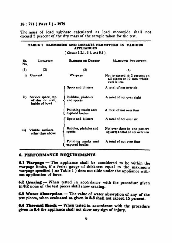
The mass of lead sulphate calculated as lead monoxide shall notexceed 5 percent of the dry mass of the sample taken for the test.
TABLB I BLBMlIHES AND DEFECTS .BRMIn-ED IN VARIOUSAPPLIANCES
( ClalU'.. 3.2.1, 6.1 J and 8.1 )
SL LOOATION BLEMISH OR DEI'BCT M.6XIIItTII PERMITTEDNo.
(I) (2) (3) (4)
i) General W.rpage Not to exceed :I: 2 percent onall planes or 10 mm which-ever is leu
rSpot. and bli.ter. A total of not over six
ii) Scrvice Ipace, top i Bubbles, pinholes A total ofoot over cilhtor rim or alab, and specksinside 01 bowl
l Polishing marks and A total of not over fourexpoaed bodies
Spot. aDd blister. A lota1 or not over lix
iii) Viaible IUrf.cesother thaD above
Bubblel, piDhola aDd Not over three in one potterylpeCka lqU&reja total of not over ten
Polbbins markl andexpesed bodies
A total of Dot over four
6. PERFORMANCE REQ,UIREMENTS
6.1 Warpale - The appliance shall be considered to be within thewarpage limits, if a feeler gauge of thickness equal to the maximumwarpage specified ( I" Table 1 ) doe. not slide under the appliance with.out application of force.
1.2 Cn_. - When tested in accordance with the procedure givenin 8.2 none of the telt pieces I~ show crazing.
U Wate.. AIa.....tl•• - The value of water absorption or any of thet~ pieces, when evaluated as given in U Ihall Dot exceed 15 percent•
... TIaenaaI I••• .....;. When tested in accordance with the proceduregiven iDI.t the appljaace thall Dot mow aUf Ijp or injury.
6
IS : 771 ( Part I ) • 1979
6.5 Claemical ...I.taace - When tested by the method described inAppendix At none of the test pieces shall appear to the unaided eye of atrained observer to have suffered any loss of reflectivity of the glaze whencompared with the control sample.
6.6 M_.I.. or Rapt1lre - The average modulus of rupture of tensamples when tested by the method described in 8.6 shall not be lessthan 20 MPa.
&.6.1 Values taken for determination of the mean value shall not varymore than ± 20 percent of the mean value. Values above or below20 percent of the mean may be discarded for the calculation of the meanvalue. If the fractured surface of test pieces show lamination crack or acavity at the centre or any other defect, those test pieces shall berejected.
6.7 R ••I.taace to StalnlDS aDd BarulDg- When tested by the methoddescribed in Appendix B no stain shall remain on either of the testpieces.
7. PROCESS INSPECTION AND LOT INSPECTION
7.1 The recommended methods for process inspection and lot inspectionare given in Appendix C.
8. TEST PROCEDURES
8.1 Warp_Ie - The appliance shall be placed face down on a flatsurface preferably a surface plate to ascertain the amount of deviationfrom the horizontal that exists at the edges of the appliance. If the
.appliance rocks on two points, a horizontal plane shall be-determined byplacing the feeler gauge of a thickness equal to the maximum warpagepermitted for the appliance (s" Table I ) under one low corner andforcing the appliance down on this gauge. If a second feeler gauge ofthe same thickness does not slide at any other point. the appliance shallbe considered as not warped out of the horizontal plane and to be inconformity with the permissible w.rpage limits.
1.2 0 ....' •• - Three test pieces each having an area of not lessthan 100 em' on one aide shall be broken from widely separated parts ofthe article. At least one major surface shall be glazed surface. Careshall be takc;n not to produce cracks either in the body or in glaze; anysuch pieces shall be discarded. Surfaces other than major lurfaces shallbe unglazed and freshly broken. Alternatively. sample pieces having thelame surface area .a mentioned above may be aeparately prepared, uaingthe same body 'and glaze materials used in making the appliances of thebatch and put throulh the kiln aloDS with the appliances.
7
IS I 771 ( Part I ) · 1979
8.2.1 Test Procedures - The sample pieces shall be placed" in anautoclave and subjected to a constant pressure of 0-35 MPa in saturatedsteam for 5 hours. The test pieces shall then be allowed to cool to room"temperature inside the autoclave. They shall then be examined forcrazing by applying a dye solution to the surface.
8.3 Water AbsorptioD Teat
8.3.1 The test samples shall consist of three fragments taken fromwidely separated parts of the appliance, each fragment having at leastone of the two major surfaces fuHy glazed and having a surface area ofapproximately 75 crn l • Surfaces other than major surfaces shall beunglazed and freshly broken, care shall be taken not to produce crackseither in the body or in the glaze, any such pieces shall be discarded.Alternatively, test pieces of the same surfacearea and 10 rom minimumthickness with one major surface glazed shall be separately made usingthe same batch and glaze material as used in making of the appliancesof the batch and put through the kiln along with the appliances.
8.3.2 Test Pracedur« - The test piece shall be dried to a constant massat 110 ± 5°C and shalJ then be stored in a desiccator until cooled toroom temperature. The specimen shall then be weighed in a balance toan accuracy of 0-5 g. The weighed pieces shall then be placed indistilled water in a suitable vessel and boiled for two hours. They shallbe supported so as not to touch the heated bottom of the container. Thepieces shall then be allowed to cool and remain in water overnight. Thetest pieces shall be wiped dry with a damp cloth in such a manner as toremove the surface water only and then weighed.
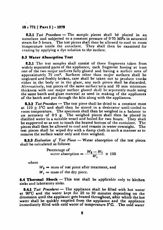
8.3.3 Evaluation of Test Pieces - Water absorption of the test piecesshall be calculated as follows:
Percentage of _ J.t': - WIwater absorption == --LW~ X 100
whereW2 =- mass of test piece after treatment, andWI = mass of the dry piece.
8.4 Thermal Sbock - This test shall be applicable only to kitchensinks and laboratory sinks.
8.4.1 Test Procedur,s - The appliance shall be filled with hot waterat 90°0 and the water kept for 20 to 30 minutes depending on thedimension until the appliance gets heated throughout, after which the hotwater shall be quickly emptied from the appliance and the applianceImmediately filled with cold water of temperature SoC. .The cold water
8
IS I 771 ( Part I ) • 1979
shall be kept in the appliance for 20 to 30 minutes until the appliancegets thoroughly cooled, after which the cold water shall be quicklyemptied trom the appliance and the cycle repeated. After the repetitionof the cycle for 5 times, the appliance shall not show any sign of injury.
8.5 Tests for Chemical Resistance - The test procedure for chemicalresistance is given in Appendix A.
8.6 Modulus of Rupture8.6.1 T'est Pieces - Sample test bars shall be separately prepared, using
the same body materials as used in making the appliances of a batch andshall be fired in the same kiln along with the appliances. They shall besq uare or circular in section and the cross-sectional area shall not be lessthan 150 mm' and 150 rom long and shall not be glazed.
8.6.2 Test Procedures - The modulus of rupture shall be determined byusing at least 10 of these bars mounted on supports 125 mm apart, andloaded rapidly ( approximately 50 N per second) at the mid point.
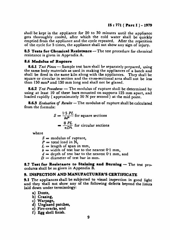
8.6.3 Evaluation of Results - The modulus of rupture shall be calculatedfrom the formula:
1·5 PL .S ::::I:~ for square sections
8 PL,. · 1 ·- ~ lor circu ar secnons
whereS z= modulus of rupture,P = total load in N,L == length of span in mrn,b =- width of test bar to the nearest 0·1 rom.d aD depth of test bar to the nearest 0·1 mm, and
D = diameter of test bar in rnrn,
8.7 Te.t for Re.lstaDce to StalDmc aad Barnlag - The test procedures shall be as given in Appendix B.
9. INSPECTION AND MANUPACTURER'S CERTIfiCATE9.1 The appliances shall be subjected to vis.ual inspection in good lightand they shall not show any of the following defects beyond the limitslaid down under terminology:
a) Dunts,b) Crazing,c) Warpage,d) Unglazed patches,c) Fire-cracks, andf) Egg shell finish.
9
IS I 771 ( Part I ) • 1979
9.2 Where agreed to between the purchaser and the vendor, the purchaseror his representative shall be given all facilities for inspection of the goodsat all stages of manufacture and finally prior to despatch from the manufacturer's works.
9.' When no inspection of the goods is made by the purchaser or hisrepresentative at the manufacturer's works, the manufacturer, if requestedto do so, shall supply a certificate stating that the goods suppliedconform in all respects to this standard. The manufacturers certificatewill not be necessary if the article bears the lSI Certification Mark.
I." The purchaser shall be at liberty to reject any goods purporting tohave been supplied to this standard, if they do not comply with therequirements of this standard. ;
10. MARKING
10.1 Appliances shall be clearly and indelibly marked at a prominentplace, visible even after the appliances are installed, with the name ortrade-mark of the manufacturer.
10.1.1 The fire clay sanitary appliances conforming to the specificrequirements as prescribed in the relevant parts of thia standard may alsobe marked with the lSI Certification Mark.
Non - Tbe UIC of the lSI Certificatioa Mark is loycmed by tbe provisionl ofthe IudiaD Standards Institutioa (Certification Marks) Act and the Rules andReaulatioDi made thereunder, The ISI Mark OD products covered by an IndianStaDdard coove,. tbe ..arance that they have been produced to comply with therequiremeDti or that ItaDdard under a weU-defiDed IYltem or inlpection. tellinl and..lity control which is deviled and lupervised by lSI and operated by theProducer. lSI marked products are also continuously checked by lSI ror conformity10 tbat.t&odard u. rurther .feguard. Detail. or conditions under which a licenceror tbe UI8 eI the lSI Certification Mark may be granted 10 IDanuracturen orproceIIOn, ...., be obtaiaed frOID the IDdiaD StaDd.rda IoatitutioD.
APPENDIX A( Claus,s 6.5 tmd8.5 )
TEST POR CHEMICAL RESISTANCE
A-I. CONTROL TEST PIECE SIZE
.1.1 The teat sample Iball consist of 8 pieces each not smallerthaD 75 X 2~ X 8 mm taken from the glazed part of the appliance. One
\piece placed in a deaiccator and is used as a controlled tel' piece.
10
18 I 711 ( Part I ) • 1979
A-2. PROCEDURE
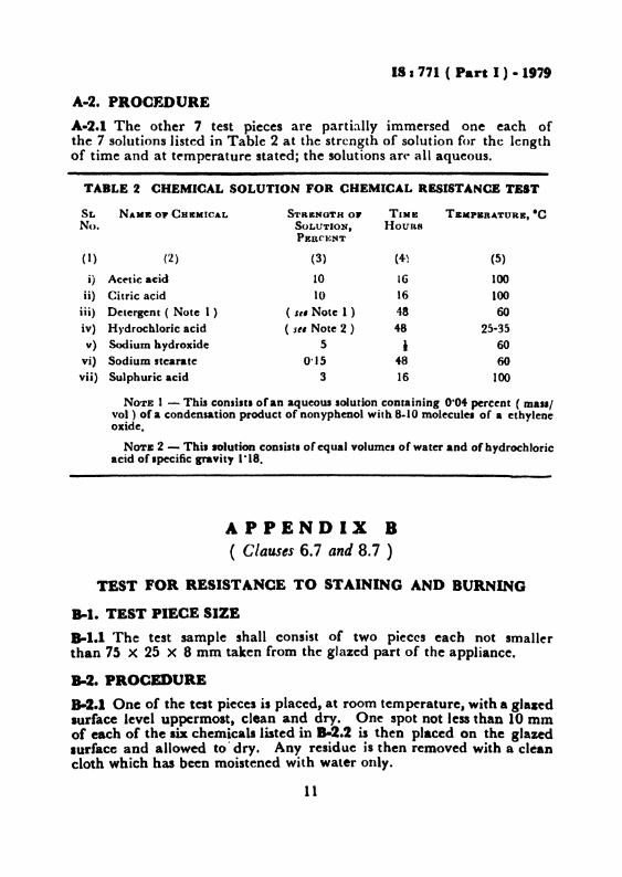
A,-2.1 The other 7 test pieces are partially immersed one each ofthe 7 solutions listed in Table 2 at the strength of solution for the lengthof time and at temperature stated; the solutions art" all aqueous.
TABLE 2 CHEMICAL SOLUTION FOR CHEMICAL RESISTANCE TEST
SL NAME 01" CHEMICAL STRENGTH OJ' TIME TSMPERATURE, ·CNo. SOLUTION, Hotms
PERC~NT
(1) (2) (3) (41 (5)
i) Acetic acid 10 16 100ii) Citric acid 10 16 100
iii) Detergent ( Note 1 ) ( St' Note 1 ) 48 60
iv) H vdrochloric acid ( se« Note 2 ) 48 25-35v) Sodium hydroxide 5 I 60
vi) Sodium stearate 0'15 48 60vii) Sulphuric acid 3 16 100
NOTE I - This consistl of an aqueous solution containing 0·04 percent ( mall'vol) of a condensation product of nonypbenol with 8.10 molecule. of • ethyleneoxide.
NOTE 2 - This solution consists of equal volumes of water and of hydrochloricacid of specific gravity 1·18.
APPENDIX B( Clauses 6.7 and 8.7 )
TEST FOR RESISTANCE TO STAINING AND BURNING
8-1. TEST PIECE SIZE
8-1.1 The test sample shall consist of two pieces each not smallerthan 75 X 25 X 8 mm taken from the glazed part of the appliance.
B-2. PROCEDURE
8-2.1 One of the test pieces is placed, at room temperature, with a glazedsurface level uppermost. clean and dry. One spot not less than 10 mmof each of the aix chemicals listed in 8-2.2 is then placed on the glazedlurface and allowed to' dry. Any residue is then removed with a cleancloth which has been moistened with water only.
11
Each individual applianceTwo piece. of each type of pattern
from a day's production in caseof a continuous kiln and fromeach firing in case of an inter-mittent kiln
IS I 771 ( Part I ) - 1979
8-2.2 The chemicals are the following:
a) 0·5 percent solution of methylene blue,b) 10 percent aqueous solutions of sodium hypochlorite,c) 3 percent aqueous solutions of hydrogen peroxide,d) Amyl acetate,e) Carbon tetrachloride, andf) 13 g of iodine in one litre of ethyl alcohol.
B-2.3 The other piece is placed at room temperature with a glazed surfacelevel uppermost; clean and dry. Lighted cigarette is placed on the glazedsurface and allowed to remain for 15 minutes and then removed. Thestained area is wiped with a cloth which has been moistened withdistilled water only.
APPENDIX C(,CLau.Jt 7.1 )
PROCESS INSPECTION AND LOT INSPECTION
c-r. PROCESS INSPECTION
C-l.l The inspection done by the manufacturer during production is toensure uniformity and reduce quality fluctuations to the minimum wher~.
as the object of inspecting sanitary appliances by the purchaser is toensure itl uniformity to the specification requirements, For process
. control the manufacturer shall take the representative samples of theproduct at regular intervals to control the quality fluctuations, Foritems or the same type, inspection levels given below are recommendedfor routine control over the manufacturing process:
CIw.'eruliel/T'sIs Fr'fJ"''''' of Insp,elio,,/T'sllVilual examination (permissible Each individual appliance
blemishes and defects)WarpageMiDimum thickne..
12
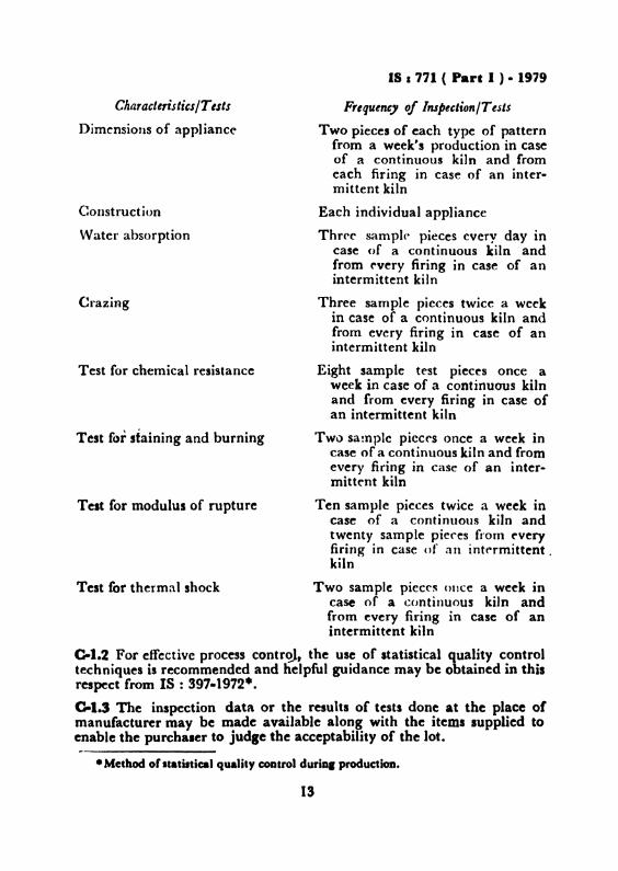
Characle,isticsITests
Dimensions of appliance
Construction
Water absorption
Crazing
Test for chemical resistance
Test for staining and burning
Test for modulus of rupture
IS I 771 ( Part I ) • 1979
Frequency of InspectionITests
Two pieces of each type of patternfrom a week's production in caseof a continuous kiln and fromeach firing in case of an intermittent kiln
Each individual appliance
Three sample pieces every day incase of a continuous kiln andfrom every firing in case of anintermittent kiln
Three sarnple pieces twice a weekin case of a continuous kiln andfrom every firing in case of anintermittent kiln
Eight sample test pieces once aweek in case of a continuous kilnand from every firing in case ofan intermittent kiln
Two sample pieces once a week incase of a continuous kiln and fromevery firing in case of an intermittent kiln
Ten sample pieces twice a week incase of a continuous kiln andtwenty sample pieces from ("veryfiring in case of an intermittent ,kiln
Test for thermal shock Two sample pieces once a week incase of a continuous kiln andfrom every firing in case of anintermittent kiln
0.1.2 For effective process control, the use of statistical quality controltechniques is recommended and helpful guidance may be obtained in thisrespect from IS : 397·1972*.
0-1.3 The inspection data or the results of tests done at the place ofmanufacturer may be made available along with the items supplied toenable the purchaser to judie the acceptability of the lot.
• Method or Itatutica) quality coDtrol duriD, production.
13
IS I 771 ( Part I ) • 19i9
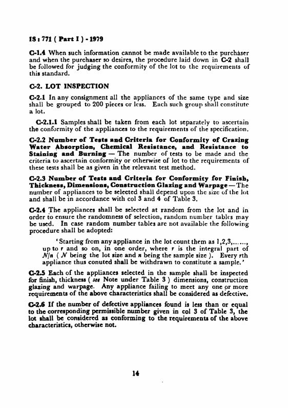
0-1.4 When such information cannot be made available to the purchaserand when the purchaser so desires, the procedure laid down in C-2 shallbe followed for judging the conformity of the lot to the requirements ofthis standard.
0.2. LOT INSPECTION
C-2.1 In any consignment all the appliances of the same type and sizeshall be grouped to 200 pieces or less. Each such group shall constitutea lot.
C-2.1.1 Samples shall be taken from each lot separately to ascertainthe conformity of the appliances to the requirements of the specification.
C-2.2 Namber of Te.t. aDd Criteria for CODformity of CraziDIWater ~b.orptioD, Chemical Resistance, and ResistaDce to5taiaiDg and BurDiDI - The number of tests to be made and thecriteria to ascertain conformity or otherwise of lot to the requirements ofthese tests shall be as given in the relevant test method.
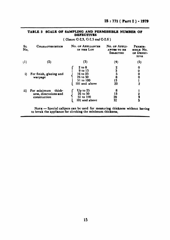
C-2.:J NUlDber or Teats aad Criteria for Conformity for Finish tThickDe••, DimeD.ioB_, CODstructioD GlaziDg and Warpage - Thenumber of appliances to be selected shall depend upon the size of the lotand shall be in accordance with col 3 and 4 of Table 3.
0.2.4 The appliances shall be selected at random from the lot and inorder to ensure the randomness of selection, random number tables maybe used. In case random number tables arc not available the followingprocedure shall be adopted:
C Starting from any appliance in the lot count them as 1,2,3, ,up to , and so on, in one order, where , is the integral part ofN/n ( N being the lot size and" being the sample size). Every rthappliance thus conuted shall be withdrawn to constitute a sample. '
0-2.5 Each of the appliances selected in the sample shall be inspectedfor finish, thickness ( se, Note under Table 3) dimensions. constructionglazing and warpage. Any appliance failing to meet anyone or morerequirements of the above characteristics shall be considered as defective.
C.Z.6 If the Dumber of defective appliances found is less than or equalto the corresponding permissible number given in col 3 of Table 3, thelot Ihall be considered al conforming to the requirements of the aboveeharacteristics, otherwise not.
It
IS : 771 ( Part I ) • 1979
TABLE 3 SCALB O' SAMPLING AND PERMISSIBLB NUMBER OPDEPECTIVaS
( Claus's C-2.3. C-2.5 Gnd C-2.6 )
SL CHARACTERISTICS No. OF ApPLIANCES No. 01' ApPLI- PERKI••No. IN Till: LOT Alf0B8 TO DB SIBLB No.
S.it.CTED 01' Dsrl:c-TIVII:
ll) (2) (3) (4) (5)
r 2 to 8 2 0I 9 to 15 3 0
i) For finish, glazing and t 16 to 25 5 0warpage < 26 to 50 8 0
l 51 to 100 13 1101 and above 20 2
ii) For minimum thick- r Up to 25 8 Iness, dimensions and 26 to 50 13 2construction < 51 to 100 20 3I
l 101 and above 32 5
NOTE - Special calipers can be used for meaaurinl thickness without haviogto break the appliance for ct.eckiDI the minimum tbickDeSl.
15
SvavlIYoa o. Woau ( NDZ )SJiaJ S. A. 'Il1BG.aJI
( C.tI,Uau,d from ,." 2 )M,,.,,,
SSKI S. P. C....aERABA.TI
I IS: 711 ( Part I ) • 1979
."".,.",CeDtr.1 Building Reae.reh In.titute (CSla).
RoorkeeTamil Nadu Water Supp1r It Drainale Board,
Madra. iCBID BNOINBD ( WATBB) Municipal Corporation of De1hi
ADDITIONAL CHIBI' ElfOJJfBaa( WATE. ) ( AI",.." )
CITY ENOINDB Bombay. Municipal CorporationDIBEOTOB Bombay Potteries at Tiles Ltd, Doluba,
SRBI A. M. KBIIBBAYI ( ~l""".',)· .SHBr M. K. GAIf.UL. Paraburam Pottery Worb Co Ltd. Thanpdb
SHIU R. M. J08BI ( ~"".." )SBBI B. R. N. GOPTA . Ministry of Defence
SKRl K. V. K1U8HNAJlUBTBY ( AltlFlldl, )SUBI M. T. KANa.' Directorate General of Supplies & Disposals,
New DelhiSaRI B. K. MALIlAJI In personal ~pacity (g]G;,. Mall. Road,NIUJ lHlld)SKal B. S. MIBcHA.DAm Phenoweld Polymer Private Limited, Bombay
SBal A. S. MIBOBA1fDAJlI ( ~llmttll, )SBRI D. ApPUKt1'rTA. NAIR PybUe Health EDliDeeriDl Department, Govern-
. ment of KeralaSSRI K. R.MACBAJlDUN ( AI",,,,,,, )
Saal B. J. PENTONY Ncjveli Ceramics It R.efractories Limited, VadalurSHill UIIATOBH SARKAR ( AlII_I,) ,r
SKat P.JAGANA'l'H RAO E. I. D.-Parry Ltd, Madr..SKMI M. Moo•• SULAllUJr (AI"'.',)
SaRI L. R. SaBGAL L. R. St>hgal &t Company, New DelhiS••I AMAL KUMAR 5.. Beugal Enamel Works Ltd, CalcuttaSIQU R. K. SOJIANY Hindu.tan Sanilaryware It IDdUitriea, Ltd,
BahadurprbCentral Public Works Department, New Delh'The ladian Institute of Architectl, HoIDbay
16
BUREAU OF INDIAN STANDARDS
HeadquartersManak Bhavan, 9 Bahadur Shah Zafar Marg, NEW DELHI 110002Telephones 323 0131, 323 3375, 323 9402Fax 91 11 3234062, 91 11 3239399, 91 11 3239382
32376 17
3378662
603843
23523 15
83292 95
Telegrams Manaksanstha(Common to ell Offices)
Telephone
8-770032
Centr.1 Laboratory
Plot No 20/9, Site IV, Sahibabad Industrial Area Sahibabad 201010
Regional Offices:
Central Manak Shavan, 9 Bahadur Shah Zafar Marg, NEW DELHI 110002
*Eastern 1/14 CIT Scheme VII M, V I P Road, Manlktola, CALCUTIA 700054
Northern SeQ 335·336, Sector 34-A, CHANDIGARH 160022
Southern CIT Campus, IV Cross Road, CHENNAI 600113
tWestern Manakalaya, E9, Behind Marol Telephone Exchange, Andhen (East),MUMBAI 400093
Branch Offlces::
'Pushpak', Nurmohamed Shaikh Marg, Khanpur, AHMEDABAD 380001
~Peenya Industrial Area, 1st Stage, Bangalore-Tumkur Road,BANGALORE 560058
Gangatfl Complex, 5th Floor, Bhadbhada Road, T T Nagar, BHOPAL 462003
Plot No 62-63, Unit VI, Ganga Nagar, BHUBANESHWAR 751001
Kalalkathlr BUildings, 670 Avmash: Road, COIMBATORE 641037
Plot No 43, Sector 16 A, Mathura Road, FARIDABAD 121001
Savrtn Complex, 116 G T Road, GHAZIABAD 201001
53/5 Ward No 29, R G Barua Road, 5th By-lane, GUWAHATI781003
5-8-56C, L N Gupta Marg, Nampally Station Road, HYDERABAD 500001
E-52, Chrtararuan Marg, C-Scheme, JAIPUR 302001
117/418 B. Sarvodaya Nagar, KANPUR 208005
Seth Shawan, 2nd Floor, Behind Leela Cinema, Naval Krshore Road,LUCKNOW 226001
NIT BUilding, Second Floor, Gokulpat Market, NAGPUR 440010
Pathputra Industrial Estate, PATNA 800013
Institution of Engineers (India) Budding 1332 ShivaJI Nagar, PUNE 411005
T e No 14/1421, University P 0 PaJayam, THIAUVANANTHAPURAM 695034
550 13 48
8394955
554021
403627
21 01 41
8-288801
8-71 1996
54 11 37
20 1083
372925
21 6876
238923
52 51 71
262305
323635
621 17
*Sales Office IS at 5 Chownnghee Approach, P 0 Pnncep Street,CALCUTIA 700072
tSales Office IS at Novelty Chambers, Grant Road, MUMBAI 400007
~Sales Office IS at 'F' Block, Unity BUilding Narashlmarsl8 Square,BANGALOAE 560002
27 1085
3096528
222 397\
Printed ..at Pnntogreph, New Delhi, Ph j 12()b47