IS 6938 (2005): Design of rope drum and chain hoists for ... · is 6938:2005 ~&h-?+fl-afawat design...
19
Disclosure to Promote the Right To Information Whereas the Parliament of India has set out to provide a practical regime of right to information for citizens to secure access to information under the control of public authorities, in order to promote transparency and accountability in the working of every public authority, and whereas the attached publication of the Bureau of Indian Standards is of particular interest to the public, particularly disadvantaged communities and those engaged in the pursuit of education and knowledge, the attached public safety standard is made available to promote the timely dissemination of this information in an accurate manner to the public. इंटरनेट मानक “!ान $ एक न’ भारत का +नम-ण” Satyanarayan Gangaram Pitroda “Invent a New India Using Knowledge” “प0रा1 को छोड न’ 5 तरफ” Jawaharlal Nehru “Step Out From the Old to the New” “जान1 का अ+धकार, जी1 का अ+धकार” Mazdoor Kisan Shakti Sangathan “The Right to Information, The Right to Live” “!ान एक ऐसा खजाना > जो कभी च0राया नहB जा सकता ह ै” Bhartṛhari—Nītiśatakam “Knowledge is such a treasure which cannot be stolen” IS 6938 (2005): Design of rope drum and chain hoists for hydraulic gates - Code of practice [WRD 12: Hydraulic Gates and Valves]
Transcript of IS 6938 (2005): Design of rope drum and chain hoists for ... · is 6938:2005 ~&h-?+fl-afawat design...

Disclosure to Promote the Right To Information
Whereas the Parliament of India has set out to provide a practical regime of right to information for citizens to secure access to information under the control of public authorities, in order to promote transparency and accountability in the working of every public authority, and whereas the attached publication of the Bureau of Indian Standards is of particular interest to the public, particularly disadvantaged communities and those engaged in the pursuit of education and knowledge, the attached public safety standard is made available to promote the timely dissemination of this information in an accurate manner to the public.
इंटरनेट मानक
“!ान $ एक न' भारत का +नम-ण”Satyanarayan Gangaram Pitroda
“Invent a New India Using Knowledge”
“प0रा1 को छोड न' 5 तरफ”Jawaharlal Nehru
“Step Out From the Old to the New”
“जान1 का अ+धकार, जी1 का अ+धकार”Mazdoor Kisan Shakti Sangathan
“The Right to Information, The Right to Live”
“!ान एक ऐसा खजाना > जो कभी च0राया नहB जा सकता है”Bhartṛhari—Nītiśatakam
“Knowledge is such a treasure which cannot be stolen”
“Invent a New India Using Knowledge”
है”ह”ह
IS 6938 (2005): Design of rope drum and chain hoists forhydraulic gates - Code of practice [WRD 12: HydraulicGates and Valves]


IS 6938:2005
~&h-?+Fl-afaWaT
DESIGN OF ROPE DRUM AND CHAIN HOISTS FORHYDRAULIC GATES — CODE OF PRACTICE
(Second Revision )
ICS 93.160
.
Q BIS 2005
BUREAU OF INDIAN STANDARDSMANAK BHAVAN, 9 BAHADUR SHAH ZAFAR MARG
NEW DELHI 110002
November 2005 Price Group 7
Hydraulic Gates and Valves Sectional Committee, WRD 12
FOREWORD
This Indian Standard ( Second Revision) was adopted by the Bureau of Indian Standards, afier the draft finalizedby the Hydraulic Gates and Valves Sectional Committee had been approved by the Water Resources DivisionCouncil.
Controlled release of water from reservoirs is made by the use of spillway gates provided on crests, control gatesin conduits or in the body of the dam and tunnels. For the operation of these gates, various types of mechanismsare provided. The rope drum and chain hoists are used for gates which close by their own weight and where nopositive thrust is required to close them.
in the formulation of this standard, due weightage has been given to international co-ordination among thestandards and practices prevailing in different countries in addition to relating it to the practices in the fieldin this country.
This standard was first published in 1973 and subsequently revised in 1989. In this revision the requirementsof motors, hoist limit switch, control panel and figures have been modified in the light of experience gained overthe years,
The composition of the Committee responsible for the formulation ofthis standard is given in Annex B.
For the purpose of deciding whether a particular requirement of this standard is complied with, the finalvalue, observed or calculated expressing the result of a test or analysis, shall be rounded off in accordance withIS 2:1960 ‘Rules for rounding off numerical values ( revised )’. The number of significant places retarned in therounded off value should be the same as that of the specified value in this standard.
. .

1S 6938:2005
Indian Standard
DESIGN OF ROPE DRUM AND CHAIN HOISTS FORHYDRAULIC GATES — CODE OF PRACTICE
(Second Revision )1 SCOPE
This standard lays down guiding principles for designof rope drum and chain hoists used for the operationof hydraulic gates.
2 REFERENCES
The standards listed in Annex.A contain provisions,which through reference in this text, constituteprovisions of this standard. At the time of publication,the editions indicated were valid. All standards aresubject -to revision and parties to agreements-basedon this standard are encouraged to in-vestigatethe possibility of applying the most recent editionsof the standards indicated in Annex A.
3 GENERAL
3.1 Hoist Capacity
3.1.1 The hoist capacity shall be determined by takinginto consideration the following forces which mightbe required to overcome:
a)
b)
c)
d)
e)
o
Weight of the gate along with all itscomponents including the weight of wire ropeand its attachments and ballast, if any;
All frictional forces comprising of
1) Wheel friction,
2) Guide friction, and
3) Seal friction including friction due toinitial interference;
Any hydrodynamic load, like downpull/upliftforce, etc;
Silt and ice load wherever encountered;
Weight of lifting beam, if used; and
Any other consideration specific to aparticular site.
3.1.2 The worst combination of the above forces,during either lowering cycle or raising cycle, shall beconsidered.
3.1.3 The hoist capacity thus arrived at shall beincreased by 20 percent to CMW r“or the reservehoist capacity unless otherwise specified by thepurchaser.
3.1.4 The gate shall be designed for closing underits self weight ( without any positive thrust to the
same ) and the downward forces closing the. gatewhile lowering shail be at least 20 percent higherthan the frictional and other forces opposing thedownward motion. The necessary closing/seatingload shall be calculated considering the net cross-sectional area of the bottom seal and maximum waterpressure acting on it such that the lowering force ismore than the seating load. However, the values ofclosingkeating load shall be greater than those givenbelow:
Type of Gate Minimum Seating Load
Low head gates 2.5 kN/m length of gate
Medium head gates 5.0 kN/m length of gate
High head gates 10.0 kN/m length of gate
3.1.5 The usual operating speed for such hoist shallbe 300 to 700 mm/min. However, higher values maybe adopted depending upon the requirements.
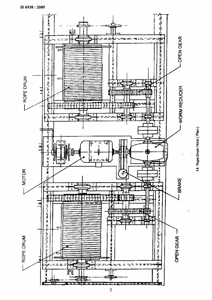
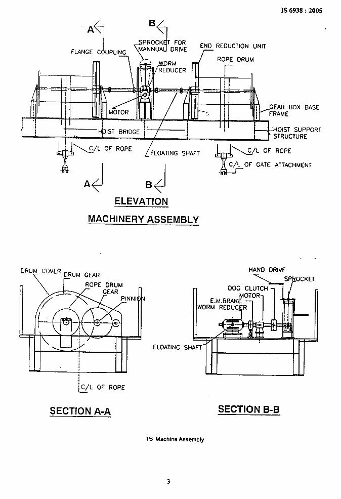
Typical hoisting arrangements for operation of variousgates are shown in Fig. 1 and Fig. 2. ‘
4 DESIGN OF MECHANICAL PARTS
4.1 General Requirements
4.1.1 The various components of hoist mechanismshall be so proportioned as to take the worst “loadcoming on individual component.
4.1.2 The stress in various components of hoistshall be checked for maximum power transmissionin these components, taking into account thepermissible stresses as given in reIevant clauses.Various structural and mechanical components ofhoist shall also be checked for breakdown torque ofthe motor.
4.1.3 All the hoisting machinery parts shall be checkedfor static as well as dynamic loads.
4.1.4 The combined stress in each component shallbe found by the following formula:
CTc= J(71~+c+71f32+3$
where
cc =
Cr,C* =
‘r .
combined stress, in N/mm2;
tensile/compressive stresses, in N/mz;and
torsional shear stress, in N/mmz.
1
IS 6938:2005
2
i?a
%oIx
I/
II
LEfe=+---’”-’--”-”*
L
h----l-i-t!1
&I
.,
( II I
,-1 11
1,
I
II
III
It,
I I
I
v vh
----- ----
u
5c!)
‘?
2
B‘+
IS 6938:2005
.
(JFLANGE C UPLtNG
W
GEAR BOX BASE
I FRAME
<fPROCK FOR
MANNUA DRIVE
1
‘~ )YJIRM-~ /REDuCER
Iti
END REDUCTION UNIT
k
ROPE DRUM
r—z .—-.
I
‘ OIST SUPPORT
ELEVATION
MACHINERY ASSEMBLY
‘Ru~ cOvER~RUM GEAR
\C/L OF ROPE.—
FLOATING
HAND DRIVE
% SPROCKET
SH
SECTION A-A SECTK)N B-B
IB Machine Asserrtbly
3

SPROCKET FOR
r
MANUAL DRIVE
FLANGE COUPLING ‘rEND REDUCTION UNIT
/41kb-------- - ----
Ill \\ 1 ,TOP SHEAVER=4Fl(!llHml-M \
—4 GEAR BOX BASE
FRAMEI I 1 I . ~l!.J, 11~~
I,
iil!~!. 1
4‘ ji
~HOIST BRIDGE+ HOIST SUhY)RTI !i: gn STRU(TURE
------ ------ ------ ------ ------ .-..
II. .
I
i
SHEAVE i~ I
i~i
I ;;
i !!
i !!
a
i f.
GATE SHEAVE w
i! I
ELEVATION f i
!! i
MACHINERY ASSEMBLY it.
G
w
.
GATE SHEAVE
1C Gate Attachment with Balancing Sheave Assembly
FIG. 1 TYPICALHOISTINGARRANGEMENTSOFGATES

IS6938:2005
3n
mvL
5
IS 6938:2005
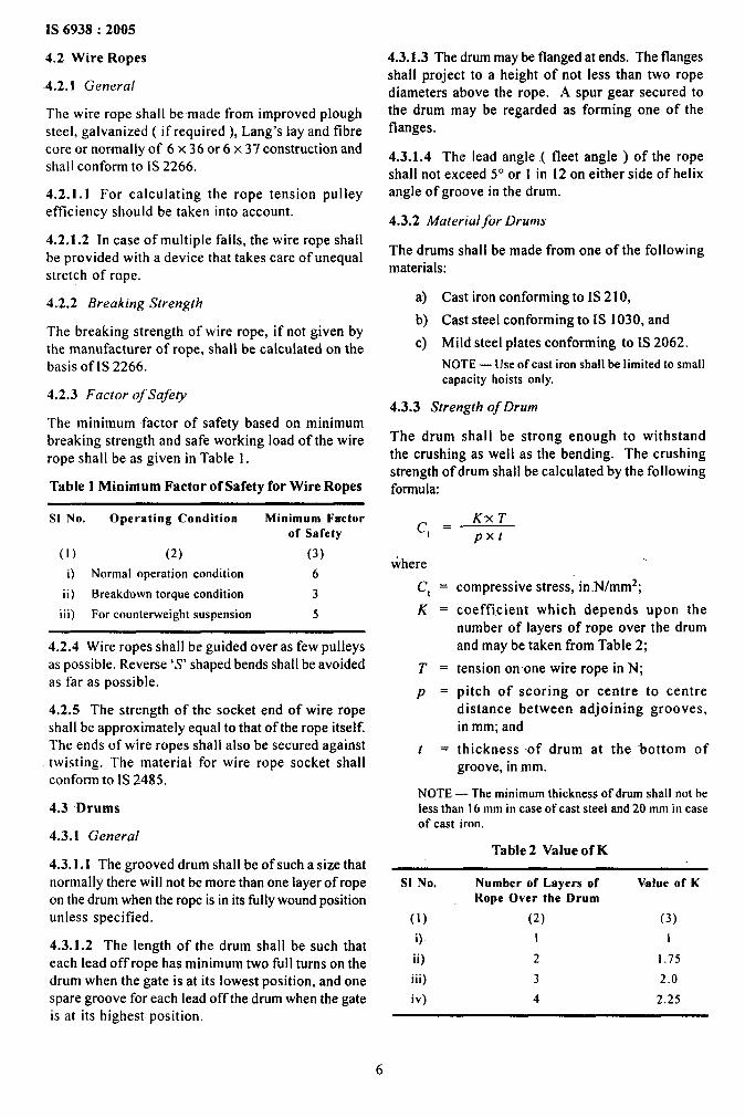
4.2 Wire Ropes
4.2.1 General
The wire rope shall bemade from improved ploughsteel, galvanized ( if required ), Lang’s lay and fibrecore or normally of 6 x 36 or 6 x 37 construction andshall conform to 1S2266.
4.2.1.1 For calculating the rope tension pulleyefficiency should be taken into account.
4.2.1.2 In case of multiple falls, the wire rope shallbe provided with a device that takes care of unequalstretch of rape.
4.2.2 Breaking Strength
The breaking strength of wire rope, if not given bythe manufacturer of rope, shall be calculated on thebasis of IS 2266.
4.2.3 Factor of Safety
The minimum factor of safety based on minimumbreaking strength and safe working load of the wirerope shall be as given in Table 1..
Table 1 Minimum Factor of Safety for Wire Ropes
4.3.1.3 The drum may be flanged at ends. The flangesshall project to a height of not less than two ropediameters above the rope. .4 spur gear secured tothe drum may be regarded as forming one of theflanges.
4.3.1.4 The lead angle.( fleet angle ) of the ropeshall not exceed 5° or”1 in 12 on either side of helixangle of groove in the drum.
4.3.2 A4aterialfor Drums
The drums shall be made from one of the followingmaterials:
a) Cast iron conforming to IS21 0,
b) Cast steel conforming to IS 1030, and
c) Mild steel plates conforming to [S 2062.
NOTE — Use of cast iron shall be limited to small
capacity hoists only.
4.3.3 Strength of Drum
The drum shall be strong enough to -withstandthe crushing as well as the bending. The crushingstrength of drum shall be calculated by the followingformula:
S1 No. Operating Condition Minimum Fxctorof Safety
(1) (2) (3)
i) Normal operation condition 6
ii) Breakdown torque condition 3
iii) For counterweight suspension 5
4.2.4 Wire ropes shall be guided over as few pulleysas possible. Reverse ‘S’ shaped bends shall be avoidedas far as possible.
4.2.5 The strength of the socket end of wire ropeshall be approximately equal to that of the rope itself.The ends of wire ropes shall also be secured against
. twisting. The material for wire rope socket shallconform to 1S2485.
4.3 Drums
4.3.1 General
4.3.1.1 The grooved drum shall.be of such a size thatnormally there will not be more than one layer of ropeon the drum when the rope is in its filly wound positionunless specified.
4.3.1.2 The length of the drum shall be such thateach lead off rope has minimum two full turns on thedrum when the gate is at its lowest position, and onespare groove for each lead off the drum when the gateis at its highest. position.
f’.Kx T
‘t
wherec, =
K=
T=
P=
t .
pxt
.
compressive stress, in N/mm2;
coefficient which depends upon thenumber of layers of rope over the drumand may be taken from Table 2;
tension on one wire rope in N;
pitch of scoring or centre to centredistan-ce between adjoining grooves,in mm; and
thickness of drum at the “bottom ofgroove, in mm.
NOTE — The minimum thickness of drum shall not beless than 16 mm in case of cast steel and 20 mm in caseof cast iron.
Table 2 Value Qf K
S1 No. Number of Layers of Value of KRope Over the Drum
(1) (2) (3)
0 I 1
ii) 2 1.75
iii) 3 2.0
iv) 4 2.25
6
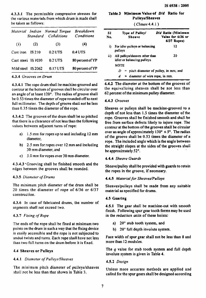
4.3.3.1 The permissible compressive stresses forthe various materials from which drum is made shall
be taken as follows:
Material Indian Normal Torque BreakdownStandard Conditions Conditions
(1) (2) (3) (4)
Cast iron IS 210 0.2 UTS 0.4 UTS
Cast steel IS 1030 0.2 UTS 80 percentof YP
Mild steel 1S 2062 0.17 UTS 80 percentof YP
4.3.4 Grooves on Drum
4.3.4.”1 The rope drum shall be machine-grooved andcontour at the bottom of grooves shall be circular overan angle of at least 120°. The radius of groove shallbe 0.53 times the diameter of rope rounded off to nextfull millimeter. The depth of groove shall not be lessthan 0.35 times the diameter of the rope.
4.3.4.2 The grooves of the drum shall be so pitchedthat there is a clearance of not less than the followingvalues between adjacent turns of rope:
a)
b)
c)
1.5 mm for ropes up to and including 12 mmdiameter,
2.5 mm for ropes over 12 mm and including30 mm diameter, and
3.0 mm for ropes over 30 mm diameter.
4.3,4.3- Grooving shall be finished smooth and theedges between the grooves shall be rounded.
4.3.5 Diameter of Drums
The minimum pitch diameter of the drum shall be20 times the diameter of rope of 6/36 or 6/37construct ion.
4.3.6 In case of fabricated drums, the number ofsegments shall not exceed two.
4.3.7 Fixing of Rope
The ends of the rope shall be fixed at minimum twopoints on the drum in such a way that the fixing deviceis easily accessible and the rope is not subjected toundue twists and turns. Each rope shall have not lessthan two full turns on the drum before it is fixed.
4.4 Sheaves or Pulleys
4.4.1 Diameter of Pulley.v/Sheaves
The minimum pitch diameter of pulleys/sheavesshall not be less than that shown in Table 3.
7
IS 6938:2005
Table 3 Minimum Value of D/d Ratio forPulleys/Sheaves
( Clause 4.4.l )
sl Type of Pulley/ D/d Ratio (Minimum‘No. Sheave Value for 6/36 -or
6/37 Ropes)
i) For idler pulleys or balancing 12
pulleys
ii) All pulleyskheaves other than 20idler or balancing pulleys
NOTE
-D = pitch diameter of pulley, in mm; and
d = diameter of wire rope, in mm.
4.4.2 The diameter at the bottom of the grooves ofthe equivalizing sheaves shall be not less than62 percent of the minimum pulley diameter.
4.4.3 Grooves
Sheaves or pulleys shall be machine-grooved to adepth of not less than 1.5 times the diameter of therope. Grooves shall be finished smooth and shall befree from surface defects likely to injure rope. Thecontour at the bottom of the grooves shall be circuiarover an angle of approximately 130° * 5°. The radiusof the groove shall be 0.53 times the diameter of arope. The included angle which is-the angle betweenthe straight slopes at the sides of the grooves shallbe approximately 52°.
.
4.4.4 Sheave Guara%
Sheavelpulley shall be provided with guards to retainthe ropes in the groove, if necessary.
4.4.5 Material for Sheaves/Pulleys
Sheaves/pulieys shall be made from any suitablematerial asspecified for drums.
4.5 Gearing
4.5.1 The gear shall be machine-cut with smoothfinish. Following spur gear tooth forms may be usedin the reduction units of these hoists:
a) 20° stub tooth System, and
b) 20° full depth involute system.
Face width of spur gear shall not be less than 8 andmore than 12-modules.
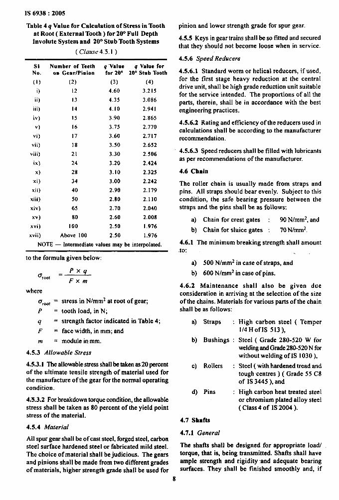
The q value for stub tooth system and full depthinvolute system is given in Table 4.
4.5.2 Design
Unless more accurate methods are apptied andcalled for the spur gears-shall be designed according
IS 6938:2005
Table 4 q Value for Calculation of Stress in Toothat Root ( External Tooth) for 20° Full Depth
-Involute System and 20° Stub Tooth Systems
( Clause 4.5.l )
SI Number of Teeth q -value q Value forNo. on Gear/Pinion for 20” 20° Stub Tooth
(1) (2) (3) (4)
i) 12 4.60 3.215
ii) 13 4.35 3.086
iii) 14 4.10 2.941
iv)
v)
vi)
vii)
viii)
ix)
x)
xi)
xii)
15
16
17
18
21
24
28
34
40
3.90
3.75
3.60
3.50
3.30
3.20
3.10
3.00
2.90
2.865
2.770
2.717
2.652
2.506
2.424
2.325
2.242
2.179
xiii) 50 2.80 2.110
xiv) 65 2.70 2.040
xv) 80 2.60 2.008
xvi) I 00 2.50 1.976
xvii) Above 100 2.50 1.976
NOTE — Intermediate values may be interpolated.
to the formula given below:
. Pxq0 root
Fxrn
where
0 root = stress in N/mm* at root of gear;
P = tooth load, in N;
q = strength factor indicated in Table 4;
F = face width, in mm; and
m = module in mm.
4.5.3 Allowable Stress
4.5.3.1 The allowable stress shall be taken as 20 percentof the ultimate tensile strength of material used forthe manufacture of the gear for the normal operatingcondition.
4.-5.3.2 For breakdown torque condition, the allowablestress shall be taken as 80 percent of the yield pointstress of the material.
4.5.4 Material
All spur gear shall be of cast steel, forged steel, carbonsteel surface hardened steel or fabricated mild steel.The choice of material shall be judicious. The gearsand pinions shall be made from two different gradesof materials, higher strength grade shall be used for
8
pinion and lower strength grade for spur gear.
4.5.5 Keys in gear trains shall be so fitted and secu~edthat they should not become loose when in service.
4.5.6 Speed Reducem
4.5.6.1 Standard worm or helical reducers, if used,for the first stage heavy reduction at the centraldrive unit, shall be high grade reduction unit suitablefor the service intended. The proportions of all theparts, therein, shall be in accordance with the bestengineering practices.
4.5.6.2 Rating and efficiency of the reducers used incalculations shall be according to the manufacturerrecommendation.
4.5.6.3 Speed reducers shall be filled with lubricantsas per recommendations of the manufacturer.
4.6 Chain
The roller chain is usually made from straps andpins. All straps should bear evenly. Subject to thiscondition, the safe bearing pressure between thestraps and the pins shall be as folIows:
a) Chain for crest gates : 90 N/mm*, and
b) Chain for sluice gates : 70 Nhnrn2.
4.6.1 The minimum breaking strength shall amountto: . .
a) 500 N/mm* in case of straps, and
b) 600 N/mm* in case of pins.
4.6.2 Maintenance shall also be given dueconsideration in arriving at the selection of the sizeof the chains. Materials for various~arts of the chainshall be as follows:
a) Straps :
b) Bushings :
c) Rollers
d) “Pins
High carbon steel ( Temper1/4 HofIS 5L3 ),
Steel ( Grade 280-520 W forweldingand Grade 280-520 N forwithout welding of.IS 1030),
‘Steel ( with hardened tread andtough centres ) ( Grade 55 C8of 1S3445), and
High carbon heat treated steelor chromium plated alloy steel(Class 4 of IS 2004 ).
4.7 Shafts
4.7.1 General
The shafts shall be designed for appropriate load/torque, that is, being transmitted. Shafis shall haveample strength and rigidity and adequate bearingsurfaces. They shall be finished smoothly and, if
shouldered, shall be provided with fillets of large
radius.
4.7.2 Dimensioning of Shafts
In dimensioning the shaft with ratio ( length/diameter ) 2 50, the angle of twist and therevolutions/minute shall be taken into account, inaddition to simple bending, pure torsion, or thecombined effect of bending and torsion. The twistthat shall be permitted is 1/4° to 1/3° per m. Lineardeflection in the shaft shall not exceed 1 mm/mof length.
4.7.3 Material
All shafts shall be of forged/rolled steel.
4.7.4 Allowable Stress
The allowable stress for solid shaft shall be as follows:
a)
b)
c)
Maximum allowable bending stress, ( -Ub)either in tension or compression only
‘b = 0.5 yield point or 20 percent of ultimatestrength whichever is less.
Maximum allowable torsional shear stress(r)
T = 30 percent of the yield point stress.
Combined stress shall be calculated with thefollowing formula and shall not be greaterthan that at (a) above
where
‘c ‘4 crb*+ 31J
combined stress, in N/mm* and shallnot exceed 0.24 UTS or 0.60 YP,whichever is less;
tensile/compressive stress, in N/mm*;and
shear stress, in N/mm*.
The allowable stress for shafts with keys shall be75 percent of the above value.
The shatl shall also be designed for combined bendingand twisting by making use of the following formulaeand shall be checked for breakdown torque condition.For breakdown torque condition, the allowable stressshall be taken as 80 percent of the yield point stressof the.material except for shear for which value sha[lbe limited in the ratio of permissible stress under normalconditions. The equivalent bending and twistingstress shall not exceed 1.2 times the maximumallowable stress as at 4.7.4 (a) and 4.7.4(b) separately.
1) Bending
Me = 0.5( Iu+Jm
IS 6938:2005
2) Twisting:
whereMe =
M=
T=
< .=
equiva-lent bending moment, inNm;
bending moment, in Nm;
twisting moment, in Nm; and
equivalent twisting moment, in Nm.
4.8 Bearings
4.8.1 Types of Bearing
All the running shatls shall be provided with ball,roller or bush bearings. Selection of bearings shallbe done on consideration of duty, load and-speed ofthe shaft.
4.8.1.1 Life of ball and roller bearings shall becalculated in accordance with the maufacturer’srecommendations.
4.8.1.2 Bearings shall be easily accessible forlubrication and/or replacement. If there is more thanone bearing on one shaft, every bearing shall beprovided with individual lubrication arrangement.
4.8.-1.3 The minimum thickness of bronze bush shallbe calculated by the following formula:
t=O:08 d+3 mm .,
where
d = diameter of the shafl, in mm; and
t = thickness of bush, in mm.
NOTE— Allowable bearing streaa in case of bronze“bush shall be as per Annex B of IS 4622. However,in case of breakdown torque condition it may beincreased by “33 I/3 percent.
4.9 Couplings
4.9.1 Material
All couplings shall be of forged steel or cast steeland shall be designed to transmit the maximum torquethat may be developed.
4.9.2 Solid couplings shall be aligned in such awaythat they meet accurately. Flexible couplings shallbe initially aligned with-the same accuracy as solidcouplings.
4.9.3 Flexible couplings shall be fitted between motorshafts and extension shafts.
4.10 Gear Boxes
4.10.1 Gear boxes shall be of rigid construction fittedwith inspection covers and Iifling handles wherenecessary. The gear boxes shall be so designed that
9
IS 6938:2005
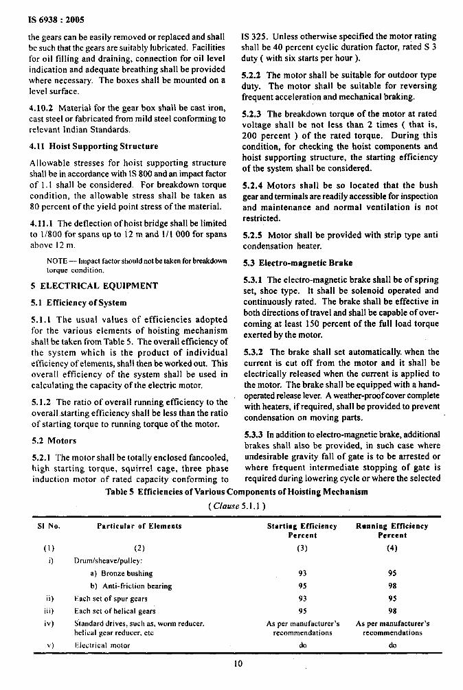
the gears can be easily removed or replaced and shallbe such that the gears are suitably lubricated. Facilitiesfor oil tilling and draining, connection for oil levelindication and adequate breathing shall be provided
where necessary. The boxes shall be mounted on alevel surface.
4.10.2 Material for the gear box shalI be cast iron,cast steel or fabricated from mild steel conforming torelevant Indian Standards.
4.11 Hoist Supporting Structure
Allowable stresses for hoist supporting structureshall be in accordance with 1S800 and an impact factorof 1.1 shall be considered. For breakdown torquecondition, the allowable stress shall be taken as80 percent of the yield point stress of the material.
4.11.1 The deflection of hoist bridge shall be limitedto 1/800 for spans up to 12 m and 1/1 000 for spansabove 12 m.
NOTE — Impact factor should not be taken for breakdowntorque condition.
5 ELECTRICAL EQUIPMENT
5.1 Efficiency of System
5.1.1 The usual values of efficiencies adoptedfor the various elements of hoisting mechanismshal Ibe taken from Table 5. The overall etliciency ofthe system which is the product of -individualefficiency of eiements, shall then be worked out. Thisoverall efficiency of the system shall be used incalculating the capacity of the electric motor.
5.1.2 The ratio of overall running efficiency to theoverall-starting efficiency shall be less than the ratioof starting torque to running torque of the motor.
5.2 Motors
5.2.1 The motor shall be totally enclosed fancooled,high starting torque, squirrel cage, three phaseinduction motor of rated capacity conforming to
IS 325. Unless otherwise specified the motor ratingshall be 40 percent cyclic duration factor, rated S 3duty ( with six starts per hour).
5.2.2 The motor shall be suitable for outdoor typeduty. The motor shall be suitable for reversingfrequent acceleration and mechanical braking.
5.2.3 The breakdown torque of the motor at ratedvoltage shall be not less than 2 times ( that is,200 percent ) of the rated torque. During-thiscondition, for checking the -hoist components andhoist supporting structure, the starting efficiencyof the system shall be considered.
5.2.4 Motors shaIl ‘be so located that the bushgear and terminals are readily accessible for inspectionand maintenance and normal ventilation is not-restricted.
5.2.5 Motor shall be provided with strip type anticondensation heater.
5.3 Etectro-magnetic Brake
5.3.1 The electro-magnetic brake shall be of springset, shoe type. It shall be solenoid operated andcontinuously rated. The brake shall be effective inboth directions of travel and shall be capable of over-coming at least 150 percent of the full load torqueexerted by the motor.
5.3.2 The brake shall set automatically when thecurrent is cut off from the motor and it shall beelectrically released when the current is applied tothe motor. The brake shall be equipped with a hand-operated release lever, A weather-prtif cover completewith.heaters, if required, shall be provided to preventcondensation on moving parts.
5.3.3 In addition to electro-magnetic brake, additionalbrakes shall also be provided, in such case whereurtdesirable gravity fall of gate is to be arrested orwhere frequent intermediate stopping of gate isrequired during lowering cycle or where the selected
Table 5 Efficiencies of Various Components of Hoisting Mechanism
( Clause 5.1.1)
S1 No. Particular of Elements
(1) (2)
i) Drum/sheave/pulley:
a) Bronze bushing
b) Anti-friction bearing
ii) Each set of spur gears
iii) Each set of helical gears
iv) S“tandarddrives, such as, worm reducer,helical gear reducer. etc
v) Electrical motor
Starting EfficiencyPercent
(3)
93
95
93
95
As per manufacturer’srecommendations
do
Rwnning EfficiencyPercent
(4)
95
98
95
98
As per manufacturer’srecommendations
do
10
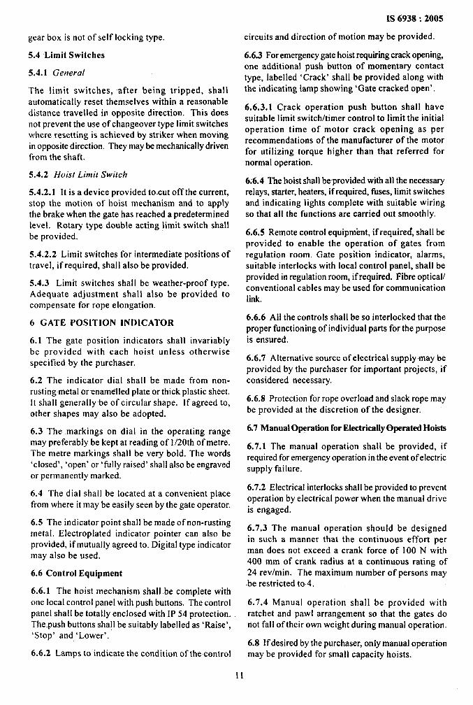
gear box is not of self locking type.
5.4 Limit Switches
5.4.1 General
The limit switches, after being tripped, shallautomatically reset themselves within a reasonabledistance travelled in opposite direction, This doesnot prevent the use of changeover type limit switcheswhere resetting is achieved by striker when movingin opposite direction. They maybe mechanically drivenfrom the shaft.
5.4.2 Hoist Limit Switch
5.4.2.1 It is a device provided to.cut off the current,stop the motion of hoist mechanism and to applythe brake when the gate has reached a predeterminedlevel. Rotary type double acting limit switch shallbe provided.
5.4.2.2 Limit switches for intermediate positions oftravel, if required, shall also be provided.
5.4.3 Limit switches shall be weather-proof type.Adequate adjustment shall also be provided tocompensate for rope elongation.
6 GATE POSITION INDICATOR
6.1 The gate position indicators shall invariablybe provided with each hoist unless otherwisespecified by the purchaser.
6.2 The indicator dial shall be made from non-rustingmetal or~namelled plate or thick plastic sheet.It shall generally-be of circular shape. If agreed to,other shapes may also be adopted.
6.3 The markings on dial in the operating rangemay preferably be kept at reading of 1/20th of metre.The metre markings shall be very bold. The words‘closed’, ‘open’ or ‘fully raised’.shall also be engravedor permanently marked.
-6.4 ‘The dial shall be located at a convenient placefrom where it maybe easily seen by the gate operator.
6.5 The indicator point shall be made of non-rustingmetal. Electroplated indicator pointer can also b-eprovided, if mutually agreed to. Digital type indicatormay also be used.
6.6 Control Equipment
6.6.1 The hoist mechanism shall be complete withone local control panel with push buttons, The controlpanel shall be totally enclosed with 1P54 protection.The.push buttons shall be suitably labelled as ‘Raise’,‘Stop’ and ‘Lower’.
6.6.2 Lamps to indicate the condition of the control
IS 6938:2005
circuits and direction of motion maybe provided.
6.6.3 For emergency gate hoist requiring crack opening,one additional push button of momentary contacttype, labelled ‘Crack’ shall be provided along withthe indicating lamp showing ‘Gate cracked open’.
6.6.3.1 Crack operation push button shall havesuitable limit switch/timer control to limit the initialoperation time of motor crack opening as perrecommendations of the manufacturer of the motorfor utilizing torque higher than that referred fornormal operation.
6.6.4 The hoist shall be-provided with all the necessaryrelays, starter, heaters, if required, fises, limit switchesand indicating lights complete with suitable wiringso that all the functions are carried out smoothly.
6.6.5 Remote control equipment, ifrequirecf, shall beprovided to enable the operation of gates fromregulation roam. Gate position indicator, alarms,suitable interlocks with local control panel, shall beprovided in regulation room, if required. Fibre optical/conventional cables may be used for communicationlink.
“6.6.6 All the controls shall be so interlocked that theproper functioning of individual parts for the purposeis ensured.
6.6.7 Alternative source of electrical supply+nay beprovided by the purchaser for important projects, ifconsidered necessary.
6.6.8 Protection for rope overload and slack rope maybe provided at the discretion of the designer.
6.7 Manual Operation for EleetricallyOperated Hoists
6.7.1 The manual operation shall be provided, ifrequired for emergency operation in.theevent of electricsupply failure.
6.7.2 Electrical interlocks shall be provided to preventoperation by electrical power when the manual driveis engaged.
6.7.3 The manual operation should be designedin such a manner that the continuous effort perman does not exceed a crank force of 100 N with400 mm of crank radius at a continuous rating of24 rev/rein. The maximum number of persons maybe restricted to 4.
6.7.4 Manual operation shall be provided withratchet and pawl arrangement so that the gates donot fall of their own weight during manual operation.
6.8 If desired by the purchaser, only manual operationmay be provided for small capacity hoists.
11
IS 6938:2005
IS No.
210:1993
325:1996
513:1994
800:1984
1030:1998
2004:1991
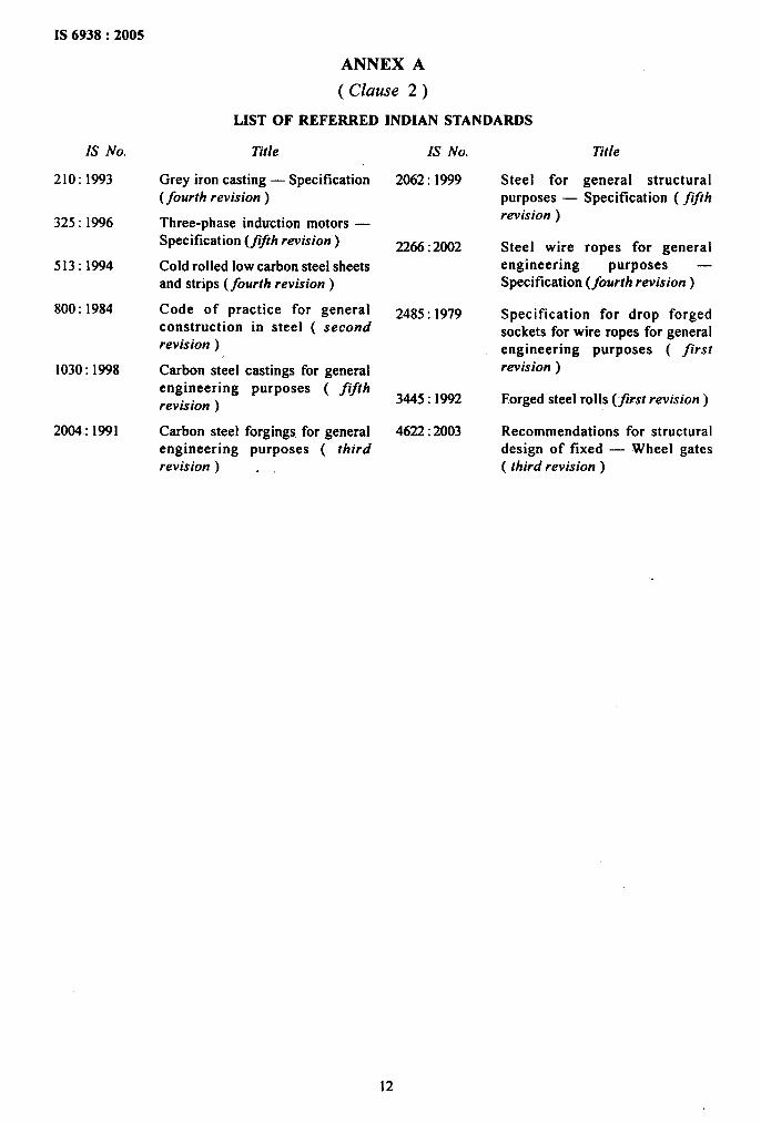
ANNEX A
(Clause 2)
LIST OF REFERRED INDIAN STANDARDS
Title
Grey iron casting — Specification(fourth revision )
Three-phase induction motors —‘Specification (flJth revision)
Cold rolled low carbon steel sheetsand strips (fourth revision )
Code of practice for generalconstruction in steel ( secondrevision _)
Carbon steel castings for generalengineering purposes ( fifthrevision )
Carbon steel forgings for generalengineering purposes ( thirdrevision ) .
IS No.
2062:1999
2266:2002
2485:1979
3445:1992
4622:2003
Stee! forpurposes —revision )
Steel wire
Title
general structuralSpecification ( fifth
ropes for generalengineering purposes —Specification (fourth revision )
Specification for drop forgedsockets for wire ropes for generalengineering purposes ( firstrevision )
Forged steel rolls (first revision )
Recommendations for structuraldesign of fixed — Wheel gates( third revision)
12
IS 6938:2005
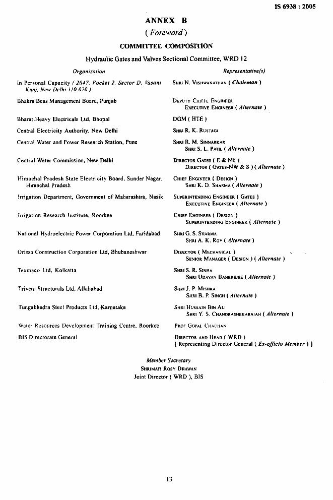
ANNEX B
( Foreword)
COMMITTEE COMPOSITION
Hydraulic Gates and Valves Sectional Committee, WRD 12
Organization
In Personal Capacity ( 2047, Pocket 2, Sector D, Vasant
Kunj, New Delhi 110 070)
Bhakra Beas Management Board, Punjab
Bharat Heavy Electrical Ltd, Bhopal
Central Electricity Authority, New Delhi
Central Water and Power Research Station, Pune
Central Water Commission, New Delhi
Himachal Pradesh State Electricity Board, Sunder Nagar,Himachal Pradesh
Irrigation Department, Government of Maharashtra, Nasik
Irrigation Research Institute, Roorkee
“National Hydroelectric Power Corporation Ltd, Faridabad
Orissa Construction Corporation Ltd, Bhubaneshwar
Texmaco Ltd, Kolkatta
Triveni Structural Ltd, Allahabad
Tungabhadra Steel Products Ltd, -Karnataka
Water Resources Development Training Centre, Roorkee
BIS Directorate General
Representative(s)
SHRIN. VISHWANATHAN( Chairman )
DEPUTY CHIEFE ENGINEEREXECUTIVEENGINEER( Alternate )
DGM ( HTE )
SHIU R. K. RUSTACiI
SHRIR. M. SINNARKARSHRI S, L. PATIL( Alternate )
DIRECTORGATES( E &NE)DIRECTOR( GATES-NW& S ) ( Alternate)
CHIEF ENGINEER( DESIGN )SHRI K. D. SHARMA( Alternate )
SUPERINTENDINGENGINEER( GATES)EXECUTIVEENGINEER( Alternate )
CHIEF ENGINEER( DESIGN )SUPERINTENDINGENGINEER( Alternate )
SHRIG. S. SHAFtMASHRI A. K. Rov ( Alternate )
DIRECTOR( MECHANICAL) .
SENIORMANAGER( DESIGN ) ( Alternate )
SHRI S. R. SINHASHRI UDAYANBANEREJEE( Alternate )
SHRI J. P. MISHRASHRI B. P. SINGH( Alternate )
SHRI HUSSAINBIN ALISHRI Y. S. CHANDRASHEKARAIAH( Alternate )
PROFGOPALCHAU~AN
DIKECTORAND HEAO ( WRD )[ Representing Director General ( Ex-of&cio Member ) ]
Member Secretary
SHRIMATIROSY DHAWAN
Joint Director ( WRD ), BIS
13

Bureau of Indian Standards
131S is a statutory institution established under the Bureau of Indian ,Vlandards a et, 1986 to promote
harmonious development of the activities of standardization, marking and quality certification of goods and
attending to connected matters in the country.
Copyright
BI-Shas the.copyright of all its publications. NO part of these publications may be reproduced in any formwithout the prior permission in writing of BIS. This does not preclude the free use, in the course of implementingthe standard, of necessary details, such as symbols and sizes, type or grade designations. Enquiries relatingto copyright be addressed to the Director (Publications), BIS.
Review of Indian Standards
Amendments are iss-ued to standar-ds as the need ariseson the basis of comments. Standards are also reviewedperiodically; a standard along with amendments is reaffirmed when such review indicates that no changes areneeded; if the review indicates that changes are needed, it is taken, up for revision. Users of Indian Standardsshould ascertain that they are in possession of the latest amendments or edition by referring to the latest issueof ‘BIS Catalogue’ and ‘Standards : Monthly Additions’.
This Indian Standard has been developed from Doc : No WRD 12( 339).
Amendments Issued Since Publication
Amend No. Date of Issue Text Affected
BUREAU OF INDIAN STANDARDS
Headquarters:
Manak Bhavan, 9 Bahadur Shah Zafar Marg, New Delhi 110002Telephones: 23230131,23233375,2323 9402 Website: www.bis.org.in
Regional Offices: Telephones
Central : Manak Bhavan, 9 Bahadur Shah Zafar Marg
{
23237617NEW DELHI 110002 2323384 I
Eastern : 1/14 C. 1.T. Scheme VII M, V. 1.P..Road, Kankurgachi
{
23378499,23378561KOLKATA 700054 23378626,23379120
Northern: SCO 335-336, Sector 34-A, CHANDIGARH 167)022
{
2603843260.9285
Southern: C. 1.T. Campus, IV CrossRoad, CHENNAI 600113
{
22541216,2254144222542519,22542315
Western : Manakalaya, E9 MlDC, Marol, Andheri (East)
{
28329295,28327858MUMBAI 400093 28327891,28327892
-Branches: AHMEDABAD. BANGALORE. “ BHOPAL. BHUBANESH WAR. COIMBATORE.FARIDABAD. GHAZIABAD. GUWAHATI. HYDERABAD. JAIPUR. KANPUR.LUCKNOW. NAGPUR. NALAGARH. PATNA. PUNE. RAJKOr. THIRUVANANTHAPURAM.VISAKHAPATNAM .
7Printedat New India PrintingPress, Khurja, India