
IS 6248 (1979): Metal Rolling Shutters and Rolling Grills · IS : 6248 - 1979 1. SCOPE 1.1 This...
26
Disclosure to Promote the Right To Information Whereas the Parliament of India has set out to provide a practical regime of right to information for citizens to secure access to information under the control of public authorities, in order to promote transparency and accountability in the working of every public authority, and whereas the attached publication of the Bureau of Indian Standards is of particular interest to the public, particularly disadvantaged communities and those engaged in the pursuit of education and knowledge, the attached public safety standard is made available to promote the timely dissemination of this information in an accurate manner to the public. इंटरनेट मानक “!ान $ एक न’ भारत का +नम-ण” Satyanarayan Gangaram Pitroda “Invent a New India Using Knowledge” “प0रा1 को छोड न’ 5 तरफ” Jawaharlal Nehru “Step Out From the Old to the New” “जान1 का अ+धकार, जी1 का अ+धकार” Mazdoor Kisan Shakti Sangathan “The Right to Information, The Right to Live” “!ान एक ऐसा खजाना > जो कभी च0राया नहB जा सकता ह ै” Bhartṛhari—Nītiśatakam “Knowledge is such a treasure which cannot be stolen” IS 6248 (1979): Metal Rolling Shutters and Rolling Grills [CED 11: Doors, Windows and Shutter]
-
Upload
vuongkhanh -
Category
Documents
-
view
248 -
download
0
Transcript of IS 6248 (1979): Metal Rolling Shutters and Rolling Grills · IS : 6248 - 1979 1. SCOPE 1.1 This...

Disclosure to Promote the Right To Information
Whereas the Parliament of India has set out to provide a practical regime of right to information for citizens to secure access to information under the control of public authorities, in order to promote transparency and accountability in the working of every public authority, and whereas the attached publication of the Bureau of Indian Standards is of particular interest to the public, particularly disadvantaged communities and those engaged in the pursuit of education and knowledge, the attached public safety standard is made available to promote the timely dissemination of this information in an accurate manner to the public.
इंटरनेट मानक
“!ान $ एक न' भारत का +नम-ण”Satyanarayan Gangaram Pitroda
“Invent a New India Using Knowledge”
“प0रा1 को छोड न' 5 तरफ”Jawaharlal Nehru
“Step Out From the Old to the New”
“जान1 का अ+धकार, जी1 का अ+धकार”Mazdoor Kisan Shakti Sangathan
“The Right to Information, The Right to Live”
“!ान एक ऐसा खजाना > जो कभी च0राया नहB जा सकता है”Bhartṛhari—Nītiśatakam
“Knowledge is such a treasure which cannot be stolen”
“Invent a New India Using Knowledge”
है”ह”ह
IS 6248 (1979): Metal Rolling Shutters and Rolling Grills[CED 11: Doors, Windows and Shutter]

SPECIFICATION FOR METAL ROLLING SHUTTERS AND ROLLING GRILLS
( First Revision ) Third Reprint DECEMBER 1997
UDC 69.028.154+69.028.13
8 Copyright 1980
BUR~EAU OF INDIAN STANDARDS MANAK BHAVAN, 9 BAHADUR SHAH ZAFAR MARG
NEW DELHI 110002
Gr6 February 1980

Indian Standard SPECIFICATION FOR .METAL ROLLING
IS : 6248 - 19’79
SHUTTERS AND ROLLING GRILLS
( First Revision )
Doors, Windows and Shutters Sectional Conimittee, EDC 1 I
Chairman
Members
SHR~ T. S. NARAYANA RAO 93 L Aruna ‘, East Road, Basavangudi, Bangalore
Representing
SIIRI H. S. AXAND .Anand Industries Ltd, New Delhi SHRI P. N. AXAND ( .4lternate )
SHRI J. S. BEDI Hope’s Metal Industries ( India ) Limited, Calcutta
SHRI A. K. SOBTI ( A&male j D~PLJTY Dt~~crou YTAN~AIWS Railway Board ( Ministry of Railways )
( A&UTECTU~E ), RDSO SH~I L. N. DOKANIA Federation of Indian Plywood and Panel Industry,
knew Delhi Execurrv~~ DII:ECTOL(. ( z~lller~le 1
SHRI P. G. GANDHI Swastik Rolling Shutters & Engineering Works,
SKRI D. I’.. GANDHI ( Alfernafe) Bombay -
HOUSING BOARD ENOINEEI~ Tamil Nadu Housing Board, Madras EXJWUTIVE ENCINEEK ( CRNT~AL
DIVISION ) ( Alternate ) SURI A. K..~HAVESI Ahmedabad Steel Craft & Rolling Mills ( Pvt )
Ltd, Ahma;iabad SHRI II. S. SA~~BA MURTHY ( rillernafe )
DR JOSEPH GEOKGE Indian Plywood Industries Research Institute, Bangalore
Da H. N. JACAD~ESII ( iilfernafc ) San1 A. S. GULATI Forest Research Institute & Colleges (Timber
Mechanics Branch ), Dehra Dun SHRI M. T. KA~SE Directorate General of Supplies 8; Disposals,
New Delhi
( Continued on pugs 2 )
t @ Cofyighf 1980
BUREAU OF INDIAN STANdAkUS
I
This publication is protected under the Indian Copyright Act ( XIV of 1957) and -eproduction in whole or in part by any means except with written permission of the vublisher shall be deemed to be an infringement of copyright under the said Act.

18 : 6246 4979
( Cdmudfrompogr 1)
Mmrb8TS RepIcsmting
Snm H.N. KHAMBATA Godrej & Boyce Mfg Co, Bombay SHRI M. K. LAKHANI Maharashtra Housing Board, Bbmbay San1 K. S. LAULY Indian Plywood Manufacturing Co Ltd, Bombay
LT-COL G. B. SIN~H ( RTD) ( Altcrnafe )
MANAGING DIBECTOR Hindustan Pre-Fab Limited, New Delhi SHRI K. C. AQ~BWALA ( Alfcrnatr )
SHRI 1. S. MATHA~U Directorate General of Technical Development, New Delhi
Sam P.N. MEHROTI~A Ministry of Home Affairs SHIU G. B. MENON ( Aitemate)
SHRI R. D. MENON Diana Rolling Shutters ( Madras ), Madras Strar M. M. Mrs~ny National Buildings Organization, New Delhi
m?3~~~ B. D. D~A~AN ( Altsrnutc > SERI J. S. PARNAR Mysore Plywoods Ltd, Bangabe SERI K. PU~KAYASTU Indian Aluminium Co Ltd, Calcutta
SHRI R. K. MEETA ( Aftnaate) Soar V. P. RAORI Indian Institute of Architects, Bombay REPRESENTATIVE Karnataka Housing Board, Bangalore Sasx K. SAXAI<AKRI~HNAN Kutty Flush Doors and Furniture Co Ltd, Madras
S&I R. S. RAQHAVAN ( Altmats) SH~I M. S. SIALI Engineer-in-Chief’s Branch, Atmy Headquarters
SHRI M. V. SATBE ( Alternate) SHRI P. K. SINGHLA Builders’ Association of India, Bombay S~BI T. C. SOLANKI Indian Metal Window Association, Bombay
SI~RI M. P. SHAH ( Alkmale ) SERI P. N. S~UVASTAVA The Institution of Engineers (India ), Calcutta SH~I G. R. SUNDELIAX Man Industrial Corporation Ltd, Jaipur
S-I H. G. TODI ( Alfemale ) SOPXBINTENDINO SURVEYOR OP Central Public Works Department, New Delhi
Wonts ( FOOD ) SURVEYOR OF Worms ( FOOD)
( Ahnate ) SHRI H. THOMSON Sitapur Plywood Manufacturers Ltd, Sitapur
SXRI G. W. M. WHITTLE ( Affanafa ) &RI B. K. TYAQI Cent;iorfeilding Research Institute’ ( CSIR)
SHRI T. N. GUPTA ( Alternate ) ~SHRI D. AJITHA SIMHA, Director General, BIS ( E.+o@ Member )
Director ( Civ Engg )
Smelaty
SEMI J. R. MEHTA Deputy Director ( Civ Engg ). BIS

IS:6248 -1979
Indian Standard SPECIFICATION FOR METAL ROLLING
SHUTTERS AND ROLLING GRILLS
( First Revision )
0. FOREWORD
0.1 This Indian Standard ( First Revision) was adopted by the Indian Standards Institution on 29 May 1979, after the draft finalized by the Doors, Windows and Shutters Sectional Committee had been approved by the Civil Engineering Division Council.
0.2 Rolling shutters are being largely provided at the entrances of shops, garages, godowns and even in workshops, power houses, miils and factones for affording protection and safety, Rolling grills, wh?ch operate on the same principle as rolling shutters, are being provided for showrooms and display windows for exhibiting any goods while ensuring safety. These may also be used in conjunction with rolling shutters where it is desired to have certain amount of ventilation combined with safety.
0.2.1 This standard was first published in 1971. In this revision modi- fications have been made regarding the size of the guide channel and material specifications. Besides, provisions have also been made for a square bar for extra tying of bracket-plate to guide channel.
O-3 This standard contains Appendix A which requires the purchaser to supply certain technical information at the time of placing orders.
0.4 In the formulation of this standard due weightage has been given to international co-ordination among the standards and practices prevailing in different countries in addition to relating it to the practices in the field in this country.
0.5 For the purpose of deciding whether a particular requirement of this standard is complied with, the final value, observed or calculated, express- ing the result of a test or analysis, shall be rounded off in accordance with IS : 2-1960*. The number of significant places retained in the rounded off value should be the same as that of the specified value in this standard.
--_ -.._.___ *Rules for rounding off numerical values (revised).
3

IS : 6248 - 1979
1. SCOPE
1.1 This standard lays down the requirements regarding materials; fabrication and finish of metal rolling shutters and rolling grills for normal use.
2.
NOTE -Since the term ‘ rolling shutters ’ is more commonly used, the reference in this standard is mainly to rolling shutters. However, since rolling shutters and rolling grills are similar in design, construction -and operation, all references to rolling shutters in this standard shall apply to rolling grills also. A separate clause (SW 9) dealing with the special features of rolling grills, as different from rolling shutters, has also been incorporated.
TERMINOLOqY
2.0 For the purpose of this standard, the main component parts of rolling shutters shall be defined as given in 2.1 to 2.12 ( see also Fig. 1 )
2.1 Bottom Lock Plate - The fabricated bar inserted at the bottom of rolling shutter curtain, so as to lie against the sill, including the slide bolts, pulling handles, etc.
2.2 Bracket Plates -The supporting plates at either end on the top, together with the U-shaped clamps supporting the entire moving mechanism of the rolling shutter.
2.3 Crank Handle -The winding handle used for raising and lowering mechanical gear-operated rolling shutters through a bevel gear box.
2.4 Curtain -The main apron of the rolling shutter consisting of the assembly of lath sections end-locking clips and the connecting pieces at the top.
2.5 Uuide Channels -- The channels on either side in which the shutter moves up and down.
2.6 Hood Cover - A sheet metal cover bent into a suitable shape for covering the roller.
2.7 Lath Sections - The individual rolled interlocking laths or slats with which the rolling shutter curtain is assembled.
2.8 Overall Height - The distance between the sill and the top of the bracket plate of the rollin, n shutter plus an allowance of not more than 150 mm.
NOTE-The allowance is meant for taking care of the extra curtain height required for partly covering the roller in the closed position.
2.9 Overall Width- The outer distance between the backs of the two guide channels of the roliing shutter.
4

1s :a248 - 1979
BRACKET PLATE
HOOD COVER
(ONLY FOR PULL OR PUSH TYPE
PULLING HOOK
NAME PLATE
SLIDING LOCK
FIG. 1 COMPONENT PARTS OF SELF-COILING ROLLING SHUTTER
2.10 Puiling Hook - The steel rod shaped into a hook at one end and into a ring at the other, used for raising and lowering self-coiling type rolling shutters.
2.11 Roller --.The entire rolling portion at the top of the shu ter includ- ing the suspension shaft, the pulleys, the springs and ball bearing, if any.
5

1s I 6248 - 15;79
2.12 Stopper Height - The stopper height of a rolling shutter shall be the height as measured from the sill to the bottom of the lock plate, when the rolling_shutter is in the full open position.
3. SIZES
3.1 The size of a rolling shutter shall be denoted by specifying the clear width ( W ) and the clear height ( H) of the opening for which the rolling shutter is required, in the following manner, care shall be taken to mention the width first always:
2500(W)x35QO(H)mm
3.1.1 The clear size of rolling shutters shall be defined and identified as given in 3.1.1.1.
3.1.1.1 Clear size-The clear size of a rolling shutter, to suit any opening, shall be arrived at by measuring the opening as follows:
a) Clear width-The clear distance between the two jambs of the opening.
b) Clear haight - ‘The clear distance between the sill and the soffit ( bottom of lintel ) of the opening.
NOTE- It is recommended that all openings for taking rolling shutters be designed with width and length rounded off to 0.2 m.
3.2.2 Stopper Height - The maximum available stopper height shall be IO cm less than the clear height of the rolling shutter, although special arrangements may be made for the stopper height to be equal to the clear height, in exceptional cases. The stopper height shall always be specified by the user, whenever there is a minimum height stipulation for the clearance of vehicles, goods; etc, through the rolling shutter in the open position.
4. TYPES BASED ON POSITION OF FIXING
4.1 The different types of rolling shutters based on standard positions of fixing and the standard designations applicable to them shall be as given in Table 1 ( see also Fig. 2 ).
5. TYPES OF SHUTTERS AND APPLICABLE SIZES
5.1 Rolling shutters shall be supplied in the following alternative types based on different methods of operation ( see 8 ). The size range appli- cable to each type shall be as follOws:
a) Self-C%ng Type ( Push-Pull Tyke or Manual Type ) - It shall be used up to a maximum of about 8 m2 clear area without ball bearings and up to a clear area of about 12 ms with ball bearings.
6

b)
4
IS : 6248 - 1979
Gear-Operated Type ( Mechanical Type ) - It shall be fitted with ball bearings. It shall be used up to ‘a maximum of about 25 rnz clear area, if the rolling shutter is operated by a bevei gear-box and crank handle and up to a maximum of about 35 ms clear area, if the rolling shutter is operated by chain wheel and hand chain, mounted directly on the-worm shaft.
Electrically Oterated Type - It shall be used up to a maximum pf about 50 ms clear area.
TYPE IA
c
I
(
TYPE 18
tNSlDE
-tL
TYPE JPB, TYPE 1A AND 1B7
SOFFIT LEVEL
TYPE OB !
CLEAR ‘HEIGHT
i_ OF OPENING
TYPE JPB
OUTSIDE
t FLOOR 1;EVEL
FIG. 2 METHOD OF FIXING ROLLING SHUTTERS
6. MATERIALS
6.1 Cold-Rolled Steel Strips - Cold-rolled steel strips used ibr rolling shutter lath szctions shall conform to temper No. 5, Dead soft quality of IS : 4030-1973*. 6.2 Mild Steel Sectiorns - Mild steel sheets and plates used for manu- facturing the ~guide channels, brackets and lock plate shall be of hot-rolled steel of thickness not less than 3.15 mm and shall be free from surface defects and edges cleanly sheared ( see IS : 5986-1970t ).
*Specification for cold-roiled carbon steel striu for general engineering purposes (first r&ion ) .
tSpecification for hot-rolled steel plates and Rats for cold-terming and flanging operations.
7

IS : 6246 - 11979
TABLE 1 TYPES OF SHUTTERS BASED ON STANDARD -POSITION OF FIXING
( Clause 4.1 )
DESIGNATION
(1)
Type IA
REPBE~ENTING
(2)
Inside and above so&t
Type IB Inside and below soffit
Type OA Outside and above soffit
Type OB
Type JPB
Type JEB
Outside and below soffit
Jamb, projecting and below soffit
Jamb, embedded and below soffit
DESCRIPTION
(3)
With guide channels overlapp- ing the jambs on the inside face of the wall on either side and with the roll bon the face of the lintel inside
With guide channels as in Type IA, but with the roll below soffit level inside
With guide channels overlapp- ing the jambs on the ~outside face of the wall on either side and with the roll on the face of the lintel outside
With guide channels as in Type OA, but with the roll below soffit level outside (where sunshades, CHAJJAS, etc, project from the soffit level)
With guide channels projecting into the opening in front of the jambs and with the roll mounted in between the jambs just below soffit level ( for example, when a large opening is surrounded by concrete columns on either side and a concrete beam on top )
With guide channels embedded inside the jambs in grooves and with the roll mounted in between the jambs (slightly recessed at the top) just below soffit level. The exact position where the guide channel is to be embedded in the thickness of the wall is left to the preference of the user, as it will nof affect the fabrication
8

IS : 6248 - 1979
‘6.3 Steel Pipes - Mild steel pipes used for the suspension shaft of the roller shall be heavy duty pipe suitable for mechanical purposes and shall conform to IS : 1161.1968*.
6.4 Cast Iron Castings -Cast iron castings used for roller pulley wheels, U-clamps and bevel gears 6hall be free from blo& holes, surface defects, such as cracks, burns, etc, and shall conform to Grade 15 of IS : 210- 1970t.
6.5 Springs -The springs used in the roller for counterbalancing the rolling shutter shall be made either from high tensile spring steel wire or flat spring steel strip.
6.5.1 The spring steel wire used for helical spring shall conform to Grade 2 of IS : 4454 ( Part I )-1975’;.
6.5.2 Flat spring steel strip used for spiral spring shall be from 0.8 to 1.0 percent carbon steel strip, specially hardened and tempered.
6.6 Malleable Cast Iron form to IS : 2108-19628.
- Malleable cast iron used for clips shall con-
6.7 Aluminium Alloy Sheets - Aluminium alloy sheets to be used for curtain in case of rolling grills, shall conform to 52000 ( NS 4), 53000 (NS 5 ) or 64430 ( HS 30 ) of IS : 737-197411.
6.8 Alulqinium Alloy Extrusions - Aluminium allo3 extrusion for the ,components of rolling shutteis of aluminium shall conform to 53000 (NE 5) or 64430 (HE 30) of IS : 733-19757.
7. FABRICATjON
7.1 Curtain - The curtain shall be built up of interlockin’g lath section formed from cold-rolled steel: strips ( see 6.1 ). The thickness ofi .the sheets from which the lath sections have be& rolled shall be not less than 0.900 mm for shutters up to 3.5 m width and not less than p20 mm for ,shutters above 3.5 m width. Curtain above 9 metres in width should be divided into 2 parts with provision of one middle fixed or movable guide channel or supported from the back side to resist wind pressure. The lath
*Specification for steel tubes for structural purposes ( second recision ). tspecification for grey iron castings ( second rruizion ). $Specification for steel tiires for coWformed springs: Part I Patented and cold drawn
steel wires - unalloyed (firsr reuision ). @pecification for blackheart malledble iron castings. IISpecification for wrought aluminium and aluminium alloys, sheet and strip ( for
general enginszering purposes ) ( second reuision ). TSpeCification for wrought aluminium and aluminium alloy, bars, rods and srctionr
( for general engineering purposes ) ( secand nuision ).
9

I6 : 6246 - 1979
section shall be rolled so as to have interlocking curls at ~both edges and a deep corrugation at the centre with a bridge depth of not less than 12 mm to provide sufficient curtain stiffness for resisting manual pressure and normal wind pressure ( see Fig. 3 ). Each lath section shall be continuous single piece without any welded joint. When interlocked, the lath sections shall have a distance of 75 mm between rolling centres, although lath sections with 50 mm and 25 mm rolling centres may be used for special purposes, like small show windows, bus windows, etc. Each alternate lath section shall be fitted with malleable cast iron or mild steel clips securely riveted at either end, thus locking the lath ‘section at both ends and preventing lateral movement of the individual lath sections. The clips shall be so designed as to fit the contour of the lath sections.
FIG. 3 TYPICAL LATH SECT$N
7.2 Lock Plate -A fabricated lock plate of riveted construction made of mild ‘steel sheet of not less than 3.15 mm thickness, reinforced with mild steel angle section of not less than 35 x 35 x 5 mm size at the bottom, shall be interlocked with bottommost lath section of curtain so as to provide contact against the sill. when closed. Alternatively, the lock plate may also be fabricated out of unequal mild steel angles or ‘ Tee ’ section, of not less than 5 mm thickness. The lock plate shall be fitted with sliding bolts at either end to engage with suitable receiving pockets at the bottom of guide channels. The sliding bolts shall be capable of being locked by means of padlocks both from outside and inside. The lock plate shall also be provided with pulling handles, one handle for widths up to 2.5 m and two handles for widths of above 2.5 m. Pulling handles shall be fixed on both the interior side and exterior side of~the lock plate.
7.3 Guide Channels
7.3..1 The guide channels shall be of mild steel deep channel section and of rolled, pressed or built up (fabricated) construction. The thickness of the sheet used shall not be less than 3.15 mm. The depth of the guide should be such that there is sufficient clearance between the curtain ‘and the inner surface of the guide to avoid any rubbing or obstruction for free [covement of the curtain. The curtain shall project into the guide at least 40 mm up to 3.5 m width and 60 mm for greater width and there

1S.r 6248 l 1979
shall be a clearance of 10 mm minimum between the guide wall and the en’d clips of the curtain to permit free movement of the curtain under nor&l wind pressure. Wh ere the shutter is installed in heavy windy zones special wind locking arrangements shall be provided to prevent the curtain coming out of the guide.
7.3.1.1 T-he gap, on either side, between the edge of curtain and the inside edge of the guide channel shall be about 5 mm to allow for the free movement of the curtain and at the same time to prevent rattling of the curtain due to wind.
7.3.1.2 Size of the guide channel - The depth and width of the guide channel shall be as under:
a) Depth
Clear width of shutter Depth of guide channel, Min
Up to 3.5 m 6.5 mm
3.5 m up to 8 m 75 mm
8 m and above 100 mm
b) Width of guide channel shall be 25 mm for lath sections with bridge depth of about 12 mm and 32 mm for lath sections with bridge depth of about 16 mm.
7.3.2 Each guidk channel shall be provided with a minimum of three fixing cleats or supports fbr attachment to the walls or column-by means of bolts or screws. The spacing of cleats shall not exceed 0.75 m. Alter- natively, ~the guide channels may also be provided with suitable dowels, hooks or pins for embedding in the walls.
7.3.3 The guide-channels shall be attached to the jambs, plumb and true, either in the overlapping fashion, projecting fashion or embedded in grooves, depending on the method of fixing.
7.3.4 For DA and OB Type fixings, the guide channels shall have a box welded on at the bottom to conceal the end of the slide bolt.
7.4 Bdacket Plate - The biacket plate shall be fabricated out of mild steel of 3-15 mm thickness l-minimum ), thicker plates may be used depending upon the height of,shutter. The size of the bracket plate for
,

ISr6248-1979
different heights of different rolling shutters shall be as ~OIIOWS: Clear Height Site of Bracket Plate, Min
m mm xmmx-mm Up to 2.3 300 x 300 x 3.15 Above 2.3 and up to 2.6 325 x 325 x 3.15
,I 2.6 ,, to 3.0 350 x 350 x 3.15
,, 3-o 3-5 ::
to 3.5 375 x 375 x 3.15
,, to 4.5 400 x 400 x 6
,, 4.5 )) to 5.5 450 x 450 x 6
9, 5-5 ,, to 6.5 500 x 500 x 10 6.5 To be designed
The brlcket -plate shall be of~hexagonal,, $&are or circular contour. The bracket plate shall have fitted at the cenfre a U-shaped cast iron or mild steel clamp riveted or welded to it. Since the .bracket plate carries the full lpad of the shutter, it should have sufficient cross-sectional area to resist the shear force and it shall be held in position rigidly by means of suitable foundation bolts. In the case of push and pull shutter, extra tying of the bracket plate to the guide channel is provided by means of a square bar not !ess than 20 mm size ( see Fig. 4 ).
i.4.1 This square dar shall be welded on to the back of the guide channel for a length of at least 20 cni. The bracket plate shall then be attached to the top of this square bar by means of 6 mm, countersunk rivets at a spacing of not more than 100 mm. An angle 40 x 40 x 6 mm split at one end is firmly riveted or welded at the top line of the bracket SO that this will act as a foundation holdfast. The angle shall extend at least 20 cm from the edge of the bracket plate. This angle is grouted firmly into the wall with the split end of the angle well burried in concrete.
7.4.2 When the bracket is to be fixed on concrete the an’gle is suitably bent and fixed to the concrete beam or lintel with anchor sleeves and bolts of at least 16 x 75 mm size.
7.4.3 A stopper made out of20 x 6 mm flat is bolted on to the square bar so that the lock plate may be arrested from going beyond the limit.
7.5 Roller
76.1 The suspension shaft of the roller shall be made of steel pipe conforming to, heavy duty of IS : 116L1968* and of sufficient diameter so as to tesist deflection due to the weight of the rolling shutter. The deflection shall not exceed 5 mm per metre width. The recommended sizes of pipes for various widths of rolling shutters/grills are given below;
*Specification for steel tubes for structural purposes ( smmf r&ion ).
12

IS:62481 1979
the height of the shutter being limited to a maximum of 5 m. For sizes other than those given below, the size of shaft shall be designed taking into consideration the permissible deflection:
Width Size of Pife
UptoZm 32 mm nominal bore Upto3m 40 mm nominal bore Upto6m 50 mm nominal bore
f HOLD FAST
U-CLAMP
STOPPER
/
-GUIDE CHANNEL
FIG. 4 DETAILS cm SQUARE BAR FIXTURE
7.5.1.1 The pipes of the suspension shaft which are clamped to the brackets shall be fitted with rotatable cast iron pulleys to which the curtain
13

IS:6248- 1979
is attached, The pulleys and the pipe shaft shall be connected by means of pretensioned helical springs to counterbalance the weight of the curtain and to keep the shutter in equilibrium in any partly opened position.
7.5.2 When the width,ofthe opening is greater than 3.5 m, the pulleys shall be interconnected with a cage formed out of mild steel flats of at least 32 x 6 m and mild steel dummy rings made of similar flats so that the torque is distributed uniformly. In such cases, self-aligning two row ball bearings shall be provided with special cast iron casings at the extreme pulleys at either ends. The caging rings shall have a minimum spacing of 15 cm and there shall be at least 4 number flats running throughout the length of the roller.
7.5.3 In the case of shutters’for larger openings where the operation of the shutter is carried out using mechanical gear [see 5.1(b) ] the roller shall be fitted with a pinion wheel at one end which is in contact with a worm fitted to the bracket plate. In this case also the pulleys shall be interconnected with caging as in 7.5.2, with two ball bearings.
7.6 Hood Covers - Hood covers shall be made of mild steel sheets not less than 0900 mm thick. They shall be of hexagonal, square or circular contour depending on the contour of the bracket plate.
7.6.1 The hood cover shall be stiffened with angle or flat stiffeners at top and bottom edges to retain shape. The hood cover shall be fixed to the bracket plate by means of angle cleats and supported at the top at suitable intervals for preventing sagging.
7.7 Gears Worms, etc - All gears, worms, etc, usedin the assembly of the roiling shutters shall be machine-cut. Worm gear wheels shall be of high grade cast iron or mild steel or phosphor bronze. The worms shall be of mild steel or gun-metal or phosphor bronze.
7.8 Fixing Bolts - A11 fixing bolts shall be of good quality and adequate strength and at sufficiently close pitch to ensure strength and rigidity of the rolling shutter after erection.
7.9 Safety Devices - Yor width up to 2.5 m, a properly fabricated and reinforced bottom lock plate shall be provided to give protection. For widths above 2.5 m, one or both of the safety devices mentioned in 7.9.1 and 7.9.2 may be provided.
7.9.1 Anchdring Rods -A crank shaped rod, fitted with clamps, behind bottom lock plate shall be provided-by means of removable wing screws ( see Fig. 5 ). There shall be -a suitable pocket on the sill of the opening, lined with two close fitting pipes of approximate1.y 150 mm length for receiving bottom end of the anchoring rod to a length of at Ieast 1OOmm.

IS r6248 -1979
ANCHORING ROD
WING SCREW
HOLE FOR WING
i-*0-4
CLAMP FOR ANCHORING ROD AII dimensions in millimetres.
FICL 5 TYPICALDETAILOFANCHORING RODDEVICE
15

3s t 624% - 1979
Of the two pipes, the outer pipe shall be grouted to the floor and the inner pipe shall be removable and. have a closed bottom to enable any dust accumulation to be cleared ,periodically. The pipes shall be embedded in the sill so as not to project above the sill surface. Anchor ing rods shall be provided at the rate of one per extra 2.5 m width or part thereof above a clear width of 2.5 m. Anchoring rods prevent the bottom lock plate from being pulled forward by tampering instru- ments, such as pullers used by burglars. The anchoring rod may be removed from the bottom lock plate, when opening the shutter, so as not to cause any obstruction in the door way and may then be replaced when closing the shutter.
7.9.2 Central Hasp and Stafle - In case of shutters of large width an additional safety device is necessary in order to ,cut down the unsupported length of the bottom lock ~plate to prevent tampering. This shall be achieved by providing a central hasp and staple outside at thr centre of the bottom lock plate. The hasp shall be grouted on the ground so as to be in level with the sill and thus not to cause any obstruction. The staple shall be fitted at the centre of the bottom lock plate outside at a correct position so that the hasp may properly engage with the staple when the shutter is in the closed position and bottom lock plate lies against the sill. Normally, one central hasp and staple outside will be sufficient for any width of door.
7.10 Optimal Features
7.10.1 Intermediate Posts or Mullions - Intermediate posts or mullions may be~of the fixed, removable or sliding type and are used for section- alizing the rolling shutters for multiple door installations or unusually wide openings. These mullions form the guide channels between the various sections of the rolling shutters. The sliding mullions may also be of the winch operated type for large sizes. The intermediate posts or mullions shall ,be fitted so as to be plumb and true, when placed in position before closing the rolling shutters.
7.10.2 Wicket Doors - Where required by the purchasers for main entrances of mills, f;rctories, etc, a subsidiary door ~known as the ‘ wickst door ’ may be provided. The wicket door is a hinged service door provided in the-rolling shutter for affording pedestrian access without opening the rolling shutter when it is closed. The wicket door may be of 600 x 1 200 mm size, for ordinary use, and 900 x 1 800 mm size for large installations. Larger size wicket doors are not recommended as ‘these cause difficulties in installation and operation. The wicket doors shall be of robust con- qtruction 2nd shall be fitted with a good lever lock operated by key, Lockable both from inside and outside. The wicket doors shall be erected
16
IS:624891979
in such a way as not to foul with the main rolling shutter when opening or closing. The wicket doors shall be swung clear of the opening before the rolling shutter is raised or lowered.
7.10.3 Snfcty Lever Locks- In addition to the padlock arrangement, one pair of safety lever locks may be fitted on either end of the bottom lock plate so as to secure the slide ~bolts in the closed position for extra security.
7.10.4 Gahzni~ing - In order to deal with the problem of corrosion in the vicinity of the sea, in chemical factories, etc, the lath sections, the guides, the lock plate, the bracket plates, the suspension shaft and the hood cover may be hot-dip galvanized with a zinc coating containing not less than 97.5 percent pure zinc. The weight of the zinc ccating shall be not less than 230 g/m2 and the coating shall be free from flaking or peeling [see IS : 1477 ( Part I )-1971’1.
8. OPERATION
8.1 Self-Coiling Type Rolling Shutters - Self-coiling type rolling shutters shall be raised or lowered manually by means of a puffing hook applied to the pulling handles fixed on the bottom lock plate. The length of the pulling hook shall be adequate to push the bottom lock plate to the topmost position with ease ( see Fig. 1 ).
8.2 Gear-Operated Type Rolling Shutters - Gear-operated type rolling shutters ordinarily employ a worm drive arrangement, the worm driving the worm wheel attached to one end of the roller. Worm drive is preferred in view of its irreversible nature, which provides a safeguard against any accidental downward descent of the curtain due to failure of the springs.
8.2.1 Gear-operated type rolling shutters shall be operated: (a) by means of bevel gear box and crank handle or, and (b) by a chain wheel and endless hand chain mounted directly on the worm shaft ( see Fig. 6A and 6B ) respectively. The bevel gear box shall be mounted on the wall adjacent to the shutter at a height of approximately 0.85 m from the floor. The gear box shall operate the worm by a straight shaft connect- ing the top of the gear box and the worm. The crank handle of the gear box shall be detachable. If so desired by the customer, the crank handle operation shall be provided on both sides of the wall by extending the horizontal shaft of the gear box ljackwards and providing an extra crank handle at the back of the wall.. Chain wheel and hand chain operation may also be provided from both sides, if needed. The endless h:,ncl chain shall hang to a distance of approxiniately 0.85 m from the floor level. -
17
IS:6248 -1979
The gear reduction snail Abe calculated to reduce the pressure exerted, on the crank handle or the pull exerted on the hand chain to not over 16 kg.
8.3 Electrically Operated Rolling Shutters - Electrically operated rolling shutters shall. be operated by an electric motor operating on 400/ 440 V, 3 phase, 50 cycles ac supply. The electric motor shall drive the worm shaft by chain or Vee-belt drive or through a reduction gear box. The reduction gear box shall have a control lever within easy reach from the floor so that the motor may be disengaged and the auxiliary chain gear operating mechanism may be engaged instantly in the event of power failure. The motor unit shall be so mounted that the motor may be tompletely removed without interfering with the operation of the roll- ing shutter or the auxiliary drive. The electric drive shall be so designed as to limit the speed of movement of the curtain in either direction to not more than about 10 cm/s ( see Fig. 6 C )
8.3.1 The controls provided for the electric motor shall include push button control through the medium of a 3-phase reversing starter with interlocking contractors and overload protection. The reversing starter shahbe wall-mounted and fitted adjacent to the shutter in a convenient position. A minimum of 3 phase buttons marked ‘ Forward ‘, ‘ Reve& ‘* ‘ Stop ’ or ’ Up ‘, : Down ‘, ‘ Stop ’ shall be provided with a mechanical locking arrangement to prevent unauthorized or irregular operation of the push buttons. Limit switches shall be provided to cut oi’f current to the motor when the rolling shutter reaches the limit of its travel in the ‘ Up ’ and ‘ Down ’ directions,
8.3.2 Arrangement shall also be provided for emergency mechanical operation of the rolling shutter in the event of failure of electricity or electrical equipment. The emergency mechanical opemtion shall be by an auxiliary chain wheel and hand chain drive on the worm shaft.
9. ROLLING GRILLS
9.1 Rolling grills are similar .in design, construction and operation to rolling shutters and consequently all the provisions applicable to rolling shutter apply equally to rolling grills, except in respect of the curtains. Rolling grill curtains may be built of aluminium alloy ( see 6.7 and 6.8 ) or cold-rolled steel sheet links of 0.90 mm thickness assembled on tubes or rods. Grills may also be manufactured out of 8 mm diameter mild steel or aluminium ailoy round bars.
9.1.1 Rolling grill links may be manufactured in a number of designs to snit manufacturer’s convenience and customer’s preference as also the purpose, the degree of safety required, etc. The details of fabrication and
18


&:6248-1979
assembly of the rolling grill curtain depend on the actual type of links chosen. The function of a rolling grill is to provide visibility and/or ventilation, where necessary. At the same time, it provides less protection and less safety as compared~to a rolling shutter. This factor shall be borne in mind when specifying rolling grills.
9.2 Rolling Shutter-cum-Grill-In situations where a certain amount of ventrlation combined with safety is called for, for example, in transformer rooms, sub-stations, etc, the rolling shutter may have a small rolling grill portionieither at the top or at the bottom or at both places. The height of the gri!l portion shall be a maximum of 0.5 m’:
10. PAINTING
10.1 All component parts of the rolling shutter ( excepting sprmgs and the inside of guide channels ) shall be given one coat of a brushing quality ready mixed primer conformiug to IS : 102-1962*before despatch. Where a rust inhihiting quality of paint is called for, a zinc chromate primer shall be used. The portions ot’ a rolling shutter where there is contact bet- ween aluminium and steel shall be pamted with a zinc chromate primer to avoid possibility of corrosion due to electrolytic action [ see IS : 1477 (Part I )-1971i and IS : 1477 (Part II)-1971$].
10.1.1 Phosphate treatment may be given prior to painting, if required, by mutua! agreement between the purchaser and the supplier.
11. PACKING
Il.1 The rolling shutter euttain and bottom lock plate shall be interlocked together and rolled in one piece and wire bound. The other parts like guide channels, bracket plates, rollers, etc, sball be despatched separately. Small parts like bolts and nuts, rivets, keys, fixing screws, etc, shall be separately packed in a bundle. If necessary, the component of the rolling shutter may be crated to prevent scratching of material and paint and for safe handling in transit, at the option of the purchaser.
12. MARKING
12.1 Each shutter shall be clearlv and legibly marked with the following information:
a) Manufacturer’s name or trade-mark, if any; b) Size; and c) Year of manufacture.
*Specification for ready mixed paint, ( reuised ) .
brushing, red lead, nonsetting, priming
*Code of prectice for painting of ferrous metals in buildings : Part I Pretreatment (j&1 reoision ) .
fCode of practice for painting of ferrous metals in buildings: Part II Painting ( fst revision 1.
20
IS:6248 -1979
12.X.1 The shutter may also be marked ~with the Standard Mark
Nll’l‘E - The USC of the Stnndard Mark is governed by the provisions of the Bureau of Indtan Srandnrds Act, 1986 and the Rules and Regulations made there- under. The Standard Mark on products covered by an Indian Standard conveys the assurance that they have been produced to comply with the requirements of that standard under a well defined system of inspection, testing and quality control which is devised and supervised by BIS and operated by the producer. Standard marked products are also continuously checked. by BIS for conformity IO that standard as a fnr[her safeguard. Details of conditions under which a liccnce for the use of the Standard Mark may be granted to manufacturers or producers may be obtained from the Bureau of Indian Standards.
APPENDIX A
( Clause 0.3 )
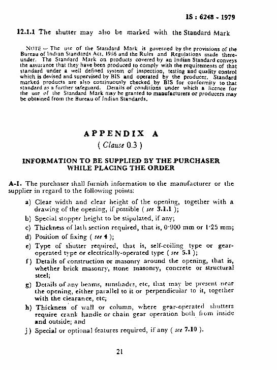
INFORMATION TO BE SUPPLIED BY THE PURCHASER WHlLE PLACING THE ORDER
A-l. The purchaser shall furnish information to the manufacturer or the
supplier in regard to the following points:
a) Clear width and clear height of the opening, together with a drawing of the opening, if possible ( JCC 3.1.1 );
b) Special stopper height to be stipulated, if any;
c) Thickness of lath section required, that is, 0.900 mm or 1.25 mm;
4 4
f-1
S>
h)
j)
Position of fixing ( see 4 );
Type of shutter Tequired, that is, self-coiling type or gear- operated t!rpe or electrically-operated typt ( see 5.1 ); Details of comtruction or masonry around the opening, that is, whether brick masonry, stone masonry, concrete or structural steel;
Dctnils of any beams, sunshndrs, ctc, that may bc prcscnt near the opening, either parallel to it or perpendicular to hit, tOgethCr
with the clearance, etc;
Thickness of wall or column, where gear-operated shutters require crank handle or chain gear operation both from inside and outside; and
Special or optionA.features required, if’any ( see 7.18 ).
21

BUREAU OF INDIAN STANDARDS
Headquarters: Manak Bhavan, 9 Bahadur Shah Zafar Marg, NEW DELHI 110002 Telephones: 323 0131,323 3375,323 9402 Fax : 91 11 3234062,91 11 3239399, 91 11 3239382
Telegrams : Manaksan$’ (Common to all Dffi
Central Laboratory: i , * 3 Telepho
Plot No. 20/9, Site IV, Sahibabad Industrial Area, Sahibabad 201010 !i 8-77 00 3;
Regional Offices:
Central : Manak Bhavan, 9 Bahadur Shah Zafar Marg, NEW DELHI 1 lb002 323 76 17
*Eastern : l/l 4 CIT Scheme VII M, V.I.P. Road, Maniktola, CALCUTTA 700054 337 86 62
Northern : SC0 335-336, Sector 34-A, CHANDIGARH ;60022 60 38 43
Southern : C.I.T. Campus, IV Cross Road, CHENNAI 600113 235 23 15
tWestern : Manakalaya, E9, Behind Marol Telephone Exchange, Andheri (East), MUMBAI 400093
832 9 : T
5 .,
Branch Offices::
‘Pushpak’, Nurmohamed Shaikh Marg, Khanpur, AHMEDABAD 380001
SPeenya Industrial~Area, 1 st Stage, Bangalore-Tumkur Road, BANGALORE 560058
550 13 48
839 49 55
Gangotri Complex, 5th Floor, Bhadbhada Road, T.T. Nagar, BHOPAL 462003 55 40 21
Plot No. 62-63, Unit VI, Ganga Nagar, BHUBANESHWAR 751001 40 36 27
Kalaikathir Buildings, 670 Avinashi Road, COIMBATORE 641037 21 01 41
Plot No. 43, Sector 16 A, Mathura Road, FARIDABAD 121001 8-28 88 01
Savitri Complex, 116 G.T. Road, GHAZIABAD 201001 8-71 19 96
53/5 Ward No.29, R.G. Barua Road, 5th By-lane, GUWAHATI 781003 541137
5-8-56C, L.N. Gupta Marg, Nampally Station Road, HYDERABAD 500001 201083
E-52, Chitaranjan Marg, C-Scheme, JAIPUR 302001 37 29 25
117/418 B, Sarvodaya Nagar, KANPUR 208005 21 68 76
Seth Bhawan, 2nd Floor, Behind Leela Cinema, Naval Kishore Road, 23 89 23 LUCKNOW 226001
NIT Building, Second Floor, Gokulpat Market, NAGPUR 440010 52 51 71
Patliputra Industrial Estate, PATNA 800013 ~26 23 05
Institution of Engineers (India) Building 1332 Shivaji Nagar, PUNE 411005 32 36 35
T.C. No. 14/l 421, University P. 0. Palayam, MIRUVANANTHAPURAM 695034 621 17
*Sales Office is at 5 Chowringhee Approach, P.O. Princep Street, CALCUTTA 700072
tSales Office is at Novelty Chambers, Grant Road, MUMBAI 400007
$Sales Office is at ‘F’ Block, Unity Building, Narashimaraja Square, BANGALORE 560002
271085
309 65 28
222 39 71
Printed at Dee Kay Printers, New Delhi, India