IS 4748 (2009): Steels - Micrographic Determination of The ...
42
Disclosure to Promote the Right To Information Whereas the Parliament of India has set out to provide a practical regime of right to information for citizens to secure access to information under the control of public authorities, in order to promote transparency and accountability in the working of every public authority, and whereas the attached publication of the Bureau of Indian Standards is of particular interest to the public, particularly disadvantaged communities and those engaged in the pursuit of education and knowledge, the attached public safety standard is made available to promote the timely dissemination of this information in an accurate manner to the public. इंटरनेट मानक “!ान $ एक न’ भारत का +नम-ण” Satyanarayan Gangaram Pitroda “Invent a New India Using Knowledge” “प0रा1 को छोड न’ 5 तरफ” Jawaharlal Nehru “Step Out From the Old to the New” “जान1 का अ+धकार, जी1 का अ+धकार” Mazdoor Kisan Shakti Sangathan “The Right to Information, The Right to Live” “!ान एक ऐसा खजाना > जो कभी च0राया नहB जा सकता ह ै” Bhartṛhari—Nītiśatakam “Knowledge is such a treasure which cannot be stolen” IS 4748 (2009): Steels - Micrographic Determination of The Apparent Grain Size [MTD 22: Metallography and Heat Treatment]
Transcript of IS 4748 (2009): Steels - Micrographic Determination of The ...

Disclosure to Promote the Right To Information
Whereas the Parliament of India has set out to provide a practical regime of right to information for citizens to secure access to information under the control of public authorities, in order to promote transparency and accountability in the working of every public authority, and whereas the attached publication of the Bureau of Indian Standards is of particular interest to the public, particularly disadvantaged communities and those engaged in the pursuit of education and knowledge, the attached public safety standard is made available to promote the timely dissemination of this information in an accurate manner to the public.
इंटरनेट मानक
“!ान $ एक न' भारत का +नम-ण”Satyanarayan Gangaram Pitroda
“Invent a New India Using Knowledge”
“प0रा1 को छोड न' 5 तरफ”Jawaharlal Nehru
“Step Out From the Old to the New”
“जान1 का अ+धकार, जी1 का अ+धकार”Mazdoor Kisan Shakti Sangathan
“The Right to Information, The Right to Live”
“!ान एक ऐसा खजाना > जो कभी च0राया नहB जा सकता है”Bhartṛhari—Nītiśatakam
“Knowledge is such a treasure which cannot be stolen”
“Invent a New India Using Knowledge”
है”ह”ह
IS 4748 (2009): Steels - Micrographic Determination of TheApparent Grain Size [MTD 22: Metallography and HeatTreatment]


IS 4748 : 2009 ISO 643 : 2003
Indian Standard
STEELS — MICROGRAPHIC DETERMINATION OF THE APPARENT GRAIN SIZE
( Second Revision )
ICS 77.040.99
©BIS 2009
B U R E A U OF I N D I A N S T A N D A R D S MANAK BHAVAN, 9 BAHADUR SHAH ZAFAR MARG NEW
DELH1110002
March 2009 Price Group 12

Metallography and Heat Treatment Sectional Committee, MTD 22
NATIONAL FOREWORD
This Indian Standard (Second Revision) which is identical to ISO 643 :2003 'Steels — Micrographic determination of the apparent grain size' issued by the International Organization for Standardization (ISO) was adopted by the Bureau of Indian Standards on the recommendation of the Metallography and Heat treatment Sectional Committee and approval of the Metallurgical Engineering Division Council.
The procedure for revealing out the grain size of ferritic and austenitic steels was covered in IS 2853:1964 'Method of determining austenitic grain size'. In 1968 the committee decided to issue a separate Indian Standard on Methods for estimating average grain size of metals and subsequently revised the standard in 1988 by incorporating method for estimating grain size of multiphase alloys which was earlier covered in IS 2853 :1964. This revision of the standard has been taken up to align it with ISO 643 :2003 by adoption, under dual numbering system.
The text of ISO Standard has been approved as suitable for publication as an Indian Standard without deviations. Certain conventions are, however, not identical to those used in Indian Standards. Attention is particularly drawn to the following:
a) Wherever the words 'International Standard' appear, referring to this standard, they should be read as 'Indian Standard'.
b) Comma (,) has been used as a decimal marker while in Indian Standards, the current practice is to use a point (.) as the decimal marker.
In this adopted standard, reference appears to the following International Standard for which Indian Standard also exists. The corresponding Indian Standard which is to be substituted in its place is listed below along with its degree of equivalence for the edition indicated:
International Standard Corresponding Indian Standard Degree of Equivalence
ISO 14250 : 2000 Steel — IS 15426 : 2004 Steel — Identical Metallographic characterization of Metallographic characterization of duplex grain size and distributions duplex grain size and distributions
The technical committee responsible for the preparation of this standard has reviewed the provisions of the following International Standards and has decided that they are acceptable for use in conjunction with this standard:
International Standard Title
ISO 3785 Steel — Designation of test piece
ASTM E 112 Standard test methods for determining average grain size
In reporting the results of a test or analysis, made in accordance with this standard, if the final value, observed or calculated, is to be rounded off, it shall be done in accordance with IS 2:1960 'Rules for rounding off numerical values (revised)'.

IS 4748 : 2009 ISO 643 : 2003
Indian Standard
STEELS — MICROGRAPHIC DETERMINATION OF THE APPARENT GRAIN SIZE
( Second Revision )
1 Scope
This International Standard specifies a micrographic method of determining apparent ferritic or austenitic grain size in steels. It describes the methods of revealing grain boundaries and of estimating the mean grain size of specimens with unimodal size distribution. Although grains are three-dimensional in shape, the metallographic sectioning plane can cut through a grain at any point from a grain corner, to the maximum diameter of the grain, thus producing a range of apparent grain sizes on the two-dimensional plane, even in a sample with a perfectly consistent grain size.
2 Normative references
The following referenced documents are indispensable for the application of this document. For dated references, only the edition cited applies. For undated references, the latest edition of the referenced document (including any amendments) applies.
ISO 3785, Steel—Designation of test piece axes
ISO 14250, Steel— Metallographic characterization of duplex grain size and distributions
ASTM E112, Standard Test Methods for Determining Average Grain Size
3 Terms and definitions
For the purposes of this document, the following terms and definitions apply.
3.1 grain closed polygonal shape with more or less curved sides, which can be revealed on a flat cross-section through the sample, polished and prepared for micrographic examination
A distinction is made between:
3.1.1 austenitic grain crystal with a face-centered cubic crystal structure which may, or may not, contain annealing twins
3.1.2 ferritic grain crystal with a body-centered cubic crystal structure which never contains annealing twins1) 1) Ferritic grain size is generally estimated for non-alloy steels with a carbon content of 0,25 % or less. If pearlite islands of identical dimensions to those of the ferrite grains are present, the islands are then counted as ferrite grains.
1

IS 4748 : 2009 ISO 643 : 2003
3.2 index positive, zero or possibly negative number G which is derived from the mean number m of grains counted in an area of 1 mm2 of the section of the specimen
NOTE By definition, G = 1 where m = 16; the other indices are obtained by the formula
m = 8 x 2G
3.3 intercept N number of grains intercepted by a test line, either straight or curved
See Figure 1.
NOTE Straight test lines will normally end within a grain. These end segments are counted as 1/2 an interception. N is the average of a number of counts of the number of grains intercepted by the test line applied randomly at various locations. N is divided by the true line length, LT, usually measured in millimetres, in order to obtain the number of grains intercepted per unit length, N L.
3.4 intersection P number of intersection points between grain boundaries and a test line, either straight or curved
See Figure 1.
NOTE P is the average of a number of counts of the number of grain boundaries intersected by the test line applied randomly at various locations. P is divided by the true line length, Z.T, usually measured in millimetres, in order to obtain the number of grain boundary intersections per unit length, P L
4 Symbols and abbreviated terms
The symbols used are given in Table 1.
5 Principle
The grain size is revealed by micrographic examination of a polished section of the specimen prepared by an appropriate method for the type of steel and for the information sought.
NOTE If the order or the International Standard defining the product does not stipulate the method of revealing the grain, the choice of this method is left to the manufacturer.
This average size is characterized either
a) by an index obtained
— usually by comparison with standard charts for the measurement of grain size;
— or by counting to determine the average number of grains per unit area;
b) or by the mean value of the intercepted segment.
2

Interception, N, counts for a straight line on a single-phase grain structure where the arrows point to 6 intercepts and two line segments ending within grain (2 x 1/2 = 1 N) and N=7
Intersection, P, counts for a straight test line placed over a single-phase grain structure where the arrows point to 7 intersection points and P =7
Figure 1 — Examples of intersection, P, and interception, N
3
IS 4748 : 2009 ISO 643 : 2003

IS 4748 : 2009 ISO 643 : 2003
4

IS 4748 : 2009 ISO 643 : 2003
6 Selection and preparation of the specimen
6.1 Test location If the order, or the International Standard defining the product, does not specify the number of specimens and the point at which they are to be taken from the product, these are left to the manufacturer, although it has been shown that precision of grain size determination increases the higher the number of specimens assessed. Therefore, it is recommended that two or more sections be assessed. Care shall be taken to ensure that the specimens are representative of the bulk of the product (i.e., avoid heavily deformed material such as that found at the extreme end of certain products or where shearing has been used to remove the specimen etc.). The specimens shall be polished in accordance with the usual methods. Unless otherwise stated by the product standard or by agreement with the customer, the polished face of the specimen shall be longitudinal, i.e., parallel to the principal axis of deformation in wrought products. Measurements of the grain size on a transverse plane will be biased if the grain shape is not equiaxial.
6.2 Revealing ferritic grain boundaries
The ferritic grains shall be revealed by etching with nital (ethanolic 2 % to 3 % nitric acid solution), or with an appropriate reagent.
6.3 Revealing austenitic and prior-austenitic grain boundaries
6.3.1 General In the case of steels having a single-phase or two-phase austenitic structure (delta ferrite grains in an austenitic matrix) at ambient temperature, the grain shall be revealed by an etching solution. For single phase austenitic stainless steels, the most commonly used chemical © tenants are glyceregia, Kalling's reagent (No. 2) and Marble's reagent. The best electrolytic etch for single or two-phase stainless steels is aqueous 60 % nitric acid at 1,4 V d.c. for 60 s to 120 s, as it reveals the grain boundaries but not the twin boundaries. Aqueous 10 % oxalic acid, 6 V d.c, up to 60 s, is commonly used but is less effective than electrolytic 60 % HN03. For other steels, one or other of the methods specified below shall be used depending on the information required.
— "Bechet-Beaujard" method by etching with aqueous saturated picric acid solution (see 6.3.2);
— "Kohn" method by controlled oxidation (see 6.3.3);
— "McQuaid-Ehn" method by carburization (see 6.3.4);
— grain boundary sensitization method (see 6.3.7);
— other methods specially agreed upon when ordering. NOTE The first three methods are for prior-austenitic grain boundaries while the others are for austenitic Mn or austenitic stainless, see Annex A. If comparative tests are carried out for the different methods, it is essential to use the same heat treatment conditions. Results may vary considerably from one method to the other.
5

IS 4748 : 2009 ISO 643 : 2003
6.3.2 "Bechet-Beaujard" method by etching with aqueous saturated picric acid solution
6.3.2.1 Field of application
This method reveals austenitic grains formed during heat treatment of the specimen. It is applicable to specimens which have a martensitic or bainitic structure. For this etch to work, there shall be at least 0,005 % P.
6.3.2.2 Preparation
The Bechet-Beaujard etchant is normally used on a heat-treated steel specimen. Normally, no subsequent heat treatment is necessary if the specimen has a martensitic or bainitic structure. If this is not the case, heat treatment is necessary.
If the conditions for treating the test piece are not provided for by the International Standard defining the product and there is no specification to the contrary, the following conditions shall be applied in the case of heat-treated structural carbon steels and low-alloy steels:
— 1,5 h at (850 ± 10) °C for steels whose carbon content is greater than 0,35 %;
— 1,5 h at (880 ± 10) °C for steels whose carbon content is less than or equal to 0,35 %.
After this treatment, the test piece shall be quenched into water or oil.
6.3.2.3 Polishing and etching
A flat specimen surface shall be polished for micrographic examination. It shall be etched for an adequate period of time by means of an aqueous solution saturated with picric acid together with at least 0,5 % sodium alkylsulfonate or another appropriate wetting agent.
NOTE The period of etching may vary from a few minutes to more than one hour. Heating of the solution to 60 °C may improve the etching action and reduce etching time.
Several successive etching and polishing operations are sometimes necessary to ensure a sufficient contrast between the grain boundaries and the general base of the specimen. In the case of through-hardened steel, tempering may be carried out before selecting the specimen.
WARNING: When heating solutions containing picric acid, caution shall be taken to avoid the solution boiling dry as picric acid can become explosive.
6.3.2.4 Result
The prior-austenite grain boundaries shall be immediately apparent on microscopic examination.
6.3.3 "Kohn" method by controlled oxidation
6.3.3.1 Field of application
This method shows up the austenitic grain pattern formed by preferential oxidation of the boundaries during austenization at the temperature of a given heat treatment.
6.3.3.2 Preparation
One surface of the specimen shall be polished. The rest of its surface shall not show any traces of oxide. The specimen shall be placed in a laboratory furnace in which either a vacuum of 1 Pa is attained or an inert gas is circulated (e.g. purified argon). Heat treat the specimen in accordance with the austenitizing procedure specified by the customer, or as defined by the International Standard governing the product.
6

IS 4748 : 2009 ISO 643 : 2003
At the end of this specified heating period, air shall be introduced into the furnace for a period of 10 s to 15 s.
The specimen shall then be water-quenched. The specimen can usually be directly examined using a microscope.
NOTE 1 The oxidation method can be done without the inert atmosphere.
NOTE 2 The oxide adhering to the previously polished surface should be removed by light polishing with a fine abrasive, taking care that the oxide network which has formed on the grain boundaries is retained; then the polishing should be completed by the usual methods. The specimen should then be etched using Viieita's reagent:
— picric acid 1 g
— hydrochloric acid 5 ml
— ethanol 100 ml
6.3.3.3 Result
The preferential oxidation of the boundaries shows up the pattern of austenitic grains.
If the preparation is effected correctly, no oxide globules should appear at the grain boundaries.
In certain cases, it may be necessary to use oblique illumination, or DIC (Differential Interference Contrast) methods, to show up the boundaries in better relief.
6.3.4 "McQuaid-Ehn" method by carburization at 925 °C
6.3.4.1 Field of application
This is a method specifically for carburizing steels and shows up austenitic grain boundaries formed during carburization of these steels. It is not usually suitable for revealing grains actually formed during other heat treatments.
NOTE The "mock carburizing" procedure may also be used. The specimen is subjected to the same thermal treatment but without a carbon-rich atmosphere. It is then heat-treated as the product would be treated. The Bechet-Beaujard reagent is used to reveal the grain boundaries, see 6.3.2.
6.3.4.2 Preparation
The specimens shall be free from any trace of decarburization or of surface oxidation. Any prior treatment, either cold, hot, mechanical, etc., may have an effect on the shape of the grain obtained; the product specification shall state the treatments to be carried out before determination in cases where it is advisable to take into account these considerations.
After carburizing, the specimen must be cooled at a rate slow enough to precipitate cementite at the grain boundaries in the hypereutectoid surface region of the carburized specimen.
Carburization shall be achieved by maintaining the specimen at (925 ± 10) °C for 6 h. This is generally done by keeping the carburizing chamber at (925 ± 10) ºC for 8 h, including a pre-heating period. In most cases, a carburized layer of approximately 1 mm is obtained. After carburizing, cool the specimen at a rate slow enough to ensure that the cementite is precipitated at the grain boundaries of the hypereutectoid zone of the carburized layer. Fresh carburizing compound shall be used each time.
7

IS 4748 : 2009 ISO 643 : 2003
6.3.4.3 Specimen preparation
The carburized specimen shall be sectioned normally to its surface. One of the sections shall be prepared for micrographic examination and etched using either a) or b).
a) "Le Chatelier and Igewski" reagent (alkaline sodium picrate);
— picric acid 2g
— sodium hydroxide 25 g
— water 100 ml
Use this reagent by immersion at 100 X, for at least 1 min, or at room temperature by means of electrolytic etching 6 V d.c. for 60 s.
b) Nital:
— nitric acid 2 ml to 5 ml
— ethanol to make up to 100 ml
Other reagents may be used as long as the same results are obtained.
6.3.4.4 Result
The prior-austenite grain boundaries in the hypereutectoid carburized surface layer will be delineated by proeutectoid cementite.
6.3.5 Proeutectoid ferrite method
NOTE Guidelines for the use of this method depending on the microstructure of the steel product are given in Annex A.
6.3.5.1 Principle
This method is suitable for carbon steei with about 0,25 % to 0,6 % carbon and for low-alloy steels such as manganese-molybdenum, 1 % chromium, 1 % chromium-molybdenum and 1,5 % nickel-chromium. The prior-austenitic grain boundaries are revealed as a network of proeutectoid ferrite.
6.3.5.2 Preparation
Use the austenizing conditions as given in the product standard. In the case of carbon or other low hardenability steel, either air cool, furnace coot or partially transform isothermally the test pieces in such a manner as to outline the austenitic grain boundaries with ferrite.
In the case of alloy steels, after austenitizing, partially transform isothermally the test pieces at an appropriate temperature within the range 650 °C to 720 "C and then water quench.
NOTE 1 The time required for transformation will vary according to the steel, but usually sufficient ferrite has precipitated in 1 min to 5 min, although longer times, up to about 20 min, can sometimes be required.
NOTE 2 For alloy steels, a test piece 12 mm x 6 mm x 3 mm is suitable to obtain uniform transformation during the isothermal treatment
6.3.5.3 Polishing and etching
Section, polish and etch the test pieces for micrographic examination. Etch the test pieces with a suitable etchant such as hydrochloric acid and picric acid (Vilellas' reagent).
8

IS 4748 : 2009 ISO 643 : 2003
6.3.6 Bainite or gradient-quench method
NOTE Guidelines for the use of this method depending on the microstructure of the steel product are given in Annex A.
6.3.6.1 Principle
This method is suitable for steels of approximately eutectoid composition, i.e., having a carbon content of 0,7 % by mass or higher. The boundaries of the prior-austenitic grains are revealed by a network of fine pearlite or bainite outlining the martensite grains.
6.3.6.2 Preparation
Heat the test piece to a temperature not more than 30 °C above Ac3 (i.e., the temperature at which ferrite completes its transformation to austenite during heating) to ensure full austenitization.
Coo! the specimen at a controlled rate to produce a partially hardened structure of fine pearlite or bainite outlining the martensite grains.
This structure may be produced in one of the following ways:
a) by completely quenching in water or oil, as appropriate, a bar of cross-sectional dimensions such that it will fully harden at the surface but only partially harden in the centre;
b) by gradient quenching a length of bar, 12 mm to 25 mm diameter or square, by immersing it in water for a part of the length only.
Then polish and etch.
6.3.7 Sensitization of austenitic stainless and manganese steels
The grain boundaries may be developed through precipitation of carbides by heating within the sensitizing temperature range, 482 °C to 704 "C (900 °F to 1 300 °F). Any suitable carbide-revealing etchant can be used.
NOTE This method should not be used in case of very low carbon contents in austenitic grades.
6.3.8 Other methods for revealing prior-austenitic grain boundaries
For certain steels, after simple heat treatment (annealing or normalizing, quenching and tempering, etc.), the pattern of the austenitic grains may appear in the following forms under micrographic examination: a network of proeutectoid ferrite surrounding pearlite grains, a network of very fine pearlite surrounding martensite grains, etc. The austenitic grain may also be revealed by thermal etching under vacuum (not necessarily followed by oxidation). The product specification shall mention these simplified methods2) in these cases. 2) Amongst these methods are the following;
— precipitation on the grain boundaries during cooling;
— gradient quenching method, etc.
9

IS 4748 : 2009 ISO 643 : 2003
7 Characterization of grain size
7.1 Characterization by an index
7.1.1 Formulae
The index is defined in 3.2 by the formula
M = 8 X 2G
This formula may be stated as Or
(1)
(2a)
(2b)
7.1.2 Assessment by comparison with standard grain size charts
The image examined on the screen (or on a photomicrograph) is compared with a series of standard charts3* or overlays (eye-piece graticules designed for grain size measurement can be used providing these are traceable to National or International standards). The standard charts at a magnification of x 100 are numbered from 00 to 10 so that their number is equal to the index G.
The standard chart with the grain size closest to that of the examined fields of the specimen can then be determined. A minimum of three randomly-selected fields shall be assessed on each specimen.
Where the magnification g of the image on the screen or photomicrograph is not x 100, the index G shall be equal to the number hi of the closest standard chart, modified as a function of the ratio of the magnifications:
Table 2 gives the relationship between the indices for the usual magnifications.
Table 2 — Relationship between indices for the usual magnifications
(3)
Magnification of the image Index of metal grain for an image identified on a standard chart No.
25 -3 -2 -1 0 1 2 3 4
50 -1 0 1 2 3 4 5 6
100 1 2 3 4 5 6 7 8
200 3 4 5 6 7 8 9 10
400 5 6 7 8 9 10 11 12
. 500 5,6 6,6 7,6 8,6 9,6 10,6 11,6 12,6
800 7 8 9 10 11 12 13 14
3) These standard charts are defined in ASTM E112 {(plates IA and IB) (Annex B)]. The standard charts selected should be adhered to throughout the whole of the examination.
10

IS 4748 : 2009 ISO 643 : 2003
7.1.3 Planimetric method
The evaluation method is defined in Annex C.
7.1.4 Estimation of the index
Whether the estimate is carried out by comparison or by count, the accuracy obtained is rarely greater than a half-unit. The index shown shall be rounded to a whole number.
7.2 Characterization by the intercept method
Count the number of grains intercepted, N, or the number of grain boundary intersections, P, with a test line of known length on a projection screen, on a reticle, on a television-type monitor or on a photomicrograph of a representative of the bulk of the specimen at a known magnification, g.
The measuring line may be straight or circular. The measuring grid in Figure 2 shows the types of recommended measuring line.
The grid shall be applied only once to the field examined. It is applied at random to an adequate number of fields to have a valid count.
The dimensions in millimetres of the three circles shall be:
Diameter Circumference
79,58 250,0
53,05 166,7
26,53 83,3
Total 500,0
7.2.1 Linear intercept segment method
7.2.1.1 Figure 2 shows a test pattern that can be used to measure grain size by the intercept method. The three concentric circles have a total line length of 500 mm. A circular test grid averages out variations in the shape of equiaxed grains and avoids the problem of lines ending within grains. Figure 2 also has four straight lines; two oriented diagonally, one vertically and one horizontally. Each diagonal line has a length of 150 mm while the horizontal and vertical lines are each 100 mm long. The straight lines will also average out variations in the shape of equiaxed grains. Alternatively, if the degree of grain elongation is of interest, grain counts can be made using only the vertical and horizontal lines (separately) when they are aligned so that the horizontal line is parallel to the deformation axis (and the vertical line is then perpendicular to the deformation axis) on a longitudinally-oriented polished plane [see 7.2.3, c)].
The magnification shall be selected so that at least 50 intercepts are obtained in any one field. At least five randomly selected fields shall be assessed with a total number of intercepts of at least 250.
NOTE If the grain size of the specimen requires the magnification to be changed in order to achieve the required number of intercepts, the length of the measuring lines can also be varied providing that the orientation of the measuring lines is arranged to take account of the effects of anisotropy.
The following rules apply to interception and intersection counts of single-phase grain structures using straight test lines.
11

IS 4748 : 2009 ISO 643 : 2003
Figure 2 — Recommended measurement grid for the intercept segment method
7.2.1.2 When the number of intercepted grains, N, is counted:
— if a test line goes through a grain, N is 1;
— if a test line terminates within a grain, N is 0,5;
— if a test line is tangential to a grain boundary, N is 0,5.
7.2.1.3 When the number of grain boundary intersections, P, is counted:
— if a test line passes through a grain boundary, P is 1;
— if a test line is tangential to a grain boundary, P is 1;
— if a test line intersects a triple point, P is 1,5
NOTE The "Snyder-Graff' method, described in Annex C, represents a linear intercept method for tool steel (high-speed steels).
7.2.2 Circular intercept segment method
The pattern of circles shown in Figure 2 is recommended.
The measuring line consists either of a set of three concentric circles as shown in Figure 2 or of one single circle.
12

IS 4748 : 2009 ISO 643 : 2003
The total length of the three circles of the recommended grid shown in Figure 2 is 500 mm. The magnification or diameter of the circle shall be selected so that there are 40 to 50 intercepts when the measurement grid is superposed on the field to be examined.
In the case of a single circle, the largest circle with a circumference of 250 mm is used. In this case, the magnification to be used shall enable at least 25 intercepts to be counted.
The circular intercepted segment method tends to give slightly high intercepted segment values and thus a slightly low number of intersections. In order to compensate for this, the intersections caused by a triple point shall be counted as two intersections instead of 1,5 as is the case with the linear intercepted segment method.
7.2.3 Assessment of results
Counts of the number of intercepts, N, or intersections, P, are made on a number of fields selected at random. The mean value of the number of intercepts, N, or intersections, P, is calculated.
If LT is the true length of the test line then
For the case of non-equiaxed grain structures, counts can be made of the number of interceptions, N, or intersections, P, of the grains or grain boundaries, with straight test lines oriented parallel to the three principal directions. These three directions can be found on any two of the three principal test planes (longitudinal, transverse and planar).
The mean number of intercepts per millimetre, N L, or the mean number of intersections per millimetre, P L, is determined from the cube root of the product of the three measurements:
where the bars above the quantities indicate that they are the means (averages) of a number of measurements and x, y, and z indicate the principal directions (longitudinal, transverse and planar).
a) Grains of different size indices: In certain cases, the specimen examined may include grains belonging to two or more different systems of size indices. This can be recognized by the presence of several grains of greatly differing dimensions from those of the whole, e.g., see ISO 14250.
b) Twin grains: Unless otherwise specified, these are counted as a single grain, that is, twin boundaries are ignored (see Figure 3).
c) Non-equiaxed grains: The grain shape can be expressed by dividing the mean lineal intercept length in the deformation direction by the mean lineal intercept length perpendicular to the deformation direction using a longitudinally oriented test specimen. This is referred to as the grain elongation ratio, or the anisotropy index.
d) Modern methods of grain size measurement: Such as ultrasonic methods, automatic image analysis, etc., can be used to measure grain size of applicable materials providing that the accuracy of the methods has previously been proven by an extensive cross correlation.
13

IS 4748 : 2009 ISO 643 : 2003
Figure 3 — Evaluation of number of grains (twin grains)
8 Test report
The test report shall contain the following information:
a) grade of the steel examined;
b) type of grain determined;
c) method used, operating conditions, method of evaluation (i.e., manual or automatic image analysis);
d) grain size index or the value of the mean segment.
14

IS 4748 : 2009 ISO 643 : 2003
Annex A
(informative)
Summary of methods for revealing ferritic, austenitic or prior-austenitic
grain boundaries in steels
Method Applicable steels
The "Bechet-Beaujard" etch method (see 6.3.2) Steels with martensitic. tempered martensitic or bainitic structures that contain ≥ 0,005 % phosphorus
The "Kohn" oxidation method (see 6.3.3) Carbon and low-alloy steels
The "McQuaid-Ehn" carburizing method (see 6.3.4)
The mock carburizing method (see 6.3.4)
Carburizing steels
The proeutectoid ferrite delineation method (see 6.3.5) Coarse-grained carbon steels with between 0,26 % and 0,6 % carbon; also low-alloy steels such as Mn-Mo, 1 % Cr, 1 % Cr-Mo and 1,5 % Cr-Ni
The bainite or gradient quench method (see 6.3.6) Coarse-grained steels of approximately eutectoid carbon content, i.e., 0,7 % to 0,8 % carbon
The grain boundary sensitization method (see 6.3.7) Unstabilized austenitic or duplex stainless steels with a carbon content > 0,025 % a
The quenching and tempering method (see 6.3.8) Carbon steels
Direct etching using a suitable reagent (see 6.2) All single-phase steels
a Austenitic Mn steels will precipitate -a fine carbide aggregate at the grain boundaries when aged between 550 °C and 600 °C.
15

IS 4748 : 2009 ISO 643 : 2003
Annex B
(normative)
Determination of grain size — Standard charts taken from ASTM E1124)
Plate 1A — Untwinned grains (flat etch) x 100
4) The charts are reproduced, with permission, from ASTM E112. For a comparison chart showing the grain size, please contact ASTM, 100 Barr Harbor Drive, Philadelphia, PA 19428-3914, USA (refer to adjunct No. ADJ 12-501120-10).
16

Plate 1A (continued) — Untwinned grains (flat etch) x 100
IS 4748 : 2009 ISO 643 : 2003
17

IS 4748 : 2009 ISO 643 : 2003
Plate 1A (continued) — Untwinned grains (flat etch) x 100
18

Plate 1A (continued) — Untwinned grains (flat etch) x 100
IS 4748 : 2009 ISO 643 : 2003
19

20
IS 4748 : 2009 ISO 643 : 2003
Plate 1A (continued) — Untwinned grains (flat etch) x 100

Plate 1A (continued) — Untwinned grains (flat etch) x 100
IS 4748 : 2009 ISO 643 : 2003
21

IS 4748 : 2009 ISO 643 :2003
Plate 1A (continued) — Untwinned grains (flat etch) x 100
22

Plate 1B — Untwinned grains (flat etch) x 100
3.0
3.5
IS 4748 : 2009 ISO 643 : 2003
23
IS 4748 : 2009 ISO 643 : 2003
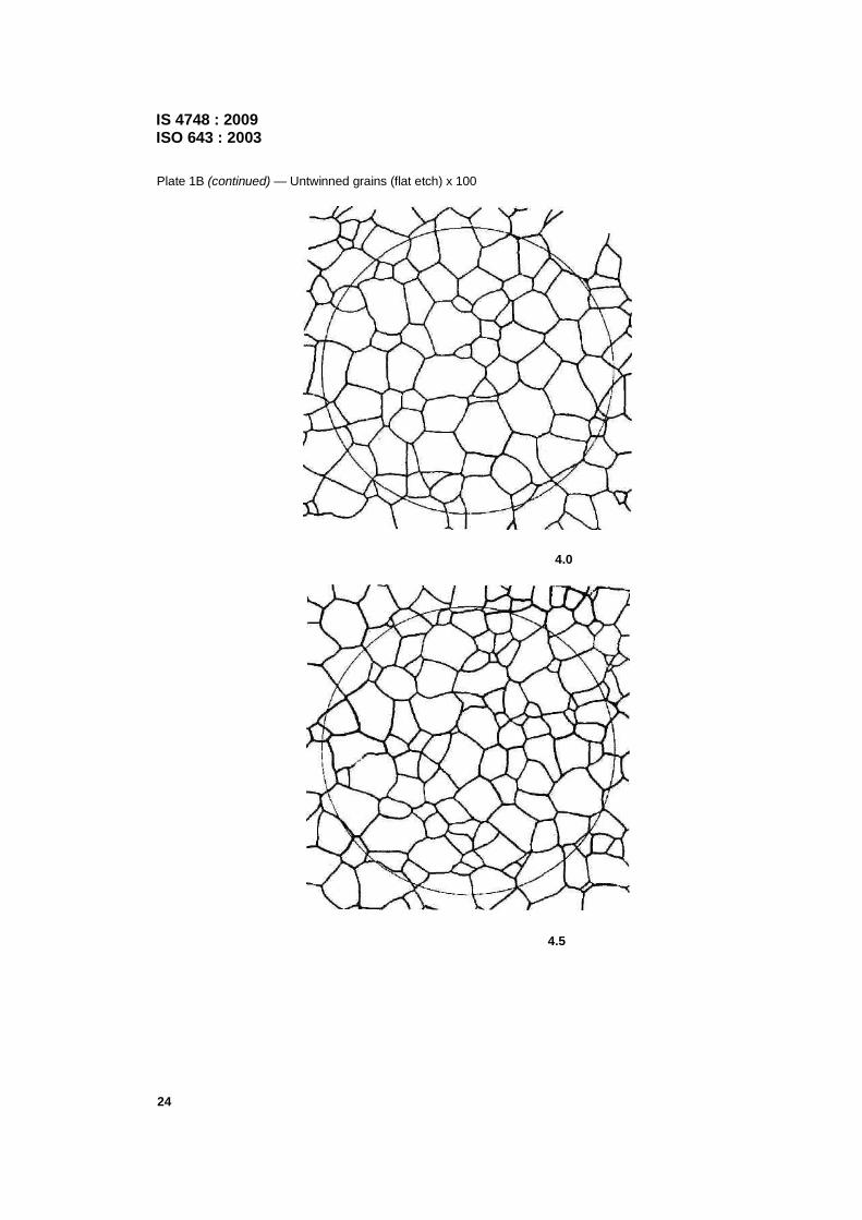
Plate 1B (continued) — Untwinned grains (flat etch) x 100
24
4.0
4.5

Plate 1B (continued) —~ Untwinned grains (flat etch) x 100
5.0
5.5
IS 4748 : 2009 ISO 643 :2003
25

IS 4748 : 2009 ISO 643 : 2003
Plate 1B {continued) — Untwinned grains (flat etch) x 100
26
6.0
6.5

Plate 1B {continued) — Untwinned grains (flat etch) x 100
7.0
7.5
IS 4748 : 2009 ISO 643 : 2003
27

IS 4748 : 2009 ISO 643 : 2003
Plate 1B {continued) — Untwinned grains (flat etch) x 100
28
8.0
8.5

IS 4748 : 2009 ISO 643 : 2003
Plate 1B (continued) — Untwinned grains (flat etch) x 100
9.0
9.5
29

IS 4748 : 2009 ISO 643 : 2003
Plate 18.{continued) — Untwinned grains (fiat etch) x 100
30
10.0

IS 4748 : 2009 ISO 643 : 2003
Annex C
(normative)
Evaluation method
C.1 Principle of the planimetric method
Historically, a circle measuring 79,8 mm in diameter was drawn on or superimposed over a micrograph or a live image on a ground glass projection screen. The magnification was adjusted so that the circular area contained at least 50 grains. This recommendation was made to minimize the counting error associated with a circular test pattern.
Figure C.1 — Evaluation of number of grains in an area enclosed by a circle Two counts are made: n1 is the number of grains completely within the test circle while n2 number of grains intersected by the test circle.
The total number of equivalent grains is
(C.1)
31

IS 4748 : 2009 ISO 643 : 2003
The number of grains per mm2, m, on the specimen surface is computed from
m= 2n100 (C.2)
or, in the case of any magnification, g
m = (g2/5 000)ng (C.3)
where 5 000 is the test circle area in mm2.
This approach assumes that, on average, half of the grains intersected by the test circle are within the circle while half are outside the circle. This assumption is valid for a straight line through a grain structure, but not for a curved line. The bias created by this assumption increases as the number of grains inside the test circle decreases. If the number of grains within the test circle is at least 50, the bias is about 2 %.
A simple way to avoid this bias, irrespective of the number of grains within the test figure, is to use a square or rectangle. However, the counting procedure must be modified slightly. First, it is assumed that the grains intersecting each of the four comers are, on average, one fourth within the figure and three-fourths outside. These four corner grains together equal one grain within the test box.
Ignoring the four corner grains, a count is made of n1 the grains completely within the box; and, n2 the grains intersected by the four sides of the box (see Figure C.1). Equation C.1 now becomes:
n100 = (n1 + 0.5n2 + 1) (C.4)
32
Figure C.2 — Evaluation of the number of intercepts or intersections

IS 4748 : 2009 ISO 643 : 2003
The number of grains per square millimeter, m, on the surface of the specimen is
(C.5)
where AF is the apparent area of the test figure used for grain counting in mm2.
The mean grain area in square millimetres is calculated from
(C.6)
It has been common practice to calculate a mean grain diameter from the following equation, but use of this approach is not recommended as it implies that grains are square in cross section, which they are not.
(C.7)
A nominal value of m corresponds to each value of G. The values of m calculated by formula (C.2) or (C.3) within the limits given in Table C.1 are given to a whole value of G.
C.2 "Snyder-Graff method5)
C.2.1 Field of application
This method is used for determining the prior-austenitic grain size of hardened and tempered high-speed steels by means of the linear intercept method.
C.2.2 Preparation
The specimen, taken from the product that is usually in the hardened and tempered condition, shall not receive any supplementary heat treatment.
After being polished, the specimen shall be etched using nital containing up to 10 % by volume of nitric acid in ethanol. Etch the specimen long enough to clearly reveal the prior-austenitic grain boundaries. Several successive polish/etch cycles may be necessary. The surface of the specimen is more or less coloured depending on the type of heat treatment undergone by the product.
C.2.3 Measuring
Under a magnification of x 1 000, the number of grains intercepted by a measuring line 125 mm long shall be counted. Five counts shall be carried out in different directions in fields selected at random.
C.2.4 Result
Unless specified to the contrary, the arithmetic mean of the number of grains intercepted in five counts characterizes the grain size. The mean intercepted segment may be determined from this value. 5) Snyder, R.W. and Graff, H.F., Study of grain size in hardened high-speed steel, Metal Progress (1938), April, pp 377-80.
33

IS 4748 : 2009 ISO 643 : 2003
Table C.1 — Evaluation of number of grains as a function of various parameters
Grain size indices
G
Number of grains, per square Millimeter m Limit values Normal Value from (excl.) to (incl.)
Mean diameter of grain
d
mm
Mean area of grain
a
mm2
Mean intersected
segment l
mm
Mean number of intercepts
on the measuring
line, per millimetre
-7 0,062 5 0,046 0,092 4 16 3,577 0,279
-6 0,125 0,092 0,185 2,828 8 2,529 0,395
-5 0,25 0,185 0,37 2 4 1,788 0,559
-4 0,50 0,37 0,75 1,414 2 1,265 0,790
-3 1 0,75 1.5 1 1 0,894 1,118
-2 2 1,5 3 0,707 0,5 0,632 1,582
-1 (00) 4 3 6 0,500 0,25 0,447 2,237
0 8 6 12 0,354 0,125 0,320 3.125
1 16 12 24 0,250 0.062 5 0,226 4,42
2 32 24 48 0,177 0.031 2 0,160 6,25
3 64 48 96 0.125 0,015 6 0,113 8,84
4 128 96 192 0,088 4 0,007 81 0,080 12,5
5 256 192 384 0,062 5 0,003 90 0,056 6 17,7
6 512 384 768 0,044 2 0,001 95 0,040 0 25,0
7 1 024 768 1 536 0,031 2 0,000 98 0,028 3 35,4
8 2 048 1 536 3 072 0.022 1 0,000 49 0,020 0 50,0
9 4 096 3 072 6144 0.015 6 0.000 244 0,014 1 70,7
10 8 192 6 144 . 12 288 0,011 0 0,000122 0,010 0 100
11 16 384 12 288 24 576 0,007 8 0,000 061 0,007 07 141
12 32 768 24 576 49 152 0,005 5 0,000 030 0,005 00 200
13 65 536 49 152 98 304 0,003 9 0,000 015 0,003 54 283
14 131 072 98 304 196 608 0,002 8 0,000 007 5 0,002 50 400
15 262 144 196 608 393 216 0,002 0 0,000 003 7 0,001 70 588
16 524 288 393 216 786 432 0,001 4 0,000 001 9 0,001 20 833
17 1 048 576 786 432 1 572 864 0,001 0 0,000 000 95 0,000 87 1 149
NOTE This table gives the values between the different parameters for equiaxed grains.
34

IS 4748 : 2009
ISO 643 : 2003
C.3 An alternative system of grain size definition
C.3.1 General
In addition to the grain size definition system described in this International Standard, there is one other system, as used in the U.S.A.
This system (see ASTM E112) defines the grain size by an index G, known as the ASTM grain size, as shown in C.3.2 and C.3.3.
C.3.2 Mean intersected segment method
Index G (ASTM) = 0, corresponds to a mean intersected segment of 32,0 mm measured at a magnification of x 100.
The equation giving the other indices as a function of
— the mean intersected segment is
G (ASTM) = - 3,287 7 - 6,643 9 log l (C.8)
— the mean number of intercepts per unit length (mm) is
G (ASTM) = - 3,287 7 + 6,643 9 log NL (C.9)
C.3.3 Count method
By definition, index G (ASTM) = 1 corresponds to 15,5 grains per unit area (square miilimetre).
The equation giving the other indices as a function of the number of grain per unit area (square millimetre) is
G (ASTM) = - 2,954 2 + 3,321 9 log m (C.10)
C.3.4 Numerical ratios between the various grain size indices in the case of regular structures
The ASTM index gives a grain size slightly larger than the one defined by this international Standard, but the difference does not reach one twentieth of an index unit. This is negligible, as the estimation of grain size cannot generally be accurate to more than one half a unit under even the most favourable conditions.
Equations (2a) and (2b) given in 7.1 may be written as
G = -3+ 3,321 9 log m (C.11)
Comparing this-formula with formula (C.10) shows that
G (ASTM) - G = 0,045 8
35
MGIPF—142 Deptt.of BIS/2009—1-8-2009—300 Books.


Bureau of Indian Standards
BIS is a statutory institution established under the Bureau of Indian Standards Act, 1986 to promote harmonious development of the activities of standardization, marking and quality certification of goods and attending to connected matters in the country.
Copyright
BIS has the copyright of all its publications. No part of the these publications may be reproduced in any form without the prior, permission in writing of BIS. This does not preclude the free use, in the course of implementing the standard, of necessary details, such as symbols and sizes, type or grade designations. Enquiries relating to copyright be addressed to4he Director (Publications), BIS.
Review of Indian Standards
Amendments are issued to standards as the need arises on the basis of comments. Standards are also reviewed periodically; a standard alongwith amendments is reaffirmed when such review indicates that no changes are needed; if the review indicates that changes are needed, it is taken up for revision. Users of Indian Standards should ascertain that they are in possession of the latest amendments or edition by referring to the latest issue of 'BIS Catalogue' and 'Standards: Monthly Additions'.
This Indian Standard has been developed from Doc: No. MTD 22 (4751).
Amendments Issued Since Publication
Amend No. Date of Issue Text Affected
BUREAU OF INDIAN STANDARDS
Headquarters :
Manak Bhavan, 9 Bahadur Shah Zafar Marg, New Delhi 110 002 Telephones : 2323 0131, 2323 3375, 2323 9402 Website : www.bis.org.in
Regional Offices :
Central Manak Bhavan, 9 Bahadur Shah Zafar Marg NEW DELHI 110 002
Eastern 1/14 C.l.T. Scheme VII M, V.I.R Road, Kankurgachi KOLKATA 700 054
Northern SCO 335-336, Sector 34-A, CHANDIGARH 160 022
Southern C.l.T. Campus, IV Cross Road, CHENNAI 600 113
Manakalaya, E9 Ml DC, Marol, Andheri (East) MUMBAI 400 093
Telephones
2323 7617 2323 3841
2337 8499, 2337 8561 2337 8626, 2337 9120
260 3843 260 9285
2254 1216, 2254 1442 2254 2519, 2254 2315
2832 9295, 2832 7858 2832 7891, 2832 7892
Branches : AHMEDABAD. BANGALORE. BHOPAL BHUBANESHWAR. COIMBATORE. FARIDABAD. GHAZIABAD. GUWAHATI. HYDERABAD. JAIPUR. KANPUR. LUCKNOW. NAGPUR. PARWANOO. PATNA. PUNE. RAJKOT.THIRUVANANTHAPURAM. VISAKHAPATNAM.
Printed by the Manager, Govt, of India Press, Faridabad
Western