
IS 4682-1 (1994): Code of practice for lining of vessels ... · CODE OF PRACTICE FOR LINING OF...
30
Disclosure to Promote the Right To Information Whereas the Parliament of India has set out to provide a practical regime of right to information for citizens to secure access to information under the control of public authorities, in order to promote transparency and accountability in the working of every public authority, and whereas the attached publication of the Bureau of Indian Standards is of particular interest to the public, particularly disadvantaged communities and those engaged in the pursuit of education and knowledge, the attached public safety standard is made available to promote the timely dissemination of this information in an accurate manner to the public. इंटरनेट मानक “!ान $ एक न’ भारत का +नम-ण” Satyanarayan Gangaram Pitroda “Invent a New India Using Knowledge” “प0रा1 को छोड न’ 5 तरफ” Jawaharlal Nehru “Step Out From the Old to the New” “जान1 का अ+धकार, जी1 का अ+धकार” Mazdoor Kisan Shakti Sangathan “The Right to Information, The Right to Live” “!ान एक ऐसा खजाना > जो कभी च0राया नहB जा सकता ह ै” Bhartṛhari—Nītiśatakam “Knowledge is such a treasure which cannot be stolen” IS 4682-1 (1994): Code of practice for lining of vessels and equipment for chemical processes, Part 1: Rubber lining [MED 17: Mechanical Engineering]
Transcript of IS 4682-1 (1994): Code of practice for lining of vessels ... · CODE OF PRACTICE FOR LINING OF...

Disclosure to Promote the Right To Information
Whereas the Parliament of India has set out to provide a practical regime of right to information for citizens to secure access to information under the control of public authorities, in order to promote transparency and accountability in the working of every public authority, and whereas the attached publication of the Bureau of Indian Standards is of particular interest to the public, particularly disadvantaged communities and those engaged in the pursuit of education and knowledge, the attached public safety standard is made available to promote the timely dissemination of this information in an accurate manner to the public.
इंटरनेट मानक
“!ान $ एक न' भारत का +नम-ण”Satyanarayan Gangaram Pitroda
“Invent a New India Using Knowledge”
“प0रा1 को छोड न' 5 तरफ”Jawaharlal Nehru
“Step Out From the Old to the New”
“जान1 का अ+धकार, जी1 का अ+धकार”Mazdoor Kisan Shakti Sangathan
“The Right to Information, The Right to Live”
“!ान एक ऐसा खजाना > जो कभी च0राया नहB जा सकता है”Bhartṛhari—Nītiśatakam
“Knowledge is such a treasure which cannot be stolen”
“Invent a New India Using Knowledge”
है”ह”ह
IS 4682-1 (1994): Code of practice for lining of vesselsand equipment for chemical processes, Part 1: Rubber lining[MED 17: Mechanical Engineering]

IS 4682 ( Part 1 ) : 1994 (Reaffirmed 2008)
Indian Standard CODE OF PRACTICE FOR LINING OF
VESSELS AND EQUIPMENT FOR CHEMICAL PROCESSES
PART 1 RUBBER LINING
(First Revision) Second Reprint DECEMBER 2001
UDC 66.023.3 : 621.642 : 678.4 : 006.76
© BIS 1994 B U R E A U O F I N D I A N S T A N D A R D S MANAK BHAVAN, 9 BAHADUR SHAH ZAFAR MARG
NEW DELHI 110002
December 1994 Price Group 9
Chemical Engineering Plants and Related Equipment Sectional Committee, HMD 17
CONTENTS
SECTION 1 GENERAL
1 SCOPE
2 REFERENCES 3 TERMINOLOGY
4 EXCHANGE OF INFORMATION 5 COMPLIANCE
..
...
. . ...
...
...
...
... ...
...
...
...
...
...
...
... ... ... ... ...
PAGE 1 1 1 1 2
SECTION 2 DESIGN, FABRICATION AND SURFACE FINISH OF EQUIPMENT TO BE LINED
6 GENERAL ... 7 DESIGN OF METAL EQUIPMENT TO BE LINED 8 FABRICATION OF METAL EQUIPMENT TO BE LINED
9 DESIGN OF CONCRETE EQUIPMENT TO BE LINED
...
...
...
... 10 CONSTRUCTION OF CONCRETE EQUIPMENT TO BE LINED
...
...
...
...
...
... ...
...
...
...
2 2 3 6 9
SECTION 3 SELECTION AND QUALITY OF LININGS 11 SELECTION OF LINING 12 QUALITY OF LINING
...
... ... ...
...
... ... ...
9 10
SECTION 4 METHOD OF LINING 13 SURFACE PREPARATION ... 14 ADHESION SYSTEM AND APPLICATION 15 PRODUCTION OF LINING MATERIAL ... 16 APPLICATION OF THE SHEET TO THE SUBSTRATE 17 VULCANIZATION ...
...
...
...
... ...
...
...
...
...
...
...
...
...
...
...
10 11 11 11 13
SECTION 5 INSPECTION AND TESTING 18 RESPONSIBILITY FOR INSPECTION AND TESTING 19 INSPECTION
20 TESTING
20.1 Hardness Tests
...
...
..
...
...
...
.. 20.2 Continuity of Lining ( High Frequency Spark Test ) 20.3 Bond Strength Tests 20.4 Lining Thickness
...
... 20.5 Hydraulic Testing of Lined Equipment 20.6 Vacuum Testing of Lined Equipment
...
...
...
... 21 RECTIFICATION OF FAULTS IN FULLY CURED LININGS
...
...
...
...
...
...
...
...
...
...
...
...
...
...
...
...
...
...
...
...
14 14 16 16 16 16 17 17 17 17
SECTION 6 STORAGE, HANDLING, TRANSPORTATION, INSTALLATION AND MAINTENANCE
22 GENERAL
23 MAINTENANCE
...
... ANNEX A LIST OF REFERRED INDIAN STANDARDS ANNEX B LINING OF USED EQUIPMENT ... ANNEX C CHARACTERISTICS OF LINING MATERIALS ANNEX D EFFECT or MATERIALS ON WATER QUALITY
ANNEX E VULCANIZATION ... ANNEX F METHOD OF TEST FOR CONTINUITY TESTING
...
...
... ... ... ... ... ...
...
...
... ...
...
... ... ...
... ... ... ...
...
...
... ...
17 17 18 18 19 21 21 22
FOREWORD
This Indian Standard ( First Revision ) was adopted by the Bureau of Indian Standards, after the draft finalized by the Chemical Engineering Plants and Related Equipment Sectional Committee had been approved by the Heavy Mechanical Engineering Division Council.
( Continued on third cover )
AMENDMENT NO. 1 AUGUST 1996. TO
IS 4682 ( Part 1) : 1994 CODE OF PRACTICE FOR LINING OF VESSELS AND EQUIPMENT FOR
CHEMICAL PROCESSES PART 1 RUBBER LINING
(First Revision)
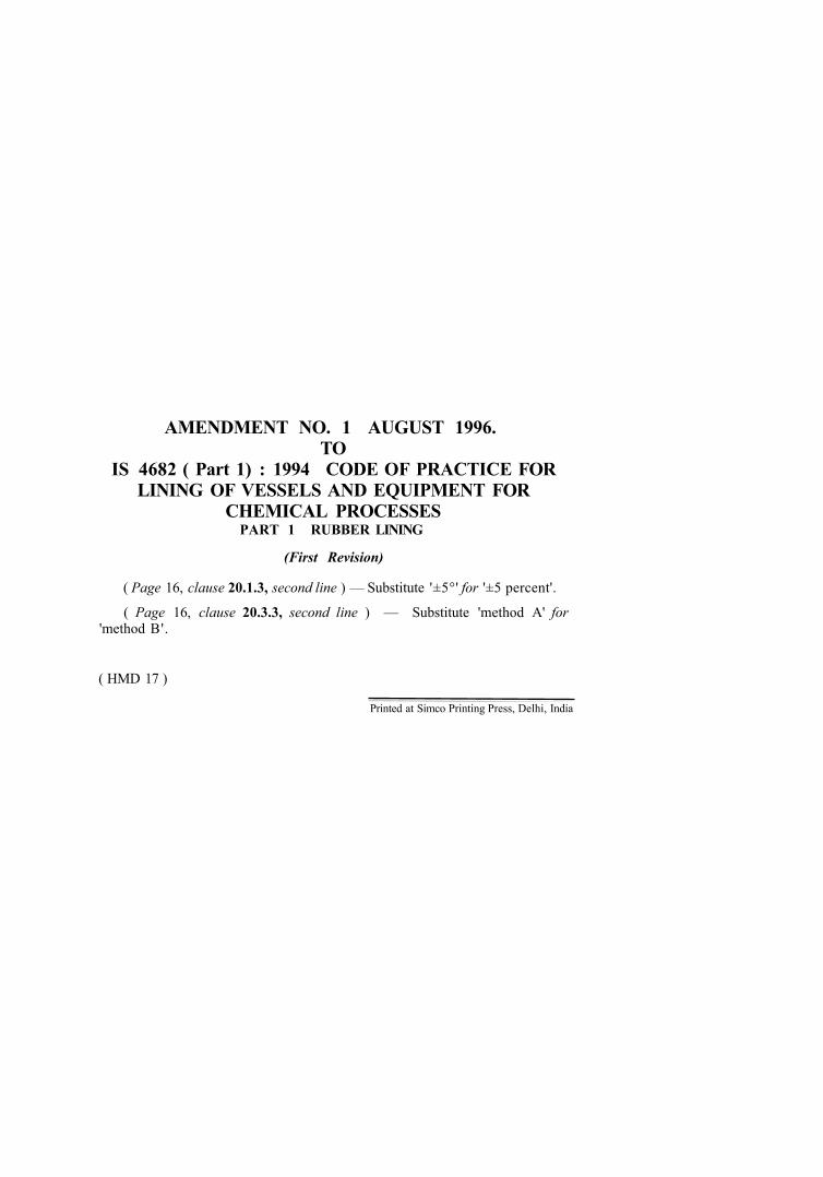
( Page 16, clause 20.1.3, second line ) — Substitute '±5°' for '±5 percent'.
( Page 16, clause 20.3.3, second line ) — Substitute 'method A' for 'method B'.
( HMD 17 )
Printed at Simco Printing Press, Delhi, India
IS 4682 ( Part 1 ) : 1994
Indian Standard CODE OF PRACTICE FOR LINING OF
VESSELS AND EQUIPMENT FOR CHEMICAL PROCESSES
PARTI RUBBER LINING
( First Revision ) SECTION 1 GENERAL
1 SCOPE 1.1 This Indian Standard (Part 1) specifies requirements for the lining of equipment for the process industries using cold rubber. It applies to equipment fabricated in metal or concrete.
1.1.1 It includes requirements for the choice of lining and its application and also requirements for inspection of the lining and the rectification of faults. The materials considered include natural and synthetic rubbers applied as unvuleanized or prevulcanized sheet.
1.1.2 Brushed or sprayed rubber linings arc not included.
NOTE — The linings may be applied at the applicator's works or on site.
1.2 It includes requirements for design and fabrication of the equipment and the state of preparation necessary for the surfaces to be lined. It also includes requirements for storage, handling, transportation and inslallation of the lined equipment.
2 REFERENCES
The Indian Standards listed in Annex A arc necessary adjuncts to this standard.
3 TERMINOLOGY
3.0 For the purpose of this standard the definitions given in IS 7503 (Parts 1, 2, 3 and 4) : 1988 shall apply, together with the following.
3.1 Purchaser The organization or individual who buys the lined equipment for its own use or as an agent for the owner.
3.2 Fabricator The organization or individual responsible for the fabrication of the equipment to be lined.
3.3 Applicator The organization or individual responsible for the application of the lining.
3.4 Inspection Authority
The body or association appointed by the purchaser (or owner) to check that the design, fabrication and lining comply with this standard.
3.5 Vulcanization
The chemical reaction resulting in the final polymerized product.
3.6 Pinhole
A small defect in the lining that would permit corrosion of the substrate under the conditions for which the lining is designed.
NOTE — The word pinhole' is synonymous with 'holiday' and 'pore'.
3.7 Blister
A gas or liquid filled cavity within the lining material or between the lining and substrate.
3.8 Scarf Joint
A joint made between two adjacent sheets of rubber by bevelling the edges of the sheets and overlapping one prepared edge on the other ( sec Fig. 7 )
4 EXCHANGE OF INFORMATION
4.1 Early consultation shall be arranged between all parties concerned with the application of this standard, to establish the following information which shall he fully documented:
i) Design and fabncation details of the equipment to be lined and provision of drawings (see 7, 8, 9 and 10).
ii) Details of gasket materials (see 7.9 and 7.10).
iii) Details of the contents of the vessels or equipment, including trace materials [.see 1.1.1.3 (a)].
1
IS 4682 ( Part 1 ) : 1994
iv) The design temperature [see 11.1.3 (b)].
v) The design pressure [see 11.13 (c)].
vi) The details of any solids to be handled [see 11.1.3 (e)].
vii) Any specific mechanical properties required of the lining including suitability for machining [see 11.1.3 (g)].
viii) The methods of heating and/or cooling [see 11.1.3 (b)].
ix) Cleaning methods, for example, water washing, solvent washing, boiling out or steaming [see 11.1.3 (a)].
x) Where the lining work will be done.
xi) Site conditions which may affect the work, for example, availability of services.
xii) Any special requirements for materials used in blast cleaning (see 13.1.1 and 13.1.2).
xiii) The rubber lining to be used (see 11.1).
xiv) The minimum thickness of the vulcanized lining and where applicable the maximum thickness (sec 12.2).
xv) The provision of test plates [see 12.1 (c)].
xvi) When the lining is to be applied outside the applicator's works and the primers and/or adhesives as applied contain solvents, the types of solvents are to be stated, together with their Hash points and threshold limit values.
xvii) Specilied adhesion system (see 11.1, 12.3 and 14).
xviii) The minimum and n)aximum allowable temperature and allowable humidity which
are required for the correct application of the lining (see 14 and 16).
xix) The minimum temperature required during the vulcanization of the lining (see 17).
xx) The vulcanization schedule, where applicable.
xxi) Inspection techniques/procedures to be employed, acceptance levels and stages of inspection (see 18 and 19).
xxii) Handling, transport storage and installation procedure [see 11.1.3 (g) and 22.1 to 22.7].
4.2 Both the definitive requirements specified in this standard and the items documented in 4.1 shall be satisfied before a claim of compliance with the standard can be made and verified.
5 COMPLIANCE
5.1 Fabricator
The fabricator shall comply with the following:
a) Section two [see 4.1 (i)];
b) Requirements given in 18.1 (a) and 18.1; and
c) Section six as agreed in 4.1 (xxii).
5.2 Applicator
The applicator shall comply with the following:
a) Section three (see also 12.1);
b) Section four;
c) Requirements given in 18.1 (c), (d), (e) and (f);
d) Requirements given in F-3;
e) Requirements given in 21; and
I) Section six as agreed in 4.1 (xxii).
SECTION 2 DESIGN, FABRICATION AND SURFACE FINISH OF EQUIPMENT TO BE LINED
6 GENERAL 6.1 The basic design, labrication and testing for mechanical reliability of the equipment to be lined shall be carried out to the appropriate Indian Standard and shall comply with 7 and 8 or 9 and 10 before the lining operation commences.
NOTE — Rubber lining will affect heat transfer and tolerances required for joints both need to be considered at the design stage of the equipment.
6.2 For the lining of used equipment, refer Annex B.
7 D E S I G N O F M E T A L E Q U I P M E N T T O B E LINED 7.1 Equipment to be lined shall be sufficiently rigid
that there is no possibility of defonnation which would result in damage to the lining during transportation, installation and operation. When stiffeners are required, they shall normally be applied to the unlined side of the equipment.
NOTE — In the case of hard rubber and ebonite linings this requirement is of particular importance.
7.2 The arrangements for the lifting of equipment shall be determined at the design stage.
7.3 The design of all equipment shall allow for access during the preparation of the surface and application of the lining and for venting of fumes evolved during the operation.
7.3.1 In completely enclosed vessels there shall be
2
IS 4682 ( Part 1 ): 1994 at least one manhole that after lining complies with IS 2825 : 1969 or IS 803 : 1976 and one additional branch of not less than 75 mm bore to permit adequate circulation of air.
NOTE — It is recommended that, where practicable, the minimutn diameter of a manhole should be 600 mm.
7.4 Riveted constructions shall not be used.
7.5 Bolted joints shall be permitted only if they can be dismantled for lining.
7.6 When calculating clearances, allowance shall be made for the thickness of the lining.
7.7 Surfaces to be lined shall be of a smooth contour.
7.8 Discontinuities, crevices and sharp projections shall be avoided.
7.9 Fittings which have to be installed after the completion of the lining process shall be designed to be lined or fabricated from materials that will not be affected by the process conditions.
7.10 Normally all connections to lined parts of equipment shall be flanged. If for any reason screwed connections are required, then these parts shall be fabricated in corrosion-resistant materials.
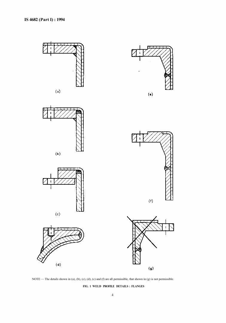
7.11 Branches and outlets, except for plain ended pipes, shall be as short as possible and flanged so that the lining may be taken over the flange face to prevent the ingress of process fluid between the lining and the substrate.
NOTE — Acceptable flange systems arc shown in Fig. 1.
7.11.1 Plain-ended pipes shall be designed so that the lining may be turned over the end and the outside of the pipe.
7.11.2 Where pads are required they shall be designed as shown in Fig. 1 (d). Drilled and tapped holes in pads for studs shall not penetrate the shell of the equipment.
7.12 Heating coils, immersion heaters and sparger pipes shall be installed after the completion of the lining process and shall be located so that no part is closer than 100 mm from a lined surface. In the case of nozzles through which heating coils, etc, enter equipment, a smaller clearance is permitted provided that the temperature of the pipe through the nozzle does not exceed 80°C. In no case shall this clearance be less than 25 mm. Fluids introduced through sparger pipes or dip pipes shall not impinge directly on to the lining. External heating of equipment shall not be permitted without full consultation with the applicator of the lining.
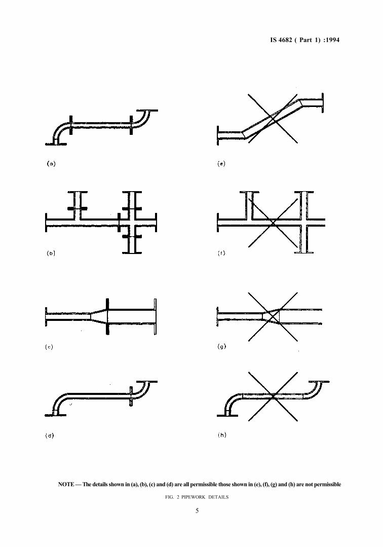
7.13 The design of pipework shall be such as to allow ready access to welds and bends for weld and surface preparation.
NOTH — Pipe systems made from straight lengths with separate standard bends and tees meet this requirement. Bends should not be greater than 90°.
7.13.1 Where pipe systems include ' non-standard' fittings their suitability for lining shall be established [see 4.1 (i)]. Suitable arrangements are illustrated in Fig. 2.
7.13.2 The maximum dimensions of pipes and fittings which can be rubber lined shall be determined during the exchange of information [see 4.1 (i)]. Typical maximum lengths of straight pipe which can be rubber lined are detailed in Table 1.
Table 1 Maximum Length Between Flanges (Clause 7.13.2)
Nominal Pipe Size mm
25 32 40 50 65
80 to 600
Maximum Length Between Flanges
mm
2 000 2 500 3 000 3 500 4 000 6 000
7.13.3 Pipes less than 25 mm diameter shall not be rubber lined. Pipes less than 250 mm diameter shall be of seamless construction only. Screwed fittings shall not be rubber lined.
7.13.4 Where flat face or raised face flanges are used they shall be welded square to the pipe or fitting according to normal manufacturing tolerances.
7.13.5 Flanges which are attached to a pipe by fillet welding (for example slip-on flanges) shall be suitably vented to allow any air trapped between fillet welds to escape to atmosphere during lining and vulcanizing.
NOTH — This may be accomplished by using a vent hole in the tlange, providing this meets piping design standard requirements.
8 FABRICATION OF METAL EQUIPMENT TO BE LINED
8.1 All welds shall be continuous on surfaces to be lined.
NOTE — Butt welds art preferred to fillet welds.
8.1.1 Stitch welding, spot welding and other non-continuous welding proces.ses shall not be used.
8.2 Weld surfaces shall be smooth. Some welding procedures provide surfaces of adequate smoothness but, in other cases surfaces shall be ground wholly or partly to remove weld ripples. The grinding process shall be done so that the remaining weld does not have sharp edges.
3
IS 4682 (Part I) : 1994
NOTE — The details shown in (a), (b), (c), (d), (c) and (f) are all permissible, that shown in (g) is not permissible.
FIG. 1 WELD PROFILE DETAILS : FLANGES
4
IS 4682 ( Part 1) :1994
NOTE — The details shown in (a), (b), (c) and (d) are all permissible those shown in (e), (f), (g) and (h) are not permissible
FIG. 2 PIPEWORK DETAILS
5
IS 4682 ( Part 1) : 1994
8.3 Welding procedures shall be chosen to avoid porosity on the side of the weld to be lined.
NOTE — It is preferable that capping runs are applied to the lining side in order to minimize this effect.
8.3.1 All welds shall be free from the following surface defects :
a) Undercutting, b) Cracks, c) Porosity,
d) Any other type of surface cavity, and c) Lack of fusion.
8.3.2 Weld defects that are exposed either on initial inspection or after blast cleaning shall be repaired.
8.3.3 Repairs shall be by grinding or by welding (with or without subsequent grinding) provided that the requirement for equipment design and fabrication are met.
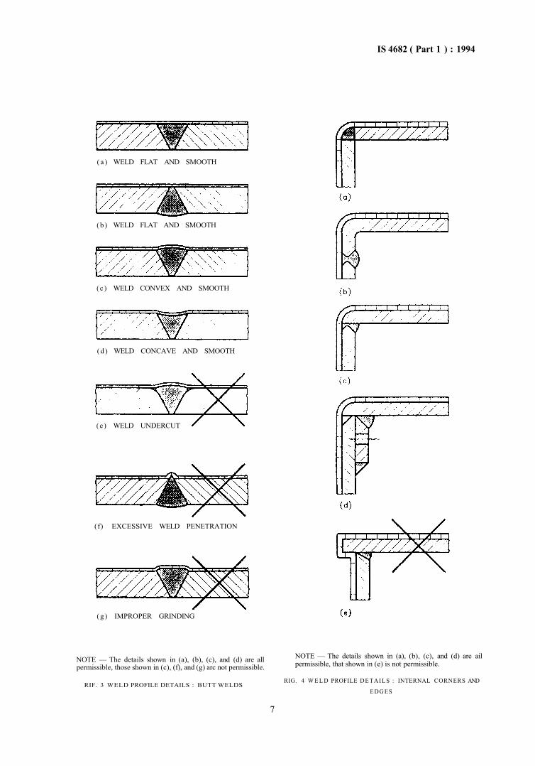
8.4 Weld profile details shall be generally in accordance with Fig. 1 and Fig. 3 to 6.
NOTE — Incorrect details are also illustrated.
8.5 Filler materials, such as resin, putties, fillers and low melting point solders and brazes, shall not be used.
8.6 Before the equipment is passed for lining, all allachments to be made by welding, for example lagging cleats and lifting lugs, shall be complete.
8.7 All drilling shall be completed before the equipment is passed for lining. Holes to be lined shall have their edges radiused.
8.8 External corners and edges shall be furnished to a radius of minimum 3 mm or equal to the thickness of the rubber, whichever is higher. For internal comers and edges to a radius of minimum 6 mm or twice the rubber thickness whichever is higher.
NOTE — For typical edge configurations, see Fig. 4 and 5.
8.9 Castings including cast iron shall be produced by foundry techniques which give dense smooth surfaces free from slag, sand and inclusions, shrinkage cavities, scabs, cracks, porosity and bums and the entrapment of air in surface defects.
8.9.1 Removal of defects shall be by welding and grinding or by grinding alone. Grinding alone shall be used only for small defects such that the ground cavity blends smoothly with the casting surface and does not reduce the sound wall of the casting below the requirements of the design standard. For larger defects welding shall be used and the repair weld shall be ground flush such that it does not impair the requirements of the design standard.
8.10 Where there is a requirement that a rotating part shall be balanced, then this balancing shall be done both before and after lining.
8.11 All slag, anti-spatter compounds or similar materials shall be removed. All weld spatter shall be removed by chipping and/or grinding.
8.12 Surface defects such as scores, pitting and rolling defects shall be removed by grinding, or where necessary repaired by welding provided that the requirements of design and construction are met.
8.13 Surfaces shall be presented to the lining applicator in a clean condition free of all contamination, for example oil, grease, temporary protective coating, such that no pre-treatment is required other than any grit blasting which is to be part of the lining process.
9 DESIGN OF CONCRETE EQUIPMENT TO BE LINED
9.1 Whilst it is not possible to eliminate shrinkage cracks in conerete, the design shall be such that structural cracking is eliminated. Particular attention shall be paid to avoiding cracking due to thermal stresses. The ability of the lining to accommodate cracking of the concrete shall determine the selection of the rubber. Equipment shall be designed to IS 456 : 1978.
9.2 If necessary, extra reinforcements shall be used and construction joints treated so as to promote a bond between adjacent areas of concrete. Expansion joints create special problems in lining and shall not be used without consultation between the purchaser and the applicator of the lining.
9.3 Pipes and fittings shall be designed with puddle flanges and cast into the concrete. Where necessary such fittings shall be designed in a concrete resistant material. Pipes and fittings shall normally be rubber lined before being cast into the concrete.
9.4 The arrangements for the blast of equipment shall be determined at the design stage.
9.5 The design of all equipment shall allow for access during the preparation of the surface and application of the lining, and for venting of fumes evolved during the operation. In completely enclosed vessels there shall be at least one manhole complying, after lining, with IS 2825 : 1969 or IS 803 : 1976 and one additional branch of not less than 75 mm bore to permit adequate circulation of air.
NOTE — It is recommended that, where practicable, the minimum diameter of a manhole should be 600 mm.
9.6 All corners shall be designed to be formed with a 45° fillet with a minimum leg length of 20 mm.
9.7 All equipment to be placed below ground level or subject to external water pressure shall be provided with a waterproof barrier on the outside of the equipment.
6
IS 4682 ( Part 1 ) : 1994
( a ) WELD FLAT AND SMOOTH
(b) WELD FLAT AND SMOOTH
(c ) WELD CONVEX AND SMOOTH
(d ) WELD CONCAVE AND SMOOTH
(e) WELD UNDERCUT
(f) EXCESSIVE WELD PENETRATION
(g) IMPROPER GRINDING
NOTE — The details shown in (a), (b), (c), and (d) are all permissible, those shown in (c), (f), and (g) arc not permissible.
RIF. 3 WELD PROFILE DETAILS : BUTT WELDS
NOTE — The details shown in (a), (b), (c), and (d) are ail permissible, that shown in (e) is not permissible.
RIG. 4 W E L D PROFILE D E T A I LS : INTERNAL CORNERS AND
EDGES
7
IS 4682 ( Part 1 ) : 1994
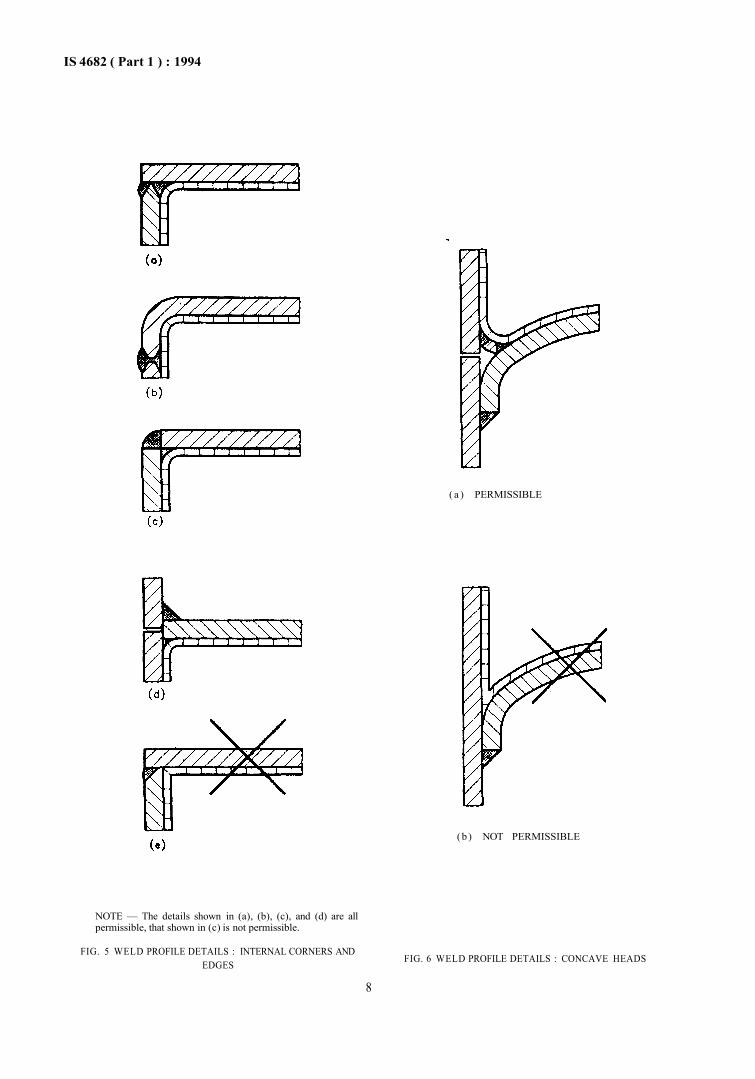
NOTE — The details shown in (a), (b), (c), and (d) are all permissible, that shown in (c) is not permissible.
FIG. 5 WELD PROFILE DETAILS : INTERNAL CORNERS AND EDGES
( a ) PERMISSIBLE
(b ) NOT PERMISSIBLE
FIG. 6 WELD PROFILE DETAILS : CONCAVE HEADS
8
IS 4682 (Part 1) : 1994 9.8 All equipment shall be designed with a minimum of 20 mm of concrete over reinforcement.
10 CONSTRUCTION OF CONCRETE EQUIPMENT TO BE LINED
10.1 Concrete equipment shall be constructed in accordance with the requirements of IS 3370 (Parts 1, 2, 3 and 4) or IS 456 : 1978 as appropriate.
10.2 Proper curing of the concrete shall be ensured by the use of curing membranes. If shuttering is removed in under 7 days a curing membrane shall be applied. Concrete equipment shall be allowed to cure tor 28 days before the work of lining proceeds. Concrete hardening solutions shall not be used.
10.3 Equipment which is slip formed shall be bagged
as the concrete leaves the formwork before the curing membrane is applied.
NOTE — This process will reduce the amount of laitance.
10.4 All surfaces not cast against shutters shall be finished with a wooden float. Curing membranes shall be applied and not disturbed for 7 days. 10.5 Any steps in the concrete due to misalignment of shutters or surplus material formed because of gaps at joints in shutters shall be dressed off and ground smooth. 10.6 All holes left after removal of ties to secure and align formers shall be filled. Any surface defects such that the aggregate is exposed shall be filled. The material used for filling shall be a sand/cement grout with a high cement content or a sand/cement water miscible epoxy resin grout or an epoxy mortar.
SECTION 3 SELECTION AND QUALITY OF LININGS
11 SELECTION OF LINING
11.1 Linings referred to in this standard shall include natural and synthetic rubbers which shall be bonded to the substrate.
NOTES 1 Rubber linings are used for a number of different duties including protection against corrosive environments, protection against abrasion or erosion and prevention of contamination of products. 2 The properties of lining materials depend not only upon the type of rubber but upon the compounding (mixing) with other ingredients, e.g. fillers, vulcanizing agents, etc. Some applicators produce their own compounds and sheet, others buy from external sources.
11.1.1 It shall be the responsibility of the applicator, unless othenvise agreed [see 4.1 (xiii)], to select a compound suitable for the duty stated by the purchaser. In order to define the rubber used for a lining, a compound reference as well as the rubber type shall be stated by the applicator during the exchange of information.
11.1.2 The adhesive system used for bonding the rubber to the substrate shall depend upon the type of rubber and the method of vulcanization. It shall be the responsibility of the applicator to select an adhesive system which will provide an adequate bond between rubber and substrate.
NOTE — A description of the rubbers used for lining and a guide to their properties are given in Annex C. Applicators will have more extensive knowledge of particular compounds and some purchasers will have particular knowledge of past performance which will help in the selection of a suitable lining material.
11.1.3 When an applicator is to select and apply the lining full details of the duties of the equipment shall be supplied. The selection of the rubber lining shall be based on the following information:
a) General — Full analysis of the contents of the equipment including constituents present
in small and trace quantities, and details of cleaning operations.
b) Temperature of materials to be handled : 1) Normal operating temperatures; 2) Maximum and minimum temperatures;
and 3) Cycle of temperature variation.
c) Degree of vacuum or pressure : 1) Normal operating pressure; 2) Maximum and minimum pressure; and 3) Cycle of pressure variation.
d) Cycle of operations — Whether batch or continuous process.
e) Abrasion and erosion — Details of amount, particle size and physical characteristics of the suspended matter together with rates of flow.
f) Mechanical damage — Any difficulties expected in the handling and final siting of the equipment or any vibration of equipment and the possibility of mechanical damage.
g) Special requirements — For example extremes of weather likely to be encountered during the handling, transport and storage of the equipment.
11.1.4 When selecting materials account shall be taken of Annex D.
11.2 Unless previous experience demonstrates that a lining will be suitable for a particular duty, appropriate testing shall be carried out.
NOTE — Attention is drawn to the dangers of short-terms testing and the need to reproduce service conditions accurately.
11.2.1 Where it is not possible to place samples in process streams, service conditions shall be simulated.
9
IS 4682 ( Part 1 ) : 1994 Where it is known that a lining has to withstand an environment where heat transfer is made through the lining, the heat transfer condition shall be maintained during the test.
11.2.2 Substances including dissolved gases present in a process stream in trace quantities only shall be added to the test liquors.
12 QUALITY OF LINING
12.1 General
When the applicator is responsible for selecting the grade of lining to be applied, he shall verify that such a lining shall withstand the chemical and physical conditions specified in 11. When the purchaser selects the grade of lining to be applied, the applicator shall be responsible only for the correct application. The applicator shall in either case :
a) State the reference number of the rubber to be used for the lining.
b) State the hardness of the rubber after vulcanization.
c) Supply test pieces such as panels to which the rubber has been applied and which will serve as reference samples [see 4.1 (xv)].
12.2 Thickness of the Lining
12.2.1 The thickness of the lining shall be selected to suit the chemical and/or mechanical duty during the exchange of information between the applicator and the purchaser [see 4.1 (xiv)].
NOTES
1 The minimum thickness which is acceptable is 3 mm, but thickness of 4 mm, 5 mm or 6 mm should be chosen as required to meet particular operating conditions.
2 Thicknesses greater than 6 mm are normally applied in two or more layers.
12.2.2 Normally the thickness refers to the rubber sheet as applied to the substrate. If the purchaser requires the nominated thickness to apply to the finished lining this shall be stated during the exchange of information [see 4.1 (xiv)].
12.3 Bonding of the Lining
The rubber lining shall be bonded to the substrate. The adhesive system shall be suitable for the type of rubber and for the service conditions. The applicator shall be responsible for the selection of the adhesive system and shall produce evidence that the adhesive system will produce the bond required between rubber and substrate when the rubber is applied under the conditions of vulcanization [see 4.1 (xvii)].
SECTION 4 METHOD OF LINING
13 SURFACE PREPARATION
13.1 Metal
13.1.1 All surfaces of carbon steel and cast iron to be lined shall be blast cleaned, unless otherwise permitted by the purchaser.
13.1.2 In the case of metals other than carbon steel and cast iron, methods of preparation of the substrate shall promote an acceptable bond between the substrate and the lining. The appropriate technique of substrate preparation shall be established with the lining contractors [see 4.1 (xii)].
13.1.3 All surface dust, residues and debris left on the surface after blast cleaning shall be removed, thoroughly.
13.1.4 The lining process shall start as soon as possible after blast cleaning is complete and before any visible rusting occurs. Unless maintained in a dehumidified atmosphere application of the primer shall commence within 4 hours. Should signs of rusting occur then the surface shall be prepared again to the required standard (see 13.1.1).
13.1.5 All surfaces to be lined shall be maintained at a temperature of at least 3°C above the dew point
throughout the preparation and lining processes. If there is a risk that this condition will not be maintained owing to ambient conditions, dehumidifying and/or heating equipment shall be used.
13.2 Concrete
13.2.1 External corners not formed with a chamfer shall be rubbed down to a radius of at least 3 mm or the thickness of the rubber lining whichever is greater. For internal corners radius should be at least 6 mm or twice the rubber lining thickness whichever is greater.
13.2.2 Lining of concrete equipment shall not proceed until at least 28 days after the concrete was cast and when the free water content is down to a level specified in 4.1 (i).
NOTES
1 Satisfactory adhesion of rubber lining to concrete depends upon the water content of the concrete. It is desirable that the free water content is less than 5 percent. If the concrete mix used is carefully controlled it is possible that after a curing period of 28 days the water content will be down to 5 percent but the required curing period may be longer.
2 There are no reliable methods for measuring the absolute water content of concrete although moisture meters may be useful in determining problem areas. It is advisable to line a test area and measure the adhesion before proceeding with a complete lining.
10
IS 4682 ( Part 1 ) : 1994 13.2.3 Surfaces to be lined shall be treated to remove laitance and shutter release agents. Of the two possible methods for this operation the one preferred is blast cleaning. The blast cleaning process shall be controlled so that all laitance is removed and exposure of the profile of the aggregate kept to a minimum. After blast cleaning all dust and debris shall be removed.
NOTE — The alternative method of removing laitance is that of acid etching. The process is more difficult to control on vertical and overhead surfaces and the presence of shutter oils will reduce its effectiveness. The thickness of the laitance of a concrete surface varies considerably and it is very important that acid is allowed to dwell on the surface a sufficient length of time to remove all laitance. When acid etching is used the next operation is water washing of the concrete, followed by a drying process.
13.2.4 Unless the lining material will fill or effectively bridge the large number of small holes (of varying diameter and depth) that invariably remain in the concrete surface following the removal of laitance, then these holes shall be filled before the work of lining commences.
NOTE — One material recommended for this purpose is a smooth paste made from a water miscible epoxy resin and a fine filler and cement (see 10.6).
13.2.5 After removal of laitance all surfaces to be lined shall be maintained at a temperature at least 3°C above the dew point throughout the preparation and lining processes. If there is a risk that this condition will not be maintained owing to ambient conditions or a change in ambient conditions, dehumidifying and/or heating equipment shall be used.
14 ADHESION SYSTEM AND APPLICATION
14.1 The adhesive system shall be such that the required level of adhesion between the lining and the substrate is achieved upon completion of the lining process.
NOTE — The adhesive system may consist of one or more individual layers. The primer already applied to the substrate may also be considered as part of the adhesive system.
14.2 The adhesives shall be applied to the primed substrate surface by brush, roller or spray, any solvents in the adhesive being allowed to evaporate between the application of successive coats or subsequent application of the lining.
15 PRODUCTION OF LINING MATERIAL
15.1 Thickness Tolerance The thickness tolerance on nominal dimensions of the rubber sheet shall be ± 10 percent.
15.2 Freedom from Imperfections The sheet shall be free from blisters or other imperfections which would adversely affect the quality of the lining.
153 Unvulcanized Lining Materials Lining materials shall be produced using a calender, extruder or roller die.
a) When linings arc produced by calendering, multiply construction shall be employed.
NOTE — The minimum number of plies employed in the manufacture of a finished sheet depends upon the rubber compound. A guide to the number of plies related to a given thickness is given below :
Thickness of Lining,
mm
3 to 5
6
Minimum Number of Plies
3
4
b) When roller die or extrusion methods are used for the production of lining materials then single-ply or multi-ply sheets arc permissible.
15.4 Pre-vulcanized Lining Materials
The unvulcanized lining sheet shall be prepared in accordance with 15.3 and shall then be vulcanized by heating (normally under pressure in an autoclave) or by a rotary vulcanization process.
16 APPLICATION OF THE SHEET TO THE SUBSTRATE
16.1 General
Detailed methods of working are not specified in this standard but the requirements specified in 16.2 to 16.5 shall be met according to whether unvulcanized sheet, prc-vulcanized sheet or a combination of the two is being used.
16.2 Preparation of Lining Sheet
16.2.1 In the case of unvulcanized sheet any preshrinking necessary shall be carried out as a first step.
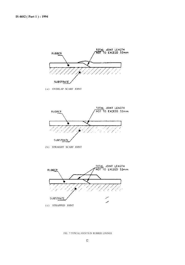
16.2.2 Individual sheets shall be tailored to fit the surface to be lined. Edges shall be prepared according to the type of joint to be used. Types of joints are illustrated in Fig. 7.
16.2.2.1 The details of edge preparation shall be as follows :
a) Overlap scorf joint — The edges shall be bevelled at 30° to 35°.
b) Simple scarf joint — The edges shall be bevelled at 40° to 50°.
c) Cover straps — The edges shall be bevelled at 30° to 35°.
16.3 Joints
Depending upon the type of sheet being applied and the method of lining, one of the following types of joint shall be used.
11
IS 46S2 ( Part 1 ) : 1994
( a ) OVERLAP SCARF JOINT
( b ) STRAIGHT SCARF JOINT
( c ) STRAPPED JOINT
FIG. 7 TYPICAL J O I N T S IN RUBBER LININGS
12
IS 4682 ( Part I ) : 1994 a) Overlap scarf joint — This type of joints is
illustrated in Fig. 7(a). The total length of the contacting surface between adjacent sheets shall be a minimum of four times the sheet thickness but shall not exceed 32 mm at any point. Overlap scarf joints will tend to affect the flow in pipes and that effect may be significant in the case of small bore pipes, a fact which shall be considered when the equipment is designed. Overlap scarf joints on mating surfaces shall be dressed as necessary to allow efficient sealing when assembled.
NOTE — It is preferable that overlap scarf joints should be made to that the overlap follows the direction of flow.
b) Straight scarf joints shall be made as illustrated in Fig. 7(b).
c) Strapped joints shall be made as. illustrated in Fig. 7(c). The scarf joint in the parent sheet shall pass a spark test before the cover strap is fitted. The cover strap with edges bevelled shall be aligned centrally over the joint. The maximum path from an edge of the strap to the substrate shall not exceed 32 mm.
NOTE — The thickness of the strap may be less than the thickness of the lining.
d) Joints in multiple layer linings shall be scarfed as illustrated in Fig. 7 (b). Joints within one layer shall be offset relative to joints on adjacent layers. The distance between joints on adjacent layers shall be a maximum consistent with the geometry of the equipment.
164 Pretreatment of Lining Sheets
The contacting fate of the lining sheet shall be made tacky so as to adhere to the adhesive layer already on the substrate. Tackiness shall be produced by either wiping with a suitable solvent or the application of a coat of adhesive. In either case solvents shall be allowed to evaporate before the sheet is applied to the surface to be lined.
16.5 Fitting of Lining Sheet to the Substrate
16.5.1 Exclusion of Air
In the application of lining air shall be excluded between the substrate and lining and between adjacent layers in multilayer linings.
NOTE — Exclusion of air is achieved by pressing the lining against the substrate with a roller or by other means in a systematic manner. Suitable tools should be used to ensure complete contact of rubber to substrate at changes of direction and rubber to rubber at joints.
16.5.2 Continuity of Lining
When fitting of the sheet is complete all sheets and joints whether overlap, scarf, straight scarf or strapped joints shall be free from pinholes and other defects.
17 VULCANIZATION
17.1 General
17.1.1 Vulcanization of the lining shall be carried out by one of the following methods :
a) Autoclave vulcanization, b) Using equipment as its own autoclave, c) Steam or hot air vulcanization at ambient
pressure,
d) Hot water vulcanization, and
e) Self vulcanization at ambient temperature.
NOTES
1 The method employed depends upon the design and size of the equipment It may be necessary to shield the equipment to reduce heat losses which would otherwise lengthen the duration of vulcanization when using methods (b), (c) or (d) above.
2 The duration of vulcanization will depend upon the method used and the composition of the lining material. More information on vulcanization is provided in Annex E.
17.1.2 With the agreement of the applicator [see 4.1 (xx) and (xxi)] interruption of vulcanization shall be permitted to detect and repair any faults present. The equipment shall then undergo further beat treatment to complete the vulcanization. An inspection for faults shall be carried out in accordance with section five.
17.2 Methods of Vulcanization
17.2.1 Autoclave Vulcanization
The equipment shall be placed in an autoclave which is then heated to the required temperature and pressure.
17.2.2 Using Equipment as Its Own Autoclave
With all outlets sealed and a steam trap condensate drain attached to a convenient outlet to ensure continuous removal of condensate, saturated stream shall be injected until the equipment is pressurized to a predetermined pres.sure. The pressure shall be within the design pressure limits of the equipment. Precautions shall be taken against failure of the steam supply since, in such cases, condensation can cause a vadium and collapse the vessel.
17.2.3 Steam or Hot Air Vulcanization at Ambient Pressure
With outlets covered to reduce steam losses and provision made to drain condensate from the equipment, the steam shall be injected until the vulcanization temperature is attained. This temperature shall be maintained for the required time period. Attention is drawn to 17.2.2 regarding failure of steam supply.
NOTE — Hot air may be used as an alternative to steam in some cases provided that the temperature and beat input can be achieved.
13
IS 4682 ( Part I) : 1994 17.2.4 Hot Water Vulcanization With all outlets below the top flange sealed off and the equipment partially filled with water steam shall then be injected into the water, raising the water level and temperature. If the water reaches boiling point before the equipment is full, further water shall be added to attain the required level. The temperature shall then be maintained for the required time period while maintaining the water level.
17 2.5 Self Vulcanization at Ambient Temperature
Such robber linings shall be specially designed so that they are capable of vulcanizing under ambient conditions.
NOTE — The time to vulcanize is temperature-dependent and at temperatures below 15°C it may be necessary to use supplementary heating in order lo reduce vulcanization times to an acceptable period.
SECTION 5 INSPECTION AND TESTING
18 RESPONSIBILITY FOR INSPECTION AND TESTING
18.1 The fabricator of the equipment and the applicator of the lining when requested shall provide a certificate of inspection and testing. The stages of inspection shall be as follows:
a) The equipment as fabricated.
b) The equipment after preparation of welds and edges in the case of metals; surfaces and edges in the case of concrete.
c) The equipment after blast cleaning.
d) The materials to be used in the lining process.
e) After the lining has been applied and before vulcanization.
f) When the arrangements are made to interrupt vulcanization.
g) After vulcanization is complete.
h) Whenever remedial work is carried out.
18.2 In cases where the purchaser requires independent inspection of the work (i.e. by the inspection authority) at various stages, those stages shall be defined [see 4.1 (xxi)].
19 INSPECTION
19.1 Surface Cleanliness and Profile of Metal Surfaces
19.1.1 Blast-cleaned surfaces shall be inspected to ensure that they comply with 13.1. 19.1.2 Reference photographs or plates shall be used to establish the level of surface cleanliness (see 13.1.3). 19.1.3 If inspection of equipment after blast cleaning reveals defects in material or welds, the applicator shall inform the fabricator and/or the purchaser and any remedial action shall be determined after consultation between the parties concerned [see 4.1 (xxi)].
19.2 Concrete Surface Concrete surfaces shall be inspected to sec that they
are free from laitance and that surface defects are properly filled.
19.3 Quality of the Lining and Bonding Materials
Before proceeding the applicator shall ensure that all materials to be used in the lining process are visually examined and, where appropriate, physically and practically tested to connrm that they are in an acceptable condition. For the unvulcanized rubber sheeting this shall include:
a) Visual examination to ensure that it has no imperfection which could significantly affect the performance of the fmished vulcanized lining.
b) Visual and physical examination to ensure that it has been prepared in accordance with section four and that the actual thickness is within ± 10 percent of the specified thickness.
c) A test to ensure that the sample taken from each roll achieves the correct hardness when vulcanized in accordance with the customary practice of the applicator.
194 Visual Appearances of the Lining
19.4.1 Inspection for visible defects shall be carried out over the entire surface of the lining in a good light, attention being paid to any areas of mechanical damage, cuts, blisters, lack of adhesion and poor jointing.
19.4.2 If the applicator finds a defect prior to vulcanization it shall be removed and the area overlaid with unvulcanized rubber of the same type as the original unvulcanized rubber on to which it is bonded. After subsequent vulcanization the area concerned shall be considered identical to a lap joint or seam and thus fully acceptable.
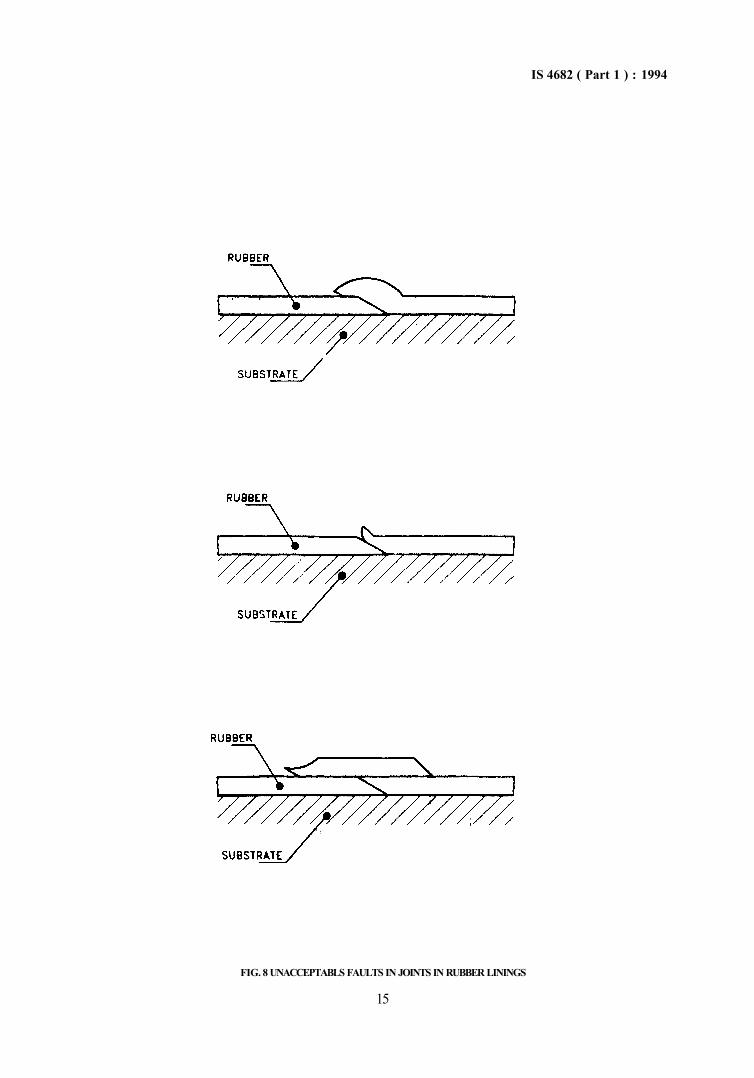
19.4.3 All scarf joints shall be closely inspected. Any separation of the joint shall be investigated (see Fig. 8). If the extent of the separation is small then the rubber shall be ground bock. If the separation of the rubber is extensive then the joint and rubber adjacent to the joint shall be removed and replaced.
19.4.4 To repair defects found after vulcanization, the surface of the lining local to the defect shall be prepared by abrading. Adhesive and a patch of
14
IS 4682 ( Part 1 ) : 1994
FIG. 8 UNACCEPTABLS FAULTS IN JOINTS IN RUBBER LININGS
15
IS 4682 ( Part 1 ) : 1994 unvulcanized rubber both of the same type as used for the lining shall then be applied. The size of this patch shall not be greater than 25 mm in any direction beyond the defect. The patch shall then be vulcanized. After rectification, the repaired area shall be tested for pinholes. Minor wrinkles and surface markings which have no significant effect on the performance of the lining shall be acceptable.
NOTE — After vulcanization defects such as blisters, Wow holes, small cracks or scuffed areas in the lining may be found. When such faults are discovered after vulcanization the defect may be patched.
20 TESTING
20.1 Hardness Tests
20.1.1 Hardness testing shall be carried out on completion of vulcanization in accordance with IS 3400 (Part 2): 1980. If after initial testing any further vulcanization is required, the lining shall be re-tested and shall meet the agreed hardness (agreed by contractor and user) at all points.
20.1.2 Hardness testing shall be carried out on a flat smooth surface. In vessels where readings cannot be taken on the surface of the lining, buttons shall be provided in positioas to be agreed between the purchaser and the lining contractor. If the surface is too rough, a light local scraping or buffing may be carried out to facilitate testing.
20.1.3 Readings obtained shall conform to the specified hardness of the compound within ±5 percent. A minimum of three hardness readings shall be taken for each square metre of lining. Where a reading is outside the agreed range, further readings shall be taken on the same panel to ensure the general level of hardness. Where repairs have been carried out or where marking is feasible, the areas concerned shall be separately tested.
20.2 Continuity of Lining (High Frequency Spark Test)
20.2.1 Testing for pinholes and other discontinuities shall be carried out :
a) When the rubber has been applied and before vulcanization.
b) After interrupted vulcanization.
c) After complete vulcanization.
d) After any remedial work.
20.2.2 When tested in accordance with the method described in Annex F, the linings shall be continuous i.e free from pin holes, crack and lack of adhesion.
20.3 Bond Strength Tests
20.3.1 All open edges, for example flanges, shall be examined by hand for evidence of poor bond strength.
If further evidence is required to show that the bond between the substrate ind the rubber is satisfactory the provision of test samples shall be specified during the relevant discussions at an early stage [see 4.1 (xvii)).
NOTE — Because there is DO quantitative non-destructive test for assessing the bond strength between a rubber lining and the substrate no routine bond strength tests are specified for the actual lining as part of the inspection procedure. The bond strength for a particular combination of substrate, rubber and adhesive system may be established by laboratory testing.
20.3.2 Test samples shall consist of pieces of substrate, similar to that used in the manufacture of the equipment, to which has been applied rubber of the same mix and thickness used for the main lining. The adhesive system shall be the same as that used for lining. The conditions of application shall be the same. Vulcanization shall be carried out at the same time as the lining, in the same autoclave or inside the equipment when vulcanization takes place outside of an autoclave.
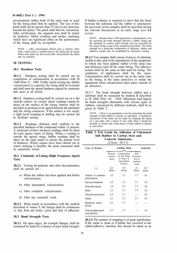
20.3.3 The bond strength between rubber and a substrate shall be measured by method B described in IS 3400 (Part 14) : 1984. Minimum load figures for bond strengths obtainable with various types of rubbers, vulcanized by different methods, shall be as given in Table 2.
NOTE — There is no quantitative test for measuring the bond strength of hard rubber or ebonite to substrates. A qualitative assessment of the bond can be made by chipping the lining on a test plate with a chisel 25 mm wide when it should be possible to loosen only small pieces of hard rubber or ebonite at each blow.
Table 2 Test Loads for Adhesion of Vulcanized Soft Rubber to Carbon Steel and
Concrete Substrates (Clause 20.3.3)
Type of Rubber
(1)
Natural of synthetic polyisoprene Styrene-butadiene
Polychloroprenc Butyl Ethylene-propylene Nitrilc
Butadiene and/or blends
Chlorosulphonated polyethylene
Carbon Steel Concrete
Pressure Vulcani-zation
(2) kN/m
3.5
3.5
3.5 3.5 3.5 3.5
3.5
2.7
Vulcanization by Hot Water or Steam at Atmosphcric
Pressure
(3) kN/m
2.7
2.7
2.7 2.7 2.7 2.7
2.7
2.7
Self Vulcaniza-
tion at Ambient
Temp
(4) kN/m
2.7
2.7
2.7 2.7
— 2.7
—
—
(5) kN/m
1.0
1.0
1.0 1.0 1.0 1.0
—
1.0
20.3.4 The manner of stripping is of great significance. If the metal is clean or if failure has occurred at the rubber/adhesive interface this should be taken as an
16
IS 4682 ( Part 1 ) : 1994 indication of an unsatisfactory bond. A properly bonded sample should leave traces of rubber sheet adhering to metal indicating failure within the rubber.
20.4 Lining Thickness Check
The thickness of the lining shall be checked. Where direct measurement is not possible a suitable thickness metal shall be used.
20.5 Hydraulic Testing of Lined Equipment
Normally pressure testing of equipment is completed before the commencement of the lining operation. When specified, pressure tests shall be carried out [see 4.1 (xxi)]. The joint rings used for this test shall be of the same material and the same dimeasioas as those specified for the final service conditions. During a pressure test no leakage shall occur. The lining shall be subsequently reinspected for defects.
20.6 Vacuum Testing of Lined Equipment
When specified, a vacuum test within the design limits of the equipment shall be carried out by evacuating the lined equipment with the appropriate joint rings in position, to a specified vacuum [see 4.1 (xxi)]. The vacuum shall be maintained for a specified
period (normally one hour). The lining shall be subsequently reinspected for defects.
21 RECTIFICATION OF FAULTS IN FULLY CURED LININGS
21.1 When rectification of faults is to be made in linings which are fully vulcanized special attention shall be paid to the problems of achieving adhesion between the new rubber and the vulcanized lining.
21.2 With all linings a patch which extends 25 mm beyond the area to be repaired shall be abraded to promote adhesion.
21.3 When priming of the substrate is an essential part of the system the first step after preparation shall be to establish whether the primer is intact. If the primer is damaged when it shall be repaired before the rest of the work proceeds.
21.4 Rectification of faults using other than the original material used for the lining shall only be permitted with the written permission of the purchaser.
21.5 After all rectification work the lining shall be subject to inspection as appropriate and in particular to continuity testing.
SECTION 6 STORAGE, HANDLING, TRANSPORTATION, INSTALLATION AND MAINTENANCE
22 GENERAL
22.1 Lined equipment shall be stored under cover or in a protected compound. When necessary, linings shall be shielded from direct sunlight.
22.2 All branches, manholes and other openings shall be protected from mechanical damage by using wooden blanks or other suitable material.
22.3 Lifting shall be arranged so that chains and other lifting aids do not come into contact with lined surfaces.
22.4 High local loads on lined surfaces shall be avoided.
22.5 Loose fittings shall not be placed inside lined equipment whilst it is being transported.
22.6 Responsibility for arranging transport of lined equipment will vary and whoever is responsible (purchaser, fabricator or applicator) shall instruct the carrier about the precautions in handling [see 4.1 (xxii)].
22.7 It is essential that the purchaser issues instructions to those responsible for installation on the handling procedures and special reference is made to the need to wear soft clean footwear when entering lined equipment and this need to protect lined surfaces from ladders and scaffold poles.
23 MAINTENANCE
23.1 Maintenance of Rubber Lined Equipment
23.1.1 It is recommended that all rubber lined plant and equipment should be thoroughly inspected at the end of the first year of service. If its condition is satisfactory and it is not subject to statutory inspection after a lesser period some major users do not then inspect again for a further 5 years. Others refer to inspect at more frequent intervals.
23.1.2 When carrying out inspections it is normally sufficient if there are visual, supplemented by hardness tests using a hand meter. If blisters or other evidence of failure are discovered then an electrical continuity test is essential.
23.1.3 It is essential that personnel be instructed in the proper procedures to be adopted when entering rubber-lined vessels. A clearance certificate should always be obtained from the appropriate authority before doing so. The following points should be observed :
a) Personnel should not wear studded boots or other footwear likely to cause damage. Rubber-soled shoes are to be preferred.
b) In cases where solid deposits have to be removed the use of metal spades or other tools is to be avoided. Wooden or lined implements should be used.
17
IS 4682 ( Part 1 ) : 1994
c) The ends of ladders or scaffolding likely to come in contact with the rubber lining should be covered in such a way that damage is avoided. Swinging air lines or hoses can also puncture rubber linings. Metallic ends should therefore be covered to prevent this occurring.
d) In Urge ebonite-lined vessels precautins to avoid successive flexing should be taken and walkways laid if necessary.
23.1.4 Inspection should always be carried out by two people unless the use of ladders or electrical equipment can be avoided.
ANNEX A
( Clause 2 )
LIST OF REFERRED INDIAN STANDARDS
IS No,
456 : 1978
803 : 1976
1876 : 1961
2825 : 1969 3370 (Part 1) : 1965
3370 (Part 2) : 1965
3370 (Part 3) : 1967
3370 (Part 4) : 1967
Title
Code of practice for plain and reinforced concrete (third revision)
Code of practice for design, fabrication and erection of vertical mild steel cylindrical welded oil storage tanks (first revision) Method for voltage measurement by means of sphere gaps (one sphere earthed) Code for unfired pressure vessels Code of practice for cohcretc structures for the storage of liquids : Part 1 General requirements
Code of practice for concrete structures for the storage of liquids : Part 2 Reinforced concrete structures
Code of practice for concrete structures for the storage of liquids : Part 3 Prestressed concrete structures Code of practice for concrete structures for the storage of liquids : Part 4 Design tables
IS No.
3400 (Part 2) : 1980
3400 (Part 14) : 1984
7503 (Part 1) : 1988
7503 (Part 2) : 1988
7503 (Part 3) : 1988
7503 (Part 4) : 1988
10500 : 1991
Title
Methods of test for vulcanized rubbers: Part 2 Hardness (first revision)
Method of test for vulcanized rubbers : Part 14 Adhesion of rubber to metal (first revision)
Glossary of tenns used in rubber industry : Part 1 Definitions of basic terms (first revision)
Glossary of terms used in rubber industry : Part 2 Definitions of additives (first revision)
Glossary of terms used in rubber industry : Part 3 Definitions relating to properties and testing (first revision)
Glossary of terms used in rubber industry : Part 4 Definitions relating to processing (first revision)
Drinking water (first revision)
ANNEX B
( Clause 6.2)
LINING OF USED EQUIPMENT
B-1 Provided that previously used plant and equipment is structurally sound and that it has not been subjected to extensive corrosion, relining is normally possible. It is, however, particularly important that the lining contractor should inspect such items and agree that they are in a suitable condition for him to undertake the work.
B-2 When it is necessary to replace a rubber lining in existing equipment the old lining shall be removed by one of the following methods:
a) Burning — Most rubbers may be removed by this procedure but it is subject to certain disadvantages.
18
IS 4682 ( Part 1 ) : 1994 1) Metal structures may warp as a result
of the heat generated.
2) Noxious or toxic fumes will be generated and in the case of ebonites and the essentially non-combustible poly-cbloroprene these will be particularly objectionable and may constitute a health hazard.
It is essential therefore that care be taken to ensure that anti-pollution laws are not infringed by this procedure.
b) Heating — This is a more acceptable alternative to burning and involves raising the temperature by externally beating the equipment so that the bond to the metal is weakened. The heat process is followed by mechanical removal of the rubber.
c) Mechanical Removal — The most effective method in instances where adhesion to the metal is still good is to cut through the rubber so that it is divided into narrow strips. These can then be most readily removed by
aplication of a mechanical chisel to the rubber/ metal interface.
B-3 After removal of the old lining the metal should be prepared in the normal way. Inspection to check the vessel's mechanical suitability for the duty should, if necessary, be also carried out at this stage.
B-4 When the old lining has been removed and inspection has confirmed that the item is mechanically sound and in a suitable condition for relining, the standard procedures outlined in this specification should be followed.
B-4.1 However, if there is any reason to suppose that there has been any impregnation of the metal by chemicals, it is sound practice to sweat the metal in live steam before shot-blasting.
B-4.2 Where noticeable corrosion has occurred relining should be avoided. However, linings can be applied when the surface to be protected is additionally pretreated, for example by grinding, neutralizing, flame descaling or annealing, but the user should be warned of the likely risks entailed in obtaining a satisfactory lining.
ANNEX C
(Clause 11.1.2) CHARACTERISTICS OF LINING MATERIALS
C-1 GENERAL
C-1.1 Rubbers are clastomeric polymers consisting of long chain macromolecules which, on mixing with suitable reactants that form strong chemical bonds, change from a soft deformable substance into an elastic material.
C-1.2 The chemical resistance and physical properties may vary widely according to the type of rubber, the amount and type of fillers, processing aids, vulcanizing system and other additives used.
C-1.3 When the level of vulcanizing agents used gives a low proportion of cross links then soft rubber linings are produced. Certain of the rubbers when saturated with a suitable vulcanization agent are converted into hard rubber or ebonites which are characterized by high tensile strength, low elongation at break and generally enhanced chemical resistance when compared to soft rubbers based on the same type of rubber.
C-1.4 Rubber linings are generally designed for vulcanization at elevated temperatures but similar rubber linings containing accelerated systems capable of promoting vulcanization at ambient temperatures are also available. Certain nibber linings can be applied in the form of prevulcanized sheets or laminates.
C-1.5 The temperature range capability of a particular rubber or compound lining will vary depending upon the chemical enviromnent to which it is exposed and the composition of the rubber compound.
C-1.6 Soft rubber linings intended specifically for conditions which are erosive or abrasive are obtainable.
C.2 TYPES OF RUBBER AND PROPERTIES OF LININGS
C-2.1 The types of linings produced from various rubbers are divided into two groups : soft and hard. Soft rubber linings normally have a hardness range of 40° to 80° IRHD, and hard rubber linings and ebonites have a hardness range of 25° to 80° on the Shore D scale.
C-2.2 Because there are so many factors which govern the detailed properties of vulcanized rubbers it is not possible when describing individual types of rubber to be precise about the chemical resistance and tbe temperature range over which they may be used. Therefore tbe information in C-2 and C-4 about the different rubbers is intended for guidance only and for more precise infonnation on particular linings advice should be sought from the individual lining contractors.
19
IS 4682 ( Part I) : 1994 C-3 SOFT RUBBER LININGS
C-3.1 Natural (NR) or Synthetic Polyisoprene (IR) Rubber
Lining compounds based on polyisoprene rubber are resistant to the majority of inorganic chemicals with the exception of strong oxidizing agents. Resistance to organic chemicals is limited with the rubber being unsuitable for use with hydrocarbons, halogenated hydrocarbons, mineral oils, many vegetable oils and esters. When suitably compounded polyisoprene can be used over the temperature range of –30°C to +100°C.
C-3.2 Styrene-Butadiene Rubber (SBR)
Co-polymers of styrene-butadiene have properties broadly similar to those of the polyisoprene rubbers, when compounded for the same duties.
C-3.3 Polychloroprene Rubber (CR)
C-3.3.1 Polychloroprenes give lining compounds with greater resistance to heat, ozone, sunlight and many oils compared to polyisoprene rubbers. They should not be used with halogenated hydrocarbons or aromatic hydrocarbons.
C-3.3.2 Seleted polymer grades can be used continuously within the temperature range –20°C to + 100°C depending on the polymer crystallinity and compound design.
C-3.4 Butyl Rubber (IIR) C-3.4.1 Butyl rubbers arc co-polymers of isobutylene with small proportions of isoprene. Chlorinated or brominated butyl rubbers which are generally easier to process are also available.
C-3.4.2 Lining compounds based on butyl rubbers have very good resistance to heat and chemicals including SOUK oxidizing chemicals and have low permeability to gases. They should not be used in the presence of free halogens, petroleum oils, hydro-carbons and halogenated hydrocarbons.
C-3.4.3 When a suitably compounded, linings based on butyl rubbers have a lower water absorption than most other rubbers and can be used within the temperature range –30°C to +120°C.
C.3.5 Ethylene Propylene Rubbers (EPR or EPDM)
C-3.5.1 Ethylene propylene rubbers are available as the co-polymer (EPR) or the ter-polymer (EPDM). Lining compounds based on these polymers have a very good resistance to acids, alkalis, salts, ozone and many organic chemicals but are not resistant to oils, hydrocarbons and chlorinated solvents.
C-3.5.2 The polymers may be compounded for use within the temperature range –30°C to +110°C.
C-3.6 Nltrile Rubbers (NBR and XNBR) C-3.6.1 Acrylonitrile butadiene co-polymer (nitrile
rubber NBR) and its variant, carboxylated nitrile robber (XNBR), have excellent resistance to swelling by mineral oils and fuels. Polymers of high acrylonitrile to butadiene ratios have the best resistance and also have lower gas permeability. Higher butadiene ratios have better low temperature proerties. The polymers should not be used with phenols, ketones, strong carboxylated acids, aromatic hydrocarbons and nitrogen derivatives.
C-3.6.2 Carboxylated nitrile rubber is normally used for its outstanding abrasion resistance especially in combination with butadiene rubbers.
C-3.6.3 Dependent on compounding techniques, nitrile rubber linings with similar physical properties to polyisoprene rubbers can be prepared suitable for use within the temperature range –20°C to +110°C.
C-3.7 Polybutadiene Rubber (BR)
Polybutadiene rubber is normally used in combination with polyisoprene or carboxylated nitrile rubber to produce linings with superior abrasion resistance compared to the individual rubbers and to improve the lower temperature properties of nitrile rubber.
C-3.8 Chlorosulphonated Polyethylene Rubber (CSM)
Chlorosulphonated polyethylene rubber is a synthetic polymer with excellent resistance to heat, ozone and oxidizing chemicals. It can be compounded for resistance to chemicals such as sodium hypochlorite solutions and high concentration sulphuric acid. It has good resistance to many oils, lubricants and aliphatic hydrocarbons but is unsuitable for use with esters, ketones, chlorinated solvents and aromatic hydrocarbons. Chlorosulphonated polyethylene may be used for linings operation continuously within the temperature range –5°C to +105°C.
C.4 HARD RUBBER AND EBONITE LININGS
C-4.1 Hard rubber linings are usually produced by incorporating higher levels of sulphur in the fonnulations, compared to those used in soft rubber linings. As the level of sulphur used is increased the percentage of the residual unsaturation in the polymer decreases thus producing a harder lining. When highly unsaturated rubbers are used with sulphur levels between 25 and 50 parts by weight per 100 parts by weight of rubber then hard vulcanites, commonly called ebonites, are formed. These ebonites can be produced from natural or synthetic polyisoprenes, styrene-butadiene, acrylonitrile-butadiene and polybutadiene rubbers and blends of those rubbers.
C-4.1.1 Some bard rubbers are produced with relatively low sulphur levels by the incorporation of varibus resins. When it is necessary to create flexible or impact-resistant ebonites then polymers with a limited liability to harden when vulcanized are added to formulations.
20
IS 4682 ( Part I ) : 1994 C-4.2 Hard rubbers and ebonites generally have a higher resistance to chemicals than soft rubbers based on the same polymer types. This resistance again generally increases with decrease in unsaturation of the vulcanized polymer. Resistance to chlorine gas and most aliphatic carboxylic acids is particularly improved.
C-4.3 Due to the increase in saturation when high levels of sulphur are used ebonites usually have a low
elongation at break of 2 percent to 10 percent. Hence they are brittle compared to soft rubber lining materials at ambient temperatures. This brittleness can be reduced by using flexibilizing additives. Ebonites are thermoplastic materials.
C-4.3.1 Ebonites are normally used within the temperature range 0°C to 100°C. For lower operating temperatures, ebonites modified with flexibilizcrs or non-ebonite hard rubbers arc often used.
ANNEX D
(Clause 11.1.4) EFFECT OF MATERIALS ON WATER QUALITY
D-1 When used under the conditions for which they are designed, materials in contact with or likely to come into contact with potable water shall not constitute a toxic hazard, shall not support microbial growth and shall not give rise to unpleasant taste or odour, cloudiness or discoloration of the water.
D-2 Concentrations of substances, chemicals and biological agents leached from materials in contact with potable water, and measurements of the relevant organoleptic/physical parameters shall not exceed the maximum values as given in IS 10500 : 1991.
ANNEX E (Clasue 11.1.1) VULCANIZATION
E-1 Rubbers are made up of long chain molecules. Within these molecules chemically active sites exist by means of which the chains can be interlinked. This process is known as vulcanization and the most common vulcanizing agent is sulphur.
E-2 Vulcanization is effected either by means of heat and pressure or by the application of heat alone (i.e. without pressure) or in the case of self-vulcanizing rubber compounds by allowing a sufficient period of time to elapse at ambient temperature.
E-3 Depending on the type of elastomer and formulation used elastic compositions of varying hardness may be obtained. If sufficient sulphur to substantially saturate the sites available for cross linking is added then ebonites are formed. These are very hard thermoplastic materials.
E-4 When heat is necessary to promote vulcanization and the size of the metal equipment permits, the use of an autoclave is to be preferred. Saturated steam or hot air normally within the temperature rangq 125°C to 160°C are usually employed as heat-transfer agents and the pressure can be up to 4.2 bar.
E-5 After loading the equipment to be vulcanized the autoclave is heated under pressure to the vulcanizing temperature. The rate of heating to the vulcanizjng temperature and the time for which the latter is
maintained depends upon the thickness of the lining, its fonnulation and the mass of the substrate.
E-6 Containers and equipment which because of transport difficulties or because of their dimensions cannot be vulcanized in and autoclave, are lined and vulcanized on site. Under such circumstances self-vulcanizing rubber formulations or prevulcanized rubber sheets may be used, but where these are not considered to be suitable the following methods of effecting vulcanization are available:
a) Pressure vessles or others capable of withstanding pressure are normally vulcanized by the injection of saturated steam under pressure.
b) Non-pressure vessels may be vulcanized with hot water, hot air or low pressure steam. When vulcanizing with low pressure steam, sudden changes or pressure should be avoided.
E-7 When vulcanizing on site, insulation or covering of the vessel is recommended, particularly in the event of low ambient temperatures. It should be noted that vulcanization times of one or more days will be required when the application of steam pressure is not possible. For self-vulcanizing compounds, vulcanization time may extend to several weeks at ambient temperature.
21
IS 4682 ( Part I) : 1994
E-8 It should be noted that the shelf life of the unvulcanized sheet will be shorter in the case of rapidly vulcanizing rubbers, self-vulcanizing compounds having the shortest storage lives. When high ambient temperatures are expected,
refrigerated transport and storage of the sheet may be necessary. In the case of prevulcanized rubber sheet refrigerated transport and storage are not necessary, but it should be protected from direct sunlight.
ANNEX F (Clause 20.2.2)
METHOD OF TEST FOR CONTINUITY TESTING
F-1 INTRODUCTION
F-1.1 It is essentia] that linings provide adequate protection to equipment under the conditions for which they are designed. Therefore, there is a requirement that a lining is continuous, i.e. free from pinholes and cracks; tests which prove the continuity of the lining are necessary.
F-1.2 The approach to continuity testing is to consider the lining as an electrical insulator and search for holes by trying to make electrical contact to the substrate through the lining. There are two possible methods of searching :
a) Spark testing in which a discharge from a high frequency source or a direct current spark is used to find the fault;
b) Wet sponge testing which consists of a wet sponge soaked in an electrolyte as one probe of a low voltage circuit, the other being the earth return.
F.2 SPARK TESTING
F-2.1 Test Equipment
There are two types of spark testing equipment in general use. The mode of operation of the two types is quite different. These are :
a) High frequency with an a.c. source; and b) Direct current (high voltage).
F-2.2 High Frequency Test Equipment
F-2.2.1 In these instruments a Tesla coil is used to generate a high frequency discharge. Models are available which operate on supply voltages of 240 V, 110 V or 50 V. The voltages at which they discharge can be varied between 5 000 V and 50 000 V. Nonnally output is controlled but the actual output cannot be recorded on a meter. However, it is possible to measure the voltage for any set position of the control by the method laid down in IS 1876 : 1961 namely measuring the gap the spark will jump between 20 mm diameter spheres. The voltage of the discharge does vary but the peak voltage for any setting of the instrument will not be exceeded.
F-2.2.2 It is essential for proper testing that spark length exceeds the length of any scarfed joint which a particular lining nuiy contain. A practical and useful method of adjusting an instrument to the correct voltage for testing a lining is by one of the following methods :
a) If possible place the probe(s) to be used for the inspection on top of the rubber in a part of the equipment where metal is exposed, e.g. a flange face with an unlined bolt hole. The distance between the probe(s) and the exposed metal should be 2 mm to 3 mm longer than the scarf joint length. With the probe(s) in this position adjust the voltage until the spark just bridges the gap.
b) Where there is not a convenient position where the metal of the equipment is exposed then a similar procedure to (a) should be employed using a steel plate placed on top of the rubber at the correct distance away from the probe(s). The thickness of the plate should be 3 mm and the size at least 75 mm × 150 mm. All edges and corners should have a radius of approximately 3 mm,
c) There may be occasions when the lining and covering to a tube have to be tested and there is no metal exposed. In this case the setting up procedure should be similar to (b) but using a piece of metal (rod or tube) inside the lined tube. The actual size and shape of this piece of metal should be agreed when the details of the inspection procedure are discussed. The radius of curvature of the ends of the rod or tube should be approximately 3 mm.
F-2.2.3 These methods of adjusting the test voltage have the advantage that loss of power of the discharge through the body of the rubber is taken into account.
F-2.2.4 These instruments have a single electrode. The form of the electrode should be chosen bearing in mind the size and contour of the surface to be tested. In the case of small areas with a complex contour a short, straight, pointed probe may be appropriate. When a large area such as a tank lining is to be surveyed it is useful to use an L-shaped electrode. The length of the leg which is used to cover surface of the rubber should not exceed
22
IS 4682 ( Part 1 ) : 1994 150 mm. In the case of linings to pipes, the end of the electrode should be shaped to fit loosely the inside circumference of the pipe. The rods leaditig down the probe have to be insulated.
F-2.2.5 When the electrode is held on, or close to an insulating material there is a corona discharge. When an insulating material containing a fault is covering a substrate which is conducting then the discharge concentrates at that point and the fault is located. Some rubbers arc compounded so that they have a much lower resistivity than those in common use. These rubbers are sometimes referred to as conducting rubber. When a high frequency spark test is applied to such rubbers the nature of the discharge is different and will concentrate in such a way that it may be thought that the rubber contains faults. A very experienced operator can detect the difference, but nevertheless the use of such rubbers for lining equipment intended for corrosive duties is not recommended because of the difficulty in testing.
F-2.2.6 Tests have shown that the risk of damage to most rubber linings by high frequency spark testing is remote if the time the probe is allowed to dwell on any place is short.
F-2.2.7 Breakdown of most linings by spark testing is by erosion until a critical thickness is reached. During the time that the surfaces exposed to a spark in test conditions the material lost by spark erosion is negligible. However there arc some rubbers which, because of the way they are compounded can be damaged by the spark concentrating through to the carbon black, causing local burning of the rubber. Adequate testing of such linings is not possible and they should not be used for equipment intended for a corrosive duty.
F-2.3 Direct Current Spark Testers
F-2.3.1 This type of instrument may be powered by mains or a rechargeable battery. The output voltage varies with the make but a common range is 1 000 V to 20 000 V. Most instruments do have a voltage control and a built-in voltmeter and this is the model recommended for use.
F-2.3.2 With DC instruments it is necessary to have an earth return. Unlike the high frequency instrument there is only a discharge when the electrode is close enough to a defect for the DC spark to bridge the gap to earth. The length of that gap is limited and is generally less than the length of the scarfed joints used in lining and therefore this type of instrument is unsuitable for testing rubber linings.
F.3 TESTING
F-3.1 The equipment used shall be an a.c. high
frequency spark tester and the voltage shall be adjusted to that agreed under 4.1 (xxi).
NOTE — Normally the spark length should not be less than 32 mm when applied across the surface of the rubber. Very thin linings or linings where the rubber has a high conductivity may require the test to be modified.
F-3.2 The testing of linings shall be done in a systematic way. The surface of all but small equipment shall be divided up by chalk line or other suitable marks into smaller areas of about 1 m2
NOTE — By these means it is possible to check that the whole of the lining has been examined.
F-3.3 Before testing begins the surface shall be made dry and free from dirt.
F-3.4 The probe shall be moved continuously over the surface of the lining at a speed not exceeding 100 mm/s. Applying the spark to one spot for any appreciable length of time shall be avoided.
F-3.5 When a defect in the lining is discovered it shall be clearly marked.
F-3.6 If it is necessary to carry out any machining of hard rubber or ebonite linings, the spark test shall be applied again to the lining to ensure that it has not been damaged in any way.
F-3.7 It is essential that inspectors have an understanding of how the instruments work and the need to survey the linings in controlled fashion.
F-3.8 Because of the need to ensure that continuity testing is carried out to the required standard it is preferable that the test work is done by a person other than the operator(s) who applied the lining.
F-3.9 The rectification of laults discovered helore vulcanization shall be a normal part of the lining procedure.
F-4 WET SPONGE TESTING
In the case of rubber linings which are normally at least 3 mm thick and may contain scarf joints to 32 mm in length wet sponge testing is not recommended. This is because the time that may be required for the electrolyte to penetrate the hole in the rubber, or a leak in a joint may be rather long. By the time the electrolyte reaches the substrate the probe may no longer be in a position to complete the circuit. Furthermore, in some cases when the mbber contains a cut it is passible the electrolyte will not penetrate that cut under the conditions of lest.
23
( Continued from second cover )
This Indian Standard was first published in 1968. This revision of the standard has been brought out to incorporate the latest developments that have taken place in the country in the lining of process vessels and other equipments used in the field of chemical processes. Important modifications done in this standard being:
i) Information to be exchanged between the two parties more elaborated: ii) More lining materials, such as, polybutadiene rubbers ( BR), developed recently, have
been covered;
iii) Many more methods of vulcanization like autoclave vulcanization, included; iv) More information provided on spark testing;
v) Requirements of storage, handling transportation and installation of the lined equipment included; and
vi) Guidelines given for lining of old equipment.
The use of linings of rubber and rubber like materials as a protection against corrosion has been the normal industrial practice for nearly half a century. A bond is developed between the applied lining and the metal and any attempt to pull them apart will normally result in the lining tearing before the bond yields. Thus the lined vessels are quite suitable for use either under vacuum conditions or under pressure conditions. While it is normal to use the lining on a metal surface, non-metallic surfaces like wood and concrete are also often lined.
The linings referred to in this standard, which arc based on natural and synthetic rubbers, are used for a number of different duties including protection against corrosion environments and prevention of contamination of products. Specific linings are used for protection against abrasion or erosion.
This standard is issued in several parts. The other parts of the standard are:
IS No. 4682 ( Part 2 ) : 1969
( Part 3 ) : 1969 ( Part 4 ) : 1969
( Part 5 ): 1970 ( Part 6 ) : 1970 ( Part 7 ) : 1974 ( Part 8 ) : 1974 ( Part 9 ) : 1974
( Part 10 ) : 1974
Title Code of practice for lining of vessels and equipment for chemical processes : Part 2 Glass enamel lining Part 3 Lead lining Part 4 Plasticised PVC lining
Part 5 Epoxide resin lining Part 6 Phenolic resin lining Part 7 Corrosion and heat resistant metals Part 8 Precious metal Part 9 Titanium
Part 10 Brick and tile
In the preparation of this standard, assistance has been derived from BS 6374 (Part 5) : 1985 'Lining of equipment with polymeric materials for the process industries : Part 5 Specification for lining with rubbers', issued by the British Standards Institution.
Linings may be applied either by brushing, spraying or applied in the form of a sheet. This standard covers only the rubber linings applied in the sheet form.
For the purpose of deciding whether a particular requirement of this standard is complied with, the final value, observed or calculated, expressing the result of a test or analysis, shall be rounded off in accordance with IS 2 : 1960 'Rules for rounding off numerical values ( revised )', The number of significant places retained in the rounded off value should be the same as that of the specified value in this standard.
Bureau of Indian Standards
BIS is a statutory institution established under the Bureau of Indian Standards Act, 1986 to promote harmonious development of the activities of stardardization, marking and quality certification of goods and attending to connected matters in the country.
Copyright
BIS has the copyright of all its publications. No part of these publications may be reproduced in any form without the prior permission in writing of BIS. This does not preclude the free use, in the course of implementing the standard, of necessary details, such as symbols and sizes, type or grade designations. Enquiries relating to copyright be addressed to the Director (Publication), BIS.
Review of Indian Standards
Amendments are issued to standards as the need arises on the basis of comments. Standards are also reviewed periodically; a standard along with amendments is reaffirmed when such review indicates that no changes are needed; if the review indicates that changes are needed, it is taken up for revision. Users of Indian Standards should ascertain that they are in possession of the latest amendments or edition by referring to the latest issue of 'BIS Handbook' and 'Standards: Monthly Additions'.
This Indian Standard has been developed from Doc: No. HMD 17 ( 0270 )
Amendments Issued Since Publication
Amend No. Date of Issue Text Affected
BUREAU OF INDIAN STANDARDS Headquarters: Manak Bhavan, 9 Bahadur Shah Zafar Marg, New Delhi 110002 Telephones: 323 01 31, 323 3375, 323 94 02
Telegrams: Manaksanstha (Common to all offices)
Regional Offices:
Central : Manak Bhavan, 9 Bahadur Shah Zafar Marg NEW DELHI 110002
Eastern : 1/14 C.I.T. Scheme VII M, V.I.P. Road, Kankurgachi CALCUTTA 700054
Northern : SCO 335-336, Sector 34-A, CHANDIGARH 160022
Southern : C.I.T. Campus, IV Cross Road, CHENNAI 600113
Western : Manakalaya, E9 MIDC, Marol, Andheri (East) MUMBAI 400093
Telephone
323 76 17, 323 38 41
337 84 99, 337 85 61 337 86 26, 337 91 20
60 38 43 60 20 25
254 12 16, 254 14 42 254 25 19, 254 13 15 832 92 95, 832 78 58 .832 78 91, 832 78 92
Branches : AHMEDABAD. BANGALORE. BHOPAL. BHUBANESHWAR. COIMBATORE. FARIDABAD. GHAZIABAD. GUWAHATI. HYDERABAD. JAIPUR. KANPUR. LUCKNOW. NAGPUR. NALAGARH, PATNA. PUNE. RAJKOT. THIRUVANANTHAPURAM.
Printed at Simco Printing Press, Delhi


![ras Oncogenes in Human Cancer: A Review1cancerres.aacrjournals.org/content/canres/49/17/4682.full.pdf · (CANCER RESEARCH 49. 4682-4689, September I. 1989] Review ras Oncogenes in](https://static.fdocuments.in/doc/165x107/5ade02567f8b9a213e8d8613/ras-oncogenes-in-human-cancer-a-cancer-research-49-4682-4689-september-i-1989.jpg)
